Embed Size (px)
Citation preview
FHB_Deckbl_DLP_Allgem_20050601.doc
1.6.2005
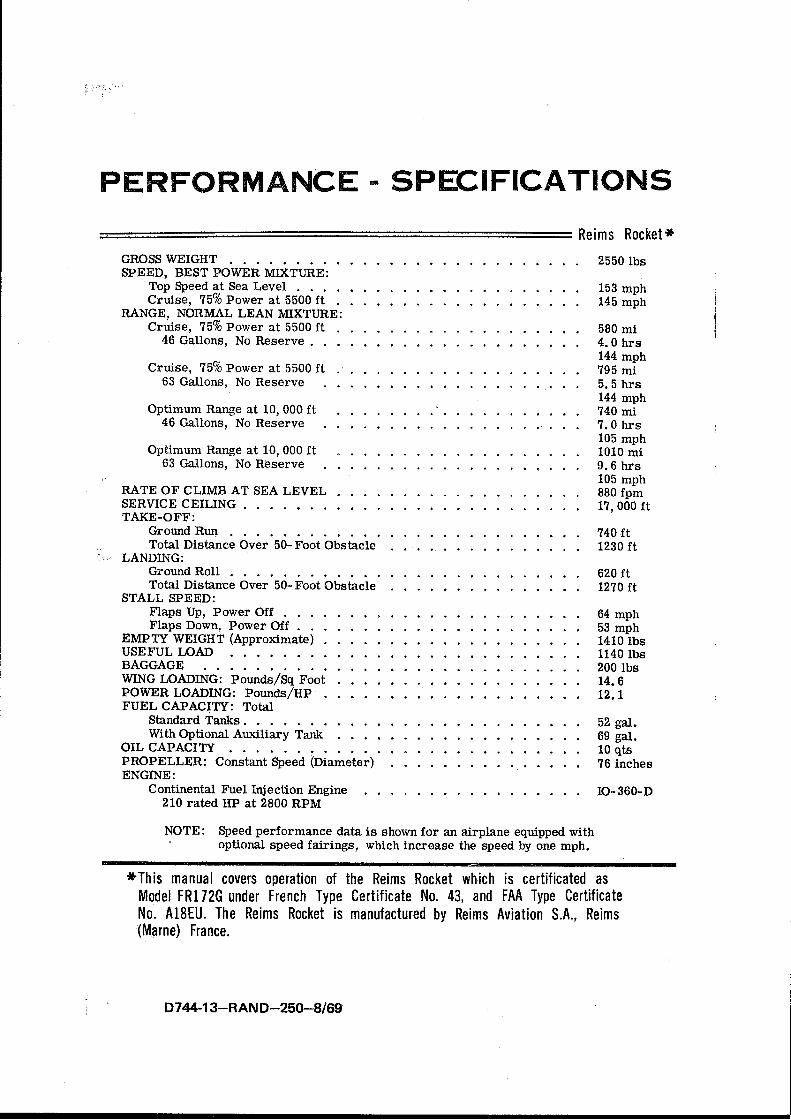
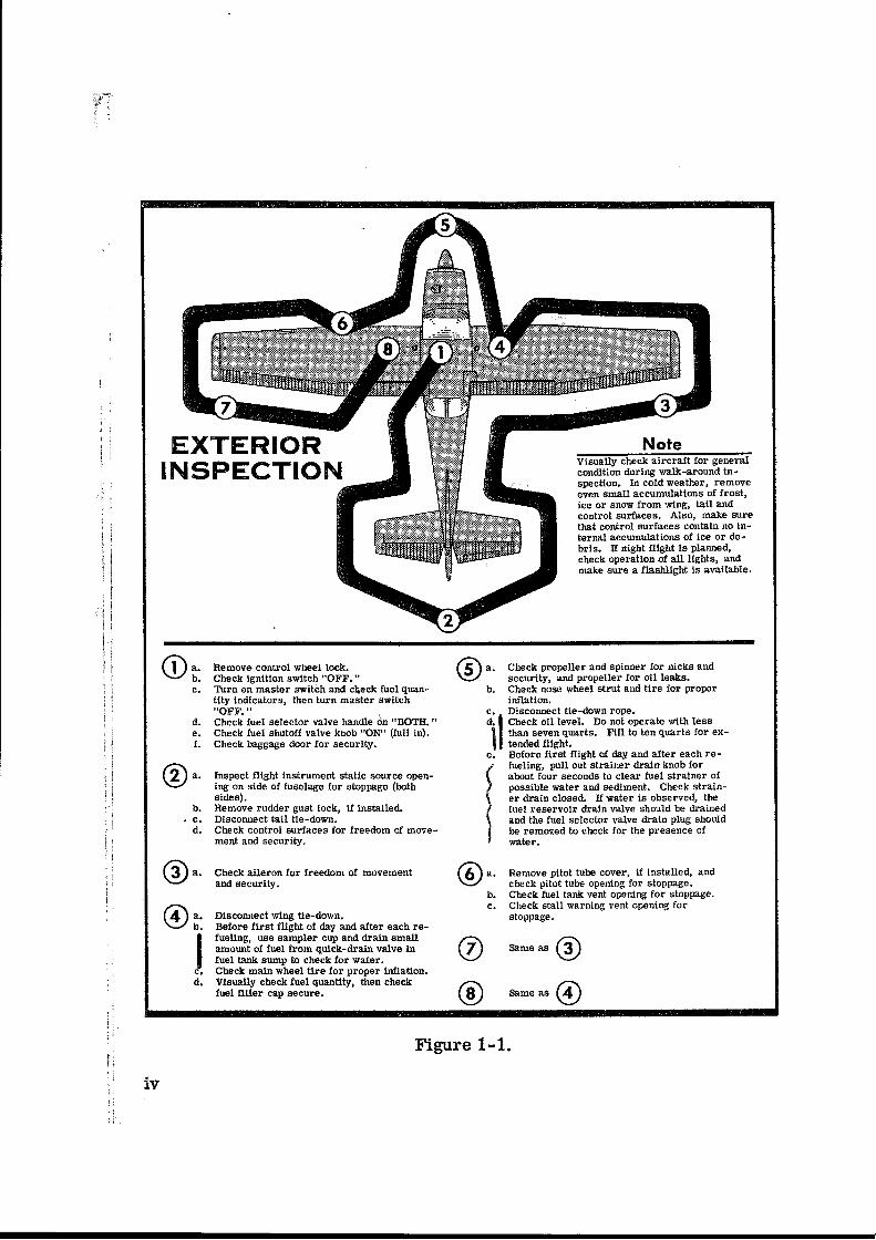
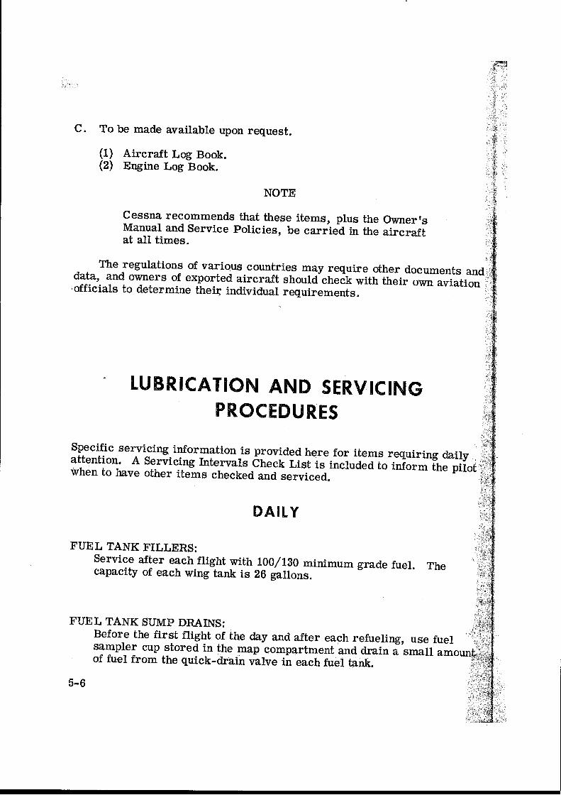
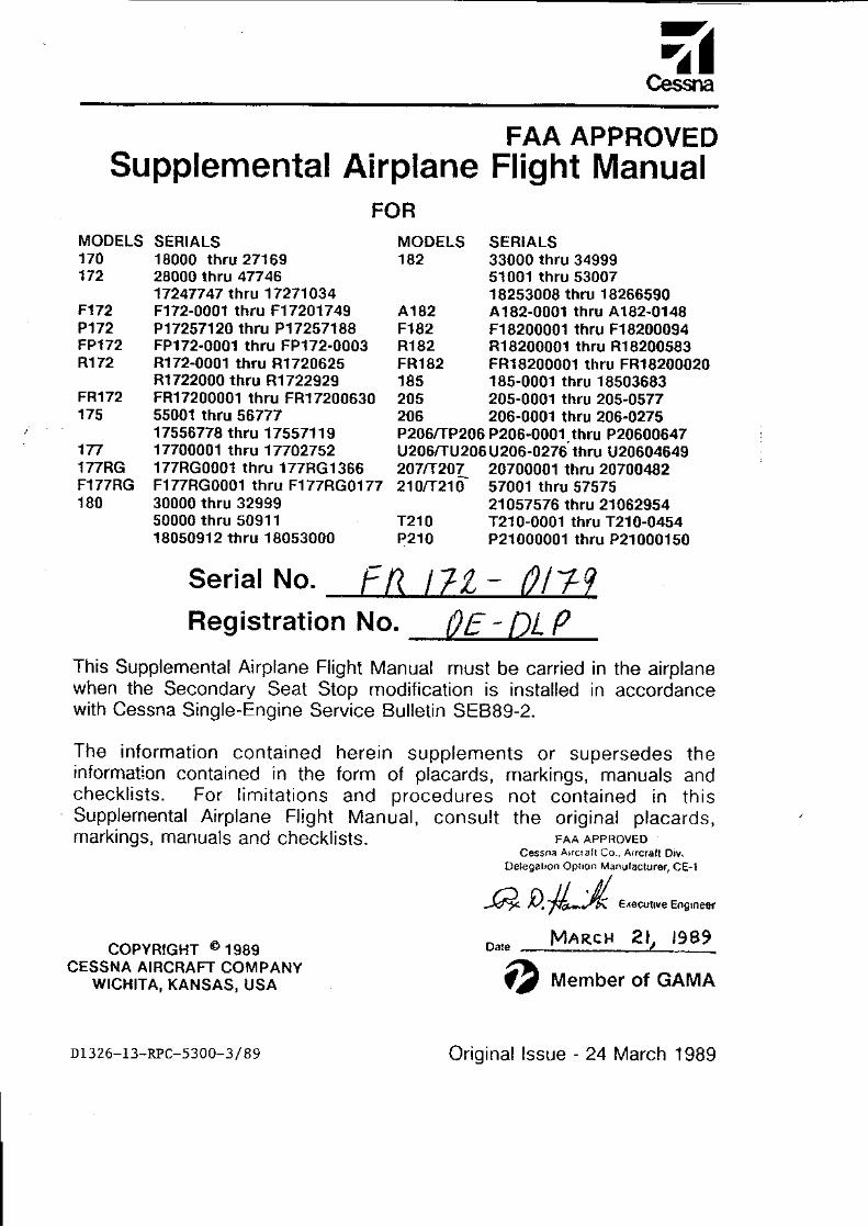
Flughandbuch C172
Cessna FR172G
OE-DLP
Dieses Exemplar ist eine aktuelle Kopie des Original-Flughandbuches, Stand 1.6.2005.
Inhalt: • Wägebericht • Working Tables für TKOF und LDG Performance,
Weight & Balance • Cessna „Owners Manual“ • Gültige “Supplements” • Ausrüstungsliste

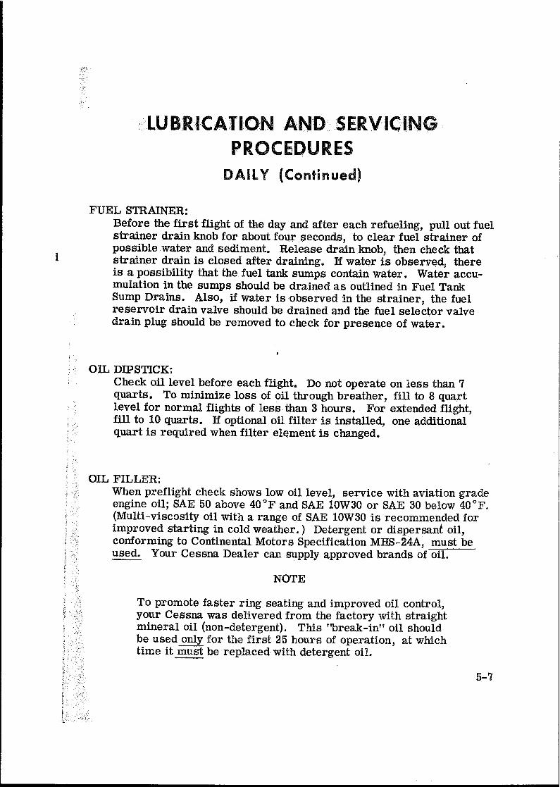
FHB_Deckbl_DLP_WorkingTables_20050601.doc
1.6.2005
C172Cessna FR172G
OE-DLP
Working Tables:
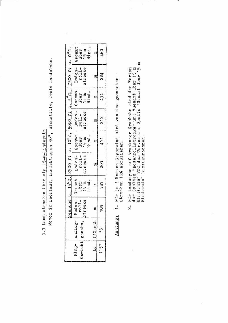
Take-off Performance (metric) Landing Performance (metric)
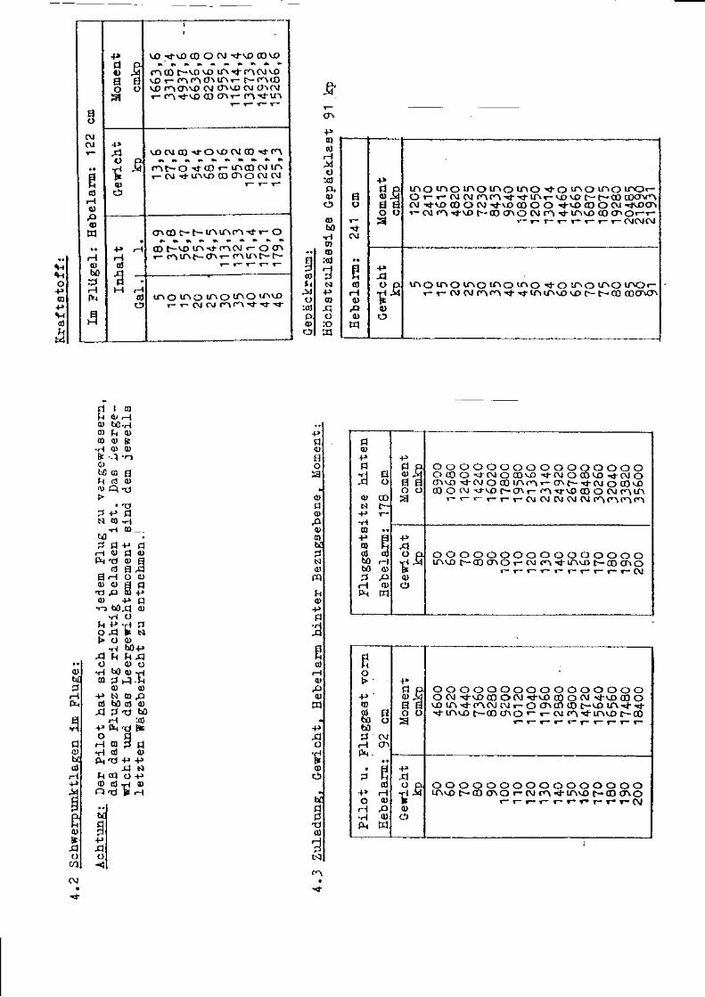
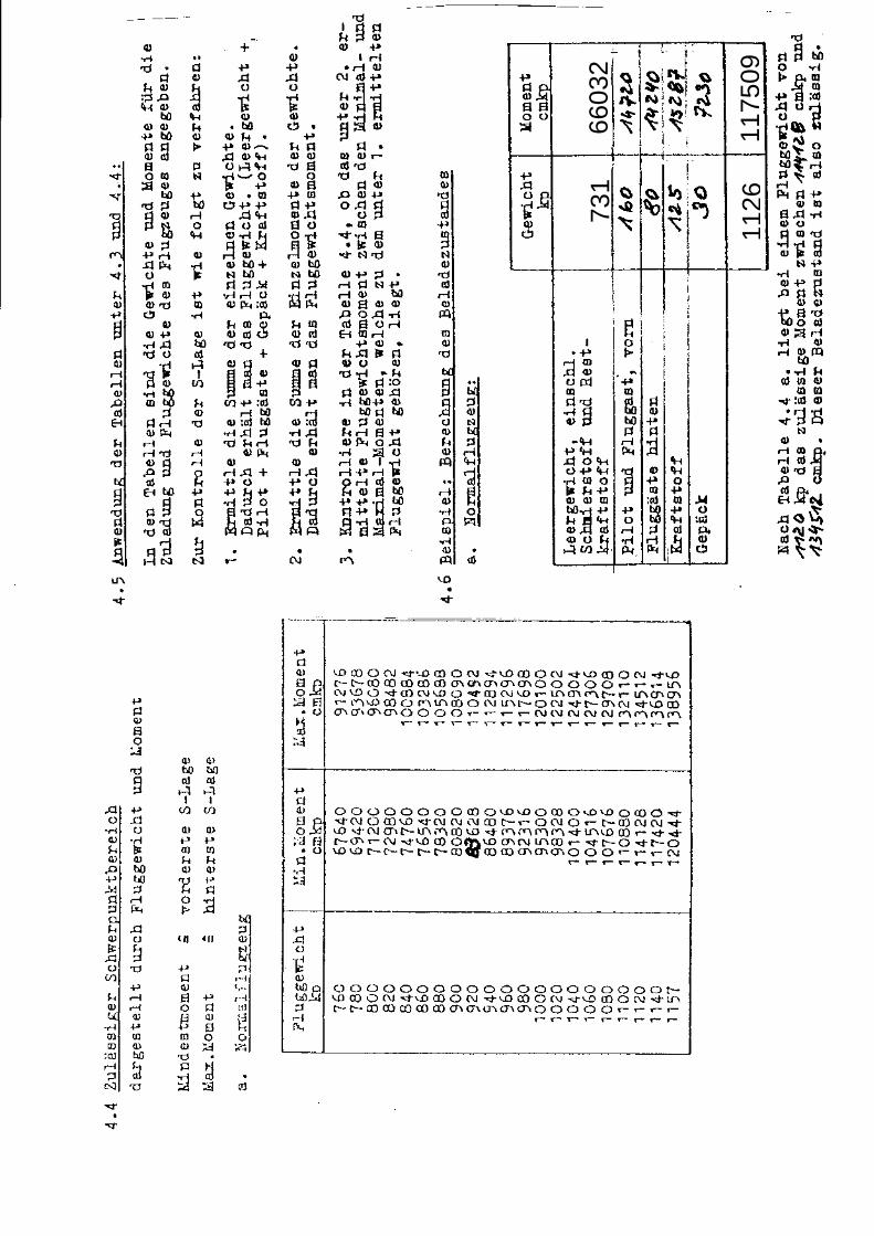
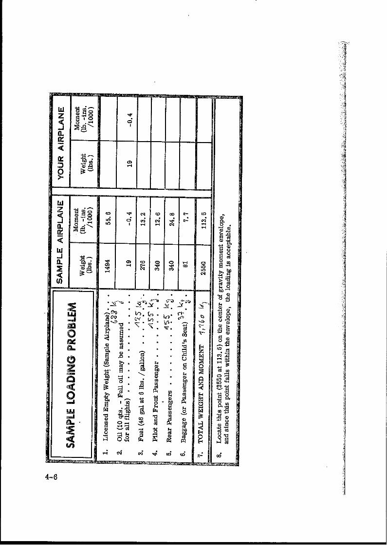
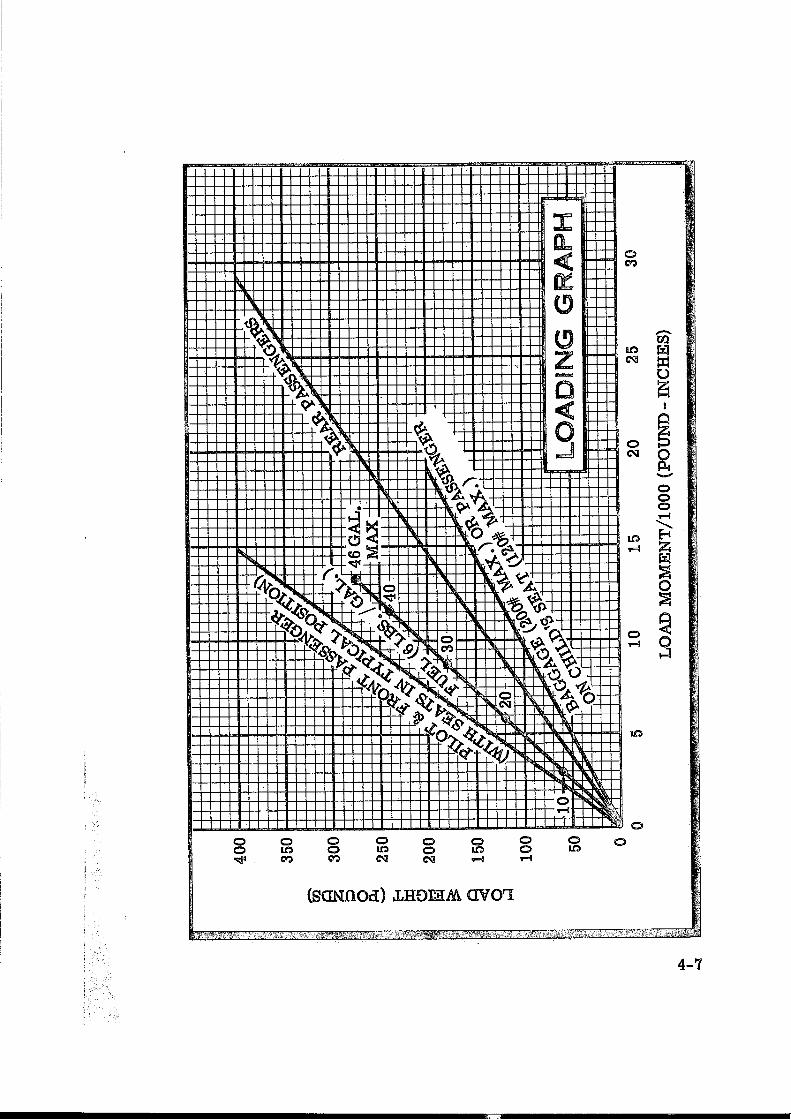
Weight and Balance
6603
273
1
1126
1175
09

INTENTIONALLY BLANK

INTENTIONALLY BLANK


INTENTIONALLY BLANK


FMS 017-FR172G-00 S0 Page: 2-1 Rev.1 14. February 2003
FMS 12-FR172G-00 S1 Page : 2-7 Rev. 0 25. June 1999
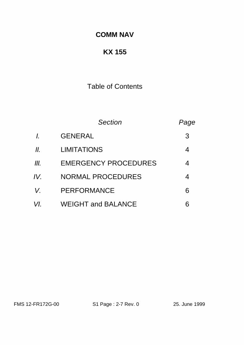
COMM NAV
KX 155
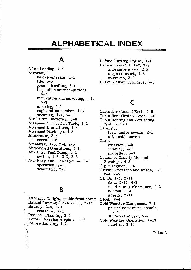
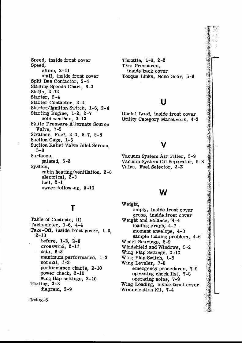
Table of Contents
Section
Page
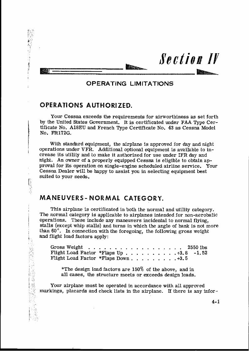
I.
GENERAL
3
II.
LIMITATIONS
4
III.
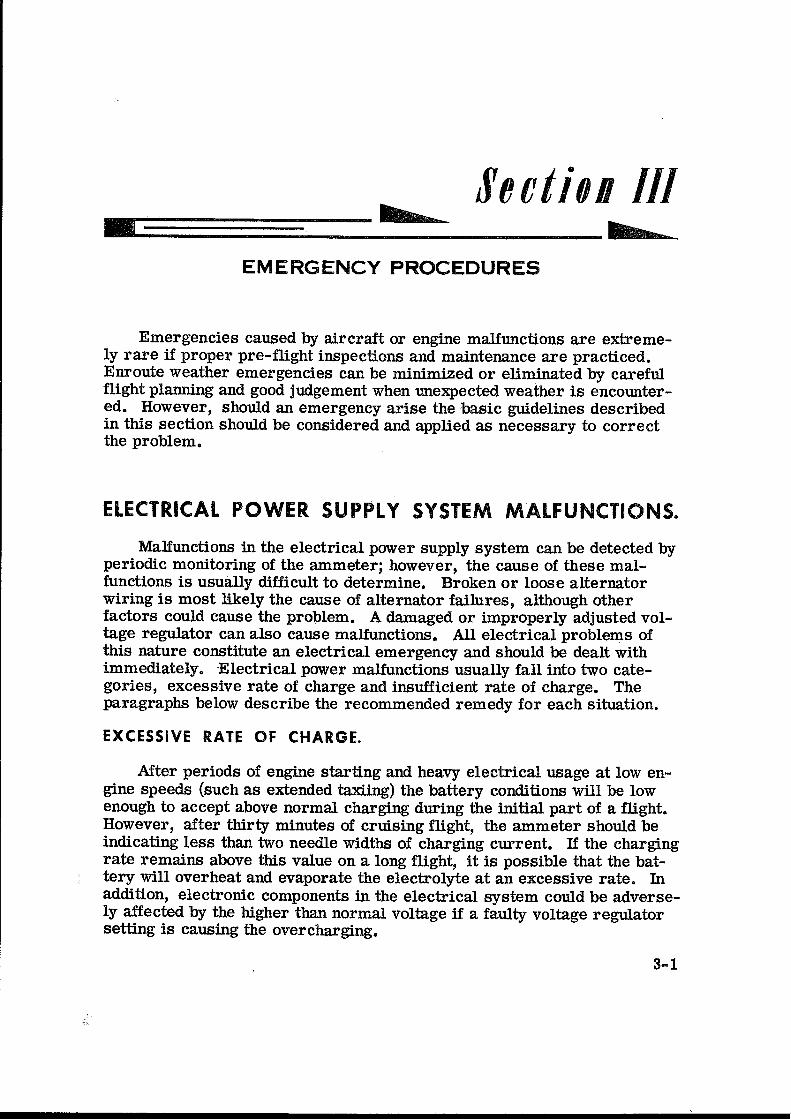
EMERGENCY PROCEDURES
4
IV.
NORMAL PROCEDURES
4
V.
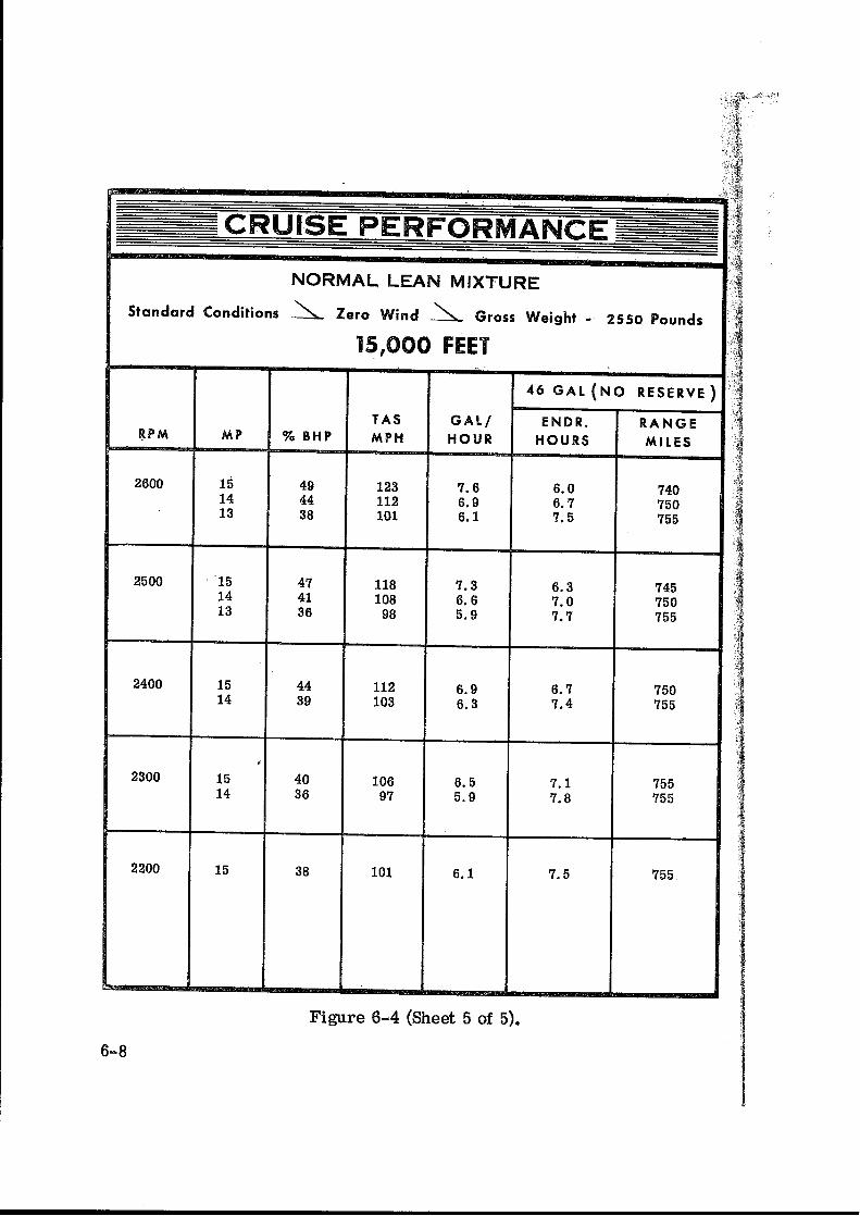
PERFORMANCE
6
VI.
WEIGHT and BALANCE
6
FMS 12-FR172G-00 S1 Page : 3-7 Rev. 0 25. June 1999
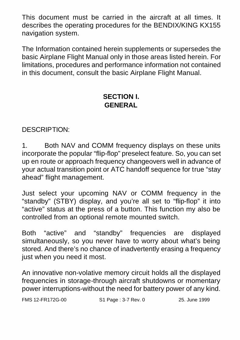
This document must be carried in the aircraft at all times. It describes the operating procedures for the BENDIX/KING KX155 navigation system. The Information contained herein supplements or supersedes the basic Airplane Flight Manual only in those areas listed herein. For limitations, procedures and performance information not contained in this document, consult the basic Airplane Flight Manual.
SECTION I. GENERAL
DESCRIPTION: 1. Both NAV and COMM frequency displays on these units incorporate the popular “flip-flop” preselect feature. So, you can set up en route or approach frequency changeovers well in advance of your actual transition point or ATC handoff sequence for true “stay ahead” flight management. Just select your upcoming NAV or COMM frequency in the “standby” (STBY) display, and you’re all set to “flip-flop” it into “active” status at the press of a button. This function my also be controlled from an optional remote mounted switch. Both “active” and “standby” frequencies are displayed simultaneously, so you never have to worry about what’s being stored. And there’s no chance of inadvertently erasing a frequency just when you need it most. An innovative non-volative memory circuit holds all the displayed frequencies in storage-through aircraft shutdowns or momentary power interruptions-without the need for battery power of any kind.
FMS 12-FR172G-00 S1 Page : 4-7 Rev. 0 25. June 1999
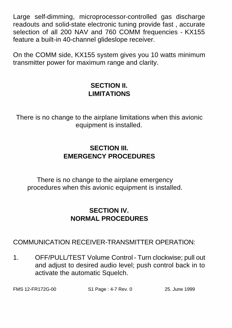
Large self-dimming, microprocessor-controlled gas discharge readouts and solid-state electronic tuning provide fast , accurate selection of all 200 NAV and 760 COMM frequencies - KX155 feature a built-in 40-channel glideslope receiver. On the COMM side, KX155 system gives you 10 watts minimum transmitter power for maximum range and clarity.
SECTION II. LIMITATIONS
There is no change to the airplane limitations when this avionic
equipment is installed.
SECTION III. EMERGENCY PROCEDURES
There is no change to the airplane emergency procedures when this avionic equipment is installed.
SECTION IV. NORMAL PROCEDURES
COMMUNICATION RECEIVER-TRANSMITTER OPERATION: 1. OFF/PULL/TEST Volume Control - Turn clockwise; pull out
and adjust to desired audio level; push control back in to activate the automatic Squelch.
FMS 12-FR172G-00 S1 Page : 5-7 Rev. 0 25. June 1999
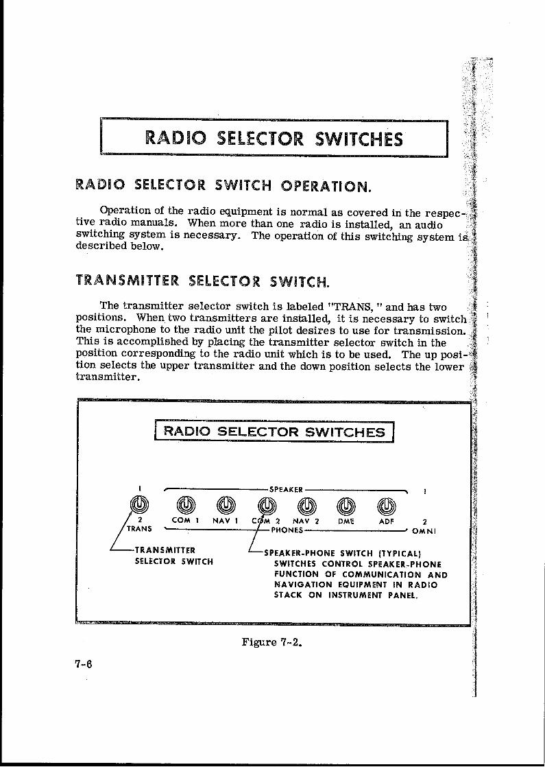
2. MIC Selector Switch (on audio control panel) - SET to COMM 1.
3. SPEAKER Selector (on audio control panel) - SET to desired mode.
4. COMM Frequency Selector Knobs - Select desired operating frequency.
5. COMM Transfer Button - PRESS to transfer desired frequency from the STBY display into the COMM display.
6. MIC Button: a. To transmit - Press button and speak in microphone.
NOTE
During COMM transmission, a lighted “T” will appear between
the “COMM” and “STBY” displays to indicate that the transceiver is operating in the transmit code.
b. To Receive - RELEASE mike button.
NAVIGATION RECEIVER OPERATION: 1. NAV Frequency Selector Knobs - SELECT desired
operating frequency in “STBY” display. 2. NAV TRANSFER BUTTON - PRESS to transfer desired
frequency from the “STBY” display into the “NAV” display. 3. Speaker Selector (on audio panel) - SET to desired
mode. 4. NAV Volume Control -
a. ADJUST to desired audio level. b. PULL out to identify station.
VOR OPERATION: Channel the NAV Receiver to the desired VOR and monitor the
FMS 12-FR172G-00 S1 Page : 6-7 Rev. 0 25. June 1999
audio to positively identify the station. To select an OBS course, turn the OBS knob to set the desired course. When a signal is received, the NAV flag will pull out of view and show a “TO” or “FROM” flag as appropriate for the selected course. LOC OPERATION: Localizer circuitry is energized when the NAV Receiver is channelled to an ILS frequency. Monitor the LOC audio and positively identify the station. The NAV flag will be out of view when the signal is of sufficient strength to be usable. GLIDE SLOPE OPERATION: The glide slope receiver is automatically channelled when a localizer frequency is selected. A separate warning flag is provided to indicate usable signal conditions.
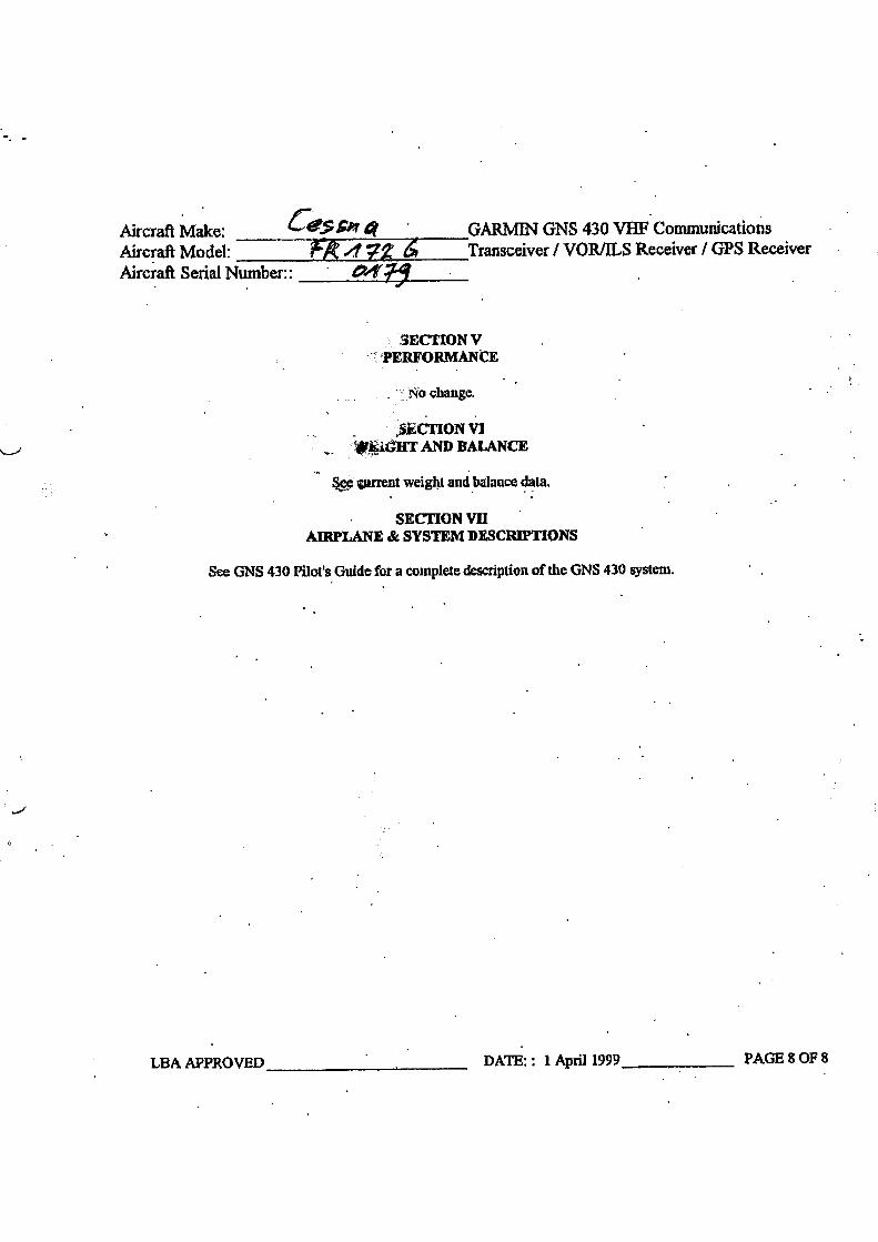
SECTION V. PERFORMANCE
There is no change to the airplane performance when this avionic equipment is installed.
SECTION VI. WEIGHT AND BALANCE
See current weight and balance data.

FMS 12-FR172G-00 S1 Page : 7-7 Rev. 0 25. June 1999
This page intentionally left blank.

INTENTIONALLY BLANK
FMS 017-FR172G-00 S2 Page: 2-15 Rev. 1 14. February 2003
ADF
KR 87
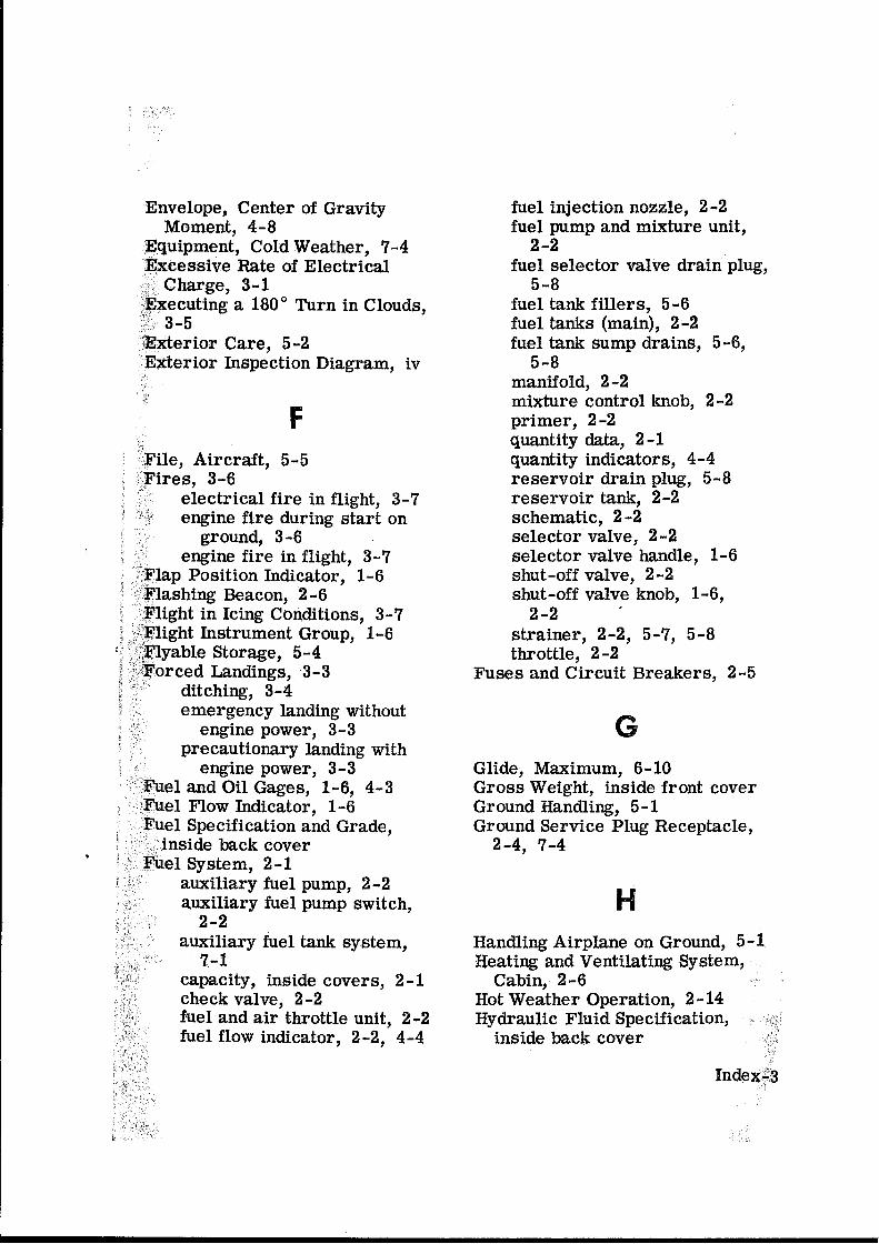
Table of Contents
Section
Page
I.
GENERAL
3
II.
LIMITATIONS
9
III.
EMERGENCY PROCEDURES
9
IV.
OPERATION
9
V.
PERFORMANCE
14
VI.
WEIGHT and BALANCE
14
FMS 017-FR172G-00 S2 Page: 3-15 Rev. 1 14. February 2003
This document must be carried in the aircraft at all times. It describes the operating procedures for the B/K ADF KR87 navigation system when it has been installed in accordance with B/K Installation Manual 006-05184-0007 Rev. 7 and ACG approved of EO 017-FR172G-00. For aircraft with an FAA Approved Airplane Flight Manual, this document serves as the ACG Approved Flight Manual Supplement for the B/K ADF KR87. For aircraft that do not have an Approved flight manual, this document serves as the ACG Approved Supplemental Flight Manual for the B/K ADF KR87. The Information contained herein supplements or supersedes the basic Airplane Flight Manual only in those areas listed herein. For limitations, procedures and performance information not contained in this document, consult the basic Airplane Flight Manual.
SECTION I. GENERAL
DESCRIPTION: The Bendix/King Digital ADF is a panel-mounted, digitally tuned automatic direction finder. It is designed to provide continuous 1-kHz digital tuning in the frequency range of 200-kHz to 1799-kHz and eliminates the need for mechanical band switching. The system is comprised of a receiver, a buil-in electronics timer, a bearing indicator, and a KA-44B combined loop and sense antenna. Operating controls and displays for the Bendix/King Digital ADF are shown and described in Figure 1.
FMS 017-FR172G-00 S2 Page: 4-15 Rev. 1 14. February 2003
The audio system used in conjunction with this radio for speaker-phone selection is shown and described in Supplement 1 of this handbook. The Bendix/King Digital ADF can be used for position plotting and homing procedures, and for aural reception of amplitude-modulated (AM) signals. The “flip-flop” frequency display allows switching between pre-selected “STANDBY” and “ACTIVE” frequencies by pressing the frequency transfer button. Both pre-selected frequencies are stored in a non-volatile memory circuit (no battery power required) and displayed in large, easy-to-read, self-dimming gas discharge numeric. The active frequency is continuously displayed in the left window, while the right window will display either the standby frequency or the selected readout from the built-in electronic timer. The built-in electronic timer has two separate and independent timing functions. An automatic flight timer that starts whenever the unit is turned on, functions up to 59 hours and 59 minutes. And an elapsed timer which will count up or down for up to 59 minutes and 59 seconds. When a preset time interval has been programmed and the countdown reaches :00, the display will flash for 15 seconds. Since both the flight timer and elapsed timer operate independently, it is possible to monitor either one without disrupting the other. The pushbutton controls and the bearing indicators are internally lighted. Intensity is controlled by the RADIO light dimming rheostat.
FMS 017-FR172G-00 S2 Page: 5-15 Rev. 1 14. February 2003
ANT/ADF MODE ANNUNCIATOR: Antenna (ANT) is selected by the “out” position of the ADF button. This mode improves the audio reception and is usually used for station identification. The bearing pointer is deactivated and will park in the 90° relative position. Automatic Direction Finder (ADF) mode is selected by the depressed position of the ADF button. This mode activates the bearing pointer. The bearing pointer will point in the direction of the station relative to the aircraft heading. IN-USE FREQUENCY DISPLAY: The frequency to which the ADF is tuned is displayed here. The active ADF frequency can be changed directly when either of the timer functions is selected.
FMS 017-FR172G-00 S2 Page: 6-15 Rev. 1 14. February 2003
BFO (Beat Frequency Oscillator) ANNUNCIATOR: The BFO mode, activated and annunciated when the “BFO” button is depressed, permits the carrier wave and associated morse code identifier broadcast on the carrier wave to be heard.
NOTE
CW signals (Morse Code) are unmodulated and no audio will be heard without use of BFO. This type of signal is not used in the United States air navigation. It is used in some foreign countries and marine beacons. STANDBY FREQUENCY/FLIGHT TIME OR ELAPSED TIME ANNUNCIATION: When FRQ is displayed the STANDBY frequency is displayed in the right hand display. The STANDBY frequency is selected using the frequency select knobs. The selected STANDBY frequency is put into the ACTIVE frequency windows by pressing the frequency transfer button. Either the standby frequency, the flight timer, or the elapsed time is displayed in this position. The flight timer and elapsed timer are displayed replacing the standby frequency which goes into “blind” memory to be called back at any time by depressing the FRQ button. Flight time or elapsed time are displayed and annunciated alternatively by depressing the FLT/ET button.
FMS 017-FR172G-00 S2 Page: 7-15 Rev. 1 14. February 2003
FLIGHT TIMER AND ELAPSED TIMER MODE ANNUNCIATION: Either the elapsed time (ET) or flight time (FLT) mode is annunciated here. FREQUENCY SELECT KNOBS: Selects the standby frequency when FRQ is displayed and directly selects the active frequency whenever either of the time functions is selected. The frequency selector knobs may be rotated either clockwise or counterclockwise. The small knob is pulled out to tune the 1's. The small knob is pushed in to tune the 10's . The outer knob tunes the 100's with rollover into the 1000's up to 1799. The knobs are also used to set the desired time when the elapsed timer is used in the countdown mode. ON/OFF/VOLUME CONTROL SWITCH (ON/OFF/VOL): Controls primary power and audio output level. Clockwise rotation from OFF position applies primary power to the receiver; further clockwise rotation increases audio level. Audio muting causes the audio output to be muted unless the receiver is locked on a valid station. SET/RESET ELAPSED TIMER BUTTON (SET/RST): The set/reset button when pressed resets the elapsed timer whether it is being displayed or not.
FMS 017-FR172G-00 S2 Page: 8-15 Rev. 1 14. February 2003
FLIGHT TIMER/ELAPSED TIMER MODE SELECTOR BUTTON (FLT/ET): The Flight Timer/Elapsed Timer mode selector button when pressed alternatively selects either Flight Timer mode or Elapsed Timer mode. FREQUENCY TRANSFER BUTTON (FRQ): The FRQ transfer button when pressed exchanges the active and standby frequencies. The new frequency becomes active and the former active frequency goes into standby. BFO (Beat Frequency Oscillator) BUTTON: The BFO button selects the BFO mode when in the depressed position. (See note under item 3.) ADF BUTTON: The ADF button selects either the ANT mode or the ADF mode. The ANT mode is selected with the ADF button in the out position. The ADF mode is selected with the ADF button in the depressed position. LUBBER LINE: Indicates relative or magnetic heading of the aircraft. The heading must be manually input by the pilot with the heading (HDG) knob.
FMS 017-FR172G-00 S2 Page: 9-15 Rev. 1 14. February 2003
COMPASS CARD: Manually rotatable card that indicates relative or magnetic heading of aircraft, as selected by HDG knob. BEARING POINTER: Indicates relative or magnetic bearing to station as selected by HDG knob. If the relative heading of North (N) is manually selected under the lubber line by the pilot, then the bearing pointer indicates the relative bearing to the station. If the aircraft’s magnetic heading is selected under the lubber line by the pilot, then the bearing pointer indicates the magnetic bearing to the station. HEADING KNOB (HDG): Rotates card to set in relative or magnetic heading of aircraft.
SECTION II. LIMITATIONS
There is no change to airplane limitations when the KR 87 ADF is installed.
FMS 017-FR172G-00 S2 Page: 10-15 Rev. 1 14. February 2003
SECTION III. EMERGENCY PROCEDURES
There are no changes to the basic airplane emergency procedures when the KR 87 ADF is installed.
SECTION IV. NORMAL PROCEDURES
TO OPERATE AS AN AUTOMATIC DIRECTION FINDER: 1. OFF/VOL Control - ON. 2. Frequency Selector Knobs - SELECT desired
frequency in the standby frequency display. 3. FRQ Button - Press to move the desired frequency
from the standby to the active position. 4. ADF Selector Switch (on audio control panel) -
SELECT as desired. 5. OFF/VOL Control - SET to desired volume level and
identify that desired station is being received. 6. ADF Button - SELECT ADF mode and note relative
bearing on indicator. ADF TEST (PRE-FLIGHT or IN-FLIGHT): 1. ADF Button - SELECT ANT mode and note pointer
moves to 90° position.
FMS 017-FR172G-00 S2 Page: 11-15 Rev. 1 14. February 2003
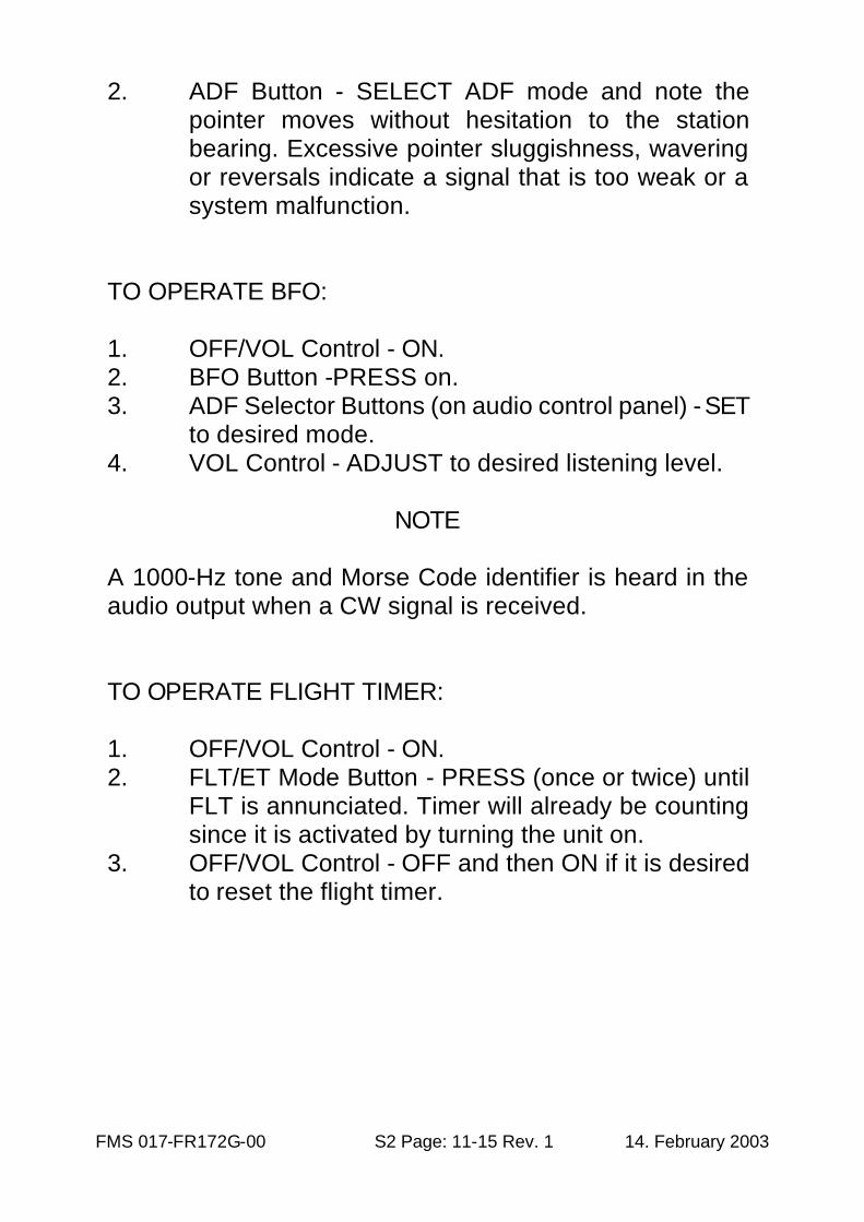
2. ADF Button - SELECT ADF mode and note the pointer moves without hesitation to the station bearing. Excessive pointer sluggishness, wavering or reversals indicate a signal that is too weak or a system malfunction.
TO OPERATE BFO: 1. OFF/VOL Control - ON. 2. BFO Button -PRESS on. 3. ADF Selector Buttons (on audio control panel) - SET
to desired mode. 4. VOL Control - ADJUST to desired listening level.
NOTE
A 1000-Hz tone and Morse Code identifier is heard in the audio output when a CW signal is received. TO OPERATE FLIGHT TIMER: 1. OFF/VOL Control - ON. 2. FLT/ET Mode Button - PRESS (once or twice) until
FLT is annunciated. Timer will already be counting since it is activated by turning the unit on.
3. OFF/VOL Control - OFF and then ON if it is desired to reset the flight timer.
FMS 017-FR172G-00 S2 Page: 12-15 Rev. 1 14. February 2003
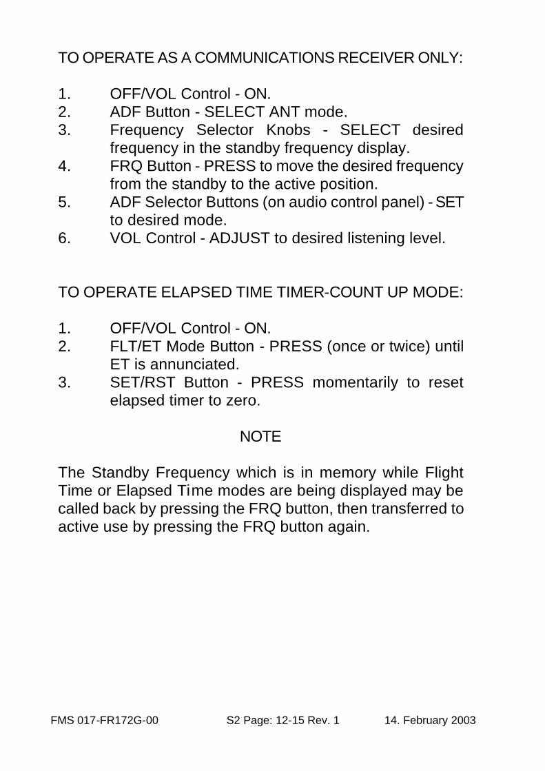
TO OPERATE AS A COMMUNICATIONS RECEIVER ONLY: 1. OFF/VOL Control - ON. 2. ADF Button - SELECT ANT mode. 3. Frequency Selector Knobs - SELECT desired
frequency in the standby frequency display. 4. FRQ Button - PRESS to move the desired frequency
from the standby to the active position. 5. ADF Selector Buttons (on audio control panel) - SET
to desired mode. 6. VOL Control - ADJUST to desired listening level. TO OPERATE ELAPSED TIME TIMER-COUNT UP MODE: 1. OFF/VOL Control - ON. 2. FLT/ET Mode Button - PRESS (once or twice) until
ET is annunciated. 3. SET/RST Button - PRESS momentarily to reset
elapsed timer to zero.
NOTE The Standby Frequency which is in memory while Flight Time or Elapsed Time modes are being displayed may be called back by pressing the FRQ button, then transferred to active use by pressing the FRQ button again.
FMS 017-FR172G-00 S2 Page: 13-15 Rev. 1 14. February 2003
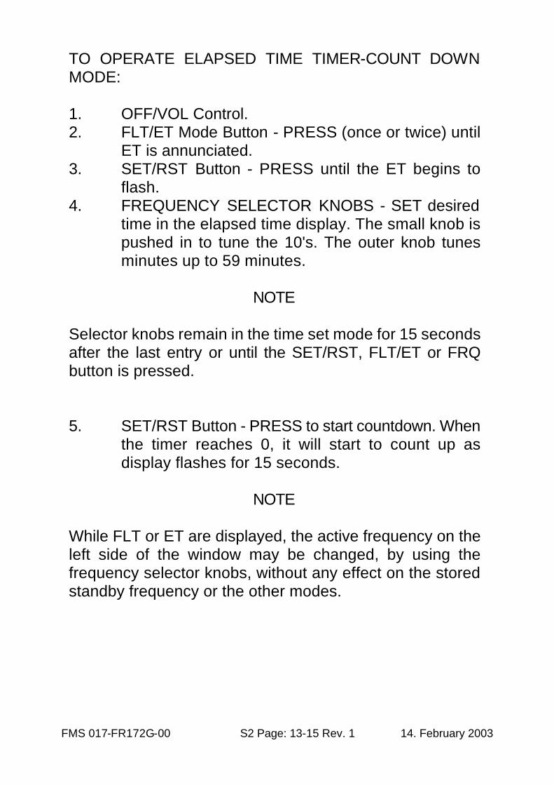
TO OPERATE ELAPSED TIME TIMER-COUNT DOWN MODE: 1. OFF/VOL Control. 2. FLT/ET Mode Button - PRESS (once or twice) until
ET is annunciated. 3. SET/RST Button - PRESS until the ET begins to
flash. 4. FREQUENCY SELECTOR KNOBS - SET desired
time in the elapsed time display. The small knob is pushed in to tune the 10's. The outer knob tunes minutes up to 59 minutes.
NOTE
Selector knobs remain in the time set mode for 15 seconds after the last entry or until the SET/RST, FLT/ET or FRQ button is pressed. 5. SET/RST Button - PRESS to start countdown. When
the timer reaches 0, it will start to count up as display flashes for 15 seconds.
NOTE
While FLT or ET are displayed, the active frequency on the left side of the window may be changed, by using the frequency selector knobs, without any effect on the stored standby frequency or the other modes.
FMS 017-FR172G-00 S2 Page: 14-15 Rev. 1 14. February 2003
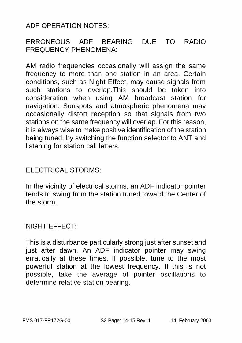
ADF OPERATION NOTES: ERRONEOUS ADF BEARING DUE TO RADIO FREQUENCY PHENOMENA: AM radio frequencies occasionally will assign the same frequency to more than one station in an area. Certain conditions, such as Night Effect, may cause signals from such stations to overlap.This should be taken into consideration when using AM broadcast station for navigation. Sunspots and atmospheric phenomena may occasionally distort reception so that signals from two stations on the same frequency will overlap. For this reason, it is always wise to make positive identification of the station being tuned, by switching the function selector to ANT and listening for station call letters. ELECTRICAL STORMS: In the vicinity of electrical storms, an ADF indicator pointer tends to swing from the station tuned toward the Center of the storm. NIGHT EFFECT: This is a disturbance particularly strong just after sunset and just after dawn. An ADF indicator pointer may swing erratically at these times. If possible, tune to the most powerful station at the lowest frequency. If this is not possible, take the average of pointer oscillations to determine relative station bearing.
FMS 017-FR172G-00 S2 Page: 15-15 Rev. 1 14. February 2003
MOUNTAIN EFFECT: Radio waves reflecting from the surface of mountains may cause the pointer to fluctuate or show an erroneous bearing. This should be taken into account when taking bearings over mountainous terrain. COASTAL REFRACTION: Radio waves may be refracted when passing from land to sea or when moving parallel to the coastline. This also should be taken into account.
SECTION V. PERFORMANCE
There is no change to the airplane performance when this avionic equipment is installed. However, the installation of an externally mounted antenna or related external antennas, will result in a minor reduction in cruise performance.
SECTION VI. WEIGHT AND BALANCE
See current weight and balance data.

INTENTIONALLY BLANK
PAGE 1 of 8
Cessna FR 172 G
Serial Nr. 0179
Flight Manual Supplement
Garmin GNS 430
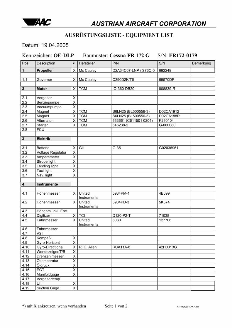
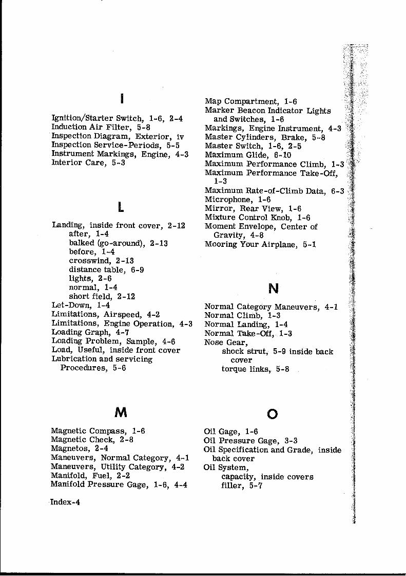
AUSTRIAN AIRCRAFT CORPORATION AUSRÜSTUNGSLISTE - EQUIPMENT LIST
Datum: 19.04.2005
Kennzeichen: OE-DLP Baumuster: Cessna FR 172 G S/N: FR172-0179 Pos. Description * Hersteller P/N S/N Bemerkung
1 Propeller X Mc Cauley D2A34C67-LNP / S76C-0 692249 1.1 Governor X Mc Cauley C290D2K/T6 69570DF 2 Motor X TCM IO-360-DB20 808839-R 2.1 Vergaser X 2.2 Benzinpumpe X 2.3 Vacuumpumpe X 2.4 Magnet X TCM S6LN25 (BL500556-3) D02CA1912 2.5 Magnet X TCM S6LN25 (BL500556-3) D02CA188R 2.6 Alternator X TCM 633661 (C611501 0204) K290104 2.7 Starter X TCM 646238-2 G-060080 2.8 FCU 3 Elektrik 3.1 Batterie X Gill G-35 G02036961 3.2 Voltage Regulator X 3.3 Amperemeter X 3.4 Strobe light X 3.5 Landing light X 3.6 Taxi light X 3.7 Nav. light X 4 Instrumente 4.1 Höhenmesser X United
Instruments 5934PM-1 4B099
4.2 Höhenmesser X United Instruments
5934PD-3 5K574
4.3 Höhenm. inkl. Enc. 4.4 Digitizer X TCI D120-P2-T 71038 4.5 Fahrtmesser X United
Instruments 8030 127706
4.6 Fahrtmesser 4.7 VSI 4.8 Kompaß X 4.9 Gyro-Horizont X 4.10 Gyro-Directional X R. C. Allen RCA11A-8 42H0313G 4.11 Wendezeiger/T/B X 4.12 Drehzahlmesser X 4.13 Öltemperatur X 4.14 Öldruck X 4.15 EGT X 4.16 Manifoldgage X 4.17 Vergasertemp. 4.18 Uhr X 4.19 Suction Gage X *) mit X ankreuzen, wenn vorhanden Seite 1 von 2 © copyright AAC Graz
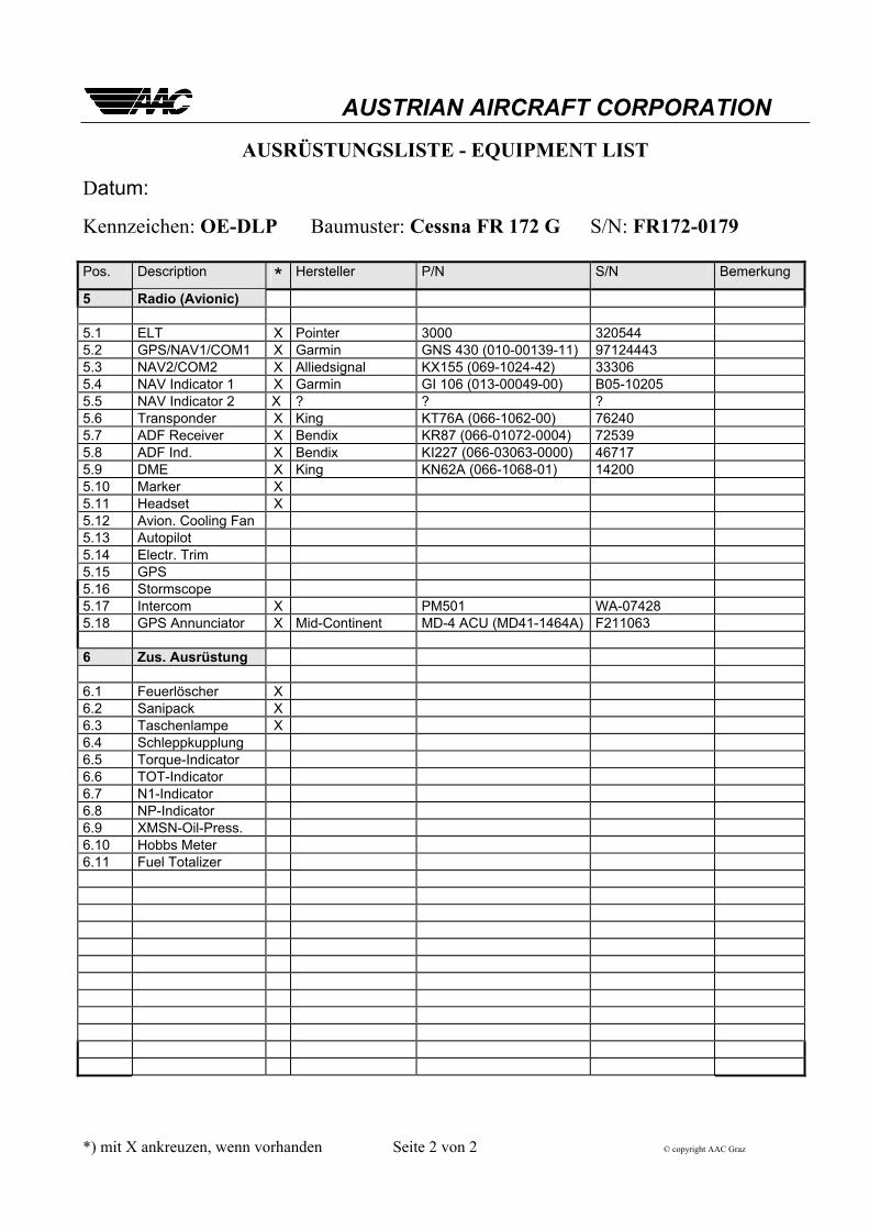
AUSTRIAN AIRCRAFT CORPORATION AUSRÜSTUNGSLISTE - EQUIPMENT LIST
Datum:
Kennzeichen: OE-DLP Baumuster: Cessna FR 172 G S/N: FR172-0179 Pos. Description * Hersteller P/N S/N Bemerkung
5 Radio (Avionic) 5.1 ELT X Pointer 3000 320544 5.2 GPS/NAV1/COM1 X Garmin GNS 430 (010-00139-11) 97124443 5.3 NAV2/COM2 X Alliedsignal KX155 (069-1024-42) 33306 5.4 NAV Indicator 1 X Garmin GI 106 (013-00049-00) B05-10205 5.5 NAV Indicator 2 X ? ? ? 5.6 Transponder X King KT76A (066-1062-00) 76240 5.7 ADF Receiver X Bendix KR87 (066-01072-0004) 72539 5.8 ADF Ind. X Bendix KI227 (066-03063-0000) 46717 5.9 DME X King KN62A (066-1068-01) 14200 5.10 Marker X 5.11 Headset X 5.12 Avion. Cooling Fan 5.13 Autopilot 5.14 Electr. Trim 5.15 GPS 5.16 Stormscope 5.17 Intercom X PM501 WA-07428 5.18 GPS Annunciator X Mid-Continent MD-4 ACU (MD41-1464A) F211063 6 Zus. Ausrüstung 6.1 Feuerlöscher X 6.2 Sanipack X 6.3 Taschenlampe X 6.4 Schleppkupplung 6.5 Torque-Indicator 6.6 TOT-Indicator 6.7 N1-Indicator 6.8 NP-Indicator 6.9 XMSN-Oil-Press. 6.10 Hobbs Meter 6.11 Fuel Totalizer *) mit X ankreuzen, wenn vorhanden Seite 2 von 2 © copyright AAC Graz


![090414 GA-Flugzeugmarkt der Zukunft - HFB MFGhfb-motorfluggruppe.airbus-sg-hamburg.de/documents/090414_GA-Flu… · für C172 und DA40 Weight [kg]/PS 0,0 0,2 0,4 0,6 0,8 1,0 1,2 Gemini](https://img.pdfslide.org/doc/110x75/5b1492727f8b9a487c8db156/090414-ga-flugzeugmarkt-der-zukunft-hfb-mfghfb-fuer-c172-und-da40-weight.jpg)