Embed Size (px)
Citation preview
BedienungsanleitungOperation Manual
AC~DC=DCC
◄►
MM
NEMRailCom
Schienen-StopfexpressPlasser & Theurer 09-3X
Tamping machinePlasser & Theurer Stopfexpress 09-3X
1. Wichtige Hinweise ...................................... 22. Transport und Verpackung ......................... 33. Einführung/Eigenschaften ........................... 54. Betrieb ........................................................ 55. Konfiguration des Decoders ....................... 126. Wartung ...................................................... 177. Vorbild ......................................................... 198. Fehlersuche und Abhilfe ................................ 219. Ersatzteile ................................................... 2110. Technische Daten ...................................... 23
1. Important information ................................. 22. Transport and packaging ............................ 33. Introduction/Characteristics ........................ 54. Operation .................................................... 55. Configuration of the decoder ...................... 126. Maintenance ............................................... 177. Prototype .................................................... 198. Trouble-shooting ......................................... 219. Spare parts ................................................. 2110. Technical data ............................................ 23
RAILmotionSchienen
RAILMotion
RAILmotion
2
DE EN1. Wichtige HinweiseBitte lesen Sie vor der ersten Anwendung des Produktes bzw. dessen Einbau diese Bedienungs-anleitung aufmerksam durch. Bewahren Sie diese auf, sie ist Teil des Produktes.
1.1 Sicherer Betrieb
Vorsicht:
Verletzungsgefahr! Aufgrund der detaillierten Abbildung des Origi-nals bzw. der vorgesehenen Verwendung kann das Produkt Spitzen, Kanten und abbruchge-fährdete Teile aufweisen. Das Produkt gehört aus diesem Grund nicht in die Hände von Kin-dern!Stromschlaggefahr! Verwendetes Versorgungsgerät (Transformator, Netzteil) regelmäßig auf Schäden an Kabeln, Stecker, Gehäuse usw. prüfen. Bei Schäden am Versorgungsgerät dieses keinesfalls benutzen! Achtung: Das Modell enthält eine elektro-nische bzw. mechanische Baugruppe. Es darf nur an den dafür vorgesehenen Stellen geöffnet werden. Vermeiden Sie Beschädigungen oder bringen Sie es nicht mit Feuchtigkeit in Verbin-dung. Die genannten Baugruppen sind für den einwandfreien Betrieb erforderlich. Bruchgefahr! Modell stets vorsichtig am Gehäuse anfassen, da die filigranen Teile des Modells sonst abbre-chen könnten. Achtung: Betreiben Sie den Stopfexpress nie-mals unbeaufsichtigt!
1.2 Das Produkt richtig verwendenDieses Produkt ist bestimmt:- Zum Betrieb auf Modelleisenbahnanlagen der
Baugröße H0.- Zum Betrieb mit einem zugelassenen Modell-
bahntransformator mit einer Ausgangsspan-nung von max. 21 V bzw. an einer Digitalzen-trale der Formate DCC und/oder Märklin Moto-rola (MM), z. B. dem Viessmann Commander Art.-Nr. 5300.
- Zum Betrieb in trockenen Räumen.Jeder darüber hinausgehende Gebrauch gilt als nicht bestimmungsgemäß. Für daraus resultieren-de Schäden haftet der Hersteller nicht.
1. Important informationPlease read this manual completely and attentive-ly before using the product for the first time. Keep this manual. It is part of the product.
1.1 Safety instructions
Caution:
Risk of injury! Due to the detailed reproduction of the origi-nal and the intended use, this product can have peaks, edges and breakable parts. Therefore this product is not intended for children!
Electrical hazard! Please check the supply unit (transformer, power supply unit) regularly for damaged cables, plugs etc. or damage to the housing. Should there be any damage do not use this power supply anymore!Attention: The model contains an electronic respectively mechanical component. It may only be opened at the pre-assembled places. It may not be damaged or exposed to humidity. The component mentioned above is essential for proper operation.Risk of breakage! Please touch the case carefully to avoid break of filigree parts.Attention: Never leave the track maintenance train (tamping machine) unattended during op-eration!
1.2 Using the product for its correct purpose
This product is intended: - For operation on a model train layout H0 scale.- For operation with an approved transformer for
model trains with an output voltage of max 21 V respectively a digital command station supply-ing DCC and/or Märklin Motorola (MM) such as the Viessmann Commander item-No. 5300.
- For operation in dry rooms only.Using the product for any other purpose is not ap-proved and is considered incorrect. The manufac-turer is not responsible for any damage resulting from the improper use of this product.
3
Fig. 1Abb. 1
Arbeitsrichtungdirection of working
Aggregatrahmenaggregate frame
Schlitten mit Stopfeinheitsliding carriage with tamping unit
Antriebsdrehgestellbogie with drive unit
Dachteil abnehmbarremovable roof section
vornfront
hintenrear
1.3 Lieferumfang Kontrollieren Sie den Lieferumfang auf Vollständigkeit: - Modell Stopfexpress- Beutel mit Zurüst- und Ersatzteilen- Anleitung
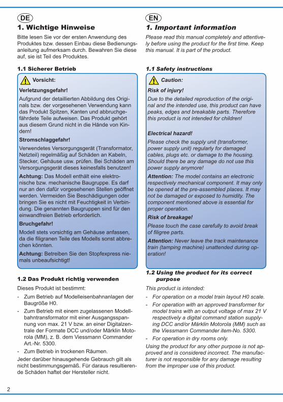
2. Transport und VerpackungDer Stopfexpress ist ein fein detailliertes und empfindliches Modell. Damit Sie lange Freude an diesem Zug haben, ist er gut verpackt und verschiedene Zurüstteile sind im Auslieferungs zustand nicht montiert. Wir empfehlen, den Stopfexpress bei Nichtgebrauch in der Original-verpackung zu lagern.
2.1 Fahrzeug aus der Originalverpackung entnehmen
Vorsicht:
Bruchgefahr! Modell stets vorsichtig mit beiden Händen am Gehäuse anfassen, da die filigranen Teile des Modells sonst abbrechen könnten. Niemals an Aggregatrahmen, Dach oder Drehgestellen festhalten, siehe Abb. 1.
Bitte alle Verpackungsteile und diese Anleitung für späteren Gebrauch aufbewahren. Nur die Ori-ginalverpackung garantiert Schutz vor Transport-schäden. Zur besseren Entnahme des Zuges aus dem Styroporträger ist dieser auf zwei Folienstrei-fen gebettet.
1.3 Checking the package contents
Check the contents of the package for completeness:- Model of the tamping machine- Pouch with detail parts and spare parts - Manual
2. Transport and packagingThe tamping machine is a finely detailed and sen-sitive model. To make sure that you can enjoy this train for a long time it is well packaged with many detail parts to be mounted by yourself. We recom-mend storing the tamping machine in the original packing when not in use.
2.1 Remove the vehicle from the original packing
Caution:
Risk of breakage! Always hold the model with both hands on the case, due some of the fine detail parts may break. Never hold it by the aggregate frame, the roof or the bogies, see fig. 1.
Please keep all parts of the packaging and this manual for later use. Only the original packaging protects the model from transport damage. The train is placed on two foils for easier removal from the styrofoam base.
StopfexpressTamping machine
4
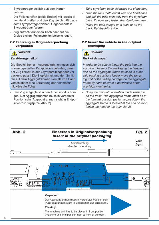
Fig. 2Abb. 2
Arbeitsrichtungdirection of working
vornfront
Verpacken: Der Aggregatrahmen muss in vorderster Position sein (Aggregatrahmen steht in Endposition zur Zugspitze).Packing: The machine unit has to be placed in front position (machine unit final position next to front of the train).
- Styroporträger seitlich aus dem Karton nehmen.
- Die Folienstreifen (beide Enden) mit jeweils ei-ner Hand greifen und den Zug gleichmäßig aus dem Styroporträger ziehen. Gegebenenfalls Styroporträger fixieren.
- Zug aufrecht auf einen Tisch oder auf die Gleise stellen. Folienstreifen beiseite legen.
2.2 Fahrzeug in Originalverpackung verpacken
Vorsicht:
Zerstörungsrisiko!
Die Stopfeinheit am Aggregatrahmen muss sich in einer speziellen Parkposition befinden, damit der Zug korrekt in den Styroporeinleger der Ver-packung passt! Die Stopfeinheit und den Schlit-ten auf dem Aggregatrahmen niemals von Hand verschieben! Eine Zerstörung der Feinmecha-nik wäre die Folge.
- Den Zug aufgegleist in den Arbeitsmodus brin-gen. Der Aggregatrahmen muss in vorderster Position sein (Aggregatrahmen steht in Endpo-sition zur Zugspitze, Abb. 2).
- Take styrofoam base sideways out of the box. - Grab the foils (both ends) with one hand each
and pull the train uniformly from the styrofoam base. If necessary fasten the styrofoam base.
- Place the train upright on a table or on the track. Put the foils aside.
2.2 Insert the vehicle in the original packaging
Caution:
Risk of damage!
In order to be able to insert the train into the styrofoam base of the packaging the tamping unit on the aggregate frame must be in a spe-cific parking position! Never move the tamp-ing unit or the sliding carriage on the aggregate frame by hand to avoid a destruction of the precision mechanics.
- Bring the train into operation mode while it is on the track. The aggregate frame must be in the forward position (as far as possible – the aggregate frame is located at the end position facing the head of the train, fig. 2).
Einsetzen in OriginalverpackungInsert in the original packaging
5
- Zur Aktivierung des Arbeitsmodus beachten Sie bitte die entsprechenden Kapitel weiter unten! Nach Positionierung des Aggregatrahmens in vorderster Stellung Zug stromlos schalten und vom Gleis nehmen.
- Folienstreifen im Abstand der Hauptdrehge-stelle parallel auf einen weichen Untergrund le-gen (z. B. Schaumstoffunterlage).
- Zug so seitlich auf die Folienstreifen legen, dass die vordere Kabine (Zugspitze) links ist.
- Die Folienstreifen (beide Enden) mit jeweils ei-ner Hand greifen und den Zug gleichmäßig mit der vorderen Kabine nach links in den Styro-porträger legen.
2.3 Fahrzeug anheben/tragen Fassen Sie den Stopfexpress stets am Gehäuse an. Benutzen Sie stets beide Hände zum Anhe-ben und Tragen des Zuges. Niemals an Aggregat-rahmen, Dach oder Drehgestellen festhalten.
3. Einführung/Eigenschaften Der Stopfexpress 09-3X von Plasser & Theurer stellt eine ebenso eindrucksvolle wie hochtechni-sierte Arbeitsmaschine für den Gleisbau dar. Er dient der optimalen und dauerhaften Stopfung des Schotterbettes. Im H0-Maßstab ist die Gleisbaumaschine mit Sound, Lichteffekten und Bewegungsfunktionen eine faszinierende Erscheinung. Im Fahrmodus fährt der Zug wie eine gewöhn-liche Lok dank seines leistungsstarken Kompakt-antriebs seidenweich vorwärts bzw. rückwärts. Bei Arbeitsfahrt fährt der Zug mit Arbeitsgeschwindig-keit und laufender Stopfeinheit in Arbeitsrichtung. Attraktive Funktionen sowie Sound sind auch im Analogbetrieb verfügbar, allerdings dann system-bedingt nicht individuell schaltbar.
4. BetriebDer Stopfexpress ist für analogen und digitalen Betrieb geeignet. Für den vorbildgerechten Ein-satz und die Nutzung aller Zusatzfunktionen emp-fehlen wir die Verwendung eines Digitalsystems. Der integrierte Decoder versteht die Digitalformate Märklin-Motorola (MM) und DCC. Automatische Erkennung des angesprochenen Digitalformates. Werkseinstellung: 03 (DCC/MM). Fahrstufenmodus: DCC 28 Fahrstufen
- For activating the operation mode please refer to the chapter further on in this manual! Once the aggregate frame is located in the forward position turn off the power and remove the train from the track.
- Place the foils at the same distance as the main bogies parallel on a soft base (e. g.: foam support).
- Place the train on the foils sideways in such a way that the forward cabin (head of train) is on the left.
- Grab the foils (both ends) with one hand each and insert the train uniformly into the styrofoam base with the forward cabin being on the left.
2.3 Lifting and carrying the vehicle
Always hold the tamping machine at the hous-ing and use both hands for lifting and carrying the train. Never hold it by touching the aggregate frame, the roof or the bogies.
3. Introduction/Characteristics The tamping machine 09-3X by Plasser & Theur-er represents an impressive and highly technical working plant for track construction. It serves for optimal and durable tamping of the ballast. With its sound, lighting effects and motion func-tions this model is truly fascinating.Due to its powerful and compact drive mechanism this train runs like any other locomotive forwards and backwards when in driving mode. In operation mode the train moves at a very slow working speed and moving tamping mechanism in working direction. Attractive functions as well as sound are also available in analogue mode. How-ever, due to the system characteristics the func-tions cannot be switched individually in analogue mode.
4. OperationThe tamping machine is suitable for both ana-logue and digital operation. We recommend oper-ating this model in digital mode in order to fully uti-lise all available functions. The integrated decoder works with both the Märklin Motorola (MM) and DCC digital formats. It automatically recognizes the digital format. Factory setting: 03 (DCC/MM). Speed step mode: DCC 28 speed steps
6
Tipp: Bei Verwendung einer multiprotokollfähigen Di-gitalzentrale empfehlen wir den Betrieb mit dem Protokoll DCC und einer digitalen Ausgangsspan-nung von 17 – 21 V. So lassen sich die optimalen Betriebseigenschaften erzielen. Beachten Sie: Für Stopfbetrieb im Analogbetrieb sind mindestens 14 Volt am Gleis erforderlich.
4.1 Funktionsumfang Sämtliche digital schaltbaren Funktionen des Stopfexpress entnehmen Sie bitte der Tabelle un-ten. Der Stopfexpress verfügt über folgende Aus-stattung: - Fahren im Fahrmodus vorwärts/rückwärts
(digital, analog). - Arbeitsmodus mit funktionsfähiger Stopfeinheit
(digital, analog). - RailCom-fähiger Digitaldecoder für DCC/MM
und Analogbetrieb. - Funktionen der Stopfeinheit digital schaltbar. - Lichtfunktionen: fahrtrichtungsabhängige Drei-
licht-Spitzenbeleuchtung / rote Schlussleuch-ten, gelbe Warnblinkleuchten sowie weiße Arbeitsraumbeleuchtung.
- Soundmodul für verschiedene Betriebsge-räusche.
- Fahrwerksgeführt mitschwenkende Kupplungs-schächte nach NEM 362 beidseitig. Im Lieferzustand sind die Kupplungen nicht montiert.
- Lastregelung für Fahrbetrieb (digital). - Vorbildkonforme Höchstgeschwindigkeit auch
im Analogbetrieb durch automatische Anpas-sung an eine zu hohe Trafospannung.
- Unterstützung der RailCom-Datagramme Befehlsquittungen, CV-Inhalte, Adressbroad-cast.
4.2 FunktionstastenbelegungDie Zusatzfunktionen sind den Funktionstasten gemäß Tabelle auf Seite 7 zugeordnet:
Tipp: Bei den Funktionstasten (z. B. Pfeife und diverse Tasten zum manuellen Betätigen der Stopfeinheit) sollten, sofern die Zentrale dies unterstützt, die Momenttasten benutzt werden. Programmierung der Funktionen: Die Funktionen des Decoders richten Sie über die CV- oder Registerprogrammierung ein. Sämtliche Einstellmöglichkeiten finden Sie in Kapitel 5.
Hint: When using a multiprotocol digital command sta-tion we recommend operating this model with DCC at a digital output voltage ranging between 17 – 21 V. Thus you will achieve the optimal oper-ating properties.Please note: For the tamping operation in analogue mode the track voltage must be at least 14 Volt.
4.1 Scope of functions
All digitally controlled functions of the tamping ma-chine are shown in the table below. The tamping machine is equipped with the following functions: - Running in the running mode forward/reverse
(digital, analogue). - Working mode with functional tamping unit
(digital, analogue). - RailCom capable digital decoder for DCC/MM
and analogue operation. - Functions of tamping unit can be separately
switched in digital mode. - Lighting functions: Directional headlights (three
white headlights) / red tail lights, yellow warning beacons as well as white lighting of the working room.
- Sound module for various operating sounds. - Pivoting coupler pockets as per NEM 362 at
both ends. - Couplers are not mounted ex works. - Load control for running mode (digital). - Prototypical maximum speed even in analogue
mode due to automatic adaptation to excessive supply voltage.
- Supporting RailCom datagram command con-firmations, CV contents, address broadcast.
4.2 Allocation of function buttons
The auxiliary functions are mapped to the follow-ing function buttons:Hint: For certain functions (e. g. horn and others for controlling various features of the tamping unit) you should set the corresponding function buttons to momentary action (provided the command station supports this feature).Programming functions: You can set all functions of the decoder with the CV programming or in register mode. All available options are shown in chapter 5.
7
4.3 Aufgleisen
Vorsicht:
Bruchgefahr! Modell stets vorsichtig mit beiden Händen am Gehäuse anfassen, da die filigranen Teile des Modells sonst abbrechen könnten.
- Zug vorsichtig beidhändig über das Gleis heben.
- Den Zug leicht schräg nach hinten gekippt hal-ten und alle Räder einer Seite auf die hintere Schiene stellen. Anschließend den Zug wieder nach vorn neigen und darauf achten, dass alle Räder auf den Schienen stehen.
- Vergewissern Sie sich, dass alle Achsen kor-rekt auf dem Gleis stehen. Achten Sie beson-ders auf die kleinen Räder der Stopfeinheit.
4.4 Fahrmodus Im Fahrmodus fährt der Stopfexpress wie eine gewöhnliche Lokomotive. Geschwindigkeit und Fahrtrichtung sind abhängig von der Einstellung des Trafos bzw. der Digitalzentrale.
Taste Button
FunktionFunction
Analog Analogue
Erläuterungen Explanations
F0 Spitzenlicht/Schlusslicht / Front-/rear lights
ein on
Spitzen- und Schlusslicht sind nur gemeinsam schaltbar.
Front and rear lights can only be switched together.
F1 Soundmodul an/aus Sound module on/off
ein on
Im Stillstand sind bei Betätigen der Taste Start- bzw. Stopgeräusche des Antriebsmotors zu hören. Analogbetrieb: Soundmodul ist immer aktiv, außer das Lautstärke-Potenzi-ometer steht auf null oder Spannung am Gleis ist zu niedrig.
If the tamping machine stops by press-ing the push button the sounds of the engine are played. In analogue mode the sound is always active, except when the pot is set to zero, or there is not enough voltage on the track.
F2 Pfeife / Horn
- Pfeife ist nur aktivierbar, wenn F1 (Soundmodul) aktiv ist.
Horn can only be activated when F1 (sound module) is active.
F3 Warnblinkleuchten vorn/hinten /Dach Warning beacons front/back/roof
aus/auto off/auto
Wenn aktiv, spielen F6 und F7 keine Rolle. Im Arbeitsmodus immer aktiv.
If active, F6 and F7 are irrelevant. In operation mode always active.
F4 Arbeitsmodus / Working mode
aus Stopfbetrieb nur in Vorwärtsfahrt. Tamping mode only when train is running forward.
F5 Schlittenbeleuchtung / Sliding carriage lighting
aus/auto off/auto
Im Arbeitsmodus immer aktiv. In operation mode always active.
F6 Warnblinkleuchten vorn/hinten Warning beacons front/back
aus/auto off/auto
Im Arbeitsmodus immer aktiv. In operation mode always active.
F7 Warnblinkleuchten Dach / Warning beacons roof
aus/auto off/auto
Im Arbeitsmodus immer aktiv. In operation mode always active.
F8 1x Stopfen / 1x Tamping
- Nur im Arbeitsmodus (F4 = aktiv) und bei Geschwindigkeit 0 erlaubt. Entsprechende Geräusche werden wiedergegeben, wenn Sound aktiv.
Only in operation mode (F4 = active) and speed 0 is allowed. If the sound is turned on, the specific noises will also be played
F9 Schlitten nach vorn bewegen / Move sliding carriage forward
- Nur im Arbeitsmodus (F4 = aktiv) und bei Geschwindigkeit 0 erlaubt.
Only active in operation mode (F4 = active) and when speed is 0.
F10 Schlitten nach hinten bewegen / Move sliding carriage backwards
- Nur im Arbeitsmodus (F4 = aktiv) und bei Geschwindigkeit 0 erlaubt.
Only active in operation mode (F4 = active) and when speed is 0.
F11 - - - -F12 Rangiermodus /
Shunting mode- Rangiermodus halbiert alle Geschwin-
digkeiten und Beschleunigungsraten. Speed and acceleration are halved.
4.3 Placing the model on the track
Caution:
Risk of breakage! Always hold the model with both hands and place it carefully on the tracks, otherwise some detail parts may break off.
- Place train carefully with both hands onto the tracks.
- Hold the train slightly tilted backwards and make sure that all wheels of one side are firmly located on the track facing away from you; then tilt the train forward towards you and make sure all wheels are on the tracks.
- Double check that all wheels are on the tracks. Pay special attention to the small wheels of the tamping unit.
4.4 Running mode
In running mode the tamping machine operates like any other locomotive. Direction and speed are subject to the settings of the transformer or the throttle of the digital control station.
8
Hinweis: Beim Start des Stopfexpresses bzw. beim Verlas-sen des Arbeitsmodus fährt die Schlitteneinheit in ihre Fahrmodus-Position. Dieser Vorgang dauert ca. 2 Sekunden. Während dieser Zeit ist der Fahr-motor gesperrt. Der Stopfexpress setzt sich erst danach in Bewegung.
4.5 Digitalbetrieb (DCC/MM)Im Digitalbetrieb sind alle Funktionen verfügbar und über Funktionstasten separat steuerbar (vgl. Abschnitt 4.2 Funktionstastenbelegung). Im DCC-Betrieb beherrscht der Decoder die Fahrstufen-modi 14, 28 und 128 Fahrstufen. Die Lastregelung sorgt für seidenweichen und leisen Fahrbetrieb.
4.6 Analogbetrieb
Vorsicht:
Verwenden Sie für den Analogbetrieb aus-schließlich regelbare Modelleisenbahntrafos. Der Betrieb mit Analog-Fahrreglern mit Pulswei-tenansteuerung (PWM) ist nicht möglich und kann zu Fehlfunktionen führen.
Der Stopfexpress lässt sich auch auf analog ge-steuerten Gleich- und Wechselstrom-Modellbahn-Anlagen betreiben. Der Funktionsumfang ist je-doch systembedingt eingeschränkt: - Fahrfunktion vorwärts – stopp – rückwärts - Lichtwechsel (Spitzenlicht, Schlusslicht) - Motorgeräusche (automatisch) - Arbeitsmodus (für Stopfbetrieb sind mind. 14 V
am Gleis erforderlich)Ab einer Spannung von ca. 8 V setzt das Mo-torengeräusch ein. Wenn der Transformator eine Spannung von etwa 9 V abgibt, fährt die Lok lang-sam los. Zum Analogbetrieb eignen sich sowohl Gleich-stromtrafos (z. B. von Roco® oder Fleischmann) als auch Wechselstromtrafos (z. B. von Märklin®, Titan). Empfehlung: Für kurze Stopps (Betriebshalte) den Trafo nicht ganz auf null drehen, sondern eine minimale Spannung zur Versorgung des Deco-ders (Beleuchtung etc.) am Gleis lassen. Hinweis: Der Stopfexpress fährt auch im Analog-betrieb mit vorbildkonformer Höchstgeschwindig-keit. Dazu regelt der Decoder eine zu hohe Tra-fospannung am Motor automatisch herunter. Da-durch kann es sein, dass bei Trafos mit hoher Ausgangsspannung ab einer gewissen Reglerstel-lung die Geschwindigkeit nicht weiter zunimmt.
Hint: When starting or exit the operation mode the sliding carriage moves into its running mode position. This process takes about 2 seconds. During this time the running motor is blocked. Afterwards the tamping machine will start operation.
4.5 Digital mode (DCC/MM)
In digital mode all functions are available and can be individually controlled with the function buttons (also refer to the chapter 4.2 describing the allo-cation of function buttons). In DCC mode the de-coder supports 14, 28 and 128 speed steps. Load control assures smooth and silent operation.
4.6 Analogue mode
Caution:
Only use controllable model railroad transform-ers for operation in analogue mode. Transform-ers / throttles applying pulse width modulation (PWM) are not suitable and can lead to mal-function.
The tamping machine can also be operated on analogue DC or AC model train layouts. However, not all functions are available in this mode:- Running forward – stop – reverse - Directional lighting (front-/rear lights) - Engine sounds (automatic) - Operation mode (for tamping operation a
minimum track voltage of 14 V is required)The engine sounds start at ca. 8 V. At ca. 9 V the unit slowly starts moving.For analogue operation all DC transformers (e. g. by Roco® or Fleischmann) as well as AC trans-formers (e. g. by Märklin®, Titan) are suitable. Recommendation: Do not turn the throttle fully to the stop position for short stops (operational stops) in order to assure a minimal voltage supply to the decoder (lighting etc.).Hint: The tamping machine also runs at prototyp-ical max. speed in analogue mode. For this pur-pose the decoder controls a too high voltage and supplies the correct voltage to the motor automati-cally. This could cause that with transformers with high voltage the speed does not increase any-more from a certain throttle setting onwards.
9
4.7 Arbeitsmodus Stopfbetrieb mit laufender Stopfeinheit ist aus-schließlich in Arbeitsrichtung möglich. Die Arbeits-richtung ist mit einem Pfeil am Fahrzeug gekenn-zeichnet. Im Arbeitsmodus sind die Stopfeinrich-tung und die Warneinrichtungen (Schlittenbe-leuchtung, Warnblinkleuchten) aktiv. Wird der Arbeitsmodus aus dem Stillstand des Zuges heraus aktiviert, so gibt der Stopfexpress zunächst ein Arbeitsvorbereitungsprogramm wie-der: Nacheinander werden die Leuchten und ver-schiedene Sounds aktiviert sowie der Aggregat-rahmen in Arbeitsposition gebracht. Nach ca. 2 – 5 Sekunden ist der Zug arbeitsbereit, je nachdem welche Arbeitsvorbereitungen noch ausgeführt werden müssen.
4.8 DigitalbetriebAbweichend vom Vorbild lässt sich der Arbeits-modus aus dem laufenden Fahrmodus aktivieren (F4). Sofern der Zug in diesem Moment schnel-ler fährt, als es der Arbeitsmodus erlaubt, wird der Zug zunächst herunter gebremst und startet an-schließend den Arbeitsmodus. Bevor es losgeht, fahren Sie den Zug zum Ein-satzort und halten ihn an. Beachten Sie die Ar-beitsrichtung. Arbeitsmodus starten- F4 aktivieren.
Das Arbeitsvorbereitungsprogramm wird wie-dergegeben. Danach ist der Zug bereit für Ar-beitsfahrt.
- Beliebige Fahrstufe für Fahrtrichtung vorwärts einstellen. Der Zug fährt mit Arbeitsgeschwindigkeit und aktivierter Stopfeinheit langsam in Arbeitsrich-tung (Vgl. Hinweis Arbeitsgeschwindigkeit).
Arbeitsmodus stoppen - Zug anhalten. - F4 deaktivieren. Während des Arbeitsbetriebs (aktivierte Funkti-on F4) können Sie den Zug anhalten und auch mit beliebiger Geschwindigkeit rückwärts fahren. Die Arbeits- und Warnleuchten bleiben eingeschaltet. Auf diese Weise lässt sich ein Streckenabschnitt bei Bedarf mehrfach nacheinander stopfen. Hinweis Arbeitsgeschwindigkeit: Vorbildge-recht ist die Arbeitsgeschwindigkeit sehr niedrig. Die spezielle Kennlinie für Arbeitsgeschwindig-keit ist nicht veränderbar, da sie mit der Stopfein-heit synchronisiert ist. Je nach Fahrstufe fährt der Stopfexpress im Arbeitsmodus mit unterschiedlich niedriger Geschwindigkeit. Passend dazu wird der Arbeitstakt der Stopfeinheit angepasst. Vorbildge-recht sind in etwa die Fahrstufen bis 4.
4.7 Working mode
Tamping is only possible in operation direction. Direction is shown accordingly by an arrow on the vehicle. In operation mode the tamping device and the warning devices (tamping unit lighting, warning beacons) are active.If the train stands still the operation mode will be activated then the tamping machine first starts a preparatory sequence: Various lights and sounds are turned on one after the other and the aggre-gate frame is put into its operation position. After ca. 2 – 5 seconds the train is ready for operation subject to the preparatory steps yet to be com-pleted.
4.8 Digital mode
Contrary to the prototype the operation mode can be activated even when the train is moving (F4). Provided the train is moving faster than is permit-ted for the active operation mode the train will first be slowed down to a suitable speed and only then the operation mode will become active.Before you start working with the tamping ma-chine drive it to the work site and stop it there. Take care for operation direction.Starting the working mode - Activate F4.
The preparatory sequence will be simulated and the train is ready for operation.
- Set the direction to forward and then set any speed step. The train moves in operation speed in the working direction with active tamping unit (also refer to the note regarding working speed).
Stopping the working mode - Stop the train. - Deactivate F4. You may stop the train during the working se-quence (F4 is active) and you may also back up the train at any desired speed. The working lights and the warning beacons remain on. Thus you can rework a certain sector of track several times.Hint regarding the working speed: The operation speed of the prototype is extremely low. The specific speed curve for the working speed cannot be changed since it is synchro-nised with the tamping unit. The tamping machine moves with variable slow speeds subject to the set speed step. The working speed of the tamping unit is adjusted accordingly. At speed step 4 the train moves about at a prototypical speed.
10
4.9 Analogbetrieb Achtung: Verwenden Sie für den Analogbe-trieb ausschließlich regelbare Modelleisenbahn-trafos. Der Betrieb mit Analog-Fahrreglern mit Pulsweitenansteuerung (PWM) ist nicht möglich und kann zu Fehlfunktionen führen.
Auch als Analogfahrer kommen Sie in den Ge-nuss des optisch wie akustisch reizvollen Arbeits-modus – ein Novum bei der Modelleisenbahn. Das Soundmodul ist im Analogbetrieb immer aktiv, außer die Lautstärke ist auf null gestellt (vgl. Kap. 5 Lautstärke manuell einstellen). Je nachdem welches Stromsystem Sie verwen-den, sind die Bedienungsschritte für den Arbeits-modus unterschiedlich. Beachten Sie den entspre-chenden Abschnitt Wechselstrom oder Gleich-strom. Hinweis: Die im Folgenden beschriebenen Ar-beitsschritte müssen sehr schnell hintereinander erfolgen, damit der integrierte Decoder diese rich-tig als Befehlskette zum Aufrufen des Arbeitsmo-dus auswerten kann. Falls die Schritte in falscher Reihenfolge oder mit Pausen (größer als ca. 1 – 2 Sekunden) ausgeführt werden, so kann der Deco-der diese nicht richtig interpretieren und fährt den Zug im Fahrmodus. Bevor es losgeht, fahren Sie den Zug zum Ein-satzort und halten ihn an. Beachten Sie die Ar-beitsrichtung.
4.10 WechselstromArbeitsmodus starten- Umschaltimpuls für Fahrtrichtung 2x innerhalb
1 Sekunde senden, z. B. durch Linksklick („Um-schaltimpuls“) des Fahrtreglers.
- Sofort nach dem zweiten Umschaltimpuls den Fahrtregler schnell auf Höchstgeschwindigkeit einstellen. Der Zug fährt mit Arbeitsgeschwin-digkeit und aktivierter Stopfeinheit langsam in Arbeitsrichtung.
Sie können den Arbeitsbetrieb unterbrechen und nach kurzem Halt des Zuges wieder aufnehmen (Arbeitspause). Der Arbeitsmodus bleibt dabei ak-tiviert, lediglich der Zug und die Stopfeinheit hal-ten an. Reduzieren Sie die Geschwindigkeit mit dem Fahrtregler soweit, dass der Zug anhält aber immer noch Spannung am Gleis anliegt (Beleuch-tung und Sound weiter aktiv). Durch erneutes Auf-drehen des Fahrtreglers setzen Sie den Arbeits-betrieb fort. Arbeitsmodus stoppen - Fahrtregler auf null stellen. - 1x Umschaltimpuls für Fahrtrichtung senden,
z. B. durch Linksklick des Fahrtreglers. Der Stopfexpress beendet den Arbeitsmodus,
4.9 Analogue operation
Attention: Only use adjustable model train transformers (throttles) for analogue operation. Analogue throttles with pulse width modulation (PWM) are not suitable and may lead to incor-rect functionality.
Even as analogue model train enthusiast you can enjoy the visual and acoustic exciting opera-tion mode – a novelty in model trains. The sound module is always active in analogue mode except if you have set the volume to zero (also refer to chapter 5: manual setting of the volume). The commands for activating the working func-tions differ subject to the type of electrical supply (AC or DC). Please refer to the section regarding AC or DC.Note: The commands as described hereafter have to be activated very quickly one after the oth-er to assure that the integral decoder will detect them correctly as the command sequence for acti-vating the operation mode. Should the commands be given in the wrong sequence or with too long intervals in between (greater than about 1 – 2 sec-onds) then the decoder cannot interpret them cor-rectly and will drive the train in running mode.Before you start “working” with the tamping ma-chine drive it to the work site and stop it there. Bear the working direction in mind.
4.10 Alternating current
Starting the working mode- Activate the change-of-direction impulse twice
within 1 second, e. g. by pushing the throttle to the left (change-of-direction impulse).
- Turn the throttle to maximum speed immedi-ately after the second change-of-direction com-mand. The train slowly moves at working speed and active tamping unit in working direction.
You may interrupt the working operation and re-activate it after a short break. The operation mode remains activated but the train and the tamping unit stop their movement. Reduce the running speed with the throttle down to a level where there is still voltage at the track (lighting and sound are still working). Turning the throttle once again will continue the working op-erations. Stopping the working mode - Set the throttle to zero. - 1x change-of-direction impulse, e. g. by
turning the throttle to the left. The tamping machine terminates the working
11
ändert jedoch nicht die Fahrtrichtung. Beim erneuten Starten befindet er sich regulär im Fahrmodus vorwärts, bis der Arbeitsmodus erneut aufgerufen wird (s. o.).
4.11 GleichstromArbeitsmodus starten - Fahrtregler in Fahrtrichtung vorwärts leicht auf-
drehen bis die Beleuchtung gerade aufleuch-tet, der Zug jedoch noch nicht losfährt. Nach ca. 3 Sekunden schaltet sich die vordere gelbe Warnblinkleuchte auf dem Dach an. Dies signalisiert, dass die Maschine bereit ist für den Stopfbetrieb.
- Fahrtregler schnell auf Höchstgeschwindigkeit vorwärts einstellen. Der Zug fährt mit Arbeits-geschwindigkeit und aktivierter Stopfeinheit langsam in Arbeitsrichtung.
Arbeitsmodus stoppen - Fahrtregler auf null stellen.- Fahrtregler bis zum Aufleuchten der Spitzen-/
Schlussbeleuchtung für Rückwärtsfahrt kurz aufdrehen und dann wieder auf null stellen. Der Stopfexpress beendet den Arbeitsmodus daraufhin und schaltet sich ab. Beim erneu-ten Starten befindet er sich regulär im Fahrmo-dus, bis der Arbeitsmodus erneut aufgerufen wird (s. o.).
4.12 Digitale ZusatzfunktionenDreilicht-Spitzenbeleuchtung / Zugschluss-leuchten: (F0)Spitzenlicht (weiß) und Schlussleuchten (rot) sind gekoppelt und nur gemeinsam schaltbar. Sie wechseln automatisch mit der Fahrtrichtung. Soundmodul: (F1)Das integrierte Soundmodul enthält verschie-dene betriebsabhängige Geräusche. Im Stillstand spielt es beim Betätigen von F1 Start- bzw. Aus-laufgeräusche des Dieselmotors. Während der Fahrt gibt es geschwindigkeitsabhängige Fahrge-räusche wieder. Pfeife: (F2)Diese Funktion ist nur abrufbar, wenn F1 einge-schaltet ist. Tipp: Vor dem Anfahren des Arbeitsbetriebs sollten Sie vorbildgerecht einmal die Pfeife betä-tigen, damit alle beteiligten Arbeiter wissen, dass es jetzt los geht. Warnblinkleuchten: (F3)Die Warnblinkleuchten lassen sich auch unab-hängig vom Arbeitsmodus einschalten. Befindet sich der Zug im Arbeitsmodus, sind die Warnblink-leuchten stets aktiv.
mode but does not change its direction of trav-el. When turning the throttle again the train will be in running mode until the working mode is activated again (as described above).
4.11 Direct current
Starting the working mode- Turn the throttle a little in the forward direction
until the lights come on but the train does not yet move. After ca. 3 seconds the forward yel-low warning beacon on the roof is switched on. This indicates that the tamper is ready for tamping operation.
- Turn the throttle to maximum in the forward di-rection. The train moves slowly at working speed and with active tamping unit in working direction.
Stopping the working mode - Set the throttle to zero.- Set the throttle to the speed where the head-
and rear lights light up and set it back to zero immediately after. Then the tamping machine terminates the working mode and turns itself off. When restart-ing the train is in driving mode until the working mode is activated once again (see above).
4.12 Digital additional functions
Head-/Rear lights: (F0)Head- (white) and rear lights (red) are linked to each other and can only be switched together. They change automatically with the direction of travel.Sound module: (F1)Several operational sounds are stored in the inte-grated sound module. After pressing F1 while the train is stationary the starting sounds of the die-sel engine can be heard respectively the engine shut down noises. During movement the running sounds are subject to the speed of travelling. Horn: (F2)This function can only be activated if F1 is turned on. Hint: Before moving in working mode you should blow the horn once in order to warn all workers.Warning beacons: (F3)The warning beacons can be switched indepen-dently from the working mode. If the train is in working mode the warning beacons will always be active.
12
5. Konfiguration des Decoders Die Konfiguration des Decoders erfolgt über Kon-figurationsvariablen (CVs). Bei DCC ist die Haupt-gleisprogrammierung (POM) ebenfalls möglich. Im Motorola-Format werden die Einstellungen in gleichnamige Register programmiert.
5.1 Programmierung mit DCC-ZentralenVon der Zentrale aus können Sie die Konfigurati-onsvariablen (CVs) des Decoders programmieren.Beachten Sie dazu den betreffenden Abschnitt in der Bedienungsanleitung Ihrer Zentrale, in der die byteweise Programmierung der CV-Variablen be-schrieben ist.
5.2 Programmierung mit Märklin Central Station und Mobile Station
Mit der Central Station und der Mobile Station von Märklin können Sie die Register programmieren. Sie können durch ein erweitertes Programmier-verfahren auch Eingabewerte über 80 eingeben.
5.3 Programmierung mit Märklin-Motorola-Zentralen
Stellen Sie den Zug auf ein Gleis, das mit dem Gleisausgang der Zentrale verbunden ist. Es darf kein weiteres Fahrzeug auf dem Gleis stehen, da der darin befindliche Decoder sonst ggf. ebenfalls programmiert wird.Beachten Sie: Wenn Sie eine Zentrale einsetzen, die sowohl das DCC- als auch das Motorola-For-mat sendet, ist die Programmierung des Decoders im DCC-Format empfehlenswert. Sie können den Decoder nach dem Programmieren auch im Moto-rola-Format ansteuern. Führen Sie für die Programmierung mittels Mär-klin-Motorola-Zentralen zunächst einen Reset an der Zentrale durch (durch gleichzeitiges längeres Drücken der Tasten „stop“ und „go“) oder schalten Sie die Zentrale kurz aus und wieder ein. Wäh-len Sie zunächst die aktuelle Adresse des Deco-ders oder die Adresse „80“ (wenn Sie z. B. die ak-tuelle Adresse des Decoders nicht kennen). Bei der Auslieferung hat der Decoder die Adresse „3“. Stellen Sie alle Funktionen (F1 bis F4) auf „off“. Drücken Sie als nächstes die Taste „stop“ der Zentrale. Betätigen Sie dann den Richtungsum-schalter und halten Sie ihn gedrückt. Drücken Sie kurz die Taste „go“. Sobald die Beleuchtung des Fahrzeugs blinkt (nach ca. 2 Sekunden), befindet sich der Decoder im Programmiermodus und Sie können den Umschalter loslassen. Im Programmiermodus können Sie die Register des Decoders wie folgt programmieren:
5. Configuration of the decoder The decoder is configured by means of the con-figuration variables (CVs). In DCC mode Program-ming on the Main (POM) is also possible. In the Motorola format the settings are programmed in the respective registers.
5.1 Programming with DCC command stations
You may program the configuration variables (CVs) with the command station. Please refer to the relevant chapter of the manual of your command station where the programming of the CVs by bytes is described.
5.2 Programming with the Märklin Central Station and Mobile Station
You can program the registers with the Cen-tral Station and the Mobile Station by Märklin. By means of an expanded data entry method it is also possible to enter values greater than 80.
5.3 Programming with Märklin Motorola command stations
Put the train onto the track that is connected to the track output terminals of the command station. To avoid programming another vehicle inadvert-ently no other vehicle may be on this track.Please note: If you use a multiprotocol command station providing both DCC and Motorola format we recommend programming the decoder in DCC format. Afterwards you may control the decoder also in the Motorola format. For programming the decoder with any of the Mär-klin Motorola Central Units first activate a reset of the command station (by simultaneous pressing of the “Stop” and “Go” buttons for a while) or turn off the command station and then back on again. Then select the current address of the decoder or the address “80” if, e. g. you do not know the cur-rent address of the decoder). The factory setting is address “3”. Turn all functions off (F1 to F4).Then press the „Stop“ button of the command station. After that activate the change-of-direc-tion command and keep the throttle knob pressed down. Press the “Go” button. As soon as the lights of the vehicle start blinking (after about 2 seconds) the decoder has switched to programming mode. Now you may release the throttle knob.You may program the register of the decoder as follows while in programming mode:
13
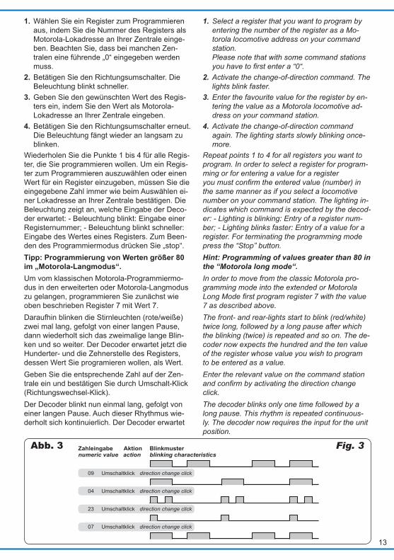
Umschaltklick
Umschaltklick
Umschaltklick
Umschaltklick
09
04
23
07
Zahleingabe Aktion Blinkmuster
direction change click
direction change click
direction change click
direction change click
numeric value action blinking characteristicsFig. 3Abb. 3
1. Wählen Sie ein Register zum Programmieren aus, indem Sie die Nummer des Registers als Motorola-Lokadresse an Ihrer Zentrale einge-ben. Beachten Sie, dass bei manchen Zen-tralen eine führende „0“ eingegeben werden muss.
2. Betätigen Sie den Richtungsumschalter. Die Beleuchtung blinkt schneller.
3. Geben Sie den gewünschten Wert des Regis-ters ein, indem Sie den Wert als Motorola- Lokadresse an Ihrer Zentrale eingeben.
4. Betätigen Sie den Richtungsumschalter erneut. Die Beleuchtung fängt wieder an langsam zu blinken.
Wiederholen Sie die Punkte 1 bis 4 für alle Regis-ter, die Sie programmieren wollen. Um ein Regis-ter zum Programmieren auszuwählen oder einen Wert für ein Register einzugeben, müssen Sie die eingegebene Zahl immer wie beim Auswählen ei-ner Lokadresse an Ihrer Zentrale bestätigen. Die Beleuchtung zeigt an, welche Eingabe der Deco-der erwartet: - Beleuchtung blinkt: Eingabe einer Registernummer; - Beleuchtung blinkt schneller: Eingabe des Wertes eines Registers. Zum Been-den des Programmiermodus drücken Sie „stop“.Tipp: Programmierung von Werten größer 80 im „Motorola-Langmodus“.Um vom klassischen Motorola-Programmiermo-dus in den erweiterten oder Motorola-Langmodus zu gelangen, programmieren Sie zunächst wie oben beschrieben Register 7 mit Wert 7. Daraufhin blinken die Stirnleuchten (rote/weiße) zwei mal lang, gefolgt von einer langen Pause, dann wiederholt sich das zweimalige lange Blin-ken und so weiter. Der Decoder erwartet jetzt die Hunderter- und die Zehnerstelle des Registers, dessen Wert Sie programieren wollen, als Wert.Geben Sie die entsprechende Zahl auf der Zen-trale ein und bestätigen Sie durch Umschalt-Klick (Richtungswechsel-Klick). Der Decoder blinkt nun einmal lang, gefolgt von einer langen Pause. Auch dieser Rhythmus wie-derholt sich kontinuierlich. Der Decoder erwartet
1. Select a register that you want to program by entering the number of the register as a Mo-torola locomotive address on your command station. Please note that with some command stations you have to first enter a “0“.
2. Activate the change-of-direction command. The lights blink faster.
3. Enter the favourite value for the register by en-tering the value as a Motorola locomotive ad-dress on your command station.
4. Activate the change-of-direction command again. The lighting starts slowly blinking once-more.
Repeat points 1 to 4 for all registers you want to program. In order to select a register for program-ming or for entering a value for a register you must confirm the entered value (number) in the same manner as if you select a locomotive number on your command station. The lighting in-dicates which command is expected by the decod-er: - Lighting is blinking: Entry of a register num-ber; - Lighting blinks faster: Entry of a value for a register. For terminating the programming mode press the “Stop” button.Hint: Programming of values greater than 80 in the “Motorola long mode“.In order to move from the classic Motorola pro-gramming mode into the extended or Motorola Long Mode first program register 7 with the value 7 as described above. The front- and rear-lights start to blink (red/white) twice long, followed by a long pause after which the blinking (twice) is repeated and so on. The de-coder now expects the hundred and the ten value of the register whose value you wish to program to be entered as a value. Enter the relevant value on the command station and confirm by activating the direction change click.The decoder blinks only one time followed by a long pause. This rhythm is repeated continuous-ly. The decoder now requires the input for the unit position.
14
Name der CV Name of CV
CV-Nr. CV-No.
Eingabewerte (Default) Value range
Erläuterungen Explanations
Basisadresse / Basic address
1 1 ... 255 (3) Wertebereich bei DCC: 1 ... 127 Range of values in DCC: 1 ... 127
Hinweis: Wenn für die Basisadr. ein Wert > 127 programmiert wird und die Verwendung erweit-erter Adr. in CV 29 ausge schaltet ist, reagiert der Decoder nicht auf DCC-Befehle.
Hint: If a value > 127 is set for the basic address and the use of enlarged addresses in CV 29 is set to off, the decoder does not react to signals in DCC format!
Startspannung / Starting voltage
2 0 ... 63 (6) Spannung, die bei Fahr stufe 1 an den Motor aus gegeben wird. Der Wert ist spezifisch angepasst und sollte nicht geändert werden.
Output voltage at speed level 1 to the motor. The value is optimised to the integrated motor and should not be changed.
Beschleunigungs-rate / Acceleration rate
3 0 ... 63 (10) Wartezeit, die beim Beschleunigen der Lok jeweils vor dem Hochschalten zur nächst höheren Fahrstufe vergeht. Berechnung: Zeit zw. min. und max. Fahrstufe = Wert von CV3 x 1,785 sec.
Delay before the switching to the next higher speed level when the loco is accelerating. Calculation as follows: time between min. and max. speed steps = value of CV3 x 1,785 sec.
Bremsrate / Deceleration rate
4 0 ... 63 (8) Wartezeit, die beim Abbremsen der Lok jeweils vor dem Herunter schalten zur nächst niedrigeren Fahrstufe vergeht. Berechnung wie unter CV3.
Delay before the switching to the next lower speed level when the locomotive is braking. The delay is calculated as described in CV3.
jetzt die Einerstelle des Registers. Geben Sie die entsprechende Zahl auf der Zen-trale ein und bestätigen Sie durch Umschalt-Klick. Jetzt ist dem Decoder der „Name“ des Registers bekannt, nun folgt der Inhalt.Dies signalisiert der Decoder durch zweimaliges kurzes Blinken, gefolgt von einer langen Pause. Geben Sie wieder die Hunderter und Zehnerstelle ein und bestätigen Sie durch Umschalt-Klick.Der Decoder zeigt durch kurzes Blinken, gefolgt von langer Pause, dass er die Einerstelle des Wertes erwartet.Beispiel: In Register 94 soll der Wert 237 einge-tragen werden. Der Decoder soll sich bereits für dieses Beispiel im Langmodus befinden – umge-schaltet durch das klassische Motorola-Program-mierverfahren mittels Register 7.Das Abschalten der Gleisspannung oder ein Fahr-befehl auf die Adresse des Decoders beendet je-den Programmiermodus.
5.4 Konfigurationsvariablen (CV)In der Tabelle sind alle Konfigurationsvariablen (für das DCC-Format) und Register (für das Moto-rola-Format) aufgeführt, die für den Stopfexpress eingestellt werden können.In der Tabelle sind in der Spalte „CV-Nr./Register“ die identischen Nummern der Konfigurationsvaria-blen für die Programmierung im DCC-Format und Register für die Programmierung im Motorola-For-mat angegeben. Die Defaultwerte sind die Werte, die bei Auslieferung eingestellt sind und die nach einem Reset eingestellt werden (siehe CV 8). Hinweis: Für einige Konfigurationsvariablen wer-den die Eingabewerte durch Addieren der Zah-lenwerte ermittelt, die den gewünschten Einstel-lungen entsprechen.
Enter the relevant value on the command station and confirm by activating the change-of-direction command.Now the decoder knows the “name” of the register after which follows the content.The decoder indicates it by two short blinks fol-lowed by a long pause. Again enter the hundred and decade and confirm by activating the change-of-direction command.The decoder indicates to receive the value for the unit position by short blinking followed by a long pause.Example: You want to enter the value 237 in regis-ter 94. Let´s assume the decoder is already in the “long mode” for this example – arrived at by the classic Motorola programming method by means of register 7.Turning off the track voltage or a command to the address of the decoder terminates the program-ming mode.
5.4 Configuration variables (CVs)
The table contains all configuration variables (for the DCC format) and register (for the Motorola format) that can be adjusted for the tamping ma-chine.In the table the column “CV-No./Register” shows the identical numbers of the configuration varia-bles for programming in the DCC format and the register for programming in the Motorola format. The default values are the factory set values that will also be applied after a decoder reset (refer to CV 8).
Hint: For some configuration variables the values to be entered are calculated by adding the num-bers corresponding to the favourite settings.
15
Name der CV Name of CV
CV-Nr. CV-No.
Eingabewerte (Default) Value range
Erläuterungen Explanations
Versionsnummer / Version number
7 (1) Nur lesbar / Motorola (erweiterte Programmierung. Schreiben von Wert 8 ermöglicht erweiterte Programmierung unter Motorola.
Read only! / Motorola (extended programming): Writing of value 8 allows extended programming in motorola protocol.
Hersteller / Manufacturer
8 (109) Nur lesbar / Reset Werkseinstellungen Schreiben von Wert 8 setzt alle Werte auf Auslieferungszustand zurück. Schreiben von Wert 9 setzt alle Werte außer Lokadresse, CV 29 und Fahrstufen-tabelle auf Auslieferungszustand zurück.
Read only! / factory reset Writing a value of 8 resets all CVs to the factory settings. Writing 9 resets all CVs except the ad-dress, CV 29 and the speed step table.
Zwangsbremsung / Packet time out value
11 0 ... 255 (100) Autom. Halt bei Signalausfall von der Digitalzentrale. Berechnung: Wert x 0,1 = Zeit [sec] bis Stop-Auslösung.
Contains the maximum time period that the decoder will maintain its speed without receiving a valid packet addressed to it.
Erweiterte Adresse / Extended address
17 18
192 ... 231 (0) 0 ... 255 (0)
Nur für DCC. Bei den meisten Zentralen ist es möglich, erweiterte Adressen direkt einzugeben. Die CVs 17, 18 und 29 werden von der Zentrale automatisch richtig eingestellt.
Only for DCC format. Most command stations permit entering long addresses directly. In this case the CVs 17, 18 and 29 are set automatically to the proper values.
Mehrfachtraktions-adresse / Multi-unit address
19 0 ... 127 (0) 2. Adresse. 2nd adress.
Bremsverhalten bei Gleichspannung / Decoder automatic stopping configura-tion
27 0, 16 , 32 (16) Kein Bremsen bei Gleichspg. = 0 Bremsen bei Gleichspg. in Gegenricht. = 16 Bremsen bei Gleichspg. in Fahrtricht. = 32
No braking with DC = 0Braking with DC in reverse dir. = 16Braking with DC in actual dir. = 32
Hinweis: Standardmäßig wird bei Anliegen einer Gleichspg. am Gleis in den Analogbetrieb umgeschaltet. Setzen Sie den Decoder auf einer Anlage mit einer Bremsstrecke ein, die auf dem Anlegen einer Gleichspg. basiert (z. B. Märklin-Bremsstrecke), muss das Umschalten auf Analogbetrieb verhindert und sichergestellt werden, dass die Lok wie gewünscht auf die Bremsstrecke reagiert. Wird für den Decoder ein Bremsen bei positiver oder negativer Gleichspg. eingestellt, wird automatisch die Analogerken-nung ausgeschaltet.
Hint: It is standard to switch over into analogue mode when applying a DC voltage at the rails. In case that the decoder is run in a layout with a braking route based on applying a DC voltage (e. g. Märklin-brake distance), the locomotive has to be prevented from changing over into analogue mode and it has to be ensured that the locomotive reacts as expected on the braking route.When braking with positive or negative DC voltage is set for the decoder, the analogue recognition is switched off automatically.
RailCom / RailCom
28 0 ... 3 (3) Bidirektionale Kommunikation: inaktiv = 0, Adresse senden aktiv = 1, Quittung und POM aktiv = 2
Bi-directional communication: inactive = 0, address broadcast enabled = 1, acknowledge and PoM enabled = 2
Konfiguration / Configuration
29 (14) Bit0: 0: Fahrtrichtung normal, 1: Fahrtrich-tung invertiert, Bit1: 0: 14 Fahrstufen, 1: 28 / 128 Fahrstufen, Bit2: 0: Analogbetrieb nicht erlaubt, 1: Analogbetrieb erlaubt, Bit3: 0: RailCom nicht erlaubt, 1: RailCom erlaubt, Bit5: 0: kurze Adresse in CV1, 1: lange Adresse in CV17 – CV18
Bit0: 0: direction normal, 1: direction inverted, Bit1: 0: 14 speed steps, 1: 28 / 128 speed steps, Bit2: 0: no analogue operation, 1: analogue operation allowed, Bit3: 0: No RailCom, 1: RailCom allowed, Bit5: 0: short address in CV1, 1: long address in CV17 – CV18
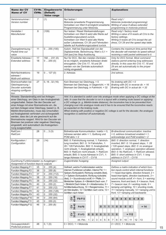
Zuordnung Funktionstasten zu Ausgängen / Assignment of function keys to outputs
Zugeordneter Ausgang: Assigned output:
Function Mapping F1 35 0 ... 255 (4) Definiert, welche Funktionstasten welche internen Funktionen schalten. Interne Fkt: 1 = Spitzen-/Schlusslicht, Richtung vorwärts (fest), 2 = Spitzen-/Schlusslicht, Richtung rückwärts (fest), 3 = Soundmodul on/off, 4 = Pfeife, 5 = Blinklichter Spitzen, 6 = Blinklicht Dach vorn, 7 = Blinklicht Dach hinten, 8 = Arbeitsmodus, 9 = Schlittenbeleuchtung, 10 = Rangiermodus, 11 = ein Mal stopfen, 12 = Schlitten nach vorne, 13 = Schlitten nach hinten
Defines a matrix indication of which func-tion inputs control which internal functions: 1 = head-/rear-lights, direction forward, 2 = head-/rear-lights, direction backwards, 3 = sound module on/off, 4 = horn, 5 = warning beacons, front and back, 6 = beacon, front, 7 = beacon rear, 8 = working mode, 9 = tamping unit lighting, 10 = shunting mode, 11 = tamping manually, 12 = tamping unit to front, 13 = tamping unit backwards
Function Mapping F2 36 0 ... 255 (8)Function Mapping F3 37 0 ... 255 (112)Function Mapping F4 38 0 ... 255 (16)Function Mapping F5 39 0 ... 255 (32)Function Mapping F6 40 0 ... 255 (2)Function Mapping F7 41 0 ... 255 (12)Function Mapping F8 42 0 ... 255 (128)Function Mapping F9 43 0 ... 255 (32)Function Mapping F10 44 0 ... 255 (64)Function Mapping F11 45 0 ... 255 (0)Function Mapping F12 46 0 ... 255 (8)
Vorzugsprotokoll / Preferred protocol
48 0, 1 (0) 0 = DCC; 1 = Motorola 0 = DCC; 1 = Motorola
0 0 0 0 1 1 1 0CV
33-3
7
F1-F3
CV
38-4
2
F4-F8
CV
43-4
6
F9-F12
int. Fkt.: 1 2 3 4 5 6 7 8 9 10 11 12 13
0 1 1 1 0 0 0 0
X X X X X X X X
= 112
= 14
16
Name der CV Name of CV
CV-Nr. CV-No.
Eingabewerte (Default) Value range
Erläuterungen Explanations
Multiprotokoll / Multi protocol
49 0 ... 100 (50) Wenn der Stopfexpress nicht mehr unter seinem bisherigen Protokoll adressiert wird, dann versucht er das alternative Protokoll. Er kann während des Betriebs zwischen DCC und MM umschalten. Die Zeit ist 0.1 Sekunden * CV (Bsp.: Wert 20 = 2 Sek.). Wenn der Stopfexpress eine Adresse auch im alternativen Protokoll nicht findet, dann wird er gestoppt. Wert 0 bedeutet, dass diese Funktion nicht aktiv ist und der Stopfexpress während des Betriebs das Protokoll nicht wechselt. Einige Zentralen, z.B. EcoS, adressieren gestoppte Loks nicht dauerhaft. In solchen Fällen ist es empfehlenswert diese CV auf 0 zu setzen.
If the tamping machine is no longer addressed in its current digital protocol for a time period, it tries the alternative, by switching between DCC and MM. The time is 0.1 seconds * CV 49 (e. g. a value of 20 = 2 seconds). If the tamping machine is not addressed even in the alternative protocol, it stops. A value of 0 means this function is not active, and the tamping machine does not switch protocols while in operation. Some digital stations, e. g. the EcoS, do not address stopped locomotives periodically, in this case it is recommended to set this CV to 0.
Lastregelparam. KP Param. load control
51 0 ... 255 (250) = Proportionaler Anteil der Lastregelung Abstimmung ab Werk optimiert
= Proportional component of the load control optimised by factory set.
Lastregelparam. KI Param. load control
52 0 ... 255 (30) = Integraler Anteil der Lastregelung. Abstimmung ab Werk optimiert
= Integral component of the load control optimised by factory set.
Lastregelparam. KD Param. load control
53 0 ... 255 (50) = Differentieller Anteil der Lastregelung. Abstimmung ab Werk optimiert
= Differential component of the load control optimised by factory set.
Synchronisation / Synchronisation
54 0 ... 255 (180) Synchronisation zwischen den beiden Motoren für Fahrt und Schlitteneinheit. Diesen Wert nicht ändern!
Synchronisation between the two motors. It is generally not required to change this value.
Analogbetrieb: Untere Gleisspan-nungsschwelle f. Motorbetrieb / Analogue operation: upper voltage level for motor
56 0 ... 255 (150) Leistungsstarke Trafos erlauben u.U. etwas kleinere Werte, damit ist eventuell eine Verbesserung der Langsamfahrt im Analogbetrieb erreichbar.
Some more powerful transformers allow smaller values, leading to a smoother control of low speeds in analogue mode.
Analogbetrieb: Obere Gleisspan-nungsschwelle f. Motorbetrieb / Analogue Operation: Upper voltage level for motor
57 0 ... 255 (165) Wie bei CV 56. Der Wert dieser CV sollte um ca. 10 – 20 größer sein als der Wert in CV 56. Je höher der Wert, desto später startet die Maschine bei Aufdrehen des analogen Fahrreglers.
As CV 56. This value should be 10 – 20 higher than CV 56. Higher values mean the motor starts later when the voltage controller is turned higher.
Analogbetrieb: Untere Gleisspan-nungsschwelle f. Soundbetrieb / Analogue operation: lower voltage level for sound
58 0 ... 255 (140) Leistungsstarke Trafos erlauben u.U. etwas kleinere Werte, damit ist eventuell ein früherer Start des Sounds im Analog-betrieb erreichbar.
Some more powerful transformers allow smaller values, so the sound can be started on smaller voltage levels.
Analogbetrieb: Obere Gleisspan-nungsschwelle f. Sound / Analogue operation: upper volt-age level for sound
59 0 ... 255 (150) Wie bei CV 58. As CV 58.
Motorola Funktionsadresse / Motorola function address
61 0 ... 255 (0) Durch Eingabe einer beliebigen Adresse werden die Funktionen F1 – F4 für diese Motorola-Adresse als Funktionen F5 – F8 gewertet. So kann man 8 Funktionen auf-rufen, auch mit Zentralen die nur 4 Funkti-onen pro Lokomotive schalten können.
Setting an address in this CV allows the functions F1 – F4 for this loco address to be used as functions F5 – F8. This feature makes it possible to use 8 func-tions even with digital stations which can control only 4 functions.
Lautstärke / Volume
63 0 ... 100 (100) Höhere Werte = höhere Lautstärke. Wert 0 bedeutet Lautstärkeeinstellung d. Poti.
Higher values = higher volume. Value 0 means setting the volume with poti.
Fahrstufentabelle / Speed table
67-94 0 ... 255 Abstimmung ab Werk optimiert Optimised by factory set.
5.5 Lautstärke manuell einstellen Im Digitalbetrieb erfolgt die Lautstärkeeinstellung über die CV 63 (vgl. Tabelle oben). Im Analogbe-trieb erfolgt die Lautstärkeeinstellung über ein Po-tenziometer, welches im Dachbereich unterge-bracht ist. Die Stellung des Potenziometers spielt im Digitalbetrieb keine Rolle (außer CV 63 = 0).
5.5 Adjusting the volume manually
In digital mode the volume is adjusted by setting CV 63 (compare with table above). In analogue mode the volume is adjusted with a potentiome-ter located in the roof area. The setting of this po-tentiometer has no effect in digital mode (except CV 63 = 0).
17
Kleinen Schraubendreher benutzen!Use a small screwdriver!
Fig. 4Abb. 4
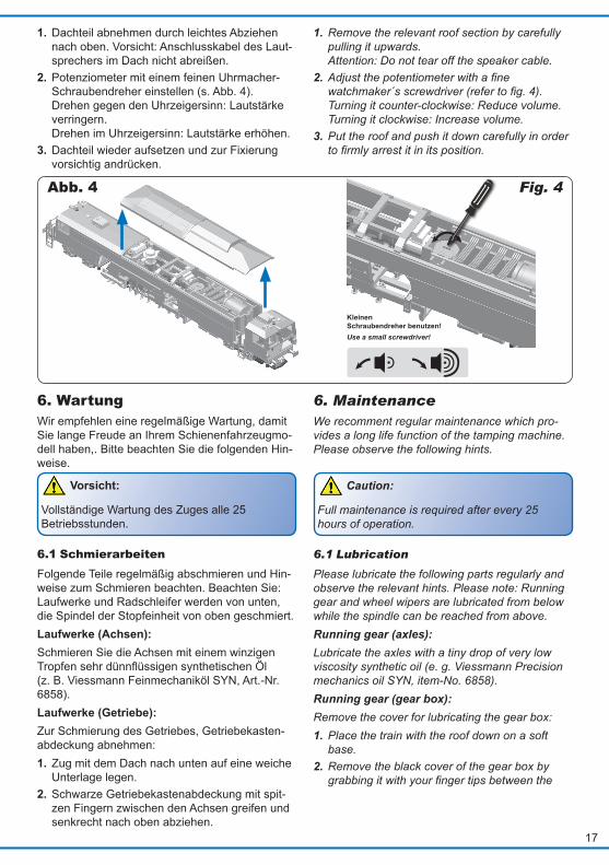
1. Dachteil abnehmen durch leichtes Abziehen nach oben. Vorsicht: Anschlusskabel des Laut-sprechers im Dach nicht abreißen.
2. Potenziometer mit einem feinen Uhrmacher-Schraubendreher einstellen (s. Abb. 4). Drehen gegen den Uhrzeigersinn: Lautstärke verringern. Drehen im Uhrzeigersinn: Lautstärke erhöhen.
3. Dachteil wieder aufsetzen und zur Fixierung vorsichtig andrücken.
1. Remove the relevant roof section by carefully pulling it upwards. Attention: Do not tear off the speaker cable.
2. Adjust the potentiometer with a fine watchmaker´s screwdriver (refer to fig. 4). Turning it counter-clockwise: Reduce volume. Turning it clockwise: Increase volume.
3. Put the roof and push it down carefully in order to firmly arrest it in its position.
6. Wartung Wir empfehlen eine regelmäßige Wartung, damit Sie lange Freude an Ihrem Schienenfahrzeugmo-dell haben,. Bitte beachten Sie die folgenden Hin-weise.
Vorsicht:
Vollständige Wartung des Zuges alle 25 Betriebsstunden.
6.1 Schmierarbeiten Folgende Teile regelmäßig abschmieren und Hin-weise zum Schmieren beachten. Beachten Sie: Laufwerke und Radschleifer werden von unten, die Spindel der Stopfeinheit von oben geschmiert. Laufwerke (Achsen): Schmieren Sie die Achsen mit einem winzigen Tropfen sehr dünnflüssigen synthetischen Öl (z. B. Viessmann Feinmechaniköl SYN, Art.-Nr. 6858). Laufwerke (Getriebe): Zur Schmierung des Getriebes, Getriebekasten-abdeckung abnehmen: 1. Zug mit dem Dach nach unten auf eine weiche
Unterlage legen. 2. Schwarze Getriebekastenabdeckung mit spit-
zen Fingern zwischen den Achsen greifen und senkrecht nach oben abziehen.
6. Maintenance We recomment regular maintenance which pro-vides a long life function of the tamping machine. Please observe the following hints.
Caution:
Full maintenance is required after every 25 hours of operation.
6.1 Lubrication
Please lubricate the following parts regularly and observe the relevant hints. Please note: Running gear and wheel wipers are lubricated from below while the spindle can be reached from above. Running gear (axles): Lubricate the axles with a tiny drop of very low viscosity synthetic oil (e. g. Viessmann Precision mechanics oil SYN, item-No. 6858). Running gear (gear box): Remove the cover for lubricating the gear box:1. Place the train with the roof down on a soft
base. 2. Remove the black cover of the gear box by
grabbing it with your finger tips between the
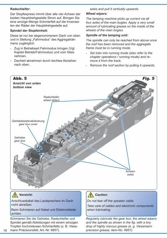
18
Fig. 5Abb. 5
Getriebekastenabdeckunggear box cover
Ansicht von untenbottom view
Achsenaxles
Radschleiferwheel sliders
Getriebegear box
Radschleifer: Der Stopfexpress nimmt über alle vier Achsen der beiden Hauptdrehgestelle Strom auf. Bringen Sie eine winzige Menge Schmierfett auf die Innensei-ten der Räder der Hauptdrehgestelle auf. Spindel der Stopfeinheit: Diese ist nur bei abgenommenem Dach von oben und in Stellung „Fahrmodus“ des Aggregatrah-mens zugänglich. - Zug in Betriebsart Fahrmodus bringen (Vgl.
Kapitel Betrieb/Fahrmodus) und vom Gleis nehmen.
- Dachteil abnehmen durch leichtes Abziehen nach oben.
axles and pull it vertically upwards.Wheel wipers: The tamping machine picks up current via all four axles of the main bogies. Apply a very small amount of lubricating grease on the inside of the wheels of the main bogies.Spindle of the tamping unit: The spindle can only be reached from above once the roof has been removed and the aggregate frame must be in running mode. - Set train into running mode (also refer to the
chapter operations / running mode) and re-move it from the track.
- Remove the roof section by pulling it upwards.
Vorsicht:
Anschlusskabel des Lautsprechers im Dach nicht abreißen. Beim Schmieren auf Kabel und Elektronikteile achten.
Schmieren Sie die Getriebe, Radschleifer und Spindel gemäß Abbildungen mit einem winzigen Tropfen hochviskosen Schmierfetts (z. B. Viess-mann Präzisionsfett, Art.-Nr. 6857).
Caution:
Do not tear off the speaker cable. Take care of cables and electronic components when lubricating.
Regularly lubricate the gear box, the wheel wipers and the spindle as shown in the fig. with a tiny drop of highly viscous grease (e. g. Viessmann precision grease, item-No. 6857).
19
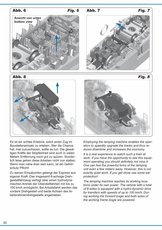
6.2 Mechanische ÜberprüfungKontrollieren Sie die Gängigkeit von Stopfeinrich-tung und Schlitteneinheit. Alle Teile der Stopfmechanik (Aggregatrahmen und Stopfeinheit) müssen freigängig seitlich pen-deln können. Kontrollieren Sie, ob alle Stopfmeißel an der Stopfeinheit vorhanden sind. Sollten einer oder mehrere Stopfmeißel abgebrochen sein, können Sie diese austauschen. Stopfmeißel austauschen (Abb. 6)Falls im harten Alltagsbetrieb einmal die Stopf-meißel abgenutzt oder abgebrochen sein sollten, können Sie diese durch neue Meißel ersetzen. Im mitgelieferten Zubehörbeutel finden Sie einige Er-satzmeißel. - Zug mit dem Dach auf eine weiche Unterlage
legen. - Stopfeinheit mit einer Hand beidseitig seitlich
festhalten. - Alten Stopfmeißel mit spitzer Zange vorsichtig
aus der Halterung ziehen. - Neuen Stopfmeißel vorsichtig in die Halterung
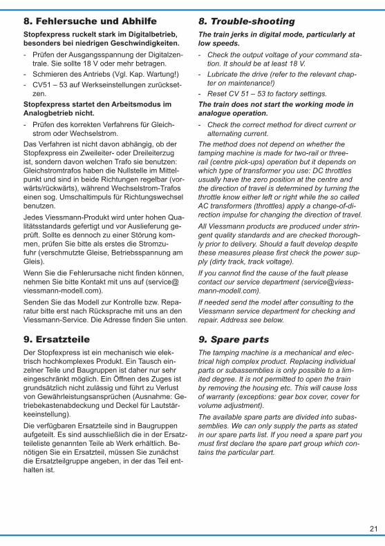
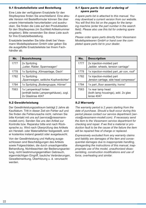
stecken. Haftreifentausch (Abb. 7 + 8) Da Haftreifen altern, sollten Sie diese bei sicht-baren Abnutzungserscheinungen auswechseln. Im Zubehörbeutel finden Sie einige Ersatz-Haft-reifen. Achten Sie bei der Montage darauf, dass Sie die Haftreifen gleichmäßig und ohne Verspannungen aufziehen, um einen unrunden Lauf des Modells zu vermeiden.Haftreifen entfernen durch seitliches Abschieben vom Rad. Evtl. einen Uhrmacher-Schraubendre-her oder eine spitze Zange zu Hilfe nehmen. Neuen Haftreifen aufziehen. Haftreifen ansetzen und mit Hilfe einer flachen Klinge (z. B. Uhrma-cher-Schraubendreher) vorsichtig rundum aufzie-hen.
7. Vorbild Der Schienenstopfexpress 09-3X des österrei-chischen Bahntechnikunternehmens Plasser & Theurer ist weltweit mit mehr als 600 Exemplaren im Einsatz. Er dient der präzisen Stopfung des aufgearbeiteten Bettungsmaterials. Eine ideale Verdichtung des Schottermaterials sorgt für per-fekte Gleislage und einen langfristig stabilen und wartungsarmen Gleiskörper. Der Einsatz eines Stopfexpress ermöglicht die schnelle Bearbeitung einer Strecke und reduziert so Sperrzeiten bei hoher Wirtschaftlichkeit.
6.2 Mechanical check
Check the free-running of the tamping unit and the sled. All parts of the tamping mechanism (aggregate frame and tamping unit) must be able to freely swing sideways. Check if all bits of the tamping unit are in place. Should one or more of the bits have been broken they can be replaced.
Exchanging bits (fig. 6) Should the bits have been worn down or broken in the rough daily routine you may replace them with new bits. Some spare bits are supplied with the accessories. - Place the train on its roof on a soft base. - Hold both sides of the tamping unit with one hand. - Remove the old bit with pointed pliers by care-
fully pulling them from their carrier.- Carefully insert the new bit into the carrier. Replacing traction tyres (fig. 7 + 8) Since traction tyres are subject to wear and tear you should replace them once their wear down becomes noticeable. There are some spare trac-tion tyres in the accessories pouch.Please take care to mount the traction tyres equal and without any undue tension in order to assure smooth running.Remove the traction tyres by pushing them side-ways off the wheel. Perhaps use a watchmaker´s screwdriver or pointed pliers for this purpose. Mount the new traction tyres by placing them with the aid of a knife edge or similar (e. g. watchmaker´s screwdriver) and carefully pull them onto the wheel.
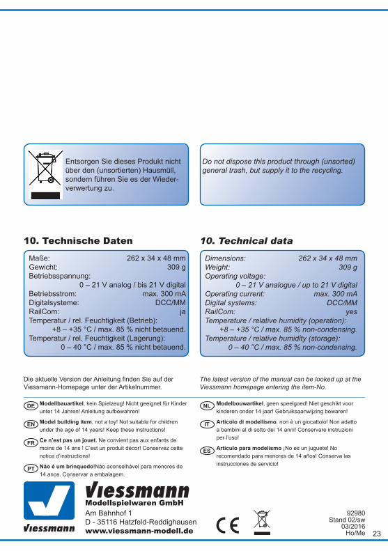
7. Prototype There are more than 600 units of the tamping machine “Schienenstopfexpress 09-3X“ by the Austrian company Plasser & Theurer – a manu-facturer of track maintenance equipment - world-wide. It serves for precise tamping of the reworked ballast. The ideal compaction of the ballast pro-vides a perfect position and level of the track and a stable and low-on-maintenance track body over long periods of time.
20
Fig. 8Abb. 8
Fig. 6Abb. 6 Abb. 7 Fig. 7
Ansicht von untenbottom view
Es ist ein echtes Erlebnis, solch einen Zug im Baustelleneinsatz zu erleben. Wer die Chance hat, mal zuzuschauen, sollte es tun: Die gewal-tigen Kräfte der Stopfeinheit sind auch in vielen Metern Entfernung noch gut zu spüren. Sonder-lich leise gehen diese Arbeiten nicht von statten. Wenn man nahe dran sein kann, ist ein Gehör-schutz Pflicht! Zu seinen Einsatzorten gelangt der Express aus eigener Kraft. Das insgesamt 6-achsige Dreh-gestellfahrzeug verfügt über einen hydrodyna-mischen Antrieb der Überstellfahrten mit bis zu 100 km/h ermöglicht. Bei Arbeitsfahrt werden das vordere Drehgestell und beide Achsen des Ar-beitsrahmendrehgestells angetrieben.
Employing the tamping machine enables the oper-ators to speedily upgrade the tracks and thus re-duces downtime and increases the economy.It is a real experience to watch such a train at work. If you have the opportunity to see this equip-ment operating you should definitely not miss it: One can feel the powerful force of the tamping unit even a few meters away. However, this is not exactly quiet work. If you get close use some ear protection!The tamping machine reaches its working loca-tions under its own power. The vehicle with a total of 6-axles is equipped with a hydro-dynamic drive for transfers with speeds of up to 100 km/h. Dur-ing working the forward bogie and both axles of the working frame bogie are powered.
21
8. Fehlersuche und Abhilfe Stopfexpress ruckelt stark im Digitalbetrieb, besonders bei niedrigen Geschwindigkeiten. - Prüfen der Ausgangsspannung der Digitalzen-
trale. Sie sollte 18 V oder mehr betragen. - Schmieren des Antriebs (Vgl. Kap. Wartung!) - CV51 – 53 auf Werkseinstellungen zurückset-
zen. Stopfexpress startet den Arbeitsmodus im Analogbetrieb nicht.- Prüfen des korrekten Verfahrens für Gleich-
strom oder Wechselstrom. Das Verfahren ist nicht davon abhängig, ob der Stopfexpress ein Zweileiter- oder Dreileiterzug ist, sondern davon welchen Trafo sie benutzen: Gleichstromtrafos haben die Nullstelle im Mittel-punkt und sind in beide Richtungen regelbar (vor-wärts/rückwärts), während Wechselstrom-Trafos einen sog. Umschaltimpuls für Richtungswechsel benutzen.Jedes Viessmann-Produkt wird unter hohen Qua-litätsstandards gefertigt und vor Auslieferung ge-prüft. Sollte es dennoch zu einer Störung kom-men, prüfen Sie bitte als erstes die Stromzu-fuhr (verschmutzte Gleise, Betriebsspannung am Gleis). Wenn Sie die Fehlerursache nicht finden können, nehmen Sie bitte Kontakt mit uns auf ([email protected]).Senden Sie das Modell zur Kontrolle bzw. Repa-ratur bitte erst nach Rücksprache mit uns an den Viessmann-Service. Die Adresse finden Sie unten.
9. Ersatzteile Der Stopfexpress ist ein mechanisch wie elek-trisch hochkomplexes Produkt. Ein Tausch ein-zelner Teile und Baugruppen ist daher nur sehr eingeschränkt möglich. Ein Öffnen des Zuges ist grundsätzlich nicht zulässig und führt zu Verlust von Gewährleistungsansprüchen (Ausnahme: Ge-triebekastenabdeckung und Deckel für Lautstär-keeinstellung). Die verfügbaren Ersatzteile sind in Baugruppen aufgeteilt. Es sind ausschließlich die in der Ersatz-teileliste genannten Teile ab Werk erhältlich. Be-nötigen Sie ein Ersatzteil, müssen Sie zunächst die Ersatzteilgruppe angeben, in der das Teil ent-halten ist.
8. Trouble-shooting The train jerks in digital mode, particularly at low speeds. - Check the output voltage of your command sta-
tion. It should be at least 18 V. - Lubricate the drive (refer to the relevant chap-
ter on maintenance!) - Reset CV 51 – 53 to factory settings.The train does not start the working mode in analogue operation.- Check the correct method for direct current or
alternating current. The method does not depend on whether the tamping machine is made for two-rail or three-rail (centre pick-ups) operation but it depends on which type of transformer you use: DC throttles usually have the zero position at the centre and the direction of travel is determined by turning the throttle know either left or right while the so called AC transformers (throttles) apply a change-of-di-rection impulse for changing the direction of travel.All Viessmann products are produced under strin-gent quality standards and are checked thorough-ly prior to delivery. Should a fault develop despite these measures please first check the power sup-ply (dirty track, track voltage).If you cannot find the cause of the fault please contact our service department ([email protected]). If needed send the model after consulting to the Viessmann service department for checking and repair. Address see below.
9. Spare parts The tamping machine is a mechanical and elec-trical high complex product. Replacing individual parts or subassemblies is only possible to a lim-ited degree. It is not permitted to open the train by removing the housing etc. This will cause loss of warranty (exceptions: gear box cover, cover for volume adjustment).The available spare parts are divided into subas-semblies. We can only supply the parts as stated in our spare parts list. If you need a spare part you must first declare the spare part group which con-tains the particular part.
22
9.1 Ersatzteileliste und BestellungEine Liste der verfügbaren Ersatzteile für den Stopfexpress finden Sie anschließend. Eine aktu-elle Version mit Bestellformular können Sie über unsere Internetseite herunterladen und ausdru-cken. Sie finden die Liste auf den Produktseiten für den Stopfexpress (im Suchfeld Artikelnummer eingeben). Bitte verwenden Sie diese Liste auch für Ihre Ersatzteilbestellung. Ersatzteile bestellen Sie bitte direkt bei Viess-mann Modellspielwaren GmbH oder geben Sie die ausgefüllte Ersatzteileliste bei Ihrem Fach-händler ab.
Nr. Bezeichnung1777 2x Spritzling
„Leiter, Räder, Spannwagen“
1778 1x Spritzling „Klimaanlage, Dach“
1782 1x Spritzling „Spannwagen, seitliche Kopfverdichter“
1784 1x Spritzling „Bodengruppe, Hörner“
7063 1x Lampenkopf hinten (enthält beide Lampengehäuse), zzgl. 2x Glaslinse 4047
9.2 Gewährleistung Der Gewährleistungszeitraum beträgt 2 Jahre ab Kaufdatum. Tritt in dieser Zeit ein Fehler auf und Sie finden die Fehlerursache nicht, nehmen Sie bitte Kontakt mit uns auf ([email protected]). Senden Sie uns den Artikel zur Kontrolle bzw. Reparatur bitte erst nach Rück-sprache zu. Wird nach Überprüfung des Artikels ein Herstell- oder Materialfehler festgestellt, wird er kostenlos instand gesetzt oder ausgetauscht.Von der Gewährleistung und Haftung ausge-schlossen sind Beschädigungen des Artikels sowie Folgeschäden, die durch unsachgemäße Behandlung, Nichtbeachten der Bedienungsanlei-tung, nicht bestimmungsgemäßen Gebrauch, eigenmächtigen Eingriff, bauliche Veränderungen, Gewalteinwirkung, Überhitzung u. ä. verursacht werden.
9.1 Spare parts list and ordering of spare parts
A spare parts list is attached to this manual. You may download a current version from our website. You will find this list on the pages for the tamp-ing machine (enter the part number in the search field). Please also use this list for ordering spare parts. Please order spare parts directly from Viessmann Modellspielwaren GmbH or hand over the com-pleted spare parts list to your dealer.
No. Description1777 2x injection-molded part
„ladder, wheels, tension carriage“
1778 1x injection-molded part „air con, roof“
1782 1x injection-molded part „tension carriage, side head compressor“
1784 1x part „floor assembly, horns“
7063 1x rear lamp head (both lamp housings), add. 2x glas lense 4047
9.2 Warranty
The warranty period is 2 years starting from the date of purchase. Should a fault occur during this period please contact our service department ([email protected]). If necessary send the item to the Viessmann service department for checking and repair. If we find a material or pro-duction fault to be the cause of the failure the item will be repaired free of charge or replaced.Expressively excluded from any warranty claims and liability are damages of the item and conse-quential damages due to inappropriate handling, disregarding the instructions of this manual, inap-propriate use of the model, unauthorized disas-sembling, construction modifications and use of force, overheating and similar.
Modellbauartikel, kein Spielzeug! Nicht geeignet für Kinder unter 14 Jahren! Anleitung aufbewahren!
Model building item, not a toy! Not suitable for children under the age of 14 years! Keep these instructions!
Ce n’est pas un jouet. Ne convient pas aux enfants de moins de 14 ans ! C’est un produit décor! Conservez cette notice d’instructions!
Não é um brinquedo!Não aconselhável para menores de 14 anos. Conservar a embalagem.
Modelbouwartikel, geen speelgoed! Niet geschikt voor kinderen onder 14 jaar! Gebruiksaanwijzing bewaren!
Articolo di modellismo, non è un giocattolo! Non adatto a bambini al di sotto dei 14 anni! Conservare instruzioni per l’uso!
Artículo para modelismo ¡No es un juguete! No recomendado para menores de 14 años! Conserva las instrucciones de servicio!
DE
EN
FR
NL
IT
ES
PT
Modellspielwaren GmbHAm Bahnhof 1D - 35116 Hatzfeld-Reddighausenwww.viessmann-modell.de 23
Die aktuelle Version der Anleitung finden Sie auf der Viessmann-Homepage unter der Artikelnummer.
The latest version of the manual can be looked up at the Viessmann homepage entering the item-No.
92980 Stand 02/sw
03/2016Ho/Me
10. Technical data
Dimensions: 262 x 34 x 48 mmWeight: 309 gOperating voltage: 0 – 21 V analogue / up to 21 V digitalOperating current: max. 300 mADigital systems: DCC/MM RailCom: yesTemperature / relative humidity (operation): +8 – +35 °C / max. 85 % non-condensing.Temperature / relative humidity (storage): 0 – 40 °C / max. 85 % non-condensing.
10. Technische Daten
Maße: 262 x 34 x 48 mmGewicht: 309 gBetriebsspannung: 0 – 21 V analog / bis 21 V digitalBetriebsstrom: max. 300 mADigitalsysteme: DCC/MM RailCom: jaTemperatur / rel. Feuchtigkeit (Betrieb): +8 – +35 °C / max. 85 % nicht betauend.Temperatur / rel. Feuchtigkeit (Lagerung): 0 – 40 °C / max. 85 % nicht betauend.
Entsorgen Sie dieses Produkt nicht über den (unsortierten) Hausmüll, sondern führen Sie es der Wieder-verwertung zu.
Do not dispose this product through (unsorted) general trash, but supply it to the recycling.

24
Notizen Notes