Embed Size (px)
Citation preview
A DVBS UPnP AV Media Server
Diplomarbeit im StudiengangComputer und Kommunikationstechnik
MichaelChristian Becker
Bearbeitungszeitraum
1. März 2007 1. September 2007
Betreuer: Prof. Dr.Ing. Thorsten Herfet
Gutachter: Prof. Dr.Ing. Thorsten Herfet
Zweitgutachter: Prof. Dr.Ing. Philipp Slusallek
Fachrichtung 6.2 InformatikLehrstuhl für Nachrichtentechnik
Prof. Dr.Ing. Thorsten Herfet

Eidesstattliche Erklärung:Hiermit versichere ich, die vorliegende Arbeit selbstständig und unter ausschliesslicher Verwendung der angegebenen Literatur und Hilfsmittel erstellt zu haben.
Die Arbeit wurde bisher in gleicher oder ähnlicher Form keiner anderen Prüfungsbehörde vorgelegt und auch nicht veröffentlicht.
Saarbrücken, 1. September 2007
_____________________________________
MichaelChristian Becker

Abstract
The goal of this research project is to elaborate and implement a UPnP AV MediaServer that offers DVBS content on a home network. The implementation exploits the UPnP mechanism to describe television framework and live media properties. Therefore one major part of the implementation is the conversion of DVB Service Information and MPEG2 Program Specific Information into the UPnP domain. Hence the DVBS UPnP AV MediaServer presented here is different compared to common UPnP AV MediaServer devices. The scope of the latter is usually restricted to recorded AV content. Extending this common application range the DVBS UPnP MediaServer accomplishes discovery of DVBS Live Media Broadcast services through a UPnP control point. Service selection and service transport are implemented outofband and include provisioning of DVBS hardware with service related parameters.

Contents
Glossary 8
Definition of acronyms 9
Preface 12
1 UPnP Architecture 161.1Introduction to UPnP...............................................................................161.2UPnP Device Architecture......................................................................171.3UPnP AV Architecture............................................................................24
1.3.1Playback Architecture.....................................................................251.3.2Control Point within AV scenario...................................................261.3.3UPnP AV MediaRenderer...............................................................281.3.4UPnP AV MediaServer...................................................................311.3.5ContentDirectory Service...............................................................341.3.6Summary ........................................................................................41
2 DVB Home Network Reference Model 432.1Introduction.............................................................................................432.2Digital Living Network Alliance............................................................432.3DVB Home Network .............................................................................462.4DVBIP ..................................................................................................52
3 DVBS System Overview 623.1Introduction.............................................................................................623.2Modulation and Channel Coding...........................................................633.3MPEG2 Transport Stream.....................................................................65
3.3.1MPEG2 Transport Stream Packet..................................................663.3.2Program Specific information........................................................70
3.4DVB Service Information.......................................................................763.4.1Network Information Table.............................................................783.4.2Service Description Table..............................................................803.4.3Event Information Table.................................................................823.4.4Bouquet Association Table.............................................................853.4.5DVBSI character coding...............................................................863.4.6Summary DVBSI..........................................................................88
4 Mapping DVBSI to UPnP CDS 90
3
4.1Introduction ............................................................................................904.2The DIDLLite XML document............................................................904.3Discussion of the HUAWEI mapping....................................................934.4Discussion results.................................................................................103
4

List of FiguresFigure 1.1: The UPnP Protocol Stack....................................................................19Figure 1.2: MediaRenderer Functional Diagram..................................................31Figure 1.3: MediaServer Functional Diagram......................................................34Figure 1.4: item first order derivatives..................................................................35Figure 1.5: audioItem / videoItem first order derivatives.....................................35Figure 1.6: channelGroup first order derivatives..................................................36Figure 2.1: DLNA Interoperability Guidelines Building Blocks.........................46Figure 2.2: DVBIP Phase 1.3 Home Network Reference Model........................54Figure 3.1: DVBS functional block diagram.......................................................63
6
List of Tables
Table 1.1: Browse() action arguments and related state variables........................38Table 1.2: Search() action arguments and related state variables.........................40Table 2.1: DVBHN Device Categories and Device Classes................................47Table 2.2: SD&S data types and assigned payload ID values..............................56Table 3.1: MPEG2 Transport Stream packet syntax............................................66Table 3.2: PID value assignments.........................................................................67Table 3.3: Adaption_field_control values.............................................................68Table 3.4: Program Association Table syntax.......................................................71Table 3.5: Private section syntax...........................................................................75Table 3.6: DVB Service Information PID and table_id assignments...................77Table 3.7: DVBSI descriptors..............................................................................77Table 3.8: Supported service types........................................................................81Table 3.9: Supported elementary stream types.....................................................81Table 3.10: DVBSI character code tables............................................................86Table 3.11: DVBSI control codes.........................................................................87Table 4.1: HUAWEI mapping DVBSI to UPnP CDS..........................................94Table 4.2: HUAWEI derived mapping DVBSI to UPnP CDS...........................104
7
Glossary
UPnP DVBIPIDVBSSD&SDVBSIMPEG2 PSIContentDirectory service (CDS)HN (Home Network)
8
Definition of acronyms
AN Access Network
AV Audio Video
AVTS UPnP AVTransport Service
BCD Binary Coded Decimal
BCG Broadband Content Guide
BGD Bidirectional Gateway Device
CA Conditional Access
CDS UPnP ContentDirectory Service
CMS UPnP ConnectionManager Service
CoD Content on Demand
CSV Comma Separated Value
DLNA Digital Living Network Alliance
DLNA-DMP DLNA Device Media Player
DLNA-DMR DLNA Device Media Renderer
DLNA-DMS DLNA Device Media Server
DTD Document Type Declaration
DVB Digital Video Broadcasting
GD Gateway Device
GENA Generic Event Notification Architecture
HN Home Network
HNED Home Network End Device
HNN Home Network Node
HTTP Hyper Text Transfer Protocol
IGMP Internet Group Management Protocol
IP Internet Protocol
IPI Internet Protocol Infrastructure
LMB Live Media Broadcast
NSD Network Switch Device
9
NT Notification Type
NTS Notification Sub Type
PVR Personal Video Recorder
QoS Quality of Service
RCS UPnP RenderingControl Service
RD Remote Device
RPC Remote Procedure Call
RTP Real Time Protocol
RTSP Real Time Streaming Protocol
SD&S DVB-IP Service Discovery and Selection
SID Subscription Identifier
SOAP Simple Object Access Protocol
SSDP Simple Service Description Protocol
ST Search Target
TVA TV Anytime
UDA UPnP Device Architecture
UDP User Datagram Protocol
UGD Unidirectional Gateway Device
UPnP Universal Plug and Play
XML eXtensible Markup Language
10

Preface
Motivation
While the deployment of home networks capable of distributing audio/visual content including digital television is rapidly increasing, current UPnP AV MediaServer implementations are limited to the distribution of recorded data. The future significance of both interoperability of digital media devices and the distribution of Digital Television (DTV) services over IPbased networks is confirmed by current efforts to specify appropriate standards. Regarding interoperability we consider the most representative approach to stem from the Digital Living Network Alliance (DLNA), which reuses the UPnP framework. Since UPnP explicitly allocates the means to discover and select DTV services, a user might want to access both recorded and live DTV services through one single device. Therefore we believe there is the necessity for a DVBS UPnP AV MediaServer.
Given the DVBS architecture as source for AV services and respective Service Information (SI), we consider the DVBIP Handbook Version 1.3.1 and the DVBHN Reference Model as the most representative approaches to distribute DTV services over IPbased networks. Hence the analysis of DVBIP and DVBHN in contrast to the architectural conception of the UPnP functionality might be useful to detect analogies and differences for example in both approaches to discover and select AV services.
Outline
Design goals
The software developed in this research project is intended to offer DVBS signals on a home network in a way compatible to the UPnP AV Architecture Framework. Thus the design has to respect several properties inherent to both DVB and UPnP.
The DVBS UPnP AV MediaServer presented here will allow the user to discover and select DVBS services available on the home network. This implies preselection of available DVBS services and therefore processing of DVB Service Information (DVBSI) as well as MPEG2 Program Specific Information (PSI). In order to trace the full spectrum of service related information certain dependencies amongst the DVBSI and PSI table mechanism have to be regarded. Furthermore the DVBS UPnP AV Server model is aware of the given repetition rate constraints for DVBSI and PSI to ensure the integrity of captured data.
12
Complying with the UPnP AV MediaServer device architecture requires the MediaServer model to incorporate the UPnP ContentDirectory Service (CDS) to enable DVBS service discovery for UPnP ControlPoint devices. As UPnP CDS provides the means to describe television framework and live media properties, the model implements a mapping from DVBSI and PSI to corresponding CDS components. The mapping follows the propositions made in [1] as far as the propositions comply with CDS. [1] also suggests several nonstandard extensions to CDS and proposes an alternative use of certain fixedpurpose CDS variables. Due to compatibility reasons with other UPnP devices these propositions are not adopted by the UPnP AV MediaServer model presented here.
The above design goals enable the discovery of DVBS services by any UPnP ControlPoint device. This discovery is usually followed by the selection of a certain service. Since the transport of data, which is described through the use of CDS, is not covered by the UPnP architecture, the transport of DVBS services to a requesting UPnP AV MediaRenderer is a further design goal of the project implementation. Transport in the sense of the project implementation must be understood as generic term that includes several actions. Transport of DVBS signals over a home network starts with the selection of a certain service initiated by the user. This selection must lead to the reception of the appropriate MPEG2 multiprogram Transport Stream (MPTS) and the subsequent extraction of the respective DVBS service portions. Preceding tests with different common software mediaplayers and one hardware mediaplayer showed that the preferred format for MPEG2 data streams is the MPEG2 Program Stream (PS). We therefore consider the transformation of the extracted MPEG2 service portions into a valid MPEG2 PS as indispensable design goal to ensure playback for most mediaplayers.
The DVBS UPnP AV MediaServer implementation reuses and extends existing Linux software that is available under the terms of the GNU General Public License (GPL) and Berkeley Standard Distribution (BSD) License. Regarding Linux as chosen operating system a further design goal for the project implementation is independence of the underlying type of Linux derivative.
All three parts, the processing of DVBSI and PSI, the mapping into the UPnP domain and the transport of DVBS services will finally be merged in a way that the user will only have to run one application that serves as DVBS UPnP AV MediaRenderer.
As last design goal we appoint the validation of the overall implementation with at least one commercial UPnP AV MediaRenderer.
Although the design pays attention to stability and compliance with aforementioned standards, the implementation developed in this research project should be regarded as prototype of a DVBS UPnP AV MediaServer.
13
Structure of this document
Chapter 1 introduces the architectural conception of the UPnP functionality regarding the given research topic. Hence the introduction focuses on the UPnP AV Architecture Framework including the UPnP AV device and service specifications. Chapter 2 gives an overview of the DVBHN Reference Model and DVBIP with respect to the UPnP Architecture. Since the DVBHN Reference Model is designed to merge DVBIP and DLNA capabilities, with the latter being based on the UPnP Architecture, chapter 2 will work out the connection between both approaches.
Chapter 3 discusses prerequisites for the reception of DVBS services in general. What is more chapter 3 explains the usage of DVBSI and PSI in DVB systems. Also it identifies dependencies between the different types of DVBSI and PSI and derives the necessary consequences for implementing the reception of such service information. Chapter 4 briefly explains the mapping between DVBSI and UPnP CDS based on [1] and deduces necessary format and datatype conversions.
Chapter 5 summarizes the project facilities, defining the type of DVB hardware supported by the developed software and introducing the underlying software environment. Chapter 6 deals with the Linux DVB API version 3 and its abilities to access different DVB Device types with respect to the research topic.
Covering the implementation phase, chapter 7 explains the development of a search for available DVBS services and the software that is incorporated and modified for this purpose. Still part of the implementation phase the conversion of DVBSI into CDS is treated in chapter 8. Again the reused software as well as the accomplished modifications are explained. The following chapter 9 gives an overview of the chosen transport mechanism for AV content and explains the mechanism, which is used to transform MPEG2 Transport Streams into MPEG2 Programs Streams. The transformation between both coding standards is further discussed in consideration of one UPnP AV MediaRenderer that was chosen to validate the overall DVBS UPnP AV MediaServer.
14

1 UPnP Architecture
1.1 Introduction to UPnP
The UPnP architecture is maintained by the UPnP Forum1, a consortium comprising over 830 industry members. The UPnP Forum states no restrictions for the application range of UPnP. The work of the UPnP Forum aims towards the seamless connection of any device type like for example entertainment electronics and personal computers. Independent of the underlying network UPnP may be used on top of any of today's physical transmission layers. The basic building blocks of a UPnP network are referred to as devices, services and control points.
Devices
UPnP Devices are modeled as logical containers for services and embedded devices. According to their field of operation, devices are assigned a set of required and optional services. All included services and other properties are visible to control points by means of a standardized XML Device Description. Furthermore the UPnP Forum defines the UPnP Device Architecture (UDA) that specifies the framework which shall allow a device to dynamically join a network, obtain an IP address, announce its capabilities and learn about the presence and the capabilities of other UPnP devices on the network. Furthermore, the UDA cares for the controlled disconnection from the network without leaving an unwanted state behind. The UDA is discussed in greater detail in section 1.2.
Services
Services are the smallest unit of a UPnP network. Services perform their task either dependent on or independent from each other. Their modular design lets services denote an integral part of devices. A service offers control actions that typically have an effect on the state of a service. The overall state of a service may be modeled by one or more state variables. A service within a UPnP device shall maintain a state table, a control server and an event server. Including all state variables, the service's state table models the state of a service. The state table will be updated if state variables change. Changes to state variables may either happen by an action request to the control server or by some internal event. The control server acknowledges action requests and may also allow control points to subscribe for one or more state variables. That is the control point will be automatically informed by the event server upon change of these so called evented state variables.
1 Internet Presence UPnP Forum http://www.upnp.org
16
Similar to a UPnP Device Description the above information about a service is modeled as an XML Service Description with normative character for the UPnP architecture.
As an example a service that is modeling the network resources of an AV content server may predefine its maximum number of possible connected clients through its XML Service Description. Furthermore the service may model its state by means of the state variable NumberOfConnections. In order to internally allocate or to free resources the service may offer the actions Connect() and Disconnect(). By this a control is able to request resources from a server by invoking the Connect() action on the service's control server. If in addition the example network resource service announces the NumberOfConnections state variable as evented, a control point may subscribe for this state variable. From the time of subscription the control point will be asynchronously informed upon change of this particular state variable.
Control Points
In general a UPnP Control Point discovers devices on the network and coordinates their operation by invoking actions on their embedded services. Therefore a Control Point may implement an appropriate User Interface (UI). For an AV scenario a UPnP Control Point also tries to match capabilities of UPnP devices like for example a commonly supported transport protocol or content format. Also a UPnP Control Point allows the user to initiate the AV content flow between matching UPnP Devices that act as source and sink for the chosen content. Note that passive nodes will not interact with each other using UPnP protocols.
1.2 UPnP Device Architecture
The UPnP Device Architecture (UDA) defines six steps of UPnP networking. The first step shall ensure that UPnP Control Points and UPnP Devices obtain an IP address on the network. Step two introduces communication protocols which enable Control Points to discover embedded devices and services. Therefore, UDA choses the third step to explain the description language for both device and service properties, which are separately defined through the respective Templates. Step four deals with the control protocols to be used by Control Points to invoke previously discovered actions on a service. The fifth step of UPnP networking covers the topic eventing, which itself consists of a protocol to enable the subscription to a set of state variables and cancellation of a previous subscription. Furthermore, step five defines the event messages that are sent if a so called evented state variable changes, assuming a Control Point previously subscribed to eventing for the particular state variable. The last step explains a presentation mechanism that may be used to browse any content of a device or even change the state of particular services by means of an HTML based web page, maintained by the device and accessible through any web browser.
17
Protocol Stack
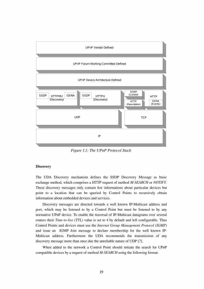
Figure 1.1 (taken from [2]) shows the UPnP Protocol Stack that is used for UPnP networking. Providing a high degree of freedom the highest layer shall only consist of vendorspecific information about the particular UPnP Control Point or UPnP Device.
Even services might be extended by vendorspecific actions and state variables. Descending the stack, this vendorspecific information is complemented by information defined by the UPnP Forum, namely the definitions made in UPnP Device and UPnP Service Templates.
The UDA itself provides and references the XML templates, which enclose the information from the layers above. Different message types for the above mentioned steps in UPnP networking are then hosted in UPnPspecific protocols, which are consistently based upon HTTP [3].
That is the discovery step uses the Simple Service Discovery Protocol (SSDP). SSDP defines search requests which are sent by Control Points to a fixed IPMulticast address upon booting up. A UPnP Device will use SSDP presence announcements to advertise itself and its embedded services to any Control Point on the network.
The control step employs the Simple Object Access Protocol (SOAP) [4] to describe remote procedure calls (RPC) from a Control Point to a service, in terms of UPnP action requests. An action request will contain the type of action along with an appropriate set of parameters. The response to such action request is again a SOAP message containing return parameters defined by the specific UPnP Service Template.
As the name implies UDA defines the Generic Event Notification Architecture (GENA) to model the UDA's eventing capabilities. Hence, GENA specifies the concepts of subscribers and publishers of notifications to enable events. Control Points in that sense will act as subscribers for any evented state variable, while the respective service will publish changes to that state variable to the subscriber. A subscription can also be canceled using GENA. UPnP networking also uses GENA in conjunction with SSDP to generate the device's presence announcements upon joining the network.
Addressing
The UDA is based on IP addressing. Thus UDA makes the implementation of a DHCP [5] client a requirement for each Control Point and device. The implementation of a DHCP server is left optional. As a fallback mechanism Control Points and devices must follow the AutoIP [6] model in case of an unmanaged network. Nevertheless, the UDA assumes networks only to be currently unmanaged. Therefore a periodic check for DHCP servers must be performed if the current IP address was determined using AutoIP.
18
Discovery
The UDA Discovery mechanism defines the SSDP Discovery Message as basic exchange method, which comprises a HTTP request of method MSEARCH or NOTIFY. These discovery messages only contain few informations about particular devices but point to a location that can be queried by Control Points to recursively obtain information about embedded devices and services.
Discovery messages are directed towards a well known IPMulticast address and port, which may be listened to by a Control Point but must be listened to by any normative UPnP device. To enable the traversal of IPMulticast datagrams over several routers their Timetolive (TTL) value is set to 4 by default and left configurable. Thus Control Points and devices must use the Internet Group Management Protocol (IGMP) and issue an IGMP Join message to declare membership for the well known IPMulticast address. Furthermore the UDA recommends the transmission of any discovery message more than once due the unreliable nature of UDP [7].
When added to the network a Control Point should initiate the search for UPnP compatible devices by a request of method MSEARCH using the following format.
19
Figure 1.1: The UPnP Protocol Stack
UPnP Vendor Defined
UPnP Forum Working Committee Defined
UPnP Device Architecture Defined
HTTPMU(Discovery)
HTTPU(Discovery)
SOAP(Control)
HTTP(Description)
UDP TCP
SSDP GENA SSDP
IP
HTTP
GENA(Events)
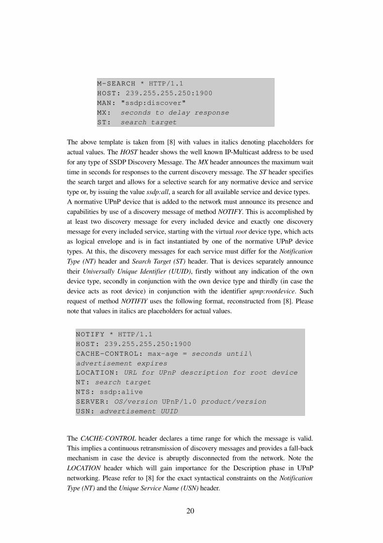
The above template is taken from [8] with values in italics denoting placeholders for actual values. The HOST header shows the well known IPMulticast address to be used for any type of SSDP Discovery Message. The MX header announces the maximum wait time in seconds for responses to the current discovery message. The ST header specifies the search target and allows for a selective search for any normative device and service type or, by issuing the value ssdp:all, a search for all available service and device types.A normative UPnP device that is added to the network must announce its presence and capabilities by use of a discovery message of method NOTIFY. This is accomplished by at least two discovery message for every included device and exactly one discovery message for every included service, starting with the virtual root device type, which acts as logical envelope and is in fact instantiated by one of the normative UPnP device types. At this, the discovery messages for each service must differ for the Notification Type (NT) header and Search Target (ST) header. That is devices separately announce their Universally Unique Identifier (UUID), firstly without any indication of the own device type, secondly in conjunction with the own device type and thirdly (in case the device acts as root device) in conjunction with the identifier upnp:rootdevice. Such request of method NOTIFIY uses the following format, reconstructed from [8]. Please note that values in italics are placeholders for actual values.
The CACHECONTROL header declares a time range for which the message is valid. This implies a continuous retransmission of discovery messages and provides a fallback mechanism in case the device is abruptly disconnected from the network. Note the LOCATION header which will gain importance for the Description phase in UPnP networking. Please refer to [8] for the exact syntactical constraints on the Notification Type (NT) and the Unique Service Name (USN) header.
20
NOTIFY * HTTP/1.1 HOST: 239.255.255.250:1900 CACHECONTROL: maxage = seconds until\ advertisement expires LOCATION: URL for UPnP description for root device NT: search target NTS: ssdp:alive SERVER: OS/version UPnP/1.0 product/version USN: advertisement UUID
MSEARCH * HTTP/1.1 HOST: 239.255.255.250:1900 MAN: "ssdp:discover" MX: seconds to delay response ST: search target
In contrast to the above mentioned abrupt disconnection from the network, the UDA defines a standard teardown phase for devices. Regarding Discovery, this teardown phase requires each device to revoke each previously issued discovery messages. This is also accomplished through the use of discovery messages of method NOTIFY including the value ssdp:byebye for the Notification Sub Type (NTS) header and omitting the headers CACHECONTROL, LOCATION and SERVER.
Description
In order to prepare the upcoming steps in UPnP networking a Control Point is interested in obtaining a device's capabilities represented by its services and in particular each service's actions and state variables. The entry point for this information is obtained in the previous Discovery step through the LOCATION header within a discovery message. The LOCATION header points to the device description, which itself must point to embedded devices' descriptions and embedded services' descriptions. Both device and service descriptions are written in XML syntax and shall be retrieved by an HTTPGET request issued by the Control Point.
Besides the information about embedded devices and services, a device description must contain a predefined set of vendorspecific information like device name, device number, URL to vendor's homepage et cetera. The information about embedded services within a device description includes the service type, service name, a URL for a separate, more detailed service description, a URL for control messages and a URL for eventing.
A UPnP service description defines actions and their arguments to be issued by the Control Point. Furthermore, the service description contains state variables, their data types and values ranges, and their characteristics towards events. The service description also indicates action arguments as input or output arguments and relates them with a state variable. A service must at least maintain one state variable.
Both device and service description follow standard templates as defined by the UPnP Forum. Since both description types are written by vendors, standard templates define placeholders for vendorspecific information about device and service properties. Hence, device and service descriptions instantiate these normative templates, which are derived from either the UPnP Template Language for devices or services. In this sense the expression Template Language denotes an appropriate XML Schema that in turn is instantiated by the various templates.
Control
By retrieving the service descriptions of a supported UPnP Device, a Control Point becomes aware of the device's capabilities. UDA defines the means to exploit these capabilities, which are represented by certain actions. These actions are typically designed for two particular needs of Control Points. That is either the userdriven change
21
the runtime state of a service or the request for an actual value of a state variable. Therefore each service maintains a state table that consists of all state variables and that is altered either altered upon internal conditions or the invocation of actions in conjunction with one or more input variables.
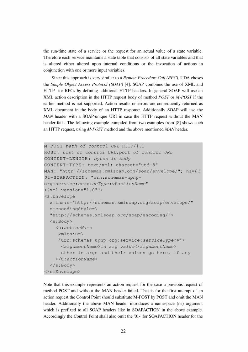
Since this approach is very similar to a Remote Procedure Call (RPC), UDA choses the Simple Object Access Protocol (SOAP) [4]. SOAP combines the use of XML and HTTP for RPCs by defining additional HTTP headers. In general SOAP will use an XML action description in the HTTP request body of method POST or MPOST if the earlier method is not supported. Action results or errors are consequently returned as XML document in the body of an HTTP response. Additionally SOAP will use the MAN header with a SOAPunique URI in case the HTTP request without the MAN header fails. The following example compiled from two examples from [8] shows such an HTTP request, using MPOST method and the above mentioned MAN header.
Note that this example represents an action request for the case a previous request of method POST and without the MAN header failed. That is for the first attempt of an action request the Control Point should substitute MPOST by POST and omit the MAN header. Additionally the above MAN header introduces a namespace (ns) argument which is prefixed to all SOAP headers like in SOAPACTION in the above example. Accordingly the Control Point shall also omit the '01' for SOAPACTION header for the
22
MPOST path of control URL HTTP/1.1 HOST: host of control URL:port of control URL CONTENTLENGTH: bytes in body CONTENTTYPE: text/xml; charset="utf8"MAN: "http://schemas.xmlsoap.org/soap/envelope/"; ns=01 01SOAPACTION: "urn:schemasupnporg:service:serviceType:v#actionName" <?xml version="1.0"?> <s:Envelope xmlns:s="http://schemas.xmlsoap.org/soap/envelope/" s:encodingStyle=\ "http://schemas.xmlsoap.org/soap/encoding/"> <s:Body> <u:actionName xmlns:u=\ "urn:schemasupnporg:service:serviceType:v"> <argumentName>in arg value</argumentName> other in args and their values go here, if any </u:actionName> </s:Body> </s:Envelope>
first attempt. Like in the preceding examples, also in this SOAP example values in italics are placeholders for actual values.
Eventing
Eventing for UPnP networking denotes the announcement of state variable values due to a recent value change from one service (publisher) to one or more Control Points (subscriber). This model requires the service to maintain both a state table and a table of subscribers. Additionally the service must implement the means to allow a Control Point to subscribe and unsubscribe to its so called evented state variables. UDA accomplishes this task by defining a protocol for subscription, renewal, cancellation and event messages. Also UDA provides the eventing URL and appropriate markup to identify evented state variables within a service description.
UDA requires a service that implements eventing to maintain a list of subscribed Control Points. Per Control Point, the service shall store the following data for the time of subscription.
● Unique subscription identifier: Shall be generated by the service in response to a subscription message.
● Delivery URL for event messages: Provided by Control Point as part of the subscription message.
● Event key: For subsequent numbering of event messages. Shall be incremented by one for each new event message to help the Control Point in detecting a message loss.
● Subscription duration: Amount of time until the subscription expires, May be updated by a renewal message. May be infinitely long. If finite, it cares for an abrupt disconnection of a Control Point.
Occupying a service's eventing system will cause the Control Point to receive all event messages (all evented state variables). The model does not support the subscription for a particular event message.
UDA defines a subscription message to be an HTTP request of method SUBSCRIBE using the headers CALLBACK, NT and TIMEOUT. The CALLBACK header provides the above introduced delivery URL for event messages. The NT header is fixed to the value 'upnp:event' whereas the TIMEOUT header provides the subscription duration. The response to a subscription message includes the unique subscription identifier in the SID header that has to be included in subsequent renewal and cancellation messages from the Control Point, as well as in the pending event
23
messages. A subscription message also triggers an initial event message (event key is 0) which will be sent to the Control Point regardless of any interim cancellation message.
Similar to the subscription message, a renewal message is defined as HTTP request of method SUBSCRIBE including the SID and TIMEOUT header. Accordingly an unsubscribe message is given as HTTP request of method UNSUBSCRIBE including only the SID header, which includes the unique subscription identifier for the subscription that is requested to being canceled.
The event message itself is defined as HTTP request of type NOTIFY, which includes various headers. The SID header again provides the unique subscription identifier, NT is fixed to upnp:event, NTS is fixed to upnp:propchange and SEQ is carrying the event key. Having its length in bytes determined by the CONTENTLENGTH header, the body of the HTTP request consists of an XML document of type propertyset, listing all evented state variables and their current value.
Presentation
A UPnP device may include a presentation URL within its device description. This presentation URL shall offer a web page whose capabilities are solely vendorspecific. UDA defines only one restrictions for the implementation, namely the usage of HTML 3.0 or later. A Control Point may issue an HTTP GET request to the presentation URL and display the content via some web browser. UDA states the control of a device and/or the representation of the device status as possible capabilities of the web page.
1.3 UPnP AV Architecture
Although stressing the independence of the content that is likely to be discovered through the use of UPnP, the UPnP Forum declares Digital Entertainment as one of the major UPnP scenarios. The explicit platform independence and usage of open internetbased communication standards like IP, TCP, HTTP and XML makes UPnP a considerable candidate for the distribution of AV content over home networks.
Hence the UPnP Forum specifies the framework for the application of UPnP technology to the distribution of AV content as UPnP AV Architecture in [9]. Within this AV application range UPnP defines in [10] and [11] the two passive nodes UPnP AV MediaRenderer and AV MediaServer.
The UPnP AV Architecture introduces the usage of UPnP for AV scenarios by means of three distinct components that perform welldefined roles. These three logical components are introduced as UPnP AV Control Point, UPnP AV MediaRenderer and UPnP AV MediaServer. In the following text, we will omit the prefix 'UPnP AV' if addressing one of the three components.
24
[9] gives an informative overview of the UPnP AV Architecture by explaining the toplevel steps of interaction between Control Point, MediaRenderer and MediaServer. [9] states the goals for interoperability between UPnP Devices as the support of arbitrary data formats and transfer protocols as well as the content transmission between source and sink without interaction of a Control Point. Since the UPnP AV Architecture neither specifies nor recommends data formats and transfer protocols an explicit nongoal is the synchronized playback to multiple rendering devices.
The UPnP AV Architecture includes both a Playback and Recording Architecture. This research project only deals with the Playback Architecture. Please refer to [9] for further information about the Recording Architecture.
1.3.1 Playback Architecture
The most common example of use for AV content in classical systems is the transmission from an arbitrary source for AV content (for example DVD Player, DVB PCICard) to an appropriate rendering device (for example TV, Software Media Player). The UPnP AV Playback Architecture maps this typical scenario to the UPnP domain. In the UPnP AV model the MediaServer contains or has access to arbitrary types of AV data and is able to distribute this data using an arbitrary transfer protocol. The MediaRenderer is capable of rendering at least one type of AV data offered by the MediaServer, using one of the available transfer protocols.
User interaction with both MediaRenderer and MediaServer is achieved through the use of a Control Point. All three components follow the UDA (see section 1.2) and are extended according to their field of operation. Hence, a Control Point shall allow the user to discover AV content from any available MediaServer. Unlike in nonAV scenarios where devices are typically not intended to interact, in AV scenarios the Control Point shall also initiate an outofband connection between source and sink in order to render some previously chosen piece of AV content.
The Playback architecture does not restrict the physical combination of any of the three logical AV devices. That is a UPnP aware TV set may and most probably will incorporate a MediaRenderer as well as a Control Point. Such an arbitrary combination is referred to as Combo Device.
Although the Playback Architecture must assume one common set of transmission protocol and data format for MediaRenderer and MediaServer, this assumption might be critical in practice. In fact this simple constraint might not be met due to today's large variety of content formats and transmission protocols, especially if identifiers are ambiguous like for example MPEG2.
25
1.3.2 Control Point within AV scenario
Although the abstract model of the Control Point is the source for any user interaction with UPnP AV Devices the layout of the Control Point's User Interface (UI) and the functionality it provides is solely left to the Control Point's manufacturer. Hence the UPnP Forum does not address the Control Point as entity in a single document, but defines its functionality in contrast to the single services a UPnP AV Device shall include according to the respective UPnP Device Template. The current thesis adopts this way of introducing details about the Control Point's functionality. However, the following listing shall expose a toplevel view on the Control Point's theory of operation with respect to chronology.
● Discovery of UPnP AV Devices: Control Points discover MediaRenderer and MediaServer devices on a home network using the steps of UPnP networking as introduced in section 1.2.
● Retrieving available AV content: Control Points invoke either Browse() or Search() actions to retrieve available AV content. These actions address the MediaServer's ContentDirectory Service (CDS) [12]. CDS processes the action requests and returns XML metadata to describe the offered content. Especially transmission protocols and data formats related to each piece of AV content is included in the metadata description.
● Obtain MediaRenderer's capabilities: In order to determine which content format and transmission protocol should be used to transfer content from the MediaServer to the MediaRenderer, the Control Point invokes the GetProtocolInfo() action. This action is addressed to the MediaRenderer's ConnectionManager Service (CMS)[13].
● Compare and match protocol and format: The information about MediaServer's and MediaRenderer's capabilities to offer and render AV content is compared to find a common set. This layout offers the possibility to leave the Control Point independent and even unaware of any type of data format or transmission protocol, since a simple string matching provides this functionality.
● Configure Server and Renderer: The configuration of both MediaServer and MediaRenderer implies the presence of optional services and respective service actions. If implemented for at least one AV Device, the Control Point invokes the PrepareForConnection() action that addresses the CMS. This action request includes the previously
26
determined common set of capabilities, containing the transmission protocol and data format. If the particular AV Device implements the AVTransport Service (AVTS) [14], CMS may chose to return an AVTransportID that identifies a newly created AVTS instance. The Control Point shall use the AVTransportID to control the pending data flow (for example Play, Pause, Seek action requests). The decision when to implement the AVTS depends on the used transmission protocol. That is push protocol sessions are typically controlled by the source (for example RTP based transmission) whereas pull protocol sessions are usually controlled by the data sink (for example HTTP GET). A further optional service for the MediaRenderer is the RenderingControl Service (RCS) [15]. CMS may also return a RCS InstanceID, which allows a Control Point to adjust certain rendering properties of one particular instance of RCS (for example SetVolume, SetBrightness actions).Considering more than one Control Point in the home network, UPnP takes no precautions itself to avoid the improper use of the above instance identifiers. That is [13] section 2.5.5.6 explicitly leaves the coordination of action requests to CMS and RCS to the Control Points. Obviously this settlement may be very critical in practice since the interaction between Control Points is neither covered by the UPnP AV Architecture nor by UDA.If for some reasons there is no AVTransportID available to the CP, it shall use the value 0 as InstanceID value to control the flow of content (assuming AVTS implemented).
● Selection of AV content: This step either relies on the optional AVTS or a private vendor implementation. If AVTS is implemented and the CP is aware of the respective InstanceID, the CP will invoke the SetAVTransportURI() action on the AVTS in order to identify the particular content item to be transferred. Since the AV Device Templates leave a high degree of freedom for vendor extensions especially for Combo Devices, it is highly possible and explicitly permitted (see [9] chapter 5) that the individual components communicate using some private communication mechanism. That is for example a Control Point which is physically combined with a MediaRenderer (for example a Multimedia settop box) may provide an RTSP [16] or HTTP [3] module directly with the AV content location instead of making a detour over the AVTS. Due to the fact that most protocol sessions are initiated and maintained by the sink device, the MediaServer will likely not need to implement the PrepareForConnection() action and therefore the AVTS may be dispensable as well.
27
● Initiation of content transfer: Like the last step, the initiation of content transfer either relies on the AVTS or a private vendor mechanism. Also due to the probable lack of the AVTS for the MediaServer, this step focuses on the MediaRenderer. If implemented, the CP will invoke control actions like Play(), Pause() and Seek() on the MediaRenderer's AVTS. These actions will obviously be translated to an appropriate equivalent within the chosen transfer protocol's domain. If again a Combo Device is considered, the Control Point may incorporate the translating facility and therefore access the respective protocol module directly.
● Adjustment of rendering properties: If a device implements the RenderingControl Service action requests might be sent to alter various rendering properties. Therefore [15] almost only consists of state variable and related action descriptions to allow adjustment for properties like brightness, contrast, sharpness, color temperature and of course volume.
● Cleanup MediaRenderer/MediaServer: A Control Point may, but is not required to request the ConnectionComplete() action from the sink and source CMS. In case of an abort or the end of a transmission the Control Point may inform the involved devices about the deallocation of resources and the release of virtual instances of AVTS and RCS. Additionally each device shall also provide an automatic cleanup mechanism, since the ConnectionComplete() action is also optional.
1.3.3 UPnP AV MediaRenderer
As intended sink for AV data in UPnP networking, the UPnP Forum defines the generalpurpose UPnP AV MediaRenderer Device Template. Due to today's large variety of Consumer Electronics (CE), the MediaRenderer Template incorporates many presumable rendering features of possibles MediaRenderer instances. The MediaRenderer template is designed to achieve the following goals.
● Exposition of supported transmission protocols and data formats.
● Control of rendering characteristics of the underlying hardware.
● Control of the content flow depending on the chosen transmission protocol
The above functionalities are provided through the use of designated services and the invocation of respective actions to such service. To serve these particular AV
28
requirements of a data sink the UPnP Forum defines appropriate Service Templates and makes service instances either mandatory or optional elements of a MediaRenderer. That is a MediaRenderer typically consists of exactly one instance of the ConnectionManager Service (CMS) [13] and exactly one instance of the RenderingControl Service (RCS) [15] and AVTransport Service (AVTS) [14]. In this context CMS and RCS are required components, whereas AVTS is an optional feature.
CMS has a key role for the control of a MediaRenderer. In addition to the exposition of supported transmission protocols and data formats, CMS performs several other tasks explained hereafter. Thinking of the Description step in UPnP networking (see section 1.2) one could assume the supported protocols and data formats to be part of the device description. In fact this is not the case. The CMS Template models this information by means of the state variable SinkProtocolInfo which partially models the overall state of a MediaRenderer. As the name implies, the value of such state variables may change over time, which for example accounts for temporarily exceeded network resources. The SinkProtocolInfo state variable provides a link between supported protocols and data formats through a Comma Separated Value (CSV) list of strings that are formatted as follows.
By invoking the mandatory GetProtocolInfo() action on a MediaRenderer's CMS a Control Point requests the current value of the SinkProtocolInfo state variable in order to perform capability matching between MediaRenderer and MediaServer.
Assuming a MediaRenderer's capability to render multiple pieces of AV content simultaneously (for example picture in picture playback) implementing the CMS PrepareForConnection() action is required by the UPnP AV MediaRenderer Device Template. By providing the desired protocol as input argument for PrepareForConnection(), the Control Point specifies the type of connection to bet set up prior to the actual transmission. The PrepareForConnection() action then cares for the allocation of further connection resources (for example TCP sockets) and the creation of new virtual RCS and AVTS instances. The overall set of persistent connections is maintained by CMS in terms of a list containing unique ConnectionID identifiers. New virtual RCS and AVTS instances are uniquely identified through such ConnectionID value in conjunction with a unique InstanceID value that is also generated by CMS in response to a PrepareForConnection() request. Hence, the meaning of the term virtual instance in this context can be described as a set of state variables that apply only to one particular connection (i.e. one particular content transfer), uniquely identified by ConnectionID and InstanceID value. Further action requests directed towards these new virtual instances must consequently contain these InstanceID values in order to distinguish between different rendering and transport resources.
29
<protocol>“:”<network>“:”<contentFormat>“:”<additionalInfo>
Note that the support for the simultaneous playback of multiple AV content is optional and consequently neither the implementation of the PrepareForConnection() action nor the support for multiple RCS and AVTS instances is required.As a reminder, the implementation of actions is announced via the service description. If a vendor choses not to implement PrepareForConnection for a MediaRenderer's CMS the model of InstanceID identifiers still holds. In that case the Control Point shall use InstanceID 0 to address the one and only RCS and/or AVTS instance.
As mandatory component of a MediaRenderer, the RenderingControl Service offers the functionality to query and control the rendering characteristics of the underlying hardware. Regarding the Description phase in UPnP networking, a Control Point retrieves the RCS service description that includes the set of characteristics that are configurable and the set of actions to query and change these state variables. Thinking of a UPnP capable TV set, RCS defines state variables for characteristics like brightness, contrast, sharpness, color intensity and volume, which can be queried or altered by similarly named Get and Setactions.
Subject to the supported transmission protocol the MediaRenderer instance shall include the AVTransport Service (AVTS). If a MediaRenderer supports pull protocols like HTTP and accordingly is the active (pulling) part in the the flow of AV content, it is responsible for providing the AVTS. Having located a desired piece of AV content, a Control Point initiates the transmission by requesting the SetAVTransportURI() action from the MediaRenderer's AVTS. While operating, the main purpose of AVTS is the control of the TransportState state variable, which forms the core of AVTS by defining the toplevel state of an AVTS instance. The AVTS Template models this functionality in terms of a state machine. The transitions between the different TransportState values are achieved by several AVTransport actions like for example Play(), Pause() and Seek(). Accordingly AVTS defines possible values for the TransportState variable as PLAYING, STOPPED, PAUSED_PLAYBACK et cetera. In addition to the rendering capabilities of a MediaRenderer, AVTS also cares for possible recording capabilities of a MediaRenderer like a builtin DVD recorder or HDD. In such case a vendor may chose to implement these recordtostoragemedium and playbackfromstoragemedium capabilities without setting up a UPnP AV MediaServer device for that purpose. AVTS offers optional state variables and actions to meet such requirements. Though it must be noted that AVTS does not cover scheduled recording, which surely reduces the application of AVTS's recording abilities to instantaneous user interaction for example the download of a music track from the internet.
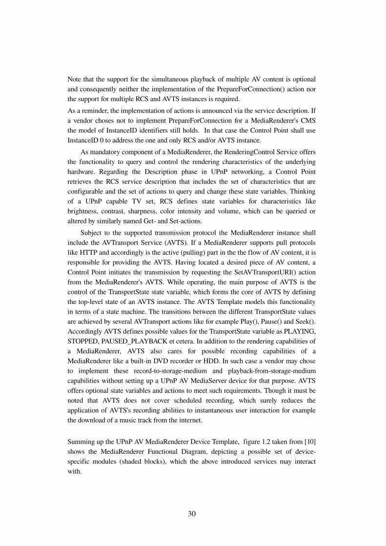
Summing up the UPnP AV MediaRenderer Device Template, figure 1.2 taken from [10] shows the MediaRenderer Functional Diagram, depicting a possible set of devicespecific modules (shaded blocks), which the above introduced services may interact with.
30
Thinking of specialpurpose rendering devices with extensive requirements towards control of certain characteristics, the above functional diagram might be extended by means of additional devicespecific modules, services and service actions, defined by the vendor. The UPnP AV MediaRenderer Device Template requires information about such additional capabilities to be ignored by normative devices as long as they do not violate the naming conventions and XML rules specified in [8] section 2.5. Although, assuming a Control Point/MediaRenderer Combo Device (see [9] chapter 5), which internally interacts not following the UPnP system architecture, the above functional diagram may even lack all three AV services. That is a Control Point may access directly the available vendorspecific, possibly more sophisticated interfaces. Such implementation would surely prevent the rendering hardware from being used by another Control Point but nevertheless might by acceptable for the sake of reusability of existing vendorspecific interfaces. This consideration might well be applicable for rendering devices that overcome the control abilities of the normative part of the UPnP AV MediaRenderer Device Template.
1.3.4 UPnP AV MediaServer
As intended source for AV data in UPnP networking, the UPnP Forum defines the generalpurpose UPnP AV MediaServer Device Template. Considering today's diversity of AV data types, the UPnP AV MediaServer Template provides the means to describe and share AV content using the UPnP AV Architecture. The UPnP AV MediaServer Template claims itself to be very leightweight. This was recently approved by its application to cell phones, where a UPnP AV MediaServer enables the discovery of AV content from such cell phone (for example pictures or voice recordings) by some more adequate rendering device. The AV MediaServer Device Template is designed to achieve the following goals.
31
Figure 1.2: MediaRenderer Functional Diagram
● Enumeration and query of any of the content that the MediaServer can provide to the home network, even nonAV content.
● Provisioning of Control Points with a list of supported data formats and transmission protocols to enable capability matching between MediaRenderer and MediaServer.
● Control the flow of content (for example Play, Pause, Seek) in case of supported pull protocols for which the MediaServer is the active (pushing) part of the transmission.
● Retrieval (instantaneous recording) of content from another device or external resource in order to transmit this content for example at a later point in time.
● Recording content using the ScheduledRecording Service
The UPnP AV MediaServer Device Template defines different services to be part of a MediaRenderer instance, in order to achieve the above goals. Similar to the MediaRenderer requirements, a MediaServer must contain exactly one ConnectionManager Service instance. Additionally a MediaServer must implement exactly one ContentDirectory Service instance, which itself covers the numerous requirements towards the description of all possible types of data a MediaServer may provide. Again, dependent on the types of supported transmission protocols a MediaServer may have to implement exactly one instance of the AVTransport Service. If a vendor choses to equip the MediaServer with recording capabilities, the MediaServer shall also implement exactly one instance of the ScheduledRecording Service.
The usage of CMS for the MediaServer follows the concept introduced for the MediaRenderer. That is supported content formats and transmission protocols can be retrieved by a Control Point as response to request for the mandatory GetProtocolInfo() action. Nevertheless, the MediaRenderer offers further means to discover this information using the CDS. As a reminder, a MediaRenderer must implement the PrepareForConnection() as part of CMS, as soon as it supports multiple simultaneous playback of AV content. The requirements for the implementation of the PrepareForConnection() action within a MediaServer are slightly more complex. That is not only the support for multiple simultaneous transmissions requires PrepareForConnection(), but also the type of the applied transmission protocol influences the requirement for PrepareForConnection() as part of the MediaServer's CMS. In other words, if a MediaServer supports multiple simultaneous transmission using a push protocol requires the MediaServer to implement PrepareForConnection(). In that sense PrepareForConnection() again cares for allocation of connection resources by creating virtual instances of the AVTransport Service and for example creating a UDP socket.
32
AVTS for a MediaServer is generally optional. Its implementation is only required if the MediaServer supports the transmission of at least one data format using a push protocol. That is if the MediaServer is the active (pushing) part of the transmission like for example in a RTP transmission using UDP. Hence, if AVTS is implemented a Control Point directs control messages to AVTS using either the AVTS InstanceID value returned via PrepareForConnection() or InstanceID value 0 in case PrepareForConnection() is not implemented. For the MediaServer the same control actions apply as for the MediaRenderer. That is a Control Point may initiate a transmission by invoking the SetAVTranportURI() action and subsequently control the transmission through for example Play(), Pause() and Seek() action requests.
As introduced in the MediaRenderer description above, AVTS provides the ability to record content. Unfortunately the scheduling of a recording is not within the scope of AVTS. The definition of the ScheduledRecording Service (SRS) Template [17] overcomes this limitation by enabling Personal Video Recorder (PVR) like applications. SRS mainly focuses on Broadcast content but may also be applied to any file based content. Therefore SRS provides the means to describe many possible instructions to specify a userlevel recording. Mainly SRS relies on content information available through the MediaServer's CDS. What is more, SRS is able to rely on Electronic Program Guide (EPG) information, provided either by the MediaServer's CDS or some external database. The vendorspecific implementation of SRS and CDS may also include the integration of previously recorded content into the CDS. Recording of particular content is managed through the abstract recordSchedule model which includes userlevel instructions to identify the desired piece of content. SRS enables a Control Point to create such recordSchedule instances with respect to metadata provided by the MediaServers's CDS. Additionally SRS provides actions to browse, delete and change recordSchedule instances. Discrete recording operations of such recordSchedule instances are referred to as recordTask and created on behalf of a particular recordSchedule. For example if the desired piece of AV content is currently aired, which must be verified through the MediaRenderer's CDS, SRS creates a recordTask by allocating the appropriate resources (for example filesystem entries and CDS objects). SRS also allows Control Points to browse and abort recordTask objects. As SRS is designed to exploit the already large functionality of CDS while considering various EPG related properties, SRS currently represents the most voluminous UPnP AV Service Template. Since direct and scheduled recording is not within the scope of the present work, please refer to [14] and [17] for further theory of operation and the respective action and state variable definitions.
The very important tasks enumeration and query of any content the MediaServer can provide are performed by the MediaServer's ContentDirectory Service (CDS). Since one major topic of the present thesis is the integration of DVB Service Information (DVBSI) into CDS, i will discuss the CDS features in detail within the immediately following clause.
33
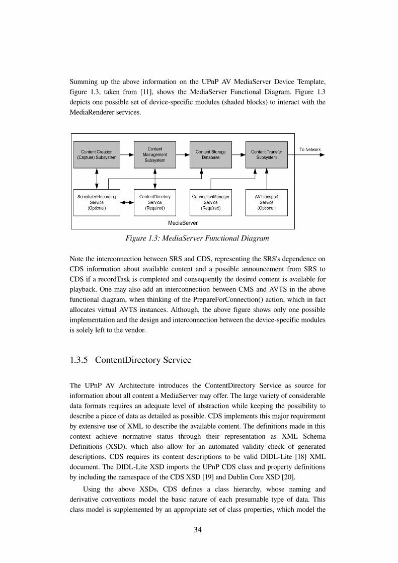
Summing up the above information on the UPnP AV MediaServer Device Template, figure 1.3, taken from [11], shows the MediaServer Functional Diagram. Figure 1.3 depicts one possible set of devicespecific modules (shaded blocks) to interact with the MediaRenderer services.
Note the interconnection between SRS and CDS, representing the SRS's dependence on CDS information about available content and a possible announcement from SRS to CDS if a recordTask is completed and consequently the desired content is available for playback. One may also add an interconnection between CMS and AVTS in the above functional diagram, when thinking of the PrepareForConnection() action, which in fact allocates virtual AVTS instances. Although, the above figure shows only one possible implementation and the design and interconnection between the devicespecific modules is solely left to the vendor.
1.3.5 ContentDirectory Service
The UPnP AV Architecture introduces the ContentDirectory Service as source for information about all content a MediaServer may offer. The large variety of considerable data formats requires an adequate level of abstraction while keeping the possibility to describe a piece of data as detailed as possible. CDS implements this major requirement by extensive use of XML to describe the available content. The definitions made in this context achieve normative status through their representation as XML Schema Definitions (XSD), which also allow for an automated validity check of generated descriptions. CDS requires its content descriptions to be valid DIDLLite [18] XML document. The DIDLLite XSD imports the UPnP CDS class and property definitions by including the namespace of the CDS XSD [19] and Dublin Core XSD [20].
Using the above XSDs, CDS defines a class hierarchy, whose naming and derivative conventions model the basic nature of each presumable type of data. This class model is supplemented by an appropriate set of class properties, which model the
34
Figure 1.3: MediaServer Functional Diagram
detailed information about a piece of data. Except for a base property set, this supplementing information is to apply to a certain class derivative.
CDS defines the base class object, which serves as parent class for all other children and may itself not be instantiated. The direct children of the object base class are defined as object.item and object.container. Any instance or further derivative of either object.item or object.container is referred to as CDS object. As the names imply, the item class is designed to describe a single piece of data, whereas the container class refers to a logical envelope for CDS objects either derived from item or container itself.
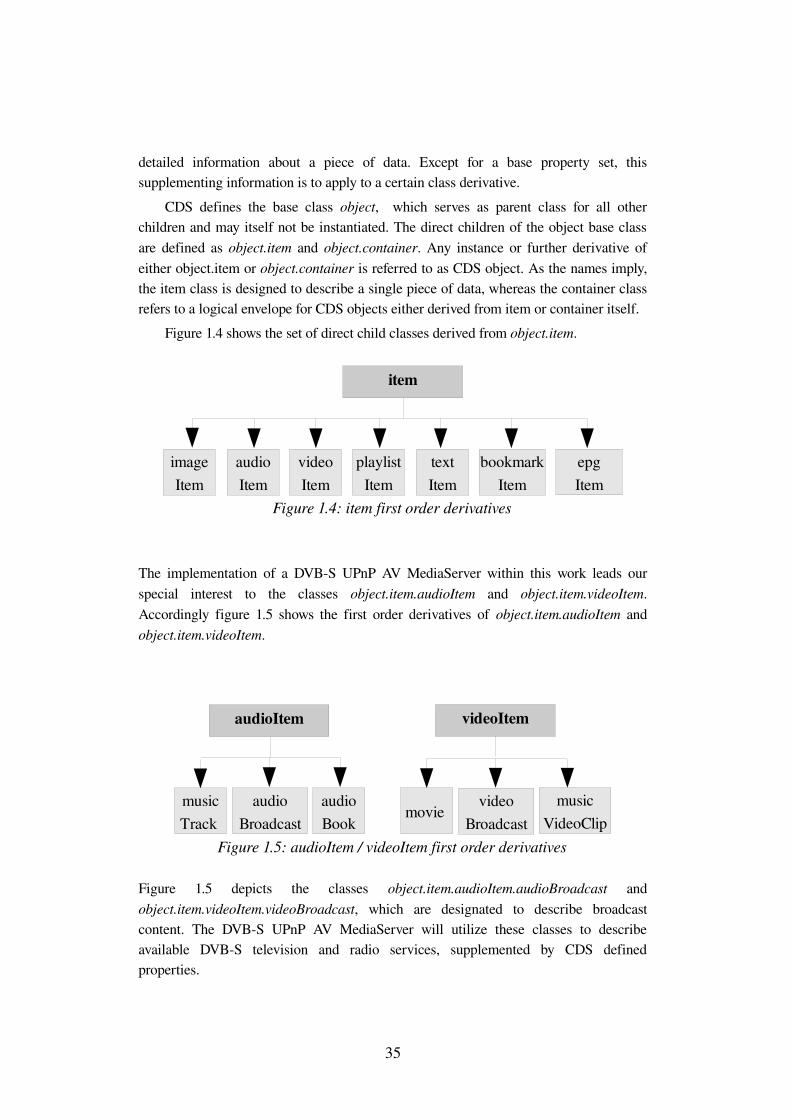
Figure 1.4 shows the set of direct child classes derived from object.item.
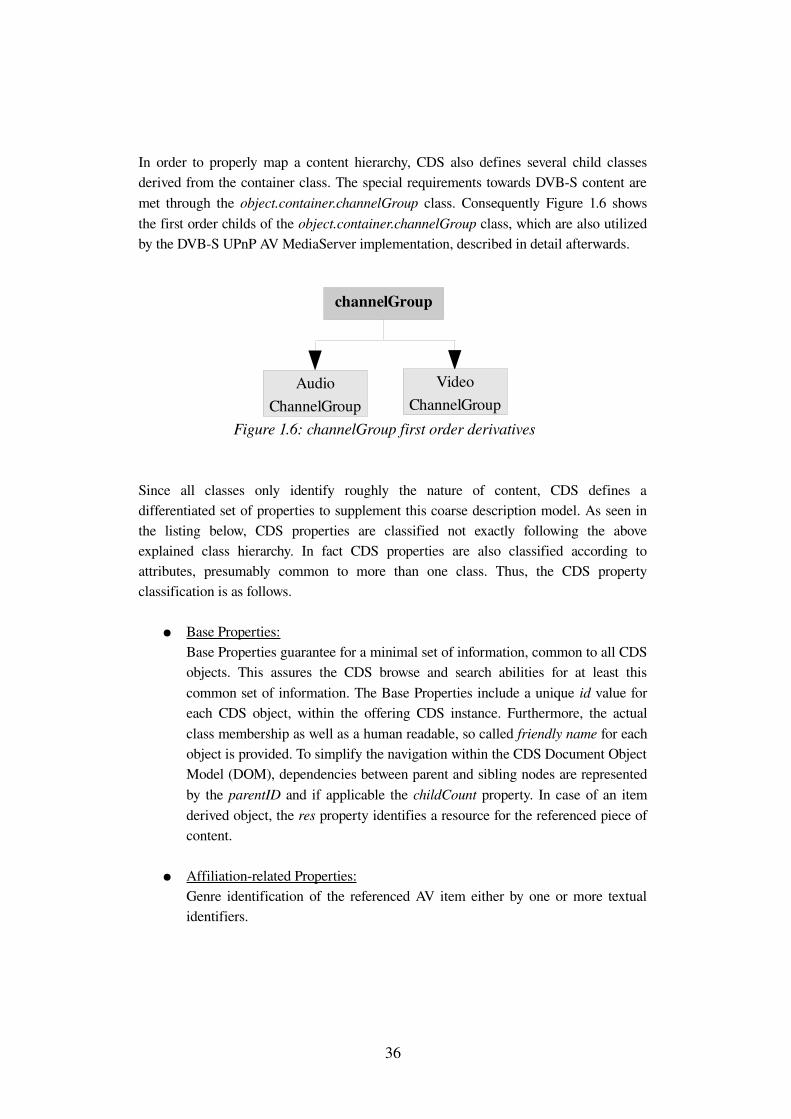
The implementation of a DVBS UPnP AV MediaServer within this work leads our special interest to the classes object.item.audioItem and object.item.videoItem. Accordingly figure 1.5 shows the first order derivatives of object.item.audioItem and object.item.videoItem.
Figure 1.5 depicts the classes object.item.audioItem.audioBroadcast and object.item.videoItem.videoBroadcast, which are designated to describe broadcast content. The DVBS UPnP AV MediaServer will utilize these classes to describe available DVBS television and radio services, supplemented by CDS defined properties.
35
Figure 1.4: item first order derivatives
epgItem
bookmark Item
text Item
playlist Item
video Item
audio Item
image Item
item
Figure 1.5: audioItem / videoItem first order derivatives
audio Book
audio Broadcast
music Track
audioItem
music VideoClip
video Broadcast
movie
videoItem
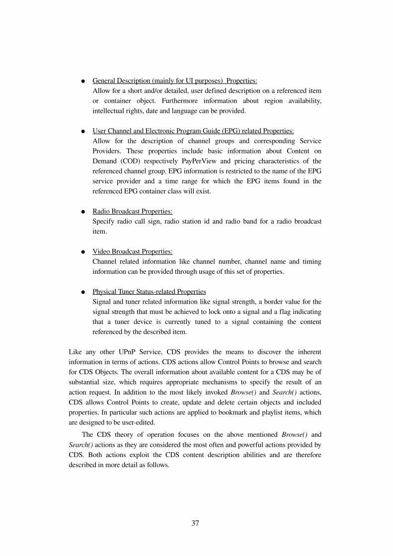
In order to properly map a content hierarchy, CDS also defines several child classes derived from the container class. The special requirements towards DVBS content are met through the object.container.channelGroup class. Consequently Figure 1.6 shows the first order childs of the object.container.channelGroup class, which are also utilized by the DVBS UPnP AV MediaServer implementation, described in detail afterwards.
Since all classes only identify roughly the nature of content, CDS defines a differentiated set of properties to supplement this coarse description model. As seen in the listing below, CDS properties are classified not exactly following the above explained class hierarchy. In fact CDS properties are also classified according to attributes, presumably common to more than one class. Thus, the CDS property classification is as follows.
● Base Properties: Base Properties guarantee for a minimal set of information, common to all CDS objects. This assures the CDS browse and search abilities for at least this common set of information. The Base Properties include a unique id value for each CDS object, within the offering CDS instance. Furthermore, the actual class membership as well as a human readable, so called friendly name for each object is provided. To simplify the navigation within the CDS Document Object Model (DOM), dependencies between parent and sibling nodes are represented by the parentID and if applicable the childCount property. In case of an item derived object, the res property identifies a resource for the referenced piece of content.
● Affiliationrelated Properties: Genre identification of the referenced AV item either by one or more textual identifiers.
36
Figure 1.6: channelGroup first order derivatives
Video ChannelGroup
channelGroup
Audio ChannelGroup
● General Description (mainly for UI purposes) Properties: Allow for a short and/or detailed, user defined description on a referenced item or container object. Furthermore information about region availability, intellectual rights, date and language can be provided.
● User Channel and Electronic Program Guide (EPG) related Properties: Allow for the description of channel groups and corresponding Service Providers. These properties include basic information about Content on Demand (COD) respectively PayPerView and pricing characteristics of the referenced channel group. EPG information is restricted to the name of the EPG service provider and a time range for which the EPG items found in the referenced EPG container class will exist.
● Radio Broadcast Properties: Specify radio call sign, radio station id and radio band for a radio broadcast item.
● Video Broadcast Properties: Channel related information like channel number, channel name and timing information can be provided through usage of this set of properties.
● Physical Tuner Statusrelated Properties Signal and tuner related information like signal strength, a border value for the signal strength that must be achieved to lock onto a signal and a flag indicating that a tuner device is currently tuned to a signal containing the content referenced by the described item.
Like any other UPnP Service, CDS provides the means to discover the inherent information in terms of actions. CDS actions allow Control Points to browse and search for CDS Objects. The overall information about available content for a CDS may be of substantial size, which requires appropriate mechanisms to specify the result of an action request. In addition to the most likely invoked Browse() and Search() actions, CDS allows Control Points to create, update and delete certain objects and included properties. In particular such actions are applied to bookmark and playlist items, which are designed to be useredited.
The CDS theory of operation focuses on the above mentioned Browse() and Search() actions as they are considered the most often and powerful actions provided by CDS. Both actions exploit the CDS content description abilities and are therefore described in more detail as follows.
37
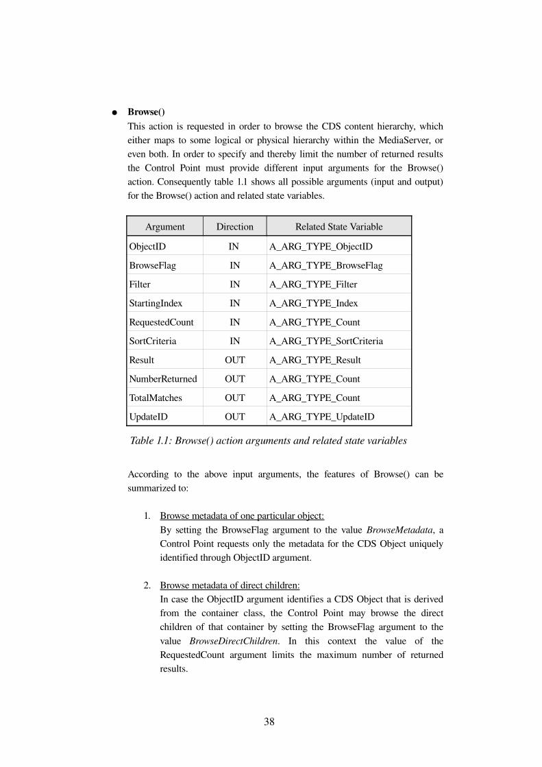
● Browse()This action is requested in order to browse the CDS content hierarchy, which either maps to some logical or physical hierarchy within the MediaServer, or even both. In order to specify and thereby limit the number of returned results the Control Point must provide different input arguments for the Browse() action. Consequently table 1.1 shows all possible arguments (input and output) for the Browse() action and related state variables.
Argument Direction Related State Variable
ObjectID IN A_ARG_TYPE_ObjectID
BrowseFlag IN A_ARG_TYPE_BrowseFlag
Filter IN A_ARG_TYPE_Filter
StartingIndex IN A_ARG_TYPE_Index
RequestedCount IN A_ARG_TYPE_Count
SortCriteria IN A_ARG_TYPE_SortCriteria
Result OUT A_ARG_TYPE_Result
NumberReturned OUT A_ARG_TYPE_Count
TotalMatches OUT A_ARG_TYPE_Count
UpdateID OUT A_ARG_TYPE_UpdateID
Table 1.1: Browse() action arguments and related state variables
According to the above input arguments, the features of Browse() can be summarized to:
1. Browse metadata of one particular object: By setting the BrowseFlag argument to the value BrowseMetadata, a Control Point requests only the metadata for the CDS Object uniquely identified through ObjectID argument.
2. Browse metadata of direct children: In case the ObjectID argument identifies a CDS Object that is derived from the container class, the Control Point may browse the direct children of that container by setting the BrowseFlag argument to the value BrowseDirectChildren. In this context the value of the RequestedCount argument limits the maximum number of returned results.
38
3. Incremental browsing: To avoid resource overflow, the Control Point may discover the CDS hierarchy in an incremental manner. That is through provisioning of the StartingIndex and RequestedCount argument, the Control Point is able to specify an initial offset for the request and again the maximum number of returned results.
4. Sorting by a supported sort order: This feature requires the preceding retrieval of CDS sort capabilities by invoking the GetSortCapabilities() action, which will return the current value of the SortCapabilities state variable. That is the SortCapabilities state variable consists of a Comma Separated Value (CSV) list of CDS properties that CDS can use to sort Search() and Browse() action requests. Such sort property can then be passed as value of the Filter argument, with a preceding '+' denoting ascending and '' a descending result order.
As response to all the above Browse() layouts, CDS will return a valid DIDLLite XML document as value for the output Result argument. Thinking of Control step in UPnP networking, the resulting XML document is encapsulated within the XML body of an appropriate SOAP message. That is the DIDLLite document has to be well escaped to not violate the environmental SOAP document. Escaping metadata as value for other metadata is described in [21] section 2.4 (Character Data and Markup). Also if the result is includes a CSV list, commas (“,”) that appear within XML must be escaped as “\,” as defined in [21] section 1.2.2 (Strings Embedded in Other Strings). The escaped result is supplemented by the NumberReturned and TotalMatches argument values, which only shall differ in case the RequestedCount value is smaller than the actual number of matching browse results.
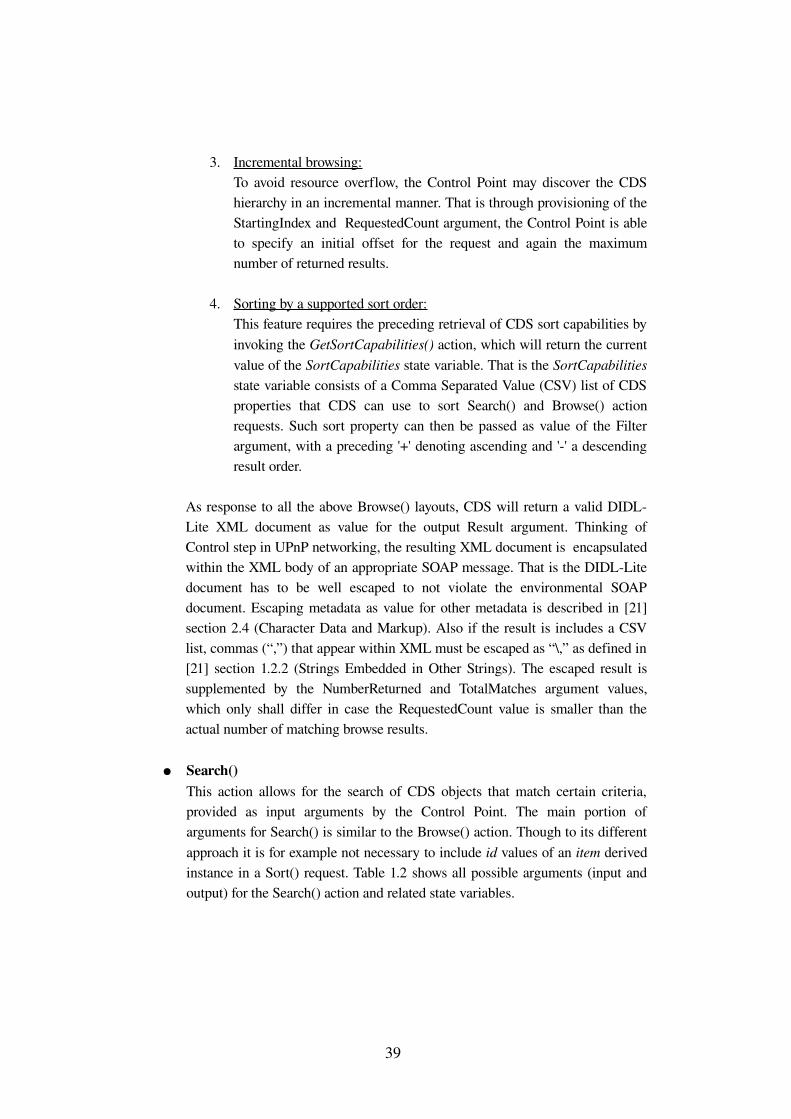
● Search()This action allows for the search of CDS objects that match certain criteria, provided as input arguments by the Control Point. The main portion of arguments for Search() is similar to the Browse() action. Though to its different approach it is for example not necessary to include id values of an item derived instance in a Sort() request. Table 1.2 shows all possible arguments (input and output) for the Search() action and related state variables.
39
Argument Direction Related State Variable
ContainerID IN A_ARG_TYPE_ObjectID
SearchCriteria IN A_ARG_TYPE_SearchCriteria
Filter IN A_ARG_TYPE_Filter
StartingIndex IN A_ARG_TYPE_Index
RequestedCount IN A_ARG_TYPE_Count
SortCriteria IN A_ARG_TYPE_SortCriteria
Result OUT A_ARG_TYPE_Result
NumberReturned OUT A_ARG_TYPE_Count
TotalMatches OUT A_ARG_TYPE_Count
UpdateID OUT A_ARG_TYPE_UpdateID
Table 1.2: Search() action arguments and related state variables
According to the above input arguments, the features of Browse can be summarized to:
1. Incremental searching: Similar to the Browse() action, a Control Point may limit the maximum number of returned results by setting the RequestedCount argument. An incremental search also includes a valid StartingIndex argument that specifies an object id value as initial offset for Search().
2. Sorting: Similar to the Browse() action, a Control Point may request a certain sort order of the results returned within the Result argument. That is achieved by providing an appropriate SortCriteria argument. Supported values for the SortCriteria argument must be retrieved in advance by invoking the GetSortCapabilities action. Syntax and semantics of the result are according to the Browse() action.
3. Filtering: The Filter argument contains a CSV list of CDS properties to be returned within single result entities of the overall DIDLLite result document. That is Filter allows for the control of complexity of the resulting metadata of a single CDS object. In that sense required properties that are not specified in the Filter argument are returned nonetheless.
40
The rules introduces with the Browse() action for escaping the DIDLLite document hold also for the Search() action.
1.3.6 Summary
The above sections gave an overview of the UPnP Architecture and its basic components, namely the UPnP Device Architecture and UPnP AV Architecture. The UPnP Device Architecture defines the application independent interaction between the two abstract device types UPnP Control Point and UPnP Device by means of six UPnP networking steps. Except for the steps Addressing (step 1) and Presentation (step 6), all other steps rely on UPnP defined and UPnP extended protocols. The UPnP Device model in that sense may be instantiated by any type of electrical device that requires some sort of interaction. As a sort of envelope, the pure UPnP Device model only implements the first three steps in UPnP networking (Addressing, Discovery and Description). All further functionality follows a modular design in terms of special purpose UPnP Services, which are integrated into a UPnP Device and perform the actual tasks that are summarized under the name of the specific UPnP Device type. According to both the UPnP Device and UPnP Service model, the UPnP Control Point model is introduces to serve two purposes, namely the automated exploration of UPnP Device capabilities (including its Services) and their userdriven application.
Having set up this toolbox of UPnP basics, the UPnP AV Architecture models the application of these basics to any type of Consumer Electronics that may deal with AV content. The UPnP AV Architecture achieves this by introducing a multipurpose UPnP source and sink Device for AV content, namely the UPnP AV MediaServer and UPnP AV MediaRenderer. The UPnP AV Architecture specifies the specialpurpose functionality of both devices through five UPnP Services, two of which are common to both MediaServer and MediaRenderer. Regarding the given research topic, the introduction of both AV Devices and the included services led to the description of the UPnP AV MediaServer and in particular its included UPnP ContentDirectory service.
41

2 DVB Home Network Reference Model
2.1 Introduction
As one of the major standard bodies for digital video broadcasting, the DVB Project2 disposes of key knowledge for the distribution of digital television services. Through the contribution of the DVBIP Phase 1 (current version 1.3.1) handbook, DVB made the first approach to standardize the delivery of DVB content over IPbased networks. The common membership of various companies in both DVB and DLNA3 consortia and the agreement about the value of both approaches led to the conclusion to integrate DVBIP into a framework compatible to DLNA. There was also unity about a basic incompatibility of DVBIP and the work done so far by DLNA. In spite of basically different Intellectual Property Rights (IPR) policies, DVB agreed to an own contribution towards Home Networking, which was apparently intended for DVBIP Phase 2.
The following section briefly introduces a top level overview of the DLNA Architecture and its Key Technology Components as one major design goal of the DVBHN Reference Model is DLNA compatibility. Additionally the DLNA Interoperability Stack uses UPnP for device discovery and control and therefore DLNA needs citation here. The further discourse in this chapter introduces DVBHN in contrast to the UPnP architecture.
2.2 Digital Living Network Alliance
The Digital Living Network Alliance (DLNA) is a crossindustry organization with more than 200 members, including consumer electronics (CE), computer industry and mobile device companies. Therefore DLNA design guidelines are intended to allow for a seamless interoperability between devices from DLNA member branches.
DLNA picks up the UPnP idea of interoperability between almost any type of device and further specifies the UPnP application to AV content by defining concrete transmission protocol and content format requirements. DLNA defines these requirements in accordance to the expected type of device (stationary or mobile) and the presumable processing capabilities for AV content.
2 Internet Presence DVB Project http://www.dvb.org3 Internet Presence DLNA http://www.dlna.org
43
DLNA Architecture
DLNA considers CE, PC and mobile devices as communicating components in a Home Network. To enable communication and control of these device classes, DLNA relies on the lightweight UPnP Architecture, which particularly meets the requirements of lowresource mobile devices. An overview of the different DLNA building blocks to achieve the intended interoperability is given below.
● Connectivity between devices in a Home Network: This assumes devices implementing a common data link layer (layer2), or in case of different layer 2 connectivity appropriate layer 2 bridging capabilities inside the Home Network, providing network layer (layer 3) routing between the different data link layers. The DLNA supported data link layers are Ethernet (according to IEEE 802.3), Wireless LAN (according to IEEE 802.11) and Bluetooth.
● Device discovery, configuration and control: As first step of the overall interoperability, all types of DLNA devices shall be able to discover the presence of each other and to determine the further use for each device in terms of available functions and content. Though if for example one device discovers its ability to render content from another device, further configuration and control might become necessary to allocate appropriate resources on both sides.
● Interoperability of content formats and transmission protocols: As soon as devices discover their general ability to exchange AV content, they must agree to a common content format and transmission protocol according to their resources. DLNA takes the precautions for interoperability on the level of content formats and transmission protocols, by defining minimum requirements for certain DLNA device categories.
● Content discovery, management and control: In order to allow all devices to discover and exchange content from another device, a common content management must be defined. This management shall provide the ability to organize, browse, search for and select the desired content.
● Compatibility of quality of service mechanisms: Considering the distribution of highdefinition content inside a Home Network, manufacturers must agree to common requirements for Quality of Service (QoS), categorizing content to be processed in prior to others. Such agreement must assure device interoperability, even in case there is no QoS implemented.
44
● Compatibility of authentication and authorization mechanisms: In order to control and grant access to particular devices and included content, common mechanisms must be provided. These mechanisms shall define single device and user authentication and authorization to enable access to for example copyprotected or agerated content.
Relation to UPnP
Thinking of the UPnP Architecture, some of the above DLNA building blocks perfectly match the different UPnP mechanisms described in chapter 1. In fact, DLNA defines the blocks Device discovery, configuration and control and Content discovery, management and control to be based upon the steps Discovery, Description and Control of UPnP Networking as defined in section 1.2 of the present document. Since the above UPnP Networking steps rely on the UPnP Device Architecture, DLNA accordingly defines specialpurpose AV source and sink device classes as well as control devices to actually allow for the application of these UPnP Networking steps. Please refer to [22] for further explanation on particular DLNA Device Classes.
DLNA overcomes a possible disadvantage of the UPnP Architecture regarding employed content formats and transmission protocols. By claiming the independence of any outofband transmission protocol, chosen to transfer any content format from a UPnP AV MediaServer to a UPnP AV MediaRenderer, the user may encounter the problem of having such devices being UPnP certified but still incompatible for implementing different streaming protocols or data types.
DLNA revises this possible issue by defining one mandatory content transmission protocol and a minimum set of required content formats to be supported by particular DLNA Device Categories. The two considered device categories are DLNA Home Devices and DLNA Mobile Devices with the set of required content formats for each category complying with their presumable processing power for AV content. The required content transfer protocol for each DLNA Device Class, belonging to either Device Category is defined to be HTTP.
Choosing HTTP as mandatory content transfer protocol may not be surprising and perhaps the only logical conclusion from the already extensive use of HTTP in almost all UPnP Networking steps.
Figure 2.1 reconstructed from [22] summarizes the observations made so far by depicting the DLNA Interoperability Guidelines Building Blocks and their concrete key technology components. Note that the listed media formats are to be seen in relation to the DLNA Device Categories and thus not all apply to every DLNA Device Class. Also note the appearance of the typically UDP based RTP as transport protocol, which in fact is native transport layer protocol for DVBIP services. Unlike in DVBIP, UDP in DLNA networking is only to be used in conjunction with the application layer protocol RTSP.
45
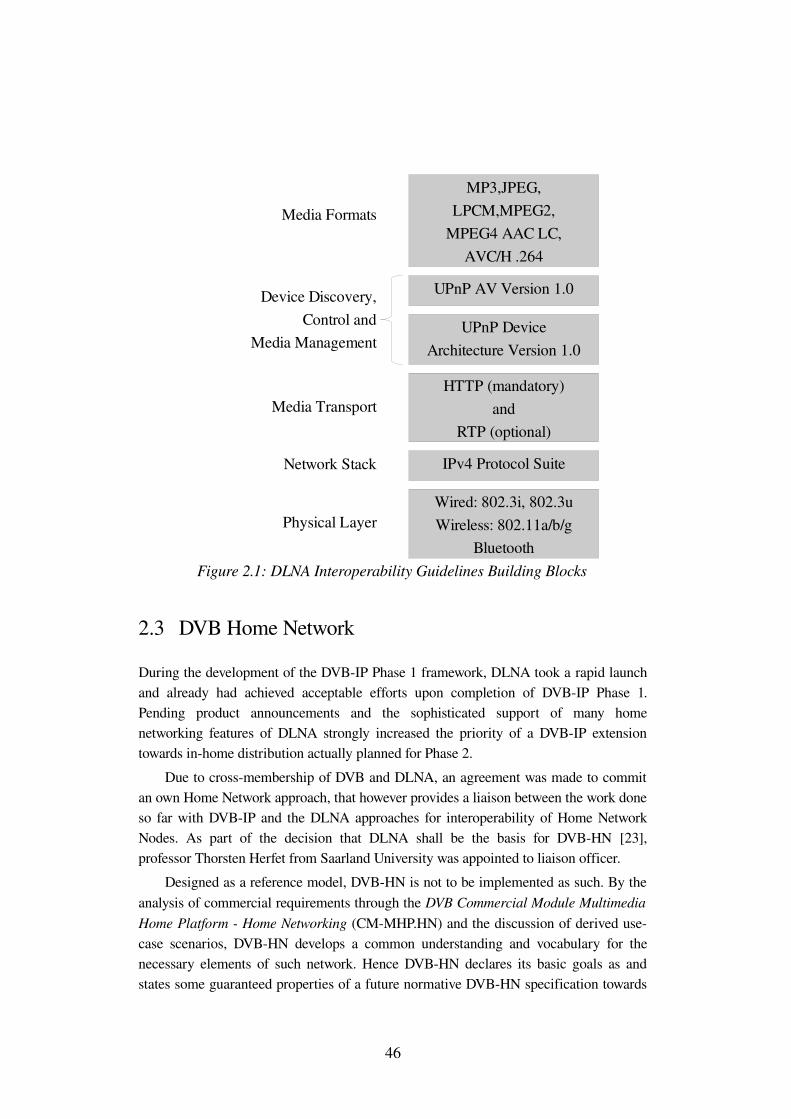
2.3 DVB Home Network
During the development of the DVBIP Phase 1 framework, DLNA took a rapid launch and already had achieved acceptable efforts upon completion of DVBIP Phase 1. Pending product announcements and the sophisticated support of many home networking features of DLNA strongly increased the priority of a DVBIP extension towards inhome distribution actually planned for Phase 2.
Due to crossmembership of DVB and DLNA, an agreement was made to commit an own Home Network approach, that however provides a liaison between the work done so far with DVBIP and the DLNA approaches for interoperability of Home Network Nodes. As part of the decision that DLNA shall be the basis for DVBHN [23], professor Thorsten Herfet from Saarland University was appointed to liaison officer.
Designed as a reference model, DVBHN is not to be implemented as such. By the analysis of commercial requirements through the DVB Commercial Module Multimedia Home Platform Home Networking (CMMHP.HN) and the discussion of derived usecase scenarios, DVBHN develops a common understanding and vocabulary for the necessary elements of such network. Hence DVBHN declares its basic goals as and states some guaranteed properties of a future normative DVBHN specification towards
46
Figure 2.1: DLNA Interoperability Guidelines Building Blocks
MP3,JPEG,LPCM,MPEG2,
MPEG4 AAC LC,AVC/H .264
UPnP AV Version 1.0
UPnP DeviceArchitecture Version 1.0
HTTP (mandatory)and
RTP (optional)
IPv4 Protocol Suite
Wired: 802.3i, 802.3uWireless: 802.11a/b/g
Bluetooth
Media Formats
Device Discovery,Control and
Media Management
Media Transport
Network Stack
Physical Layer
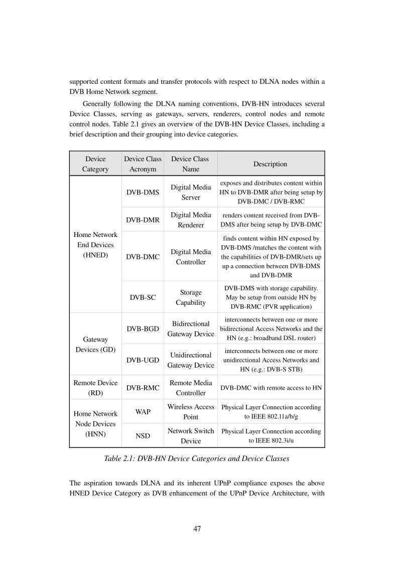
supported content formats and transfer protocols with respect to DLNA nodes within a DVB Home Network segment.
Generally following the DLNA naming conventions, DVBHN introduces several Device Classes, serving as gateways, servers, renderers, control nodes and remote control nodes. Table 2.1 gives an overview of the DVBHN Device Classes, including a brief description and their grouping into device categories.
Device Category
Device Class Acronym
Device Class Name
Description
Home Network End Devices
(HNED)
DVBDMSDigital Media
Server
exposes and distributes content within HN to DVBDMR after being setup by
DVBDMC / DVBRMC
DVBDMRDigital Media
Rendererrenders content received from DVB
DMS after being setup by DVBDMC
DVBDMCDigital Media
Controller
finds content within HN exposed by DVBDMS /matches the content with the capabilities of DVBDMR/sets up up a connection between DVBDMS
and DVBDMR
DVBSCStorage
Capability
DVBDMS with storage capability. May be setup from outside HN by
DVBRMC (PVR application)
Gateway Devices (GD)
DVBBGDBidirectional
Gateway Device
interconnects between one or more bidirectional Access Networks and the
HN (e.g.: broadband DSL router)
DVBUGDUnidirectional
Gateway Device
interconnects between one or more unidirectional Access Networks and
HN (e.g.: DVBS STB)
Remote Device (RD)
DVBRMCRemote Media
ControllerDVBDMC with remote access to HN
Home Network Node Devices
(HNN)
WAPWireless Access
PointPhysical Layer Connection according
to IEEE 802.11a/b/g
NSDNetwork Switch
DevicePhysical Layer Connection according
to IEEE 802.3i/u
Table 2.1: DVBHN Device Categories and Device Classes
The aspiration towards DLNA and its inherent UPnP compliance exposes the above HNED Device Category as DVB enhancement of the UPnP Device Architecture, with
47
the single device classes referring to modified UPnP AV MediaServers, MediaRenderers and Control Points.
The following clauses give an overview of the propositions made in DVBHN with respect to the yet given introductions on UPnP and DLNA, including hints to DVBIP as introduced in section 2.4.
DVBHN Networking
Since DVBIP only defines the delivery of DVBIP services over broadband access networks to DVBIP Home Network End Devices (HNEDs), DVBHN Networking must enable the inhome distribution of DVBIP services via an appropriate protocol suite. The explicitly stated compatibility to DLNA leaves the IPv4 protocol stack as only option. Though it must be mentioned that DVBHN requires its Device Classes only to support two DLNA physical layers, namely Ethernet (according to IEEE 802.3) and Wireless LAN (according to IEEE 802.11).
DVBHN Quality of Service
DVBHN introduces its overall design goal towards QoS, not to degrade the overall performance of transmission. This shall be achieved through quickly applicable forward error correction mechanisms and for the first phase of DVBHN by a prioritized QoS solution, based on DLNA guidelines. Generally, prioritized QoS only cares for a relative preference and makes no absolute guarantees towards bandwidth or latency of a particular flow.
That is DLNA defines four QoS levels, which are identified by the different DLNA Device Classes and resulting transfer modes. The highest DLNA QoS level (level 3) is reserved for RealTime Transfer Control Protocol (RTCP) messages that are sent from DLNA Media Renderers to DLNA Media Servers in order to control the flow of a streaming transfer. Consequently DLNA QoS level 2 is reserved for streaming transfer, which includes audio and AV streams that are to be rendered immediately to the user. DLNA QoS level 1 (interactive transfer) is bound to content without realtime characteristics like still pictures for example. The lowest DLNA QoS level 0 is reserved for background transfer of filebased content at the maximum rate of the receiving device.
As future topic for QoS in DVBHN, a parametrized approach is announced, with parametrized QoS usually making absolute guarantees for the transfer of a flow in terms of minimal bandwidth and/or maximum latency.
Regarding the very timesensitive nature of DVB content, the latter QoS approach is preferable to match DVB's realtime requirements. Note that DVBIP currently uses the Differentiated Services (DiffServ) mechanism, which uses the Type of Service field of
48
IP to indicate the type of traffic to intermediary devices, which only might be configured to treat this content with a higher priority.
DVBHN Media Formats
The supported media formats by DVBHN are defined by reference to [24] and [25]. [24] offers the guidelines for DVB services that follow the MPEG2 Transport Stream syntax. Also it introduces a class model for Integrated ReceiverDecoder (IRD) devices and makes an appointment towards the minimum decoding abilities for IRDs of one class. Additionally [24] defines the video and audio bitstream requirements for each IRD class. The class model is based on the overall coding properties of one particular DVB service, uniquely determined by the used audio and video coding format, the underlying video level and video profile, the actual frame rate, the chosen aspect ratio, as well as Luminance and Chrominance information. DVB services that are coded following the guidelines given in [24] may be delivered to DVBHN via a Unidirectional Gateway Device (UGD) (for example a DVBS tuner) or via the DVBIP Infrastructure (DVBIPI).
[25] defines guidelines for the usage of advanced audio and video compression algorithms in DVB services delivered directly over IP protocols without the use of an MPEG2 Transport Stream envelope. Instead of MPEG2 TS the system layer given in [25] is based on the RealTime Transport Protocol, according to the actual video or audio payload type. DVB services encoded in a way compliant to [25] may enter DVBHN via some Bidirectional Gateway Device (BGD), for example a broadband router providing a link to a broadband Access Network.
Conclusions for DVBHN are the necessary support of traditional and advanced video and audio coding formats, encapsulated within MPEG2 TS and advanced video and audio coding formats encapsulates within RTP packets. Regarding DLNA compatibility of DVBHN in the field of supported content formats, DLNA not yet supports all of the stream classes defined in [24] and [25]. On the other hand not all DLNA content formats are supported by DVBHN rendering devices. Due to the distinct goal of DVBHN to establish a liaison between DVB services on a home network and DLNA compliant devices, DVBHN commits itself to provide DLNA compatible rendering devices with DVB services in a way mandatory or at least optional to DLNA. Further conclusions towards UPnP can not be made due to UPnP explicit independence of any content format.
Content Protection
DVBHN employs the DVB Content Protection and Copy Management (DVBCPCM) [26] system to ensure content protection. DVBCPCM applies to content after it has been acquired. Other protection mechanisms formally applied to content are not within
49
the scope of DVBCPCM. DVBCPCM distinguishes a local environment and the so called Authorized Domain (AD) as its fundamental boundaries of control. The AD represents one or more DVBCPCM compliant devices, which can be uniquely identified. DVBCPCM controlled content in that sense is bounded to its so called Usage State Information, which identifies the content's ability to be displayed, copied or moved to an AD device.
UPnP implements Content Protection through employment of the UPnP Device Security Service (DSS) [27] in conjunction with the UPnP Security Console Service (SCS) [28]. DSS provides actions that enable for authentication and authorization, as well as replay prevention and privacy of SOAP messages. The UPnP approach rather deals with the potential weaknesses of UPnP device control than with a sophisticated Content Protection mechanism. Authorization is dealt with on device level and not on the level of a single piece of content.
Transport Protocols and Session Management
DVBHN distinguishes between isochronous streamed data and downloaded data which is not retrieved in realtime. Anticipating the relation to UPnP, there is currently no significant thematic accordance to Transport Protocols and Session Management in UPnP, except for the AVTS dependency of either push protocols (server side) or pull protocols (renderer side).
DVBHN considers two potential sources of media that has to be isochronously streamed. At first, DVBIP Phase 1 and its inherent MPEG2 Transport Stream format, delivered over UDP shall be supported. In version 1.3.1 of the DVBIP Infrastructure, RTP is optional for the first time, assuming a managed IP network that can guarantee certain values for packet loss rate, jitter and delivers UDP datagrams in the order they have been sent. DVBIP delivers DVB services of type Live Media Broadcast using IPMulticast, which requires the Internet Group Management Protocol (IGMP) version 3 as session management protocol. The two further DVBIP service types, namely Content on Demand (CoD) and Media Broadcast with Trick Modes (MBwTM) use RTSP to control the stream flow. Content that is delivered via such DVBIP compliant Bidirectional Gateway Device (BGD) will be accessed by DVBHN defined clients directly using the above native protocols. Optionally this content will be made available to attached DLNA devices implementing the DLNA's optional RTSP/RTP/UDP connectivity. As second source for DVB streams, DVBHN considers any DVB Unidirectional Gateway Device like a DVBS Receiver. DVBHN guarantees for content that stems from such UGD to be mapped onto DVBHN, compatible to DLNA's optional RTSP/RTP/UDP connectivity. DVBHN states the support of HTTP as transport and session management protocol to be optional for DVBHN MediaServers.
In order to have access to DLNA Media Servers and their offered content, DVBDMRs will implement HTTP as transport and session management protocol.
50
Metadata
In order to enable the content discovery between DVNHN and DLNA Server and Renderer devices, DVBHN must and actually does support UPnP ContentDirectory Service (CDS) as metadata format. The remaining three DVBHN supported metadata formats are part of DVBIP Phase 1, namely Service Discovery and Selection (SD&S), Broadband Content Guide (BCG) and DVB Service Information (DVBSI) embedded in the delivered MPEG2 TS. SD&S will be explained in greater detail in section 2.4 as part of the introduction to DVBIP.
In addition to the pure support of UPnP CDS, DVBHN announces the HN specification to provide a mechanism to map metadata from different sources to UPnP CDS, including for example DVBSI. This mapping will be provided to DVBHN by one designated proxy server device.
Migration of DVBIP and DLNA to DVBHN
Following the above proposals, DVBHN depicts the stepwise migration of DVB content and DLNA interoperability. Assuming that there is currently a possible coexistence of both technologies in one home network segment, DVBHN proposes the following migration steps.
1. Adding DVBDMR functionality to DVBIP HNED: Assuming DVBIP compliant HNEDs and DLNA Media Servers attached to one IP home network, as a first step DVBHN adds DVBDMR functionality to the DVBIP HNED. Implementing DVBDMR shall enable the DVBIP HNED to render content that is available from DLNA Media Servers. This surely includes the implementation of DVBDMC functionality within the DVBIP HNED or the compliance of DVBDMR with DLNA Media Controllers. Consequently either approach must provide the DLNA and implied UPnP device and service discovery and description mechanisms, including HTTP as transfer and session management protocol and the minimum DLNA content format requirements.
2. Adding transcoding functionality to DVBIP BGD and DVB UGD: Introducing DVB content to DLNA Media Servers and Media Renderers shall be achieved by adding transcoding functionality to existing gateways, connecting DVBHN to one or more bidirectional and unidirectional Access Networks. This includes a possible adaption of the content format, the transmission protocol and the content description in order to make DVB content available to DLNA devices. DVBDMR and DVBDMS devices shall still support all native DVB and DVBIP mechanisms to access DVB content via an enhanced UGD and BGD.
51
Summary DVBHN
The yet made observations on the DVBHN reference model already provide a new perspective for the application of the DVBS UPnP AV MediaServer developed within the present thesis. Regarding the transport protocol discussion and the optional support of DVBDMS for HTTP, the DVBS UPnP AV MediaServer actually implements HTTP as transfer and session management protocol and obviously provides all steps in UPnP Networking. Consequently it probably might be integrated with little effort into DVBHN in order to serve as DVBHN gateway for streamed content received via the DVBS UGD.
Additionally the announcement for a proxy server instance in DVBHN for a common conversion of metadata to UPnPCDS partially meets the current current design goals of the DVBS UPnP AV MediaServer, since it already has to provide a mapping between DVBSI and CDS.
2.4 DVBIP
Introduction
Maintaining today's most valuable technologies for digital video broadcast, the DVB Project undeviatingly makes great efforts to enhance its existing framework of open digital television standards. Working to strict commercial requirements makes it inevitable for DVB to focus on environments that enable a highly reliable access to many viewers, while facilitating economies of scale. Classical environments like Satellite and Cable still meet these requirements very well, which is approved by recent efforts to apply advanced coding standards to these classical media.
In spite of the rapidly growing deployment of highbandwidth internet connections, the current IP infrastructure does not yet entirely meet DVB's requirements for a reliable access to many viewers. Considering the path from a potential Content Service Provider to the viewer, the current IP infrastructure does not guarantee for specific timing constraints and the availability of technology that allows for the broadcast distribution of services. Although it is indisputable that the IP infrastructure will meet these requirements in the near future.
Raising the consumer's awareness for IPTV, already a considerable amount of Internet Service Providers (ISP) offers proprietary solutions that are most often merchandised in addition to VoiceoverIP offerings, the so called Triple Play. That is the subscription to either ISP will require specific hard or software, which will in most cases not be reusable for service offerings from another ISP.
Considering the viewer's need to buy a piece of hardware and plug it to some available inhome BGD in order to browse available AV content from a variety of
52
Content Service Providers (CSP), DVB published the DVBIP Phase 1 handbook, which meanwhile has developed to Phase 1.3. Like other DVB reference documents, DVBIP constitutes an open industry standard. Assuming current and future IPTV applications being somehow derived from one of the classical DVB unidirectional Access Networks, DVBIP introduces a normative framework for the transport of MPEG2 Transport Stream based DVB services over IP based networks.
DVBIP Phase 1.3 already covers a complete endtoend transmission, defining a new set of protocols and service description mechanisms. Maintaining the key knowledge of distributing DVB services in a highly reliable manner, DVB incorporates this knowledge by specifying normative limits for packet jitter, packet loss and Multicast timing for the underlying IP network.
The following discourse introduces DVBIP in order to supplement the toplevel design goals of DVBHN with more detail and to give a glimpse of how some of these goals may actually be approached.
System Structure
DVBIP Phase 1.3 is designed to deliver MPEG2 Transport Stream (MTS) based DVB services over bidirectional IP networks. In particular DVBIP addresses three DVB service types, namely Live Media Broadcast (LMB), Media Broadcast with Trick Modes (MBwTM) and Content on Demand (CoD) services. DVBIP defines the sink for these three service types as Home Network End Device (HNED), which is directly connected to a network interface referred to as Internet Protocol Infrastructure Interface 1 (IPI1). By abstracting all intermediary network properties, the normative requirements given in DVBIP Phase 1.3 apply to IPI1.
In order to describe the mutual relations in the domain where the DVB content is consumed, DVBIP defines three additional IP interface types that constitute the DVBIP Home Network Reference Model. DVBIP Phase 1.3 already refers to DVBHN, while Phase 1.3 itself does not address any other delivery path than the direct path from a Delivery Network Device (DNG) to the HNED. Though bridging interfaces like network switches are allowed in the path from DNG to the HNED unless they do not violate the overall requirements for IPI1.
Figure 2.2 shows the DVBIP Home Network Reference Model, giving the mutual relation between included elements marginal to the Delivery Network.
53
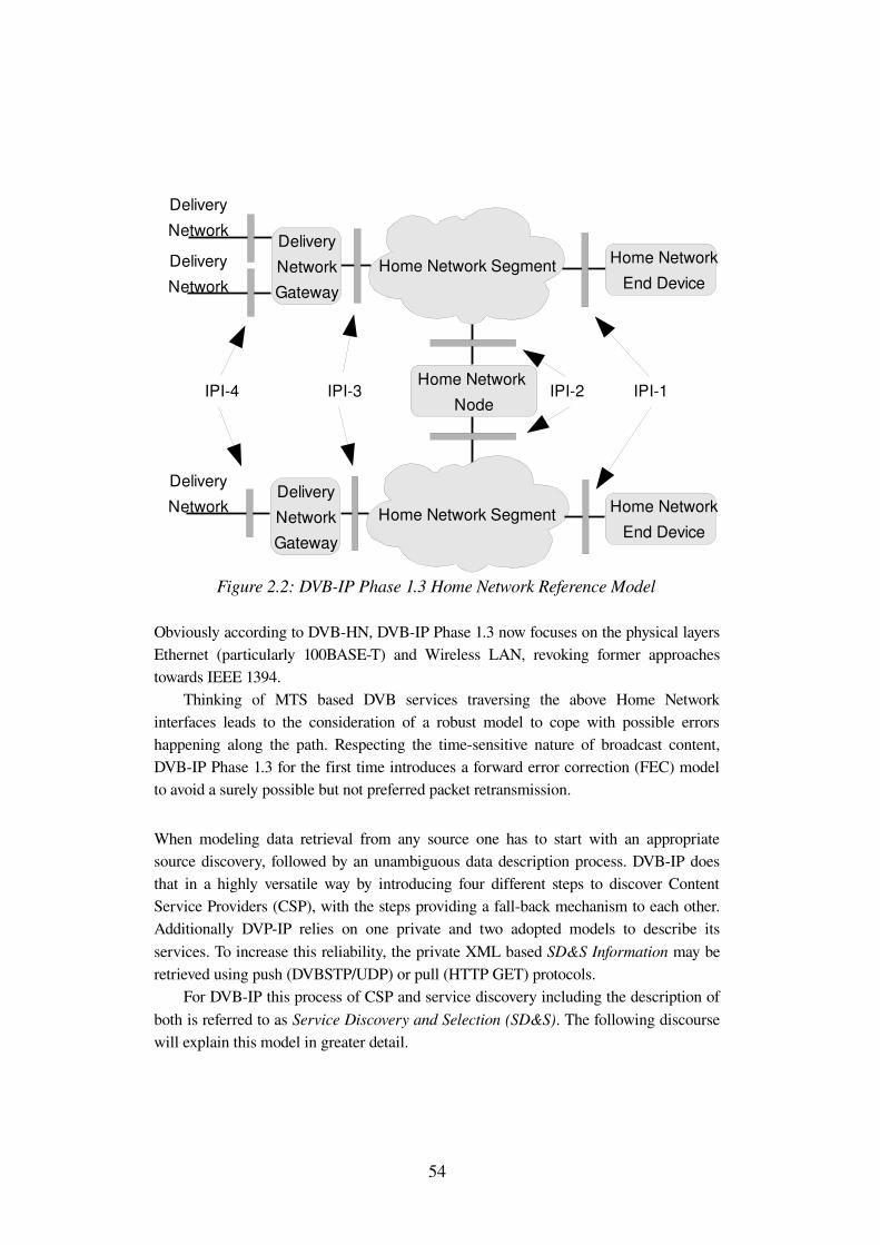
Obviously according to DVBHN, DVBIP Phase 1.3 now focuses on the physical layers Ethernet (particularly 100BASET) and Wireless LAN, revoking former approaches towards IEEE 1394.
Thinking of MTS based DVB services traversing the above Home Network interfaces leads to the consideration of a robust model to cope with possible errors happening along the path. Respecting the timesensitive nature of broadcast content, DVBIP Phase 1.3 for the first time introduces a forward error correction (FEC) model to avoid a surely possible but not preferred packet retransmission.
When modeling data retrieval from any source one has to start with an appropriate source discovery, followed by an unambiguous data description process. DVBIP does that in a highly versatile way by introducing four different steps to discover Content Service Providers (CSP), with the steps providing a fallback mechanism to each other. Additionally DVPIP relies on one private and two adopted models to describe its services. To increase this reliability, the private XML based SD&S Information may be retrieved using push (DVBSTP/UDP) or pull (HTTP GET) protocols.
For DVBIP this process of CSP and service discovery including the description of both is referred to as Service Discovery and Selection (SD&S). The following discourse will explain this model in greater detail.
54
Figure 2.2: DVBIP Phase 1.3 Home Network Reference Model
Home Network Segment
Home Network Node
Home Network Segment
Home Network End Device
Home Network End Device
Delivery Network Gateway
Delivery Network Gateway
Delivery Network
Delivery Network
Delivery Network
IPI4 IPI3 IPI2 IPI1
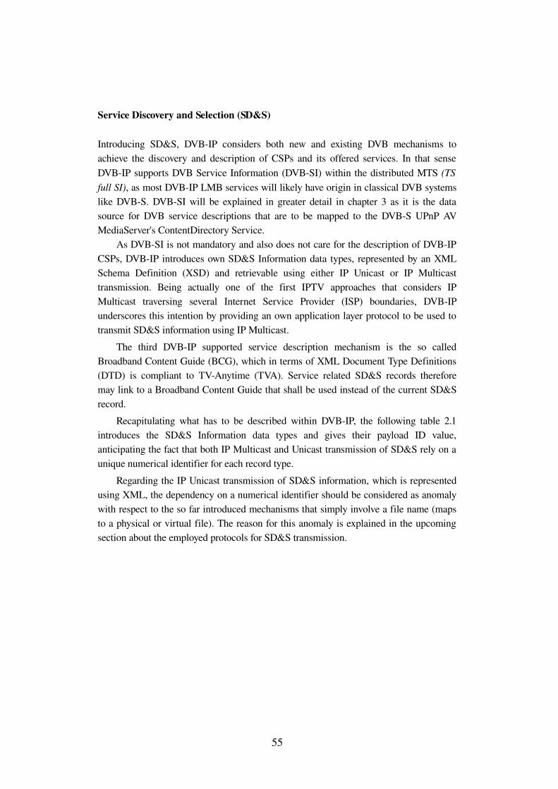
Service Discovery and Selection (SD&S)
Introducing SD&S, DVBIP considers both new and existing DVB mechanisms to achieve the discovery and description of CSPs and its offered services. In that sense DVBIP supports DVB Service Information (DVBSI) within the distributed MTS (TS full SI), as most DVBIP LMB services will likely have origin in classical DVB systems like DVBS. DVBSI will be explained in greater detail in chapter 3 as it is the data source for DVB service descriptions that are to be mapped to the DVBS UPnP AV MediaServer's ContentDirectory Service.
As DVBSI is not mandatory and also does not care for the description of DVBIP CSPs, DVBIP introduces own SD&S Information data types, represented by an XML Schema Definition (XSD) and retrievable using either IP Unicast or IP Multicast transmission. Being actually one of the first IPTV approaches that considers IP Multicast traversing several Internet Service Provider (ISP) boundaries, DVBIP underscores this intention by providing an own application layer protocol to be used to transmit SD&S information using IP Multicast.
The third DVBIP supported service description mechanism is the so called Broadband Content Guide (BCG), which in terms of XML Document Type Definitions (DTD) is compliant to TVAnytime (TVA). Service related SD&S records therefore may link to a Broadband Content Guide that shall be used instead of the current SD&S record.
Recapitulating what has to be described within DVBIP, the following table 2.1 introduces the SD&S Information data types and gives their payload ID value, anticipating the fact that both IP Multicast and Unicast transmission of SD&S rely on a unique numerical identifier for each record type.
Regarding the IP Unicast transmission of SD&S information, which is represented using XML, the dependency on a numerical identifier should be considered as anomaly with respect to the so far introduced mechanisms that simply involve a file name (maps to a physical or virtual file). The reason for this anomaly is explained in the upcoming section about the employed protocols for SD&S transmission.
55
Payload ID value SD&S record carried Acronym0x00 Reserved n.a
0x01 Service Provider Discovery Record SPDR
0x02 Broadcast Discovery Record BDR
0x03 CoD Discovery Record CDR
0x04 "Services from other Service Providers" Record SSPDR
0x05 Package Discovery Record PDR
0x06 BCG Discovery Record BCGDR
0x07 to 0xEF Reserved n.a
0xF0 to 0xFF User Private n.a
Table 2.2: SD&S data types and assigned payload ID values
SD&S Fragmentation
Well aware of the probable substantial size of some of these records, DVBIP introduces a twolayer fragmentation model. The first layer directly applies to a SD&S XML record and consists of segments. Segments are uniquely identified through their segment_id value and their version number in conjunction with the payload ID value of the superior SD&S record. Except for the SPDR, DVBIP does not restrict the fragmentation into segments unless each segment constitutes a valid XML document in terms of the given SD&S XSD. The Service Provider Discovery Record may however only be segmented in a way that it either covers exactly one Service Provider or all Service Providers that are available from one entry point.
This first fragmentation layer addresses a possible need to group for example a particular set of LMB services, with the set representing an actual physical channel structure of a satellite transponder. Taking this example further, the section layer may also become important if changes are applied to SD&S information. Thinking of a not segmented BDR that represents the complete LMB offering of one satellite, possibly including over a thousand service entries and an HNED population of several ten thousands; the consecutive detection of such change by an HNED population could cause a severe impact on the operational availability of a Service Provider.
The second fragmentation layer applies to segments by introducing an even smaller unit, namely the section. Sections are uniquely identified through their section_number and last_section_number value with respect to the unique identifiers of the superior segment. The section layer addresses the DVB SD&S Transport Protocol (DVBSTP) for IP Multicast transmission. Since DVBSTP is built on top of UDP datagrams, it must care for the fixed UDP datagram size with respect to the underlying network layer's
56
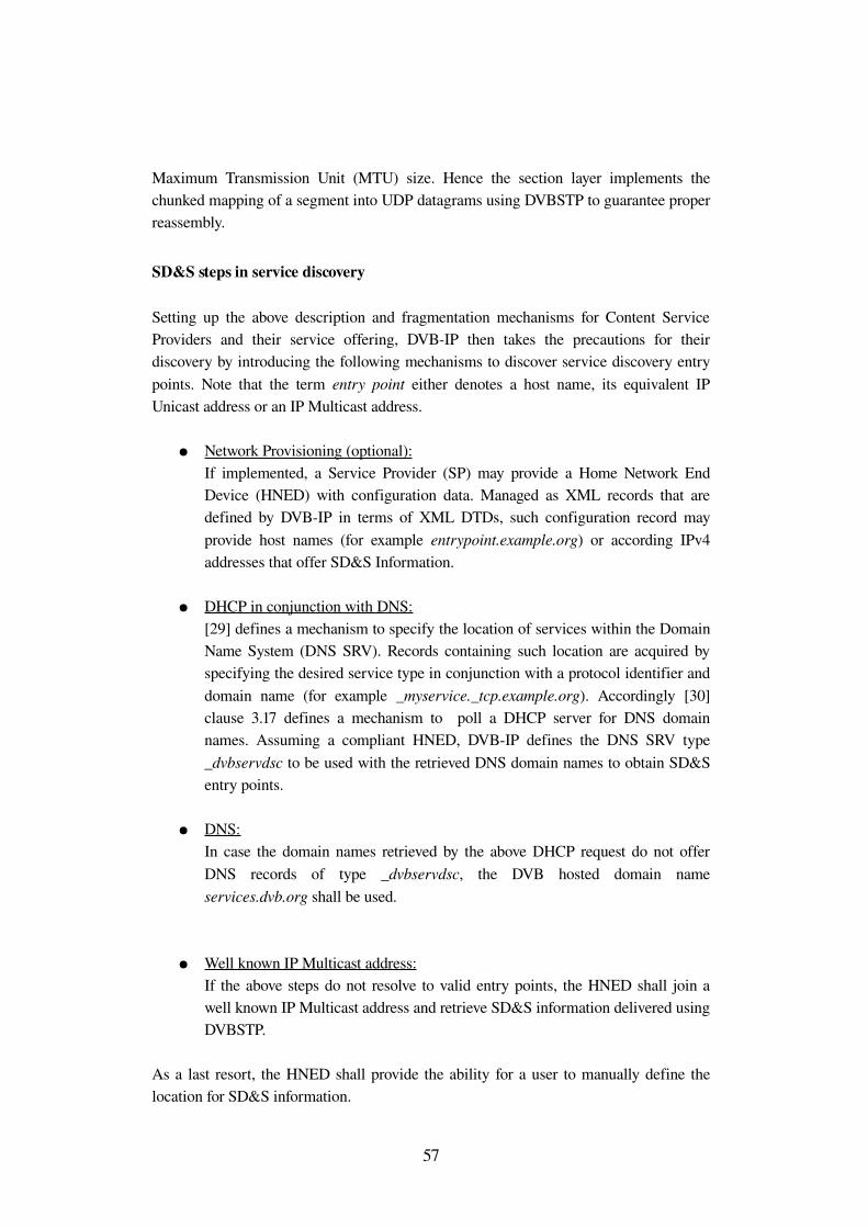
Maximum Transmission Unit (MTU) size. Hence the section layer implements the chunked mapping of a segment into UDP datagrams using DVBSTP to guarantee proper reassembly.
SD&S steps in service discovery
Setting up the above description and fragmentation mechanisms for Content Service Providers and their service offering, DVBIP then takes the precautions for their discovery by introducing the following mechanisms to discover service discovery entry points. Note that the term entry point either denotes a host name, its equivalent IP Unicast address or an IP Multicast address.
● Network Provisioning (optional): If implemented, a Service Provider (SP) may provide a Home Network End Device (HNED) with configuration data. Managed as XML records that are defined by DVBIP in terms of XML DTDs, such configuration record may provide host names (for example entrypoint.example.org) or according IPv4 addresses that offer SD&S Information.
● DHCP in conjunction with DNS: [29] defines a mechanism to specify the location of services within the Domain Name System (DNS SRV). Records containing such location are acquired by specifying the desired service type in conjunction with a protocol identifier and domain name (for example _myservice._tcp.example.org). Accordingly [30] clause 3.17 defines a mechanism to poll a DHCP server for DNS domain names. Assuming a compliant HNED, DVBIP defines the DNS SRV type _dvbservdsc to be used with the retrieved DNS domain names to obtain SD&S entry points.
● DNS: In case the domain names retrieved by the above DHCP request do not offer DNS records of type _dvbservdsc, the DVB hosted domain name services.dvb.org shall be used.
● Well known IP Multicast address: If the above steps do not resolve to valid entry points, the HNED shall join a well known IP Multicast address and retrieve SD&S information delivered using DVBSTP.
As a last resort, the HNED shall provide the ability for a user to manually define the location for SD&S information.
57
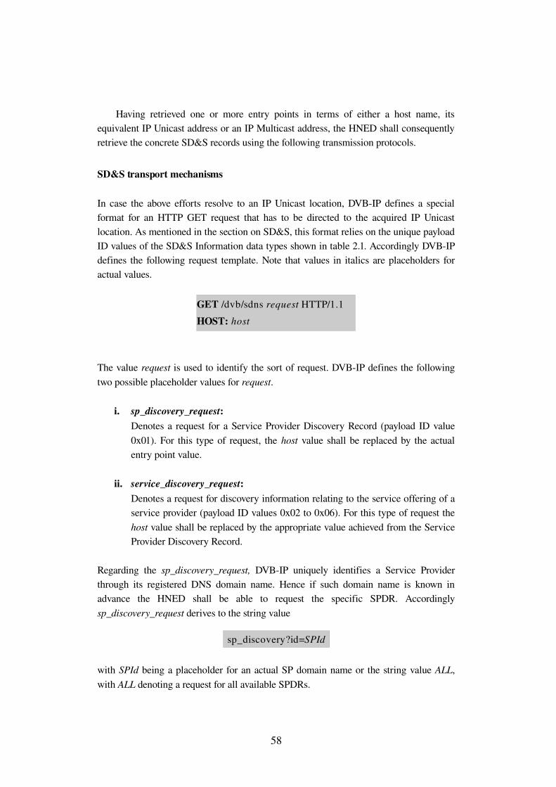
Having retrieved one or more entry points in terms of either a host name, its equivalent IP Unicast address or an IP Multicast address, the HNED shall consequently retrieve the concrete SD&S records using the following transmission protocols.
SD&S transport mechanisms
In case the above efforts resolve to an IP Unicast location, DVBIP defines a special format for an HTTP GET request that has to be directed to the acquired IP Unicast location. As mentioned in the section on SD&S, this format relies on the unique payload ID values of the SD&S Information data types shown in table 2.1. Accordingly DVBIP defines the following request template. Note that values in italics are placeholders for actual values.
The value request is used to identify the sort of request. DVBIP defines the following two possible placeholder values for request.
i. sp_discovery_request: Denotes a request for a Service Provider Discovery Record (payload ID value 0x01). For this type of request, the host value shall be replaced by the actual entry point value.
ii. service_discovery_request: Denotes a request for discovery information relating to the service offering of a service provider (payload ID values 0x02 to 0x06). For this type of request the host value shall be replaced by the appropriate value achieved from the Service Provider Discovery Record.
Regarding the sp_discovery_request, DVBIP uniquely identifies a Service Provider through its registered DNS domain name. Hence if such domain name is known in advance the HNED shall be able to request the specific SPDR. Accordingly sp_discovery_request derives to the string value
with SPId being a placeholder for an actual SP domain name or the string value ALL, with ALL denoting a request for all available SPDRs.
58
GET /dvb/sdns request HTTP/1.1HOST: host
sp_discovery?id=SPId
An SPDR retrieved by the above sp_discovery request links to the service offering of a Service Provider. If the SPDR links to a Unicast resource, it also specifies the segment_id values of a given SD&S record. The specification of a segment version however is optional. Hence the request for service information derives in a way compliant to the DVBIP fragmentation level 1. That is the HNED may request a particular segment_id and version value according to its superior payload ID. Please refer to [31] for the actual replacement values for service_discovery_request.
If one of the steps in SD&S service discovery resolves to an IP Multicast address or a SPDR retrieved via HTTP provides a push location, the HNED shall retrieve SD&S information by joining the respective Multicast Group, using the Internet Group Management Protocol (IGMP). Picking up the classical broadcast idea of repeatedly delivering data in a continuous cycle, DVBSTP datagrams are carouseled to the HNED, which consequently needs to reassemble the single SD&S sections. Hence DVBSTP relies on all values that uniquely identify SD&S sections and therefore defines the appearance as UDP payload by fixed field sizes at fixed field positions immediately following the UDP header. As upper bound for the reception of all SD&S information available from one entry point, DVBIP defines the maximum carousel cycle time as 30 seconds. Please refer to [31] for the exact DVBSTP syntax.
DVBIP advises both push and pull transmission of SD&S information to use a suitable compression. DVBSI adopts the TVAnytime approach to XML compression, by recommending the employment of the Binary MPEG Format for XML (BiM). BiM basically relies on the XSD of an XML language and uses the XSD in conjunction with the actual XML document to generate a very compact binary coding of this XML document. That is XSD elements and attributes are encoded using only a few bits while actual values are typically encoded using dedicated encoders according to the data type. BiM encoding is also a current field of implementation of the Saarland University Telecommunications Lab with a first application study of BiM coding on SD&S already available at [32].
Service selection
As a reminder, DVBIP Phase 1.3 defines its three supported service types as Live Media Broadcast (LMB), Media Broadcast with Trick Modes (MBwTM) and Content on Demand (CoD).
To access and to control each of the supported service types, DVBIP employs the application level RealTime Streaming Protocol (RTSP). RTSP is designed to initiate and control one or more data streams with realtime characteristics. Similar to other stream control applications (for example UPnP AVTS), RTSP models a state machine for its control servers in order to allow for staterelative control and timerelative navigation. Obviously the support for several simultaneous data streams requires a
59
session based behavior of both RTSP server and client. Therefore RTSP servers generate a pseudorandom session identifier to associate subsequent client requests with the according data streams and stream states. Thinking of UPnP, this behavior is implemented in terms of unique virtual instance identifiers for the AVTransport Service. Unless there is no further subset of functionality, this consideration shall only sample one overall requirement to stream control applications and protocols.
Considering the continuously varying and typically highbandwidth requirements of a DVBIP Content Service Provider, RTSP also provides load balancing through dynamic redirection of incoming stream requests.
One further characteristic of RTSP is the ability of servers posing requests to clients. DVBIP employs this feature for eventing purposes. Therefore DVBIP recommends the HNED to use a persistent TCP connection to enable communication that is initiated by the RTSP server. The practical application for eventing is the announcement of changes in SD&S information to currently connected clients.
Similar to HTTP, also RTSP defines request methods that specify the overall type of request, followed by a set of headers carrying the actual values like the session identifier, content type and resource location. DVBIP Phase 1.3 for the first time introduces direct mapping of MTS based DVB services into UDP and the application of a Forward Error Correction to the stream. This requires DVBIP to add the support for new header values understood by both RTSP server and client.
Summary DVBIP
Regarding the DVBIP Home Network model and its requirements for IPI1 (see figure 2.2), one may recognize the proximity to the classical DVB broadcast approaches, which in fact do not cover the interoperability of end devices. As DVB's first priority for the IP infrastructure may still be assumed to be the distribution of Live Media Broadcast content, the availability of IP Multicast technology for DVBIP is inevitable.
Considering the actual deployment of IP Multicast, the application of DVBIP Phase 1.3 will likely be restricted to the IP subnet of one ISP. A current example is the VDSL network structure of the Deutsche Telekom subsidiary company TOnline that already provides IP Multicast for this particular subnet and also employs that pseudobroadcast technology in conjunction with RTSP to deliver DTV services to its customers.
60

3 DVBS System Overview
3.1 Introduction
Looking at DVB's main transmission standards DVBS for Satellite, DVBC for Cable and DVBT for Terrestrial, DVBS may be considered the most valuable. With one satellite being able to cover a service area that includes large parts of Europe, the term economies of scale evolved to a whole new dimension for television broadcast. The deregulation of the satellite communications sector finally allowed for the joint usage of the FSS (fixed satellite service) and BSS (broadcast satellite service) band for downlink and uplink applications, which at last offered adequate bandwidth for a satisfactory DirectToHome (DTH) service offering. By colocating several satellites at a common orbital position, even the strict commercial backup requirements could be accomplished, which today guarantee for an unprecedented service availability.
Taking into account profitability aspects of service providers, introducing digital technologies to satellite communications allowed for a considerable reduction of bandwidth per service requirements and the ability for several services to share one physical channel. In fact this made the distribution of television and radio services via satellite more financially rewarding for privately financed television and radio service providers. Furthermore, the employment of a common service format for the DVB main transmission standards makes DVBS the main source for the retransmission of DVB services over terrestrial and cable networks.
Considering the viewer's need for high quality entertainment, the application of suitable error correction mechanisms to the common MPEG2 Transport Stream service format and advanced channel coding techniques, DVBS allows for a quasi errorfree broadcast service experience. All previously mentioned factors contribute to the DVBS most significant advantages for the customer, namely the independence of terrestrial infrastructure, a minimum of initial cost and no followup expenses.
The value of broadcasting television, radio and data services via satellite has been emphasized lately by the adoption of the DVBS2 standard. DVBS2 combines new channel coding schemes, higher order modulation and advanced FEC techniques in a variable manner. This results in a capacity gain in the order of 30 percent per transponder for a given set of physical parameters like bandwidth and radiated power, depending on the modulation scheme and code rate of the inner coder.
62
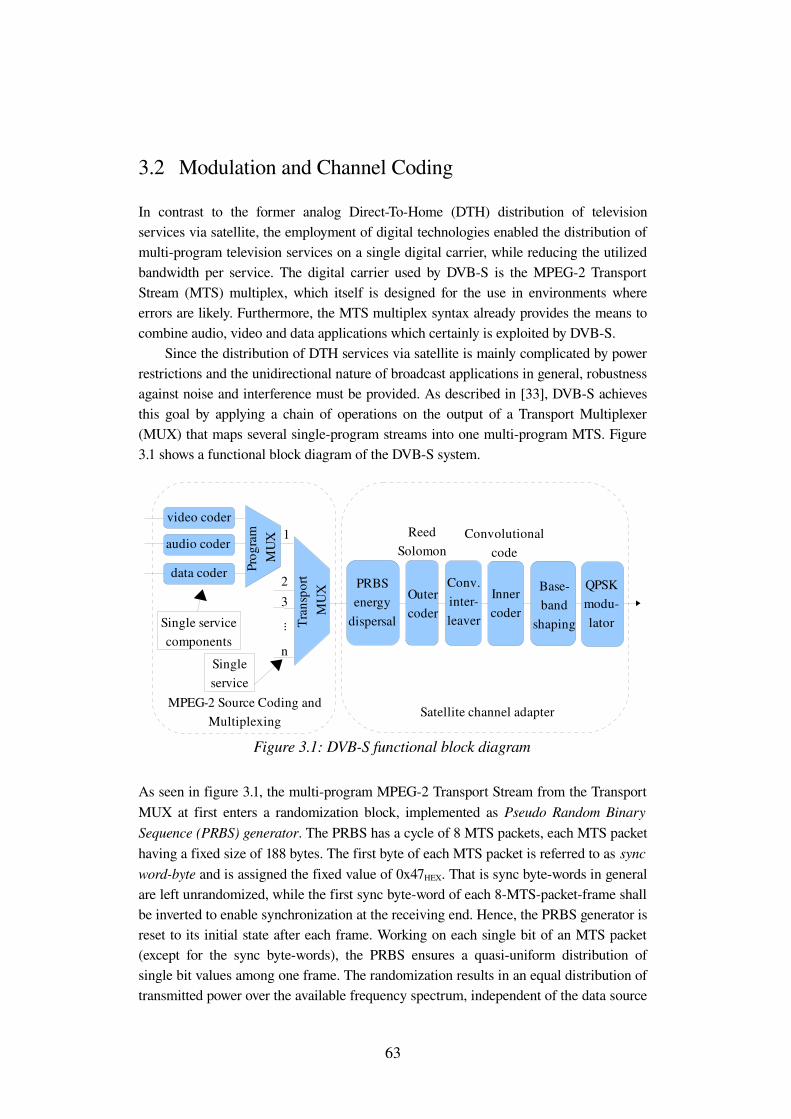
3.2 Modulation and Channel Coding
In contrast to the former analog DirectToHome (DTH) distribution of television services via satellite, the employment of digital technologies enabled the distribution of multiprogram television services on a single digital carrier, while reducing the utilized bandwidth per service. The digital carrier used by DVBS is the MPEG2 Transport Stream (MTS) multiplex, which itself is designed for the use in environments where errors are likely. Furthermore, the MTS multiplex syntax already provides the means to combine audio, video and data applications which certainly is exploited by DVBS.
Since the distribution of DTH services via satellite is mainly complicated by power restrictions and the unidirectional nature of broadcast applications in general, robustness against noise and interference must be provided. As described in [33], DVBS achieves this goal by applying a chain of operations on the output of a Transport Multiplexer (MUX) that maps several singleprogram streams into one multiprogram MTS. Figure 3.1 shows a functional block diagram of the DVBS system.
As seen in figure 3.1, the multiprogram MPEG2 Transport Stream from the Transport MUX at first enters a randomization block, implemented as Pseudo Random Binary Sequence (PRBS) generator. The PRBS has a cycle of 8 MTS packets, each MTS packet having a fixed size of 188 bytes. The first byte of each MTS packet is referred to as sync wordbyte and is assigned the fixed value of 0x47HEX. That is sync bytewords in general are left unrandomized, while the first sync byteword of each 8MTSpacketframe shall be inverted to enable synchronization at the receiving end. Hence, the PRBS generator is reset to its initial state after each frame. Working on each single bit of an MTS packet (except for the sync bytewords), the PRBS ensures a quasiuniform distribution of single bit values among one frame. The randomization results in an equal distribution of transmitted power over the available frequency spectrum, independent of the data source
63
Figure 3.1: DVBS functional block diagram
video coder
audio coder
data coder Prog
ram
MUX
Tran
spor
t M
UX
PRBSenergy
dispersal
Outercoder
Conv.interleaver
Innercoder
Baseband
shaping
QPSKmodulator...
1
23
n
MPEG2 Source Coding and Multiplexing
Satellite channel adapter
Single service components
Singleservice
Reed Solomon
Convolutionalcode
characteristics. Leaving an MTS totally unrandomized could cause frequently occurring bitsequences (physically represented by discrete voltage sequences) to translate into concentrations of energy at particular frequencies, which may result in interference in the receiver.
The second block of operation the so called outer coder applies a strong forward error correction (FEC) technique, which is designed to match the MTS packet format. Considering a pseudorandomized MTS multiplex as input, a shortened ReedSolomon error correction is employed as outer coding scheme. ReedSolomon (RS) codes operate on data symbols that contain several data bits and add redundancy to enable error detection and error correction. Hence RS codes are typically identified by the number of bits per symbol, the number of input symbols that are processed per cycle and the overall number of output symbols per cycle including redundancy symbols. DVBS employs RS coding that works on 8bit symbols of one 188byte MTS packet and adds 16 parity bytes, resulting in an error protected packet length of 204 bytes. This finally enables an Integrated Receiver Decoder (IRD) to correct up to eight single byte errors that may occur to one MTS packet during transmission.
In order to minimize the effect on a single MTS packet in case of burst errors, the 204byte error protected MTS packets are interleaved to spread single bytes of one packet over many interleaved packets. The employed convolutional interleaver is recommended to have a depth of 12 branches, with each branch providing an incremental delay for single byte values, starting with branch zero (no delay) that is reserved for the sync byteword.
As last step of the FEC process, DVBS involves convolutional coding, which cares for single bit errors. Consequently the convolutional coder adds up to one redundancy bit per data bit (code rate ½), which may be adjusted by puncturing the two outputs X and Y of this encoder. Both outputs X and Y are uniquely identified by a generator polynomial, which applies to the convolutional coder's constraint length 7. That is the convolutional coder has a 7 bit memory implemented as FIFO register. The two output branches X and Y are finally punctured, which denotes the transmission of only part of the output according to a fixed pattern. Puncturing yields the parallel output streams I and Q, with both streams including a fixed sequence of X and Ybits according to the desired code rate. As an example, code rate ½ results in an Istream that contains all Xbits, whereas the Qstream contains all Ybits. Code rate ¾ (3 input bits to the convolutional coder yield 4 output bits from the puncturing circuit) results in a subsequent Istream I: X1 Y2 and Qstream Q: Y1 X3. Note that code rate and resulting puncturing patterns shall be automatically detected by the receiver and do not need to be explicitly provided in order to establish a reception of DVBS services.
The above puncturing circuit produces two parallel output bitstreams. Single bit values from each bitstream are mathematically represented as Dirac delta functions and physically approximated by narrow voltage pulses, differing in sign for bit values 0 and 1. Obviously such pulse is finite in time, according to a fixed symbol duration. This limitation in the time domain leads to an infinite extension of a single pulse in the
64
frequency domain, which would cause a general cochannel distortion and the interference with subsequent and preceding symbols. That is the resulting frequency spectrum has to be delimited by appropriate filtering. DVBS employs so called square root raised cosine filtering (see [34] chapter 3.4.1) with a fixed rolloff factor of 0,35. This filter approximates the ideal case of a rectangular frequency spectrum shape by offering a tradeoff between low attenuation of the useful channel bandwidth and a steep decay close to adjacent channels. In that sense the rolloff factor denotes the excess bandwidth over the ideal rectangular solution with a rolloff factor of zero.
DVBS uses Quaternary Phase Shift Keying (QPSK) as preferred modulation scheme. QPSK distinguishes between four equidistant phase values for the modulated carrier and consequently each phase value can encode two bits as modulated symbol. The first bit of each modulated symbol refers to Ibits from the above puncturing circuit and accordingly the second bit to the Qbits. A QPSK signal is practically achieved as sum of two orthogonal (phase difference π/2) Binary Phase Shift Keying (BPSK) signals, each of which referring to one output branch of the puncturing circuit. Choosing a modulation scheme that can only represent four different symbols, constitutes a trade off between ruggedness against noise and the higher bandwidth requirements that result from higher symbol rates. Regarding the ruggedness against noise, the demodulation process separates the underlying BPSK signals by multiplying the QPSK input signal with local sine and cosine waves, which for each multiplication yields a term that is frequency independent and varies according to the applied phase shift. Having only half the amplitude of the incoming signal, these only phase dependent terms correspond to a voltage that is used to decide which bit value has been encoded. Obviously a closer phase spacing, as it is employed by higher order modulation schemes, would result in a worse distinguishable voltage level in presence of noise. To meet the bit error correcting capabilities of the convolutional inner coder, the four possible 2bit symbols are Gray coded. That is adjacent symbols only differ in one bit. This technique contributes to convolutional coding because if a symbol is received in error, it will contain only one erroneous bit if interferences altered the original phase value to an adjacent one.
3.3 MPEG2 Transport Stream
Choosing the MPEG2 Transport Stream (MTS) as common multiplex for the distribution on various media like satellite, terrestrial and cable networks can be considered as fundamental factor for the success of DVB systems. [35] defines the MTS as coding syntax that provides the means to synchronize the decoding and playback of audio and video data. The MTS is designed to carry multiple programs with one or more independent time bases as single data stream. The definition of the fixedlength 188byte Transport Stream packet as basic unit of an MTS, contributes to the second MTS design goal, namely the application in environments where errors are likely.
65
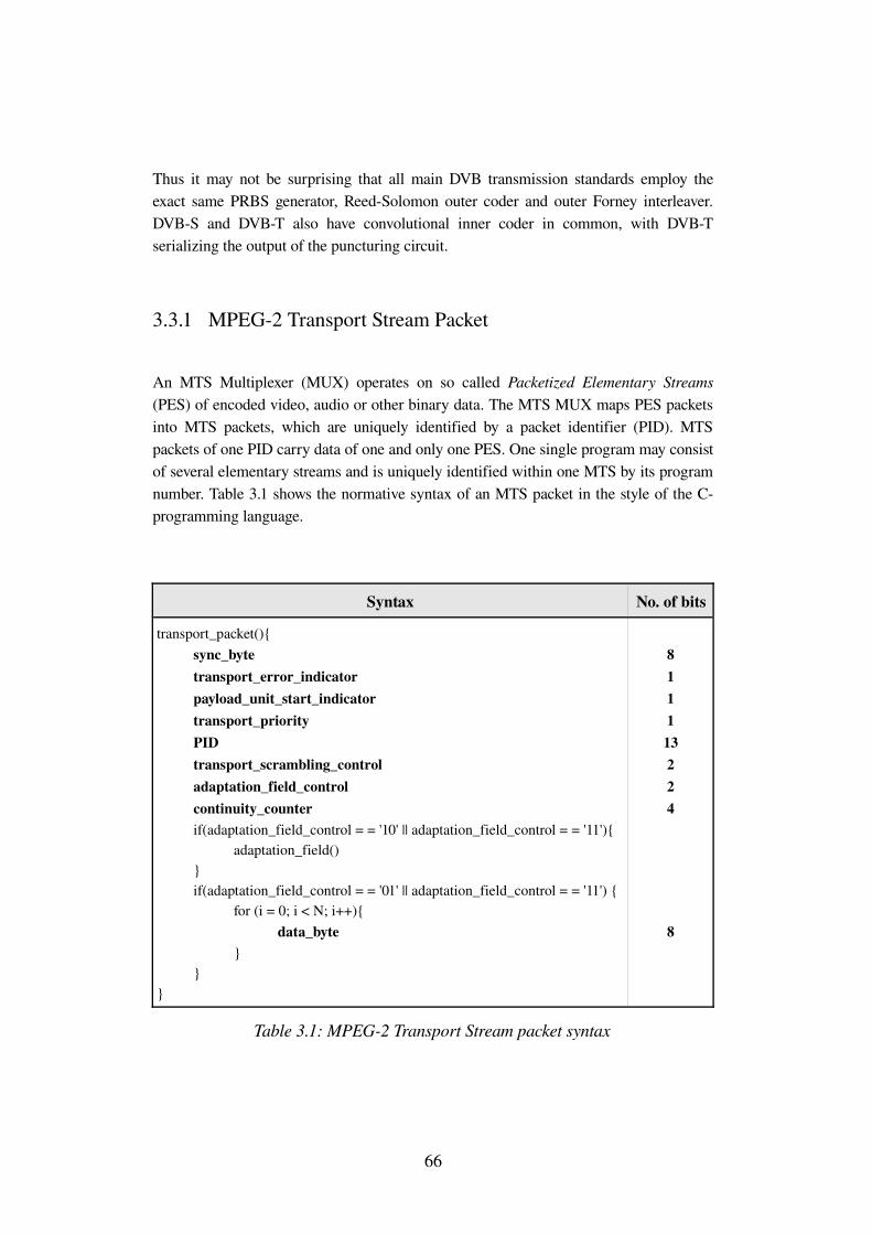
Thus it may not be surprising that all main DVB transmission standards employ the exact same PRBS generator, ReedSolomon outer coder and outer Forney interleaver. DVBS and DVBT also have convolutional inner coder in common, with DVBT serializing the output of the puncturing circuit.
3.3.1 MPEG2 Transport Stream Packet
An MTS Multiplexer (MUX) operates on so called Packetized Elementary Streams (PES) of encoded video, audio or other binary data. The MTS MUX maps PES packets into MTS packets, which are uniquely identified by a packet identifier (PID). MTS packets of one PID carry data of one and only one PES. One single program may consist of several elementary streams and is uniquely identified within one MTS by its program number. Table 3.1 shows the normative syntax of an MTS packet in the style of the Cprogramming language.
Syntax No. of bits
transport_packet(){ sync_byte transport_error_indicator payload_unit_start_indicator transport_priority PID transport_scrambling_control adaptation_field_control continuity_counter if(adaptation_field_control = = '10' || adaptation_field_control = = '11'){ adaptation_field() } if(adaptation_field_control = = '01' || adaptation_field_control = = '11') { for (i = 0; i < N; i++){ data_byte } } }
811113224
8
Table 3.1: MPEG2 Transport Stream packet syntax
66
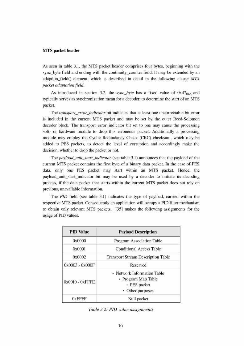
MTS packet header
As seen in table 3.1, the MTS packet header comprises four bytes, beginning with the sync_byte field and ending with the continuity_counter field. It may be extended by an adaption_field() element, which is described in detail in the following clause MTS packet adaptation field.
As introduced in section 3.2, the sync_byte has a fixed value of 0x47HEX and typically serves as synchronization mean for a decoder, to determine the start of an MTS packet.
The transport_error_indicator bit indicates that at least one uncorrectable bit error is included in the current MTS packet and may be set by the outer ReedSolomon decoder block. The transport_error_indicator bit set to one may cause the processing soft or hardware module to drop this erroneous packet. Additionally a processing module may employ the Cyclic Redundancy Check (CRC) checksum, which may be added to PES packets, to detect the level of corruption and accordingly make the decision, whether to drop the packet or not.
The payload_unit_start_indicator (see table 3.1) announces that the payload of the current MTS packet contains the first byte of a binary data packet. In the case of PES data, only one PES packet may start within an MTS packet. Hence, the payload_unit_start_indicator bit may be used by a decoder to initiate its decoding process, if the data packet that starts within the current MTS packet does not rely on previous, unavailable information.
The PID field (see table 3.1) indicates the type of payload, carried within the respective MTS packet. Consequently an application will occupy a PID filter mechanism to obtain only relevant MTS packets. [35] makes the following assignments for the usage of PID values.
PID Value Payload Description
0x0000 Program Association Table
0x0001 Conditional Access Table
0x0002 Transport Stream Description Table
0x0003 0x000F Reserved
0x0010 0xFFFE
• Network Information Table• Program Map Table
• PES packet• Other purposes
0xFFFF Null packet
Table 3.2: PID value assignments
67
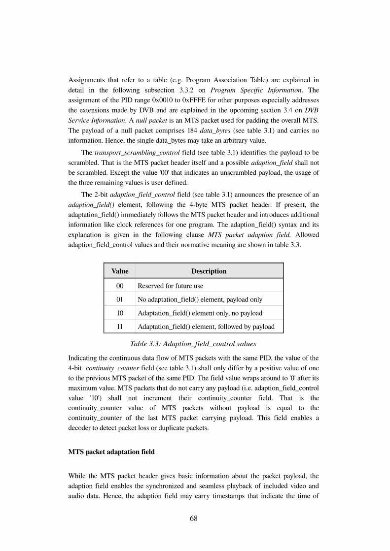
Assignments that refer to a table (e.g. Program Association Table) are explained in detail in the following subsection 3.3.2 on Program Specific Information. The assignment of the PID range 0x0010 to 0xFFFE for other purposes especially addresses the extensions made by DVB and are explained in the upcoming section 3.4 on DVB Service Information. A null packet is an MTS packet used for padding the overall MTS. The payload of a null packet comprises 184 data_bytes (see table 3.1) and carries no information. Hence, the single data_bytes may take an arbitrary value.
The transport_scrambling_control field (see table 3.1) identifies the payload to be scrambled. That is the MTS packet header itself and a possible adaption_field shall not be scrambled. Except the value '00' that indicates an unscrambled payload, the usage of the three remaining values is user defined.
The 2bit adaption_field_control field (see table 3.1) announces the presence of an adaption_field() element, following the 4byte MTS packet header. If present, the adaptation_field() immediately follows the MTS packet header and introduces additional information like clock references for one program. The adaption_field() syntax and its explanation is given in the following clause MTS packet adaption field. Allowed adaption_field_control values and their normative meaning are shown in table 3.3.
Value Description
00 Reserved for future use
01 No adaptation_field() element, payload only
10 Adaptation_field() element only, no payload
11 Adaptation_field() element, followed by payload
Table 3.3: Adaption_field_control values
Indicating the continuous data flow of MTS packets with the same PID, the value of the 4bit continuity_counter field (see table 3.1) shall only differ by a positive value of one to the previous MTS packet of the same PID. The field value wraps around to '0' after its maximum value. MTS packets that do not carry any payload (i.e. adaption_field_control value '10') shall not increment their continuity_counter field. That is the continuity_counter value of MTS packets without payload is equal to the continuity_counter of the last MTS packet carrying payload. This field enables a decoder to detect packet loss or duplicate packets.
MTS packet adaptation field
While the MTS packet header gives basic information about the packet payload, the adaption field enables the synchronized and seamless playback of included video and audio data. Hence, the adaption field may carry timestamps that indicate the time of
68
arrival of the byte containing the last bit of that time stamp at the MTS target decoder. Such time stamp is referred to as Program Clock Reference (PCR) and Original Program Clock Reference (OPCR). Note that only MTS packets with PID 0x0000, 0x0001 and 0x0010 to 0xFFFE (see table 3.2) are allowed to carry PCR fields.
Additionally the adaptation field provides the only stuffing mechanisms for PES data. Since an MTS packet has to comprise the fixed length of 188 bytes, PES data that does not complete an MTS packet payload must be padded. If padding is required, the normative elements of the adaption field are immediately followed by so called stuffing bytes (i.e. value '0xFF'), the number of which is indicated as difference of the adaptation_field_length value and the number of adaptation field data bytes.
In order to provide a target decoder further entry points for the setup of its playback procedure, the adaption field includes a random_access_indicator. Respecting the properties of the supported PES video and audio streams, the random_access_indicator announces the next PES packet to start with a video or audio access point. Access Point in the sense of an audio PES refers to the first byte of an audio frame (refer to [36] subsection 2.4.2.2) and accordingly in the sense of a video PES to the first byte of a video sequence header (refer to [37] subsection 6.1.1.6).
Assuming the classical case of one television program being repeatedly interrupted by advertisements, the adaptation field offers the ability to inform a target decoder about the upcoming splice between audio and video data that typically stems from a different source and consequently has different coding properties like PCR and bit rate. To ensure the seamless presentation in the case of an advertisement or the beginning of a new event, several elements of the adaption field are involved. At first, the splicing_point_flag will indicate the presence of the splice_countdown field. The splice_countdown specifies the remaining number of MTS packets of the same PID, immediately following the current MTS packet, until a splicing point is reached. Similar to the random_access_indicator, the payload of the MTS packet immediately following the MTS packet with the splice_countdown value '0' shall begin with the first byte of an audio or video access point (see random_access_indicator above).
To allow for a truly seamless presentation in presence of splices, which may need the target decoder to take some precautions in terms of buffer management and bit stream parameters, the announcement of a splice may be supplemented by additional parameters. The seamless_splice_flag indicates the presence of the splice_type and DTS_next_AU field. The splice_type field applies to a video PES and prepares the target decoder for the video bit rate (max_splice_rate) of the new video PES, immediately following the splicing point. Accordingly it specifies an amount of time (splice_decoding_delay), for which the last picture before the splicing point shall be presented to the viewer.
As the displacing PES that starts after the splicing point will presumably originate from a different source and accordingly will have another time base, the DTS_next_AU
69
(decoding time stamp next access unit) provides a link between the upcoming video access point and the current time base, before the splicing point is reached.
3.3.2 Program Specific information
Obviously, the possibility for multiple programs, each consisting of several elementary streams and the reconfiguration of the program offering at runtime, requires the multiplex to include a suitable lookup mechanism to discover and distinguish its current content. The MTS employs a virtual table mechanism, referred to as Program Specific Information (PSI), to achieve this goal. That is table is a generic term for a collection of smaller fragments, referred to as PSI section. A PSI table is by default fragmented into one or more PSI sections, with [35] providing the normative syntax and semantics for four different PSI section types and a normative template for privately defined section types. PSI sections have a maximum size of 1024 bytes, while privately defined sections may comprise 4096 bytes. Similar to video and audio binary data, PSI sections are mapped into MTS packets of a certain PID value (see table 3.2). The four PSI tables are as follows.
Program Association Table (PAT)
The PAT has a fixed PID value of 0x0000 and provides a list of all programs within one MTS. Furthermore the PAT associates the single program numbers to its Program Map Table PID. Within the PAT, the program number 0 is reserved for the Network Information Table, whose syntax and semantics are not defined by PSI. Table 3.4 shows the PAT syntax in the style of the Cprogramming language.
Generally the table_id field gives MTS packets of one PID the possibility to carry sections that belong to different table definitions. This is actually exploited by the DVB Service Information (see section 3.4). In case of a PAT section, the table_id shall have the value 0x00.
Any PSI and privately defined section shall include the section_syntax_indicator flag. The flag value '1' indicates that the residual part of the section follows either one of the PSI section syntax definitions, or the MPEG2 defined private section syntax. In that sense the private section syntax at least guarantees that a processing module can identify a section carrying private data and consequently make the decision whether to process it or not. Hence, in case of a PAT section, the flag shall be set to '1'.
According to the size limit of 1024 bytes for PSI sections, the section_length field shall have the maximum value of 1021. The section_length indicates the number of bytes immediately following this field, including the CRC_32 field.
70
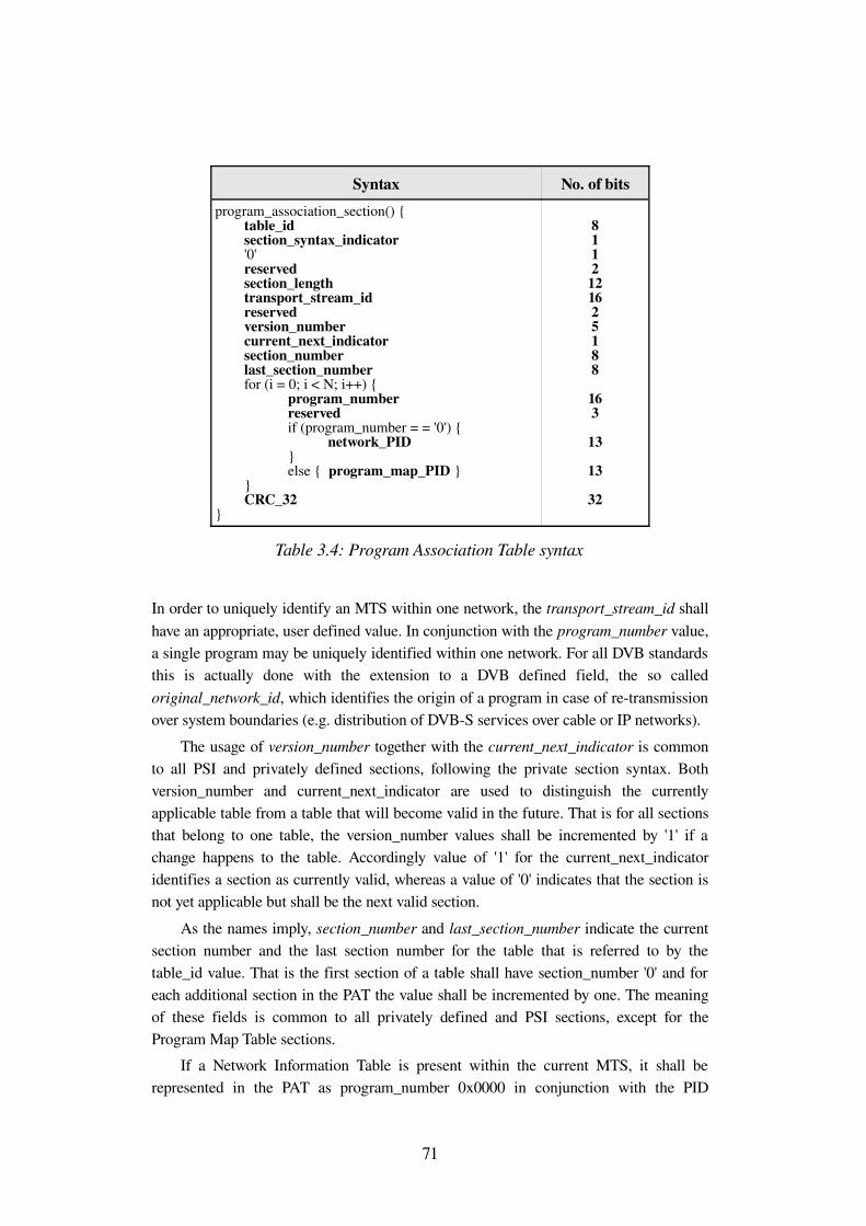
Syntax No. of bitsprogram_association_section() { table_id section_syntax_indicator '0' reserved section_length transport_stream_id reserved version_number current_next_indicator section_number last_section_number for (i = 0; i < N; i++) { program_number reserved if (program_number = = '0') { network_PID } else { program_map_PID } } CRC_32 }
8112121625188
163
13
13
32
Table 3.4: Program Association Table syntax
In order to uniquely identify an MTS within one network, the transport_stream_id shall have an appropriate, user defined value. In conjunction with the program_number value, a single program may be uniquely identified within one network. For all DVB standards this is actually done with the extension to a DVB defined field, the so called original_network_id, which identifies the origin of a program in case of retransmission over system boundaries (e.g. distribution of DVBS services over cable or IP networks).
The usage of version_number together with the current_next_indicator is common to all PSI and privately defined sections, following the private section syntax. Both version_number and current_next_indicator are used to distinguish the currently applicable table from a table that will become valid in the future. That is for all sections that belong to one table, the version_number values shall be incremented by '1' if a change happens to the table. Accordingly value of '1' for the current_next_indicator identifies a section as currently valid, whereas a value of '0' indicates that the section is not yet applicable but shall be the next valid section.
As the names imply, section_number and last_section_number indicate the current section number and the last section number for the table that is referred to by the table_id value. That is the first section of a table shall have section_number '0' and for each additional section in the PAT the value shall be incremented by one. The meaning of these fields is common to all privately defined and PSI sections, except for the Program Map Table sections.
If a Network Information Table is present within the current MTS, it shall be represented in the PAT as program_number 0x0000 in conjunction with the PID
71
reference network_PID. The network_PID shall take a user defined value within the range given in table 3.2.
All programs within the current MTS shall be represented in the PAT as a unique program_number (except 0x0000), together with the PID reference program_map_PID. Again, program_map_PID shall take a distinct value within the range given in table 3.2.
Summarizing the above observations, the PAT serves as an entry point for the discovery and selection of programs and services, that compose the current MTS. This main property makes the PAT a mandatory PSI table that must be included in every MTS. Properties of fields and flags within the PAT that are indicated to have a common behavior for other PSI or privately defined sections that follow the private section syntax, are omitted in the explanations on the remaining PSI types.
Program Map Table (PMT)
To allow for a mapping between a single program, its inherent elementary streams, the according PES types and the underlying time base, PSI defines the Program Map Table (PMT). PMT sections are defined to be carried in MTS packets within the PID range 0x0010 to 0xFFFE and to have a table_id value of 0x02. A target decoder determines the PID of the MTS packets that include one or more PMT sections that apply to the desired program_number, by inspecting the association given in the PAT.
Unlike other PSI tables, the PMT is allowed to use more than PID value for distinct PMT sections. In fact, this is implemented by current DVB applications as it reduces the processing effort for obtaining the desired PMT section.
PMT sections do not carry the transport_stream_id field (see table 3.4) as it is replaced by the program_number field, whose value corresponds to the associated program_number in the PAT. Hence, one PMT section only applies to one single program, which actually enables the use of only one PID for all PMT sections. A further particularity of the PMT is the meaning of the section_number and last_section_number field. Both fields shall carry the fixed value 0x00, which obviously disables the PMT to occupy more than one section for one single program.
As the MTS is designed to carry several programs with different time bases, it must provide a link to MTS packets carrying the timing information. This is achieved by the PCR_PID field within the PMT section. The PCR_PID points to MTS packets that carry the PCR values as part of their adaptation field (refer to subsection 3.3.1 MTS packet adaptation field). Note that only MTS packets with the PID values 0x0000, 0x0001 and 0x0010 to 0xFFFE are allowed to carry PCR values. In case of a television program, the PCR values are typically included in the MTS packets carrying the video PES. In case of a radio program, PCR values are necessary for a synchronized playback. Hence, if no PCR value is transmitted, the PCR_PID value shall take the value 0x1FFF.
72
The flexibility of the MTS multiplex to carry almost any data as payload must obviously be supplemented by appropriate description capabilities. The syntax elements explained so far basically cover properties of an MTS and its inherent programs that are assumed to be constant, also for future payload types. Considering for example the various characteristics of a television service, the limitation of the previous PSI syntax elements must be overcome. This is accomplished through the introduction of the descriptor mechanism. A descriptor is a syntactical subelement, which is typically defined for the purpose of one MTS program or program element property. Descriptors are identified by their 8bit descriptor_tag values and are selfcontained as they begin with this descriptor_tag, immediately followed by a descriptor_length field. As for the assignment of PID values, [35] provides a range of descriptor_tag values for user defined descriptors. Hence, the selfcontained property of descriptors enables MPEG2 compliant decoders to detect privately defined descriptors and discard them without any effects on the overall operation. Section 3.4 introduces the DVB defined descriptors that are important for the conversion of DVB Service Information into UPnP ContentDirectory Service.
Coming back to the explanation of the Program Map Table, the above PCR_PID field is followed by the program_info_length field that indicates the number of bytes of the descriptors that immediately follow this field. Possible descriptor candidates are the maximum_bitrate_descriptor and the copyright_descriptor. Both descriptors may either apply to a complete program or single program elements.
As descriptors that follow the program_info_length shall apply to the overall program, the PMT also offers the description of single program elements. A second loop lists all program elements (i.e. elementary streams), indicating the corresponding stream_type and PID value of the MTS packets that carry the elementary stream. In case of a television program, common stream types will likely be ISO/IEC 138182 Video and ISO/IEC 138183 Audio. Consequently a decoder will discover these elementary stream PIDs and start its decoding process. Optionally there may also be descriptors involved to describe single program elements. The number of bytes of all descriptors that apply to one elementary stream are given by the ES_info_length field. A typical candidate in case of an audio elementary stream is the ISO_639_language_descriptor that indicates the language of this program element.
Conditional Access Table (CAT)
The protection of content through Conditional Access (CA) mechanisms is one further important capability of today's digital broadcast standards. Enabling service providers to restrict the delivery of services to an authorized group of viewers, CA in MPEG2 systems typically employs two message types. An authorization check is performed by the CA decoder through the inspection of so called Entitlement Management Messages (EMM). Each EMM is uniquely encoded by an EMM generator, using a public key of the CA decoder. A subscriber management system maintains all public keys according
73
to the subscribed services. If a CA decoder detects its authorization, it will start to decode Entitlement Control Messages (ECM) that include a public key, called control word. The control word is finally combined with the CA decoder's private key to decode the scrambled elementary streams.
Through the use of the CA_descriptor, the CAT (PID = 0x0001, table_id = 0x01) associates one or more EMM and ECM streams with the PID of the MTS packets that carry these messages. If the CA_descriptor is found in the CAT, the associated EMM and ECM messages apply the the overall MTS. The CA_descriptor may also occur within the PMT as part of the program or elementary stream description. Accordingly the CA messages either apply to the program and all inherent program elements or to one single elementary stream.
The syntax of an EMM and ECM as payload of an MTS packet is user defined and depends on the employed CA system. The separation of several EMM and ECM streams as MTS packets with different PID values and thus the possibility to associate such streams to one single elementary video stream allows for the simultaneous use of more than one CA system for one MTS. This property fully meets the requirements of commercial service providers that typically prefer one single CA system.
In case of scrambled content, the DVBS UPnP AV MediaServer developed in this thesis assumes an appropriate CA decoder module. In absence of such decoder module, the DVBS UPnP AV MediaServer is able to omit scrambled services. Hence, the following discourse will not explain CA systems in greater detail.
Transport Stream Description Table (TSDT)
To indicate system wide properties that apply to the current MTS and all inherent programs and program elements respectively, the optional TSDT (PID = 0x0002, table_id = 0x03) may offer a list of appropriate descriptors for that purpose.
Private Table
To provide a template for privately defined tables, [35] introduces the private section syntax. The main purpose of this template is the transmission of private data with a minimum of structure that enables an MPEG2 compliant decoder to inspect such private section and to decide, whether it is able to decode it. In case the decoder decides to skip a private section, the private section syntax ensures that the decoder can accurately determine the length of this section and thus the decoder may directly access the next payload unit.
Sections following the private section syntax are allowed to be carried in MTS packets in the PID range from 0x0010 to 0xFFFE, while the table_id values intended for private sections range from 0x40 to 0xFE. It may not be surprising that DVB makes extensive use of the private section syntax to define DVB Service Information (DVBSI) tables (see section 3.4).
74
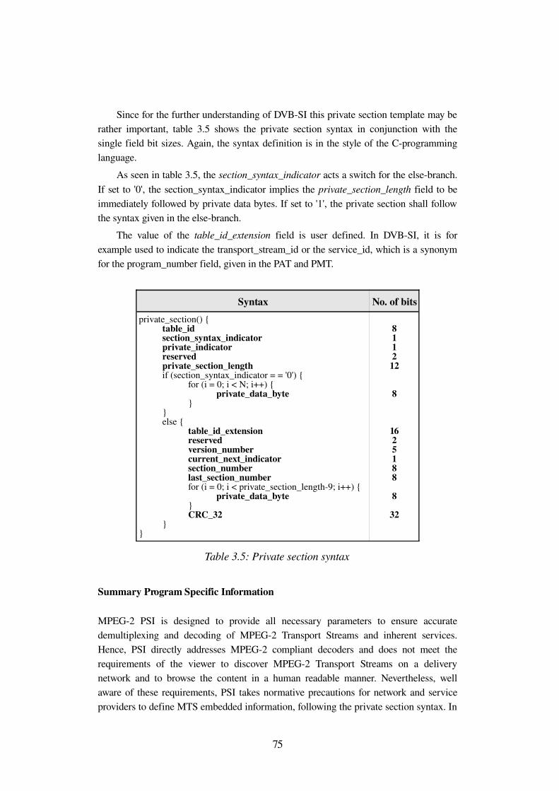
Since for the further understanding of DVBSI this private section template may be rather important, table 3.5 shows the private section syntax in conjunction with the single field bit sizes. Again, the syntax definition is in the style of the Cprogramming language.
As seen in table 3.5, the section_syntax_indicator acts a switch for the elsebranch. If set to '0', the section_syntax_indicator implies the private_section_length field to be immediately followed by private data bytes. If set to '1', the private section shall follow the syntax given in the elsebranch.
The value of the table_id_extension field is user defined. In DVBSI, it is for example used to indicate the transport_stream_id or the service_id, which is a synonym for the program_number field, given in the PAT and PMT.
Syntax No. of bitsprivate_section() { table_id section_syntax_indicator private_indicator reserved private_section_length if (section_syntax_indicator = = '0') { for (i = 0; i < N; i++) { private_data_byte } } else { table_id_extension reserved version_number current_next_indicator section_number last_section_number for (i = 0; i < private_section_length9; i++) { private_data_byte } CRC_32 } }
811212
8
1625188
8
32
Table 3.5: Private section syntax
Summary Program Specific Information
MPEG2 PSI is designed to provide all necessary parameters to ensure accurate demultiplexing and decoding of MPEG2 Transport Streams and inherent services. Hence, PSI directly addresses MPEG2 compliant decoders and does not meet the requirements of the viewer to discover MPEG2 Transport Streams on a delivery network and to browse the content in a human readable manner. Nevertheless, well aware of these requirements, PSI takes normative precautions for network and service providers to define MTS embedded information, following the private section syntax. In
75
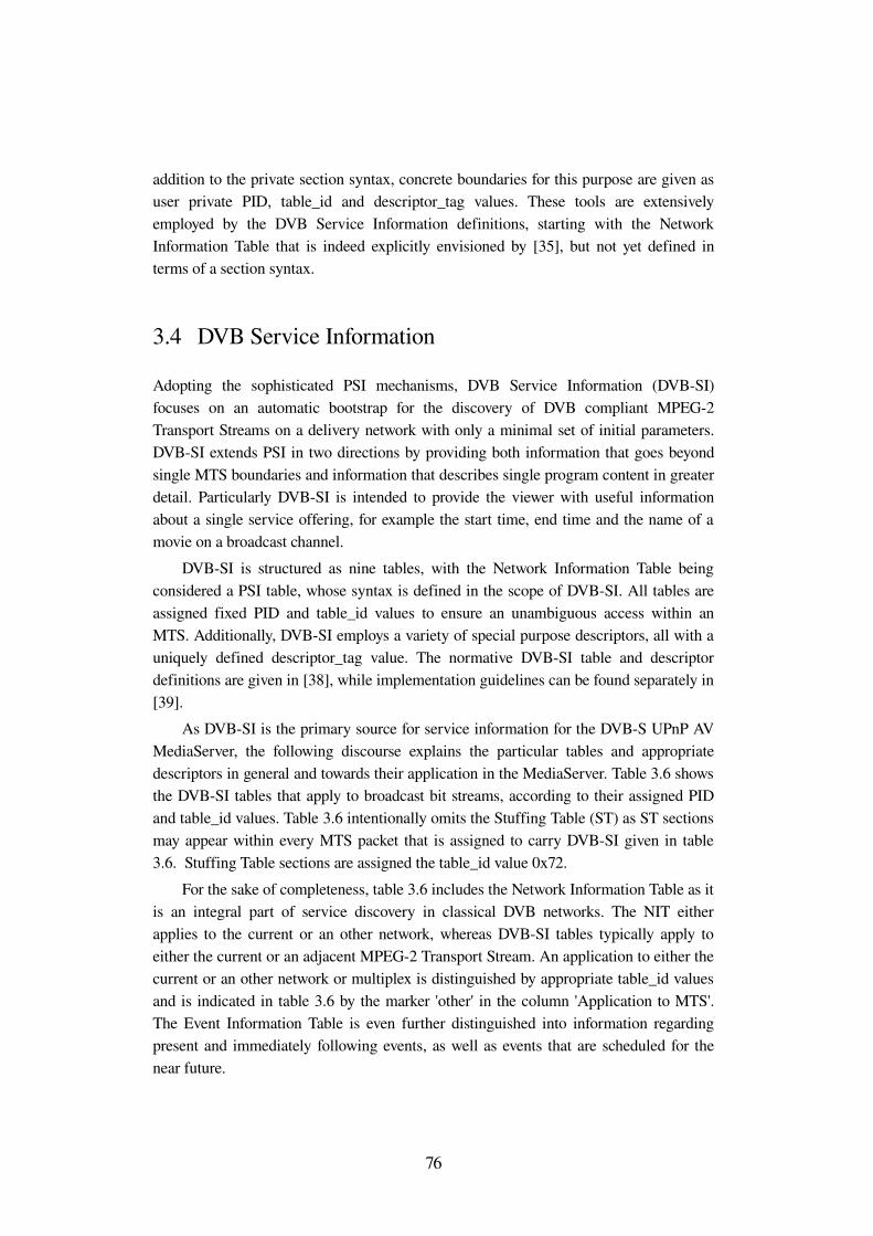
addition to the private section syntax, concrete boundaries for this purpose are given as user private PID, table_id and descriptor_tag values. These tools are extensively employed by the DVB Service Information definitions, starting with the Network Information Table that is indeed explicitly envisioned by [35], but not yet defined in terms of a section syntax.
3.4 DVB Service Information
Adopting the sophisticated PSI mechanisms, DVB Service Information (DVBSI) focuses on an automatic bootstrap for the discovery of DVB compliant MPEG2 Transport Streams on a delivery network with only a minimal set of initial parameters. DVBSI extends PSI in two directions by providing both information that goes beyond single MTS boundaries and information that describes single program content in greater detail. Particularly DVBSI is intended to provide the viewer with useful information about a single service offering, for example the start time, end time and the name of a movie on a broadcast channel.
DVBSI is structured as nine tables, with the Network Information Table being considered a PSI table, whose syntax is defined in the scope of DVBSI. All tables are assigned fixed PID and table_id values to ensure an unambiguous access within an MTS. Additionally, DVBSI employs a variety of special purpose descriptors, all with a uniquely defined descriptor_tag value. The normative DVBSI table and descriptor definitions are given in [38], while implementation guidelines can be found separately in [39].
As DVBSI is the primary source for service information for the DVBS UPnP AV MediaServer, the following discourse explains the particular tables and appropriate descriptors in general and towards their application in the MediaServer. Table 3.6 shows the DVBSI tables that apply to broadcast bit streams, according to their assigned PID and table_id values. Table 3.6 intentionally omits the Stuffing Table (ST) as ST sections may appear within every MTS packet that is assigned to carry DVBSI given in table 3.6. Stuffing Table sections are assigned the table_id value 0x72.
For the sake of completeness, table 3.6 includes the Network Information Table as it is an integral part of service discovery in classical DVB networks. The NIT either applies to the current or an other network, whereas DVBSI tables typically apply to either the current or an adjacent MPEG2 Transport Stream. An application to either the current or an other network or multiplex is distinguished by appropriate table_id values and is indicated in table 3.6 by the marker 'other' in the column 'Application to MTS'. The Event Information Table is even further distinguished into information regarding present and immediately following events, as well as events that are scheduled for the near future.
76
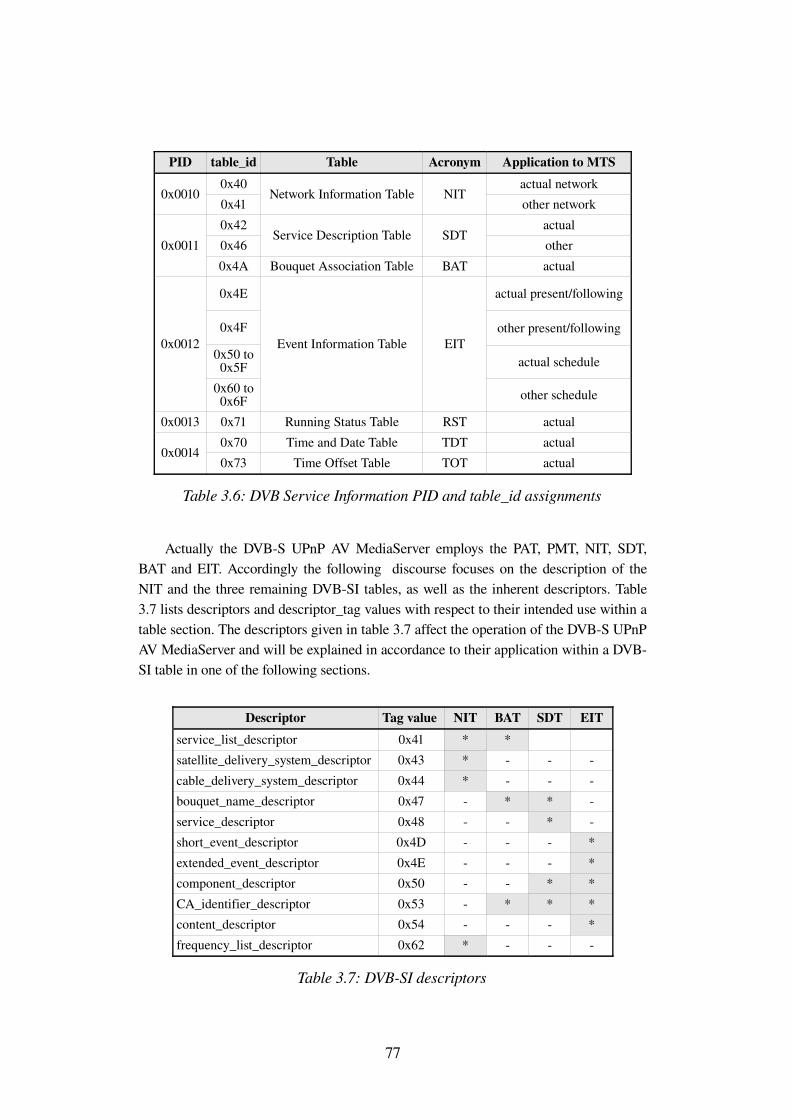
PID table_id Table Acronym Application to MTS
0x00100x400x41
Network Information Table NITactual networkother network
0x00110x420x46
Service Description Table SDTactualother
0x4A Bouquet Association Table BAT actual
0x0012
0x4E
0x4F
0x50 to 0x5F
0x60 to 0x6F
Event Information Table EIT
actual present/following
other present/following
actual schedule
other schedule
0x0013 0x71 Running Status Table RST actual
0x00140x70 Time and Date Table TDT actual0x73 Time Offset Table TOT actual
Table 3.6: DVB Service Information PID and table_id assignments
Actually the DVBS UPnP AV MediaServer employs the PAT, PMT, NIT, SDT, BAT and EIT. Accordingly the following discourse focuses on the description of the NIT and the three remaining DVBSI tables, as well as the inherent descriptors. Table 3.7 lists descriptors and descriptor_tag values with respect to their intended use within a table section. The descriptors given in table 3.7 affect the operation of the DVBS UPnP AV MediaServer and will be explained in accordance to their application within a DVBSI table in one of the following sections.
Descriptor Tag value NIT BAT SDT EITservice_list_descriptor 0x41 * *satellite_delivery_system_descriptor 0x43 * cable_delivery_system_descriptor 0x44 * bouquet_name_descriptor 0x47 * * service_descriptor 0x48 * short_event_descriptor 0x4D *extended_event_descriptor 0x4E *component_descriptor 0x50 * *CA_identifier_descriptor 0x53 * * *content_descriptor 0x54 *frequency_list_descriptor 0x62 *
Table 3.7: DVBSI descriptors
77
3.4.1 Network Information Table
As mandatory table for the actual MTS, the Network Information Table mainly provides a list of physical and logical parameters, necessary to tune to satellite transponders or cable/terrestrial channels that carry a multiprogram MTS. Information transmitted in NIT sections shall be stored in an Integrated Receiver Decoder (IRD) to allow for a fast transponder or channel switching. Hence, the NIT overcomes the timeconsuming channel search procedure in analogue broadcast networks because an initial set of parameters for one transponder or channel may be sufficient to discover all other multiplexes on a network.
In case of a satellite network, the satellite_delivery_system_descriptor conveys the physical and logical parameters to either tune DVBS or DVBS2 transponders. Only if DVBS2 is not used in a normative broadcast mode the satellite_delivery_system_descriptor must be supplemented by an appropriate DVBS2 delivery system descriptor. Section 3.2 (Modulation and Channel Coding) gave an introduction on the building blocks of a DVBS transmitter and thus the idea of what has to be adjusted in an IRD to setup the reception of a multiplex. Accordingly the satellite_delivery_system_descriptor carries the following fields.
● frequency (32 bits) As DVBS transmissions use frequencies from 10,7 GHz to 12,75 GHz with a typical channel bandwidth of 39,5 MHz, the frequency field gives eight 4bit Binary Coded Decimal (BCD) digits of the transponder center frequency, with the decimal point occurring after the third digit. That is, for the above DVBS frequency range the most significant four bits must encode the value zero and the subsequent eight bits encode a value between 10 and 12.
● orbital_position (16 bits) and west_east_flag (1 bit) The orbital position of geostationary satellites that provide DirectToHome digital television services is sufficiently described by the latitude and relative orientation towards the 0° Greenwich meridian. The most popular digital television satellites for Western Europe may be considered the SES Astra and Eutelsat Hotbird fleet, respectively consisting of several copositioned satellites at 19,2° East and 13° East. Hence, the orbital_position field encodes four BCD digits of the latitude, again with the decimal point after the third digit.
● polarization (2 bits) In order to reuse the existing frequency range, electromagnetic waves of nearly the same frequency are polarized orthogonal to each other, such that the available frequency band can virtually be doubled. The polarization field
78
encodes the four possible polarization types linearvertical, linearhorizontal, circularleft and circularright.
● modulation_system (1 bit) and modulation_type (2 bits) Section 3.2 introduces the Quaternary Phase Shift Keying (QPSK) as employed modulation scheme for DVBS transmissions. In addition to QPSK, DVBS2 may chose three further modulation schemes, namely 8PSK, 16APSK and 32APSK, with the two latter also modulating the amplitude of the resulting wave. The modulation_system flag distinguishes between DVBS and DVBS2 systems, with the modulation_type field indicating the only two concrete satellite modulation schemes, namely QPSK and 8PSK. Typically for DVBS systems, the modulation_type field takes the value '00', which requires an IRD to determine the scheme automatically.
● rolloff (2 bits) If the NIT section describes a DVBS2 modulation system, the rolloff field indicates the three possible rolloff factors of '0,20', '0,25' and '0,35'. As introduced in section 3.2, the rolloff factor denotes the signal spectrum shape and particularly the excess bandwidth over an ideal rectangular shape (rolloff factor zero). For DVBS the rolloff factor is fixed to '0,35' and thus the rolloff field shall take the fixed value of '00'. Regarding the smaller values for the DVBS2 system, obviously a better suppression of adjacent channel interference is achieved, which however requires better filter mechanisms for the baseband shaping process.
● symbol_rate (28 bits) The small rate of two bits per symbol for the QPSK modulation results in a high symbol rate of typically 22000 Msymbol/s and 27500 Msymbol/s. Accordingly the symbol_rate field encodes seven BCD digits of the employed symbol rate, again with the decimal point occurring after the third digit.
● FEC_inner (4 bits) The FEC_inner field gives the code rate of the inner coder of the DVBS and DVBS2 system. Due to the possible higher modulation schemes and resulting bit errors of a probably higher order in case of interference, the DVBS2 inner coding and puncturing may even produce a code rate of 1/4 (lowest code rate DVBS 1/2). On the other hand, the granularity for small redundancy is finer for DVBS2, as the highest code rate is 9/10 (highest code rate for DVBS 7/8). In DVBS systems this parameter is to be determined automatically by the IRD and consequently has no influence on the tuning procedure.
79
As the DVBS UPnP AV MediaServer assumes a fixed satellite dish (i.e. Astra 19,2° East) and as the name implies a DVBS system, the fields orbital_position, west_east_flag, rolloff, modulation_type and FEC_inner are omitted when inspecting the NIT, respectively the satellite_delivery_system_descriptor. However, the modulation_system flag is interpreted by means of an informative output to the user, if a DVBS2 transponder is detected. All other field values are stored within an appropriate dvb_frequency data structure to enable a fast channel switching as it is typical for a classical DVBS IRD. Consequently, the available DVBS services are stored with a pointer to the respective set of tuning parameters.
Due to the strong compliance with DVBC, the DVBS UPnP AV MediaServer also is able to address DVBC hardware and to interpret the according NIT descriptor, namely the cable_delivery_system_descriptor. Necessary parameters for tuning DVBC hardware are the frequency, the modulation scheme and the symbol rate. The employed dvb_frequency data structure for DVBS parameters is designed to also cover these DVBC parameters.
For either system, the DVBS UPnP AV MediaServer requires an initial set of tuning information for one single transponder or channel, in order to discover further multiplexes by inspecting the Network Information Table of the given MTS.
3.4.2 Service Description Table
While the PAT and PMT provide only basic service discovery information, the Service Description Table introduces several fields and descriptors that allow for a more comprehensive identification of for example the service type, its running status and underlying elementary stream types. Most important for the viewer may be the introduction of a textual identifier for a single service, in addition to the program number. In fact, the program number given in the PAT and PMT corresponds to the service_id field in the SDT to provide a direct association to services that are discovered through the use of PSI.
As entry point for the service scan procedure, the DVBS UPnP AV MediaServer inspects the SDT of each multiplex found within the NIT and extracts television and radio services that are currently running and either scrambled or unscrambled, depending on the presence of an appropriate CA module. This inspection requires the service_descriptor (see table 3.7) to be present, in order to determine the service provider name, service type and the service name, while the running status and CA mode are included in the SDT syntax. Service types that are currently supported by the DVBS UPnP AV MediaServer are listed in table 3.8, according to the service_type field value given in the service_descriptor. The text fields that represent the service provider and service name optionally include DVBSI control codes that are explained in detail in subsection 3.4.5. Furthermore the source encoding of DVBSI text fields does not match
80
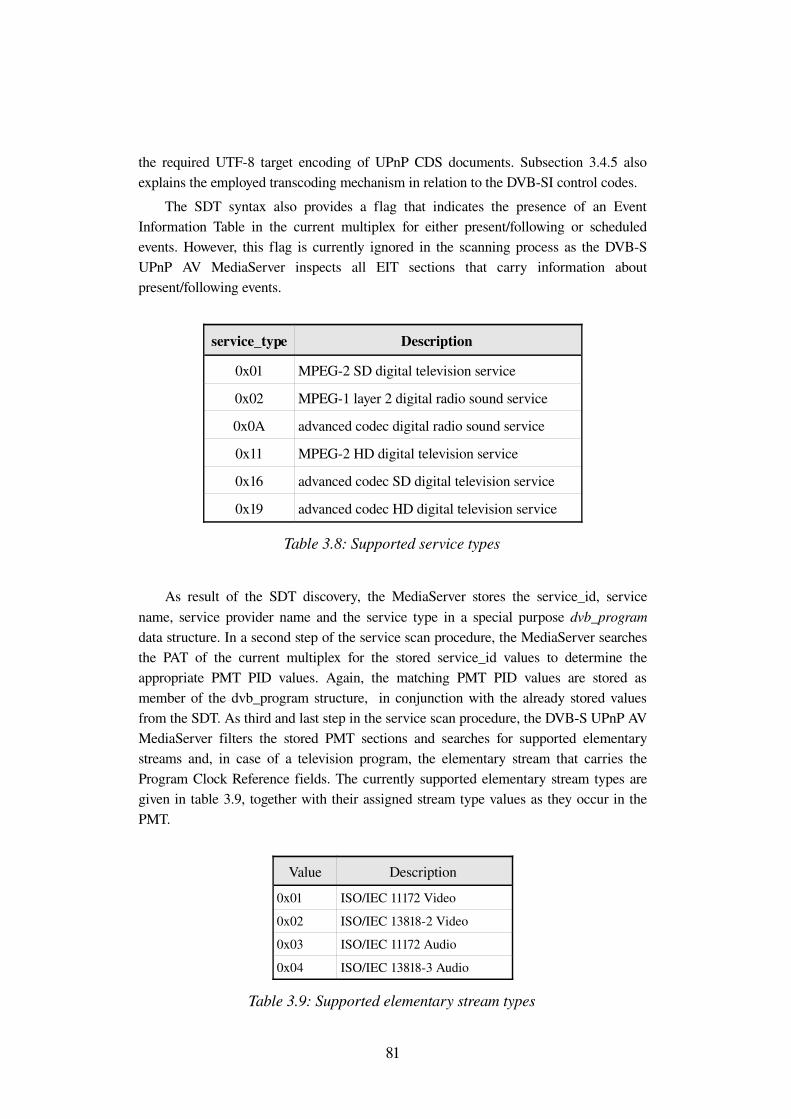
the required UTF8 target encoding of UPnP CDS documents. Subsection 3.4.5 also explains the employed transcoding mechanism in relation to the DVBSI control codes.
The SDT syntax also provides a flag that indicates the presence of an Event Information Table in the current multiplex for either present/following or scheduled events. However, this flag is currently ignored in the scanning process as the DVBS UPnP AV MediaServer inspects all EIT sections that carry information about present/following events.
service_type Description
0x01 MPEG2 SD digital television service
0x02 MPEG1 layer 2 digital radio sound service
0x0A advanced codec digital radio sound service
0x11 MPEG2 HD digital television service
0x16 advanced codec SD digital television service
0x19 advanced codec HD digital television service
Table 3.8: Supported service types
As result of the SDT discovery, the MediaServer stores the service_id, service name, service provider name and the service type in a special purpose dvb_program data structure. In a second step of the service scan procedure, the MediaServer searches the PAT of the current multiplex for the stored service_id values to determine the appropriate PMT PID values. Again, the matching PMT PID values are stored as member of the dvb_program structure, in conjunction with the already stored values from the SDT. As third and last step in the service scan procedure, the DVBS UPnP AV MediaServer filters the stored PMT sections and searches for supported elementary streams and, in case of a television program, the elementary stream that carries the Program Clock Reference fields. The currently supported elementary stream types are given in table 3.9, together with their assigned stream type values as they occur in the PMT.
Value Description
0x01 ISO/IEC 11172 Video
0x02 ISO/IEC 138182 Video
0x03 ISO/IEC 11172 Audio
0x04 ISO/IEC 138183 Audio
Table 3.9: Supported elementary stream types
81
As a reminder, the DVBS UPnP AV MediaServer performs an MPEG2 Transport Stream to MPEG2 Program Stream conversion. This decision is based on observations made with the primary target renderer Philips Streamium and the fact that other UPnP AV MediaRenderer devices are presumably designed to render file based content, which is typically not stored as MPEG2 Transport Stream. Consequently, all supported elementary streams (see table 3.9) are stored in a special purpose pes_pid data structure including the stream type, elementary PID and, if present, the language code. For each program, a variable pointer array as member of the respective dvb_program structure links to these pes_pid containers.
In case of a television program that includes one video and several audio streams, the single video stream is later combined with each audio stream in a way that such program appears as often in the UPnP ContentDirectory Service as there are different audio streams. This mechanism avoids a possible MediaRenderer disability to distinguish several audio streams in the transmitted MPEG2 Program Stream. The UPnP AV MediaServer represents such video and audio stream combination as instance of an object_id data structure that is later supplemented with the unique UPnP object_id value. Thus this association explicitly identifies one UPnP Broadcast item as a video and audio elementary stream tuple.
3.4.3 Event Information Table
An EIT section applies to a single DVB service and mainly distinguishes between information about the present and chronologically following event (EIT present/following) as well as events that are scheduled for the near future (EIT schedule). Similar to the Service Description Table, EIT sections may also carry event information for services of adjacent multiplexes. [39] subsection 4.4.1 defines the minimum repetition rate as two seconds for all EIT present/following sections in the current MTS on satellite and cable networks. Hence, during a time period of two seconds the DVBS UPnP AV MediaServer inspects all incoming EIT sections and associates the included information with the yet stored dvb_program instances, respectively the service_id of each program.
Per event, the EIT may include the short_event_descriptor and extended_event_descriptor, which carry the event name and a brief or detailed information about for example the topic of a documentary or the actors of a movie. The following listing introduces the fields that are included in an EIT section or event descriptor. Note that currently not all fields are interpreted by the DVBS UPnP AV MediaServer. However, preparations are made in terms of appropriate data structures that are yet capable of storing particular field information.
82
● EIT start_time (40 bits) This field encodes the start time of an event in two parts, beginning with 16 bits representing the 16 least significant bits of the Modified Julian Date (MJD), followed by 24 bits encoding the Coordinated Universal Time (UTC) as six BCD digits. The MJD bits encode the number of days that have elapsed since midnight at the beginning of November 17, 1858. As DVBSI wants to represent the time values relative to the year 1900, the formula (see [38] annex C) to calculate the concrete year, month and day values subtracts the approximately 41year offset in days from the value encoded in the 16 MJD bits. Both UTC and MJD time values have to be converted to match the constraints of the UPnP CDS time values that must be compliant to [40]. That is the start time of a service event shall appear in CDS XML documents as a string of the formYYYYMMDD'T'hh:mm:ss, for example "20070831T23:59:44".
● EIT duration (24 bits) Similar to the 24 UTC bits of the start_time field, the duration field also encodes six BCD digits, representing hours, minutes and seconds. Again, the duration value has to be converted to a string of the form "hh:mm:ss".
● short_event_descriptor – ISO_639_language_code (24 bits) In PSI and DVBSI, this field is used whenever a language is described. It encodes three 8bit letters indicating the language of a character string or elementary stream as defined by [41]. The reuse of this language in UPnP CDS requires no conversion, as the according XML element must be compliant to [42]. [42] chapter 2 defines a composite LanguageTag entity that consists of a Primarysubtag and optional subsequent Subtags. Section 2.2 of [42] specifies all 3letter subtags (either primary or subsequent) to be interpreted according to [41]. The employed character code table for the three letters is defined as ISO/IEC 88591 (see [38] annex A figure A.1).
● short_event_descriptor – event_name_length (8 bits) This field encodes the variable number of event_name_char bytes that include the actual event name and DVBSI control codes (see subsection 3.4.5 DVBSI character coding). Similar to the service provider and service name in the SDT, an interpretation of the DVBSI control codes and a transcoding into UTF8 has to be performed, before the event name is stored by the DVBS UPnP MediaServer.
83
● short_event_descriptor – text_length (8 bits) The text_length field encodes the number of text_char bytes that provide a short description for the currently inspected event. Again, the overall number of text_char bytes may include DVBSI control codes that have to be interpreted before the actual description can be stored.
● extended_event_descriptor – length_of_items (8 bits) Extended event information may be structured in two columns, with one column denoting an item and the second column an item description. The length_of_item field encodes the overall number of bytes for all item_char and item_description_char bytes, respectively including a length field for each group of character bytes that belongs to one item or item description. Similar to the above character strings, DVBSI control codes must be interpreted.
● extended_event_descriptor – text_length (8 bits) An extended_event_descriptor may also carry a nonitemized description according to the text_length field of the short_event_descriptor. The same rules for UTF8 conversion and control codes apply here.
● content_descriptor – content_nibble_level1 / content_nibble_level2 (4 bits each) Through the use of these two fields, the content_descriptor indicates the genre of the respective event. The level1 halfbyte distinguishes toplevel classification like Movie/Drama, Sports and Education/Science, whereas the level2 halfbyte constitutes a predefined element of one toplevel genre class. As an example for the Movie/Drama genre class, the level2 nibble may address a comedy or science fiction movie. Please refer to [38] table 28 for the full normative semantics of both fields.
The DVBS UPnP AV MediaServer currently stores the present and following event of a service, including the start time, duration, language, event name and short description as instances of the dvb_event data structure. The extended_event_descriptor is currently not interpreted but the dvb_event data structure already includes a placeholder for an extended event description string. When parsing the EIT, start time and duration of an event are immediately converted into a string that complies to [40] in order to simplify the later CDS XML document generation. Hence, the DVBS UPnP AV MediaServer associates the present and following event of a program with the particular dvb_program structure instance.
84
3.4.4 Bouquet Association Table
The BAT is the last of currently three DVBSI tables that are interpreted by the DVBS UPnP AV Media Server. Although the BAT is an optional DVBSI table, it is well adopted by DVB service and network providers to provide a reasonable distinction between services, relying on privately chosen criteria. A bouquet in DVBSI provides the possibility to present the viewer a virtual group of services that are combined using some representative bouquet name. Such bouquet name is included in the BAT as part of the bouquet_name_descriptor (see table 3.5) and may express service commonalities like the genre or the service provider. Similar to the variable length character strings within the SDT and EIT, the bouquet name field may include DVBSI control codes that have to be interpreted before a UTF8 encoding can be performed (see subsection 3.4.5).Nevertheless, a bouquet is not uniquely identified by its name, but by a 16bit bouquet_id value, taking the place of the table_id_extension field in the private section syntax (see table 3.5). Services that are included in one bouquet appear within the BAT as part of the service_list_descriptor (see table 3.7) that lists the service_id and service_type (see table 3.8) values. Hence, all services that appear in the BAT must be included in yet existing SDT and PAT/PMT sections to allow an IRD to uniquely associate a service_id found in the BAT with its service name and inherited elementary streams.
Note that this bouquet mechanism explicitly envisions the grouping of services from different multiplexes and even different networks by providing a field loop, with each loop pass including the transport_stream_id and original_network_id field. These two fields apply to one service_list_descriptor and by definition identify a DVB service globally. Consequently the BAT does not distinguish between the actual and adjacent multiplexes in terms of different table_id values.
The minimum repetition rate for all BAT sections is defined as ten seconds (see [39] subsection 4.4.1) for cable and satellite networks. Due to this relatively long period, the DVBS UPnP AV MediaServer optionally includes the BAT in its scanning process. The MediaServer provides a configuration file that controls the BAT scan by the value of the DISPLAY_BOUQUET flag. Each discovered DVB bouquet is stored as instance of the special purpose dvb_bouquet data structure, including the bouquet name, the number of services within the bouquet and a pointer array that provides a link to the appropriate dvb_program instances. Each dvb_bouquet instance is later supplemented by a unique UPnP object_id value, representing the DVB bouquet as UPnP container object. As mentioned in subsection 3.4.2, each dvb_program instance associates elementary streams of a single service with concrete UPnP Broadcast items, respectively the particular item object_id. Hence, through the linkage between a dvb_bouquet and dvb_program structure, the DVBS UPnP AV MediaServer is able to access the UPnP item representation of a DVB service with only one intermediary step.
85
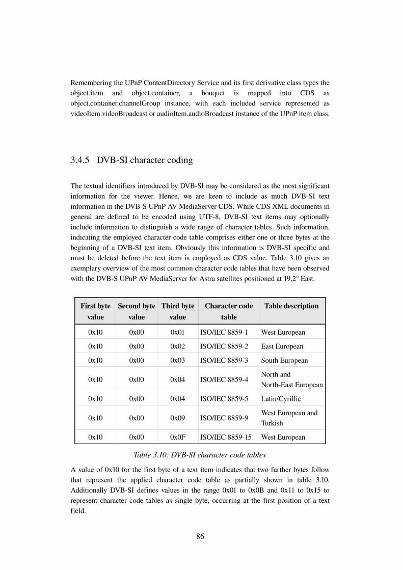
Remembering the UPnP ContentDirectory Service and its first derivative class types the object.item and object.container, a bouquet is mapped into CDS as object.container.channelGroup instance, with each included service represented as videoItem.videoBroadcast or audioItem.audioBroadcast instance of the UPnP item class.
3.4.5 DVBSI character coding
The textual identifiers introduced by DVBSI may be considered as the most significant information for the viewer. Hence, we are keen to include as much DVBSI text information in the DVBS UPnP AV MediaServer CDS. While CDS XML documents in general are defined to be encoded using UTF8, DVBSI text items may optionally include information to distinguish a wide range of character tables. Such information, indicating the employed character code table comprises either one or three bytes at the beginning of a DVBSI text item. Obviously this information is DVBSI specific and must be deleted before the text item is employed as CDS value. Table 3.10 gives an exemplary overview of the most common character code tables that have been observed with the DVBS UPnP AV MediaServer for Astra satellites positioned at 19,2° East.
First byte value
Second byte value
Third byte value
Character code table
Table description
0x10 0x00 0x01 ISO/IEC 88591 West European
0x10 0x00 0x02 ISO/IEC 88592 East European
0x10 0x00 0x03 ISO/IEC 88593 South European
0x10 0x00 0x04 ISO/IEC 88594North and NorthEast European
0x10 0x00 0x04 ISO/IEC 88595 Latin/Cyrillic
0x10 0x00 0x09 ISO/IEC 88599West European and Turkish
0x10 0x00 0x0F ISO/IEC 885915 West European
Table 3.10: DVBSI character code tables
A value of 0x10 for the first byte of a text item indicates that two further bytes follow that represent the applied character code table as partially shown in table 3.10. Additionally DVBSI defines values in the range 0x01 to 0x0B and 0x11 to 0x15 to represent character code tables as single byte, occurring at the first position of a text field.
86
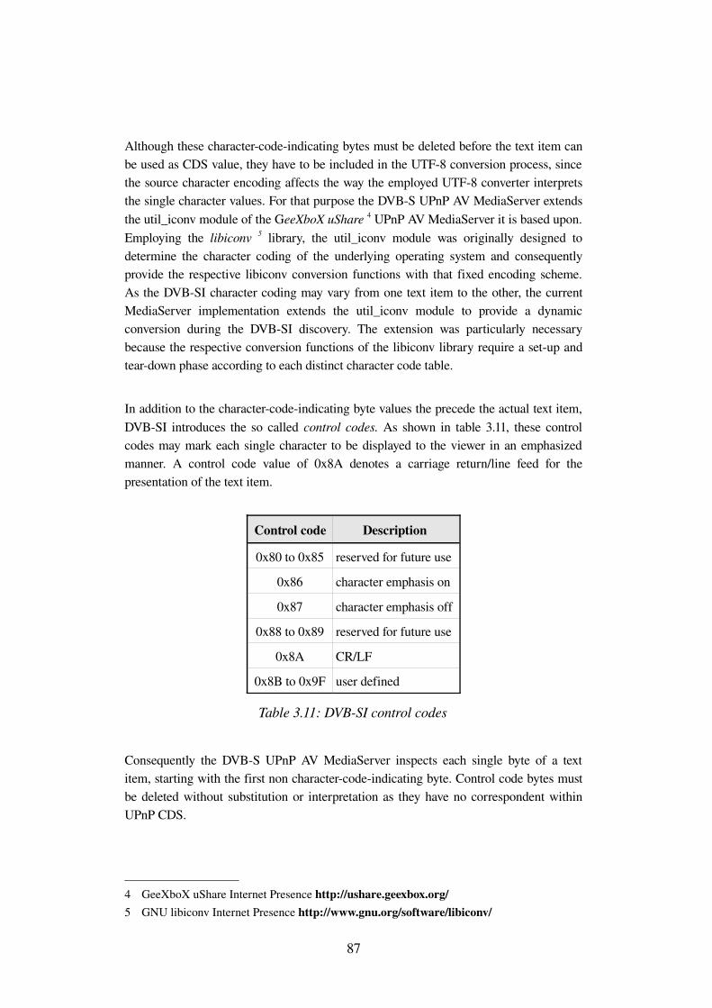
Although these charactercodeindicating bytes must be deleted before the text item can be used as CDS value, they have to be included in the UTF8 conversion process, since the source character encoding affects the way the employed UTF8 converter interprets the single character values. For that purpose the DVBS UPnP AV MediaServer extends the util_iconv module of the GeeXboX uShare 4 UPnP AV MediaServer it is based upon. Employing the libiconv 5 library, the util_iconv module was originally designed to determine the character coding of the underlying operating system and consequently provide the respective libiconv conversion functions with that fixed encoding scheme. As the DVBSI character coding may vary from one text item to the other, the current MediaServer implementation extends the util_iconv module to provide a dynamic conversion during the DVBSI discovery. The extension was particularly necessary because the respective conversion functions of the libiconv library require a setup and teardown phase according to each distinct character code table.
In addition to the charactercodeindicating byte values the precede the actual text item, DVBSI introduces the so called control codes. As shown in table 3.11, these control codes may mark each single character to be displayed to the viewer in an emphasized manner. A control code value of 0x8A denotes a carriage return/line feed for the presentation of the text item.
Control code Description
0x80 to 0x85 reserved for future use
0x86 character emphasis on
0x87 character emphasis off
0x88 to 0x89 reserved for future use
0x8A CR/LF
0x8B to 0x9F user defined
Table 3.11: DVBSI control codes
Consequently the DVBS UPnP AV MediaServer inspects each single byte of a text item, starting with the first non charactercodeindicating byte. Control code bytes must be deleted without substitution or interpretation as they have no correspondent within UPnP CDS.
4 GeeXboX uShare Internet Presence http://ushare.geexbox.org/5 GNU libiconv Internet Presence http://www.gnu.org/software/libiconv/
87
Finally, the DVBS UPnP AV MediaServer passes a version of the text item to the util_iconv module that is free of control codes and charactercodeindicating bytes. The UTF8 encoded result from the util_iconv module is then stored as part of an appropriate data structure within the MediaServer, in order to provide a fast access to these values in case of a Browse() or Search() request to the CDS. Potentially affected by this conversion are all DVBSI text items that have a variable length.
3.4.6 Summary DVBSI
Thinking of the UPnP and DVBIP approaches that extensively use XML to describe network and content properties, one can clearly notice that DVBSI is designed for networks where bandwidth and the unidirectional network structure are the major factors to be considered. Unlike XML, the DVBSI section syntax definitions include no tag overhead and does not envision compression techniques. The very lightweight design of DVBSI as derivative of MPEG2 PSI meets the high repetition rate of each table to obtain random access to a classical DVB network and its services.
The above subsections on the supported DVBSI tables already give some impressions on the implementation of storage data structures and conversion mechanisms within the DVBS UPnP AV MediaServer. Additionally some associations between DVBSI and UPnP CDS have been introduced. The concrete mapping in terms of a comparison of single CDS XML elements and attributes to DVBSI fields is given in the immediately following chapter 4.
88


4 Mapping DVBSI to UPnP CDS
4.1 Introduction
While DVBSI employs several tables to describe the properties of a single DVB service, the UPnP ContentDirectory Service represents a single piece of AV content as enclosed entity, namely a UPnP item. Consequently all information about available DVB services have to be collected before a concrete mapping to UPnP CDS items can be performed. Chapter 3 introduces the DVBSI tables and descriptors that are involved in the DVBS UPnP AV MediaServer service scan procedure. Chapter 3 also indicates the major data structures employed by the DVBS UPnP AV MediaServer to store DVBSI data.
The following sections discuss [1], which has been published by HUAWEI6 in the scope of the DVBIPI Technical Module, in order to propose a mapping from DVBSI to UPnP CDS. The analysis of [1] results into concrete implementation guidelines for the DVBS UPnP AV MediaServer. The discussion is supplemented by a review of the UPnP CDS XML properties that shall provide an essential insight into the target requirements, in contrast to the DVBSI characteristics.
Besides the propositions that refer to normative CDS elements, [1] also suggests semantical extensions to existing CDS properties and even introduces new CDS elements and attributes. Although we consider these extensions to be sophisticated, they are neither discussed nor implement due to the expected incompatibility with currently available Control Points.
4.2 The DIDLLite XML document
The UPnP ContentDirectory Service responds to Browse() and Search() requests with an XML document, encapsulated in the body of a SOAP message (see also section 1.2 clause control). The according XML document type is defined as DIDLLite7. DIDLLite has been derived from the Digital Item Declaration Language and is supplemented by UPnP specific elements and attributes to match the CDS requirements. Hence, DIDLLite documents represent the AV content of a UPnP MediaServer by providing nested CDS item and container objects. The evaluation of the a set of properties that are
6 HUAWEI Internet Presence http://www.huawei.com7 DIDLLite XSD Internet Presence http://www.upnp.org/schemas/av/didllitev2
20060531.xsd
90
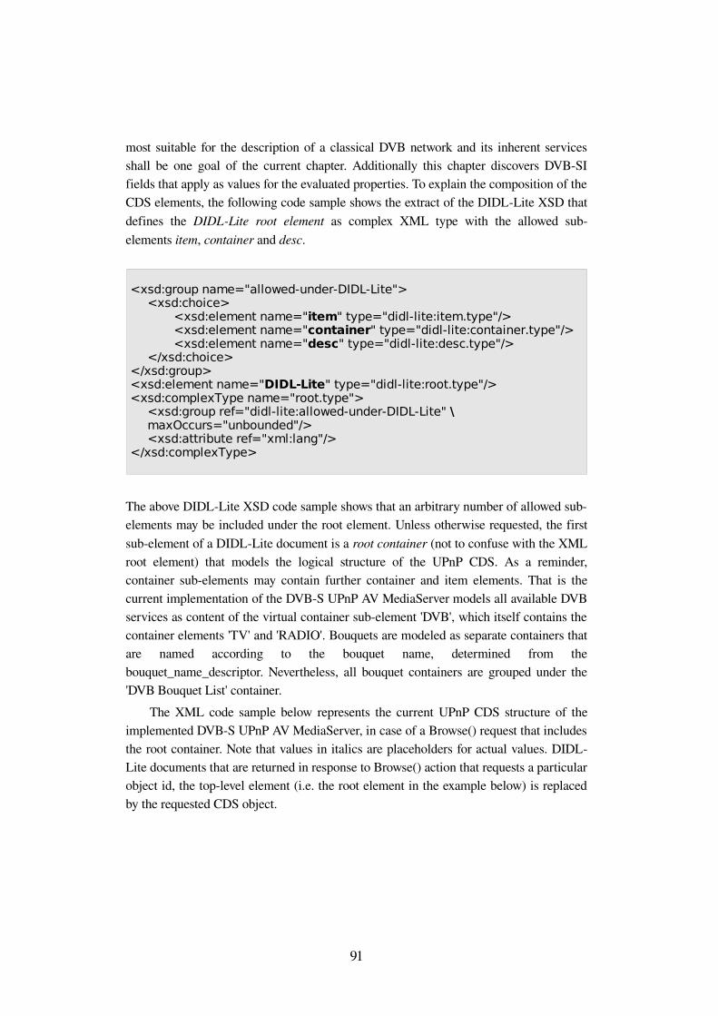
most suitable for the description of a classical DVB network and its inherent services shall be one goal of the current chapter. Additionally this chapter discovers DVBSI fields that apply as values for the evaluated properties. To explain the composition of the CDS elements, the following code sample shows the extract of the DIDLLite XSD that defines the DIDLLite root element as complex XML type with the allowed subelements item, container and desc.
The above DIDLLite XSD code sample shows that an arbitrary number of allowed subelements may be included under the root element. Unless otherwise requested, the first subelement of a DIDLLite document is a root container (not to confuse with the XML root element) that models the logical structure of the UPnP CDS. As a reminder, container subelements may contain further container and item elements. That is the current implementation of the DVBS UPnP AV MediaServer models all available DVB services as content of the virtual container subelement 'DVB', which itself contains the container elements 'TV' and 'RADIO'. Bouquets are modeled as separate containers that are named according to the bouquet name, determined from the bouquet_name_descriptor. Nevertheless, all bouquet containers are grouped under the 'DVB Bouquet List' container.
The XML code sample below represents the current UPnP CDS structure of the implemented DVBS UPnP AV MediaServer, in case of a Browse() request that includes the root container. Note that values in italics are placeholders for actual values. DIDLLite documents that are returned in response to Browse() action that requests a particular object id, the toplevel element (i.e. the root element in the example below) is replaced by the requested CDS object.
91
<xsd:group name="allowed-under-DIDL-Lite"><xsd:choice>
<xsd:element name="item" type="didl-lite:item.type"/><xsd:element name="container" type="didl-lite:container.type"/><xsd:element name="desc" type="didl-lite:desc.type"/>
</xsd:choice></xsd:group><xsd:element name="DIDL-Lite" type="didl-lite:root.type"/><xsd:complexType name="root.type">
<xsd:group ref="didl-lite:allowed-under-DIDL-Lite" \ maxOccurs="unbounded"/>
<xsd:attribute ref="xml:lang"/></xsd:complexType>
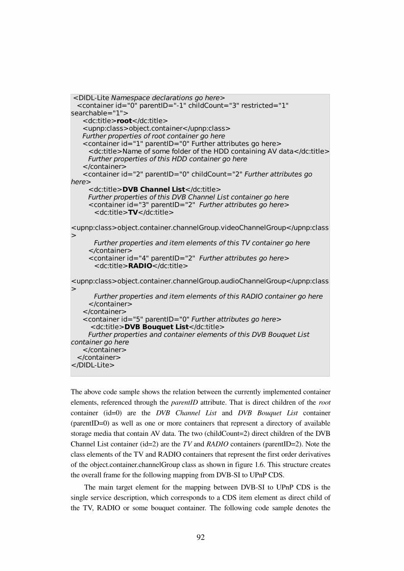
The above code sample shows the relation between the currently implemented container elements, referenced through the parentID attribute. That is direct children of the root container (id=0) are the DVB Channel List and DVB Bouquet List container (parentID=0) as well as one or more containers that represent a directory of available storage media that contain AV data. The two (childCount=2) direct children of the DVB Channel List container (id=2) are the TV and RADIO containers (parentID=2). Note the class elements of the TV and RADIO containers that represent the first order derivatives of the object.container.channelGroup class as shown in figure 1.6. This structure creates the overall frame for the following mapping from DVBSI to UPnP CDS.
The main target element for the mapping between DVBSI to UPnP CDS is the single service description, which corresponds to a CDS item element as direct child of the TV, RADIO or some bouquet container. The following code sample denotes the
92
<DIDL-Lite Namespace declarations go here><container id="0" parentID="-1" childCount="3" restricted="1"
searchable="1"><dc:title>root</dc:title><upnp:class>object.container</upnp:class>Further properties of root container go here
<container id="1" parentID="0" Further attributes go here> <dc:title>Name of some folder of the HDD containing AV data</dc:title>
Further properties of this HDD container go here </container><container id="2" parentID="0" childCount="2" Further attributes go
here><dc:title>DVB Channel List</dc:title>Further properties of this DVB Channel List container go here <container id="3" parentID="2" Further attributes go here>
<dc:title>TV</dc:title>
<upnp:class>object.container.channelGroup.videoChannelGroup</upnp:class>
Further properties and item elements of this TV container go here </container><container id="4" parentID="2" Further attributes go here>
<dc:title>RADIO</dc:title>
<upnp:class>object.container.channelGroup.audioChannelGroup</upnp:class>
Further properties and item elements of this RADIO container go here </container>
</container> <container id="5" parentID="0" Further attributes go here>
<dc:title>DVB Bouquet List</dc:title> Further properties and container elements of this DVB Bouquet List container go here
</container></container>
</DIDL-Lite>
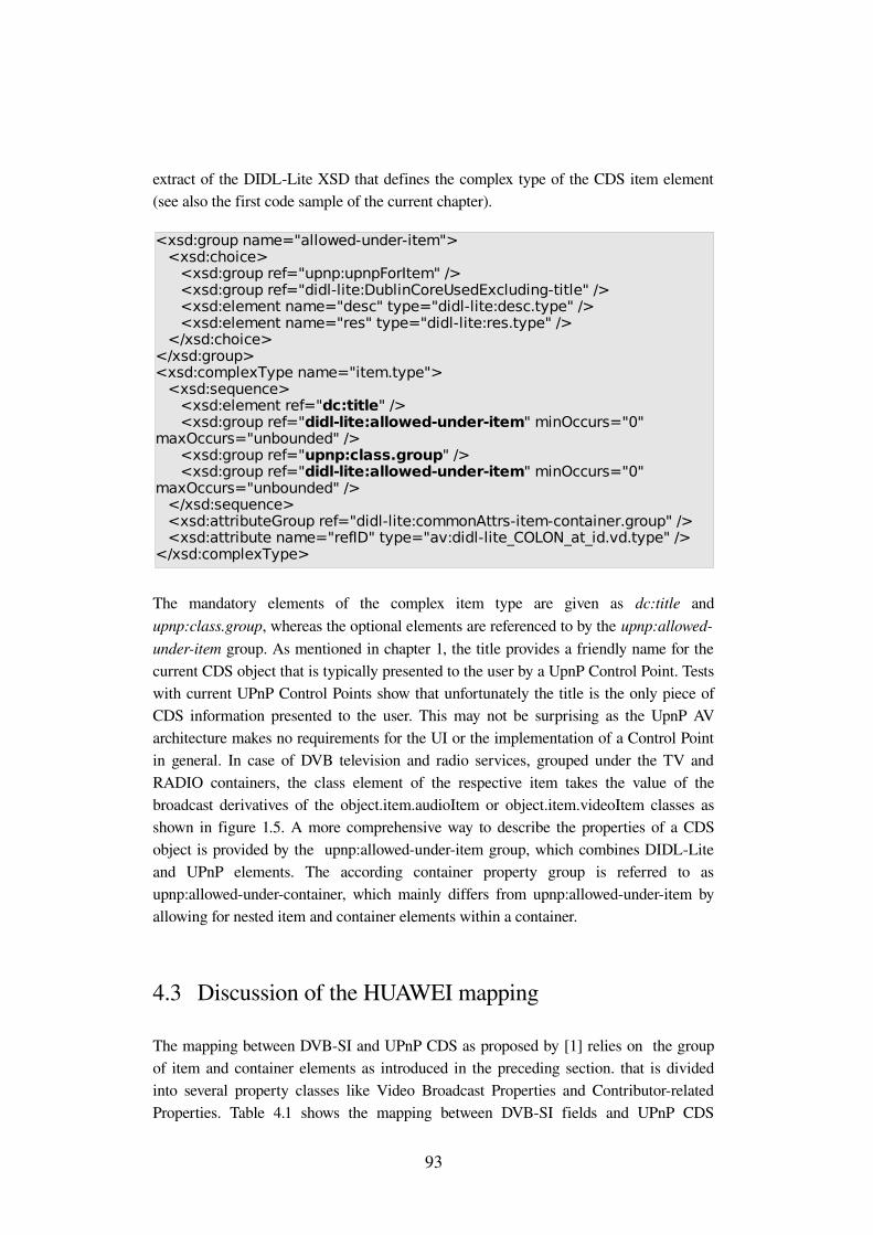
extract of the DIDLLite XSD that defines the complex type of the CDS item element (see also the first code sample of the current chapter).
The mandatory elements of the complex item type are given as dc:title and upnp:class.group, whereas the optional elements are referenced to by the upnp:allowedunderitem group. As mentioned in chapter 1, the title provides a friendly name for the current CDS object that is typically presented to the user by a UpnP Control Point. Tests with current UPnP Control Points show that unfortunately the title is the only piece of CDS information presented to the user. This may not be surprising as the UpnP AV architecture makes no requirements for the UI or the implementation of a Control Point in general. In case of DVB television and radio services, grouped under the TV and RADIO containers, the class element of the respective item takes the value of the broadcast derivatives of the object.item.audioItem or object.item.videoItem classes as shown in figure 1.5. A more comprehensive way to describe the properties of a CDS object is provided by the upnp:allowedunderitem group, which combines DIDLLite and UPnP elements. The according container property group is referred to as upnp:allowedundercontainer, which mainly differs from upnp:allowedunderitem by allowing for nested item and container elements within a container.
4.3 Discussion of the HUAWEI mapping
The mapping between DVBSI and UPnP CDS as proposed by [1] relies on the group of item and container elements as introduced in the preceding section. that is divided into several property classes like Video Broadcast Properties and Contributorrelated Properties. Table 4.1 shows the mapping between DVBSI fields and UPnP CDS
93
<xsd:group name="allowed-under-item"><xsd:choice>
<xsd:group ref="upnp:upnpForItem" /> <xsd:group ref="didl-lite:DublinCoreUsedExcluding-title" /> <xsd:element name="desc" type="didl-lite:desc.type" /> <xsd:element name="res" type="didl-lite:res.type" />
</xsd:choice></xsd:group><xsd:complexType name="item.type">
<xsd:sequence><xsd:element ref="dc:title" /> <xsd:group ref="didl-lite:allowed-under-item" minOccurs="0"
maxOccurs="unbounded" /> <xsd:group ref="upnp:class.group" /> <xsd:group ref="didl-lite:allowed-under-item" minOccurs="0"
maxOccurs="unbounded" /> </xsd:sequence><xsd:attributeGroup ref="didl-lite:commonAttrs-item-container.group" /> <xsd:attribute name="refID" type="av:didl-lite_COLON_at_id.vd.type" />
</xsd:complexType>
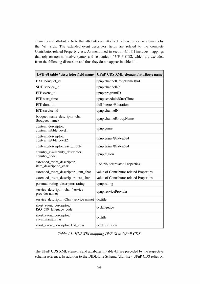
elements and attributes. Note that attributes are attached to their respective elements by the ‘@’ sign. The extended_event_descriptor fields are related to the complete Contributorrelated Property class. As mentioned in section 4.1, [1] includes mappings that rely on nonnormative syntax and semantics of UPnP CDS, which are excluded from the following discussion and thus they do not appear in table 4.1.
DVBSI table / descriptor field name UPnP CDS XML element / attribute nameBAT: bouquet_id upnp:channelGroupName@idSDT: service_id upnp:channelNrEIT: event_id upnp:programIDEIT: start_time upnp:scheduledStartTimeEIT: duration didllite:res@durationEIT: service_id upnp:channelNrbouquet_name_descriptor: char (bouquet name) upnp:channelGroupName
content_descriptor: content_nibble_level1 upnp:genre
content_descriptor: content_nibble_level2 upnp:genre@extended
content_descriptor: user_nibble upnp:genre@extendedcountry_availability_descriptor: country_code upnp:region
extended_event_descriptor: item_description_char Contributorrelated Properties
extended_event_descriptor: item_char value of Contributorrelated Propertiesextended_event_descriptor: text_char value of Contributorrelated Propertiesparental_rating_descriptor: rating upnp:ratingservice_descriptor: char (service provider name) upnp:serviceProvider
service_descriptor: Char (service name) dc:title short_event_descriptor: ISO_639_language_code dc:language
short_event_descriptor: event_name_char dc:title
short_event_descriptor: text_char dc:description
Table 4.1: HUAWEI mapping DVBSI to UPnP CDS
The UPnP CDS XML elements and attributes in table 4.1 are preceded by the respective schema reference. In addition to the DIDLLite Schema (didllite), UPnP CDS relies on
94
the Simple Dublin Core XML Schema8 (dc) and UPnP XML Schema9 (upnp). In reference to table 4.1, the following discourse explains the single mappings in greater detail with respect to conversion characteristics and the DVBS UPnP AV MediaServer internal data types. Note that not all mappings are currently implemented due to logical differences.
BAT: bouquet_id – upnp:channelGroupName@id
Within the BAT, the bouquet_id is a 16bit field whose integer value distinguishes the actual bouquet uniquely from other bouquets on the current network. [1] section 1.2 wrongly makes the proposal for the direct mapping from the bouquet_id to id attribute. The id attribute as part of upnp:channelGroupName element is defined as string value of the format '<ICANN registered domain> "_" <channel group id defined in the domain>'. Obviously this format is not met by the bouquet_id field and can not be derived from other DVBSI fields. Thus this mapping represents a nonnormative application of the id attribute. As the id attribute is required for the occurrence of the upnp:channelGroupName element and its employment is desirable for bouquet containers, the DVBS UPnP AV MediaServer implements but disables this mapping. In terms of a vendor specific XSD, this mapping could easily be adopted by defining an appropriate XML element type that includes a numerical id attribute.
SDT: service_id – upnp:channelNr
The SDT section syntax defines the service_id as 16bit integer field that identifies a service from any other in the scope of one MTS. [1] section 1.3 wrongly maps the service_id field to the upnp:channelNr element, which is only defined in conjunction with the upnp:channelID element and its type attribute. [12] annex B.11.1 defines the upnp:channelNr to be set equal to the major channel number of the upnp:channelID with its type attribute set to the value 'DIGITAL'. For DVB systems this relation is obviously represented by the MPEG2 Transport Stream id value that corresponds to the addressed major channel number and the respective service_id value that matches the upnp:channelID element.
At this point the possibly misleading terminology of the CDS property classes must be mentioned. The upnp:channelNr belongs to the Video Broadcast Property class, whereas the upnp:channelID is part of the Recorded Objectrelated Property class. Regarding the description of one piece of AV content, the terms broadcast and recorded may be considered controversial. Nevertheless, [12] annex B.8.5 allows the upnp:channelID element to describe items that represent a tuner channel that
8 Simple Dublin Core XSD Internet Presence http://dublincore.org/schemas/xmls/simpledc20021212.xsd
9 UPnP XSD Internet Presence http://www.upnp.org/schemas/av/upnpv220060531.xsd
95
consequently is a broadcast channel. The DVBS UPnP AV MediaServer implements both elements with the upnp:channelID@type attribute set to the fixed value 'DIGITAL'.
SDT: transport_stream_id – upnp:channelNr
Similar to the preceding DVBSI fields, the transport_stream_id comprises 16 bits and identifies an MTS uniquely in conjunction with the original network id. The necessity of this mapping to the upnp:channelNr element is explained the above clause. The data formats of both transport_stream_id and upnp:channelNr are defined as integer values and thus they can be adopted without conversion. Note that this mapping is not included in [1], which in section 1.1 classifies the employment of the transport_stream_id field within UPnP CDS as needless.
EIT: event_id – upnp:programID
In order to distinguish events in the scope of a DVB service, the EIT section syntax defines the 16bit event_id field to represent an integer value. The upnp:programID element is defined to provide a set of parameters that allow for an unambiguous recording of the item it describes.
Again, [1] section 1.4 spuriously states this direct mapping that can not be performed because of the particular format constraints for the upnp:programID element. [12] annex B.8.3 defines the format and semantics of the upnp:programID element to follow the srs:matchedID property as given in [17] annex B.13.2. The UPnP ScheduledRecording Service definition recursively relates the srs:matchedID element to the format of the srs:matchingID property (see [17] annex B.5.2), which also includes a type attribute that acts a switch for the syntax and semantics of the concrete element value. In case of a DVB service, we consider a type value of 'SI_PROGRAMID' as most appropriate. This choice implies a value string of the following format '<Network ID>","<Transport Stream ID>","<Service ID>","<Program ID>'. Remembering chapter 3, one can immediately recognize direct analogies to DVBSI fields that are even similarly named. Hence the proposal made in [1] for the direct mapping must be extended to the DVBSI fields original_network_id, transport_stream_id and service_id, with the event_id field corresponding to the <Program ID> substring of the upnp:programID element value.
The additional three field values can and actually are retrieved from the respective EIT section. The DVBS UPnP AV MediaServer implements this extended mapping, which in some way denotes a redundancy to the above mappings to the upnp:channelID and upnp:channelNr elements that already represent the service_id and transport_stream_id fields in the scope of UPnP CDS.
96
EIT: start_time – upnp:scheduledStartTime
As introduced in subsection 3.4.3, the 40bit start_time field encodes a date and time value that has to be converted to match the format of the upnp:scheduledStartTime element. The DVBS UPnP AV MediaServer implements this conversion by means of the functions mjd_convert() and utc_convert() that convert the date and time bits to an appropriate character string while parsing an EIT section. The resulting character strings are concatenated and stored as start element of the special purpose dvb_event data structure within the MediaServer.
EIT: duration – didllite:res@duration
Again, section 3.4.3 introduced the coding of the 24bit duration field, which is converted with the utc_convert() function of the DVBS UPnP AV MediaServer to match the format 'hh:mm:ss' that is required by duration attribute of the res element. Note that not necessarily the hour must be doubledigit. The resulting character string is stored as duration element of the dvb_event data structure to enable the dynamic generation of DIDLLite documents, if requested by a UPnP Control Point.
EIT: service_id – upnp:channelNr
EIT sections directly refer to one DVB service through the value of the service_id field. The service_id field size and value is equal to that in the respective SDT section. The above clause on the mapping of the SDT: service_id field already states the direct relation of the SDT:service_id field to the upnp:channelNr element as invalid. Due to the identical semantics of the service_id field within EIT and SDT, the statement made for the SDT: service_id field also applies to the EIT: service_id field. Consequently we classify the direct mapping of EIT: service_id to upnp:channelNr as given in [1] section 1.4 to be invalid as well. Regardless of this observation, the DVBS UPnP AV MediaServer utilizes the EIT: service_id field only for the discovery of EIT information that matches DVB services, which have been discovered earlier through the inspection of the Service Description Table. Hence, the service_id value is already stored in conjunction with other service information when accessing the EIT.
bouquet_name_descriptor: char (bouquet name) – upnp:channelGroupName
As mentioned in the first clause that attends the BAT: bouquet_id field, the mapping of bouquet name to the upnp:channelGroupName fails due to the format of the required id attribute. The implementation of the DVBS UPnP AV MediaServer avoids this incompatibility by mapping the bouquet name to the dc:title element of the respective
97
CDS bouquet containers. Since the dc:title element is mandatory for each CDS item and container, the upnp:channelGroupName element, if present, would add redundancy to the described CDS bouquet container, because we can not find any other reasonable value for dc:title and upnp:channelGroupName than the actual bouquet name. The conversion of the DVBSI character string includes the interpretation and deletion of DVB control codes, as well as the encoding of the character string into UTF8 (see subsection 3.4.5). Hence the bouquet name is stored within the MediaServer as name element of the special purpose dvb_bouquet data structure, which maintains a link to each included DVB service in terms of a pointer to the respective dvb_program data structure.
[1] section 2.2 makes the proposition to extent the upnp:channelGroupName as mulivalued property to enable the mapping between bouquet name and upnp:channelGroupName. That is a multivalued property may occur more than once within a CDS element. This proposition is made without further explanation but we assume the intention to reproduce the occurrence of the bouquet_name_descriptor within the SDT for CDS items. Although the UPnP and DIDLLite Schema definitions allow for the occurrence of the upnp:channelGroupName as part of a CDS item, [12] annex B.9.1 defines the upnp:channelGroupName as property of a channelGroup, which is a first order derivative of the CDS object.container class. Hence the extension to a multivalued property and application to a CDS item instead of a container object would still conflict with the normative semantics of the upnp:channelGroupName.
content_descriptor: content_nibble_level1 – upnp:genre
Genre information about a given event is provided via two halfbytes, namely the content_nibble_level1 and content_nibble_level2 of the content_descriptor. Both nibbles encode an integer value that indicates the genre of an event through a DVBSI lookup table. The type of the upnp:genre element is defined as string value that indicates the genre to which a CDS object belongs. Since upnp:genre is multivalued it may also apply to a CDS container. [1] section 2.4 suggests this mapping, which obviously requires the implementation of the DVBSI lookup table. For that purpose, the DVBS UPnP AV MediaServer avails itself of the appropriate dvbstrContentNibble_TYPE() function from the employed DVB Stream Analyzer dvbsnoop10 that takes both nibbles as input and returns a character string according to [38] table 28. This choice extends the proposal of [1] to the content_nibble_level2, which is absolutely covered by the semantics of the upnp:genre element, as defined in [12] annex B.4.1. Furthermore the choice to include the content_nibble_level2 in the mapping to the upnp:genre element avoids an incompatibility within the suggestion made by [1] for the mapping between content_nibble_level2 and the upnp:genre@extended attribute. This erroneous mapping is discussed in the following clause.
10 dvbsnoop Internet Presence http://dvbsnoop.sourceforge.net/
98
content_descriptor: content_nibble_level2 – upnp:genre@extended
The preceding clause introduces the current application of the content_nibble_level2 halfbyte to the CDS of the DVBS UPnP AV MediaServer. For the sake of completeness, the mapping between content_nibble_level2 and the upnp:genre@extended attribute, as proposed in [1] section 2.4, is discussed here. The complex type of the upnp:genre element is given in the UPnP XSD [19] as genre.type, which defines both extended and id attributes as optional.
Even if we assume a pure orientation at the CDS Schema definitions, this mapping still violates the fact that the upnp:genre@extended attribute value must comply with the csv.1_.string.len.1_ simple type as defined in the AV XSD11. The csv.1_.string.len.1_ type requires a Comma Separated Value (CSV) list of at least two values (excluding the comma as part of the value string), separated by commas. The syntactical requirement for at least two values is supplemented by the semantical definitions made in [12] annex B.4.1.2 that appoint the first value of the CSV list to the actual value of the upnp:genre element. Further comma separated values shall represent increasingly precise names of applicable subgenres.
The preceding clause sets the upnp:genre value to the string that corresponds to the content_nibble_level1 value. Hence the second value of the CSV list could theoretically be set to the value that complies with the content_nibble_level2 value. Practically the employment of the upnp:genre@extended attribute entails the requirement of the upnp:genre@id attribute as defined in [12] annex B.4.1.1. Finally, the required format of the upnp:genre@id attribute disables the employment of the upnp:genre@extended attribute, as it includes an ICANN12 registered domain and some privately defined genre_scheme_id. Such values can not be derived from DVB Service Information.
content_descriptor: user_nibble – upnp:genre@extended
The content_descriptor includes two user_nibble halfbytes, the semantics of which is defined by the broadcaster. Disregarding the still necessary but not deducible upnp:genre@id attribute, the inclusion of the user_nibble fields might be useful, unless the semantics are well known to the DVBS UPnP AV MediaServer. Nevertheless, we consider the knowledge of such privately defined semantics in advance as not feasible and thus we ignore this proposition.
country_availability_descriptor: country_code – upnp:region
Depending on the country_availability_flag, one or more 24bit country_code values either specify the availability or unavailability of a DVB service. That is the country_code field either represents three 8bit letters or digits, encoded in compliance
11 AV XSD Internet Presence http://www.upnp.org/schemas/av/avv120060531.xsd12 Internet Corporation for Assigned Names and Numbers Internet Presence
http://www.icann.org/
99
with ISO/IEC 88591. In case of three letters, the value shall denote a country code as defined in [43]. If the value represents a number in the range 900 to 999, country_code specifies an ETSI defined group of countries as allocated in [44].
The meaning of the upnp:region element differs from the country_code field. The upnp:region property shall identify a region that is associated with the source of an object. Such identification shall be accomplished by a character string that may for example state the country or city, a single piece of AV content originates from. Considering this varying intent of both country_code and upnp:region, we additionally estimate the practical use of a country_code equivalent within CDS as marginal. Thus the implementation of the DVBS UPnP AV MediaServer omits this proposition as made by [1] section 2.6.
extended_event_descriptor: item_description_char Contributorrelated Properties
Subsection 3.4.3 introduces the syntax and semantics of the extended_event_descriptor, which is capable of describing an event in terms of a twocolumn listing that may include for example a comparison of the character names of a movie with the actual actor names. Regarding this example, a single character name is referred to as item description, whereas an actor name denotes an item. The extended_event_descriptor organizes item_description/item pairs in a loop. Again, regarding the character name/actor name example, one loop pass includes the two fields item_description_length and item_length that give the number of bytes that represent a character name (item description) and actor name (item). [1] section 2.7 relates the string value that is represented by the number of item_description_char bytes per loop pass to one of the UPnP CDS Contributorrelated Properties (see [12] annex B.3). These properties comprise the elements upnp:artist, upnp:actor, upnp:author, upnp:producer, upnp:director, dc:publisher and dc:contributor, with artist, actor and author having an additional role attribute. Considering especially the upnp:actor and upnp:actor@role properties, we must admit that the above character name/actor name example has been intentionally chosen.
Focusing now on a concrete mapping approach, the weakness of the suggestion made by [1] section 2.7 should quickly become clear. As neither the item description, nor the item itself is categorized in a way that announces the type of textual information it represents, a module that parses such character strings would have to perform a search for substrings that match one of the Contributorrelated Property names. A search for substring obviously requires one or more item description/item pairs to represent a title for subsequent pairs, which is not stipulated by DVBSI. Furthermore the CDS elements in question only cover a small area of the overall capabilities of the item description and item elements of the extended_event_descriptor. Consequently we consider a mapping from an item description to one of the seven Contributorrelated Properties (not to confuse with the property values) as practically not realizable.
100
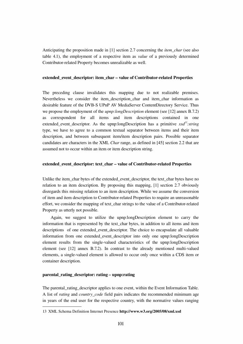
Anticipating the proposition made in [1] section 2.7 concerning the item_char (see also table 4.1), the employment of a respective item as value of a previously determined Contributorrelated Property becomes unrealizable as well.
extended_event_descriptor: item_char – value of Contributorrelated Properties
The preceding clause invalidates this mapping due to not realizable premises. Nevertheless we consider the item_description_char and item_char information as desirable feature of the DVBS UPnP AV MediaServer ContentDirectory Service. Thus we propose the employment of the upnp:longDescription element (see [12] annex B.7.2) as correspondent for all items and item descriptions contained in one extended_event_descriptor. As the upnp:longDescription has a primitive xsd13:string type, we have to agree to a common textual separator between items and their item description, and between subsequent item/item description pairs. Possible separator candidates are characters in the XML Char range, as defined in [45] section 2.2 that are assumed not to occur within an item or item description string.
extended_event_descriptor: text_char – value of Contributorrelated Properties
Unlike the item_char bytes of the extended_event_descriptor, the text_char bytes have no relation to an item description. By proposing this mapping, [1] section 2.7 obviously disregards this missing relation to an item description. While we assume the conversion of item and item description to Contributorrelated Properties to require an unreasonable effort, we consider the mapping of text_char strings to the value of a Contributorrelated Property as utterly not possible.
Again, we suggest to utilize the upnp:longDescription element to carry the information that is represented by the text_char bytes, in addition to all items and item descriptions of one extended_event_descriptor. The choice to encapsulate all valuable information from one extended_event_descriptor into only one upnp:longDescription element results from the singlevalued characteristics of the upnp:longDescription element (see [12] annex B.7.2). In contrast to the already mentioned multivalued elements, a singlevalued element is allowed to occur only once within a CDS item or container description.
parental_rating_descriptor: rating – upnp:rating
The parental_rating_descriptor applies to one event, within the Event Information Table. A list of rating and country_code field pairs indicates the recommended minimum age in years of the end user for the respective country, with the normative values ranging
13 XML Schema Definition Internet Presence http://www.w3.org/2005/08/xml.xsd
101
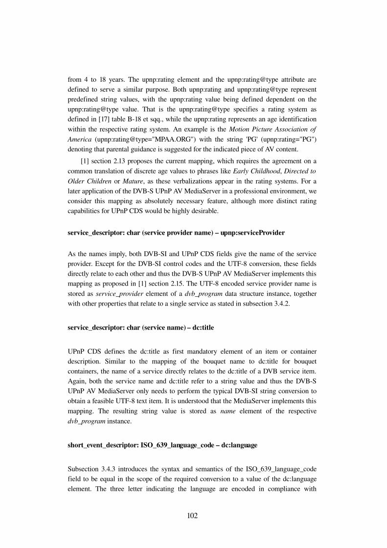
from 4 to 18 years. The upnp:rating element and the upnp:rating@type attribute are defined to serve a similar purpose. Both upnp:rating and upnp:rating@type represent predefined string values, with the upnp:rating value being defined dependent on the upnp:rating@type value. That is the upnp:rating@type specifies a rating system as defined in [17] table B18 et sqq., while the upnp:rating represents an age identification within the respective rating system. An example is the Motion Picture Association of America (upnp:rating@type="MPAA.ORG") with the string 'PG' (upnp:rating="PG") denoting that parental guidance is suggested for the indicated piece of AV content.
[1] section 2.13 proposes the current mapping, which requires the agreement on a common translation of discrete age values to phrases like Early Childhood, Directed to Older Children or Mature, as these verbalizations appear in the rating systems. For a later application of the DVBS UPnP AV MediaServer in a professional environment, we consider this mapping as absolutely necessary feature, although more distinct rating capabilities for UPnP CDS would be highly desirable.
service_descriptor: char (service provider name) – upnp:serviceProvider
As the names imply, both DVBSI and UPnP CDS fields give the name of the service provider. Except for the DVBSI control codes and the UTF8 conversion, these fields directly relate to each other and thus the DVBS UPnP AV MediaServer implements this mapping as proposed in [1] section 2.15. The UTF8 encoded service provider name is stored as service_provider element of a dvb_program data structure instance, together with other properties that relate to a single service as stated in subsection 3.4.2.
service_descriptor: char (service name) – dc:title
UPnP CDS defines the dc:title as first mandatory element of an item or container description. Similar to the mapping of the bouquet name to dc:title for bouquet containers, the name of a service directly relates to the dc:title of a DVB service item. Again, both the service name and dc:title refer to a string value and thus the DVBS UPnP AV MediaServer only needs to perform the typical DVBSI string conversion to obtain a feasible UTF8 text item. It is understood that the MediaServer implements this mapping. The resulting string value is stored as name element of the respective dvb_program instance.
short_event_descriptor: ISO_639_language_code – dc:language
Subsection 3.4.3 introduces the syntax and semantics of the ISO_639_language_code field to be equal in the scope of the required conversion to a value of the dc:language element. The three letter indicating the language are encoded in compliance with
102
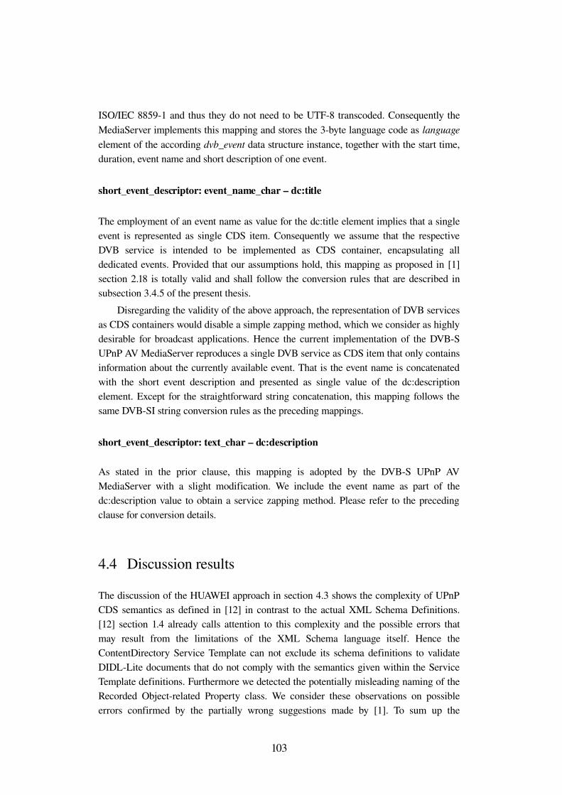
ISO/IEC 88591 and thus they do not need to be UTF8 transcoded. Consequently the MediaServer implements this mapping and stores the 3byte language code as language element of the according dvb_event data structure instance, together with the start time, duration, event name and short description of one event.
short_event_descriptor: event_name_char – dc:title
The employment of an event name as value for the dc:title element implies that a single event is represented as single CDS item. Consequently we assume that the respective DVB service is intended to be implemented as CDS container, encapsulating all dedicated events. Provided that our assumptions hold, this mapping as proposed in [1] section 2.18 is totally valid and shall follow the conversion rules that are described in subsection 3.4.5 of the present thesis.
Disregarding the validity of the above approach, the representation of DVB services as CDS containers would disable a simple zapping method, which we consider as highly desirable for broadcast applications. Hence the current implementation of the DVBS UPnP AV MediaServer reproduces a single DVB service as CDS item that only contains information about the currently available event. That is the event name is concatenated with the short event description and presented as single value of the dc:description element. Except for the straightforward string concatenation, this mapping follows the same DVBSI string conversion rules as the preceding mappings.
short_event_descriptor: text_char – dc:description
As stated in the prior clause, this mapping is adopted by the DVBS UPnP AV MediaServer with a slight modification. We include the event name as part of the dc:description value to obtain a service zapping method. Please refer to the preceding clause for conversion details.
4.4 Discussion results
The discussion of the HUAWEI approach in section 4.3 shows the complexity of UPnP CDS semantics as defined in [12] in contrast to the actual XML Schema Definitions. [12] section 1.4 already calls attention to this complexity and the possible errors that may result from the limitations of the XML Schema language itself. Hence the ContentDirectory Service Template can not exclude its schema definitions to validate DIDLLite documents that do not comply with the semantics given within the Service Template definitions. Furthermore we detected the potentially misleading naming of the Recorded Objectrelated Property class. We consider these observations on possible errors confirmed by the partially wrong suggestions made by [1]. To sum up the
103
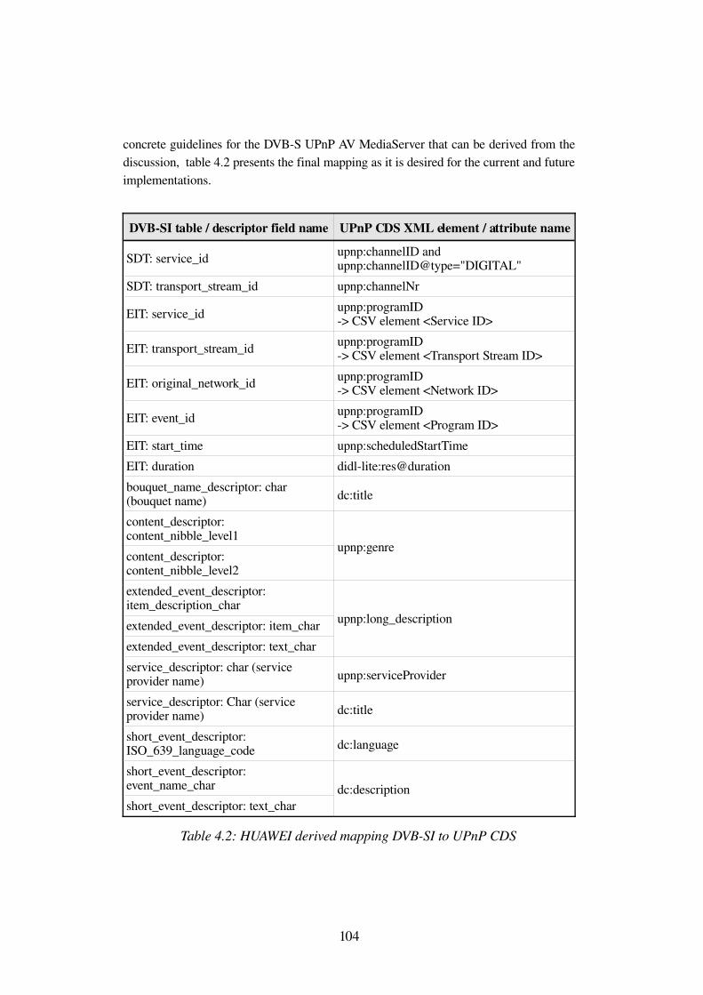
concrete guidelines for the DVBS UPnP AV MediaServer that can be derived from the discussion, table 4.2 presents the final mapping as it is desired for the current and future implementations.
DVBSI table / descriptor field name UPnP CDS XML element / attribute name
SDT: service_id upnp:channelID andupnp:channelID@type="DIGITAL"
SDT: transport_stream_id upnp:channelNr
EIT: service_id upnp:programID > CSV element <Service ID>
EIT: transport_stream_id upnp:programID > CSV element <Transport Stream ID>
EIT: original_network_id upnp:programID > CSV element <Network ID>
EIT: event_id upnp:programID > CSV element <Program ID>
EIT: start_time upnp:scheduledStartTimeEIT: duration didllite:res@durationbouquet_name_descriptor: char (bouquet name) dc:title
content_descriptor: content_nibble_level1content_descriptor: content_nibble_level2
upnp:genre
extended_event_descriptor: item_description_charextended_event_descriptor: item_charextended_event_descriptor: text_char
upnp:long_description
service_descriptor: char (service provider name) upnp:serviceProvider
service_descriptor: Char (service provider name) dc:title
short_event_descriptor: ISO_639_language_code dc:language
short_event_descriptor: event_name_charshort_event_descriptor: text_char
dc:description
Table 4.2: HUAWEI derived mapping DVBSI to UPnP CDS
104
Bibliography[1]: HUAWEI. Mapping SI into UPnP CDS. IPIdocumentnumber 2357 .April
2007.[2]: Microsoft Corporation. Understanding Universal Plug and Play Whitepaper
.June 2000.[3]: Network Working Group. Hypertext Transfer Protocol HTTP/1.1 .June
1999.[4]: World Wide Web Consortium. SOAP Version 1.2 Part 1: Messaging
Framework (Second Edition) .April 2007.[5]: Network Working Group. Dynamic Host Configuration Protocol .March
1997.[6]: Network Working Group. Dynamic Configuration of IPv4 LinkLocal
Addresses .May 2005.[7]: J. Postel. User Datagram Protocol .August 1980.[8]: Members of the UPnP Forum. UPnP Device Architecture Version 1.0 .July
2006.[9]: Members of the UPnP Forum. UPnP AV Architecture Version 1.0 for UPnP
Version 1.0 .June 2002.[10]: Members of the UPnP Forum. MediaServer:2 Device Template Version
1.01 for UPnP Version 1.0 .May 2006.[11]: Members of the UPnP Forum. MediaServer:2 Device Template Version
1.01 for UPnP Version 1.0 .May 2006.[12]: Members of the UPnP Forum. ContentDirectory:2 Service Template
Version 1.01 for UPnP Version 1.0 .May 2006.[13]: Members of the UPnP Forum. ConnectionManager:2 Service Template
Version 1.01 for UPnP Version 1.0 .May 2006.[14]: Members of the UPnP Forum. AVTransport:2 Service Template Version
1.01 for UPnP Version 1.0 .May 2006.[15]: Members of the UPnP Forum. RenderingControl:2 Service Template
Version 1.01 for UPnP Version 1.0 .May 2006.[16]: Network Working Group. Real Time Streaming Protocol (RTSP) .April
1998.[17]: Members of the UPnP Forum. ScheduledRecording:1 Service Template
Version 1.01 for UPnP Version 1.0 .May 2006.[18]: Members of the UPnP Forum. XML Schema for ContentDirectory:2
Structure and Metadata (DIDLLite) .May 2006.[19]: Members of the UPnP Forum. XML Schema for ContentDirectory:2
Metadata .May 2006.[20]: P.Johnston, C.Lagoze, A.Powell, H. Van de Sompel. XML Schema for
UPnP AV Dublin Core .December 2002.[21]: Yergeau, Bray, Paoli, SperbergMcQueen, Maler et al. Extensible Markup
Language (XML) 1.0 (Third Edition) .February 2004.[22]: Members of the Digital Living Network Alliance. DLNA Overview and
Vision Whitepaper . 2007.[23]: DVB Project TMIPI. DVBHN (Home Network) Reference Model Phase 1
.February 2007.[24]: European Telecommunications Standards Institute. ETSI TS 101154
Version 1.8.1: Specification for the use of Video and Audio Coding in Broadcasting Applications based on the MPEG2 Transport Stream .July 2007.
[25]: European Telecommunications Standards Institute. ETSI TS 102005 Version 1.3.1: Specification for the use of Video and Audio Coding in DVB services delivered directly over IP protocols .July 2007.
[26]: DVB Project. Digital Video Broadcasting Content Protection & Copy Management Bluebook .July 2007.
[27]: Members of the UPnP Forum. DeviceSecurity:1 Service Template for UPnP Device Architecture Version 1.0 . 2003.
[28]: Carl Ellison. SecurityConsole:1 Service Template for UPnP Device Architecture Version 1.0 .November 2003.
[29]: A. Gulbrandsen, P. Vixie, L. Esibov. A DNS RR for specifying the location of services (DNS SRV) .February 2000.
[30]: S. Alexander, R. Droms. DHCP Options and BOOTP Vendor Extensions .March 1997.
[31]: European Telecommunications Standards Institute. ETSI TS 102 034 Version 1.3.1 Transport of MPEG2 TS Based DVB Services over IP Based Networks . 2007.
[32]: Robert Müller. Binäre Codierung XMLbasierter DVBServiceInformationen Bachelor Thesis Lehrstuhl für Nachrichtentechnik Universität des Saarlandes.May 2007.
[33]: European Telecommunications Standards Institute. Digital Video Broadcasting (DVB);Framing structure, channel coding and modulation for 11/12 GHz satellite services .August 1997.
[34]: Simon Haykin, Michael Moher, Modern Wireless Communications, 2005[35]: Moving Picture Experts Group. ISO/IEC 138181 Second Edition
Information Technology Generic Coding of moving pictures and associated audio information: Systems .December 2000.
[36]: Moving Picture Experts Group. ISO/IEC 138182 Information Technology Generic Coding of Moving Pictures and Associated Audio: Audio . 1994.
[37]: Moving Picture Experts Group. ISO/IEC 138182 Information Technology Generic Coding of Moving Pictures and Associated Audio: Video . 1995.
[38]: European Telecommunications Standards Institute. ETSI EN 300468 Version 1.7.1 Digital Video Broadcasting (DVB); Specification for Service Information (SI) in DVB systems .May 2006.
[39]: European Telecommunications Standards Institute. ETSI TR 101211 Version 1.7.1 Digital Video Broadcasting (DVB); Guidelines on implementation and usage of Service Information (SI) .February 2006.
[40]: International Organization for Standardization. ISO/WD 8601 Data elements and interchange formats Information interchange Representation of dates and times .February 2003.
[41]: International Organization for Standardization. ISO 6392 Codes for the representation of names of languages Part 2: Alpha3 code .June 2006.
[42]: H. Alvestrand. RFC 3066 Tags for the Identification of Languages .January 2001.
[43]: International Organization for Standardization. ISO 3166 (all parts): Codes for the representation of names of countries and their subdivisions . .
[44]: European Telecommunications Standards Institute. ETR 162 Allocation of Service Information (SI) codes for Digital Video Broadcasting (DVB) systems .October 1995.
[45]: World Wide Web Consortium. XML Schema 1.1 Part 2: Datatypes .February 2006.


![UPnP & Konnex · Das UPnP Forum [UPnP-Forum]ist ein Zusammenschluss führender Hersteller aus der Unterhaltungs- und Computerindustrie. Es wurde im Juni 1999 gegründet und zählt](https://img.pdfslide.org/doc/110x75/5e1bff200e2a4a15a230d247/upnp-das-upnp-forum-upnp-forumist-ein-zusammenschluss-fhrender-hersteller.jpg)
![PIR Solar Wall Light Ljuskänslighet för aktivering av belysningen mäts av en fotocell som känner av ljus och mörker. Justera steglöst med vredet [ SENSOR LEVEL ] enligt pilsymbolen](https://img.pdfslide.org/doc/110x75/5aae370d7f8b9adb688c00d2/pir-solar-wall-light-ljusknslighet-fr-aktivering-av-belysningen-mts-av-en-fotocell.jpg)