Embed Size (px)
Citation preview
A HYGROTHERMAL BUILDING MODEL BASED ON THE OBJECT-ORIENTED MODELING LANGUAGE MODELICA
Christoph Nytsch-Geusen1, Thierry Nouidui2, Andreas Holm2 and Wolfram Haupt3
1Fraunhofer Institute for Computer Architecture and Software Technology (FIRST), Kekuléstr. 7, D-12489 Berlin, [email protected]
2Fraunhofer IBP, Holzkirchen, Germany 3Technische Universität München, Lehrstuhl für Bauphysik, München, Germany
ABSTRACT
A new hygrothermal building model is being developed within the research project GENSIM by the Fraunhofer institutes FIRST and IBP. The model implementation takes place by using the object-oriented modeling language Modelica. As a starting point for the development of the new building model, the researchers used the physical models of the simulation tools WUFI (hygrothermal wall simulation) and SMILE (thermal building simulation). The first results of this research are Modelica-implementations of a thermal and a hygrothermal wall model and its comparision with the well validated program WUFI. The present research implements further Modelica models for air volume, windows, zones, inhabitants and the building environment in order to get a model library for simulating whole buildings. The coupled hygrothermal physical effects in the building envelope are also considered. The hygrothermal building model will be validated by test-rooms at Fraunhofer IBP.
INTRODUCTION In the area of building physics hygrothermal models for one or a set of building components (e.g walls or floors) are widely used to compute the coupled transport processes of heat and moisture for one- or multidimensional cases. In those models, however, the boundary conditions of heat and moisture have to be user-defined before starting the simulation.
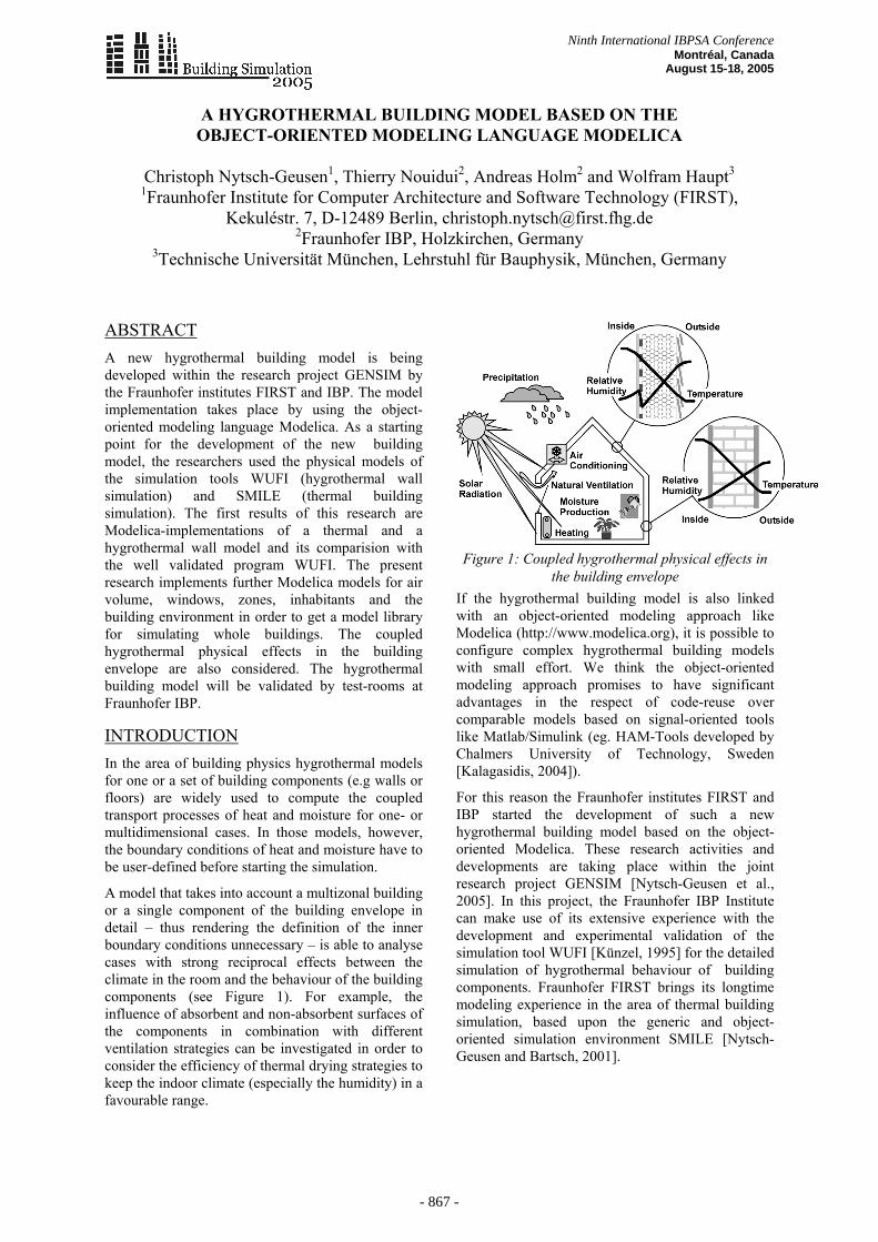
A model that takes into account a multizonal building or a single component of the building envelope in detail – thus rendering the definition of the inner boundary conditions unnecessary – is able to analyse cases with strong reciprocal effects between the climate in the room and the behaviour of the building components (see Figure 1). For example, the influence of absorbent and non-absorbent surfaces of the components in combination with different ventilation strategies can be investigated in order to consider the efficiency of thermal drying strategies to keep the indoor climate (especially the humidity) in a favourable range.
Figure 1: Coupled hygrothermal physical effects in
the building envelope If the hygrothermal building model is also linked with an object-oriented modeling approach like Modelica (http://www.modelica.org), it is possible to configure complex hygrothermal building models with small effort. We think the object-oriented modeling approach promises to have significant advantages in the respect of code-reuse over comparable models based on signal-oriented tools like Matlab/Simulink (eg. HAM-Tools developed by Chalmers University of Technology, Sweden [Kalagasidis, 2004]).
For this reason the Fraunhofer institutes FIRST and IBP started the development of such a new hygrothermal building model based on the object-oriented Modelica. These research activities and developments are taking place within the joint research project GENSIM [Nytsch-Geusen et al., 2005]. In this project, the Fraunhofer IBP Institute can make use of its extensive experience with the development and experimental validation of the simulation tool WUFI [Künzel, 1995] for the detailed simulation of hygrothermal behaviour of building components. Fraunhofer FIRST brings its longtime modeling experience in the area of thermal building simulation, based upon the generic and object-oriented simulation environment SMILE [Nytsch-Geusen and Bartsch, 2001].
Ninth International IBPSA Conference Montréal, Canada
August 15-18, 2005
- 867 -
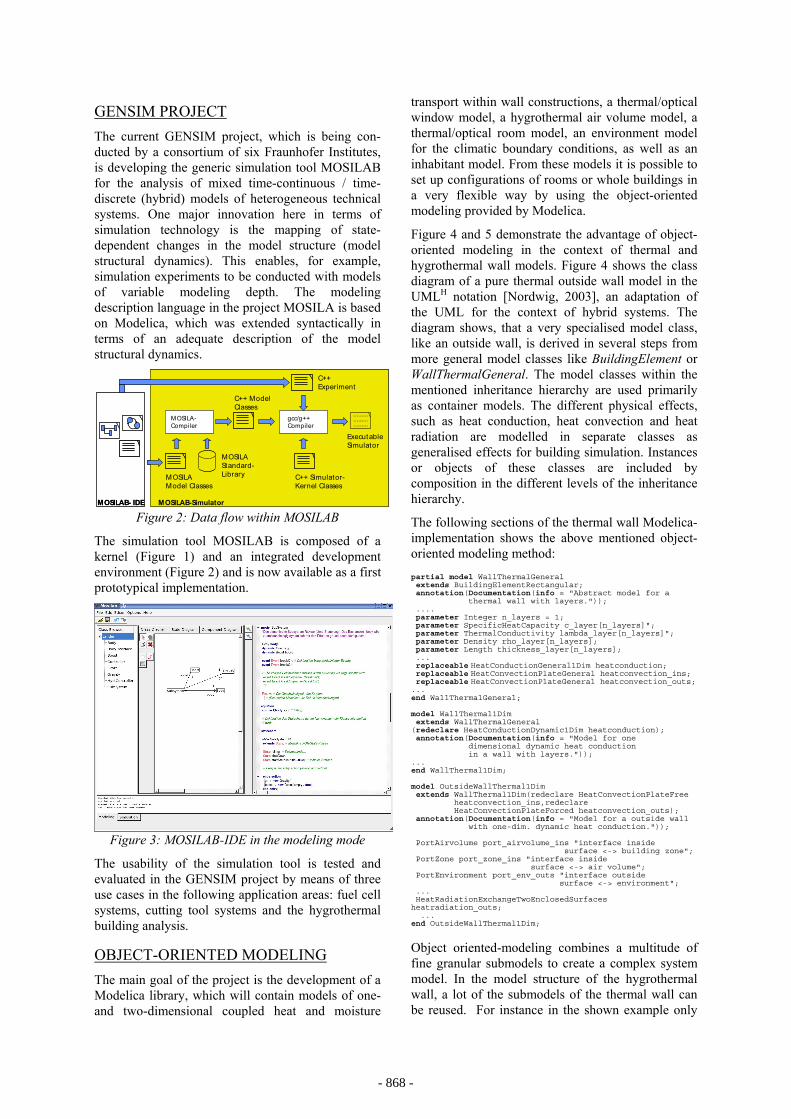
GENSIM PROJECT The current GENSIM project, which is being con-ducted by a consortium of six Fraunhofer Institutes, is developing the generic simulation tool MOSILAB for the analysis of mixed time-continuous / time-discrete (hybrid) models of heterogeneous technical systems. One major innovation here in terms of simulation technology is the mapping of state-dependent changes in the model structure (model structural dynamics). This enables, for example, simulation experiments to be conducted with models of variable modeling depth. The modeling description language in the project MOSILA is based on Modelica, which was extended syntactically in terms of an adequate description of the model structural dynamics.
MOSILAB- IDE
MOSILA-Compiler
gcc/g++ Compiler
C++ Model Classes
MOSILA Model Classes
C++ Simulator-Kernel Classes
010110101O10100101111010101
ExecutableSimulator
MOSILAB-Simulator
MOSILA Standard-Library
C++ Experiment
MOSILAB- IDE
MOSILA-Compiler
gcc/g++ Compiler
C++ Model Classes
MOSILA Model Classes
C++ Simulator-Kernel Classes
010110101O10100101111010101
ExecutableSimulator
MOSILAB-Simulator
MOSILA Standard-Library
C++ Experiment
Figure 2: Data flow within MOSILAB
The simulation tool MOSILAB is composed of a kernel (Figure 1) and an integrated development environment (Figure 2) and is now available as a first prototypical implementation.
Figure 3: MOSILAB-IDE in the modeling mode
The usability of the simulation tool is tested and evaluated in the GENSIM project by means of three use cases in the following application areas: fuel cell systems, cutting tool systems and the hygrothermal building analysis.
OBJECT-ORIENTED MODELING The main goal of the project is the development of a Modelica library, which will contain models of one- and two-dimensional coupled heat and moisture
transport within wall constructions, a thermal/optical window model, a hygrothermal air volume model, a thermal/optical room model, an environment model for the climatic boundary conditions, as well as an inhabitant model. From these models it is possible to set up configurations of rooms or whole buildings in a very flexible way by using the object-oriented modeling provided by Modelica.
Figure 4 and 5 demonstrate the advantage of object-oriented modeling in the context of thermal and hygrothermal wall models. Figure 4 shows the class diagram of a pure thermal outside wall model in the UMLH notation [Nordwig, 2003], an adaptation of the UML for the context of hybrid systems. The diagram shows, that a very specialised model class, like an outside wall, is derived in several steps from more general model classes like BuildingElement or WallThermalGeneral. The model classes within the mentioned inheritance hierarchy are used primarily as container models. The different physical effects, such as heat conduction, heat convection and heat radiation are modelled in separate classes as generalised effects for building simulation. Instances or objects of these classes are included by composition in the different levels of the inheritance hierarchy.
The following sections of the thermal wall Modelica-implementation shows the above mentioned object-oriented modeling method: partial model WallThermalGeneral extends BuildingElementRectangular; annotation(Documentation(info = "Abstract model for a thermal wall with layers.")); .... parameter Integer n_layers = 1; parameter SpecificHeatCapacity c_layer[n_layers]"; parameter ThermalConductivity lambda_layer[n_layers]"; parameter Density rho_layer[n_layers]; parameter Length thickness_layer[n_layers]; ... replaceable HeatConductionGeneral1Dim heatconduction; replaceable HeatConvectionPlateGeneral heatconvection_ins; replaceable HeatConvectionPlateGeneral heatconvection_outs;
... end WallThermalGeneral; model WallThermal1Dim extends WallThermalGeneral (redeclare HeatConductionDynamic1Dim heatconduction); annotation(Documentation(info = "Model for one dimensional dynamic heat conduction in a wall with layers.")); ... end WallThermal1Dim; model OutsideWallThermal1Dim extends WallThermal1Dim(redeclare HeatConvectionPlateFree heatconvection_ins,redeclare HeatConvectionPlateForced heatconvection_outs); annotation(Documentation(info = "Model for a outside wall with one-dim. dynamic heat conduction.")); PortAirvolume port_airvolume_ins "interface inside surface <-> building zone"; PortZone port_zone_ins "interface inside surface <-> air volume"; PortEnvironment port_env_outs "interface outside surface <-> environment"; ... HeatRadiationExchangeTwoEnclosedSurfaces heatradiation_outs; ... end OutsideWallThermal1Dim;
Object oriented-modeling combines a multitude of fine granular submodels to create a complex system model. In the model structure of the hygrothermal wall, a lot of the submodels of the thermal wall can be reused. For instance in the shown example only
- 868 -
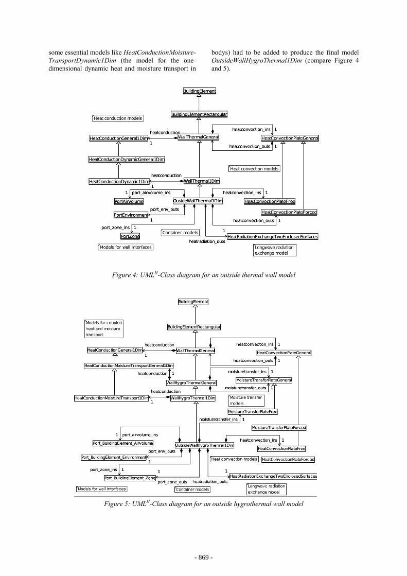
some essential models like HeatConductionMoisture-TransportDynamic1Dim (the model for the one-dimensional dynamic heat and moisture transport in
bodys) had to be added to produce the final model OutsideWallHygroThermal1Dim (compare Figure 4 and 5).
Figure 4: UMLH-Class diagram for an outside thermal wall model
Figure 5: UMLH-Class diagram for an outside hygrothermal wall model
- 869 -
PHYSICAL WALL MODEL A hygrothermal wall model based on the physical model for heat and moisture transfer in building components [Künzel, 1995] was implemented in Modelica. For modeling in Modelica, the energy balance (1) and the mass balance (2) for the one-dimensional case written as partial differential equations, were transferred in a set of ordinary differential equations by local discretisation. Energy balance (one-dimensional)
(1)
[( ) )]
satv p
t w
t s s
ew e w e e e
pdH hdt x x x x
H H HH c
dwH w w c w c hd
ϕϑλ δ
ρ ϑ
ϑϑ
∂∂ ∂ ∂ = ⋅ + ⋅ ∂ ∂ ∂ ∂ = +
=
= − + − ⋅
Mass balance (one-dimensional)
(2)
( 1)
satp
f
pdw Ddt x x x
bw wb
ϕϕϕ δ
ϕϕ
∂∂ ∂ = ⋅ + ∂ ∂ ∂ −
=−
The local discretisation was realised by replacing the local partial derivatives occurring in the equations (1) and (2) with finite differences. This discretisation was necessary, because the current specification of Modelica and the available Modelica simulation tools can not solve partial differential equations.
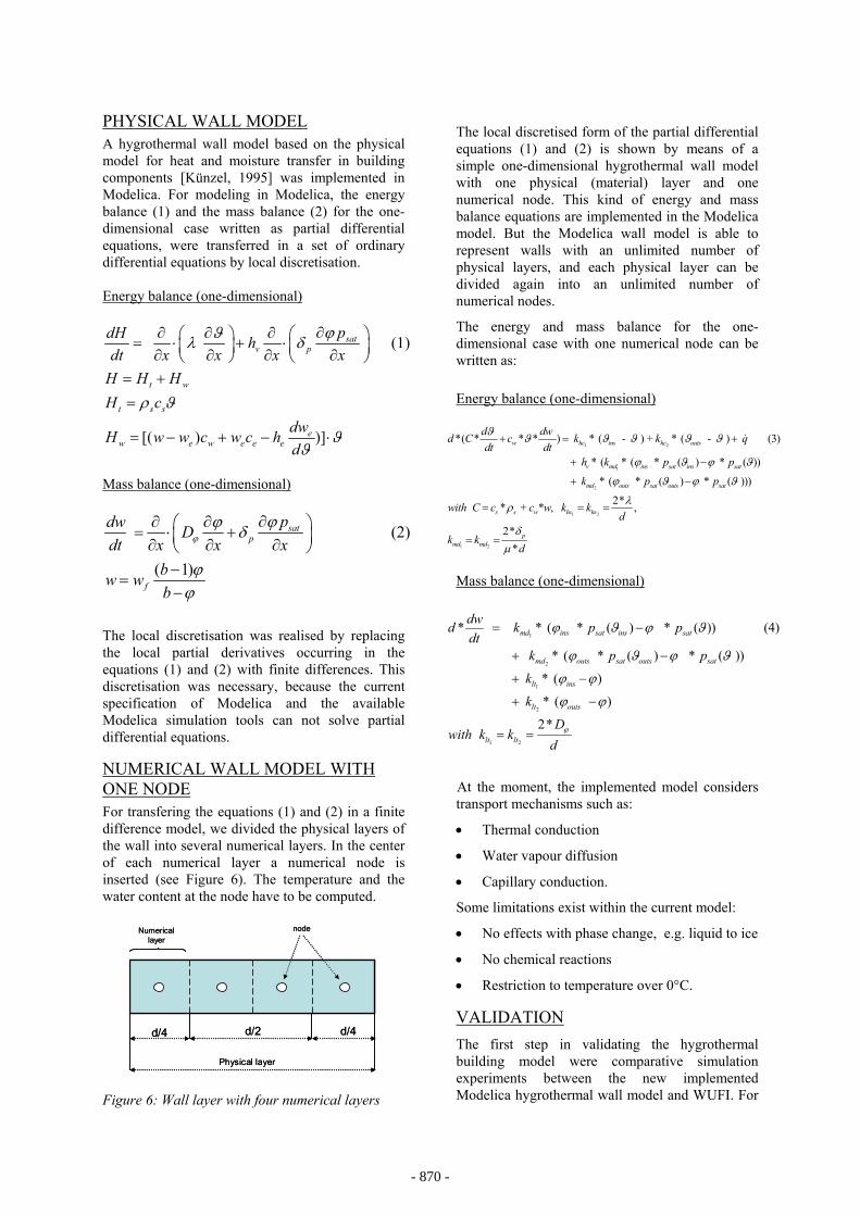
NUMERICAL WALL MODEL WITH ONE NODE For transfering the equations (1) and (2) in a finite difference model, we divided the physical layers of the wall into several numerical layers. In the center of each numerical layer a numerical node is inserted (see Figure 6). The temperature and the water content at the node have to be computed.
d/2 d/4d/4
nodeNumericallayer
Physical layer
d/2 d/4d/4
nodeNumericallayer
Physical layer Figure 6: Wall layer with four numerical layers
The local discretised form of the partial differential equations (1) and (2) is shown by means of a simple one-dimensional hygrothermal wall model with one physical (material) layer and one numerical node. This kind of energy and mass balance equations are implemented in the Modelica model. But the Modelica wall model is able to represent walls with an unlimited number of physical layers, and each physical layer can be divided again into an unlimited number of numerical nodes.
The energy and mass balance for the one-dimensional case with one numerical node can be written as: Energy balance (one-dimensional)
1 2
1
*( * * * ) * ( - ) + * ( - ) (3)
* ( * ( * ( ) * ( ))
w hc ins hc outs
v md ins sat ins sat
d dwd C c k k qdt dt
h k p p
ϑ ϑ ϑ ϑ ϑ ϑ
ϕ ϑ ϕ ϑ
+ = +
+ −
&
2
1 2
1 2
* ( * ( ) * ( )))
2* * + * , ,
2**
md outs sat outs sat
s s w hc hc
pmd md
k p p
with C c c w k kd
k kd
ϕ ϑ ϕ ϑ
λρ
δµ
+ −
= = =
= =
Mass balance (one-dimensional)
1
2
1
2
* * ( * ( ) * ( )) (4)
* ( * ( ) * ( ))
* ( )
* ( )
md ins sat ins sat
md outs sat outs sat
lt ins
lt outs
dwd k p pdt
k p p
k
k
with
ϕ ϑ ϕ ϑ
ϕ ϑ ϕ ϑ
ϕ ϕ
ϕ ϕ
= −
+ −
+ −
+ −
1 2
2* lt lt
Dk k
dϕ= =
At the moment, the implemented model considers transport mechanisms such as:
• Thermal conduction
• Water vapour diffusion
• Capillary conduction.
Some limitations exist within the current model:
• No effects with phase change, e.g. liquid to ice
• No chemical reactions
• Restriction to temperature over 0°C.
VALIDATION The first step in validating the hygrothermal building model were comparative simulation experiments between the new implemented Modelica hygrothermal wall model and WUFI. For
- 870 -
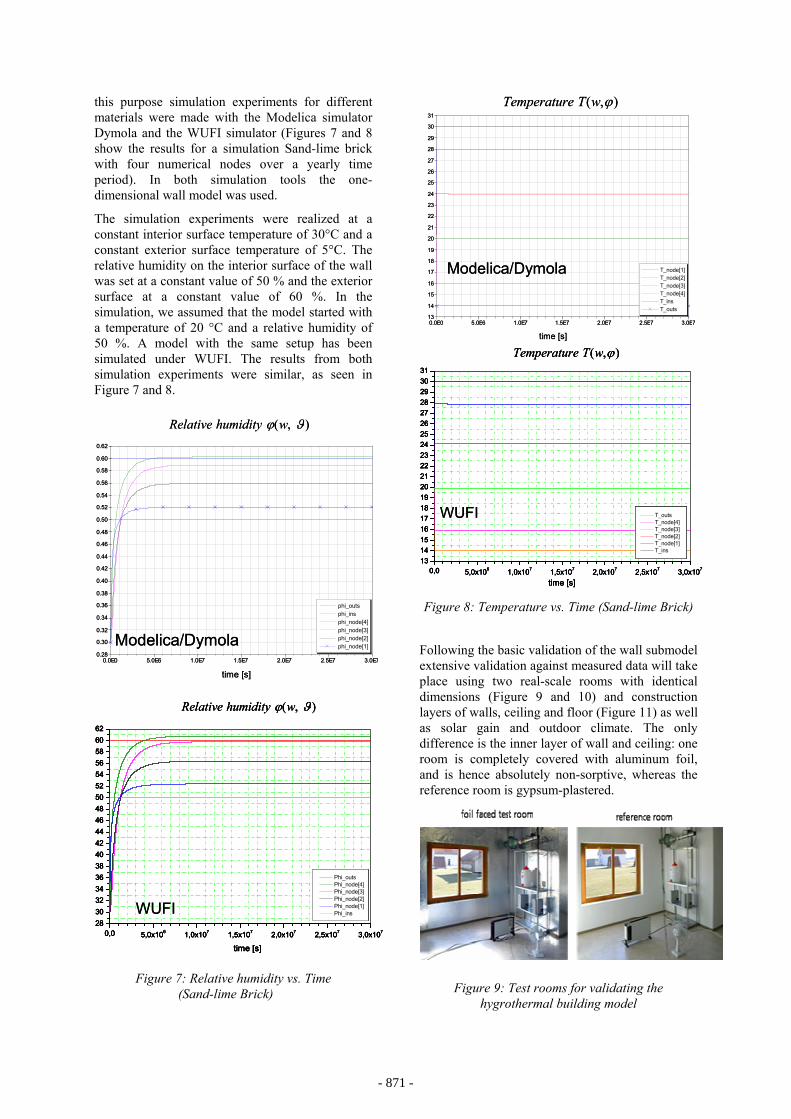
this purpose simulation experiments for different materials were made with the Modelica simulator Dymola and the WUFI simulator (Figures 7 and 8 show the results for a simulation Sand-lime brick with four numerical nodes over a yearly time period). In both simulation tools the one-dimensional wall model was used.
The simulation experiments were realized at a constant interior surface temperature of 30°C and a constant exterior surface temperature of 5°C. The relative humidity on the interior surface of the wall was set at a constant value of 50 % and the exterior surface at a constant value of 60 %. In the simulation, we assumed that the model started with a temperature of 20 °C and a relative humidity of 50 %. A model with the same setup has been simulated under WUFI. The results from both simulation experiments were similar, as seen in Figure 7 and 8.
0.0E0 5.0E6 1.0E7 1.5E7 2.0E7 2.5E7 3.0E70.28
0.30
0.32
0.34
0.36
0.38
0.40
0.42
0.44
0.46
0.48
0.50
0.52
0.54
0.56
0.58
0.60
0.62
phi_outs phi_insphi_node[4]phi_node[3]phi_node[2]phi_node[1]Modelica/Dymola
( , )Relative humidity wϕ ϑ
time [s]
0.0E0 5.0E6 1.0E7 1.5E7 2.0E7 2.5E7 3.0E70.28
0.30
0.32
0.34
0.36
0.38
0.40
0.42
0.44
0.46
0.48
0.50
0.52
0.54
0.56
0.58
0.60
0.62
phi_outs phi_insphi_node[4]phi_node[3]phi_node[2]phi_node[1]Modelica/Dymola
( , )Relative humidity wϕ ϑ
time [s]
( , )Relative humidity wϕ ϑ
0,0 5,0x10⁶ 1,0x10⁷ 1,5x10⁷ 2,0x10⁷ 2,5x10⁷ 3,0x107283032343638404244464850525456586062
Phi_outs Phi_node[4] Phi_node[3] Phi_node[2] Phi_node[1] Phi_ins
time [s]
WUFI
( , )Relative humidity wϕ ϑ
0,0 5,0x10⁶ 1,0x10⁷ 1,5x10⁷ 2,0x10⁷ 2,5x10⁷ 3,0x107283032343638404244464850525456586062
Phi_outs Phi_node[4] Phi_node[3] Phi_node[2] Phi_node[1] Phi_ins
time [s]
( , )Relative humidity wϕ ϑ
0,0 5,0x10⁶ 1,0x10⁷ 1,5x10⁷ 2,0x10⁷ 2,5x10⁷ 3,0x107283032343638404244464850525456586062
Phi_outs Phi_node[4] Phi_node[3] Phi_node[2] Phi_node[1] Phi_ins
time [s]
0,0 5,0x10⁶ 1,0x10⁷ 1,5x10⁷ 2,0x10⁷ 2,5x10⁷ 3,0x107283032343638404244464850525456586062
Phi_outs Phi_node[4] Phi_node[3] Phi_node[2] Phi_node[1] Phi_ins
time [s]
WUFI
Figure 7: Relative humidity vs. Time
(Sand-lime Brick)
0.0E0 5.0E6 1.0E7 1.5E7 2.0E7 2.5E7 3.0E713
14
15
16
17
18
19
20
21
22
23
24
25
26
27
28
29
30
31
T_node[1]T_node[2]T_node[3]T_node[4]T_insT_outs
( , )Temperature T w ϕ
time [s]
Modelica/Dymola
0.0E0 5.0E6 1.0E7 1.5E7 2.0E7 2.5E7 3.0E713
14
15
16
17
18
19
20
21
22
23
24
25
26
27
28
29
30
31
T_node[1]T_node[2]T_node[3]T_node[4]T_insT_outs
( , )Temperature T w ϕ
time [s]
Modelica/Dymola
0,0 5,0x10⁶ 1,0x10⁷ 1,5x10⁷ 2,0x10⁷ 2,5x10⁷ 3,0x10713141516171819202122232425262728293031
T_outs T_node[4] T_node[3] T_node[2] T_node[1] T_ins
time [s]
( , )Temperature T w ϕ
WUFI
0,0 5,0x10⁶ 1,0x10⁷ 1,5x10⁷ 2,0x10⁷ 2,5x10⁷ 3,0x10713141516171819202122232425262728293031
T_outs T_node[4] T_node[3] T_node[2] T_node[1] T_ins
time [s]
( , )Temperature T w ϕ
0,0 5,0x10⁶ 1,0x10⁷ 1,5x10⁷ 2,0x10⁷ 2,5x10⁷ 3,0x10713141516171819202122232425262728293031
T_outs T_node[4] T_node[3] T_node[2] T_node[1] T_ins
time [s]0,0 5,0x10⁶ 1,0x10⁷ 1,5x10⁷ 2,0x10⁷ 2,5x10⁷ 3,0x10⁷
13141516171819202122232425262728293031
T_outs T_node[4] T_node[3] T_node[2] T_node[1] T_ins
time [s]
( , )Temperature T w ϕ
WUFI
Figure 8: Temperature vs. Time (Sand-lime Brick)
Following the basic validation of the wall submodel extensive validation against measured data will take place using two real-scale rooms with identical dimensions (Figure 9 and 10) and construction layers of walls, ceiling and floor (Figure 11) as well as solar gain and outdoor climate. The only difference is the inner layer of wall and ceiling: one room is completely covered with aluminum foil, and is hence absolutely non-sorptive, whereas the reference room is gypsum-plastered.
Figure 9: Test rooms for validating the hygrothermal building model
- 871 -
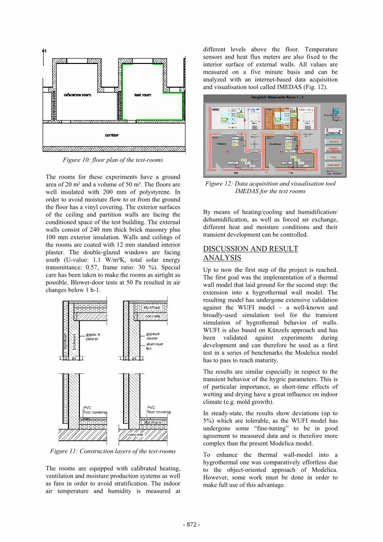
Figure 10: floor plan of the test-rooms
The rooms for these experiments have a ground area of 20 m² and a volume of 50 m³. The floors are well insulated with 200 mm of polystyrene. In order to avoid moisture flow to or from the ground the floor has a vinyl covering. The exterior surfaces of the ceiling and partition walls are facing the conditioned space of the test building. The external walls consist of 240 mm thick brick masonry plus 100 mm exterior insulation. Walls and ceilings of the rooms are coated with 12 mm standard interior plaster. The double-glazed windows are facing south (U-value: 1.1 W/m²K, total solar energy transmittance: 0.57, frame ratio: 30 %). Special care has been taken to make the rooms as airtight as possible. Blower-door tests at 50 Pa resulted in air changes below 1 h-1.
Figure 11: Construction layers of the test-rooms
The rooms are equipped with calibrated heating, ventilation and moisture production systems as well as fans in order to avoid stratification. The indoor air temperature and humidity is measured at
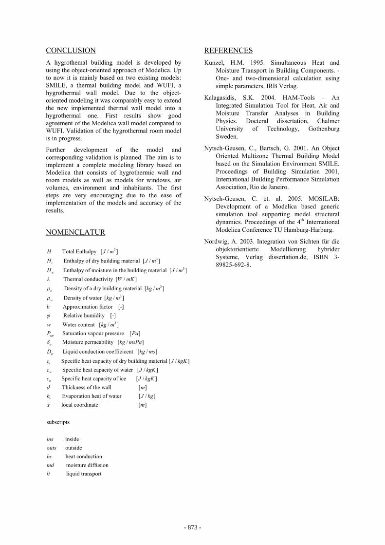
different levels above the floor. Temperature sensors and heat flux meters are also fixed to the interior surface of external walls. All values are measured on a five minute basis and can be analyzed with an internet-based data acquisition and visualisation tool called IMEDAS (Fig. 12).
Figure 12: Data acquisition and visualisation tool
IMEDAS for the test rooms
By means of heating/cooling and humidification/ dehumidification, as well as forced air exchange, different heat and moisture conditions and their transient development can be controlled.
DISCUSSION AND RESULT ANALYSIS Up to now the first step of the project is reached. The first goal was the implementation of a thermal wall model that laid ground for the second step: the extension into a hygrothermal wall model. The resulting model has undergone extensive validation against the WUFI model – a well-known and broadly-used simulation tool for the transient simulation of hygrothemal behavior of walls. WUFI is also based on Künzels approach and has been validated against experiments during development and can therefore be used as a first test in a series of benchmarks the Modelica model has to pass to reach maturity.
The results are similar especially in respect to the transient behavior of the hygric parameters. This is of particular importance, as short-time effects of wetting and drying have a great influence on indoor climate (e.g. mold growth).
In steady-state, the results show deviations (up to 5%) which are tolerable, as the WUFI model has undergone some “fine-tuning” to be in good agreement to measured data and is therefore more complex than the present Modelica model.
To enhance the thermal wall-model into a hygrothermal one was comparatively effortless due to the object-oriented approach of Modelica. However, some work must be done in order to make full use of this advantage.
- 872 -
CONCLUSION A hygrothemal building model is developed by using the object-oriented approach of Modelica. Up to now it is mainly based on two existing models: SMILE, a thermal building model and WUFI, a hygrothermal wall model. Due to the object-oriented modeling it was comparably easy to extend the new implemented thermal wall model into a hygrothermal one. First results show good agreement of the Modelica wall model compared to WUFI. Validation of the hygrothermal room model is in progress.
Further development of the model and corresponding validation is planned. The aim is to implement a complete modeling library based on Modelica that consists of hygrothermic wall and room models as well as models for windows, air volumes, environment and inhabitants. The first steps are very encouraging due to the ease of implementation of the models and accuracy of the results.
NOMENCLATUR
3
3
3
Total Enthalpy [ / ] Enthalpy of dry building material [ / ]
Enthalpy of moisture in the building material [ / ] Thermal conductivity [ / ]
t
w
s
H J mH J m
H J mW mKλ
ρ 3
3
3
Density of a dry building material [ / ]
Density of water [ / ] Approximation factor [-] Relative humidity [-] Water content [ / ]
Satur
w
sat
kg m
kg mb
w kg mP
ρ
ϕ
p
s
ation vapour pressure [ ] Moisture permeability [ / ]
Liquid conduction coefficicent [ / ]
Specific heat capacity of dry building material [ / ] Sw
Pakg msPa
D kg ms
c J kgKc
ϕ
δ
e
pecific heat capacity of water [ / ] Specific heat capacity of ice [ / ]
Thickness of the wall [ ] Evaporation heat
J kgKc J kgKd mhν of water [ / ]
local coordinate [ ]
subscripts
inside outside
heat conduction moisture diffusion
li
J kgx m
insoutshcmdlt quid transport
REFERENCES Künzel, H.M. 1995. Simultaneous Heat and
Moisture Transport in Building Components. - One- and two-dimensional calculation using simple parameters. IRB Verlag.
Kalagasidis, S.K. 2004. HAM-Tools – An Integrated Simulation Tool for Heat, Air and Moisture Transfer Analyses in Building Physics. Docteral dissertation, Chalmer University of Technology, Gothenburg Sweden.
Nytsch-Geusen, C., Bartsch, G. 2001. An Object Oriented Multizone Thermal Building Model based on the Simulation Environment SMILE. Proceedings of Building Simulation 2001, International Building Performance Simulation Association, Rio de Janeiro.
Nytsch-Geusen, C. et. al. 2005. MOSILAB: Development of a Modelica based generic simulation tool supporting model structural dynamics. Proceedings of the 4th International Modelica Conference TU Hamburg-Harburg.
Nordwig, A. 2003. Integration von Sichten für die objektorientierte Modellierung hybrider Systeme, Verlag dissertation.de, ISBN 3-89825-692-8.
- 873 -

- 874 -