Embed Size (px)
Citation preview
TECHNISCHE • •
UNIVERSITAT
WIEN
Vienna I Austria
Dekanat der Fakultät für Maschinenwesen und Betriebswissenschaften
MERKBLATT FÜR DOKTORATSWERBERund Formulare für die Dissertation / Rigorosum
1) Allgemeine Informationen
Jeder in- und ausländische Doktoratswerber muss als ordentliche/r Studierende/r für das Doktoratsstudium zugelassen sein. (Die Zulassung ist erloschen, wenn der/dieStudierende sich vom Studium abgemeldet oder mehr als zwei Semester die Meldung der Fortsetzung des Studiums unterlassen hat. Eine neuerliche Zulassung ist nur während der allgemeinen Zulassungsfristen möglich.)
Eine Frist zwischen der Einreichung der Dissertation zur Approbation und der Ablegung desRigorosums besteht grundsätzlich nicht. Die Einreichung muss jedoch so rechtzeitig erfolgen, dass den Begutachtern genügend Zeit zur Abfassung ihrer Gutachten und zur Beurteilung bleibt. Dieser Zeitraum liegt im Ermessen der Gutachter, doch ist mit mindestens sechs Wochen zu rechnen. Gemäß § 62 Abs.7 UniStG sind Dissertationen jedenfalls innerhalb von vier Monaten zu beurteilen. Die Approbation der Dissertation ist Voraussetzung für die Zulassung zum Rigorosum.
2) Einreichung der Dissertation
Folgende Formulare und Dokumente sind im Dekanat (Parteienverkehr: MO - DO: 10:00 – 12:00 Uhr) einzureichen:
1. Lebenslauf2. Geburtsurkunde3. Diplomzeugnis des letzten akademischen Grades4. Antrag auf Benützungsbeschränkung
(bei Bedarf unter TISS-Abschlussarbeiten zu erstellen)5. Aktuelles Studienbuchblatt6. Kopie der ersten Seite der Dissertation7. Best. über absolvierte LVA (12 Wochenstunden. bzw. 18 ECTS +Sammelzeugnis)8. Zwei unterschriebene, gebundene Dissertationsexemplare9. Merkblatt für Verfasser/innen für Hochschulschriften10. Positive Stellungnahme
Dissertationen sind grundsätzlich in deutscher Sprache abzufassen, sie können jedoch ineiner Fremdsprache abgefasst werden, wenn der/die Betreuer/in zugestimmt hat.
Dissertation
Adaptable Engineering SupportFramework for Multi-FunctionalBattery Energy Storage Systems
carried out for the purpose of obtaining the degree of Doctor technicae (Dr. techn.)submitted at TU Wien, Faculty of Mechanical and Industrial Engineering,
by
Claudia ZANABRIAMatr.Nr.: 01528041
under the supervision of
Privatdoz. Dr. Thomas I. StrasserInstitute of Mechanics and Mechatronics (E325)Division of Control and Process Automation
reviewed by
A.o.Univ.Prof. Dr. Wolfgang Kastner Univ.Prof. Dr. Alois ZoitlVienna University of Technology (E191) Johannes Kepler UniversityInstitute of Computer Engineering Linz Institute of TechnologyKarlsplatz 13, 1040 Wien Altenberger Straße 69, 4040 Linz
Die approbierte Originalversion dieser Dissertation ist in der Hauptbibliothek der Technischen Universität Wien aufgestellt und zugänglich. http://www.ub.tuwien.ac.at
The approved original version of this thesis is available at the main library of the Vienna University of Technology.
http://www.ub.tuwien.ac.at/eng

I confirm, that going to press of this thesis needs the confirmation of the examinationcommittee.
Affidavit
I declare in lieu of oath, that I wrote this thesis and performed the associated researchmyself, using only literature cited in this volume. If text passages from sources are usedliterally, they are marked as such.
I confirm that this work is original and has not been submitted elsewhere for anyexamination, nor is it currently under consideration for a thesis elsewhere.
Vienna, am 19. November 2018 Claudia Zanabria

This thesis is dedicated to
Mili, Ivan, Fabrizzio, Claudio y Susy.

Acknowledgment iii
AcknowledgmentI would like to express my sincere gratitude to my advisor Thomas Strasser as well asto my collegue Filip Pröstl Andrén for many fruitful and interesting discussions, fortheir patience, encouragement and continuous support over the last fours years duringthe realization of this thesis.

Kurzfassung iv
KurzfassungMultifunktionale Batteriespeichersysteme gelangen zunehmend an Bedeutung, da sienicht nur einen Beitrag zur Eigenverbrauchsabdeckung von Konsumenten, sondern auchzur Stützung des Betriebs von elektrischen Verteilnetzen beitragen können. Darüber hin-aus können diese Speichersysteme auch an diversen Energiemarktdiensten teilnehmen.Üblicherweise werden die vorhin genannten Speicherdienste in zugehörigen Energieman-gementsystemen implementiert, wo oftmals zeitnah auch andere Services bedient werdenmüssen. Die Realisierung im jeweiligen Zielsystem wird ebenfalls anspruchsvoller, da esdurch die Anzahl und Komplexität der diversen Dienste und Services zu möglichenkonfliktären Zuständen kommen kann. Aktuelle Steuerungsimplementierungen dieserSpeichersystems lassen eine flexible Handhabung dieser Situationen oftmals nicht zu.Da auch zukünftig eine großflächige Installation dieser Geräte im Feld erwartet wird, istein entsprechender Engineering- und Implementierungsansatz, der eine schnelle Anpas-sung an geänderte Rahmenbedingungen ermöglicht, notwendig. Aktuelle Ansätze sindnur bedingt dazu geeignet; ein integrativer Entwicklungsansatz mit zugehörigen Toolsist daher notwendig.
Die in dieser Arbeit vorgeschlagene Lösung basiert auf modernen Ansätzen aus der In-formatik und des Systems- bzw. Wissensengineerings. Die Basis bildet dabei eine aufeiner Ontologie beruhenden Wissensrepräsentation von Diensten bzw. Services einesmultifunktionalen Batteriespeichersystems. Des Weiteren werden einschlägige Normenund Standards berücksichtigt, um eine interoperable Lösung zu gewährleisten. Ebenfallswerden Inferenzverfahren als ein wesentliches Merkmal von Ontologien zur Identifika-tion von potentiellen Steuerungskonflikten verwendet.
Das Hauptergebnis dieser Arbeit ist daher eine Art Entwicklungs- und Implementie-rungsframework für Batteriespeichersysteme, die eine rasche Umsetzung von zugehöri-gen Applikationen ermöglicht. Um das Potential der vorgeschlagenen Lösung validie-ren und mit gebräuchlichen Ansätzen vergleichen zu können, wurde eine prototypischeRealisierung an ausgewählten Anwendungsfällen simulativ als auch labortechnisch um-gesetzt. Die erzielten Ergebnisse sind dabei vielversprechend verglichen mit herkömm-lichen Design- und Entwicklungsansätzen.
Abstract v
AbstractMulti-functional battery energy storage systems are getting popular since they can offernot only self-consumption but other services that contribute to the stability of supplyof power grids. Furthermore, those storages may also participate in market services,demand response, among others. They are usually implemented in corresponding en-ergy management systems. Therefore, those systems should carry out a simultaneousoperation of services and be interoperable with different other actors and devices inthe domain of power and energy systems. The implementation of the referred systemsbecomes a challenging task since unattended couplings across services may harm theiroverall operation. Furthermore, current engineering approaches are not flexible enoughto accept an easy and rapid integration of new components. In addition, since a massivedeployment of battery energy storage system is expected in a near future, a rapid pro-totyping of their corresponding services becomes a requirement. The mentioned issuesshould be addressed during the engineering process of the energy management systems,which goes from specification to realization. Existing engineering approaches supportcertain stages of this development process. However, an integrated solution that fullycovers the identified issues is still missing. In this context, the present work proposesan adaptable engineering framework which covers all the mentioned open issues.
The proposed solution is based on model-driven engineering and ontologies concepts.The core part of this solution is an ontology that represents a common understandingof energy management systems of storages which is aligned with domain standards.Moreover, inference procedures, an important feature of ontologies, are being used toidentify inconsistencies at the design level. The resulting ontology is considered as areference for a platform independent model to achieve a rapid prototyping of the appli-cations under study.
The main result of this work is an engineering approach that support the implemen-tation of an error-free and interoperable energy management system as well as a rapidand flexible prototyping of it. A prototype implementation of the approach is devel-oped in this work to assess its effectiveness. Hence, the approach is validated on selectedbattery energy storage systems by performing pure software simulations and lab-basedexperiments. A comparison between the proposed approach and others existing showspromising results.
Contents vi
Contents
1 Overview 11.1 Motivation and Problem Statement . . . . . . . . . . . . . . . . . . . . 1
1.1.1 Problem Definition . . . . . . . . . . . . . . . . . . . . . . . . . 21.1.2 State-of-the-Art and Related Work . . . . . . . . . . . . . . . . 4
1.2 Research Goals . . . . . . . . . . . . . . . . . . . . . . . . . . . . . . . 61.3 Methodology . . . . . . . . . . . . . . . . . . . . . . . . . . . . . . . . 7
1.3.1 General Overview of the EMSOnto Approach . . . . . . . . . . 81.3.2 Modeling of Control Applications . . . . . . . . . . . . . . . . . 81.3.3 Inconsistencies Identification . . . . . . . . . . . . . . . . . . . . 121.3.4 Model and Code Generation . . . . . . . . . . . . . . . . . . . . 141.3.5 Adaptation of the Engineering Support Framework . . . . . . . 161.3.6 Proof-of-Concept Evaluation . . . . . . . . . . . . . . . . . . . . 16
1.4 Summary of Scientific Publications . . . . . . . . . . . . . . . . . . . . 181.5 Scientific Contributions of this Work . . . . . . . . . . . . . . . . . . . 191.6 Concluding Remarks . . . . . . . . . . . . . . . . . . . . . . . . . . . . 20
2 Publications 222.1 Publication A . . . . . . . . . . . . . . . . . . . . . . . . . . . . . . . . 232.2 Publication B . . . . . . . . . . . . . . . . . . . . . . . . . . . . . . . . 562.3 Publication C . . . . . . . . . . . . . . . . . . . . . . . . . . . . . . . . 85
Bibliography 110
Curriculum Vitae 114
List of Scientific Publications 115
Chapter 1
Overview
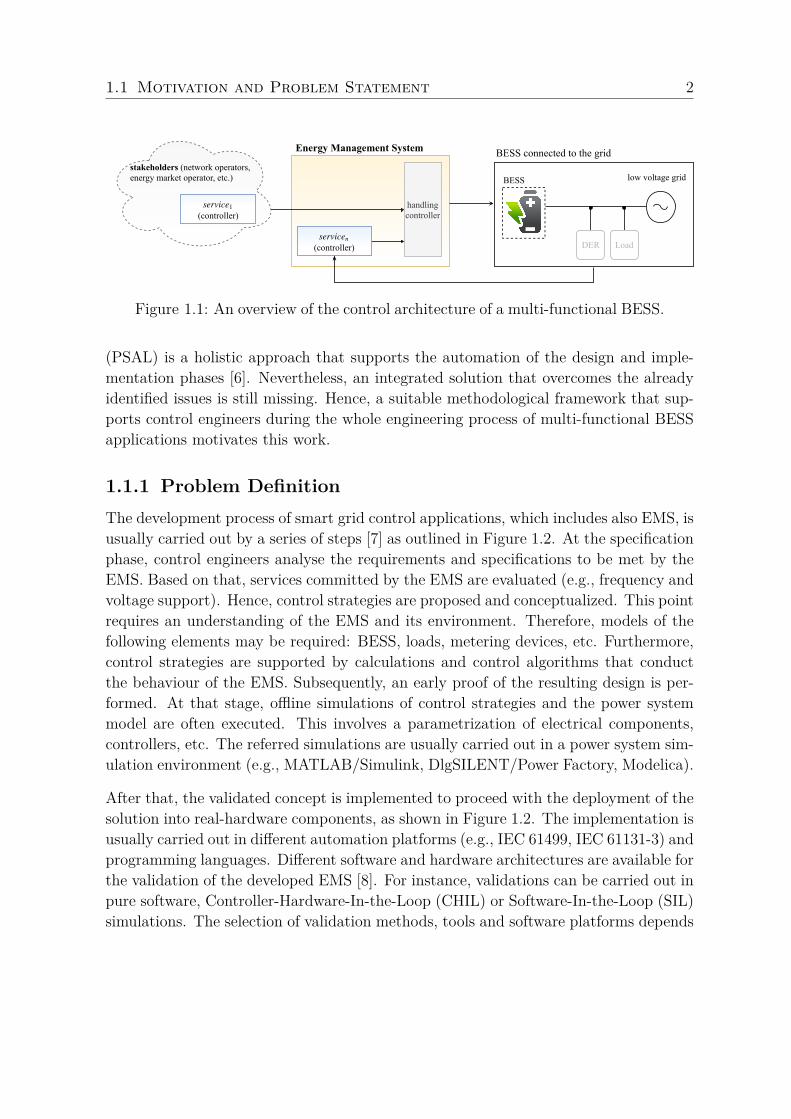
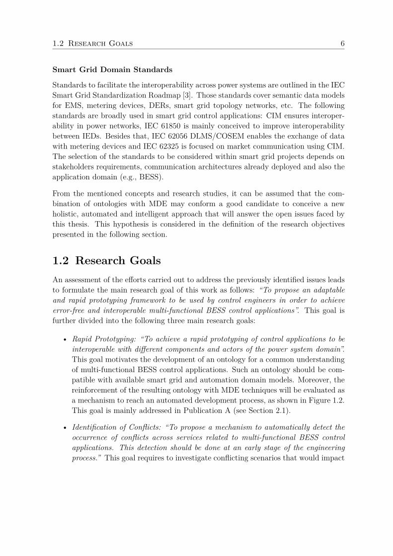
1.1 Motivation and Problem StatementCurrently, the main use of Battery Energy Storage Systems (BESS) is to support end-customers (industry/household) to reach self-consumption. However, in a near futureBESS will play an important role in the power grid since they could also contribute topower stability and quality [1]. Besides this, those BESS may also contribute to theimprovement of the hosting-capacity of the electricity grid and participate on powertrading, balancing market services, etc. As a consequence, a provision of cost-effectivesolutions for the end-user and other services to answer stakeholders demands wouldrequire the implementation of a multi-functional BESS. The aforementioned BESS ser-vices are mainly deployed within an Energy Management System (EMS). However,they could also coexist in other systems placed on the stakeholder side [2], as shown inFigure 1.1. By following that configuration, the EMS controls the storage system andshould be interoperable with a wide range of electrical components and systems such asIntelligent Electronic Devices (IEDs), Distributed Energy Resources (DERs), networkoperators, etc. Therefore, the interactions across different EMS related services shouldbe handled in order to avoid unattended conflicts that may harm the overall operationof the EMS. The control architecture of the referred EMS is depicted in Figure 1.1.
Given the above concerns, it can be concluded that the implementation of such EMS isa challenging task that involves conflict, interoperability and flexibility issues. Hence,the development process of those EMS should be addressed by modern engineeringapproaches. In fact, existing approaches support control engineers during the devel-opment of smart grid systems [3]. At the specification stage, IntelliGrid (IEC 62559)is recommended since it introduces a methodology to document smart grid Use Cases(UC) [4]. Smart Grid Architecture Model (SGAM) and System Modeling Language(SysML) are suggested at the design phase [5]. Power System Automation Language
1.1 Motivation and Problem Statement 2
(controller)service
n
BESS
handlingcontroller
BESS connected to the grid
low voltage grid
Energy Management System
stakeholders (network operators, energy market operator, etc.)
(controller)service1
DER Load
Figure 1.1: An overview of the control architecture of a multi-functional BESS.
(PSAL) is a holistic approach that supports the automation of the design and imple-mentation phases [6]. Nevertheless, an integrated solution that overcomes the alreadyidentified issues is still missing. Hence, a suitable methodological framework that sup-ports control engineers during the whole engineering process of multi-functional BESSapplications motivates this work.
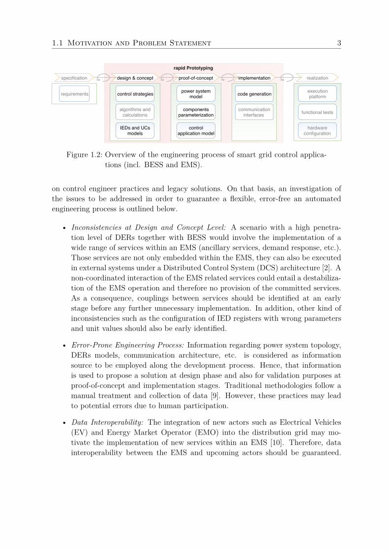
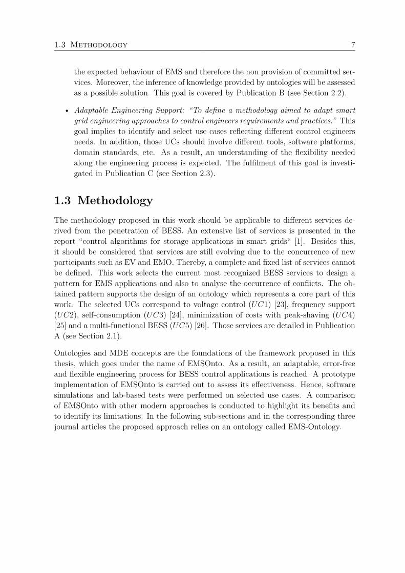
1.1.1 Problem DefinitionThe development process of smart grid control applications, which includes also EMS, isusually carried out by a series of steps [7] as outlined in Figure 1.2. At the specificationphase, control engineers analyse the requirements and specifications to be met by theEMS. Based on that, services committed by the EMS are evaluated (e.g., frequency andvoltage support). Hence, control strategies are proposed and conceptualized. This pointrequires an understanding of the EMS and its environment. Therefore, models of thefollowing elements may be required: BESS, loads, metering devices, etc. Furthermore,control strategies are supported by calculations and control algorithms that conductthe behaviour of the EMS. Subsequently, an early proof of the resulting design is per-formed. At that stage, offline simulations of control strategies and the power systemmodel are often executed. This involves a parametrization of electrical components,controllers, etc. The referred simulations are usually carried out in a power system sim-ulation environment (e.g., MATLAB/Simulink, DlgSILENT/Power Factory, Modelica).
After that, the validated concept is implemented to proceed with the deployment of thesolution into real-hardware components, as shown in Figure 1.2. The implementation isusually carried out in different automation platforms (e.g., IEC 61499, IEC 61131-3) andprogramming languages. Different software and hardware architectures are available forthe validation of the developed EMS [8]. For instance, validations can be carried out inpure software, Controller-Hardware-In-the-Loop (CHIL) or Software-In-the-Loop (SIL)simulations. The selection of validation methods, tools and software platforms depends
1.1 Motivation and Problem Statement 3
requirements control strategies
algorithms andcalculations
IEDs and UCsmodels
power systemmodel
componentsparameterization
controlapplication model
code generation
communicationinterfaces
execution platform
functional tests
hardwareconfiguration
specification proof-of-conceptdesign & concept
rapid Prototyping
implementation realization
Figure 1.2: Overview of the engineering process of smart grid control applica-tions (incl. BESS and EMS).
on control engineer practices and legacy solutions. On that basis, an investigation ofthe issues to be addressed in order to guarantee a flexible, error-free an automatedengineering process is outlined below.
• Inconsistencies at Design and Concept Level: A scenario with a high penetra-tion level of DERs together with BESS would involve the implementation of awide range of services within an EMS (ancillary services, demand response, etc.).Those services are not only embedded within the EMS, they can also be executedin external systems under a Distributed Control System (DCS) architecture [2]. Anon-coordinated interaction of the EMS related services could entail a destabiliza-tion of the EMS operation and therefore no provision of the committed services.As a consequence, couplings between services should be identified at an earlystage before any further unnecessary implementation. In addition, other kind ofinconsistencies such as the configuration of IED registers with wrong parametersand unit values should also be early identified.
• Error-Prone Engineering Process: Information regarding power system topology,DERs models, communication architecture, etc. is considered as informationsource to be employed along the development process. Hence, that informationis used to propose a solution at design phase and also for validation purposes atproof-of-concept and implementation stages. Traditional methodologies follow amanual treatment and collection of data [9]. However, these practices may leadto potential errors due to human participation.
• Data Interoperability: The integration of new actors such as Electrical Vehicles(EV) and Energy Market Operator (EMO) into the distribution grid may mo-tivate the implementation of new services within an EMS [10]. Therefore, datainteroperability between the EMS and upcoming actors should be guaranteed.
1.1 Motivation and Problem Statement 4
Nevertheless, traditional EMS control applications are not well prepared for arapid and easy integration of new components.
• Vendor-Independent Solution: EMS are implemented and validated according tospecific control engineers needs. Those needs are strictly aligned to usual prac-tices and legacy solutions. As a result, a wide range of emulators, tools, softwareplatforms, etc. may be used [11]. For instance: power system simulators (e.g.,DlgSILENT PowerFactory), communication tools (e.g., NS-3), automation tools(e.g., IEC 61131-3), co-simulation frameworks (e.g., mosaik), etc. However, avendor-independent solution that supports the EMS implementation and valida-tion under different software platforms and tools is still missing.
1.1.2 State-of-the-Art and Related WorkDevelopment Approaches
Existing engineering approaches support different stages of the engineering process ofEMS applications at different levels. A comparison of those approaches is carried outin [12] as part of this thesis. That study leads to conclude that a suitable approachthat addresses comprehensively the previously introduced open issues is still missing.An evaluation of benefits and limitations of the compared approaches is discussed below.
The IntelliGrid methodology introduces IEC 62559 use case templates to guide con-trol engineers during the specification of smart grid projects [13]. This involves thedefinition of business cases, smart grid use cases and requirements. As a consequence,IntelliGrid has been broadly employed at the specification stage. However, it is notrecommended for design purposes. Instead, the Unified Modeling Language (UML) isa widely used general-purpose language to support the specification and design of soft-ware applications in an object-oriented way [14]. UML offers visual diagrams to modelthe behaviour and structure of software solutions. Therefore, this modeling language isgetting more attention from engineers in charge of the design of smart grid solutions.UML is embedded in different tools that support corresponding code generation outof UML models. However this code is neither fully customized to engineer’s needs nororiented to EMS control applications. Alternatively, SGAM has been introduced bythe Smart Grid Coordination Group/Reference Architecture (SG-CG/RA) [3] to modelsmart grid use cases. SGAM suggests the following layers to map use cases within asmart grid model: communication, information, function, component and information.Thereby, a good overview of the smart grid UCs under study is achieved. An im-plementation of the SGAM methodology is reached by a UML-based Domain SpecificLanguage (DSL) called SGAM-Toolbox (SGAM-TB) [5]. This toolbox fosters the use of
1.1 Motivation and Problem Statement 5
SGAM in European and internationals power systems projects (FP7 ELECTRA IRP,FP7 DISCERN) [4]. Nevertheless, SGAM-TB does not propose a mechanism to checkthe consistency of information contained within SGAM models.
PSAL, a novel DSL for power systems was suggested at the design and implemen-tation phase [6]. This holistic approach provides many functionalities such as rapidprototyping of smart grid applications as well as an automatic generation of IEC 61850communication interfaces. It covers many aspects not considered by the previouslymentioned ones. However, since it is designed for generic smart grid applications, con-cepts for EMS and BESS domains are not really addressed in a comprehensive manner.Besides of that, detection of inconsistencies within the planned design is not supported.Laboratory experiments demonstrated that PSAL is compatible with specification ap-proaches (SGAM), a communication information model (IEC 61850) and an automationapproach for distributed control systems (IEC 61499) [15]. However, the adaptabilityof PSAL to different environments is not yet addressed.
Rapid Prototyping
Ontologies support the alignment of related domain models as well as the integrationof knowledge [16]. In this domain, an ontology matching process is implemented toachieve an alignment of two broadly recognized power utility standards Common In-formation Model (CIM) and IEC 61850 [17]. Besides this, Dubinin et al. [18] employsan ontology-driven approach to generate IEC 61499 applications from an ontologicaldescription of a control system. Similar results where transformation of domain modelstakes place can also be achieved by applying Model Driven Engineering (MDE) con-cepts. MDE defines mechanisms to achieve a partial automation of the engineeringprocess [19]. An implementation of MDE practices is introduced by the Object Man-agement Group (OMG) under the name of Model Driven Architecture (MDA).
MDA techniques are employed within PSAL for an automatic generation of executablecode and also communication interfaces from SGAMUCs specifications [6]. Besides this,Andrén et al. [20] supports the generation of IEC 61499 applications out of IEC 61850descriptions. Another research area to consider is the use of ontologies to infer in-formation from explicit knowledge by means of reasoning mechanisms. This featureis employed in a building energy management system context to reach an automaticmatching of services and communication technologies [21]. Besides this, a diagnostic ofelectrical faults in power transformers is carried out by ontologies in combination withfuzzy logic theory [22]. Even if none of the referred studies is multi-functional BESSoriented, they motivate the use of ontologies for inconsistencies detection.
1.2 Research Goals 6
Smart Grid Domain Standards
Standards to facilitate the interoperability across power systems are outlined in the IECSmart Grid Standardization Roadmap [3]. Those standards cover semantic data modelsfor EMS, metering devices, DERs, smart grid topology networks, etc. The followingstandards are broadly used in smart grid control applications: CIM ensures interoper-ability in power networks, IEC 61850 is mainly conceived to improve interoperabilitybetween IEDs. Besides that, IEC 62056 DLMS/COSEM enables the exchange of datawith metering devices and IEC 62325 is focused on market communication using CIM.The selection of the standards to be considered within smart grid projects depends onstakeholders requirements, communication architectures already deployed and also theapplication domain (e.g., BESS).
From the mentioned concepts and research studies, it can be assumed that the com-bination of ontologies with MDE may conform a good candidate to conceive a newholistic, automated and intelligent approach that will answer the open issues faced bythis thesis. This hypothesis is considered in the definition of the research objectivespresented in the following section.
1.2 Research GoalsAn assessment of the efforts carried out to address the previously identified issues leadsto formulate the main research goal of this work as follows: “To propose an adaptableand rapid prototyping framework to be used by control engineers in order to achieveerror-free and interoperable multi-functional BESS control applications”. This goal isfurther divided into the following three main research goals:
• Rapid Prototyping: “To achieve a rapid prototyping of control applications to beinteroperable with different components and actors of the power system domain”.This goal motivates the development of an ontology for a common understandingof multi-functional BESS control applications. Such an ontology should be com-patible with available smart grid and automation domain models. Moreover, thereinforcement of the resulting ontology with MDE techniques will be evaluated asa mechanism to reach an automated development process, as shown in Figure 1.2.This goal is mainly addressed in Publication A (see Section 2.1).
• Identification of Conflicts: “To propose a mechanism to automatically detect theoccurrence of conflicts across services related to multi-functional BESS controlapplications. This detection should be done at an early stage of the engineeringprocess.” This goal requires to investigate conflicting scenarios that would impact
1.3 Methodology 7
the expected behaviour of EMS and therefore the non provision of committed ser-vices. Moreover, the inference of knowledge provided by ontologies will be assessedas a possible solution. This goal is covered by Publication B (see Section 2.2).
• Adaptable Engineering Support: “To define a methodology aimed to adapt smartgrid engineering approaches to control engineers requirements and practices.” Thisgoal implies to identify and select use cases reflecting different control engineersneeds. In addition, those UCs should involve different tools, software platforms,domain standards, etc. As a result, an understanding of the flexibility neededalong the engineering process is expected. The fulfilment of this goal is investi-gated in Publication C (see Section 2.3).
1.3 MethodologyThe methodology proposed in this work should be applicable to different services de-rived from the penetration of BESS. An extensive list of services is presented in thereport “control algorithms for storage applications in smart grids“ [1]. Besides this,it should be considered that services are still evolving due to the concurrence of newparticipants such as EV and EMO. Thereby, a complete and fixed list of services cannotbe defined. This work selects the current most recognized BESS services to design apattern for EMS applications and also to analyse the occurrence of conflicts. The ob-tained pattern supports the design of an ontology which represents a core part of thiswork. The selected UCs correspond to voltage control (UC1) [23], frequency support(UC2), self-consumption (UC3) [24], minimization of costs with peak-shaving (UC4)[25] and a multi-functional BESS (UC5) [26]. Those services are detailed in PublicationA (see Section 2.1).
Ontologies and MDE concepts are the foundations of the framework proposed in thisthesis, which goes under the name of EMSOnto. As a result, an adaptable, error-freeand flexible engineering process for BESS control applications is reached. A prototypeimplementation of EMSOnto is carried out to assess its effectiveness. Hence, softwaresimulations and lab-based tests were performed on selected use cases. A comparisonof EMSOnto with other modern approaches is conducted to highlight its benefits andto identify its limitations. In the following sub-sections and in the corresponding threejournal articles the proposed approach relies on an ontology called EMS-Ontology.
1.3 Methodology 8
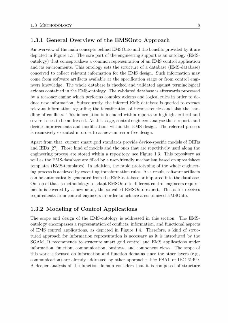
1.3.1 General Overview of the EMSOnto ApproachAn overview of the main concepts behind EMSOnto and the benefits provided by it aredepicted in Figure 1.3. The core part of the engineering support is an ontology (EMS-ontology) that conceptualizes a common representation of an EMS control applicationand its environments. This ontology sets the structure of a database (EMS-database)conceived to collect relevant information for the EMS design. Such information maycome from software artifacts available at the specification stage or from control engi-neers knowledge. The whole database is checked and validated against terminologicalaxioms contained in the EMS-ontology. The validated database is afterwards processedby a reasoner engine which performs complex axioms and logical rules in order to de-duce new information. Subsequently, the inferred EMS-database is queried to extractrelevant information regarding the identification of inconsistencies and also the han-dling of conflicts. This information is included within reports to highlight critical andsevere issues to be addressed. At this stage, control engineers analyse those reports anddecide improvements and modifications within the EMS design. The referred processis recursively executed in order to achieve an error-free design.
Apart from that, current smart grid standards provide device-specific models of DERsand IEDs [27]. Those kind of models and the ones that are repetitively used along theengineering process are stored within a repository, see Figure 1.3. This repository aswell as the EMS-database are filled by a user-friendly mechanism based on spreadsheettemplates (EMS-templates). In addition, the rapid prototyping of the whole engineer-ing process is achieved by executing transformation rules. As a result, software artifactscan be automatically generated from the EMS-database or imported into the database.On top of that, a methodology to adapt EMSOnto to different control engineers require-ments is covered by a new actor, the so called EMSOnto expert. This actor receivesrequirements from control engineers in order to achieve a customized EMSOnto.
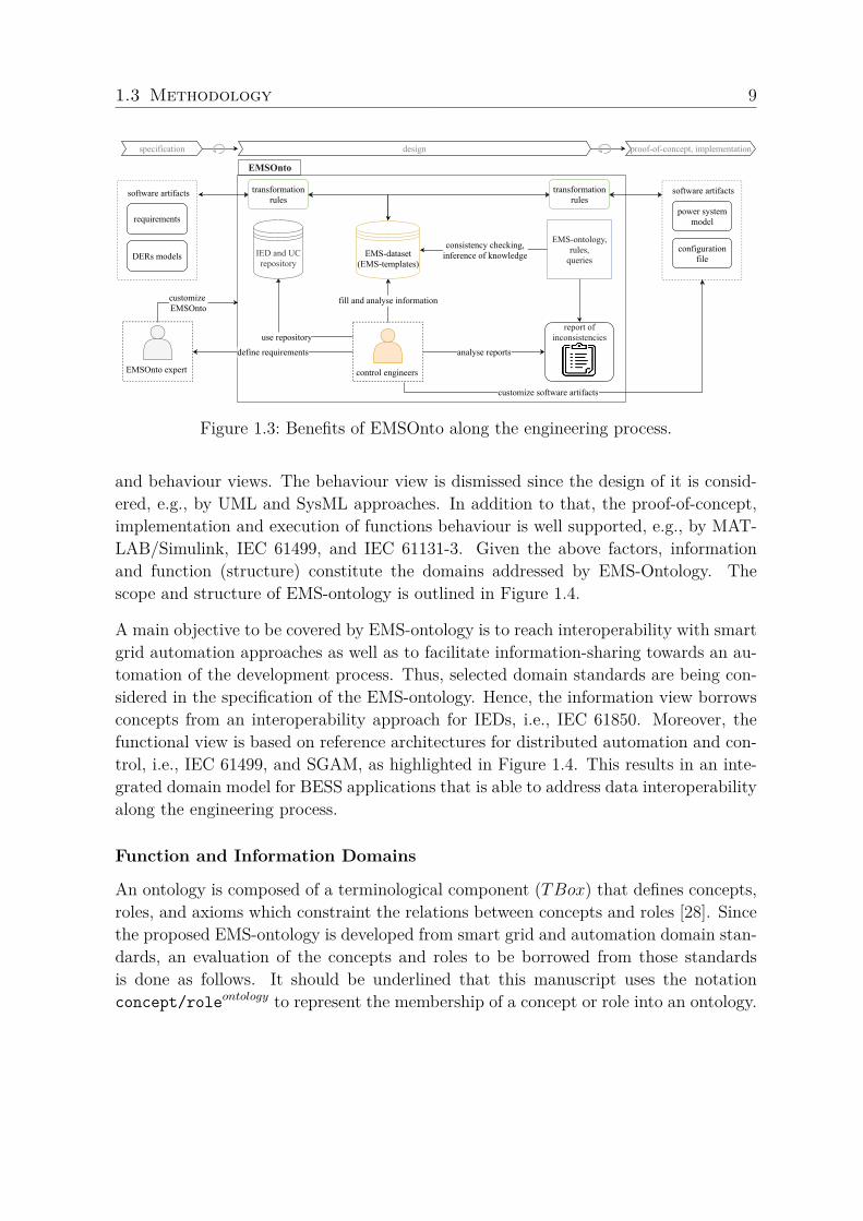
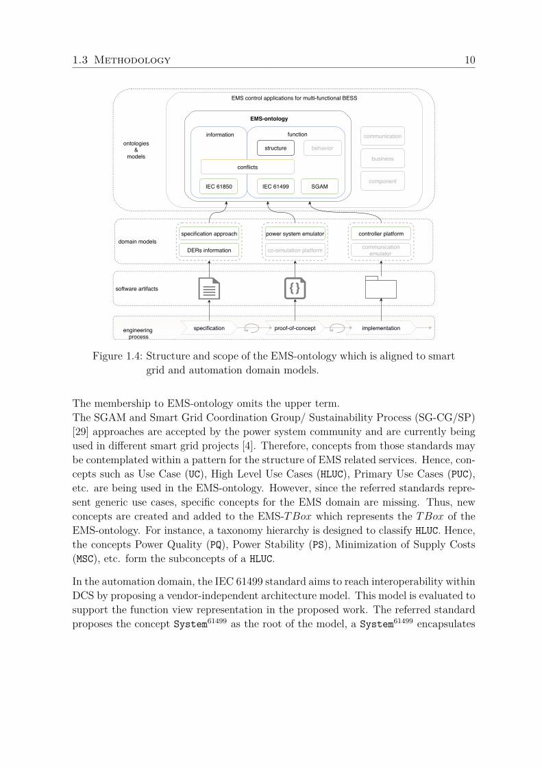
1.3.2 Modeling of Control ApplicationsThe scope and design of the EMS-ontology is addressed in this section. The EMS-ontology encompasses a representation of conflicts, information, and functional aspectsof EMS control applications, as depicted in Figure 1.4. Therefore, a kind of struc-tured approach for information representation is necessary as it is introduced by theSGAM. It recommends to structure smart grid control and EMS applications underinformation, function, communication, business, and component views. The scope ofthis work is focused on information and function domains since the other layers (e.g.,communication) are already addressed by other approaches like PSAL or IEC 61499.A deeper analysis of the function domain considers that it is composed of structure
1.3 Methodology 9
consistency checking, inference of knowledge
EMSontology, rules, queries
report ofinconsistencies
transformation rules
transformation rules
control engineers
analyse reports
fill and analyse information
use repository
define requirements
IED and UC repository
EMSOnto expert
customize EMSOnto
specification design proofofconcept, implementation
EMSOnto
power systemmodel
configurationfile
software artifacts
requirements
DERs models
software artifacts
EMSdataset (EMStemplates)
customize software artifacts
Figure 1.3: Benefits of EMSOnto along the engineering process.
and behaviour views. The behaviour view is dismissed since the design of it is consid-ered, e.g., by UML and SysML approaches. In addition to that, the proof-of-concept,implementation and execution of functions behaviour is well supported, e.g., by MAT-LAB/Simulink, IEC 61499, and IEC 61131-3. Given the above factors, informationand function (structure) constitute the domains addressed by EMS-Ontology. Thescope and structure of EMS-ontology is outlined in Figure 1.4.
A main objective to be covered by EMS-ontology is to reach interoperability with smartgrid automation approaches as well as to facilitate information-sharing towards an au-tomation of the development process. Thus, selected domain standards are being con-sidered in the specification of the EMS-ontology. Hence, the information view borrowsconcepts from an interoperability approach for IEDs, i.e., IEC 61850. Moreover, thefunctional view is based on reference architectures for distributed automation and con-trol, i.e., IEC 61499, and SGAM, as highlighted in Figure 1.4. This results in an inte-grated domain model for BESS applications that is able to address data interoperabilityalong the engineering process.
Function and Information Domains
An ontology is composed of a terminological component (TBox) that defines concepts,roles, and axioms which constraint the relations between concepts and roles [28]. Sincethe proposed EMS-ontology is developed from smart grid and automation domain stan-dards, an evaluation of the concepts and roles to be borrowed from those standardsis done as follows. It should be underlined that this manuscript uses the notationconcept/roleontology to represent the membership of a concept or role into an ontology.
1.3 Methodology 10
structure behavior
information function
conflicts
specification approach power system emulator controller platform
communication
business
component
software artifacts
EMS control applications for multi-functional BESS
ontologies &
models
specification proof-of-concept implementationengineering process
communicationemulator co-simulation platform DERs information
EMS-ontology
IEC 61499IEC 61850 SGAM
domain models
Figure 1.4: Structure and scope of the EMS-ontology which is aligned to smartgrid and automation domain models.
The membership to EMS-ontology omits the upper term.The SGAM and Smart Grid Coordination Group/ Sustainability Process (SG-CG/SP)[29] approaches are accepted by the power system community and are currently beingused in different smart grid projects [4]. Therefore, concepts from those standards maybe contemplated within a pattern for the structure of EMS related services. Hence, con-cepts such as Use Case (UC), High Level Use Cases (HLUC), Primary Use Cases (PUC),etc. are being used in the EMS-ontology. However, since the referred standards repre-sent generic use cases, specific concepts for the EMS domain are missing. Thus, newconcepts are created and added to the EMS-TBox which represents the TBox of theEMS-ontology. For instance, a taxonomy hierarchy is designed to classify HLUC. Hence,the concepts Power Quality (PQ), Power Stability (PS), Minimization of Supply Costs(MSC), etc. form the subconcepts of a HLUC.
In the automation domain, the IEC 61499 standard aims to reach interoperability withinDCS by proposing a vendor-independent architecture model. This model is evaluated tosupport the function view representation in the proposed work. The referred standardproposes the concept System61499 as the root of the model, a System61499 encapsulates
1.3 Methodology 11
Applications61499 conformed by a network of functions blocs (FB61499) that exchangedata flows (dataConnections61499) across them. Hence, the following concepts areadded to the EMS-TBox: System, Application, InformationFlow, etc.
The resulting EMS-ontology is complemented with a representation of the informa-tion view which may be supported by a wide range of information models availablein the smart grid domain. This work considers IEC 61850 as baseline model sinceit defines IEDs and control function models relevant for multi-functional BESS. SinceIEC 61850-7-3 proposes data models for run-time signals, the following concepts aremade available to classify information exchanged between IEDs: AnalogSettings61850,StatusSettings61850, ControlableStatusInfo61850, etc. Those concepts motivate thecreation of Control, Status, Setpoint, etc. The format of the exchanged data com-prises the following concepts: AnalogValue61850, BOOLEAN61850, STRING 25561850, amongothers. Such representation leads to create the concepts Numeric, Binary and Char.Besides that, a taxonomy for parameters and dynamic variables is also developed toachieve parametrization of components such as controllers, IED, DERs. Therefore, P,Pmax, SettlingTime concepts among others are created. P represents active power,Pmax models maximum active power and SettlingTime is the settling time to be con-sidered by a controller. An exhaustive list of concepts, roles and axioms within theEMS-TBox is presented in Publication A (see Section 2.1).
Conflicts within UCs
Until now the developed ontology cannot detect any service interactions that may harmthe correct operation of EMS control applications. This point is addressed by extendingthe EMS-ontology as shown below.
The identification of conflicting scenarios within multi-functional BESS control applica-tions is carried out in this work. As a result, a classification of conflicts in six categories(CI − CV I) is achieved. Such classification is reflected in an extended version of EMS-ontology. For instance, the conflict CI considers at least two different PUCs offered byan EMS. The aim of each PUC is to implement control goals that manipulate states ofthe system under study (e.g., BESS connected to a grid). The conflict CI arises when acontrol goal is affected simultaneously by at least two different PUC. For instance, a PUCseeks to minimize energy costs to be paid by end-users. Hence, the control goal behindit manipulates the power injected into the grid (Pgrid) in order to maintain the value tozero. At the same time, another PUC requires to manipulate the value of Pgrid to supportgrid frequency fluctuations. As a consequence, the referred control goals are in conflictdue to a simultaneous manipulation of Pgrid. An abstract representation of conflict CI
requires to create new concepts and roles: ControlGoal, Conflict, Manipulate, etc.
1.3 Methodology 12
Besides the identification of conflicts, the handling of them is also considered within theEMS-ontology. Since handling methods requires to carry out algorithms. EMS-ontologymodels the dataset used by a software program destined to resolve conflicts. For thehandling of conflict CI , the setting up of priorities for each PUC is suggested. This meansthat only the PUC with the highest priority will operate, the others PUCs will be disable.To achieve this, definition of new concepts are also required (e.g., Priority and Ena).Priority represents the priority defined at PUC level and Ena holds the informationregarding PUC activation. Concepts and roles of EMS-ontology are now established,however the expressivity of the ontology should be improved in order to achieve thededuction of new information and therefore the identification of inconsistencies. Thistopic is addressed in the following paragraph.
1.3.3 Inconsistencies IdentificationOne main objective of the EMS-ontology is to support the identification of inconsisten-cies. This is planned to be achieved by the inference of knowledge, an important featureprovided by ontologies. Since axioms and rules are required for an efficient inferenceprocedure, the achieved ontology is complemented with axioms within the EMS-TBox
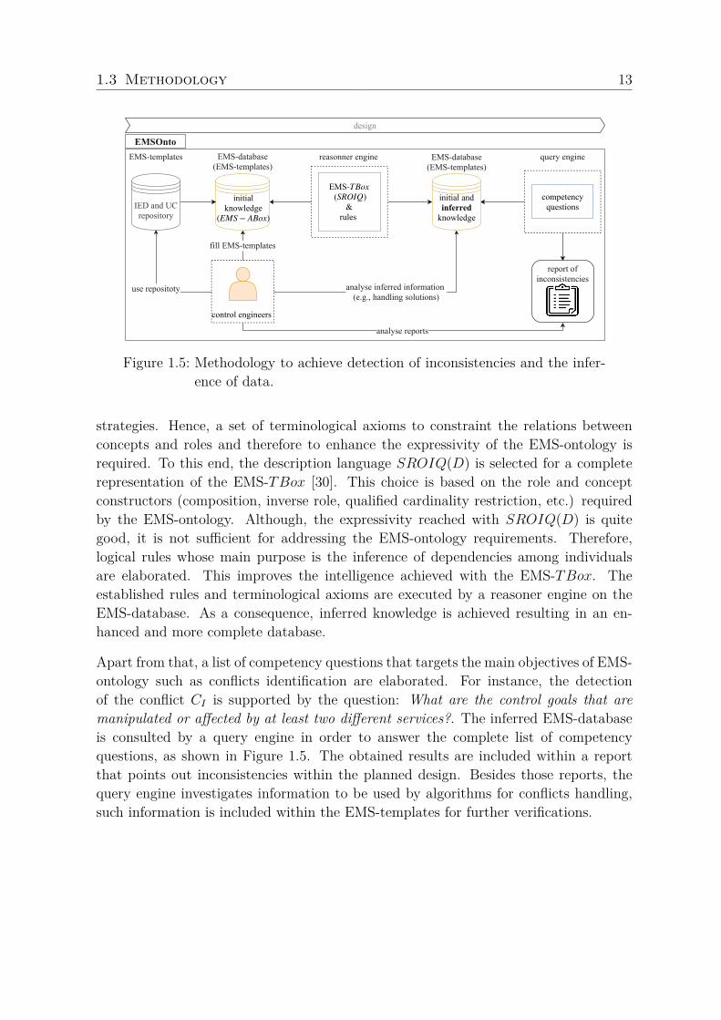
as well as logical rules. Besides this, another important point to be considered is the as-sertional component of the EMS-ontology (EMS-ABox) which states the participationof individuals in concepts and roles. This means that EMS-ABox contains assertionsabout the EMS control application to be designed. Such assertions are given by controlengineers at the beginning of the design process, see Figure 1.5. In order to supportthat task, the use of spreadsheet templates (i.e., EMS-templates) are suggested. Oncethis task is completed, a reasoner engine executes the established axioms and rules onthe EMS-ABox in order to come up with new assertions. The enhanced EMS-Abox isqueried to detect inconsistencies as well as to generate additional information for theEMS design (e.g., data for the handling of conflicts). The inconsistencies detected areregistered on reports, in the meanwhile relevant inferred data is added to the EMS-templates. This data may correspond to solutions for the identified conflicts as well asto other kind of inferences to be customized by control engineers. All this informationis handed over to control engineers, who decide modifications and improvements withinthe EMS design. An overview of the referred process is depicted in Figure 1.5.
Axioms, Rules and Queries
The vocabulary conformed by concepts, roles and individuals established within EMS-ontology is not enough to represent the knowledge around the interactions of control
1.3 Methodology 13
analyse reports
EMS ( )
& rules
TBox
SROIQ
reasonner engine
control engineers
fill EMStemplates
competencyquestions
report ofinconsistencies
analyse inferred information (e.g., handling solutions)
query engine
use repositoty
EMSOnto
design
initialknowledge
(EMS − ABox)
initial and inferred knowledge
EMSdatabase (EMStemplates)
IED and UC repository
EMSdatabase (EMStemplates)
EMStemplates
Figure 1.5: Methodology to achieve detection of inconsistencies and the infer-ence of data.
strategies. Hence, a set of terminological axioms to constraint the relations betweenconcepts and roles and therefore to enhance the expressivity of the EMS-ontology isrequired. To this end, the description language SROIQ(D) is selected for a completerepresentation of the EMS-TBox [30]. This choice is based on the role and conceptconstructors (composition, inverse role, qualified cardinality restriction, etc.) requiredby the EMS-ontology. Although, the expressivity reached with SROIQ(D) is quitegood, it is not sufficient for addressing the EMS-ontology requirements. Therefore,logical rules whose main purpose is the inference of dependencies among individualsare elaborated. This improves the intelligence achieved with the EMS-TBox. Theestablished rules and terminological axioms are executed by a reasoner engine on theEMS-database. As a consequence, inferred knowledge is achieved resulting in an en-hanced and more complete database.
Apart from that, a list of competency questions that targets the main objectives of EMS-ontology such as conflicts identification are elaborated. For instance, the detectionof the conflict CI is supported by the question: What are the control goals that aremanipulated or affected by at least two different services?. The inferred EMS-databaseis consulted by a query engine in order to answer the complete list of competencyquestions, as shown in Figure 1.5. The obtained results are included within a reportthat points out inconsistencies within the planned design. Besides those reports, thequery engine investigates information to be used by algorithms for conflicts handling,such information is included within the EMS-templates for further verifications.
1.3 Methodology 14
Gathering EMS knowledge
It is worthy of note that the effectiveness of EMSOnto highly depends on the quantityand quality of the collected informations (EMS-ABox). Hence, the following require-ments have been set as guidelines: (i) constraint the insertion of data, (ii) gathering ofunlimited amount of data, (iii) user-friendly and easy to handle. Based on the statedrequirements, spreadsheets templates having as headlines the names of concepts androles defined in the EMS-TBox are elaborated and proposed in this work under thename of EMS-templates. Those templates implement the constraints between conceptsand roles already defined in the terminological axioms of the EMS-ontology. This isachieved by using filtering, comparison, and formatting functions, among others, whichare available in a large set of tools used to process tabular formats (e.g., OpenOffice,Microsoft Excel). Furthermore, since control engineers are usually familiar with spread-sheet formats, an extensive training to get familiar with the proposed methodology isnot needed. Apart from that, because of their tabular format, an easy and unlimitedcollection of data is guarantee. In contrast, this is not facilitated by any of the exist-ing engineering approaches (e.g., IntelliGrid, PSAL). The explained facts motivate thesetting up of a repository, based on EMS-templates, which stores IED and UC modelsto be reused through the development process.
1.3.4 Model and Code GenerationOne goal of this work is the reuse of information along the whole engineering processin an automated way to achieve a rapid prototyping of EMS control applications. Asolution to that is discussed in the following.
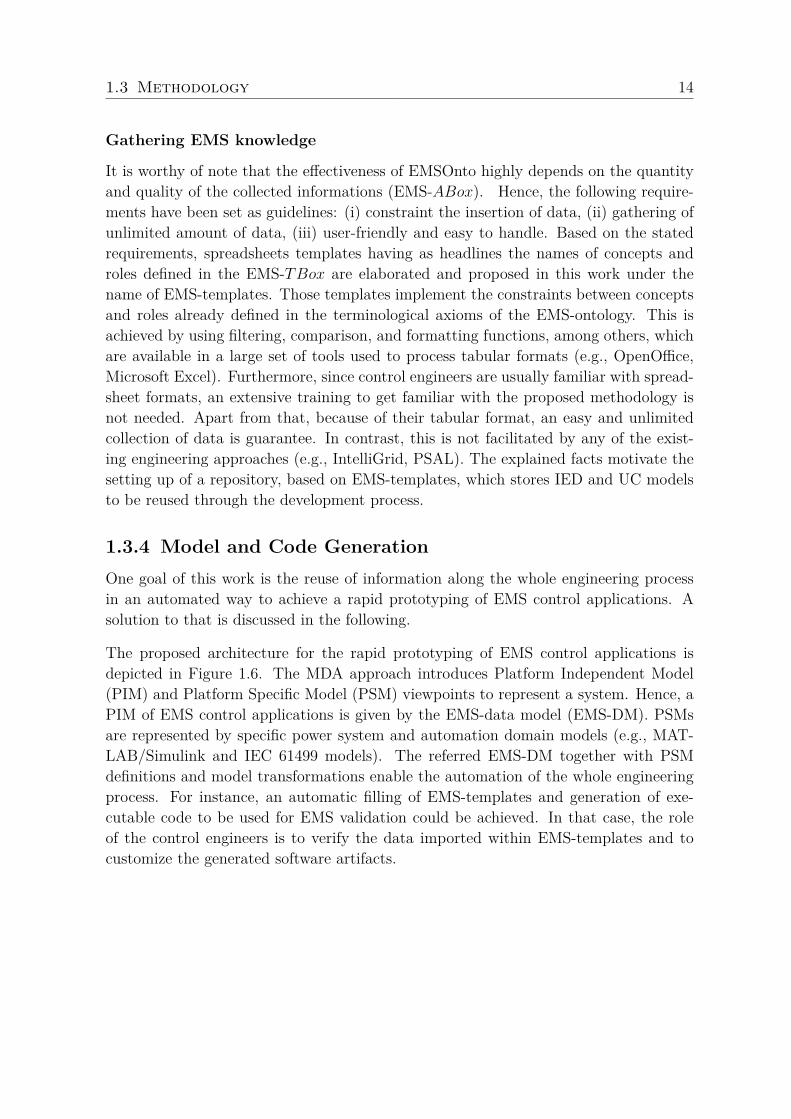
The proposed architecture for the rapid prototyping of EMS control applications isdepicted in Figure 1.6. The MDA approach introduces Platform Independent Model(PIM) and Platform Specific Model (PSM) viewpoints to represent a system. Hence, aPIM of EMS control applications is given by the EMS-data model (EMS-DM). PSMsare represented by specific power system and automation domain models (e.g., MAT-LAB/Simulink and IEC 61499 models). The referred EMS-DM together with PSMdefinitions and model transformations enable the automation of the whole engineeringprocess. For instance, an automatic filling of EMS-templates and generation of exe-cutable code to be used for EMS validation could be achieved. In that case, the roleof the control engineers is to verify the data imported within EMS-templates and tocustomize the generated software artifacts.
1.3 Methodology 15
conforms to conforms to domain model
(e.g., Power systememulator model)
PSM PSM
EMSOnto
specification design proofofconcept, implementation
EMSontology EMSDM
PIM
domain model (e.g., specificationapproach model)
control engineers customize software artifacts
softwareartifacts
softwareartifacts
M2M M2M, M2T
(e.g., IntelliGrid templates,
SGAM models)
(e.g., IEC 61499models)
EMSdatabase (EMStemplates)
verify data generated
Figure 1.6: Software architecture solution to automate the EMS engineeringprocess based on MDE and ontology concepts.
From EMS-ontology to EMS-DM
The MDA engineering approach is supported by OMG specifications such as UML andSysML. In this sense, different researches suggest the use of UML to integrate MDA withontological engineering [31]. Therefore, this work designs a UML class representationderived from the concepts and roles established in the EMS-TBox. Since the referredontology is expressed by the SROIQ(D) description language, a mapping betweenSROIQ elements and UML components is proposed. Hence, the following mappingsare performed: conceptSROIQ into classUML, roleSROIQ into associationUML, etc. Theimplementation of the established mappings results in a UML class representation ofEMS-ontology called EMS-DM, which corresponds to the PIM model of the MDAapproach. It is worth to mention that although the resulting UML model is fullyaligned with the EMS-ontology, it does not represents all the knowledge abstractedby the EMS-ontology. The referred mappings together with the resulting UML model(EMS-DM) are detailed in Publication C (see Section 2.3).
Model Transformations
Divers software artifacts involved along the engineering process should be used in anautomated manner towards a rapid development of BESS applications. This point isaddressed by MDA techniques which are based on the setting up of PIMs, PSMs andtransformation rules. Hence, M2M transformations between PIMs and PSMs are per-formed as well as M2T transformations to generate code from models, see Figure 1.6.In order to set up a MDA solution, an identification of data manipulated along thedevelopment process is required. This data belong to a wide range of software arti-
1.3 Methodology 16
facts, for instance: specification documents (IEC 62559 UC templates), configurationfiles (IEC 61850 configuration files), controllers code (IEC 61499 applications), powersystem models (MATLAB/Simulink model), etc.
Subsequently, a PSM of the referred data is developed (e.g., SGAMmodel). Consideringthat the PIM is represented by the EMS-DM, mappings are established across the EMS-DM and PSMs. The main challenge here is to achieve an EMS-DM to be interoperablewith different PSMs of the power system and automation domain (e.g., IEC 61850,IEC 61499 models). Since the EMS-ontology was conceived under IEC 61850, IEC 61499and SGAM models, the EMS-DM is also compatible with those standards. Standardsnot considered may entail an extension of the EMS-ontology and therefore the EMS-DM. As a final step, the achievement of executable code and text is reached from theEMS-DM or the PSMs, as depicted in Figure 1.6.
1.3.5 Adaptation of the Engineering Support FrameworkThe features offered by EMSOnto should be customizable to different practices andneeds of control engineers. Therefore, an analysis and classification of control engineersrequirements is carried out. As a result, the following requirement types were identified:to provide flexibility for the generation of models and code, to benefit from a wide rangeof information sources available at the design stage and finally to infer new informationbesides conflicts detection. Those requirements are addressed by a list of procedures andrules to be followed by a new actor, the so called EMSOnto expert. Hence, suggestionsto upgrade the concepts, roles and axioms of EMS-ontology as well as the process bywhich information is inferred are made. Moreover, other tasks encompassing MDEpractices are also established. The referred list of procedures is detailed and validatedon an EMS use case example in Publication C (see Section 2.3).
1.3.6 Proof-of-Concept EvaluationThe research goals introduced in Section 1.2 were addressed in this work by a mod-ern engineering framework (i.e., EMSOnto). A prototypical implementation of it wascarried out mainly by using semantic web technologies and the Eclipse Modeling Frame-work (EMF), a tool that implements the key aspects of MDA. This prototype enablesthe test of EMSOnto on different use cases scenarios. Hence, the benefits claimedby EMSOnto have been assessed on BESS control applications by pure software sim-ulations and also by selected laboratory experiments. Such control applications arerepresented by a Smart Low Voltage Grid Controller (SLVGC) and a Customer En-ergy Management System (CEMS). The SLVGC controller executes self-consumption,
1.3 Methodology 17
market services and voltage control, while the CEMS embeds frequency support andself-consumption services.
The effectiveness of EMSOnto with regards to detection of conflicts is measured byF − measure which is used in search and document classification areas to evaluate al-gorithms and systems performance [32]. The referred value is calculated from precision
and recall measures, precision is the fraction of corrected identified conflicts out of thetotal number of identified conflicts, while recall represents the fraction of correctedidentified conflicts out of the total number of existing conflicts. By executing inferencesprocedures on the SLVGC controller, 4 conflicts were detected, from there only 3 werecorrect and 1 conflict was not detected. This shows that the inference procedures forconflicts identification have a good performance for that particular test. That resultcould not be evaluated with respect to results from other engineering approaches sincecomparable approaches are missing. Moreover, it is clear that further tests need to bedone to better estimate the performance of the proposed solution.
The rapid prototyping feature was evaluated by identifying the tasks automated alongthe whole engineering process. An overall picture of the automated tasks helps toevaluate the reduced amount of manual work in favour of control engineers. For thisevaluation, the CEMS was implemented by using EMSOnto. As a result, the automatedtasks correspond to an automatic generation of code and models for validation purposes,integration of information sources within a database, etc. Nevertheless, fully automatedtasks were not achieve since control engineers intervention was necessary to integrateaspects not considered by EMSOnto such as control application behaviour and alsothe implementation of communication interfaces, as shown in Figure 1.6. In otherwords, code generated needed to be refined and tailored to achieve operational softwareartifacts. Apart from that, this work addresses the goal regarding adaptability of theengineering process by suggesting a procedure list to be performed by the EMSOntoexpert. This procedure is tested on a new use case containing a wide range of controlengineers requirements set to enhance and make easier the CEMS engineering process.As a result, new smart grid standards, software artifacts and tools were encompassedby EMSOnto. Moreover, not only conflicts issues were identified but also other kindof inconsistencies. The implementation of that use case helps to identify future needssuch as the extension of the EMS-ontology with temporal logic, the use of reverseengineering techniques, the consideration of communication and component domains,among others. Future work contemplates to reach a full implementation of EMSOntoin order to test the support framework on different configurations of multi-functionalBESS control applications. This would lead to better estimate the whole performanceof EMSOnto as well as its limitations and further improvements.
1.4 Summary of Scientific Publications 18
1.4 Summary of Scientific PublicationsIn Publication A (see Section 2.1), a framework for the rapid prototyping of multi-functional BESS applications is achieved. The referred framework is meant to supportcontrol engineers during the whole development process. The cornerstone of this ap-proach is an ontology (EMS-ontology) that reflects a common understanding of informa-tion and function domains of smart grid applications. This ontology is built from smartgrid standards and is supported by MDE techniques to achieve a semi-automated engi-neering process. Benefits from the proposed framework include a BESS control appli-cation design compatible with broadly recognized smart grid models such as IEC 61850and SGAM. In addition, software artifacts employed at the proof-of-concept stage canbe semi-automatic generated. The population of EMS-ontology requires the collectionof data from control engineers in order to achieve the referred benefits. This point isaddressed by a user-friendly mechanism based on spreadsheet templates. The proposedframework is implemented in a prototype to tests its efficiency and performance. Inthat context, software simulations and laboratory experiments in a hardware-in-the-loop basis were performed on a selected use case example.
In Publication B (see Section 2.2), a framework for the detection and handling ofcontrol conflicts due to the overlapping of use cases within a multi-functional BESSapplication is introduced. Therefore, control schemes of those use cases were analysedwith the aim to identify conflicting scenarios that would harm the BESS control ap-plication operation. As a result, a classification of conflicts scenarios and subsequentlya pattern were identified. This supported the development of an ontology that bymeans of inferences procedures identifies the referred conflicts. That ontology is re-sulted from an extension of the one achieved in Publication A (see Section 2.1), the socalled EMS-ontology. Apart from that, conflicts resolution mechanisms were also stud-ied and adopted within the ontology. Pure software simulations within a power systemsimulator were performed to demonstrate the effectiveness of the proposed solution.
In Publication C (see Section 2.3), a methodology to adapt current engineering ap-proaches to control engineers needs by means of ontologies and MDE basis is proposed.Therefore, engineers needs aiming to automate and guide their tasks along the engineer-ing process are investigated. Those requirements are addressed by a list of proceduresthat intends to embrace different smart grid standards, software artifacts and toolsinvolved within the development process. In addition, different kind of inconsistenciesat the design level were also addressed. The usability of the proposed methodology istested on the framework resulted from Publication A (see Section 2.1). Hence, a UCrelated to the integration of BESS into the distribution grid was implemented.
1.5 Scientific Contributions of this Work 19
1.5 Scientific Contributions of this WorkThe main scientific contribution of this work is an engineering support framework whereontologies and MDE techniques are combined to offer an error-free, rapid and flexibleimplementation of multi-functional BESS control applications. The achieved engineer-ing support can also be applied to other types of smart grid control applications pro-viding a proper tool for the massive roll-out of new solutions and components. In orderto test the performance of the referred approach a prototypical implementation of it isdeveloped. The contributions of this work are summarized as follows:
• Engineering support framework, with a firm MDE and ontologies backbone, forthe rapid prototyping of BESS applications.– An ontology representing functional and information aspects of multi-use
BESS control applications, as reflected in Figure 1.4.– A vendor-independent solution to increase reusability and consistency of the
information used across the EMS engineering process.– Spreadsheet templates to easily collect and treat relevant information for the
design of BESS control applications.– An architecture for a flexible generation of code and models based on MDE an
ontologies to be applied in the power system domain, as shown in Figure 1.6.– A lab-based validated engineering framework.
• Inference procedures to identify and handle conflicts within BESS applications.– A classification of conflicts arisen from the interaction of services embedded
within multi-functional BESS control applications.– An ontology that supports the identification and handling of conflicts.– Logical rules, terminological axioms and queries that support the inference
of information.– A validated approach through power system simulations.
• Procedures and rules for adapting EMSOnto to new requirements and domains.– The proposed methodology can also be applied to other existing engineering
approaches of the smart grid domain (e.g., PSAL).– EMSOnto is now able to encompass different smart grid standards, tools and
software artifacts.– A validated procedure through the implementation of a control application
for BESS.
1.6 Concluding Remarks 20
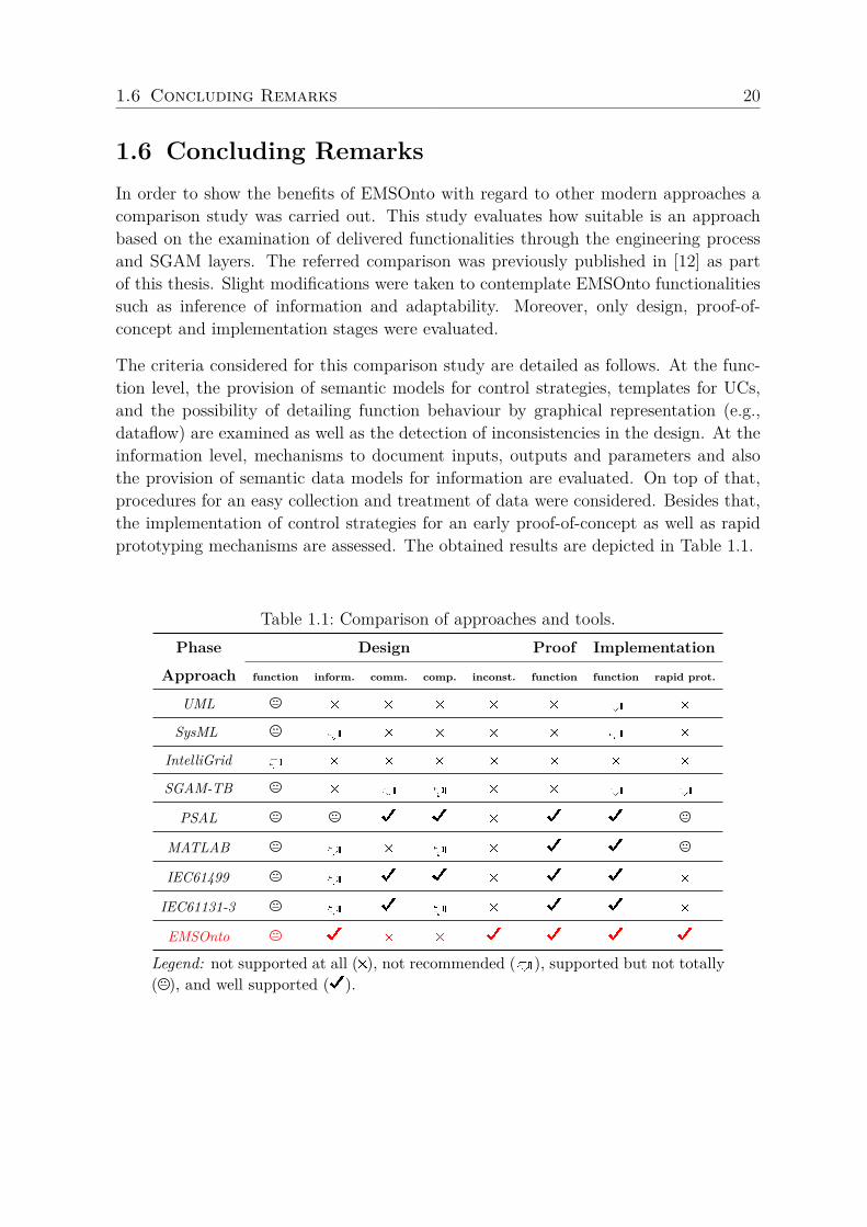
1.6 Concluding RemarksIn order to show the benefits of EMSOnto with regard to other modern approaches acomparison study was carried out. This study evaluates how suitable is an approachbased on the examination of delivered functionalities through the engineering processand SGAM layers. The referred comparison was previously published in [12] as partof this thesis. Slight modifications were taken to contemplate EMSOnto functionalitiessuch as inference of information and adaptability. Moreover, only design, proof-of-concept and implementation stages were evaluated.
The criteria considered for this comparison study are detailed as follows. At the func-tion level, the provision of semantic models for control strategies, templates for UCs,and the possibility of detailing function behaviour by graphical representation (e.g.,dataflow) are examined as well as the detection of inconsistencies in the design. At theinformation level, mechanisms to document inputs, outputs and parameters and alsothe provision of semantic data models for information are evaluated. On top of that,procedures for an easy collection and treatment of data were considered. Besides that,the implementation of control strategies for an early proof-of-concept as well as rapidprototyping mechanisms are assessed. The obtained results are depicted in Table 1.1.
Table 1.1: Comparison of approaches and tools.Phase Design Proof Implementation
Approach function inform. comm. comp. inconst. function function rapid prot.
UML # # # # # d #
SysML d # # # # d #
IntelliGrid d # # # # # # #
SGAM-TB # d d # # d d
PSAL D D # D D
MATLAB d # d # D D
IEC61499 d D D # D D #
IEC61131-3 d D d # D D #
EMSOnto D # # D D D D
Legend: not supported at all (#), not recommended (d), supported but not totally( ), and well supported (D).

1.6 Concluding Remarks 21
This comparison demonstrates that EMSOnto stands out from other modern approachesat almost all the assessed features. In fact, EMSOnto is the only one that identifiesinconsistencies within the planned design. Moreover, it is a good candidate for therapid prototyping of EMS control applications. Furthermore, EMSOnto stands out fromthe others since it also provides a methodology to customize the engineering process.However, it is not suggested for conceptualizing communication and components aspectsof control applications. In contrast, those requirements are covered by PSAL and IEC61499. Moreover, at the function level, there is not a best approach to be suggested.For instance, EMSOnto does not provide a graphical representation of the functionbehaviour. On the contrary, that aspect is well supported by UML. In conclusion, it isrecommended to integrate different approaches to fully support the engineering process.Furthermore, the selection of the appropriate approaches depends on control engineersneeds and practices as well as legacy solutions, among others factors.

Chapter 2
Publications
List of Publications
Publication AC. Zanabria, F. Pröstl Andrén , J. Kathan, and T. I. Strasser.Rapid Prototyping of Multi-Functional Battery Energy Storage System Ap-plications.Applied Sciences, vol. 8, no. 8, 32 pages, 2018.
Publication BC. Zanabria, F. Pröstl Andrén , and T. I. Strasser.An Adaptable Engineering Support Framework for Multi-Functional EnergyStorage System Applications.Sustainability, vol. 10, no. 11, 28 pages, 2018.
Publication CC. Zanabria, A. Tayyebi, F. Pröstl Andrén , J. Kathan, and T. Strasser.Engineering Support for Handling Controller Conflicts in Energy StorageSystems Applications.Energies, vol. 10, no. 10, 24 pages, 2017.

2.1 Publication A 23
2.1 Publication AC. Zanabria, F. Pröstl Andrén , J. Kathan, and T. I. Strasser.Rapid Prototyping of Multi-Functional Battery Energy Storage System Ap-plications.Applied Sciences, vol. 8, no. 8, 32 pages, 2018.
Own contributionThe problem analysis, definition of research goals, and conceptualization of the method-ology were carried out by the applicant. In addition, the applicant implemented aresearch prototype of the proposed solution and carried out all the corresponding val-idation tests. A comparison study of the proposed approach with existing ones is alsodone by the applicant as well as the structuring, writing and editing of the manuscript.The second, third and last author proofread the manuscript and contributed in theproblem analysis. In addition, the second and last author participated in the concep-tualization of the methodology and conducted the supervision of the overall work.
applied sciences
Article
Rapid Prototyping of Multi-Functional Battery EnergyStorage System Applications
Claudia Zanabria 1,* , Filip Pröstl Andrén 1, Johannes Kathan 1 and Thomas I. Strasser 1,2
1 Center for Energy–Electric Energy Systems, AIT Austrian Institute of Technology, 1210 Vienna, Austria;[email protected] (F.P.A.); [email protected] (J.K.); [email protected] (T.I.S.)
2 Institute of Mechanics and Mechatronics, Vienna University of Technology, 1040 Vienna, Austria* Correspondence: [email protected]
Received: 18 July 2018; Accepted: 4 August 2018; Published: 8 August 2018
Abstract: Battery Energy Storage Systems (BESS) are starting to play an important role in today’spower distribution networks. They provide a manifold of services for fulfilling demands andrequests from diverse stakeholders, such as distribution system operators, energy market operators,aggregators but also end-users. Such services are usually provided by corresponding EnergyManagement Systems (EMS). This paper analyzes the complexity of the EMS developmentprocess resulting from an evolving power utility automation. As a result, flexibility, complexity,interoperability, and overlapping issues were identified as main concerns to be faced during thedesign and implementation stages of BESS control applications. Current efforts from smart gridand power utility automation standards partially tackle the issues mentioned above. Nevertheless,an integrated methodology that guides and supports control engineers during the whole developmentchain is still missing. Hence, the conception of EMSOnto is introduced. The main achievements ofthis approach include the alignment of BESS design with broadly accepted smart grid standards(i.e., IEC 61850, smart grid architecture model), a common understanding of EMS control applicationsbased on the conception of an ontology, the identification of conflicts within a multi-function BESSand the semi-automatic generation of software artifacts mainly important for EMS validation.To demonstrate the effectiveness of the approach, a selected use case example is designed andvalidated in a hardware-in-the-loop basis. This proves that EMSOnto eases the work of controlengineers resulting in a flexible, adaptable, and error-free EMS design. In addition to this, limitationsof EMSOnto as well as future work are grasped.
Keywords: battery energy storage systems; rapid prototyping; conflicts identification; power utilityautomation; power distribution grid; semantic web technologies; ontology; description logics;model-driven engineering; smart grid architecture model; IEC 61850
1. Introduction
The reduction of greenhouse gas emissions motivates a high penetration of renewable DistributedEnergy Resources (DERs). However, this may negatively influence the power quality (i.e., frequencyand voltage) and surpass the hosting capacity of the corresponding power distribution grids. BatteryEnergy Storage Systems (BESS) are becoming an important actor in the power utility grid due to theirflexibility and support that they offer. Use Cases (UCs) based on BESS participation are considered indifferent studies [1,2], attempting to contribute to voltage and frequency regulation. Other servicessuch as improvement of the hosting capacity and peak-shaving are also possible [3]. Additionally, BESSsupports Energy Market Operators (EMO) to benefit from the spot market prices [4] and the end-userto minimize their energy costs [5]. The implementation of the mentioned UCs implies an efficient useof the Information and Communication Technology (ICT) infrastructure and the integration betweenvarious stakeholders and DERs.
Appl. Sci. 2018, 8, 1326 ; doi:10.3390/app8081326 www.mdpi.com/journal/applsci
2.1 Publication A 24
Appl. Sci. 2018, 8, 1326 2 of 32
Energy Management Systems (EMS) carry out the integration of BESS UCs. Thus, they require toreach a high degree of flexibility and adaptability. Furthermore, their design becomes quite complexsince different power utility equipment and stakeholders are involved. Additionally, due to the offeringof many services, a coordination and alignment of control strategies is required. Those issues amongothers are faced during the development process of EMS. Motivating the conception of a commonvocabulary to be approved by different control engineers dedicated to EMS implementation.
Existent approaches support control engineers during the engineering process; Systems ModelingLanguage (SysML) and Smart Grid Architecture Model (SGAM) are highly recommended at thespecification stage [6]. Power System Automation Language (PSAL), a Domain Specific Language(DSL) for power systems, automates the design and implementation of smart grid applications [7].Besides this, a power utility automation standard called IEC 61850 models DERs functionalities [8].The implementation of them is driven by automation standards such as IEC 61499 [9] andIEC 61131-3 [10]. On this basis, this paper analyzes current smart grid and automation approachesand points out the lack of an integrated framework and methodology that guides control engineersduring the design and implementation phase of EMS applications. As a solution, this paper proposesEMSOnto, a framework focused on interoperability, flexibility, complexity, and overlapping issuesraised during BESS UCs implementation. Current efforts to handle those issues are evaluated, hencea set of four requirements are identified which provides the basis for the EMSOnto conception.
The core part of the EMSOnto approach is an ontology (i.e., EMS-ontology) that models differentaspects of a multi-functional BESS such as potential conflicts between UCs, variables exchanged acrossthe EMS communication architecture, structure of control strategies, etc. This modeling process isaligned with domain-specific approaches like IEC 61850 and SGAM. PSAL proposes a data modelfor power systems also based on SGAM and IEC 61850, but concepts for the abstraction of BESSservices were not tackled. A main benefit of ontologies is to infer new knowledge from explicitknowledge. This benefit is key in the identification of conflicts, a feature supported by EMSOnto andnot contemplated by any of the previous mentioned approaches. In addition to this, a friendly methodto gather information from control engineers based on spreadsheet templates (i.e., EMS-templates)is exposed. This mechanism enables the population of the EMS-ontology. IntelliGrid enables thegathering of data by UC templates, however they are not suitable for collection of static and dynamicvariables presented in an EMS. On the other hand, Model-Driven Engineering (MDE) is employed tosemi-automatically generate software artifacts to be deployed in power system and automation tools.The rapid prototyping of smart grid applications by means of MDE techniques is not a completely newtopic since it was already tackled by PSAL and other works [11]; however, the benefits of an automaticgeneration of software artifacts for the proof-of-concept of BESS applications is not yet addressed.
This paper is structured as follows: Section 2 presents UCs mainly important to BESS support,their corresponding development process are analyzed resulting in the identification of issues tobe target by EMSOnto. Section 3 addresses those issues by analyzing current efforts carried out tohandle them. From this evaluation, gaps and open issues are identified resulting in the statement offour requirements to design EMSOnto. Section 4 presents the core of EMSOnto, an ontology mainlydesigned to meet specific requirements. Additionally, a friendly method to populate the ontologyis addressed by spreadsheet templates. As a sequel, Section 5 designs and implements a selectedUC following the EMSOnto basis. This enables the identification of gaps and guidelines to improveEMSOnto. Finally, Section 6 summarizes and concludes this work.
2. Multi-Functional Energy Storage System Application Development
This section presents a list of selected UCs that address demands from various stakeholders.A correct operation of those UCs requires the follow up of an engineering process. This involvesspecification, design, implementation, and realization stages. Furthermore, the whole developmentchain of an EMS realization is also exposed. In that context, important issues to facilitate the controlengineer’s work and also to reach a flexible and interoperable EMS are raised.
2.1 Publication A 25
Appl. Sci. 2018, 8, 1326 3 of 32
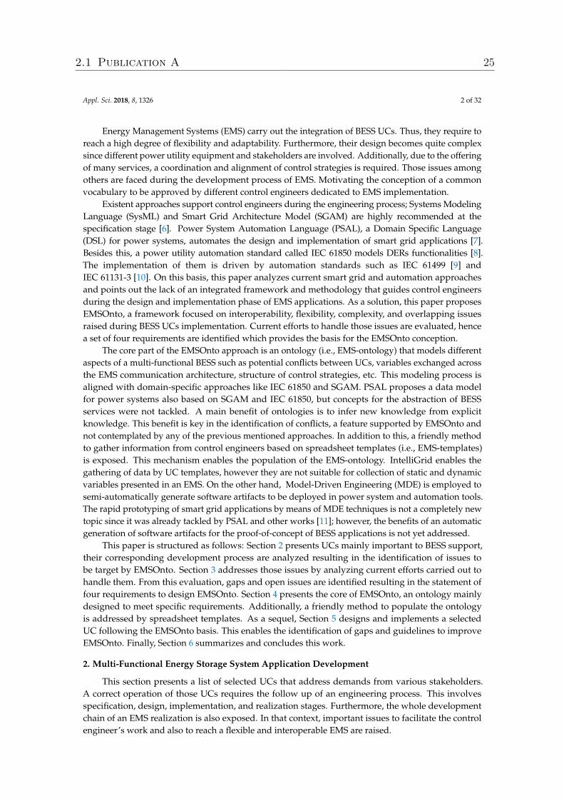
2.1. Use Cases and Applications
The selection of use cases UC1–UC5 is based on common services provided mainly by smallscale energy storage systems (∼ > 3.6 kW & < 4.8 kW), see Table 1. An extended list can be found inthe study [4] where a categorization by objectives, such as reduction of energy costs, power systemstability, and market integration is carried out. A scheme that represents electrical devices connectionand communication links, in the frame of those UC, is depicted in Figure 1. A BESS is integrated withinthe low-voltage grid to mainly support the user to minimize energy costs. This is reached by storingthe Photovoltaic (PV) generated energy not consumed by the local load. This mechanism correspondsto UC3 where the customer is the main benefactor. However, those batteries are able to providesupport to the grid operator for power system stability purposes. Thus, not only self-consumption(UC3) is pursued but other services such as voltage and frequency regulation (UC1-UC2). Followingthat premise, the study [5] is also selected (UC4); it defines a multi-functional system embedded withpeak-shaving and reduction of price services. An ensemble of storage services is also met by UC5 [1].That case study gathers voltage control and two other services, it is an appealing example since eachservice rents one part of the whole capacity of a medium scale BESS. At first glance, it might seem thatservices do not need to be aligned because of the capacity allocation procedure. However, study [1]analyzes conflict issues regarding a full provision of those services. Since conflict identification isa main requirement to be covered by the EMS-ontology, UC5 is included in the selection of UCs.
Small/ Mediumscale ESS
PPV
EnergyManagementSystem
PloadPbat Qbat
Low Voltage Grid
Photovoltaic(PV) Load
Smart meterPCC
Pgrid
network operatorEMO
Communication link
Figure 1. EMS setup with corresponding communication architecture.
Table 1. Use cases derived from the integration of BESS into a low voltage grid
Use Case, Controller Type Description
Volt-VAr mode (UC1) Reactive power from the battery (Qbat) is injected to stabilize the voltage at thePoint of Common Coupling (PCC), see Volt-Var mode VV1 in [12].
Frequency-watt (FW) (UC2) Active power from the battery (Pbat) supports the balancing of frequency ofthe grid (Fgrid), see FW mode FW21 in [12].
Self-consumption (UC3) Pbat helps to minimize the energy consumed from the grid (Pgrid), see PVBat1control strategy in [13].
Min. of costs with peak shaving (UC4) Electricity costs are reduced and peak-shaving is pursued, see [5].
Multi-functional BESS medium scale (UC5) Self-consumption is provided to a group of households by injecting activepower (Pbat), Primary Control Reserve (PCR) participation follows the logicin UC2. Voltage is controlled by reactive power provision Qbat; to accomplishthis, a Proportional Integral (PI) controller is designed as exposed in [1].
2.1 Publication A 26
Appl. Sci. 2018, 8, 1326 4 of 32
2.2. Specification and Development Process
The realization of EMS control applications requires following certain stages, which involvesspecification, design, proof-of-concept, implementation, and deployment [14]. Those steps are addressedin this section.
At the specification stage, the stakeholders, DERs, and Intelligent Electronic Devices (IEDs),involved in the system under study, are identified. In addition to this, the communication and physicalarchitecture are suggested. This results in a list of requirements to be addressed during the designphase. Subsequently, at the design level, solutions to define the specific behavior and structure ofcontrol strategies embedded by an EMS are evaluated. Hence, a list of variables encompassing control,setpoint and measurement signals are properly described. This description also gathers informationrelated to protocols communication. Thus, the communication interfaces that allow interconnectionacross the power distribution application are also specified. Furthermore, the allocation of controlstrategies through the ICT hardware infrastructure is determined as well.
The validation of the proposed control strategies is carried out at the proof-of-concept phase.At that stage, models of IEDs (e.g., smart meters) and DERs (e.g., BESS) are built and deployed intoa power system emulator (e.g., MATLAB/Simulink, DlgSILENT PowerFactory), along with the controllogic of the EMS [15]. The transition from design to proof-of-concept may entail communication andstability issues that were not considered at the design stage. Hence, an iterative refinement of the controlalgorithms are considered. Afterwards, the deployment of the validated control algorithms takes placeat the implementation phase. A programming language compatible with a specific hardware controlleris chosen to deploy the logic, usually this is driven by automation standards such as IEC 61499 [9]and IEC 61131-3 [10]. The validation of implementation phase is carried out by real-time simulations,controller-hardware-in-the-loop, and/or laboratory-based tests [16].
2.3. Open Issues
A closer analysis of the abovementioned design and engineering process results in the followingissues which need to be addressed:
• Flexibility: The integration of new and different actors into the power distribution grid such asElectrical Vehicles (EV) and EMO motivates evolving services focused on BESS participation.Thus, EMS should be flexible enough to implement those services and future ICT requirements.
• Complexity: The complex-nature of EMS is based on the manifold of services provided by BESSand the deployment of them in the ICT and power system infrastructure. The implementation ofsuch services may be centralized or decentralized. In case of a decentralized configuration, whereservices are deployed in different hardware controllers, more than one control engineer may berequired for the EMS design. Thereby, the lack of a common vocabulary and design languagemay lead to errors during EMS design and later on operation in the field.
• Overlapping: An EMS focused on multi-services for BESS is vulnerable to conflicts between UCs.This overlapping across them could cause a non-expected function behavior. For instance, an EMSthat operates UC2 and UC3 would need to setup mechanisms to align both use cases in the eventof a simultaneous operation. Otherwise, those UCs would not be attained.
• Interoperability: The realization and validation of smart grid and BESS-based applications entailsthe use of a wide range of power system, automation and communication tools. This goes frompower system emulators/design, network simulators to co-simulation frameworks. However,a method to interoperate those tools during the whole chain of the engineering process is missing.
3. Related Work and Background
Issues which need to be tackled during the engineering process were previously highlighted. In thissection, the state-of-the-art and related work are analyzed and discussed. Necessary requirements forimproving the status-quo are identified, which provide cornerstones for the rapid development of UCsand applications.
2.1 Publication A 27
Appl. Sci. 2018, 8, 1326 5 of 32
3.1. Smart Grid Domain Standards
The main concern of the current study is to employ information models from recommendedinternational standards to derive an interoperable and flexible solution. Data models for the powersystem domain are outlined in the IEC Smart Grid Standardization Roadmap [17]. On this basis,a collection of standards mainly important to DER involved in BESS UCs has been gathered, resultingin the following list:
• IEC 61970/IEC 61968 Common Information Model (CIM): Its main concern is to ensure interoperabilityacross power networks, [18]. Thereby, it offers a common semantic for EMS, Supervisory andControl Data Acquisition (SCADA) and power system topology. This is formally represented bya Unified Modeling Language (UML) model, including over 1300 classes.
• IEC 61850: It is mainly conceived to improve interoperability between IEDs in a power systemsubstation; nowadays, it has been extended to DERs and power utility components among otherareas [8]. Functional aspects of an IED are mapped into a Logical Node (LN). They are referencedin the standard IEC 61850-7-4 and extended by IEC 61850-7-420 [19], where functionalities of DERssuch as inverters and batteries are modeled.
• IEC 62325: It provides a set of standards related to market communication using CIM, coveringdata models for market participants and market operators.
• IEC 62056: It applies mainly to smart home and data exchange for meter reading.• Open Platform Communications Unified Architecture (OPC UA): Since the EMS should support
the exchange with other IEDs distributed along the power utility grid, the consideration ofinformation models from the automation domain such as OPC UA is relevant. It is a standardof OPC foundation that focuses on exchanging real-time data within the process automation.It is platform-independent, thereby not tied to one operating system. It is standardized underIEC 62541, part 5 of that standard defines the information model (IEC 62541-5) [20].
3.2. Smart Grid Control Application Development Approaches
The development of smart grid control applications has been supported by a collection ofapproaches. Those are characterized by domain standards (SGAM, CIM, UML, etc.), well recognizedtools (MATLAB/Simulink, etc.) and frameworks (PSAL, etc.). A comparison that measures theapplicability of them through the design, proof-of-concept and implementation phase is carried out inthis section. A brief introduction to the approaches is firstly described below:
• Unified Modeling Language: UML is a general-purpose language for an object-oriented softwaredevelopment [21]. It has been standardized by the Object Management Group (OMG) and approvedas an ISO standard. UML specifies behavior and structural diagrams to model software applications.Thereby, it has been used in the power system domain to model use cases [22].
• System Modeling Language (SysML): SysML is conceived as an extension of a subset of UML. It ismainly designed to support the system engineering process (i.e., specification, design). Thereby,elements in UML not required by systems engineering were excluded to conceive SysML [21].
• IntelliGrid (IEC 62559): Intelligrid introduces a methodology to document and detail smart grid UCs.From this, a UC template [23] that covers best practices to describe requirements engineering isoriginated. In those templates, a UC may be described by a visual representation (e.g., UML diagram).IEC 62559 is largely accepted by the power system community as an example the adoption of it bythe ELECTRA project [22].
• Smart Grid Architecture Model: SGAM is introduced by the SG-CG/RA (Smart Grid CoordinationGroup/Reference Architecture) [24]. SGAM is conceived to model smart grid uses cases architecturein a technology-neutral manner. It consists of five interoperability layers, those layers are matchedto a smart grid plane composed of domains and zones. The domains cover the electricity conversionchain (i.e., transmission, distribution, etc.). The zones cover the automation pyramid (i.e., process,field, etc.). An implementation of SGAM is conceived in [25] as a plugin of the Sparx SystemsEnterprise Architecture tool, it is called SGAM-Toolbox (SGAM-TB).
2.1 Publication A 28
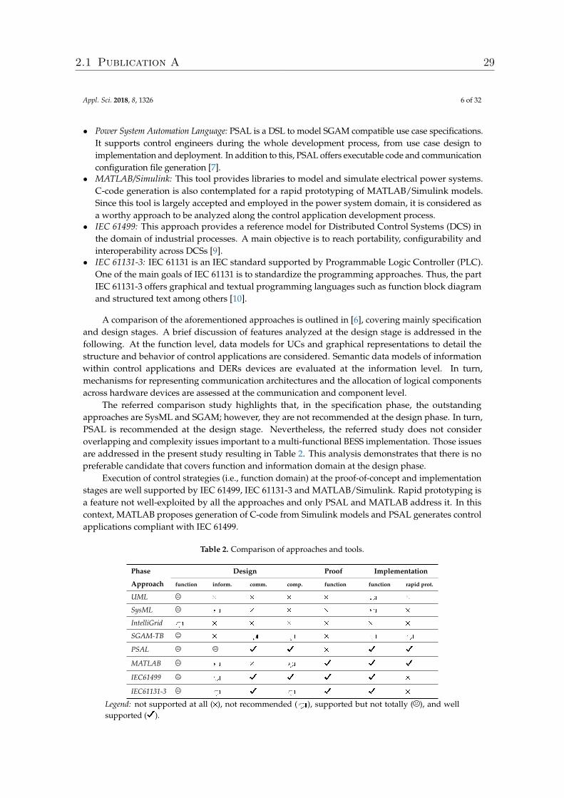
Appl. Sci. 2018, 8, 1326 6 of 32
• Power System Automation Language: PSAL is a DSL to model SGAM compatible use case specifications.It supports control engineers during the whole development process, from use case design toimplementation and deployment. In addition to this, PSAL offers executable code and communicationconfiguration file generation [7].
• MATLAB/Simulink: This tool provides libraries to model and simulate electrical power systems.C-code generation is also contemplated for a rapid prototyping of MATLAB/Simulink models.Since this tool is largely accepted and employed in the power system domain, it is considered asa worthy approach to be analyzed along the control application development process.
• IEC 61499: This approach provides a reference model for Distributed Control Systems (DCS) inthe domain of industrial processes. A main objective is to reach portability, configurability andinteroperability across DCSs [9].
• IEC 61131-3: IEC 61131 is an IEC standard supported by Programmable Logic Controller (PLC).One of the main goals of IEC 61131 is to standardize the programming approaches. Thus, the partIEC 61131-3 offers graphical and textual programming languages such as function block diagramand structured text among others [10].
A comparison of the aforementioned approaches is outlined in [6], covering mainly specificationand design stages. A brief discussion of features analyzed at the design stage is addressed in thefollowing. At the function level, data models for UCs and graphical representations to detail thestructure and behavior of control applications are considered. Semantic data models of informationwithin control applications and DERs devices are evaluated at the information level. In turn,mechanisms for representing communication architectures and the allocation of logical componentsacross hardware devices are assessed at the communication and component level.
The referred comparison study highlights that, in the specification phase, the outstandingapproaches are SysML and SGAM; however, they are not recommended at the design phase. In turn,PSAL is recommended at the design stage. Nevertheless, the referred study does not consideroverlapping and complexity issues important to a multi-functional BESS implementation. Those issuesare addressed in the present study resulting in Table 2. This analysis demonstrates that there is nopreferable candidate that covers function and information domain at the design phase.
Execution of control strategies (i.e., function domain) at the proof-of-concept and implementationstages are well supported by IEC 61499, IEC 61131-3 and MATLAB/Simulink. Rapid prototyping isa feature not well-exploited by all the approaches and only PSAL and MATLAB address it. In thiscontext, MATLAB proposes generation of C-code from Simulink models and PSAL generates controlapplications compliant with IEC 61499.
Table 2. Comparison of approaches and tools.
Phase Design Proof Implementation
Approach function inform. comm. comp. function function rapid prot.
UML # # # # d #
SysML d # # # d #
IntelliGrid d # # # # # #
SGAM-TB # d d # d d
PSAL D D # D D
MATLAB d # d D D D
IEC61499 d D D D D #
IEC61131-3 d D d D D #
Legend: not supported at all (#), not recommended (d), supported but not totally ( ), and wellsupported (D).
2.1 Publication A 29
Appl. Sci. 2018, 8, 1326 7 of 32
3.3. Ontologies for Smart Grid Applications
Ontologies search for a formal representation and categorization of information abstracted fromreal systems. This is achieved by referencing the components: classes, individuals, relations, attributes,rules, etc. [26]. The main advantage of ontologies is the inference of new knowledge from explicitknowledge by the execution of reasoning mechanisms. The most well known ontology language isOntology Web Language (OWL), a key benefit offered is the expression of complex knowledge ina machine-readable form. Moreover, due to OWL being based on description logics (DL), an expressiveformal knowledge representation is obtained.
DL give mechanisms to describe accurately ontologies by introducing the terminological (TBox)and assertional (ABox) component [27]. The TBox contains sentences describing concepts andrelation between concepts. Instantiation of those concepts are carried out by the ABox. For instance,the statement: an EMS embeds more than one service, belongs to the TBox, and the concepts identifiedare EMS and service. In turn, the sentence: frequency-watt mode is a service belongs to the ABox, wherethe individual frequency-watt is an instance of the concept service.
A mechanism to enhance the reasoning process embedded within ontologies is by stating rules,which are statements in the form of “if X then Y” sentence. The W3C consortium recommends SemanticWeb Rules Languages (SWRL) to denote them.
The tasks typically solved with ontologies corresponds mainly to three categories. The firstone is the ontology alignment, the study [28] proposes an ontology matching process to align datamodels of two broadly accepted smart grid standards the CIM and IEC 61850. Additionally, in thestudy [29] an ontology-driven approach transforms control systems into IEC 61499 control applicationsby using eSWRL an extension of the SWRL. Another goal of the various ontology applications isthe integration of knowledge (second category). An ontology for smart grid interactions in BuildingEnergy Management Systems (BEMS) to optimize end-user consumption is built in [30]. In that light,models for communication technologies, interaction between stakeholders and grid structure wereaddressed. Another example is an smart grid information model that combines weather, spatial andtime ontology applied to dynamic demand response applications [31]. The third category is related toidentification of critical errors and faults at the design phase of the engineering process [32,33]. It isworth noting that none of the exposed approaches is multi-functional BESS oriented.
3.4. Model-Driven Engineering in Power Systems
The main focus of MDE is to improve the engineering process by enhancing the compatibilitybetween systems. Thus, MDE defines a common understanding of the system under study by theestablishment of models. In that basis, meta-modeling, model transformation and code generationmechanisms are carried out [34]. MDE has been largely applied to manufacture systems [35] but notsubstantially to the power utility domain. In this light, studies that support the automation of thesmart grid control application process by means of MDE are given in [7,11,36].
3.5. Research Needs and Requirements
A previous study evaluates the efforts done to tackle the issues exposed in Section 2.3, resultingin the following four main requirements for this work:
• Alignment with Domain Standards (R1): An appropriate solution to model a multi-functional BESSshould benefit from the extensive data models provided by the mentioned standards in Section 3.1.
• Common Ontology for Multi-Functional BESS (R2): A comparison of smart grid control developmentapproaches was carried out in Section 3.2. This demonstrates a lack of one approach that fullycovers the function and information domains during the design phase. What is not covered isa method to handle a high amount of data and also a vocabulary for a common understandingof EMS applications. The characterization of EMS behavior is dismissed since it is completelycovered by other approaches (e.g., MATLAB, IEC 61499). Attempts to propose a pattern for control
2.1 Publication A 30
Appl. Sci. 2018, 8, 1326 8 of 32
strategies were done in SGAM. However, it needs to be enlarged in order to cover features mainlyimportant to BESS use cases. An ontology is a good candidate to integrate the knowledge fromEMS as highlighted in Section 3.3. Thereby, R2 searches for an ontology focused on multi-functionalBESS and also for mechanisms to achieve a population of it. The resulting ontology that representsand describes EMS should guide control engineers during the design stage. A derived benefitfrom this is to enable the access of EMS capabilities to external systems (e.g., EMO).
• Identification of Conflicts and Inconsistencies (R3): An early diagnosis of potential conflicts withinEMS corresponds to the overlapping issue in Section 2.3. That topic was tackled in [37], as a resulta classification of conflicts (Conflict CI − CVI) and its modeling by ontologies is achieved.In addition to this, the study formally defines DL queries to identify the classified conflictsand a handling solution per conflict type is exposed and recommended. The outcomes from [37]should be implemented in a whole solution that supports the design of EMS.
• Generation of Software Artifacts (R4): One of the issues highlighted in Section 2.3 requires implementingEMS applications into different power system tools (i.e., design, emulator). Thereby, the generation ofsoftware artifacts at the proof-of-concept and implementation phase should be assured. MDE invokestwo types of transformations: Model-to-model (M2M) and Model-to-text (M2T) transformationsby the setting up of transformation rules. Both transformations should be carried out at thedesign stage, and this would improve the rapidity and interoperability of the EMS engineeringprocess. The generation of code and models from an EMS platform-independent model is part of therequirement R4.
In summary, current efforts to face the issues encountered during the EMS development processwere evaluated. Thereby, current standards for the power utility automation domain are studied(e.g., IEC 61850). As a result, R1 motivates the use of existent information models. Moreover,approaches that support the whole chain of the development process (e.g., SGAM, PSAL) are comparedto realize the specific points that need to be targeted to address the complexity issue. This resultsin R2, and it searches for a common vocabulary for BESS UCs. Afterwards, the overlapping withina multi-functional BESS motivates the assessment of ontologies in smart grids. That topic was alreadyaddressed in [38]. Hence, R3 envisages the implementation of the outcomes from the mentioned studyin EMSOnto. The interoperability issue is tackled by model-driven engineering techniques, and thisis conceptualized in R4. As a result, the basis for the conception of EMSOnto are formulated underrequirements R1-R4.
4. Application Development with the EMSOnto Approach
In the last section, the need for an engineering support for designing multi-functional BESScontrol applications has been identified and discussed. This design is driven by the fulfillment ofcertain requirements (i.e., R1–R4). In this context, model-driven engineering together with ontologiesare combined to offer a flexible solution—the so-called EMSOnto approach. This section introducesthe main ideas and concepts behind it, especially the EMS-ontology which forms the main part ofthis approach. Thus, the design of the EMS-ontology is presented and discussed accordingly torequirements R1–R4. Additionally, a user-friendly method to populate the ontology is also addressed.
4.1. General Overview of the Approach
The whole picture of the EMSOnto framework and the support it provides to control engineersduring EMS-development are shown in Figure 2. Across the different phases in the design anddevelopment process, requirements R1–R4 are properly addressed.
2.1 Publication A 31
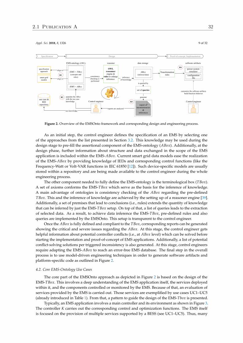
Appl. Sci. 2018, 8, 1326 9 of 32
report of inconsistencies
& inferences
inference of knowledge
EMSontology (OWL)
consistency checking is performed
align to
(concepts androles)
EMS − TBox
data storage
power systemsimulator
software artifacts
configurationfile
reasoner
R4specificationapproach
Specification Design Proofofconcept, Implementation
smart gridmodels
align to
EMS − ABox
OWLreasonner engine &
rules to enlarge inference
generate
set of queries
R3
Transformationrules
populate the with the use case knowledge
ABox
reports are analyzed
(inferred data)ABox
is queried by
Control engineerControl engineer
customize the software artifacts build function behavior
R1
R2use case &
IEDrepository
use knowledge
Figure 2. Overview of the EMSOnto framework and corresponding design and engineering process.
As an initial step, the control engineer defines the specification of an EMS by selecting oneof the approaches from the list presented in Section 3.2. This knowledge may be used during thedesign stage to pre-fill the assertional component of the EMS-ontology (ABox). Additionally, at thedesign phase, further information about structure and data exchanged in the scope of the EMSapplication is included within the EMS-ABox. Current smart grid data models ease the realizationof the EMS-ABox by providing knowledge of IEDs and corresponding control functions (like theFrequency-Watt or Volt-VAR functions in IEC 61850 [12]). Such device-specific models are usuallystored within a repository and are being made available to the control engineer during the wholeengineering process.
The other component needed to fully define the EMS-ontology is the terminological box (TBox).A set of axioms conforms the EMS-TBox which serve as the basis for the inference of knowledge.A main advantage of ontologies is consistency checking of the ABox regarding the pre-definedTBox. This and the inference of knowledge are achieved by the setting up of a reasoner engine [39].Additionally, a set of premises that lead to conclusions (i.e., rules) extends the quantity of knowledgethat can be inferred by just the EMS-TBox setup. On top of that, a list of queries leads to the extractionof selected data. As a result, to achieve data inference the EMS-TBox, pre-defined rules and alsoqueries are implemented by the EMSOnto. This setup is transparent to the control engineer.
Once the ABox is fully defined and compliant to the TBox, corresponding reports can be generatedshowing the critical and severe issues regarding the ABox. At this stage, the control engineer getshelpful information about potential controller conflicts (i.e., at ABox level) which can be solved beforestarting the implementation and proof-of-concept of EMS applications. Additionally, a list of potentialconflict-solving solutions per triggered inconsistency is also generated. At this stage, control engineersrequire adapting the EMS-ABox to reach an error-free EMS database. The final step in the overallprocess is to use model-driven engineering techniques in order to generate software artifacts andplatform-specific code as outlined in Figure 2.
4.2. Core EMS-Ontology Use Cases
The core part of the EMSOnto approach as depicted in Figure 2 is based on the design of theEMS-TBox. This involves a deep understanding of the EMS application itself, the services deployedwithin it, and the components controlled or monitored by the EMS. Because of that, an evaluation ofservices provided by the EMS is carried out. Those services are exemplified by use cases UC1–UC5(already introduced in Table 1). From that, a pattern to guide the design of the EMS-Tbox is presented.
Typically, an EMS application involves a main controller and its environment as shown in Figure 3.The controller K carries out the corresponding control and optimization functions. The EMS itselfis focused on the provision of multiple services supported by a BESS (see UC1–UC5). Thus, many
2.1 Publication A 32
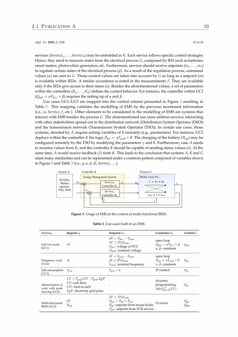
Appl. Sci. 2018, 8, 1326 10 of 32
services (Service1, . . . , Servicen) may be embedded in K. Each service follows specific control strategies.Hence, they need to measure states from the electrical process G, composed by IED such as batteries,smart meters, photovoltaic generators, etc. Furthermore, services should receive setpoints (w1, . . . , wn)to regulate certain states of the electrical process (y). As a result of the regulation process, commandvalues (u) are sent to G. Those control values are taken into account by G as long as a setpoint (m)is available within IEDs. A similar occurrence is noted in the measurements f . They are availableonly if the IEDs give access to their states (s). Besides the aforementioned values, a set of parameterswithin the controllers (K1, . . . , Kn) defines the control behavior. For instance, the controller within UC1(Qbat = αVpcc + β) requires the setting up of α and β.
Use cases UC1–UC5 are mapped into the control scheme presented in Figure 3 resulting inTable 3. This mapping validates the modelling of EMS by the previous mentioned information(i.e., w, Service, f , etc.). Other elements to be considered in the modelling of EMS are systems thatinteract with EMS besides the process G. The aforementioned use cases address services interactingwith other stakeholders spread out in the distribution network (Distribution System Operator (DSO))and the transmission network (Transmission System Operator (TSO)). In certain use cases, thosesystems, denoted by A, require setting variables of K remotely (e.g., parameters). For instance, UC2deploys within the controller K the logic Pbat = γFgrid + θ. The charging of the battery (Pbat) may beconfigured remotely by the TSO by modifying the parameters γ and θ. Furthermore, case A needsto monitor values from K, and the controller K should be capable of sending status values (s). At thesame time, A would receive feedback ( f ) from K. This leads to the conclusion that systems A, K and Gshare many similarities and can be represented under a common pattern composed of variables shownin Figure 3 and Table 3 (i.e., y, u, w, K, Service, . . . ).
Controller Service1
K1
BESS, Grid, PV,...
w1
Energy Management System
u
Process G
y
f
Controller K
= Ax + bux′
s
System A
SCADA,Marketoperator,TSO, DSO
≤ x ≤xmin xmaxController Servicen
Kn
wn
m
Figure 3. Usage of EMS in the context of multi-functional BESS.
Table 3. Use cases built-in an EMS.
Servicen Regulat.-y Setpoint-wn Controller-Kn Control-u
Volt-VAr mode(UC1)
δV
δV = Vpcc −VnomδV ≤ 3%VnomVpcc: voltage at PCCVnom: nominal voltage
open loopQbat = αVpcc + βα, β: constants
Qbat
Frequency-watt(UC2)
δFδF = Fgrid − FnomδF ≤ 2%FnomFnom: nominal frequency
open loopPbat = γFgrid + θ
γ, θ: constantsPbat
Self-consumption(UC3)
Pgrid Pgrid = 0 PI control Pbat
Minimization ofcosts with peakshaving (UC4)
CF = Pgrid.FiT −Pgrid.EgPCF: cash flowFiT: feed-in tarifEgP: electricity grid price
-dynamicprogramming,Min ∑T
t=0(CF)Pbat
Multi-functionalBESS (UC5)
δVPbat
δV ≤ 3%VnomPbat = Phh + PpcrPhh: setpoint from house-holdsPpcr: setpoint from PCR service
PI controlPbatQbat
2.1 Publication A 33
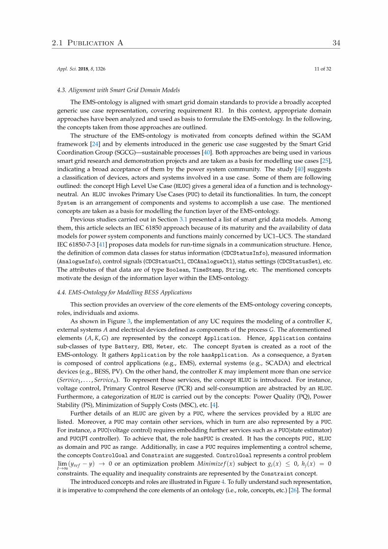
Appl. Sci. 2018, 8, 1326 11 of 32
4.3. Alignment with Smart Grid Domain Models
The EMS-ontology is aligned with smart grid domain standards to provide a broadly acceptedgeneric use case representation, covering requirement R1. In this context, appropriate domainapproaches have been analyzed and used as basis to formulate the EMS-ontology. In the following,the concepts taken from those approaches are outlined.
The structure of the EMS-ontology is motivated from concepts defined within the SGAMframework [24] and by elements introduced in the generic use case suggested by the Smart GridCoordination Group (SGCG)—sustainable processes [40]. Both approaches are being used in varioussmart grid research and demonstration projects and are taken as a basis for modelling use cases [25],indicating a broad acceptance of them by the power system community. The study [40] suggestsa classification of devices, actors and systems involved in a use case. Some of them are followingoutlined: the concept High Level Use Case (HLUC) gives a general idea of a function and is technology-neutral. An HLUC invokes Primary Use Cases (PUC) to detail its functionalities. In turn, the conceptSystem is an arrangement of components and systems to accomplish a use case. The mentionedconcepts are taken as a basis for modelling the function layer of the EMS-ontology.
Previous studies carried out in Section 3.1 presented a list of smart grid data models. Amongthem, this article selects an IEC 61850 approach because of its maturity and the availability of datamodels for power system components and functions mainly concerned by UC1–UC5. The standardIEC 61850-7-3 [41] proposes data models for run-time signals in a communication structure. Hence,the definition of common data classes for status information (CDCStatusInfo), measured information(AnalogueInfo), control signals (CDCStatusCtl, CDCAnalogueCtl), status settings (CDCStatusSet), etc.The attributes of that data are of type Boolean, TimeStamp, String, etc. The mentioned conceptsmotivate the design of the information layer within the EMS-ontology.
4.4. EMS-Ontology for Modelling BESS Applications
This section provides an overview of the core elements of the EMS-ontology covering concepts,roles, individuals and axioms.
As shown in Figure 3, the implementation of any UC requires the modeling of a controller K,external systems A and electrical devices defined as components of the process G. The aforementionedelements (A, K, G) are represented by the concept Application. Hence, Application containssub-classes of type Battery, EMS, Meter, etc. The concept System is created as a root of theEMS-ontology. It gathers Application by the role hasApplication. As a consequence, a Systemis composed of control applications (e.g., EMS), external systems (e.g., SCADA) and electricaldevices (e.g., BESS, PV). On the other hand, the controller K may implement more than one service(Service1, . . . , Servicen). To represent those services, the concept HLUC is introduced. For instance,voltage control, Primary Control Reserve (PCR) and self-consumption are abstracted by an HLUC.Furthermore, a categorization of HLUC is carried out by the concepts: Power Quality (PQ), PowerStability (PS), Minimization of Supply Costs (MSC), etc. [4].
Further details of an HLUC are given by a PUC, where the services provided by a HLUC arelisted. Moreover, a PUC may contain other services, which in turn are also represented by a PUC.For instance, a PUC(voltage control) requires embedding further services such as a PUC(state estimator)and PUC(PI controller). To achieve that, the role hasPUC is created. It has the concepts PUC, HLUCas domain and PUC as range. Additionally, in case a PUC requires implementing a control scheme,the concepts ControlGoal and Constraint are suggested. ControlGoal represents a control problemlimt→∞
(yre f − y) → 0 or an optimization problem Minimize f (x) subject to gi(x) ≤ 0, hj(x) = 0
constraints. The equality and inequality constraints are represented by the Constraint concept.The introduced concepts and roles are illustrated in Figure 4. To fully understand such representation,
it is imperative to comprehend the core elements of an ontology (i.e., role, concepts, etc.) [26]. The formal
2.1 Publication A 34
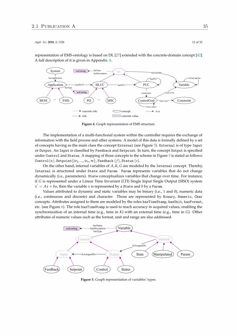
Appl. Sci. 2018, 8, 1326 12 of 32
representation of EMS-ontology is based on DL [27] extended with the concrete-domain concept [42].A full description of it is given in Appendix A.
hasHLUChasType
Application HLUC
BESS EMS
hasApplication
System
hasPUC
hasPUC
manipulate
PUC
hasTypehasDescription
UC hasVariable
Variable
concrete valueconcept
roleconcrete role
PQ MSC
is a
hasFctVar
ControlGoal ConstrainthasConst
IsVarLinkVar
xsd:string
xsd:string
... ...
IsFcLinkFc
Figure 4. Graph representation of EMS structure.
The implementation of a multi-functional system within the controller requires the exchange ofinformation with the field process and other systems. A model of this data is formally defined by a setof concepts having as the main class the concept External (see Figure 5). External is of type Inputor Output. An Input is classified by Feedback and Setpoint. In turn, the concept Output is specifiedunder Control and Status. A mapping of those concepts to the scheme in Figure 3 is stated as follows:Control(u), Setpoint{w1, ..., wn, m}, Feedback ( f ), Status (s).
On the other hand, internal variables of A, K, G are modeled by the Internal concept. Thereby,Internal is structured under State and Param. Param represents variables that do not changedynamically (i.e., parameters). State conceptualizes variables that change over time. For instance,if G is represented under a Linear Time Invariant (LTI) Single Input Single Output (SISO) systemx′= Ax + bu, then the variable x is represented by a State and b by a Param.
Values attributed to dynamic and static variables may be binary (i.e., 1 and 0), numeric data(i.e., continuous and discrete) and character. Those are represented by Binary, Numeric, Charconcepts. Attributes assigned to them are modeled by the roles hasTimeStamp, hasUnit, hasFormat,etc. (see Figure 6). The role hasTimeStamp is used to reach accuracy in acquired values, enabling thesynchronization of an internal time (e.g., time in K) with an external time (e.g., time in G). Otherattributes of numeric values such as the format, unit and range are also addressed.
hasNamehasDescription
hasTypeVariable
ExternalIsAssignedTo
Internal
Input IsAssignedTo Output Param
Feedback Setpoint Control Status
State
xsd:string
Manipulated
Figure 5. Graph representation of variables’ types.
2.1 Publication A 35
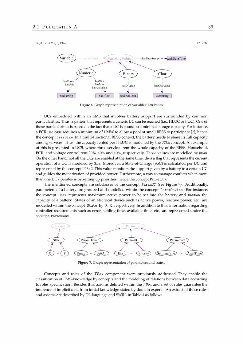
Appl. Sci. 2018, 8, 1326 13 of 32
Variable VariableValue hasTimeStamp
hasFormat hasUnit
hasMax hasMin
hasAnaValue
Numeric
hasDiValue
Binary
hasVarValue xsd:DateTime
xsd:string
hasCharValue
Char
xsd:float xsd:boolean xsd:string
Figure 6. Graph representation of variables’ attributes.
UCs embedded within an EMS that involves battery support are surrounded by commonparticularities. Thus, a pattern that represents a generic UC can be reached (i.e., HLUC or PUC). One ofthose particularities is based on the fact that a UC is bound to a minimal storage capacity. For instance,a PCR use case requires a minimum of 1 MW to allow a pool of small BESS to participate [2], hencethe concept BessSize. In a multi-functional BESS context, the battery needs to share its full capacityamong services. Thus, the capacity rented per HLUC is modelled by the UCAh concept. An exampleof this is presented in UC5, where three services rent the whole capacity of the BESS. Household,PCR, and voltage control rent 20%, 40% and 40%, respectively. Those values are modelled by UCAh.On the other hand, not all the UCs are enabled at the same time, thus a flag that represents the currentoperation of a UC is modeled by Ena. Moreover, a State-of-Charge (SoC) is calculated per UC andrepresented by the concept UCSoC. This value monitors the support given by a battery to a certain UCand guides the monetization of provided power. Furthermore, a way to manage conflicts when morethan one UC operates is by setting up priorities, hence the concept Priority.
The mentioned concepts are subclasses of the concept ParamUC (see Figure 7). Additionally,parameters of a battery are grouped and modelled within the concept ParamDevice. For instance,the concept Pmax represents maximum active power to be set into the battery and BattAh thecapacity of a battery. States of an electrical device such as active power, reactive power, etc. aremodelled within the concept State by P, Q, respectively. In addition to this, information regardingcontroller requirements such as error, settling time, available time, etc. are represented under theconcept ParamCont.
ParamDeviceState
Param
Pmax BattAh P Q
ParamUC
Ena Priority ...
Internal
... ...
ParamCont
AvailTime SettlingTime ...
Figure 7. Graph representation of parameters and states.
Concepts and roles of the TBox component were previously addressed. They enable theclassification of EMS-knowledge by concepts and the modeling of relations between data accordingto roles specification. Besides this, axioms defined within the TBox and a set of rules guarantee theinference of implicit data from initial knowledge stated by domain experts. An extract of those rulesand axioms are described by DL language and SWRL in Table 4 as follows.
2.1 Publication A 36
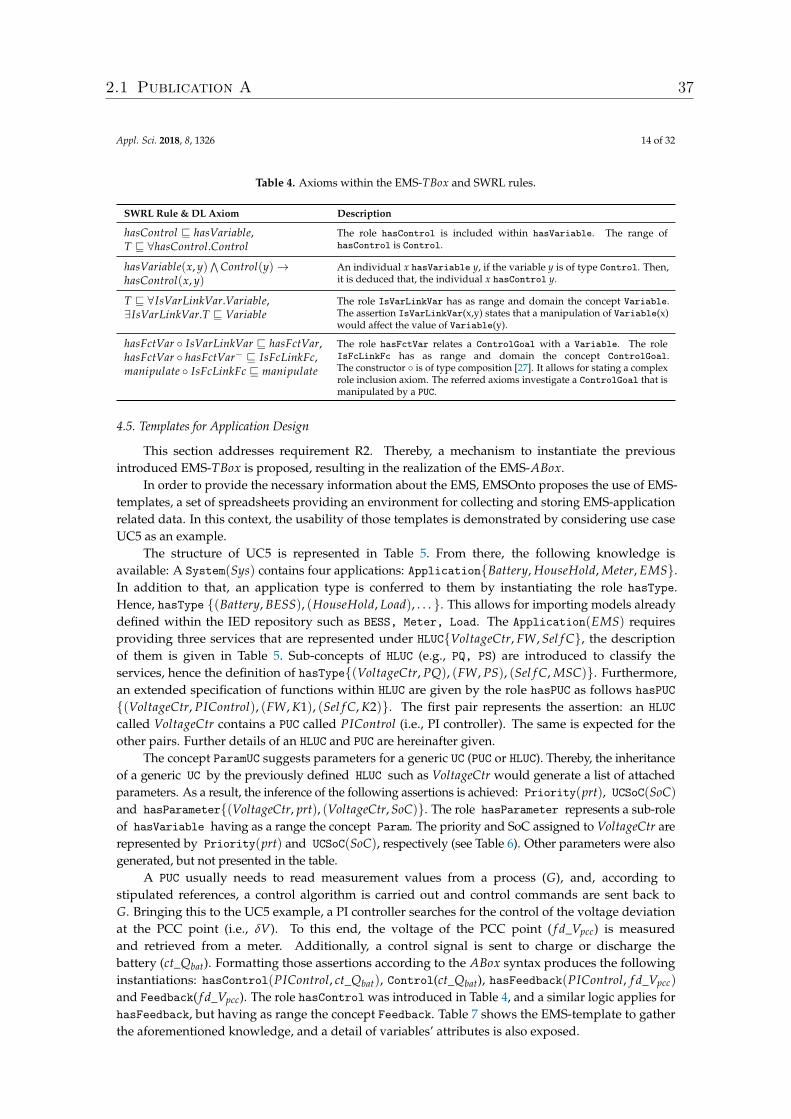
Appl. Sci. 2018, 8, 1326 14 of 32
Table 4. Axioms within the EMS-TBox and SWRL rules.
SWRL Rule & DL Axiom Description
hasControl v hasVariable,T v ∀hasControl.Control
The role hasControl is included within hasVariable. The range ofhasControl is Control.
hasVariable(x, y)∧
Control(y)→hasControl(x, y)
An individual x hasVariable y, if the variable y is of type Control. Then,it is deduced that, the individual x hasControl y.
T v ∀IsVarLinkVar.Variable,∃IsVarLinkVar.T v Variable
The role IsVarLinkVar has as range and domain the concept Variable.The assertion IsVarLinkVar(x,y) states that a manipulation of Variable(x)would affect the value of Variable(y).
hasFctVar ◦ IsVarLinkVar v hasFctVar,hasFctVar ◦ hasFctVar− v IsFcLinkFc,manipulate ◦ IsFcLinkFc v manipulate
The role hasFctVar relates a ControlGoal with a Variable. The roleIsFcLinkFc has as range and domain the concept ControlGoal.The constructor ◦ is of type composition [27]. It allows for stating a complexrole inclusion axiom. The referred axioms investigate a ControlGoal that ismanipulated by a PUC.
4.5. Templates for Application Design
This section addresses requirement R2. Thereby, a mechanism to instantiate the previousintroduced EMS-TBox is proposed, resulting in the realization of the EMS-ABox.
In order to provide the necessary information about the EMS, EMSOnto proposes the use of EMS-templates, a set of spreadsheets providing an environment for collecting and storing EMS-applicationrelated data. In this context, the usability of those templates is demonstrated by considering use caseUC5 as an example.
The structure of UC5 is represented in Table 5. From there, the following knowledge isavailable: A System(Sys) contains four applications: Application{Battery, HouseHold, Meter, EMS}.In addition to that, an application type is conferred to them by instantiating the role hasType.Hence, hasType {(Battery, BESS), (HouseHold, Load), . . . }. This allows for importing models alreadydefined within the IED repository such as BESS, Meter, Load. The Application(EMS) requiresproviding three services that are represented under HLUC{VoltageCtr, FW, Sel f C}, the descriptionof them is given in Table 5. Sub-concepts of HLUC (e.g., PQ, PS) are introduced to classify theservices, hence the definition of hasType{(VoltageCtr, PQ), (FW, PS), (Sel f C, MSC)}. Furthermore,an extended specification of functions within HLUC are given by the role hasPUC as follows hasPUC{(VoltageCtr, PIControl), (FW, K1), (Sel f C, K2)}. The first pair represents the assertion: an HLUCcalled VoltageCtr contains a PUC called PIControl (i.e., PI controller). The same is expected for theother pairs. Further details of an HLUC and PUC are hereinafter given.
The concept ParamUC suggests parameters for a generic UC (PUC or HLUC). Thereby, the inheritanceof a generic UC by the previously defined HLUC such as VoltageCtr would generate a list of attachedparameters. As a result, the inference of the following assertions is achieved: Priority(prt), UCSoC(SoC)and hasParameter{(VoltageCtr, prt), (VoltageCtr, SoC)}. The role hasParameter represents a sub-roleof hasVariable having as a range the concept Param. The priority and SoC assigned to VoltageCtr arerepresented by Priority(prt) and UCSoC(SoC), respectively (see Table 6). Other parameters were alsogenerated, but not presented in the table.
A PUC usually needs to read measurement values from a process (G), and, according tostipulated references, a control algorithm is carried out and control commands are sent back toG. Bringing this to the UC5 example, a PI controller searches for the control of the voltage deviationat the PCC point (i.e., δV). To this end, the voltage of the PCC point ( f d_Vpcc) is measuredand retrieved from a meter. Additionally, a control signal is sent to charge or discharge thebattery (ct_Qbat). Formatting those assertions according to the ABox syntax produces the followinginstantiations: hasControl(PIControl, ct_Qbat), Control(ct_Qbat), hasFeedback(PIControl, f d_Vpcc)
and Feedback( f d_Vpcc). The role hasControl was introduced in Table 4, and a similar logic applies forhasFeedback, but having as range the concept Feedback. Table 7 shows the EMS-template to gatherthe aforementioned knowledge, and a detail of variables’ attributes is also exposed.
2.1 Publication A 37
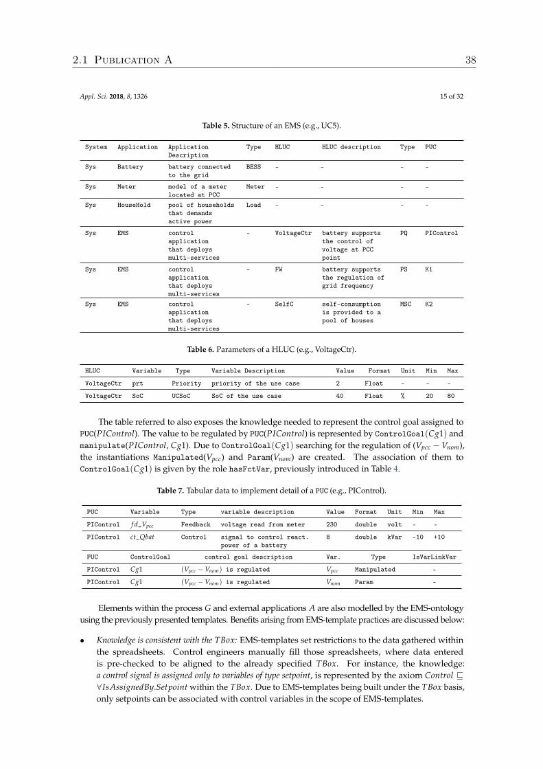
Appl. Sci. 2018, 8, 1326 15 of 32
Table 5. Structure of an EMS (e.g., UC5).
System Application ApplicationDescription
Type HLUC HLUC description Type PUC
Sys Battery battery connectedto the grid
BESS - - - -
Sys Meter model of a meterlocated at PCC
Meter - - - -
Sys HouseHold pool of householdsthat demandsactive power
Load - - - -
Sys EMS controlapplicationthat deploysmulti-services
- VoltageCtr battery supportsthe control ofvoltage at PCCpoint
PQ PIControl
Sys EMS controlapplicationthat deploysmulti-services
- FW battery supportsthe regulation ofgrid frequency
PS K1
Sys EMS controlapplicationthat deploysmulti-services
- SelfC self-consumptionis provided to apool of houses
MSC K2
Table 6. Parameters of a HLUC (e.g., VoltageCtr).
HLUC Variable Type Variable Description Value Format Unit Min Max
VoltageCtr prt Priority priority of the use case 2 Float - - -
VoltageCtr SoC UCSoC SoC of the use case 40 Float % 20 80
The table referred to also exposes the knowledge needed to represent the control goal assigned toPUC(PIControl). The value to be regulated by PUC(PIControl) is represented by ControlGoal(Cg1) andmanipulate(PIControl, Cg1). Due to ControlGoal(Cg1) searching for the regulation of (Vpcc −Vnom),the instantiations Manipulated(Vpcc) and Param(Vnom) are created. The association of them toControlGoal(Cg1) is given by the role hasFctVar, previously introduced in Table 4.
Table 7. Tabular data to implement detail of a PUC (e.g., PIControl).
PUC Variable Type variable description Value Format Unit Min Max
PIControl f d_Vpcc Feedback voltage read from meter 230 double volt - -
PIControl ct_Qbat Control signal to control react.power of a battery
8 double kVar -10 +10
PUC ControlGoal control goal description Var. Type IsVarLinkVar
PIControl Cg1 (Vpcc −Vnom) is regulated Vpcc Manipulated -
PIControl Cg1 (Vpcc −Vnom) is regulated Vnom Param -
Elements within the process G and external applications A are also modelled by the EMS-ontologyusing the previously presented templates. Benefits arising from EMS-template practices are discussed below:
• Knowledge is consistent with the TBox: EMS-templates set restrictions to the data gathered withinthe spreadsheets. Control engineers manually fill those spreadsheets, where data enteredis pre-checked to be aligned to the already specified TBox. For instance, the knowledge:a control signal is assigned only to variables of type setpoint, is represented by the axiom Control v∀IsAssignedBy.Setpoint within the TBox. Due to EMS-templates being built under the TBox basis,only setpoints can be associated with control variables in the scope of EMS-templates.
2.1 Publication A 38
Appl. Sci. 2018, 8, 1326 16 of 32
• Gathering unlimited amount of data: None of the approaches already presented in Table 2 supportcontrol engineers with an easy collection and treatment of data. EMS-templates ease the gatheringof data because of the tabular format. Moreover, filtering, comparison, ordering, exporting, dataformatting, etc. are also possible in a large set of tools to process tabular format (e.g., MicrosoftExcel, OpenOffice, LibreOffice Calc, etc.).
• Setting-up of models: EMS-templates facilitate the creation of pre-defined models to be stored withinthe IED and use case repository for further use (e.g., VoltageCtr, PIControl). Those models areafterward assigned to individuals of type EMS, BESS, HLUC, etc. by the role hasType. Moreover,EMS-templates enable the inspection of available models within the repository.
4.6. Controller Inconsistencies Identification
At this stage, all the required knowledge is gathered through EMS-templates. Further analysisenables consistency checking and inference of conflicts. Consistency checking determines if the ABoxis an instance of the TBox. Once this is accomplished, inferences within the ABox are discovered dueto axioms defined in the TBox and also a set of rules as depicted in Table 4. This section presents theinconsistencies addressed by EMSOnto, conforming to the requirement R3.
A deep study of conflicts identification and handling is carried out in [37]. A classification ofconflicts types (CI − CVI) is formally defined and evaluated there. The encoding and formulationof conflict detection are defined by DL queries. The ontology defined in [37] is considered in theEMS-ontology design. As a consequence, EMS-ontology is able to respond to conflict identification andtheir handling. To cover the mentioned features, an extension of EMS-templates targeting knowledgeespecially important to conflict detection is carried out. An extract of those EMS-templates is presentedin Table 8.
The example in Table 8 states assertions regarding a control goal and its environment in order toinvestigate the conflict CI . To this end, the following assertions are included: manipulate{(puc1, Cg1),(puc2, Cg2)}, Control(x), Manipulated(y), hasFctVar{(Cg1, x), (Cg2, y)} and IsVarLinkVar(x, y).Applying the axioms regarding the role manipulate and hasFctVar defined in Table 4, the inferencemanipulate(puc1, Cg2) is raised. Inferred knowledge is highlighted in Table 8.
The aformentioned knowledge is enough to investigate the conflict CI by executing the query QCIgiven by the axiom: ControlGoal u 2Manipulated−.PUC, which investigates control goals manipulatedor affected by at least two different UCs. The execution of that query concludes that ControlGoal{Cg2}and ControlGoal{Cg1} are in conflict with type CI .
Table 8. EMS-template to detect conflict CI .
PUC ControlGoal Control Goal Description manipulated− Variable Type IsVarLinkVar
puc1 Cg1 Min(F(x)) puc1 x Control y
puc2 Cg2
limt→∞
(y− yre f )→ 0,
y: manipulated value,yre f : setpoint
puc2, puc1 y Manipulated -
4.7. Generation of Software Artifacts
As a final step, the generation of code from a neutral-technology platform is achieved. This code isnot restricted to programming languages. Thus, other kinds of software artifacts such as documentationor configuration files may be produced as well. To accomplish that, specific information fromEMS-templates is extracted and formated according to a target platform. That information is gatheredby the means of selected queries. A non-exhaustive list of them is presented in Table 9. Informationretrieved from query QI helps to gather the attributes regarding the status of an HLUC (i.e., enabledor disabled). Besides this, the query QI I is used to know the priority values set into a HLUC. On the
2.1 Publication A 39
Appl. Sci. 2018, 8, 1326 17 of 32
other hand, reports that show the functionalities provided by an EMS can be obtained from the queriesQI I I −QV .
In this work, a MATLAB/Simulink block is generated as well as MATLAB-code (for details,see Section 5). It should be stressed that EMS-ontology do not offer support for function behaviourrepresentation. Indeed, in the related work section (see Section 3.2), it is mentioned that otherapproaches such as IEC 61499, IEC 61131-3 and MATLAB/Simulink cover adequately that feature.Hence, EMSOnto is meant to work with the support of other approaches to accomplish a full controlapplication implementation.
Table 9. Querying the EMS-ABox.
Query Description DL Query
QI What is the Enable parameter of a specific HLUC named hluc? Ena u hasVariable−.HLUC{hluc}QI I What is the Priority parameter of a specific HLUC named hluc? Priority u hasVariable−.HLUC{hluc}QI I I What are the main functionalities to be provided by an application
of type EMS?HLUC u hasHLUC−.(Application u EMS)
QIV What are the sub-functionalities provided by a HLUC? PUC u hasPUC−.(HLUC)
QV What are the parameters of a specific controller named cont? ParamCon u hasVariable−.PUC{cont}
5. Proof-of-Concept Evaluation
In this section, the steps to be followed by a control engineer to achieve the design and validationof a selected use case example by the support of EMSOnto are shown. In this context, the phasesspecification, design, proof-of-concept and laboratory validation are covered. The realization of thementioned development process enables demonstrating the benefits of EMSOnto as well as to graspits limitations. Moreover, potential future work to improve EMSOnto are also apprehended.
5.1. Framework Prototype and Validation Example
EMSOnto is evaluated under the execution of a control application that implements an arrangementof use cases referenced in Table 3. The control application to be analyzed implements Frequency-Watt(FW)-UC2 and Self-Consumption(SelfC)-UC3. This UC example is called Customer Energy ManagementSystem (CEMS), a schema of the CEMS architecture is depicted in Figure 8. Mathematical models ofthe battery and control strategies embedded within the CEMS, besides profiles for PV generation, loadconsumption and grid behavior are outlined below.
Meter
LinearControl Limit_SoC
PI_Control
PFWref
ProcessController (CEMS)
FW
SelfC
Pgrid
SoCbat
SoCbat
measured
control
Pref
Pbat
BESS
PV
Load
Grid
Pbat
Ppv
Pload
Pgrid
Limit_SoCP
SelfC
ref
Pref
Fgrid
Pref
grid
SoCbat
Fgrid
Pgrid
Fgrid
Figure 8. CEMS structure, systems and sub-systems
5.1.1. BESS Model
The used battery model follows the mechanisms as described in [43]. Thereby, the model isrepresented by a voltage source (Ebat) in series with a resistance (Rbat) as indicated in Equation (1).The voltage of the battery (Vbat) depends nonlinearly on the SoC of the battery (SoCbat), and this isderived from the value of Ebat given by Equation (2). The identification of the parameters A and B are
2.1 Publication A 40
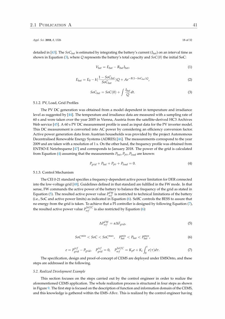
Appl. Sci. 2018, 8, 1326 18 of 32
detailed in [43]. The SoCbat is estimated by integrating the battery’s current (Ibat) on an interval time asshown in Equation (3), where Q represents the battery’s total capacity and SoC(0) the initial SoC:
Vbat = Ebat − Rbat Ibat, (1)
Ebat = E0 − k(1− SoCbat
SoCbat)Q + Ae−B(1−SoCbat)Q, (2)
SoCbat = SoC(0) +∫ Ibat
Qdt. (3)
5.1.2. PV, Load, Grid Profiles
The PV DC generation was obtained from a model dependent in temperature and irradiancelevel as suggested by [44]. The temperature and irradiance data are measured with a sampling rate of60 s and were taken over the year 2005 in Vienna, Austria from the satellite-derived HC3 ArchivesWeb service [45]. A 60 s PV DC measurement profile is used as input data for the PV inverter model.This DC measurement is converted into AC power by considering an efficiency conversion factor.Active power generation data from Austrian households was provided by the project AutonomousDecentralised Renewable Energy Systems (ADRES) [46]. The measurements correspond to the year2009 and are taken with a resolution of 1 s. On the other hand, the frequency profile was obtained fromENTSO-E Netzfrequenz [47] and corresponds to January 2018. The power of the grid is calculatedfrom Equation (4) assuming that the measurements Pbat, Ppv, Pload are known:
Pgrid + Pbat + Ppv + Pload = 0. (4)
5.1.3. Control Mechanism
The CEI 0-21 standard specifies a frequency-dependent active power limitation for DER connectedinto the low-voltage grid [48]. Guidelines defined in that standard are fulfilled in the FW mode. In thatsense, FW commands the active power of the battery to balance the frequency of the grid as stated inEquation (5). The resulted active power value PFW
re f is restricted to technical limitations of the battery(i.e., SoC and active power limits) as indicated in Equation (6). SelfC controls the BESS to assure thatno energy from the grid is taken. To achieve that a PI controller is designed by following Equation (7),the resulted active power value PSel f C
re f is also restricted by Equation (6):
∆PFWre f = α∆Fgrid, (5)
SoCmin < SoC < SoCmax, Pminbat < Pbat < Pmax
bat , (6)
e = Pre fgrid − Pgrid, Pre f
grid = 0, PSel f Cre f = Kpe + Ki
∫ t
0e(τ)dτ. (7)
The specification, design and proof-of-concept of CEMS are deployed under EMSOnto, and thesesteps are addressed in the following.
5.2. Realized Development Example
This section focuses on the steps carried out by the control engineer in order to realize theaforementioned CEMS application. The whole realization process is structured in four steps as shownin Figure 9. The first step is focused on the description of function and information domain of the CEMS,and this knowledge is gathered within the EMS-ABox. This is realized by the control engineer having
2.1 Publication A 41
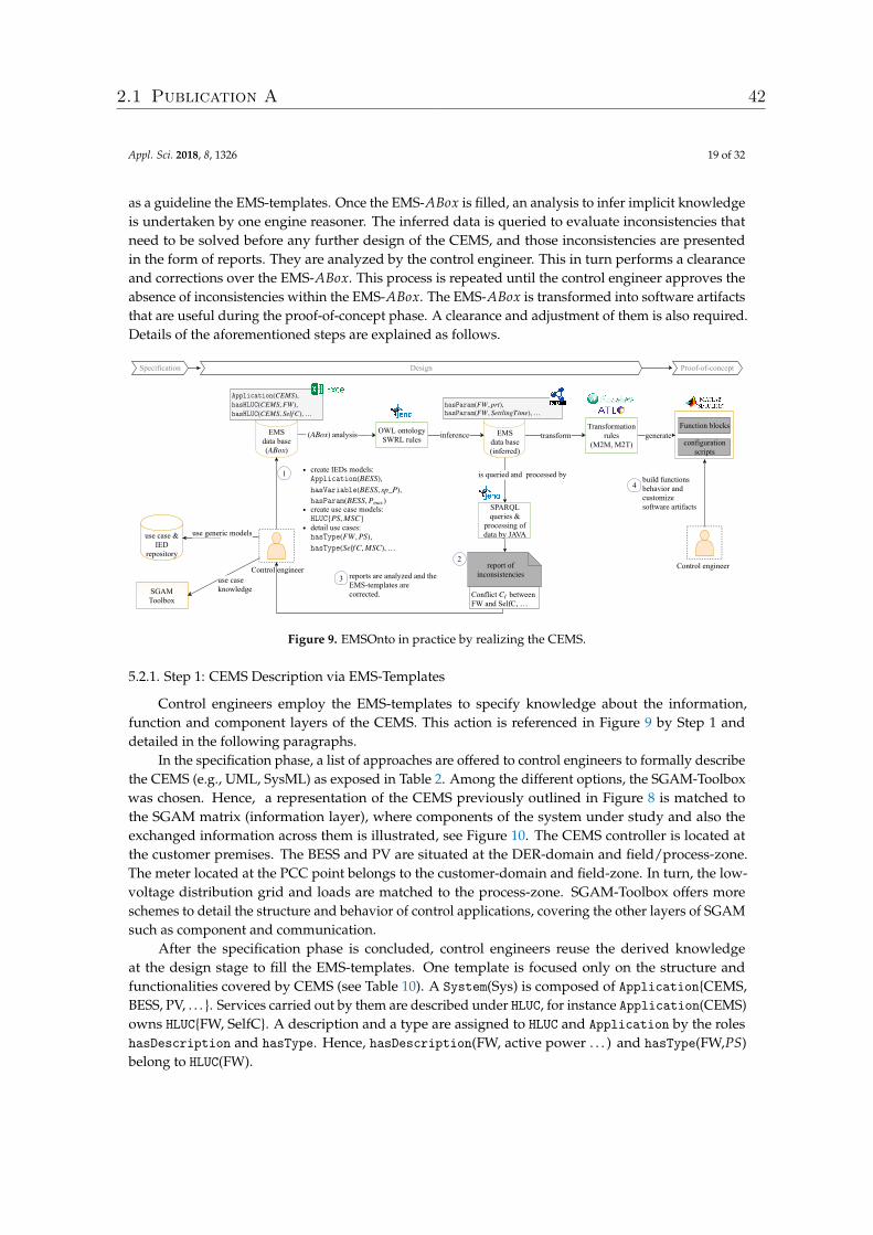
Appl. Sci. 2018, 8, 1326 19 of 32
as a guideline the EMS-templates. Once the EMS-ABox is filled, an analysis to infer implicit knowledgeis undertaken by one engine reasoner. The inferred data is queried to evaluate inconsistencies thatneed to be solved before any further design of the CEMS, and those inconsistencies are presentedin the form of reports. They are analyzed by the control engineer. This in turn performs a clearanceand corrections over the EMS-ABox. This process is repeated until the control engineer approves theabsence of inconsistencies within the EMS-ABox. The EMS-ABox is transformed into software artifactsthat are useful during the proof-of-concept phase. A clearance and adjustment of them is also required.Details of the aforementioned steps are explained as follows.
Conflict between FW and SelfC,
CI
…
SGAM Toolbox
Specification Design Proofofconcept
( ) analysisABox
use case knowledge
EMS data base ( ) ABox
1
inferenceOWL ontology SWRL rules transformEMS
data base (inferred)
is queried and processed by
SPARQLqueries &
processing ofdata by JAVA
reports are analyzed and theEMStemplates arecorrected.
3
report ofinconsistencies
generateTransformation
rules (M2M, M2T)
�����������(CEMS),
�������(CEMS, FW),
�������(CEMS, Self C), …
��������(FW, prt),
��������(FW, SettlingTime), …
Function blocks
configurationscripts
build functionsbehavior andcustomize software artifacts
4
2
use case &IED
repository
create IEDs models:
create use case models:
detail use cases:
�����������(BESS),
�����������(BESS, sp_P),
��������(BESS, )Pmax
����{PS, MSC}
�������(FW, PS),
�������(Self C, MSC), …
Control engineer
use generic models
Control engineer
Figure 9. EMSOnto in practice by realizing the CEMS.
5.2.1. Step 1: CEMS Description via EMS-Templates
Control engineers employ the EMS-templates to specify knowledge about the information,function and component layers of the CEMS. This action is referenced in Figure 9 by Step 1 anddetailed in the following paragraphs.
In the specification phase, a list of approaches are offered to control engineers to formally describethe CEMS (e.g., UML, SysML) as exposed in Table 2. Among the different options, the SGAM-Toolboxwas chosen. Hence, a representation of the CEMS previously outlined in Figure 8 is matched tothe SGAM matrix (information layer), where components of the system under study and also theexchanged information across them is illustrated, see Figure 10. The CEMS controller is located atthe customer premises. The BESS and PV are situated at the DER-domain and field/process-zone.The meter located at the PCC point belongs to the customer-domain and field-zone. In turn, the low-voltage distribution grid and loads are matched to the process-zone. SGAM-Toolbox offers moreschemes to detail the structure and behavior of control applications, covering the other layers of SGAMsuch as component and communication.
After the specification phase is concluded, control engineers reuse the derived knowledgeat the design stage to fill the EMS-templates. One template is focused only on the structure andfunctionalities covered by CEMS (see Table 10). A System(Sys) is composed of Application{CEMS,BESS, PV, . . . }. Services carried out by them are described under HLUC, for instance Application(CEMS)owns HLUC{FW, SelfC}. A description and a type are assigned to HLUC and Application by the roleshasDescription and hasType. Hence, hasDescription(FW, active power . . . ) and hasType(FW,PS)belong to HLUC(FW).
2.1 Publication A 42
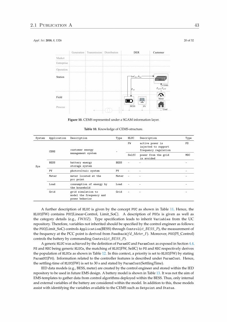
Appl. Sci. 2018, 8, 1326 20 of 32
Generation Transmission Distribution DER Customer
Market
,Pgrid Fgrid
Station
Entreprise
Operation
Field
Process
Pref
So ,Cbat Pbat
BESS PV
Meter
CEMS
Load
Figure 10. CEMS represented under a SGAM information layer.
Table 10. Knowledge of CEMS-structure.
System Application Description Type HLUC Description Type
Sys
CEMS customer energymanagement system -
FW active power isinjected to supportfrequency regulation
PS
SelfC power from the gridis avoided
MSC
BESS battery energystorage system
BESS - - -
PV photovoltaic system PV - - -
Meter meter located at thepcc point
Meter - - -
Load consumption of energy bythe household
Load - - -
Grid grid simulation tomodel the frequency andpower behavior
Grid - - -
A further description of HLUC is given by the concept PUC as shown in Table 11. Hence, theHLUC(FW) contains PUC{Linear-Control, Limit_SoC}. A description of PUCs is given as well asthe category details (e.g., FWHZ). Type specification leads to inherit Variables from the UCrepository. Therefore, variables not inherited should be specified by the control engineer as follows:the PUC(Limit_SoC) controls Application(BESS) through Control(ct_BESS_P), the measurement ofthe frequency at the PCC point is derived from Feedback( f d_Meter_F). Moreover, PUC(PI_Control)controls the battery by commanding Control(ct_BESS_P).
A generic HLUC was achieved by the definition of ParamUC and ParamCont as exposed in Section 4.4.PS and MSC being generic HLUCs, the matching of HLUC{FW, SelfC} to PS and MSC respectively derivesthe population of HLUCs as shown in Table 12. In this context, a priority is set to HLUC(FW) by statingParamUC(Prt). Information related to the controller features is described under ParamCont. Hence,the settling-time of HLUC(FW) is set to 30 s and stated by ParamCont(SettlingTime).
IED data models (e.g., BESS, meter) are created by the control engineer and stored within the IEDrepository to be used in future EMS design. A battery model is shown in Table 13. It was not the aim ofEMS-templates to gather data from control algorithms deployed within the BESS. Thus, only internaland external variables of the battery are considered within the model. In addition to this, those modelsassist with identifying the variables available to the CEMS such as Setpoint and Status.
2.1 Publication A 43
Appl. Sci. 2018, 8, 1326 21 of 32
Table 11. Description of PUCs within HLUC(FW, SelfC).
HLUC PUC Description Type Variable Description Type
FW Linear-Control The active poweris decreased oraugmented linearlyaccording tofrequency variations
FWHZ f d_Meter_F feedback of thefrequency at thePCC point
Feedback
FW Limit_SoC SoC of the batteryis monitored beforesetting Pbat
- ct_BESS_P signal to controlthe active power ofthe battery
Control
SelfC PI_Control PI control isexecuted to keepPgrid equal to zero
- ct_BESS_P signal to controlthe active power ofthe battery
Control
Table 12. Parameters of HLUC(FW).
HLUC Variable Description Type Value Format Unit
FW Prt priority of the use case ParamUC 1 Float -
FW SettlingTime time within the reference value is reached ParamCont 30 Float sec
Table 13. Battery model created by a control engineer.
Application Variable Description Type Value Format Unit
BESS sp_P reference active power to controlcharge/discharge
Setpoint - double kW
Pmax maximum active power Param 4 double kW
The IED repository leverages models from IEC 61850, a large list of function and IED models isdetailed in the standard. A model suitable to PUC(Linear-Control) is extracted from the logical nodeFWHZ exposed in the standard IEC 61850-90-7 [12], resulting in Table 14.
Table 14. PUC(Linear-Control) conception from LN-FWHZ.
PUC Variable Description Type Value Format Unit
Linear-Control Wgra active power gradient in percent of frozenactive power value per Hz
Param 40% Float W/Hz
Linear-Control HzStr delta frequency between start frequencyand nominal frequency
Param 0.04 Float Hz
Linear-Control HzStop delta frequency between stop frequency andnominal frequency
Param 0.01 Float Hz
The detection of certain inconsistencies requires the gathering of extra specific information—forinstance, the detection of conflict CI requires filling Table 15. That conflict looks for a coupling acrossPUCs or HLUCs. The CI identification is based on a proper definition of control goals to be carried outby PUCs. In this light, the variables involved within a control goal are specified (i.e., Manipulated,Control) as follows: PUC(Linear-Control) performs ControlGoal(Cg1), its objective is to manipulatethe power at the electrical connection point of the battery (Pbat). In turn, PUC(PI_Control) satisfiesControlGoal(Cg2) and requires the manipulation of Pgrid. In addition to this, the dependency betweenthe variables Pbat and Pgrid is derived from Pbat + Pload + Pgrid + Ppv = 0. Hence, Linear-Control.Pbataffects the value of PI_Control.Pgrid.
2.1 Publication A 44
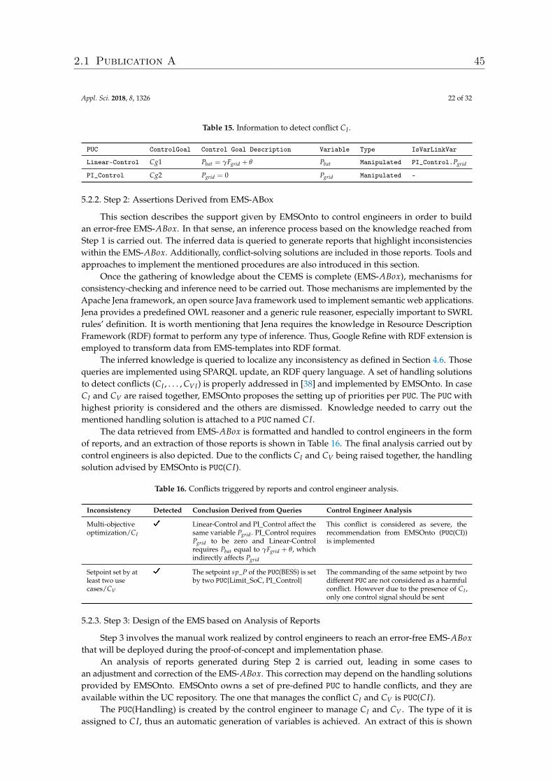
Appl. Sci. 2018, 8, 1326 22 of 32
Table 15. Information to detect conflict CI .
PUC ControlGoal Control Goal Description Variable Type IsVarLinkVar
Linear-Control Cg1 Pbat = γFgrid + θ Pbat Manipulated PI_Control.Pgrid
PI_Control Cg2 Pgrid = 0 Pgrid Manipulated -
5.2.2. Step 2: Assertions Derived from EMS-ABox
This section describes the support given by EMSOnto to control engineers in order to buildan error-free EMS-ABox. In that sense, an inference process based on the knowledge reached fromStep 1 is carried out. The inferred data is queried to generate reports that highlight inconsistencieswithin the EMS-ABox. Additionally, conflict-solving solutions are included in those reports. Tools andapproaches to implement the mentioned procedures are also introduced in this section.
Once the gathering of knowledge about the CEMS is complete (EMS-ABox), mechanisms forconsistency-checking and inference need to be carried out. Those mechanisms are implemented by theApache Jena framework, an open source Java framework used to implement semantic web applications.Jena provides a predefined OWL reasoner and a generic rule reasoner, especially important to SWRLrules’ definition. It is worth mentioning that Jena requires the knowledge in Resource DescriptionFramework (RDF) format to perform any type of inference. Thus, Google Refine with RDF extension isemployed to transform data from EMS-templates into RDF format.
The inferred knowledge is queried to localize any inconsistency as defined in Section 4.6. Thosequeries are implemented using SPARQL update, an RDF query language. A set of handling solutionsto detect conflicts (CI , . . . , CVI) is properly addressed in [38] and implemented by EMSOnto. In caseCI and CV are raised together, EMSOnto proposes the setting up of priorities per PUC. The PUC withhighest priority is considered and the others are dismissed. Knowledge needed to carry out thementioned handling solution is attached to a PUC named CI.
The data retrieved from EMS-ABox is formatted and handled to control engineers in the formof reports, and an extraction of those reports is shown in Table 16. The final analysis carried out bycontrol engineers is also depicted. Due to the conflicts CI and CV being raised together, the handlingsolution advised by EMSOnto is PUC(CI).
Table 16. Conflicts triggered by reports and control engineer analysis.
Inconsistency Detected Conclusion Derived from Queries Control Engineer Analysis
Multi-objectiveoptimization/CI
D Linear-Control and PI_Control affect thesame variable Pgrid. PI_Control requiresPgrid to be zero and Linear-Controlrequires Pbat equal to γFgrid + θ, whichindirectly affects Pgrid
This conflict is considered as severe, therecommendation from EMSOnto (PUC(CI))is implemented
Setpoint set by atleast two usecases/CV
D The setpoint sp_P of the PUC(BESS) is setby two PUC{Limit_SoC, PI_Control}
The commanding of the same setpoint by twodifferent PUC are not considered as a harmfulconflict. However due to the presence of CI ,only one control signal should be sent
5.2.3. Step 3: Design of the EMS based on Analysis of Reports
Step 3 involves the manual work realized by control engineers to reach an error-free EMS-ABoxthat will be deployed during the proof-of-concept and implementation phase.
An analysis of reports generated during Step 2 is carried out, leading in some cases toan adjustment and correction of the EMS-ABox. This correction may depend on the handling solutionsprovided by EMSOnto. EMSOnto owns a set of pre-defined PUC to handle conflicts, and they areavailable within the UC repository. The one that manages the conflict CI and CV is PUC(CI).
The PUC(Handling) is created by the control engineer to manage CI and CV . The type of it isassigned to CI, thus an automatic generation of variables is achieved. An extract of this is shown
2.1 Publication A 45
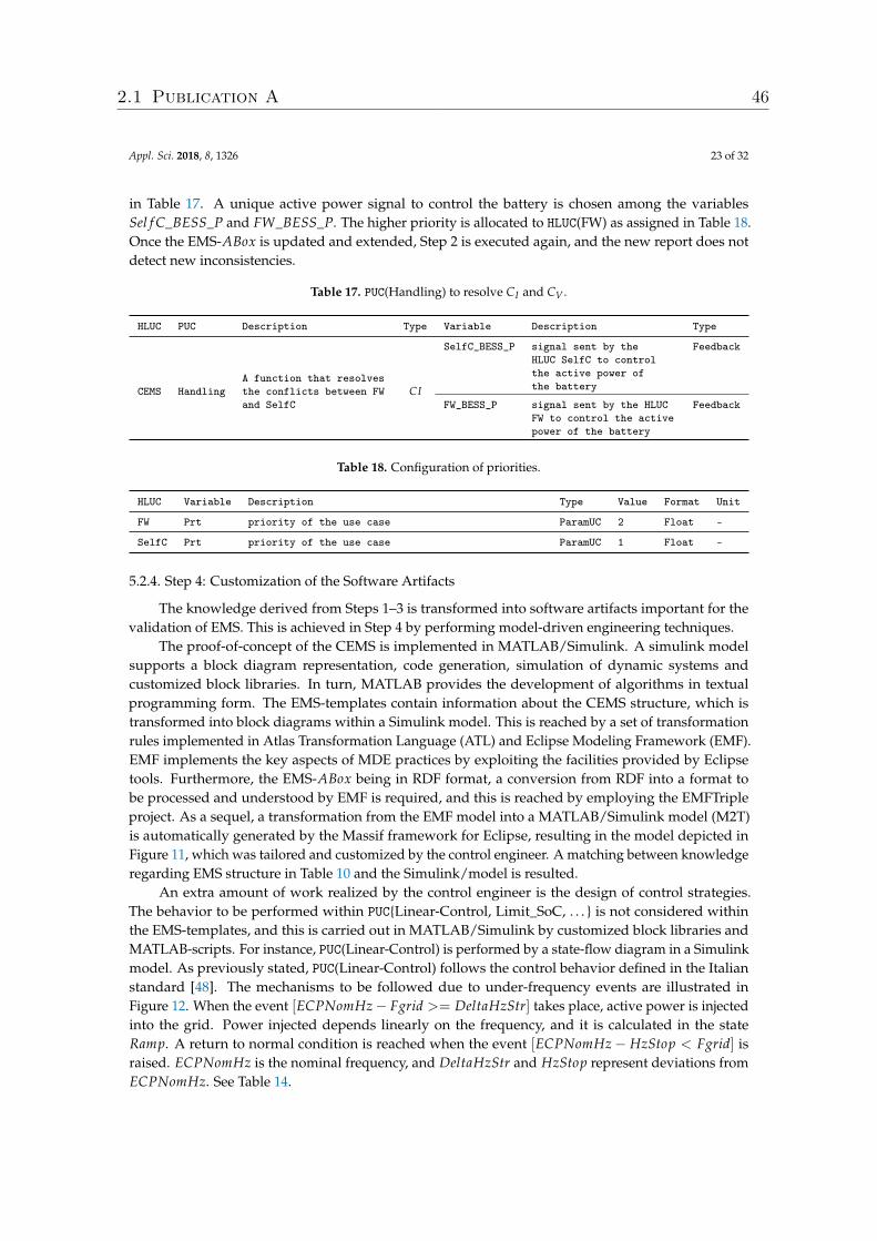
Appl. Sci. 2018, 8, 1326 23 of 32
in Table 17. A unique active power signal to control the battery is chosen among the variablesSel f C_BESS_P and FW_BESS_P. The higher priority is allocated to HLUC(FW) as assigned in Table 18.Once the EMS-ABox is updated and extended, Step 2 is executed again, and the new report does notdetect new inconsistencies.
Table 17. PUC(Handling) to resolve CI and CV .
HLUC PUC Description Type Variable Description Type
CEMS HandlingA function that resolvesthe conflicts between FWand SelfC
CI
SelfC_BESS_P signal sent by theHLUC SelfC to controlthe active power ofthe battery
Feedback
FW_BESS_P signal sent by the HLUCFW to control the activepower of the battery
Feedback
Table 18. Configuration of priorities.
HLUC Variable Description Type Value Format Unit
FW Prt priority of the use case ParamUC 2 Float -
SelfC Prt priority of the use case ParamUC 1 Float -
5.2.4. Step 4: Customization of the Software Artifacts
The knowledge derived from Steps 1–3 is transformed into software artifacts important for thevalidation of EMS. This is achieved in Step 4 by performing model-driven engineering techniques.
The proof-of-concept of the CEMS is implemented in MATLAB/Simulink. A simulink modelsupports a block diagram representation, code generation, simulation of dynamic systems andcustomized block libraries. In turn, MATLAB provides the development of algorithms in textualprogramming form. The EMS-templates contain information about the CEMS structure, which istransformed into block diagrams within a Simulink model. This is reached by a set of transformationrules implemented in Atlas Transformation Language (ATL) and Eclipse Modeling Framework (EMF).EMF implements the key aspects of MDE practices by exploiting the facilities provided by Eclipsetools. Furthermore, the EMS-ABox being in RDF format, a conversion from RDF into a format tobe processed and understood by EMF is required, and this is reached by employing the EMFTripleproject. As a sequel, a transformation from the EMF model into a MATLAB/Simulink model (M2T)is automatically generated by the Massif framework for Eclipse, resulting in the model depicted inFigure 11, which was tailored and customized by the control engineer. A matching between knowledgeregarding EMS structure in Table 10 and the Simulink/model is resulted.
An extra amount of work realized by the control engineer is the design of control strategies.The behavior to be performed within PUC{Linear-Control, Limit_SoC, . . . } is not considered withinthe EMS-templates, and this is carried out in MATLAB/Simulink by customized block libraries andMATLAB-scripts. For instance, PUC(Linear-Control) is performed by a state-flow diagram in a Simulinkmodel. As previously stated, PUC(Linear-Control) follows the control behavior defined in the Italianstandard [48]. The mechanisms to be followed due to under-frequency events are illustrated inFigure 12. When the event [ECPNomHz− Fgrid >= DeltaHzStr] takes place, active power is injectedinto the grid. Power injected depends linearly on the frequency, and it is calculated in the stateRamp. A return to normal condition is reached when the event [ECPNomHz− HzStop < Fgrid] israised. ECPNomHz is the nominal frequency, and DeltaHzStr and HzStop represent deviations fromECPNomHz. See Table 14.
2.1 Publication A 46
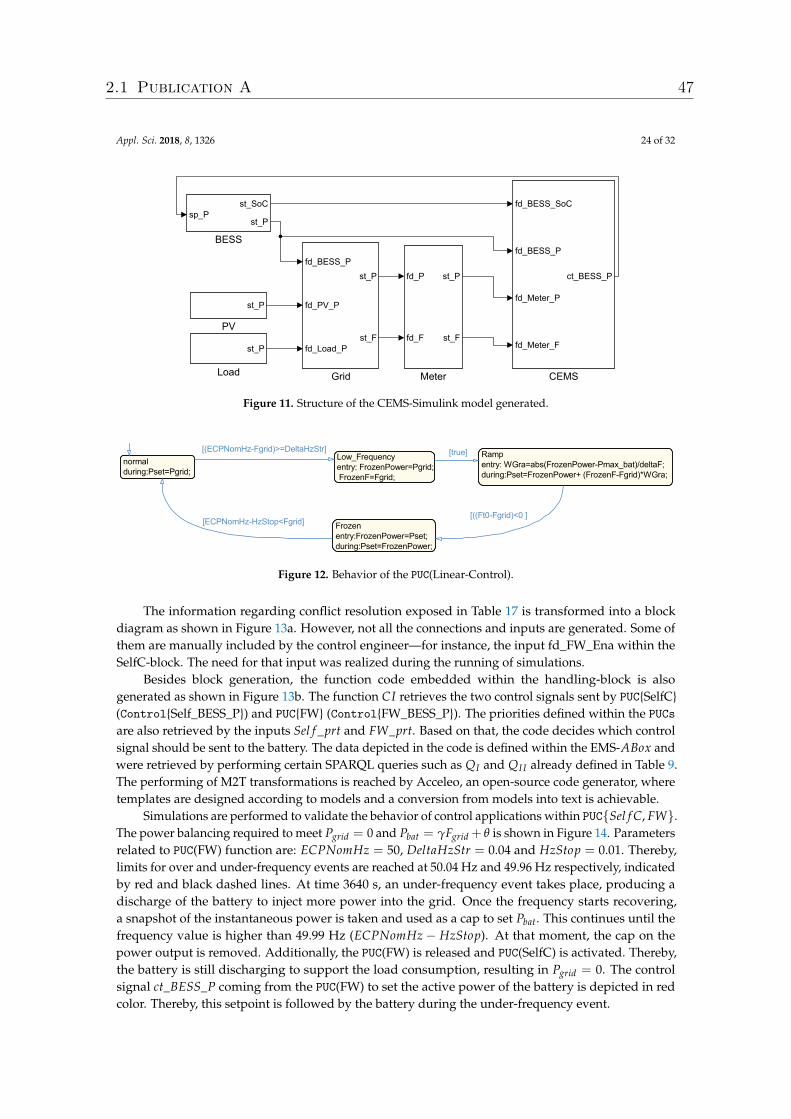
Appl. Sci. 2018, 8, 1326 24 of 32
st_P
Load
st_P
PV
fd_BESS_P
fd_PV_P
fd_Load_P
st_P
st_F
Grid
fd_BESS_SoC
fd_BESS_P
fd_Meter_P
fd_Meter_F
ct_BESS_P
CEMS
sp_Pst_SoC
st_P
BESS
fd_P
fd_F
st_P
st_F
Meter
Figure 11. Structure of the CEMS-Simulink model generated.
normalduring:Pset=Pgrid;
Rampentry: WGra=abs(FrozenPower-Pmax_bat)/deltaF;during:Pset=FrozenPower+ (FrozenF-Fgrid)*WGra;
Low_Frequencyentry: FrozenPower=Pgrid; FrozenF=Fgrid;
Frozenentry:FrozenPower=Pset;during:Pset=FrozenPower;
[((Ft0-Fgrid)<0 ][ECPNomHz-HzStop<Fgrid]
[(ECPNomHz-Fgrid)>=DeltaHzStr] [true]
Figure 12. Behavior of the PUC(Linear-Control).
The information regarding conflict resolution exposed in Table 17 is transformed into a blockdiagram as shown in Figure 13a. However, not all the connections and inputs are generated. Some ofthem are manually included by the control engineer—for instance, the input fd_FW_Ena within theSelfC-block. The need for that input was realized during the running of simulations.
Besides block generation, the function code embedded within the handling-block is alsogenerated as shown in Figure 13b. The function CI retrieves the two control signals sent by PUC{SelfC}(Control{Self_BESS_P}) and PUC{FW} (Control{FW_BESS_P}). The priorities defined within the PUCsare also retrieved by the inputs Sel f _prt and FW_prt. Based on that, the code decides which controlsignal should be sent to the battery. The data depicted in the code is defined within the EMS-ABox andwere retrieved by performing certain SPARQL queries such as QI and QI I already defined in Table 9.The performing of M2T transformations is reached by Acceleo, an open-source code generator, wheretemplates are designed according to models and a conversion from models into text is achievable.
Simulations are performed to validate the behavior of control applications within PUC{Sel f C, FW}.The power balancing required to meet Pgrid = 0 and Pbat = γFgrid + θ is shown in Figure 14. Parametersrelated to PUC(FW) function are: ECPNomHz = 50, DeltaHzStr = 0.04 and HzStop = 0.01. Thereby,limits for over and under-frequency events are reached at 50.04 Hz and 49.96 Hz respectively, indicatedby red and black dashed lines. At time 3640 s, an under-frequency event takes place, producing adischarge of the battery to inject more power into the grid. Once the frequency starts recovering,a snapshot of the instantaneous power is taken and used as a cap to set Pbat. This continues until thefrequency value is higher than 49.99 Hz (ECPNomHz− HzStop). At that moment, the cap on thepower output is removed. Additionally, the PUC(FW) is released and PUC(SelfC) is activated. Thereby,the battery is still discharging to support the load consumption, resulting in Pgrid = 0. The controlsignal ct_BESS_P coming from the PUC(FW) to set the active power of the battery is depicted in redcolor. Thereby, this setpoint is followed by the battery during the under-frequency event.
2.1 Publication A 47
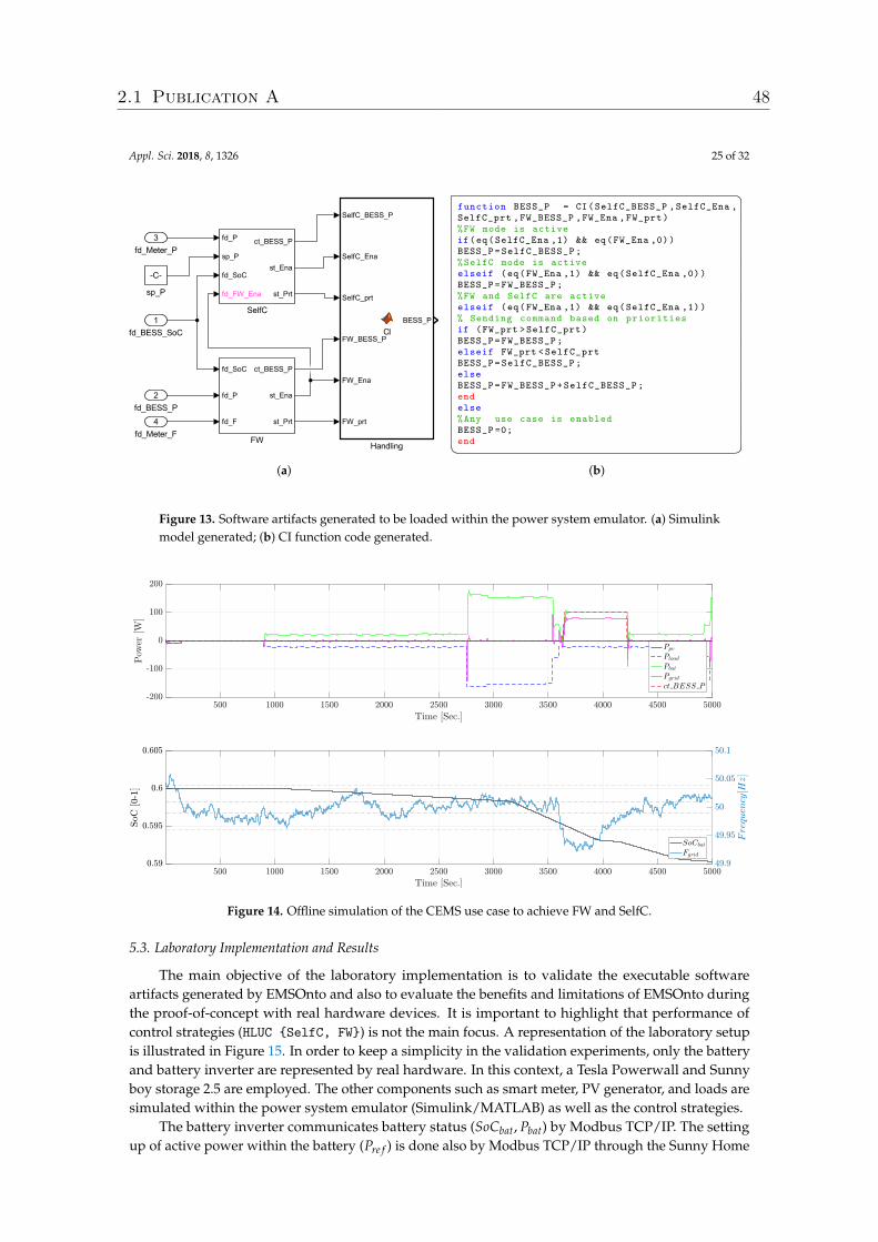
Appl. Sci. 2018, 8, 1326 25 of 32
fd_P
sp_P
fd_SoC
fd_FW_Ena
ct_BESS_P
st_Ena
st_Prt
SelfC
fd_SoC
fd_P
fd_F
ct_BESS_P
st_Ena
st_Prt
FW
SelfC_BESS_P
SelfC_Ena
SelfC_prt
FW_BESS_P
FW_Ena
FW_prt
BESS_P
Handling
1fd_BESS_SoC
2fd_BESS_P
4fd_Meter_F
-C-
sp_P
3fd_Meter_P
(a)
�function BESS_P = CI(SelfC_BESS_P ,SelfC_Ena ,SelfC_prt ,FW_BESS_P ,FW_Ena ,FW_prt)%FW mode is activeif(eq(SelfC_Ena ,1) && eq(FW_Ena ,0))BESS_P=SelfC_BESS_P;%SelfC mode is activeelseif (eq(FW_Ena ,1) && eq(SelfC_Ena ,0))BESS_P=FW_BESS_P;%FW and SelfC are activeelseif (eq(FW_Ena ,1) && eq(SelfC_Ena ,1))% Sending command based on prioritiesif (FW_prt >SelfC_prt)BESS_P=FW_BESS_P;elseif FW_prt <SelfC_prtBESS_P=SelfC_BESS_P;elseBESS_P=FW_BESS_P+SelfC_BESS_P;endelse%Any use case is enabledBESS_P =0;end� �
(b)
Figure 13. Software artifacts generated to be loaded within the power system emulator. (a) Simulinkmodel generated; (b) CI function code generated.
Figure 14. Offline simulation of the CEMS use case to achieve FW and SelfC.
5.3. Laboratory Implementation and Results
The main objective of the laboratory implementation is to validate the executable softwareartifacts generated by EMSOnto and also to evaluate the benefits and limitations of EMSOnto duringthe proof-of-concept with real hardware devices. It is important to highlight that performance ofcontrol strategies (HLUC {SelfC, FW}) is not the main focus. A representation of the laboratory setupis illustrated in Figure 15. In order to keep a simplicity in the validation experiments, only the batteryand battery inverter are represented by real hardware. In this context, a Tesla Powerwall and Sunnyboy storage 2.5 are employed. The other components such as smart meter, PV generator, and loads aresimulated within the power system emulator (Simulink/MATLAB) as well as the control strategies.
The battery inverter communicates battery status (SoCbat, Pbat) by Modbus TCP/IP. The settingup of active power within the battery (Pre f ) is done also by Modbus TCP/IP through the Sunny Home
2.1 Publication A 48
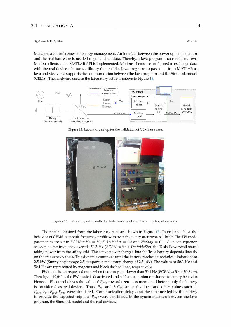
Appl. Sci. 2018, 8, 1326 26 of 32
Manager, a control center for energy management. An interface between the power system emulatorand the real hardware is needed to get and set data. Thereby, a Java program that carries out twoModbus clients and a MATLAB API is implemented. Modbus clients are configured to exchange datawith the real devices. In turn, a library that enables Java programs to pass data from MATLAB toJava and vice versa supports the communication between the Java program and the Simulink model(CEMS). The hardware used in the laboratory setup is shown in Figure 16.
Grid
Battery (Tesla Powerwall)
So ,Cbat Pbat
SunnyHomeManager
Battery inverter (Sunny boy storage 2.5)
Modbusclient
Modbusclient Matlab
engine API
Matlab/Simulink (CEMS)
Pref
So ,Cbat Pbat
Pref
PC basedSpeedwire Modbus TCP/IP
Java program
Figure 15. Laboratory setup for the validation of CEMS use case.
Figure 16. Laboratory setup with the Tesla Powerwall and the Sunny boy storage 2.5.
The results obtained from the laboratory tests are shown in Figure 17. In order to show thebehavior of CEMS, a specific frequency profile with over-frequency occurrences is built. The FW modeparameters are set to ECPNomHz = 50, DeltaHzStr = 0.3 and HzStop = 0.1. As a consequence,as soon as the frequency exceeds 50.3 Hz (ECPNomHz + DeltaHzStr), the Tesla Powerwall startstaking power from the utility grid. The active power charged into the Tesla battery depends linearlyon the frequency values. This dynamic continues until the battery reaches its technical limitations at2.5 kW (Sunny boy storage 2.5 supports a maximum charge of 2.5 kW). The values of 50.3 Hz and50.1 Hz are represented by magenta and black dashed lines, respectively.
FW mode is not requested more when frequency gets lower than 50.1 Hz (ECPNomHz + HzStop).Thereby, at 40,640 s, the FW mode is deactivated and self-consumption conducts the battery behavior.Hence, a PI control drives the value of Pgrid towards zero. As mentioned before, only the batteryis considered as real-device. Thus, Pbat and SoCbat are real-values, and other values such asPload, Ppv, Pgrid, Fgrid were simulated. Communication delays and the time needed by the batteryto provide the expected setpoint (Pre f ) were considered in the synchronization between the Javaprogram, the Simulink model and the real devices.
2.1 Publication A 49
Appl. Sci. 2018, 8, 1326 27 of 32
The lab tests point out the benefits of EMSOnto at the proof-of-concept stage and motivatethe extension of EMSOnto features. In that sense, benefits lie in the formal structure behind a UCrepresentation. Thereby, the parameters such as HzStop and DeltaHzStr to be tuned within use caseswere rapidly identified. On the other hand, conception of EMSOnto tackles information and functiondomain but not communication domain, which should be also supported. In that sense, manualwork performed by control engineers to implement communication interfaces may be reduced byextending EMSOnto. For instance, an automatic generation and configuration of Modbus clients couldbe achieved. On top of that, the mapping of variables between MATLAB/Simulink and Modbusclients could also be covered. In addition to this, improvements such as the extension of the batterymodel presented in Table 13 with the information of Modbus registers are highly recommended.
Figure 17. Real measurements (Pbat, SoCbat) and simulated values to perform FW and SelfC.
5.4. Evaluation of Requirements and Open Issues
EMSOnto is conceived under the fulfillment of requirements R1–R4. As a result, this approachclaims to support control engineers during the design of EMS applications. In order to demonstrateand evaluate it, a use case example (CEMS) is designed and validated. This section analyzes how farthe initial stated requirements (R1-R4) were satisfied.
Repository based on SGAM and IEC 61850. R1 requires benefitting from existent smart griddata models. Hence, EMS-ontology is conceived under the standards IEC 61850 and SGAM. This OWLontology defines the structure of spreadsheet templates, which facilitate the creation of pre-definedmodels (e.g., battery inverter [19] and frequency-watt [12]) to be stored within the IED and use caserepository. The referred repository is built and available to the control engineer to start the designof EMS applications. In the CEMS example, the PUC(Linear-Control) uses knowledge from a FWHZLogical Node accelerating the collection of CEMS data.
EMS-ontology and EMS-templates. R2 searches for an ontology that reflects a commonunderstanding of multi-functional BESS. Thereby, a pattern that models different BESS use cases(UC1–UC5) is established resulting in EMS-ontology. The proposed OWL ontology was used to detailfunctions, parameters and information flows within the CEMS use case. This demonstrates that rolesand concepts defined in the scope of EMS-ontology are appropriate for EMS description. Populationof the ontology is achieved by filling out EMS-templates. Control engineers became familiar with thismethod quite fast, demonstrating that it is a good practice in gathering and documenting of data at thedesign phase. A feature not supported by the approaches presented in Table 2.
2.1 Publication A 50
Appl. Sci. 2018, 8, 1326 28 of 32
A benefit derived from ontologies is the extraction of data from ABox by means of queries.In that sense, once the filling process of EMS-templates is complete, a set of reports to determineEMS functional capabilities can be queried by an external system (e.g., EMO) (see Table 9). However,it is worth noting that information in the design phase may evolve during the proof-of-concept phase(e.g., a signal f d_FW_Ena was included during the validation of the CEMS). Hence, the final state of theEMS knowledge may differ from the information gathered at design time. Thus, a reverse engineeringprocess [49] between the design and proof-of-concept stage is suggested to keep EMS data updated.
As mentioned before, the conception of EMS-ontology is aligned to the broadly recognized SGAMand IEC 61850 data models. Nevertheless, interoperability between EMSOnto and information modelssuch as CIM and OPC UA should also be considered since they are strongly recommended in thesemantics for smart grids [50].
Detection and Handling of Conflicts. R3 requires the implementation of the study [38] to supportthe design of EMS. To achieve the aforementioned, EMS-ontology and the OWL ontology proposedin [38] are aligned. Furthermore, EMS-templates are suggested to gather information mainly importantfor conflict identification. As a consequence, an error-free EMS-ABox is achieved before starting anyimplementation of the control applications. This was exemplified by the CEMS, where conflicts CIand CV were detected and the handling solution proposed by EMSOnto was considered in order tocorrect the CEMS design. Nevertheless, other kinds of inconsistencies not covered by EMSOnto maybe raised during the EMS operation such as an erroneous sensor (i.e., smart meter), a measurementsignal with a low sampling rate or the setting up of out-of-range values into the BESS inverter. Thoseinconsistencies were not considered by EMSOnto, in order to detect them an observation of states overtime is necessary. This would require bringing the concept of temporal logic and concrete logic intodescription logic as performed in [51].
Code and Model Generation. Generation of software artifacts that support the proof-of-conceptand implementation phases are required in R4. Hence, code important to the proof-of-conceptstage is automatically generated. This involves the creation of M2M and M2T transformations fromEMS-templates into a specific platform tool. On that basis, MATLAB code and a Simulink model weregenerated and upload into a MATLAB/Simulink project for CEMS validation purposes. A benefitfrom that is the reduction of errors susceptible to be introduced during the implementation of controlapplications. Moreover, the software artifacts generated were integrated in offline simulations andhardware-in-the-loop tests, contributing to an acceleration of the development process.
Code and models generation were imported in a power system emulator (i.e., MATLAB/Simulink).Nevertheless, other tools such as co-simulators and communication network simulators are also importantduring the proof-of-concept stage. Thereby, the adaptability of EMSOnto with other tools is contemplatedas future work.
A complete EMS implementation requires the establishment of control algorithms’ behavior.However, it was not the aim of EMSOnto to model the behavior of BESS use cases. A comparison andanalysis of smart grid and automation approaches in Section 3.2 show that supports for implementingsystem behavior are available (i.e., MATLAB, IEC 61499 and IEC 61131-3). Thus, to reach a fullimplementation of EMS, the complement of EMSOnto with other existent smart grids and automationapproaches is necessary.
6. Conclusions
A BESS provides support to many stakeholders of the grid going from end-user, distribution andtransmission system operator to EMO. This support may require the deployment of a large set of usecases into an EMS. Such a development process is surrounded by different issues such as flexibility,complexity, overlapping and interoperability. Mechanisms to overcome the mentioned issues arestudied in this paper; as a result, a framework (i.e., EMSOnto) to support control engineers during thedesign and proof-of-concept of EMS control applications is achieved.
2.1 Publication A 51
Appl. Sci. 2018, 8, 1326 29 of 32
A common understanding about EMS control applications is reached, resulting in the conceptionof an OWL ontology called EMS-ontology, which focuses on EMS structure and information exchangedacross the EMS control architecture. Thereby, EMS-ontology is inspired from broadly accepted smartgrid approaches: SGAM and IEC 61850. On the other hand, the population of the ontology is achievedby filling out spreadsheet templates (i.e., EMS-templates). Those templates ease the gathering ofinformation at the design phase, a feature that is not provided by any of the approaches (see Table 2).Moreover, due to EMS-templates being aligned with smart grid standards, a selection of existingdata models (e.g., LN from IEC 61850) was carried out to pre-fill a database that assists during thecollection of EMS knowledge (use case and IED repository). It is worth mentioning that EMS-templatesdo not contemplate the behavior of control applications. Thus, EMSOnto needs to be supported byautomation approaches such as IEC 61131-3 and IEC 61499 to achieve a full implementation.
Detection of conflicts within BESS control applications was already addressed in [38]. However,control engineers were not encouraged to use the referred study due to the amount of work involvedat the design phase. They argued that conflict issues could be handled by a meticulous study ofthe control application. This encouraged the implementation of [38] within EMSOnto as it containsimportant knowledge of EMS that can be used for the inference of conflicts.
A UC example (i.e., CEMS) is developed under the EMSOnto basis showing the benefits andrestrictions of the framework. Moreover, from that implementation, a list of recommendations forfuture work came out. Hence, it is suggested to interoperate EMSOnto with other power systemtools, in order to perform reverse engineering methodologies for the consistency between the designand implementation phases. Additionally, the use of temporal logic to investigate other kinds ofinconsistencies is also encouraged.
Specific planned future work concentrates its efforts in providing flexibility to EMSOnto andto investigate mechanisms for automating the development process. This contemplates enlargingthe inference of knowledge and generating software artifacts relevant for the implementation stage.Moreover, information sources available at the specification phase such as IED configuration files,information models, etc. will be exploited to enhance the collection of data within the EMS-ABox.
Author Contributions: C.Z. wrote the paper and carried out the conceptualization, investigation and validationof the work. F.P.A., J.K., and T.I.S. participated in the conceptualization of the proposed approach and reviewedthe final manuscript. T.I.S. supervised the overall work.
Funding: This work is partly supported by the Austrian Ministry for Transport, Innovation and Technology(bmvit) and the Austrian Research Promotion Agency (FFG) under the ICT of the Future Programme in the MESSEproject (FFG No. 861265).
Conflicts of Interest: The authors declare no conflict of interest.
Appendix A. TBox of the EMS Ontology
TBox = {System v System u ∃hasApplication.Application
Application v Application u ∃hasHLUC.HLUC
HLUC t PUC v UC, HLUC v HLUC u ∃hasPUC.PUC
BESS t EMS t Load tMeter t Generator v Application
PQ tMSC t PS v HLUC
PUC v PUC u ∃hasPUC.PUC u ∃manipulate.ControlGoal
ControlGoal v ControlGoal u ∃IsFcLinkFc.ControlGoal u ∃hasFctVar.Variable
∃hasVariable.T v (Application t HLUC t PUC)
2.1 Publication A 52
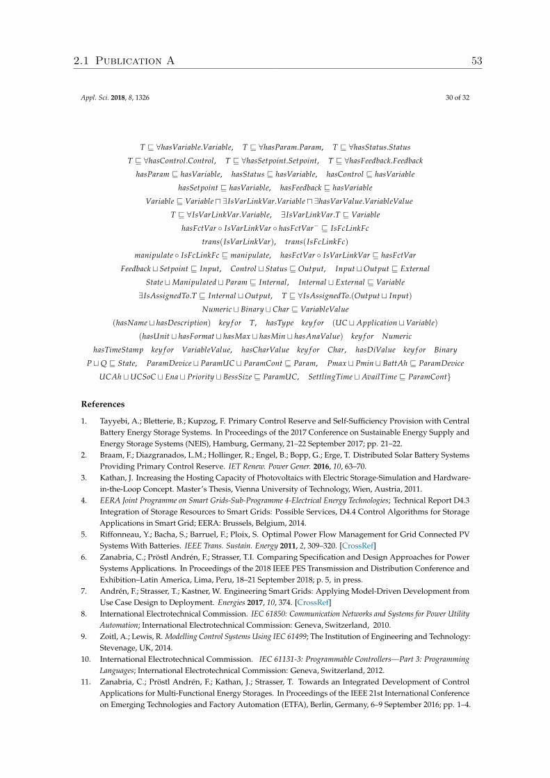
Appl. Sci. 2018, 8, 1326 30 of 32
T v ∀hasVariable.Variable, T v ∀hasParam.Param, T v ∀hasStatus.Status
T v ∀hasControl.Control, T v ∀hasSetpoint.Setpoint, T v ∀hasFeedback.Feedback
hasParam v hasVariable, hasStatus v hasVariable, hasControl v hasVariable
hasSetpoint v hasVariable, hasFeedback v hasVariable
Variable v Variable u ∃IsVarLinkVar.Variable u ∃hasVarValue.VariableValue
T v ∀IsVarLinkVar.Variable, ∃IsVarLinkVar.T v Variable
hasFctVar ◦ IsVarLinkVar ◦ hasFctVar− v IsFcLinkFc
trans(IsVarLinkVar), trans(IsFcLinkFc)
manipulate ◦ IsFcLinkFc v manipulate, hasFctVar ◦ IsVarLinkVar v hasFctVar
Feedback t Setpoint v Input, Control t Status v Output, Input tOutput v External
State tManipulated t Param v Internal, Internal t External v Variable
∃IsAssignedTo.T v Internal tOutput, T v ∀IsAssignedTo.(Output t Input)
Numeric t Binary t Char v VariableValue
(hasName t hasDescription) key f or T, hasType key f or (UC t Application tVariable)
(hasUnit t hasFormat t hasMax t hasMin t hasAnaValue) key f or Numeric
hasTimeStamp key f or VariableValue, hasCharValue key f or Char, hasDiValue key f or Binary
P tQ v State, ParamDevice t ParamUC t ParamCont v Param, Pmax t Pmin t BattAh v ParamDevice
UCAh tUCSoC t Ena t Priority t BessSize v ParamUC, SettlingTime t AvailTime v ParamCont}
References
1. Tayyebi, A.; Bletterie, B.; Kupzog, F. Primary Control Reserve and Self-Sufficiency Provision with CentralBattery Energy Storage Systems. In Proceedings of the 2017 Conference on Sustainable Energy Supply andEnergy Storage Systems (NEIS), Hamburg, Germany, 21–22 September 2017; pp. 21–22.
2. Braam, F.; Diazgranados, L.M.; Hollinger, R.; Engel, B.; Bopp, G.; Erge, T. Distributed Solar Battery SystemsProviding Primary Control Reserve. IET Renew. Power Gener. 2016, 10, 63–70.
3. Kathan, J. Increasing the Hosting Capacity of Photovoltaics with Electric Storage-Simulation and Hardware-in-the-Loop Concept. Master’s Thesis, Vienna University of Technology, Wien, Austria, 2011.
4. EERA Joint Programme on Smart Grids-Sub-Programme 4-Electrical Energy Technologies; Technical Report D4.3Integration of Storage Resources to Smart Grids: Possible Services, D4.4 Control Algorithms for StorageApplications in Smart Grid; EERA: Brussels, Belgium, 2014.
5. Riffonneau, Y.; Bacha, S.; Barruel, F.; Ploix, S. Optimal Power Flow Management for Grid Connected PVSystems With Batteries. IEEE Trans. Sustain. Energy 2011, 2, 309–320. [CrossRef]
6. Zanabria, C.; Pröstl Andrén, F.; Strasser, T.I. Comparing Specification and Design Approaches for PowerSystems Applications. In Proceedings of the 2018 IEEE PES Transmission and Distribution Conference andExhibition–Latin America, Lima, Peru, 18–21 September 2018; p. 5, in press.
7. Andrén, F.; Strasser, T.; Kastner, W. Engineering Smart Grids: Applying Model-Driven Development fromUse Case Design to Deployment. Energies 2017, 10, 374. [CrossRef]
8. International Electrotechnical Commission. IEC 61850: Communication Networks and Systems for Power UtilityAutomation; International Electrotechnical Commission: Geneva, Switzerland, 2010.
9. Zoitl, A.; Lewis, R. Modelling Control Systems Using IEC 61499; The Institution of Engineering and Technology:Stevenage, UK, 2014.
10. International Electrotechnical Commission. IEC 61131-3: Programmable Controllers—Part 3: ProgrammingLanguages; International Electrotechnical Commission: Geneva, Switzerland, 2012.
11. Zanabria, C.; Pröstl Andrén, F.; Kathan, J.; Strasser, T. Towards an Integrated Development of ControlApplications for Multi-Functional Energy Storages. In Proceedings of the IEEE 21st International Conferenceon Emerging Technologies and Factory Automation (ETFA), Berlin, Germany, 6–9 September 2016; pp. 1–4.
2.1 Publication A 53
Appl. Sci. 2018, 8, 1326 31 of 32
12. International Electrotechnical Commission. IEC/TR 61850-90-7—Communication Networks and Systems forPower Utility Automation—Part 90-7: Object Models for Power Converters in Distributed Energy Resources (DER)Systems; International Electrotechnical Commission: Geneva, Switzerland, 2013.
13. Von Appen, J.; Stetz, T.; Braun, M.; Schmiegel, A. Local Voltage Control Strategies for PV Storage Systems inDistribution Grids. IEEE Trans. Smart Grid 2014, 5, 1002–1009. [CrossRef]
14. Faschang, M. Rapid Control Prototyping for Networked Smart Grid Systems Based on an Agile DevelopmentProcess. Ph.D. Thesis, Vienna University of Technology, Wien, Austria, 2015.
15. Faschang, M.; Schwalbe, R.; Einfalt, A.; Mosshammer, R. Controller Hardware in the Loop ApproachesSupporting Rapid Prototyping of Smart Low Voltage Grid Control. In Proceedings of the IEEE PES InnovativeSmart Grid Technologies, Istanbul, Turkey, 12–15 October 2014; pp. 1–5.
16. Andrén, F.; Lehfuss, F.; Strasser, T. A Development and Validation Environment for Real-Time Controller-Hardware-in-the-Loop Experiments in Smart Grids. Int. J. Distrib. Energy Resour. Smart Grids 2013, 9, 27–50.
17. International Electrotechnical Commission. IEC Smart Grid Standardization Roadmap; International ElectrotechnicalCommission: Geneva, Switzerland, 2013.
18. Uslar, M.; Specht, M.; Rohjans, S.; Trefke, J.; González, J.M. The Common Information Model CIM: IEC 61968/61970and 62325-A Practical Introduction to the CIM; Springer Science & Business Media: Berlin, Germany, 2012;Volume 66.
19. International Electrotechnical Commission (IEC). Communication Networks and Systems in Substations–Part 7-420:Communications Systems for Distributed Energy Resources (DER)–Logical Nodes; International ElectrotechnicalCommission: Geneva, Switzerland, 2006.
20. Mahnke, W.; Leitner, S.H.; Damm, M. OPC Unified Architecture; Springer: Berlin, Germany, 2009.21. Weilkiens, T. Systems Engineering with SysML/UML: Modeling, Analysis, Design; Elsevier: New York, NY,
USA, 2011.22. Tornelli, C.; Radaelli, L.; Rikos, E.; Uslar, M. WP 4 Fully Interoperable Systems. Deliverable R4.1: Description
of the Methodology for the Detailed Functional Specification of the ELECTRA Solutions; Technical Report;European Educational Research Association: Berlin, Germany, 2015.
23. International Electrotechnical Commission (IEC). IEC 62559-2 Use Case Methodology-Part2: Definition of theTemplates for Use Cases, Actor List and Requirement List; IEC: Geneva, Switzerland, 2015.
24. CEN-CENELEC-ETSI Smart Grid Coordination Group. Reference Architecture for the Smart Grid; Technical Report;CEN-CENELEC-ETSI Smart Grid Coordination Group: Brussels, Belgium, 2012.
25. Dänekas, C.; Neureiter, C.; Rohjans, S.; Uslar, M.; Engel, D. Towards a Model-Driven-Architecture Process forSmart Grid Projects. In Digital Enterprise Design & Management; Springer: Cham, Switzerland, 2014; Volume 261,pp. 47–58.
26. Hitzler, P.; Krotzsch, M.; Rudolph, S. Foundations Of Semantic Web Technologies; CRC Press: Boca Raton, FL,USA, 2009.
27. Baader, F. The Description Logic Handbook: Theory, Implementation and Applications; Cambridge UniversityPress: Cambridge, UK, 2003.
28. Santodomingo, R.; Rohjans, S.; Uslar, M.; Rodríguez-Mondéjar, J.; Sanz-Bobi, M. Ontology Matching Systemfor Future Energy Smart Grids. Eng. Appl. Artif. Intell. 2014, 32, 242–257. [CrossRef]
29. Dubinin, V.; Vyatkin, V.; Yang, C.W.; Pang, C. Automatic Generation of Automation Applications Basedon Ontology Transformations. In Proceedings of the 2014 IEEE International Conference on EmergingTechnology and Factory Automation (ETFA), Barcelona, Spain, 16–19 September 2014; pp. 1–4.
30. Schachinger, D.; Kastner, W.; Gaida, S. Ontology-Based Abstraction Layer for Smart Grid Interaction inBuilding Energy Management Systems. In Proceedings of the 2016 IEEE International Energy Conference(ENERGYCON), Leuven, Belgium, 4–8 April 2016; pp. 1–6.
31. Zhou, Q.; Natarajan, S.; Simmhan, Y.; Prasanna, V. Semantic Information Modeling for Emerging Applicationsin Smart Grid. In Proceedings of the 2012 Ninth International Conference on Information Technology—NewGenerations, Las Vegas, NV, USA, 16–18 April 2012; pp. 775–782.
32. Samirmi, F.D.; Tang, W.; Wu, Q. Fuzzy Ontology Reasoning for Power Transformer Fault Diagnosis.Adv. Electr. Comput. Eng. 2015, 15, 107–114. [CrossRef]
33. Feldmann, S.; Herzig, S.J.; Kernschmidt, K.; Wolfenstetter, T.; Kammerl, D.; Qamar, A.; Lindemann, U.;Krcmar, H.; Paredis, C.J.J.; Vogel-Heuser, B. Towards Effective Management of Inconsistencies in Model-BasedEngineering of Automated Production Systems. IFAC-PapersOnLine 2015, 48, 916–923. [CrossRef]
2.1 Publication A 54
Appl. Sci. 2018, 8, 1326 32 of 32
34. Brambilla, M.; Cabot, J.; Wimmer, M. Model-Driven Software Engineering in Practice. Synth. Lect. Softw. Eng.2012, 1, 1–182. [CrossRef]
35. Strasser, T.; Rooker, M.; Ebenhofer, G.; Hegny, I.; Wenger, M.; Sünder, C.; Martel, A.; Valentini, A. Multi-DomainModel-Driven Design of Industrial Automation and Control Systems. In Proceedings of the 2008 IEEEInternational Conference on Emerging Technologies and Factory Automation (ETFA), Hamburg, Germany,15–18 September 2008; pp. 1067–1071.
36. Andrén, F.; Strasser, T.; Kastner, W. Model-Driven Engineering Applied to Smart Grid Automation UsingIEC 61850 and IEC 61499. In Proceedings of the Power Systems Computation Conference (PSCC), Wroclaw,Poland, 18–22 August 2014; pp. 1–7.
37. Zanabria, C.; Pröstl Andrén, F.; Kathan, J.; Strasser, T. Approach for Handling Controller Conflicts withinMulti-Functional Energy Storage Systems. CIRED-Open Access Proc. J. 2017, 2017, 1575–1578. [CrossRef]
38. Zanabria, C.; Tayyebi, A.; Pröstl Andrén, F.; Kathan, J.; Strasser, T. Engineering Support for HandlingController Conflicts in Energy Storage Systems Applications. Energies 2017, 10, 1595. [CrossRef]
39. Sirin, E.; Parsia, B.; Grau, B.C.; Kalyanpur, A.; Katz, Y. Pellet: A Practical OWL-DL Reasoner. Web Semant.Sci. Serv. Agents World Wide Web 2007, 5, 51–53. [CrossRef]
40. Working Group Sustainable Processes (SG-CG/SP). CEN-CENELEC-ETSI Smart Grid Coordination Group—Sustainable Processes; Technical Report, CEN-CENELEC-ETSI; Working Group Sustainable Processes (SG-CG/SP):Brussels, Belgium, 2012.
41. International Electrotechnical Commission. Communication Networks and Systems for Power Utility Automation.Part 7-3: Basic Communication Structure-Common Data Classes; International Electrotechnical Commission:Geneva, Switzerland, 2011.
42. Lutz, C.; Areces, C.; Horrocks, I.; Sattler, U. Keys, Nominals, and Concrete Domains. J. Artif. Intell. Res. 2005,23, 667–726.
43. Tremblay, O.; Dessaint, L.A.; Dekkiche, A.I. A Generic Battery Model for the Dynamic Simulation of HybridElectric Vehicles. In Proceedings of the 2007 IEEE Vehicle Power and Propulsion Conference, Arlington, TX,USA, 9–12 September 2007; pp. 284–289.
44. Skoplaki, E.; Palyvos, J. On the Temperature Dependence of Photovoltaic Module Electrical Performance:A Review of Efficiency/Power Correlations. Sol. Energy 2009, 83, 614–624. [CrossRef]
45. HELIOCLIM-3. 2005. Available online: http://www.soda-pro.com/web-services/radiation/helioclim-3-archives-for-free (accessed on 1 January 2015).
46. Autonomous Decentralised Renewable Energy Systems-ADRES. 2009. Available online: https://www.ea.tuwien.ac.at/projects/adres_concept/EN/ (accessed on 1 January 2015).
47. ENTSO-E Netzfrequenz. 2018. Available online: http://www.50hertz.com/de/Maerkte/Regelenergie/Regelenergie-Downloadbereich (accessed on 15 June 2018).
48. Norma Italiana, CEI. Reference Technical Rules for the Connection of Active and Passive Users to the LV ElectricalUtilities (in Italian); Norma Italiana, CEI: Milano, Italy, 2012.
49. Martinez-Gil, J.; Aldana-Montes, J.F. Reverse Ontology Matching. ACM SIGMOD Rec. 2011, 39, 5. [CrossRef]50. Rohjans, S.; Uslar, M.; Juergen Appelrath, H. OPC UA and CIM: Semantics for the Smart Grid. In Proceedings
of the Transmission and Distribution Conference and Exposition, 2010 IEEE PES, New Orleans, LA, USA,19–22 April 2010; pp. 1–8.
51. Baader, F.; Lippmann, M. Runtime Verification Using the Temporal Description Logic ALC-LTL Revisited.J. Appl. Log. 2014, 12, 584–613. [CrossRef]
c© 2018 by the authors. Licensee MDPI, Basel, Switzerland. This article is an open accessarticle distributed under the terms and conditions of the Creative Commons Attribution(CC BY) license (http://creativecommons.org/licenses/by/4.0/).
2.1 Publication A 55

2.2 Publication B 56
2.2 Publication BC. Zanabria, F. Pröstl Andrén , and T. I. Strasser.An Adaptable Engineering Support Framework for Multi-Functional EnergyStorage System Applications.Sustainability, vol. 10, no. 11, 28 pages, 2018.
Own contributionThe problem analysis, selection of an adequate methodology, implementation of a re-search prototype, collection of use cases, implementation of those use cases for validationpurposes, and discussions of the methodology were performed by the applicant. Thestructuring, writing, and editing of the manuscript were also carried out by the ap-plicant. The second and the last author participated in the conceptualization of themethodology. Moreover, they reviewed the manuscript and supervised the overall work.
sustainability
Article
An Adaptable Engineering Support Framework forMulti-Functional Energy Storage System Applications
Claudia Zanabria 1,*, Filip Pröstl Andrén 1 and Thomas I. Strasser 1,2
1 Center for Energy—Electric Energy Systems, AIT Austrian Institute of Technology, 1210 Vienna, Austria;[email protected] (F.P.A.); [email protected] (T.I.S.)
2 Institute of Mechanics and Mechatronics, Vienna University of Technology, 1040 Vienna, Austria* Correspondence: [email protected]
Received: 17 September 2018; Accepted: 31 October 2018; Published: 12 November 2018 �����������������
Abstract: A significant integration of energy storage systems is taking place to offer flexibility toelectrical networks and to mitigate side effects of a high penetration of distributed energy resources.To accommodate this, new processes are needed for the design, implementation, and proof-of-conceptof emerging storage systems services, such as voltage and frequency regulation, and reduction ofenergy costs, among others. Nowadays, modern approaches are getting popular to support engineersduring the design and development process of such multi-functional energy storage systems.Nevertheless, these approaches still lack flexibility needed to accommodate changing practicesand requirements from control engineers and along the development process. With that in mind,this paper shows how a modern development approach for rapid prototyping of multi-functionalbattery energy storage system applications can be extended to provide this needed flexibility. For this,an expert user is introduced, which has the sole purpose of adapting the existing engineering approachto fulfill any new requirements from the control engineers. To achieve this, the expert user combinesconcepts from model-driven engineering and ontologies to reach an adaptable engineering supportframework. As a result, new engineering requirements, such as new information sources and targetplatforms, can be automatically included into the engineering approach by the expert user, providingthe control engineer with further support during the development process. The usefulness of theproposed solution is shown with a selected use case related to the implementation of an applicationfor a battery energy storage system. It demonstrates how the expert user can fully adapt an existingengineering approach to the control engineer’s needs and thus increase the effectiveness of the wholeengineering process.
Keywords: energy management system; energy storage system; semantic web technologies; rules;ontology; engineering support; smart grid architecture model; model driven architecture; IEC 61850;IEC 61499
1. Introduction
The reduction of CO2 emissions is motivating the integration of renewables into powergrids. As a consequence, a higher penetration of distributed generators such as Photovoltaic (PV),wind turbines, and small hydro power stations is taking place [1]. A side effect of this is theperturbation of the power system stability and quality. Those issues were addressed by differentstudies [2], which encourage the use of Battery Energy Storage Systems (BESS). Moreover, BESS canalso support services related to the minimization of supply costs and market integration, amongothers [3]. Consequently, BESS will play a multi-functional role in the near future. The BESS is oftenaccompanied by an Energy Management Systems (EMS) where the BESS’s services and functions arehosted. Hence, the EMS should exchange information with stakeholders and Intelligent Electronic
Sustainability 2018, 10, 4164; doi:10.3390/su10114164 www.mdpi.com/journal/sustainability
2.2 Publication B 57
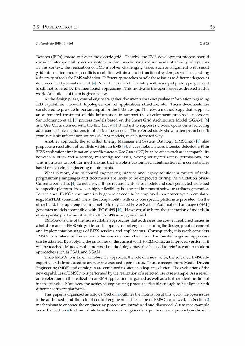
Sustainability 2018, 10, 4164 2 of 28
Devices (IEDs) spread out over the electric grid. Thereby, the EMS development process shouldconsider interoperability across systems as well as evolving requirements of smart grid systems.In this context, the realization of EMS involves challenging tasks, such as alignment with smartgrid information models, conflicts resolution within a multi-functional system, as well as handlinga diversity of tools for EMS validation. Different approaches handle these issues to different degrees asdemonstrated by Zanabria et al. [4]. Nevertheless, a full flexibility within a rapid prototyping contextis still not covered by the mentioned approaches. This motivates the open issues addressed in thiswork. An outlook of them is given below.
At the design phase, control engineers gather documents that encapsulate information regardingIED capabilities, network topologies, control applications structure, etc. Those documents areconsidered to provide important input for the EMS design. Thereby, a methodology that supportsan automated treatment of this information to support the development process is necessary.Santodomingo et al. [5] process models based on the Smart Grid Architecture Model (SGAM) [6]and Use Cases defined with the IEC 62559 [7] standard to support network operators in selectingadequate technical solutions for their business needs. The referred study shows attempts to benefitfrom available information sources (SGAM models) in an automated way.
Another approach, the so called Energy Management System Ontology (EMSOnto) [8] alsoproposes a resolution of conflicts within an EMS [9]. Nevertheless, inconsistencies detected withinBESS applications imply not only conflicts across Use Cases (UC) but also others such as incompatibilitybetween a BESS and a service, misconfigured units, wrong write/red access permissions, etc.This motivates to look for mechanisms that enable a customized identification of inconsistenciesbased on evolving engineering requirements.
What is more, due to control engineering practice and legacy solutions a variety of tools,programming languages and documents are likely to be employed during the validation phase.Current approaches [4] do not answer those requirements since models and code generated were tiedto a specific platform. However, higher flexibility is expected in terms of software artifacts generation.For instance, EMSOnto automatically generates code to be employed in a power system emulator(e.g., MATLAB/Simulink). Here, the compatibility with only one specific platform is provided. On theother hand, the rapid engineering methodology called Power System Automation Language (PSAL)generates models compatible with IEC 61499 [10]. However, also here, the generation of models inother specific platforms rather than IEC 61499 is not guaranteed.
EMSOnto is one of the more suitable approaches that addresses the above mentioned issues ina holistic manner. EMSOnto guides and supports control engineers during the design, proof-of-conceptand implementation stages of BESS services and applications. Consequently, this work considersEMSOnto as reference framework to demonstrate how a flexible and automated engineering processcan be attained. By applying the outcomes of the current work to EMSOnto, an improved version of itwill be reached. Moreover, the proposed methodology may also be used to reinforce other modernapproaches such as PSAL and SGAM.
Since EMSOnto is taken as reference approach, the role of a new actor, the so called EMSOntoexpert user, is introduced to answer the exposed open issues. Thus, concepts from Model-DrivenEngineering (MDE) and ontologies are combined to offer an adequate solution. The evaluation of thenew capabilities of EMSOnto is performed by the realization of a selected use case example. As a result,an acceleration in the realization of EMS applications is gained as well as a further identification ofinconsistencies. Moreover, the achieved engineering process is flexible enough to be aligned withdifferent software platforms.
This paper is organized as follows: Section 2 outlines the motivation of this work, the open issuesto be addressed, and the role of control engineers in the scope of EMSOnto as well. In Section 3mechanisms to enhance the engineering process are introduced and discussed. A use case exampleis used in Section 4 to demonstrate how the control engineer’s requirements are precisely addressed.
2.2 Publication B 58
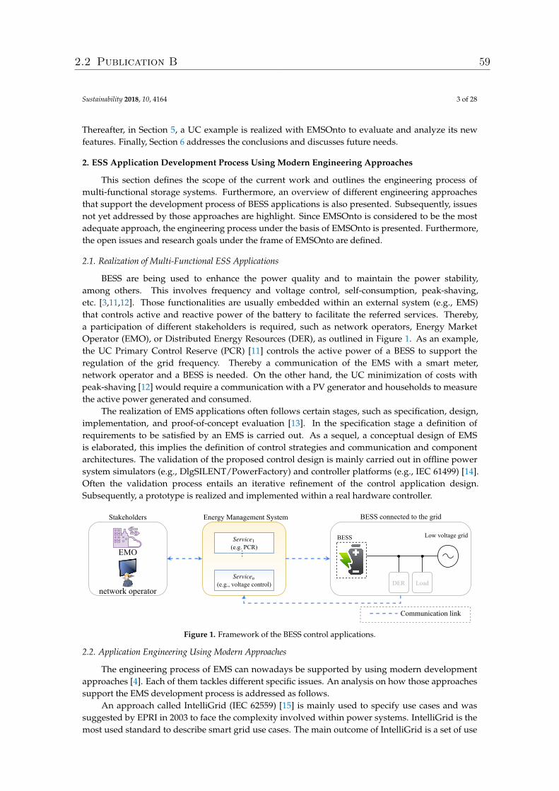
Sustainability 2018, 10, 4164 3 of 28
Thereafter, in Section 5, a UC example is realized with EMSOnto to evaluate and analyze its newfeatures. Finally, Section 6 addresses the conclusions and discusses future needs.
2. ESS Application Development Process Using Modern Engineering Approaches
This section defines the scope of the current work and outlines the engineering process ofmulti-functional storage systems. Furthermore, an overview of different engineering approachesthat support the development process of BESS applications is also presented. Subsequently, issuesnot yet addressed by those approaches are highlight. Since EMSOnto is considered to be the mostadequate approach, the engineering process under the basis of EMSOnto is presented. Furthermore,the open issues and research goals under the frame of EMSOnto are defined.
2.1. Realization of Multi-Functional ESS Applications
BESS are being used to enhance the power quality and to maintain the power stability,among others. This involves frequency and voltage control, self-consumption, peak-shaving,etc. [3,11,12]. Those functionalities are usually embedded within an external system (e.g., EMS)that controls active and reactive power of the battery to facilitate the referred services. Thereby,a participation of different stakeholders is required, such as network operators, Energy MarketOperator (EMO), or Distributed Energy Resources (DER), as outlined in Figure 1. As an example,the UC Primary Control Reserve (PCR) [11] controls the active power of a BESS to support theregulation of the grid frequency. Thereby a communication of the EMS with a smart meter,network operator and a BESS is needed. On the other hand, the UC minimization of costs withpeak-shaving [12] would require a communication with a PV generator and households to measurethe active power generated and consumed.
The realization of EMS applications often follows certain stages, such as specification, design,implementation, and proof-of-concept evaluation [13]. In the specification stage a definition ofrequirements to be satisfied by an EMS is carried out. As a sequel, a conceptual design of EMSis elaborated, this implies the definition of control strategies and communication and componentarchitectures. The validation of the proposed control design is mainly carried out in offline powersystem simulators (e.g., DlgSILENT/PowerFactory) and controller platforms (e.g., IEC 61499) [14].Often the validation process entails an iterative refinement of the control application design.Subsequently, a prototype is realized and implemented within a real hardware controller.
(e.g., voltage control)Service
n
BESS
BESS connected to the grid
Low voltage grid
Energy Management System
DER Loadnetwork operator
EMO(e.g. PCR)Service1
…
Stakeholders
Communication link
Figure 1. Framework of the BESS control applications.
2.2. Application Engineering Using Modern Approaches
The engineering process of EMS can nowadays be supported by using modern developmentapproaches [4]. Each of them tackles different specific issues. An analysis on how those approachessupport the EMS development process is addressed as follows.
An approach called IntelliGrid (IEC 62559) [15] is mainly used to specify use cases and wassuggested by EPRI in 2003 to face the complexity involved within power systems. IntelliGrid is themost used standard to describe smart grid use cases. The main outcome of IntelliGrid is a set of use
2.2 Publication B 59
Sustainability 2018, 10, 4164 4 of 28
case templates that guide engineers during the definition of business cases, use cases and requirements.Those templates are supported with a narrative and visual representation. The process involving therealization of IntelliGrid templates is basically a manual work. This means that information sourcessupporting the EMS specification (e.g., IED’s models, component and communication architectures)are not automatically processed to fill out the templates. Besides this, the consistency of the informationcollected by the referred templates is not verified. This may lead to unattended inconsistent data at thespecification stage.
On the other hand, the Unified Modeling Language (UML) is the most prominent general-purposelanguage to specify and design use cases in an object-oriented approach [16]. UML provides differentstructure (class, component, etc.) and behavior (sequence, activity, etc.) diagrams to allow a completemodeling of use cases. Nowadays, UML is getting more attention also in the domain of power systemto model smart grid solutions [17]. A different approach (SGAM) conceived to model smart gridprojects is recommended by [4]. SGAM provides a set of concepts, coordinated viewpoints anda method to map use cases within a smart grid model. An implementation of SGAM is achieved by theSGAM-Toolbox (SGAM-TB), a UML-based domain specific language available as an extension of theEnterprise Architecture (EA) tool [18]. A drawback of both UML and SGAM is that the informationgathered at the specification phase is not automatically processed to achieve important knowledge forthe design stage. This does not guarantee a consistency between specification and design stages.
A holistic approach called PSAL has as main purpose the modeling of SGAM UCs and at thesame time provide automated support for rapid prototyping. To do this, PSAL provides a formaldomain specific language to describe smart grid systems. PSAL stands out from the previouslymentioned approaches due to the rapid generation of software artifacts (code and communicationconfigurations) offered. However, PSAL does not identify inconsistencies within the planned design.This, in turn, is tackled by EMSOnto, an approach focused on the identification of conflicts and onthe rapid prototyping of multi-functional BESS applications. Nevertheless, EMSOnto lacks flexibilitydue to the restricted set of inconsistencies detection offered. On the other hand, as already mentioned,EMSOnto and PSAL address the rapid generation of software artifacts. However, since the neededtype of software artifacts depend on the UCs to be implemented and on needed legacy solutions,it should be possible to support multiple target platforms. This feature is neither covered by PSALnor EMSOnto. Currently, the generated models and code using PSAL are aligned to the automationstandard IEC 61499 and the communication model IEC 61850. EMSOnto currently only providesgeneration of code for the system simulator MATLAB/Simulink.
The mentioned open issues entail the setting of the following research goals: (i) benefit frominformation sources to automate the realization of design tasks, (ii) facilitate the deduction ofknowledge to be customizable to control engineer’s requirements, and (iii) generate software artifactsto support the whole engineering process. To meet those goals, EMSOnto is taken as the referenceframework due to its completeness and holistic understanding. Hence, the solution proposed in thiswork has been aligned to EMSOnto but should still be applicable not only to EMSOnto but also toother existent and upcoming approaches. The next paragraphs outline EMSOnto and formulate thealready mentioned open issues and research goals under the EMSOnto basis.
2.3. EMSOnto Development Process
An overview of the work performed by control engineers on the frame of EMSOnto is shown inFigure 2. At the specification phase, engineers study the requirements to be fulfilled by the EMS andstarts a rough definition of the behavior and the structure of the EMS control applications. At thisstage, different approaches such as SGAM, Unified Modeling Language (UML) and Systems ModelingLanguage (SysML) for system specification are employed [6,16].
The next step is the design of the EMS, which should be congruent with the specification alreadydefined. To this end, EMSOnto offers spreadsheet templates (EMS-templates) that collect and structurethe EMS’s information. These spreadsheets have headlines with the attributes of functions and
2.2 Publication B 60
Sustainability 2018, 10, 4164 5 of 28
variables created in the scope of the EMS. Moreover, models of IEDs and UCs derived from smartgrids standards (e.g., Common Information Model, IEC 61850) are available within the UC and IEDrepository. Those pre-built models ease the population of EMS-templates and thus compatibility withexistent information models is achieved.
Once the EMS-templates are completely filled a reasoner engine is executed resulting in thederivation of inferred data. The resulted data is queried to identify inconsistencies in the design,a report form gathers those inconsistencies and is handled and analyzed by control engineers.This analysis may lead to adjustments within the planned design. Therefore, at this stageEMS-templates are amended. This process is repeated until control engineers are satisfied withthe resulted design. In consequence, a consistent and less error-prone EMS is achieved before anyimplementation. To support the proof-of-concept a set of software artifacts are made available tocontrol engineers.
report of inconsistencies
population
&modification
inference of knowledge
Database
EMStemplates
Inferred Database
power systemsimulator
software artifacts
configuration file
populatespecificationapproach
Specification Design Proofofconcept, Implementation
populatesmart gridmodels
reports are analyzed
EMStemplates (inferred data)
Control engineer
UC & IEDrepository
use knowledge
data is transformed
customize the software artifacts
controller platform
Figure 2. EMSOnto in practice by control engineers.
2.4. Open Issues
EMSOnto was put in practice by control engineers in the scope of a large range of UCs [8].Those realizations raised a series of requirements understood as open issues within EMSOnto. They aredetailed as follows:
• Information sources are not exploited: At the design stage control engineers dispose documentsthat support the design of EMS. This may correspond to files describing IED capabilities,smart grid use cases, communication networks, information models, etc. (e.g., IEC 61850,IntelliGrid, SGAM) [15,18,19]. Since those files contain requirements and important knowledgefor the design process, control engineers manually need to import selected data into theEMS-templates. This repetitive manual work is time consuming and exposed to human errors.Hence, an automatic exchange between EMS-templates and other information sources is sought.
• Restricted inference: EMSOnto supports the identification of conflicts between use cases. However,this is not the only kind of inconsistency that would harm the suitable operation of EMS.For instance, the setting up of IED registers with a wrong unit value would also impact thecorrect operation. Besides this, the inference of important data to support the design of EMS’scontrol strategies is also missed. Since knowledge to be inferred depends on engineer’s needsa flexible customization of EMSOnto to enlarge inferred knowledge is desired.
• Limited generation of software artifacts: EMS-templates can be automatically transformed intomodels and code compliant with a specific power system simulator (i.e., MATLAB/Simulink).Nevertheless, software platforms to be targeted depend on best practices established for testingand validation. In the power system domain, those platforms involve controller platforms,co-simulation platforms, communication network simulators, etc. (e.g., IEC 61499, Mosaik,
2.2 Publication B 61
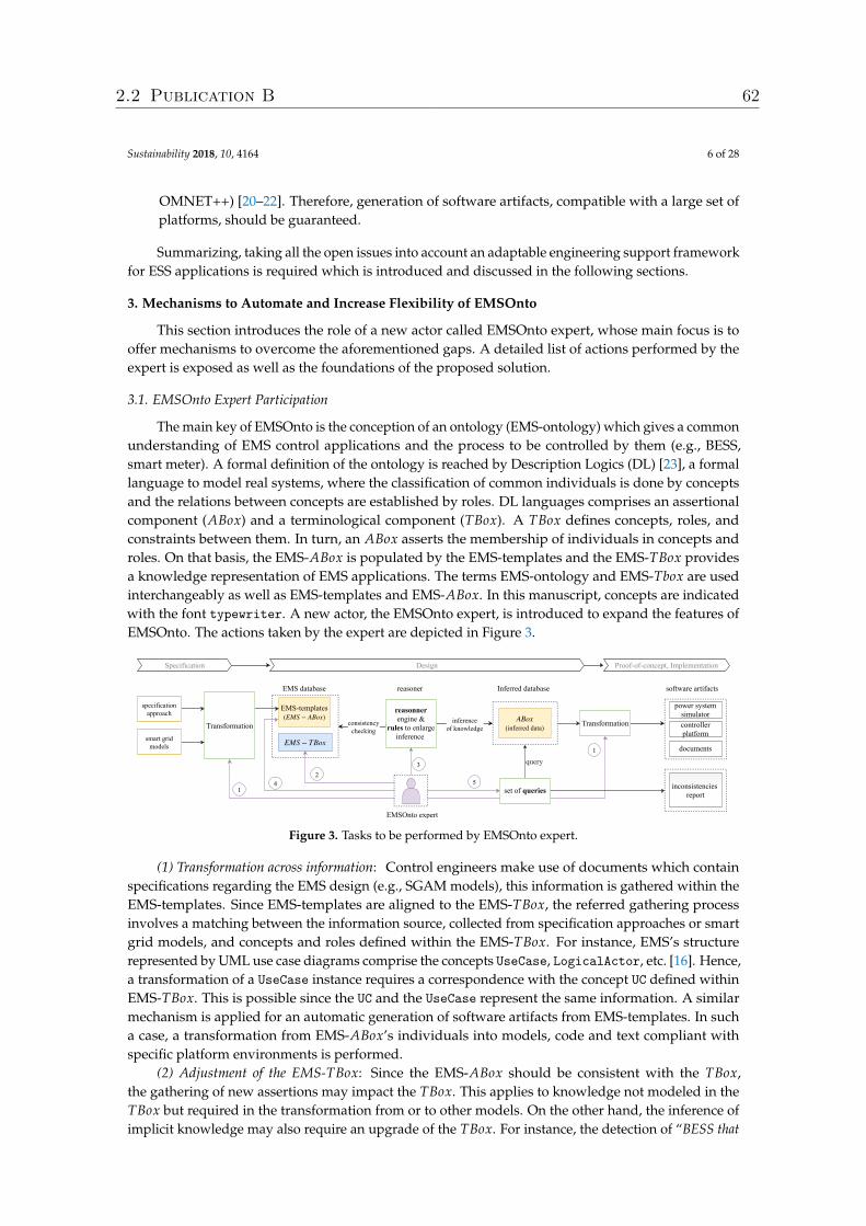
Sustainability 2018, 10, 4164 6 of 28
OMNET++) [20–22]. Therefore, generation of software artifacts, compatible with a large set ofplatforms, should be guaranteed.
Summarizing, taking all the open issues into account an adaptable engineering support frameworkfor ESS applications is required which is introduced and discussed in the following sections.
3. Mechanisms to Automate and Increase Flexibility of EMSOnto
This section introduces the role of a new actor called EMSOnto expert, whose main focus is tooffer mechanisms to overcome the aforementioned gaps. A detailed list of actions performed by theexpert is exposed as well as the foundations of the proposed solution.
3.1. EMSOnto Expert Participation
The main key of EMSOnto is the conception of an ontology (EMS-ontology) which gives a commonunderstanding of EMS control applications and the process to be controlled by them (e.g., BESS,smart meter). A formal definition of the ontology is reached by Description Logics (DL) [23], a formallanguage to model real systems, where the classification of common individuals is done by conceptsand the relations between concepts are established by roles. DL languages comprises an assertionalcomponent (ABox) and a terminological component (TBox). A TBox defines concepts, roles, andconstraints between them. In turn, an ABox asserts the membership of individuals in concepts androles. On that basis, the EMS-ABox is populated by the EMS-templates and the EMS-TBox providesa knowledge representation of EMS applications. The terms EMS-ontology and EMS-Tbox are usedinterchangeably as well as EMS-templates and EMS-ABox. In this manuscript, concepts are indicatedwith the font typewriter. A new actor, the EMSOnto expert, is introduced to expand the features ofEMSOnto. The actions taken by the expert are depicted in Figure 3.
inconsistencies report
inference of knowledge
EMS database
consistency checking
EMStemplates ( ) EMS − ABox
Inferred database
power systemsimulator
software artifacts
controllerplatform
reasoner
specificationapproach
Specification Design Proofofconcept, Implementation
smart gridmodels
Transformation
EMS − TBox
(inferred data)ABox
reasonner engine &
rules to enlarge inference
query
set of queries
Transformation
EMSOnto expert
2
1
3
5
1 documents
4
Figure 3. Tasks to be performed by EMSOnto expert.
(1) Transformation across information: Control engineers make use of documents which containspecifications regarding the EMS design (e.g., SGAM models), this information is gathered within theEMS-templates. Since EMS-templates are aligned to the EMS-TBox, the referred gathering processinvolves a matching between the information source, collected from specification approaches or smartgrid models, and concepts and roles defined within the EMS-TBox. For instance, EMS’s structurerepresented by UML use case diagrams comprise the concepts UseCase, LogicalActor, etc. [16]. Hence,a transformation of a UseCase instance requires a correspondence with the concept UC defined withinEMS-TBox. This is possible since the UC and the UseCase represent the same information. A similarmechanism is applied for an automatic generation of software artifacts from EMS-templates. In sucha case, a transformation from EMS-ABox’s individuals into models, code and text compliant withspecific platform environments is performed.
(2) Adjustment of the EMS-TBox: Since the EMS-ABox should be consistent with the TBox,the gathering of new assertions may impact the TBox. This applies to knowledge not modeled in theTBox but required in the transformation from or to other models. On the other hand, the inference ofimplicit knowledge may also require an upgrade of the TBox. For instance, the detection of “BESS that
2.2 Publication B 62
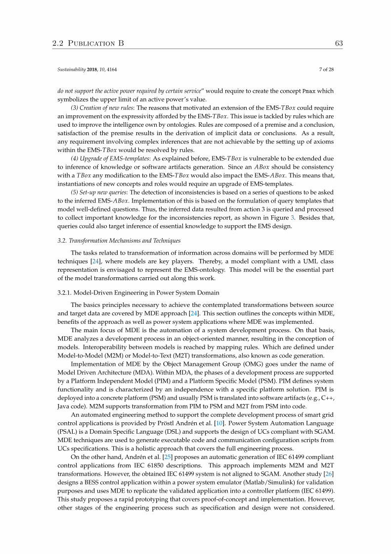
Sustainability 2018, 10, 4164 7 of 28
do not support the active power required by certain service” would require to create the concept Pmax whichsymbolizes the upper limit of an active power’s value.
(3) Creation of new rules: The reasons that motivated an extension of the EMS-TBox could requirean improvement on the expressivity afforded by the EMS-TBox. This issue is tackled by rules which areused to improve the intelligence own by ontologies. Rules are composed of a premise and a conclusion,satisfaction of the premise results in the derivation of implicit data or conclusions. As a result,any requirement involving complex inferences that are not achievable by the setting up of axiomswithin the EMS-TBox would be resolved by rules.
(4) Upgrade of EMS-templates: As explained before, EMS-TBox is vulnerable to be extended dueto inference of knowledge or software artifacts generation. Since an ABox should be consistencywith a TBox any modification to the EMS-TBox would also impact the EMS-ABox. This means that,instantiations of new concepts and roles would require an upgrade of EMS-templates.
(5) Set-up new queries: The detection of inconsistencies is based on a series of questions to be askedto the inferred EMS-ABox. Implementation of this is based on the formulation of query templates thatmodel well-defined questions. Thus, the inferred data resulted from action 3 is queried and processedto collect important knowledge for the inconsistencies report, as shown in Figure 3. Besides that,queries could also target inference of essential knowledge to support the EMS design.
3.2. Transformation Mechanisms and Techniques
The tasks related to transformation of information across domains will be performed by MDEtechniques [24], where models are key players. Thereby, a model compliant with a UML classrepresentation is envisaged to represent the EMS-ontology. This model will be the essential partof the model transformations carried out along this work.
3.2.1. Model-Driven Engineering in Power System Domain
The basics principles necessary to achieve the contemplated transformations between sourceand target data are covered by MDE approach [24]. This section outlines the concepts within MDE,benefits of the approach as well as power system applications where MDE was implemented.
The main focus of MDE is the automation of a system development process. On that basis,MDE analyzes a development process in an object-oriented manner, resulting in the conception ofmodels. Interoperability between models is reached by mapping rules. Which are defined underModel-to-Model (M2M) or Model-to-Text (M2T) transformations, also known as code generation.
Implementation of MDE by the Object Management Group (OMG) goes under the name ofModel Driven Architecture (MDA). Within MDA, the phases of a development process are supportedby a Platform Independent Model (PIM) and a Platform Specific Model (PSM). PIM defines systemfunctionality and is characterized by an independence with a specific platform solution. PIM isdeployed into a concrete platform (PSM) and usually PSM is translated into software artifacts (e.g., C++,Java code). M2M supports transformation from PIM to PSM and M2T from PSM into code.
An automated engineering method to support the complete development process of smart gridcontrol applications is provided by Pröstl Andrén et al. [10]. Power System Automation Language(PSAL) is a Domain Specific Language (DSL) and supports the design of UCs compliant with SGAM.MDE techniques are used to generate executable code and communication configuration scripts fromUCs specifications. This is a holistic approach that covers the full engineering process.
On the other hand, Andrén et al. [25] proposes an automatic generation of IEC 61499 compliantcontrol applications from IEC 61850 descriptions. This approach implements M2M and M2Ttransformations. However, the obtained IEC 61499 system is not aligned to SGAM. Another study [26]designs a BESS control application within a power system emulator (Matlab/Simulink) for validationpurposes and uses MDE to replicate the validated application into a controller platform (IEC 61499).This study proposes a rapid prototyping that covers proof-of-concept and implementation. However,other stages of the engineering process such as specification and design were not considered.
2.2 Publication B 63
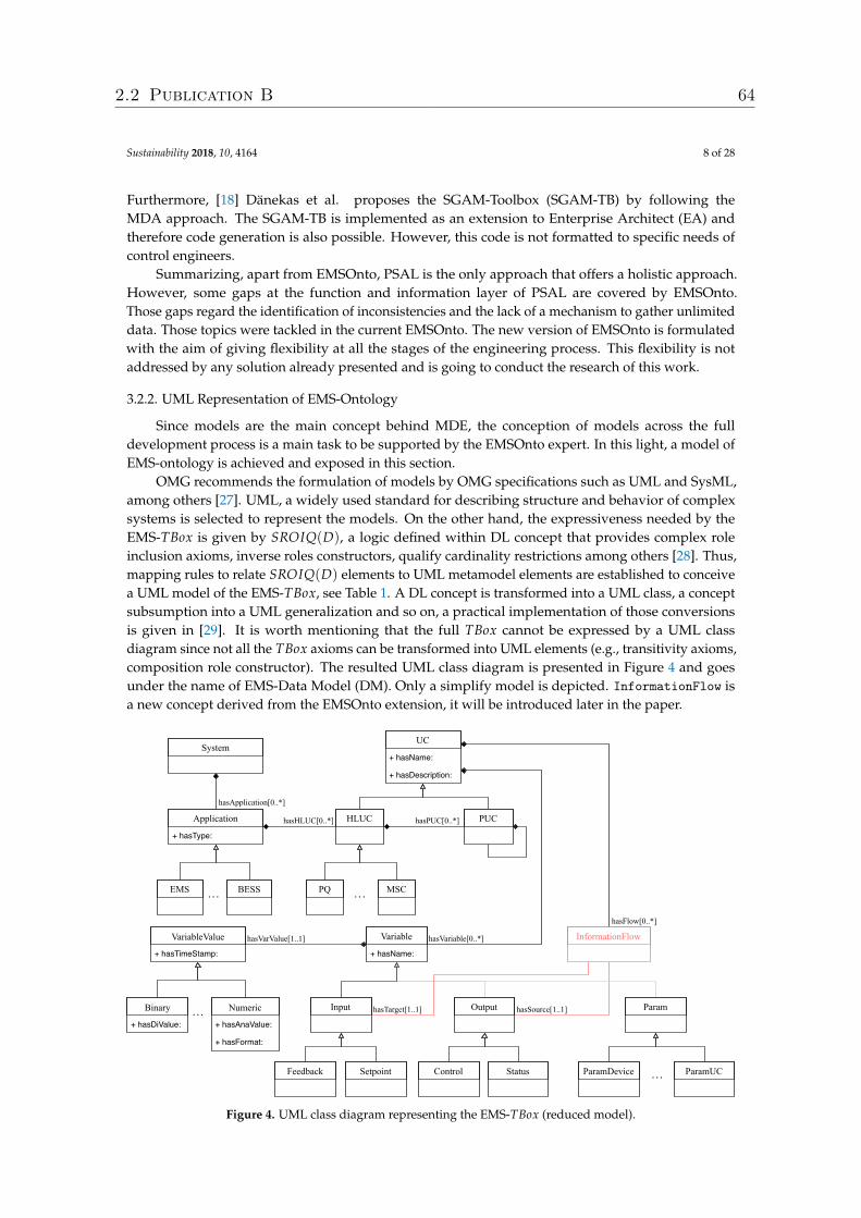
Sustainability 2018, 10, 4164 8 of 28
Furthermore, [18] Dänekas et al. proposes the SGAM-Toolbox (SGAM-TB) by following theMDA approach. The SGAM-TB is implemented as an extension to Enterprise Architect (EA) andtherefore code generation is also possible. However, this code is not formatted to specific needs ofcontrol engineers.
Summarizing, apart from EMSOnto, PSAL is the only approach that offers a holistic approach.However, some gaps at the function and information layer of PSAL are covered by EMSOnto.Those gaps regard the identification of inconsistencies and the lack of a mechanism to gather unlimiteddata. Those topics were tackled in the current EMSOnto. The new version of EMSOnto is formulatedwith the aim of giving flexibility at all the stages of the engineering process. This flexibility is notaddressed by any solution already presented and is going to conduct the research of this work.
3.2.2. UML Representation of EMS-Ontology
Since models are the main concept behind MDE, the conception of models across the fulldevelopment process is a main task to be supported by the EMSOnto expert. In this light, a model ofEMS-ontology is achieved and exposed in this section.
OMG recommends the formulation of models by OMG specifications such as UML and SysML,among others [27]. UML, a widely used standard for describing structure and behavior of complexsystems is selected to represent the models. On the other hand, the expressiveness needed by theEMS-TBox is given by SROIQ(D), a logic defined within DL concept that provides complex roleinclusion axioms, inverse roles constructors, qualify cardinality restrictions among others [28]. Thus,mapping rules to relate SROIQ(D) elements to UML metamodel elements are established to conceivea UML model of the EMS-TBox, see Table 1. A DL concept is transformed into a UML class, a conceptsubsumption into a UML generalization and so on, a practical implementation of those conversionsis given in [29]. It is worth mentioning that the full TBox cannot be expressed by a UML classdiagram since not all the TBox axioms can be transformed into UML elements (e.g., transitivity axioms,composition role constructor). The resulted UML class diagram is presented in Figure 4 and goesunder the name of EMS-Data Model (DM). Only a simplify model is depicted. InformationFlow isa new concept derived from the EMSOnto extension, it will be introduced later in the paper.
System
Application
+ hasType:
HLUC PUC
Variable
Input Output
UC
+ hasName:
+ hasDescription:
EMS BESS PQ MSC
Feedback Setpoint Control Status
+ hasDiValue:
+ hasTimeStamp:
+ hasAnaValue:
+ hasFormat:
+ hasName:
Param
ParamDevice
InformationFlow
ParamUC
hasVariable[0..*]
hasApplication[0..*]
hasVarValue[1..1]
Binary
VariableValue
Numeric
hasHLUC[0..*] hasPUC[0..*]
… …
…
hasFlow[0..*]
hasTarget[1..1] hasSource[1..1]
…
Figure 4. UML class diagram representing the EMS-TBox (reduced model).
2.2 Publication B 64
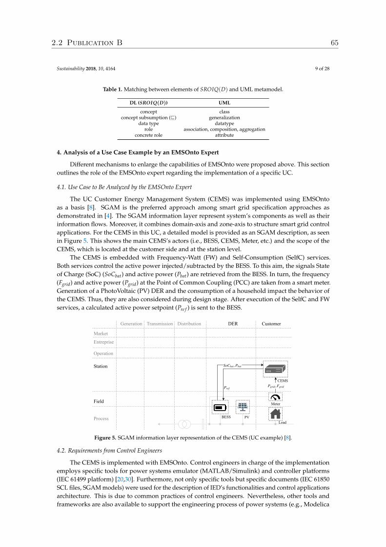
Sustainability 2018, 10, 4164 9 of 28
Table 1. Matching between elements of SROIQ(D) and UML metamodel.
DL (SROIQ(D)) UML
concept classconcept subsumption (v) generalization
data type datatyperole association, composition, aggregation
concrete role attribute
4. Analysis of a Use Case Example by an EMSOnto Expert
Different mechanisms to enlarge the capabilities of EMSOnto were proposed above. This sectionoutlines the role of the EMSOnto expert regarding the implementation of a specific UC.
4.1. Use Case to Be Analyzed by the EMSOnto Expert
The UC Customer Energy Management System (CEMS) was implemented using EMSOntoas a basis [8]. SGAM is the preferred approach among smart grid specification approaches asdemonstrated in [4]. The SGAM information layer represent system’s components as well as theirinformation flows. Moreover, it combines domain-axis and zone-axis to structure smart grid controlapplications. For the CEMS in this UC, a detailed model is provided as an SGAM description, as seenin Figure 5. This shows the main CEMS’s actors (i.e., BESS, CEMS, Meter, etc.) and the scope of theCEMS, which is located at the customer side and at the station level.
The CEMS is embedded with Frequency-Watt (FW) and Self-Consumption (SelfC) services.Both services control the active power injected/subtracted by the BESS. To this aim, the signals Stateof Charge (SoC) (SoCbat) and active power (Pbat) are retrieved from the BESS. In turn, the frequency(Fgrid) and active power (Pgrid) at the Point of Common Coupling (PCC) are taken from a smart meter.Generation of a PhotoVoltaic (PV) DER and the consumption of a household impact the behavior ofthe CEMS. Thus, they are also considered during design stage. After execution of the SelfC and FWservices, a calculated active power setpoint (Pre f ) is sent to the BESS.
Generation Transmission Distribution DER Customer
Market
,Pgrid Fgrid
Station
Entreprise
Operation
Field
Process
Pref
So ,Cbat Pbat
BESS PV
Meter
CEMS
Load
Figure 5. SGAM information layer representation of the CEMS (UC example) [8].
4.2. Requirements from Control Engineers
The CEMS is implemented with EMSOnto. Control engineers in charge of the implementationemploys specific tools for power systems emulator (MATLAB/Simulink) and controller platforms(IEC 61499 platform) [20,30]. Furthermore, not only specific tools but specific documents (IEC 61850SCL files, SGAM models) were used for the description of IED’s functionalities and control applicationsarchitecture. This is due to common practices of control engineers. Nevertheless, other tools andframeworks are also available to support the engineering process of power systems (e.g., Modelica
2.2 Publication B 65
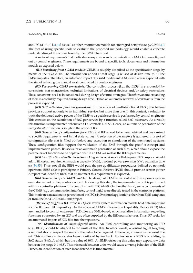
Sustainability 2018, 10, 4164 10 of 28
and IEC 61131-3) [31,32] as well as other information models for smart grid networks (e.g., CIM) [33].The fact of using specific tools to evaluate the proposed methodology would enable a concreteunderstanding of the actions taken by the EMSOnto expert.
A series of requirements that motivates an expansion and customization of EMSOnto were figuredout by control engineers. These requirements are bound to specific tools, documents and informationmodels as exposed below.
(R1) Benefiting from SGAM models: CEMS is roughly described at the specification stage bymeans of the SGAM-TB. The information added at that stage is reused at design time to fill theEMS-templates. Therefore, an automatic import of SGAM models into EMS-templates is expected withthe aim of reducing the manual work conducted by control engineers.
(R2) Discovering CEMS constraints: The controlled process (i.e., the BESS) is surrounded byconstraints that characterizes technical limitations of electrical devices and/or safety restrictions.Those constraints need to be considered during design of control strategies. Therefore, an understandingof them is absolutely required during design time. Hence, an automatic retrieval of constraints from theprocess is expected.
(R3) SoC estimator function generation: In the scope of multi-functional BESS, the batteryprovides support not only to an individual service, but more than one. In this context, a solution totrack the delivered active power of the BESS to a specific service is performed by control engineers.This consists on the calculation of SoC per service by a function called SoC_estimator. As a result,this function is implemented whenever a UC controls a BESS. Hence, an automatic generation of theSoC_estimator function is sough in the scope of R3.
(R4) Generation of configuration files: EMS and IEDs need to be parametrized and customizedto specific requirements and initial state values. A selection of parameters is gathered in a sort ofconfiguration file that is filled out before any execution or simulation of the mentioned systems.These configuration files support the validation of the EMS through the proof-of-concept andimplementation phases. R4 seeks for an automatic generation of such files, which should expose theparameters of functions to be deployed within an EMS as well as the IED’s parameters.
(R5) Identification of batteries mismatching services: A service that request BESS support wouldask to fill certain requirements such as capacity (kWh), maximal power provision (kW), activation time(s) [34,35]. Thus, not all the BESS would pass the pre-qualification procedures defined by networkoperators. BESS able to participate in Primary Control Reserve (PCR) should provide certain power.A report that identifies BESS that do not meet this requirement is expected.
(R6) Generation of IEC 61499 models: The design of CEMS is validated within a power systememulator as part of the proof-of-concept. Following this step, the implementation of it is performedwithin a controller platform fully compliant with IEC 61499. On the other hand, some components ofthe CEMS (e.g., communication interfaces, control logic) were directly tested in the controller platform.This motivates an automatic generation of the IEC 61499 control application either from EMS-templatesor from the MATLAB/Simulink project.
(R7) Benefiting from IEC 61850 ICD files: Power system information models hold data importantfor the IDE and UC repository. In the scope of CEMS, Information Capability Device (ICD) filesare handled to control engineers. ICD files are XML-based, which serialize information regardingfunctions supported by an IED and are often supplied by the IED manufacturer. Thus, R7 seeks foran automated import of ICD files into the repository.
(R8) Identification of misconfigured units: An EMS controlling and monitoring an IED(e.g., BESS) should be aligned to the units of the IED. In other words, a control signal targetinga setpoint should respect the units of the value to be targeted. Otherwise, a wrong value would beset. This applies also to a status been monitored by feedback. For instance, a BESS is providing itsSoC status (SoCbat), which has the value of 80%. An EMS retrieving this value may expect raw databetween the range 0–1 (0.8). This mismatch between units would cause a wrong behavior of the EMS.Hence, an identification of such inconsistencies is fundamental.
2.2 Publication B 66
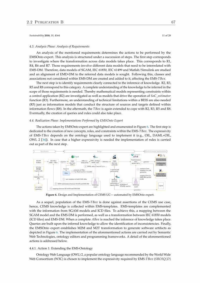
Sustainability 2018, 10, 4164 11 of 28
4.3. Analysis Phase: Analysis of Requirements
An analysis of the mentioned requirements determines the actions to be performed by theEMSOnto expert. This analysis is structured under a succession of steps. The first step correspondsto investigate where the transformation across data models takes place. This corresponds to R1,R4, R6 and R7. Those requirements involve different data models that need to be interrelated withEMS-DM. Therefore, data models of SGAM, IEC 61850, IEC 61499 and Matlab/Simulink are studiedand an alignment of EMD-DM to the referred data models is sought. Following this, classes andassociations not considered within EMS-DM are created and added to it, affecting the EMS-TBox.
The next step is to identify requirements clearly connected to the inference of knowledge. R2, R3,R5 and R8 correspond to this category. A complete understanding of the knowledge to be inferred in thescope of those requirements is needed. Thereby mathematical models representing constraints withina control application (R2) are investigated as well as models that drive the operation of SoC_estimatorfunction (R3). Furthermore, an understanding of technical limitations within a BESS are also needed(R5) just as information models that conduct the structure of sources and targets defined withininformation flows (R8). In the aftermath, the TBox is again extended to cope with R2, R3, R5 and R8.Eventually, the creation of queries and rules could also take place.
4.4. Realization Phase: Implementations Performed by EMSOnto Expert
The actions taken by EMSOnto expert are highlighted and enumerated in Figure 6. The first step isdedicated to the creation of new concepts, roles, and constraints within the EMS-TBox. The expressivityof EMS-TBox depends on the ontology language used to implement it (e.g., OIL, DAML+OIL,OWL 2 [36]). In case that a higher expressivity is needed the implementation of rules is carriedout as part of the next step.
SGAM Toolbox
Specification Design Proofofconcept, Implementation
( ) is analyzed byABox
based on
EMS data base ( ) ABox
inferenceOWL ontology SWRL rules
EMS data base (inferred)
is queried and processed by
generation
SPARQLqueries &
processing ofdata by JAVA
generateTransformation
rules (M2M, M2T)
IEC 61499function blocks
populateSGAM to EMS − TBox
Function blocks
configurationscripts
4 M2M tranformation between SGAM and EMSDM
2
extension of :
TBox
⊤ ⊑ ∀hasConstVar.Variable
5 mappings between IEC61850 and EMSDM
mapping LN to ���
6
definition ofSPARQL queries
creation of newtemplates for codegeneration
mapping betweenEMSDM and IEC61499
7
3 new templates to build EMS ABox
TBox
SWRL rules: Control(?x1) ∧…
1
reportsUC & IEDrepository
ICD file FWHZ
Logical node
EMSOntoexpert
EMSOntoexpert
Figure 6. Design and Implementation of CEMS UC— automated by EMSOnto expert.
As a sequel, population of the EMS-TBox is done against assertions of the CEMS use case,hence, CEMS knowledge is collected within EMS-templates. EMS-templates are complementedwith the information from SGAM models and ICD files. To achieve this, a mapping between theSGAM model and the EMS-DM is performed, as well as a transformation between IEC 61850 models(ICD files) and EMS-DM. When a complete ABox is reached the inference of knowledge takes place.Queries are built upon the inferred knowledge to allow the identification of inconsistencies. Finally,the EMSOnto expert establishes M2M and M2T transformation to generate software artifacts asdepicted in Figure 6. The implementation of the aforementioned actions are carried out by SemanticWeb Technologies, ontology editors and programming frameworks. A detail of the aforementionedactions is addressed below.
4.4.1. Action 1: Extending the EMS-Ontology
Ontology Web Language (OWL) 2, a popular ontology language recommended by the World WideWeb Consortium (W3C) is chosen to implement the expressivity required by EMS-TBox (SROIQ(D)
2.2 Publication B 67
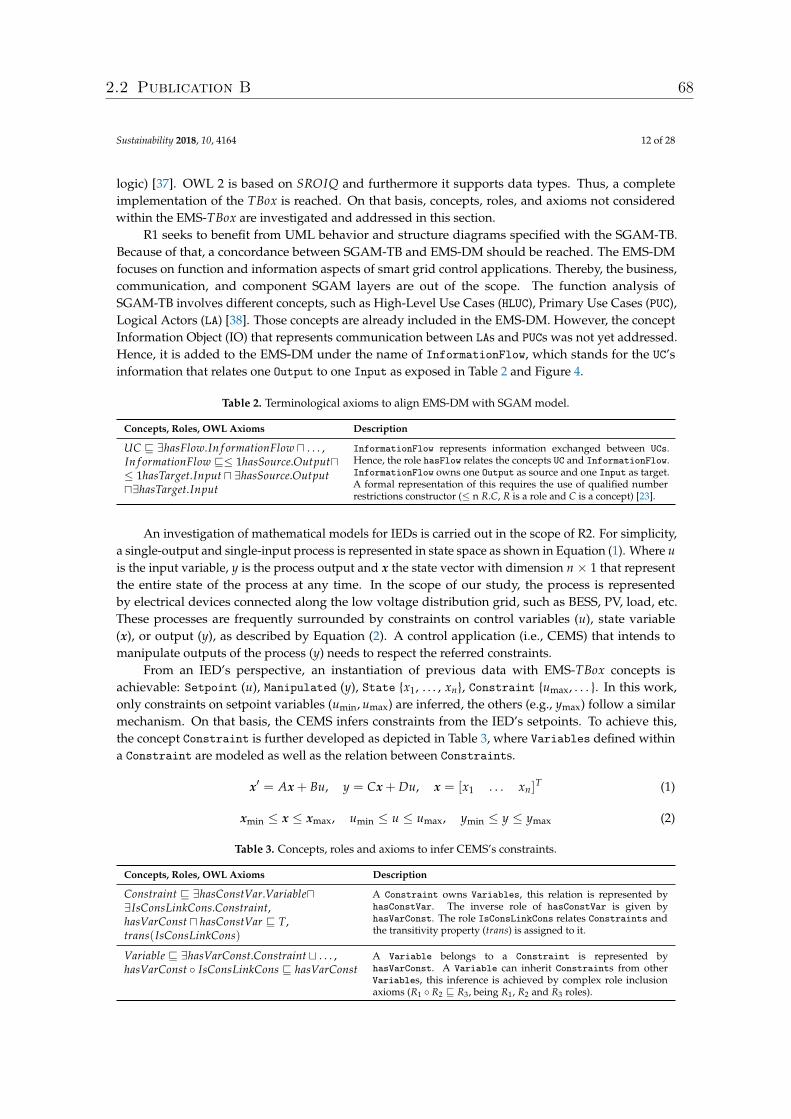
Sustainability 2018, 10, 4164 12 of 28
logic) [37]. OWL 2 is based on SROIQ and furthermore it supports data types. Thus, a completeimplementation of the TBox is reached. On that basis, concepts, roles, and axioms not consideredwithin the EMS-TBox are investigated and addressed in this section.
R1 seeks to benefit from UML behavior and structure diagrams specified with the SGAM-TB.Because of that, a concordance between SGAM-TB and EMS-DM should be reached. The EMS-DMfocuses on function and information aspects of smart grid control applications. Thereby, the business,communication, and component SGAM layers are out of the scope. The function analysis ofSGAM-TB involves different concepts, such as High-Level Use Cases (HLUC), Primary Use Cases (PUC),Logical Actors (LA) [38]. Those concepts are already included in the EMS-DM. However, the conceptInformation Object (IO) that represents communication between LAs and PUCs was not yet addressed.Hence, it is added to the EMS-DM under the name of InformationFlow, which stands for the UC’sinformation that relates one Output to one Input as exposed in Table 2 and Figure 4.
Table 2. Terminological axioms to align EMS-DM with SGAM model.
Concepts, Roles, OWL Axioms Description
UC v ∃hasFlow.In f ormationFlow u . . . ,In f ormationFlow v≤ 1hasSource.Outputu≤ 1hasTarget.Input u ∃hasSource.Outputu∃hasTarget.Input
InformationFlow represents information exchanged between UCs.Hence, the role hasFlow relates the concepts UC and InformationFlow.InformationFlow owns one Output as source and one Input as target.A formal representation of this requires the use of qualified numberrestrictions constructor (≤ n R.C, R is a role and C is a concept) [23].
An investigation of mathematical models for IEDs is carried out in the scope of R2. For simplicity,a single-output and single-input process is represented in state space as shown in Equation (1). Where uis the input variable, y is the process output and x the state vector with dimension n × 1 that representthe entire state of the process at any time. In the scope of our study, the process is representedby electrical devices connected along the low voltage distribution grid, such as BESS, PV, load, etc.These processes are frequently surrounded by constraints on control variables (u), state variable(x), or output (y), as described by Equation (2). A control application (i.e., CEMS) that intends tomanipulate outputs of the process (y) needs to respect the referred constraints.
From an IED’s perspective, an instantiation of previous data with EMS-TBox concepts isachievable: Setpoint (u), Manipulated (y), State {x1, . . . , xn}, Constraint {umax, . . . }. In this work,only constraints on setpoint variables (umin, umax) are inferred, the others (e.g., ymax) follow a similarmechanism. On that basis, the CEMS infers constraints from the IED’s setpoints. To achieve this,the concept Constraint is further developed as depicted in Table 3, where Variables defined withina Constraint are modeled as well as the relation between Constraints.
x′ = Ax + Bu, y = Cx + Du, x = [x1 . . . xn]T (1)
xmin ≤ x ≤ xmax, umin ≤ u ≤ umax, ymin ≤ y ≤ ymax (2)
Table 3. Concepts, roles and axioms to infer CEMS’s constraints.
Concepts, Roles, OWL Axioms Description
Constraint v ∃hasConstVar.Variableu∃IsConsLinkCons.Constraint,hasVarConst u hasConstVar v T,trans(IsConsLinkCons)
A Constraint owns Variables, this relation is represented byhasConstVar. The inverse role of hasConstVar is given byhasVarConst. The role IsConsLinkCons relates Constraints andthe transitivity property (trans) is assigned to it.
Variable v ∃hasVarConst.Constraint t . . . ,hasVarConst ◦ IsConsLinkCons v hasVarConst
A Variable belongs to a Constraint is represented byhasVarConst. A Variable can inherit Constraints from otherVariables, this inference is achieved by complex role inclusionaxioms (R1 ◦ R2 v R3, being R1, R2 and R3 roles).
2.2 Publication B 68
Sustainability 2018, 10, 4164 13 of 28
The generation of the SoC_estimator function is contemplated in R3. Thereby, an analysisof data that conforms such function is carried out. Considering a HLUC controlling the activepower supplied by a BESS, the calculation of HLUC’s SoC (SoChluc) follows the logic in Equation [3].SoChluc depends on the SoC initially assigned to the HLUC (SoCini), the current charged into the BESS(Ibat), as well as the total capacity of the BESS (Qbat) and a portion capacity assigned to the HLUC (Qhluc).The value Ibat is calculated from the active power (Pbat) and the nominal voltage (Vnom) of the battery.A modeling of the mentioned variables results in the following instantiations: State{Vnom, SoC},ParamDevice{SoCini, CAh} and ParamUC(CAh_UC). Nevertheless, a further representation of thosevariables is required, resulting in new concepts. For instance, the concept Vnom represents nominalvoltages and is subsumed by State. A detail of all those new concepts is given in Table 4.
On the other hand, the creation of new roles facilitates the generation of SoC_estimator. Hence,ControlBESS relates a UC controlling a BESS and the concrete role hasI_O facilitates a remote control ofinternal variables defined within the scope of a UC as detailed in Table 4.
SoChluc = SoCini +∫ Ibat
QbatQhluc, Ibat =
PbatVnom
(3)
Table 4. Extension of EMS-TBox to generate SoC_estimator function.
Concepts, Roles, OWL Axioms Description
Vnom t SoC t P t I t · · · v StateVnom and SoC represent a nominal voltage (e.g., Vnom) and a state ofcharge (e.g., SoChluc) respectively. P models an active power (e.g.,Pbat) and I a current value (e.g., Ibat).
SoCini t CAh t · · · v ParamDevice SoCini represents an initial SoC (e.g., SoCini), CAh models the fullcapacity of an energy storage device (e.g., Qbat) .
CAh_UC t · · · v ParamUC Capacity assigned to a UC is represented by CAh_UC (e.g., Qhluc).
Application v ∃IsConnectedTo.Application . . . ,HLUC v ∃ControlBESS.BESS . . .
The role IsConnectedTo relates two applications and the roleControlBESS relates a HLUC that is connected to a BESS.
hasI_O key f or Internal
hasI_O gathers information about whether or not a variable of typeInternal is assigned to an Input or Output. Thereby, variablesaffected by this role are those subsumed by Internal (Param,State, . . . ).
4.4.2. Action 2: Enlargement of Inference Process
The inference of data reached by OWL ontologies can be extended by Semantic Web RuleLanguage (SWRL). This concept is standardized by W3C as language for expressing rules andprovides powerful deductible reasoning mechanisms compared to OWL. SWRL is based on OWLDL, Datalog and Horn-like rules [39]. As a result, the syntax of SWRL is represented by atoms,rule body (antecedent) and rule head (consequent): Atom ∧ Atom ∧ · · · → Atom. If the conditions onthe antecedent hold, then also the conditions in the consequent hold. On that basis, SWRL rules r1and r2 are designed to support the identification of CEMS’s constraints, as shown in Table 5. Where r1deduces Variables assigned to Constraints and r2 infers relations between Constraints.
Table 5. Rules to infer CEMS’s constraints.
SWRL Rules Description
r1: Control(?x1) ∧ IsAssignedTo(?x1, ?s) ∧ Setpoint(?s)∧hasVarConst(?s, ?c1) ∧ Constraint(?c1)→ hasVarConst(?x1, ?c1)r
A Control inherits constraints assignedto the Setpoint that it targets. A setpointvariable ?s owns the constraint ?c1, if ?sis controlled by ?x1, then ?x1 inherits theconstraint ?c1.
r2: Constraint(?c1) ∧ hasConstVar(?c1, ?x1) ∧ IsVarLinkVar(?x1, ?x2)∧Variable(?x1) ∧Variable(?x2) ∧ hasVarConst(?x2, ?c2)→ IsConsLinkCons(?c1, ?c2)
The role IsConsLinkCons is establishedwhen a relation between Costraints isdetected.
2.2 Publication B 69
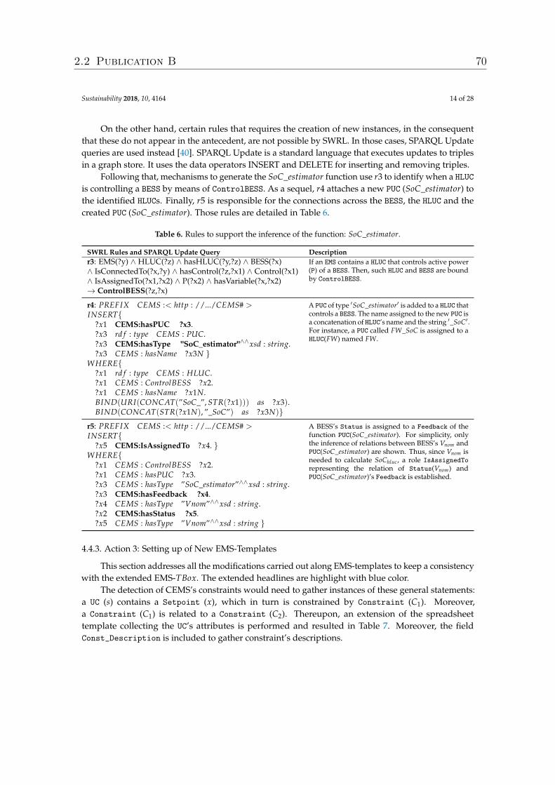
Sustainability 2018, 10, 4164 14 of 28
On the other hand, certain rules that requires the creation of new instances, in the consequentthat these do not appear in the antecedent, are not possible by SWRL. In those cases, SPARQL Updatequeries are used instead [40]. SPARQL Update is a standard language that executes updates to triplesin a graph store. It uses the data operators INSERT and DELETE for inserting and removing triples.
Following that, mechanisms to generate the SoC_estimator function use r3 to identify when a HLUCis controlling a BESS by means of ControlBESS. As a sequel, r4 attaches a new PUC (SoC_estimator) tothe identified HLUCs. Finally, r5 is responsible for the connections across the BESS, the HLUC and thecreated PUC (SoC_estimator). Those rules are detailed in Table 6.
Table 6. Rules to support the inference of the function: SoC_estimator.
SWRL Rules and SPARQL Update Query Descriptionr3: EMS(?y) ∧ HLUC(?z) ∧ hasHLUC(?y,?z) ∧ BESS(?x)∧ IsConnectedTo(?x,?y) ∧ hasControl(?z,?x1) ∧ Control(?x1)∧ IsAssignedTo(?x1,?x2) ∧ P(?x2) ∧ hasVariable(?x,?x2)→ ControlBESS(?z,?x)
If an EMS contains a HLUC that controls active power(P) of a BESS. Then, such HLUC and BESS are boundby ControlBESS.
r4: PREFIX CEMS :< http : //.../CEMS# >INSERT{
?x1 CEMS:hasPUC ?x3.?x3 rd f : type CEMS : PUC.?x3 CEMS:hasType "SoC_estimator"∧∧xsd : string.?x3 CEMS : hasName ?x3N }
WHERE{?x1 rd f : type CEMS : HLUC.?x1 CEMS : ControlBESS ?x2.?x1 CEMS : hasName ?x1N.BIND(URI(CONCAT(”SoC_”, STR(?x1))) as ?x3).BIND(CONCAT(STR(?x1N), ”_SoC”) as ?x3N)}
A PUC of type ′SoC_estimator′ is added to a HLUC thatcontrols a BESS. The name assigned to the new PUC isa concatenation of HLUC’s name and the string ′_SoC′.For instance, a PUC called FW_SoC is assigned to aHLUC(FW) named FW.
r5: PREFIX CEMS :< http : //.../CEMS# >INSERT{
?x5 CEMS:IsAssignedTo ?x4. }WHERE{
?x1 CEMS : ControlBESS ?x2.?x1 CEMS : hasPUC ?x3.?x3 CEMS : hasType ”SoC_estimator”∧∧xsd : string.?x3 CEMS:hasFeedback ?x4.?x4 CEMS : hasType ”Vnom”∧∧xsd : string.?x2 CEMS:hasStatus ?x5.?x5 CEMS : hasType ”Vnom”∧∧xsd : string }
A BESS’s Status is assigned to a Feedback of thefunction PUC(SoC_estimator). For simplicity, onlythe inference of relations between BESS’s Vnom andPUC(SoC_estimator) are shown. Thus, since Vnom isneeded to calculate SoChluc, a role IsAssignedTorepresenting the relation of Status(Vnom) andPUC(SoC_estimator)’s Feedback is established.
4.4.3. Action 3: Setting up of New EMS-Templates
This section addresses all the modifications carried out along EMS-templates to keep a consistencywith the extended EMS-TBox. The extended headlines are highlight with blue color.
The detection of CEMS’s constraints would need to gather instances of these general statements:a UC (s) contains a Setpoint (x), which in turn is constrained by Constraint (C1). Moreover,a Constraint (C1) is related to a Constraint (C2). Thereupon, an extension of the spreadsheettemplate collecting the UC’s attributes is performed and resulted in Table 7. Moreover, the fieldConst_Description is included to gather constraint’s descriptions.
2.2 Publication B 70
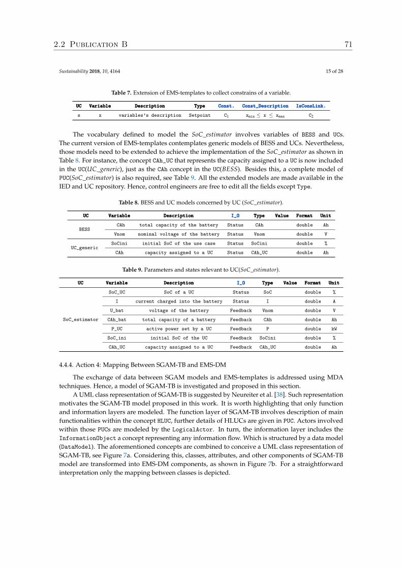
Sustainability 2018, 10, 4164 15 of 28
Table 7. Extension of EMS-templates to collect constrains of a variable.
UCUCUC VariableVariableVariable DescriptionDescriptionDescription TypeTypeType Const.Const.Const. Const_DescriptionConst_DescriptionConst_Description IsConsLink.IsConsLink.IsConsLink.
s x variables’s description Setpoint C1 xmin ≤ x ≤ xmax C2
The vocabulary defined to model the SoC_estimator involves variables of BESS and UCs.The current version of EMS-templates contemplates generic models of BESS and UCs. Nevertheless,those models need to be extended to achieve the implementation of the SoC_estimator as shown inTable 8. For instance, the concept CAh_UC that represents the capacity assigned to a UC is now includedin the UC(UC_generic), just as the CAh concept in the UC(BESS). Besides this, a complete model ofPUC(SoC_estimator) is also required, see Table 9. All the extended models are made available in theIED and UC repository. Hence, control engineers are free to edit all the fields except Type.
Table 8. BESS and UC models concerned by UC (SoC_estimator).
UCUCUC VariableVariableVariable DescriptionDescriptionDescription I_OI_OI_O TypeTypeType ValueValueValue FormatFormatFormat UnitUnitUnit
BESSCAh total capacity of the battery Status CAh double Ah
Vnom nominal voltage of the battery Status Vnom double V
UC_genericSoCini initial SoC of the use case Status SoCini double %
CAh capacity assigned to a UC Status CAh_UC double Ah
Table 9. Parameters and states relevant to UC(SoC_estimator).
UCUCUC VariableVariableVariable DescriptionDescriptionDescription I_OI_OI_O TypeTypeType ValueValueValue FormatFormatFormat UnitUnitUnit
SoC_estimator
SoC_UC SoC of a UC Status SoC double %
I current charged into the battery Status I double A
U_bat voltage of the battery Feedback Vnom double V
CAh_bat total capacity of a battery Feedback CAh double Ah
P_UC active power set by a UC Feedback P double kW
SoC_ini initial SoC of the UC Feedback SoCini double %
CAh_UC capacity assigned to a UC Feedback CAh_UC double Ah
4.4.4. Action 4: Mapping Between SGAM-TB and EMS-DM
The exchange of data between SGAM models and EMS-templates is addressed using MDAtechniques. Hence, a model of SGAM-TB is investigated and proposed in this section.
A UML class representation of SGAM-TB is suggested by Neureiter et al. [38]. Such representationmotivates the SGAM-TB model proposed in this work. It is worth highlighting that only functionand information layers are modeled. The function layer of SGAM-TB involves description of mainfunctionalities within the concept HLUC, further details of HLUCs are given in PUC. Actors involvedwithin those PUCs are modeled by the LogicalActor. In turn, the information layer includes theInformationObject a concept representing any information flow. Which is structured by a data model(DataModel). The aforementioned concepts are combined to conceive a UML class representation ofSGAM-TB, see Figure 7a. Considering this, classes, attributes, and other components of SGAM-TBmodel are transformed into EMS-DM components, as shown in Figure 7b. For a straightforwardinterpretation only the mapping between classes is depicted.
2.2 Publication B 71
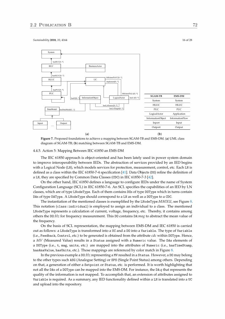
Sustainability 2018, 10, 4164 16 of 28
System
BUC
HLUC
PUC
BusinessActor
LogicalActorInformationObject
UC
OutportInport
DataModel
hasBUC[0..*]
hasHLUC[0..*]
hasPUC[0..*]
IsRelatedToLA[0..*]
hasLATarget[0..*]hasLASource[0..*]
Implement[0..*]
hasIO[0..*]
hasDataModel[1..1]
…
hasLA[0..*]
IsRelatedToUC[0..*]
(a)
SGAM-TB EMS-DM
System System
HLUC HLUC
PUC PUC
LogicalActor Application
InformationObject InformationFlow
Inport Input
Outport Output
(b)Figure 7. Proposed foundations to achieve a mapping between SGAM-TB and EMS-DM. (a) UML classdiagram of SGAM-TB; (b) matching between SGAM-TB and EMS-DM.
4.4.5. Action 5: Mapping Between IEC 61850 an EMS-DM
The IEC 61850 approach is object-oriented and has been lately used in power system domainto improve interoperability between IEDs. The abstraction of services provided by an IED beginswith a Logical Node (LN), which models services for protection, measurement, control, etc. Each LN isdefined as a class within the IEC 61850-7-4 specification [41]. Data Objects (DO) refine the definition ofa LN, they are specified by Common Data Classes (CDC) in IEC 61850-7-3 [42].
On the other hand, IEC 61850 defines a language to configure IEDs under the name of SystemConfiguration Language (SCL) in IEC 61850-7-6. An SCL specifies the capabilities of an IED by LNclasses, which are of type LNodeType. Each of them contains DOs of type DOType which in turns containDAs of type DAType. A LNodeType should correspond to a LN as well as a DOType to a CDC.
The instantiation of the mentioned classes is exemplified by the LNodeType:MMXU, see Figure 8.This notation (class:individual) is employed to assign an individual to a class. The mentionedLNodeType represents a calculation of current, voltage, frequency, etc. Thereby, it contains amongothers the DO:Hz for frequency measurement. This DO contains DA:mag to abstract the mean value ofthe frequency.
On the basis of SCL representation, the mapping between EMS-DM and IEC 61850 is carriedout as follows: a LNodeType is transformed into a UC and a DO into a Variable. The type of Variable(i.e., Feedback, Control, etc.) to be generated is obtained from the attribute cdc within DOType. Hence,a MV (Measured Value) results in a Status assigned with a Numeric value. The DAs elements ofa DOType (i.e., t, mag, units, etc.) are mapped into the attributes of Numeric (i.e., hasTimeStamp,hasAnaValue, hasUnits, etc.). Those mappings are referenced by color match in Figure 8.
In the previous example a DO:Hz representing a MV resulted in a Status. However, a DO may belongto the other types such ASG (Analogue Setting) or SPS (Single Point Status) among others. Dependingon that, a generation of either a Setpoint or Status, etc. is performed. It is worth highlighting thatnot all the DAs of a DOType can be mapped into the EMS-DM. For instance, the DA:q that represents thequality of the information is not mapped. To accomplish that, an extension of attributes assigned toVariable is required. As a summary, any IED functionality defined within a LN is translated into a UCand upload into the repository.
2.2 Publication B 72
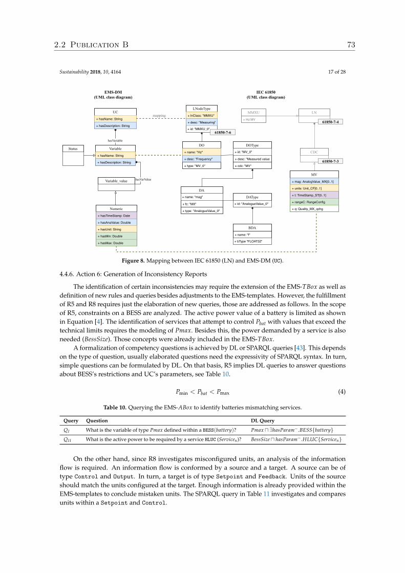
Sustainability 2018, 10, 4164 17 of 28
LNodeType
+ lnClass: "MMXU"
+ desc: "Measuring"
+ id: "MMXU_0"
DOType
+ id: "MV_0"
+ desc: "Measured value"
+ cdc: "MV"
DA
+ name: "mag"
+ fc: "MX"
+ type: "AnalogueValue_0"
DAType
+ id: "AnalogueValue_0"
BDA
+ name: "f"
+ bType "FLOAT32"
IEC 61850 (UML class diagram)
Numeric
+ hasTimeStamp: Date
+ hasAnaValue: Double
+ hasUnit: String
+ hasMin: Double
+ hasMax: Double
hasVarValue
Status
hasVariable
UC
+ hasName: String
+ hasDescription: String
hasVariable[0..*]Variable
+ hasName: String
+ hasDescription: String
EMSDM (UML class diagram)
Variable_value
MV
+ mag: AnalogValue_MX[0..1]
+ units: Unit_CF[0..1]
+ t: TimeStamp_ST[0..1]
+ rangeC: RangeConfig
+ q: Quality_MX_qchg
DO
+ name: "Hz"
+ desc: "Frequency"
+ type: "MV_0"
CDC
mappingLN
6185074
MMXU
+ Hz:MV
6185073
6185076
Figure 8. Mapping between IEC 61850 (LN) and EMS-DM (UC).
4.4.6. Action 6: Generation of Inconsistency Reports
The identification of certain inconsistencies may require the extension of the EMS-TBox as well asdefinition of new rules and queries besides adjustments to the EMS-templates. However, the fulfillmentof R5 and R8 requires just the elaboration of new queries, those are addressed as follows. In the scopeof R5, constraints on a BESS are analyzed. The active power value of a battery is limited as shownin Equation [4]. The identification of services that attempt to control Pbat with values that exceed thetechnical limits requires the modeling of Pmax. Besides this, the power demanded by a service is alsoneeded (BessSize). Those concepts were already included in the EMS-TBox.
A formalization of competency questions is achieved by DL or SPARQL queries [43]. This dependson the type of question, usually elaborated questions need the expressivity of SPARQL syntax. In turn,simple questions can be formulated by DL. On that basis, R5 implies DL queries to answer questionsabout BESS’s restrictions and UC’s parameters, see Table 10.
Pmin < Pbat < Pmax (4)
Table 10. Querying the EMS-ABox to identify batteries mismatching services.
Query Question DL Query
QI What is the variable of type Pmax defined within a BESS(battery)? Pmax u ∃hasParam−.BESS{battery}QI I What is the active power to be required by a service HLUC (Servicen)? BessSize u hasParam−.HLUC{Servicen}
On the other hand, since R8 investigates misconfigured units, an analysis of the informationflow is required. An information flow is conformed by a source and a target. A source can be oftype Control and Output. In turn, a target is of type Setpoint and Feedback. Units of the sourceshould match the units configured at the target. Enough information is already provided within theEMS-templates to conclude mistaken units. The SPARQL query in Table 11 investigates and comparesunits within a Setpoint and Control.
2.2 Publication B 73
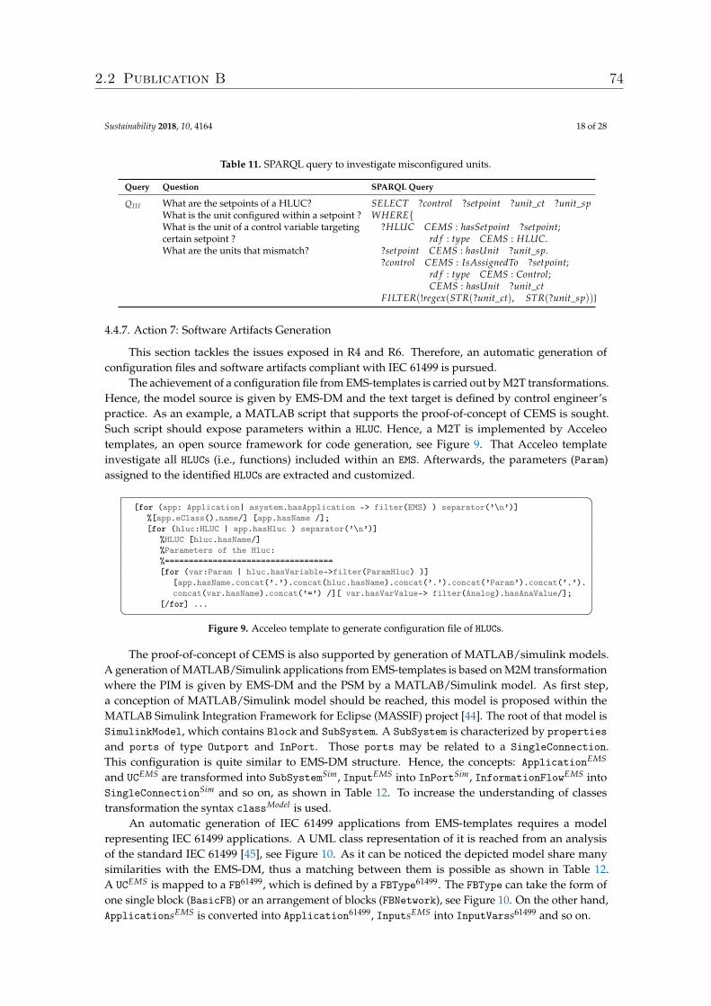
Sustainability 2018, 10, 4164 18 of 28
Table 11. SPARQL query to investigate misconfigured units.
Query Question SPARQL Query
QI I I What are the setpoints of a HLUC?What is the unit configured within a setpoint ?What is the unit of a control variable targetingcertain setpoint ?What are the units that mismatch?
SELECT ?control ?setpoint ?unit_ct ?unit_spWHERE{
?HLUC CEMS : hasSetpoint ?setpoint;rd f : type CEMS : HLUC.
?setpoint CEMS : hasUnit ?unit_sp.?control CEMS : IsAssignedTo ?setpoint;
rd f : type CEMS : Control;CEMS : hasUnit ?unit_ct
FILTER(!regex(STR(?unit_ct), STR(?unit_sp))}
4.4.7. Action 7: Software Artifacts Generation
This section tackles the issues exposed in R4 and R6. Therefore, an automatic generation ofconfiguration files and software artifacts compliant with IEC 61499 is pursued.
The achievement of a configuration file from EMS-templates is carried out by M2T transformations.Hence, the model source is given by EMS-DM and the text target is defined by control engineer’spractice. As an example, a MATLAB script that supports the proof-of-concept of CEMS is sought.Such script should expose parameters within a HLUC. Hence, a M2T is implemented by Acceleotemplates, an open source framework for code generation, see Figure 9. That Acceleo templateinvestigate all HLUCs (i.e., functions) included within an EMS. Afterwards, the parameters (Param)assigned to the identified HLUCs are extracted and customized. �
[for (app: Application| asystem.hasApplication -> filter(EMS) ) separator(’\n’)]%[app.eClass().name/] [app.hasName /];[for (hluc:HLUC | app.hasHluc ) separator(’\n’)]
%HLUC [hluc.hasName/]%Parameters of the Hluc:%===================================[for (var:Param | hluc.hasVariable->filter(ParamHluc) )]
[app.hasName.concat(’.’).concat(hluc.hasName).concat(’.’).concat(’Param’).concat(’.’).concat(var.hasName).concat(’=’) /][ var.hasVarValue-> filter(Analog).hasAnaValue/];
[/for] ...� �Figure 9. Acceleo template to generate configuration file of HLUCs.
The proof-of-concept of CEMS is also supported by generation of MATLAB/simulink models.A generation of MATLAB/Simulink applications from EMS-templates is based on M2M transformationwhere the PIM is given by EMS-DM and the PSM by a MATLAB/Simulink model. As first step,a conception of MATLAB/Simulink model should be reached, this model is proposed within theMATLAB Simulink Integration Framework for Eclipse (MASSIF) project [44]. The root of that model isSimulinkModel, which contains Block and SubSystem. A SubSystem is characterized by propertiesand ports of type Outport and InPort. Those ports may be related to a SingleConnection.This configuration is quite similar to EMS-DM structure. Hence, the concepts: ApplicationEMS
and UCEMS are transformed into SubSystemSim, InputEMS into InPortSim, InformationFlowEMS intoSingleConnectionSim and so on, as shown in Table 12. To increase the understanding of classestransformation the syntax classModel is used.
An automatic generation of IEC 61499 applications from EMS-templates requires a modelrepresenting IEC 61499 applications. A UML class representation of it is reached from an analysisof the standard IEC 61499 [45], see Figure 10. As it can be noticed the depicted model share manysimilarities with the EMS-DM, thus a matching between them is possible as shown in Table 12.A UCEMS is mapped to a FB61499, which is defined by a FBType61499. The FBType can take the form ofone single block (BasicFB) or an arrangement of blocks (FBNetwork), see Figure 10. On the other hand,ApplicationsEMS is converted into Application61499, InputsEMS into InputVarss61499 and so on.
2.2 Publication B 74
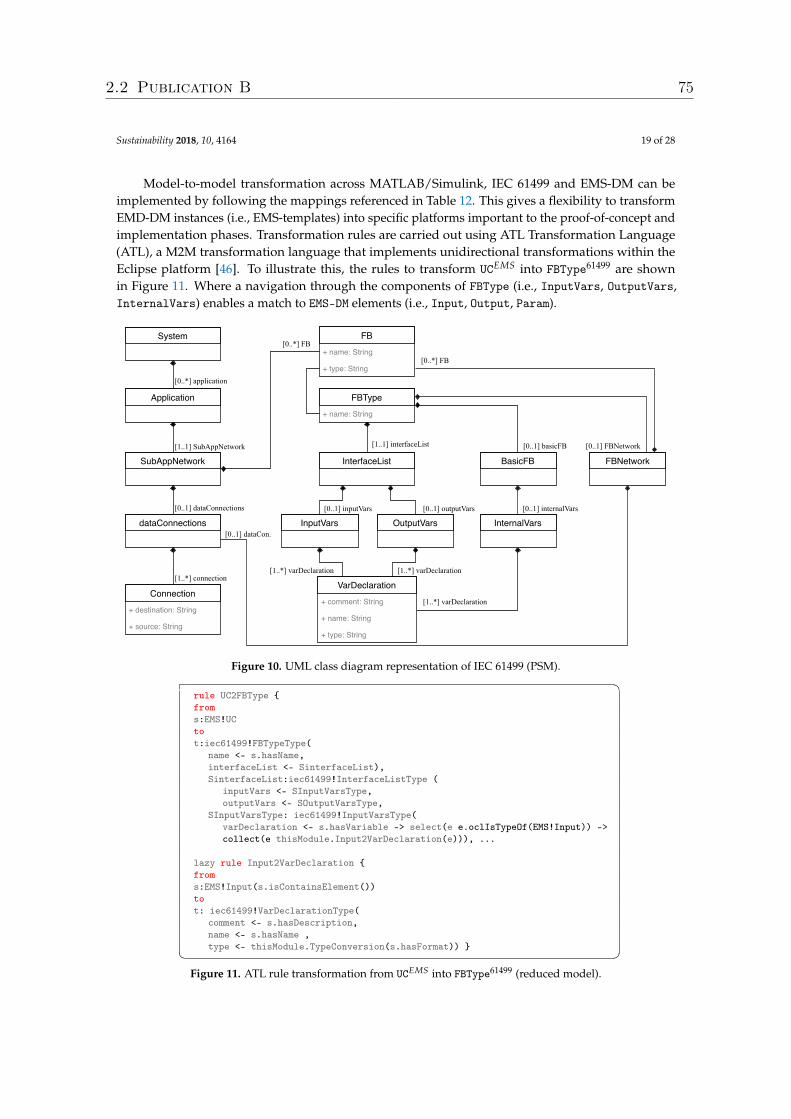
Sustainability 2018, 10, 4164 19 of 28
Model-to-model transformation across MATLAB/Simulink, IEC 61499 and EMS-DM can beimplemented by following the mappings referenced in Table 12. This gives a flexibility to transformEMD-DM instances (i.e., EMS-templates) into specific platforms important to the proof-of-concept andimplementation phases. Transformation rules are carried out using ATL Transformation Language(ATL), a M2M transformation language that implements unidirectional transformations within theEclipse platform [46]. To illustrate this, the rules to transform UCEMS into FBType61499 are shownin Figure 11. Where a navigation through the components of FBType (i.e., InputVars, OutputVars,InternalVars) enables a match to EMS-DM elements (i.e., Input, Output, Param).
System
Application
SubAppNetwork
dataConnections
Connection+ destination: String
+ source: String
FBType+ name: String
InterfaceList BasicFB
InputVars OutputVars
VarDeclaration+ comment: String
+ name: String
+ type: String
InternalVars
FB+ name: String
+ type: String
FBNetwork
[0..*] application
[1..1] SubAppNetwork
[0..1] dataConnections
[1..*] connection
[0..*] FB
[0..1] basicFB[1..1] interfaceList
[0..1] inputVars [0..1] outputVars [0..1] internalVars
[1..*] varDeclaration
[1..*] varDeclaration[1..*] varDeclaration
[0..*] FB
[0..1] dataCon.
[0..1] FBNetwork
Figure 10. UML class diagram representation of IEC 61499 (PSM). �rule UC2FBType {froms:EMS!UCtot:iec61499!FBTypeType(
name <- s.hasName,interfaceList <- SinterfaceList),SinterfaceList:iec61499!InterfaceListType (
inputVars <- SInputVarsType,outputVars <- SOutputVarsType,
SInputVarsType: iec61499!InputVarsType(varDeclaration <- s.hasVariable -> select(e e.oclIsTypeOf(EMS!Input)) ->collect(e thisModule.Input2VarDeclaration(e))), ...
lazy rule Input2VarDeclaration {froms:EMS!Input(s.isContainsElement())tot: iec61499!VarDeclarationType(
comment <- s.hasDescription,name <- s.hasName ,type <- thisModule.TypeConversion(s.hasFormat)) }� �
Figure 11. ATL rule transformation from UCEMS into FBType61499 (reduced model).
2.2 Publication B 75
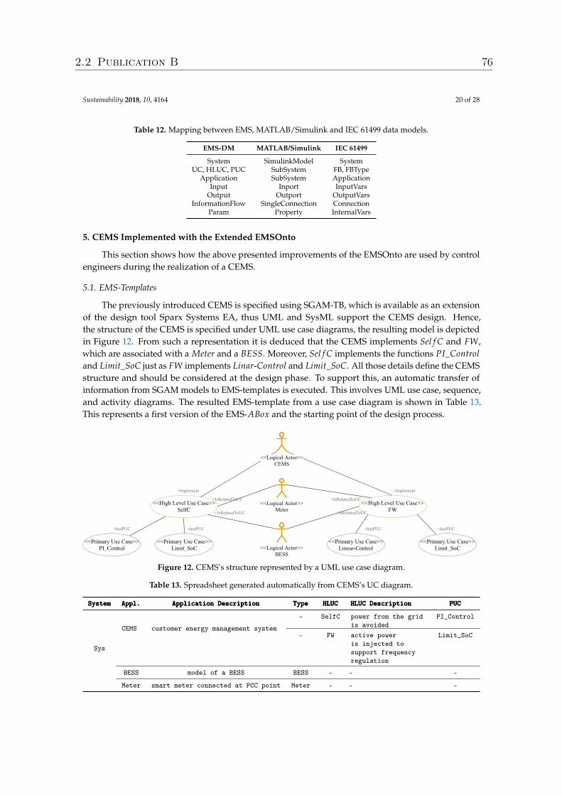
Sustainability 2018, 10, 4164 20 of 28
Table 12. Mapping between EMS, MATLAB/Simulink and IEC 61499 data models.
EMS-DM MATLAB/Simulink IEC 61499
System SimulinkModel SystemUC, HLUC, PUC SubSystem FB, FBType
Application SubSystem ApplicationInput Inport InputVars
Output Outport OutputVarsInformationFlow SingleConnection Connection
Param Property InternalVars
5. CEMS Implemented with the Extended EMSOnto
This section shows how the above presented improvements of the EMSOnto are used by controlengineers during the realization of a CEMS.
5.1. EMS-Templates
The previously introduced CEMS is specified using SGAM-TB, which is available as an extensionof the design tool Sparx Systems EA, thus UML and SysML support the CEMS design. Hence,the structure of the CEMS is specified under UML use case diagrams, the resulting model is depictedin Figure 12. From such a representation it is deduced that the CEMS implements Sel f C and FW,which are associated with a Meter and a BESS. Moreover, Sel f C implements the functions PI_Controland Limit_SoC just as FW implements Linar-Control and Limit_SoC. All those details define the CEMSstructure and should be considered at the design phase. To support this, an automatic transfer ofinformation from SGAM models to EMS-templates is executed. This involves UML use case, sequence,and activity diagrams. The resulted EMS-template from a use case diagram is shown in Table 13.This represents a first version of the EMS-ABox and the starting point of the design process.
<<High Level Use Case>> SelfC
<<Primary Use Case>> PI_Control
<<Primary Use Case>> Limit_SoC
<<Logical Actor>> Meter
<<Logical Actor>> CEMS
<<Logical Actor>> BESS
+hasPUC +hasPUC +hasPUC
+Implement
+IsRelatedToUC
+IsRelatedToUC<<High Level Use Case>>
FW
<<Primary Use Case>> LinearControl
+Implement
<<Primary Use Case>> Limit_SoC
+hasPUC
+IsRelatedToUC
+IsRelatedToUC
Figure 12. CEMS’s structure represented by a UML use case diagram.
Table 13. Spreadsheet generated automatically from CEMS’s UC diagram.
SystemSystemSystem Appl.Appl.Appl. Application DescriptionApplication DescriptionApplication Description TypeTypeType HLUCHLUCHLUC HLUC DescriptionHLUC DescriptionHLUC Description PUCPUCPUC
Sys
CEMS customer energy management system
- SelfC power from the gridis avoided
PI_Control
- FW active poweris injected tosupport frequencyregulation
Limit_SoC
BESS model of a BESS BESS - - -
Meter smart meter connected at PCC point Meter - - -
2.2 Publication B 76
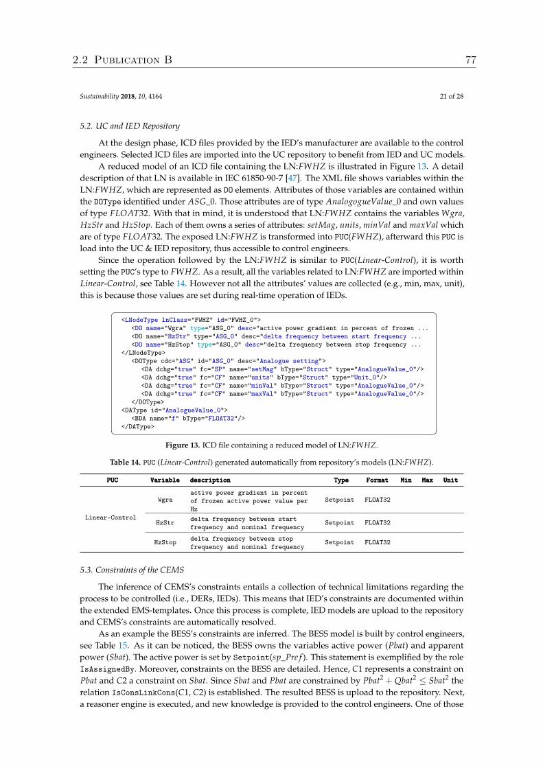
Sustainability 2018, 10, 4164 21 of 28
5.2. UC and IED Repository
At the design phase, ICD files provided by the IED’s manufacturer are available to the controlengineers. Selected ICD files are imported into the UC repository to benefit from IED and UC models.
A reduced model of an ICD file containing the LN:FWHZ is illustrated in Figure 13. A detaildescription of that LN is available in IEC 61850-90-7 [47]. The XML file shows variables within theLN:FWHZ, which are represented as DO elements. Attributes of those variables are contained withinthe DOType identified under ASG_0. Those attributes are of type AnalogogueValue_0 and own valuesof type FLOAT32. With that in mind, it is understood that LN:FWHZ contains the variables Wgra,HzStr and HzStop. Each of them owns a series of attributes: setMag, units, minVal and maxVal whichare of type FLOAT32. The exposed LN:FWHZ is transformed into PUC(FWHZ), afterward this PUC isload into the UC & IED repository, thus accessible to control engineers.
Since the operation followed by the LN:FWHZ is similar to PUC(Linear-Control), it is worthsetting the PUC’s type to FWHZ. As a result, all the variables related to LN:FWHZ are imported withinLinear-Control, see Table 14. However not all the attributes’ values are collected (e.g., min, max, unit),this is because those values are set during real-time operation of IEDs.� �
<LNodeType lnClass="FWHZ" id="FWHZ_0"><DO name="Wgra" type="ASG_0" desc="active power gradient in percent of frozen ...<DO name="HzStr" type="ASG_0" desc="delta frequency between start frequency ...<DO name="HzStop" type="ASG_0" desc="delta frequency between stop frequency ...
</LNodeType><DOType cdc="ASG" id="ASG_0" desc="Analogue setting">
<DA dchg="true" fc="SP" name="setMag" bType="Struct" type="AnalogueValue_0"/><DA dchg="true" fc="CF" name="units" bType="Struct" type="Unit_0"/><DA dchg="true" fc="CF" name="minVal" bType="Struct" type="AnalogueValue_0"/><DA dchg="true" fc="CF" name="maxVal" bType="Struct" type="AnalogueValue_0"/>
</DOType><DAType id="AnalogueValue_0">
<BDA name="f" bType="FLOAT32"/></DAType>� �
Figure 13. ICD file containing a reduced model of LN:FWHZ.
Table 14. PUC (Linear-Control) generated automatically from repository’s models (LN:FWHZ).
PUCPUCPUC VariableVariableVariable descriptiondescriptiondescription TypeTypeType FormatFormatFormat MinMinMin MaxMaxMax UnitUnitUnit
Linear-Control
Wgraactive power gradient in percentof frozen active power value perHz
Setpoint FLOAT32
HzStr delta frequency between startfrequency and nominal frequency
Setpoint FLOAT32
HzStop delta frequency between stopfrequency and nominal frequency
Setpoint FLOAT32
5.3. Constraints of the CEMS
The inference of CEMS’s constraints entails a collection of technical limitations regarding theprocess to be controlled (i.e., DERs, IEDs). This means that IED’s constraints are documented withinthe extended EMS-templates. Once this process is complete, IED models are upload to the repositoryand CEMS’s constraints are automatically resolved.
As an example the BESS’s constraints are inferred. The BESS model is built by control engineers,see Table 15. As it can be noticed, the BESS owns the variables active power (Pbat) and apparentpower (Sbat). The active power is set by Setpoint(sp_Pre f ). This statement is exemplified by the roleIsAssignedBy. Moreover, constraints on the BESS are detailed. Hence, C1 represents a constraint onPbat and C2 a constraint on Sbat. Since Sbat and Pbat are constrained by Pbat2 + Qbat2 ≤ Sbat2 therelation IsConsLinkCons(C1, C2) is established. The resulted BESS is upload to the repository. Next,a reasoner engine is executed, and new knowledge is provided to the control engineers. One of those
2.2 Publication B 77
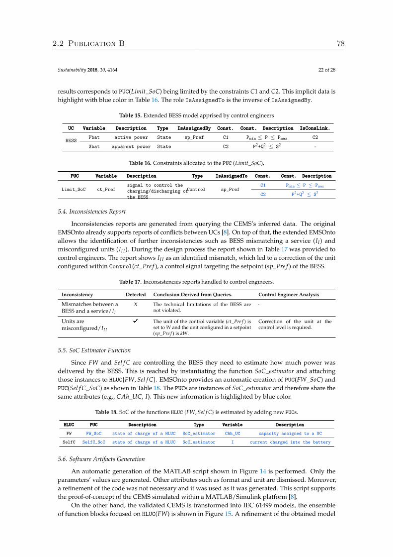
Sustainability 2018, 10, 4164 22 of 28
results corresponds to PUC(Limit_SoC) being limited by the constraints C1 and C2. This implicit data ishighlight with blue color in Table 16. The role IsAssignedTo is the inverse of IsAssignedBy.
Table 15. Extended BESS model apprised by control engineers
UCUCUC VariableVariableVariable DescriptionDescriptionDescription TypeTypeType IsAssignedByIsAssignedByIsAssignedBy Const.Const.Const. Const. DescriptionConst. DescriptionConst. Description IsConsLink.IsConsLink.IsConsLink.
BESSPbat active power State sp_Pref C1 Pmin ≤ P ≤ Pmax C2
Sbat apparent power State C2 P2+Q2 ≤ S2 -
Table 16. Constraints allocated to the PUC (Limit_SoC).
PUCPUCPUC VariableVariableVariable DescriptionDescriptionDescription TypeTypeType IsAssignedToIsAssignedToIsAssignedTo Const.Const.Const. Const. DescriptionConst. DescriptionConst. Description
Limit_SoC ct_Prefsignal to control thecharging/discharging ofthe BESS
Control sp_PrefC1 Pmin ≤ P ≤ Pmax
C2 P2+Q2 ≤ S2
5.4. Inconsistencies Report
Inconsistencies reports are generated from querying the CEMS’s inferred data. The originalEMSOnto already supports reports of conflicts between UCs [8]. On top of that, the extended EMSOntoallows the identification of further inconsistencies such as BESS mismatching a service (II) andmisconfigured units (II I). During the design process the report shown in Table 17 was provided tocontrol engineers. The report shows II I as an identified mismatch, which led to a correction of the unitconfigured within Control(ct_Pre f ), a control signal targeting the setpoint (sp_Pre f ) of the BESS.
Table 17. Inconsistencies reports handled to control engineers.
Inconsistency Detected Conclusion Derived from Queries. Control Engineer Analysis
Mismatches between aBESS and a service/II
X The technical limitations of the BESS arenot violated.
-
Units aremisconfigured/II I
D The unit of the control variable (ct_Pre f ) isset to W and the unit configured in a setpoint(sp_Pre f ) is kW.
Correction of the unit at thecontrol level is required.
5.5. SoC Estimator Function
Since FW and Sel f C are controlling the BESS they need to estimate how much power wasdelivered by the BESS. This is reached by instantiating the function SoC_estimator and attachingthose instances to HLUC{FW, Sel f C}. EMSOnto provides an automatic creation of PUC(FW_SoC) andPUC(Sel f C_SoC) as shown in Table 18. The PUCs are instances of SoC_estimator and therefore share thesame attributes (e.g., CAh_UC, I). This new information is highlighted by blue color.
Table 18. SoC of the functions HLUC {FW, Sel f C} is estimated by adding new PUCs.
HLUCHLUCHLUC PUCPUCPUC DescriptionDescriptionDescription TypeTypeType VariableVariableVariable DescriptionDescriptionDescription
FW FW_SoC state of charge of a HLUC SoC_estimator CAh_UC capacity assigned to a UC
SelfC SelfC_SoC state of charge of a HLUC SoC_estimator I current charged into the battery
5.6. Software Artifacts Generation
An automatic generation of the MATLAB script shown in Figure 14 is performed. Only theparameters’ values are generated. Other attributes such as format and unit are dismissed. Moreover,a refinement of the code was not necessary and it was used as it was generated. This script supportsthe proof-of-concept of the CEMS simulated within a MATLAB/Simulink platform [8].
On the other hand, the validated CEMS is transformed into IEC 61499 models, the ensembleof function blocks focused on HLUC(FW) is shown in Figure 15. A refinement of the obtained model
2.2 Publication B 78
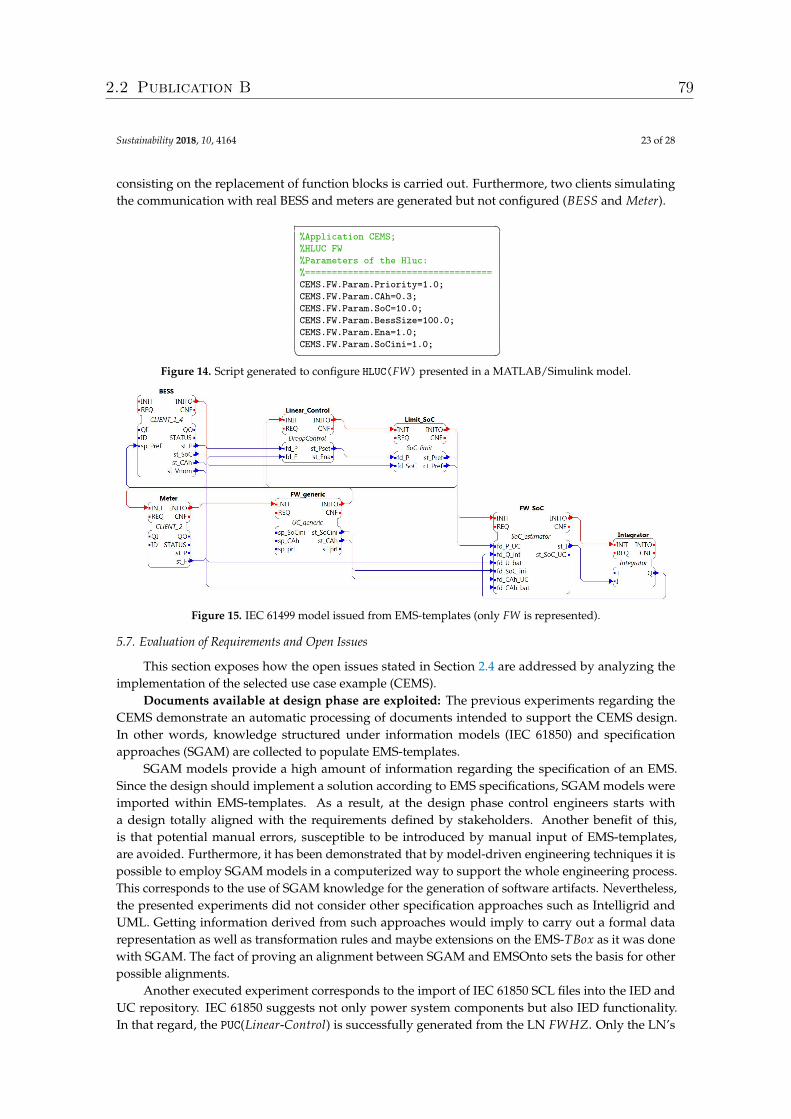
Sustainability 2018, 10, 4164 23 of 28
consisting on the replacement of function blocks is carried out. Furthermore, two clients simulatingthe communication with real BESS and meters are generated but not configured (BESS and Meter).�
%Application CEMS;%HLUC FW%Parameters of the Hluc:%===================================CEMS.FW.Param.Priority=1.0;CEMS.FW.Param.CAh=0.3;CEMS.FW.Param.SoC=10.0;CEMS.FW.Param.BessSize=100.0;CEMS.FW.Param.Ena=1.0;CEMS.FW.Param.SoCini=1.0;� �
Figure 14. Script generated to configure HLUC(FW) presented in a MATLAB/Simulink model.
Figure 15. IEC 61499 model issued from EMS-templates (only FW is represented).
5.7. Evaluation of Requirements and Open Issues
This section exposes how the open issues stated in Section 2.4 are addressed by analyzing theimplementation of the selected use case example (CEMS).
Documents available at design phase are exploited: The previous experiments regarding theCEMS demonstrate an automatic processing of documents intended to support the CEMS design.In other words, knowledge structured under information models (IEC 61850) and specificationapproaches (SGAM) are collected to populate EMS-templates.
SGAM models provide a high amount of information regarding the specification of an EMS.Since the design should implement a solution according to EMS specifications, SGAM models wereimported within EMS-templates. As a result, at the design phase control engineers starts witha design totally aligned with the requirements defined by stakeholders. Another benefit of this,is that potential manual errors, susceptible to be introduced by manual input of EMS-templates,are avoided. Furthermore, it has been demonstrated that by model-driven engineering techniques it ispossible to employ SGAM models in a computerized way to support the whole engineering process.This corresponds to the use of SGAM knowledge for the generation of software artifacts. Nevertheless,the presented experiments did not consider other specification approaches such as Intelligrid andUML. Getting information derived from such approaches would imply to carry out a formal datarepresentation as well as transformation rules and maybe extensions on the EMS-TBox as it was donewith SGAM. The fact of proving an alignment between SGAM and EMSOnto sets the basis for otherpossible alignments.
Another executed experiment corresponds to the import of IEC 61850 SCL files into the IED andUC repository. IEC 61850 suggests not only power system components but also IED functionality.In that regard, the PUC(Linear-Control) is successfully generated from the LN FWHZ. Only the LN’s
2.2 Publication B 79
Sustainability 2018, 10, 4164 24 of 28
attributes required by engineers were covered in the experiments. However, since the EMS-TBox doesnot contain all the classes and attributes defined within IEC 61850 a full import of the LN’s attributeswould involve a further extension of the EMS-TBox.
The successful import of SCL files attempts to demonstrate that power utility information modelscan be used to feed the UC and IED repository. This means that the same mechanisms used toimport IEC 61850 models are expected for other models such as energy market communication modelsformalized in IEC 62325 and also smart meter models defined within IEC 62056 among others [48].
Enlargement of inferred knowledge: Inferences provided by EMSOnto were extended.The inferences performed in this work support control engineers by deducing the constraints tobe respected. Besides this, the identification of inconsistencies that may harm the correct operation ofcontrol applications was carried out. On top of that, new functions (SoC_Estimator) were created toaccelerate and support the design of control applications.
Since different sort of inferences were achieved this may lead to think that EMSOnto is flexible toimplement any kind of inference. However, this strictly depends on the expressivity provided by theontology (SROIQ(D)) and also the rules. Although SROIQ(D) is well defined, the expressivityfor rules is determined by rule languages. In this work, SWRL and SPARQL were enough toaddress the control engineer’s requirements. Nevertheless, other requirements may need to usethe Rule Interchange Format (RIF), which provides the means to insert primary logic programminglanguages [37], or even to extend ontologies with probabilistic inference and temporal logic [49].
Flexible generation of software artifacts: CEMS experiments demonstrate that generatedcode and models support control engineers not only in the proof-of-concept but also duringthe implementation phase. To make this possible, mappings between a power system emulator(MATLAB/Simulink), a controller platform (IEC 61499 platform) and Emsonto are conceived as wellas text templates for code generation (MATLAB script). This evaluation lays the groundwork forimplementations to other specific platforms (IEC 61131-3, PowerFactory).
The final realization of control applications requires the participation of engineers for thecustomization of generated models as well as the definition of the control algorithm’s behavior.In the use case example, communication interfaces were generated (BESS and Meter clients), althoughnot configured. Consequently, the generation of a full control application ready to be tested is not fullyautomated. Indeed, other approaches cover those gaps. For instance, PSAL supports the design andimplementation of communication and component layers [10]. Therefore, the cooperation betweendifferent engineering and development approaches is encouraged.
6. Conclusions
In the near future, a high integration of BESS within the distribution grid may very well becomea reality since they can provide a broad range of services. Those services are likely to be deployedwithin an EMS which in turn will control the active and reactive power of a BESS. In that context,this work seeks an automated and adaptable approach that would support the engineering process ofsuch EMS. Therefore, available engineering approaches are studied to realize what are the open issuesto be addressed. Among the studied approaches, EMSOnto—a holistic approach for multi-functionalBESS—is selected as the reference methodology.
The identified open issues are handled by the EMSOnto expert, whose main role is thecustomization of the EMSOnto according to control engineer’s requirements. As a solution, the expertproposes a set of actions based on model-driven engineering techniques and ontologies. Those aresummarized as the extension of the EMS-TBox, setting up of new rules and queries, extension ofEMS-templates, and finally the conception of data models and transformation rules. All those actionsare exemplified by a selected use case example showing the realization of a CEMS, which encapsulatesa series of control engineering requirements. The realization of the CEMS allows to evaluate theefficacy and limitations of the proposed solutions. The experiments were tied to specific toolsand standards (MATLAB/Simulink, IEC 61850, IEC 61499, SGAM) to show the EMSOnto expert’s
2.2 Publication B 80
Sustainability 2018, 10, 4164 25 of 28
actions. These experiments set foundations for further customizations of EMSOnto with the aim ofencompassing other standards and tools. An analysis of the tasks performed by the EMSOnto expert,after collecting and understanding the control engineer’s requirements, is outlined, and discussed:
1. Define an ontology/data model of the EMS under study2. Integrate rules and queries to the ontology3. Propose a methodology to gather knowledge from the EMS4. Design data models for specific software platforms, IEDs, DERs, etc.5. Elaborate transformation rules for code/text and model generation
From the abovementioned steps, only steps 4 and 5 should be carried out to exploit informationsources available at the specification stage. This is demonstrated by the CEMS example, whereEMS-templates are fed with SGAM models. Hence, a consistency between specification and designphases was reached. Similarly, the abovementioned steps can also be applied to other specificationand design approaches such as IntelliGrid, PSAL, etc. On the other hand, by following steps 1, 2 and3 the inference of implicit knowledge is achieved. It was demonstrated by detecting inconsistencieswithin multi-functional BESS (e.g., misconfigured units) and by deducing functions at the designtime (e.g., SoC_estimator). The proposed methodology can enable inference within other modernapproaches (e.g., PSAL) as well. Besides this, a customized generation of software artifacts is achievedby performing steps 1, 4 and 5. As a result, EMSOnto is now able to support the implementation stagewith generated code aligned to a controller platform (IEC 61499). In the same way, other approachescan also benefit from the referred steps to achieve compatibility with different specific platforms.
From the CEMS use case example, it is worth noticing that limitations of inferences dependon the expressivity of the ontology (e.g., OWL ontology) and the intelligence provided by rulelanguages. Consequently, it is encouraged to choose the right ontology language for the handlingof the knowledge to be inferred. Moreover, the validation of EMS involves a dynamic process.Therefore, the identification of certain inconsistencies at that stage would require the time notion,which in a future work can be achieved by extending the expressiveness provided by ontologies withtemporal logic [50]. On the other hand, with the current approaches, it is common to document theplanned design (e.g., PSAL, SGAM, EMSOnto). Modifications to the stipulated design occurs oftenduring proof-of-concept and implementations stages. However, since the modified information is nottracked then the generated software artifacts would not be aligned with the final validated design.To handle that issue, reverse engineering along the engineering process is encouraged [51]. Moreover,the validation of multi-functional BESS applications often involves tools such as communicationnetworks and co-simulation frameworks. This means that the communication and component domainsshould be considered by the selected approach. However, this is not always the case since thementioned domains are not modeled within EMSOnto. Thereby, as future work it is encouraged tocombine different approaches, for instance, combining EMSOnto with PSAL where a formal semanticfor communication interfaces and components is addressed.
Author Contributions: C.Z. wrote the paper and carried out the conceptualization, investigation and validationof the work. F.P.A. and T.I.S. participated in the conceptualization of the proposed approach and reviewed thefinal manuscript. T.I.S. supervised the overall work.
Funding: This work is partly supported by the Austrian Ministry for Transport, Innovation and Technology(bmvit) and the Austrian Research Promotion Agency (FFG) under the ICT of the Future Programme in the MESSEproject (FFG No. 861265).
Conflicts of Interest: The authors declare no conflict of interest.
2.2 Publication B 81
Sustainability 2018, 10, 4164 26 of 28
References
1. Alizadeh, M.; Parsa Moghaddam, M.; Amjady, N.; Siano, P.; Sheikh-El-Eslami, M. Flexibility in Future PowerSystems with High Renewable Penetration: A Review. Renew. Sustain. Energy Rev. 2016, 57, 1186–1193.[CrossRef]
2. Koller, M.; Borsche, T.; Ulbig, A.; Andersson, G. Review of Grid Applications with the Zurich 1MW BatteryEnergy Storage System. Electr. Power Syst. Res. 2015, 120, 128–135. [CrossRef]
3. EERA Joint Programme on Smart Grids-Sub-Programme 4-Electrical Energy Technologies; Technical Report D4.3Integration of Storage Resources to Smart Grids: Possible Services, D4.4 Control Algorithms for StorageApplications in Smart Grid; EERA: Brussels, Belgium, 2014.
4. Zanabria, C.; Pröstl Andrén, F.; Strasser, T.I. Comparing Specification and Design Approaches for PowerSystems Applications. In Proceedings of the 2018 IEEE PES Transmission and Distribution Conference andExhibition—Latin America, Lima, Peru, 18–21 September 2018; p. 5.
5. Santodomingo, R.; Uslar, M.; Goring, A.; Gottschalk, M.; Nordstrom, L.; Saleem, A.; Chenine, M.SGAM-Based Methodology to Analyse Smart Grid Solutions in DISCERN European Research Project.In Proceedings of the 2014 IEEE International Energy Conference (ENERGYCON), Dubrovnik, Croatia,13–16 May 2014; pp. 751–758. [CrossRef]
6. Working Group Sustainable Processes (SG-CG/SP). CEN-CENELEC-ETSI Smart Grid CoordinationGroupSustainableProcesses; Technical Report; CEN-CENELEC-ETSI: Brussels, Belgium, 2012.
7. International Electrotechnical Commission (IEC). IEC 62559-2 Use Case Methodology-Part2: Definition of theTemplates for Use Cases, Actor List and Requirement List; IEC: Geneva, Switzerland, 2015.
8. Zanabria, C.; Pröstl Andrén, F.; Kathan, J.; Strasser, T.I. Rapid Prototyping of Multi-Functional BatteryEnergy Storage System Applications. Appl. Sci. 2018, 8, 1326. [CrossRef]
9. Zanabria, C.; Pröstl Andrén, F.; Kathan, J.; Strasser, T. Approach for Handling Controller Conflicts withinMulti-Functional Energy Storage Systems. In Proceedings of the CIRED-Open Access Proceedings Journal,Glasgow, UK, 12–15 June 2017; pp. 1575–1578.
10. Andrén, F.P.; Strasser, T.I.; Kastner, W. Engineering Smart Grids: Applying Model-Driven Developmentfrom Use Case Design to Deployment. Energies 2017, 10, 374. [CrossRef]
11. Tayyebi, A.; Bletterie, B.; Kupzog, F. Primary Control Reserve and Self-Sufficiency Provision withCentral Battery Energy Storage Systens. In Proceedings of the NEIS Conference, Hamburg, Germany,21–22 September 2017; pp. 21–22.
12. Riffonneau, Y.; Bacha, S.; Barruel, F.; Ploix, S. Optimal Power Flow Management for Grid Connected PVSystems with Batteries. IEEE Trans. Sustain. Energy 2011, 2, 309–320. [CrossRef]
13. Boehm, B.; Turner, R. Balancing Agility and Discipline: A Guide for the Perplexed, Portable Documents;Addison-Wesley Professional: Boston, MA, USA, 2003.
14. Andrén, F.; Lehfuss, F.; Strasser, T. A Development and Validation Environment for Real-TimeController-Hardware-in-the-Loop Experiments in Smart Grids. Int. J. Distrib. Energy Resour. Smart Grids2013, 9, 27–50.
15. Gottschalk, M.; Uslar, M.; Delfs, C. The Use Case and Smart Grid Architecture Model Approach: The IEC 62559-2Use Case Template and the SGAM Applied in Various Domains; Springer: New York, NY, USA, 2017.
16. Weilkiens, T. Systems Engineering with SysML/UML: Modeling, Analysis, Design; Elsevier: Amsterdam,The Netherlands, 2011.
17. Tornelli, C.; Radaelli, L.; Rikos, E.; Uslar, M. WP 4 Fully Interoperable Systems Deliverable R4.1: Description of theMethodology for the Detailed Functional Specification of the ELECTRA Solutions; Technical Report; ELECTRA IRP;2015. Available online: http://www.electrairp.eu/index.php?option=com_attachments&task=download&id=441 (accessed on 12 March 2017).
18. Dänekas, C.; Neureiter, C.; Rohjans, S.; Uslar, M.; Engel, D. Towards a Model-Driven-Architecture Processfor Smart Grid Projects. In Digital Enterprise Design & Management; Springer: New York, NY, USA, 2014;pp. 47–58.
19. Higgins, N.; Vyatkin, V.; Nair, N.K.C.; Schwarz, K. Distributed Power System Automation With IEC 61850,IEC 61499, and Intelligent Control. IEEE Trans. Syst. Man Cybern. Part C 2011, 41, 81–92. [CrossRef]
20. Zhabelova, G.; Vyatkin, V.; Dubinin, V. Towards Industrially Usable Agent Technology for Smart GridAutomation. IEEE Trans. Ind. Electron. 2014, 62, 2629–2641. [CrossRef]
2.2 Publication B 82
Sustainability 2018, 10, 4164 27 of 28
21. Schütte, S.; Scherfke, S.; Sonnenschein, M. MOSAIK—Smart Grid simulation API—Toward a Semantic BasedStandard for Interchanging Smart Grid Simulations. In Proceedings of the 1st International Conference onSmart Grids and Green IT Systems, Porto, Portugal, 21 April 2012; SciTePress—Science and TechnologyPublications: Porto, Portugal, 2012; pp. 14–24. [CrossRef]
22. Bhor, D.; Angappan, K.; Sivalingam, K.M. Network and Power-Grid Co-Simulation Framework for SmartGrid Wide-Area Monitoring Networks. J. Netw. Comput. Appl. 2016, 59, 274–284. [CrossRef]
23. Kroetzsch, M.; Simancik, F.; Horrocks, I. A Description Logic Primer. arXiv 2013, arXiv:1201.4089.24. Brambilla, M.; Cabot, J.; Wimmer, M. Model-Driven Software Engineering in Practice. Synth. Lect. Softw. Eng.
2012, 1, 1–182. [CrossRef]25. Andrén, F.; Strasser, T.; Kastner, W. Model-Driven Engineering Applied to Smart Grid Automation Using
IEC 61850 and IEC 61499. In Proceedings of the Power Systems Computation Conference, Wroclaw, Poland,18–22 August 2014; pp. 1–7.
26. Zanabria, C.; Pröstl Andrén, F.; Kathan, J.; Strasser, T. Towards an Integrated Development of ControlApplications for Multi-Functional Energy Storages. In Proceeding of the IEEE 21st International Conferenceon Emerging Technologies and Factory Automation (ETFA), Berlin, Germany, 6–9 September 2016; pp. 1–4.
27. Morales-Trujillo, M.E.; Oktaba, H.; Piattini, M. The making of an OMG standard. Comput. Stand. Interfaces2015, 42, 84–94. [CrossRef]
28. Horrocks, I.; Kutz, O.; Sattler, U. The Even More Irresistible SROIQ. Kr 2006, 6, 57–67.29. Brockmans, S.; Volz, R.; Eberhart, A.; Löffler, P. Visual modeling of OWL DL ontologies using UML.
In Proceeding of the International Semantic Web Conference, Hiroshima, Japan, 7–11 November 2004;Springer: Berlin/Heidelberg, Germany, 2004; pp. 198–213.
30. Andren, F.; Brundlinger, R.; Strasser, T. IEC 61850/61499 Control of Distributed Energy Resources: Concept,Guidelines, and Implementation. IEEE Trans. Energy Convers. 2014, 29, 1008–1017. [CrossRef]
31. Franke, R.; Wiesmann, H. Flexible Modeling of Electrical Power Systems—The Modelica PowerSystemsLibrary. In Proceedings of the 10th International Modelica Conference, Lund, Sweden, 10–12 March 2014;pp. 515–522. [CrossRef]
32. Buscher, M.; Kube, M.; Piech, K.; Lehnhoff, S.; Rohjans, S.; Fischer, L. Towards Smart Grid-Ready Substations:A Standard-Compliant Protection System. In Proceeding of the 2016 Power Systems Computation Conference(PSCC), Genoa, Italy, 20–24 June 2016; pp. 1–6. [CrossRef]
33. Fiaschetti, L.; Antunez, M.; Trapani, E.; Valenzuela, L.; Rubiales, A.; Risso, M.; Boroni, G. Monitoring andControlling Energy Distribution: Implementation of a Distribution Management System Based on CommonInformation Model. Int. J. Electr. Power Energy Syst. 2018, 94, 67–76. [CrossRef]
34. Divya, K.; Østergaard, J. Battery Energy Storage Technology for Power Systems—An Overview. Electr. PowerSyst. Res. 2009, 79, 511–520. [CrossRef]
35. Braam, F.; Diazgranados, L.M.; Hollinger, R.; Engel, B.; Bopp, G.; Erge, T. Distributed Solar Battery SystemsProviding Primary Control Reserve. IET Renew. Power Gen. 2016, 10, 63–70. [CrossRef]
36. Slimani, T. Ontology Development: A Comparing Study on Tools, Languages and Formalisms. Indian J.Sci. Technol. 2015, 8. [CrossRef]
37. Hitzler, P.; Krotzsch, M.; Rudolph, S. Foundations of Semantic Web Technologies; CRC Press: Boca Raton, FL,USA, 2009.
38. Neureiter, C.; Uslar, M.; Engel, D.; Lastro, G. A Standards-Based Approach for Domain Specific Modelling ofSmart Grid System Architectures. In Proceeding of the 2016 11th System of Systems Engineering Conference(SoSE), Kongsberg, Norway, 12–16 June 2016; pp. 1–6. [CrossRef]
39. Horrocks, I.; Patel-Schneider, P.F.; Boley, H.; Tabet, S.; Grosof, B. SWRL: A Semantic Web Rule LanguageCombining OWL and RuleML. W3C Member Submission, 21 May 2004; p. 79.
40. Paul, G.; Alexandre, P.; Axel, P. SPARQL 1.1 Update; W3C: Cambridge, MA, USA, 2013; Volume 21.41. IEC. Communication Networks and Systems for Power Utility Automation. Part 7-4: Basic Communication
Structure—Compatible Logical Node Classes and Data Object Classes; IEC: Geneva, Switzerland, 2010.42. IEC. Communication Networks and Systems for Power Utility Automation. Part 7-3: Basic Communication
Structure-Common Data Classes; IEC: Geneva, Switzerland, 2011.43. Gearon, P.; Passant, A.; Polleres, A. SPARQL 1.1 Query Language; W3C Recommendation; W3C:
Cambridge, MA, USA, 2013; Volume 21.
2.2 Publication B 83
Sustainability 2018, 10, 4164 28 of 28
44. Massif: MATLAB Simulink Integration Framework for Eclipse. 2016. Available online: https://github.com/viatra/massif (accessed on 12 March 2017).
45. International Electrotechnical Commission. IEC 61499-1/Ed.2: Function Blocks—Part 1: Architecture; Standard;IEC: Geneva, Switzerland, 2012.
46. van Amstel, M.; Bosems, S.; Kurtev, I.; Ferreira Pires, L. Performance in Model Transformations: Experimentswith ATL and QVT. In Theory and Practice of Model Transformations; Lecture Notes in Computer Science;Springer: Berlin/Heidelberg, Germany; Zurich, Switzerland, 2011; pp. 198–212.
47. International Electrotechnical Commission (IEC). IEC/TR 61850-90-7—Communication Networks and Systemsfor Power Utility Automation—Part 90-7: Object Models for Power Converters in Distributed Energy Resources(DER) Systems; IEC: Geneva, Switzerland, 2013.
48. Uslar, M.; Specht, M.; Dänekas, C.; Trefke, J.; Rohjans, S.; González, J.M.; Rosinger, C.; Bleiker, R.Standardization in Smart Grids; Power Systems; Springer: Berlin/Heidelberg, Germany, 2013.
49. Gayathri, K.; Easwarakumar, K.; Elias, S. Probabilistic Ontology Based Activity Recognition in Smart HomesUsing Markov Logic Network. Knowl. Based Syst. 2017, 121, 173–184. [CrossRef]
50. Baader, F.; Borgwardt, S.; Lippmann, M. Temporal query entailment in the description logic SHQ. Web Semant.2015, 33, 71–93. [CrossRef]
51. Brunelière, H.; Cabot, J.; Dupé, G.; Madiot, F. MoDisco: A Model Driven Reverse Engineering Framework.Inf. Softw. Technol. 2014, 56, 1012–1032. [CrossRef]
c© 2018 by the authors. Licensee MDPI, Basel, Switzerland. This article is an open accessarticle distributed under the terms and conditions of the Creative Commons Attribution(CC BY) license (http://creativecommons.org/licenses/by/4.0/).
2.2 Publication B 84

2.3 Publication C 85
2.3 Publication CC. Zanabria, A. Tayyebi, F. Pröstl Andrén , J. Kathan, and T. Strasser.Engineering Support for Handling Controller Conflicts in Energy StorageSystems Applications.Energies, vol. 10, no. 10, 24 pages, 2017.
Own contributionThe problem analysis, investigation of the related work, the selection and conceptual-ization of the methodology were carried by the applicant. The applicant structured themanuscript, she and the second author wrote the paper as well as performed the valida-tion of the proposed solution. The second author contributed to the conflicts handlingmechanisms which were represented in an ontology by the applicant. The third, fourthand last author proofread the manuscript. The last author carried out the supervisionand mentoring of the overall work.

energies
Article
Engineering Support for Handling ControllerConflicts in Energy Storage Systems Applications
Claudia Zanabria *, ID Ali Tayyebi, Filip Pröstl Andrén, Johannes Kathan and Thomas Strasser ID
Center for Energy–Electric Energy Systems, AIT Austrian Institute of Technology, 1210 Vienna, Austria;[email protected] (A.T.); [email protected] (F.P.A.);[email protected] (J.K.); [email protected] (T.S.)* Correspondence: [email protected]
Received: 29 August 2017 ; Accepted: 28 September 2017; Published: 13 October 2017
Abstract: Energy storage systems will play a major role in the decarbonization of futuresustainable electric power systems, allowing a high penetration of distributed renewable energysources and contributing to the distribution network stability and reliability. To accomplish this,a storage system is required to provide multiple services such as self-consumption, grid support,peak-shaving, etc. The simultaneous activation of controllers operation may lead to conflicts,as a consequence the execution of committed services is not guaranteed. This paper presentsand discusses a solution to the exposed issue by developing an engineering support approachto semi-automatically detect and handle conflicts for multi-usage storage systems applications.To accomplish that an ontology is developed and exploited by model-driven engineering mechanisms.The proposed approach is evaluated by implementing a use case example, where detection of conflictsis automatically done at an early design stage. Besides this, exploitable source code for conflictsresolution is generated and used during the design and prototype stages of controllers development.Thus, the proposed engineering support enhances the design and development of storage systemcontrollers, especially for multi-usage applications.
Keywords: energy storage systems; energy management system; engineering support; smartgrid architecture model; model-driven engineering; rapid prototyping; ontology; semantic webtechnologies; description logic; conflicts resolution
1. Introduction
A sustainable electric power supply requires the integration of renewable, Distributed EnergyResources (DER) [1]. In addition, Energy Storage Systems (ESS) presents interesting solutionsfor a higher share of DERs and also to support several stakeholders in electrical systems besidestheir contribution to maintaining power quality, reducing energy costs, and enhancing gridstability/reliability [2]. In this context, the main goal of small residential storage systems is toconsume the self-generated electricity to reduce energy costs. On the other hand, they may alsocontribute to the enhancement of power quality and system stability (primary control reserve in apooling scheme [3] and voltage/frequency droop control [4]). Storage systems with higher capacitiesprovide additional economic profits and support with much more services such as participation onbalancing market services, power trading, ancillary services, etc. Hence, cost-effective solutionsfor households/industries and a simultaneous provision of services to stakeholders require thedevelopment of a multi-use storage system approach [5]. To this aim, a wide range of controllerapproaches such as open/close loop, multi-agent systems, optimization methods, etc. are implementedlocally/externally to the ESS. A challenge derived from this occurs when the interaction of thosecontrollers is omitted and not handled, resulting in an unexpected controller behavior. For example,
Energies 2017, 10, 1595; doi:doi:10.3390/en10101595 www.mdpi.com/journal/energies
2.3 Publication C 86
Energies 2017, 10, 1595 2 of 24
the ELECTRA IRP project [6] points out this issue and develops an analysis of controller conflictsin scenarios with a high penetration of DERs. Concluding that overlapping of controllers couldlead to the non-provision of committed services, destabilizing the whole system and in some casesharming the power quality of electrical grid. For instance an over-frequency event requires chargingthe ESS, at the same time the market operator requires to discharge the battery to optimize energycosts. In this case, a lack of a support to coordinate the mentioned services would prevent the batteryof charging/discharging enough power to cover the requirements defined by frequency support andmarket services. Additionally, a battery discharging behavior, resulted from the overlapping of usecases, could incentive the exacerbation of the over-frequency state of the grid [3]. Hence, both servicescannot be supported all at once, then one potential solution is the setting up of priorities perservice. The “EERA Joint Programme on Smart Grids” [7], presents examples of multi-functionalESS, one example carries out secondary control power and peak/base arbitrage, those services aresimultaneously supported. The alignment of them is based on the allocation of battery capacities.Another example is presented in [8], a voltage control combined with an increased self-consumptionstrategy is provided by a photovoltaic-battery system, an automatic voltage limitation strategy is runto coordinate the provision of both services. The aforementioned approaches justify the needed for amechanism to analyze and handle the conflicts within a multi-service ESS context.
The development process of multi-use ESS applications should consider the identificationof controllers conflicts in an early stage, before any practical implementation such as the designand elaboration of control schemes, deployment of exploitable source code, execution of offlinesimulations, etc. An anticipate detection of conflicts would allow to select the right controlscheme configuration and to save time on doing unusable and profitable work, then reaching thepromised services. Base on this, the current work proposes a methodology for a semi-automaticidentification and handling of conflicts within a multi-use ESS, this process is carried out during thespecification stage. Additionally, this methodology is used as a support for the rapid prototypingof ESS control applications. Two methods are currently employed to model power system controlapplications. They are the Smart Grid Architecture Model (SGAM) [9] and the IEC 62599 approach [10],those methodologies attempt to gather and model knowledge of a specific smart grid use case.However, models defined by them are not enough for a full identification and handling of conflicts.A preliminary idea that foster the mentioned statement is briefly outlined in [11]. It proposes a firstversion of a SGAM-based data model for a partial identification of conflicts within a multi-use ESSapplication. This work presents a first classification of conflicts and a selected conflict type is analyzedby the SGAM-based model, arguing that SGAM aligned with the IEC 62599 approach need to beextended for a further conflict analysis. In contrast with the mentioned paper, this work extends theaforementioned one by designing and implementing not only a data model but an ontology for acomprehensive analysis and conflicts resolution. Moreover, Model-Driven Engineering (MDE) exploitsthe proposed ontology to support domain experts during the controllers development process.
The paper is structure as follows: Section 2 addresses the related work, the process development ofstorage systems applications and the benefits of applying ontology and MDE-based concepts to resolvepotential ESS controller conflicts and to support the development of ESS applications. In Section 3 acomprehensive classification of conflicts is provided, enabling the design of an ontology for conflictsidentification. As a sequel, in Section 4 conflict resolution approaches are encouraged, motivating thebroadening of the ontology to fully cover identification and handling. Finally, in Section 5 the resultedontology is evaluated by a selected example and exploited by the MDE approach followed by theconclusions and an outlook about the future research work in Section 6.
2.3 Publication C 87
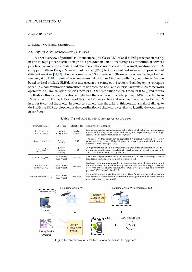
Energies 2017, 10, 1595 3 of 24
2. Related Work and Background
2.1. Conflicts Within Storage Systems Use Cases
A brief overview of potential multi-functional Use Cases (UC) related to ESS participation mainlyin low voltage power distribution grids is provided in Table 1 including a classification of servicesper objective and corresponding stakeholder(s). These use cases assume a small/medium scale ESSequipped with an Energy Management System (EMS) to implement and manage the provision ofdifferent services [11,12]. Hence, a multi-use ESS is reached. Those services are deployed eitherremotely (i.e., EMS set-points based on external decision making) or locally (i.e., set-point evaluationbased on local available EMS data) as also used in the examples in Section 4. Both deployments requireto set up a communication infrastructure between the EMS and external systems such as networkoperators (e.g., Transmission System Operator (TSO), Distribution System Operator (DSO)) and meters.To illustrate this a communication architecture that carries out the set-up of an EMS connected to anESS is shown in Figure 1. Besides of this, the EMS sets active and reactive power values to the ESSin order to control the energy injected/consumed from the grid. In this context, a main challenge todeal with the EMS development is the coordination of single-services, thus to identify the occurrenceof conflicts.
Table 1. Typical multi-functional storage system use cases.
Use Case/Name Objective Stakeholder Description & Examples
electric energytime shift/UC1
marketintegration
marketoperator
Economical benefits are maximized. ESS is charged when the spot market pricesare low and during off-peak times and usually discharged when prices are high.It is based on a daily optimization strategy [7].
voltage control/UC2powerquality DSO
The rise of voltage levels can be regulated by injecting reactive power or byconsuming active power. ESS participates in voltage regulation by implementingdifferent control strategies [8,13].
primary controlreserve/UC3
powersystemstability
TSOA high penetration of DER may result in a change of the grid frequency. The ESSparticipates in the frequency regulation by injecting/consuming active power [3,14].Such a service is usually used by the TSO.
peak-shaving/UC4reduction ofsupply cost end user ESS is used to prevent high peaks of consumption. The ESS is discharged when a
load higher than a specific set-point is switch on [15].
minimizationof prices/UC5
reduction ofsupply cost end user
Electricity costs are minimized by an objective function. It takes into accountthe cash received from selling energy and the cash paid for energy consumed.Moreover, forecast on load consumption, DER device generation and electricityprices (e/kWh) are calculated [16].
self-consumption/UC6reduction ofsupply cost end user
Local self-consumption is the main target. The difference of the local generationand demand is charged into the battery and discharged from it when the demandexceeds the local generation [7].
Figure 1. Communication architecture of a multi-use ESS approach.
2.3 Publication C 88
Energies 2017, 10, 1595 4 of 24
A conflict may appear from the simultaneous interaction of stakeholders (e.g., DSO and EnergyMarket Operator (EMO)) orientated services. This may lead to an inefficient behavior of the EMScontroller, as well as to the no provision of committed services. A conflict identification approach thattargets large flexible power system architectures (e.g., virtual power plants, large-scale deploymentof DER) is addressed by the ELECTRA IRP project [6]. In this study, scenarios of controllerconflicts and suggestions for conflict’s resolution are presented. Furthermore, a methodology forconflict identification based on a set of advises such as detailed use case specification, impact ofcontrollers interactions on system stability, classification of conflicts by acceptable and unacceptable,etc. is presented. Against previous concept, this work proposes an engineering support tosemi-automatically identify and resolve controllers conflicts in a specific power system domain:a multi-use storage system. To afford this, a domain expert or user needs to provide informationabout a multi-functional ESS, this process is manually done and is the starting point to proceed with afully-automatic identification of conflicts. Additionally, handling approaches are proposed in the formof code and specific models, a validation and correction of them needs to be done manually by theuser. Moreover, the proposed approach is developed in a generic way to be used in any ESS controlscheme configuration. To this end, the implementation and simulation of services proposed in Table 1is a meaningful first step to analyze the occurrence of potential conflicts and to derive a classificationof causes of conflicts occurrence, this classification is carried out in Section 3.1.
2.2. Storage Systems Application Development
The main steps to be carried out during the development of ESS applications are the design,prototype and realization stages [17,18]. In the first one a conceptual design of the EMS controller iselaborated and verified. It involves a model of the electrical network, the ESS converter controller andcorresponding systems or physical devices (e.g., photovoltaic inverter, load profile, Supervisory Controland Data Acquisition (SCADA)). As a sequel, the design of control algorithms to fulfill a set ofservices requirements is carried out. Those requirements vary depending on time-scale and accuracy.For instance, a voltage control use case requires a response time of at least 60 s and a maximum voltagedeviation of±6.5%. Following this, a proof of concept is carried out to validate the initial specifications.This is mainly done in an offline simulator for power system simulations (e.g., Matlab/Simulink,DlgSILENT/PowerFactory) [19]. After the conceptual design is verified, a prototype is realized.Often the transformation from concept design into a prototype entails communication delays ornon-linearities issues. Then, an iterative refinement of the algorithms is carried out. The realizationstage requires testing the validated prototype in a real environment.
This work is focused on the analysis of requirements at the design phase with the aimof identifying conflicts between control algorithms. Additionally, possible handling solutionsfor those conflicts are advised and deployed during software and following hardware-basedtests (e.g., pure offline and Controller-Hardware-in-the-Loop (CHIL) simulations). An earlyconflict detection would enable a free-of-conflict storage system application at the design phase,before the elaboration of any hands-on work such as control algorithms models implementation.Additionally, this would also support the selection of the right control scheme for a multi-functionalESS approach.
2.3. Rapid Prototyping of ESS Applications
Ontologies abstract information of a specific domain with the aim to represent objects, type ofobjects, and their semantic relations in a formal machine-readable way. Additionally, a set of inferencerules and restrictions on relations are defined to support semantic interpretation [20]. This kindof modeling approach has also already been successfully applied to the domain of power systems:for example, reference [21] has designed an ontology to model the coordination between buildingenergy management systems and smart grids stakeholders in a demand response context. The mainentities to be modeled are communication technologies, service interfaces and grid structure. Thanks
2.3 Publication C 89

Energies 2017, 10, 1595 5 of 24
to reasoning techniques, a matching of services and their communication technology is achieved.Besides of this, reference [22] develops an ontology by applying fuzzy theory to diagnostic faults inpower transformers, demonstrating that fuzzy ontology identifies faults that are unidentifiable by abasic ontology model. The mentioned studies highlight the use of key features of ontologies such asautomatic reasoning and share of knowledge in the smart grid domain. In contrast to the mentionedstudies, this paper is focused on a specific power system domain: multi-use storage systems connectedto low voltage power distribution grids. This system is analyzed, resulting in the development of anontology that targets controllers conflicts. This ontology is also used to handle the localized conflicts.To achieve this, data consistency checking and inference of knowledge—assets of ontologies [23]—areperformed.
A further interesting modeling approach—Model-Driven Design (MDD) or Model-DrivenEngineering (MDE)—focuses on an abstract representation of knowledge by the usage of modelsspecification [24]. An advantage of this is to support the development of software applications byimproving the interoperability between systems. In this context, two main types of transformationsare considered: (i) Model-to-Text transformation (M2T) that generates executable source code,documentation or other text files from source models; and (ii) Model-to-Model transformation (M2M)that transforms source models into specific target models by executing pre-defined transformationrules [25]. MDE and SGAM are lately employed in smart grid projects to gain a commonunderstanding of smart grid architecture elements [26] and to foster the rapid prototyping of smartgrid applications [18,27]. In this context, the proposed ontology is aligned to the SGAM model andexploited by the means of M2T techniques.
In summary, this paper joins concepts from MDE and ontologies to improve the rapid prototypingof multi-use ESS applications and to handle conflicts derived from the overlapping of correspondingapplications. Hence, an engineering support consisting in a methodology is derived.
3. Ontologies for Multi-Use ESS Conflicts Identification
The scope of this section is to introduce a methodology supporting the identification of multi-useEES conflicts. This process is carried out during the specification phase of controllers, resulting in anappropriate control scheme to be implemented. To this end, a classification of conflicts based on theircauses is proposed. Additionally, this classification is formally modeled by ontologies resulting in anEMS-ontology, a data model that targets conflicts identification. As a sequel, reasoning mechanismsare carried out to entail the deduction of conflicts.
3.1. Categorization of Controller Conflicts
The main objective of a multi-functional ESS control is to provide more than one serviceby injecting/consuming active or reactive power (either with locally or remotely connected EMScontrollers). It is illustrated in Figure 2, where an EMS sets the power to be injected/consumed by theESS, additionally the EMS communicates with external systems (e.g., DSO, TSO, EMO) depending onthe configuration of the EMS controllers. The interaction between those controllers could lead to anundesired behavior of the ESS system and a non-provision of the corresponding service. Because ofthis, the reason(s) causing the conflicts need to be identified and investigated. Table 2 provides acorresponding overview of typical controller conflicts resulting from the multi-use of ESS (extendedfrom [11]).
2.3 Publication C 90
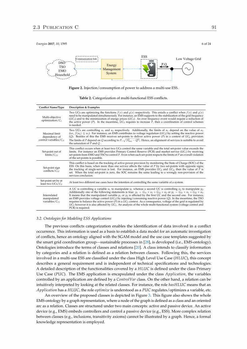
Energies 2017, 10, 1595 6 of 24
Figure 2. Injection/consumption of power to address a multi-use ESS.
Table 2. Categorization of multi-functional ESS conflicts.
Conflict Name/Type Description & Examples
Multi-objectiveoptimization/CI
Two UCs are optimizing the functions f (x) and g(x) respectively. This entails a conflict when f (x) and g(x)need to be manipulated simultaneously. For instance, an EMS supports to the stabilization of the grid frequency(UC3) and to the minimization of energy prices (UC5). An over frequency event would require a reduction ofthe active power (P). In the meantime, UC5 requires to increase P, then a coordination of control schemesis needed.
Maximal limitdependency of
control variables/CI I
Two UCs are controlling u1 and u2 respectively. Additionally, the limits of u1 depend on the value of u2(i.e., f (u2) ≶ u1). For instance, an EMS contributes to voltage regulation (UC2) by setting the reactive power(Q). Besides of this the EMS receives set-points to deliver active power (P) in a context of UC6 provision.The limits of P depend on Q according to P<
√|S2
max −Q2|. Hence, an alignment of services is suitable to avoidthe saturation of P and Q .
Set-point out oflimits/CI I I
This conflict occurs when at least two UCs control the same variable and the total set-point value exceeds thelimits. For instance an EMS provides Primary Control Reserve (PCR) and market service (UC1) by receivingset-points from EMO and TSO to control P. Even when each set-point respects the limits of P an overall violationof the set-points is possible.
Set-point signconflicts/CIV
This conflict is based on the tracking of active power provision by monitoring the State of Charge (SOC) of theESS. On this basis, when more than one service affects the value of P by two set-points with opposite signs,the tracking of single-services is lost. For instance, an EMS provides UC6 and UC4, then the value of P isset. When the total set-point is zero, the SOC remains the same leading to a wrongly non-provision of theservices conclusion.
Set-point set by atleast two UCs/CV
At least two different use cases have the intention of controlling the same variable of a system.
Interrelatedmanipulatedvariables/CVI
A UC is controlling a variable u1 to manipulate y1 whereas a second UC is controlling u2 to manipulate y2.Additionally one of the following statements is true: y1 = G11 × u1 + G12 × u2 or y2 = G21 × u1 + G22 × u2.It means that the manipulated variable y1 or y2 is affected by the first UC and the second one. For instance,an EMS provides voltage control (UC2) by injecting/consuming reactive power (Q). In the meantime, the TSOrequires to balance the active power (P) in a UC3 context. As a consequence, voltage of the grid is regulated byUC2 however it is also affected by UC3. An analysis of the whole multi-functional system (voltage control andPCR) is required.
3.2. Ontologies for Modeling ESS Applications
The previous conflicts categorization enables the identification of data involved in a conflictoccurrence. This information is used as a basis to establish a data model for an automatic investigationof conflicts, hence an ontology aligned with the SGAM model and the use case templates suggested bythe smart grid coordination group—sustainable processes in [28], is developed (i.e., EMS-ontology).Ontologies introduce the terms of classes and relations [20]. A class intends to classify informationby categories and a relation is defined as a relation between classes. Following this, the servicesinvolved in a multi-use ESS are classified under the class High Level Use Case (HLUC), this conceptdescribes a general requirement and is independent of technical specifications and technologies.A detailed description of the functionalities covered by a HLUC is defined under the class PrimaryUse Case (PUC). The EMS application is encapsulated under the class Application, the variablescontrolled by an application are defined by a ControlVar class. On the other hand, a relation can beintuitively interpreted by looking at the related classes. For instance, the role hasHLUC means that anApplication has a HLUC, the role optimize is understood as a PUC regulates/optimizes a variable, etc.
An overview of the proposed classes is depicted in Figure 3. This figure also shows the wholeEMS-ontology by a graph representation, where a node of the graph is defined as a class and an orientedarc as a relation. Classes are structured under two main concepts: active and passive device. An activedevice (e.g., EMS) embeds controllers and control a passive device (e.g., ESS). More complex relationbetween classes (e.g., inclusions, transitivity axioms) cannot be illustrated by a graph. Hence, a formalknowledge representation is employed.
2.3 Publication C 91
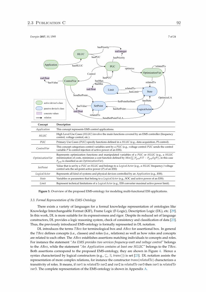
Energies 2017, 10, 1595 7 of 24
Concept Description
Application This concept represents EMS control applications.
HLUC High Level Use Cases (HLUC) involve the main functions covered by an EMS controller (frequencycontrol, voltage control, etc.).
PUC Primary Use Cases (PUC) specify functions defined in a HLUC (e.g., data acquisition, PI control).
ControlVar This concept categorizes control variables sent by a PUC (e.g., voltage control PUC sends the controlvariable P to control injection of active power of an ESS).
OptimizationVarRepresents optimization functions and manipulated variables of a PUC or HLUC (e.g., a HLUCminimization of costs, minimizes a cost function defined by Min(∑ |PgridFiT − PgridEgP|), in this casePgrid is classified as an OptimizationVar).
SetPoint Value that is set by a PUC or HLUC and belongs to a LogicalActor (e.g., a HLUC frequency/voltagecontrol sets the set-point active power (P) of an ESS)
LogicalActor Represents all kind of systems and physical devices controlled by an Application (e.g., ESS).
State Variables or parameters that belong to a LogicalActor (e.g., SOC and active power of an ESS).
Limit Represent technical limitations of a LogicalActor (e.g., ESS converter maximal active power limit).
Figure 3. Overview of the proposed EMS-ontology for modeling multi-functional ESS applications.
3.3. Formal Representation of the EMS-Ontology
There exists a variety of languages for a formal knowledge representation of ontologies likeKnowledge Interchangeable Format (KIF), Frame Logic (F-Logic), Description Logic (DL), etc. [29].In this work, DL is more suitable for its expressiveness and rigor. Despite its reduced set of languageconstructors, DL provides a logic reasoning system, check of consistency and classification of data [23].Thus, the previously introduced EMS-ontology is formally represented in DL notation.
DL introduces the terms TBox for terminological box and ABox for assertional box. In generalthe TBox defines concepts (i.e., classes) and roles (i.e., relations) as well as how roles and conceptsare related to each other. The ABox establishes assertions matching individuals to concepts and roles.For instance the statement “An EMS provides two services frequency-watt and voltage control” belongsto the ABox, while the statement “An Application contains at least one HLUC” belongs to the TBox.Both assertions correspond to the proposed EMS-ontology, they are shown in Figure 4. Hence asyntax characterized by logical constructors (e.g., v, ∃, trans()) is set [23]. DL notation assists therepresentation of more complex relations, for instance the constructor trans(relatedTo) characterizes atransitivity of roles. It means, if var1 is relatedTo var2 and var2 is relatedTo var3 then var1 is relatedTovar3. The complete representation of the EMS-ontology is shown in Appendix A.
2.3 Publication C 92
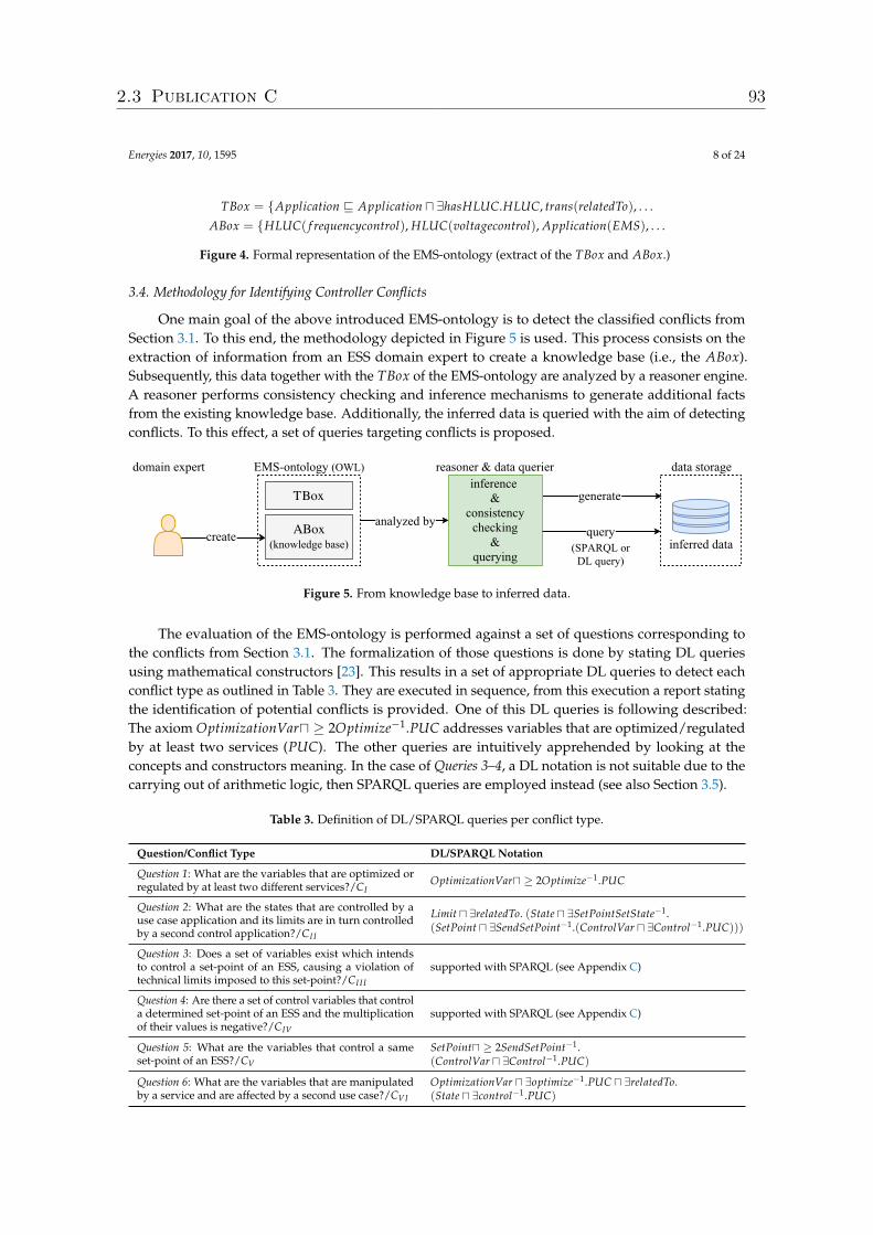
Energies 2017, 10, 1595 8 of 24
TBox = {Application v Application u ∃hasHLUC.HLUC, trans(relatedTo), . . .
ABox = {HLUC( f requencycontrol), HLUC(voltagecontrol), Application(EMS), . . .
Figure 4. Formal representation of the EMS-ontology (extract of the TBox and ABox.)
3.4. Methodology for Identifying Controller Conflicts
One main goal of the above introduced EMS-ontology is to detect the classified conflicts fromSection 3.1. To this end, the methodology depicted in Figure 5 is used. This process consists on theextraction of information from an ESS domain expert to create a knowledge base (i.e., the ABox).Subsequently, this data together with the TBox of the EMS-ontology are analyzed by a reasoner engine.A reasoner performs consistency checking and inference mechanisms to generate additional factsfrom the existing knowledge base. Additionally, the inferred data is queried with the aim of detectingconflicts. To this effect, a set of queries targeting conflicts is proposed.
Figure 5. From knowledge base to inferred data.
The evaluation of the EMS-ontology is performed against a set of questions corresponding tothe conflicts from Section 3.1. The formalization of those questions is done by stating DL queriesusing mathematical constructors [23]. This results in a set of appropriate DL queries to detect eachconflict type as outlined in Table 3. They are executed in sequence, from this execution a report statingthe identification of potential conflicts is provided. One of this DL queries is following described:The axiom OptimizationVaru ≥ 2Optimize−1.PUC addresses variables that are optimized/regulatedby at least two services (PUC). The other queries are intuitively apprehended by looking at theconcepts and constructors meaning. In the case of Queries 3–4, a DL notation is not suitable due to thecarrying out of arithmetic logic, then SPARQL queries are employed instead (see also Section 3.5).
Table 3. Definition of DL/SPARQL queries per conflict type.
Question/Conflict Type DL/SPARQL Notation
Question 1: What are the variables that are optimized orregulated by at least two different services?/CI
OptimizationVaru ≥ 2Optimize−1.PUC
Question 2: What are the states that are controlled by ause case application and its limits are in turn controlledby a second control application?/CI I
Limit u ∃relatedTo. (State u ∃SetPointSetState−1.(SetPoint u ∃SendSetPoint−1.(ControlVar u ∃Control−1.PUC)))
Question 3: Does a set of variables exist which intendsto control a set-point of an ESS, causing a violation oftechnical limits imposed to this set-point?/CI I I
supported with SPARQL (see Appendix C)
Question 4: Are there a set of control variables that controla determined set-point of an ESS and the multiplicationof their values is negative?/CIV
supported with SPARQL (see Appendix C)
Question 5: What are the variables that control a sameset-point of an ESS?/CV
SetPointu ≥ 2SendSetPoint−1.(ControlVar u ∃Control−1.PUC)
Question 6: What are the variables that are manipulatedby a service and are affected by a second use case?/CVI
OptimizationVar u ∃optimize−1.PUC u ∃relatedTo.(State u ∃control−1.PUC)
2.3 Publication C 93
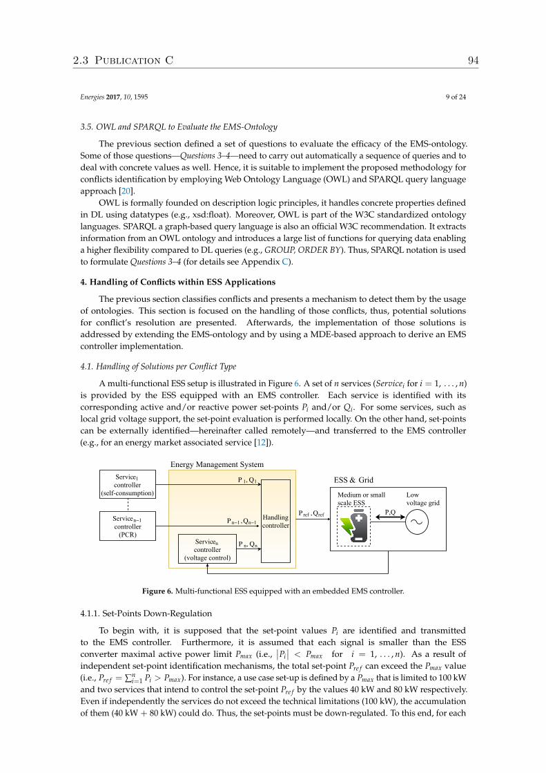
Energies 2017, 10, 1595 9 of 24
3.5. OWL and SPARQL to Evaluate the EMS-Ontology
The previous section defined a set of questions to evaluate the efficacy of the EMS-ontology.Some of those questions—Questions 3–4—need to carry out automatically a sequence of queries and todeal with concrete values as well. Hence, it is suitable to implement the proposed methodology forconflicts identification by employing Web Ontology Language (OWL) and SPARQL query languageapproach [20].
OWL is formally founded on description logic principles, it handles concrete properties definedin DL using datatypes (e.g., xsd:float). Moreover, OWL is part of the W3C standardized ontologylanguages. SPARQL a graph-based query language is also an official W3C recommendation. It extractsinformation from an OWL ontology and introduces a large list of functions for querying data enablinga higher flexibility compared to DL queries (e.g., GROUP, ORDER BY). Thus, SPARQL notation is usedto formulate Questions 3–4 (for details see Appendix C).
4. Handling of Conflicts within ESS Applications
The previous section classifies conflicts and presents a mechanism to detect them by the usageof ontologies. This section is focused on the handling of those conflicts, thus, potential solutionsfor conflict’s resolution are presented. Afterwards, the implementation of those solutions isaddressed by extending the EMS-ontology and by using a MDE-based approach to derive an EMScontroller implementation.
4.1. Handling of Solutions per Conflict Type
A multi-functional ESS setup is illustrated in Figure 6. A set of n services (Servicei for i = 1, . . . , n)is provided by the ESS equipped with an EMS controller. Each service is identified with itscorresponding active and/or reactive power set-points Pi and/or Qi. For some services, such aslocal grid voltage support, the set-point evaluation is performed locally. On the other hand, set-pointscan be externally identified—hereinafter called remotely—and transferred to the EMS controller(e.g., for an energy market associated service [12]).
Figure 6. Multi-functional ESS equipped with an embedded EMS controller.
4.1.1. Set-Points Down-Regulation
To begin with, it is supposed that the set-point values Pi are identified and transmittedto the EMS controller. Furthermore, it is assumed that each signal is smaller than the ESSconverter maximal active power limit Pmax (i.e.,
∣∣Pi∣∣ < Pmax for i = 1, . . . , n). As a result of
independent set-point identification mechanisms, the total set-point Pre f can exceed the Pmax value(i.e., Pre f = ∑n
i=1 Pi > Pmax). For instance, a use case set-up is defined by a Pmax that is limited to 100 kWand two services that intend to control the set-point Pre f by the values 40 kW and 80 kW respectively.Even if independently the services do not exceed the technical limitations (100 kW), the accumulationof them (40 kW + 80 kW) could do. Thus, the set-points must be down-regulated. To this end, for each
2.3 Publication C 94

Energies 2017, 10, 1595 10 of 24
service a corresponding priority is defined. Assuming that the service n has the lowest priority if themaximal limit is exceeded, the set-point Pn is down-regulated as
Pn−new = sgn(Pn)
∣∣∣∣Pmax −n−1
∑i=1
∣∣Pi∣∣∣∣∣∣ (1)
Similarly, if still the sum is greater than Pmax, then Pn is set to zero and the next least-prior term isdown-regulated. Hence, the corresponding services are partially provided. This handling solutioncorresponds to the conflict CI I I .
4.1.2. Converter PQ Range Limiter
The handling solution proposed in the previous section makes it possible to define the referenceESS active and reactive power such that all the services are considered
Pre f =n
∑i=1
Pi−new, Qre f =n
∑i=1
Qi−new (2)
Consequently, the reference apparent power is defined by
Sre f =√
P2re f + Q2
re f (3)
This value is limited by the ESS apparent power limit (Smax). Although all the individual serviceset-points associated with active and/or reactive power provision are smaller than the maximal limits(i.e., Pi−new < Pmax and Qi−new < Qmax for i = 1, . . . , n) still the ESS apparent power limit can beviolated i.e, Sre f > Smax exemplifying a conflict CI I . Thus, the corresponding Pre f and Qre f must bedown-regulated such that Sre f = Smax. A potential solution is detailed in the literature [30].
4.1.3. SOC Estimation and Capacity Allocation
In order to illustrate type CIV conflict occurrence in this application, let the service set-points be
Pi 6= 0 and Pj 6= 0 for i, j = 1, . . . , n such that for any (i, j), i 6= j and Pi · Pj < 0 (4)
This means that, the set-points Pi and Pj, targeting the active power value of an ESS, have oppositesigns. This corresponds to the conflict CIV . In such a conflicted scenario, it is important to virtuallytrack the impact of each set-point. This is realized by virtually allocating a portion of the ESS capacityto each service. Furthermore, a state of charge estimator must be implemented for each capacityportion. State of charge estimator evaluates the SOC changes by considering the allocated capacity,battery voltage measurement and the power set-point defined by Equation (4). A detailed descriptionof this handling solution is described in [30].
4.1.4. Use Case Specific Solutions
A general solution can not be encouraged for conflict CVI . Hence, the handling solution must beemployed depending on the use case specification/requirement. For instance, a multi-functional ESSprovides services which define the Pre f . Additionally, the Point of Common Coupling (PCC) voltagesupport is also offered, see Figure 1. Voltage support has to be provided so that the PCC voltage Vpcc
does not violate the limits (Vupper and Vlower) defined by the DSO. The steady state PCC voltage interms of active/reactive power injected by the ESS is expressed by
Vpcc = V −RPre f + jωLQre f
V(5)
2.3 Publication C 95
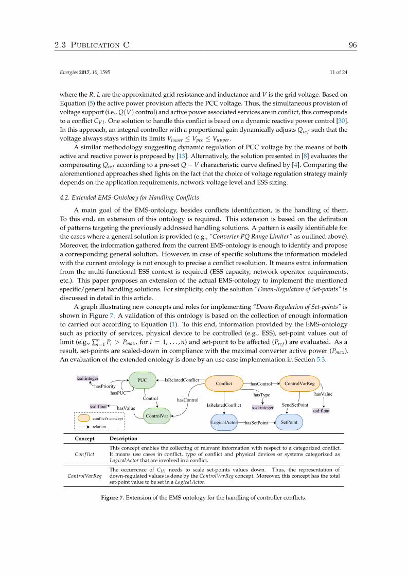
Energies 2017, 10, 1595 11 of 24
where the R, L are the approximated grid resistance and inductance and V is the grid voltage. Based onEquation (5) the active power provision affects the PCC voltage. Thus, the simultaneous provision ofvoltage support (i.e., Q(V) control) and active power associated services are in conflict, this correspondsto a conflict CVI . One solution to handle this conflict is based on a dynamic reactive power control [30].In this approach, an integral controller with a proportional gain dynamically adjusts Qre f such that thevoltage always stays within its limits Vlower ≤ Vpcc ≤ Vupper.
A similar methodology suggesting dynamic regulation of PCC voltage by the means of bothactive and reactive power is proposed by [13]. Alternatively, the solution presented in [8] evaluates thecompensating Qre f according to a pre-set Q−V characteristic curve defined by [4]. Comparing theaforementioned approaches shed lights on the fact that the choice of voltage regulation strategy mainlydepends on the application requirements, network voltage level and ESS sizing.
4.2. Extended EMS-Ontology for Handling Conflicts
A main goal of the EMS-ontology, besides conflicts identification, is the handling of them.To this end, an extension of this ontology is required. This extension is based on the definitionof patterns targeting the previously addressed handling solutions. A pattern is easily identifiable forthe cases where a general solution is provided (e.g., “Converter PQ Range Limiter” as outlined above).Moreover, the information gathered from the current EMS-ontology is enough to identify and proposea corresponding general solution. However, in case of specific solutions the information modeledwith the current ontology is not enough to precise a conflict resolution. It means extra informationfrom the multi-functional ESS context is required (ESS capacity, network operator requirements,etc.). This paper proposes an extension of the actual EMS-ontology to implement the mentionedspecific/general handling solutions. For simplicity, only the solution “Down-Regulation of Set-points” isdiscussed in detail in this article.
A graph illustrating new concepts and roles for implementing “Down-Regulation of Set-points” isshown in Figure 7. A validation of this ontology is based on the collection of enough informationto carried out according to Equation (1). To this end, information provided by the EMS-ontologysuch as priority of services, physical device to be controlled (e.g., ESS), set-point values out oflimit (e.g., ∑n
i=1 Pi > Pmax, for i = 1, . . . , n) and set-point to be affected (Pre f ) are evaluated. As aresult, set-points are scaled-down in compliance with the maximal converter active power (Pmax).An evaluation of the extended ontology is done by an use case implementation in Section 5.3.
Concept Description
Con f lictThis concept enables the collecting of relevant information with respect to a categorized conflict.It means use cases in conflict, type of conflict and physical devices or systems categorized asLogicalActor that are involved in a conflict.
ControlVarRegThe occurrence of CI I I needs to scale set-points values down. Thus, the representation ofdown-regulated values is done by the ControlVarReg concept. Moreover, this concept has the totalset-point value to be set in a LogicalActor.
Figure 7. Extension of the EMS-ontology for the handling of controller conflicts.
2.3 Publication C 96
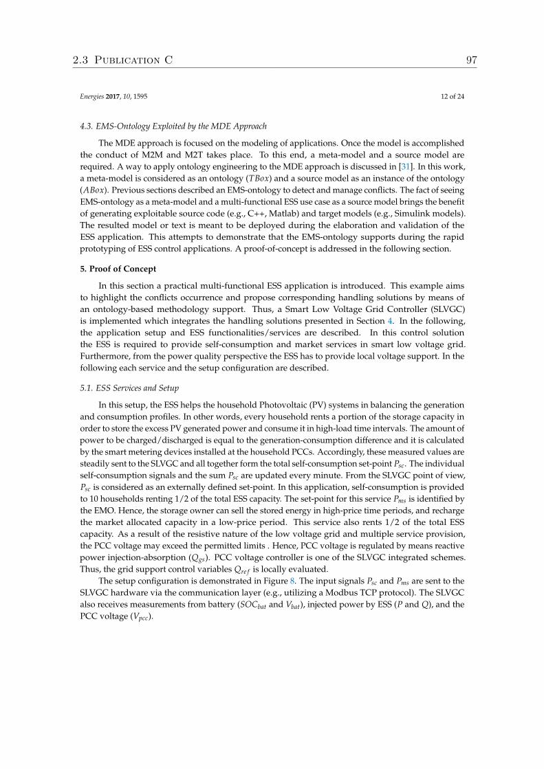
Energies 2017, 10, 1595 12 of 24
4.3. EMS-Ontology Exploited by the MDE Approach
The MDE approach is focused on the modeling of applications. Once the model is accomplishedthe conduct of M2M and M2T takes place. To this end, a meta-model and a source model arerequired. A way to apply ontology engineering to the MDE approach is discussed in [31]. In this work,a meta-model is considered as an ontology (TBox) and a source model as an instance of the ontology(ABox). Previous sections described an EMS-ontology to detect and manage conflicts. The fact of seeingEMS-ontology as a meta-model and a multi-functional ESS use case as a source model brings the benefitof generating exploitable source code (e.g., C++, Matlab) and target models (e.g., Simulink models).The resulted model or text is meant to be deployed during the elaboration and validation of theESS application. This attempts to demonstrate that the EMS-ontology supports during the rapidprototyping of ESS control applications. A proof-of-concept is addressed in the following section.
5. Proof of Concept
In this section a practical multi-functional ESS application is introduced. This example aimsto highlight the conflicts occurrence and propose corresponding handling solutions by means ofan ontology-based methodology support. Thus, a Smart Low Voltage Grid Controller (SLVGC)is implemented which integrates the handling solutions presented in Section 4. In the following,the application setup and ESS functionalities/services are described. In this control solutionthe ESS is required to provide self-consumption and market services in smart low voltage grid.Furthermore, from the power quality perspective the ESS has to provide local voltage support. In thefollowing each service and the setup configuration are described.
5.1. ESS Services and Setup
In this setup, the ESS helps the household Photovoltaic (PV) systems in balancing the generationand consumption profiles. In other words, every household rents a portion of the storage capacity inorder to store the excess PV generated power and consume it in high-load time intervals. The amount ofpower to be charged/discharged is equal to the generation-consumption difference and it is calculatedby the smart metering devices installed at the household PCCs. Accordingly, these measured values aresteadily sent to the SLVGC and all together form the total self-consumption set-point Psc. The individualself-consumption signals and the sum Psc are updated every minute. From the SLVGC point of view,Psc is considered as an externally defined set-point. In this application, self-consumption is providedto 10 households renting 1/2 of the total ESS capacity. The set-point for this service Pms is identified bythe EMO. Hence, the storage owner can sell the stored energy in high-price time periods, and rechargethe market allocated capacity in a low-price period. This service also rents 1/2 of the total ESScapacity. As a result of the resistive nature of the low voltage grid and multiple service provision,the PCC voltage may exceed the permitted limits . Hence, PCC voltage is regulated by means reactivepower injection-absorption (Qgs). PCC voltage controller is one of the SLVGC integrated schemes.Thus, the grid support control variables Qre f is locally evaluated.
The setup configuration is demonstrated in Figure 8. The input signals Psc and Pms are sent to theSLVGC hardware via the communication layer (e.g., utilizing a Modbus TCP protocol). The SLVGCalso receives measurements from battery (SOCbat and Vbat), injected power by ESS (P and Q), and thePCC voltage (Vpcc).
2.3 Publication C 97
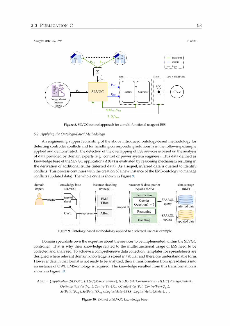
Energies 2017, 10, 1595 13 of 24
Figure 8. SLVGC control approach for a multi-functional usage of ESS.
5.2. Applying the Ontology-Based Methodology
An engineering support consisting of the above introduced ontology-based methodology fordetecting controller conflicts and for handling corresponding solutions is in the following exampleapplied and demonstrated. The detection of the overlapping of ESS services is based on the analysisof data provided by domain experts (e.g., control or power system engineer). This data defined asknowledge base of the SLVGC application (ABox) is evaluated by reasoning mechanism resulting inthe derivation of additional truths (inferred data). As a sequel, inferred data is queried to identifyconflicts. This process continues with the creation of a new instance of the EMS-ontology to manageconflicts (updated data). The whole cycle is shown in Figure 9.
Figure 9. Ontology-based methodology applied to a selected use case example.
Domain specialists own the expertise about the services to be implemented within the SLVGCcontroller. That is why their knowledge related to the multi-functional usage of ESS need to becollected and analyzed. To achieve a comprehensive data collection, templates for spreadsheets aredesigned where relevant domain knowledge is stored in tabular and therefore understandable form.However data in that format is not ready to be analyzed, then a transformation from spreadsheets intoan instance of OWL EMS-ontology is required. The knowledge resulted from this transformation isshown in Figure 10.
ABox = {Application(SLVGC), HLUC(MarketService), HLUC(Sel f Consumption), HLUC(VoltageControl),OptimizationVar(Vpcc), ControlVar(Pms), ControlVar(Psc), ControlVar(Qgs),
SetPoint(Pre f ), SetPoint(Qre f ), LogicalActor(ESS), LogicalActor(Meter), . . .
Figure 10. Extract of SLVGC knowledge base.
2.3 Publication C 98
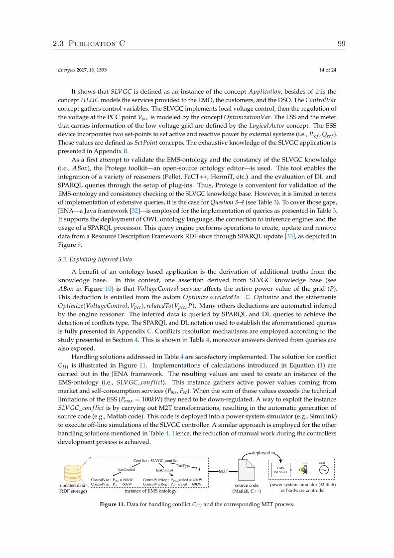
Energies 2017, 10, 1595 14 of 24
It shows that SLVGC is defined as an instance of the concept Application, besides of this theconcept HLUC models the services provided to the EMO, the customers, and the DSO. The ControlVarconcept gathers control variables. The SLVGC implements local voltage control, then the regulation ofthe voltage at the PCC point Vpcc is modeled by the concept OptimizationVar. The ESS and the meterthat carries information of the low voltage grid are defined by the LogicalActor concept. The ESSdevice incorporates two set-points to set active and reactive power by external systems (i.e., Pre f , Qre f ).Those values are defined as SetPoint concepts. The exhaustive knowledge of the SLVGC application ispresented in Appendix B.
As a first attempt to validate the EMS-ontology and the constancy of the SLVGC knowledge(i.e., ABox), the Protege toolkit—an open-source ontology editor—is used. This tool enables theintegration of a variety of reasoners (Pellet, FaCT++, HermiT, etc.) and the evaluation of DL andSPARQL queries through the setup of plug-ins. Thus, Protege is convenient for validation of theEMS-ontology and consistency checking of the SLVGC knowledge base. However, it is limited in termsof implementation of extensive queries, it is the case for Question 3–4 (see Table 3). To cover those gaps,JENA—a Java framework [32]—is employed for the implementation of queries as presented in Table 3.It supports the deployment of OWL ontology language, the connection to inference engines and theusage of a SPARQL processor. This query engine performs operations to create, update and removedata from a Resource Description Framework RDF store through SPARQL update [33], as depicted inFigure 9.
5.3. Exploiting Inferred Data
A benefit of an ontology-based application is the derivation of additional truths from theknowledge base. In this context, one assertion derived from SLVGC knowledge base (seeABox in Figure 10) is that VoltageControl service affects the active power value of the grid (P).This deduction is entailed from the axiom Optimize ◦ relatedTo v Optimize and the statementsOptimize(VoltageControl, Vpcc), relatedTo(Vpcc, P). Many others deductions are automated inferredby the engine reasoner. The inferred data is queried by SPARQL and DL queries to achieve thedetection of conflicts type. The SPARQL and DL notation used to establish the aforementioned queriesis fully presented in Appendix C. Conflicts resolution mechanisms are employed according to thestudy presented in Section 4. This is shown in Table 4, moreover answers derived from queries arealso exposed.
Handling solutions addressed in Table 4 are satisfactory implemented. The solution for conflictCI I I is illustrated in Figure 11. Implementations of calculations introduced in Equation (1) arecarried out in the JENA framework. The resulting values are used to create an instance of theEMS-ontology (i.e., SLVGC_con f lict). This instance gathers active power values coming frommarket and self-consumption services (Pms, Psc). When the sum of those values exceeds the technicallimitations of the ESS (Pmax = 100kW) they need to be down-regulated. A way to exploit the instanceSLVGC_con f lict is by carrying out M2T transformations, resulting in the automatic generation ofsource code (e.g., Matlab code). This code is deployed into a power system simulator (e.g., Simulink)to execute off-line simulations of the SLVGC controller. A similar approach is employed for the otherhandling solutions mentioned in Table 4. Hence, the reduction of manual work during the controllersdevelopment process is achieved.
Figure 11. Data for handling conflict CI I I and the corresponding M2T process.
2.3 Publication C 99
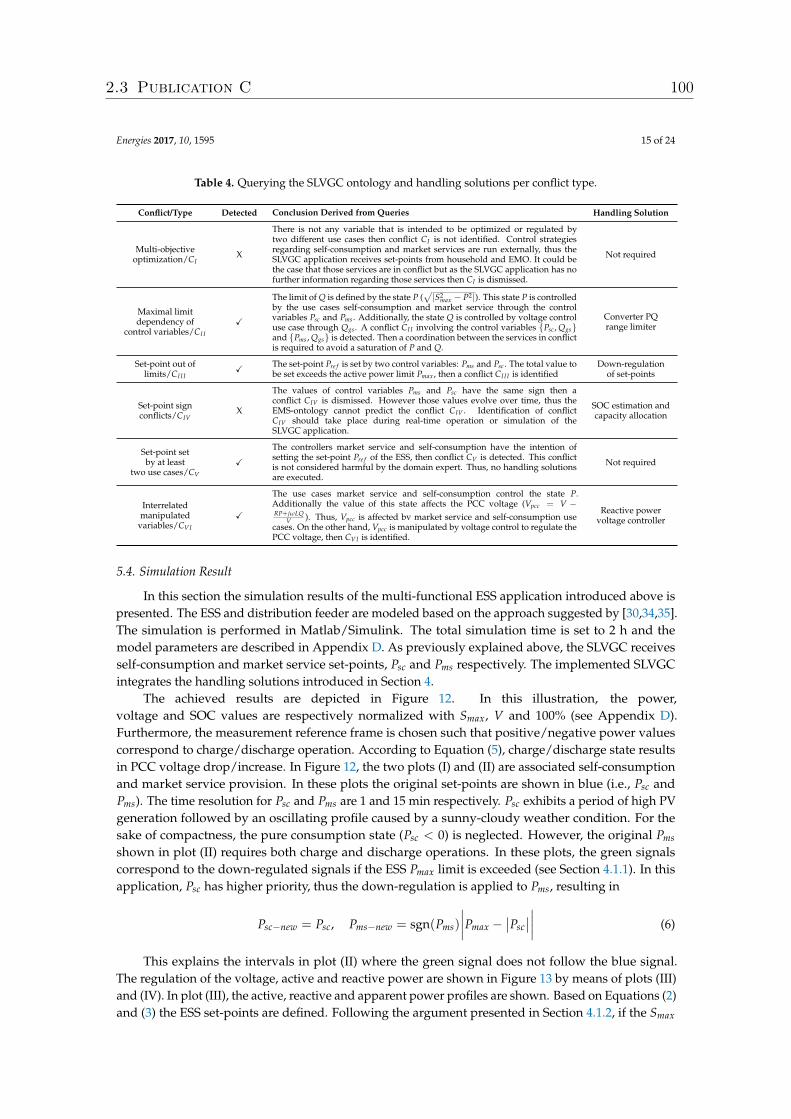
Energies 2017, 10, 1595 15 of 24
Table 4. Querying the SLVGC ontology and handling solutions per conflict type.
Conflict/Type Detected Conclusion Derived from Queries Handling Solution
Multi-objectiveoptimization/CI
X
There is not any variable that is intended to be optimized or regulated bytwo different use cases then conflict CI is not identified. Control strategiesregarding self-consumption and market services are run externally, thus theSLVGC application receives set-points from household and EMO. It could bethe case that those services are in conflict but as the SLVGC application has nofurther information regarding those services then CI is dismissed.
Not required
Maximal limitdependency of
control variables/CI I
X
The limit of Q is defined by the state P (√|S2
max − P2|). This state P is controlledby the use cases self-consumption and market service through the controlvariables Psc and Pms . Additionally, the state Q is controlled by voltage controluse case through Qgs . A conflict CI I involving the control variables {Psc , Qgs}and {Pms , Qgs} is detected. Then a coordination between the services in conflictis required to avoid a saturation of P and Q.
Converter PQrange limiter
Set-point out oflimits/CI I I
X The set-point Pre f is set by two control variables: Pms and Psc . The total value tobe set exceeds the active power limit Pmax , then a conflict CI I I is identified
Down-regulationof set-points
Set-point signconflicts/CIV
X
The values of control variables Pms and Psc have the same sign then aconflict CIV is dismissed. However those values evolve over time, thus theEMS-ontology cannot predict the conflict CIV . Identification of conflictCIV should take place during real-time operation or simulation of theSLVGC application.
SOC estimation andcapacity allocation
Set-point setby at least
two use cases/CV
XThe controllers market service and self-consumption have the intention ofsetting the set-point Pre f of the ESS, then conflict CV is detected. This conflictis not considered harmful by the domain expert. Thus, no handling solutionsare executed.
Not required
Interrelatedmanipulated
variables/CVI
X
The use cases market service and self-consumption control the state P.Additionally the value of this state affects the PCC voltage (Vpcc = V −RP+jωLQ
V ). Thus, Vpcc is affected bv market service and self-consumption usecases. On the other hand, Vpcc is manipulated by voltage control to regulate thePCC voltage, then CVI is identified.
Reactive powervoltage controller
5.4. Simulation Result
In this section the simulation results of the multi-functional ESS application introduced above ispresented. The ESS and distribution feeder are modeled based on the approach suggested by [30,34,35].The simulation is performed in Matlab/Simulink. The total simulation time is set to 2 h and themodel parameters are described in Appendix D. As previously explained above, the SLVGC receivesself-consumption and market service set-points, Psc and Pms respectively. The implemented SLVGCintegrates the handling solutions introduced in Section 4.
The achieved results are depicted in Figure 12. In this illustration, the power,voltage and SOC values are respectively normalized with Smax, V and 100% (see Appendix D).Furthermore, the measurement reference frame is chosen such that positive/negative power valuescorrespond to charge/discharge operation. According to Equation (5), charge/discharge state resultsin PCC voltage drop/increase. In Figure 12, the two plots (I) and (II) are associated self-consumptionand market service provision. In these plots the original set-points are shown in blue (i.e., Psc andPms). The time resolution for Psc and Pms are 1 and 15 min respectively. Psc exhibits a period of high PVgeneration followed by an oscillating profile caused by a sunny-cloudy weather condition. For thesake of compactness, the pure consumption state (Psc < 0) is neglected. However, the original Pms
shown in plot (II) requires both charge and discharge operations. In these plots, the green signalscorrespond to the down-regulated signals if the ESS Pmax limit is exceeded (see Section 4.1.1). In thisapplication, Psc has higher priority, thus the down-regulation is applied to Pms, resulting in
Psc−new = Psc, Pms−new = sgn(Pms)
∣∣∣∣Pmax −∣∣Psc
∣∣∣∣∣∣ (6)
This explains the intervals in plot (II) where the green signal does not follow the blue signal.The regulation of the voltage, active and reactive power are shown in Figure 13 by means of plots (III)and (IV). In plot (III), the active, reactive and apparent power profiles are shown. Based on Equations (2)and (3) the ESS set-points are defined. Following the argument presented in Section 4.1.2, if the Smax
2.3 Publication C 100
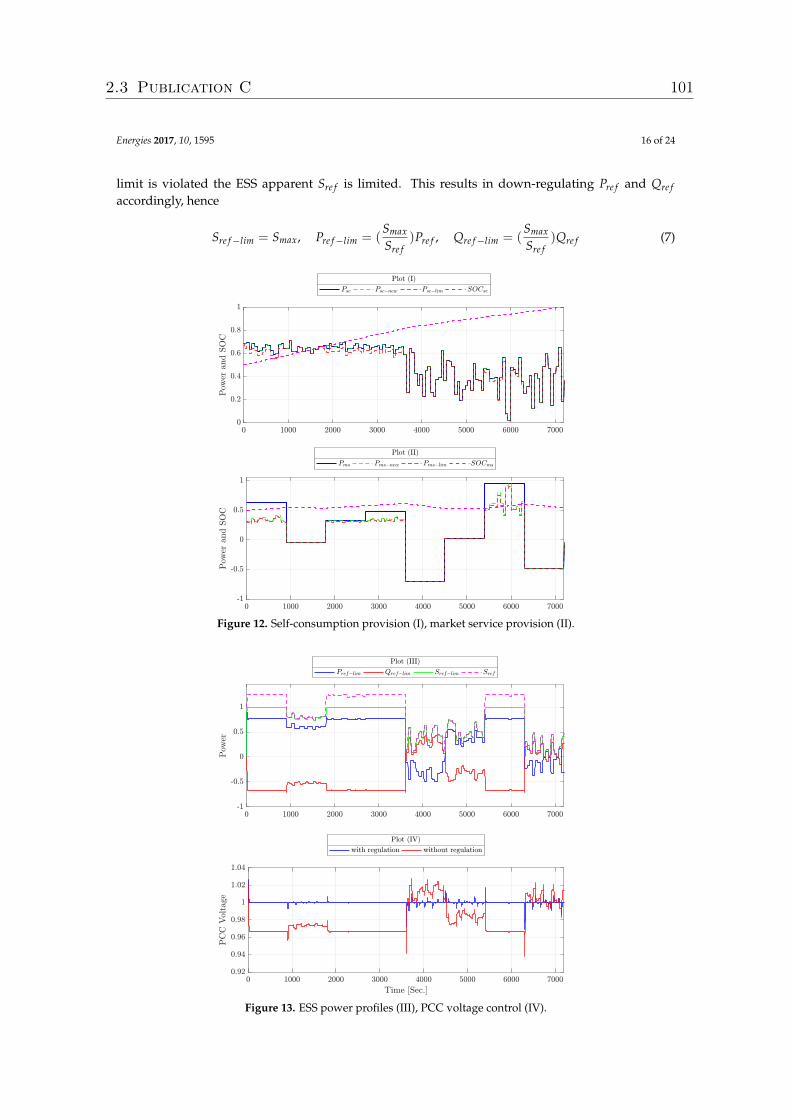
Energies 2017, 10, 1595 16 of 24
limit is violated the ESS apparent Sre f is limited. This results in down-regulating Pre f and Qre faccordingly, hence
Sre f−lim = Smax, Pre f−lim = (Smax
Sre f)Pre f , Qre f−lim = (
Smax
Sre f)Qre f (7)
Figure 12. Self-consumption provision (I), market service provision (II).
Figure 13. ESS power profiles (III), PCC voltage control (IV).
2.3 Publication C 101
Energies 2017, 10, 1595 17 of 24
This corresponds to the intervals where the green signal is limited to 1 in plot (III). As aconsequence of down-regulating Pre f to Pre f−lim, the associated market and self-consumption signalsare also scaled down with the same ratio as in Equation (7), resulting in Psc−lim and Pms−lim.These signals are shown in red in plots (I) and (II). Sequentially, these final services set-points arefeedbacked to state of charge estimation schemes mentioned in Section 4.1.3. The estimated state ofcharge evolution is depicted in plots (I) and (II) reflecting the availability of allocated capacity for eachservice. Last but not least, the reactive power set-point Qre f is evaluated by the PCC voltage controllerwhich is implemented based on the strategy in [30]. By construction, Qre f always has an oppositesign compared to Pre f . The PCC voltage controller impact can be observed in plot (IV). For instance,when Pre f > 0 the ESS is charging. Thus, the PCC voltage drops from its nominal value. Consequently,the controller reacts by adjusting Qre f < 0 such that PCC voltage regains the nominal value as it’ssteady state.
6. Conclusions and Future Work
With the large-scale integration DER into power distribution grids new services provided byESS are required, thus the development of a corresponding multi-functional usage of them is nowbecoming a reality. This trend faces a difficult issue derived from the overlapping between controltargets. Thus, an engineering support for an early detection and handling of conflicts during therequirements analysis of control structure is necessary. This methodology will enable a correct planningand management of ESS control applications.
The main basis of this solution lays on the definition of an ontology (i.e., EMS-ontology),overly simplified to identify and resolve conflicts. The presented EMS-ontology based approachdemonstrates that an early requirements analysis of the control structure enables the identificationand handling of conflicts. Moreover, a convenient and user-friendly way to gather knowledge fromdomain experts is also tackled by proposing a spreadsheet template. This knowledge is modeled bymeans of ontologies, hence reasoning mechanisms enable the inference of new facts. This resultedinformation is queried by predefined queries targeting conflicts classified by types (see Tables 2and 3). Additionally, a set of handling solutions per conflicts type is encouraged, this motivates asemi-automatic generation of code to support conflicts resolution and to be implemented during thedevelopment of the system. This enables the rapid prototyping of ESS applications and a preventivecorrection of handling of conflicts before any practical implementation.
Model-based strategies to design the requirements of power systems are addressed by differentstandards and approaches. However, information gathered by them are not enough for a full conflictidentification. A well-known approach to specify and structure the requirements of smart gridapplications is defined by SGAM. This approach is being used in divers smart grids projects [26].Despite of this, a full conflict detection is not totally ensured [11]. Additionally, the use casemethodology introduced by IEC 62559 [10] gives the basis to specify requirements for energy systemscontrol applications, but the identification of conflicts is not really addressed. In contrast with thosemethodologies, the engineering support approach defined by this paper does not provide a model fordesigning all the aspects of power systems applications. This motivates to concentrate future work onthe alignment of the proposed approach with power system modeling methodologies such as SGAMand IEC 62559. This would improve the development chain of control applications, enabling a fulldescription of power system application as well as an automatic conflict identification from the verybeginning of the development process. Furthermore, the support of interoperability between the EMSwith external systems such as TSO and EMO to import knowledge about controllers implementedremotely to the EMS should be assured. This entails the alignment of the EMS-ontology with othersmart grid information models such as IEC 61850 and Common Information Model (IEC 61970),both are standards to improve the interoperability in electric power systems [36].
The literature shows only first preliminary ideas that addresses conflicts within a multi-use ESScontext. An approach that targets the identification of conflicts within electric energy systems is
2.3 Publication C 102
Energies 2017, 10, 1595 18 of 24
studied in [37], this study recommends the use of the language Multi-level Flow Modeling (MFM) tomodel the requirements of control structures. Additionally, this approach is aligned to the IEC 62559in the scope of the ELECTRA IRP project [38]. However, because of the large range of power systemapplications covered by this solution, a correct effectiveness and also its limitations are unknown.Compared with this approach, not only the identification but the handling of conflicts are addressedby the EMS-ontology. Moreover, this ontology targets a restricted domain: multi-use ESS, then theobjective design criteria is very well defined by a set of selected questions, as outlined in Table 3. On theother hand, a correct design of ontologies depends on the initial knowledge base, the EMS-ontologyis built from use cases presented in Table 1, hence is not exhaustive for all the conflicts derived frommulti-functional storage systems. Thus an efficient EMS-ontology would require the knowledgeof a larger list of use cases. This may entail the extension of handling solutions resulting in anevolution of the ontology as well. Hence, the designing of the EMS-ontology is an ongoing andnon-exhaustive process.
Acknowledgments: This work is partly supported by the Austrian Ministry for Transport, Innovation andTechnology (bmvit) and the Austrian Research Promotion Agency (FFG) under the ICT of the Future Programmein the OpenNES project (FFG No. 845632).
Author Contributions: All the authors contributed to the main idea of the paper. Claudia Zanabria and TayyebiAli wrote the paper. Thomas I. Strasser supervised the overall work. Filip Pröstl Andrén, Johannes Kathan,and Thomas I. Strasser proofread the manuscript.
Conflicts of Interest: The authors declare no conflict of interest.
Abbreviations
AcronymsCHIL Control-Hardware-in-the-LoopDER Distributed Energy ResourcesDL Description LogicDSO Distribution System OperatorEERA European Energy Research AllianceEMO Energy Market OperatorEMS Energy Management SystemESS Energy Storage SystemHLUC High Level Use CaseIEC International Electrotechnical CommissionIRP International Reporting ProjectM2M Model-to-ModelM2T Model-to-TextMDD Model-Driven DesignMDE Model Driven EngineeringOWL Web Ontology LanguagePCC Point of Common CouplingPUC Primary Use CasePV PhotovoltaicRDF Resource Description FrameworkSCADA Supervisory Control and Data AcquisitionSGAM Smart Grid Architecture ModelSLVGC Smart Low Voltage ControllerSOC State-of-chargeTSO Transmission System OperatorUC Use Case
NomenclaturePi Active power set by the service iQi Reactive power set by the service iSre f Apparent power set-point of a battery inverterPre f Active power set-point of a battery inverter
2.3 Publication C 103
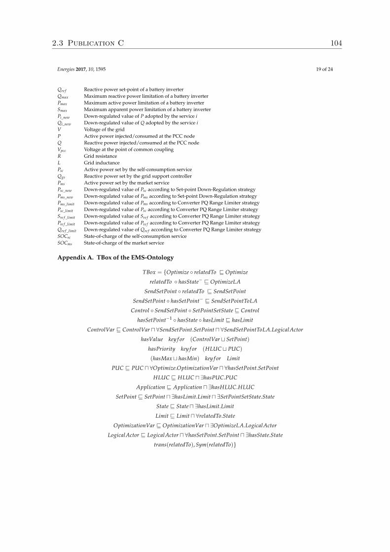
Energies 2017, 10, 1595 19 of 24
Qre f Reactive power set-point of a battery inverterQmax Maximum reactive power limitation of a battery inverterPmax Maximum active power limitation of a battery inverterSmax Maximum apparent power limitation of a battery inverterPi_new Down-regulated value of P adopted by the service iQi_new Down-regulated value of Q adopted by the service iV Voltage of the gridP Active power injected/consumed at the PCC nodeQ Reactive power injected/consumed at the PCC nodeVpcc Voltage at the point of common couplingR Grid resistanceL Grid inductancePsc Active power set by the self-consumption serviceQgs Reactive power set by the grid support controllerPms Active power set by the market servicePsc_new Down-regulated value of Psc according to Set-point Down-Regulation strategyPms_new Down-regulated value of Pms according to Set-point Down-Regulation strategyPms_limit Down-regulated value of Pms according to Converter PQ Range Limiter strategyPsc_limit Down-regulated value of Psc according to Converter PQ Range Limiter strategySre f _limit Down-regulated value of Sre f according to Converter PQ Range Limiter strategyPre f _limit Down-regulated value of Pre f according to Converter PQ Range Limiter strategyQre f _limit Down-regulated value of Qre f according to Converter PQ Range Limiter strategySOCsc State-of-charge of the self-consumption serviceSOCms State-of-charge of the market service
Appendix A. TBox of the EMS-Ontology
TBox = {Optimize ◦ relatedTo v Optimize
relatedTo ◦ hasState− v OptimizeLA
SendSetPoint ◦ relatedTo v SendSetPoint
SendSetPoint ◦ hasSetPoint− v SendSetPointToLA
Control ◦ SendSetPoint ◦ SetPointSetState v Control
hasSetPoint−1 ◦ hasState ◦ hasLimit v hasLimit
ControlVar v ControlVar u ∀SendSetPoint.SetPoint u ∀SendSetPointToLA.LogicalActor
hasValue key f or (ControlVar t SetPoint)
hasPriority key f or (HLUC t PUC)
(hasMax t hasMin) key f or Limit
PUC v PUC u ∀Optimize.OptimizationVar u ∀hasSetPoint.SetPoint
HLUC v HLUC u ∃hasPUC.PUC
Application v Application u ∃hasHLUC.HLUC
SetPoint v SetPoint u ∃hasLimit.Limit u ∃SetPointSetState.State
State v State u ∃hasLimit.Limit
Limit v Limit u ∀relatedTo.State
OptimizationVar v OptimizationVar u ∃OptimizeLA.LogicalActor
LogicalActor v LogicalActor u ∀hasSetPoint.SetPoint u ∃hasState.State
trans(relatedTo), Sym(relatedTo)}
2.3 Publication C 104
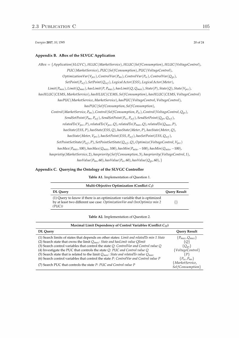
Energies 2017, 10, 1595 20 of 24
Appendix B. ABox of the SLVGC Application
ABox = {Application(SLGVC), HLUC(MarketService), HLUC(Sel f Consumption), HLUC(VoltageControl),
PUC(MarketService), PUC(Sel f Consumption), PUC(VoltageControl),
OptimizationVar(Vpcc), ControlVar(Pms), ControlVar(Psc), ControlVar(Qgs),
SetPoint(Pre f ), SetPoint(Qre f ), LogicalActor(ESS), LogicalActor(Meter),
Limit(Pmax), Limit(Qmax), hasLimit(P, Pmax), hasLimit(Q, Qmax), State(P), State(Q), State(Vpcc),
hasHLUC(CEMS, MarketService), hasHLUC(CEMS, Sel f Consumption), hasHLUC(CEMS, VoltageControl)
hasPUC(MarketService, MarketService), hasPUC(VoltageControl, VoltageControl),
hasPUC(Sel f Consumption, Sel f Consumption),
Control(MarketService, Pms), Control(Sel f Consumption, Psc), Control(VoltageControl, Qgs),
SendSetPoint(Pms, Pre f ), SendSetPoint(Psc, Pre f ), SendSetPoint(Qgs, Qre f ),
relatedTo(Vpcc, P), relatedTo(Vpcc, Q), relatedTo(Pmax, Q), relatedTo(Qmax, P),
hasState(ESS, P), hasState(ESS, Q), hasState(Meter, P), hasState(Meter, Q),
hasState(Meter, Vpcc), hasSetPoint(ESS, Pre f ), hasSetPoint(ESS, Qre f ),
SetPointSetState(Pre f , P), SetPointSetState(Qre f , Q), Optimize(VoltageControl, Vpcc)
hasMax(Pmax, 100), hasMax(Qmax, 100), hasMin(Pmin,−100), hasMin(Qmin,−100),
haspriotiy(MarketService, 2), haspriority(Sel f Consumption, 3), haspriority(VoltageControl, 1),
hasValue(Pms, 60), hasValue(Psc, 60), hasValue(Qgs, 60), }
Appendix C. Querying the Ontology of the SLVGC Controller
Table A1. Implementation of Question 1.
Multi-Objective Optimization (Conflict CI)
DL Query Query Result
(1) Query to know if there is an optimization variable that is optimizedby at least two different use case: OptimizationVar and (InvOptimize min 2(PUC))
{}
Table A2. Implementation of Question 2.
Maximal Limit Dependency of Control Variables (Conflict CI I)
DL Query Query Result
(1) Search limits of states that depends on other states: Limit and relatedTo min 1 State {Pmax, Qmax}(2) Search state that owns the limit Qmax: State and hasLimit value Qlimit {Q}(3) Search control variables that control the state Q: ControlVar and Control value Q {Qgs}(4) Investigate the PUC that controls the state Q: PUC and Control value Q {VoltageControl}(5) Search state that is related to the limit Qmax: State and relatedTo value Qmax {P}(6) Search control variables that control the state P: ControlVar and Control value P {Psc, Pms}(7) Search PUC that controls the state P: PUC and Control value P {MarketService,
Sel f Consumption}
2.3 Publication C 105
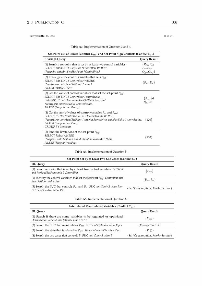
Energies 2017, 10, 1595 21 of 24
Table A3. Implementation of Question 3 and 4.
Set-Point out of Limits (Conflict CI I I) and Set-Point Sign Conflicts (Conflict CIV )
SPARQL Query Query Result
(1) Search a set-point that is set by at least two control variables:SELECT DISTINCT ?setpoint ?ControlVar WHERE{?setpoint onto:InvSendSetPoint ?ControlVar.}
{Pms, Pre fPsc, Pre fQgs, Qre f }
(2) Investigate the control variables that sets Pre f :SELECT DISTINCT ?controlvar WHERE{?controlvar onto:SendSetPoint ?value.}FILTER (?value=Pset)}
{Pms, Psc}
(3) Get the value of control variables that set the set-point Pre f :SELECT DISTINCT ?controlvar ?controlvalueWHERE { ?controlvar onto:SendSetPoint ?setpoint
?controlvar onto:hasValue ?controlvalue.FILTER (?setpoint=st:Psett)}
{Pms, 60Psc, 60}
(4) Get the sum of values of control variables Psc and Pms:SELECT (SUM(?controlvalue) as ?TotalSetpoint) WHERE{?controlvar onto:SendSetPoint ?setpoint.?controlvar onto:hasValue ?controlvalue.FILTER (?setpoint=st:Pset)}GROUP BY ?setpoint
{120}
(5) Find the limitations of the set-point Pre f :SELECT ?Max WHERE{?setpoint onto:hasLimit ?limit.?limit onto:hasMax ?Max.FILTER (?setpoint=st:Pset)}
{100}
Table A4. Implementation of Question 5.
Set-Point Set by at Least Two Use Cases (Conflict CV )
DL Query Query Result
(1) Search set-point that is set by at least two control variables: SetPointand InvSendSetPoint min 2 ControlVar {Pre f }
(2) Identify the control variables that set the SetPoint Pre f : ControlVar andSendSetPoint value Pset {Pms, Psc}
(3) Search the PUC that controls Pms and Psc: PUC and Control value Pms,PUC and Control value Psc {Sel f Consumption, MarketService}
Table A5. Implementation of Question 6.
Interrelated Manipulated Variables (Conflict CV I)
DL Query Query Result
(1) Search if there are some variables to be regulated or optimized:OptimizationVar and InvOptimize min 1 PUC {Vpcc}
(2) Search the PUC that manipulates Vpcc: PUC and Optimize value Vpcc {VoltageControl}(3) Search the state that is related to Vpcc: State and relatedTo value Vpcc {P, Q}(4) Search the use cases that controls P: PUC and Control value P {Sel f Consumption, MarketService}
2.3 Publication C 106
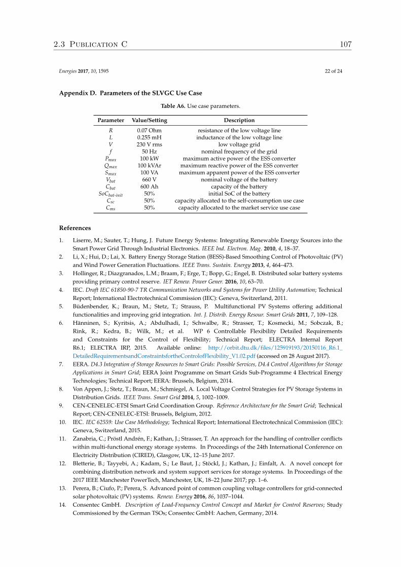
Energies 2017, 10, 1595 22 of 24
Appendix D. Parameters of the SLVGC Use Case
Table A6. Use case parameters.
Parameter Value/Setting Description
R 0.07 Ohm resistance of the low voltage lineL 0.255 mH inductance of the low voltage lineV 230 V rms low voltage gridf 50 Hz nominal frequency of the grid
Pmax 100 kW maximum active power of the ESS converterQmax 100 kVAr maximum reactive power of the ESS converterSmax 100 VA maximum apparent power of the ESS converterVbat 660 V nominal voltage of the batteryCbat 600 Ah capacity of the battery
SoCbat-init 50% initial SoC of the batteryCsc 50% capacity allocated to the self-consumption use caseCms 50% capacity allocated to the market service use case
References
1. Liserre, M.; Sauter, T.; Hung, J. Future Energy Systems: Integrating Renewable Energy Sources into theSmart Power Grid Through Industrial Electronics. IEEE Ind. Electron. Mag. 2010, 4, 18–37.
2. Li, X.; Hui, D.; Lai, X. Battery Energy Storage Station (BESS)-Based Smoothing Control of Photovoltaic (PV)and Wind Power Generation Fluctuations. IEEE Trans. Sustain. Energy 2013, 4, 464–473.
3. Hollinger, R.; Diazgranados, L.M.; Braam, F.; Erge, T.; Bopp, G.; Engel, B. Distributed solar battery systemsproviding primary control reserve. IET Renew. Power Gener. 2016, 10, 63–70.
4. IEC. Draft IEC 61850-90-7 TR Communication Networks and Systems for Power Utility Automation; TechnicalReport; International Electrotechnical Commission (IEC): Geneva, Switzerland, 2011.
5. Büdenbender, K.; Braun, M.; Stetz, T.; Strauss, P. Multifunctional PV Systems offering additionalfunctionalities and improving grid integration. Int. J. Distrib. Energy Resour. Smart Grids 2011, 7, 109–128.
6. Hänninen, S.; Kyritsis, A.; Abdulhadi, I.; Schwalbe, R.; Strasser, T.; Kosmecki, M.; Sobczak, B.;Rink, R.; Kedra, B.; Wilk, M.; et al. WP 6 Controllable Flexibility Detailed Requirementsand Constraints for the Control of Flexibility; Technical Report; ELECTRA Internal ReportR6.1; ELECTRA IRP, 2015. Available online: http://orbit.dtu.dk/files/125919193/20150116_R6.1_DetailedRequirementsandConstraintsfortheControlofFlexibility_V1.02.pdf (accessed on 28 August 2017).
7. EERA. D4.3 Integration of Storage Resources to Smart Grids: Possible Services, D4.4 Control Algorithms for StorageApplications in Smart Grid; EERA Joint Programme on Smart Grids Sub-Programme 4 Electrical EnergyTechnologies; Technical Report; EERA: Brussels, Belgium, 2014.
8. Von Appen, J.; Stetz, T.; Braun, M.; Schmiegel, A. Local Voltage Control Strategies for PV Storage Systems inDistribution Grids. IEEE Trans. Smart Grid 2014, 5, 1002–1009.
9. CEN-CENELEC-ETSI Smart Grid Coordination Group. Reference Architecture for the Smart Grid; TechnicalReport; CEN-CENELEC-ETSI: Brussels, Belgium, 2012.
10. IEC. IEC 62559: Use Case Methodology; Technical Report; International Electrotechnical Commission (IEC):Geneva, Switzerland, 2015.
11. Zanabria, C.; Pröstl Andrén, F.; Kathan, J.; Strasser, T. An approach for the handling of controller conflictswithin multi-functional energy storage systems. In Proceedings of the 24th International Conference onElectricity Distribution (CIRED), Glasgow, UK, 12–15 June 2017.
12. Bletterie, B.; Tayyebi, A.; Kadam, S.; Le Baut, J.; Stöckl, J.; Kathan, J.; Einfalt, A. A novel concept forcombining distribution network and system support services for storage systems. In Proceedings of the2017 IEEE Manchester PowerTech, Manchester, UK, 18–22 June 2017; pp. 1–6.
13. Perera, B.; Ciufo, P.; Perera, S. Advanced point of common coupling voltage controllers for grid-connectedsolar photovoltaic (PV) systems. Renew. Energy 2016, 86, 1037–1044.
14. Consentec GmbH. Description of Load-Frequency Control Concept and Market for Control Reserves; StudyCommissioned by the German TSOs; Consentec GmbH: Aachen, Germany, 2014.
2.3 Publication C 107
Energies 2017, 10, 1595 23 of 24
15. Braam, F.; Hollinger, R.; Engesser, M.L.; Müller, S.; Kohrs, R.; Wittwer, C. Peak shaving withphotovoltaic-battery systems. In Proceedings of the Innovative Smart Grid Technologies ConferenceEurope (ISGT-Europe), Istanbul, Turkey, 12–15 October 2014; pp. 1–5.
16. Riffonneau, Y.; Bacha, S.; Barruel, F.; Ploix, S. Optimal Power Flow Management for Grid Connected PVSystems With Batteries. IEEE Trans. Sustain. Energy 2011, 2, 309–320.
17. Andrén, F.; Lehfuss, F.; Strasser, T. A development and validation environment for real-timecontroller-hardware-in-the-loop experiments in Smart Grids. Int. J. Distrib. Energy Resour. Smart Grids 2013,9, 27–50.
18. Zanabria, C.; Andrén, F.P.; Kathan, J.; Strasser, T. Towards an integrated development of control applicationsfor multi-functional energy storages. In Proceedings of the IEEE 21st International Conference on EmergingTechnologies and Factory Automation (ETFA), Berlin, Germany, 6–9 September 2016; pp. 1–4.
19. Faschang, M.; Schwalbe, R.; Einfalt, A.; Mosshammer, R. Controller hardware in the loop approachessupporting rapid prototyping of smart low voltage grid control. In Proceedings of the 2014 IEEE PESInnovative Smart Grid Technologies Conference Europe (ISGT-Europe), Istanbul, Turkey, 12–15 October 2014;pp. 1–5.
20. Hitzler, P.; Krötzsch, M.; Rudolph, S. Foundations of Semantic Web Technologies; Chapman & Hall/CRC:London, UK, 2009.
21. Schachinger, D.; Kastner, W.; Gaida, S. Ontology-based abstraction layer for smart grid interaction in buildingenergy management systems. In Proceedings of the IEEE International Energy Conference (ENERGYCON),Leuven, Belgium, 4–8 April 2016; pp. 1–6.
22. Samirmi, F.D.; Tang, W.; Wu, Q. Fuzzy Ontology Reasoning for Power Transformer Fault Diagnosis.Adv. Electr. Comput. Eng. 2015, 15, 107–114.
23. Baader, F. The Description Logic Handbook: Theory, Implementation and Applications; Cambridge UniversityPress: Cambridge, UK, 2003.
24. Brambilla, M.; Cabot, J.; Wimmer, M. Model-Driven Software Engineering in Practice. Synth. Lect. Softw. Eng.2012, 1, 1–182.
25. Siegel, J. Developing in OMG’s New Model-Driven Architecture; Object Management Group (OMG): Needham,MA, USA, 2001.
26. Dänekas, C.; Neureiter, C.; Rohjans, S.; Uslar, M.; Engel, D. Towards a model-driven-architecture process forsmart grid projects. In Digital Enterprise Design & Management; Springer: Warsaw, Poland, 2014; pp. 47–58.
27. Andrén, F.; Strasser, T.; Kastner, W. Engineering Smart Grids: Applying Model-Driven Development fromUse Case Design to Deployment. Energies 2017, 10, 374.
28. Working Group Sustainable Processes (SG-CG/SP). CEN-CENELEC-ETSI Smart Grid CoordinationGroup—Sustainable Processes; Technical Report; CEN-CENELEC-ETSI: Brussels, Belgium, 2012.
29. Kalibatiene, D.; Vasilecas, O. Survey on Ontology Languages. In Perspectives in Business Informatics Research;Grabis, J., Kirikova, M., Eds.; Springer: Berlin/Heidelberg, Germany, 2011; Volume 90, pp. 124–141.
30. Tayyebi, A.; Bletterie, B.; Kupzog, F. Primary Control Reserve and Self-Sufficiency Provision withCentral Battery Energy Storage System. In Proceedings of the NEIS Conference, Hamburg, Germany,21–22 September 2017; in press.
31. Hua, Y.; Zander, S.; Bordignon, M.; Hein, B. From AutomationML to ROS: A model-driven approach forsoftware engineering of industrial robotics using ontological reasoning. In Proceedings of the 2016 IEEE21st International Conference on Emerging Technologies and Factory Automation (ETFA), Berlin, Germany,6–9 September 2016; pp. 1–8.
32. Apache Jena. Ontology API, 2012. Available online: https://jena.apache.org/documentation/ontology/(accessed on 12 March 2017).
33. World Wide Web Consortium. SPARQL 1.1 Query Language, 2008. Available online: https://www.w3.org/TR/sparql11-query/ (accessed on 11 February 2017).
34. Tayyebi, A. Modelling and Simulation of a Multifunctional PV Electrochemical Storage System.Master’s Thesis, University of Oviedo, Oviedo, Spain, 2016.
35. Yazdani, A.; Iravani, R. Voltage-Sourced Converters in Power Systems: Modeling, Control, and Applications;John Wiley & Sons: Hoboken, NJ, USA, 2010.
2.3 Publication C 108
Energies 2017, 10, 1595 24 of 24
36. Bredillet, P.; Lambert, E.; Schultz, E. CIM, 61850, COSEM standards used in a model driven integrationapproach to build the smart grid service oriented architecture. In Proceedings of the First IEEE InternationalConference on Smart Grid Communications (SmartGridComm), Gaithersburg, MD, USA, 4–6 October 2010;pp. 467–471.
37. Heussen, K.; Gehrke, O.; Niemann, H. On early conflict identification by requirements modeling of energysystem control structures. In Proceedings of the IEEE 20th Conference on Emerging Technologies & FactoryAutomation (ETFA), Luxembourg City, Luxembourg, 8–11 September 2015; pp. 1–8.
38. Uslar, M.; Heussen, K. Towards modeling future energy infrastructures—The ELECTRA system engineeringapproach. In Proceedings of the PES Innovative Smart Grid Technologies Conference Europe (ISGT-Europe),Ljubljana, Slovenia, 9–12 October 2016; pp. 1–6.
c© 2017 by the authors. Licensee MDPI, Basel, Switzerland. This article is an open accessarticle distributed under the terms and conditions of the Creative Commons Attribution(CC BY) license (http://creativecommons.org/licenses/by/4.0/).
2.3 Publication C 109
Bibliography
[1] EERA Joint Programme on Smart Grids-Sub-Programme 4-Electrical EnergyTechnologies. Technical Report D4.3 Integration of Storage Resources to SmartGrids: Possible Services, D4.4 Control Algorithms for Storage Applications inSmart Grid., Brussels, Belgium, April 2014.
[2] X. Liu, A.s Aichhorn, L. Liu, and H. Li. Coordinated control of distributed energystorage system with tap changer transformers for voltage rise mitigation underhigh photovoltaic penetration. IEEE Transactions on Smart Grid, 3(2):897–906,June 2012.
[3] SMB Smart Grid Strategic Group (SG3). IEC Smart Grid StandardizationRoadmap. Geneva, Switzerland, 2013.
[4] C. Tornelli, L. Radaelli, E. Rikos, and M. Uslar. WP 4 Fully Interoperable Sys-tems. Deliverable R4.1: Description of the methodology for the detailed functionalspecification of the ELECTRA solutions. IST project, 2015.
[5] C. Dänekas, C. Neureiter, S. Rohjans, M. Uslar, and D. Engel. Towards a model-driven-architecture process for smart grid projects. In Digital Enterprise Design& Management, pages 47–58. Springer, 2014.
[6] F. Andrén, T. Strasser, and W. Kastner. Engineering Smart Grids: Apply-ing Model-Driven Development from Use Case Design to Deployment. Energies,10(3):374, March 2017.
[7] F. Andrén, S. Henein, and M. Stifter. Development and validation of a coordinatedvoltage controller using real-time simulation. In IECON 2011 - 37th Annual Con-ference of the IEEE Industrial Electronics Society, pages 3713–3718, Melbourne,Australia, November 2011.
[8] T. Strasser, F. Pröstl Andrén, G. Lauss, R. Bründlinger, H. Brunner, C. Moyo,and others. Towards holistic power distribution system validation and testing—anoverview and discussion of different possibilities. e & i Elektrotechnik und Infor-mationstechnik, 134(1):71–77, February 2017.
Bibliography 111
[9] A. Kossiakoff, W. N. Sweet, S. J. Seymour, and S. M. Biemer. Systems engineeringprinciples and practice, volume 83. John Wiley & Sons, 2011.
[10] H. H. Abdeltawab and Y. A. I Mohamed. Market-oriented energy managementof a hybrid wind-battery energy storage system via model predictive control withconstraint optimizer. IEEE Transactions on Industrial Electronics, 62(11):6658–6670, November 2015.
[11] S. Rohjans, S. Lehnhoff, S. Schütte, F. Andrén, and T. Strasser. Requirementsfor smart grid simulation tools. In 2014 IEEE 23rd International Symposium onIndustrial Electronics (ISIE), pages 1730–1736, Istambul, Turkey, June 2014.
[12] C. Zanabria, F. Pröstl Andrén, and T. I. Strasser. Comparing specification anddesign approaches for power systems applications. In 2018 IEEE PES TransmissionDistribution Conference and Exhibition - Latin America (T&D-LA), pages 1–5,Lima, Peru, September 2018.
[13] International Electrotechnical Commission (IEC). IEC 62559-2 Use CaseMethodology-Part2: Definition of the templates for use cases, actor list and re-quirement list. Geneva, Switzerland, 2015.
[14] T. Weilkiens. Systems Engineering with SysML/UML: Modeling, Analysis, Design.Elsevier, August 2011.
[15] R. Lewis. Modelling Control Systems Using IEC 61499: Applying Function Blocksto Distributed Systems. IET, 2001.
[16] P. Hitzler, M. Krotzsch, and S. Rudolph. Foundations Of Semantic Web Technolo-gies. CRC press, 2009.
[17] R. Santodomingo, S. Rohjans, M. Uslar, J.A. Rodríguez-Mondéjar, and M.A. Sanz-Bobi. Ontology matching system for future energy smart grids. Engineering Ap-plications of Artificial Intelligence, 32:242–257, June 2014.
[18] V. Dubinin, V. Vyatkin, C. Yang, and C. Pang. Automatic generation of au-tomation applications based on ontology transformations. In Proceedings of the2014 IEEE Emerging Technology and Factory Automation (ETFA), pages 1–4,Barcelona, Spain, 2014. IEEE.
[19] M. Brambilla, J. Cabot, and M. Wimmer. Model-Driven Software Engineering inPractice. Synthesis Lectures on Software Engineering, 1(1):1–182, September 2012.
Bibliography 112
[20] F. Andrén, T. Strasser, and W. Kastner. Model-Driven Engineering applied toSmart Grid Automation using IEC 61850 and IEC 61499. In Power Systems Com-putation Conference, pages 1–7, Wroclaw, Poland, 2014.
[21] D. Schachinger, W. Kastner, and S. Gaida. Ontology-based abstraction layer forsmart grid interaction in building energy management systems. In 2016 IEEEInternational Energy Conference (ENERGYCON), pages 1–6, April 2016.
[22] F. D. Samirmi, W. Tang, and Q. Wu. Fuzzy Ontology Reasoning for PowerTransformer Fault Diagnosis. Advances in Electrical and Computer Engineering,15(4):107–114, 2015.
[23] B. K. Perera, P. Ciufo, and S. Perera. Point of common coupling (PCC) voltagecontrol of a grid-connected solar photovoltaic (PV) system. In Industrial Electron-ics Society, IECON 2013-39th Annual Conference of the IEEE, pages 7475–7480,Vienna, Austria, 2013. IEEE.
[24] J. von Appen, T. Stetz, M. Braun, and A. Schmiegel. Local Voltage ControlStrategies for PV Storage Systems in Distribution Grids. IEEE Transactions onSmart Grid, 5(2):1002–1009, March 2014.
[25] Y. Riffonneau, S. Bacha, F. Barruel, and S. Ploix. Optimal Power Flow Man-agement for Grid Connected PV Systems With Batteries. IEEE Transactions onSustainable Energy, 2(3):309–320, July 2011.
[26] A. Tayyebi, B. Bletterie, and F. Kupzog. Primary Control Reserve and Self-Sufficiency Provision with Central Battery Energy Storage Systens. In Proceedingsof the NEIS Conference, pages 21–22, Hamburg, Germany, 2017.
[27] International Electrotechnical Commission. IEC/TR 61850-90-7—CommunicationNetworks and Systems for Power Utility Automation—Part 90-7: Object Modelsfor Power Converters in Distributed Energy Resources (DER) Systems. 2013.
[28] F. Baader. The Description Logic Handbook: Theory, Implementation and Appli-cations. Cambridge university press, 2003.
[29] Working Group Sustainable Processes (SG-CG/SP). CEN-CENELEC-ETSI SmartGrid Coordination Group – Sustainable Processes. Technical report, CEN-CENELEC-ETSI, Brussels, Belgium, November 2012.
[30] I. Horrocks, O. Kutz, and U. Sattler. The Even More Irresistible SROIQ. Kr,6:57–67, 2006.

Bibliography 113
[31] H. Happel and S. Seedorf. Applications of Ontologies in Software Engineering.Proc. of Workshop on Sematic Web Enabled Software Engineering"(SWESE) onthe ISWC, pages 5–9, 2006.
[32] D. M. Powers. Evaluation: From precision, recall and F-measure to ROC, informed-ness, markedness and correlation. Bioinfo Publications, 2(1):pp–37–63, 2011.

Claudia ZanabriaSingle, French, 32 years old – Währinger gürtel 130/18 1090 Vienna, Austria
Æ +43 66066 88993 • Q [email protected]
Research engineer with experience in the conception of innovative ICT solutions that guarantee the flexibilityand interoperability of electricity distribution networks. Strong technical competences in modeling, designing,implementing and validating power system networks. Solid knowledge of smart grid standards and control strategiesfor the power system domain. Significant experience in field work.
Professional experience
+PhD Candidate ViennaAustrian Institute of Technology-Center for Energy October 2014–December 2018Realization of methodologies for a rapid and massive implementation of energy management systems focused onenergy storage systems integration. Implementation of control applications under SGAM, IEC 61850 and CIMstandards. Use of model-driven-engineering techniques to automate the control application development process.
+Automation and Control Engineer for Intelligent Building Systems Île de FranceAssystem E&OS-BU Automation September 2011– September 2014Realization of a full ICT solution for the control and supervision of Building Management Systems. Conception ofcommunication and component architectures. Design and implementation of control strategies. Programming ofcontrollers under the standard IEC 61131-3. Conception and realization of SCADA and databases. Planning of thecommunication network to host intelligent electronic devices. Modeling and simulation of the process under study.Controller-Hardware-in-the-loop validation. Supervision of fieldwork to achieve a full deployment of ICT solutions.
+Control Engineer for the Automation of the A14x86 Motorway in France Île de FranceActemium-Paris (Groupe Vinci Energie) February 2011–July 2011Design and implementation of SCADA systems and PLC programs (Siemens S7-400) for a full control and supervisionof the A14x86 motorway. Conduct of FAT and SAT tests. Field work for a massive integration of controllers.
+Junior Research for the Modeling of Electric Distribution Networks GrenobleGIE-IDEA: Group conformed by EDF, Grenoble INP and Schneider Electric January 2010–August 2010Modeling of failures in electricity distribution networks under the IEC 61850 power automation approach.
Education
+Vienna University of Technology ViennaPhD at Institute of Mechanics and Mechatronics , in process 2014–2018
+ENSE3-Grenoble INP GrenobleDiplôme d’Ingénieur in Automatic Control, Systems and Information Technology 2009–2011
+National University of Engineering LimaBachelor of Science in Electronics Engineering 2003–2008
Technical and Personal skills+ Programming Languages: Proficient in: Matlab/Simulink, Java, C#, C++, Assembly, VBA, SQL.+ Industry Software Skills: PcVue (SCADA), LabVIEW, Step 7 (PLC), CodeSys, MPLAB (microcontrollers).+ General Business Skills: Good presentation skills. Can write structured reports and journal papers.+ Languages: Advanced level in Spanish, French, English and Intermediate level in German.
Curriculum Vitae
List of Scientific Publications
Peer-reviewed International Journal PapersC. Zanabria, F. Pröstl Andrén, and T. I. Strasser.An Adaptable Engineering Support Framework for Multi-Functional EnergyStorage System Applications.Sustainability, vol. 10, no. 11, 28 pages, 2018.
C. Zanabria, F. Pröstl Andrén, J. Kathan, and T. I. Strasser.Rapid Prototyping of Multi-Functional Battery Energy Storage System Ap-plications.Applied Sciences, vol. 8, no. 8, 32 pages, 2018.
C. Zanabria, A. Tayyebi, F. Pröstl Andrén, J. Kathan, and T. Strasser.Engineering Support for Handling Controller Conflicts in Energy StorageSystems Applications.Energies, vol. 10, no. 10, 24 pages, 2017.
C. Zanabria, F. Pröstl Andrén, J. Kathan, and T. Strasser.Approach for Handling Controller Conflicts within Multi-Functional EnergyStorage Systems.CIRED - Open Access Proceedings Journal, vol. 2017, no. 1, pp. 1575-1578, 2017.
Peer-reviewed International Conference PapersC. Zanabria, F. Pröstl Andrén, and T. I. Strasser.Comparing Specification and Design Approaches for Power Systems Appli-cations.2018 IEEE PES Transmission & Distribution Conference and Exhibition-Latin Amer-ica (T&D-LA), September 18-21, Lima, Peru, 2018.
C. Zanabria, F. Pröstl Andrén, J. Kathan, and T. Strasser.An Approach for the Handling of Controller Conflicts within Multi-FunctionalEnergy Storage Systems.24th International Conference on Electricity Distribution (CIRED), June 12-15, Glas-gow, UK, 2017.
Bibliography 116
C. Zanabria, F. Pröstl Andrén, J. Kathan, and T. Strasser.Towards an Integrated Development of Control Applications for Multi-FunctionalEnergy Storages.21th IEEE International Conference on Emerging Technologies and Factory Automa-tion (ETFA’2016), September 6-9, Berlin, Germany, 2016.
C. Zanabria, F. Andrén, F. Leimgruber, R. Bründlinger, and T. Strasser.A Low Cost Open Source-based IEC 61850/61499 Automation Platform forDistributed Energy Resources.IEEE PowerTech Eindhoven 2015, June 29 - July 2, Eindhoven, The Netherlands, 2015.
Poster Presentations at International ConferencesC. Zanabria, T. Strasser, F. Andrén, J. Kathan, and S. Jakubek.Towards a Framework for the Development of Multi-Functional ESS ControlApplications.7th Advanced Doctoral Conference on Computing, Electrical and Industrial Systems,DoCEIS 2016, April 11-13, Caparica - Lisbon, Portugal, 2016.
C. Zanabria, T. Strasser, F. Andrén, and S. Lehnhoff.Rapid Prototyping of Control Applications for Multi-Functional StorageSystems.4th D-A-CH Conference Energieinformatik 2015, November 12-13, Karlsruhe, Ger-many, 2015.