Embed Size (px)
Citation preview
Alubehä lter / Behä lterzubehö rAl-Reservoirs / Accessories
2www.Hydraulik.vc
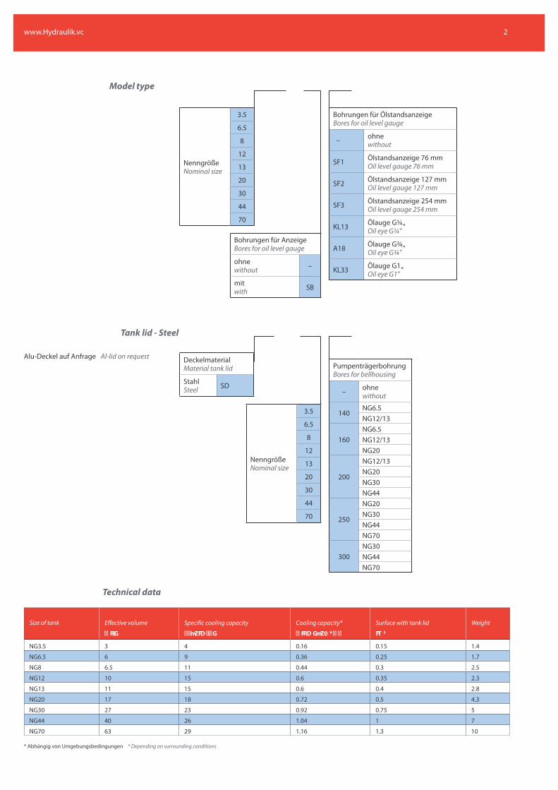
Model type
Bohrungen für AnzeigeBores for oil level gauge
ohnewithout –
mitwith SB
NenngrößeNominal size
3.5
6.5
8
12
13
20
30
44
70
Bohrungen für ÖlstandsanzeigeBores for oil level gauge
– ohnewithout
SF1 Ölstandsanzeige 76 mmOil level gauge 76 mm
SF2 Ölstandsanzeige 127 mmOil level gauge 127 mm
SF3 Ölstandsanzeige 254 mmOil level gauge 254 mm
KL13 Ölauge G¼ "Oil eye G¼ "
A18 Ölauge G¾ "Oil eye G¾ "
KL33 Ölauge G1"Oil eye G1"
Tank lid - Steel
Alu-Deckel auf Anfrage Al-lid on request
NenngrößeNominal size
3.5
6.5
8
12
13
20
30
44
70
DeckelmaterialMaterial tank lid
StahlSteel SD
PumpenträgerbohrungBores for bellhousing
– ohnewithout
140NG6.5NG12/13
160NG6.5NG12/13NG20
200
NG12/13NG20NG30NG44
250
NG20NG30NG44NG70
300NG30NG44NG70
Technical data
* Abhängig von Umgebungsbedingungen * Depending on surrounding conditions
Size of tank Effective volume Specific cooling capacity Cooling capacity* Surface with tank lid Weight2
NG3.5 3 4 0.16 0.15 1.4
NG6.5 6 9 0.36 0.25 1.7
NG8 6.5 11 0.44 0.3 2.5
NG12 10 15 0.6 0.35 2.3
NG13 11 15 0.6 0.4 2.8
NG20 17 18 0.72 0.5 4.3
NG30 27 23 0.92 0.75 5
NG44 40 26 1.04 1 7
NG70 63 29 1.16 1.3 10
3
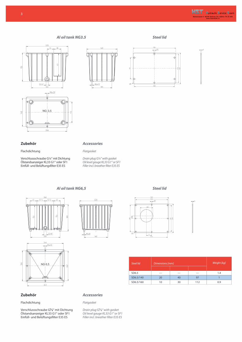
Al oil tank NG3.5 Steel lid
Zubehö r
Flachdichtung
Verschlussschraube G¼ “ mit DichtungÖlstandsanzeiger KL33 G1“ oder SF1Einfüll- und Belüftungsfilter E35 ES
Accessories
Flatgasket
Drain plug G¼ “ with gasketOil level gauge KL33 G1“ or SF1Filler incl. breather filter E35 ES
Al oil tank NG6,5 Steel lid
Zubehö r
Flachdichtung
Verschlussschraube G38“ mit Dichtung
Ölstandsanzeiger KL33 G1“ oder SF1Einfüll- und Belüftungsfilter E35 ES
Steel lid Dimensions [mm] Weight [kg]
SD6.5 — — — 1.4
SD6.5/140 20 40 97 1
SD6.5/160 10 30 112 0.9
Accessories
Flatgasket
Drain plug G38“ with gasket
Oil level gauge KL33 G1“ or SF1Filler incl. breather filter E35 ES
4
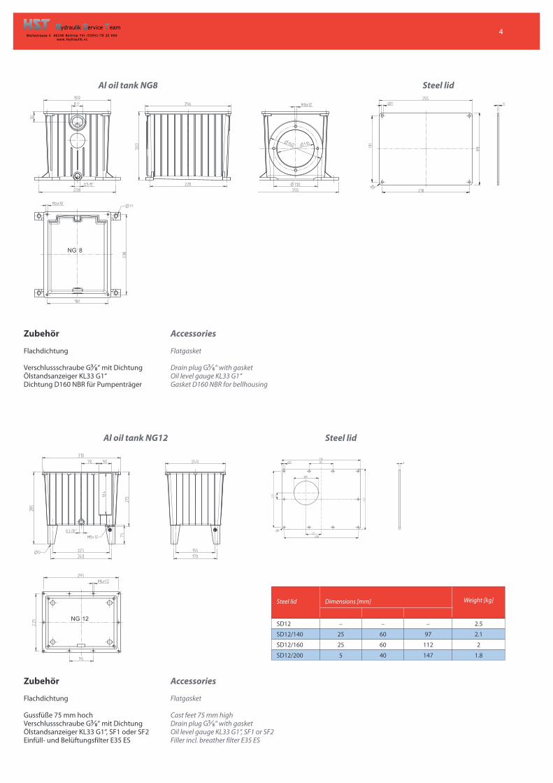
Al oil tank NG8
Al oil tank NG12 Steel lid
Zubehö r
Flachdichtung
Gussfüße 75 mm hochVerschlussschraube G3
8“ mit DichtungÖlstandsanzeiger KL33 G1“, SF1 oder SF2Einfüll- und Belüftungsfilter E35 ES
Accessories
Flatgasket
Cast feet 75 mm highDrain plug G3
8“ with gasketOil level gauge KL33 G1“, SF1 or SF2Filler incl. breather filter E35 ES
Steel lid Dimensions [mm] Weight [kg]
SD12 – – – 2.5
SD12/140 25 60 97 2.1
SD12/160 25 60 112 2
SD12/200 5 40 147 1.8
Steel lid
Zubehö r
Flachdichtung
Verschlussschraube G38“ mit Dichtung
Ölstandsanzeiger KL33 G1“Dichtung D160 NBR für Pumpenträger
Accessories
Flatgasket
Drain plug G38“ with gasket
Oil level gauge KL33 G1“Gasket D160 NBR for bellhousing
5
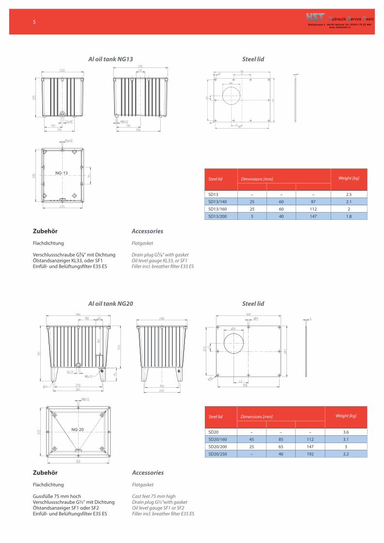
Al oil tank NG13 Steel lid
Zubehö r
Flachdichtung
Verschlussschraube G38" mit Dichtung
Ölstandsanzeiger KL33, oder SF1Einfüll- und Belüftungsfilter E35 ES
Accessories
Flatgasket
Drain plug G38" with gasket
Oil level gauge KL33, or SF1Filler incl. breather filter E35 ES
Al oil tank NG20 Steel lid
Zubehö r
Flachdichtung
Gussfüße 75 mm hochVerschlussschraube G½ " mit DichtungÖlstandsanzeiger SF1 oder SF2Einfüll- und Belüftungsfilter E35 ES
Accessories
Flatgasket
Cast feet 75 mm highDrain plug G½ "with gasketOil level gauge SF1 or SF2Filler incl. breather filter E35 ES
Steel lid Dimensions [mm] Weight [kg]
SD13 – – – 2.5
SD13/140 25 60 97 2.1
SD13/160 25 60 112 2
SD13/200 5 40 147 1.8
Steel lid Dimensions [mm] Weight [kg]
SD20 – – – 3.6
SD20/160 45 85 112 3.1
SD20/200 25 65 147 3
SD20/250 – 40 192 2.2
6
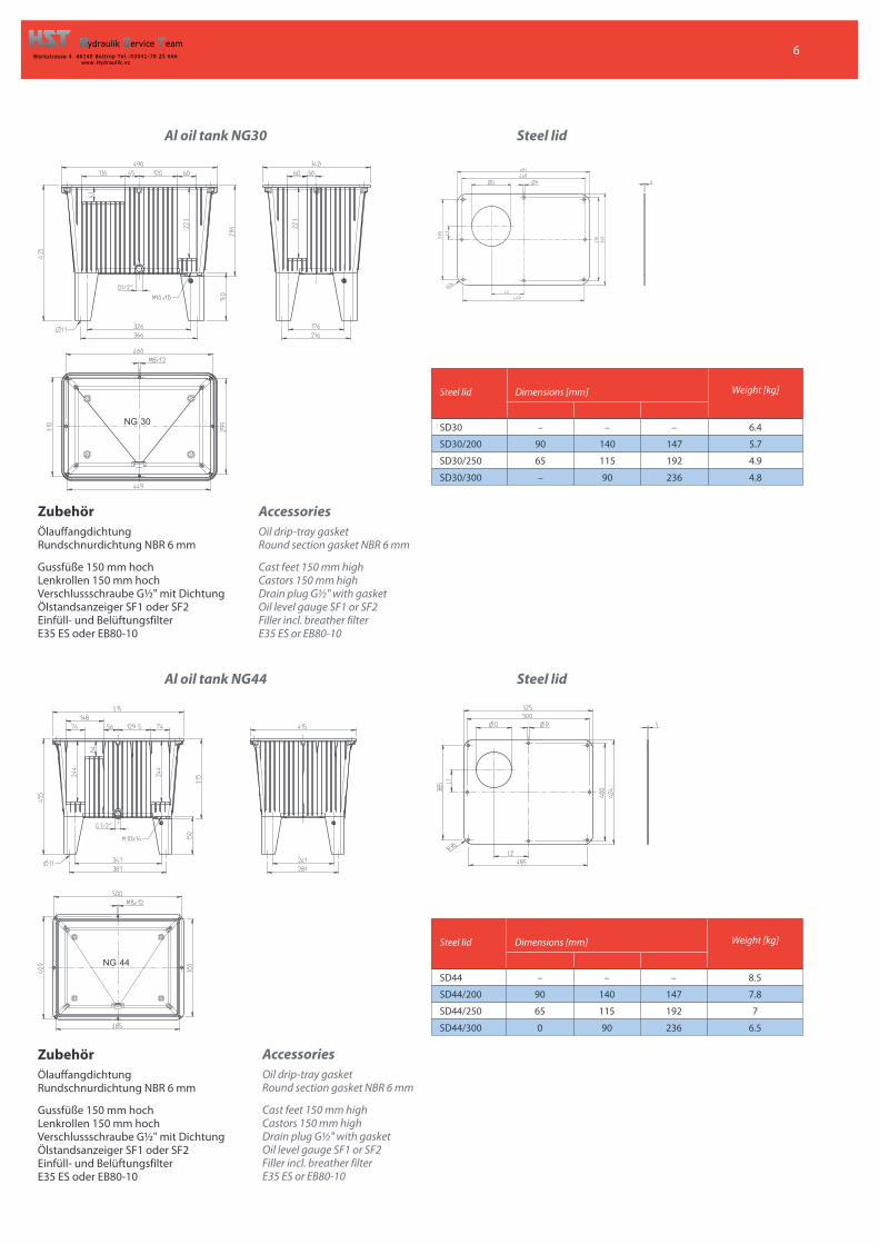
Al oil tank NG30 Steel lid
Al oil tank NG44 Steel lid
Zubehö rÖlauffangdichtungRundschnurdichtung NBR 6 mm
Gussfüße 150 mm hochLenkrollen 150 mm hochVerschlussschraube G½ " mit DichtungÖlstandsanzeiger SF1 oder SF2Einfüll- und BelüftungsfilterE35 ES oder EB80-10
Accessories
Oil drip-tray gasketRound section gasket NBR 6 mm
Cast feet 150 mm highCastors 150 mm highDrain plug G½ " with gasketOil level gauge SF1 or SF2Filler incl. breather filterE35 ES or EB80-10
Steel lid Dimensions [mm] Weight [kg]
SD30 – – – 6.4
SD30/200 90 140 147 5.7
SD30/250 65 115 192 4.9
SD30/300 – 90 236 4.8
Steel lid Dimensions [mm] Weight [kg]
SD44 – – – 8.5
SD44/200 90 140 147 7.8
SD44/250 65 115 192 7
SD44/300 0 90 236 6.5
7
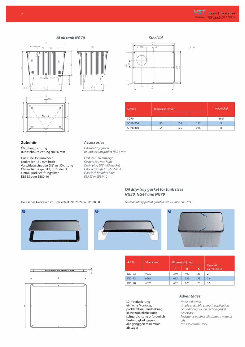
Al oil tank NG70 Steel lid
Zubehö rÖlauffangdichtungRundschnurdichtung NBR 6 mm
Gussfüße 150 mm hochLenkrollen 150 mm hochVerschlussschraube G½ " mit DichtungÖlstandsanzeiger SF1, SF2 oder SF3Einfüll- und BelüftungsfilterE35 ES oder EB80-10
Accessories
Oil drip-tray gasketRound section gasket NBR 6 mm
Cast feet 150 mm highCastors 150 mm highDrain plug G½ " with gasketOil level gauge SF1, SF2 or SF3Filler incl. breather filterE35 ES or EB80-10
Deutsches Gebrauchsmuster erteilt: Nr. 20 2006 001 703.8
Oil drip-tray gasket for tank sizes
NG30, NG44 and NG70
German utility patent granted: No 20 2006 001 703.8
Lärmreduzierung einfache Montage,problemlose Handhabung keine zusätzliche Rund-schnurdichtung erforderlich Beständigkeit gegenalle gängigen Mineralöle ab Lager
Art. No.: Oil tank size Dimensions [mm]Theoreticoil volume [l]A B C
DI0173 NG30 349 499 23 2.1
DI0172 NG44 432 533 23 2.6
DI0170 NG70 482 623 23 3.5
Steel lid Dimensions [mm] Weight [kg]
SD70 – – – 10.5
SD70/250 80 150 192 9
SD70/300 55 125 236 8
Advantages:
Noise reduction simple assembly, smooth application no additional round section gasketnecessary Resistance against all common mineraloils available from stock
1 2 3
8
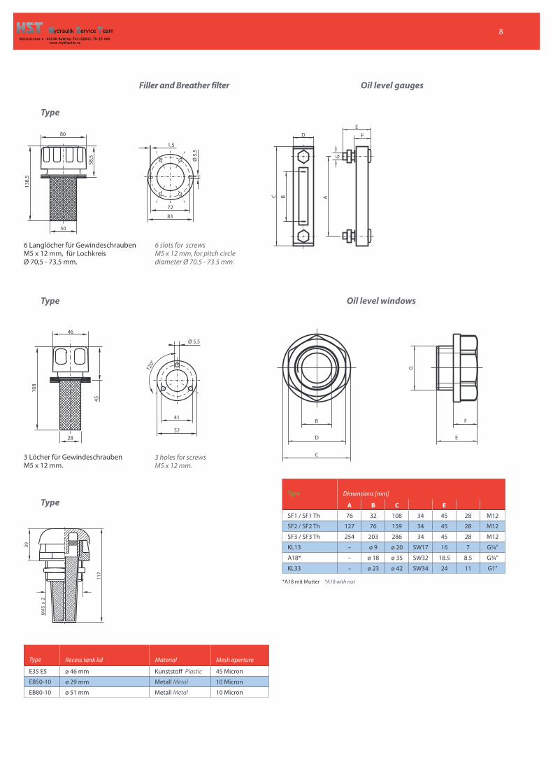
Filler and Breather filter Oil level gauges
Type
6 Langlöcher für GewindeschraubenM5 x 12 mm, für LochkreisØ 70,5 - 73,5 mm.
3 Löcher für GewindeschraubenM5 x 12 mm.
Type
80
138,
5
58,5
50
1,5
Ø 5,
5
72
83
C B A
G
DE
F
B
D
C
E
F
G
39
117
2x
M45
Type
*A18 mit Mutter *A18 with nut
Type Dimensions [mm]
A B C E
SF1 / SF1 Th 76 32 108 34 45 28 M12
SF2 / SF2 Th 127 76 159 34 45 28 M12
SF3 / SF3 Th 254 203 286 34 45 28 M12
KL13 – ø 9 ø 20 SW17 16 7 G¼ "
A18* – ø 18 ø 35 SW32 18.5 8.5 G¾ "
KL33 – ø 23 ø 42 SW34 24 11 G1"
Type Recess tank lid Material Mesh aperture
E35 ES ø 46 mm Kunststoff Plastic 45 Micron
EB50-10 ø 29 mm Metall Metal 10 Micron
EB80-10 ø 51 mm Metall Metal 10 Micron
6 slots for screwsM5 x 12 mm, for pitch circlediameter Ø 70.5 - 73.5 mm.
Oil level windows
3 holes for screwsM5 x 12 mm.
46
45
108
120°
41
5228
Ø 5,5
9
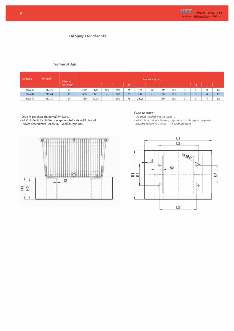
Oil Sumps for al-tanks
Technical data
Oil sump For TankOil sumpvolume [l]
Dimensions [mm]
B2 t2 z
BWA 30 NG 30 33 550 326 300 400 75 176 150 160 153 3 5 8 12
BWA 44 NG 44 45 600 341 – 500 75 241 – 160 153 3 5 4 12
BWA 70 NG 70 64 730 422,5 – 580 75 282,5 – 160 153 3 5 4 12
- Öldicht geschweißt, gemäß WHG19.- WHG19-Zertifikat & Stempel gegen Aufpreis auf Anfrage!- Pulver beschichtet RAL 9006— Weißaluminium
Please note:- Oil-tight welded, acc. to WHG19- WHG19- certificate & stamp against extra charge on request!- powder coated RAL 9006— white aluminium
10
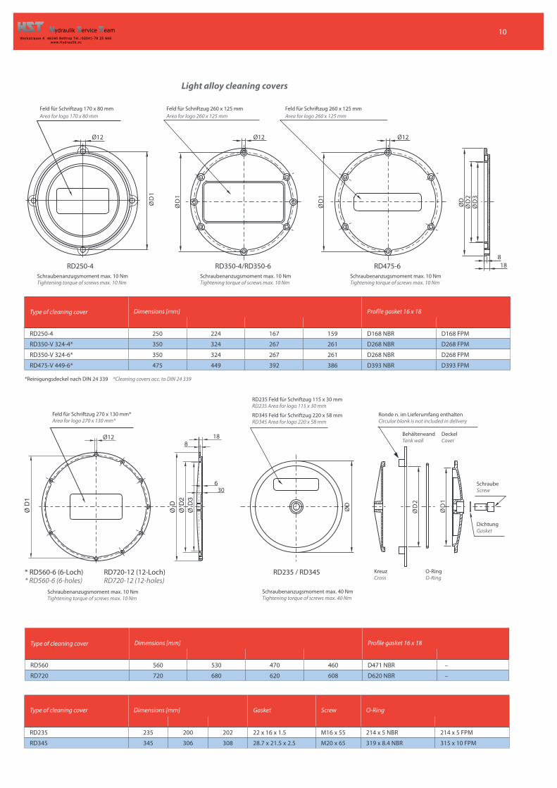
Light alloy cleaning covers
188
Ø D
3Ø
D2
Ø D
Ø 12
Ø D
1
Ø D
1
Ø 12Ø 12
ØD
1
Feld für Schriftzug 260 x 125 mmArea for logo 260 x 125 mm
Feld für Schriftzug 260 x 125 mmArea for logo 260 x 125 mm
*Reinigungsdeckel nach DIN 24 339 *Cleaning covers acc. to DIN 24 339
Ø D
1
Ø D
2
Ø D
Ø 12 188
630
Feld für Schriftzug 270 x 130 mm*Area for logo 270 x 130 mm*
RD235 Feld für Schriftzug 115 x 30 mmRD235 Area for logo 115 x 30 mm
RD345 Feld für Schriftzug 220 x 58 mmRD345 Area for logo 220 x 58 mm
RD250-4 RD350-4/RD350-6 RD475-6
BehälterwandTank wall
DeckelCover
SchraubeScrew
DichtungGasket
KreuzCross
O-RingO-Ring
* RD560-6 (6-Loch)* RD560-6 (6-holes)
RD720-12 (12-Loch)RD720-12 (12-holes)
RD235 / RD345
Schraubenanzugsmoment max. 40 NmTightening torque of screws max. 40 Nm
Type of cleaning cover Dimensions [mm] Profile gasket 16 x 18
RD250-4 250 224 167 159 D168 NBR D168 FPM
RD350-V 324-4* 350 324 267 261 D268 NBR D268 FPM
RD350-V 324-6* 350 324 267 261 D268 NBR D268 FPM
RD475-V 449-6* 475 449 392 386 D393 NBR D393 FPM
Type of cleaning cover Dimensions [mm] Gasket Screw O-Ring
RD235 235 200 202 22 x 16 x 1.5 M16 x 55 214 x 5 NBR 214 x 5 FPM
RD345 345 306 308 28.7 x 21.5 x 2.5 M20 x 65 319 x 8.4 NBR 315 x 10 FPM
Type of cleaning cover Dimensions [mm] Profile gasket 16 x 18
RD560 560 530 470 460 D471 NBR –
RD720 720 680 620 608 D620 NBR –
Ronde n. im Lieferumfang enthaltenCircular blank is not included in delivery
Schraubenanzugsmoment max. 10 NmTightening torque of screws max. 10 Nm
Schraubenanzugsmoment max. 10 NmTightening torque of screws max. 10 Nm
Schraubenanzugsmoment max. 10 NmTightening torque of screws max. 10 Nm
Schraubenanzugsmoment max. 10 NmTightening torque of screws max. 10 Nm
Feld für Schriftzug 170 x 80 mmArea for logo 170 x 80 mm
11
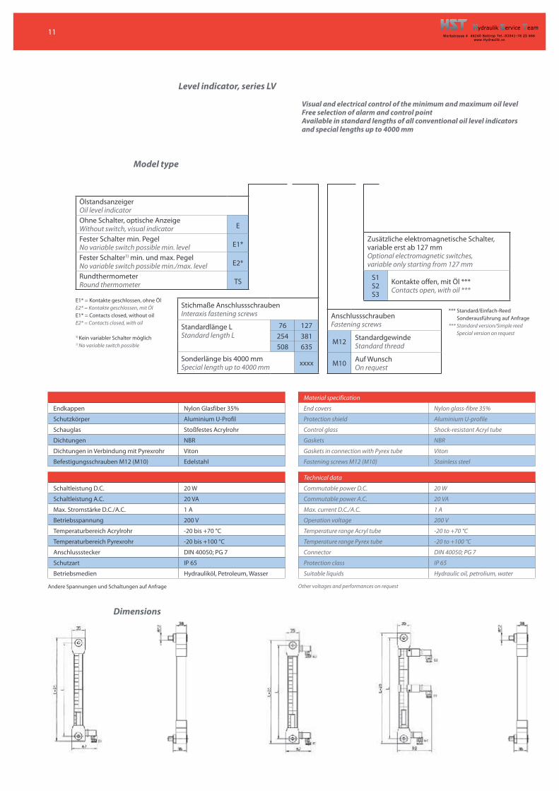
Level indicator, series LV
ÖlstandsanzeigerOil level indicatorOhne Schalter, optische AnzeigeWithout switch, visual indicator E
Fester Schalter min. PegelNo variable switch possible min. level E1*
Fester Schalter1) min. und max. PegelNo variable switch possible min./max. level E2*
RundthermometerRound thermometer TS
Stichmaße AnschlussschraubenInteraxis fastening screws
Standardlänge LStandard length L
76 127254 381508 635
Sonderlänge bis 4000 mmSpecial length up to 4000 mm xxxx
AnschlussschraubenFastening screws
M12 StandardgewindeStandard thread
M10 Auf WunschOn request
Zusätzliche elektromagnetische Schalter,variable erst ab 127 mmOptional electromagnetic switches,variable only starting from 127 mm
S1S2S3
Kontakte offen, mit Öl ***Contacts open, with oil ***
*** Standard/Einfach-ReedSonderausführung auf Anfrage
*** Standard version/Simple reedSpecial version on request
E1* = Kontakte geschlossen, ohne ÖlE2* = Kontakte geschlossen, mit ÖlE1* = Contacts closed, without oilE2* = Contacts closed, with oil
1) Kein variabler Schalter möglich1) No variable switch possible
Andere Spannungen und Schaltungen auf Anfrage
Dimensions
Visual and electrical control of the minimum and maximum oil level
Free selection of alarm and control point
Available in standard lengths of all conventional oil level indicators
and special lengths up to 4000 mm
Material specification
Endkappen Nylon Glasfiber 35% End covers Nylon glass-fibre 35%
Schutzkörper Aluminium U-Profil Protection shield Aluminium U-profile
Schauglas Stoßfestes Acrylrohr Control glass Shock-resistant Acryl tube
Dichtungen NBR Gaskets NBR
Dichtungen in Verbindung mit Pyrexrohr Viton Gaskets in connection with Pyrex tube Viton
Befestigungsschrauben M12 (M10) Edelstahl Fastening screws M12 (M10) Stainless steel
Technical data
Schaltleistung D.C. 20 W Commutable power D.C. 20 W
Schaltleistung A.C. 20 VA Commutable power A.C. 20 VA
Max. Stromstärke D.C./A.C. 1 A Max. current D.C./A.C. 1 A
Betriebsspannung 200 V Operation voltage 200 V
Temperaturbereich Acrylrohr -20 bis +70 °C Temperature range Acryl tube -20 to +70 °C
Temperaturbereich Pyrexrohr -20 bis +100 °C Temperature range Pyrex tube -20 to +100 °C
Anschlussstecker DIN 40050; PG 7 Connector DIN 40050; PG 7
Schutzart IP 65 Protection class IP 65
Betriebsmedien Hydrauliköl, Petroleum, Wasser Suitable liquids Hydraulic oil, petrolium, water
Model type
Other voltages and performances on request
12
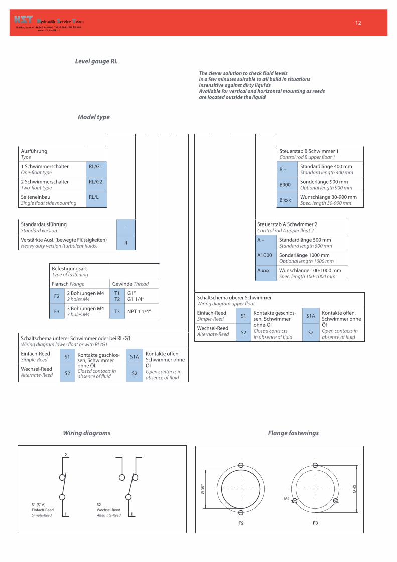
Level gauge RL
AusführungType
1 SchwimmerschalterOne-float type
RL/G1
2 SchwimmerschalterTwo-float type
RL/G2
SeiteneinbauSingle float side mounting
RL/L
StandardausführungStandard version –
Verstärkte Ausf. (bewegte Flüssigkeiten)Heavy duty version (turbulent fluids) R
BefestigungsartType of fastening
Flansch Flange Gewinde Thread
F2 2 Bohrungen M42 holes M4
T1T2
G1“G1 1/4“
F3 3 Bohrungen M43 holes M4 T3 NPT 1 1/4“
Schaltschema unterer Schwimmer oder bei RL/G1Wiring diagram lower float or with RL/G1
Einfach-ReedSimple-Reed S1 Kontakte geschlos-
sen, Schwimmerohne ÖlClosed contacts inabsence of fluid
S1A Kontakte offen,Schwimmer ohneÖlOpen contacts inabsence of fluid
Wechsel-ReedAlternate-Reed S2 S2
Schaltschema oberer SchwimmerWiring diagram upper float
Einfach-ReedSimple-Reed S1 Kontakte geschlos-
sen, Schwimmerohne ÖlClosed contactsin absence of fluid
S1A Kontakte offen,Schwimmer ohneÖlOpen contacts inabsence of fluid
Wechsel-ReedAlternate-Reed S2 S2
Steuerstab A Schwimmer 2Control rod A upper float 2
A – Standardlänge 500 mmStandard length 500 mm
A1000 Sonderlänge 1000 mmOptional length 1000 mm
A xxx Wunschlänge 100-1000 mmSpec. length 100-1000 mm
Steuerstab B Schwimmer 1Control rod B upper float 1
B – Standardlänge 400 mmStandard length 400 mm
B900 Sonderlänge 900 mmOptional length 900 mm
B xxx Wunschlänge 30-900 mmSpec. length 30-900 mm
Wiring diagrams Flange fastenings
S1 (S1A)Einfach-ReedSimple-Reed
S2Wechsel-ReedAlternate-Reed
2
11
43Ø
35Ø
+5
M4
F2 F3
The clever solution to check fluid levels
In a few minutes suitable to all build in situations
Insensitive against dirty liquids
Available for vertical and horizontal mounting as reeds
are located outside the liquid
Model type
13
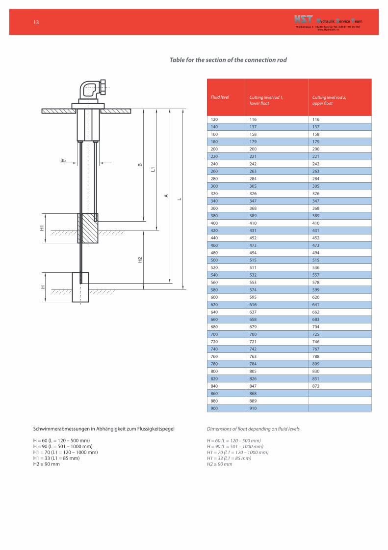
Table for the section of the connection rod
Schwimmerabmessungen in Abhängigkeit zum Flüssigkeitspegel
H = 60 (L = 120 – 500 mm)H = 90 (L = 501 – 1000 mm)H1 = 70 (L1 = 120 – 1000 mm)H1 = 33 (L1 = 85 mm)H2 ≥ 90 mm
Dimensions of float depending on fluid levels
H = 60 (L = 120 – 500 mm)H = 90 (L = 501 – 1000 mm)H1 = 70 (L1 = 120 – 1000 mm)H1 = 33 (L1 = 85 mm)H2 ≥ 90 mm
35
H1
L
A
L1
H
BH
2
Fluid level Cutting level rod 1,lower float
Cutting level rod 2,upper float
120 116 116
140 137 137
160 158 158
180 179 179
200 200 200
220 221 221
240 242 242
260 263 263
280 284 284
300 305 305
320 326 326
340 347 347
360 368 368
380 389 389
400 410 410
420 431 431
440 452 452
460 473 473
480 494 494
500 515 515
520 511 536
540 532 557
560 553 578
580 574 599
600 595 620
620 616 641
640 637 662
660 658 683
680 679 704
700 700 725
720 721 746
740 742 767
760 763 788
780 784 809
800 805 830
820 826 851
840 847 872
860 868
880 889
900 910
14
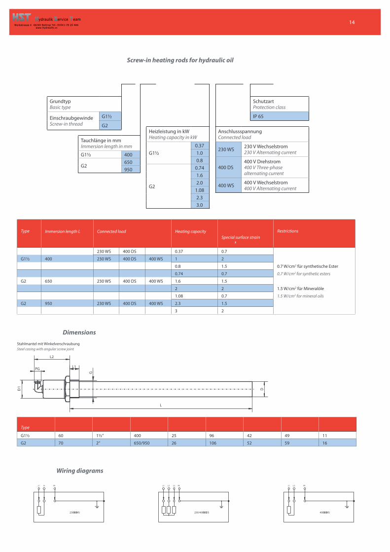
Screw-in heating rods for hydraulic oil
GrundtypBasic type
EinschraubgewindeScrew-in thread
G1½
G2
Tauchlänge in mmImmersion length in mm
G1½ 400
G2650950
Heizleistung in kWHeating capacity in kW
G1½0.371.00.8
G2
0.741.62.0
1.082.33.0
AnschlussspannungConnected load
230 WS 230 V Wechselstrom230 V Alternating current
400 DS400 V Drehstrom400 V Three-phasealternating current
400 WS 400 V Wechselstrom400 V Alternating current
SchutzartProtection class
IP 65
Dimensions
Stahlmantel mit WinkelverschraubungSteel casing with angular screw joint
Wiring diagrams
D
L
L2
L1
G
D1
PG
230/400�V�DS
L3 PEL2L1
400�V�WS
PEL2L1
230�V�WS
PENL1
Type Immersion length L Connected load Heating capacitySpecial surface strain
2
Restrictions
230 WS 400 DS 0.37 0.7
G1½ 400 230 WS 400 DS 400 WS 1 2
0.8 1.5 0.7 W/cm2 für synthetische Ester
0.74 0.7 0.7 W/cm2 for synthetic esters
G2 650 230 WS 400 DS 400 WS 1.6 1.5
2 2 1.5 W/cm2 für Mineralöle
1.08 0.7 1.5 W/cm2 for mineral oils
G2 950 230 WS 400 DS 400 WS 2.3 1.5
3 2
Type
G1½ 60 1½ ‘‘ 400 25 96 42 49 11
G2 70 2‘‘ 650/950 26 106 52 59 16
15
10°C
20°C
30°C
40°C
50°C
60°C
5
4
32
1
3kW 2kW 1kW 0,75kW 0,5kW
0,37kW
0,25kW
2000
[°C
]t
1500 1000 630 400 250 160 100 63V [I]1250 800 300 200
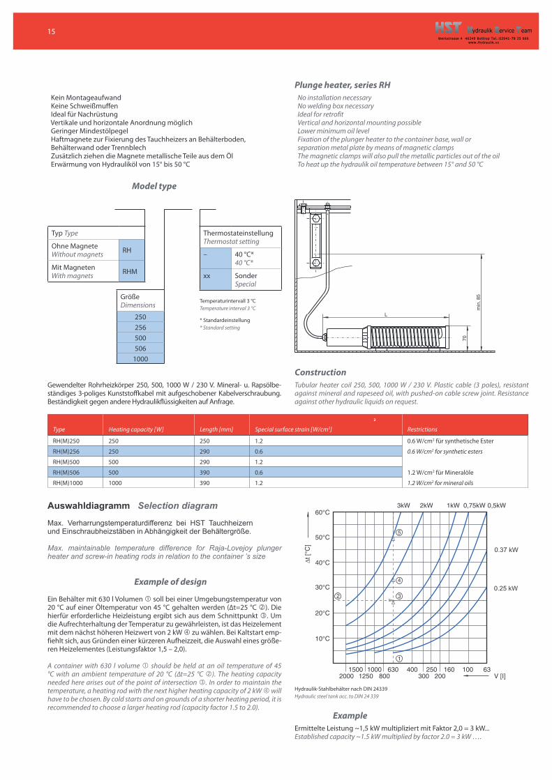
Kein Montageaufwand Keine Schweißmuffen Ideal für Nachrüstung Vertikale und horizontale Anordnung möglich Geringer Mindestölpegel Haftmagnete zur Fixierung des Tauchheizers an Behälterboden,Behälterwand oder Trennblech Zusätzlich ziehen die Magnete metallische Teile aus dem Öl Erwärmung von Hydrauliköl von 15° bis 50 °C
Plunge heater, series RH
No installation necessaryNo welding box necessaryIdeal for retrofitVertical and horizontal mounting possibleLower minimum oil levelFixation of the plunger heater to the container base, wall orseparation metal plate by means of magnetic clampsThe magnetic clamps will also pull the metallic particles out of the oilTo heat up the hydraulik oil temperature between 15° and 50 °C
Model type
Typ Type
Ohne MagneteWithout magnets RH
Mit MagnetenWith magnets RHM
GrößeDimensions
250256500506
1000
ThermostateinstellungThermostat setting
– 40 °C*40 °C*
xx SonderSpecial
Temperaturintervall 3 °CTemperature interval 3 °C
* Standardeinstellung* Standard setting
Gewendelter Rohrheizkörper 250, 500, 1000 W / 230 V. Mineral- u. Rapsölbe-ständiges 3-poliges Kunststoffkabel mit aufgeschobener Kabelverschraubung.Beständigkeit gegen andere Hydraulikflüssigkeiten auf Anfrage.
Construction
Tubular heater coil 250, 500, 1000 W / 230 V. Plastic cable (3 poles), resistantagainst mineral and rapeseed oil, with pushed-on cable screw joint. Resistanceagainst other hydraulic liquids on request.
Auswahldiagramm Selection diagram
Max. Verharrungstemperaturdifferenz bei HST Tauchheizernund Einschraubheizstäben in Abhängigkeit der Behältergröße.
Max. maintainable temperature difference for Raja-Lovejoy plungerheater and screw-in heating rods in relation to the container ’s size
Example of design
Ein Behälter mit 630 l Volumen � soll bei einer Umgebungstemperatur von20 °C auf einer Öltemperatur von 45 °C gehalten werden (Δt=25 °C �). Diehierfür erforderliche Heizleistung ergibt sich aus dem Schnittpunkt �. Umdie Aufrechterhaltung der Temperatur zu gewährleisten, ist das Heizelementmit dem nächst höheren Heizwert von 2 kW � zu wählen. Bei Kaltstart emp-fiehlt sich, aus Gründen einer kürzeren Aufheizzeit, die Auswahl eines größe-ren Heizelementes (Leistungsfaktor 1,5 – 2,0).
A container with 630 l volume � should be held at an oil temperature of 45°C with an ambient temperature of 20 °C (Δt=25 °C �). The heating capacityneeded here arises out of the point of intersection �. In order to maintain thetemperature, a heating rod with the next higher heating capacity of 2 kW � willhave to be chosen. By cold starts and on grounds of a shorter heating period, it isrecommended to choose a larger heating rod (capacity factor 1.5 to 2.0).
85m
in.
70
L
Hydraulik-Stahlbehälter nach DIN 24339Hydraulic steel tank acc. to DIN 24 339
Example
Ermittelte Leistung ~1,5 kW multipliziert mit Faktor 2,0 = 3 kW...Established capacity ~1.5 kW multiplied by factor 2.0 = 3 kW … .
Type Heating capacity [W] Length [mm]
2
Special surface strain [W/cm2] Restrictions
RH(M)250 250 250 1.2 0.6 W/cm2 für synthetische Ester
RH(M)256 250 290 0.6 0.6 W/cm2 for synthetic esters
RH(M)500 500 290 1.2
RH(M)506 500 390 0.6 1.2 W/cm2 für Mineralöle
RH(M)1000 1000 390 1.2 1.2 W/cm2 for mineral oils
0.37 kW
0.25 kW
16www.Hydraulik.vc
Tel. +49 (0) 20 41 / 78 25 666Fax +49 (0) 20 41 / 78 28 620E-Mail: [email protected]
Technische Änderungen vorbehaltenAlubehä lter/Behä lterzubehö rAl-Reservoirs/Accessories
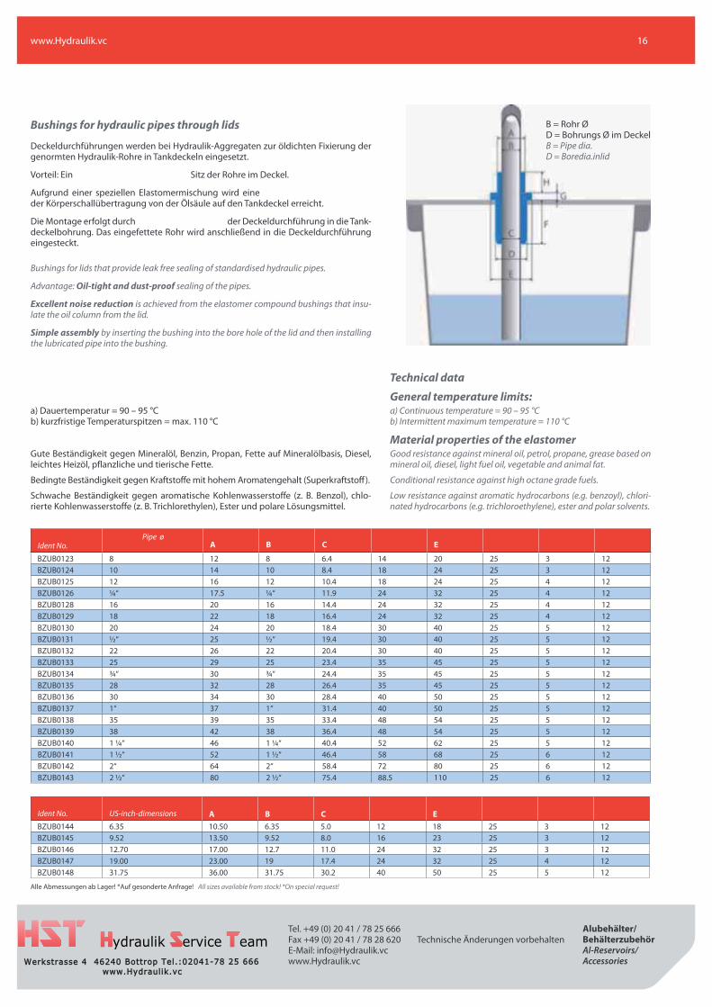
Bushings for hydraulic pipes through lids
Deckeldurchführungen werden bei Hydraulik-Aggregaten zur öldichten Fixierung dergenormten Hydraulik-Rohre in Tankdeckeln eingesetzt.
Vorteil: Ein Sitz der Rohre im Deckel.
Aufgrund einer speziellen Elastomermischung wird eineder Körperschallübertragung von der Ölsäule auf den Tankdeckel erreicht.
Die Montage erfolgt durch der Deckeldurchführung in die Tank-deckelbohrung. Das eingefettete Rohr wird anschließend in die Deckeldurchführungeingesteckt.
Bushings for lids that provide leak free sealing of standardised hydraulic pipes.
Advantage: Oil-tight and dust-proof sealing of the pipes.
Excellent noise reduction is achieved from the elastomer compound bushings that insu-late the oil column from the lid.
Simple assembly by inserting the bushing into the bore hole of the lid and then installingthe lubricated pipe into the bushing.
B = Rohr ØD = Bohrungs Ø im DeckelB = Pipe dia.D = Boredia.inlid
a) Dauertemperatur = 90 – 95 °Cb) kurzfristige Temperaturspitzen = max. 110 °C
Gute Beständigkeit gegen Mineralöl, Benzin, Propan, Fette auf Mineralölbasis, Diesel,leichtes Heizöl, pflanzliche und tierische Fette.
Bedingte Beständigkeit gegen Kraftstoffe mit hohem Aromatengehalt (Superkraftstoff ).
Schwache Beständigkeit gegen aromatische Kohlenwasserstoffe (z. B. Benzol), chlo-rierte Kohlenwasserstoffe (z. B. Trichlorethylen), Ester und polare Lösungsmittel.
Technical data
General temperature limits:a) Continuous temperature = 90 – 95 °Cb) Intermittent maximum temperature = 110 °C
Material properties of the elastomerGood resistance against mineral oil, petrol, propane, grease based onmineral oil, diesel, light fuel oil, vegetable and animal fat.
Conditional resistance against high octane grade fuels.
Low resistance against aromatic hydrocarbons (e.g. benzoyl), chlori-nated hydrocarbons (e.g. trichloroethylene), ester and polar solvents.
Alle Abmessungen ab Lager! *Auf gesonderte Anfrage! All sizes available from stock! *On special request!
Ident No.Pipe ø
A B C E
BZUB0123 8 12 8 6.4 14 20 25 3 12BZUB0124 10 14 10 8.4 18 24 25 3 12BZUB0125 12 16 12 10.4 18 24 25 4 12BZUB0126 ¼ ‘‘ 17.5 ¼ ‘‘ 11.9 24 32 25 4 12BZUB0128 16 20 16 14.4 24 32 25 4 12BZUB0129 18 22 18 16.4 24 32 25 4 12BZUB0130 20 24 20 18.4 30 40 25 5 12BZUB0131 ½ ‘‘ 25 ½ ‘‘ 19.4 30 40 25 5 12BZUB0132 22 26 22 20.4 30 40 25 5 12BZUB0133 25 29 25 23.4 35 45 25 5 12BZUB0134 ¾ ‘‘ 30 ¾ ‘‘ 24.4 35 45 25 5 12BZUB0135 28 32 28 26.4 35 45 25 5 12BZUB0136 30 34 30 28.4 40 50 25 5 12BZUB0137 1‘‘ 37 1‘‘ 31.4 40 50 25 5 12BZUB0138 35 39 35 33.4 48 54 25 5 12BZUB0139 38 42 38 36.4 48 54 25 5 12BZUB0140 1 ¼ ‘‘ 46 1 ¼ ‘‘ 40.4 52 62 25 5 12BZUB0141 1 ½ ‘‘ 52 1 ½ ‘‘ 46.4 58 68 25 6 12BZUB0142 2‘‘ 64 2‘‘ 58.4 72 80 25 6 12BZUB0143 2 ½ ‘‘ 80 2 ½ ‘‘ 75.4 88.5 110 25 6 12
Ident No. US-inch-dimensions A B C EBZUB0144 6.35 10.50 6.35 5.0 12 18 25 3 12BZUB0145 9.52 13.50 9.52 8.0 16 23 25 3 12BZUB0146 12.70 17.00 12.7 11.0 24 32 25 3 12BZUB0147 19.00 23.00 19 17.4 24 32 25 4 12BZUB0148 31.75 36.00 31.75 30.2 40 50 25 5 12


![MUTO COMFORT L 80 / XL 150 · MUTO COMFORT L 80 / XL 150 — DORMA 3. L 80 XL 150L 80. max. Türflügelbreite [mm] Türflügelglasdicke [mm] Türflügelgewicht [kg] 2000 8-13,5](https://img.pdfslide.org/doc/110x75/5e19941a512c80687624f5b3/muto-comfort-l-80-xl-150-muto-comfort-l-80-xl-150-a-dorma-3-l-80-xl-150l.jpg)


![Kompaktfilter – HS-ECO Pak … · Nennvolumenstrom [m 3/h] Flanschmaße für Standardtiefen X und Y Rahmentiefe [mm] X [mm] Y [mm] 78 /150 20 22 100 19 25 150 (1) / 292 (1) 20 21](https://img.pdfslide.org/doc/110x75/5f0705497e708231d41ae686/kompaktfilter-a-hs-eco-pak-nennvolumenstrom-m-3h-flanschmae-fr-standardtiefen.jpg)