Embed Size (px)
Citation preview

ANALYSIS AND IMPLEMENTATION OF PRODUCT MANUFACTURING INFORMATION AT TAMK
Sven Weper BACHELOR’S THESIS May 2019 Mechanical Engineering Allgemeiner Maschinenbau Double Degree
II
ABSTRACT
Tampereen ammattikorkeakoulu Tampere University of Applied Sciences Degree Programme in Mechanical Engineering Hochschule Hannover – University of Applied Sciences and Arts Fakultät Ⅱ – Maschinenbau und Bioverfahrenstechnik Studiengang Allgemeiner Maschinenbau (MAB-AM) WEPER, SVEN: Analysis and Implementation of Product Manufacturing Information at TAMK Bachelor's Thesis 82 pages, appendices 9 pages May 2019
The purpose of this Bachelor's Thesis was to identify requirements for the use of Prod-uct Manufacturing Information (PMI) for Coordinate Measuring Machine (CMM) in-spections at Tampere University of Applied Sciences (TAMK) and analyze benefits and risks. Research work classified PMI in context of Model-Based Definition (MBD) and outlined the current state and significance of this technology. A practical implementation test in this thesis included the generation of PMI data in Siemens PLM NX 11 CAD and subsequent reuse for inspection using Mitutoyo MiCAT Planner 1.6 software and Crysta-Apex S 574 CMM. This process indicated, that the use of PMI data can increasingly automate CMM programming, but software compatibility is currently a restrictive factor. MiCAT Planner does not support PMI in neutral file formats, which causes dependency on certain CAD systems and can limit data ex-change. MBD and the use of PMI data is currently not widely used but will yield more importance in different engineering processes.
Das Ziel dieser Bachelorarbeit war die Ermittlung von Anforderungen für die Nutzung von Produkt Manufacturing Information (PMI) für Messungen mit Koordinatenmess-maschinen (KMM) und Analyse von Vorteilen und Risiken. Innerhalb von Recherche-arbeit wurde PMI in den Zusammenhang mit Model-Based Definition (MBD) einge-ordnet und der gegenwärtige Stand und Bedeutung dieser Technologie dargestellt. Ein praktischer Test zur Umsetzung im Rahmen dieser Bachelorarbeit beinhaltete die Erzeugung von PMI Daten mit dem CAD Programm Siemens PLM NX 11 und die Wiederverwendung für KMM Messungen unter Verwendung von Mitutoyo MiCAT Planner 1.6 Software und Crysta-Apex S 574 KMM. Dieser Vorgang zeigte, dass die Nutzung von PMI zur zunehmenden Automatisierung bei der Erstellung von KMM Programmen beiträgt, aber Software-Kompatibilität gegenwärtig ein begrenzender Fak-tor ist. MiCAT Planner unterstützt PMI nicht in neutralen Dateiformaten, was zur Ab-hängigkeit bestimmter CAD Programme führt und den Dateiaustausch einschränkt. MBD und die Nutzung von PMI Daten ist gegenwärtig nicht sehr verbreitet, aber die Bedeutung wird zukünftig in verschiedenen Prozessen des Ingenieurwesens zunehmen.
Key words: Product Manufacturing Information (PMI); Coordinate Measuring Machine (CMM); Model-Based Definition (MBD); Mitutoyo MiCAT Planner
III
CONTENTS
Ⅰ LIST OF FIGURES .................................................................................................... V
Ⅱ LIST OF TABLES ...................................................................................................VII
Ⅲ ABBREVIATIONS AND TERMS ........................................................................ VIII
1 INTRODUCTION ....................................................................................................... 1
2 THEORY AND CLASSIFICATION OF MBD AND PMI ........................................ 2 2.1 Technical communication .................................................................................... 2 2.2 Model-Based Enterprise (MBE) .......................................................................... 4 2.3 Model-Based Definition (MBD) .......................................................................... 6 2.4 Product Manufacturing Information (PMI) ......................................................... 7
2.4.1 Graphical PMI ........................................................................................... 9 2.4.2 Semantic PMI .......................................................................................... 10
2.5 Different levels of technical communication and product definition ................ 10 2.6 Ranking of MBD and PMI in selected product lifecycle phases ....................... 12
2.6.1 Product development and construction ................................................... 13 2.6.2 Product manufacturing ............................................................................ 15 2.6.3 Quality inspection ................................................................................... 16
3 STATE OF SCIENCE AND TECHNOLOGY ......................................................... 17 3.1 Background on MBD technology ...................................................................... 17 3.2 Current utilization of MBD in industry ............................................................. 18 3.3 Technical literature and standards ..................................................................... 19 3.4 MBD and PMI in current CAD systems and CMM applications ...................... 21 3.5 Initial situation at TAMK .................................................................................. 22
3.5.1 Coordinate Measuring Machine: Mitutoyo Crysta-Apex S 574 ............. 23 3.5.2 Mitutoyo MiCAT Planner ....................................................................... 25
4 METHOD AND THESIS OBJECTIVE ................................................................... 27
5 IMPLEMENTATION OF PMI ................................................................................. 29 5.1 Test workpiece development and construction .................................................. 29
5.1.1 Requirements for test workpiece ............................................................. 29 5.1.2 CAD modelling of test workpieces ......................................................... 31 5.1.3 Change of CAD model to closed solid model ......................................... 33
5.2 Adding PMI annotations to the solid workpiece model .................................... 34 5.2.1 Definition of workpiece datums .............................................................. 35
IV
5.2.2 Definition of geometric workpiece tolerances ........................................ 36 5.2.3 Adding of workpiece dimensional PMI .................................................. 38 5.2.4 PMI in 3D-CAD model view .................................................................. 39
5.3 Save 3D-CAD model including PMI ................................................................. 39 5.4 Import of workpiece 3D-CAD model containing PMI ...................................... 40
5.4.1 Dimensional Measuring Equipment (DME) selection ............................ 44 5.4.2 Design model placement ......................................................................... 44
5.5 Generation of CMM program ............................................................................ 45 5.6 CMM inspection of test workpiece .................................................................... 47
6 RESULTS .................................................................................................................. 48 6.1 Requirements for PMI implementation ............................................................. 48
6.1.1 CAD software.......................................................................................... 48 6.1.2 Supported CAD models .......................................................................... 49 6.1.3 Supported PMI annotations ..................................................................... 50 6.1.4 Supported file formats ............................................................................. 52 6.1.5 CMM software environment ................................................................... 53
6.2 Benefits of PMI implementation ........................................................................ 54 6.2.1 CMM programs ....................................................................................... 54 6.2.2 Increase of productivity........................................................................... 54 6.2.3 Reducing errors ....................................................................................... 56
6.3 Risks of PMI implementation ............................................................................ 56 6.3.1 Dependence on CAD systems ................................................................. 56 6.3.2 CAD models ............................................................................................ 57 6.3.3 Compatibility between CAD software and CMM software .................... 58
7 CONCLUSION AND OUTLOOK ........................................................................... 59
REFERENCES ................................................................................................................ 62
DECLARATION OF AUTHORSHIP ............................................................................ 64
APPENDICES ................................................................................................................ 65 Appendix 1. 2D drawing of correct test workpiece ................................................... 65 Appendix 2. 2D drawing of defective test workpiece ............................................... 66 Appendix 3. Translation results of imported test workpiece STEP AP242 file ........ 67 Appendix 4. Translation results of imported test workpiece part file ....................... 69 Appendix 5. Measurement Report of correct test workpiece .................................... 72 Appendix 6. Measurement Report of defective test workpiece ................................ 73
V
Ⅰ LIST OF FIGURES
FIGURE 2-1: Simplified product lifecycle and some involved stakeholders ................ 3
FIGURE 2-2: Classification of MBD and PMI .............................................................. 5
FIGURE 2-3: Example of an MBD dataset .................................................................... 6
FIGURE 2-4: Examples of GD&T and non-geometric PMI .......................................... 8
FIGURE 2-5: Difference between graphical PMI and semantic PMI ............................ 9
FIGURE 2-6: Different levels of technical communication and product
definition ................................................................................................ 11
FIGURE 2-7: Ranking of MBD / PMI in product development-manufacturing-
inspection chain ..................................................................................... 12
FIGURE 2-8: Comparison of MBD (a) and model centric (b) concept in product
development and construction phase ..................................................... 14
FIGURE 3-1: CMM software environment at TAMK ................................................. 23
FIGURE 3-2: User interface of MiCAT Planner 1.6 ................................................... 26
FIGURE 4-1: Concept for PMI implementation .......................................................... 28
FIGURE 5-1: Basic workpiece geometry modelled in Siemens PLM NX 11 ............. 31
FIGURE 5-2: Final CAD model and model history of test workpiece ........................ 32
FIGURE 5-3: Supported CAD formats ........................................................................ 33
FIGURE 5-4: Procedure for the creation of a closed solid body in Siemens PLM
NX 11 .................................................................................................... 33
FIGURE 5-5: Solid body in model history of Siemens PLM NX 11 ........................... 34
FIGURE 5-6: Activating of PMI application in Siemens PLM NX 11 ....................... 34
FIGURE 5-7: User Interface of PMI Application in Siemens PLM NX 11 ................ 35
FIGURE 5-8: Definition of test workpiece position tolerance (PMI-No. (4)) in
Siemens PLM NX 11 ............................................................................. 36
FIGURE 5-9: Definition of linear dimension PMI-No. (10) in Siemens PLM
NX 11 .................................................................................................... 38
FIGURE 5-10: Overview of PMI-No. (1)-(12) added to the workpiece CAD
model ..................................................................................................... 39
FIGURE 5-11: Generation of a STEP AP242 file in Siemens PLM NX 11 .................. 40
FIGURE 5-12: Home tab with five basic MiCAT Planner operations .......................... 41
VI
FIGURE 5-13: Imported part file in 3D View and associated PMI in
Characteristic Reporting View .............................................................. 41
FIGURE 5-14: Comparison of PMI data generated in Siemens PLM NX 11 and
reused in Mitutoyo MiCAT Planner 1.6 ................................................ 42
FIGURE 5-15: Workpiece placement on CMM table and collision avoidance
zone ........................................................................................................ 44
FIGURE 5-16: Extract from generated CMM program with explanations .................... 46
FIGURE 5-17: Extract from part program after translating to GEOPAK with
explanations ........................................................................................... 47
FIGURE 6-1: Error message of imported design model referring to table 6-1 a) ........ 50
FIGURE 6-2: CMM programming time savings.......................................................... 55
VII
Ⅱ LIST OF TABLES
TABLE 2-1: Selected PMI examples referring to figure 2-4 ....................................... 8
TABLE 3-1: ASME standards in context with MBD ................................................. 20
TABLE 3-2: ISO standards in context with MBD...................................................... 20
TABLE 3-3: MBD / PMI applications in common CAD software ............................ 21
TABLE 3-4: PMI applications in common CMMs .................................................... 21
TABLE 3-5: Technical data of CAS574 ..................................................................... 24
TABLE 5-1: List of requirements for test workpiece development ........................... 30
TABLE 5-2: Defined test workpiece datums .............................................................. 35
TABLE 5-3: Definition of test workpiece tolerances ................................................. 37
TABLE 5-4: Definition of test workpiece dimensions ............................................... 38
TABLE 5-5: Summary of imported design models .................................................... 40
TABLE 5-6: Comparison of PMI data generated in Siemens PLM NX 11 and
reused in Mitutoyo MiCAT Planner 1.6 after importing design
model ..................................................................................................... 43
TABLE 6-1: Comparison of supported / not supported CAD models in MiCAT
Planner ................................................................................................... 49
TABLE 6-2: PMI reference objects for hole features ................................................. 51
TABLE 6-3: Interpretability of dimensional PMI for MiCAT Planner ...................... 51
TABLE 6-4: Supported Siemens PLM NX 11 file formats for MiCAT Planner
import..................................................................................................... 52
VIII
Ⅲ ABBREVIATIONS AND TERMS
.prt Part file in CAD software applications
.stp STEP file
.x_t Parasolid Model Part File
2D Two-dimensional
3D Three-dimensional
AB Aktiebolag (Swedish name for a limited company)
AG Aktiengesellschaft (public limited company)
AL Level of automation
AP Application Protocol
ASME American Society of Mechanical Engineers
CAD Computer-Aided Design
CAE Computer-Aided Engineering
CAM Computer-Aided Manufacturing
CAS574 Crysta-Apex S 574
CAx Computer-Aided X (X - technologies)
CMM Coordinate Measuring Machine
CNC Computer Numerical Control
DME Dimensional Measuring Equipment
DMIS Dimensional Measuring Interface Standard
e.g. For example (exempli gratia)
EWL Effective Working Length
FEA Finite Element Analysis
FT&A Functional Tolerancing and Annotation
GD&T Geometric Dimensioning and Tolerancing
GPS Geometrical Product Specifications
HsH Hochschule Hannover – University of Applied Sciences and
Arts
Inc. Incorporated
ISO International Organization for Standardization
Max. Maximum
MB Megabyte
MBD Model-Based Definition
MBE Model-Based Enterprise
IX
MCOSMOS Mitutoyo Controlled Open Systems for Modular Operation
Support
METSTA Mechanical Engineering and Metals Industry Standardiza-
tion in Finland
MiCAT Mitutoyo Intelligent Computer Aided Technology
MPE Maximum Permissible Error
N.d. No date
No. Number
PDM Product Data Management
PLC Product Life Cycle
PLM Product Lifecycle Management
PMI Product Manufacturing Information
QA Quality Assurance
SFS Finnish Standards Association (Suomen Standardisoimisliit-
to SFS ry)
STEP Standard for the Exchange of Product Model Data
TAMK Tampereen ammattikorkeakoulu (Tampere University of
Applied Sciences)
TDP Technical Data Package
TPD Technical Product Documentation
US United States
VDI Verein Deutscher Ingenieure (The Association of German
Engineers)
1
1 INTRODUCTION
Product information have been exchanged through two-dimensional technical drawings
between different actors in a product lifecycle for decades. This reliable method of
transferring technical product information is still the predominant way of technical
communication in many engineering processes, although the product modelling is done
in 3D using CAD systems. Why do not completely share product information with 3D-
CAD models and expand their functionality in order to replace 2D drawings?
CAD, as an already approved standard in product development processes nowadays,
offers the possibility to append all information included in an engineering drawing and
additional technical data directly to the 3D-CAD model. Replacing 2D drawings
through annotated 3D-CAD models cause fundamental changes in technical communi-
cation and revolutionize the exchange of technical information through datasets within a
product lifecycle. Communicating product information through digital annotated 3D-
CAD models and enable the use of this data in engineering workflows is called Model-
Based Definition (MBD). A dedicated group of those annotations are Product Manufac-
turing Information (PMI). Once PMI were added to the CAD model, this data can be
reused in downstream engineering processes like manufacturing or inspection, which is
the main benefit of PMI within MBD workflows.
Tampere University of Applied Sciences (TAMK) is involved in research projects about
MBD and is initially going to integrate the use of PMI for CMM inspection.
The aim of this Bachelor´s Thesis is to analyse and implement the use of PMI at
TAMK. Background and classification of MBD and PMI, extended with research about
the state of science and technology form the first part of this thesis.
A practical implementation process, beginning from the CAD modelling of a developed
test object using Siemens PLM NX 11, to the final CMM inspection based on PMI us-
ing Mitutoyo MiCAT Planner 1.6 is included in the second part of this thesis.
This process investigated, how reuse of PMI data in CMM inspection as a selected
downstream engineering process is possible with available hardware and software with-
in TAMK’s mechanical engineering laboratories. Requirements, as well as benefits and
risks were identified and form the basis for the handling of PMI related work packages
for CMM inspection in the future.
2
2 THEORY AND CLASSIFICATION OF MBD AND PMI
2.1 Technical communication
Technical communication is the way to exchange technical information between differ-
ent stakeholders within the whole product lifecycle. In this process, engineering
knowledge in accordance with a product circulates to guarantee a safe, effective and
efficient use of a product (tcworld GmbH, n.d.).
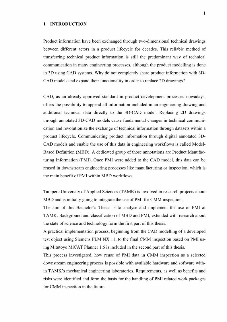
Figure 2-1 shows a general technical product lifecycle starting from an innovation,
which is an introduction of a new product or device. After the product runs through dif-
ferent development phases, beginning from the conceptual design to the final product
construction, manufacturing processes are initiated. Manufactured products must pass
the final quality inspection, before they are delivered to the customer. Depending on the
product, a manual installation or final assembly by the customer might be necessary.
Subsequently, the product is ready for operation and is usually used until the lifespan is
exceeded or the product gets broken and proper functionality is not possible anymore.
During the product operation, repair and maintenance work might be necessary. Finally,
the product is disposed or can be recycled. New technologies, changes and improve-
ments of the previous product are some reasons for continuous development and inno-
vations. A modified or new innovative product sets the initial point for the product
lifecycle to start again.
The general product lifecycle in figure 2-1 shows the significance of distinct technical
communication through technical drawings within the product lifecycle. This lifecycle
in figure 2-1 is a simplified illustration without details or referring to a specified product
and its main purpose is to outline technical communication in the context of digital
product definition based on MBD for this thesis work.
From the first conceptual design of an innovation, derived from a simple paper-based
sketch of an idea, engineering drawings are mandatory for all further steps in order to
guarantee accurate technical communication between different actors involved in the
product lifecycle. Engineering drawings must transfer product definition in a clear, ex-
plicit, understandable and concise way among different stakeholders throughout the
product lifecycle (Quintana et al. 2010, 501). Product information must be traceable and
comprehensible for a product designer, construction engineer, production scheduler,
external suppliers, sales engineer and quality engineer. In addition, the customer, certi-
fication authorities and other stakeholders are also involved in technical communication
based on technical drawings.
3
FIGURE 2-1: Simplified product lifecycle and some involved stakeholders (inspired from tcworld GmbH, n.d.)
This extensive exchange of information on a product and networking between different
stakeholders throughout a product lifecycle, as well as the ability to manage the entire
lifecycle is called product lifecycle management (PLM).
Technical drawings are predicated on international standards (e.g. series ISO 128 Tech-
nical drawings - General principles of presentation) and its fundamental purpose is to
carry, control and maintain a products definition in a precise and clear way with no risk
of misinterpretation or assumption (Quintana et al. 2010, 497). They have become the
main instrument for managing product information, define product characteristics and
confirm their actual compliance (Ricci et al. 2014, 36). Visual abstractions, standardised
symbols and clearly defined methods are used to communicate complex technical as-
semblies and parts in a comprehensible manner.
The communication is most effective, when different stakeholders within the product
lifecycle can understand and use their relevant information provided by an engineering
drawing or latterly by a 3D-CAD model with annotations.
Product designers
Construction engineers
Quality engineers
Suppliers
Production scheduler
Calculation engineers
Sales engineers
Certification authorities
…
Customers
PLC
-Stakeholders
exchange product information through technical com
munication
4
2.2 Model-Based Enterprise (MBE)
The term “Model-Based Enterprise” is related to the whole product lifecycle (figure 2-
1) and a 3D-CAD model as part of a Technical Data Package1 (TDP) includes all neces-
sary product information for the entire cycle and involved stakeholders. It is a generic
term for a business initiative, where a 3D-CAD model with additional information re-
places various sets of engineering drawings and is utilized in as many product lifecycle
processes as possible. It is not only a companywide strategy, as this 3D-CAD model is
used within the entire supply chain and different downstream users and suppliers re-
ceive product information for their purpose from that TDP, which is a common database
for all operators. The term MBE also describes the development of hardware and com-
puter graphics, which makes the view and utilisation of 3D models containing digital
annotations and information throughout the product lifecycle possible (Cicconi et al.
2016, 526).
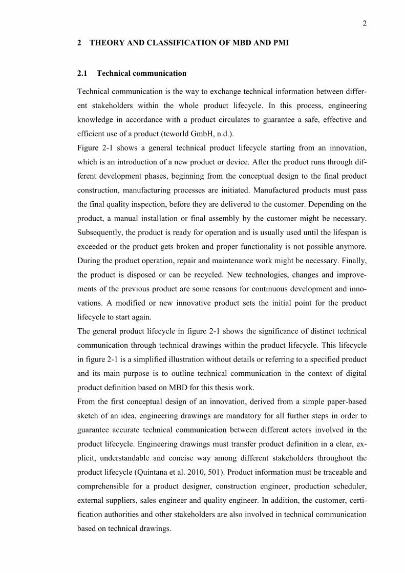
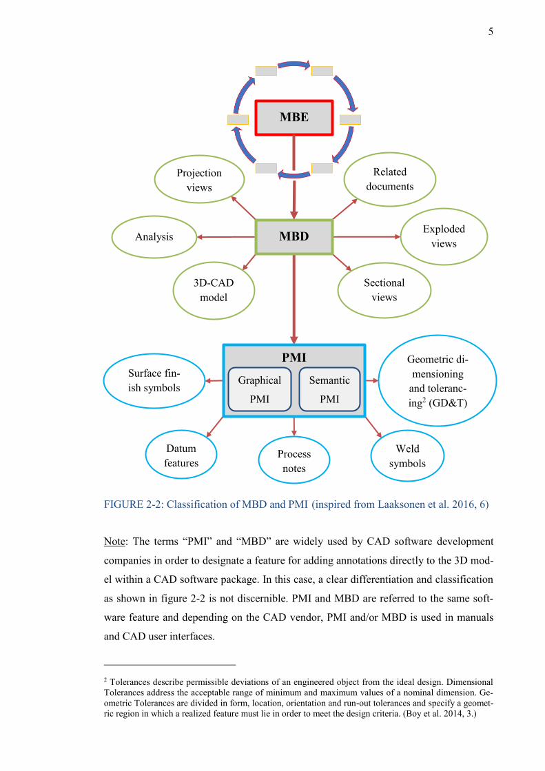
Figure 2-2 shows the general classification and delimitation of the MBE term in a clear
manner. Arrows arranged in a circle around the MBE term emblematise, that this term
always refers to the entire product lifecycle and the 3D model in a TDP is the basis for
technical communication and the source for product information for all workflows.
MBD can be derived from MBE and always refers to the actual 3D-CAD modelling.
Furthermore, Product Manufacturing Information (PMI) are part of MBD and the rela-
tion and differentiation between those terms is shown in figure 2-2. The amount of
product information and actors in MBD is less than included in the MBE term.
This Bachelor’s Thesis will focus on MBD and especially the use of PMI. As figure 2-2
shows, both terms are derived from MBE and can always be reduced to MBE.
MBE is more related to an economic strategic orientation within an entire product
lifecycle and will not be examined in this thesis work. The definition of MBE is used
for the classification of MBD and PMI only, which are the main subjects of this thesis.
1 A TDP includes a technical description of an item and contains data for supporting an acquisition, pro-duction, engineering and logistics support (e.g. Engineering Data for Provisioning, Training and Tech-nical Manuals). The description defines the required design configuration or performance requirements, and procedures required to ensure adequacy of item performance. It consists of applicable technical data such as models, drawings, associated lists, specifications, standards, performance requirements, quality assurance provisions, software documentations, and packing details. (MIL-STD-31000A. 2013, 8-9 sec-tion 3.1.37.)
5
FIGURE 2-2: Classification of MBD and PMI2(inspired from Laaksonen et al. 2016, 6)
Note: The terms “PMI” and “MBD” are widely used by CAD software development
companies in order to designate a feature for adding annotations directly to the 3D mod-
el within a CAD software package. In this case, a clear differentiation and classification
as shown in figure 2-2 is not discernible. PMI and MBD are referred to the same soft-
ware feature and depending on the CAD vendor, PMI and/or MBD is used in manuals
and CAD user interfaces.
2 Tolerances describe permissible deviations of an engineered object from the ideal design. Dimensional Tolerances address the acceptable range of minimum and maximum values of a nominal dimension. Ge-ometric Tolerances are divided in form, location, orientation and run-out tolerances and specify a geomet-ric region in which a realized feature must lie in order to meet the design criteria. (Boy et al. 2014, 3.)
3D-CAD model
Projection views
Analysis
Related documents
Exploded views
Sectional views
MBD
MBE
Surface fin-ish symbols
Datum features
Geometric di-mensioning
and toleranc-ing2 (GD&T)
PMI
Graphical
PMI
Semantic
PMI
Weld symbols
Process notes
6
2.3 Model-Based Definition (MBD)
The term “Model-Based definition” is referred to Computer-aided x (CAx) technologies
and represents in all a method for transferring engineering information. A 3D-CAD
model is the master file that holds all product information and fully defines the product
(Bijnens et al. 2018, 314). It contains all necessary data to specify a product, which can
be used in downstream processes and MBD is used in conjunction with the implementa-
tion of digital manufacturing technologies. In differentiation to MBE, a 3D-CAD model
included in an MBD dataset only incorporates product information, which makes prod-
uct manufacturing, component assembly or inspection possible.
“An MBD dataset contains the exact solid, its associated 3D geometry and 3D Product
Manufacturing Information (PMI) of the product’s dimensions and tolerances (and may
include parts/notes lists) to specify a complete product definition.” (Quintana et al.
2010, 498).
According to figure 2-2, this information can be the solid 3D-CAD model including
Product Manufacturing Information (PMI) like dimensions and tolerances, analyses as
well as exploded and sectional views and attached external documents. Supplemental
geometry elements, such as center lines or datum targets are no real features on the
model, but communicate design requirements and are included in an MBD dataset as
well. The solid 3D model can be manipulated in CAD systems and the dataset can be
exported to CAE and CAM software in order to optimize the product definition and
define machine-readable instructions. Unified rules and standardizations in technical
communication are applied to express geometric dimensions and tolerances, which are
added to a unique 3D-CAD model and included in an MBD dataset.
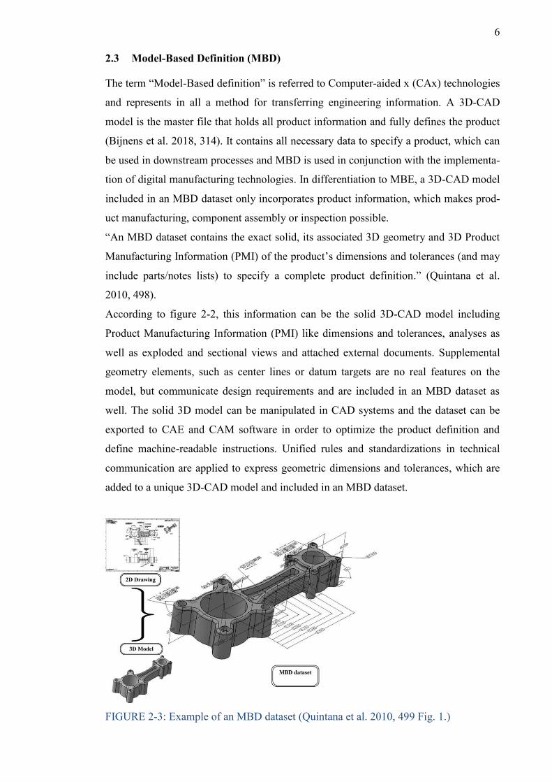
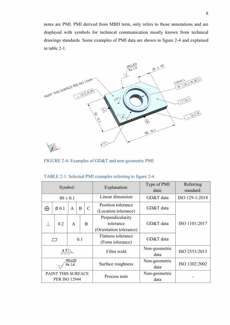
FIGURE 2-3: Example of an MBD dataset (Quintana et al. 2010, 499 Fig. 1.)
7
All data elements associated to a 3D-CAD model are enough for product definition and
there is no need for 2D drawings anymore. Therefore, the MBD term is often referred to
a digital product definition strategy, which describes the transition from 2D drawings to
3D-CAD models, but is no synonymous expression for paperless engineering. Those
drawingless 3D-CAD models contain the same amount of information as displayed in
2D drawings and are the source for geometry and detailed product definition. In most
engineering processes, the product to be manufactured is defined through the coexist-
ence of a 3D-CAD model and a 2D drawing derived from that model. Instead of having
two separate files, the 2D drawing and the solid 3D-CAD-model fuse into an MBD da-
taset (figure 2-3). This MBD dataset contains the same information from the 2D draw-
ing with additional information, by adding all dimensions and annotations to the 3D-
CAD model, which can be used in downstream engineering processes.
MBD is an advanced way of antecedent product definition methods and a change within
technical communication, which nowadays is a trend to appear in different manufactur-
ing industries. This change to 3D-CAD models through MBD also affects the product
development process and is expanded from constructive design to the manufacturing
process and the final quality inspection (section 2.6).
2.4 Product Manufacturing Information (PMI)
Product Manufacturing Information (PMI) are referred to 3D-CAD systems and the
term is imbedded in MBD as shown in figure 2-2. The term “PMI” includes annotations
to specify Geometric Dimensioning and Tolerancing (GD&T) and non-geometric data
associated with a CAD model as part of the MBD dataset (Lipman et al. 2015, 15).
All those 3D annotations are commonly referred as PMI data by commercial CAD liter-
ature and its primary purpose is to represent the product’s physical and functional re-
quirements (Quintana et al. 2010, 498).
PMI as part of the MBD term includes those kinds of annotations, which are used to
define a product geometry and its specifications in accordance with standards. All re-
quirements for a proper part manufacturing and inspection, like GD&T are conveyed
through PMI and embedded into a 3D-CAD model. The 3D model acts as a legitimate
and sanctioned method for the complete documentation of PMI (Siemens PLM Soft-
ware Inc. 2011, 1). In addition, this PMI data generated in CAD software conveys prod-
uct definition information and supports the reuse in analysing, manufacturing and in-
spection processes. Attributes like GD&T, datum features, surface properties (e.g.
roughness), weld symbols, material specifications, finish requirements and process
8
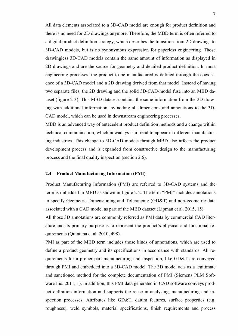
notes are PMI. PMI derived from MBD term, only refers to those annotations and are
displayed with symbols for technical communication mostly known from technical
drawings standards. Some examples of PMI data are shown in figure 2-4 and explained
in table 2-1.
FIGURE 2-4: Examples of GD&T and non-geometric PMI
TABLE 2-1: Selected PMI examples referring to figure 2-4
Symbol: Explanation: Type of PMI
data: Referring standard:
80 ± 0.1 Linear dimension GD&T data ISO 129-1:2018
⊕ ∅ 0.1 A B C Position tolerance
(Location tolerance) GD&T data
ISO 1101:2017 ⏊ 0.2 A B Perpendicularity
tolerance (Orientation tolerance)
GD&T data
▱ 0.1 Flatness tolerance (Form tolerance)
GD&T data
Fillet weld
Non-geometric data
ISO 2553:2013
Surface roughness Non-geometric
data ISO 1302:2002
PAINT THIS SURFACE PER ISO 12944 Process note
Non-geometric data
-
9
The product information contained in the MBD term include PMI, which are only
linked to GD&T and specific non-geometric data to enable interrogation in downstream
engineering processes like manufacturing and inspection. The term MBD is used in the
entirety of digital product development and ensures a complete 2D drawingless product
definition. MBD includes more content from technical drawings and views with addi-
tional information to define a product and comprises CAD elements from the solid 3D
model.
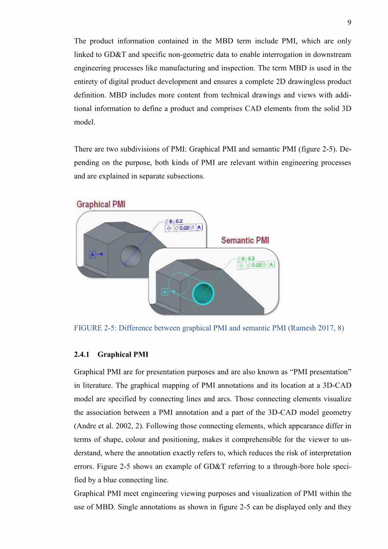
There are two subdivisions of PMI: Graphical PMI and semantic PMI (figure 2-5). De-
pending on the purpose, both kinds of PMI are relevant within engineering processes
and are explained in separate subsections.
FIGURE 2-5: Difference between graphical PMI and semantic PMI (Ramesh 2017, 8)
2.4.1 Graphical PMI
Graphical PMI are for presentation purposes and are also known as “PMI presentation”
in literature. The graphical mapping of PMI annotations and its location at a 3D-CAD
model are specified by connecting lines and arcs. Those connecting elements visualize
the association between a PMI annotation and a part of the 3D-CAD model geometry
(Andre et al. 2002, 2). Following those connecting elements, which appearance differ in
terms of shape, colour and positioning, makes it comprehensible for the viewer to un-
derstand, where the annotation exactly refers to, which reduces the risk of interpretation
errors. Figure 2-5 shows an example of GD&T referring to a through-bore hole speci-
fied by a blue connecting line.
Graphical PMI meet engineering viewing purposes and visualization of PMI within the
use of MBD. Single annotations as shown in figure 2-5 can be displayed only and they
10
are not directly associated with a cylinder object (through-bore hole) within the 3D-
CAD model. Different viewers and actors of the product lifecycle can use PMI directly
added to a 3D-CAD model instead of getting them out of 2D drawings. In this case,
graphical PMI comply the same technical communication purpose as in 2D drawings
but displayed in a 3D format. They are not consumable by any downstream manufactur-
ing or inspection software and can be used for non-automated manufacturing and in-
spection processes by retrieving PMI manually from the annotated 3D-CAD model.
2.4.2 Semantic PMI
Semantic PMI are machine readable and for representation purposes. They are also
known as “PMI representation” in literature.
Semantic PMI are character based and complement graphical PMI. Information about
the type, value and reference are stored within semantic PMI and are readable for soft-
ware packages. Semantic PMI contain numerical values and it is determined to which
references theses values refer to (Bijnens et al. 2018, 315). There is no presentation pur-
pose and semantic PMI enable the utilization of computer-interpretable applications in
downstream engineering processes. Semantic PMI, which have been added to a 3D-
CAD model, can be reused in machining and inspection PLC phases, which is a funda-
mental benefit and contributes to more automation.
The selected position tolerance PMI of the through-bore hole in figure 2-5 shows, that
references are assigned within the entire workpiece when using semantic PMI. This
selected PMI is associated to a cylinder feature (through-bore hole) and is provided in a
machine-readable data format. It makes the reuse of CAD data for different stakeholders
in downstream engineering applications possible and GD&T included in semantic PMI
can be transferred from CAD to CAM and CMM software. Semantic PMI embedded in
CAD data is processed in CMM software and supports the automatic generation of
measurement programs.
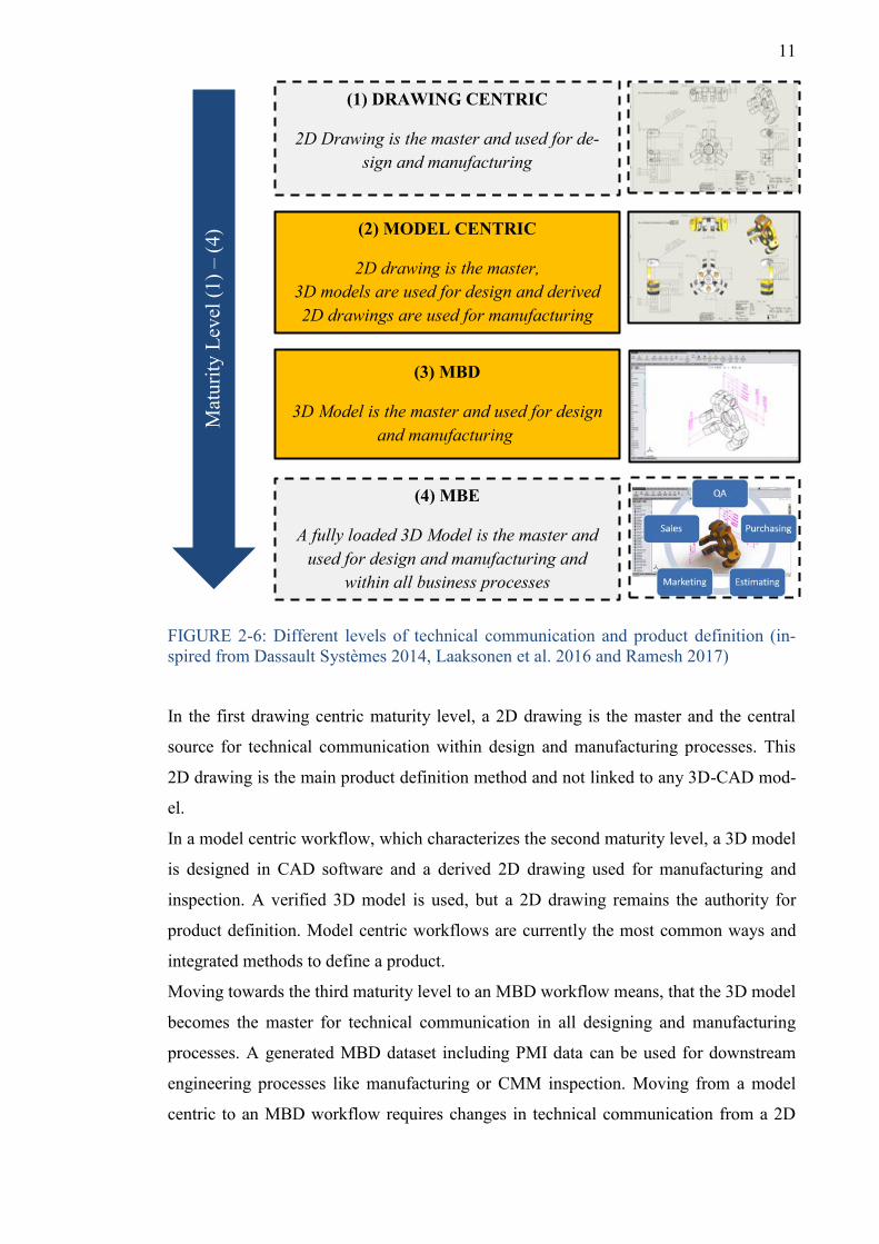
2.5 Different levels of technical communication and product definition
According to Dassault Systèmes, Laaksonen et al. and Ramesh there are four different
maturity levels when moving from a drawing-based workflow to an MBE environment.
The different levels are visualized in figure 2-6 and briefly described in the following.
11
FIGURE 2-6: Different levels of technical communication and product definition (in-spired from Dassault Systèmes 2014, Laaksonen et al. 2016 and Ramesh 2017)
In the first drawing centric maturity level, a 2D drawing is the master and the central
source for technical communication within design and manufacturing processes. This
2D drawing is the main product definition method and not linked to any 3D-CAD mod-
el.
In a model centric workflow, which characterizes the second maturity level, a 3D model
is designed in CAD software and a derived 2D drawing used for manufacturing and
inspection. A verified 3D model is used, but a 2D drawing remains the authority for
product definition. Model centric workflows are currently the most common ways and
integrated methods to define a product.
Moving towards the third maturity level to an MBD workflow means, that the 3D model
becomes the master for technical communication in all designing and manufacturing
processes. A generated MBD dataset including PMI data can be used for downstream
engineering processes like manufacturing or CMM inspection. Moving from a model
centric to an MBD workflow requires changes in technical communication from a 2D
(1) DRAWING CENTRIC
2D Drawing is the master and used for de-sign and manufacturing
M
atur
ity L
evel
(1) –
(4) (2) MODEL CENTRIC
2D drawing is the master, 3D models are used for design and derived 2D drawings are used for manufacturing
(3) MBD
3D Model is the master and used for design and manufacturing
(4) MBE
A fully loaded 3D Model is the master and used for design and manufacturing and
within all business processes
12
Product development
Product release
Product development and construction
Product manufacturing Quality inspection
Manual gauging / CMM inspection.
Generation of a 3D-CAD model represent-ing the final product design and including
all PMI data.
Manual manufac-turing or auto-
mated manufac-turing using
CAM software.
reuse of PMI data
drawing to an annotated 3D-CAD model and changes in equipment acquisition in terms
of software and hardware are necessary.
The fourth maturity level describes an MBE approach, which means that a fully loaded
3D model in a TDP is used by different users within a product lifecycle. As this term is
linked to a business strategy with more complex processes and networks between dif-
ferent actors, it is not taken into consideration for this thesis.
Especially the second and third maturity level, which are highlighted in orange and ac-
centuated by bold lines in figure 2-6, show the transition from a model centric towards
MBD workflow and are relevant levels for this thesis work.
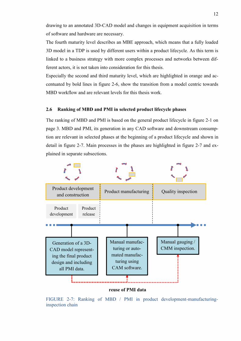
2.6 Ranking of MBD and PMI in selected product lifecycle phases
The ranking of MBD and PMI is based on the general product lifecycle in figure 2-1 on
page 3. MBD and PMI, its generation in any CAD software and downstream consump-
tion are relevant in selected phases at the beginning of a product lifecycle and shown in
detail in figure 2-7. Main processes in the phases are highlighted in figure 2-7 and ex-
plained in separate subsections.
FIGURE 2-7: Ranking of MBD / PMI in product development-manufacturing-inspection chain
13
2.6.1 Product development and construction
Basis for the beginning of the product development and construction phase could be an
innovation, modification of an existing product or a customer request for the construc-
tion of a device. A list of requirements for the final product, which a contractor has
agreed on with a client has usually to be done before.
The product development and construction phase can be split into product development
phase and product release phase (Quintana et al. 2010, 500). Within the product devel-
opment phase, the conceptual design based on a sketch is developed and more details
are added. Besides, the requirement list is considered and listed functional needs should
be realized within the construction. The final design is the result of this phase and the
initial point for the production release phase. It is a continuous increase of the product
definition level and finally all relevant information are included in the construction, so
that downstream engineering processes can begin.
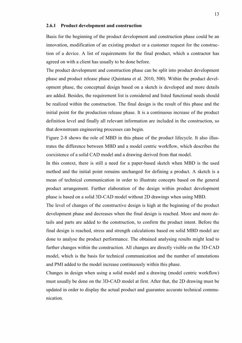
Figure 2-8 shows the role of MBD in this phase of the product lifecycle. It also illus-
trates the difference between MBD and a model centric workflow, which describes the
coexistence of a solid CAD model and a drawing derived from that model.
In this context, there is still a need for a paper-based sketch when MBD is the used
method and the initial point remains unchanged for defining a product. A sketch is a
mean of technical communication in order to illustrate concepts based on the general
product arrangement. Further elaboration of the design within product development
phase is based on a solid 3D-CAD model without 2D drawings when using MBD.
The level of changes of the constructive design is high at the beginning of the product
development phase and decreases when the final design is reached. More and more de-
tails and parts are added to the construction, to confirm the product intent. Before the
final design is reached, stress and strength calculations based on solid MBD model are
done to analyse the product performance. The obtained analysing results might lead to
further changes within the construction. All changes are directly visible on the 3D-CAD
model, which is the basis for technical communication and the number of annotations
and PMI added to the model increase continuously within this phase.
Changes in design when using a solid model and a drawing (model centric workflow)
must usually be done on the 3D-CAD model at first. After that, the 2D drawing must be
updated in order to display the actual product and guarantee accurate technical commu-
nication.
14
FIGURE 2-8: Comparison of MBD (a) and model centric (b) concept in product devel-opment and construction phase (Quintana et al. 2010, 500 Fig. 2.)
In the product development and construction phase, the final MBD model is a 3D digital
prototype and ready for manufacturing (Zhu et al. 2016, 487). Its primary purpose is the
creation of digital product datasets of the final design including PMI, which can be used
in subsequent product manufacturing and quality inspection phases. The responsibility
and workload of a product designer in an MBD workflow increases compared to a mod-
el centric workflow. Reuse of PMI data in subsequent PLC phases must already be con-
sidered and ensured in product development and construction phase.
In order to enable interoperability and use of PMI data generated in this phase in follow-
ing software applications for manufacturing and inspection, a suitable data format is
required. As involved stakeholders might use different CAD software, the conversion is
an important procedure to make an exchange of PMI data and the reuse within down-
stream applications possible. Neutral file formats (e.g. STEP), which are based on inter-
national standards or CAD software related data formats (e.g. part file) and supported in
downstream applications, must equally represent PMI data, as generated during product
development and construction phase.
15
2.6.2 Product manufacturing
Dedicated content of the MBD dataset including PMI, which was generated in the pre-
vious product development and construction phase, can be reused in the subsequent
product manufacturing phase.
For the manufacturing of workpieces using manual machining methods, MBD including
all necessary PMI serves as an alternative to 2D drawings. Machine operators or me-
chanics working on the shop floor level can get all necessary dimensional and tolerance
information for manufacturing from an annotated 3D model including PMI. Such tasks
like manual milling, lathing or drilling can be performed using GD&T information from
graphical PMI, which are displayed on a screen or tablet. Graphical PMI distribute the
product definition as part of technical communication between the product development
and construction department and machine operators. They can retrieve graphical PMI to
control manual manufacturing and are the source for proper machine setting adjustment.
PMI data can be used for the automation of CNC programming tasks, which are usually
done prior to the real manufacturing process. CAM software uses the 3D-CAD model
with PMI provided in a dedicated file format to define and validate machine-readable
instructions for manufacturing (Lipman et al. 2015, 15). Semantic PMI can facilitate
CNC programming tasks by generating optimized toolpaths as features and forms of an
imported CAD model and information about tolerance and surface quality are readable
for CAM software. CAM software often adopt the nominal dimension from the 3D-
CAD model to create the toolpath. In order to consider tolerances for toolpath pro-
gramming, manual adjustment is necessary by extracting tolerance data from 2D draw-
ings.
GD&T in semantic PMI are interpretable by proper CAM software and machine opera-
tors do not manually have to adjust the tolerances to the middle tolerance value any-
more, which reduces the risk of errors significantly.
Tools can be selected automatically and the parameter adjustment (e.g. speed, feed) is
done based on a 3D model including semantic PMI. In this context, the term Model-
Based Manufacturing (MBM) is used and PMI in this phase increase the level of auto-
mation3 and technical stuff on the shop floor is increasingly responsible for correct ex-
amination and supervision of the program functionality.
3 The level of automation is the relation between automated functions to the overall (manual + automated) functions of a production system in terms of costs or stages of production: 𝐴𝐿 = 𝑎𝑢𝑡𝑜𝑚𝑎𝑡𝑒𝑑
𝑚𝑎𝑛𝑢𝑎𝑙+𝑎𝑢𝑡𝑜𝑚𝑎𝑡𝑒𝑑 (1).
16
2.6.3 Quality inspection
The utilization of manual gauging and CMM for the final control of a products quality
is important during quality inspection phase and relevant in the context of MBD. Manu-
al gauging as a measuring method for a products quality evaluation can use graphical
PMI to display a products GD&T set values. Requirements expressed in GD&T and
other properties of the final product design, engineered in the product development and
construction phase and their compliance after product manufacturing must usually be
checked, before delivering the product to the customer.
Graphical PMI connected to a 3D-CAD model are the source to receive information
about the ideal geometric shape of a product and can be used instead of 2D drawings.
Measuring points can be shown by graphical PMI and a set-actual comparison between
the manufactured product dimensions and the ideal 3D model including PMI can be
performed.
Software packages from different metrological companies can read GD&T included in
semantic PMI, which have been attached to a 3D-CAD model and were provided in a
dedicated file format during product development and construction phase. CMM soft-
ware can use machine-readable PMI and the associated CAD model geometry to gener-
ate a measuring program for the check of GD&T and constraints such as perpendiculari-
ty or circularity of manufactured parts. Semantic PMI act as the central distributor for
products ideal GD&T properties, which are the source for measuring program genera-
tion and comparison with the real parts geometry. Based on predefined tolerances in-
cluded in semantic PMI, a manufactured part is evaluated, if it meets the tolerances or
not (Mitutoyo Corporation 2018, 10).
In this phase, semantic PMI enable an automatic creation of measuring programs for
CMMs and this increases the level of automation. Less time is spent on manual pro-
gramming by CMM technicians and extraction of GD&T from 2D drawings as a manu-
al input for CMM software is replaced by directly reading PMI from an imported file.
The software identifies features from the CAD geometry and PMI and prepares an ap-
propriate tool for inspection and previews the CMM probe inspection path in a simula-
tion environment. After CMM program execution and quality inspection of a product,
the delivered measurements are documented in a report.
17
3 STATE OF SCIENCE AND TECHNOLOGY
3.1 Background on MBD technology
3D modelling in CAD became possible in the 1980s and the product definition was
primary represented through 2D drawings. First ideas to add GD&T and all annotations
directly to 3D models as an alternative to 2D drawings came up around the turn of the
millennium. The term MBD and its extensive technology as described in section 2.3 and
shown in figure 2-2 did not exist during that time. It was initially an initiative to change
technical communication by using annotated 3D models without reuse of certain data
for further engineering processes. Continuous development and enhancement of product
definition based on 3D models was driven by CAD software development companies.
The Boeing4 company was one of the initiators of the MBD technology (Zhu et al.
2016, 486). Sharing Boeing’s expertise and supported by the American Society of Me-
chanical Engineers (ASME), research on MBD began in 1997 and a first MBD standard
(ASME Y14.41 2003 – Digital product definition data practices) was published in 2003.
This standard formed the basis for MBD and was latest updated in 2012. It is still im-
portant for 3D part definition practices using MBD in the US until today.
MBD applications were integrated in prevalent CAD software. For example, the French
company Dassault Systèmes, which developed the CAD program SolidWorks, pub-
lished a first 3D drawing application “eDrawings” in 1999. A first MBD dimensioning
software tool (DimXpert) included in SolidWorks was introduced in 2008 and complet-
ed by the release of SolidWorks MBD software package in 2015 (Dassault Systèmes
2014, 2). Other CAD software vendors, like Siemens PLM released an MBD applica-
tion in their CAD program NX about the same time.
Besides the implementation of the MBD technology in different CAD programs, down-
stream engineering CAE and CAM software was advanced to make PMI data utilisable.
CMM manufacturer like Mitutoyo released software in 2014, in order to use semantic
PMI data for the generation of automatic part measurement programs, which reduces
time and effort to create CMM programs.
4 Boeing is a US based aerospace company and the largest manufacturer of civil and military aircrafts worldwide.
18
3.2 Current utilization of MBD in industry
The progress of MBD implementation in industry is on a different level, dependent on
the branch of industry. Applying MBD workflows is more common in the US. Especial-
ly in aerospace, automotive and defence industries it is widely-used and those industries
are currently the main drivers of the MBD trend (Quintana et al. 2010, 506). For exam-
ple, the Boeing company adopted MBD for designing parts of the Boeing 777 aircraft.
Suppliers and external industrial partners were involved in a complete digital product
definition process in an MBE environment. Adopting MBD was required for Boeings
subcontractors, if they were considered as suppliers.
In other industries, MBD is currently less utilized and slowly becomes more popular.
According to figure 2-6, the model centric concept (second maturity level) is still the
predominant workflow in most industries and all the single data including the 3D-CAD
model and the corresponding 2D drawings are often managed in a PDM/PLM system.
Some industries are thinking of adopting MBD into operating procedures or are current-
ly in a transition period of MBD implementation. Companies need to decide, if restruc-
turing from a model centric workflow to an MBD workflow is worthwhile and realiza-
ble. There are currently only few single companies which utilized MBD besides aero-
space and automotive.
Furthermore, there are industries, where some actors within a product lifecycle already
start to use MBD, but this technology is not completely adopted in the whole product
lifecycle yet. An example is the Finnish automotive supplier Valmet Automotive Inc.5,
which shares MBD data with Daimler AG (Simons, J. 2019). A rapid spread and indus-
try-wide trend of MBD utilization is in many cases retarded through concerns about a
complete renunciation of 2D drawings (Ruemler et al. 2017, 6). 2D drawings are gener-
ally seen as a safe and proven way of transferring technical product definition. Imple-
mentation of MBD in an industrial company means changing the way of technical
communication, when getting rid of 2D drawings and downstream engineering process-
es are affected. It is a barrier which needs to be overcome and a general view on the
diverse manufacturing industrial sector exempt from aerospace and automotive de-
scribes, that MBD is not widely utilized yet, but the MBD concept accepted in industry
(Ruemler et al. 2017, 2).
5 Valmet Automotive Inc. is an upstream provider for the automotive industry based in Uusikaupunki, Finland. The company was founded in 1968 and provides engineering and manufacturing services for automobile industry. Customers are amongst others BMW, Daimler and Porsche.
19
There is currently no company in Finland, which implemented complete MBD work-
flows or uses PMI data in an appropriate CMM software for measuring program genera-
tion. The technology and use of PMI data slowly becomes popular and will be more
relevant in the future. (Vainio. 2019.) In general, the use and technology of PMI for
machining and inspection purposes in industry is still evolving and further improve-
ments are expected.
CAD software development companies included MBD and PMI in various software
packages and hold it in readiness. This group exposes MBD as an advanced technology
in a digital engineering environment and mentions the benefits of MBD. In order to
convince more companies towards MBD implementation, prevalent arguments are the
reduction of product development costs and delays due to inaccurate engineering draw-
ings (Quintana et al. 2010, 498).
The utilization of MBD and its influence on industry is currently discussed in science
and between different actors in industry. Several engineering associations like ASME
are publishing journal articles to introduce the MBD concept and outline its benefits and
risks based on industrial examples. This association is currently very active in the dis-
cussion of MBD and has developed standards (e.g. ASME Y14.41 – 2012: Digital
Product Definition Data Practices) for 3D model definition in cooperation with national
standardization institutes since the beginning of MBD technology.
National standardization institutes like METSTA in Finland are publishing reports in
cooperation with companies, universities and CAD software reseller, in order to give
advice and a guideline on MBD for Finnish industries. METSTA acts as an official and
reliable source for Finnish companies, which are thinking of adapting MBD and informs
about the opportunities of MBD workflows.
3.3 Technical literature and standards
There are different well-established international standards for technical communication
through technical drawings and requirements for technical product documentation.
Some already implemented standards for technical communication are valid in conjunc-
tion with MBD as well. The US standard ASME Y14.41 and international standard ISO
16792 are currently the standards for MBD technology and provide specifications about
digital product definition.
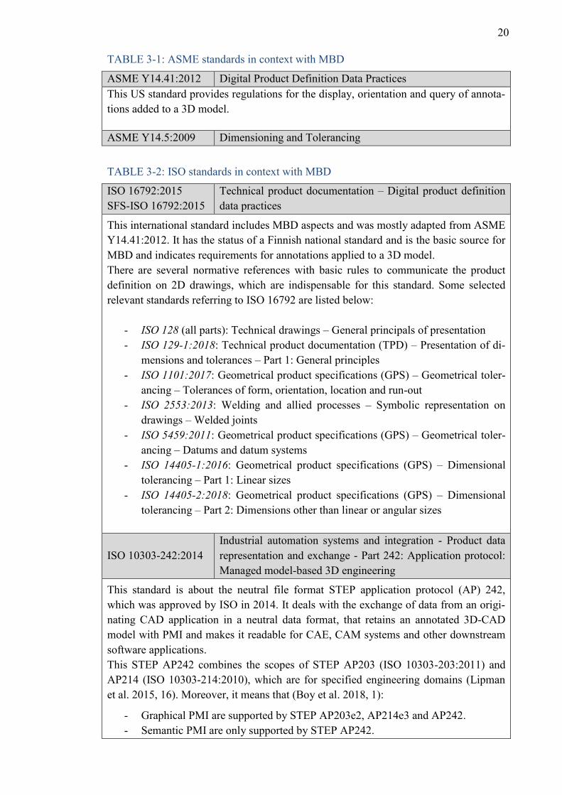
A brief overview about selected ASME and ISO standards concerning MBD is given in
tables 3-1 and 3-2.
20
TABLE 3-1: ASME standards in context with MBD
ASME Y14.41:2012 Digital Product Definition Data Practices This US standard provides regulations for the display, orientation and query of annota-tions added to a 3D model. ASME Y14.5:2009 Dimensioning and Tolerancing
TABLE 3-2: ISO standards in context with MBD
ISO 16792:2015 SFS-ISO 16792:2015
Technical product documentation – Digital product definition data practices
This international standard includes MBD aspects and was mostly adapted from ASME Y14.41:2012. It has the status of a Finnish national standard and is the basic source for MBD and indicates requirements for annotations applied to a 3D model. There are several normative references with basic rules to communicate the product definition on 2D drawings, which are indispensable for this standard. Some selected relevant standards referring to ISO 16792 are listed below:
- ISO 128 (all parts): Technical drawings – General principals of presentation - ISO 129-1:2018: Technical product documentation (TPD) – Presentation of di-
mensions and tolerances – Part 1: General principles - ISO 1101:2017: Geometrical product specifications (GPS) – Geometrical toler-
ancing – Tolerances of form, orientation, location and run-out - ISO 2553:2013: Welding and allied processes – Symbolic representation on
drawings – Welded joints - ISO 5459:2011: Geometrical product specifications (GPS) – Geometrical toler-
ancing – Datums and datum systems - ISO 14405-1:2016: Geometrical product specifications (GPS) – Dimensional
tolerancing – Part 1: Linear sizes - ISO 14405-2:2018: Geometrical product specifications (GPS) – Dimensional
tolerancing – Part 2: Dimensions other than linear or angular sizes
ISO 10303-242:2014 Industrial automation systems and integration - Product data representation and exchange - Part 242: Application protocol: Managed model-based 3D engineering
This standard is about the neutral file format STEP application protocol (AP) 242, which was approved by ISO in 2014. It deals with the exchange of data from an origi-nating CAD application in a neutral data format, that retains an annotated 3D-CAD model with PMI and makes it readable for CAE, CAM systems and other downstream software applications. This STEP AP242 combines the scopes of STEP AP203 (ISO 10303-203:2011) and AP214 (ISO 10303-214:2010), which are for specified engineering domains (Lipman et al. 2015, 16). Moreover, it means that (Boy et al. 2018, 1):
- Graphical PMI are supported by STEP AP203e2, AP214e3 and AP242. - Semantic PMI are only supported by STEP AP242.
21
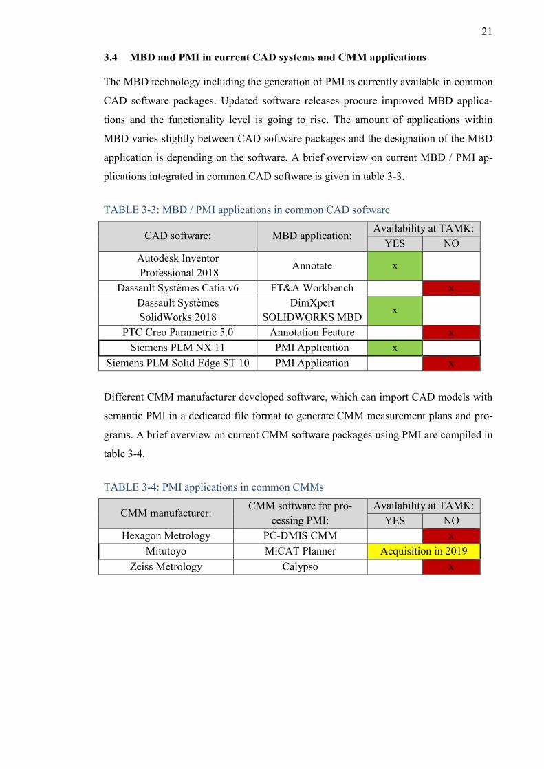
3.4 MBD and PMI in current CAD systems and CMM applications
The MBD technology including the generation of PMI is currently available in common
CAD software packages. Updated software releases procure improved MBD applica-
tions and the functionality level is going to rise. The amount of applications within
MBD varies slightly between CAD software packages and the designation of the MBD
application is depending on the software. A brief overview on current MBD / PMI ap-
plications integrated in common CAD software is given in table 3-3.
TABLE 3-3: MBD / PMI applications in common CAD software
CAD software: MBD application: Availability at TAMK:
YES NO Autodesk Inventor Professional 2018
Annotate x
Dassault Systèmes Catia v6 FT&A Workbench x Dassault Systèmes SolidWorks 2018
DimXpert SOLIDWORKS MBD
x
PTC Creo Parametric 5.0 Annotation Feature x Siemens PLM NX 11 PMI Application x
Siemens PLM Solid Edge ST 10 PMI Application x
Different CMM manufacturer developed software, which can import CAD models with
semantic PMI in a dedicated file format to generate CMM measurement plans and pro-
grams. A brief overview on current CMM software packages using PMI are compiled in
table 3-4.
TABLE 3-4: PMI applications in common CMMs
CMM manufacturer: CMM software for pro-
cessing PMI: Availability at TAMK:
YES NO Hexagon Metrology PC-DMIS CMM x
Mitutoyo MiCAT Planner Acquisition in 2019 Zeiss Metrology Calypso x
22
3.5 Initial situation at TAMK
TAMK is currently adopting new future-orientated technologies within mechanical en-
gineering laboratories (F0-19). MBD as a digital product definition technology and es-
pecially the use of PMI data in downstream engineering applications should be imple-
mented at TAMK and an analysis combined with a practical test for that process is per-
formed by this thesis work. Besides, some local companies are interested in ongoing
research projects about the use and implementation of PMI at TAMK.
Siemens PLM NX 11, Autodesk Inventor Professional 2018 and Dassault Systèmes
SolidWorks 2018 CAD software with MBD and PMI applications are currently availa-
ble (table 3-3), but PMI data has not been generated and used for any downstream engi-
neering processes at TAMK before.
The handling of the MBD applications within installed CAD systems and the generation
of PMI data is currently unknown. It is unidentified, what are the requirements and how
reuse of PMI data generated by available CAD software is possible in engineering pro-
cesses at TAMK, such as FEA or CMM inspection.
According to the different maturity levels of technical communication and product defi-
nition in figure 2-6, the initial situation at TAMK is ranked to the second maturity level,
which describes a model centric workflow. This initial situation correlates with the cur-
rent situation in Finnish industry, but changes and increasing significance of MBD
workflows including the use of PMI data are expected.
TAMKs mechanical engineering laboratory is equipped with a Mitutoyo CMM type
Crysta-Apex S 574, which currently uses Mitutoyo MCOSMOS6-3 v.4.1.R1 measure-
ment software for the inspection and dimensional analysis of parts. This CMM software
does not support PMI and the CMM measuring program generation based on PMI is
currently not possible. TAMK is going to purchase Mitutoyo MiCAT Planner software
in order to implement the use of PMI data for CMM inspection procedures in 2019.
The general ranking and significance of MiCAT Planner within TAMKs CMM software
environment is shown in figure 3-1.
6 MCOSMOS [Mitutoyo Controlled Open Systems for Modular Operation Support] is a modular CMM software system developed by MiCAT [Mitutoyo Intelligent Computer Aided Technology] for measuring and evaluating procedures within coordinate measuring technology. The software is currently available in three different levels (MCOSMOS 1/2/3), which differ in terms of included packages and can be expand-ed by optional modules.
23
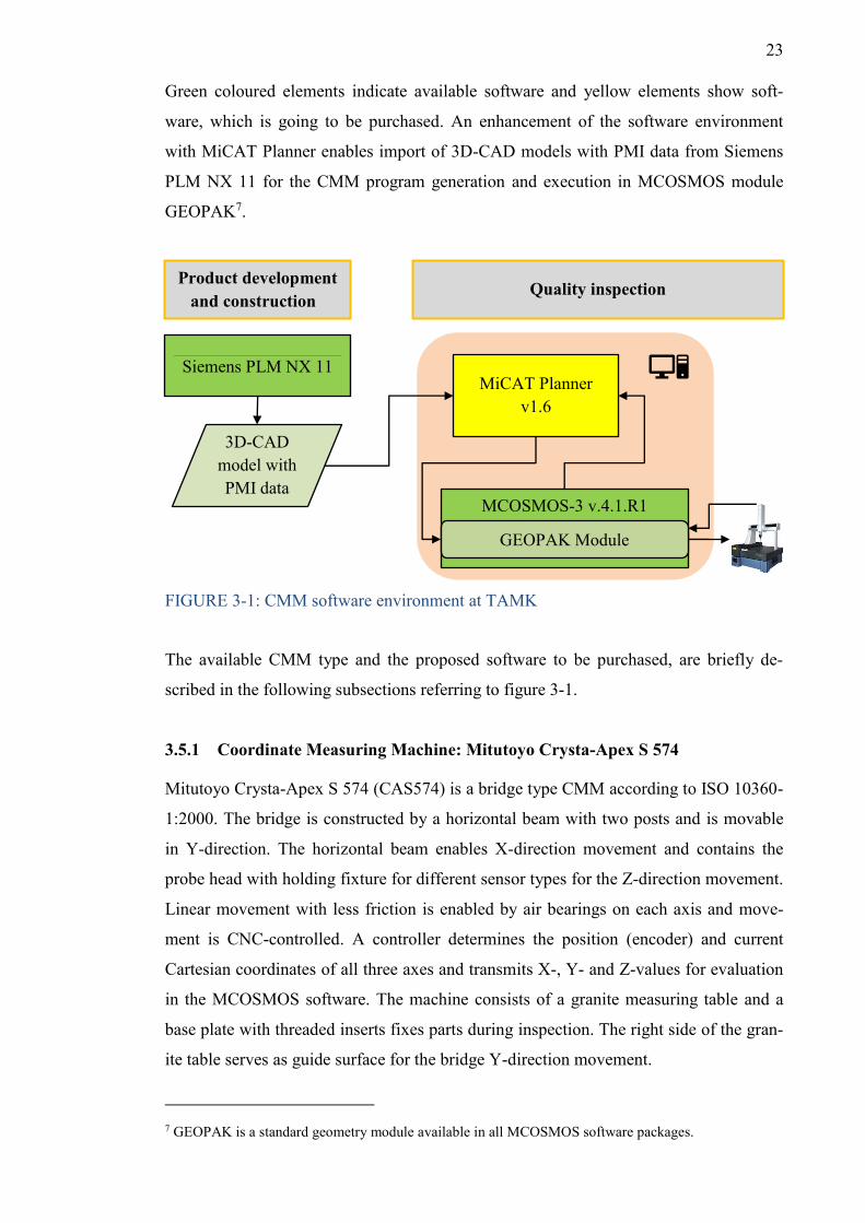
Green coloured elements indicate available software and yellow elements show soft-
ware, which is going to be purchased. An enhancement of the software environment
with MiCAT Planner enables import of 3D-CAD models with PMI data from Siemens
PLM NX 11 for the CMM program generation and execution in MCOSMOS module
GEOPAK7.
FIGURE 3-1: CMM software environment at TAMK
The available CMM type and the proposed software to be purchased, are briefly de-
scribed in the following subsections referring to figure 3-1.
3.5.1 Coordinate Measuring Machine: Mitutoyo Crysta-Apex S 574
Mitutoyo Crysta-Apex S 574 (CAS574) is a bridge type CMM according to ISO 10360-
1:2000. The bridge is constructed by a horizontal beam with two posts and is movable
in Y-direction. The horizontal beam enables X-direction movement and contains the
probe head with holding fixture for different sensor types for the Z-direction movement.
Linear movement with less friction is enabled by air bearings on each axis and move-
ment is CNC-controlled. A controller determines the position (encoder) and current
Cartesian coordinates of all three axes and transmits X-, Y- and Z-values for evaluation
in the MCOSMOS software. The machine consists of a granite measuring table and a
base plate with threaded inserts fixes parts during inspection. The right side of the gran-
ite table serves as guide surface for the bridge Y-direction movement.
7 GEOPAK is a standard geometry module available in all MCOSMOS software packages.
Product development and construction
Quality inspection
3D-CAD model with PMI data
Siemens PLM NX 11 MiCAT Planner
v1.6
MCOSMOS-3 v.4.1.R1
GEOPAK Module
24
CMMs are usually equipped with scanning or tactile switching probes. The latter probe
with synthetic ruby ball tip and changeable probe head angle is used for CMM inspec-
tion in context with this thesis. Discrete coordinate values are recorded when the stylus
tip touches different points on a part and are assigned to defined features like planes or
circles within the software. The X-, Y- and Z-coordinates of those points are recorded,
when the stylus tip touches the part surface and activates the tactile switching. Meas-
urement points form a scatter-plot and regression algorithms in MCOSMOS software
process the transmitted coordinate data. Based on this input data, e.g. distances or posi-
tions of features are calculated and geometrical forms (e.g. cylindricity, circularity) are
evaluated.
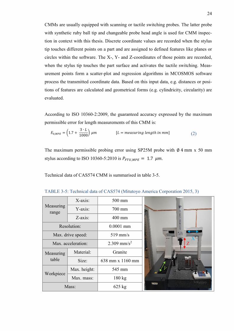
According to ISO 10360-2:2009, the guaranteed accuracy expressed by the maximum
permissible error for length measurements of this CMM is:
𝐸0,𝑀𝑃𝐸 = (1.7 + 3 ∙ 𝐿1000) 𝜇𝑚 [𝐿 = 𝑚𝑒𝑎𝑠𝑢𝑟𝑖𝑛𝑔 𝑙𝑒𝑛𝑔𝑡ℎ 𝑖𝑛 𝑚𝑚] (2)
The maximum permissible probing error using SP25M probe with ∅ 4 mm x 50 mm
stylus according to ISO 10360-5:2010 is 𝑃𝐹𝑇𝑈,𝑀𝑃𝐸 = 1.7 𝜇𝑚.
Technical data of CAS574 CMM is summarised in table 3-5.
TABLE 3-5: Technical data of CAS574 (Mitutoyo America Corporation 2015, 3)
Measuring range
X-axis: 500 mm
Y-axis: 700 mm
Z-axis: 400 mm
Resolution: 0.0001 mm
Max. drive speed: 519 mm/s
Max. acceleration: 2.309 mm/s2
Measuring table
Material: Granite
Size: 638 mm x 1160 mm
Workpiece Max. height: 545 mm
Max. mass: 180 kg
Mass: 625 kg
X Z
25
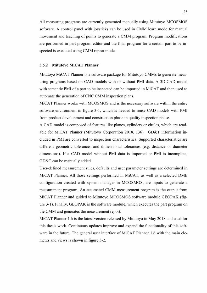
All measuring programs are currently generated manually using Mitutoyo MCOSMOS
software. A control panel with joysticks can be used in CMM learn mode for manual
movement and teaching of points to generate a CMM program. Program modifications
are performed in part program editor and the final program for a certain part to be in-
spected is executed using CMM repeat mode.
3.5.2 Mitutoyo MiCAT Planner
Mitutoyo MiCAT Planner is a software package for Mitutoyo CMMs to generate meas-
uring programs based on CAD models with or without PMI data. A 3D-CAD model
with semantic PMI of a part to be inspected can be imported in MiCAT and then used to
automate the generation of CNC CMM inspection plans.
MiCAT Planner works with MCOSMOS and is the necessary software within the entire
software environment in figure 3-1, which is needed to reuse CAD models with PMI
from product development and construction phase in quality inspection phase.
A CAD model is composed of features like planes, cylinders or circles, which are read-
able for MiCAT Planner (Mitutoyo Corporation 2018, 136). GD&T information in-
cluded in PMI are converted to inspection characteristics. Supported characteristics are
different geometric tolerances and dimensional tolerances (e.g. distance or diameter
dimensions). If a CAD model without PMI data is imported or PMI is incomplete,
GD&T can be manually added.
User-defined measurement rules, defaults and user parameter settings are determined in
MiCAT Planner. All those settings performed in MiCAT, as well as a selected DME
configuration created with system manager in MCOSMOS, are inputs to generate a
measurement program. An automated CMM measurement program is the output from
MiCAT Planner and guided to Mitutoyo MCOSMOS software module GEOPAK (fig-
ure 3-1). Finally, GEOPAK is the software module, which executes the part program on
the CMM and generates the measurement report.
MiCAT Planner 1.6 is the latest version released by Mitutoyo in May 2018 and used for
this thesis work. Continuous updates improve and expand the functionality of this soft-
ware in the future. The general user interface of MiCAT Planner 1.6 with the main ele-
ments and views is shown in figure 3-2.
26
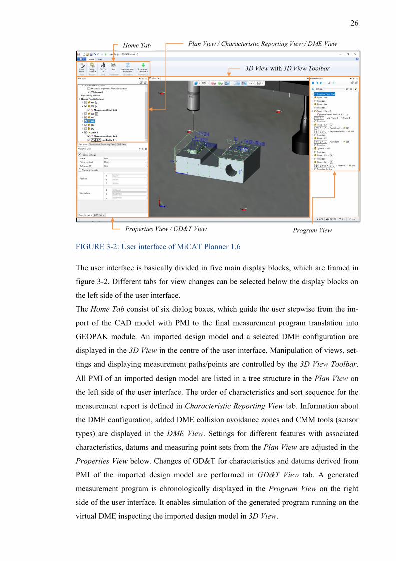
FIGURE 3-2: User interface of MiCAT Planner 1.6
The user interface is basically divided in five main display blocks, which are framed in
figure 3-2. Different tabs for view changes can be selected below the display blocks on
the left side of the user interface.
The Home Tab consist of six dialog boxes, which guide the user stepwise from the im-
port of the CAD model with PMI to the final measurement program translation into
GEOPAK module. An imported design model and a selected DME configuration are
displayed in the 3D View in the centre of the user interface. Manipulation of views, set-
tings and displaying measurement paths/points are controlled by the 3D View Toolbar.
All PMI of an imported design model are listed in a tree structure in the Plan View on
the left side of the user interface. The order of characteristics and sort sequence for the
measurement report is defined in Characteristic Reporting View tab. Information about
the DME configuration, added DME collision avoidance zones and CMM tools (sensor
types) are displayed in the DME View. Settings for different features with associated
characteristics, datums and measuring point sets from the Plan View are adjusted in the
Properties View below. Changes of GD&T for characteristics and datums derived from
PMI of the imported design model are performed in GD&T View tab. A generated
measurement program is chronologically displayed in the Program View on the right
side of the user interface. It enables simulation of the generated program running on the
virtual DME inspecting the imported design model in 3D View.
Properties View / GD&T View
Home Tab
3D View with 3D View Toolbar
Program View
Plan View / Characteristic Reporting View / DME View
27
4 METHOD AND THESIS OBJECTIVE
Based on the initial situation and currently available hardware and software at TAMK
(section 3.4 and 3.5), a concept for a first implementation of PMI was developed.
It includes the generation of PMI data using available CAD software Siemens PLM NX
11 at TAMK and subsequent reuse for CMM inspection using Mitutoyo Crysta-Apex S
574 and CMM programming software Mitutoyo MiCAT Planner 1.6. As Mitutoyo Mi-
CAT Planner was not available at TAMK, a practical test was done at Mitutoyo Scandi-
navia AB Finnish Branch facility in Pirkkala.
The concept comprised the manufacturing of two test workpieces using a CNC machin-
ing centre (type: Bridgeport VMC 600 XP) in TAMK’s machining shop, which are used
as sample objects for the PMI implementation during this thesis work. One workpiece
was manufactured without errors and should conform with all GD&T as defined in the
CAD model. The other workpiece has identical shape, but the geometrical properties
include errors, which are detectable through CMM inspection. To receive significant
results, the test workpieces had to meet several demands, which were initially consoli-
dated in a requirement list according to methodical guidelines of the product develop-
ment process in VDI 2221. This requirement list was the input for the product develop-
ment and construction phase and formed the original point for the workpiece geometry
designing process in Siemens PLM NX 11 CAD.
Different semantic PMI annotations by considering technical standards were added to
the 3D-CAD model and finally saved in a file format, which was used for CMM pro-
gramming with Mitutoyo MiCAT Planner software. In order to examine requirements,
how the CAD model must be designed and how PMI must be added to be supported by
MiCAT Planner, different files were imported by trial and error method.
Both manufactured test workpieces and the 3D-CAD model containing PMI data were
the final outcomes of the previous phases and transferred into quality inspection phase.
The files were imported in MiCAT planner software to generate a CMM program based
on PMI and the test workpieces were the objects for practical CMM inspection.
Requirements for the use of PMI data were outlined and benefits and risks identified
from that process. Main focus was on PMI generation practices during product devel-
opment and construction phase, as well as the use for quality inspection in MiCAT
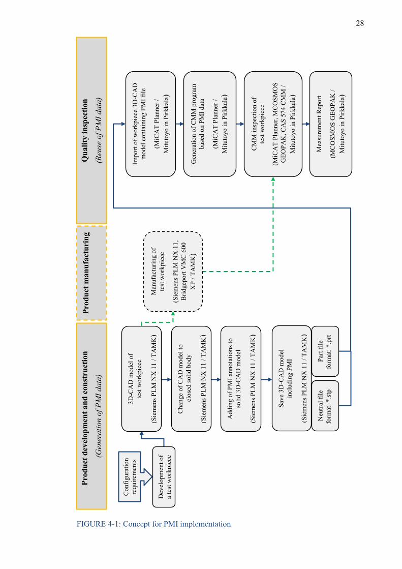
Planner. The entire concept of PMI implementation is demonstrated in the flow chart in
figure 4-1 and all processes are described in detail in the next chapter to form a guide-
line, how PMI can be used for CMM inspection at TAMK.
28
FIGURE 4-1: Concept for PMI implementation
Prod
uct d
evel
opm
ent a
nd c
onst
ruct
ion
(Gen
erat
ion
of P
MI d
ata)
Pr
oduc
t man
ufac
turi
ng
Q
ualit
y in
spec
tion
(Reu
se o
f PM
I dat
a)
Cha
nge
of C
AD
mod
el to
c
lose
d so
lid b
ody
(Sie
men
s PLM
NX
11
/ TA
MK
)
Add
ing
of P
MI a
nnot
atio
ns to
so
lid 3
D-C
AD
mod
el
(Sie
men
s PLM
NX
11
/ TA
MK
)
Save
3D
-CA
D m
odel
in
clud
ing
PMI
(Sie
men
s PLM
NX
11
/ TA
MK
)
Neu
tral f
ile
form
at: *
.stp
Pa
rt fil
e fo
rmat
: *.p
rt
Man
ufac
turin
g of
te
st w
orkp
iece
(Sie
men
s PLM
NX
11,
B
ridge
port
VM
C 6
00
XP
/ TA
MK
)
Impo
rt of
wor
kpie
ce 3
D-C
AD
m
odel
con
tain
ing
PMI f
ile
(MiC
AT
Plan
ner /
M
ituto
yo in
Pirk
kala
)
Gen
erat
ion
of C
MM
pro
gram
ba
sed
on P
MI d
ata
(MiC
AT
Plan
ner /
M
ituto
yo in
Pirk
kala
)
CM
M in
spec
tion
of
test
wor
kpie
ce
(MiC
AT
Plan
ner,
MC
OSM
OS
GEO
PAK
, CA
S 57
4 C
MM
/ M
ituto
yo in
Pirk
kala
)
Dev
elop
men
t of
a te
st w
orkp
iece
Con
figur
atio
n re
quire
men
ts
3D-C
AD
mod
el o
f te
st w
orkp
iece
(Sie
men
s PLM
NX
11
/ TA
MK
)
Mea
sure
men
t Rep
ort
(MC
OSM
OS
GEO
PAK
/
Mitu
toyo
in P
irkka
la)
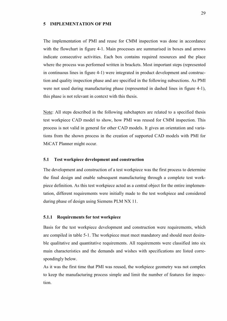
29
5 IMPLEMENTATION OF PMI
The implementation of PMI and reuse for CMM inspection was done in accordance
with the flowchart in figure 4-1. Main processes are summarised in boxes and arrows
indicate consecutive activities. Each box contains required resources and the place
where the process was performed written in brackets. Most important steps (represented
in continuous lines in figure 4-1) were integrated in product development and construc-
tion and quality inspection phase and are specified in the following subsections. As PMI
were not used during manufacturing phase (represented in dashed lines in figure 4-1),
this phase is not relevant in context with this thesis.
Note: All steps described in the following subchapters are related to a specified thesis
test workpiece CAD model to show, how PMI was reused for CMM inspection. This
process is not valid in general for other CAD models. It gives an orientation and varia-
tions from the shown process in the creation of supported CAD models with PMI for
MiCAT Planner might occur.
5.1 Test workpiece development and construction
The development and construction of a test workpiece was the first process to determine
the final design and enable subsequent manufacturing through a complete test work-
piece definition. As this test workpiece acted as a central object for the entire implemen-
tation, different requirements were initially made to the test workpiece and considered
during phase of design using Siemens PLM NX 11.
5.1.1 Requirements for test workpiece
Basis for the test workpiece development and construction were requirements, which
are compiled in table 5-1. The workpiece must meet mandatory and should meet desira-
ble qualitative and quantitative requirements. All requirements were classified into six
main characteristics and the demands and wishes with specifications are listed corre-
spondingly below.
As it was the first time that PMI was reused, the workpiece geometry was not complex
to keep the manufacturing process simple and limit the number of features for inspec-
tion.
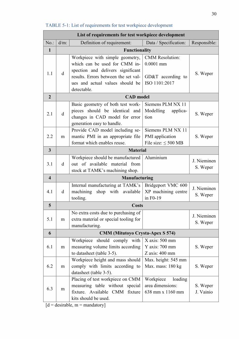
30
TABLE 5-1: List of requirements for test workpiece development
List of requirements for test workpiece development No.: d/m: Definition of requirement: Data / Specification: Responsible:
1 Functionality
1.1 d
Workpiece with simple geometry, which can be used for CMM in-spection and delivers significant results. Errors between the set val-ues and actual values should be detectable.
CMM Resolution: 0.0001 mm GD&T according to ISO 1101:2017
S. Weper
2 CAD model
2.1 d
Basic geometry of both test work-pieces should be identical and changes in CAD model for error generation easy to handle.
Siemens PLM NX 11 Modelling applica-tion
S. Weper
2.2 m Provide CAD model including se-mantic PMI in an appropriate file format which enables reuse.
Siemens PLM NX 11 PMI application File size: ≤ 500 MB
S. Weper
3 Material
3.1 d Workpiece should be manufactured out of available material from stock at TAMK’s machining shop.
Aluminium J. Nieminen
S. Weper
4 Manufacturing
4.1 d Internal manufacturing at TAMK’s machining shop with available tooling.
Bridgeport VMC 600 XP machining centre in F0-19
J. Nieminen S. Weper
5 Costs
5.1 m No extra costs due to purchasing of extra material or special tooling for manufacturing.
J. Nieminen
S. Weper
6 CMM (Mitutoyo Crysta-Apex S 574)
6.1 m Workpiece should comply with measuring volume limits according to datasheet (table 3-5).
X axis: 500 mm Y axis: 700 mm Z axis: 400 mm
S. Weper
6.2 m Workpiece height and mass should comply with limits according to datasheet (table 3-5).
Max. height: 545 mm Max. mass: 180 kg S. Weper
6.3 m
Placing of test workpiece on CMM measuring table without special fixture. Available CMM fixture kits should be used.
Workpiece loading area dimensions: 638 mm x 1160 mm
S. Weper J. Vainio
[d = desirable, m = mandatory]
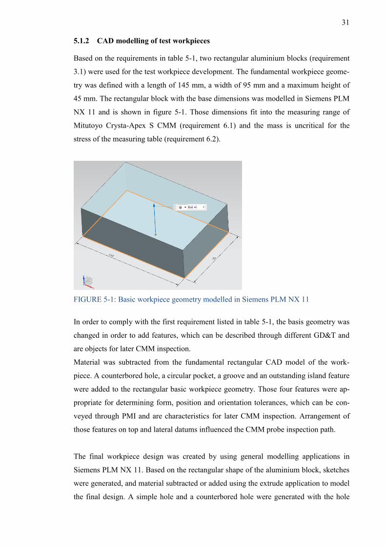
31
5.1.2 CAD modelling of test workpieces
Based on the requirements in table 5-1, two rectangular aluminium blocks (requirement
3.1) were used for the test workpiece development. The fundamental workpiece geome-
try was defined with a length of 145 mm, a width of 95 mm and a maximum height of
45 mm. The rectangular block with the base dimensions was modelled in Siemens PLM
NX 11 and is shown in figure 5-1. Those dimensions fit into the measuring range of
Mitutoyo Crysta-Apex S CMM (requirement 6.1) and the mass is uncritical for the
stress of the measuring table (requirement 6.2).
FIGURE 5-1: Basic workpiece geometry modelled in Siemens PLM NX 11
In order to comply with the first requirement listed in table 5-1, the basis geometry was
changed in order to add features, which can be described through different GD&T and
are objects for later CMM inspection.
Material was subtracted from the fundamental rectangular CAD model of the work-
piece. A counterbored hole, a circular pocket, a groove and an outstanding island feature
were added to the rectangular basic workpiece geometry. Those four features were ap-
propriate for determining form, position and orientation tolerances, which can be con-
veyed through PMI and are characteristics for later CMM inspection. Arrangement of
those features on top and lateral datums influenced the CMM probe inspection path.
The final workpiece design was created by using general modelling applications in
Siemens PLM NX 11. Based on the rectangular shape of the aluminium block, sketches
were generated, and material subtracted or added using the extrude application to model
the final design. A simple hole and a counterbored hole were generated with the hole
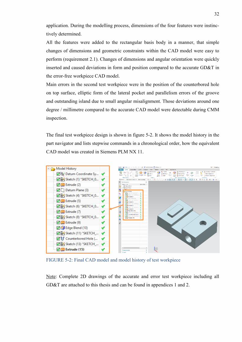
32
application. During the modelling process, dimensions of the four features were instinc-
tively determined.
All the features were added to the rectangular basis body in a manner, that simple
changes of dimensions and geometric constraints within the CAD model were easy to
perform (requirement 2.1). Changes of dimensions and angular orientation were quickly
inserted and caused deviations in form and position compared to the accurate GD&T in
the error-free workpiece CAD model.
Main errors in the second test workpiece were in the position of the counterbored hole
on top surface, elliptic form of the lateral pocket and parallelism errors of the groove
and outstanding island due to small angular misalignment. Those deviations around one
degree / millimetre compared to the accurate CAD model were detectable during CMM
inspection.
The final test workpiece design is shown in figure 5-2. It shows the model history in the
part navigator and lists stepwise commands in a chronological order, how the equivalent
CAD model was created in Siemens PLM NX 11.
FIGURE 5-2: Final CAD model and model history of test workpiece
Note: Complete 2D drawings of the accurate and error test workpiece including all
GD&T are attached to this thesis and can be found in appendices 1 and 2.
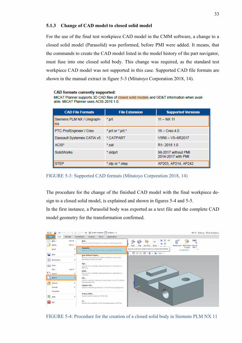
33
5.1.3 Change of CAD model to closed solid model
For the use of the final test workpiece CAD model in the CMM software, a change to a
closed solid model (Parasolid) was performed, before PMI were added. It means, that
the commands to create the CAD model listed in the model history of the part navigator,
must fuse into one closed solid body. This change was required, as the standard test
workpiece CAD model was not supported in this case. Supported CAD file formats are
shown in the manual extract in figure 5-3 (Mitutoyo Corporation 2018, 14).
FIGURE 5-3: Supported CAD formats (Mitutoyo Corporation 2018, 14)
The procedure for the change of the finished CAD model with the final workpiece de-
sign to a closed solid model, is explained and shown in figures 5-4 and 5-5.
In the first instance, a Parasolid body was exported as a text file and the complete CAD
model geometry for the transformation confirmed.
FIGURE 5-4: Procedure for the creation of a closed solid body in Siemens PLM NX 11
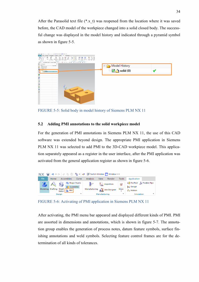
34
After the Parasolid text file (*.x_t) was reopened from the location where it was saved
before, the CAD model of the workpiece changed into a solid closed body. The success-
ful change was displayed in the model history and indicated through a pyramid symbol
as shown in figure 5-5.
FIGURE 5-5: Solid body in model history of Siemens PLM NX 11
5.2 Adding PMI annotations to the solid workpiece model
For the generation of PMI annotations in Siemens PLM NX 11, the use of this CAD
software was extended beyond design. The appropriate PMI application in Siemens
PLM NX 11 was selected to add PMI to the 3D-CAD workpiece model. This applica-
tion separately appeared as a register in the user interface, after the PMI application was
activated from the general application register as shown in figure 5-6.
FIGURE 5-6: Activating of PMI application in Siemens PLM NX 11
After activating, the PMI menu bar appeared and displayed different kinds of PMI. PMI
are assorted in dimensions and annotations, which is shown in figure 5-7. The annota-
tion group enables the generation of process notes, datum feature symbols, surface fin-
ishing annotations and weld symbols. Selecting feature control frames are for the de-
termination of all kinds of tolerances.
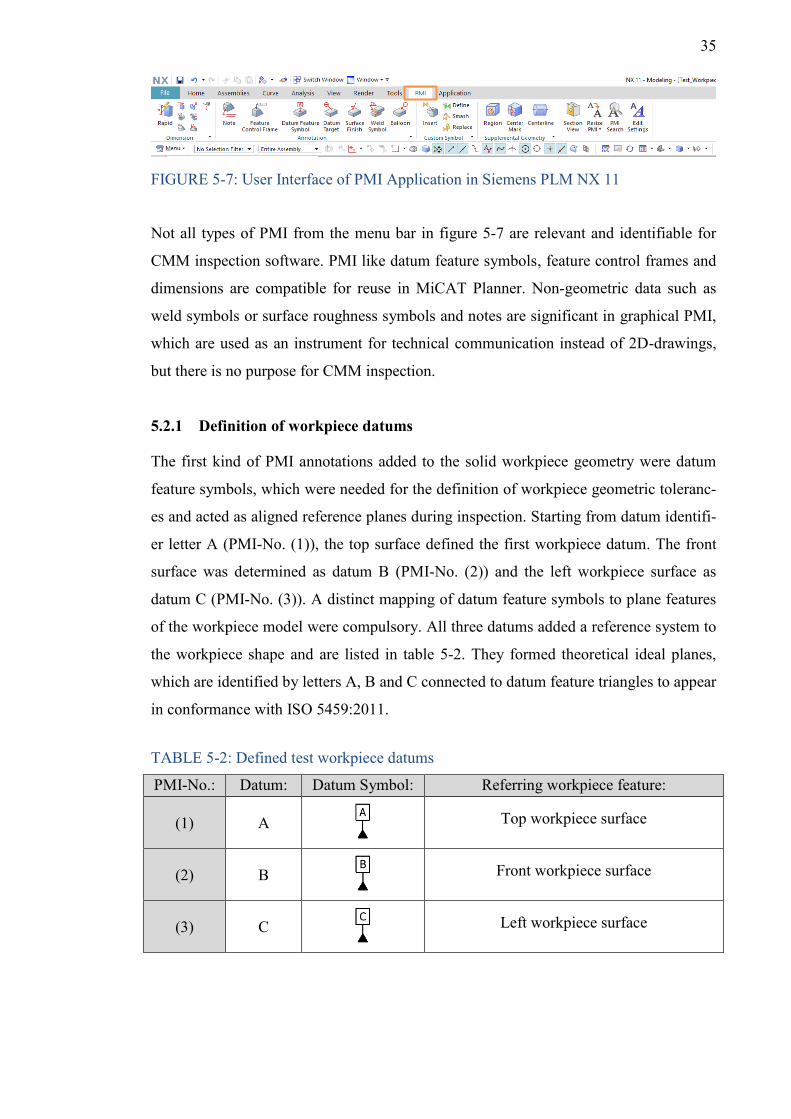
35
FIGURE 5-7: User Interface of PMI Application in Siemens PLM NX 11
Not all types of PMI from the menu bar in figure 5-7 are relevant and identifiable for
CMM inspection software. PMI like datum feature symbols, feature control frames and
dimensions are compatible for reuse in MiCAT Planner. Non-geometric data such as
weld symbols or surface roughness symbols and notes are significant in graphical PMI,
which are used as an instrument for technical communication instead of 2D-drawings,
but there is no purpose for CMM inspection.
5.2.1 Definition of workpiece datums
The first kind of PMI annotations added to the solid workpiece geometry were datum
feature symbols, which were needed for the definition of workpiece geometric toleranc-
es and acted as aligned reference planes during inspection. Starting from datum identifi-
er letter A (PMI-No. (1)), the top surface defined the first workpiece datum. The front
surface was determined as datum B (PMI-No. (2)) and the left workpiece surface as
datum C (PMI-No. (3)). A distinct mapping of datum feature symbols to plane features
of the workpiece model were compulsory. All three datums added a reference system to
the workpiece shape and are listed in table 5-2. They formed theoretical ideal planes,
which are identified by letters A, B and C connected to datum feature triangles to appear
in conformance with ISO 5459:2011.
TABLE 5-2: Defined test workpiece datums
PMI-No.: Datum: Datum Symbol: Referring workpiece feature:
(1) A
Top workpiece surface
(2) B
Front workpiece surface
(3) C
Left workpiece surface
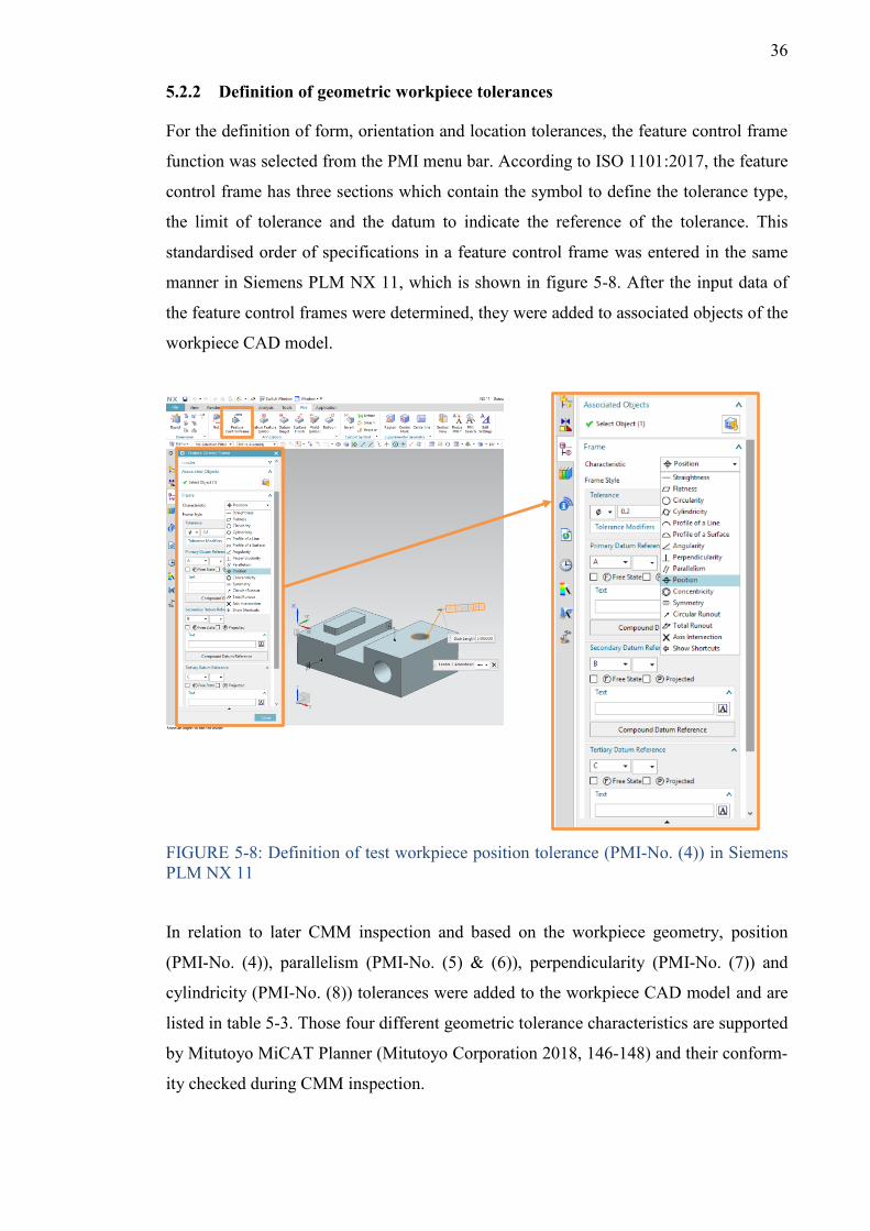
36
5.2.2 Definition of geometric workpiece tolerances
For the definition of form, orientation and location tolerances, the feature control frame
function was selected from the PMI menu bar. According to ISO 1101:2017, the feature
control frame has three sections which contain the symbol to define the tolerance type,
the limit of tolerance and the datum to indicate the reference of the tolerance. This
standardised order of specifications in a feature control frame was entered in the same
manner in Siemens PLM NX 11, which is shown in figure 5-8. After the input data of
the feature control frames were determined, they were added to associated objects of the
workpiece CAD model.
FIGURE 5-8: Definition of test workpiece position tolerance (PMI-No. (4)) in Siemens PLM NX 11
In relation to later CMM inspection and based on the workpiece geometry, position
(PMI-No. (4)), parallelism (PMI-No. (5) & (6)), perpendicularity (PMI-No. (7)) and
cylindricity (PMI-No. (8)) tolerances were added to the workpiece CAD model and are
listed in table 5-3. Those four different geometric tolerance characteristics are supported
by Mitutoyo MiCAT Planner (Mitutoyo Corporation 2018, 146-148) and their conform-
ity checked during CMM inspection.
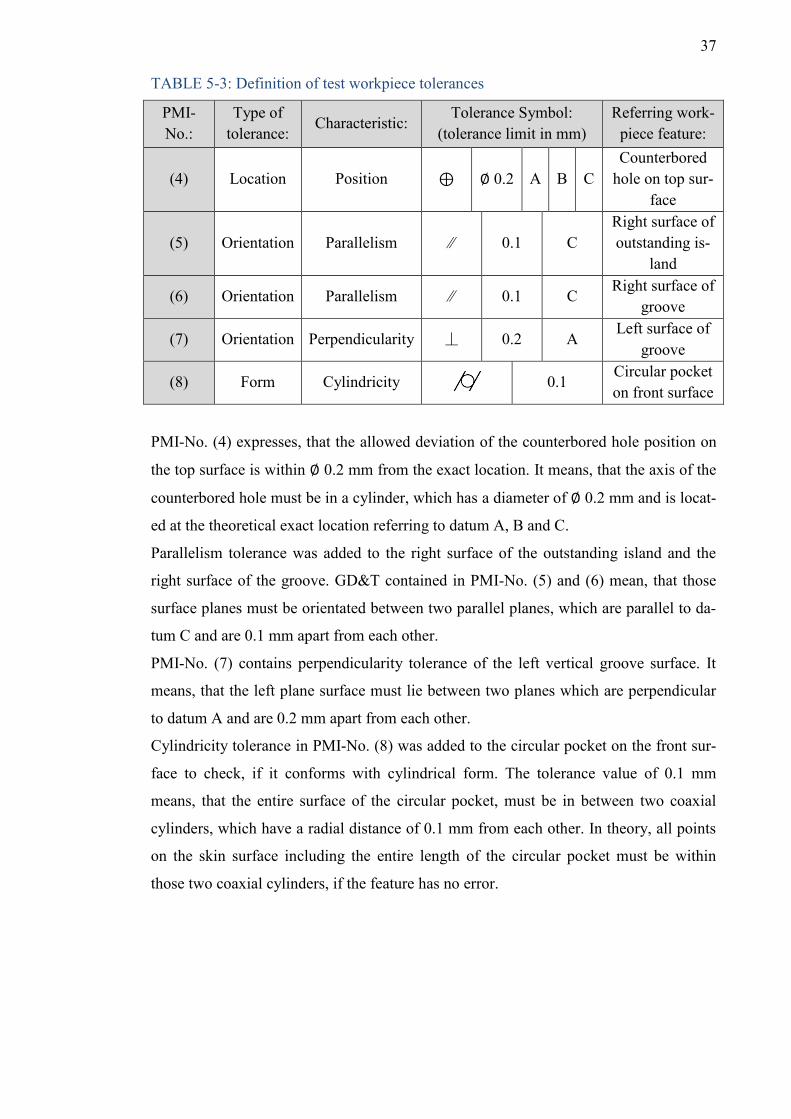
37
TABLE 5-3: Definition of test workpiece tolerances
PMI-No.:
Type of tolerance:
Characteristic: Tolerance Symbol:
(tolerance limit in mm) Referring work-
piece feature:
(4) Location Position ⊕ ∅ 0.2 A B C Counterbored
hole on top sur-face
(5) Orientation Parallelism ∕∕ 0.1 C Right surface of outstanding is-
land
(6) Orientation Parallelism ∕∕ 0.1 C Right surface of
groove
(7) Orientation Perpendicularity ⏊ 0.2 A Left surface of
groove
(8) Form Cylindricity 0.1 Circular pocket on front surface
PMI-No. (4) expresses, that the allowed deviation of the counterbored hole position on
the top surface is within ∅ 0.2 mm from the exact location. It means, that the axis of the
counterbored hole must be in a cylinder, which has a diameter of ∅ 0.2 mm and is locat-
ed at the theoretical exact location referring to datum A, B and C.
Parallelism tolerance was added to the right surface of the outstanding island and the
right surface of the groove. GD&T contained in PMI-No. (5) and (6) mean, that those
surface planes must be orientated between two parallel planes, which are parallel to da-
tum C and are 0.1 mm apart from each other.
PMI-No. (7) contains perpendicularity tolerance of the left vertical groove surface. It
means, that the left plane surface must lie between two planes which are perpendicular
to datum A and are 0.2 mm apart from each other.
Cylindricity tolerance in PMI-No. (8) was added to the circular pocket on the front sur-
face to check, if it conforms with cylindrical form. The tolerance value of 0.1 mm
means, that the entire surface of the circular pocket, must be in between two coaxial
cylinders, which have a radial distance of 0.1 mm from each other. In theory, all points
on the skin surface including the entire length of the circular pocket must be within
those two coaxial cylinders, if the feature has no error.
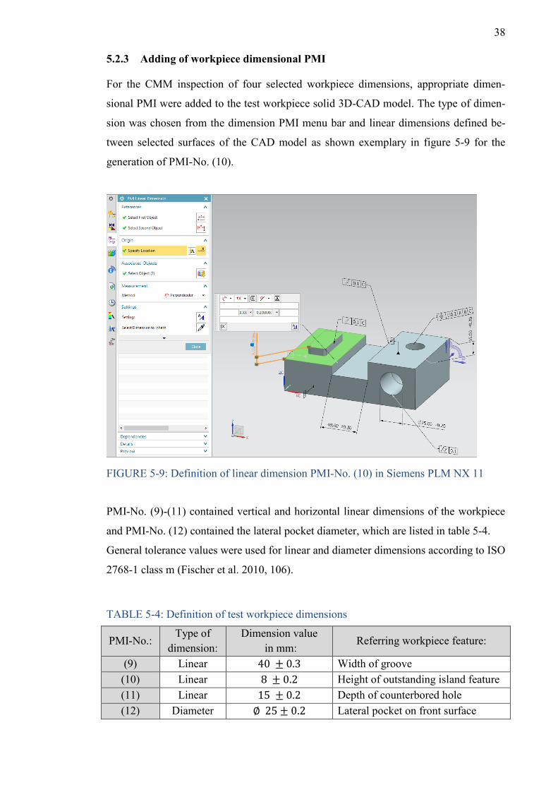
38
5.2.3 Adding of workpiece dimensional PMI
For the CMM inspection of four selected workpiece dimensions, appropriate dimen-
sional PMI were added to the test workpiece solid 3D-CAD model. The type of dimen-
sion was chosen from the dimension PMI menu bar and linear dimensions defined be-
tween selected surfaces of the CAD model as shown exemplary in figure 5-9 for the
generation of PMI-No. (10).
FIGURE 5-9: Definition of linear dimension PMI-No. (10) in Siemens PLM NX 11
PMI-No. (9)-(11) contained vertical and horizontal linear dimensions of the workpiece
and PMI-No. (12) contained the lateral pocket diameter, which are listed in table 5-4.
General tolerance values were used for linear and diameter dimensions according to ISO
2768-1 class m (Fischer et al. 2010, 106).
TABLE 5-4: Definition of test workpiece dimensions
PMI-No.: Type of
dimension: Dimension value
in mm: Referring workpiece feature:
(9) Linear 40 ± 0.3 Width of groove (10) Linear 8 ± 0.2 Height of outstanding island feature (11) Linear 15 ± 0.2 Depth of counterbored hole (12) Diameter ∅ 25 ± 0.2 Lateral pocket on front surface
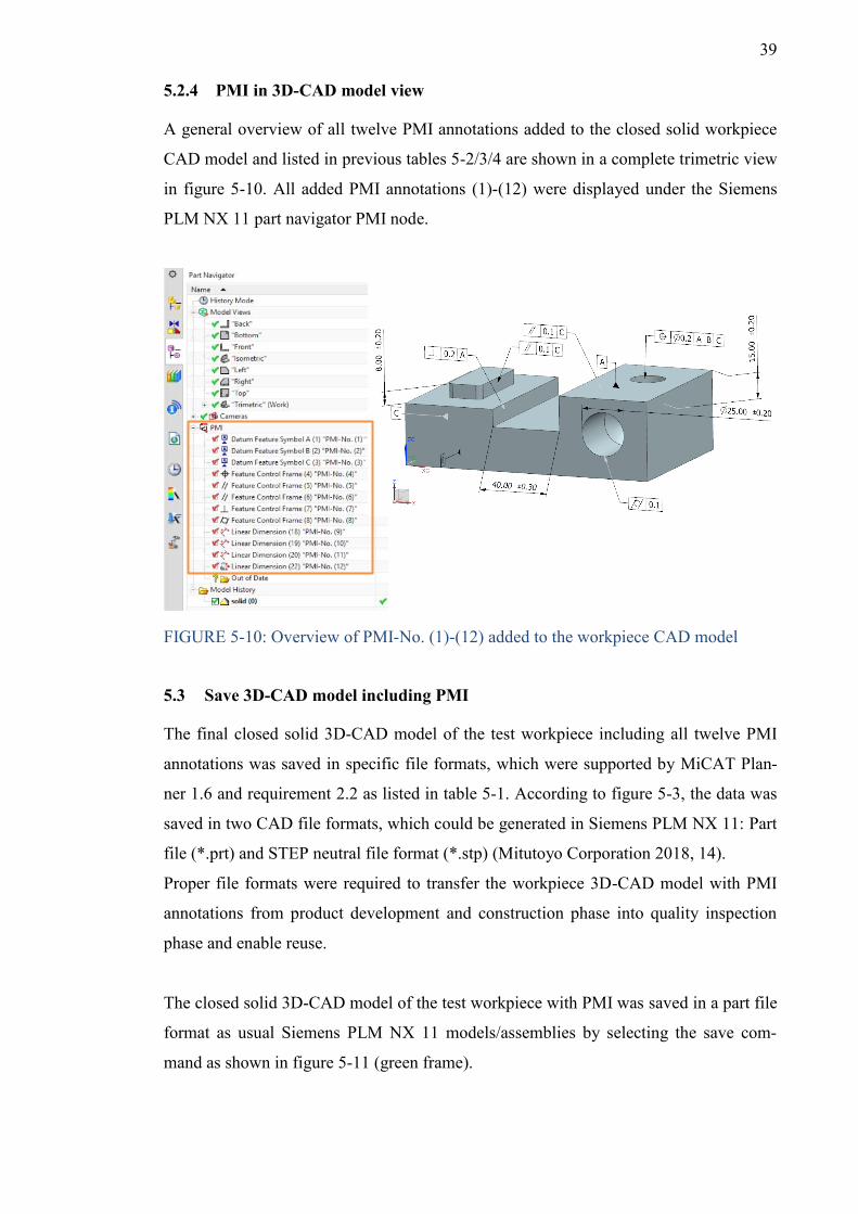
39
5.2.4 PMI in 3D-CAD model view
A general overview of all twelve PMI annotations added to the closed solid workpiece
CAD model and listed in previous tables 5-2/3/4 are shown in a complete trimetric view
in figure 5-10. All added PMI annotations (1)-(12) were displayed under the Siemens
PLM NX 11 part navigator PMI node.
FIGURE 5-10: Overview of PMI-No. (1)-(12) added to the workpiece CAD model
5.3 Save 3D-CAD model including PMI
The final closed solid 3D-CAD model of the test workpiece including all twelve PMI
annotations was saved in specific file formats, which were supported by MiCAT Plan-
ner 1.6 and requirement 2.2 as listed in table 5-1. According to figure 5-3, the data was
saved in two CAD file formats, which could be generated in Siemens PLM NX 11: Part
file (*.prt) and STEP neutral file format (*.stp) (Mitutoyo Corporation 2018, 14).
Proper file formats were required to transfer the workpiece 3D-CAD model with PMI
annotations from product development and construction phase into quality inspection
phase and enable reuse.
The closed solid 3D-CAD model of the test workpiece with PMI was saved in a part file
format as usual Siemens PLM NX 11 models/assemblies by selecting the save com-
mand as shown in figure 5-11 (green frame).
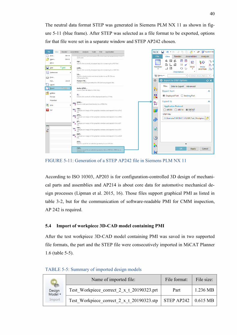
40
The neutral data format STEP was generated in Siemens PLM NX 11 as shown in fig-
ure 5-11 (blue frame). After STEP was selected as a file format to be exported, options
for that file were set in a separate window and STEP AP242 chosen.
FIGURE 5-11: Generation of a STEP AP242 file in Siemens PLM NX 11
According to ISO 10303, AP203 is for configuration-controlled 3D design of mechani-
cal parts and assemblies and AP214 is about core data for automotive mechanical de-
sign processes (Lipman et al. 2015, 16). Those files support graphical PMI as listed in
table 3-2, but for the communication of software-readable PMI for CMM inspection,
AP 242 is required.
5.4 Import of workpiece 3D-CAD model containing PMI
After the test workpiece 3D-CAD model containing PMI was saved in two supported
file formats, the part and the STEP file were consecutively imported in MiCAT Planner
1.6 (table 5-5).
TABLE 5-5: Summary of imported design models
Name of imported file: File format: File size:
Test_Workpiece_correct_2_x_t_20190323.prt Part 1.236 MB
Test_Workpiece_correct_2_x_t_20190323.stp STEP AP242 0.615 MB
*.prt
*.stp
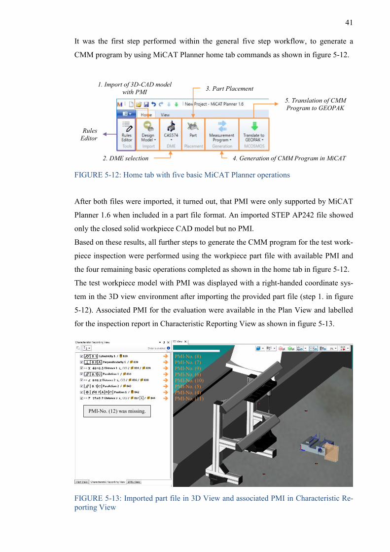
41
It was the first step performed within the general five step workflow, to generate a
CMM program by using MiCAT Planner home tab commands as shown in figure 5-12.
FIGURE 5-12: Home tab with five basic MiCAT Planner operations
After both files were imported, it turned out, that PMI were only supported by MiCAT
Planner 1.6 when included in a part file format. An imported STEP AP242 file showed
only the closed solid workpiece CAD model but no PMI.
Based on these results, all further steps to generate the CMM program for the test work-
piece inspection were performed using the workpiece part file with available PMI and
the four remaining basic operations completed as shown in the home tab in figure 5-12.
The test workpiece model with PMI was displayed with a right-handed coordinate sys-
tem in the 3D view environment after importing the provided part file (step 1. in figure
5-12). Associated PMI for the evaluation were available in the Plan View and labelled
for the inspection report in Characteristic Reporting View as shown in figure 5-13.
FIGURE 5-13: Imported part file in 3D View and associated PMI in Characteristic Re-porting View
1. Import of 3D-CAD model with PMI
2. DME selection
3. Part Placement
4. Generation of CMM Program in MiCAT
5. Translation of CMM Program to GEOPAK
Rules Editor
➔ PMI-No. (8) ➔ PMI-No. (7) ➔ PMI-No. (9) ➔ PMI-No. (6) ➔ PMI-No. (10) ➔ PMI-No. (5) ➔ PMI-No. (4) ➔ PMI-No. (11)
PMI-No. (12) was missing.
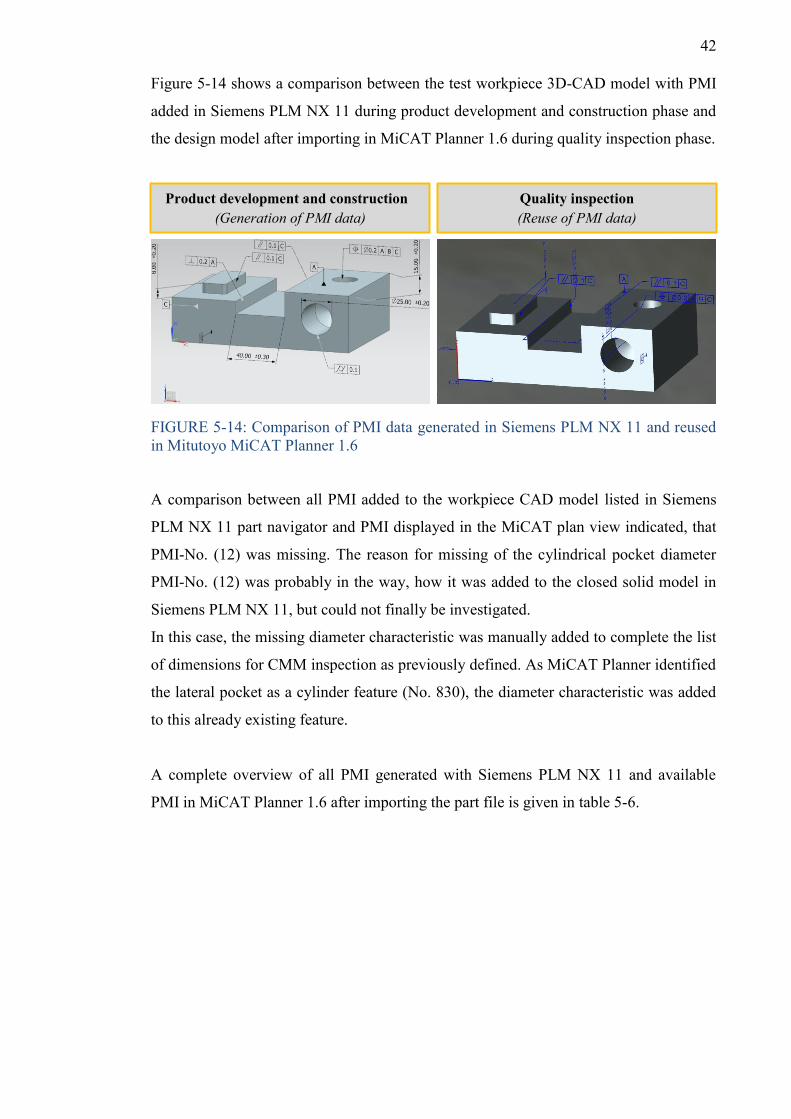
42
Figure 5-14 shows a comparison between the test workpiece 3D-CAD model with PMI
added in Siemens PLM NX 11 during product development and construction phase and
the design model after importing in MiCAT Planner 1.6 during quality inspection phase.
FIGURE 5-14: Comparison of PMI data generated in Siemens PLM NX 11 and reused in Mitutoyo MiCAT Planner 1.6
A comparison between all PMI added to the workpiece CAD model listed in Siemens
PLM NX 11 part navigator and PMI displayed in the MiCAT plan view indicated, that
PMI-No. (12) was missing. The reason for missing of the cylindrical pocket diameter
PMI-No. (12) was probably in the way, how it was added to the closed solid model in
Siemens PLM NX 11, but could not finally be investigated.
In this case, the missing diameter characteristic was manually added to complete the list
of dimensions for CMM inspection as previously defined. As MiCAT Planner identified
the lateral pocket as a cylinder feature (No. 830), the diameter characteristic was added
to this already existing feature.
A complete overview of all PMI generated with Siemens PLM NX 11 and available
PMI in MiCAT Planner 1.6 after importing the part file is given in table 5-6.
Product development and construction (Generation of PMI data)
Quality inspection (Reuse of PMI data)
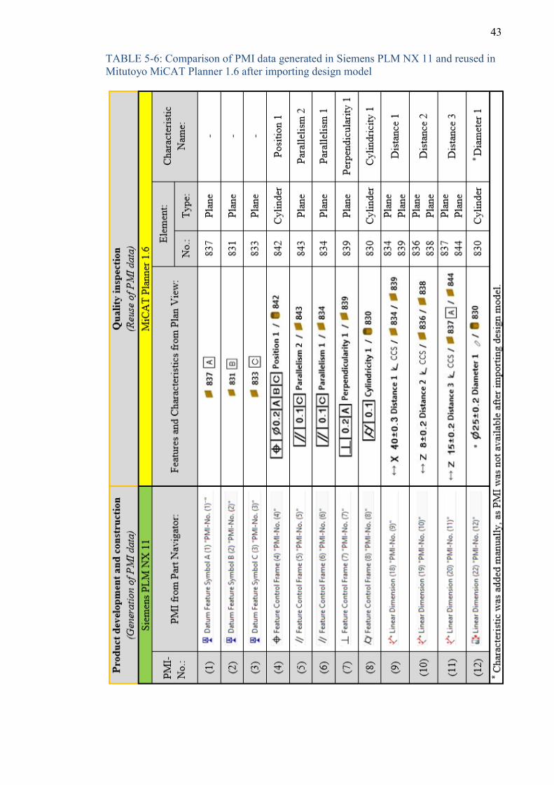
43
TABLE 5-6: Comparison of PMI data generated in Siemens PLM NX 11 and reused in Mitutoyo MiCAT Planner 1.6 after importing design model
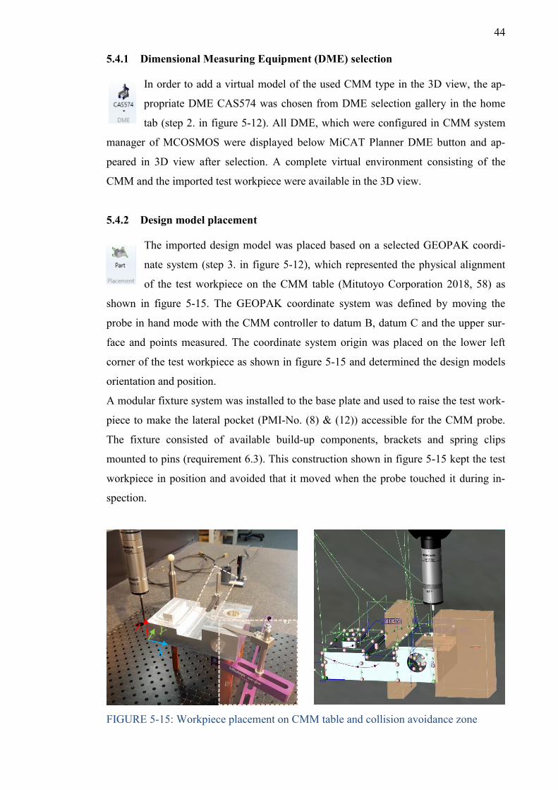
44
5.4.1 Dimensional Measuring Equipment (DME) selection
In order to add a virtual model of the used CMM type in the 3D view, the ap-
propriate DME CAS574 was chosen from DME selection gallery in the home
tab (step 2. in figure 5-12). All DME, which were configured in CMM system
manager of MCOSMOS were displayed below MiCAT Planner DME button and ap-
peared in 3D view after selection. A complete virtual environment consisting of the
CMM and the imported test workpiece were available in the 3D view.
5.4.2 Design model placement
The imported design model was placed based on a selected GEOPAK coordi-
nate system (step 3. in figure 5-12), which represented the physical alignment
of the test workpiece on the CMM table (Mitutoyo Corporation 2018, 58) as
shown in figure 5-15. The GEOPAK coordinate system was defined by moving the
probe in hand mode with the CMM controller to datum B, datum C and the upper sur-
face and points measured. The coordinate system origin was placed on the lower left
corner of the test workpiece as shown in figure 5-15 and determined the design models
orientation and position.
A modular fixture system was installed to the base plate and used to raise the test work-
piece to make the lateral pocket (PMI-No. (8) & (12)) accessible for the CMM probe.
The fixture consisted of available build-up components, brackets and spring clips
mounted to pins (requirement 6.3). This construction shown in figure 5-15 kept the test
workpiece in position and avoided that it moved when the probe touched it during in-
spection.
FIGURE 5-15: Workpiece placement on CMM table and collision avoidance zone
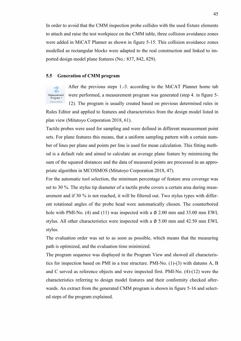
45
In order to avoid that the CMM inspection probe collides with the used fixture elements
to attach and raise the test workpiece on the CMM table, three collision avoidance zones
were added in MiCAT Planner as shown in figure 5-15. This collision avoidance zones
modelled as rectangular blocks were adapted to the real construction and linked to im-
ported design model plane features (No.: 837, 842, 829).
5.5 Generation of CMM program
After the previous steps 1.-3. according to the MiCAT Planner home tab
were performed, a measurement program was generated (step 4. in figure 5-
12). The program is usually created based on previous determined rules in
Rules Editor and applied to features and characteristics from the design model listed in
plan view (Mitutoyo Corporation 2018, 61).
Tactile probes were used for sampling and were defined in different measurement point
sets. For plane features this means, that a uniform sampling pattern with a certain num-
ber of lines per plane and points per line is used for mean calculation. This fitting meth-
od is a default rule and aimed to calculate an average plane feature by minimizing the
sum of the squared distances and the data of measured points are processed in an appro-
priate algorithm in MCOSMOS (Mitutoyo Corporation 2018, 47).
For the automatic tool selection, the minimum percentage of feature area coverage was
set to 30 %. The stylus tip diameter of a tactile probe covers a certain area during meas-
urement and if 30 % is not reached, it will be filtered out. Two stylus types with differ-
ent rotational angles of the probe head were automatically chosen. The counterbored
hole with PMI-No. (4) and (11) was inspected with a ∅ 2.00 mm and 33.00 mm EWL
stylus. All other characteristics were inspected with a ∅ 5.00 mm and 42.50 mm EWL
stylus.
The evaluation order was set to as soon as possible, which means that the measuring
path is optimized, and the evaluation time minimized.
The program sequence was displayed in the Program View and showed all characteris-
tics for inspection based on PMI in a tree structure. PMI-No. (1)-(3) with datums A, B
and C served as reference objects and were inspected first. PMI-No. (4)-(12) were the
characteristics referring to design model features and their conformity checked after-
wards. An extract from the generated CMM program is shown in figure 5-16 and select-
ed steps of the program explained.
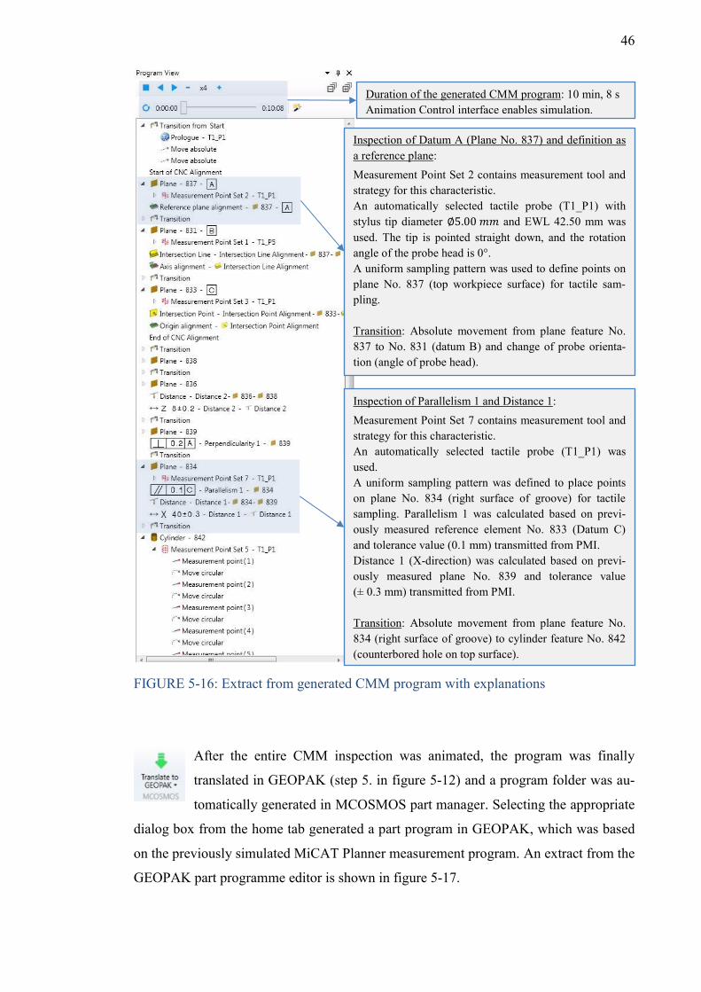
46
FIGURE 5-16: Extract from generated CMM program with explanations
After the entire CMM inspection was animated, the program was finally
translated in GEOPAK (step 5. in figure 5-12) and a program folder was au-
tomatically generated in MCOSMOS part manager. Selecting the appropriate
dialog box from the home tab generated a part program in GEOPAK, which was based
on the previously simulated MiCAT Planner measurement program. An extract from the
GEOPAK part programme editor is shown in figure 5-17.
Inspection of Datum A (Plane No. 837) and definition as a reference plane: Measurement Point Set 2 contains measurement tool and strategy for this characteristic. An automatically selected tactile probe (T1_P1) with stylus tip diameter ∅5.00 𝑚𝑚 and EWL 42.50 mm was used. The tip is pointed straight down, and the rotation angle of the probe head is 0°. A uniform sampling pattern was used to define points on plane No. 837 (top workpiece surface) for tactile sam-pling. Transition: Absolute movement from plane feature No. 837 to No. 831 (datum B) and change of probe orienta-tion (angle of probe head).
Duration of the generated CMM program: 10 min, 8 s Animation Control interface enables simulation.
Inspection of Parallelism 1 and Distance 1: Measurement Point Set 7 contains measurement tool and strategy for this characteristic. An automatically selected tactile probe (T1_P1) was used. A uniform sampling pattern was defined to place points on plane No. 834 (right surface of groove) for tactile sampling. Parallelism 1 was calculated based on previ-ously measured reference element No. 833 (Datum C) and tolerance value (0.1 mm) transmitted from PMI. Distance 1 (X-direction) was calculated based on previ-ously measured plane No. 839 and tolerance value (± 0.3 mm) transmitted from PMI. Transition: Absolute movement from plane feature No. 834 (right surface of groove) to cylinder feature No. 842 (counterbored hole on top surface).
47
FIGURE 5-17: Extract from part program after translating to GEOPAK with explana-tions
The GEOPAK part program (figure 5-17) editor with all listed steps for the CMM pro-
gram execution was automatically generated from the previous MiCAT inputs and
based on the imported design model with PMI. All the program steps in GEOPAK must
be programmed manually without MiCAT Planner, which is time consuming and out-
lined the benefits when PMI data can be reused for inspection at this stage.
5.6 CMM inspection of test workpiece
Both test workpieces were consecutively inspected based on the generated CMM pro-
gram. All characteristics names from characteristic reporting view as listed in table 5-6
were automatically used for the measurement report, generated with MCOSMOS GE-
OPAK module. The errors in the defective workpiece were detected through CMM in-
spection as expected. Even the correct workpiece was not manufactured without errors
and parallelism and position deviations were detected during CMM inspection.
The complete measurement reports of the accurate and error test workpiece CMM in-
spections are attached to this thesis in appendices 5 and 6.
Inspection of Parallelism 1 and Distance 1 as shown and explained in previous figure 5-16.
Inspection of Plane No. 836: Measurement Point Set 9 con-tained the definition of a uniform sampling pattern to place points on plane No. 836 (top surface of outstanding island) for tactile sampling. Mean was the fitting method to calculate the average plane feature No. 836. Distance 2 (Z-direction) was calculated based on previously measured plane No. 838 and tolerance values (± 0.2 mm) transmitted from PMI.
48
6 RESULTS
6.1 Requirements for PMI implementation
PMI generated in product development and construction phase must meet specific needs
of different downstream users (Andre et al. 2002, 5). As the reuse of PMI is relevant for
CMM inspection at TAMK, the following requirements for that process must be consid-
ered.
6.1.1 CAD software
A fundamental requirement for the implementation of PMI is the availability of CAD
software, which enables the generation of semantic PMI through an appropriate MBD
application included in the CAD software package. Currently available CAD software at
TAMK, such as Autodesk Inventor Professional 2018, Dassault Systèmes SolidWorks
2018 and Siemens PLM NX 11 can be used to generate semantic PMI. The PMI appli-
cation in Siemens PLM NX 11 was extensively tested during this thesis work and the
requirement of MBD applications within available CAD software is already met at
TAMK.
Dealing with MBD/PMI applications in available CAD software must be trained and
included in CAD lectures, in order to prepare TAMK staff and students. Besides the
skills to understand, how PMI are added to the CAD model to enable reuse, the aware-
ness of increasing responsibility during product designing process for downstream en-
gineering processes must be raised. A general guideline for the generation of PMI data
in Siemens PLM NX 11 and subsequent reuse for CMM inspection using MiCAT Plan-
ner is given in chapter 5 of this thesis work.
For a complete MBD workflow with integration in MBE networks of industrial partners
(currently not existing in Finland), the functionality of the Siemens PLM NX 11 PMI
application must be expanded to generate and use TDP, which requires an extra licence
(Simons. 2019).
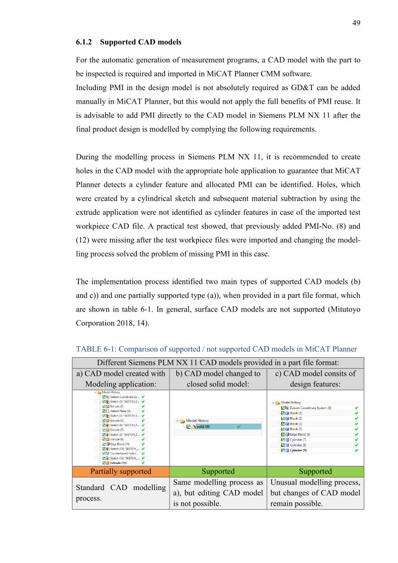
49
6.1.2 Supported CAD models
For the automatic generation of measurement programs, a CAD model with the part to
be inspected is required and imported in MiCAT Planner CMM software.
Including PMI in the design model is not absolutely required as GD&T can be added
manually in MiCAT Planner, but this would not apply the full benefits of PMI reuse. It
is advisable to add PMI directly to the CAD model in Siemens PLM NX 11 after the
final product design is modelled by complying the following requirements.
During the modelling process in Siemens PLM NX 11, it is recommended to create
holes in the CAD model with the appropriate hole application to guarantee that MiCAT
Planner detects a cylinder feature and allocated PMI can be identified. Holes, which
were created by a cylindrical sketch and subsequent material subtraction by using the
extrude application were not identified as cylinder features in case of the imported test
workpiece CAD file. A practical test showed, that previously added PMI-No. (8) and
(12) were missing after the test workpiece files were imported and changing the model-
ling process solved the problem of missing PMI in this case.
The implementation process identified two main types of supported CAD models (b)
and c)) and one partially supported type (a)), when provided in a part file format, which
are shown in table 6-1. In general, surface CAD models are not supported (Mitutoyo
Corporation 2018, 14).
TABLE 6-1: Comparison of supported / not supported CAD models in MiCAT Planner
Different Siemens PLM NX 11 CAD models provided in a part file format: a) CAD model created with
Modeling application: b) CAD model changed to
closed solid model: c) CAD model consits of
design features:
Partially supported Supported Supported
Standard CAD modelling process.
Same modelling process as a), but editing CAD model is not possible.
Unusual modelling process, but changes of CAD model remain possible.
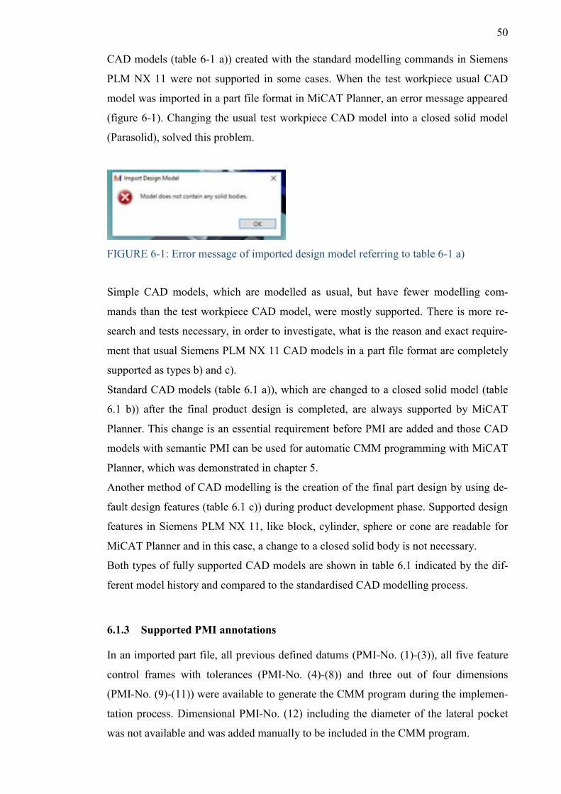
50
CAD models (table 6-1 a)) created with the standard modelling commands in Siemens
PLM NX 11 were not supported in some cases. When the test workpiece usual CAD
model was imported in a part file format in MiCAT Planner, an error message appeared
(figure 6-1). Changing the usual test workpiece CAD model into a closed solid model
(Parasolid), solved this problem.
FIGURE 6-1: Error message of imported design model referring to table 6-1 a)
Simple CAD models, which are modelled as usual, but have fewer modelling com-
mands than the test workpiece CAD model, were mostly supported. There is more re-
search and tests necessary, in order to investigate, what is the reason and exact require-
ment that usual Siemens PLM NX 11 CAD models in a part file format are completely
supported as types b) and c).
Standard CAD models (table 6.1 a)), which are changed to a closed solid model (table
6.1 b)) after the final product design is completed, are always supported by MiCAT
Planner. This change is an essential requirement before PMI are added and those CAD
models with semantic PMI can be used for automatic CMM programming with MiCAT
Planner, which was demonstrated in chapter 5.
Another method of CAD modelling is the creation of the final part design by using de-
fault design features (table 6.1 c)) during product development phase. Supported design
features in Siemens PLM NX 11, like block, cylinder, sphere or cone are readable for
MiCAT Planner and in this case, a change to a closed solid body is not necessary.
Both types of fully supported CAD models are shown in table 6.1 indicated by the dif-
ferent model history and compared to the standardised CAD modelling process.
6.1.3 Supported PMI annotations
In an imported part file, all previous defined datums (PMI-No. (1)-(3)), all five feature
control frames with tolerances (PMI-No. (4)-(8)) and three out of four dimensions
(PMI-No. (9)-(11)) were available to generate the CMM program during the implemen-
tation process. Dimensional PMI-No. (12) including the diameter of the lateral pocket
was not available and was added manually to be included in the CMM program.
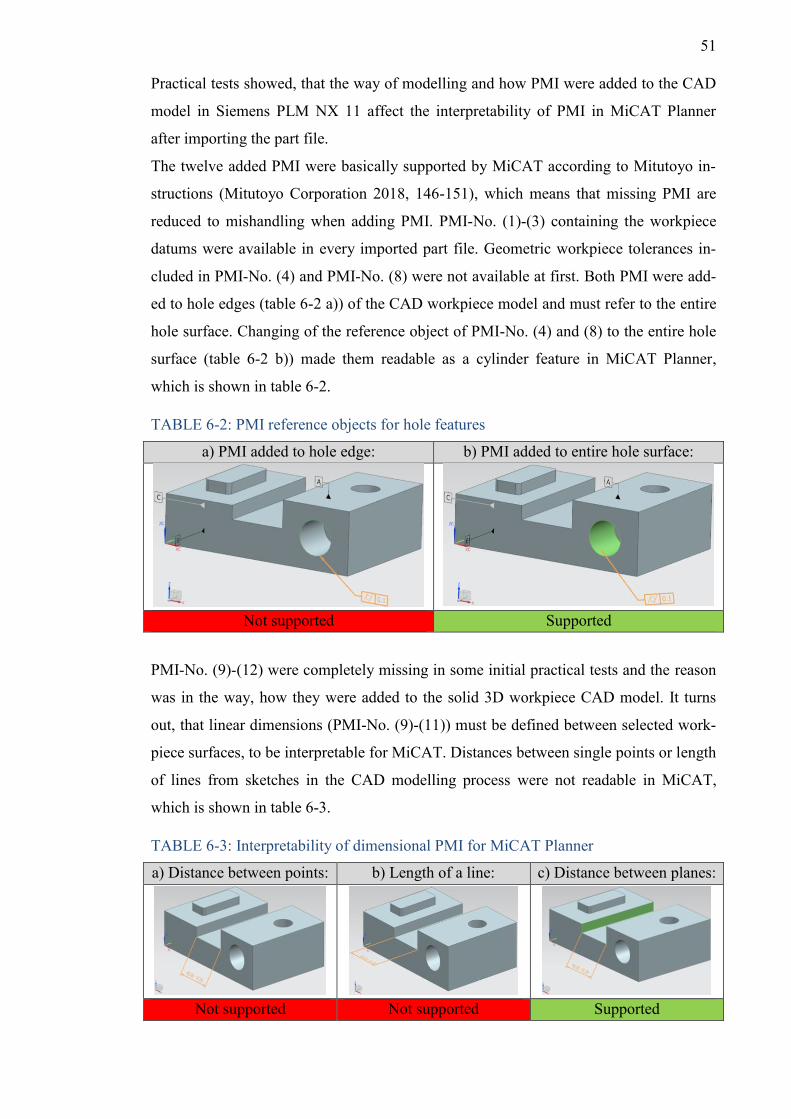
51
Practical tests showed, that the way of modelling and how PMI were added to the CAD
model in Siemens PLM NX 11 affect the interpretability of PMI in MiCAT Planner
after importing the part file.
The twelve added PMI were basically supported by MiCAT according to Mitutoyo in-
structions (Mitutoyo Corporation 2018, 146-151), which means that missing PMI are
reduced to mishandling when adding PMI. PMI-No. (1)-(3) containing the workpiece
datums were available in every imported part file. Geometric workpiece tolerances in-
cluded in PMI-No. (4) and PMI-No. (8) were not available at first. Both PMI were add-
ed to hole edges (table 6-2 a)) of the CAD workpiece model and must refer to the entire
hole surface. Changing of the reference object of PMI-No. (4) and (8) to the entire hole
surface (table 6-2 b)) made them readable as a cylinder feature in MiCAT Planner,
which is shown in table 6-2.
TABLE 6-2: PMI reference objects for hole features
a) PMI added to hole edge: b) PMI added to entire hole surface:
Not supported Supported
PMI-No. (9)-(12) were completely missing in some initial practical tests and the reason
was in the way, how they were added to the solid 3D workpiece CAD model. It turns
out, that linear dimensions (PMI-No. (9)-(11)) must be defined between selected work-
piece surfaces, to be interpretable for MiCAT. Distances between single points or length
of lines from sketches in the CAD modelling process were not readable in MiCAT,
which is shown in table 6-3.
TABLE 6-3: Interpretability of dimensional PMI for MiCAT Planner
a) Distance between points: b) Length of a line: c) Distance between planes:
Not supported Not supported Supported
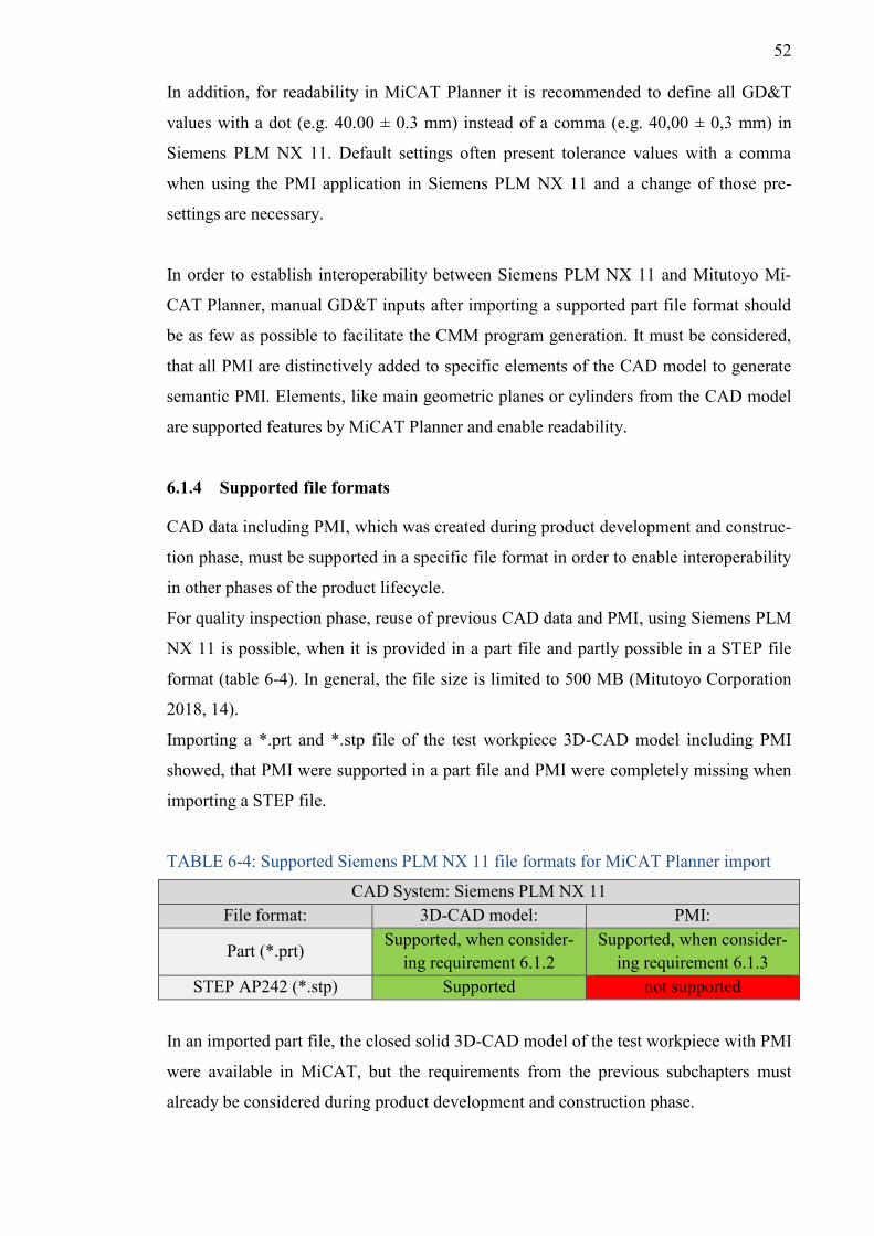
52
In addition, for readability in MiCAT Planner it is recommended to define all GD&T
values with a dot (e.g. 40.00 ± 0.3 mm) instead of a comma (e.g. 40,00 ± 0,3 mm) in
Siemens PLM NX 11. Default settings often present tolerance values with a comma
when using the PMI application in Siemens PLM NX 11 and a change of those pre-
settings are necessary.
In order to establish interoperability between Siemens PLM NX 11 and Mitutoyo Mi-
CAT Planner, manual GD&T inputs after importing a supported part file format should
be as few as possible to facilitate the CMM program generation. It must be considered,
that all PMI are distinctively added to specific elements of the CAD model to generate
semantic PMI. Elements, like main geometric planes or cylinders from the CAD model
are supported features by MiCAT Planner and enable readability.
6.1.4 Supported file formats
CAD data including PMI, which was created during product development and construc-
tion phase, must be supported in a specific file format in order to enable interoperability
in other phases of the product lifecycle.
For quality inspection phase, reuse of previous CAD data and PMI, using Siemens PLM
NX 11 is possible, when it is provided in a part file and partly possible in a STEP file
format (table 6-4). In general, the file size is limited to 500 MB (Mitutoyo Corporation
2018, 14).
Importing a *.prt and *.stp file of the test workpiece 3D-CAD model including PMI
showed, that PMI were supported in a part file and PMI were completely missing when
importing a STEP file.
TABLE 6-4: Supported Siemens PLM NX 11 file formats for MiCAT Planner import
CAD System: Siemens PLM NX 11 File format: 3D-CAD model: PMI:
Part (*.prt) Supported, when consider-
ing requirement 6.1.2 Supported, when consider-
ing requirement 6.1.3 STEP AP242 (*.stp) Supported not supported
In an imported part file, the closed solid 3D-CAD model of the test workpiece with PMI
were available in MiCAT, but the requirements from the previous subchapters must
already be considered during product development and construction phase.
53
All three imported STEP file formats (AP203, AP214, AP242) only showed the solid
workpiece 3D-CAD model in 3D view and none of PMI-No. (1)-(12) appeared in Mi-
CAT Planner Plan View after importing the test workpiece STEP files. In this case,
GD&T for inspection must be added manually. MiCAT Planner version 1.6 currently
does not support STEP files with PMI (Vainio. 2019). A smooth transition between a
provided STEP file for reuse in CMM inspection is not possible without rework.
There is no significant time benefit for CMM program generation, when all GD&T for
inspection extracted from a 2D drawing or CAD software must be added manually to
the design model first. STEP file format will be supported in future MiCAT software
releases and will become more important as a standard methodology for describing
product data throughout a product lifecycle (Lipman et al. 2015, 16). According to ISO
10303-242:2014 (table 3-2), STEP AP242 is the established file format, which is usual-
ly used for downstream applications and can easily be saved in Siemens PLM NX 11. It
is related to MiCAT Planner software, that PMI are not supported in STEP file formats.
In order to facilitate CMM program generation based on PMI at TAMK, it is currently
required to save a supported CAD model with PMI in a part file format in Siemens
PLM NX 11. Knowledge about a dedicated part file format must be shared with indus-
trial partners in case CMM inspection tasks are performed at TAMK and a single CAD
file with PMI of the part for inspection must be provided beforehand.
6.1.5 CMM software environment
Besides the basic need for Mitutoyo MiCAT Planner software to support CAD-models
with PMI, the software Mitutoyo MCOSMOS version v4.2.R3 or later must be available
(Mitutoyo Corporation 2018, 13). As the measurement program generated in MiCAT is
finally translated to GEOPAK module of MCOSMOS, it is an essential requirement,
that this software is already installed before MiCAT Planner is added to the CMM soft-
ware environment at TAMK. MCOSMOS v.4.1.R1 is currently installed on CAS574
work station PC at TAMK and must be updated. The CMM software environment must
be complemented by MiCAT Planner, as this software package is mandatory to utilise
PMI data for inspection.
54
6.2 Benefits of PMI implementation
Three main examined benefits are explained in the following subsections.
6.2.1 CMM programs
The CMM program generation based on PMI with MiCAT Planner is even possible for
less experienced CMM users, if certain rules are pre-set within the Rules Editor by ex-
perienced users (e.g. sampling pattern and number of measurement points). This can be
a benefit for students at TAMK, which have less experience on CMM programming and
combines future orientated use of PMI data as part of MBD workflows. Intuitive han-
dling is enabled through a clearly arranged user interface and the user is guided through
five main steps in the home tab, which makes the CMM program generation easy.
Compared to CMM programming using Mitutoyo MCOSMOS software only, an auto-
matic optimization of the entire CMM inspection process is possible. Manual inputs in
MCOSMOS and the manual generated measurement program might be inefficient in
terms of movement and CMM probe path. PMI data processing in MiCAT supports to
minimise the measurement path and the number of probe orientation and tool changes
during inspection processes (Mitutoyo Corporation 2018, 11). This clearly reduces
CMM programming time and the part inspection is performed in the least amount of
time. Proper tools for the inspection process can be chosen automatically, e.g. based on
rules for the minimum percentage of feature area coverage.
Different CMM programmer skills can cause variations in measurement program gener-
ation and the MiCAT Rules Editor function establishes uniform measurement guide-
lines and equal measuring practices for parts being inspected on the CMM (Mitutoyo
America Corporation 2016, 4).
Integrated collision detection avoids that probes collide during inspection process.
It is advantageous, that the generated CMM programs can be simulated in a 3D view
with a virtual CMM inspecting the imported design model, before executing with GE-
OPAK. This offline measurement program animation indicates inspection paths/points
directly on the design model and facilitates to identify problems and insert manual user
specific settings.
6.2.2 Increase of productivity
PMI data, which was generated in product development and construction phase can be
reused in quality inspection, which increases the level of automation. A single CAD file
with inspection characteristics contained in PMI increases CMM productivity. This is
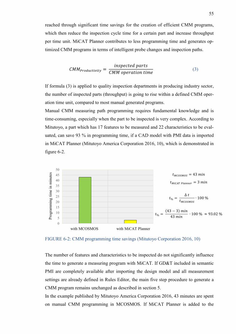
55
reached through significant time savings for the creation of efficient CMM programs,
which then reduce the inspection cycle time for a certain part and increase throughput
per time unit. MiCAT Planner contributes to less programming time and generates op-
timized CMM programs in terms of intelligent probe changes and inspection paths.
𝐶𝑀𝑀𝑃𝑟𝑜𝑑𝑢𝑐𝑡𝑖𝑣𝑖𝑡𝑦 = 𝑖𝑛𝑠𝑝𝑒𝑐𝑡𝑒𝑑 𝑝𝑎𝑟𝑡𝑠
𝐶𝑀𝑀 𝑜𝑝𝑒𝑟𝑎𝑡𝑖𝑜𝑛 𝑡𝑖𝑚𝑒 (3)
If formula (3) is applied to quality inspection departments in producing industry sector,
the number of inspected parts (throughput) is going to rise within a defined CMM oper-
ation time unit, compared to most manual generated programs.
Manual CMM measuring path programming requires fundamental knowledge and is
time-consuming, especially when the part to be inspected is very complex. According to
Mitutoyo, a part which has 17 features to be measured and 22 characteristics to be eval-
uated, can save 93 % in programming time, if a CAD model with PMI data is imported
in MiCAT Planner (Mitutoyo America Corporation 2016, 10), which is demonstrated in
figure 6-2.
FIGURE 6-2: CMM programming time savings (Mitutoyo Corporation 2016, 10)
The number of features and characteristics to be inspected do not significantly influence
the time to generate a measuring program with MiCAT. If GD&T included in semantic
PMI are completely available after importing the design model and all measurement
settings are already defined in Rules Editor, the main five step procedure to generate a
CMM program remains unchanged as described in section 5.
In the example published by Mitutoyo America Corporation 2016, 43 minutes are spent
on manual CMM programming in MCOSMOS. If MiCAT Planner is added to the
05
101520253035404550
Prog
ram
min
g tim
e in
min
utes
with MiCAT Plannerwith MCOSMOS
𝑡𝑀𝐶𝑂𝑆𝑀𝑂𝑆 = 43 𝑚𝑖𝑛
𝑡𝑀𝑖𝐶𝐴𝑇 𝑃𝑙𝑎𝑛𝑛𝑒𝑟 = 3 𝑚𝑖𝑛
𝑡% = ∆ 𝑡
𝑡𝑀𝐶𝑂𝑆𝑀𝑂𝑆∙ 100 %
𝑡% = (43 − 3) 𝑚𝑖𝑛
43 𝑚𝑖𝑛 ∙ 100 % ≈ 93.02 %
56
MCOSMOS software environment, three minutes are needed to generate the CMM pro-
gram. The time specifications in this commercial example were not critical evaluated
and verified in a simultaneous practical test during this thesis work, but it turns out the
set-up time savings during quality inspection phase. Compared to manual generated
CMM programs, the benefits of less programming work and effort in MiCAT Planner
can be confirmed. This causes increasing productivity, which is an important benefit for
PMI implementation, but more related to industry.
6.2.3 Reducing errors
Importing a 3D-CAD model with PMI reduces GD&T translation errors from a 2D
drawing, when a CMM program is generated. The reading and interpretation of 2D
drawings can cause misunderstanding within technical communication, e.g. if there are
not enough projection views to correctly interpret the drawing (Bijnens et al. 2018,
310). It requires experience to read complex 2D drawings and there is no need for man-
ual extraction of GD&T from a drawing, when semantic PMI are directly imported in
MiCAT Planner to generate a CMM program. The risk of ambiguity and faulty CMM
programs because of incomprehensible design intent is reduced. Up-to-dateness of de-
rived 2D drawings must be managed and deviations in revisions causes error. 2D draw-
ings as a source of errors can cause rework in context with CMM inspection, which has
an impact on internal quality costs.
6.3 Risks of PMI implementation
Three main examined risks of PMI implementation are explained in the following sub-
sections.
6.3.1 Dependence on CAD systems
As Mitutoyo MiCAT Planner is currently not supporting PMI included in STEP files, a
part-file format from a dedicated CAD system must be imported in order to use the ben-
efits of PMI data according to the previous chapter for CMM inspection at TAMK.
This causes dependency on CAD systems and always requires, that the CMM software
supports appropriate part-files with PMI. Updated CMM software releases can restrict
the use of part-files from certain CAD systems, which interrupts the PMI data transfer
chain. Different stakeholder are completely dependent on the 3D model and are locked
in to the ecosystem of the CAD vendor (Bijnens et al. 2018, 314).
57
This dependence on specific CAD systems is expanded to external industrial inspection
orders at TAMK, as PMI in neutral file formats (STEP AP242) are currently not sup-
ported by MiCAT Planner 1.6.
Furthermore, the latest release of MiCAT Planner only supports part files from Siemens
PLM NX version 11 and Dassault Systèmes SolidWorks versions 2014-2017 with PMI
(Mitutoyo Corporation 2018, 14). This causes dependence on certain versions of CAD
software and is not conforming with the latest released versions. For example, Solid-
Works 2018 at TAMK cannot be used, as only previous versions are supported. If
TAMK is going to adapt already available Siemens PLM NX 12, part files with PMI
will not be supported by MiCAT Planner 1.6. If possible, saving those part files in an
older version can solve this problem for Siemens PLM NX 12 or Dassault Systèmes
2018 SolidWorks CAD models. According to Mitutoyo Corporation 2018, Autodesk
Inventor 2018 CAD file formats are not supported in MiCAT Planner.
Those risks in connection with the dependence on certain CAD systems and specified
versions remain existing, as long as STEP AP242 neutral files with PMI, which can be
generated in any CAD system, are not completely supported by MiCAT Planner.
6.3.2 CAD models
Only CAD models, which contain closed solid bodies (table 6-1 b)) or consist of design
features (table 6-1 c)) are completely supported by MiCAT Planner, when imported in a
Siemens PLM NX 11 part file format. This requires changes in the CAD modelling pro-
cess in order to create supported design models for inspection and deviates from com-
mon practices.
When creating closed solid bodies (table 6-1 b)), the CAD modelling process remains
the same as usual by using standard modelling commands. After conversion to a closed
solid body, single commands for the CAD model creation are not available in the model
history of NX part navigator anymore and this hinders to edit the model parameters. In
case of changes, the coexistence of a part file without a closed solid body structure is
necessary and must be changed to a closed solid body after editing again.
If the CAD modelling is created by supported design features (table 6-1 c)), geometrical
changes remain possible, but this is a complicated and time-consuming way of model-
ling and differs substantially from common practices.
Both kinds of supported CAD models are adverse in terms of modelling process during
product development and construction phase. This problem can be solved, if STEP
58
AP242 files are supported. The modelling process and the adding of PMI to the 3D-
CAD model is done as usual and must finally be saved in a STEP file format.
6.3.3 Compatibility between CAD software and CMM software
Practical tests during this thesis work outlined deficient compatibility between Siemens
PLM NX 11 and MiCAT Planner 1.6. In general, PMI added to a closed solid 3D-CAD
model in Siemens PLM NX 11 can be used to generate CMM inspection programs in
MiCAT Planner, which was proven in the previous chapter 5.
The used CAD software and corresponding part files are supported by MiCAT Planner
(Mitutoyo Corporation 2018, 14), but the modelling process and the features to which
PMI are added, have significant influence on the availability in MiCAT Planner. There
is no information in the manual, how the CAD model must be configured in order to
ensure proper reuse in MiCAT Planner and general requirements were identified by trial
and error method during several import attempts. When PMI were missing, changing
the reference elements in the CAD model to supported geometrical features (e.g. planes,
cylinders) often effectuated availability and minimized deviations between generated
PMI and displayed PMI in MiCAT Planner.
59
7 CONCLUSION AND OUTLOOK
A practical implementation process included in this thesis showed, that semantic PMI
contained in a single CAD file and generated during product development and construc-
tion phase can be reused for CMM inspection at TAMK, if certain requirements are met.
The main results summarised:
• The use of PMI for CMM inspection is possible at TAMK, but more requirements in
terms of software and hardware are necessary to implement complete MBD work-
flows.
• MBD is not widely utilized besides automotive and aerospace industry. The use of
PMI data in manufacturing and inspection processes is still evolving.
• Designing engineers will face prescient modelling work and increasing responsibil-
ity during product development and construction phase, when PMI data is used in
different downstream engineering processes.
• Currently, only Siemens PLM NX 11 CAD files with PMI are supported by MiCAT
Planner, when provided in a part file format.
• The availability of the design model is dependent on the way, how the CAD model
was generated. Standard modelling methods must be changed, in order to conform
with readability in MiCAT Planner. Two identified methods enable reliable availa-
bility of imported design models in a part file format in MiCAT Planner:
- A closed solid body must be created, and PMI added afterwards.
- The CAD model must consist of supported design features.
• PMI must always refer to certain CAD model objects, like planes or cylinders in
order to enable clear mapping and readability of features in MiCAT Planner.
• Use of PMI / MBD applications in CAD systems must be taught at TAMK.
• PMI included in neutral STEP AP242 files are not yet supported in MiCAT Planner.
There is the potential risk of dependency on certain CAD systems and versions.
STEP files could solve analysed risks and will support included PMI in the future.
• If the CAD model and complete PMI are available, MiCAT Planner facilitates the
CMM program generation, saves time and reduces the risk of errors, as 2D drawings
are not necessary anymore. Less experienced CMM users can generate optimized
CMM programs.
60
This thesis was focused on the generation of PMI data in Siemens PLM NX 11 and re-
use in Mitutoyo MiCAT Planner 1.6 software for the inspection of a simple test work-
piece using Mitutoyo Crysta-Apex S 574 CMM. As MiCAT Planner was not available
at TAMK during processing time of this thesis work, the possibilities for extensive test-
ing of imported Siemens PLM NX 11 design models with PMI were limited. In order to
confirm the investigated results and identify additional requirements, further CAD mod-
els by considering different modelling strategies and added PMI must be imported in
MiCAT Planner.
The identified compatibility problems and disappearance of PMI data only referred to
data exchange between those two software applications and to generalize this identified
risk, potentially tests with other CAD (e.g. Dassault Systèmes SolidWorks) and CMM
software (e.g. Zeiss Calypso) must be done.
Practical tests showed, that there are improvements in different software applications
necessary, in order to guarantee smooth MBD workflows. Some PMI were missing and
manual adding to imported design models must be reduced, to achieve significant pro-
gramming time savings and increase the level of automation. A better collaboration be-
tween different CAD systems and CMM software is needed. It must be investigated in
further tests, how the MBD/PMI application in the CAD software and the imported files
in the CMM software can guarantee less PMI data losses, that the amount of manual
work to create CMM programs can be reduced and the benefits of PMI more efficiently
used.
Especially the use of PMI in neutral data formats, like STEP AP 242 in CMM software
could reduce current dependency on certain CAD systems and could improve interoper-
ability between different software packages. STEP AP 242 files could effectuate in-
creasing flexibility in terms of data exchange, e.g. for external CMM inspection tasks
from industry, without dependence on certain CAD systems and versions.
To move from model centric workflows towards an MBD workflows requires more
research and use of PMI in other downstream processes. This thesis focused on the re-
use of PMI in quality inspection phase using CMM and it must be investigated, how
PMI can be used for manufacturing processes at TAMK. Connecting CAD-FEA-CAM-
CMM processes with the use of PMI would fully implement MBD workflows at
TAMK.
Besides, this thesis work was completely focusing on machine-readable PMI for CMM
software and significance of graphical PMI when moving towards an MBD workflow
61
was not analysed. Graphical PMI are important in context with MBD, as annotated 3D-
CAD models replace 2D drawings and change the way of technical communication.
The workpiece, which was used for the implementation process during this thesis has a
simple geometry, which is not comparable to many products for CMM inspection in
industry. It was an appropriate reference object to identify general requirements for the
use of PMI at TAMK. In many cases, the quality of assemblies is checked on CMM and
it is currently unclear, if the requirements for complex assemblies are the same. The
modelling process in Siemens PLM NX 11 is more complex, but the adding of PMI
annotations remains the same. Importing an assembly file with PMI in MiCAT Planner
was not tested.
It is expected, that the functionality of MiCAT Planner will expand in coming software
releases. For example, CMM inspection of a workpiece surface roughness based on
non-geometric PMI data (surface roughness symbols) might become possible.
Finally, the implementation process in this thesis act as a guideline and can be complet-
ed for CMM inspection based on PMI after MiCAT Planner is available at TAMK.
The use of PMI as part of MBD is currently not widely implemented in industry and
still evolving, but has a high potential and will achieve increasing significance in the
future.
62
REFERENCES
Andre, P. & Sortio, R. 2002. Product Manufacturing Information (PMI) in 3D models: A basis for collaborative engineering in Product Creation Process (PCP). Read on 26.02.2019. http://citeseerx.ist.psu.edu/viewdoc/download?doi=10.1.1.4.2814&rep=rep1&type=pdf. Bijnens, J. & Cheshire, D. 2018. The Current State of Model Based Definition. Com-puter-Aided Design & Applications 16 (2), 308–317. Bijnens, J., Kellens, K. & Cheshire, D. 2018. Accuracy of geometry data exchange us-ing STEP AP242. Procedia CIRP 78 (2018), 219-224. Boy, J., Rosché, P., Paff, E., Fischer, B., Ranger, T., Yates, S., Hendrix, T., Briggs, T. 2014. Recommended Practices for the Representation and Presentation of Product Man-ufacturing Information (PMI) (AP242) – version 4.0, CAx-Implementor Forum. Cicconi, P., Raffaeli, R. & Germani, M. 2016. An approach to support model based def-inition by PMI annotations. Computer-Aided Design & Applications 14 (4), 526-534. Dassault Systèmes. 2014. Improve Quality, Reduce Costs, and Increase Efficiency with Model-Based Definition (White Paper). Read on 10.03.2019. https://www.solidworks.com/sw/docs/Model-Based-Definition-WP-6.pdf. Fischer, U., Gomeringer, R., Heinzler, M., Kilgus, R., Näher, F., Oesterle, S., Paetzold, H., Stephan, A. 2011. Tabellenbuch Metall. Haan-Gruiten: 45. Auflage, Verlag Europa-Lehrmittel. Herron, J. B. 2013. Re-Use Your CAD. The Model-Based CAD Handbook. Action En-gineering LLC. Herron, J. B. 2016. What MBD really looks like. Action Engineering LLC. Read on 13.03.2019. https://www.action-engineering.com/wp-content/uploads/What-MBD-Really-Looks-Like.pdf. Laaksonen, T., Nieminen, J., Pulkkinen, A., Rapinoja, J-P., Simons, J., Uski, P., Salmi, H. & Vainionpää, M. 2016. Malliperustaisen tuotemäärittelyn (MBD) mahdollisuudet. METSTA ry, Teknologiateollisuus ry ja SMACC Raportti. Lipman, R. & Lubell, J. 2015. Conformance checking of PMI representation in CAD model STEP data exchange files. Computer-Aided Design 66 (2015), 14–23. MIL-STD-31000A. 2013. TECHNICAL DATA PACKAGES. Read on 03.04.2019. Requires download. http://everyspec.com/MIL-STD/MIL-STD-10000-and-Up/MIL-STD-31000A_45888/ Mitutoyo America Corporation. 2015. Crysta-Apex S Series coordinate measuring ma-chine. Read on 14.03.2019. https://www.mitutoyo.com/wp-content/uploads/2013/01/2097_CRYSTA_ApexS.pdf.
63
Mitutoyo America Corporation. 2016. MiCAT Planner automatic part program genera-tion. Read on 14.03.2019. https://www.mitutoyo.com/wp-content/uploads/2015/04/MiCAT_Planner.pdf. Mitutoyo Corporation, Mitutoyo Europe GmbH. 2018. MiCAT Planner Training Manu-al Version 1.6. (No. TD-AT-0004). Proto Labs, Inc. 2017. What is Product Manufacturing Information (PMI)? Read on 27.02.2019. https://www.protolabs.com/resources/blog/what-is-product-manufacturing-information-pmi/. Quintana, V., Rivest, L., Pellerin, R., Venne, F. & Kheddouci, F. 2010. Will Model-based Definition replace engineering drawings throughout the product lifecycle? A global perspective from aerospace industry. Computers in Industry 61 (5), 497–508. Quintana, V., Rivest, L., Pellerin, R. & Kheddouci, F. 2012. Re-engineering the Engi-neering Change Management process for a drawing-less environment. Computers in Industry 63 (1), 79–90. Ramesh, M. 2017. Model-Based Definition (MBD) eBook. Version J8216–MBD–EN–0117. PTC Inc. (PTC). Ricci, F., Bedolla, J-S., Gomez, J-M. & Chiabert, P. 2014. PMI: a PLM Approach for the Management of Geometrical and Dimensional Controls in Modern Industries. Com-puter-Aided Design & Applications 11 (S1), 36–43. Ruemler, S-P., Zimmerman, K-E., Hartman, N-W., Hedberg, T. & Feeny, A-B. 2017. Promoting Model-Based Definition to Establish a Complete Product Definition. Journal of Manufacturing Science and Engineering 139 (5), 1-7. SFS-ISO 16792. 2015. Technical product documentation. Digital product definition data practices. Helsinki: Suomen Standardisoimisliitto SFS ry. Read on 27.02.2019. Requires access right. https://online-sfs-fi.libproxy.tuni.fi/en/index/ tuotteet/SFS/ISO/ID 2/1/407451.html.stx. Siemens PLM Software Inc. 2011. Product Manufacturing Information (PMI). Read on 05.03.2019. https://www.plm.automation.siemens.com/en_us/Images/9645_tcm1023-4581.pdf. Simons, J. Senior Solution Architect at Ideal Product Data Oy. 2019. Interview on 20.03.2019. Interviewer Weper, S. Tampere University of Applied Sciences. tcworld GmbH. N.d. Defining Technical Communication. Read on 20.02.2019. https://www.technical-communication.org/technical-communication/defining-technical-communication.html. Vainio, J. Application Engineer at Mitutoyo Scandinavia AB Finnish Branch Pirkkala. 2019. Interview on 28.02.2019 & 25.03.2019. Interviewer Weper, S. Pirkkala. Zhu, W., Bricogne, M., Durupt, A., Remy, S., Li, B. & Eynard, B. 2016. Implementa-tions of Model Based Definition and Product Lifecycle Management Technologies: A Case Study in Chinese Aeronautical Industry. IFAC-PapersOnLine 49 (12), 485-490.

64
DECLARATION OF AUTHORSHIP
I hereby confirm, that I have written this Bachelor´s Thesis independently and that I
have not used any additional assistance or other resources than indicated. In particular, I
assure that adoption of content from other sources have been cited appropriately and are
provided with the corresponding references.
Tampere, 6 May 2019
SELBSTSTÄNDIGKEITSERKLÄRUNG
Hiermit erkläre ich, dass ich die vorliegende Bachelorarbeit selbstständig und ohne
fremde Hilfe verfasst habe. Ich habe keine anderen Hilfsmittel, als die angegebenen
verwendet. Insbesondere versichere ich, dass ich alle wörtlichen und sinngemäßen
Übernahmen aus anderen Werken als solche kenntlich gemacht und im Quellenver-
zeichnis aufgeführt habe.
Tampere, 6. Mai 2019
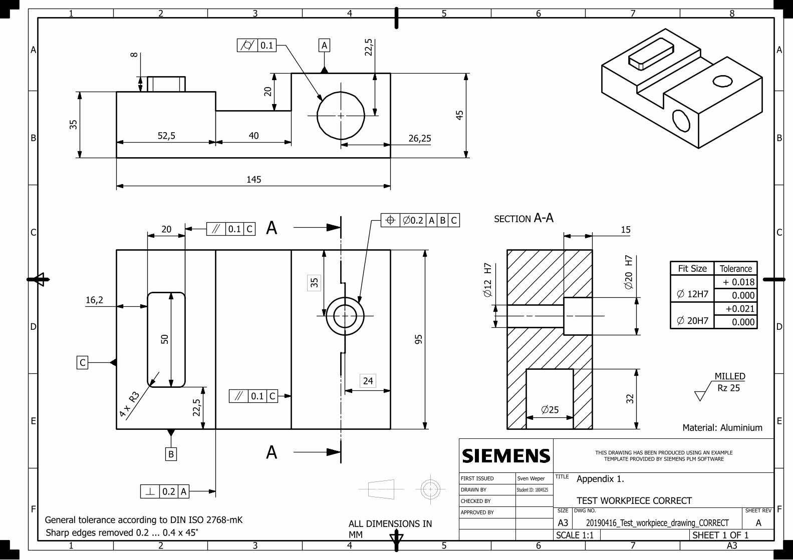
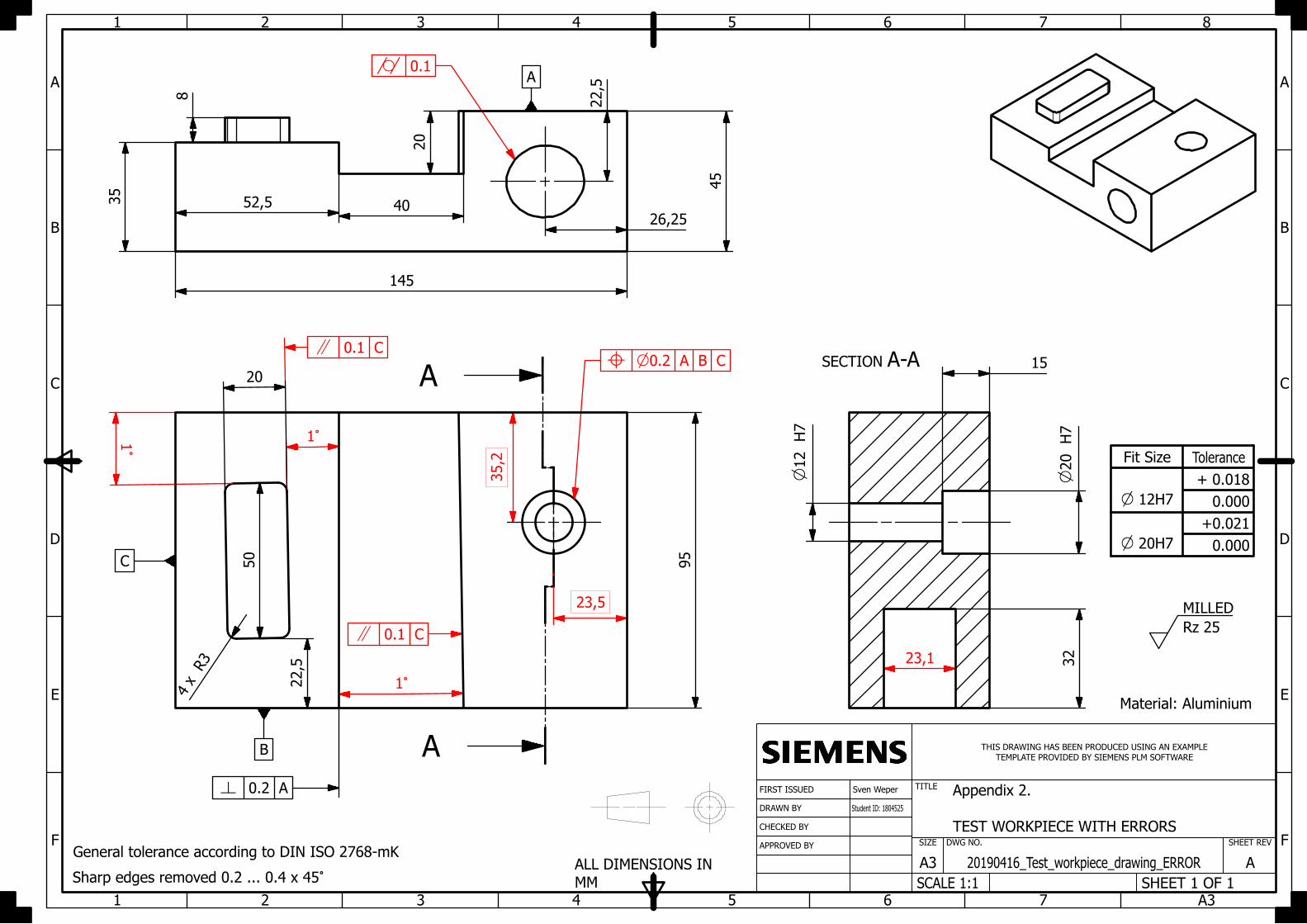
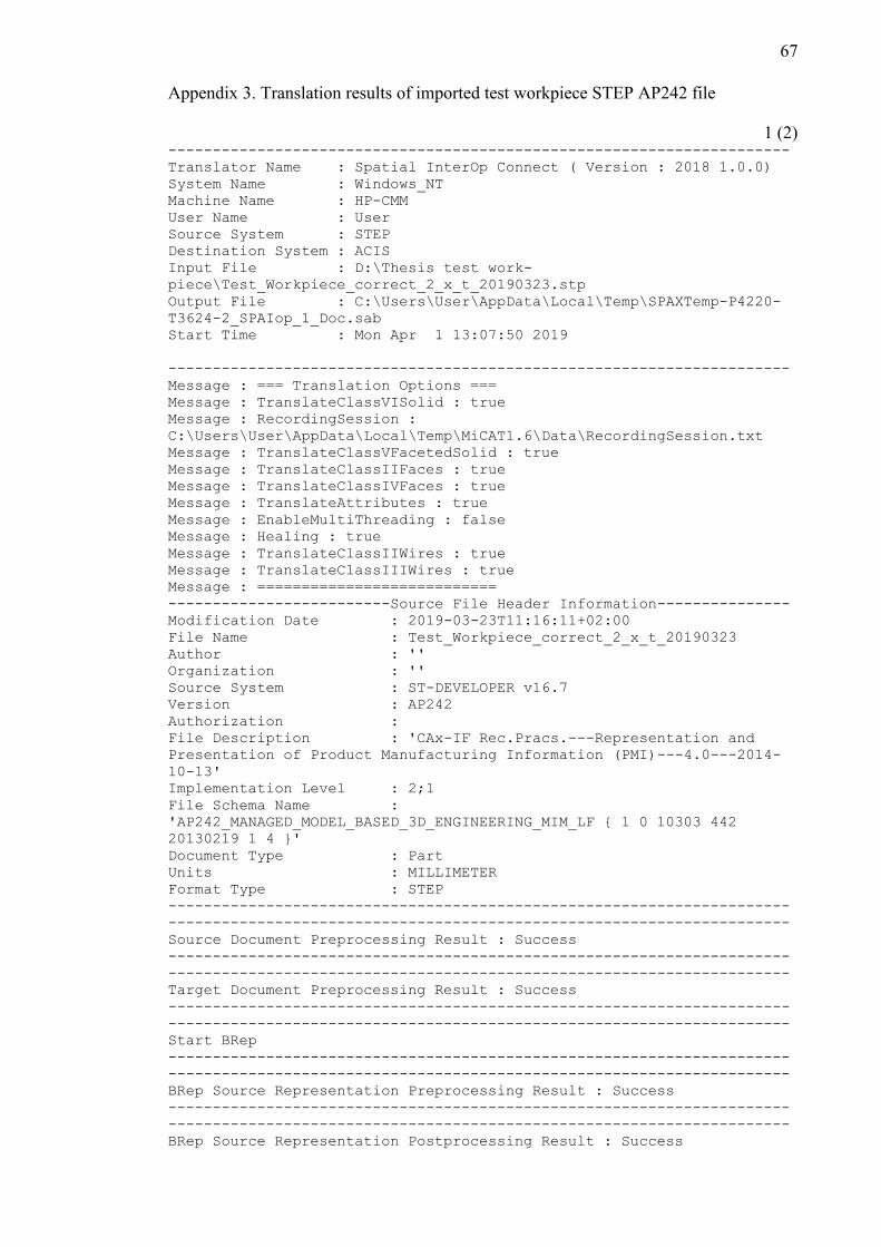
67
Appendix 3. Translation results of imported test workpiece STEP AP242 file
1 (2) ----------------------------------------------------------------------
Translator Name : Spatial InterOp Connect ( Version : 2018 1.0.0)
System Name : Windows_NT
Machine Name : HP-CMM
User Name : User
Source System : STEP
Destination System : ACIS
Input File : D:\Thesis test work-
piece\Test_Workpiece_correct_2_x_t_20190323.stp
Output File : C:\Users\User\AppData\Local\Temp\SPAXTemp-P4220-
T3624-2_SPAIop_1_Doc.sab
Start Time : Mon Apr 1 13:07:50 2019
----------------------------------------------------------------------
Message : === Translation Options ===
Message : TranslateClassVISolid : true
Message : RecordingSession :
C:\Users\User\AppData\Local\Temp\MiCAT1.6\Data\RecordingSession.txt
Message : TranslateClassVFacetedSolid : true
Message : TranslateClassIIFaces : true
Message : TranslateClassIVFaces : true
Message : TranslateAttributes : true
Message : EnableMultiThreading : false
Message : Healing : true
Message : TranslateClassIIWires : true
Message : TranslateClassIIIWires : true
Message : ===========================
-------------------------Source File Header Information---------------
Modification Date : 2019-03-23T11:16:11+02:00
File Name : Test_Workpiece_correct_2_x_t_20190323
Author : ''
Organization : ''
Source System : ST-DEVELOPER v16.7
Version : AP242
Authorization :
File Description : 'CAx-IF Rec.Pracs.---Representation and
Presentation of Product Manufacturing Information (PMI)---4.0---2014-
10-13'
Implementation Level : 2;1
File Schema Name :
'AP242_MANAGED_MODEL_BASED_3D_ENGINEERING_MIM_LF { 1 0 10303 442
20130219 1 4 }'
Document Type : Part
Units : MILLIMETER
Format Type : STEP
----------------------------------------------------------------------
----------------------------------------------------------------------
Source Document Preprocessing Result : Success
----------------------------------------------------------------------
----------------------------------------------------------------------
Target Document Preprocessing Result : Success
----------------------------------------------------------------------
----------------------------------------------------------------------
Start BRep
----------------------------------------------------------------------
----------------------------------------------------------------------
BRep Source Representation Preprocessing Result : Success
----------------------------------------------------------------------
----------------------------------------------------------------------
BRep Source Representation Postprocessing Result : Success
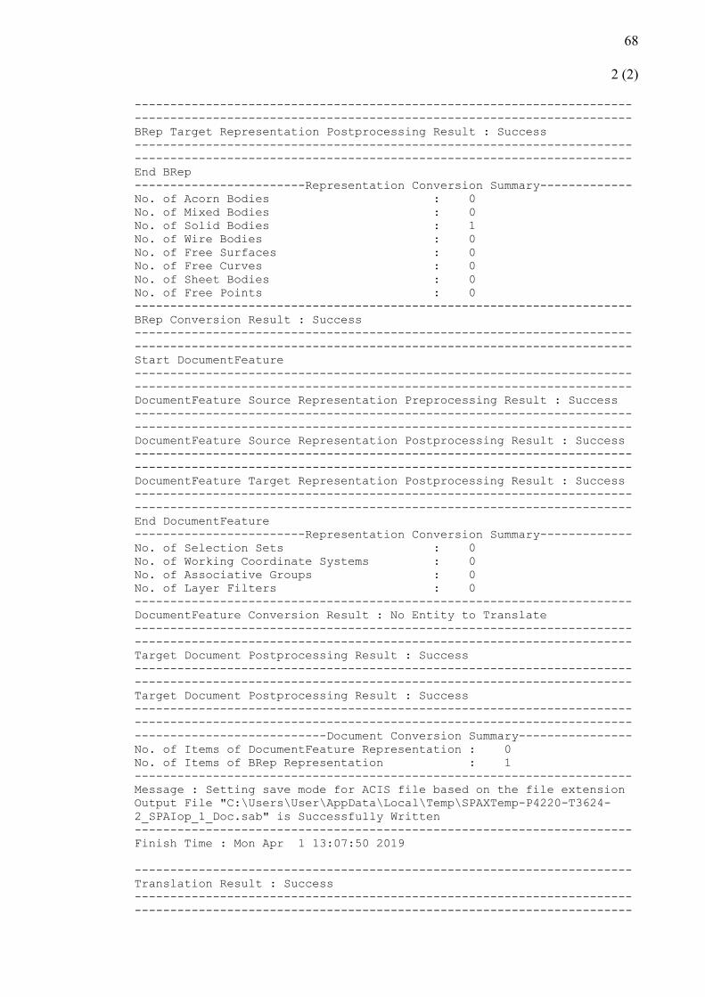
68
2 (2)
----------------------------------------------------------------------
----------------------------------------------------------------------
BRep Target Representation Postprocessing Result : Success
----------------------------------------------------------------------
----------------------------------------------------------------------
End BRep
------------------------Representation Conversion Summary-------------
No. of Acorn Bodies : 0
No. of Mixed Bodies : 0
No. of Solid Bodies : 1
No. of Wire Bodies : 0
No. of Free Surfaces : 0
No. of Free Curves : 0
No. of Sheet Bodies : 0
No. of Free Points : 0
----------------------------------------------------------------------
BRep Conversion Result : Success
----------------------------------------------------------------------
----------------------------------------------------------------------
Start DocumentFeature
----------------------------------------------------------------------
----------------------------------------------------------------------
DocumentFeature Source Representation Preprocessing Result : Success
----------------------------------------------------------------------
----------------------------------------------------------------------
DocumentFeature Source Representation Postprocessing Result : Success
----------------------------------------------------------------------
----------------------------------------------------------------------
DocumentFeature Target Representation Postprocessing Result : Success
----------------------------------------------------------------------
----------------------------------------------------------------------
End DocumentFeature
------------------------Representation Conversion Summary-------------
No. of Selection Sets : 0
No. of Working Coordinate Systems : 0
No. of Associative Groups : 0
No. of Layer Filters : 0
----------------------------------------------------------------------
DocumentFeature Conversion Result : No Entity to Translate
----------------------------------------------------------------------
----------------------------------------------------------------------
Target Document Postprocessing Result : Success
----------------------------------------------------------------------
----------------------------------------------------------------------
Target Document Postprocessing Result : Success
----------------------------------------------------------------------
----------------------------------------------------------------------
---------------------------Document Conversion Summary----------------
No. of Items of DocumentFeature Representation : 0
No. of Items of BRep Representation : 1
----------------------------------------------------------------------
Message : Setting save mode for ACIS file based on the file extension
Output File "C:\Users\User\AppData\Local\Temp\SPAXTemp-P4220-T3624-
2_SPAIop_1_Doc.sab" is Successfully Written
----------------------------------------------------------------------
Finish Time : Mon Apr 1 13:07:50 2019
----------------------------------------------------------------------
Translation Result : Success
----------------------------------------------------------------------
----------------------------------------------------------------------
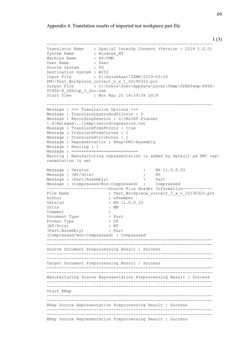
69
Appendix 4. Translation results of imported test workpiece part file
1 (3) -------------------------------------------------------------------
Translator Name : Spatial InterOp Connect (Version : 2018 1.0.0)
System Name : Windows_NT
Machine Name : HP-CMM
User Name : User
Source System : UG
Destination System : ACIS
Input File : Z:\Asiakkaat\TAMK\2019-03-25
PMI\Test_Workpiece_correct_2_x_t_20190323.prt
Output File : C:\Users\User\AppData\Local\Temp\SPAXTemp-P860-
T5900-8_SPAIop_3_Doc.sab
Start Time : Mon Mar 25 14:39:34 2019
-------------------------------------------------------------------
Message : === Translation Options ===
Message : TranslateLayersAndFilters : 0
Message : RecordingSession : C:\MiCAT Planner
1.6\Release\..\temp\recordingsession.txt
Message : TranslateFreePoints : true
Message : TranslateFreeCurves : 1
Message : TranslateAttributes : 1
Message : Representation : BRep+PMI+Assembly
Message : Healing : 1
Message : ===========================
Warning : Manufacturing representation is added by default as PMI rep-
resentation is set
Message : Version : NX 11.0.0.33
Message : (NT/Unix) : NT
Message : (Part/Assembly) : Part
Message : (Compressed/Non-Compressed) : Compressed
-------------------------Source File Header Information------------
File Name : Test_Workpiece_correct_2_x_t_20190323.prt
Author : e8sweper
Version : NX 11.0.0.33
Units : MM
Comment :
Document Type : Part
Format Type : UG
(NT/Unix) : NT
(Part/Assembly) : Part
(Compressed/Non-Compressed) : Compressed
-------------------------------------------------------------------
-------------------------------------------------------------------
Source Document Preprocessing Result : Success
-------------------------------------------------------------------
-------------------------------------------------------------------
Target Document Preprocessing Result : Success
-------------------------------------------------------------------
-------------------------------------------------------------------
Manufacturing Source Representation Preprocessing Result : Success
-------------------------------------------------------------------
-------------------------------------------------------------------
Start BRep
-------------------------------------------------------------------
-------------------------------------------------------------------
BRep Source Representation Preprocessing Result : Success
-------------------------------------------------------------------
-------------------------------------------------------------------
BRep Source Representation Preprocessing Result : Success
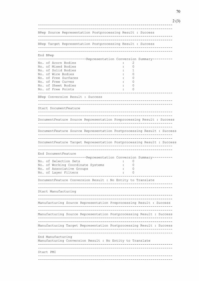
70
2 (3) -------------------------------------------------------------------
-------------------------------------------------------------------
BRep Source Representation Postprocessing Result : Success
-------------------------------------------------------------------
-------------------------------------------------------------------
BRep Target Representation Postprocessing Result : Success
-------------------------------------------------------------------
-------------------------------------------------------------------
End BRep
------------------------Representation Conversion Summary----------
No. of Acorn Bodies : 2
No. of Mixed Bodies : 0
No. of Solid Bodies : 1
No. of Wire Bodies : 0
No. of Free Surfaces : 0
No. of Free Curves : 0
No. of Sheet Bodies : 0
No. of Free Points : 0
-------------------------------------------------------------------
BRep Conversion Result : Success
-------------------------------------------------------------------
-------------------------------------------------------------------
Start DocumentFeature
-------------------------------------------------------------------
-------------------------------------------------------------------
DocumentFeature Source Representation Preprocessing Result : Success
-------------------------------------------------------------------
-------------------------------------------------------------------
DocumentFeature Source Representation Postprocessing Result : Success
-------------------------------------------------------------------
-------------------------------------------------------------------
DocumentFeature Target Representation Postprocessing Result : Success
-------------------------------------------------------------------
-------------------------------------------------------------------
End DocumentFeature
------------------------Representation Conversion Summary----------
No. of Selection Sets : 0
No. of Working Coordinate Systems : 0
No. of Associative Groups : 0
No. of Layer Filters : 0
-------------------------------------------------------------------
DocumentFeature Conversion Result : No Entity to Translate
-------------------------------------------------------------------
-------------------------------------------------------------------
Start Manufacturing
-------------------------------------------------------------------
-------------------------------------------------------------------
Manufacturing Source Representation Preprocessing Result : Success
-------------------------------------------------------------------
-------------------------------------------------------------------
Manufacturing Source Representation Postprocessing Result : Success
-------------------------------------------------------------------
-------------------------------------------------------------------
Manufacturing Target Representation Postprocessing Result : Success
-------------------------------------------------------------------
-------------------------------------------------------------------
End Manufacturing
Manufacturing Conversion Result : No Entity to Translate
-------------------------------------------------------------------
-------------------------------------------------------------------
Start PMI
-------------------------------------------------------------------
-------------------------------------------------------------------
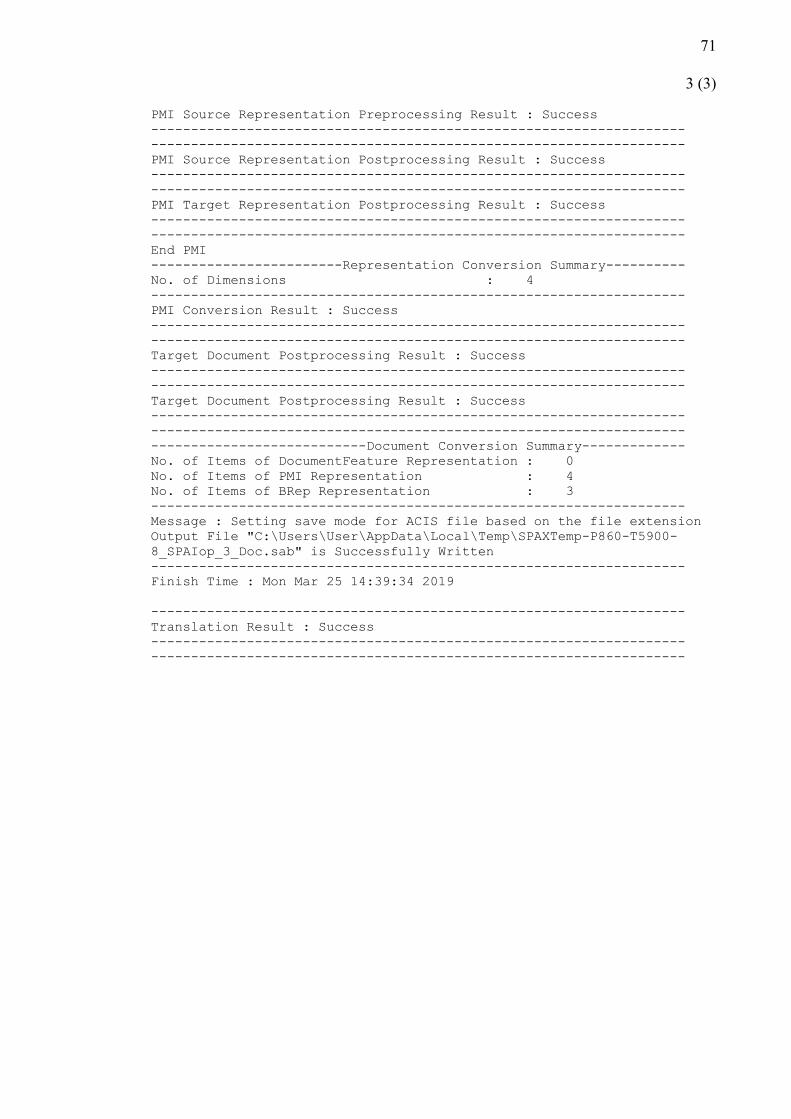
71
3 (3)
PMI Source Representation Preprocessing Result : Success
-------------------------------------------------------------------
-------------------------------------------------------------------
PMI Source Representation Postprocessing Result : Success
-------------------------------------------------------------------
-------------------------------------------------------------------
PMI Target Representation Postprocessing Result : Success
-------------------------------------------------------------------
-------------------------------------------------------------------
End PMI
------------------------Representation Conversion Summary----------
No. of Dimensions : 4
-------------------------------------------------------------------
PMI Conversion Result : Success
-------------------------------------------------------------------
-------------------------------------------------------------------
Target Document Postprocessing Result : Success
-------------------------------------------------------------------
-------------------------------------------------------------------
Target Document Postprocessing Result : Success
-------------------------------------------------------------------
-------------------------------------------------------------------
---------------------------Document Conversion Summary-------------
No. of Items of DocumentFeature Representation : 0
No. of Items of PMI Representation : 4
No. of Items of BRep Representation : 3
-------------------------------------------------------------------
Message : Setting save mode for ACIS file based on the file extension
Output File "C:\Users\User\AppData\Local\Temp\SPAXTemp-P860-T5900-
8_SPAIop_3_Doc.sab" is Successfully Written
-------------------------------------------------------------------
Finish Time : Mon Mar 25 14:39:34 2019
-------------------------------------------------------------------
Translation Result : Success
-------------------------------------------------------------------
-------------------------------------------------------------------
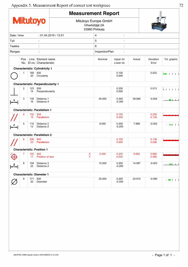
- Page 1 of 1 -
Date / time : 01.04.2019 / 12:51
Työ :
Taakka :
Rengas :
4 :
5 :
6 :
InspectionPlan :
Mitutoyo Europe GmbH
Viherkiitäjä 2A
33960 Pirkkala
Measurement Report
GEOPAK CMM repeat mode in MCOSMOS-3 v4.3.B1
Pos. Line Element name Nominal Upper tol. Actual Deviation Tol. graphicNo. El.no. Characteristic Lower tol. Error
Characteristic: Cylindricity 11 169
20830Circularity
0.1000.000
0.022
Characteristic: Perpendicularity 12 123
14839Perpendicularity
0.2000.000
0.013
3 13516
Distance 1Distance X
40.000 0.300-0.300
39.946 -0.054
Characteristic: Parallelism 14 132
15834Parallelism
0.1000.000
0.2350.135
5 11513
Distance 2Distance Z
8.000 0.200-0.200
7.998 -0.002
Characteristic: Parallelism 26 206
23843Parallelism
0.1000.000
0.1360.036
Characteristic: Position 17 150
17842Position of axis
XY
0.000 0.2000.000
0.682 0.6820.482
8 19422
Distance 3Distance Z
15.000 0.200-0.200
14.997 -0.003
Characteristic: Diameter 19 171
20830Diameter
25.000 0.200-0.200
24.910 -0.090
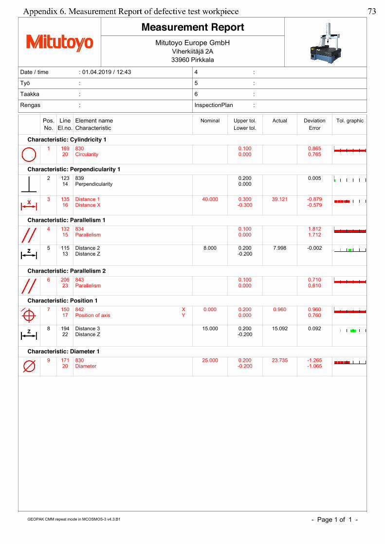
- Page 1 of 1 -
Date / time : 01.04.2019 / 12:43
Työ :
Taakka :
Rengas :
4 :
5 :
6 :
InspectionPlan :
Mitutoyo Europe GmbH
Viherkiitäjä 2A
33960 Pirkkala
Measurement Report
GEOPAK CMM repeat mode in MCOSMOS-3 v4.3.B1
Pos. Line Element name Nominal Upper tol. Actual Deviation Tol. graphicNo. El.no. Characteristic Lower tol. Error
Characteristic: Cylindricity 11 169
20830Circularity
0.1000.000
0.8650.765
Characteristic: Perpendicularity 12 123
14839Perpendicularity
0.2000.000
0.005
3 13516
Distance 1Distance X
40.000 0.300-0.300
39.121 -0.879-0.579
Characteristic: Parallelism 14 132
15834Parallelism
0.1000.000
1.8121.712
5 11513
Distance 2Distance Z
8.000 0.200-0.200
7.998 -0.002
Characteristic: Parallelism 26 206
23843Parallelism
0.1000.000
0.7100.610
Characteristic: Position 17 150
17842Position of axis
XY
0.000 0.2000.000
0.960 0.9600.760
8 19422
Distance 3Distance Z
15.000 0.200-0.200
15.092 0.092
Characteristic: Diameter 19 171
20830Diameter
25.000 0.200-0.200
23.735 -1.265-1.065


![SAFE: Formal Specification and Implementation of a Scalable … · 2012-10-02 · tion of SAFE (Scalable Analysis Framework for ECMAScript) [30], developed for the JavaScript research](https://img.pdfslide.org/doc/110x75/5ec9d0b8ea65d0120411f66b/safe-formal-speciication-and-implementation-of-a-scalable-2012-10-02-tion-of.jpg)


![Compiler Construction - Lecture : [1ex] Summer Semester ... · Lecture 3: Lexical Analysis II (Extended Matching Problem) Implementation of FLM Analysis (4) The Backtracking DFA I](https://img.pdfslide.org/doc/110x75/60040cae2cef59565b19bc4a/compiler-construction-lecture-1ex-summer-semester-lecture-3-lexical-analysis.jpg)


![GTZ - EPA Implementation Stakeholder Analysis - The Cariforum Context [March 2009]](https://img.pdfslide.org/doc/110x75/577d2f2b1a28ab4e1eb0fcab/gtz-epa-implementation-stakeholder-analysis-the-cariforum-context-march.jpg)