Embed Size (px)
Citation preview
1 4029001-1108
www.ikarus.net 4021001
Deutsch: Montageanleitung 1/10 Hovercraft „Craftair“
English: Assembly Instructions 1/10 scale Hovercraft “Craftair”
2
Lieferumfang
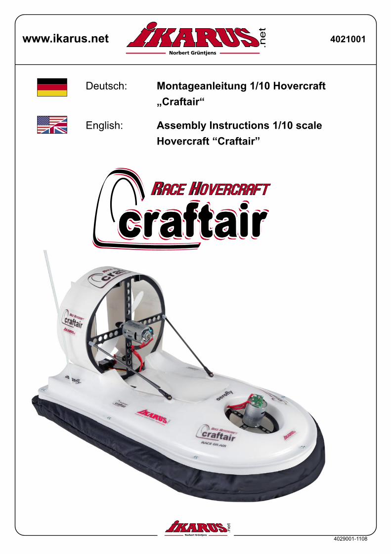
Ober- und UnterschaleSchürzenABS Platten
GFK FrästeileCFK Rundmaterial
BalsaklötzeAntennenrohrLuftschraubenHaken- und ÖsenbandKleinteile und Schrauben
Zum Aufbau benötigen Sie außerdem:- Skalpell- Schere- Sekundenkleber, 2-Komponenten Kleber
- Inbusschlüssel 1,5 mm- Spitzzange- Doppelseitiges Klebeband- Karosseriebohrer, Spiralbohrer Ø3 u. Ø4 mm
3
Ober- und Unterschale
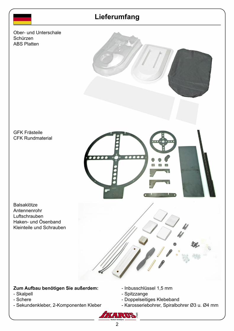
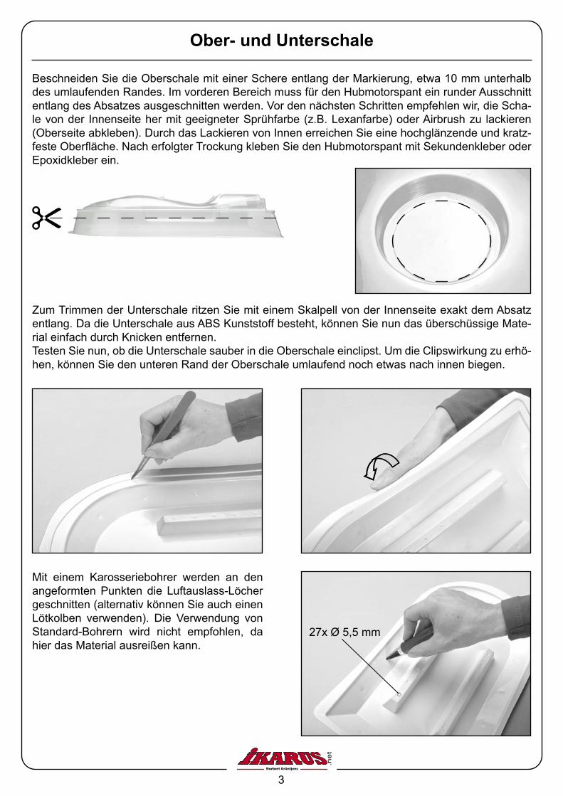
Beschneiden Sie die Oberschale mit einer Schere entlang der Markierung, etwa 10 mm unterhalb des umlaufenden Randes. Im vorderen Bereich muss für den Hubmotorspant ein runder Ausschnitt entlang des Absatzes ausgeschnitten werden. Vor den nächsten Schritten empfehlen wir, die Scha-le von der Innenseite her mit geeigneter Sprühfarbe (z.B. Lexanfarbe) oder Airbrush zu lackieren (Oberseite abkleben). Durch das Lackieren von Innen erreichen Sie eine hochglänzende und kratz-feste Oberfläche. Nach erfolgter Trockung kleben Sie den Hubmotorspant mit Sekundenkleber oder Epoxidkleber ein.
Zum Trimmen der Unterschale ritzen Sie mit einem Skalpell von der Innenseite exakt dem Absatz entlang. Da die Unterschale aus ABS Kunststoff besteht, können Sie nun das überschüssige Mate-rial einfach durch Knicken entfernen. Testen Sie nun, ob die Unterschale sauber in die Oberschale einclipst. Um die Clipswirkung zu erhö-hen, können Sie den unteren Rand der Oberschale umlaufend noch etwas nach innen biegen.
Mit einem Karosseriebohrer werden an den angeformten Punkten die Luftauslass-Löcher geschnitten (alternativ können Sie auch einen Lötkolben verwenden). Die Verwendung von Standard-Bohrern wird nicht empfohlen, da hier das Material ausreißen kann.
27x Ø 5,5 mm
4
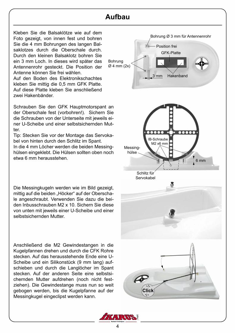
Aufbau
Kleben Sie die Balsaklötze wie auf dem Foto gezeigt, von innen fest und bohren Sie die 4 mm Bohrungen des langen Bal-saklotzes durch die Oberschale durch. Durch den kleinen Balsaklotz bohren Sie ein 3 mm Loch. In dieses wird später das Antennenrohr gesteckt. Die Position der Antenne können Sie frei wählen.Auf den Boden des Elektronikschachtes kleben Sie mittig die 0,5 mm GFK Platte. Auf diese Platte kleben Sie anschließend zwei Hakenbänder.
3 mm
Position frei
Bohrung Ø 3 mm für Antennenrohr
Bohrung Ø 4 mm (2x)
Die Messingkugeln werden wie im Bild gezeigt, mittig auf die beiden „Höcker“ auf der Oberscha-le angeschraubt. Verwenden Sie dazu die bei-den Inbusschrauben M2 x 10. Sichern Sie diese von unten mit jeweils einer U-Scheibe und einer selbstsichernden Mutter.
Schrauben Sie den GFK Hauptmotorspant an der Oberschale fest (vorbohren!). Sichern Sie die Schrauben von der Unterseite mit jeweils ei-ner U-Scheibe und einer selbstsichernden Mut-ter. Tip: Stecken Sie vor der Montage das Servoka-bel von hinten durch den Schlitz im Spant.In die 4 mm Löcher werden die beiden Messing-hülsen eingeklebt. Die Hülsen sollten oben noch etwa 6 mm herausstehen.
Anschließend die M2 Gewindestangen in die Kugelpfannen drehen und durch die CFK Rohre stecken. Auf das herausstehende Ende eine U-Scheibe und ein Silikonstück (9 mm lang) auf-schieben und durch die Langlöcher im Spant stecken. Auf der anderen Seite eine selbstsi-chernden Mutter aufdrehen (noch nicht fest-ziehen). Die Gewindestange muss nun so weit gebogen werden, bis die Kugelpfanne auf der Messingkugel eingeclipst werden kann.
kcilC
6 mm
IB-Schraube M2 x6 mm
Messing-hülse
Schlitz für Servokabel
GFK-Platte
Hakenband
5
Parallel
ca. 35°
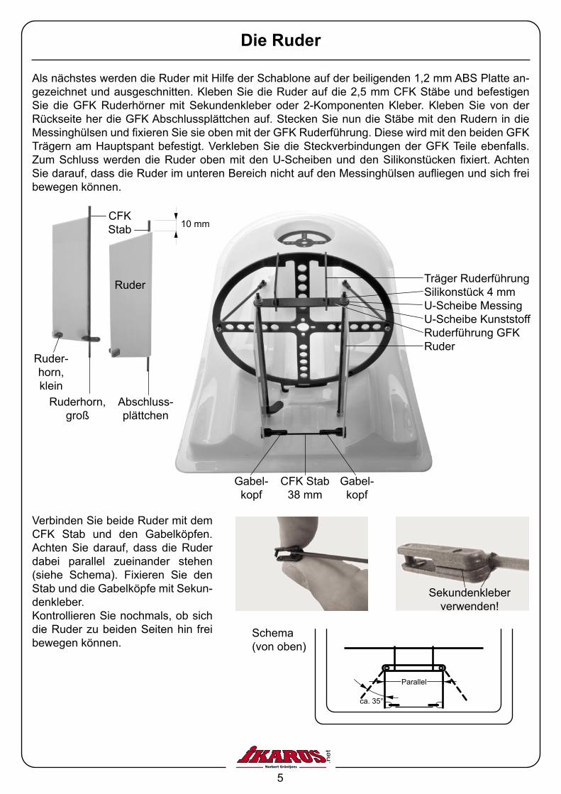
Die Ruder
Verbinden Sie beide Ruder mit dem CFK Stab und den Gabelköpfen. Achten Sie darauf, dass die Ruder dabei parallel zueinander stehen (siehe Schema). Fixieren Sie den Stab und die Gabelköpfe mit Sekun-denkleber.Kontrollieren Sie nochmals, ob sich die Ruder zu beiden Seiten hin frei bewegen können.
Träger RuderführungSilikonstück 4 mmU-Scheibe MessingU-Scheibe KunststoffRuderführung GFKRuder
Gabel-kopf
CFK Stab 38 mm
Gabel-kopf
Schema(von oben)
10 mm
Abschluss-plättchen
Ruder-horn, klein
Ruderhorn, groß
Ruder
CFK Stab
Sekundenkleber verwenden!
Als nächstes werden die Ruder mit Hilfe der Schablone auf der beiligenden 1,2 mm ABS Platte an-gezeichnet und ausgeschnitten. Kleben Sie die Ruder auf die 2,5 mm CFK Stäbe und befestigen Sie die GFK Ruderhörner mit Sekundenkleber oder 2-Komponenten Kleber. Kleben Sie von der Rückseite her die GFK Abschlussplättchen auf. Stecken Sie nun die Stäbe mit den Rudern in die Messinghülsen und fixieren Sie sie oben mit der GFK Ruderführung. Diese wird mit den beiden GFK Trägern am Hauptspant befestigt. Verkleben Sie die Steckverbindungen der GFK Teile ebenfalls. Zum Schluss werden die Ruder oben mit den U-Scheiben und den Silikonstücken fixiert. Achten Sie darauf, dass die Ruder im unteren Bereich nicht auf den Messinghülsen aufliegen und sich frei bewegen können.
6
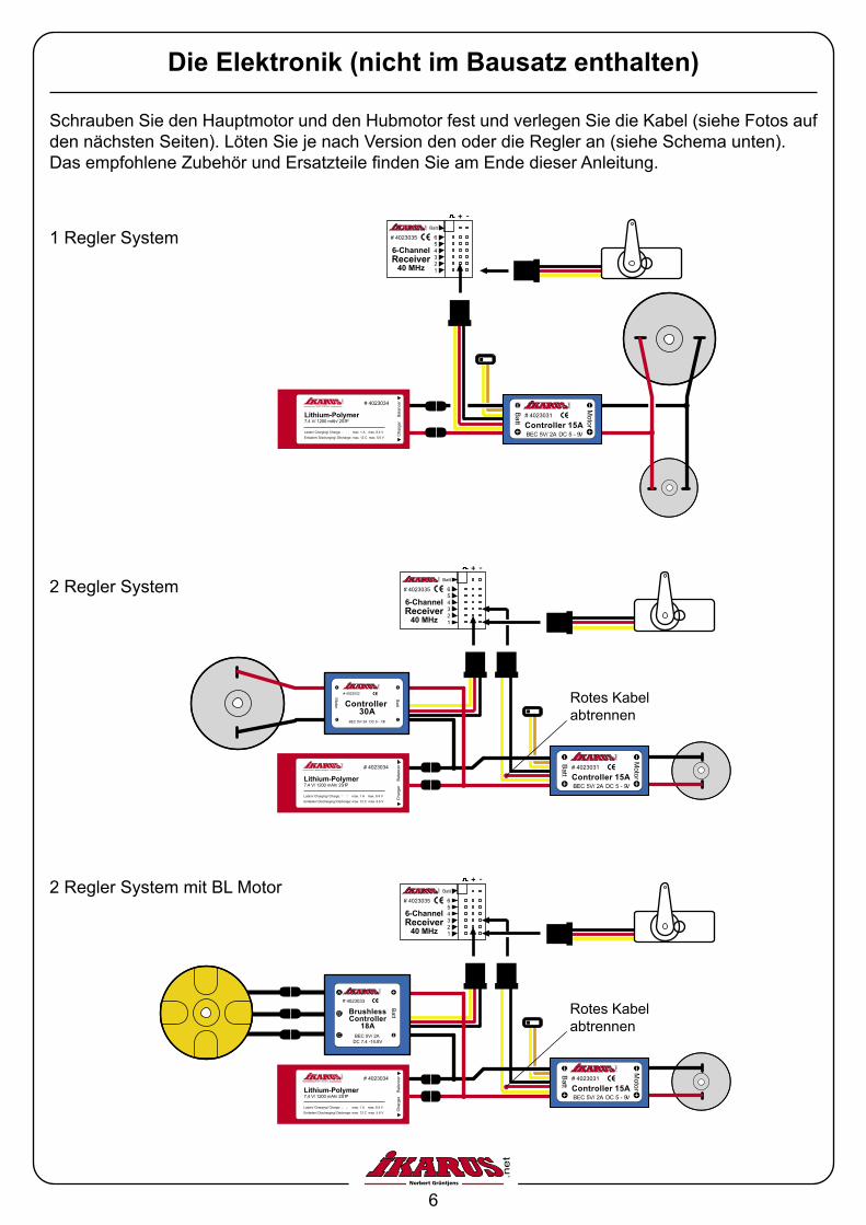
Schrauben Sie den Hauptmotor und den Hubmotor fest und verlegen Sie die Kabel (siehe Fotos auf den nächsten Seiten). Löten Sie je nach Version den oder die Regler an (siehe Schema unten). Das empfohlene Zubehör und Ersatzteile finden Sie am Ende dieser Anleitung.
Die Elektronik (nicht im Bausatz enthalten)
# 4023031
Controller 15A
Batt
BEC 5V/ 2A DC 5 - 9V
Motor
# 4023034
Lithium-Polymer7,4 V/ 1200 mAh/ 2S1P
Laden/ Charging/ Charge: � � max. 1 A max. 8.4 V
Entladen/ Discharging/ Décharge: max. 12 C max. 5.6 V
Bal
ance
rC
harg
er
# 4023035
Batt
654321
6-ChannelReceiver
40 MHz
1 Regler System
2 Regler System
2 Regler System mit BL Motor
# 4023032
Controller 30A
Batt
BEC 5V/ 2A DC 9 - 13V
Motor
# 4023034
Lithium-Polymer7,4 V/ 1200 mAh/ 2S1P
Laden/ Charging/ Charge: � � max. 1 A max. 8.4 V
Entladen/ Discharging/ Décharge: max. 12 C max. 5.6 V
Bal
ance
rC
harg
er
# 4023035
Batt
654321
6-ChannelReceiver
40 MHz
# 4023031
Controller 15A
Batt
BEC 5V/ 2A DC 5 - 9V
Motor
Rotes Kabel abtrennen
# 4023034
Lithium-Polymer7,4 V/ 1200 mAh/ 2S1P
Laden/ Charging/ Charge: � � max. 1 A max. 8.4 V
Entladen/ Discharging/ Décharge: max. 12 C max. 5.6 V
Bal
ance
rC
harg
er
# 4023035
Batt
654321
6-ChannelReceiver
40 MHz
# 4023031
Controller 15A
Batt
BEC 5V/ 2A DC 5 - 9V
Motor
# 4023033
BrushlessController
18A
Batt
BEC 5V/ 2A DC 7.4 -14.8V
Rotes Kabel abtrennen
7
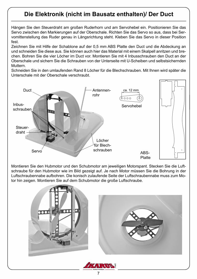
Hängen Sie den Steuerdraht am großen Ruderhorn und am Servohebel ein. Positionieren Sie das Servo zwischen den Markierungen auf der Oberschale. Richten Sie das Servo so aus, dass bei Ser-vomittenstellung das Ruder genau in Längsrichtung steht. Kleben Sie das Servo in dieser Position fest.Zeichnen Sie mit Hilfe der Schablone auf der 0,5 mm ABS Platte den Duct und die Abdeckung an und schneiden Sie diese aus. Sie können auch hier das Material mit einem Skalpell anritzen und bre-chen. Bohren Sie die vier Löcher im Duct vor. Montieren Sie mit 4 Inbusschrauben den Duct an der Oberschale und sichern Sie die Schrauben von der Unterseite mit U-Scheiben und selbstsichernden Muttern.Schneiden Sie in den umlaufenden Rand 8 Löcher für die Blechschrauben. Mit Ihnen wird später die Unterschale mit der Oberschale verschraubt.
Servo
Antennen-rohr
Steuer-draht
Inbus-schrauben
Duct
Löcher für Blech-schrauben
Die Elektronik (nicht im Bausatz enthalten)/ Der Duct
ABS-Platte
Montieren Sie den Hubmotor und den Schubmotor am jeweiligen Motorspant. Stecken Sie die Luft-schraube für den Hubmotor wie im Bild gezeigt auf. Je nach Motor müssen Sie die Bohrung in der Luftschraubennabe aufbohren. Die konisch zulaufende Seite der Luftschraubennabe muss zum Mo-tor hin zeigen. Montieren Sie auf dem Schubmotor die große Luftschraube.
Servohebel
ca. 12 mm
8
EmpfängerAkkuReglerBlechschraube
Abb. 3
Durchgangslöcher für Kabel
Schlitz für ABSAbdeckung
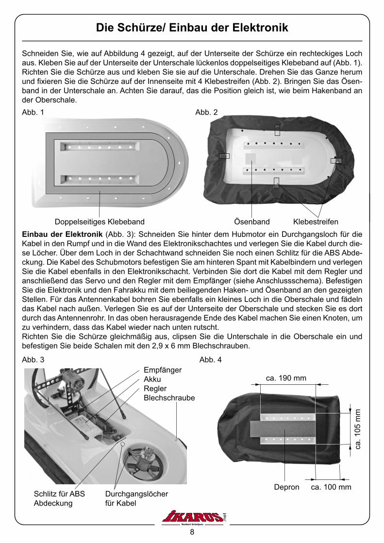
Die Schürze/ Einbau der Elektronik
Schneiden Sie, wie auf Abbildung 4 gezeigt, auf der Unterseite der Schürze ein rechteckiges Loch aus. Kleben Sie auf der Unterseite der Unterschale lückenlos doppelseitiges Klebeband auf (Abb. 1). Richten Sie die Schürze aus und kleben Sie sie auf die Unterschale. Drehen Sie das Ganze herum und fixieren Sie die Schürze auf der Innenseite mit 4 Klebestreifen (Abb. 2). Bringen Sie das Ösen-band in der Unterschale an. Achten Sie darauf, das die Position gleich ist, wie beim Hakenband an der Oberschale.
Einbau der Elektronik (Abb. 3): Schneiden Sie hinter dem Hubmotor ein Durchgangsloch für die Kabel in den Rumpf und in die Wand des Elektronikschachtes und verlegen Sie die Kabel durch die-se Löcher. Über dem Loch in der Schachtwand schneiden Sie noch einen Schlitz für die ABS Abde-ckung. Die Kabel des Schubmotors befestigen Sie am hinteren Spant mit Kabelbindern und verlegen Sie die Kabel ebenfalls in den Elektronikschacht. Verbinden Sie dort die Kabel mit dem Regler und anschließend das Servo und den Regler mit dem Empfänger (siehe Anschlussschema). Befestigen Sie die Elektronik und den Fahrakku mit dem beiliegenden Haken- und Ösenband an den gezeigten Stellen. Für das Antennenkabel bohren Sie ebenfalls ein kleines Loch in die Oberschale und fädeln das Kabel nach außen. Verlegen Sie es auf der Unterseite der Oberschale und stecken Sie es dort durch das Antennenrohr. In das oben herausragende Ende des Kabel machen Sie einen Knoten, um zu verhindern, dass das Kabel wieder nach unten rutscht.Richten Sie die Schürze gleichmäßig aus, clipsen Sie die Unterschale in die Oberschale ein und befestigen Sie beide Schalen mit den 2,9 x 6 mm Blechschrauben.
Doppelseitiges Klebeband
Abb. 1
Ösenband Klebestreifen
Abb. 2
Depron
Abb. 4
ca. 190 mm
ca. 100 mm
ca. 1
05 m
m
9
Tipps zum Fahren
Das Fahren eines Hovercrafts ist nicht mit dem Fahren eines RC-Autos zu vergleichen. Da im Grun-de kein Bodenkontakt besteht und das Modell dicht über dem Boden schwebt, ist das gezielte Ab-bremsen und Steuern zu üben. Wir empfehlen, dass Sie sich ein freies Gelände ohne Hindernisse für Ihre ersten Fahrversuche aussuchen. Stellen Sie fest, dass das Hovercraft beim Beschleunigen „die Nase“ nach unten drückt und dadurch abgebremst wird, korrigieren Sie den Sturz. Drehen Sie die Muttern am Gestänge zwischen Spant und Oberschale weiter hinein, so dass sich der Spant etwas nach vorne neigt.Dreht das Hovercraft trotz gerade eingestellter Ruder zur Seite, muss der Seitenzug eingestellt wer-den. Stellen Sie auch dies – wie den Sturz – über Herein- bzw. Herausdrehen der Muttern am Ge-stänge ein, um auf diese Weise den Spant seitwärts zu verdrehen. Wollen Sie mit Ihrem Hovercraft zügig von hoher Geschwindigkeit abbremsen, muss dazu mit etwas Schub ein Vollausschlag mit dem Ruder gegeben werden. Leiten Sie somit eine 180°-Drehung ein. Die Bewegungsrichtung bleibt vorerst nahezu unverändert. Fährt das Modell mit dem Heck voraus, geben Sie „Vollgas“, um das Hovercraft möglichst schnell zum Stehen zu bringen. Üben Sie unbe-dingt auf diese Weise zu Bremsen, wenn Sie das Modell ständig durch „Absetzen“ (ausschalten des Hub-Antriebs) abbremsen, erhöht sich der Verschleiß.
Für dieses IKARUS Produkt übernehmen wir eine Gewährleistung von 24 Monaten. Als Beleg für den Beginn und den Ablauf dieser Gewährleistung dient die Kaufquittung. Eventuelle Reparaturen verlängern den Ge-währleistungszeitraum nicht. Wenn im Garantiezeitraum Funktionsmängel, Fabrikations- oder Materialfehler auftreten, werden diese von uns behoben. Weitere Ansprüche, z. B. bei Folgeschäden, sind komplett ausge-schlossen. Reparatureinsendungen bitte an die unten angegebene Adresse. Bei Einsendung eines Gerätes, das sich nach der Eingangsprüfung als funktionsfähig herausstellt, erheben wir eine Bearbeitungsgebühr von 20,- €. Der Transport muss frei erfolgen, der Rücktransport erfolgt ebenfalls frei. Unfreie Sendungen können nicht angenommen werden. Für Schäden, die beim Transport Ihrer Zusendung erfolgen, übernehmen wir keine Haftung. Auch der Verlust Ihrer Sendung ist von der Haftung durch uns ausgeschlossen.Bei Rückfragen und technischen Problemen nutzen Sie unsere Service-Hotline unter der Nummer 0900 1 – 79 50 20 (0,99 €/ Min. Erreichbar von Montag bis Donnerstag in der Zeit von 10 Uhr bis 12 Uhr und von 13 Uhr bis 16 Uhr, freitags von 14 Uhr bis 16 Uhr).
Gewährleistungsbestimmungen
www.ikarus.net
Ikarus ModellsportIm Webertal 22D-78713 Schramberg-Waldmössingen
Bestellhotline: +49 (0) 74 02/ 92 91-900Service: (0,99 €/Min.) 0 900 1/ 79 50 20Fax: +49 (0) 74 02/ 92 91-750International Call Center: +49 (0) 74 02/ 92 [email protected]
10
Zubehör und Ersatzteile
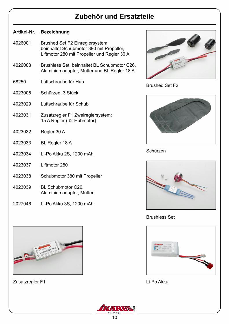
Artikel-Nr. Bezeichnung
4026001 Brushed Set F2 Einreglersystem, beinhaltet Schubmotor 380 mit Propeller, Liftmotor 280 mit Propeller und Regler 30 A
4026003 Brushless Set, beinhaltet BL Schubmotor C26, Aluminiumadapter, Mutter und BL Regler 18 A.
68250 Luftschraube für Hub
4023005 Schürzen, 3 Stück
4023029 Luftschraube für Schub
4023031 Zusatzregler F1 Zweireglersystem: 15 A Regler (für Hubmotor)
4023032 Regler 30 A
4023033 BL Regler 18 A
4023034 Li-Po Akku 2S, 1200 mAh
4023037 Liftmotor 280
4023038 Schubmotor 380 mit Propeller
4023039 BL Schubmotor C26, Aluminiumadapter, Mutter
2027046 Li-Po Akku 3S, 1200 mAh
Brushed Set F2
Schürzen
Brushless Set
Li-Po AkkuZusatzregler F1
11
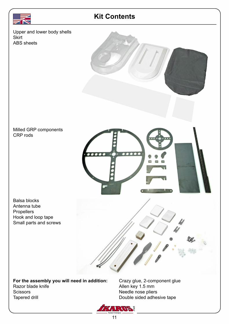
Kit Contents
Upper and lower body shellsSkirtABS sheets
Milled GRP componentsCRP rods
Balsa blocksAntenna tubePropellersHook and loop tapeSmall parts and screws
For the assembly you will need in addition:Razor blade knifeScissorsTapered drill
Crazy glue, 2-component glueAllen key 1.5 mmNeedle nose pliersDouble sided adhesive tape
12
Upper and lower body shells
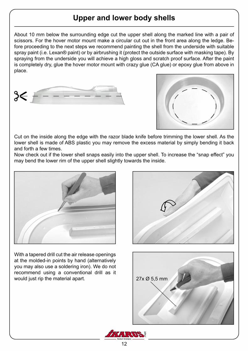
About 10 mm below the surrounding edge cut the upper shell along the marked line with a pair of scissors. For the hover motor mount make a circular cut out in the front area along the ledge. Be-fore proceeding to the next steps we recommend painting the shell from the underside with suitable spray paint (i.e. Lexan® paint) or by airbrushing it (protect the outside surface with masking tape). By spraying from the underside you will achieve a high gloss and scratch proof surface. After the paint is completely dry, glue the hover motor mount with crazy glue (CA glue) or epoxy glue from above in place.
Cut on the inside along the edge with the razor blade knife before trimming the lower shell. As the lower shell is made of ABS plastic you may remove the excess material by simply bending it back and forth a few times. Now check out if the lower shell snaps easily into the upper shell. To increase the “snap effect” you may bend the lower rim of the upper shell slightly towards the inside.
With a tapered drill cut the air release openings at the molded-in points by hand (alternatively you may also use a soldering iron). We do not recommend using a conventional drill as it would just rip the material apart. 27x Ø 5,5 mm
13
Upper shell assembly
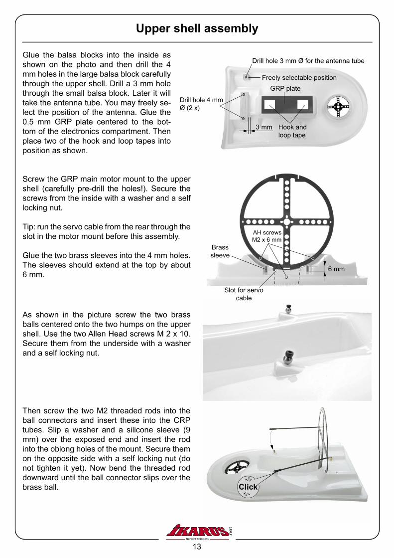
Glue the balsa blocks into the inside as shown on the photo and then drill the 4 mm holes in the large balsa block carefully through the upper shell. Drill a 3 mm hole through the small balsa block. Later it will take the antenna tube. You may freely se-lect the position of the antenna. Glue the 0.5 mm GRP plate centered to the bot-tom of the electronics compartment. Then place two of the hook and loop tapes into position as shown.
3 mm
Freely selectable position
Drill hole 3 mm Ø for the antenna tube
Drill hole 4 mm Ø (2 x)
As shown in the picture screw the two brass balls centered onto the two humps on the upper shell. Use the two Allen Head screws M 2 x 10. Secure them from the underside with a washer and a self locking nut.
Screw the GRP main motor mount to the upper shell (carefully pre-drill the holes!). Secure the screws from the inside with a washer and a self locking nut.
Tip: run the servo cable from the rear through the slot in the motor mount before this assembly.
Glue the two brass sleeves into the 4 mm holes. The sleeves should extend at the top by about 6 mm.
Then screw the two M2 threaded rods into the ball connectors and insert these into the CRP tubes. Slip a washer and a silicone sleeve (9 mm) over the exposed end and insert the rod into the oblong holes of the mount. Secure them on the opposite side with a self locking nut (do not tighten it yet). Now bend the threaded rod downward until the ball connector slips over the brass ball. kcilC
6 mm
AH screws M2 x 6 mm
Brass sleeve
Slot for servo cable
GRP plate
Hook and loop tape
14
Parallel
Approx 35°
The Rudder
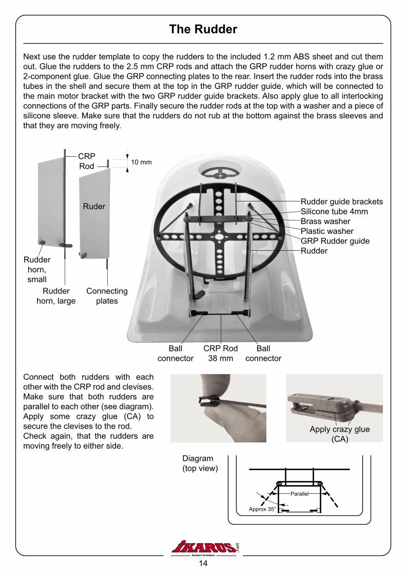
Connect both rudders with each other with the CRP rod and clevises. Make sure that both rudders are parallel to each other (see diagram). Apply some crazy glue (CA) to secure the clevises to the rod.Check again, that the rudders are moving freely to either side.
CRP Rod 38 mm
Ball connector
Rudder guide bracketsSilicone tube 4mmBrass washerPlastic washerGRP Rudder guideRudder
Diagram (top view)
10 mm
Connecting plates
Rudder horn, small
Rudder horn, large
Ruder
CRP Rod
Apply crazy glue (CA)
Next use the rudder template to copy the rudders to the included 1.2 mm ABS sheet and cut them out. Glue the rudders to the 2.5 mm CRP rods and attach the GRP rudder horns with crazy glue or 2-component glue. Glue the GRP connecting plates to the rear. Insert the rudder rods into the brass tubes in the shell and secure them at the top in the GRP rudder guide, which will be connected to the main motor bracket with the two GRP rudder guide brackets. Also apply glue to all interlocking connections of the GRP parts. Finally secure the rudder rods at the top with a washer and a piece of silicone sleeve. Make sure that the rudders do not rub at the bottom against the brass sleeves and that they are moving freely.
Ball connector
15
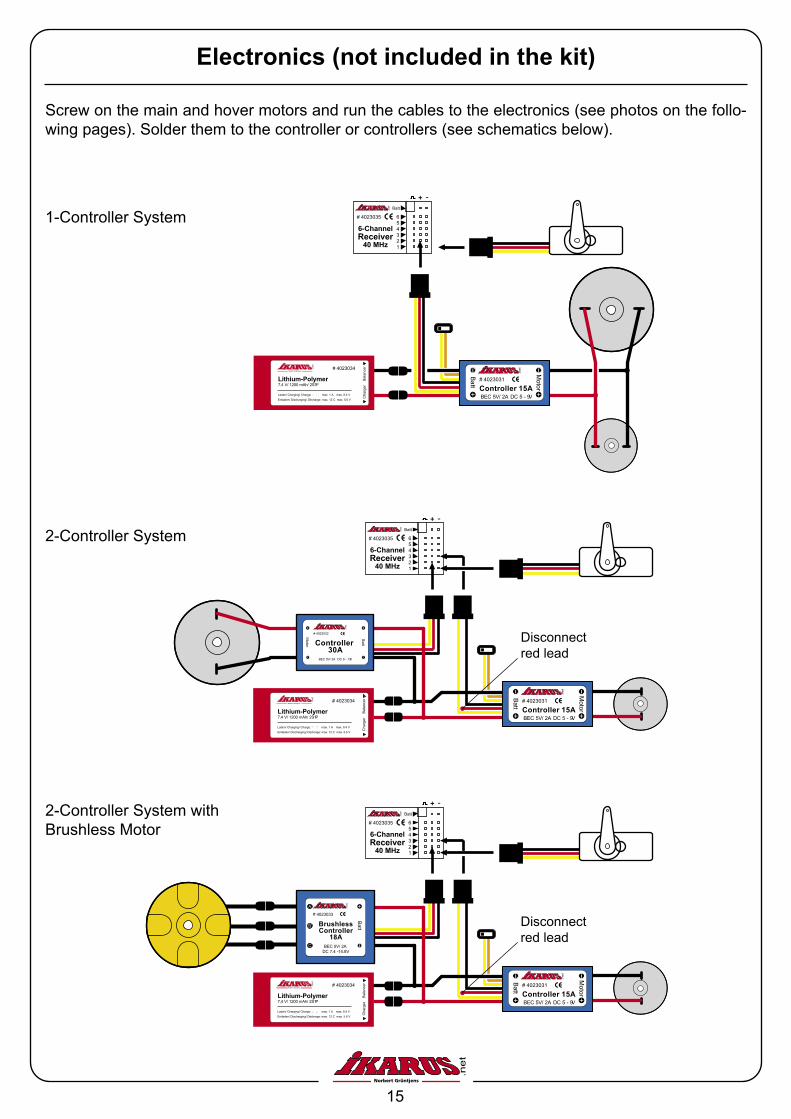
Screw on the main and hover motors and run the cables to the electronics (see photos on the follo-wing pages). Solder them to the controller or controllers (see schematics below).
Electronics (not included in the kit)
# 4023031
Controller 15A
Batt
BEC 5V/ 2A DC 5 - 9V
Motor
# 4023034
Lithium-Polymer7,4 V/ 1200 mAh/ 2S1P
Laden/ Charging/ Charge: � � max. 1 A max. 8.4 V
Entladen/ Discharging/ Décharge: max. 12 C max. 5.6 V
Bal
ance
rC
harg
er
# 4023035
Batt
654321
6-ChannelReceiver
40 MHz
1-Controller System
2-Controller System
2-Controller System with Brushless Motor
# 4023032
Controller 30A
Batt
BEC 5V/ 2A DC 9 - 13V
Motor
# 4023034
Lithium-Polymer7,4 V/ 1200 mAh/ 2S1P
Laden/ Charging/ Charge: � � max. 1 A max. 8.4 V
Entladen/ Discharging/ Décharge: max. 12 C max. 5.6 V
Bal
ance
rC
harg
er
# 4023035
Batt
654321
6-ChannelReceiver
40 MHz
# 4023031
Controller 15A
Batt
BEC 5V/ 2A DC 5 - 9V
Motor
Disconnect red lead
# 4023034
Lithium-Polymer7,4 V/ 1200 mAh/ 2S1P
Laden/ Charging/ Charge: � � max. 1 A max. 8.4 V
Entladen/ Discharging/ Décharge: max. 12 C max. 5.6 V
Bal
ance
rC
harg
er
# 4023035
Batt
654321
6-ChannelReceiver
40 MHz
# 4023031
Controller 15A
Batt
BEC 5V/ 2A DC 5 - 9V
Motor
# 4023033
BrushlessController
18A
Batt
BEC 5V/ 2A DC 7.4 -14.8V
Disconnect red lead
16
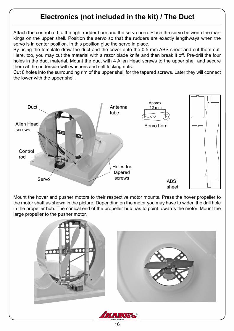
Attach the control rod to the right rudder horn and the servo horn. Place the servo between the mar-kings on the upper shell. Position the servo so that the rudders are exactly lengthways when the servo is in center position. In this position glue the servo in place.By using the template draw the duct and the cover onto the 0.5 mm ABS sheet and cut them out. Here, too, you may cut the material with a razor blade knife and then break it off. Pre-drill the four holes in the duct material. Mount the duct with 4 Allen Head screws to the upper shell and secure them at the underside with washers and self locking nuts.Cut 8 holes into the surrounding rim of the upper shell for the tapered screws. Later they will connect the lower with the upper shell.
Servo
Antenna tube
Control rod
Allen Head screws
Duct
Holes for tapered screws
Electronics (not included in the kit) / The Duct
ABS sheet
Mount the hover and pusher motors to their respective motor mounts. Press the hover propeller to the motor shaft as shown in the picture. Depending on the motor you may have to widen the drill hole in the propeller hub. The conical end of the propeller hub has to point towards the motor. Mount the large propeller to the pusher motor.
Servo horn
Approx. 12 mm
17
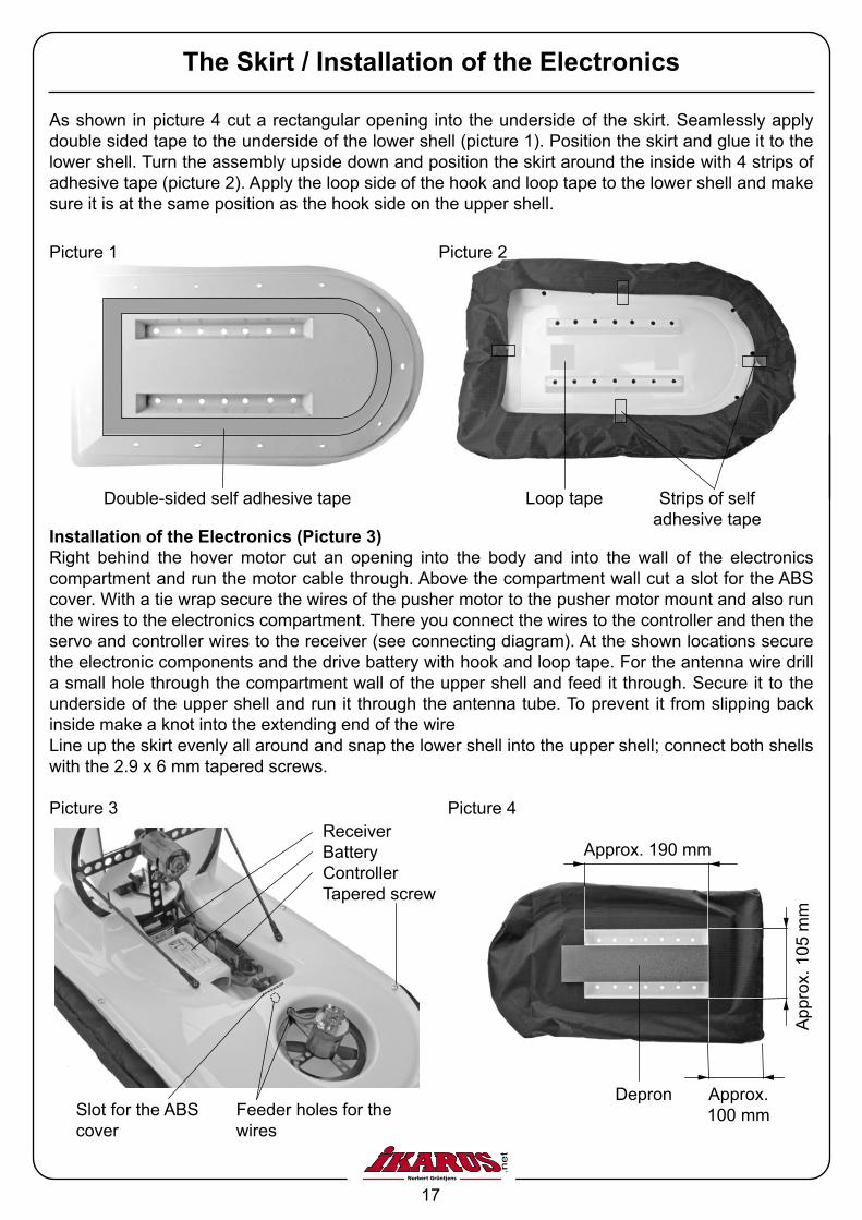
ReceiverBatteryControllerTapered screw
Picture 3
Feeder holes for the wires
Slot for the ABS cover
The Skirt / Installation of the Electronics
As shown in picture 4 cut a rectangular opening into the underside of the skirt. Seamlessly apply double sided tape to the underside of the lower shell (picture 1). Position the skirt and glue it to the lower shell. Turn the assembly upside down and position the skirt around the inside with 4 strips of adhesive tape (picture 2). Apply the loop side of the hook and loop tape to the lower shell and make sure it is at the same position as the hook side on the upper shell.
Installation of the Electronics (Picture 3)Right behind the hover motor cut an opening into the body and into the wall of the electronics compartment and run the motor cable through. Above the compartment wall cut a slot for the ABS cover. With a tie wrap secure the wires of the pusher motor to the pusher motor mount and also run the wires to the electronics compartment. There you connect the wires to the controller and then the servo and controller wires to the receiver (see connecting diagram). At the shown locations secure the electronic components and the drive battery with hook and loop tape. For the antenna wire drill a small hole through the compartment wall of the upper shell and feed it through. Secure it to the underside of the upper shell and run it through the antenna tube. To prevent it from slipping back inside make a knot into the extending end of the wire Line up the skirt evenly all around and snap the lower shell into the upper shell; connect both shells with the 2.9 x 6 mm tapered screws.
Double-sided self adhesive tape
Picture 1
Loop tape Strips of self adhesive tape
Picture 2
Depron
Picture 4
Approx. 190 mm
Approx. 100 mm
App
rox.
105
mm
18
Driving Tips
Driving a hovercraft cannot be compared to driving an RC car. As there is basically no ground contact and the model is hovering close to the ground you will have to practice controlled braking and steering. We recommend seeking an open area without any obstacles for your first drives.
If you realize that the hovercraft takes a “nose down” attitude during acceleration and therefore is being slowed down, you will need to adjust the pusher motor thrust. Turn the nuts at the pusher motor mount further onto the threaded pushrod to tilt the mount somewhat forward. If the hovercraft makes turns despite straight rudder alignment you will have to adjust the side thrust. Make this adjustment – just as with the down thrust – by turning the nuts on the threaded rod in or out. This way you twist the mount sideways.
If you want to rapidly slow down your hovercraft out of high speed you will need to give full rudder with some forward throttle. This way you start a 180° turn. The direction of movement remains unchanged for the time being. If the model floats tail first, apply forward full throttle to stop the hovercraft as fast as possible. Definitely practice this type of braking maneuver. Stopping the model by “setting it down” (switching off the hover motor) will increase wear and tear on the skirt.
We warrant the IKARUS product within the European Union for a period of 24 months. Your sales receipt is evidence of the start and finish of the warranty period. Any repairs do not extend the warranty period. If any functional, manufacturing or material defects become evident during the warranty pe-riod we will rectify them. Further claims, e.g. subsequent damage or loss are strictly excluded. There will be a 20.00 € service charge (plus return shipping charges) for repair items, which turn out to be in perfect condition. Postage must be paid for; the return shipping will also be paid for. Shipments arriving postage collect will not be accepted. We do not accept any liability for damage or loss during inbound transport.
Warranty terms
www.ikarus.net
Ikarus ModellsportIm Webertal 22D-78713 Schramberg-Waldmössingen
International Call Center: +49 (0) 74 02/ 92 91-900Fax: +49 (0) 74 02/ 92 [email protected]
19
Accessories & Replacement parts
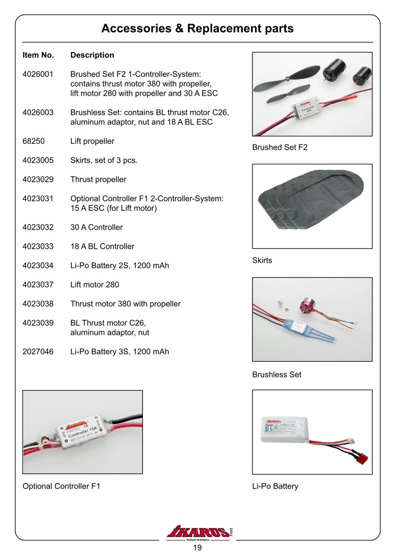
Item No. Description
4026001 Brushed Set F2 1-Controller-System: contains thrust motor 380 with propeller, lift motor 280 with propeller and 30 A ESC
4026003 Brushless Set: contains BL thrust motor C26, aluminum adaptor, nut and 18 A BL ESC
68250 Lift propeller
4023005 Skirts, set of 3 pcs.
4023029 Thrust propeller
4023031 Optional Controller F1 2-Controller-System: 15 A ESC (for Lift motor)
4023032 30 A Controller
4023033 18 A BL Controller
4023034 Li-Po Battery 2S, 1200 mAh
4023037 Lift motor 280
4023038 Thrust motor 380 with propeller
4023039 BL Thrust motor C26, aluminum adaptor, nut
2027046 Li-Po Battery 3S, 1200 mAh
Brushed Set F2
Skirts
Brushless Set
Li-Po BatteryOptional Controller F1