Embed Size (px)
Citation preview
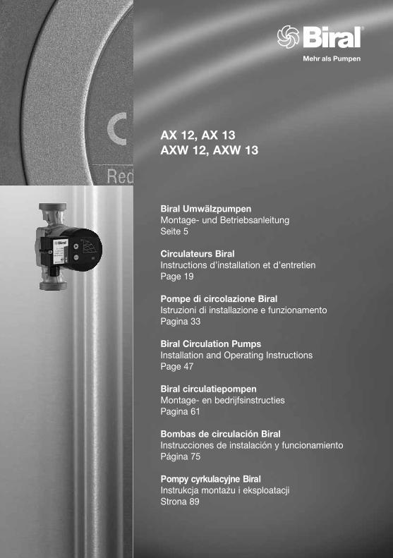
AX 12, AX 13AXW 12, AXW 13
Biral UmwälzpumpenMontage- und BetriebsanleitungSeite 5
Circulateurs BiralInstructions d’installation et d’entretienPage 19
Pompe di circolazione BiralIstruzioni di installazione e funzionamentoPagina 33
Biral Circulation PumpsInstallation and Operating InstructionsPage 47
Biral circulatiepompenMontage- en bedrijfsinstructiesPagina 61
Bombas de circulación BiralInstrucciones de instalación y funcionamientoPágina 75
Pompy cyrkulacyjne BiralInstrukcja montażu i eksploatacjiStrona 89
2
Konformitäts-Erklärung DEWir Biral AG erklären in alleiniger Verantwortung, dass die Produkte
AX 12, AX 13AXW 12, AXW 13
auf die sich diese Erklärung bezieht, mit folgenden Richtlinien des Rates zur Angleichung der Rechtsvorschriften der EG Mitgliedstaaten übereinstimmen:
– Maschinen (2006/42/EG)Norm: EN 12100-1
– Elektrische Betriebsmittel zur Verwendung innerhalb bestimmter Spannungsgrenzen (2006/95/EG)Normen: EN 60335-1, EN 60335-2-51
– Elektromagnetische Verträglichkeit (2004/108/EG)Normen: EN 61000-6-2, EN 61000-6-3
Dichiarazione di Conformità ITNoi Biral AG dichiariamo sotto la nostra esclusiva responsabilità che i prodotti
AX 12, AX 13AXW 12, AXW 13
ai quali questa dichiarazione si riferisce, sono conformi alle direttive del Consiglio, concernenti il ravvicinamento delle legislazioni degli Stati membri CE relativi a:
– Macchine (2006/42/CE)Norme: EN 12100-1
– Materiale elettrico destinato ad essere utilizzato entro certi limiti di tensione (2006/95/CE)Norme: EN 60335-1, EN 60335-2-51
– Compatibilità elettromagnetica (2004/108/CE)Norme: EN 61000-6-2, EN 61000-6-3
Declaration of Conformity ENWe Biral AG declare under our sole responsibility that the products
AX 12, AX 13AXW 12, AXW 13
to which this declaration relates, are in conformity with the Council Directives on the approximation of the laws of the EC Member States relating to:
– Machinery (2006/42/EC)Standard: EN12100-1
– Electrical equipment designed for use within certain voltage limits (2006/95/EC)Standards: EN 60335-1, EN 60335-2-51
– Electromagnetic compatibility (2004/108/EC)Standards: EN 61000-6-2, EN 61000-6-3
Déclaration de conformité FRNous Biral AG déclarons sous notre seule responsabilité que les produits
AX 12, AX 13AXW 12, AXW 13
auxquels se réfère cette déclaration sont conformes aux Directives du Conseil concernant le rapprochement des législations des Etats membres CE relatives à:
– Machines (2006/42/CE)Norme: EN 12100-1
– Matériel électrique destiné à employer dans certaines limites de tension (2006/95/CE)Normes: EN 60335-1, EN 60335-2-51
– Compatibilité électromagnétique (2004/108/CE)Normes: EN 61000-6-2, EN 61000-6-3
3
Declaración de conformidad ESNosotros Biral AG declaramos bajo nuestra única responsabilidad que los productos
AX 12, AX 13AXW 12, AXW 13
a los cuales se refiere esta declaración son conformes con las Directivas del Consejo relativas a la aproximación de las legislaciones de los Estados Miembros de la CE sobre
– Máquinas (2006/42/CE)Norma: EN 12000-1
– Material eléctrico destinado a utilizarse con determinadas límites de tensión (2006/95/CE)Normas: EN 60335-1, EN 60335-2-51
– Compatibilidad electromagnética (2004/108/CE)Normas: EN 61000-6-2, EN 61000-6-3
Conformiteitverklaring NLWij Biral AG verklaren geheel onder eigen verantwoordelijkheid dat de produkten
AX 12, AX 13AXW 12, AXW 13
waarop deze verklaring betrekking heeft in overeenstemming zijn met de Richtlijnen van de Raad inzake de onderlinge aanpassing van de wetgevingen van de EG Lid-Staten betreffende
– Maschines (2006/42/EG)Normen: EN 12100-1
– Elektrisch materiaal bestemd voor gebruik binnen bepaalde spanningsgrenzen (2006/95/EG)Normen: EN 60335-1, EN 60335-2-51
– Elektromagnetische compatibiliteit (2004/108/EG)Normen: EN 61000-6-2, EN 61000-6-3
Münsingen, 1st January 2011
Biral AG, Südstrasse 10, CH-3110 MünsingenPhone: +41(0) 31 720 90 00, Fax +41(0) 31 720 94 42Mail: [email protected], www.biral.ch
Authorized representative for the completion of the technical documentation:
Adrian HunzikerSüdstr. 10, CH-3110 Münsingen/Schweiz
Peter GygerTechnical Director
Deklaracja zgodności PLMy - firma Biral AG - oświadczamy na własną odpowiedzialność, że produkty
AX 12, AX 13AXW 12, AXW 13
do których odnosi się niniejsza deklaracja, są zgodne z dyrektywami Rady w sprawie zbliżenia ustawodawstw Państw Członkowskich UE:
– Maszyny (2006/42/EG)Norma: EN 12100-1
– Sprzęt elektryczny przewidziany do stosowania w określonych granicach napięcia (2006/95/EG)Normy: EN 60335-1, EN 60335-2-51
– Kompatybilność elektromagnetyczna (2004/108/EG)Normy: EN 61000-6-2, EN 61000-6-3
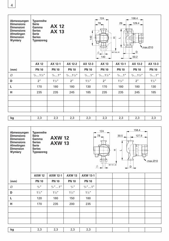
AX 12 AX 12-1 AX 12-2 AX 12-3 AX 13 AX 13-1 AX 13-2 AX 13-3
(mm) PN 10 PN 10 PN 10 PN 10 PN 10 PN 10 PN 10 PN 10
∅ 3/4…11/2” 3/4…1” 3/4…11/2” 3/4…1” 3/4…11/2” 3/4…1” 3/4…11/2” 3/4…1”
D 2” 11/2” 2” 11/2” 2” 11/2” 2” 11/2”
L 170 180 180 130 170 180 180 130
H 235 235 245 185 235 235 245 185
4
Abmessungen TypenreiheDimensions SérieDimensioni GammaDimensions SeriesAfmetingen SerieDimension SeriesWymiary Typoszereg
AX 12AX 13
kg 2,3 2,3 2,3 2,3 2,3 2,3 2,3 2,3
78
124
H
140
140
961156_00
L
29 129.4
158.4
D
50.2
max.Ø10
AXW 12 AXW 12-1 AXW 13 AXW 13-1
(mm) PN 10 PN 10 PN 10 PN 10
∅ 3/4” 3/4”…1” 3/4” 3/4”…1”
D 11/4” 11/2” 11/4” 11/2”
L 120 180 150 180
H 170 235 200 235
Abmessungen TypenreiheDimensions SérieDimensioni GammaDimensions SeriesAfmetingen SerieDimension SeriesWymiary Typoszereg
AXW 12AXW 13
kg 2,3 2,3 2,3 2,3
78
124
H
961157_00
127.9
L
D
158.4
30.5
max.Ø10
5
Inhaltsverzeichnis
1. Sicherheitshinweise Seite 61.1 Allgemeines 61.2 Kennzeichnung von Hinweisen 61.3 Personalqualifikation und -schulung 61.4 Gefahren bei Nichtbeachtung
der Sicherheitshinweise 61.5 Sicherheitsbewusstes Arbeiten 71.6 Sicherheitshinweise für den Betreiber/Bediener 71.7 Sicherheitshinweise für Montage-,
Wartungs- und Inspektionsarbeiten 71.8 Eigenmächtiger Umbau und Ersatzteilherstellung 71.9 Unzulässige Betriebsweisen 7
2. Transport/Lagerung 7
3. Verwendungszweck 83.1 Fördermedium 83.2 Betriebstemperatur/Betriebsdruck 8
4. Montage 84.1 Durchspülen der Heizungsanlage 84.2 Frostschutzmittel (sofern erforderlich) 84.3 Einbau 84.4 Montageposition 94.5 Rückschlagventil 94.6 Mindestdruck 9
5. Elektrischer Anschluss 105.1 Anschlussklemmen 115.2 Anschlussschema Standardausführung 11
6. Einstellungen 126.1 Einstellung der Regelungsart und Förderhöhe 126.2 Werkseitige Einstellung der Pumpe 136.3 Regelkennlinie AX 12, AXW 12 136.4 Regelkennlinie AX 13, AXW 13 13
7. Inbetriebnahme/Betriebskontrolle 147.1 Allgemeines 147.2 Entlüften 147.3 Betriebskontrolle 147.4 Deblockieren 14
8. Wartung, Service 14
9. Störungsübersicht 15
10. Zubehör 1610.1 Wärmedämmschalen 1610.2 Absperrset 16
11. Technische Daten 17
12. Entsorgung 17
deutsch
6
Dieses Symbol steht für Warnung vorgefährlicher elektrischer Spannung.«Sicherheitszeichen nach DIN 4844-W8».
Die in dieser Montage- und Betriebsanleitungenthaltenen Sicherheitshinweise, die bei Nicht-beachtung Gefährdungen für Personen hervor-rufen können, sind mit allgemeinem Gefahren-symbol «Sicherheitszeichen nach DIN 4844-W9»besonders gekennzeichnet.
1. Sicherheitshinweise
1.1 AllgemeinesDiese Montage- und Betriebsanleitung enthält grundlegendeHinweise, die bei Aufstellung, Betrieb und Wartung zu beachtensind. Sie ist daher unbedingt vor Montage und Inbetriebnahmevom Monteur sowie dem zuständigen Fachpersonal/Betreiberzu lesen. Sie muss ständig am Einsatzort der Anlage verfügbarsein.Es sind nicht nur die unter diesem Abschnitt «Sicherheits-hinweise» aufgeführten, allgemeinen Sicherheitshinweise zubeachten, sondern auch die unter den anderen Abschnitten ein-gefügten, speziellen Sicherheitshinweise.
1.2 Kennzeichnung von Hinweisen
Dieses Symbol finden Sie bei Sicherheits-hinweisen, deren Nichtbeachtung Gefahren für die Maschine und deren Funktionen hervorrufen kann.
Achtung
Direkt an der Anlage angebrachte Hinweise wie zum Beispiel
– Drehrichtungspfeil– Kennzeichen für Fluidanschlüsse
müssen unbedingt beachtet und in vollständig lesbaremZustand gehalten werden.
1.3 Personalqualifikation und -schulungDas Personal für Montage, Bedienung, Wartung und Inspektionmuss die entsprechende Qualifikation für diese Arbeiten auf-weisen. Verantwortungsbereich, Zuständigkeit und die Über-wachung des Personals müssen durch den Betreiber genaugeregelt sein.
1.4 Gefahren bei Nichtbeachtung der SicherheitshinweiseDie Nichtbeachtung der Sicherheitshinweise kann sowohl eineGefährdung für Personen als auch für die Umwelt und Anlage zurFolge haben. Die Nichtbeachtung der Sicherheitshinweise kannzum Verlust jeglicher Schadenersatzansprüche führen.
deutsch
7
Im einzelnen kann Nichtbeachtung beispielsweise folgende Gefährdungen nach sich ziehen:– Versagen wichtiger Funktionen in der Anlage– Versagen vorgeschriebener Methoden
zur Wartung und Instandhaltung– Gefährdung von Personen durch elektrische
und mechanische Einwirkungen
1.5 Sicherheitsbewusstes ArbeitenDie in dieser Montage- und Betriebsanleitung aufgeführtenSicherheitshinweise, die bestehenden nationalen Vorschriftenzur Unfallverhütung sowie eventuelle interne Arbeits-, Betriebs-und Sicherheitsvorschriften des Betreibers, sind zu beachten.
1.6 Sicherheitshinweise für den Betreiber/BedienerGefährdungen durch elektrische Energie sind auszuschliessen(Einzelheiten hierzu siehe zumBeispiel in den Vorschriften desNIN (CENELEC) und der örtlichen Energieversorgungs-unternehmen).
1.7 Sicherheitshinweise für Montage-, Wartungs- und Inspektionsarbeiten
Der Betreiber hat dafür zu sorgen, dass alle Montage-,Wartungs- und Inspektionsarbeiten von autorisiertem und qualifiziertem Fachpersonal ausgeführt werden, das sich durcheingehendes Studium der Montage- und Betriebsanleitung aus-reichend informiert hat.Grundsätzlich sind arbeiten an der Anlage nur im Stillstanddurchzuführen.Unmittelbar nach Abschluss der Arbeiten müssen alleSicherheits- und Schutzeinrichtungen wieder angebracht bzw.in Funktion gesetzt werden.Vor der Wiederinbetriebnahme sind die im Abschnitt «Elektrischer Anschluss» aufgeführten Punkte zu beachten.
1.8 Eigenmächtiger Umbau und ErsatzteilherstellungUmbau oder Veränderungen an Pumpen sind nur nachAbsprache mit dem Hersteller zulässig. Originalersatzteile undvom Hersteller autorisiertes Zubehör dienen der Sicherheit. Die Verwendung anderer Teile kann die Haftung für die darausentstehenden Folgen aufheben.
1.9 Unzulässige BetriebsweisenDie Betriebssicherheit der gelieferten Pumpen ist nur bei bestimmungsgemässer Verwendung entsprechend Abschnitt «Verwendungszweck» der Montage- und Betriebsanleitunggewährleistet. Die in den technischen Daten angegebenenGrenzwerte dürfen auf keinen Fall überschritten werden.
deutsch
2. Transport/Lagerung
Die Pumpen werden vom Werk in einer zweckmässigenVerpackung geliefert.
deutsch8
3. Verwendungszweck
Die Biral-Umwälzpumpen der Typenreihe
AX 12, AX 13, AXW 12, AXW 13
umfasst einen Permanentmagnet-Motor mit Spaltrohr und einen integrierten Frequenzumformer mit Konstantdruck-,Proportionaldruck- und Konstantdrehzahlregelung.Die Pumpe wird verwendet zur Förderung von Flüssigkeiten in:– Warmwasser-Heizungsanlagen– geschlossenen industriellen Umwälzsystemen– Trinkwasseranlagen (AXW)
3.1 FördermediumIn Heizungsanlagen soll das Fördermedium den Anforderungenvon Heizungswasser gemäss VDI 2035 entsprechen. Wasser-/Glykol-Gemisch zulässig bis 50% Glykolanteil.
4. Montage
4.1 Durchspülen der Heizungsanlage (bei ausgebauter Pumpe)Um unliebsame Betriebsunterbrüche und das Nichtanlaufen der Pumpe nach längeren Stillstandzeiten zu vermeiden, empfehlen wir, bei einer neu installierten oder umgebautenHeizung die Anlage nach dem ersten Aufheizen zu entleeren, gut durchzuspülen und wieder zu füllen.Die Anlage muss dem Stand der Technik entsprechen. (Platzierung Expansionsgefäss bzw. Sicherheitsvorlauf).
4.2 Frostschutzmittel (sofern erforderlich)Wichtig: Spülen Sie das Leitungsnetz besonders gut durch, bevor das Frostschutz-Gemisch eingefüllt wird. Befolgen Sie die Anweisungen des Frostschutzlieferanten in Bezug auf Mischenund Einfüllen sowie Materialwahl im Leitungs- und Apparatenetz(Korrosionsschutz beachten!).Wasser-/Glykol-Gemisch bis 50% Glykolanteil zulässig.Ab 10% Glykolanteil Förderdaten der Pumpen entsprechend korrigieren.
4.3 EinbauEinbau erst nach Abschluss aller Schweiss- und Lötarbeiten an der Anlage. Tropfwasser auf dem Pumpenmotor, speziell auf der Elektronik unbedingt vermeiden. Das Pumpengehäuse spannungsfrei in die Anlage einbauen.
Es dürfen keine brennbaren oder explosiven Flüssigkeiten gefördert werden.Die Flüssigkeit darf keine Feststoffe, Fasern oder Mineralöle enthalten.
3.2 Betriebstemperatur/BetriebsdruckZulässige Wassertemperatur: +15 °C bis +110 °CZulässiger Betriebsdruck: max. 10 barUmgebungstemperatur: max. 40 °C
Einsatz in Trinkwasseranlagen:Zulässige Wassertemperatur: +15 °C bis 85 °CZulässige Wasserhärte: max. 35 °fH (=20 °dH)
(Wassertemperatur unter 65 °C)max. 25 °fH (=14 °dH) (Wassertemperatur unter 85 °C)
Weitere Angaben siehe Kapitel 11.

4.4 MontagepositionLieferzustandKabelverschraubung links
DurchflussrichtungDer Pfeil auf dem Pumpen-gehäuse zeigt dieDurchflussrichtung an.
Klemmenkasten-PositionVor der Montage der Pumpekann der Klemmenkastenjeweils um 90° gedreht werden. Hierzu die 4Schrauben des Gehäuseslösen und den Motorkopf in die zulässige Klemmen-kasten-Position drehen.Dichtung zwischen Motor und Pumpengehäuse nicht verschieben oderbeschädigen.Nach dem Einsetzen derSchrauben diese übers Kreuzanziehen.Der Pfeil auf dem Pumpen-gehäuse zeigt die Durch-flussrichtung an. Die Welle muss immer waagrecht sein, nie senkrecht.
4.5 RückschlagventilFalls ein Rückschlagventil montiert ist, muss die Pumpe so eingestellt werden (siehe Punkt 5.4.2), dass der minimaleFörderdruck der Pumpe jederzeit den Schliessdruck des Ventilsübersteigt.
Absperrschieber vor und nach der Pumpe einbauen.Damit wird bei einem möglichen Austausch der Pumpe ein Ablassen und Wiederauffüllen der Anlage vermieden.
deutsch9
961082_00
961083_00
961084_00
4.6 MindestdruckDer Mindestdruck am Pumpensaugstutzen bei 75°Czur sicheren Schmierung der Gleitlager:
Die Werte gelten bis 500 m über Meeresspiegel.Zuschlag für grössere Höhen:0,01 bar pro 100 m Höhenzuwachs
bei 75 °C 0,05 bar90 °C 0,30 bar
110 °C 1,10 bar
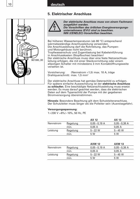
Der elektrische Anschluss muss von einem Fachmannausgeführt werden.Die Vorschriften des örtlichen Energieversorgungs-unternehmens (EVU) sind zu beachten.NIN (CENELEC)-Vorschriften beachten.
Bei höheren Wassertemperaturen (ab 80 °C) entsprechend wärmebeständige Anschlussleitung verwenden.Die Anschlussleitung darf die Rohrleitung, das Pumpen- und Motorgehäuse nicht berühren.Tropfwasserschutz und Zugentlastung bei Kabeleinführung in Anschlusskasten (Stopfbuchse) beachten!Der elektrische Anschluss muss über eine feste Netzanschluss-leitung erfolgen, die mit einer Steckvorrichtung oder einem allpoligen Schalter mit mindestens 3 mm Kontaktöffnungsweiteversehen ist.
Vorsicherung: (Nennstrom ×1,5) max. 10 A, trägeDrahtquerschnitt: max. 1,5 mm2
Der elektrische Anschluss hat gemäss Datenschild zu erfolgen.Für spätere einfache Auswechslung ist der elektrische Anschlusszu schlaufen. Eine beschädigte Netzanschlussleitung muss ersetztwerden. Es muss darauf geachtet werden, dass die elektrischenDaten auf dem Typenschild der Pumpe mit der gegebenenStromversorgung übereinstimmen.
Hinweis: Besondere Beachtung gilt dem Schutzleiteranschluss.Der Schutzleiter muss länger als die Polleiter sein (Ausreissgefahr).
Versorgungsspannung:
1× 230 V +6%/–10%, 50 Hz, PE
961085_00
5. Elektrischer Anschluss
AX 12 AX 13
Nennstrom Regelung 0,05 – 0,19 A 0,05 – 0,38 Amin. 0,05 A 0,05 A
Leistung Regelung 5 – 22 W 5 – 45 Wmin. 5 W 5 W
AXW 12 AXW 13
Nennstrom Regelung 0,05 – 0,19 A 0,05 – 0,38 Amin. 0,05 A 0,05 A
Leistung Regelung 5 – 22 W 5 – 45 Wmin. 5 W 5 W
deutsch10
961086_00
N L
Speisung ~ 1x230V
Vorsicherung10A
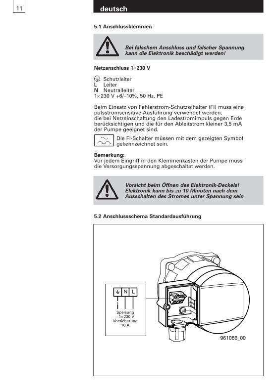
5.2 Anschlussschema Standardausführung
Speisung~1× 230 V
Vorsicherung10 A
Netzanschluss 1×230 V
SchutzleiterL LeiterN Neutralleiter1× 230 V +6/–10%, 50 Hz, PE
Beim Einsatz von Fehlerstrom-Schutzschalter (FI) muss eine pulsstromsensitive Ausführung verwendet werden, die bei Netzeinschaltung den Ladestromimpuls gegen Erde berücksichtigen und die für den Ableitstrom kleiner 3,5 mA der Pumpe geeignet sind.
Die FI-Schalter müssen mit dem gezeigten Symbol gekennzeichnet sein.
Bemerkung:Vor jedem Eingriff in den Klemmenkasten der Pumpe muss die Versorgungsspannung abgeschaltet werden.
Bei falschem Anschluss und falscher Spannung kann die Elektronik beschädigt werden!
5.1 Anschlussklemmen
deutsch11
Vorsicht beim Öffnen des Elektronik-Deckels!Elektronik kann bis zu 10 Minuten nach demAusschalten des Stromes unter Spannung sein

12 deutsch
6. Einstellungen
6.1 Einstellung der Regelungsart und Förderhöhe
Pos. Beschreibung
A BedientastaturB Firmenschild
9610
87_0
0
B A 5 Automatische Nachtabsenkung Aut.Geht die Vorlauftemperatur in der Anlage um 10 bis 15 °C zurück (min. 0.1 °C/min), wird die Pumpenleistung nach zirka 2 Stunden auf «min » abgesenkt.
Steigt die Vorlauftemperatur um 10 °C wird sofort auf Regelbetrieb umgeschaltet.LED leuchtet: Funktion «Automatische Nachtabsenkung» ist eingeschaltet.
Bemerkung:– Bei Konstantdrehzahl I, II oder III ist die automatische
Nachtabsenkung deaktiviert.
Damit die automatische Nachtabsenkung einwandfrei funktioniert, müssen folgende Bedingungen erfüllt sein:– Die Pumpe muss im Vorlauf der Heizung installiert sein.
Sie funktioniert nicht im Rücklauf.– Die Heizung muss über eine Regelung
der Mediumtemperatur verfügen.
1 Bedientaste
2 Geregelter Betrieb: Proportionaldruck (pp)Sinnvoll in folgenden Anlagen:– Zweirohrsystemen mit thermischen Ventilen und
– langen Leitungsstrecken– Ventilen mit grossem Arbeitsbereich– Hohem Druckverlust
– Primärkreispumpen mit hohem Druckverlust
3 Geregelter Betrieb: Konstantdruck (cp)Sinnvoll in folgenden Anlagen:– Zweirohrsystemen mit thermischen Ventilen und
– Förderhöhe <2m– Natürlicher Umwälzung
(ehemalige Schwerkraftheizung)– mit sehr geringem Druckverlust– Primärkreispumpen in Anlagen
mit geringem Druckverlust– Fussbodenheizung mit Thermostatventilen – Einrohrheizungen
4 Ungeregelter Betrieb: Konstantdrehzahl (cs)Sinnvoll für Anlagen mit konstantem Volumenstrom:Klimaanwendungen, Wärmepumpen, Kesselspeispumpenetc.
1
5 6
2 3 4
6 Die Anzeige gibt bei eingeschaltetem Netz die aktuelle Leistungsaufnahme der Pumpe an.Eine Fehlfunktion der Pumpe wird mit «- -» angezeigt.Behebung siehe Abschnitt 9 (Störungsübersicht)
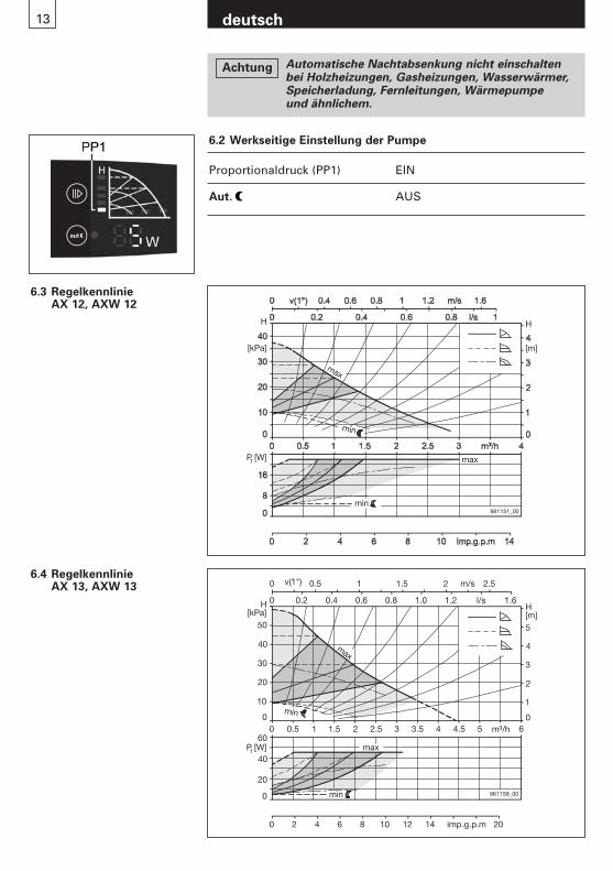
6.3 RegelkennlinieAX 12, AXW 12
13 deutsch
6.4 RegelkennlinieAX 13, AXW 13
0
0 0
1
H[m]
0
20
0
0
0
10
imp.g.p.m
961158_00
max
min
min
max
20
30
40
50
2
3
4
5
H[kPa]
P [W]
0.5 1 1.5 2 2.5 3 3.5 4 4.5 5 m³/h 6
0.2 0.4 0.6 0.8 1.0 1.2 l/s 1.6
v(1") 0.5 1 1.5 2 2.5
2 4 6 8 10 12 14 20
1
40
60
m/s
H
[m]
max
H
[kPa]
P [W]1
961151_00
min
min
max
6.2 Werkseitige Einstellung der Pumpe
Proportionaldruck (PP1) EIN
Aut. AUS
Automatische Nachtabsenkung nicht einschalten bei Holzheizungen, Gasheizungen, Wasserwärmer, Speicherladung, Fernleitungen, Wärmepumpe und ähnlichem.
Achtung
deutsch14
7. Inbetriebnahme/Betriebskontrolle
7.1 Allgemeines Anlage ohne Pumpe gründlich spülen. Siehe Abschnitt 4.Die Anlage sachgemäss füllen und entlüften.Die Pumpe nur bei gefüllter Anlage in Betrieb nehmen.Versorgungsspannung einschalten.
7.2 EntlüftenDas Entlüften der Pumpe, speziell der Motorraum, erfolgt nach kurzer Betriebsdauer selbsttätig. Kurzzeitiger (max. 2 min) Trockenlauf schadet der Pumpe nicht.Es empfiehlt sich, die Pumpe kurz auf «max» laufen zu lassen, um eine schnelle Entlüftung des Systems zu gewährleisten.
7.3 BetriebskontrolleEs muss immer eine LED leuchten und die aktuelleLeistungsaufnahme muss angezeigt werden. (Siehe Abschnitt 6.1 Pos 6)
7.4 DeblockierenNicht notwendig. Motor startet mit hohem Anzugsmoment und verfügt über ein internes Deblockadeprogramm.
Es besteht Verbrühungsgefahr
Vor Beginn der Wartungsarbeiten die Pumpe unbedingt ausser Betrieb nehmen, allpolig vom Netztrennen und gegen Wiedereinschalten sichern. Ausführung nur durch Fachpersonal.
Betriebsanleitung beachten. Arbeiten nur im Stillstand der Anlage durchführen.Pumpe spannungslos machen.
Sicherung ausschalten und Warntafel anbringen.
Verbrühungsgefahr durch austretendes Medium.
Verbrennungsgefahr durch heisse Oberflächen.
8. Wartung, Service
Die Pumpe darf nicht ohne Wasser betrieben werden!
Achtung
deutsch15
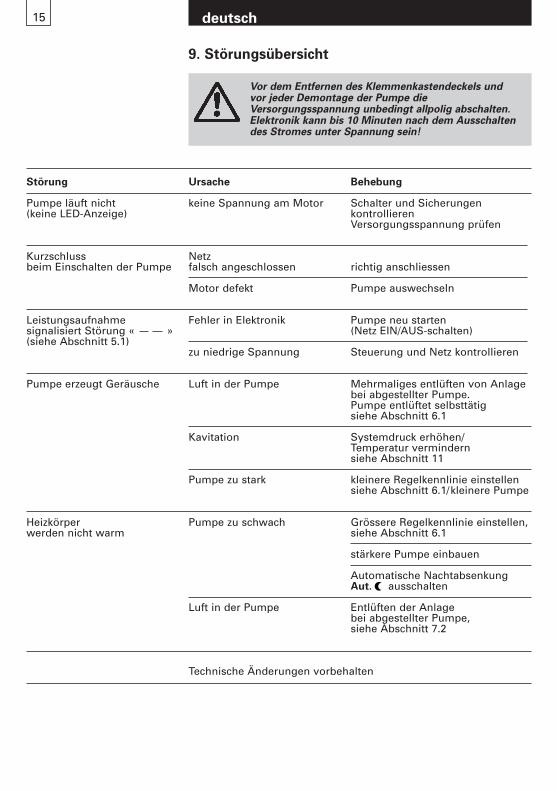
9. Störungsübersicht
Vor dem Entfernen des Klemmenkastendeckels undvor jeder Demontage der Pumpe dieVersorgungsspannung unbedingt allpolig abschalten.Elektronik kann bis 10 Minuten nach dem Ausschaltendes Stromes unter Spannung sein!
Störung Ursache Behebung
Pumpe läuft nicht keine Spannung am Motor Schalter und Sicherungen(keine LED-Anzeige) kontrollieren
Versorgungsspannung prüfen
Kurzschluss Netzbeim Einschalten der Pumpe falsch angeschlossen richtig anschliessen
Motor defekt Pumpe auswechseln
Leistungsaufnahme Fehler in Elektronik Pumpe neu starten signalisiert Störung « » (Netz EIN/AUS-schalten) (siehe Abschnitt 5.1)
zu niedrige Spannung Steuerung und Netz kontrollieren
Pumpe erzeugt Geräusche Luft in der Pumpe Mehrmaliges entlüften von Anlage bei abgestellter Pumpe. Pumpe entlüftet selbsttätigsiehe Abschnitt 6.1
Kavitation Systemdruck erhöhen/Temperatur vermindernsiehe Abschnitt 11
Pumpe zu stark kleinere Regelkennlinie einstellen siehe Abschnitt 6.1/kleinere Pumpe
Heizkörper Pumpe zu schwach Grössere Regelkennlinie einstellen,werden nicht warm siehe Abschnitt 6.1
stärkere Pumpe einbauen
Automatische Nachtabsenkung Aut. ausschalten
Luft in der Pumpe Entlüften der Anlage bei abgestellter Pumpe, siehe Abschnitt 7.2
Technische Änderungen vorbehalten

deutsch16
10. Zubehör
AX
12
AX
12-1
AX
12-2
AX
12-3
AX
12-4
AX
13
AX
13-1
AX
13-2
AX
13-3
AX
13-4
AX
W 1
2
AX
W 1
2-1
AX
W 1
3
AX
W 1
3-1 Weitere
AngabensieheKapitel
Wärmedämmschalen 3 3 3 – – 3 3 3 – – – l – l 10.1
Absperrset – – – – – – – – – – 3 – 3 – 10.2
3 Standard (im Lieferumfang enthalten)
l Optional erhältlich
– nicht erhältlich
G 1
"
G 1
1/4
"
40
961395_00
G 1"
G 1"961397_00
AX
W 1
2: 2
17 m
m, A
XW
13:
247
mm
Kugelabsperrhahn 1” Aussengewinde mit Überwurfmutter 11/4” InnengewindeHöhe 53 mm
G 1
"
G 1
1/4
"
53
961396_00
Rückschlagventil(Schwerkraftbremse)1” Aussengewinde mit Überwurfmutter 11/4” InnengewindeHöhe 40 mmÖffnungsdruck: 20–35 mbar
961194_00
BB1 T1
T
H
10.1 Wärmedämmschalenfür Medientemperatur von 15 °C bis 110 °CBrandschutzklasse B2 nach DIN 4102
Typ B B1 H T T1
WD1 140 70 140 90 50
10.2 Absperrsetbestehend aus Rückschlagventil und Kugelabsperrhahn
961394_00
11. Technische Daten
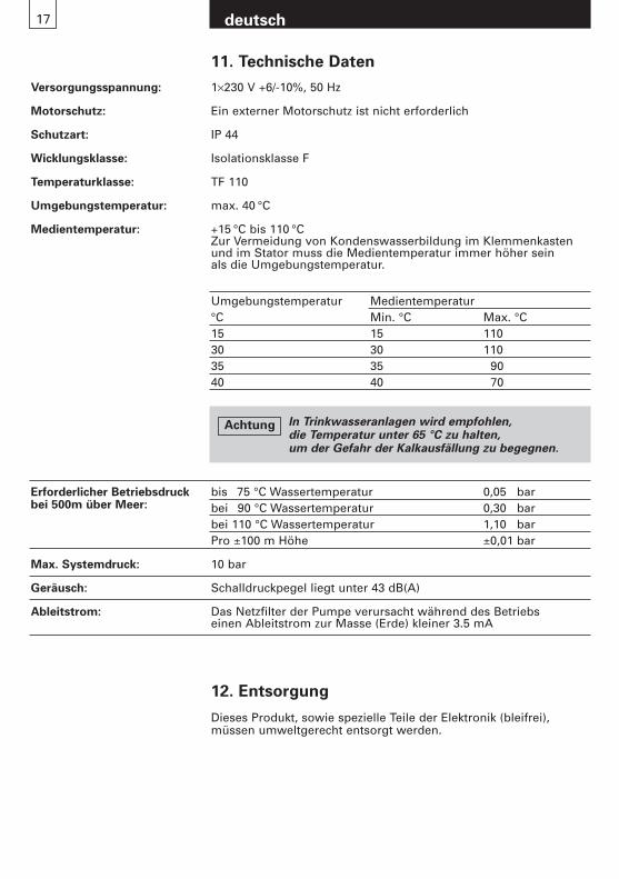
Versorgungsspannung: 1×230 V +6/-10%, 50 Hz
Motorschutz: Ein externer Motorschutz ist nicht erforderlich
Schutzart: IP 44
Wicklungsklasse: Isolationsklasse F
Temperaturklasse: TF 110
Umgebungstemperatur: max. 40 °C
Medientemperatur: +15 °C bis 110 °CZur Vermeidung von Kondenswasserbildung im Klemmenkasten und im Stator muss die Medientemperatur immer höher sein als die Umgebungstemperatur.
bis 75 °C Wassertemperatur 0,05 barbei 90 °C Wassertemperatur 0,30 barbei 110 °C Wassertemperatur 1,10 barPro ±100 m Höhe ±0,01 bar
Max. Systemdruck: 10 bar
Geräusch: Schalldruckpegel liegt unter 43 dB(A)
Ableitstrom: Das Netzfilter der Pumpe verursacht während des Betriebs einen Ableitstrom zur Masse (Erde) kleiner 3.5 mA
Erforderlicher Betriebsdruckbei 500m über Meer:
Umgebungstemperatur Medientemperatur°C Min. °C Max. °C15 15 11030 30 11035 35 9040 40 70
In Trinkwasseranlagen wird empfohlen, die Temperatur unter 65 °C zu halten, um der Gefahr der Kalkausfällung zu begegnen.
Achtung
12. Entsorgung
Dieses Produkt, sowie spezielle Teile der Elektronik (bleifrei),müssen umweltgerecht entsorgt werden.
deutsch17

Sommaire
1. Consignes de sécurité page 201.1 Généralités 201.2 Symboles de sécurité utilisés dans la présente notice 201.3 Qualification et formation du personnel 201.4 Risques et dangers en cas de non observation
des consignes de sécurité 201.5 Observation des règles de sécurité 211.6 Consignes de sécurité à l’intention
de l’utilisateur/de l’opérateur 211.7 Consignes de sécurité relatives au montage,
à l’entretien et à la révision 211.8 Modifications et pièces de rechange 211.9 Conformité d’utilisation 21
2. Transport et stockage 21
3. But d’utilisation 223.1 Fluide transporté 223.2 Température et pression de service 22
4. Montage 224.1 Rinçage de l’installation de chauffage 224.2 Antigel 224.3 Montage 224.4 Position de montage 234.5 Clapet de retenue 234.6 Pression minimale 23
5. Raccordement électrique 245.1 Bornes de raccordement 255.2 Schéma de raccordement en exécution standard 25
6. Réglages 266.1 Réglage de la régulation et du débit volumique 266.2 Réglages d’usine de la pompe 276.3 Caractéristique de réglage AX 12, AXW 12 276.4 Caractéristique de réglage AX 13, AXW 13 27
7. Mise en service/contrôle de fonctionnement 287.1 Généralités 287.2 Purge d’air 287.3 Contrôle de fonctionnement 287.4 Déblocage 28
8. Entretien, service 28
9. Résumé des dérangements 29
10. Accessoires 3010.1 Coquilles d’isolation thermique 3010.2 Kit d’isolementd 30
11. Caractéristiques techniques 31
12. Elimination 31
19 français
20
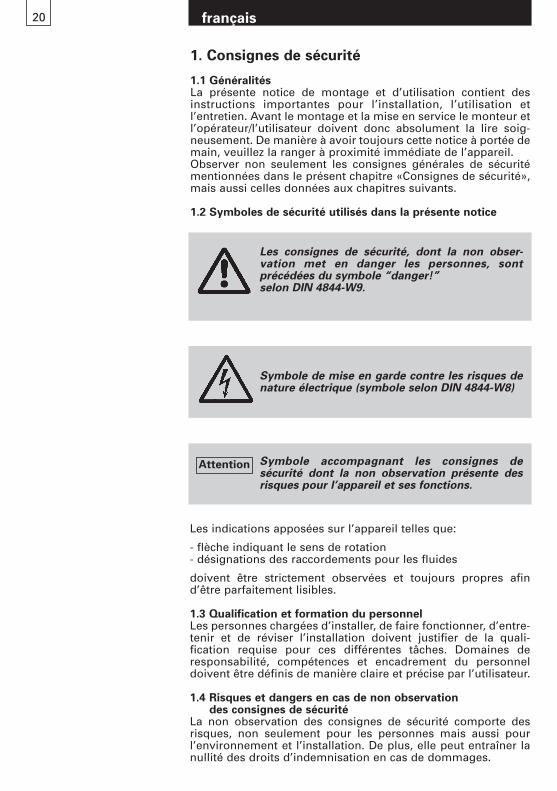
1. Consignes de sécurité
1.1 GénéralitésLa présente notice de montage et d’utilisation contient desinstructions importantes pour l’installation, l’utilisation et l’entretien. Avant le montage et la mise en service le monteur etl’opérateur/l’utilisateur doivent donc absolument la lire soig-neusement. De manière à avoir toujours cette notice à portée demain, veuillez la ranger à proximité immédiate de l’appareil.Observer non seulement les consignes générales de sécuritémentionnées dans le présent chapitre «Consignes de sécurité»,mais aussi celles données aux chapitres suivants.
1.2 Symboles de sécurité utilisés dans la présente notice
Les indications apposées sur l’appareil telles que:
- flèche indiquant le sens de rotation- désignations des raccordements pour les fluides
doivent être strictement observées et toujours propres afin d’être parfaitement lisibles.
1.3 Qualification et formation du personnelLes personnes chargées d’installer, de faire fonctionner, d’entre-tenir et de réviser l’installation doivent justifier de la quali-fication requise pour ces différentes tâches. Domaines de responsabilité, compétences et encadrement du personnel doivent être définis de manière claire et précise par l’utilisateur.
1.4 Risques et dangers en cas de non observation des consignes de sécurité
La non observation des consignes de sécurité comporte des risques, non seulement pour les personnes mais aussi pourl’environnement et l’installation. De plus, elle peut entraîner lanullité des droits d’indemnisation en cas de dommages.
Symbole de mise en garde contre les risques denature électrique (symbole selon DIN 4844-W8)
Les consignes de sécurité, dont la non obser-vation met en danger les personnes, sont précédées du symbole “danger!” selon DIN 4844-W9.
Symbole accompagnant les consignes de sécurité dont la non observation présente des risques pour l’appareil et ses fonctions.
Attention
français
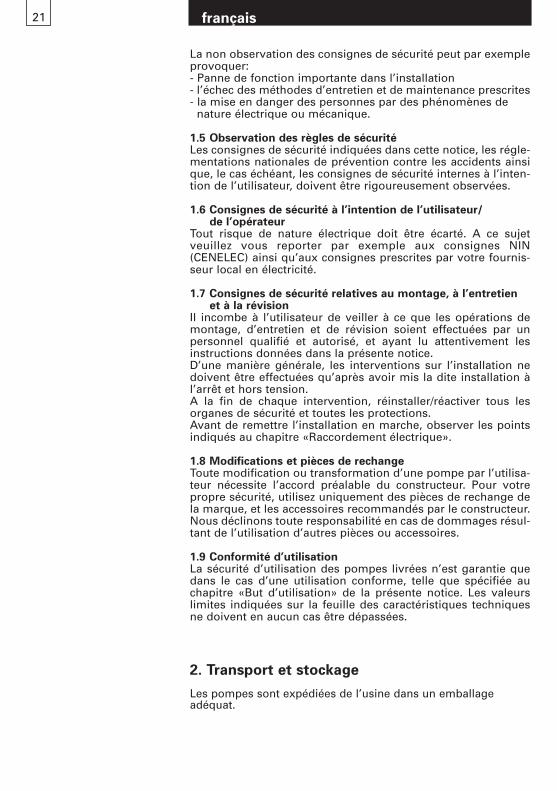
La non observation des consignes de sécurité peut par exempleprovoquer:- Panne de fonction importante dans l’installation - l’échec des méthodes d’entretien et de maintenance prescrites- la mise en danger des personnes par des phénomènes de
nature électrique ou mécanique.
1.5 Observation des règles de sécuritéLes consignes de sécurité indiquées dans cette notice, les régle-mentations nationales de prévention contre les accidents ainsique, le cas échéant, les consignes de sécurité internes à l’inten-tion de l’utilisateur, doivent être rigoureusement observées.
1.6 Consignes de sécurité à l’intention de l’utilisateur/de l’opérateur
Tout risque de nature électrique doit être écarté. A ce sujet veuillez vous reporter par exemple aux consignes NIN (CENELEC) ainsi qu’aux consignes prescrites par votre fournis-seur local en électricité.
1.7 Consignes de sécurité relatives au montage, à l’entretien et à la révision
Il incombe à l’utilisateur de veiller à ce que les opérations demontage, d’entretien et de révision soient effectuées par un personnel qualifié et autorisé, et ayant lu attentivement lesinstructions données dans la présente notice.D’une manière générale, les interventions sur l’installation nedoivent être effectuées qu’après avoir mis la dite installation àl’arrêt et hors tension.A la fin de chaque intervention, réinstaller/réactiver tous lesorganes de sécurité et toutes les protections.Avant de remettre l’installation en marche, observer les pointsindiqués au chapitre «Raccordement électrique».
1.8 Modifications et pièces de rechangeToute modification ou transformation d’une pompe par l’utilisa-teur nécessite l’accord préalable du constructeur. Pour votrepropre sécurité, utilisez uniquement des pièces de rechange dela marque, et les accessoires recommandés par le constructeur. Nous déclinons toute responsabilité en cas de dommages résul-tant de l’utilisation d’autres pièces ou accessoires.
1.9 Conformité d’utilisationLa sécurité d’utilisation des pompes livrées n’est garantie quedans le cas d’une utilisation conforme, telle que spécifiée auchapitre «But d’utilisation» de la présente notice. Les valeurslimites indiquées sur la feuille des caractéristiques techniquesne doivent en aucun cas être dépassées.
français21
2. Transport et stockage
Les pompes sont expédiées de l’usine dans un emballage adéquat.
3.2 Température et pression de serviceTemérature de l’eau admissible: +15 °C à +110 °CPression admissible: max. 10 barTempérature ambiante: max. 40 °C
Utilisation dans installations d’eau potable:Temérature de l’eau admissible: +15 °C à 85 °CDureté de l’eau admissible: max. 35 °fH (=20 °dH)
(Température de l’eau moins 65 °C)max. 25 °fH (=14 °dH) (Température de l’eau moins 85 °C)
Autres indications, voir chapitre 11.
Elles ne doivent transporter aucun liquide combustible ou explosif.Le liquide ne doit pas contenir de matières solides, de fibres ou d'huiles minérales.
français22
4. Montage
4.1 Rinçage de l’installation de chauffage (la pompe démontée)De manière à écarter tout inconvénient désagréable (interruption de fonctionnement ou non redémarrage du circulateur après une longue période de non-utilisation), nous vous conseillons, dans le cas d’un système de chauffage venant juste d’être installéou transformé, de le purger après sa première phase de chauffage,puis de bien le rincer avant de le remplir de nouveau.L’installation de chauffage doit être conforme aux règles de l’art(présence d’un vase d’expansion/d’une canalisation d’expansion).
4.2 Antigel (si nécessaire)Important: Rincez particulièrement bien la tuyauterie avant de remplir le mélange antigel. Suivez les instructions du fournisseurd’antigel en ce qui concerne le mélange et le remplissage de même que le choix des matériaux du réseau de conduites et de l’appareillage (observer la protection contre la corrosion!).Le mélange eau/glycol est admis jusqu'à une part de 50% de glycol.A partir d’une part de 10% de glycol, corriger les données de refoulement de la pompe en conséquence.
4.3 MontageMontage seulement après l’achèvement de tous les travaux de soudageet brasage sur l’installation. Eviter absolument les égouttements d’eausur le moteur de la pompe, spécialement sur l’électronique.
3. But d’utilisation
Les circulateurs Biral de la série
AX 12, AX 13, AXW 12, AXW 13
possèdent un moteur à aimant permanent avec chemise spécialeet un convertisseur de fréquence intégré avec régulation à pression constante, à pression proportionnelle et à vitesse constante.La pompe est utilisée pour le transport de liquides dans des:– installations de chauffage à eau chaude– systèmes industriels fermés à circulation.– Installations d’eau potable (AXW)
3.1 Fluide transportéLe fluide véhiculé dans les installations de chauffage doit répondreaux exigences sur l’eau de chauffage selon VDI 2035.Mélange eau-glycol autorisé jusqu’à une proportion de 50% de glycol.
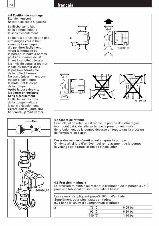
4.4 Position de montageEtat de livraisonRaccord de câble à gauche
La flèche sur le bâti de la pompe indique le sens d’écoulement.
La boîte à bornes ne doit pasêtre dirigée vers le haut,sinon de l’eau risque d’y pénétrer facilement.Avant le montage de la pompe, la boîte à bornespeut être tournée de 90°.Il faut à cet effet dévisser les 4 vis du corps et tournerla tête du moteur dans la position admissible de la boîte à bornes.Ne pas déplacer ni endom-mager le joint entre le moteur et le corps de la pompe.Après la pose des vis, les serrer en croisant.Sens d’écoulementLa flèche sur le corps de la pompe indique le sens d’écoulement.L’arbre doit toujours êtrehorizontal, jamais vertical.
4.5 Clapet de retenueSi un clapet de retenue est monté, la pompe doit être réglée (voir point 5.4.2) de telle sorte que la pression minimale de refoulement de la pompe dépasse en tout temps la pression de fermeture du clapet.
Poser des vannes d’arrêt avant et après la pompe.On évite ainsi lors d'un éventuel remplacement de la pompe la vidange et le remplissage de l'installation.
français23
961082_00
961083_00
961084_00
4.6 Pression minimaleLa pression minimale au raccord d’aspiration de la pompe à 75°Cpour une lubrification sûre des paliers lisses:
Les valeurs s’appliquent jusqu’à 500 m d’altitude.Supplément pour plus hautes altitudes:0,01 bar par 100 m d’augmentation d’altitude
à 75 °C 0,05 bar90 °C 0,30 bar
110 °C 1,10 bar
français24
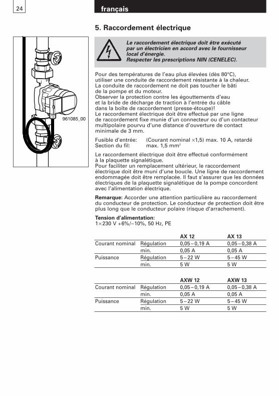
Le raccordement électrique doit être exécuté par un électricien en accord avec le fournisseur local d’énergie.Respecter les prescriptions NIN (CENELEC).
Pour des températures de l’eau plus élevées (dès 80°C), utiliser une conduite de raccordement résistante à la chaleur.La conduite de raccordement ne doit pas toucher le bâti de la pompe et du moteur.Observer la protection contre les égouttements d’eau et la bride de décharge de traction à l’entrée du câble dans la boîte de raccordement (presse-étoupe)!Le raccordement électrique doit être effectué par une ligne de raccordement fixe munie d’un connecteur ou d’un contacteurmultipolaire pourvu d’une distance d’ouverture de contact minimale de 3 mm.
Fusible d’entrée: (Courant nominal ×1,5) max. 10 A, retardéSection du fil: max. 1,5 mm2
Le raccordement électrique doit être effectué conformément à la plaquette signalétique.Pour faciliter un remplacement ultérieur, le raccordement électrique doit être muni d’une boucle. Une ligne de raccordementendommagée doit être remplacée. Il faut s’assurer que les donnéesélectriques de la plaquette signalétique de la pompe concordentavec l’alimentation électrique.
Remarque: Accorder une attention particulière au raccordement du conducteur de protection. Le conducteur de protection doit êtreplus long que le conducteur polaire (risque d'arrachement).
Tension d’alimentation:1× 230 V +6%/–10%, 50 Hz, PE
5. Raccordement électrique
AX 12 AX 13
Courant nominal Régulation 0,05 – 0,19 A 0,05 – 0,38 Amin. 0,05 A 0,05 A
Puissance Régulation 5 – 22 W 5 – 45 Wmin. 5 W 5 W
AXW 12 AXW 13
Courant nominal Régulation 0,05 – 0,19 A 0,05 – 0,38 Amin. 0,05 A 0,05 A
Puissance Régulation 5 – 22 W 5 – 45 Wmin. 5 W 5 W
961085_00
français25
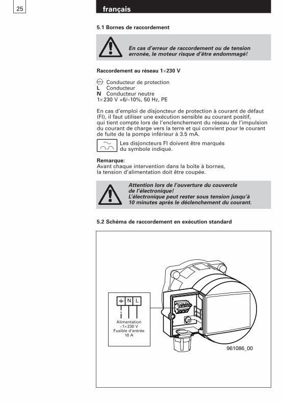
Raccordement au réseau 1×230 V
Conducteur de protectionL ConducteurN Conducteur neutre1× 230 V +6/–10%, 50 Hz, PE
En cas d’emploi de disjoncteur de protection à courant de défaut(FI), il faut utiliser une exécution sensible au courant positif, qui tient compte lors de l’enclenchement du réseau de l’impulsiondu courant de charge vers la terre et qui convient pour le courantde fuite de la pompe inférieur à 3.5 mA.
Les disjoncteurs FI doivent être marqués du symbole indiqué.
Remarque:Avant chaque intervention dans la boîte à bornes, la tension d’alimentation doit être coupée.
5.1 Bornes de raccordement
En cas d’erreur de raccordement ou de tensionerronée, le moteur risque d’être endommagé!
Attention lors de l’ouverture du couvercle de l’électronique! L’électronique peut rester sous tension jusqu’à 10 minutes après le déclenchement du courant.
961086_00
N L
Speisung ~ 1x230V
Vorsicherung10A
Alimentation~1× 230 V
Fusible d’entrée10 A
5.2 Schéma de raccordement en exécution standard
français26
6. Réglages
6.1 Réglage de la régulation et du débit volumique
Pos. Description
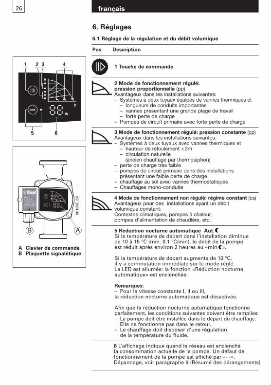
A Clavier de commandeB Plaquette signalétique
9610
87_0
0
B A 5 Réduction nocturne automatique Aut.Si la température de départ dans l’installation diminue de 10 à 15 °C (min. 0.1 °C/min), le débit de la pompe est réduit après environ 2 heures au «min ».
Si la température de départ augmente de 10 °C, il y a commutation immédiate sur le mode réglé.La LED est allumée: la fonction «Réduction nocturne automatique» est enclenchée.
Remarques:– Pour la vitesse constante I, II ou III, la réduction nocturne automatique est désactivée.
Afin que la réduction nocturne automatique fonctionne parfaitement, les conditions suivantes doivent être remplies:– La pompe doit être installée dans le départ du chauffage.
Elle ne fonctionne pas dans le retour.– Le chauffage doit disposer d'une régulation
de la température du fluide.
1 Touche de commande
2 Mode de fonctionnement régulé: pression proportionnelle (pp)Avantageux dans les installations suivantes:– Systèmes à deux tuyaux équipés de vannes thermiques et
– longueurs de conduits importantes– vannes présentant une grande plage de travail– forte perte de charge
– Pompes de circuit primaire avec forte perte de charge
3 Mode de fonctionnement régulé: pression constante (cp)Avantageux dans les installations suivantes:– Systèmes à deux tuyaux avec vannes thermiques et
– hauteur de refoulement <2m– circulation naturelle
(ancien chauffage par thermosiphon)– perte de charge très faible– pompes de circuit primaire dans des installations
présentant une faible perte de charge– chauffage au sol avec vannes thermostatiques – Chauffages mono-conduite
4 Mode de fonctionnement non régulé: régime constant (cs)Avantageux pour des installations ayant un débit volumique constant:Contextes climatiques, pompes à chaleur, pompes d’alimentation de chaudière, etc.
1
5 6
2 3 4
6 L’affichage indique quand le réseau est enclenché la consommation actuelle de la pompe. Un défaut de fonctionnement de la pompe est affiché par «- -».Dépannage, voir paragraphe 9 (Résumé des dérangements)
27 français
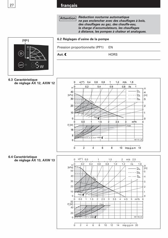
6.2 Réglages d’usine de la pompe
Pression proportionnelle (PP1) EN
Aut. HORS
6.3 Caractéristique de réglage AX 12, AXW 12
6.4 Caractéristique de réglage AX 13, AXW 13
0
0 0
1
H[m]
0
20
0
0
0
10
imp.g.p.m
961158_00
max
min
min
max
20
30
40
50
2
3
4
5
H[kPa]
P [W]
0.5 1 1.5 2 2.5 3 3.5 4 4.5 5 m³/h 6
0.2 0.4 0.6 0.8 1.0 1.2 l/s 1.6
v(1") 0.5 1 1.5 2 2.5
2 4 6 8 10 12 14 20
1
40
60
m/s
H
[m]
max
H
[kPa]
P [W]1
961151_00
min
min
max
Réduction nocturne automatiquene pas enclencher avec des chauffages à bois, des chauffages au gaz, des chauffe-eau, la charge d’accumulateurs, les chauffages à distance, les pompes à chaleur et analogues.
Attention
28 français
7. Mise en service/contrôle de fonctionnement
7.1 Généralités Rincer à fond l’installation sans la pompe. Voir paragraphe 4.Remplir l’installation dans les règles et la purger d’air.Ne mettre la pompe en marche que si l’installation est remplie.Enclencher la tension d’alimentation.
7.2 Purge d’airLa purge d'air, en particulier l’espace du moteur, se fait d’elle-même après une courte durée de fonctionnement. Une brève marche à sec (max. 2 min) n’endommage pas la pompe.Il est recommandé de faire fonctionnement brièvement la pompesur «max.», afin d'assurer une purge d'air rapide du système.
7.3 Contrôle de fonctionnementUne LED doit toujours être allumée et la consommation actuelle de puissance doit être affichée.(Voir paragraphe 6.1 Pos 6)
7.4 DéblocagePas nécessaire. Le moteur démarrage avec un fort couple, voir paragraphe 8.
Il y a un risque de brûlure!
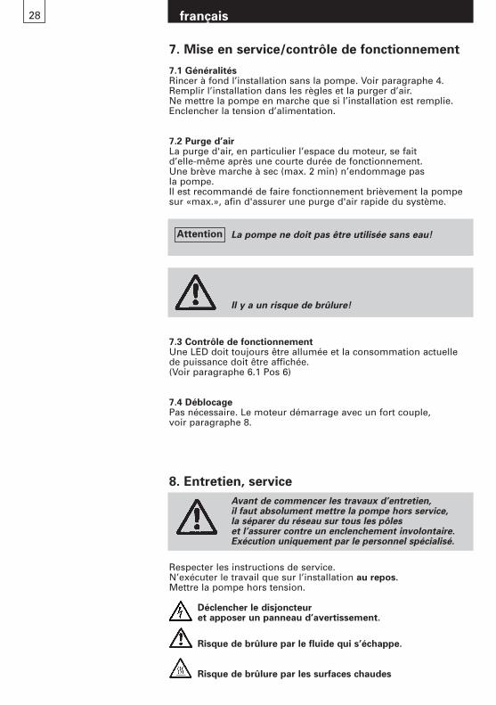
Avant de commencer les travaux d’entretien, il faut absolument mettre la pompe hors service, la séparer du réseau sur tous les pôles et l’assurer contre un enclenchement involontaire.Exécution uniquement par le personnel spécialisé.
Respecter les instructions de service.N’exécuter le travail que sur l’installation au repos.Mettre la pompe hors tension.
Déclencher le disjoncteur et apposer un panneau d’avertissement.
Risque de brûlure par le fluide qui s’échappe.
Risque de brûlure par les surfaces chaudes
8. Entretien, service
La pompe ne doit pas être utilisée sans eau!Attention
29 français
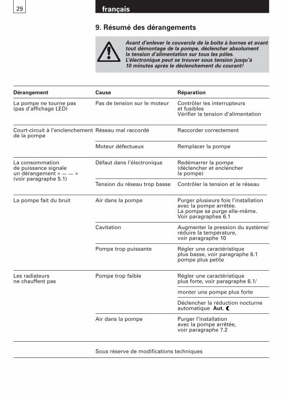
Avant d’enlever le couvercle de la boîte à bornes et avanttout démontage de la pompe, déclencher absolument la tension d’alimentation sur tous les pôles.L’électronique peut se trouver sous tension jusqu’à 10 minutes après le déclenchement du courant!
9. Résumé des dérangements
Dérangement Cause Réparation
La pompe ne tourne pas Pas de tension sur le moteur Contrôler les interrupteurs (pas d’affichage LED) et fusibles
Vérifier la tension d’alimentation
Court-circuit à l’enclenchement Réseau mal raccordé Raccorder correctementde la pompe
Moteur défectueux Remplacer la pompe
La consommation Défaut dans l’électronique Redémarrer la pompe de puissance signale (déclencher et enclencher un dérangement « » la pompe)(voir paragraphe 5.1)
Tension du réseau trop basse Contrôler la tension et le réseau
La pompe fait du bruit Air dans la pompe Purger plusieurs fois l’installation avec la pompe arrêtée.La pompe se purge elle-même.Voir paragraphes 6.1
Cavitation Augmenter la pression du système/ réduire la température, voir paragraphe 10
Pompe trop puissante Régler une caractéristique plus basse, voir paragraphe 6.1pompe plus petite
Les radiateurs Pompe trop faible Régler une caractéristique ne chauffent pas plus forte, voir paragraphe 6.1/
monter une pompe plus forte
Déclencher la réduction nocturne automatique Aut.
Air dans la pompe Purger l’installation avec la pompe arrêtée,voir paragraphe 7.2
Sous réserve de modifications techniques
30 français
10. Accessoires
AX
12
AX
12-1
AX
12-2
AX
12-3
AX
12-4
AX
13
AX
13-1
AX
13-2
AX
13-3
AX
13-4
AX
W 1
2
AX
W 1
2-1
AX
W 1
3
AX
W 1
3-1
Pour de plus amplesinfor-mations, voir chapitre
Coquilles d’isolation thermique 3 3 3 – – 3 3 3 – – – l – l 10.1
Kit d’isolement – – – – – – – – – – 3 – 3 – 10.2
3 ard (contenu dans la livraison)
l Disponible (en option)
– non disponible
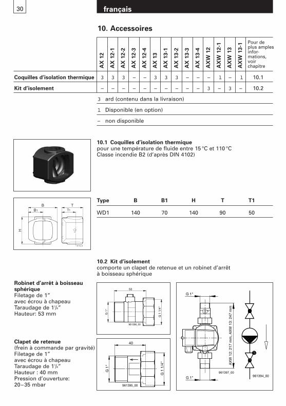
Robinet d’arrêt à boisseausphérique Filetage de 1” avec écrou à chapeauTaraudage de 11/4” Hauteur: 53 mm
Clapet de retenue (frein à commande par gravité)Filetage de 1” avec écrou à chapeauTaraudage de 11/4” Hauteur : 40 mmPression d’ouverture: 20–35 mbar
961194_00
BB1 T1
T
H
10.1 Coquilles d’isolation thermiquepour une température de fluide entre 15 °C et 110 °CClasse incendie B2 (d’après DIN 4102)
Type B B1 H T T1
WD1 140 70 140 90 50
10.2 Kit d’isolementcomporte un clapet de retenue et un robinet d’arrêt à boisseau sphérique
G 1
"
G 1
1/4
"
40
961395_00
G 1"
G 1"961397_00
AX
W 1
2: 2
17 m
m, A
XW
13:
247
mm
G 1
"
G 1
1/4
"
53
961396_00
961394_00
31 français
11. Caractéristiques techniques
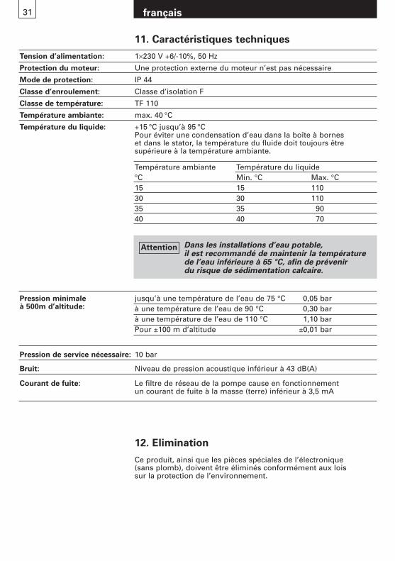
Tension d’alimentation: 1×230 V +6/-10%, 50 Hz
Protection du moteur: Une protection externe du moteur n’est pas nécessaire
Mode de protection: IP 44
Classe d’enroulement: Classe d’isolation F
Classe de température: TF 110
Température ambiante: max. 40 °C
Température du liquide: +15 °C jusqu’à 95 °CPour éviter une condensation d’eau dans la boîte à bornes et dans le stator, la température du fluide doit toujours être supérieure à la température ambiante.
jusqu’à une température de l’eau de 75 °C 0,05 barà une température de l’eau de 90 °C 0,30 barà une température de l’eau de 110 °C 1,10 barPour ±100 m d’altitude ±0,01 bar
Pression de service nécessaire: 10 bar
Bruit: Niveau de pression acoustique inférieur à 43 dB(A)
Courant de fuite: Le filtre de réseau de la pompe cause en fonctionnement un courant de fuite à la masse (terre) inférieur à 3,5 mA
Pression minimaleà 500m d’altitude:
Température ambiante Température du liquide°C Min. °C Max. °C15 15 11030 30 11035 35 9040 40 70
12. Elimination
Ce produit, ainsi que les pièces spéciales de l’électronique (sans plomb), doivent être éliminés conformément aux lois sur la protection de l’environnement.
Dans les installations d’eau potable, il est recommandé de maintenir la température de l’eau inférieure à 65 °C, afin de prévenir du risque de sédimentation calcaire.
Attention

italiano33
Indice
1. Avvertenze di sicurezza Pagina 341.1 Generalità 341.2 Contrassegno delle avvertenze 341.3 Qualifica e addestramento del personale 341.4 Pericoli in caso di inosservanza
della avvertenze di sicurezza 341.5 Lavoro in conformità alle avvertenze
e norme di sicurezza 351.6 Avvertenze di sicurezza per l’esercente e l’operatore 351.7 Avvertenze di sicurezza per i lavori di montaggio,
manutenzione e ispezione 351.8 Modifiche e fabbricazione di parti
di ricambio senza autorizzazione 351.9 Modalità d’uso non consentite 35
2. Trasporto e magazzinaggio 35
3. Caratteristiche, campo d’applicazione 363.1 Liquido convogliato 363.2 Temperatura di esercizio/Pressione di esercizio 36
4. Montaggio 374.1 Lavaggio dell’impianto di riscaldamento 374.2 Antigelo 374.3 Installazione 374.4 Posizione di montaggio 384.5 Valvola di non ritorno 384.6 Pressione minima 38
5. Allacciamento elettrico 395.1 Morsetti 395.2 Schema di collegamento della versione standard 39
6. Impostazioni 406.1 Impostazione della regolazione e dell'altezza manometrica 406.2 Impostazione di fabbrica della pompa 416.3 Linea caratteristica di regolazione AX 12, AXW 12 416.4 Linea caratteristica di regolazione AX 13, AXW 13 41
7. Messa in funzione/Controllo del funzionamento 427.1 Generalità 427.2 Sfiato 427.3 Controllo del funzionamento 427.4 Sbloccaggio 42
8. Manutenzione, assistenza 42
9. Panoramica delle anomalie 43
10. Accessori 4410.1 Rivestimenti isolanti 4410.2 Set intercettazione 44
11. Dati tecnici 45
12. Smaltimento 45
italiano34
1. Avvertenze di sicurezza
1.1 GeneralitàQueste istruzioni per il montaggio e l’uso contengono delleavvertenze fondamentali di cui va tenuto conto ai fini dell’installazione, dell’uso e della manutenzione. Esse debbonoquindi essere assolutamente lette dal montatore e dal personalespecializzato, nonché dall’esercente responsabile, prima delmontaggio e della messa in funzione. Dovranno inoltre restaresempre a disposizione nelle vicinanze dell’impianto.Non solo dovranno essere rispettate le avvertenze di sicurezzagenerali, riportate in questo capitolo e intitolate «Avvertenze disicurezza», ma anche le avvertenze di sicurezza particolari riportate negli altri capitoli.
1.2 Contrassegno delle avvertenze
Le avvertenze applicate direttamente sull’impianto, come adesempio:
- freccia per il senso di rotazione- contrassegno per raccordi fluidi
debbono essere assolutamente rispettate e mantenute in statoperfettamente leggibile.
1.3 Qualifica e addestramento del personaleIl personale responsabile per il montaggio, il comando, lamanutenzione e l’ispezione deve dimostrare di possedere laqualifica adatta per svolgere questi lavori. L’ambito di respon-sabilità, le competenze e i compiti di sorveglianza da parte delpersonale debbono essere stabiliti chiaramente da parte dell’esercente.
1.4 Pericoli in caso di inosservanza delle avvertenze di sicurezza
L’inosservanza delle avvertenze di sicurezza può causare pericolo alle persone, all’ambiente e all’impianto. L’inosservanzadelle avvertenze di sicurezza può condurre alla perdita di tutti i diritti al risarcimento di eventuali danni.
Questo simbolo avverte dalla presenza di tensioneelettrica pericolosa.«Simbolo di sicurezza secondo DIN 4844-W8»
Le avvertenze di sicurezza contenute in queste istruzioni per il montaggio e l’uso, tali da comportare pericolo per la persona in caso di inosservanza, sono contrassegnate espressa-mente con il simbolo di pericolo generale «Simbolo di sicurezza secondo DIN 4844-W9».
Questo simbolo si trova nelle avvertenze di sicurezza la cui inosservanza può comportare dei pericoli per la macchina e le sue funzioni.
Attenzione
italiano35
In particolare l’inosservanza può provocare, ad esempio, i seguenti pericoli:- guasti tali da pregiudicare funzioni importanti per l’impianto- non funzionamento di metodi prescritti per la manutenzione- esposizione a pericolo di persone a causa di azioni elettriche
e meccaniche
1.5 Lavoro in conformità alle avvertenze e norme di sicurezzaDebbono essere osservate: le avvertenze di sicurezza riportatein queste istruzioni per il montaggio e l’uso, le norme nazionaliesistenti riguardo la prevenzione degli infortuni, eventualinorme interne sul lavoro, l’uso e la sicurezza stabilite dall’esercente.
1.6 Avvertenze di sicurezza per l’esercente e l’operatoreDeve essere prevenuto qualsiasi pericolo causato da energiaelettrica (per maggiori particolari vedi ad esempio le normedella NIN (CENELEC) e delle aziende elettriche locali).
1.7 Avvertenze di sicurezza per i lavori di montaggio, manutenzione e ispezione.
L’esercente dovrà provvedere a far eseguire tutti i lavori di montaggio, manutenzione e ispezione da personale autorizzatoe qualificato; tale personale dovrà informarsi adeguatamentetramite approfondita lettura delle istruzioni di montaggio e diuso.Fondamentalmente, i lavori sull’impianto dovranno essere compiuti solo in stato di macchina ferma e non sotto tensione.Immediatamente dopo la conclusione dei lavori, si dovrannonuovamente applicare o mettere in funzione tutte le attrezzaturedi sicurezza e di protezione.Prima della rimessa in funzione si dovrà tener conto dei puntielencati nel capitolo «Allacciamento elettrico».
1.8 Modifiche e fabbricazione di parti di ricambio senza autorizzazione
Qualsiasi cambiamento o modifica delle pompe è consentitosolo previa autorizzazione da parte del fabbricante. Le parti diricambio originali e gli accessori autorizzati dal fabbricante sonoimportanti ai fini della sicurezza.L’uso di parti estranee può condurre all’annullamento di ogniresponsabilità per le conseguenze derivanti.
1.9 Modalità d’uso non consentiteLa sicurezza di funzionamento delle pompe fornite è garantitasolo a condizione che esse vengano usate in conformità alle intenzioni del costruttore, come da capitolo «Campo d’applicazione» delle istruzioni di montaggio ed uso. I valorilimite indicati nei dati tecnici non debbono essere in alcun casosuperati.
2. Trasporto/Magazzinaggio
Le pompe lasciano lo stabilimento del costruttore inserite in un apposito imballaggio.
italiano36
4. Montaggio
4.1 Lavaggio dell’impianto di riscaldamento (con pompa smontata)Se l’impianto è stato installato o rifatto da poco, consigliamo di svuotarlo dopo il primo riscaldamento, poi di pulirlo a fondo e infine di riempirlo di nuovo. Questo è necessario per evitare fastidiose interruzioni dell’esercizio e il mancato avviamento dellapompa dopo lunghi periodi di inattività.L’impianto deve corrispondere ai requisiti più moderni della tecnica(presenza di un vaso di espansione/di una tubazione di sicurezza).
4.2 Antigelo (se necessario)Importante: risciacquare in maniera approfondita ed accurata la rete delle tubazioni, prima di immettere la miscela di antigelo.Attenersi alle istruzioni del fornitore del prodotto antigelo per quanto concerne la miscela, l’inserimento e la scelta dei materiali nella rete di tubazioni e apparecchi (osservare la protezione contro la corrosione!). Sono ammesse le miscele di acqua/glicole fino al 50% di glicole. A partire dal 10% di glicole,correggere di conseguenza i dati di portata delle pompe.
4.3 InstallazioneEseguire l’installazione solo dopo aver portato a termine tutti i lavori di saldatura sull’impianto.Evitare assolutamente lo stillicidio sul motore della pompa, e proteggere soprattutto i componenti elettronici.Installare il corpo della pompa nell’impianto senza tensione.
3.2 Temperatura d’esercizio/Pressione d’esercizioTemperatura dell’acqua ammessa: da +15 °C a +110 °CPressione d’esercizio ammessa: max. 10 barTemperatura ambiente: max. 40 °C
Per l’uso nei impianti d’acqua potabile:Temperatura dell’acqua ammessa: +15 °C a 85 °CDurezza dell’acqua ammessa: max. 35 °fH (=20 °dH)
Temperatura dell’acqua meno 65 °C)max. 25 °fH (=14 °dH) Temperatura dell’acqua meno 85 °C)
Per altri dati, vedere il capitolo 11.
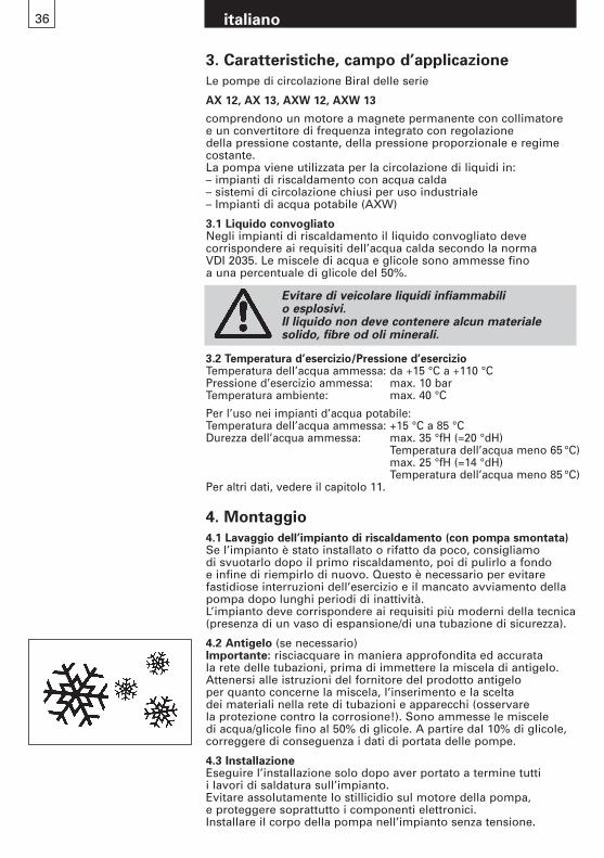
Evitare di veicolare liquidi infiammabili o esplosivi.Il liquido non deve contenere alcun materiale solido, fibre od oli minerali.
3. Caratteristiche, campo d’applicazione
Le pompe di circolazione Biral delle serie
AX 12, AX 13, AXW 12, AXW 13
comprendono un motore a magnete permanente con collimatore e un convertitore di frequenza integrato con regolazione della pressione costante, della pressione proporzionale e regimecostante.La pompa viene utilizzata per la circolazione di liquidi in:– impianti di riscaldamento con acqua calda– sistemi di circolazione chiusi per uso industriale– Impianti di acqua potabile (AXW)
3.1 Liquido convogliatoNegli impianti di riscaldamento il liquido convogliato deve corrispondere ai requisiti dell’acqua calda secondo la norma VDI 2035. Le miscele di acqua e glicole sono ammesse fino a una percentuale di glicole del 50%.
italiano37
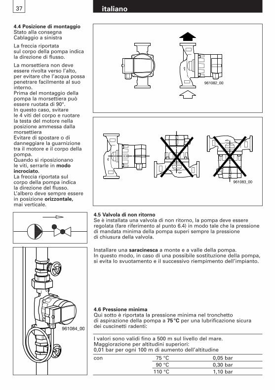
4.5 Valvola di non ritornoSe è installata una valvola di non ritorno, la pompa deve essereregolata (fare riferimento al punto 6.4) in modo tale che la pressionedi mandata minima della pompa superi sempre la pressione di chiusura della valvola.
Installare una saracinesca a monte e a valle della pompa.In questo modo, in caso di una possibile sostituzione della pompa,si evita lo svuotamento e il successivo riempimento dell’impianto.
961082_00
961083_00
961084_00
4.4 Posizione di montaggioStato alla consegnaCablaggio a sinistra
La freccia riportata sul corpo della pompa indicala direzione di flusso.
La morsettiera non deveessere rivolta verso l’alto, per evitare che l’acqua possapenetrare facilmente al suointerno.Prima del montaggio dellapompa la morsettiera puòessere ruotata di 90°.In questo caso, svitare le 4 viti del corpo e ruotare la testa del motore nella posizione ammessa dallamorsettieraEvitare di spostare o di danneggiare la guarnizionetra il motore e il corpo dellapompa.Quando si riposizionano le viti, serrarle in modo incrociato.La freccia riportata sul corpo della pompa indica la direzione del flusso.L’albero deve sempre esserein posizione orizzontale, mai verticale.
4.6 Pressione minimaQui sotto è riportata la pressione minima nel tronchetto di aspirazione della pompa a 75°C per una lubrificazione sicura dei cuscinetti radenti:
I valori sono validi fino a 500 m sul livello del mare.Maggiorazione per altitudini superiori:0,01 bar per ogni 100 m di aumento dell’altitudine
con 75 °C 0,05 bar90 °C 0,30 bar
110 °C 1,10 bar
italiano38
961085_00
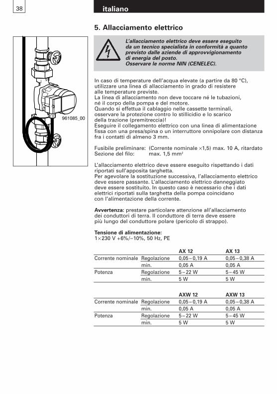
L’allacciamento elettrico deve essere eseguito da un tecnico specialista in conformità a quanto previsto dalle aziende di approvvigionamento di energia del posto.Osservare le norme NIN (CENELEC).
In caso di temperature dell’acqua elevate (a partire da 80 °C), utilizzare una linea di allacciamento in grado di resistere alle temperature previste.La linea di allacciamento non deve toccare né le tubazioni, né il corpo della pompa e del motore.Quando si effettua il cablaggio nelle cassette terminali, osservare la protezione contro lo stillicidio e lo scarico della trazione (premitreccia)!Eseguire il collegamento elettrico con una linea di alimentazionefissa con una presa/spina o un interruttore onnipolare con distanzafra i contatti di almeno 3 mm.
Fusibile preliminare: (Corrente nominale ×1,5) max. 10 A, ritardatoSezione del filo: max. 1,5 mm2
L’allacciamento elettrico deve essere eseguito rispettando i datiriportati sull’apposita targhetta.Per agevolare la sostituzione successiva, l’allacciamento elettricodeve essere passante. L’allacciamento elettrico danneggiato deve essere sostituito. In questo caso è necessario che i dati elettrici riportati sulla targhetta della pompa coincidano con l’alimentazione della corrente.
Avvertenza: prestare particolare attenzione all’allacciamento dei conduttori di terra. Il conduttore di terra deve essere più lungo del conduttore polare (pericolo di strappo).
Tensione di alimentazione:1× 230 V +6%/–10%, 50 Hz, PE
5. Allacciamento elettrico
AX 12 AX 13
Corrente nominale Regolazione 0,05 – 0,19 A 0,05 – 0,38 Amin. 0,05 A 0,05 A
Potenza Regolazione 5 – 22 W 5 – 45 Wmin. 5 W 5 W
AXW 12 AXW 13
Corrente nominale Regolazione 0,05 – 0,19 A 0,05 – 0,38 Amin. 0,05 A 0,05 A
Potenza Regolazione 5 – 22 W 5 – 45 Wmin. 5 W 5 W
italiano39
961086_00
N L
Speisung ~ 1x230V
Vorsicherung10A
Alimentazione~1× 230 VPrefusible
10 A
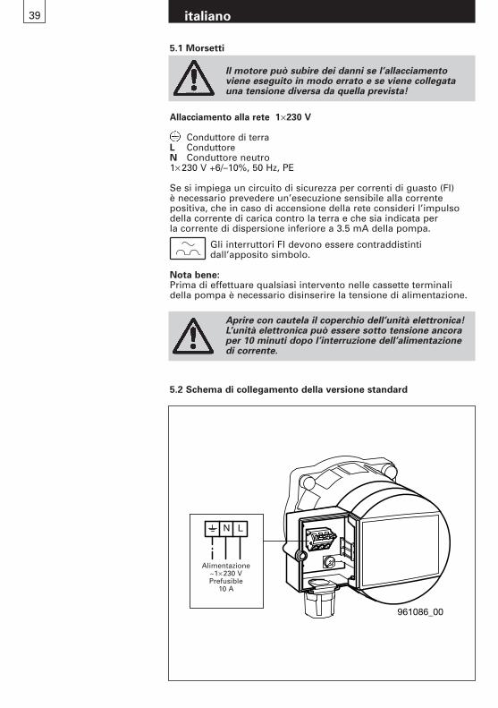
5.2 Schema di collegamento della versione standard
Allacciamento alla rete 1×230 V
Conduttore di terraL ConduttoreN Conduttore neutro1× 230 V +6/–10%, 50 Hz, PE
Se si impiega un circuito di sicurezza per correnti di guasto (FI) è necessario prevedere un’esecuzione sensibile alla corrente positiva, che in caso di accensione della rete consideri l’impulsodella corrente di carica contro la terra e che sia indicata per la corrente di dispersione inferiore a 3.5 mA della pompa.
Gli interruttori FI devono essere contraddistinti dall’apposito simbolo.
Nota bene:Prima di effettuare qualsiasi intervento nelle cassette terminalidella pompa è necessario disinserire la tensione di alimentazione.
5.1 Morsetti
Il motore può subire dei danni se l’allacciamentoviene eseguito in modo errato e se viene collegatauna tensione diversa da quella prevista!
Aprire con cautela il coperchio dell’unità elettronica!L’unità elettronica può essere sotto tensione ancora per 10 minuti dopo l’interruzione dell’alimentazione di corrente.
italiano40
6. Impostazioni
6.1 Impostazione della regolazione e dell’altezza manometrica
Pos. Descrizione
A Tastiera di comandoB Targa aziendale
9610
87_0
0
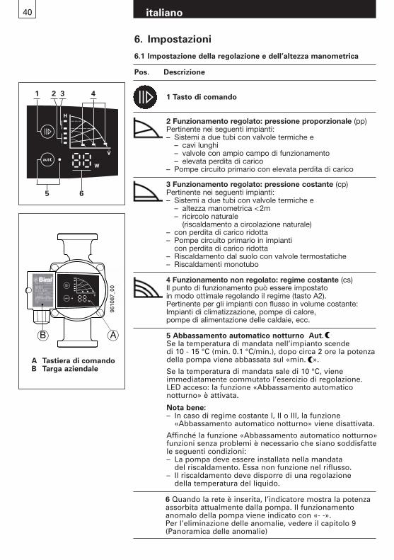
B A 5 Abbassamento automatico notturno Aut.Se la temperatura di mandata nell’impianto scende di 10 - 15 °C (min. 0.1 °C/min.), dopo circa 2 ore la potenza della pompa viene abbassata sul «min. ».
Se la temperatura di mandata sale di 10 °C, viene immediatamente commutato l’esercizio di regolazione.LED acceso: la funzione «Abbassamento automatico notturno» è attivata.
Nota bene:– In caso di regime costante I, II o III, la funzione
«Abbassamento automatico notturno» viene disattivata.
Affinché la funzione «Abbassamento automatico notturno» funzioni senza problemi è necessario che siano soddisfatte le seguenti condizioni:– La pompa deve essere installata nella mandata
del riscaldamento. Essa non funzione nel riflusso.– Il riscaldamento deve disporre di una regolazione
della temperatura del liquido.
1 Tasto di comando
2 Funzionamento regolato: pressione proporzionale (pp)Pertinente nei seguenti impianti:– Sistemi a due tubi con valvole termiche e
– cavi lunghi– valvole con ampio campo di funzionamento– elevata perdita di carico
– Pompe circuito primario con elevata perdita di carico
3 Funzionamento regolato: pressione costante (cp)Pertinente nei seguenti impianti:– Sistemi a due tubi con valvole termiche e
– altezza manometrica <2m– ricircolo naturale
(riscaldamento a circolazione naturale)– con perdita di carico ridotta– Pompe circuito primario in impianti
con perdita di carico ridotta– Riscaldamento dal suolo con valvole termostatiche – Riscaldamenti monotubo
4 Funzionamento non regolato: regime costante (cs)Il punto di funzionamento può essere impostato in modo ottimale regolando il regime (tasto A2).Pertinente per gli impianti con flusso in volume costante:Impianti di climatizzazione, pompe di calore, pompe di alimentazione delle caldaie, ecc.
1
5 6
2 3 4
6 Quando la rete è inserita, l’indicatore mostra la potenza assorbita attualmente dalla pompa. Il funzionamento anomalo della pompa viene indicato con «- -».Per l’eliminazione delle anomalie, vedere il capitolo 9 (Panoramica delle anomalie)
italiano41
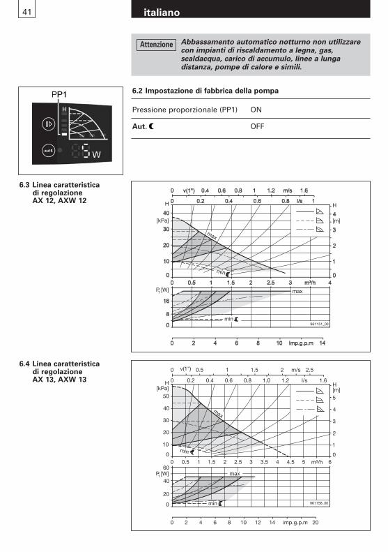
6.3 Linea caratteristica di regolazione AX 12, AXW 12
6.4 Linea caratteristica di regolazione AX 13, AXW 13
0
0 0
1
H[m]
0
20
0
0
0
10
imp.g.p.m
961158_00
max
min
min
max
20
30
40
50
2
3
4
5
H[kPa]
P [W]
0.5 1 1.5 2 2.5 3 3.5 4 4.5 5 m³/h 6
0.2 0.4 0.6 0.8 1.0 1.2 l/s 1.6
v(1") 0.5 1 1.5 2 2.5
2 4 6 8 10 12 14 20
1
40
60
m/s
H
[m]
max
H
[kPa]
P [W]1
961151_00
min
min
max
6.2 Impostazione di fabbrica della pompa
Pressione proporzionale (PP1) ON
Aut. OFF
Abbassamento automatico notturno non utilizzare con impianti di riscaldamento a legna, gas, scaldacqua, carico di accumulo, linee a lunga distanza, pompe di calore e simili.
Attenzione
42 italiano
7. Messa in funzione/Controllo del funzionamento
7.1 GeneralitàPulire accuratamente l’impianto senza la pompa. Vedi il paragrafo 4.Riempire e sfiatare correttamente l’impianto.Mettere in funzione la pompa solo quando l’impianto è stato riempito.Inserire la tensione di alimentazione.
7.2 SfiatoLo sfiato della pompa, in particolare del vano motore, avvieneautonomamente dopo una breve durata del funzionamento. Un breve (max. 2 min.) funzionamento a secco non danneggia la pompa.Si raccomanda di far funzionare brevemente la pompa su «max»,per garantire uno sfiato rapido del sistema.
7.3 Controllo del funzionamentoDeve sempre essere acceso un LED e deve essere visualizzata la potenza assorbita attuale.(vedere il paragrafo 6.1 Pos. 6)
7.4 SbloccaggioNon necessario. Il motore parte con una coppia di avviamento elevata, vedi paragrafo 8.
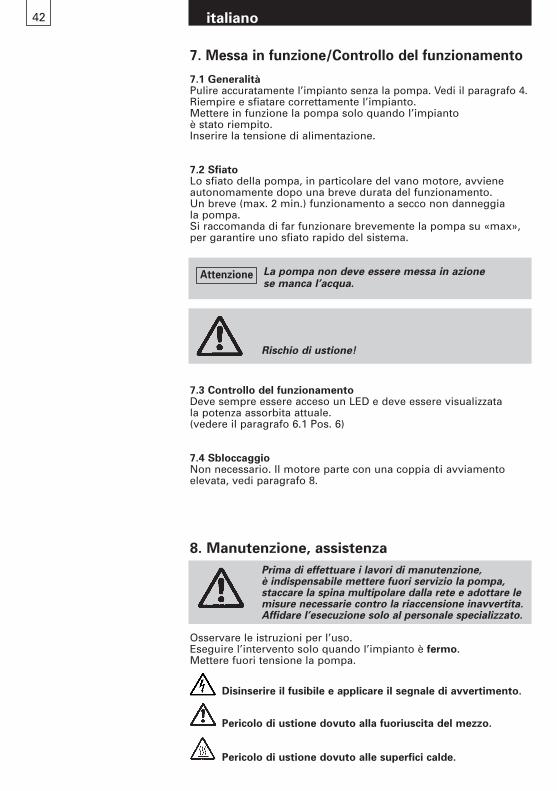
Rischio di ustione!
Prima di effettuare i lavori di manutenzione, è indispensabile mettere fuori servizio la pompa, staccare la spina multipolare dalla rete e adottare lemisure necessarie contro la riaccensione inavvertita.Affidare l’esecuzione solo al personale specializzato.
Osservare le istruzioni per l’uso.Eseguire l’intervento solo quando l’impianto è fermo.Mettere fuori tensione la pompa.
Disinserire il fusibile e applicare il segnale di avvertimento.
Pericolo di ustione dovuto alla fuoriuscita del mezzo.
Pericolo di ustione dovuto alle superfici calde.
8. Manutenzione, assistenza
La pompa non deve essere messa in azione se manca l’acqua.
Attenzione
43 italiano
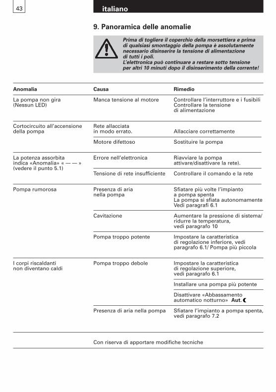
Prima di togliere il coperchio della morsettiera e prima di qualsiasi smontaggio della pompa è assolutamentenecessario disinserire la tensione di alimentazione di tutti i poli.L’elettronica può continuare a restare sotto tensione per altri 10 minuti dopo il disinserimento della corrente!
9. Panoramica delle anomalie
Anomalia Causa Rimedio
La pompa non gira Manca tensione al motore Controllare l’interruttore e i fusibili(Nessun LED) Controllare la tensione
di alimentazione
Cortocircuito all’accensione Rete allacciata della pompa in modo errato. Allacciare correttamente
Motore difettoso Sostituire la pompa
La potenza assorbita Errore nell’elettronica Riavviare la pompaindica «Anomalia» « » attivare/disattivare la rete). (vedere il punto 5.1)
Tensione di rete insufficiente Controllare il comando e la rete
Pompa rumorosa Presenza di aria Sfiatare più volte l’impianto nella pompa a pompa spenta
La pompa si sfiata autonomamenteVedi paragrafi 6.1
Cavitazione Aumentare la pressione di sistema/ridurre la temperatura, vedi paragrafo 10
Pompa troppo potente Impostare la caratteristica di regolazione inferiore, vedi paragrafo 6.1/ Pompa più piccola
I corpi riscaldanti Pompa troppo debole Impostare la caratteristica non diventano caldi di regolazione superiore,
vedi paragrafo 6.1
Installare una pompa più potente
Disattivare «Abbassamento automatico notturno» Aut.
Presenza di aria nella pompa Sfiatare l’impianto a pompa spenta, vedi paragrafo 7.2
Con riserva di apportare modifiche tecniche
44 italiano
10. Accessori
AX
12
AX
12-1
AX
12-2
AX
12-3
AX
12-4
AX
13
AX
13-1
AX
13-2
AX
13-3
AX
13-4
AX
W 1
2
AX
W 1
2-1
AX
W 1
3
AX
W 1
3-1 Per ulte-
riori infor-mazioni,consultareil capitolo
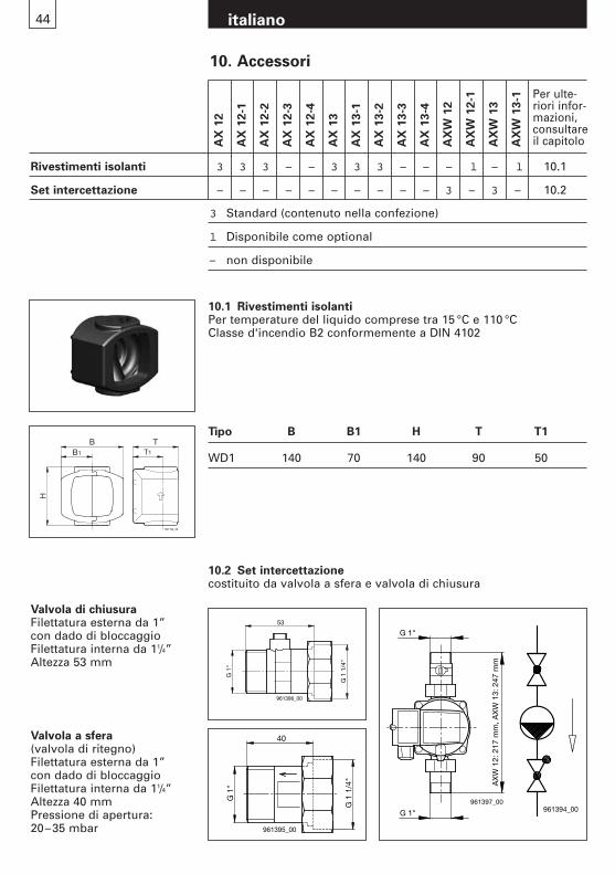
Rivestimenti isolanti 3 3 3 – – 3 3 3 – – – l – l 10.1
Set intercettazione – – – – – – – – – – 3 – 3 – 10.2
3 Standard (contenuto nella confezione)
l Disponibile come optional
– non disponibile
Valvola di chiusuraFilettatura esterna da 1”con dado di bloccaggioFilettatura interna da 11/4”Altezza 53 mm
Valvola a sfera (valvola di ritegno)Filettatura esterna da 1”con dado di bloccaggioFilettatura interna da 11/4”Altezza 40 mmPressione di apertura: 20–35 mbar
961194_00
BB1 T1
T
H
10.1 Rivestimenti isolantiPer temperature del liquido comprese tra 15 °C e 110 °CClasse d'incendio B2 conformemente a DIN 4102
Tipo B B1 H T T1
WD1 140 70 140 90 50
10.2 Set intercettazionecostituito da valvola a sfera e valvola di chiusura
G 1
"
G 1
1/4
"
40
961395_00
G 1"
G 1"961397_00
AX
W 1
2: 2
17 m
m, A
XW
13:
247
mm
G 1
"
G 1
1/4
"
53
961396_00
961394_00
45 italiano
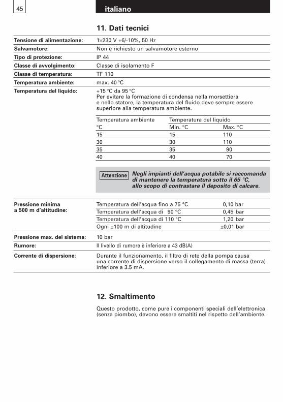
11. Dati tecnici
Tensione di alimentazione: 1×230 V +6/-10%, 50 Hz
Salvamotore: Non è richiesto un salvamotore esterno
Tipo di protezione: IP 44
Classe di avvolgimento: Classe di isolamento F
Classe di temperatura: TF 110
Temperatura ambiente: max. 40 °C
Temperatura del liquido: +15 °C da 95 °CPer evitare la formazione di condensa nella morsettiera e nello statore, la temperatura del fluido deve sempre essere superiore alla temperatura ambiente.
Temperatura dell’acqua fino a 75 °C 0,10 barTemperatura dell’acqua di 90 °C 0,45 barTemperatura dell’acqua di 110 °C 1,20 barOgni ±100 m di altitudine ±0,01 bar
Pressione max. del sistema: 10 bar
Rumore: Il livello di rumore è inferiore a 43 dB(A)
Corrente di dispersione: Durante il funzionamento, il filtro di rete della pompa causa una corrente di dispersione verso il collegamento di massa (terra) inferiore a 3.5 mA.
Pressione minima a 500 m d’altitudine:
Temperatura ambiente Temperatura del liquido°C Min. °C Max. °C15 15 11030 30 11035 35 9040 40 70
12. Smaltimento
Questo prodotto, come pure i componenti speciali dell’elettronica(senza piombo), devono essere smaltiti nel rispetto dell’ambiente.
Negli impianti dell’acqua potabile si raccomandadi mantenere la temperatura sotto il 65 °C,allo scopo di contrastare il deposito di calcare.
Attenzione

47 english
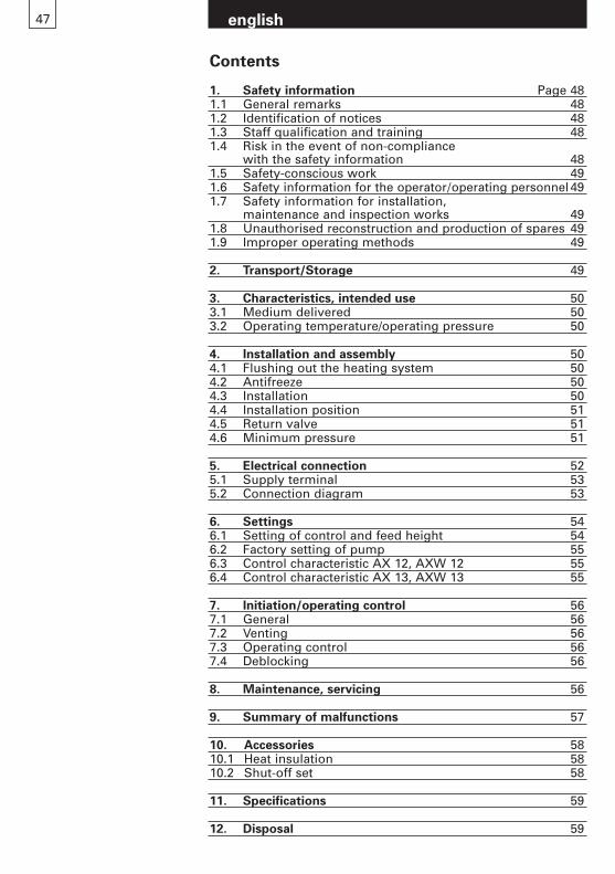
Contents
1. Safety information Page 481.1 General remarks 481.2 Identification of notices 481.3 Staff qualification and training 481.4 Risk in the event of non-compliance
with the safety information 481.5 Safety-conscious work 491.6 Safety information for the operator/operating personnel491.7 Safety information for installation,
maintenance and inspection works 491.8 Unauthorised reconstruction and production of spares 491.9 Improper operating methods 49
2. Transport/Storage 49
3. Characteristics, intended use 503.1 Medium delivered 503.2 Operating temperature/operating pressure 50
4. Installation and assembly 504.1 Flushing out the heating system 504.2 Antifreeze 504.3 Installation 504.4 Installation position 514.5 Return valve 514.6 Minimum pressure 51
5. Electrical connection 525.1 Supply terminal 535.2 Connection diagram 53
6. Settings 546.1 Setting of control and feed height 546.2 Factory setting of pump 556.3 Control characteristic AX 12, AXW 12 556.4 Control characteristic AX 13, AXW 13 55
7. Initiation/operating control 567.1 General 567.2 Venting 567.3 Operating control 567.4 Deblocking 56
8. Maintenance, servicing 56
9. Summary of malfunctions 57
10. Accessories 5810.1 Heat insulation 5810.2 Shut-off set 58
11. Specifications 59
12. Disposal 59
1. Safety information
1.1 General remarksThese installation and operating instructions contain items ofinformation of fundamental importance which must be takeninto account during assembly, operation and maintenance.They should therefore be read without fail before installationand commissioning by the fitter and also the responsible specialist staff/operator. They must always be available for consultation at the plant’s place of deployment.Not only are the general safety hints included in this «SafetyHints» section to be observed, but also the special items ofsafety information included in the other sections.
1.2 Identification of notices
Information signs mounted directly on the plant, such as, forexample
- rotating direction arrow- symbols for fluid connections
must be obeyed without fail and be kept in a fully legible state.
1.3 Staff qualification and trainingThe staff deployed for assembly, operating, maintenance andinspection tasks must show that they have the appropriate qua-lifications for such work. The field of responsibility, competenceand supervision of the staff must be stipulated exactly by theoperator.
1.4 Risks in the event of non-compliance with the safety information
Non-compliance with the safety information can result in bothdanger for persons and also for the plant and the environment.Non-compliance with the safety information can lead to the lossof claims for damages of any kind.
This symbol is a warning of dangerous electricvoltage.«Safety sign according to DIN 4844-W8».
The safety information contained in these installation and operating instructions, non-compliance with which can lead to danger for people, are specially marked with the general danger symbol«Safety sign according to DIN 4844-W9».
You will find this symbol in the case of safetyinformation non-compliance with which can endanger the machine and its functions.
Warning
english48
english49
In detail, non-compliance, for example, may result in the following risks:- failure of important functions in the plant- failure of prescribed methods for servicing and maintenance- danger to persons through electrical and mechanical causes
1.5 Safety-conscious workThe safety information contained in these installation and operating instructions, the existing national regulations for theprevention of accidents, as well as any internal working, operating and safety regulations stipulated by the operatormust be observed.
1.6 Safety information for the operator/operating personnelAny risks from electric power must be eliminated (For detailssee, for example, the regulations published by NIN (CENELEC)and the I.E.E.).
1.7 Safety information for installation, maintenance and inspection works
The operator has to ensure that all installation, maintenanceand inspection works are carried out by authorised and qualifiedspecialist personnel who have informed themselves adequatelyabout the requirements by a thorough study of the installationand operating instructions.Basically, any works on the plant should only be carried outwhen it is at a standstill and not carrying any electrical current.Directly after completion of the works, all safety and protectiveinstallations must be mounted or activated again.Before re-commissioning, the points listed in the section«Electrical connection» must be observed.
1.8 Unauthorised reconstruction and production of sparesReconstruction of or changes to pumps are only permissibleafter consultation with the manufacturer. Genuine spare partsand accessories authorised by the manufacturer serve the causeof safety.The use of other parts can cancel any liability for the resultantconsequences of this.
1.9 Improper operating methodsThe operating reliability of the pumps supplied is only guaranteed with appropriate application of the section«Intended application» of the Installation and OperatingInstructions. The limit values given in the technical data mustnot be exceeded on any account.
2. Transport/storage
The pumps are delivered ex works in suitable packaging.
50 english
4. Installation and assembly
4.1 Flushing out the heating system (with pump removed)In order to avoid undesirable interruptions in operation and non-starting of the pump after long periods of standstill, it is recommended for a newly-installed or converted heatingsystem that the system be drained, flushed through well and then refilled again after heating up for the first time.The system must comply with the latest state of technology.(Positioning of expansion vessel or initial safety feed.)
4.2 Antifreeze (where necessary)Important: Rinse the piping especially thoroughly before filling with the antifreeze mixture. Follow the instructions of the supplier of the antifreeze concerning mixing, filling, and the selection of materials in the line and device network(observe the corrosion protection!)The water / glycol mixture may contain up to 50% glycol.Correct the flow data for the pumps accordingly if there is more than 10% glycol.
4.3 InstallationOnly install after all of the welding and soldering has been done on the system. Prevent water from dripping on the pumpmotor, especially the electronics.Install the pump housing in the system without current.
3.2 Operating temperature/operating pressurePermissible water temperature: +15°C to +110°CPermissible operating pressure: max. 10 barAmbient temperature: max. 40°C
For application in drinking water:Permissible water temperature: +15 °C to 85 °CPermissible degree max. 35 °fH (=20 °dH) of water hardness: (Water temperature less 65 °C)
max. 25 °fH (=14 °dH) (Water temperature less 85 °C)
See chapter 11 for further details.
No combustible or explosive liquids must be transported. The liquid must not contain any solid matter, fibres or mineral oils.
3. Characteristics, intended use
Biral circulation pumps of type series
AX 12, AX 13, AXW 12, AXW 13
comprise a permanent magnet motor with slotted tube and an integral frequency converter with constant pressure, proportional pressure and constant speed control.
The pump is used to deliver liquids in:– hot water heating installations– enclosed industrial circulation systems– Drinking water installations (AXW)
3.1 Medium deliveredIn heating installations the medium delivered should comply with the requirements of heating water according to VDI 2035.Water/glycol mixture permissible with up to 50% glycol.

english51
4.4 Installation positionAs suppliedCable screw connector left
The arrow on the pump housing indicates the direction of flow.
The terminal box must notface upwards, since watercould then easily penetrate.The terminal box can be turned through 90° beforeinstalling the pump.For this purpose the 4 housing screws can bereleased and the motor head turned to the permittedterminal box position.Do not displace or damagethe seal between motor and pump housing.After inserting the screwstighten crosswise alternately.The arrow on the pump housing indicates the direction of flow. The shaft must always behorizontal, never vertical.
4.5 Return valveIf a return valve has been fitted, the pump must be set up (see 5.4.2)so that the minimum delivery pressure of the pump can exceed the closing pressure of the valve at any time.
Install the sluice gate before and after the pump.This prevents the fluid from being drained and refilled when the pump is exchanged.
961082_00
961083_00
961084_00
4.6 Minimum pressureThe minimum pressure in the pump connection at 75 °Cto ensure lubrication of the friction bearings:
The values apply up to 500 m above sea level.Additions for higher altitudes:0.01 bar per 100 m of altitude
at 75 °C 0,05 bar90 °C 0,30 bar
110 °C 1,10 bar
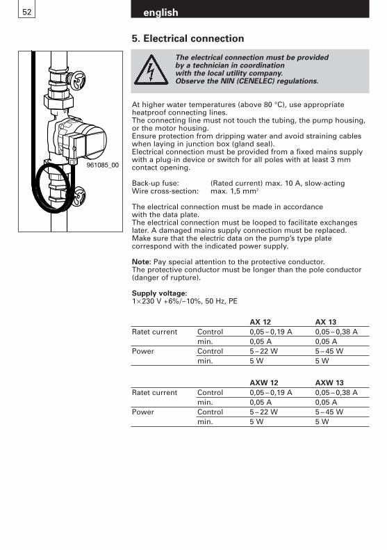
english52
961085_00
The electrical connection must be provided by a technician in coordination with the local utility company.Observe the NIN (CENELEC) regulations.
At higher water temperatures (above 80 °C), use appropriate heatproof connecting lines.The connecting line must not touch the tubing, the pump housing,or the motor housing.Ensure protection from dripping water and avoid straining cableswhen laying in junction box (gland seal).Electrical connection must be provided from a fixed mains supplywith a plug-in device or switch for all poles with at least 3 mmcontact opening.
Back-up fuse: (Rated current) max. 10 A, slow-actingWire cross-section: max. 1,5 mm2
The electrical connection must be made in accordance with the data plate.The electrical connection must be looped to facilitate exchangeslater. A damaged mains supply connection must be replaced. Make sure that the electric data on the pump’s type plate correspond with the indicated power supply.
Note: Pay special attention to the protective conductor.The protective conductor must be longer than the pole conductor(danger of rupture).
Supply voltage: 1× 230 V +6%/–10%, 50 Hz, PE
5. Electrical connection
AX 12 AX 13
Ratet current Control 0,05 – 0,19 A 0,05 – 0,38 Amin. 0,05 A 0,05 A
Power Control 5 – 22 W 5 – 45 Wmin. 5 W 5 W
AXW 12 AXW 13
Ratet current Control 0,05 – 0,19 A 0,05 – 0,38 Amin. 0,05 A 0,05 A
Power Control 5 – 22 W 5 – 45 Wmin. 5 W 5 W
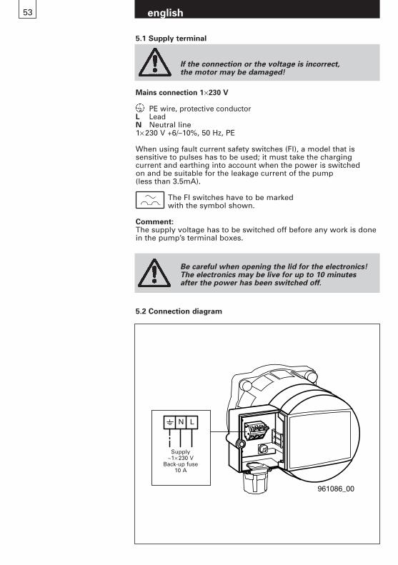
english53
Mains connection 1×230 V
PE wire, protective conductorL LeadN Neutral line1× 230 V +6/–10%, 50 Hz, PE
When using fault current safety switches (FI), a model that is sensitive to pulses has to be used; it must take the charging current and earthing into account when the power is switched on and be suitable for the leakage current of the pump (less than 3.5mA).
The FI switches have to be marked with the symbol shown.
Comment:The supply voltage has to be switched off before any work is donein the pump’s terminal boxes.
5.1 Supply terminal
If the connection or the voltage is incorrect, the motor may be damaged!
Be careful when opening the lid for the electronics!The electronics may be live for up to 10 minutes after the power has been switched off.
961086_00
N L
Speisung ~ 1x230V
Vorsicherung10A
Supply~1× 230 V
Back-up fuse10 A
5.2 Connection diagram

english54
6. Settings
6.1 Setting of control and feed height
Item Description
A Control keyboardB Company nameplate
9610
87_0
0
B A 5 Automatic night reduction Aut.If the forward flow temperature in the system decreases by 10° to 15°C (min. 0.1°C/min.), the pump output is reduced to «min. » after approx. 2 hours.
If the forward flow temperature increases by 10 °C, changeover is made immediately to control operation.LED lights: «Automatic night reduction» function is connected.
Note:– At constant speed I, II or III, the automatic night reduction is deactivated.
The following conditions must be satisfied for the automatic night reduction to function properly:– The pump must be installed in the forward flow
of the heating.It does not function in the return flow.
– The heating must have a control for temperature of the medium.
1 Control key
2 Controlled operation: Proportional pressure (pp)Suggested for the following equipment:– Dual pipe systems with thermal valves and
– long stretches of pipe– valves with a large working area– high pressure loss
– Primary circuit pumps with high pressure loss
3 Controlled operation: Constant pressure (cp)Suggested for the following equipment:– Dual-pipe systems with thermal valves and
– Feed height <2m– Natural circulation (formerly gravity heating)
– with very low pressure loss– Primary circulation pumps in systems
with low pressure loss– Floor heating with thermostatic valves– Single-pipe heating
4 Uncontrolled operation: Constant speed (cs)The operating point can be optimally adjusted by altering the speed (A2 buttons).Suggested for systems with constant volume flow:Air conditioning units, heat pumps, boiler feed pumps, etc.
1
5 6
2 3 4
6 The indication shows the present power consumption of the pump with the mains supply switched on.A malfunction of the pump is indicated with «- -». See section 9 for elimination (fault summary).

55 english
6.3 Control characteristic AX 12, AXW 12
6.4 Control characteristic AX 13, AXW 13
0
0 0
1
H[m]
0
20
0
0
0
10
imp.g.p.m
961158_00
max
min
min
max
20
30
40
50
2
3
4
5
H[kPa]
P [W]
0.5 1 1.5 2 2.5 3 3.5 4 4.5 5 m³/h 6
0.2 0.4 0.6 0.8 1.0 1.2 l/s 1.6
v(1") 0.5 1 1.5 2 2.5
2 4 6 8 10 12 14 20
1
40
60
m/s
H
[m]
max
H
[kPa]
P [W]1
961151_00
min
min
max
Automatic night reduction do not use with wood heating systems, gas heaters, water heaters, storage charging, remote pipes, heat pumps and similar systems.
Warning
6.2 Factory setting of pump
Proportional pressure (PP1) ON
Aut. OFF
56 english
7. Initiation/operating control
7.1 General Flush system thoroughly without pump. See section 4.Fill and de-aerate the system properly.Only put the pump into operation when the system is full.Switch on the distribution voltage.
7.2 VentingVenting of the pump, particularly of the motor space, is performed automatically after a brief period of operation.Running dry briefly (max. 2 mins.) does not harm the motor.It is recommended to run the pump briefly on «max» to ensure rapid venting of the system.
7.3 Operating controlOne LED must always be lit and the present power consumptionmust be displayed.(See section 6.1 item 6)
7.4 DeblockingNot necessary. Motor starts with high torque, see section 8.
There is a danger of scalding
Before performing maintenance on the pump, make sure that the pump is taken out of operation, disconnect all poles from the power grid, and securefrom switching on again.Only have trained staff do this work.
Mind the operating instructions.Only perform this work when the system is at standstill.Take the pump off power.
Switch off the fuse and put on warning signs.
The media in the system may scald you.
The hot surfaces may scald you.
8. Maintenance, servicing
The pump must not be operated without water!Warning
57 english
9. Summary of malfunctions
Switch off all poles of the supply voltage without failbefore removing the terminal box cover and always before dismantling the pump.The electronics can still be live for up to 10 minutes after switching off the power supply!
Fault Cause Remedy
Pump does not run No motor voltage Check switch and fuses, (no LED indication) check supply voltage
Short-circuit Mains supply when switching on pump wrongly connected Connect correctly
Motor defective Change pump
Power consumption Fault in electronics Restart pumpindicates fault « » (switch mains supply ON/OFF) (see section 5.1)
Mains voltage too low Check control and mains
Noises from pump Air in pump Vent system several times with pump switched off.Pump vented automaticallysee sections 6.1
Cavitation Increase system pressure/reduce temperaturesee section 10
Pump too powerful Set lower characteristicsee section 6.1/smaller pump
Radiators do not heat up Pump too weak Set higher characteristic, see section 6.1
fit more powerful pump
Switch off automatic night reduction Aut.
Air in pump Vent system with pump offsee section 7.2
Subject to technical modifications
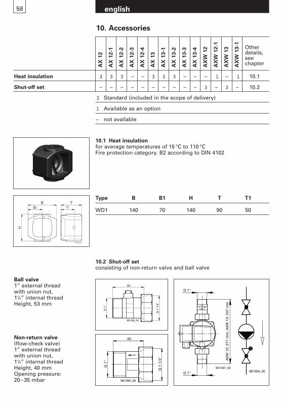
58 english
10. Accessories
AX
12
AX
12-1
AX
12-2
AX
12-3
AX
12-4
AX
13
AX
13-1
AX
13-2
AX
13-3
AX
13-4
AX
W 1
2
AX
W 1
2-1
AX
W 1
3
AX
W 1
3-1 Other
details,seechapter
Heat insulation 3 3 3 – – 3 3 3 – – – l – l 10.1
Shut-off set – – – – – – – – – – 3 – 3 – 10.2
3 Standard (included in the scope of delivery)
l Available as an option
– not available
Ball valve1” external thread with union nut, 11/4” internal threadHeight, 53 mm
Non-return valve (flow-check valve)1” external thread with union nut, 11/4” internal threadHeight, 40 mmOpening pressure: 20–35 mbar
961194_00
BB1 T1
T
H
10.1 Heat insulationfor average temperatures of 15 °C to 110 °CFire protection category. B2 according to DIN 4102
Type B B1 H T T1
WD1 140 70 140 90 50
10.2 Shut-off setconsisting of non-return valve and ball valve
G 1
"
G 1
1/4
"
40
961395_00
G 1"
G 1"961397_00
AX
W 1
2: 2
17 m
m, A
XW
13:
247
mm
G 1
"
G 1
1/4
"
53
961396_00
961394_00
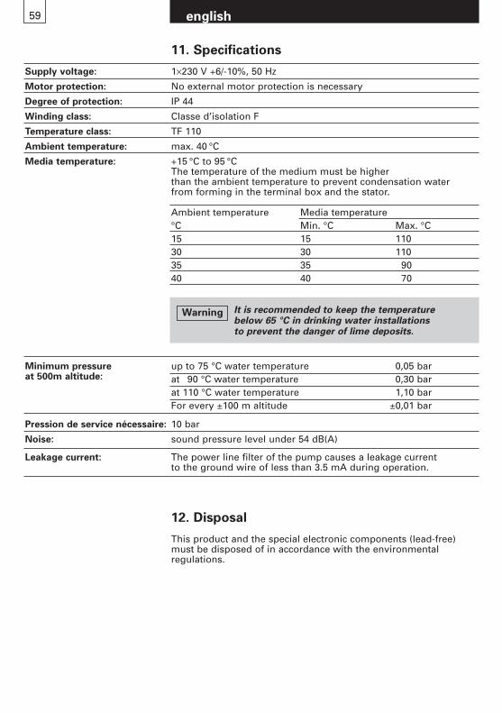
59 english
11. Specifications
Supply voltage: 1×230 V +6/-10%, 50 Hz
Motor protection: No external motor protection is necessary
Degree of protection: IP 44
Winding class: Classe d’isolation F
Temperature class: TF 110
Ambient temperature: max. 40 °C
Media temperature: +15 °C to 95 °CThe temperature of the medium must be higher than the ambient temperature to prevent condensation water from forming in the terminal box and the stator.
up to 75 °C water temperature 0,05 barat 90 °C water temperature 0,30 barat 110 °C water temperature 1,10 barFor every ±100 m altitude ±0,01 bar
Pression de service nécessaire: 10 bar
Noise: sound pressure level under 54 dB(A)
Leakage current: The power line filter of the pump causes a leakage current to the ground wire of less than 3.5 mA during operation.
Minimum pressure at 500m altitude:
Ambient temperature Media temperature°C Min. °C Max. °C15 15 11030 30 11035 35 9040 40 70
12. Disposal
This product and the special electronic components (lead-free)must be disposed of in accordance with the environmental regulations.
It is recommended to keep the temperature below 65 °C in drinking water installations to prevent the danger of lime deposits.
Warning

Inhoud
1. Veiligheidsinstructies pagina 621.1 Algemeen 621.2 Verklaring van de symbolen 621.3 Gekwalificeerd personeel en opleiding 621.4 Gevaar bij niet opvolgen
van veiligheidsinstructies 621.5 Uitvoering volgens veiligheidsnormen 631.6 Veiligheidsinstructies voor uitvoerder/gebruiker 631.7 Veiligheidsinstructies voor montage-,
onderhouds- en inspectiewerkzaamheden 631.8 Aanpassingen en reserveonderdelen 631.9 Andere toepassingen/gebruik 63
2. Transport/opslag 63
3. Toepassing 643.1 Medium 643.2 Bedrijfstemperatuur/bedrijfsdruk 64
4. Montage 644.1 Doorspoelen van de installatie 644.2 Vorstbeveiliging 644.3 Inbouw 644.4 Montagepositie 654.5 Terugslagklep 654.6 Minimale statische druk 65
5. Elektrische aansluiting 665.1 Aansluitklemmen 675.2 Aansluitschema, Standaarduitvoering 67
6. Instellingen 686.1 Instellen van de regeling ++++ 686.2 Standaardinstelling van de pomp 696.3 Pompkarakteristiek AX 12, AXW 12 706.4 Pompkarakteristiek AX 13, AXW 13 70
7. In bedrijf nemen/bedrijfscontrole 717.1 Algemeen 717.2 Ontluchten 717.3 Bedrijfscontrole 717.4 Deblokkeren 71
8. Onderhoud, service 71
9. Storingsoverzicht 72
10. Toebehoren 7310.1 Warmte isolatieschalen 7310.2 Afsluiterset 73
11. Technische gegevens 74
12. Afvalverwerking 74
nederlands61
nederlands62
1. Veiligheidsinstructies
1.1 AlgemeenDeze montage- en bedrijfshandleiding bevat belangrijke aanwijzigingen die bij montage, bedrijf en onderhoud opgevolgd moeten worden. Deze moeten voor montage eninbedrijfname, door zowel monteur als verantwoordelijke technici/gebruiker, volledig gelezen worden. Deze handleidingmoet altijd bij de installatie aanwezig zijn. Extra aandacht voorde onder «veiligheidsinstructies» (hoofdstuk 1) opgenomenalgemene veiligheidsinstructies, als ook in de andere hoofd-stukken omschreven speciale veiligheidsinstructies.
1.2 Verklaring van de symbolen
Op de pomp/installatie aangebrachte instructie zoals bijvoorbeeld:
- draairichtingsaanduiding- aanduiding voor leidingaansluitingen moeten opgevolgd en
altijd volledig leesbaar blijven.
1.3 Gekwalificeerd personeel en opleidingPersoneel, verantwoordelijk voor de montage, bediening,onderhoud en inspectie moet hiervoor gekwalificeerd zijn.Verantwoordelijkheden/bevoegdheden en de controle van personeel moet door de uitvoerder/gebruiker nauwkeurigbepaald zijn.
1.4 Gevaar bij niet opvolgen van veiligheidsinstructiesNiet opvolgen van de veiligheidsinstructies kan gevaar voormensen, omgeving, milieu en pomp/installatie opleveren. Bij niet opvolgen van de veiligheidsinstructies vervalt elke vormvan aansprakelijkheid.
Dit symbool betekent waarschuwing voor gevaar-lijke elektrische spanning. «Veiligheidssymboolvolgens DIN 4844-W8».
Veiligheidsinstructies, die met niet, of onjuist opvolgen, gevaar voor mensen kunnen opleverenzijn in deze montage- en bedrijfshandleiding aangegeven met het «algemene gevaren-symbool, volgens DIN 4844-W9».
Dit symbool treft u aan bij veiligheidsinstructies die bij niet of onjuist opvolgen gevaar (schade)voor de pomp/installatie en de werking ervankunnen opleveren.
Pas op
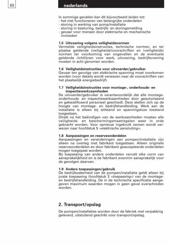
63
In sommige gevallen kan dit bijvoorbeeld leiden tot:- het niet functioneren van belangrijke onderdelen- storing in werking van pomp/installatie- storing in besturing, bedrijfs- en storingsmelding- gevaar voor mensen door elektrische en mechanische
invloeden
1.5 Uitvoering volgens veiligheidsnormenVermelde veiligheidsinstructies, technische normen, en terplaatse geldende (veiligheids)voorschriften en (veiligheids) normen ter voorkoming van ongevallen en de eventuele geldende richtlijnen voor werk, uitvoering, bedrijfsvoering moeten in acht genomen worden.
1.6 Veiligheidsinstructies voor uitvoerder/gebruikerGevaar ten gevolge van elektrische spanning moet voorkomenworden (voor details wordt verwezen naar de voorschriften vanhet plaatselijk energiebedrijf).
1.7 Veiligheidsinstructies voor montage-, onderhouds- eninspectiewerkzaamheden
De uitvoerder/gebruiker is verantwoordelijk dat alle montage-onderhouds- en inspectiewerkzaamheden door geautoriseerden gekwalificeerd personeel geschiedt. Deze stellen zich op dehoogte van montage- en bedrijfshandleiding. Werk aan deinstallatie is alleen bij stilstand en spanningsloze toestand toegestaan.Direkt na het beëindigen van de werkzaamheden moeten alleveiligheids- en beschermingsmaatregelen weer in ordegebracht worden. Voor opnieuw ingebruik nemen wordt ver-wezen naar hoofdstuk 5 «elektrische aansluiting».
1.8 Aanpassingen en reserveonderdelenAanpassingen en veranderingen aan pompen/installatie zijnalleen na overleg met fabrikant toegestaan. Alleen originelereserveonderdelen en door fabrikant geaccepteerde onderdelenmogen toegepast worden.Bij toepassing van andere onderdelen vervalt elke vorm vanaansprakelijkheid en is de fabrikant evenmin aansprakelijk voorde gevolgen daarvan.
1.9 Andere toepassingen/gebruikDe bedrijfszekerheid van de pompen/installatie geldt alleen bijjuiste toepassing (hoofdstuk 3 «toepassing») van de montage-en bedrijfshandleiding. De in de technische specificatie aange-geven maximum waarden mogen in geen geval overschredenworden.
nederlands
2. Transport/opslag
De pompen/installaties worden door de fabriek met verpakkinggeleverd, uitsluitend geschikt voor transport/opslag.
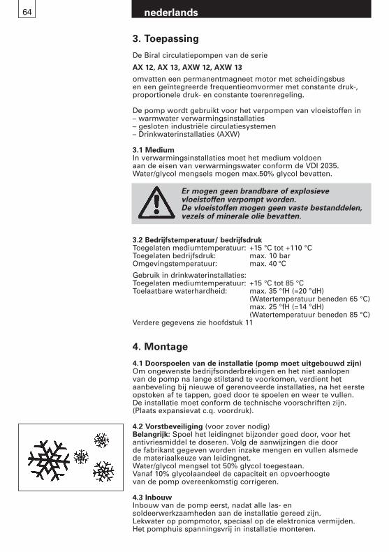
nederlands64
4. Montage
4.1 Doorspoelen van de installatie (pomp moet uitgebouwd zijn)Om ongewenste bedrijfsonderbrekingen en het niet aanlopen van de pomp na lange stilstand te voorkomen, verdient het aanbeveling bij nieuwe of gerenoveerde installaties, na het eersteopstoken af te tappen, goed door te spoelen en weer te vullen.De installatie moet conform de technische voorschriften zijn.(Plaats expansievat c.q. voordruk).
4.2 Vorstbeveiliging (voor zover nodig)Belangrijk: Spoel het leidingnet bijzonder goed door, voor het antivriesmiddel te doseren. Volg de aanwijzingen die door de fabrikant gegeven worden inzake mengen en vullen alsmede de materiaalkeuze van leidingnet.Water/glycol mengsel tot 50% glycol toegestaan. Vanaf 10% glycolaandeel de capaciteit en opvoerhoogte van de pomp overeenkomstig corrigeren.
4.3 InbouwInbouw van de pomp eerst, nadat alle las- en soldeerwerkzaamheden aan de installatie gereed zijn. Lekwater op pompmotor, speciaal op de elektronica vermijden.Het pomphuis spanningsvrij in installatie monteren.
3.2 Bedrijfstemperatuur/ bedrijfsdrukToegelaten mediumtemperatuur: +15 °C tot +110 °CToegelaten bedrijfsdruk: max. 10 barOmgevingstemperatuur: max. 40 °C
Gebruik in drinkwaterinstallaties:Toegelaten mediumtemperatuur: +15 °C tot 85 °CToelaatbare waterhardheid: max. 35 °fH (=20 °dH)
(Watertemperatuur beneden 65 °C)max. 25 °fH (=14 °dH) (Watertemperatuur beneden 85 °C)
Verdere gegevens zie hoofdstuk 11
Er mogen geen brandbare of explosieve vloeistoffen verpompt worden.De vloeistoffen mogen geen vaste bestanddelen, vezels of minerale olie bevatten.
3. Toepassing
De Biral circulatiepompen van de serie
AX 12, AX 13, AXW 12, AXW 13
omvatten een permanentmagneet motor met scheidingsbusen een geïntegreerde frequentieomvormer met constante druk-,proportionele druk- en constante toerenregeling.
De pomp wordt gebruikt voor het verpompen van vloeistoffen in– warmwater verwarmingsinstallaties– gesloten industriële circulatiesystemen– Drinkwaterinstallaties (AXW)
3.1 MediumIn verwarmingsinstallaties moet het medium voldoen aan de eisen van verwarmingswater conform de VDI 2035.Water/glycol mengsels mogen max.50% glycol bevatten.
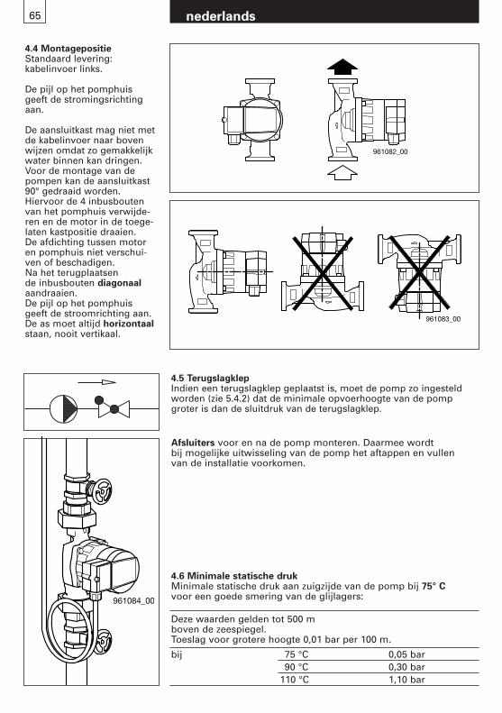
4.6 Minimale statische drukMinimale statische druk aan zuigzijde van de pomp bij 75° C voor een goede smering van de glijlagers:
Deze waarden gelden tot 500 m boven de zeespiegel.Toeslag voor grotere hoogte 0,01 bar per 100 m.
bij 75 °C 0,05 bar90 °C 0,30 bar
110 °C 1,10 bar
4.4 MontagepositieStandaard levering: kabelinvoer links.
De pijl op het pomphuis geeft de stromingsrichtingaan.
De aansluitkast mag niet metde kabelinvoer naar bovenwijzen omdat zo gemakkelijkwater binnen kan dringen.Voor de montage van de pompen kan de aansluitkast90° gedraaid worden. Hiervoor de 4 inbusboutenvan het pomphuis verwijde-ren en de motor in de toege-laten kastpositie draaien. De afdichting tussen motor en pomphuis niet verschui-ven of beschadigen. Na het terugplaatsen de inbusbouten diagonaalaandraaien.De pijl op het pomphuis geeft de stroomrichting aan.De as moet altijd horizontaalstaan, nooit vertikaal.
nederlands65
4.5 TerugslagklepIndien een terugslagklep geplaatst is, moet de pomp zo ingesteldworden (zie 5.4.2) dat de minimale opvoerhoogte van de pomp groter is dan de sluitdruk van de terugslagklep.
Afsluiters voor en na de pomp monteren. Daarmee wordt bij mogelijke uitwisseling van de pomp het aftappen en vullen van de installatie voorkomen.
961082_00
961083_00
961084_00
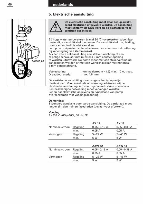
De elektrische aansluiting moet door een gekwalifi-ceerd elektriciën uitgevoerd worden. De aansluitingmoet conform de NEN 1010 en de plaatselijke voor-schriften geschieden.
Bij hoge watertemperaturen (vanaf 80 °C) overeenkomstige hitte-bestendige aansluitkabel toepassen. De aansluitkabel mag leiding,pomp- en motorhuis niet aanraken.Let op de druipwaterdichte kabelinvoer voorzien van trekontlastingbij kabelingang van klemmenkast.Als een vaste net-aansluiting een stekker-inrichting of een al-polige schakelaar met minstens 3 mm contact-opening te worden uitgevoerd. De pomp moet met een stekerverbindingaangesloten worden of met een werkschakelaar met minimaal 3 mm contactafstand.
Voorzekering: nominaalstroom ×1,5) max. 10 A, traag.Draaddoorsnede: max. 1,5 mm2
De elektrische aansluiting moet volgens het typeplaatje plaatsvinden. Voor eventuele uitwisseling adviseren wij de elektrische aansluiting van een zogenaamde «lus» te voorzien.Een beschadigde netvoeding moet vervangen worden.Let op dat elektrische gegevens op typeplaatje van pomp overeenkomen met voedingsspanning.
Opmerking:Bijzondere aandacht voor aarde aansluiting. De aarddraad moetlanger zijn dan nul- en fasedraden (gevaar voor afbreken).
Voeding1× 230 V +6%/–10%, 50 Hz, PE
nederlands66
961085_00
5. Elektrische aansluiting
AX 12 AX 13
Nominaalstroom Regeling 0,05 – 0,19 A 0,05 – 0,38 Amin. 0,05 A 0,05 A
Vermogen Regeling 5 – 22 W 5 – 45 Wmin. 5 W 5 W
AXW 12 AXW 13
Nominaalstroom Regeling 0,05 – 0,19 A 0,05 – 0,38 Amin. 0,05 A 0,05 A
Vermogen Regeling 5 – 22 W 5 – 45 Wmin. 5 W 5 W
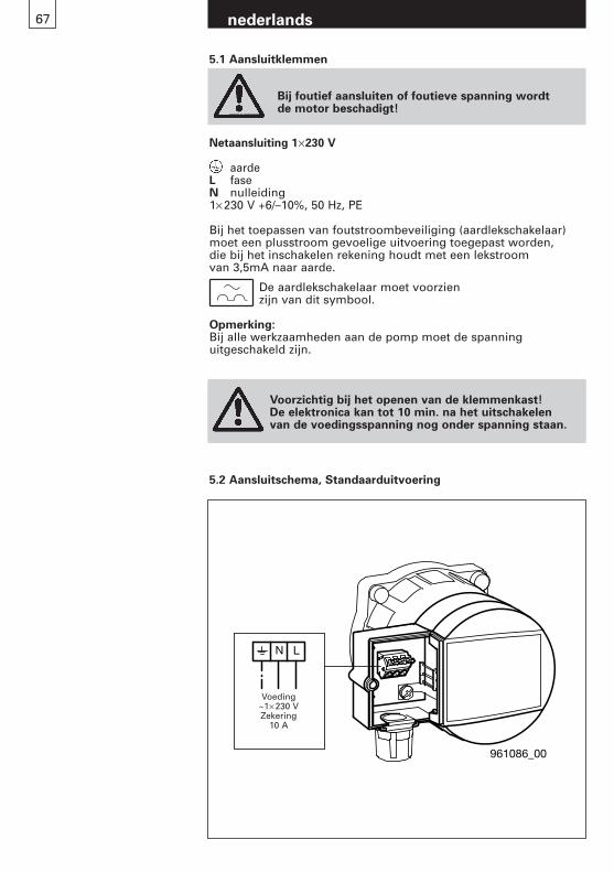
nederlands67
Attention lors de l’ouverture du couvercle de l’électronique! L’électronique peut rester sous tension jusqu’à 10 minutes après le déclenchement du courant.
Netaansluiting 1×230 V
aardeL faseN nulleiding1× 230 V +6/–10%, 50 Hz, PE
Bij het toepassen van foutstroombeveiliging (aardlekschakelaar)moet een plusstroom gevoelige uitvoering toegepast worden, die bij het inschakelen rekening houdt met een lekstroom van 3,5mA naar aarde.
De aardlekschakelaar moet voorzien zijn van dit symbool.
Opmerking:Bij alle werkzaamheden aan de pomp moet de spanning uitgeschakeld zijn.
5.1 Aansluitklemmen
Bij foutief aansluiten of foutieve spanning wordt de motor beschadigt!
Voorzichtig bij het openen van de klemmenkast!De elektronica kan tot 10 min. na het uitschakelen van de voedingsspanning nog onder spanning staan.
961086_00
N L
Speisung ~ 1x230V
Vorsicherung10A
Voeding~1× 230 VZekering
10 A
5.2 Aansluitschema, Standaarduitvoering
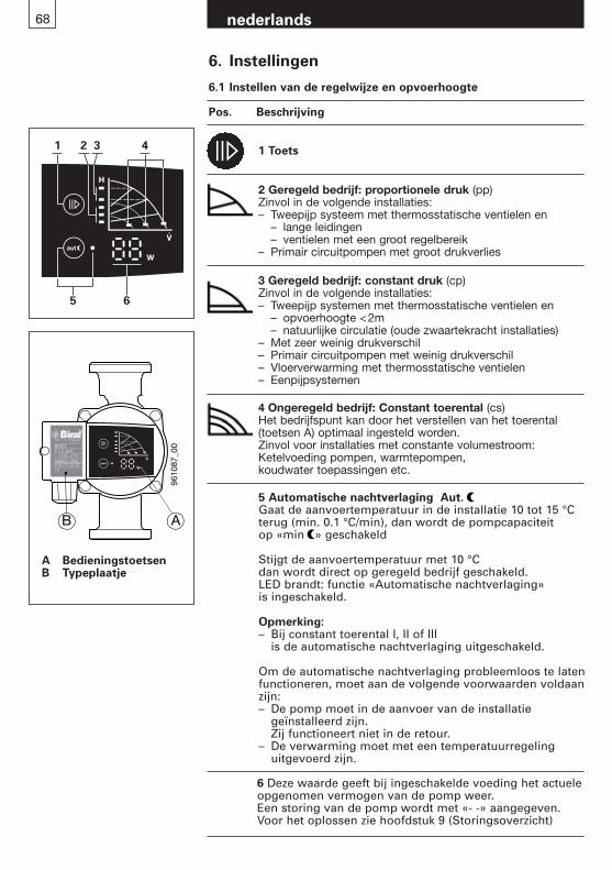
68 nederlands
6. Instellingen
6.1 Instellen van de regelwijze en opvoerhoogte
Pos. Beschrijving
A BedieningstoetsenB Typeplaatje
9610
87_0
0
B A
5 Automatische nachtverlaging Aut.Gaat de aanvoertemperatuur in de installatie 10 tot 15 °C terug (min. 0.1 °C/min), dan wordt de pompcapaciteit op «min » geschakeld
Stijgt de aanvoertemperatuur met 10 °C dan wordt direct op geregeld bedrijf geschakeld.LED brandt: functie «Automatische nachtverlaging» is ingeschakeld.
Opmerking:– Bij constant toerental I, II of III
is de automatische nachtverlaging uitgeschakeld.
Om de automatische nachtverlaging probleemloos te laten functioneren, moet aan de volgende voorwaarden voldaan zijn:– De pomp moet in de aanvoer van de installatie
geïnstalleerd zijn. Zij functioneert niet in de retour.
– De verwarming moet met een temperatuurregeling uitgevoerd zijn.
1 Toets
2 Geregeld bedrijf: proportionele druk (pp)Zinvol in de volgende installaties:– Tweepijp systeem met thermosstatische ventielen en
– lange leidingen– ventielen met een groot regelbereik
– Primair circuitpompen met groot drukverlies
3 Geregeld bedrijf: constant druk (cp)Zinvol in de volgende installaties:– Tweepijp systemen met thermosstatische ventielen en
– opvoerhoogte <2m – natuurlijke circulatie (oude zwaartekracht installaties)
– Met zeer weinig drukverschil– Primair circuitpompen met weinig drukverschil– Vloerverwarming met thermosstatische ventielen– Eenpijpsystemen
4 Ongeregeld bedrijf: Constant toerental (cs)Het bedrijfspunt kan door het verstellen van het toerental(toetsen A) optimaal ingesteld worden.Zinvol voor installaties met constante volumestroom:Ketelvoeding pompen, warmtepompen, koudwater toepassingen etc.
1
5 6
2 3 4
6 Deze waarde geeft bij ingeschakelde voeding het actuele opgenomen vermogen van de pomp weer.Een storing van de pomp wordt met «- -» aangegeven.Voor het oplossen zie hoofdstuk 9 (Storingsoverzicht)
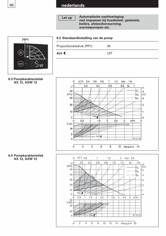
69 nederlands
6.3 Pompkarakteristiek AX 12, AXW 12
6.4 Pompkarakteristiek AX 13, AXW 13
0
0 0
1
H[m]
0
20
0
0
0
10
imp.g.p.m
961158_00
max
min
min
max
20
30
40
50
2
3
4
5
H[kPa]
P [W]
0.5 1 1.5 2 2.5 3 3.5 4 4.5 5 m³/h 6
0.2 0.4 0.6 0.8 1.0 1.2 l/s 1.6
v(1") 0.5 1 1.5 2 2.5
2 4 6 8 10 12 14 20
1
40
60
m/s
H
[m]
max
H
[kPa]
P [W]1
961151_00
min
min
max
6.2 Standaardinstelling van de pomp
Proportioneledruk (PP1) IN
Aut. UIT
Automatische nachtverlagingniet toepassen bij houtketels, gasketels, boilers, afstandverwarming,warmtepompen etc.
Let op
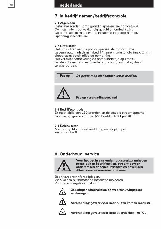
70 nederlands
7.3 BedrijfscontroleEr moet altijd een LED branden en de actuele stroomopname moet aangegeven worden. (Zie hoofdstuk 6.1 pos 6)
7.4 DeblokkerenNiet nodig. Motor start met hoog aanloopkoppel, zie hoofdstuk 8.
Pas op verbrandingsgevaar!
Voor het begin van onderhoudswerkzaamhedenpomp buiten bedrijf stellen, stroomtoevoer onderbreken en tegen inschakelen beveiligen.Alleen door vakmensen uitvoeren.
Bedrijfsvoorschrift raadplegen.Werk alleen bij stilstaande installatie uitvoeren.Pomp spanningsloos maken.
Zekeringen uitschakelen en waarschuwingsbord aanbrengen.
Verbrandingsgevaar door naar buiten komen medium.
Verbrandingsgevaar door hete opervlakken (80 °C).
8. Onderhoud, service
7. In bedrijf nemen/bedrijfscontrole
7.1 AlgemeenInstallatie zonder pomp grondig spoelen, zie hoofdstuk 4.De installatie moet vakkundig gevuld en ontlucht zijn. De pomp alleen met gevulde installatie in bedrijf nemen. Spanning inschakelen.
7.2 OntluchtenHet ontluchten van de pomp, speciaal de motorruimte, gebeurt automatisch na inbedrijf nemen, kortstondig (max. 2 min)drooglopen beschadigd de pomp niet.Het verdient aanbeveling de pomp korte tijd op «max.» te laten draaien, om een snelle ontluchting van het systeem te waarborgen.
De pomp mag niet zonder water draaien!Pas op
71 nederlands
9. Storingsoverzicht
Voor het verwijderen van het klemmenkastdeksel en voor demontage van de pomp de voedingsspan-ning uitschakelen. De elektronica kan tot 10 minuten na het uitschakelen van de voeding onder spanningstaan.
Storing Oorzaak Oplossing
Pomp loopt niet Geen spanning op de motor Schakelaar en zekeringen (geen LED signaal) controleren.
Voedingsspanning testen
Kortsluiting bij het inschakelen Voedingvan de pomp foutief aangesloten Juist aansluiten
Motor defect Pomp uitwisselen
Opgenomen vermogen Fout in elektronica Pomp opnieuw startensignaleert storing « » (Voeding IN/UIT schakelen) (zie hoofdstuk 5.1)
Te lage voedingsspanning Regeling en voeding controleren
Pomp maakt lawaai Lucht in de pomp Installatie ontluchten bij stilstaande pomp. Pomp ontlucht zichzelf, zie hoofdstuk 6.2
Kavitatie Systeemdruk verhogen/temperatuur verlagen, zie hoofdstuk 10.
Pomp te sterk Lagere regelkarakteristiek kiezen, zie hoofdstuk 5.4
Radiatoren worden niet warm Pomp te zwak Hogere regelkarakteristiek kiezen, zie hoofdstuk 5.4
Grotere pomp inbouwen
Automatische nachtverlaging Aut. uitschakelen
Lucht in de pomp Installatie ontluchten bij stilstaande pomp, zie hoofdstuk 6.2
Technische wijzigingen voorbehouden
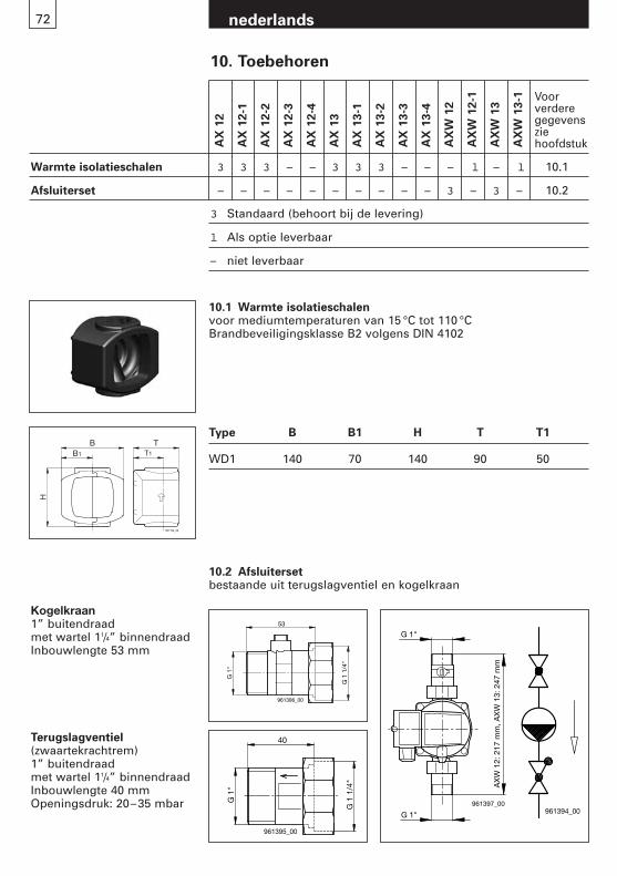
10. Toebehoren
AX
12
AX
12-1
AX
12-2
AX
12-3
AX
12-4
AX
13
AX
13-1
AX
13-2
AX
13-3
AX
13-4
AX
W 1
2
AX
W 1
2-1
AX
W 1
3
AX
W 1
3-1 Voor
verderegegevenszie hoofdstuk
Warmte isolatieschalen 3 3 3 – – 3 3 3 – – – l – l 10.1
Afsluiterset – – – – – – – – – – 3 – 3 – 10.2
3 Standaard (behoort bij de levering)
l Als optie leverbaar
– niet leverbaar
Kogelkraan1” buitendraadmet wartel 11/4” binnendraadInbouwlengte 53 mm
Terugslagventiel (zwaartekrachtrem)1” buitendraad met wartel 11/4” binnendraadInbouwlengte 40 mmOpeningsdruk: 20–35 mbar
961194_00
BB1 T1
T
H
10.1 Warmte isolatieschalenvoor mediumtemperaturen van 15 °C tot 110 °CBrandbeveiligingsklasse B2 volgens DIN 4102
Type B B1 H T T1
WD1 140 70 140 90 50
10.2 Afsluitersetbestaande uit terugslagventiel en kogelkraan
nederlands72
G 1
"
G 1
1/4
"
40
961395_00
G 1"
G 1"961397_00
AX
W 1
2: 2
17 m
m, A
XW
13:
247
mm
G 1
"
G 1
1/4
"
53
961396_00
961394_00
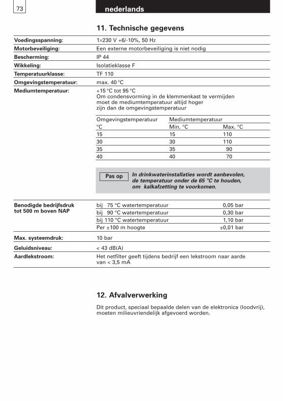
nederlands73
11. Technische gegevens
Voedingsspanning: 1×230 V +6/-10%, 50 Hz
Motorbeveiliging: Een externe motorbeveiliging is niet nodig
Bescherming: IP 44
Wikkeling: Isolatieklasse F
Temperatuurklasse: TF 110
Omgevingstemperatuur: max. 40 °C
Mediumtemperatuur: +15 °C tot 95 °COm condensvorming in de klemmenkast te vermijden moet de mediumtemperatuur altijd hoger zijn dan de omgevingstemperatuur
bij 75 °C watertemperatuur 0,05 barbij 90 °C watertemperatuur 0,30 barbij 110 °C watertemperatuur 1,10 barPer ±100 m hoogte ±0,01 bar
Max. systeemdruk: 10 bar
Geluidsniveau: < 43 dB(A)
Aardlekstroom: Het netfilter geeft tijdens bedrijf een lekstroom naar aarde van < 3,5 mA
Benodigde bedrijfsdruktot 500 m boven NAP
Omgevingstemperatuur Mediumtemperatuur°C Min. °C Max. °C15 15 11030 30 11035 35 9040 40 70
12. Afvalverwerking
Dit product, speciaal bepaalde delen van de elektronica (loodvrij),moeten milieuvriendelijk afgevoerd worden.
In drinkwaterinstallaties wordt aanbevolen,de temperatuur onder de 65 °C te houden,om kalkafzetting te voorkomen.
Pas op

Indice
1. Instrucciones de seguridad Pág. 761.1 Generalidades 761.2 Caracterización de las advertencias 761.3 Cualificación y formación del personal 761.4 Peligros en caso de inobservancia
de las instrucciones de seguridad 761.5 Trabajo con consciencia de la seguridad 771.6 Instrucciones de seguridad para el explotador/usuario 771.7 Instrucciones de seguridad para los trabajos
de montaje, mantenimiento e inspección 771.8 Transformaciones y fabricación no autorizadas
de piezas de repuesto 771.9 Modos de funcionamiento no autorizados 77
2. Transporte/Almacenamiento 77
3. Finalidad de uso 783.1 Medio de transporte 783.2 Temperatura y presión de servicio 78
4. Montaje 784.1 Limpieza de la instalación de calefacción 784.2 Anticongelante 784.3 Montaje 784.4 Posición de montaje 794.5 Válvula de retención 794.6 Presión mínima 79
5. Conexión eléctrica 805.1 Bornes de conexión 815.2 Esquema de conexiones en ejecución estándar 81
6. Ajuste 826.1 Ajuste de la regulación y altura de impulsión 826.2 Ajuste por defecto de la bomba 11 836.3 Curva característica de regulación AX 12, AXW 12 836.4 Curva característica de regulación AX 13, AXW 13 83
7. Puesta en servicio/control de funcionamiento 847.1 Informaciones generales 847.2 Purga de aire 847.3 Control de funcionamiento 847.4 Desbloqueo 84
8. Mantenimiento, servicio 84
9. Lista general de averías 85
10. Accesorios 8610.1 Cubiertas aislantes térmicas 8610.2 Set de bloqueo 86
11. Características técnicas 87
12. Eliminación 87
75 español
español76
1. Instrucciones de seguridad
1.1 GeneralidadesEstas instrucciones de montaje y de funcionamiento contienenadvertencias básicas que han de observarse durante elmontaje, el funcionamiento y el mantenimiento. Por esta razón,el técnico de montaje, el personal técnico responsable y elexplotador han de leerlas antes del montaje y la puesta en marcha. Estas instrucciones deberán estar siempre disponiblesen el lugar de la instalación.Además de las advertencias generales expuestas en esta sección de instrucciones de seguridad, se observarán lasinstrucciones específicas expuestas en las demás secciones.
1.2 Caracterización de las advertencias
Las advertencias colocadas directamente en la máquina, comopor ejemplo- flecha de sentido de circulación- signo para conexión de fluidoshan de respetarse escrupulosamente y se las mantendrán en unestado que permita leerlas con facilidad.
1.3 Cualificación y formación del personalEl personal del montaje, servicio, mantenimiento e inspeccióndeberá estar debidamente cualificado para dichos trabajos. El explotador regulará exactamente la responsabilidad, la competencia y la vigilancia del personal.
1.4 Peligros en caso de inobservancia de las instrucciones de seguridad
En caso de inobservancia de las instrucciones de seguridadpuede surgir peligro tanto para las personas como para elmedio ambiente y para la instalación. La no observancia de lasinstrucciones de seguridad puede tener como consecuencia lapérdida de todo derecho de indemnización por daños y perjuicios.
Este símbolo advierte contra tensión eléctrica peligrosa.«Signo de seguridad según DIN 4844-W8».
Las advertencias de seguridad contenidas enestas instrucciones de montaje y funcionamiento,que en caso de inobservancia pueden provocar peligro para las personas, están caracterizadas expresamente con el símbolo general de peligro«Signo de seguridad según DIN 4844-W9».
Este signo lo encontrará usted en las instruc-ciones de seguridad cuya no observancia puedeprovocar peligros para la máquina y su funcio-namiento.
Atención
español77
La inobservancia de las instrucciones de seguridad puede provocar, en concreto, los peligros siguientes:- fallo de funciones importantes de la instalación- fallo de los modelos prescritos para el mantenimiento y
la conservación- peligros para las personas por efectos eléctricos y mecánicos
1.5 Trabajo con consciencia de la seguridadSe observarán las instrucciones de seguridad contenidas enestas instrucciones de montaje y servicio, las prescripcionessobre prevención de accidentes vigentes en el país, así como lasnormas de trabajo, funcionamiento y servicio propias del explotador.
1.6 Instrucciones de seguridad para el explotador/usuarioSe excluirán los peligros por causa de la energía eléctrica (paradetalles sobre este tema véanse, p. ej., las normas NIN (CENELEC) y de las empresas locales de abastecimiento eléctrico).
1.7 Instrucciones de seguridad para los trabajos de montaje,mantenimiento e inspección
El explotador deberá cuidar de que todos los trabajos de montaje, mantenimiento e inspección se realicen por personalespecializado cualificado, suficientemente informado medianteel estudio profundo de las instrucciones de montaje y servicio.En principio, los trabajos en la instalación se harán siempre conla instalación parada y sin tensión.Inmediatamente después de terminar los trabajos volverán aconectarse o a ponerse en funcionamiento todos los disposi-tivos de seguridad y de protección.Antes de la nueva puesta en servicio habrán de observarse lospuntos presentados en la sección Conexión eléctrica.
1.8 Modificaciones y fabricación no autorizadas de piezas de repuesto
La transformación o los cambios en las bombas quedan autorizados únicamente después de consulta con el fabricante.Los repuestos originales y los accesorios autorizados por elfabricante favorecen la seguridad.El empleo de otras piezas puede llevar a que se rechace cualquier responsabilidad por las consecuencias originadas.
1.9 Modos de funcionamiento no autorizadosLa seguridad de servicio de las bombas suministradas estágarantizada únicamente bajo la condición de un uso adecuadoa la finalidad prevista, según la sección Finalidad de uso de lasinstrucciones de montaje y servicio. En ningún caso se supe-rarán los valores límite indicados en los datos técnicos.
2. Transporte/Almacenamiento
Las bombas salen de fábrica embaladas convenientemente.
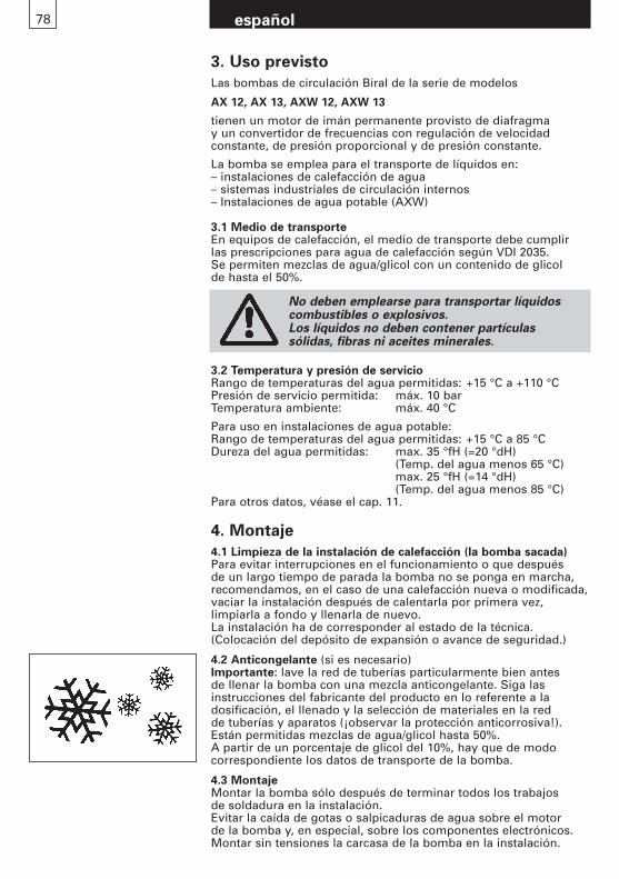
78 español
4. Montaje
4.1 Limpieza de la instalación de calefacción (la bomba sacada)Para evitar interrupciones en el funcionamiento o que despuésde un largo tiempo de parada la bomba no se ponga en marcha,recomendamos, en el caso de una calefacción nueva o modificada,vaciar la instalación después de calentarla por primera vez, limpiarla a fondo y llenarla de nuevo.La instalación ha de corresponder al estado de la técnica.(Colocación del depósito de expansión o avance de seguridad.)
4.2 Anticongelante (si es necesario)Importante: lave la red de tuberías particularmente bien antes de llenar la bomba con una mezcla anticongelante. Siga las instrucciones del fabricante del producto en lo referente a la dosificación, el llenado y la selección de materiales en la red de tuberías y aparatos (¡observar la protección anticorrosiva!).Están permitidas mezclas de agua/glicol hasta 50%.A partir de un porcentaje de glicol del 10%, hay que de modo correspondiente los datos de transporte de la bomba.
4.3 MontajeMontar la bomba sólo después de terminar todos los trabajos de soldadura en la instalación.Evitar la caída de gotas o salpicaduras de agua sobre el motor de la bomba y, en especial, sobre los componentes electrónicos.Montar sin tensiones la carcasa de la bomba en la instalación.
3.2 Temperatura y presión de servicioRango de temperaturas del agua permitidas: +15 °C a +110 °CPresión de servicio permitida: máx. 10 barTemperatura ambiente: máx. 40 °C
Para uso en instalaciones de agua potable:Rango de temperaturas del agua permitidas: +15 °C a 85 °CDureza del agua permitidas: max. 35 °fH (=20 °dH)
(Temp. del agua menos 65 °C)max. 25 °fH (=14 °dH) (Temp. del agua menos 85 °C)
Para otros datos, véase el cap. 11.
No deben emplearse para transportar líquidos combustibles o explosivos. Los líquidos no deben contener partículas sólidas, fibras ni aceites minerales.
3. Uso previsto
Las bombas de circulación Biral de la serie de modelos
AX 12, AX 13, AXW 12, AXW 13
tienen un motor de imán permanente provisto de diafragma y un convertidor de frecuencias con regulación de velocidad constante, de presión proporcional y de presión constante.
La bomba se emplea para el transporte de líquidos en:– instalaciones de calefacción de agua– sistemas industriales de circulación internos– Instalaciones de agua potable (AXW)
3.1 Medio de transporteEn equipos de calefacción, el medio de transporte debe cumplir las prescripciones para agua de calefacción según VDI 2035.Se permiten mezclas de agua/glicol con un contenido de glicol de hasta el 50%.
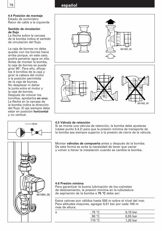
español79
4.4 Posición de montajeEstado de suministroRacor de cable a la izquierda
Sentido de circulación de flujo La flecha sobre la carcasa de la bomba indica el sentido de circulación del flujo.
La caja de bornes no debequedar con los bornes haciaarriba porque, en este caso,podría penetrar agua en ella.Antes de montar la bomba, la caja de bornes se puedegirar 90°. Para ello, aflojar los 4 tornillos de la caja ygirar la cabeza del motor a la posición permitida de la caja de bornes.No desplazar ni dañar la junta entre el motor y la caja de bornes.Después de colocar los tornillos, apretarlos en cruz.La flecha en la carcasa de la bomba indica la direccióndel flujo. El eje siempre debeestar en posición horizontaly no vertical.
4.5 Válvula de retenciónSi se monta una válvula de retención, la bomba debe ajustarse(véase punto 5.4.2) para que la presión mínima de transporte de la bomba sea siempre superior a la presión de cierre de la válvula.
Montar válvulas de compuerta antes y después de la bomba. De esta forma se evita la necesidad de tener que vaciar y volver a llenar la instalación cuando se cambia la bomba.
961082_00
961083_00
961084_00
4.6 Presión mínimaPara garantizar la buena lubricación de los cojinetes de deslizamiento, la presión mínima en la tubuladura de aspiración de la bomba a 75 °C debe ser:
Estos valores son válidos hasta 500 m sobre el nivel del mar.Para altitudes mayores, agregar 0,01 bar por cada 100 m más de altura.
a 75 °C 0,10 bar90 °C 0,55 bar
110 °C 1,20 bar
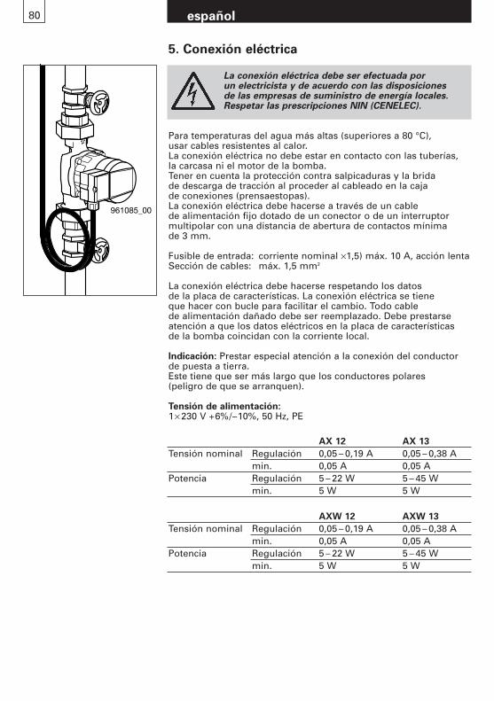
español80
961085_00
5. Conexión eléctrica
La conexión eléctrica debe ser efectuada por un electricista y de acuerdo con las disposiciones de las empresas de suministro de energía locales.Respetar las prescripciones NIN (CENELEC).
Para temperaturas del agua más altas (superiores a 80 °C), usar cables resistentes al calor.La conexión eléctrica no debe estar en contacto con las tuberías, la carcasa ni el motor de la bomba.Tener en cuenta la protección contra salpicaduras y la brida de descarga de tracción al proceder al cableado en la caja de conexiones (prensaestopas).La conexión eléctrica debe hacerse a través de un cable de alimentación fijo dotado de un conector o de un interruptormultipolar con una distancia de abertura de contactos mínima de 3 mm.
Fusible de entrada: corriente nominal ×1,5) máx. 10 A, acción lentaSección de cables: máx. 1,5 mm2
La conexión eléctrica debe hacerse respetando los datosde la placa de características. La conexión eléctrica se tieneque hacer con bucle para facilitar el cambio. Todo cable de alimentación dañado debe ser reemplazado. Debe prestarseatención a que los datos eléctricos en la placa de característicasde la bomba coincidan con la corriente local.
Indicación: Prestar especial atención a la conexión del conductorde puesta a tierra.Este tiene que ser más largo que los conductores polares(peligro de que se arranquen).
Tensión de alimentación:1× 230 V +6%/–10%, 50 Hz, PE
AX 12 AX 13
Tensión nominal Regulación 0,05 – 0,19 A 0,05 – 0,38 Amin. 0,05 A 0,05 A
Potencia Regulación 5 – 22 W 5 – 45 Wmin. 5 W 5 W
AXW 12 AXW 13
Tensión nominal Regulación 0,05 – 0,19 A 0,05 – 0,38 Amin. 0,05 A 0,05 A
Potencia Regulación 5 – 22 W 5 – 45 Wmin. 5 W 5 W
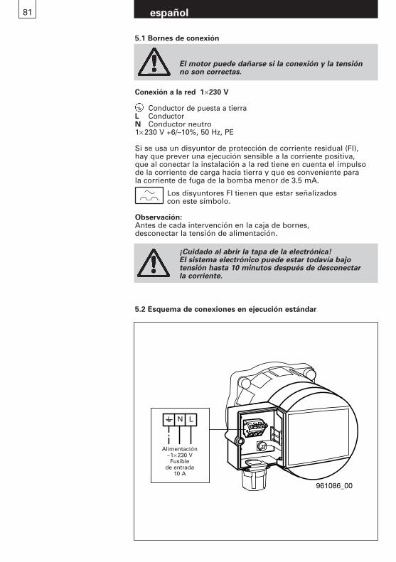
español81
Conexión a la red 1×230 V
Conductor de puesta a tierraL Conductor N Conductor neutro 1× 230 V +6/–10%, 50 Hz, PE
Si se usa un disyuntor de protección de corriente residual (FI),hay que prever una ejecución sensible a la corriente positiva,que al conectar la instalación a la red tiene en cuenta el impulsode la corriente de carga hacia tierra y que es conveniente parala corriente de fuga de la bomba menor de 3.5 mA.
Los disyuntores FI tienen que estar señalizados con este símbolo.
Observación:Antes de cada intervención en la caja de bornes, desconectar la tensión de alimentación.
5.1 Bornes de conexión
El motor puede dañarse si la conexión y la tensión no son correctas.
¡Cuidado al abrir la tapa de la electrónica!El sistema electrónico puede estar todavía bajo tensión hasta 10 minutos después de desconectar la corriente.
961086_00
N L
Speisung ~ 1x230V
Vorsicherung10A
Alimentación~1× 230 V
Fusible de entrada
10 A
5.2 Esquema de conexiones en ejecución estándar
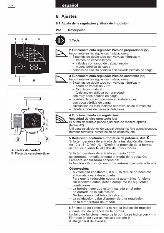
español82
6. Ajustes
6.1 Ajuste de la regulación y altura de impulsión
Pos. Descripción
A Teclas de controlB Placa de características
9610
87_0
0
B A 5 Reducción nocturna automática de potencia Aut.Si la temperatura de entrada de la instalación disminuye de 10 a 15 °C (mín. 0.1 °C/min), la potencia de la bomba se reduce a «min » al cabo de unas 2 horas.
Si la temperatura de entrada aumenta 10 °C, se conmuta inmediatamente al modo de regulación.Lámpara señalizadora encendida: la función «Reducción nocturna automática» está activada.
Observación:– A velocidad constante I, II o III, la reducción nocturna
automática está desactivada.Para que la reducción nocturna automática funcione sin inconvenientes, deben cumplirse las siguientes condiciones:
– La bomba tiene que estar instalada en el tubo de entrada de la calefacción.No funciona en el tubo de retorno.
– La calefacción debe disponer de una regulación de la temperatura del medio.
1 Tecla
2 Funcionamiento regulado: Presión proporcional (pp)Importante en las siguientes instalaciones:– Sistemas de doble tubo con válvulas térmicas y
– tramos de cañería largos– válvulas con rango de trabajo amplio– mucha pérdida de carga
– bombas de circuito primario con elevada pérdida de carga
3 Funcionamiento regulado: Presión constante (cp)Importante en las siguientes instalaciones:– Sistemas de doble tubo con válvulas térmicas y
– altura de impulsión <2m– Circulación natural
(calefacción antigua por gravedad)– con muy poca pérdida de carga– bombas del circuito primario en instalaciones
con poca pérdida de carga– calefacción de losa radiante con válvulas de termostato – Calefacciones de haces unitubulares
4 Funcionamiento sin regulación: Velocidad de giro constante (cs)El punto de trabajo puede ajustarse de manera óptima (teclas A2).Útil para instalaciones de caudal constante: Aire acondicionado,bombas térmicas, alimentación de calderas, etc.
1
5 6
2 3 4
6 En estado de conexión a la red, la indicación muestra el consumo de potencia de la bomba.Un fallo de funcionamiento de la bomba se indica con «- -».Eliminación de averías, véase apartado 9 (Lista general de averías)
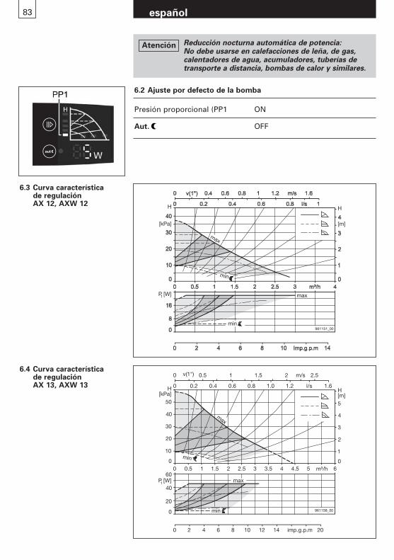
83 español
6.3 Curva característica de regulación AX 12, AXW 12
6.4 Curva característica de regulación AX 13, AXW 13
0
0 0
1
H[m]
0
20
0
0
0
10
imp.g.p.m
961158_00
max
min
min
max
20
30
40
50
2
3
4
5
H[kPa]
P [W]
0.5 1 1.5 2 2.5 3 3.5 4 4.5 5 m³/h 6
0.2 0.4 0.6 0.8 1.0 1.2 l/s 1.6
v(1") 0.5 1 1.5 2 2.5
2 4 6 8 10 12 14 20
1
40
60
m/s
H
[m]
max
H
[kPa]
P [W]1
961151_00
min
min
max
6.2 Ajuste por defecto de la bomba
Presión proporcional (PP1 ON
Aut. OFF
Reducción nocturna automática de potencia:No debe usarse en calefacciones de leña, de gas, calentadores de agua, acumuladores, tuberías de transporte a distancia, bombas de calor y similares.
Atención
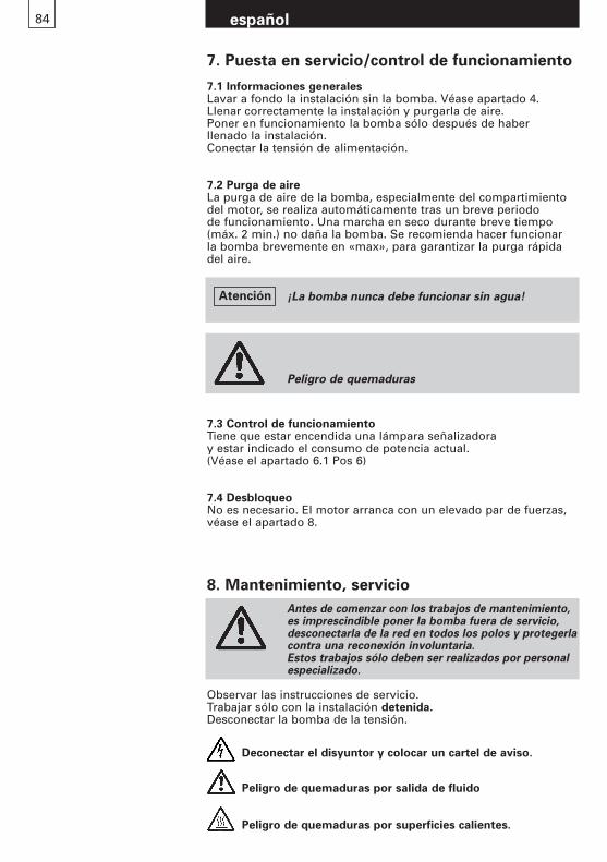
84 español
7. Puesta en servicio/control de funcionamiento
7.1 Informaciones generalesLavar a fondo la instalación sin la bomba. Véase apartado 4.Llenar correctamente la instalación y purgarla de aire.Poner en funcionamiento la bomba sólo después de haber llenado la instalación.Conectar la tensión de alimentación.
7.2 Purga de aireLa purga de aire de la bomba, especialmente del compartimientodel motor, se realiza automáticamente tras un breve periodo de funcionamiento. Una marcha en seco durante breve tiempo(máx. 2 min.) no daña la bomba. Se recomienda hacer funcionar la bomba brevemente en «max», para garantizar la purga rápidadel aire.
7.3 Control de funcionamientoTiene que estar encendida una lámpara señalizadora y estar indicado el consumo de potencia actual.(Véase el apartado 6.1 Pos 6)
7.4 DesbloqueoNo es necesario. El motor arranca con un elevado par de fuerzas,véase el apartado 8.
Peligro de quemaduras
Antes de comenzar con los trabajos de mantenimiento,es imprescindible poner la bomba fuera de servicio, desconectarla de la red en todos los polos y protegerlacontra una reconexión involuntaria.Estos trabajos sólo deben ser realizados por personal especializado.
Observar las instrucciones de servicio.Trabajar sólo con la instalación detenida.Desconectar la bomba de la tensión.
Deconectar el disyuntor y colocar un cartel de aviso.
Peligro de quemaduras por salida de fluido
Peligro de quemaduras por superficies calientes.
8. Mantenimiento, servicio
¡La bomba nunca debe funcionar sin agua!Atención
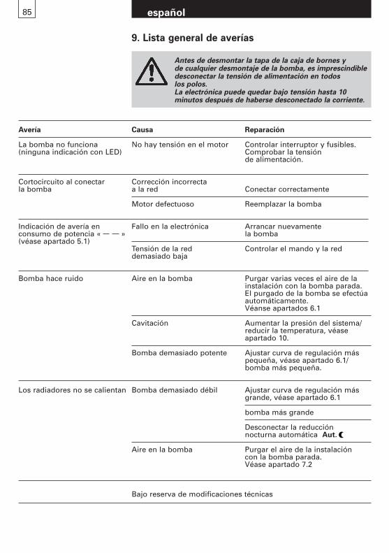
85 español
9. Lista general de averías
Antes de desmontar la tapa de la caja de bornes y de cualquier desmontaje de la bomba, es imprescindibledesconectar la tensión de alimentación en todos los polos.La electrónica puede quedar bajo tensión hasta 10 minutos después de haberse desconectado la corriente.
Avería Causa Reparación
La bomba no funciona No hay tensión en el motor Controlar interruptor y fusibles.(ninguna indicación con LED) Comprobar la tensión
de alimentación.
Cortocircuito al conectar Corrección incorrecta la bomba a la red Conectar correctamente
Motor defectuoso Reemplazar la bomba
Indicación de avería en Fallo en la electrónica Arrancar nuevamente consumo de potencia « » la bomba (véase apartado 5.1)
Tensión de la red Controlar el mando y la reddemasiado baja
Bomba hace ruido Aire en la bomba Purgar varias veces el aire de lainstalación con la bomba parada.El purgado de la bomba se efectúaautomáticamente.Véanse apartados 6.1
Cavitación Aumentar la presión del sistema/reducir la temperatura, véase apartado 10.
Bomba demasiado potente Ajustar curva de regulación máspequeña, véase apartado 6.1/bomba más pequeña.
Los radiadores no se calientan Bomba demasiado débil Ajustar curva de regulación másgrande, véase apartado 6.1
bomba más grande
Desconectar la reducción nocturna automática Aut.
Aire en la bomba Purgar el aire de la instalación con la bomba parada.Véase apartado 7.2
Bajo reserva de modificaciones técnicas
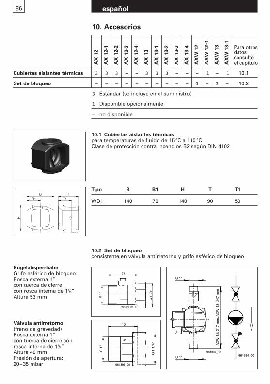
10. Accesorios
AX
12
AX
12-1
AX
12-2
AX
12-3
AX
12-4
AX
13
AX
13-1
AX
13-2
AX
13-3
AX
13-4
AX
W 1
2
AX
W 1
2-1
AX
W 1
3
AX
W 1
3-1
Para otrosdatos consulte el capítulo
Cubiertas aislantes térmicas 3 3 3 – – 3 3 3 – – – l – l 10.1
Set de bloqueo – – – – – – – – – – 3 – 3 – 10.2
3 Estándar (se incluye en el suministro)
l Disponible opcionalmente
– no disponible
Kugelabsperrhahn Grifo esférico de bloqueo Rosca externa 1” con tuerca de cierre con rosca interna de 11/4”Altura 53 mm
Válvula antirretorno (freno de gravedad)Rosca externa 1” con tuerca de cierre conrosca interna de 11/4”Altura 40 mmPresión de apertura: 20–35 mbar
961194_00
BB1 T1
T
H
10.1 Cubiertas aislantes térmicaspara temperaturas de fluido de 15 °C a 110 °CClase de protección contra incendios B2 según DIN 4102
Tipo B B1 H T T1
WD1 140 70 140 90 50
10.2 Set de bloqueoconsistente en válvula antirretorno y grifo esférico de bloqueo
86 español
G 1
"
G 1
1/4
"
40
961395_00
G 1"
G 1"961397_00
AX
W 1
2: 2
17 m
m, A
XW
13:
247
mm
G 1
"
G 1
1/4
"
53
961396_00
961394_00
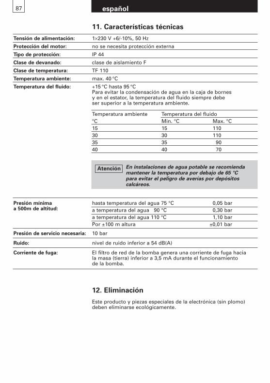
87 español
11. Características técnicas
Tensión de alimentación: 1×230 V +6/-10%, 50 Hz
Protección del motor: no se necesita protección externa
Tipo de protección: IP 44
Clase de devanado: clase de aislamiento F
Clase de temperatura: TF 110
Temperatura ambiente: max. 40 °C
Temperatura del fluido: +15 °C hasta 95 °CPara evitar la condensación de agua en la caja de bornes y en el estator, la temperatura del fluido siempre debe ser superior a la temperatura ambiente.
hasta temperatura del agua 75 °C 0,05 bara temperatura del agua 90 °C 0,30 bara temperatura del agua 110 °C 1,10 barPor ±100 m altura ±0,01 bar
Presión de servicio necesaria: 10 bar
Ruido: nivel de ruido inferior a 54 dB(A)
Corriente de fuga: El filtro de red de la bomba genera una corriente de fuga hacia la masa (tierra) inferior a 3,5 mA durante el funcionamiento de la bomba.
Presión mínimaa 500m de altitud:
Temperatura ambiente Temperatura del fluido°C Min. °C Max. °C15 15 11030 30 11035 35 9040 40 70
12. Eliminación
Este producto y piezas especiales de la electrónica (sin plomo)deben eliminarse ecológicamente.
En instalaciones de agua potable se recomienda mantener la temperatura por debajo de 65 °C para evitar el peligro de averías por depósitos calcáreos.
Atención

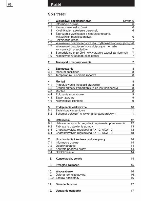
89
Spis treści
1. Wskazówki bezpieczeństwa Strona 61.1 Informacje ogólne 61.2 Zaznaczanie wskazówek 61.3 Kwalifikacje i szkolenie personelu 61.4 Zagrożenia wynikające z nieprzestrzegania
wskazówek bezpieczeństwa 61.5 Bezpieczna praca 71.7 Wskazówki bezpieczeństwa dla użytkownika/obsługującego 61.7 Wskazówki bezpieczeństwa dotyczące montażu
konserwacji i przeglądów 71.8 Samodzielne przeróbki i wytwarzanie części zamiennych 71.9 Niedozwolony sposób eksploatacji 7
2. Transport i magazynowanie 7
3. Zastosowanie 83.1 Medium zasilające 83.2 Temperatura i ciśnienie robocze 8
4. Montaż 84.1 Przepłukiwanie instalacji grzewczej 84.2 Środek przeciw zamarzaniu (o ile jest konieczny) 84.3 Montaż 84.4 Położenie montażowe 94.5 Zawór zwrotny 94.6 Najmniejsze ciśnienie 9
5. Podłączenie elektryczne 105.1 Zaciski przyłączeniowe 115.2 Schemat połączeń w wykonaniu standardowym 11
6. Ustawienie 126.1 Ustawienie sposobu regulacji i wysokości pompowania 126.2 Fabryczne ustawienie pompy 136.3 Charakterystyka regulacyjna AX 12, AXW 12 136.4 Charakterystyka regulacyjna AX 13, AXW 13 13
7. Uruchomienie i kontrola podczas pracy 147.1 Informacje ogólne 147.2 Odpowietrzanie 147.3 Kontrola podczas pracy 147.4 Odblokowanie 14
8. Konserwacja, serwis 14
9. Przegląd zakłóceń 15
10. Wyposażenie 1610.1 Osłona termoizolacyjna 1610.2 Zestaw odcinający 16
11. Dane techniczne 17
12. Usuwanie odpadów 17
Polski
90
Ten symbol ostrzega przedniebezpiecznym napięciem elektrycznym.“Znaki bezpieczeństwa wg DIN 4844-W8”
Wskazówki bezpieczeństwa zawarte w niniejszej instrukcji montażu i eksploatacji, jakie w razienieprzestrzegania mogą stanowić zagrożenie dla ludzi, są specjalnie oznaczone ogólnym symbolem zagrożenia «Symbol zagrożenia DIN 4844-W9”.
1. Wskazówki bezpieczeństwa
1.1 Informacje ogólneNiniejsza instrukcja montażu i eksploatacji zawiera podstawowewskazówki, których należy przestrzegać przy montażu, podczaspracy i konserwacji. Dlatego przed przystąpieniem do montażu i uruchomienia musi ją bezwzględnie przeczytać monter jak teżupoważniony personel i użytkownik. Instrukcja musi przez całyczas być dostępna w miejscu użytkowania urządzenia.Należy przestrzegać nie tylko ogólnych wskazówek zawartych w tym rozdziale “Wskazówki bezpieczeństwa”, ale również tych specjalnych wskazówek znajdujących się w innych rozdziałach, a odnoszących się do bezpieczeństwa.
1.2 Zaznaczanie wskazówek
Ten symbol znajduje się przy wskazówkach bezpieczeństwa, których nieprzestrzeganie może powodować zagrożenie dla maszyny i jej działania.
Uwaga
Informacje umieszczone bezpośrednio na urządzeniu, jak np.
– strzałka kierunku obrotów,– Oznaczenia przyłączy płynów
muszą być bezwzględnie przestrzegane i utrzymywane w całkowicie czytelnym stanie.
1.3 Kwalifikacje i szkolenie personeluPersonel zajmujący się montażem, obsługą, konserwacją i kontrolą musi posiadać odpowiednie kwalifikacje. Zakres odpowiedzialności, kompetencje personelu i nadzór muszą być dokładnie ustalone przez użytkownika.
1.4 Zagrożenia wynikające z nieprzestrzegania wskazówek bezpieczeństwa
Nieprzestrzeganie wskazówek bezpieczeństwa może stwarzaćzagrożenie zarówno dla osób jak też dla środowiska i urządzenia.Nieprzestrzeganie wskazówek bezpieczeństwa może prowadzić do utraty jakichkolwiek roszczeń odszkodowawczych.
Polski
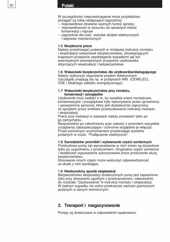
91
W szczególności nieprzestrzeganie może przykładowo pociągać za sobą następujące zagrożenia:– nieprawidłowe działanie ważnych funkcji sprzętu,– nieprawidłowości w stosunku do opisanych metod
konserwacji i napraw– zagrożenie dla ludzi wskutek działań elektrycznych
i wpływów mechanicznych
1.5 Bezpieczna pracaNależy przestrzegać podanych w niniejszej instrukcji montażu i eksploatacji wskazówek bezpieczeństwa, obowiązujących krajowych przepisów zapobiegania wypadkom jak też ewentualnych wewnętrznych przepisów użytkownika dotyczących eksploatacji i bezpieczeństwa.
1.6 Wskazówki bezpieczeństwa dla użytkownika/obsługującegoNależy wykluczyć zagrożenia prądem elektrycznym (szczegóły znajdują się np. w przepisach NIN (CENELEC), VDE i lokalnego zakładu energetycznego).
1.7 Wskazówki bezpieczeństwa przy montażu, konserwacji i przeglądów
Użytkownik musi zadbać o to, by wszelkie prace montażowe, konserwacyjne i przeglądowe były wykonywane przez uprawniony i upoważniony personel, który jest dostatecznie zapoznany ze sprzętem przez wnikliwe przestudiowanie instrukcji montażu i eksploatacji.Prace przy instalacji w zasadzie należy prowadzić tylko po jej zatrzymaniu.Bezpośrednio po zakończeniu prac założyć z powrotem wszystkieurządzenia zabezpieczające i ochronne względnie je włączyć.Przed ponownym uruchomieniem przestrzegać punktów podanych w rozdz. “Podłączenie elektryczne”.
1.8 Samodzielne przeróbki i wytwarzanie części zamiennychPrzebudowa pomp lub wprowadzenie w nich zmian są dozwolonetylko po uzgodnieniu z producentem. Oryginalne części zamienne i dodatkowe wyposażenie autoryzowane przez producenta służąbezpieczeństwu. Stosowanie innych części może wykluczyć odpowiedzialność za skutki z nich wynikające.
1.9 Niedozwolony sposób eksploatacjiBezpieczeństwo eksploatacji dostarczonych pomp jest zapewnionetylko przy stosowaniu zgodnym z przeznaczeniem, odpowiednio do rozdziału “Zastosowanie” w instrukcji montażu i eksploatacji. W żadnym wypadku nie wolno przekraczać wartości granicznychpodanych w danych technicznych.
Polski
2. Transport i magazynowanie
Pompy są dostarczane w odpowiednim opakowaniu.
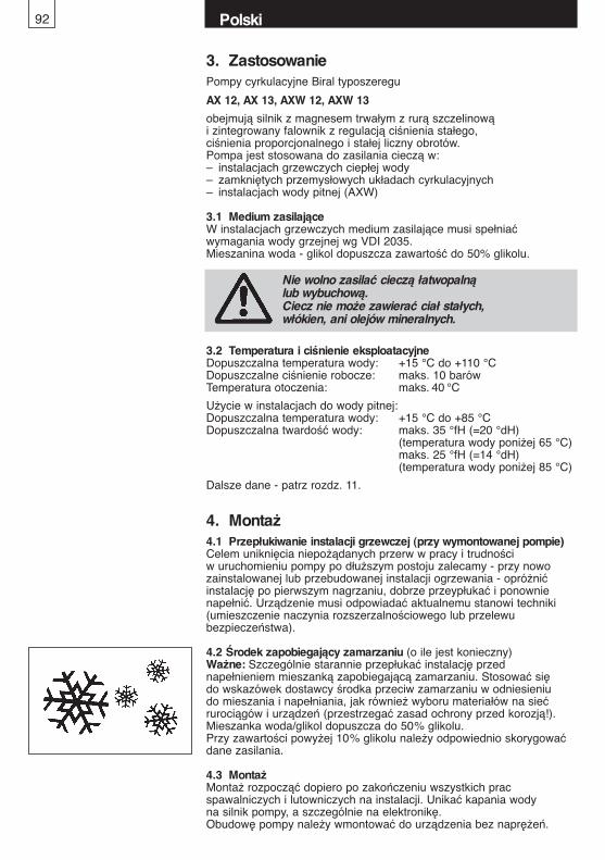
Polski92
3. ZastosowaniePompy cyrkulacyjne Biral typoszeregu
AX 12, AX 13, AXW 12, AXW 13
obejmują silnik z magnesem trwałym z rurą szczelinową i zintegrowany falownik z regulacją ciśnienia stałego, ciśnienia proporcjonalnego i stałej liczny obrotów.Pompa jest stosowana do zasilania cieczą w:– instalacjach grzewczych ciepłej wody– zamkniętych przemysłowych układach cyrkulacyjnych– instalacjach wody pitnej (AXW)
3.1 Medium zasilająceW instalacjach grzewczych medium zasilające musi spełniać wymagania wody grzejnej wg VDI 2035. Mieszanina woda - glikol dopuszcza zawartość do 50% glikolu.
4. Montaż4.1 Przepłukiwanie instalacji grzewczej (przy wymontowanej pompie)Celem uniknięcia niepożądanych przerw w pracy i trudności w uruchomieniu pompy po dłuższym postoju zalecamy - przy nowo zainstalowanej lub przebudowanej instalacji ogrzewania - opróżnićinstalację po pierwszym nagrzaniu, dobrze przeypłukać i ponownienapełnić. Urządzenie musi odpowiadać aktualnemu stanowi techniki(umieszczenie naczynia rozszerzalnościowego lub przelewubezpieczeństwa).
4.2 Środek zapobiegający zamarzaniu (o ile jest konieczny)Ważne: Szczególnie starannie przepłukać instalację przed napełnieniem mieszanką zapobiegającą zamarzaniu. Stosować się do wskazówek dostawcy środka przeciw zamarzaniu w odniesieniu do mieszania i napełniania, jak również wyboru materiałów na sieć rurociągów i urządzeń (przestrzegać zasad ochrony przed korozją!).Mieszanka woda/glikol dopuszcza do 50% glikolu.Przy zawartości powyżej 10% glikolu należy odpowiednio skorygowaćdane zasilania.
4.3 MontażMontaż rozpocząć dopiero po zakończeniu wszystkich prac spawalniczych i lutowniczych na instalacji. Unikać kapania wody na silnik pompy, a szczególnie na elektronikę. Obudowę pompy należy wmontować do urządzenia bez naprężeń.
Nie wolno zasilać cieczą łatwopalną lub wybuchową.Ciecz nie może zawierać ciał stałych, włókien, ani olejów mineralnych.
3.2 Temperatura i ciśnienie eksploatacyjneDopuszczalna temperatura wody: +15 °C do +110 °CDopuszczalne ciśnienie robocze: maks. 10 barówTemperatura otoczenia: maks. 40 °C
Użycie w instalacjach do wody pitnej:Dopuszczalna temperatura wody: +15 °C do +85 °CDopuszczalna twardość wody: maks. 35 °fH (=20 °dH)
(temperatura wody poniżej 65 °C)maks. 25 °fH (=14 °dH) (temperatura wody poniżej 85 °C)
Dalsze dane - patrz rozdz. 11.
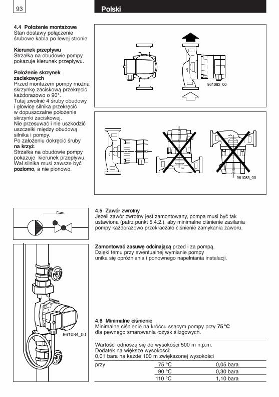
4.4 Położenie montażoweStan dostawy połączenie śrubowe kabla po lewej stronie
Kierunek przepływuStrzałka na obudowie pompypokazuje kierunek przepływu.
Położenie skrzynek zaciskowychPrzed montażem pompy możnaskrzynkę zaciskową przekręcić każdorazowo o 90°. Tutaj zwolnić 4 śruby obudowy i głowicę silnika przekręcić w dopuszczalne położenie skrzynki zaciskowej.Nie przesuwać i nie uszkodzićuszczelki między obudową silnika i pompy.Po założeniu dokręcić śrubyna krzyż.Strzałka na obudowie pompypokazuje kierunek przepływu. Wał silnika musi zawsze być poziomo, a nie pionowo.
4.5 Zawór zwrotnyJeżeli zawór zwrotny jest zamontowany, pompa musi być takustawiona (patrz punkt 5.4.2.), aby minimalne ciśnienie zasilaniapompy każdorazowo przekraczało ciśnienie zamykania zaworu.
Zamontować zasuwę odcinającą przed i za pompą.Dzięki temu przy ewentualnej wymianie pompy unika się opróżniania i ponownego napełniania instalacji.
Polski93
961082_00
961083_00
961084_00
4.6 Minimalne ciśnienieMinimalne ciśnienie na króćcu ssącym pompy przy 75°Cdla pewnego smarowania łożysk ślizgowych.
Wartości odnoszą się do wysokości 500 m n.p.m.Dodatek na większe wysokości:0,01 bara na każde 100 m zwiększonej wysokości
przy 75 °C 0,05 bara90 °C 0,30 bara
110 °C 1,10 bara
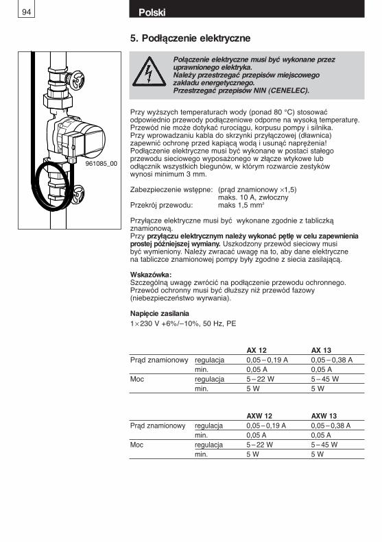
Połączenie elektryczne musi być wykonane przez uprawnionego elektryka.Należy przestrzegać przepisów miejscowego zakładu energetycznego.Przestrzegać przepisów NIN (CENELEC).
Przy wyższych temperaturach wody (ponad 80 °C) stosowaćodpowiednio przewody podłączeniowe odporne na wysoką temperaturę.Przewód nie może dotykać rurociągu, korpusu pompy i silnika.Przy wprowadzaniu kabla do skrzynki przyłączowej (dławnica)zapewnić ochronę przed kapiącą wodą i usunąć naprężenia!Podłączenie elektryczne musi być wykonane w postaci stałego przewodu sieciowego wyposażonego w złącze wtykowe lubodłącznik wszystkich biegunów, w którym rozwarcie zestykówwynosi minimum 3 mm.
Zabezpieczenie wstępne: (prąd znamionowy ×1,5) maks. 10 A, zwłoczny
Przekrój przewodu: maks 1,5 mm2
Przyłącze elektryczne musi być wykonane zgodnie z tabliczką znamionową.Przy przyłączu elektrycznym należy wykonać pętlę w celu zapewnieniaprostej późniejszej wymiany. Uszkodzony przewód sieciowy musibyć wymieniony. Należy zwracać uwagę na to, aby dane elektrycznena tabliczce znamionowej pompy były zgodne z siecia zasilającą.
Wskazówka: Szczególną uwagę zwrócić na podłączenie przewodu ochronnego.Przewód ochronny musi być dłuższy niż przewód fazowy (niebezpieczeństwo wyrwania).
Napięcie zasilania1× 230 V +6%/–10%, 50 Hz, PE
961085_00
5. Podłączenie elektryczne
AX 12 AX 13Prąd znamionowy regulacja 0,05 – 0,19 A 0,05 – 0,38 A
min. 0,05 A 0,05 AMoc regulacja 5 – 22 W 5 – 45 W
min. 5 W 5 W
AXW 12 AXW 13Prąd znamionowy regulacja 0,05 – 0,19 A 0,05 – 0,38 A
min. 0,05 A 0,05 AMoc regulacja 5 – 22 W 5 – 45 W
min. 5 W 5 W
Polski94
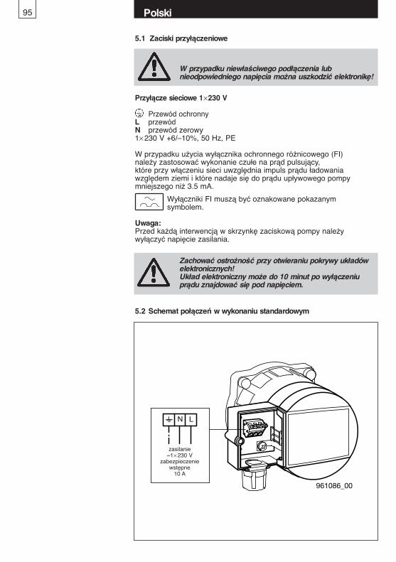
961086_00
N L
Speisung ~ 1x230V
Vorsicherung10A
5.2 Schemat połączeń w wykonaniu standardowym
zasilanie~1× 230 V
zabezpieczeniewstępne
10 A
Przyłącze sieciowe 1×230 V
Przewód ochronnyL przewódN przewód zerowy1× 230 V +6/–10%, 50 Hz, PE
W przypadku użycia wyłącznika ochronnego różnicowego (FI) należy zastosować wykonanie czułe na prąd pulsujący, które przy włączeniu sieci uwzględnia impuls prądu ładowania względem ziemi i które nadaje się do prądu upływowego pompy mniejszego niż 3.5 mA.
Wyłączniki FI muszą być oznakowane pokazanym symbolem.
Uwaga:Przed każdą interwencją w skrzynkę zaciskową pompy należy wyłączyć napięcie zasilania.
W przypadku niewłaściwego podłączenia lub nieodpowiedniego napięcia można uszkodzić elektronikę!
5.1 Zaciski przyłączeniowe
Polski95
Zachować ostrożność przy otwieraniu pokrywy układówelektronicznych!Układ elektroniczny może do 10 minut po wyłączeniuprądu znajdować się pod napięciem.
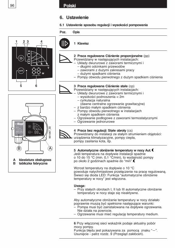
96 Polski
6. Ustawienie
6.1 Ustawienie sposobu regulacji i wysokości pompowania
Poz. Opis
A klawiatura obsługowaB tabliczka fabryczna
9610
87_0
0
B A 5 Automatyczne obniżenie temperatury w nocy Aut.Jeśli temperatura na dopływie instalacjii spadnieo 10 do 15 °C (min. 0,1 °C/min), to wydajność pompypo około 2 godzinach spadnie do “min”.
Wzrost temperatury na dopływie o 10 °Cpowoduje natychmiastowe przełączenie na pracę regulowaną.Świeci się dioda LED: Funkcja “automatyczne obniżenietemperatury w nocy” jest włączona.
Uwaga:– Przy stałych obrotach I, II lub III automatyczne obniżanie
temperatury w nocy staje się nieaktywne.
Aby automatyczne obniżanie temperatury w nocy działałopoprawnie muszą być spełnione następujące warunki:– Pompa musi być zainstalowana na dopływie ogrzewania.
Nie działa na powrocie.– Ogrzewanie musi mieć regulację temperatury medium.
1 Klawisz
2 Praca regulowana Ciśnienie proporcjonalne (pp)Przewidziany w następujących instalacjach:– Układy dwururowe z zaworami termicznymi i
– długimi odcinkami przewodów– zaworami z dużymi zakresami pracy– dużymi spadkami ciśnienia
– Pompy obwodu pierwotnego z dużym spadkiem ciśnienia
3 Praca regulowana Ciśnienie stałe (cp)Przewidziany w następujących instalacjach:– Układy dwururowe z zaworami termicznymi i
– wysokości podnoszenia < 2m– cyrkulacja naturalna
(dawne centralne ogrzewanie grawitacyjne)– z bardzo małym spadkiem ciśnienia– Pompy obwodu pierwotnego w instalacjach
z małym spadkiem ciśnienia– Ogrzewanie podłogowe z zaworami termostatycznymi – Ogrzewanie jednorurowe
4 Praca bez regulacji: Stałe obroty (cs)Przewidziany do instalacji ze stałym strumieniem objętości:urządzenia klimatyzacyjne, pompy ciepla, pompy zasilania kota, itp.
1
5 6
2 3 4
6 Przy włączonej sieci wskaźnik podaje aktualny pobór mocy pompy.Funkcja błędu jest pokazywana za pomocą znaku “—”.Usunięcie - patrz rozdz. 9 (Przegląd zakłóceń).

6.3 Charakterystyka regulacjiAX 12, AXW 12
97 Polski
6.4 Charakterystyka regulacjiAX 13, AXW 13
0
0 0
1
H[m]
0
20
0
0
0
10
imp.g.p.m
961158_00
max
min
min
max
20
30
40
50
2
3
4
5
H[kPa]
P [W]
0.5 1 1.5 2 2.5 3 3.5 4 4.5 5 m³/h 6
0.2 0.4 0.6 0.8 1.0 1.2 l/s 1.6
v(1") 0.5 1 1.5 2 2.5
2 4 6 8 10 12 14 20
1
40
60
m/s
H
[m]
max
H
[kPa]
P [W]1
961151_00
min
min
max
6.2 Fabryczne ustawienie pompy
Ciśnienie proporcjonalne (PP1) WŁ
Aut. WYŁ
Nie włączać automatycznego obniżania temperaturyw nocy przy ogrzewaniu drewnem i gazem, przy podgrzewaczach wody, ładowaniu akumulatorów, liniach przesyłowych, pompach ciepła i podobnych.
Uwaga
Polski98
7. Uruchomienie/kontrola w czasie pracy
7.1 Informacje ogólne Dokładnie wypłukać instalację bez pompy. Patrz rozdział 4.Urządzenie odpowiednio napełnić i odpowietrzyć.Pompę uruchamiać tylko przy napełnionym urządzeniu.Włączyć napięcie zasilania.
7.2 OdpowietrzanieOdpowietrzanie pompy, a szczególnie komory silnika, przebiega samoczynnie, po krótkim okresie pracy. Krótkotrwały (maks. 2 min.) bieg na sucho nie szkodzi pompie.Zaleca się pozostawić pompę na krótki okres na pracę na “max”, aby zapewnić szybkie odpowietrzenie.
7.3 Kontrola podczas pracyZawsze musi palić się LED i musi być pokazywany aktualny pobór mocy. (patrz rozdział 6.1, poz.6)
7.4 OdblokowanieNie jest konieczne. Silnik uruchamia się z wysokim momencierozruchowym i dysponuje wewnętrznym programem odblokowującym.
Niebezpieczeństwo poparzenia
Przed rozpoczęciem konserwacji koniecznie wyłączyćpompę, wszystkie bieguny odłączyć od sieci i zabezpieczyć przed ponownym włączeniem. Wykonanie powierzyć tylko upoważnionemu personelowi.
Przestrzegać instrukcji obsługi. Prace prowadzić wyłącznie przy zatrzymanym urządzeniu.Odłączyć pompę od napięcia.
Wyjąć bezpiecznik i umieścić tablicę ostrzegawczą.
Groźba poparzenia występującymi mediami.
Zagrożenie pożarem od gorących powierzchni.
8. Konserwacja, serwis
Pompa nie może pracować bez wody!Uwaga
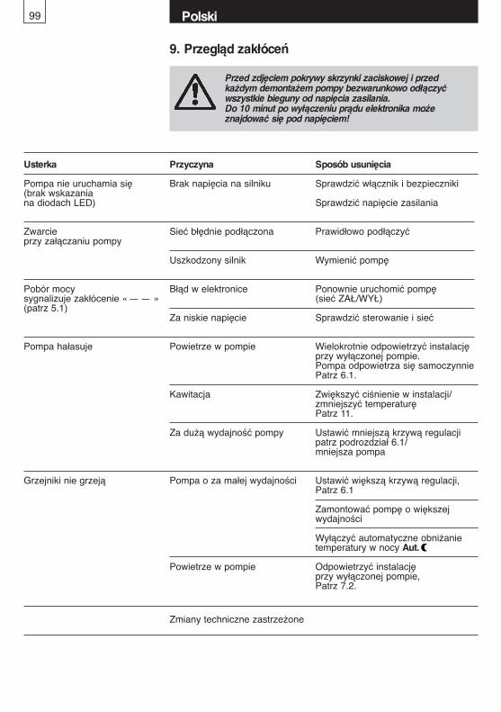
Polski99
9. Przegląd zakłóceń
Przed zdjęciem pokrywy skrzynki zaciskowej i przedkażdym demontażem pompy bezwarunkowo odłączyćwszystkie bieguny od napięcia zasilania.Do 10 minut po wyłączeniu prądu elektronika może znajdować się pod napięciem!
Usterka Przyczyna Sposób usunięcia
Pompa nie uruchamia się Brak napięcia na silniku Sprawdzić włącznik i bezpieczniki(brak wskazania na diodach LED) Sprawdzić napięcie zasilania
Zwarcie Sieć błędnie podłączona Prawidłowo podłączyćprzy załączaniu pompy
Uszkodzony silnik Wymienić pompę
Pobór mocy Błąd w elektronice Ponownie uruchomić pompę sygnalizuje zakłócenie « » (sieć ZAŁ/WYŁ) (patrz 5.1)
Za niskie napięcie Sprawdzić sterowanie i sieć
Pompa hałasuje Powietrze w pompie Wielokrotnie odpowietrzyć instalację przy wyłączonej pompie. Pompa odpowietrza się samoczynniePatrz 6.1.
Kawitacja Zwiększyć ciśnienie w instalacji/zmniejszyć temperaturęPatrz 11.
Za dużą wydajność pompy Ustawić mniejszą krzywą regulacjipatrz podrozdział 6.1/mniejsza pompa
Grzejniki nie grzeją Pompa o za małej wydajności Ustawić większą krzywą regulacji,Patrz 6.1
Zamontować pompę o większej wydajności
Wyłączyć automatyczne obniżanie temperatury w nocy Aut.
Powietrze w pompie Odpowietrzyć instalację przy wyłączonej pompie, Patrz 7.2.
Zmiany techniczne zastrzeżone
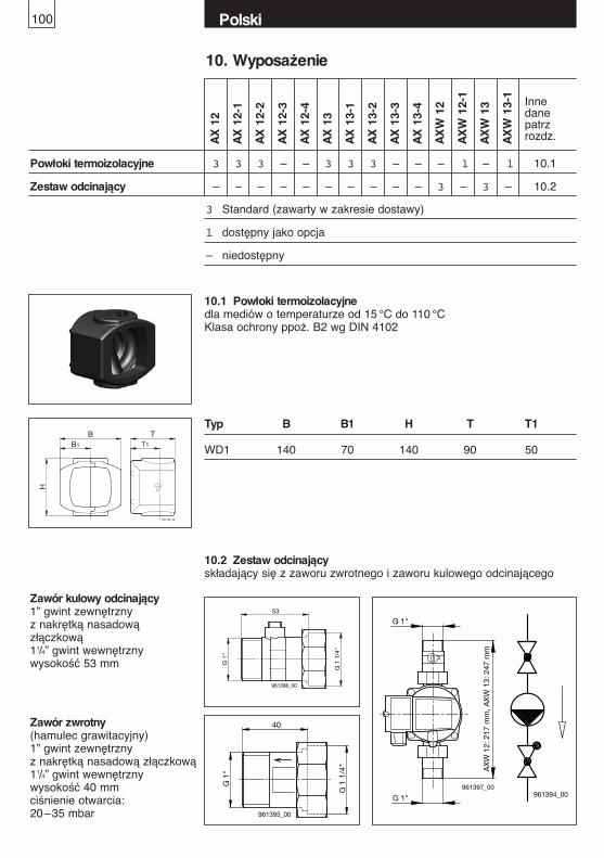
Polski100
10. Wyposażenie
AX
12
AX
12-
1
AX
12-
2
AX
12-
3
AX
12-
4
AX
13
AX
13-
1
AX
13-
2
AX
13-
3
AX
13-
4
AX
W 1
2
AX
W 1
2-1
AX
W 1
3
AX
W 1
3-1
Innedanepatrzrozdz.
Powłoki termoizolacyjne 3 3 3 – – 3 3 3 – – – l – l 10.1
Zestaw odcinający – – – – – – – – – – 3 – 3 – 10.2
3 Standard (zawarty w zakresie dostawy)
l dostępny jako opcja
– niedostępny
G 1
"
G 1
1/4
"
40
961395_00
G 1"
G 1"961397_00
AX
W 1
2: 2
17 m
m, A
XW
13:
247
mm
Zawór kulowy odcinający 1” gwint zewnętrzny z nakrętką nasadowązłączkową 11/4” gwint wewnętrznywysokość 53 mm G
1"
G 1
1/4
"
53
961396_00
Zawór zwrotny (hamulec grawitacyjny)1” gwint zewnętrzny z nakrętką nasadową złączkową 11/4” gwint wewnętrznywysokość 40 mmciśnienie otwarcia: 20–35 mbar
961194_00
BB1 T1
T
H
10.1 Powłoki termoizolacyjnedla mediów o temperaturze od 15 °C do 110 °CKlasa ochrony ppoż. B2 wg DIN 4102
Typ B B1 H T T1
WD1 140 70 140 90 50
10.2 Zestaw odcinającyskładający się z zaworu zwrotnego i zaworu kulowego odcinającego
961394_00
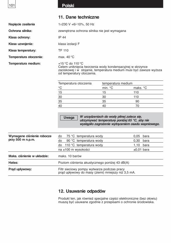
11. Dane techniczne
Napięcie zasilania 1×230 V +6/-10%, 50 Hz
Ochrona silnika: zewnętrzna ochrona silnika nie jest wymagana
Klasa ochrony: IP 44
Klasa uzwojenia: klasa izolacji F
Klasa temperatury: TF 110
Temperatura otoczenia: max. 40 °C
Temperatura medium: +15 °C do 110 °CCelem uniknięcia tworzenia wody kondensacyjnej w skrzynce zaciskowej i w stojanie, temperatura medium musi być zawsze wyższa od temperatury otoczenia.
do 75 °C temperatura wody 0,05 barado 90 °C temperatura wody 0,30 barado 110 °C temperatura wody 1,10 barana ±100 m wysokości ±0,01 bara
Maks. ciśnienie w układzie: maks. 10 barów
Hałas: Poziom ciśnienia akustycznego poniżej 43 dB(A)
Prąd upływowy: Filtr sieciowy pompy wytwarza podczas pracy prąd upływowy do masy (ziemi) mniejszy niż 3,5 mA.
Wymagane ciśnienie roboczeprzy 500 m n.p.m.
Temperatura otoczenia temperatura medium°C min. °C maks. °C15 15 11030 30 11035 35 9040 40 70
W urządzeniach do wody pitnej zaleca się, utrzymywać temperaturę poniżej 65 °C, aby nie wystąpiło zagrożenie wytrąceniem osadu wapniowego.
Uwaga
12. Usuwanie odpadów
Produkt ten, jak również specjalne części elektroniczne (bez ołowiu)muszą być usuwane zgodnie z przepisami o ochronie środowiska.
Polski101


Biral AG Münsingen, Hauptsitz Schweiz
Biral AGSüdstrasse 10CH-3110 MünsingenTel. +41(0) 31 720 90 00Fax +41(0) 31 720 94 42E-Mail: [email protected]
Generalvertreter Schweiz:Hoval Herzog AGCH-8706 FeldmeilenTel. +41(0)44 925 61 11Fax +41(0)44 923 11 39
Biral GmbHPräzisionspumpenFreiherr-vom-Stein-Weg 15D-72108 Rottenburg am NeckarTel. +49 (0) 7472 16 33 0Fax +49 (0) 7472 16 34 0E-Mail: [email protected]
Biral Pompen B.V.Printerweg 13 3821 APPostbus 2650 3800 GENL-AmersfoortTel. +31(0) 33 455 94 44Fax +31(0) 33 455 96 10E-Mail: [email protected]
09/1
1 0
8 03
78.2
011_
05 -
Prin
ted
in S
witz
erla
nd