Embed Size (px)
Citation preview
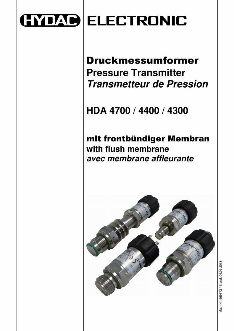
Druckmessumformer
Pressure Transmitter Transmetteur de Pression
HDA 4700 / 4400 / 4300
mit frontbündiger Membran
with flush membrane avec membrane affleurante
Mat
–N
r. 6
6987
2 / S
tand
: 04.
09.2
013
2 HDA 4700 / 4400 / 4300 mit frontbündiger Membran
Stand: 04.09.2013 HYDAC ELECTRONIC GMBH Mat. Nr.: 669872
D
HDA 4700 / 4400 / 4300 mit frontbündiger Membran 3
Stand: 04.09.2013 HYDAC ELECTRONIC GMBH Mat. Nr.: 669872
D
Inhalt
1 Allgemeines __________________________________________ 5
2 Sicherheitshinweise ____________________________________ 5
3 Montage _____________________________________________ 6
4 Technische Daten _____________________________________ 7
5 Typenschlüssel _______________________________________ 8
6 Anschlussbelegung ____________________________________ 9
7 Geräteabmessungen __________________________________ 10
8 Zubehör _____________________________________________ 11
4 HDA 4700 / 4400 / 4300 mit frontbündiger Membran
Stand: 04.09.2013 HYDAC ELECTRONIC GMBH Mat. Nr.: 669872
D
Vorwort
Für Sie, den Benutzer unseres Produktes, haben wir in dieser Dokumentation die wichtigsten Hinweise zum Bedienen und Warten zusammengestellt. Sie dient Ihnen dazu, das Produkt kennen zu lernen und seine bestimmungsgemäßen Einsatzmöglichkeiten optimal zu nutzen. Diese Dokumentation muss ständig am Einsatzort verfügbar sein. Bitte beachten Sie, dass die in dieser Dokumentation gemachten Angaben der Gerätetechnik zu dem Zeitpunkt der Literaturerstellung entsprechen. Abweichungen bei technischen Angaben, Abbildungen und Maßen sind deshalb möglich. Entdecken Sie beim Lesen dieser Dokumentation Fehler oder haben weitere Anregungen und Hinweise, so wenden Sie sich bitte an: HYDAC ELECTRONIC GMBH Technische Dokumentation Hauptstraße 27 66128 Saarbrücken -Deutschland- Tel: +49(0)6897 / 509-01 Fax: +49(0)6897 / 509-1726 Email: [email protected] Die Redaktion freut sich über Ihre Mitarbeit. „Aus der Praxis für die Praxis“
HDA 4700 / 4400 / 4300 mit frontbündiger Membran 5
Stand: 04.09.2013 HYDAC ELECTRONIC GMBH Mat. Nr.: 669872
D
1 Allgemeines Die Druckmessumformer HDA 4000 mit frontbündiger Membran wurden speziell für Applikationen entwickelt, in denen die verwendeten Medien zu einem Verstopfen, Verkleben oder Einfrieren eines Standard-Druckanschlusses führen könnten. Weitere Anwendungsfelder finden sich in Prozessen mit wechselnden Medien, in denen Rückstände zu Vermischung oder Verunreinigung der Medien führen könnte. Der Druckanschluss ist frontseitig durch eine voll verschweißte Edelstahlmembran bündig abgeschlossen und intern mit einer Druckmittlerflüssigkeit gefüllt, welche den Prozessdruck hydrostatisch zur Messzelle überträgt. Falls Sie Fragen bezüglich der technischen Daten oder Eignung für Ihre Anwendungen haben, wenden Sie sich bitte an unseren technischen Vertrieb. Die Druckmessumformer der Serie HDA 4000 werden einzeln auf einem rechnergesteuerten Prüfplatz abgeglichen und einem Endtest unterzogen. Sie sind wartungsfrei und sollten beim Einsatz innerhalb der Spezifikationen (siehe Technische Daten) einwandfrei arbeiten. Falls trotzdem Fehler auftreten sollten, wenden Sie sich bitte an den HYDAC–Service. Fremdeingriffe in das Gerät führen zum Erlöschen jeglicher Gewährleistungsansprüche.
2 Sicherheitshinweise Überprüfen Sie vor der Inbetriebnahme den Zustand des Gerätes sowie des mitgelieferten Zubehörs. Lesen Sie vor der Inbetriebnahme des Gerätes die Bedienanleitung und stellen Sie sicher, dass das Gerät für Ihre Anwendung geeignet ist. Falsche Handhabung bzw. die Nichteinhaltung von Gebrauchshinweisen oder technischen Angaben kann zu Sach- und / oder Personenschäden führen. Es ist unbedingt auf die Verträglichkeit der Messmedien mit den verwendeten Werkstoffen des Druckschalters zu achten; ebenso sind die Überlast- und Berstdrücke einzuhalten
6 HDA 4700 / 4400 / 4300 mit frontbündiger Membran
Stand: 04.09.2013 HYDAC ELECTRONIC GMBH Mat. Nr.: 669872
D
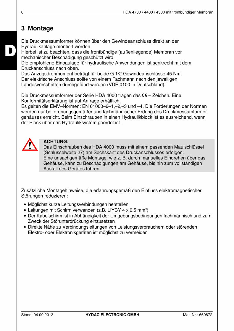
3 Montage Die Druckmessumformer können über den Gewindeanschluss direkt an der Hydraulikanlage montiert werden. Hierbei ist zu beachten, dass die frontbündige (außenliegende) Membran vor mechanischer Beschädigung geschützt wird. Die empfohlene Einbaulage für hydraulische Anwendungen ist senkrecht mit dem Druckanschluss nach oben. Das Anzugsdrehmoment beträgt für beide G 1/2 Gewindeanschlüsse 45 Nm. Der elektrische Anschluss sollte von einem Fachmann nach den jeweiligen Landesvorschriften durchgeführt werden (VDE 0100 in Deutschland). Die Druckmessumformer der Serie HDA 4000 tragen das – Zeichen. Eine Konformitätserklärung ist auf Anfrage erhältlich. Es gelten die EMV–Normen: EN 61000–6–1,–2,–3 und –4. Die Forderungen der Normen werden nur bei ordnungsgemäßer und fachmännischer Erdung des Druckmessumformer-gehäuses erreicht. Beim Einschrauben in einen Hydraulikblock ist es ausreichend, wenn der Block über das Hydrauliksystem geerdet ist.
ACHTUNG: Das Einschrauben des HDA 4000 muss mit einem passenden Maulschlüssel (Schlüsselweite 27) am Sechskant des Druckanschlusses erfolgen. Eine unsachgemäße Montage, wie z. B. durch manuelles Eindrehen über das Gehäuse, kann zu Beschädigungen am Gehäuse, bis hin zum vollständigen Ausfall des Gerätes führen.
Zusätzliche Montagehinweise, die erfahrungsgemäß den Einfluss elektromagnetischer Störungen reduzieren:
• Möglichst kurze Leitungsverbindungen herstellen • Leitungen mit Schirm verwenden (z.B. LIYCY 4 x 0,5 mm²) • Der Kabelschirm ist in Abhängigkeit der Umgebungsbedingungen fachmännisch und zum
Zweck der Störunterdrückung einzusetzen • Direkte Nähe zu Verbindungsleitungen von Leistungsverbrauchern oder störenden
Elektro- oder Elektronikgeräten ist möglichst zu vermeiden
HDA 4700 / 4400 / 4300 mit frontbündiger Membran 7
Stand: 04.09.2013 HYDAC ELECTRONIC GMBH Mat. Nr.: 669872
D
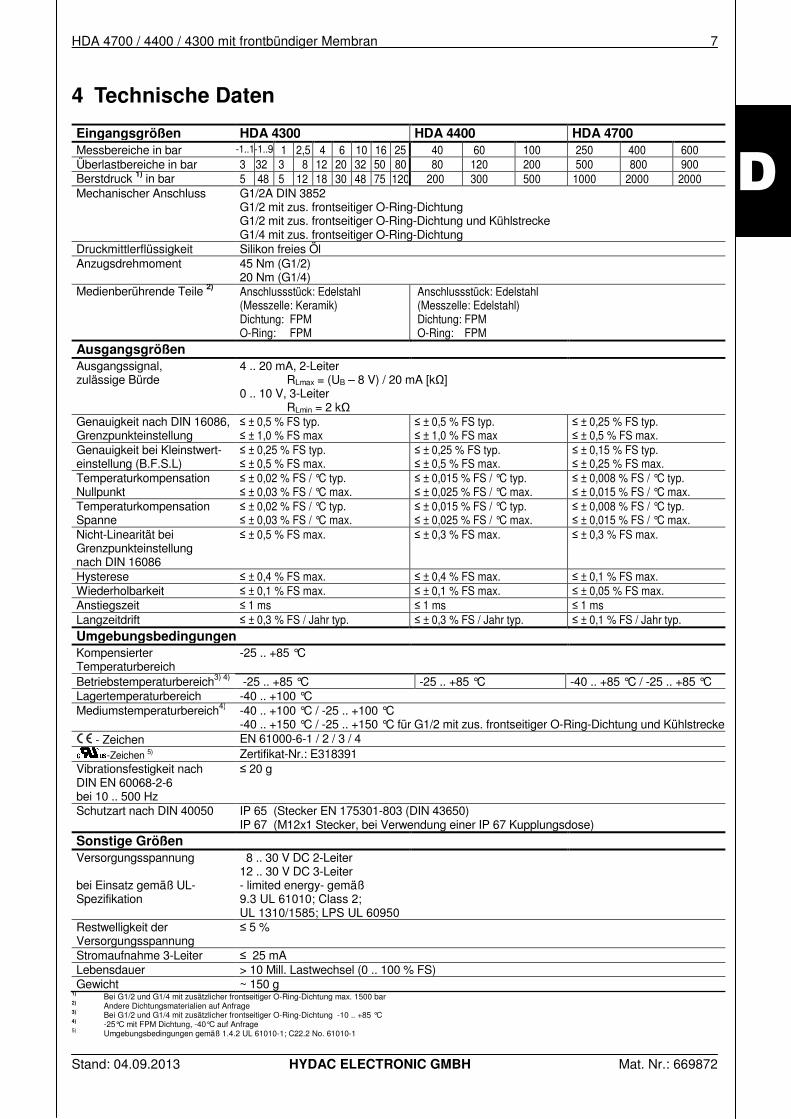
4 Technische Daten
Eingangsgrößen HDA 4300 HDA 4400 HDA 4700
Messbereiche in bar -1..1 -1..9 1 2,5 4 6 10 16 25 40 60 100 250 400 600 Überlastbereiche in bar 3 32 3 8 12 20 32 50 80 80 120 200 500 800 900 Berstdruck 1) in bar 5 48 5 12 18 30 48 75 120 200 300 500 1000 2000 2000 Mechanischer Anschluss G1/2A DIN 3852
G1/2 mit zus. frontseitiger O-Ring-Dichtung G1/2 mit zus. frontseitiger O-Ring-Dichtung und Kühlstrecke G1/4 mit zus. frontseitiger O-Ring-Dichtung
Druckmittlerflüssigkeit Silikon freies Öl Anzugsdrehmoment 45 Nm (G1/2)
20 Nm (G1/4) Medienberührende Teile 2) Anschlussstück: Edelstahl
(Messzelle: Keramik) Dichtung: FPM O-Ring: FPM
Anschlussstück: Edelstahl (Messzelle: Edelstahl) Dichtung: FPM O-Ring: FPM
Ausgangsgrößen
Ausgangssignal, zulässige Bürde
4 .. 20 mA, 2-Leiter RLmax = (UB – 8 V) / 20 mA [kΩ] 0 .. 10 V, 3-Leiter RLmin = 2 kΩ
Genauigkeit nach DIN 16086, Grenzpunkteinstellung
≤ ± 0,5 % FS typ. ≤ ± 1,0 % FS max
≤ ± 0,5 % FS typ. ≤ ± 1,0 % FS max
≤ ± 0,25 % FS typ. ≤ ± 0,5 % FS max.
Genauigkeit bei Kleinstwert-einstellung (B.F.S.L)
≤ ± 0,25 % FS typ. ≤ ± 0,5 % FS max.
≤ ± 0,25 % FS typ. ≤ ± 0,5 % FS max.
≤ ± 0,15 % FS typ. ≤ ± 0,25 % FS max.
Temperaturkompensation Nullpunkt
≤ ± 0,02 % FS / °C typ. ≤ ± 0,03 % FS / °C max.
≤ ± 0,015 % FS / °C typ. ≤ ± 0,025 % FS / °C max.
≤ ± 0,008 % FS / °C typ. ≤ ± 0,015 % FS / °C max.
Temperaturkompensation Spanne
≤ ± 0,02 % FS / °C typ. ≤ ± 0,03 % FS / °C max.
≤ ± 0,015 % FS / °C typ. ≤ ± 0,025 % FS / °C max.
≤ ± 0,008 % FS / °C typ. ≤ ± 0,015 % FS / °C max.
Nicht-Linearität bei Grenzpunkteinstellung nach DIN 16086
≤ ± 0,5 % FS max. ≤ ± 0,3 % FS max. ≤ ± 0,3 % FS max.
Hysterese ≤ ± 0,4 % FS max. ≤ ± 0,4 % FS max. ≤ ± 0,1 % FS max. Wiederholbarkeit ≤ ± 0,1 % FS max. ≤ ± 0,1 % FS max. ≤ ± 0,05 % FS max. Anstiegszeit ≤ 1 ms ≤ 1 ms ≤ 1 ms Langzeitdrift ≤ ± 0,3 % FS / Jahr typ. ≤ ± 0,3 % FS / Jahr typ. ≤ ± 0,1 % FS / Jahr typ. Umgebungsbedingungen Kompensierter Temperaturbereich
-25 .. +85 °C
Betriebstemperaturbereich3) 4) -25 .. +85 °C -25 .. +85 °C -40 .. +85 °C / -25 .. +85 °C Lagertemperaturbereich -40 .. +100 °C Mediumstemperaturbereich4) -40 .. +100 °C / -25 .. +100 °C
-40 .. +150 °C / -25 .. +150 °C für G1/2 mit zus. frontseitiger O-Ring-Dichtung und Kühlstrecke - Zeichen EN 61000-6-1 / 2 / 3 / 4
-Zeichen 5) Zertifikat-Nr.: E318391 Vibrationsfestigkeit nach DIN EN 60068-2-6 bei 10 .. 500 Hz
≤ 20 g
Schutzart nach DIN 40050 IP 65 (Stecker EN 175301-803 (DIN 43650) IP 67 (M12x1 Stecker, bei Verwendung einer IP 67 Kupplungsdose)
Sonstige Größen
Versorgungsspannung bei Einsatz gemäß UL-Spezifikation
8 .. 30 V DC 2-Leiter 12 .. 30 V DC 3-Leiter - limited energy- gemäß 9.3 UL 61010; Class 2; UL 1310/1585; LPS UL 60950
Restwelligkeit der Versorgungsspannung
≤ 5 %
Stromaufnahme 3-Leiter ≤ 25 mA Lebensdauer > 10 Mill. Lastwechsel (0 .. 100 % FS) Gewicht ~ 150 g
1) Bei G1/2 und G1/4 mit zusätzlicher frontseitiger O-Ring-Dichtung max. 1500 bar 2) Andere Dichtungsmaterialien auf Anfrage 3) Bei G1/2 und G1/4 mit zusätzlicher frontseitiger O-Ring-Dichtung -10 .. +85 °C 4)
-25°C mit FPM Dichtung, -40°C auf Anfrage 5) Umgebungsbedingungen gemäß 1.4.2 UL 61010-1; C22.2 No. 61010-1
8 HDA 4700 / 4400 / 4300 mit frontbündiger Membran
Stand: 04.09.2013 HYDAC ELECTRONIC GMBH Mat. Nr.: 669872
D
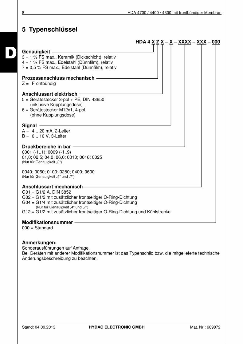
5 Typenschlüssel
HDA 4 X Z X – X – XXXX – XXX – 000
Genauigkeit 3 = 1 % FS max., Keramik (Dickschicht), relativ 4 = 1 % FS max., Edelstahl (Dünnfilm), relativ 7 = 0,5 % FS max., Edelstahl (Dünnfilm), relativ Prozessanschluss mechanisch Z = Frontbündig Anschlussart elektrisch 5 = Gerätestecker 3-pol + PE, DIN 43650 (inklusive Kupplungsdose) 6 = Gerätestecker M12x1, 4-pol.
(ohne Kupplungsdose) Signal A = 4 .. 20 mA, 2-Leiter B = 0 .. 10 V, 3-Leiter Druckbereiche in bar 0001 (-1..1); 0009 (-1..9) 01,0; 02,5; 04,0; 06,0; 0010; 0016; 0025 (Nur für Genauigkeit „3“) 0040; 0060; 0100; 0250; 0400; 0600 (Nur für Genauigkeit „4“ und „7“) Anschlussart mechanisch G01 = G1/2 A, DIN 3852 G02 = G1/2 mit zusätzlicher frontseitiger O-Ring-Dichtung G04 = G1/4 mit zusätzlicher frontseitiger O-Ring-Dichtung (Nur für Genauigkeit „4“ und „7“) G12 = G1/2 mit zusätzlicher frontseitiger O-Ring-Dichtung und Kühlstrecke Modifikationsnummer 000 = Standard Anmerkungen: Sonderausführungen auf Anfrage. Bei Geräten mit anderer Modifikationsnummer ist das Typenschild bzw. die mitgelieferte technische Änderungsbeschreibung zu beachten.
HDA 4700 / 4400 / 4300 mit frontbündiger Membran 9
Stand: 04.09.2013 HYDAC ELECTRONIC GMBH Mat. Nr.: 669872
D
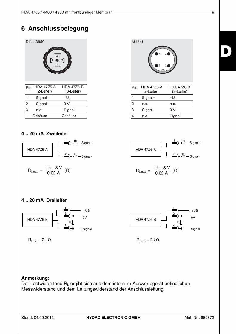
6 Anschlussbelegung
4 .. 20 mA Zweileiter
4 .. 20 mA Dreileiter
RLmin = 2 kΩ
RLmin = 2 kΩ
Anmerkung: Der Lastwiderstand RL ergibt sich aus dem intern im Auswertegerät befindlichen Messwiderstand und dem Leitungswiderstand der Anschlussleitung.
RLmax. = UB - 8 V
[Ω] 0,02 A
RLmax. = UB - 8 V
[Ω] 0,02 A
HDA 47Z5-A HDA 47Z5-B (2-Leiter) (3-Leiter)
HDA 47Z6-A HDA 47Z6-B (2-Leiter) (3-Leiter)
HDA 47Z6-A
RL
RL
Signal + 1
Signal - 3
HDA 47Z6-B
+UB
0V
Signal
RL
1
3
4
HDA 47Z5-A
RL
RL
Signal + 1
Signal - 2
HDA 47Z5-B
+UB
0V
Signal
RL
1
2
3
Gehäuse Gehäuse
10 HDA 4700 / 4400 / 4300 mit frontbündiger Membran
Stand: 04.09.2013 HYDAC ELECTRONIC GMBH Mat. Nr.: 669872
D
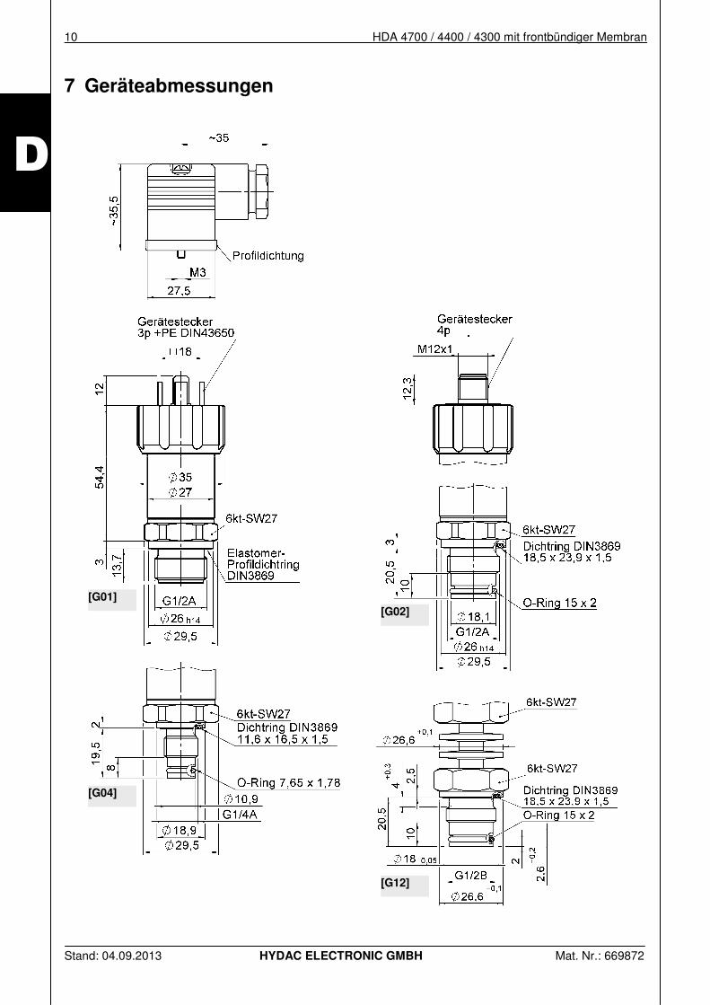
7 Geräteabmessungen
[G01]
[G02]
[G04]
[G12]
HDA 4700 / 4400 / 4300 mit frontbündiger Membran 11
Stand: 04.09.2013 HYDAC ELECTRONIC GMBH Mat. Nr.: 669872
D
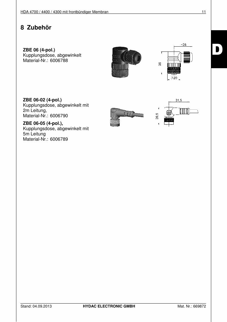
8 Zubehör
ZBE 06 (4-pol.) Kupplungsdose, abgewinkelt Material-Nr.: 6006788
ZBE 06-02 (4-pol.) Kupplungsdose, abgewinkelt mit 2m Leitung, Material-Nr.: 6006790
ZBE 06-05 (4-pol.), Kupplungsdose, abgewinkelt mit 5m Leitung Material-Nr.: 6006789
12 HDA 4700 / 4400 / 4300 mit frontbündiger Membran
Stand: 04.09.2013 HYDAC ELECTRONIC GMBH Mat. Nr.: 669872
D
HYDAC ELECTRONIC GMBH Hauptstr. 27 D-66128 Saarbrücken Germany Web: www.hydac.com E-Mail: [email protected] Tel.: +49 (0)6897 509-01 Fax.: +49 (0)6897 509-1726
HYDAC Service Für Fragen zu Reparaturen steht Ihnen der HYDAC Service zur Verfügung.
HYDAC SERVICE GMBH Hauptstr. 27 D-66128 Saarbrücken Germany Tel.: +49 (0)6897 509-1936 Fax.: +49 (0)6897 509-1933
Anmerkung
Die Angaben in dieser Bedienungsanleitung beziehen sich auf die beschriebenen Betriebsbedingungen und Einsatzfälle. Bei abweichenden Einsatzfällen und/oder Betriebsbedingungen wenden Sie sich bitte an die entsprechende Fachabteilung. Bei technischen Fragen, Hinweisen oder Störungen nehmen Sie bitte Kontakt mit Ihrer HYDAC-Vertretung auf. Technische Änderungen sind vorbehalten.
Pressure Transducer
HDA 4700 / 4400 / 4300
with flush membrane
Par
t no
. 66
9872
/ S
tatu
s 04
.09.
2013
2 HDA 4700 / 4400 / 4300 with flush membrane
Status 04.09.2013 HYDAC ELECTRONIC GMBH Part no.: 669872
E
HDA 4700 / 4400 / 4300 with flush membrane 3
Status 04.09.2013 HYDAC ELECTRONIC GMBH Part no.: 669872
E
Contents
1 General ______________________________________________ 5
2 Safety Instructions _____________________________________ 5
3 Installation ___________________________________________ 6
4 Technical data ________________________________________ 7
5 Model Code ___________________________________________ 8
6 Pin assignment ________________________________________ 9
7 Dimensions __________________________________________ 10
8 Accessoires _________________________________________ 11
4 HDA 4700 / 4400 / 4300 with flush membrane
Status 04.09.2013 HYDAC ELECTRONIC GMBH Part no.: 669872
E
Preface
This manual provides you, as user of our product, with key information on the operation and maintenance of the equipment. It will acquaint you with the product and assist you in obtaining maximum benefit in the applications for which it is designed. Always keep the manual with the device for immediate reference. Please note: the specifications outlined in this documentation for the instrument technology are correct at the time of publishing. Deviations in technical specifications, illustrations and dimensions are therefore possible. If you discover errors while reading the documentation or have additional suggestions or notes, contact us at: HYDAC ELECTRONIC GMBH Technical Documentation Hauptstraße 27 66128 Saarbrücken -Germany- Phone: +49(0)6897 / 509-01 Fax.: +49(0)6897 509-1726 Email: [email protected] The editorial team looks forward to hearing from you. „Putting Experience into Practice“
HDA 4700 / 4400 / 4300 with flush membrane 5
Status 04.09.2013 HYDAC ELECTRONIC GMBH Part no.: 669872
E
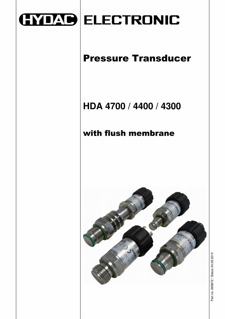
1 General Pressure transmitter HDA 4000 with a flush membrane was designed specifically for applications in which a standard pressure connection could become blocked, clogged or frozen by the particular medium used. Additional fields of application can be found in processes with changing media, in which residues could lead to mixing or contamination of the media. The pressure connection is achieved with a fully-sealed stainless steel front membrane filled internally with a pressure transfer fluid. The process pressure is transmitted hydrostatically to the measurement cell via the pressure transfer fluid. If you have any queries regarding technical details or the suitability of the unit for your application, please contact our Technical Sales department. EDS 4000 pressure switches are individually tested and calibrated at a computer operated test station. The pressure switches are maintenance-free and operate perfectly when used according to the specifications (see Technical Specifications). However, if there is a cause for complaint, please contact HYDAC Service. Interference by anybody other than HYDAC personnel will invalidate all warranty claims.
2 Safety Instructions Before commissioning, check the instrument and any accessories supplied. Before commissioning, please read the operating instructions. Ensure that the instrument is suitable for your application. Incorrect use or the non-compliance with the operating instructions and specifications can lead to damage to property and/or personal injury. Ensure that the measured fluids in contact with the material are compatible and that the overload pressure and burst pressure will not be exceeded.
6 HDA 4700 / 4400 / 4300 with flush membrane
Status 04.09.2013 HYDAC ELECTRONIC GMBH Part no.: 669872
E
3 Installation The units can be mounted directly to the hydraulic system via the thread connection. Please ensure that the flush mounted (external) diaphragm is protected from mechanical damage. The recommended mounting position is vertical with the pressure connection pointing upwards in hydraulic applications. The tightening torque for both G 1/2 thread connectors is 45 Nm. The electrical connection must be carried out by a qualified electrician according to the relevant regulations of the country concerned (VDE 0100 in Germany). Pressure transducers from the HDA 4000 series are marked. A certificate of conformity will be provided on request. The EMV standards: EN 61000-6-1, 2, 3 und 4 apply. However, the stipulations of those standards will be met only if the sensor's housing has been correctly earthed by a qualified electrician. When fitted into a hydraulic block, earthing the block via the hydraulic system is sufficient.
Caution! The HDA 4000 must be fitted using a suitable open-end wrench (across flats 27) on the hexagon nut of the pressure connection. Do not install the device by gripping the housing, as this would damage the housing or the entire unit.
Additional installation suggestions which, from experience, reduce the effect of electromagnetic interference:
• Make line connections as short as possible • Use shielded lines (e.g. LIYCY 4 x 0.5 mm²) • The cable screening must be fitted by qualified personnel subject to the ambient
conditions and with the aim of suppressing interference • Keep the unit well away from the electrical supply lines of power equipment, as well as
from any electrical or electronic equipment causing interference
HDA 4700 / 4400 / 4300 with flush membrane 7
Status 04.09.2013 HYDAC ELECTRONIC GMBH Part no.: 669872
E
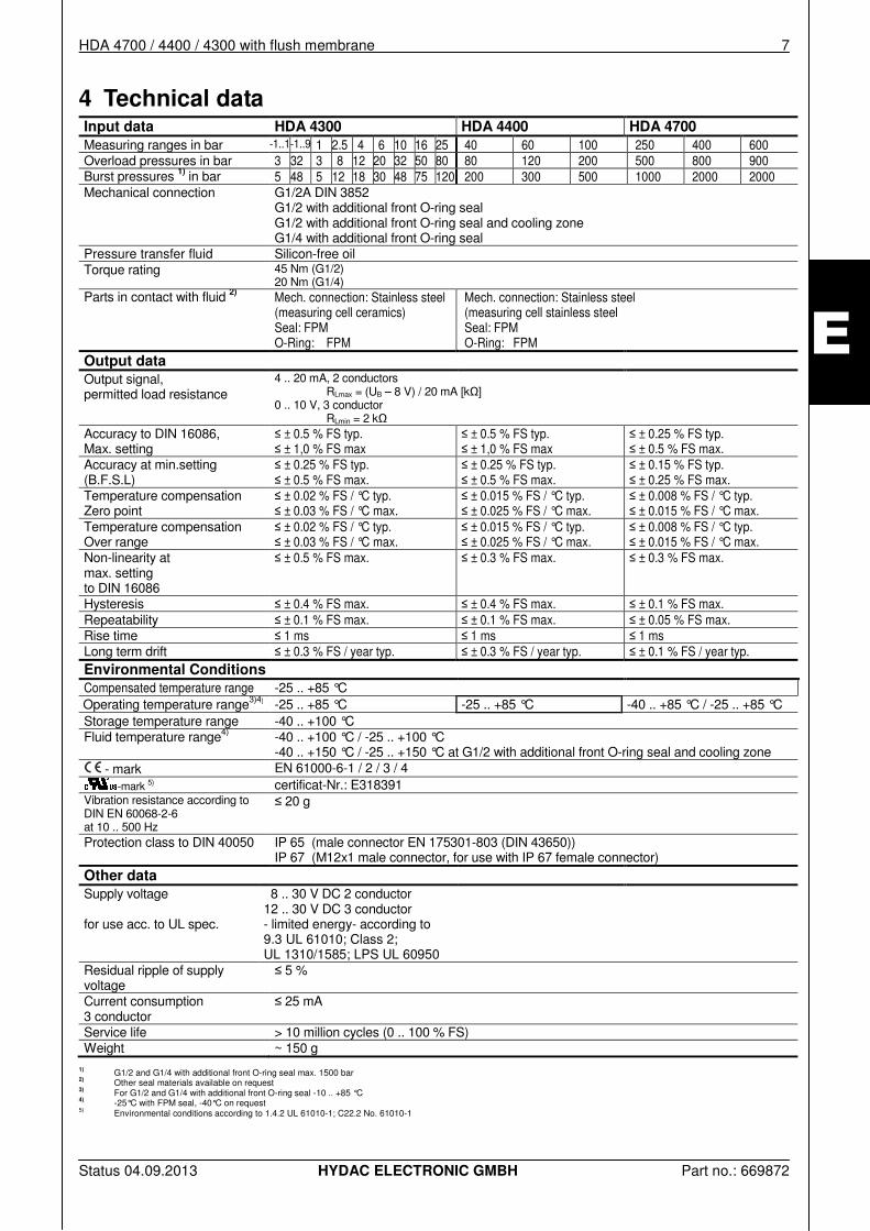
4 Technical data Input data HDA 4300 HDA 4400 HDA 4700
Measuring ranges in bar -1..1-1..9 1 2.5 4 6 10 16 25 40 60 100 250 400 600 Overload pressures in bar 3 32 3 8 12 20 32 50 80 80 120 200 500 800 900 Burst pressures 1) in bar 5 48 5 12 18 30 48 75 120 200 300 500 1000 2000 2000 Mechanical connection G1/2A DIN 3852
G1/2 with additional front O-ring seal G1/2 with additional front O-ring seal and cooling zone G1/4 with additional front O-ring seal
Pressure transfer fluid Silicon-free oil Torque rating 45 Nm (G1/2)
20 Nm (G1/4) Parts in contact with fluid 2) Mech. connection: Stainless steel
(measuring cell ceramics) Seal: FPM O-Ring: FPM
Mech. connection: Stainless steel (measuring cell stainless steel Seal: FPM O-Ring: FPM
Output data
Output signal, permitted load resistance
4 .. 20 mA, 2 conductors RLmax = (UB – 8 V) / 20 mA [kΩ] 0 .. 10 V, 3 conductor RLmin = 2 kΩ
Accuracy to DIN 16086, Max. setting
≤ ± 0.5 % FS typ. ≤ ± 1,0 % FS max
≤ ± 0.5 % FS typ. ≤ ± 1,0 % FS max
≤ ± 0.25 % FS typ. ≤ ± 0.5 % FS max.
Accuracy at min.setting (B.F.S.L)
≤ ± 0.25 % FS typ. ≤ ± 0.5 % FS max.
≤ ± 0.25 % FS typ. ≤ ± 0.5 % FS max.
≤ ± 0.15 % FS typ. ≤ ± 0.25 % FS max.
Temperature compensation Zero point
≤ ± 0.02 % FS / °C typ. ≤ ± 0.03 % FS / °C max.
≤ ± 0.015 % FS / °C typ. ≤ ± 0.025 % FS / °C max.
≤ ± 0.008 % FS / °C typ. ≤ ± 0.015 % FS / °C max.
Temperature compensation Over range
≤ ± 0.02 % FS / °C typ. ≤ ± 0.03 % FS / °C max.
≤ ± 0.015 % FS / °C typ. ≤ ± 0.025 % FS / °C max.
≤ ± 0.008 % FS / °C typ. ≤ ± 0.015 % FS / °C max.
Non-linearity at max. setting to DIN 16086
≤ ± 0.5 % FS max. ≤ ± 0.3 % FS max. ≤ ± 0.3 % FS max.
Hysteresis ≤ ± 0.4 % FS max. ≤ ± 0.4 % FS max. ≤ ± 0.1 % FS max. Repeatability ≤ ± 0.1 % FS max. ≤ ± 0.1 % FS max. ≤ ± 0.05 % FS max. Rise time ≤ 1 ms ≤ 1 ms ≤ 1 ms Long term drift ≤ ± 0.3 % FS / year typ. ≤ ± 0.3 % FS / year typ. ≤ ± 0.1 % FS / year typ. Environmental Conditions Compensated temperature range -25 .. +85 °C Operating temperature range3)4) -25 .. +85 °C -25 .. +85 °C -40 .. +85 °C / -25 .. +85 °C Storage temperature range -40 .. +100 °C Fluid temperature range4) -40 .. +100 °C / -25 .. +100 °C
-40 .. +150 °C / -25 .. +150 °C at G1/2 with additional front O-ring seal and cooling zone - mark EN 61000-6-1 / 2 / 3 / 4
-mark 5) certificat-Nr.: E318391 Vibration resistance according to DIN EN 60068-2-6 at 10 .. 500 Hz
≤ 20 g
Protection class to DIN 40050 IP 65 (male connector EN 175301-803 (DIN 43650)) IP 67 (M12x1 male connector, for use with IP 67 female connector)
Other data
Supply voltage for use acc. to UL spec.
8 .. 30 V DC 2 conductor 12 .. 30 V DC 3 conductor - limited energy- according to 9.3 UL 61010; Class 2; UL 1310/1585; LPS UL 60950
Residual ripple of supply voltage
≤ 5 %
Current consumption 3 conductor
≤ 25 mA
Service life > 10 million cycles (0 .. 100 % FS) Weight ~ 150 g
1) G1/2 and G1/4 with additional front O-ring seal max. 1500 bar 2) Other seal materials available on request 3) For G1/2 and G1/4 with additional front O-ring seal -10 .. +85 °C 4)
-25°C with FPM seal, -40°C on request 5) Environmental conditions according to 1.4.2 UL 61010-1; C22.2 No. 61010-1
8 HDA 4700 / 4400 / 4300 with flush membrane
Status 04.09.2013 HYDAC ELECTRONIC GMBH Part no.: 669872
E
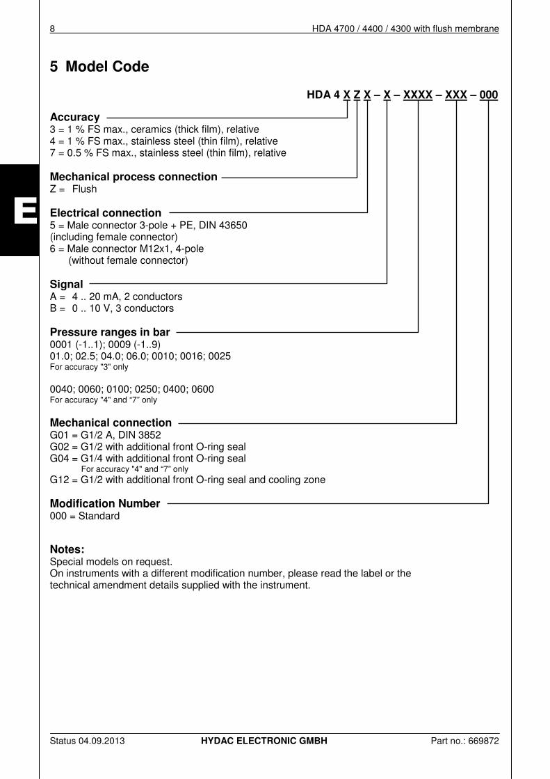
5 Model Code
HDA 4 X Z X – X – XXXX – XXX – 000
Accuracy 3 = 1 % FS max., ceramics (thick film), relative 4 = 1 % FS max., stainless steel (thin film), relative 7 = 0.5 % FS max., stainless steel (thin film), relative Mechanical process connection Z = Flush Electrical connection 5 = Male connector 3-pole + PE, DIN 43650 (including female connector) 6 = Male connector M12x1, 4-pole
(without female connector) Signal A = 4 .. 20 mA, 2 conductors B = 0 .. 10 V, 3 conductors Pressure ranges in bar 0001 (-1..1); 0009 (-1..9) 01.0; 02.5; 04.0; 06.0; 0010; 0016; 0025 For accuracy "3" only 0040; 0060; 0100; 0250; 0400; 0600 For accuracy "4" and “7” only Mechanical connection G01 = G1/2 A, DIN 3852 G02 = G1/2 with additional front O-ring seal G04 = G1/4 with additional front O-ring seal For accuracy "4" and “7” only G12 = G1/2 with additional front O-ring seal and cooling zone Modification Number 000 = Standard Notes: Special models on request. On instruments with a different modification number, please read the label or the technical amendment details supplied with the instrument.
HDA 4700 / 4400 / 4300 with flush membrane 9
Status 04.09.2013 HYDAC ELECTRONIC GMBH Part no.: 669872
E
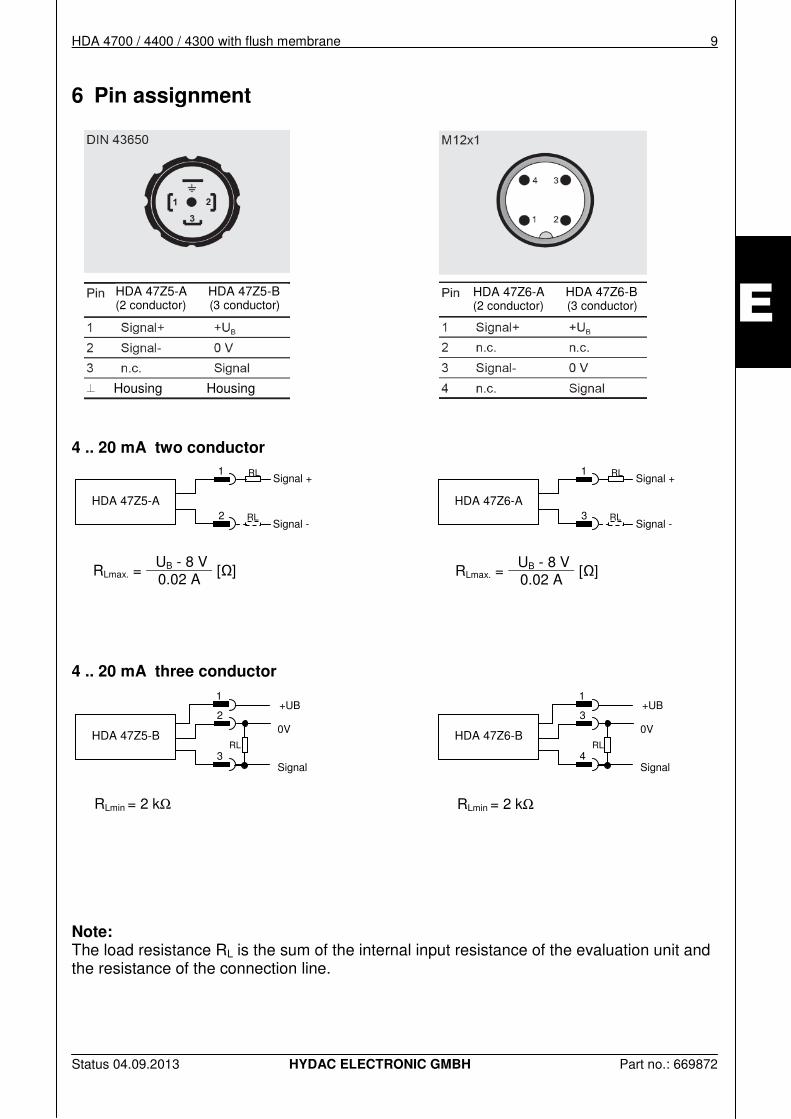
6 Pin assignment
4 .. 20 mA two conductor
4 .. 20 mA three conductor
RLmin = 2 kΩ
RLmin = 2 kΩ
Note: The load resistance RL is the sum of the internal input resistance of the evaluation unit and the resistance of the connection line.
RLmax. = UB - 8 V
[Ω] 0.02 A
RLmax. = UB - 8 V
[Ω] 0.02 A
HDA 47Z5-A HDA 47Z5-B (2 conductor) (3 conductor)
HDA 47Z6-A HDA 47Z6-B (2 conductor) (3 conductor)
HDA 47Z6-A
RL
RL
Signal + 1
Signal - 3
HDA 47Z6-B
+UB
0V
Signal
RL
1
3
4
HDA 47Z5-A
RL
RL
Signal + 1
Signal - 2
HDA 47Z5-B
+UB
0V
Signal
RL
1
2
3
Housing Housing
10 HDA 4700 / 4400 / 4300 with flush membrane
Status 04.09.2013 HYDAC ELECTRONIC GMBH Part no.: 669872
E
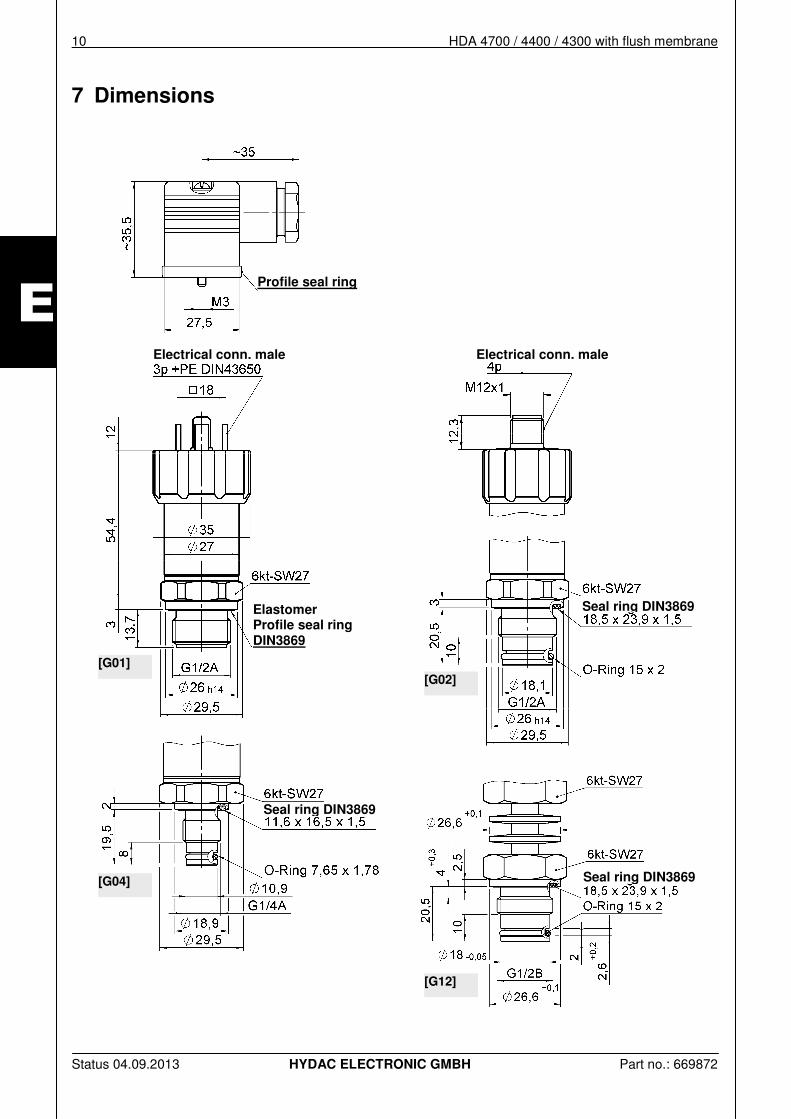
7 Dimensions
[G01]
[G02]
[G04]
[G12]
Profile seal ring
Electrical conn. male Electrical conn. male
Seal ring DIN3869 Elastomer Profile seal ring DIN3869
Seal ring DIN3869
Seal ring DIN3869
HDA 4700 / 4400 / 4300 with flush membrane 11
Status 04.09.2013 HYDAC ELECTRONIC GMBH Part no.: 669872
E
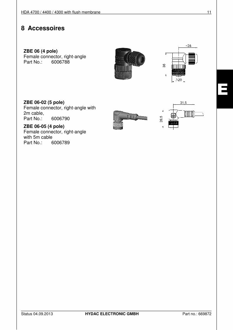
8 Accessoires
ZBE 06 (4 pole) Female connector, right-angle Part No.: 6006788
ZBE 06-02 (5 pole) Female connector, right-angle with 2m cable, Part No.: 6006790
ZBE 06-05 (4 pole) Female connector, right-angle with 5m cable Part No.: 6006789
12 HDA 4700 / 4400 / 4300 with flush membrane
Status 04.09.2013 HYDAC ELECTRONIC GMBH Part no.: 669872
E
HYDAC ELECTRONIC GMBH Hauptstr. 27 D-66128 Saarbrücken Germany Web: www.hydac.com Email: [email protected] Phone: +49 (0)6897 509-01 Fax.: +49 (0)6897 509-1726
HYDAC Service If you have any questions concerning repairwork, please don’t hesitate to contact HYDAC Service:
HYDAC SERVICE GMBH Hauptstr. 27 D-66128 Saarbrücken Germany Phone: +49 (0)6897 509-1936 Fax.: +49 (0) 6897 509-1933
Note
The information and particulars provided in this manual apply to the operating conditions and applications described herein. For applications and operating conditions not described here, please contact the relevant technical department. If you have any questions, suggestions, or encounter any problems of a technical nature, please contact your Hydac representative. Subject to technical modifications.
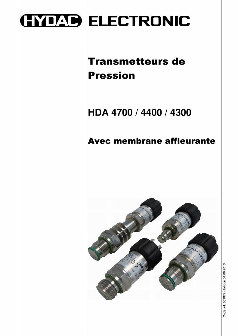
Transmetteurs de
Pression
HDA 4700 / 4400 / 4300
Avec membrane affleurante
Cod
e ar
t. 6
6987
2 / E
ditio
n 04
.09.
2013
2 HDA 4700 / 4400 / 4300 avec membrane affleurante
Edition 04.09.2013 HYDAC ELECTRONIC GMBH Code article : 669872
F
HDA 4700 / 4400 / 4300 avec membrane affleurante 3
Edition 04.09.2013 HYDAC ELECTRONIC GMBH Code article : 669872
F
Sommaire
1 Généralités ___________________________________________ 5
2 Consignes de Sécurité _________________________________ 5
3 Montage _____________________________________________ 6
4 Caractéristiques Techniques ____________________________ 7
5 Code de Commande ___________________________________ 8
6 Raccordement électrique _______________________________ 9
7 Dimensions __________________________________________ 10
8 Accessoires _________________________________________ 11
4 HDA 4700 / 4400 / 4300 Avec membrane affleurante
Edition 04.09.2013 HYDAC ELECTRONIC GMBH Code article : 669872
F
Avant-propos
À l'attention des acquéreurs d'un produit que nous avons fabriqué. Nous avons rassemblé dans cette documentation les recommandations essentielles pour l'utilisation et la maintenance de ce produit. Cette notice a pour objectif de simplifier la prise de connaissance du produit et de permettre une exploitation optimale de ses possibilités d'utilisation, conformément à l'usage prévu. Ce document doit toujours être disponible sur le lieu d'utilisation. Veuillez noter que les informations fournies dans cette documentation correspondent à la technique de l'appareil au moment de l'élaboration de ce document. Pour cette raison, les différentes données techniques, illustrations et mesures sont susceptibles de diverger. Si, lors de la lecture de ce manuel, vous deviez détecter des erreurs ou encore si vous aviez des suggestions ou des remarques, veuillez vous adresser à : HYDAC ELECTRONIC GMBH Documentation technique : Hauptstrasse 27 D-66128 Saarbrücken -Allemagne- Tél.: +49(0)6897 / 509–01 Fax: +49(0)6897 / 509-1726 Email: [email protected] La rédaction vous est reconnaissante de votre participation. "De la pratique vers la pratique"
HDA 4700 / 4400 / 4300 avec membrane affleurante 5
Edition 04.09.2013 HYDAC ELECTRONIC GMBH Code article : 669872
F
1 Généralités Le transmetteur de pression HDA 4000 avec membrane affleurante a été spécialement conçu pour les applications dans lesquelles les fluides utilisés peuvent colmater, coller ou geler un raccord de pression standard. Les processus avec fluides alternants, dans lesquels des résidus peuvent provoquer un mélange ou des impuretés, constituent d'autres champs d'application. Le raccordement pression est raccordé de manière frontale grâce à une membrane en inox soudée et il est rempli en interne avec un liquide de remplissage du séparateur qui transmet hydrostatiquement la pression process à la cellule de mesure. En cas de questions concernant les données techniques et l'aptitude d'utilisation de l'appareil, veuillez vous adresser à notre service commercial. Chaque transmetteur de pression basé sur la série HDA 4000 est aligné et soumis à un test final sur un poste d'essai assisté par ordinateur. Les appareils ne nécessitent aucun entretien et fonctionnent parfaitement dans les conditions d’utilisation (voir données techniques) spécifiées. Si malgré tout un dysfonctionnement devait survenir, veuillez vous mettre en relation avec HYDAC-Service. Toute intervention extérieure dans l’appareil entraînent l’annulation de la garantie.
2 Consignes de Sécurité Avant la première mise en service, merci de vérifier le bon état du matériel et de ses accessoires éventuels. Lisez la notice d’utilisation avant la mise en service, et assurez-vous que l’appareil convienne à votre utilisation. Une mauvaise manipulation comme par exemple le non respect des caractéristiques techniques ou une mauvaise mise en œuvre peut causer des dégâts matériels et/ou humains. Vérifier la compatibilité des fluides de mesure avec les matériaux utilisés par le manocontacteur. Tenir compte également de la pression de surcharge et la pression d'éclatement.
6 HDA 4700 / 4400 / 4300 Avec membrane affleurante
Edition 04.09.2013 HYDAC ELECTRONIC GMBH Code article : 669872
F
3 Montage Le transmetteur peut être monté directement sur un bloc hydraulique au moyen d'un raccord taraudé. Il faut ici veiller à ce que la membrane affleurante (externe) soit protégée de dommages mécaniques. Le sens de montage recommandé pour les utilisations hydrauliques est vertical, le raccord de pression étant dirigé vers le haut. Le couple de serrage pour chaque raccord taraudé G 1/2 est à 45 Nm. Le raccordement doit être réalisé par du personnel qualifié selon chaque prescription nationale (VDE 0100 en Allemagne). Chaque transmetteur de pression basé sur la série HDA 4000 possède le marquage . Un certificat de conformité est disponible sur demande. Les normes EMV applicables: EN 61000–6–1,–2,–3 et –4. Les éxigences de ces normes ne seront atteintes que par une mise à la terre correcte par un spécialiste du corps du transmetteur. En cas de vissage dans un bloc hydraulique, le fait que le bloc est relié à la terre via le système hydraulique est suffisant.
ATTENTION ! Le HDA 4000 doit être monté avec une clé adaptée (de 27) au niveau du raccord métallique 6 pans. Un mauvais montage comme par exemple le vissage par le corps du capteur peut endommager le corps de l'appareil et peut entrainer la destruction du capteur.
Remarques complémentaires, pour diminuer l'influence des perturbations électromagnétiques:
• Les raccords électriques doivent être les plus courts possibles. • Utiliser des câbles blindés (p.ex. LIYCY 4 x 0,5 mm²) • Le câble blindé est à mettre en œuvre en fonction des conditions environnantes par des
spécialistes afin de diminuer les perturbations électromagnétiques. • Eviter si possible de placer l'appareil à proximité d'appareils électriques ou électroniques
générateurs de perturbations électromagnétiques.
HDA 4700 / 4400 / 4300 avec membrane affleurante 7
Edition 04.09.2013 HYDAC ELECTRONIC GMBH Code article : 669872
F
4 Caractéristiques Techniques Valeurs d'entrée HDA 4300 HDA 4400 HDA 4700
Plages de mesure en bar -1..1 -1..9 1 2,5 4 6 10 16 25 40 60 100 250 400 600
Plages de surcharge en bar 3 32 3 8 12 20 32 50 80 80 120 200 500 800 900
Pression d‘éclatement 1) en bar 5 48 5 12 18 30 48 75 120 200 300 500 1000 2000 2000
Raccordement mécanique G1/2A DIN 3852 G1/2 avec joint torique frontal supplémentaire G1/2 avec joint torique frontal supplémentaire et zone de refroidissement G1/4 avec joint torique frontal supplémentaire
Liquide de remplissage du séparateur Huile exempte de silicone Couple de serrage 45 Nm (G1/2)
20 Nm (G1/4) Pièces en contact avec fluide 2) Acier inoxydable
(cellule de mesure en céramique) Joint : FPM Joint torique : FPM
Acier inoxydable (cellule de mesure en acier inoxydable) Joint : FPM Joint torique : FPM
Valeurs de sortie
Signal de sortie, charge autorisée
4 .. 20 mA, bipolaire RLmax = (UB – 8 V) / 20 mA [kΩ] 0 .. 10 V, tripolaire RLmin = 2 kΩ
Précision selon norme DIN 16086, Réglage du seuil limite
≤ ± 0,5 % PE typ ≤ ± 1,0 % FS max
≤ ± 0,5 % PE typ ≤ ± 1,0 % FS max
≤ ± 0,25 % PE typ ≤ ± 0,5 % FS max.
Précision réglage du valeur minimum (B.F.S.L.)
≤ ± 0,25 % PE typ ≤ ± 0,5 % FS max.
≤ ± 0,25 % PE typ ≤ ± 0,5 % FS max.
≤ ± 0,15 % PE typ ≤ ± 0,25 % FS max.
Compensation de température au point zéro
≤ ± 0,02 % FS / °C typ. ≤ ± 0,03 % FS / °C max.
≤ ± 0,015 % FS / °C typ. ≤ ± 0,025 % FS / °C max.
≤ ± 0,008 % FS / °C typ. ≤ ± 0,015 % FS / °C max.
Compensation de température sur la sensibilité
≤ ± 0,02 % FS / °C typ. ≤ ± 0,03 % FS / °C max.
≤ ± 0,015 % FS / °C typ. ≤ ± 0,025 % FS / °C max.
≤ ± 0,008 % FS / °C typ. ≤ ± 0,015 % FS / °C max.
Non linéarité avec le réglage du seuil selon DIN 16086
≤ ± 0,5 % FS max. ≤ ± 0,3 % FS max. ≤ ± 0,3 % FS max.
Hysteresis ≤ ± 0,4 % FS max. ≤ ± 0,4 % FS max. ≤ ± 0,1 % FS max. Répétabilité ≤ ± 0,1 % FS max. ≤ ± 0,1 % FS max. ≤ ± 0,05 % FS max. Temps de réponse ≤ 1 ms ≤ 1 ms ≤ 1 ms Dérive dans le temps ≤ ± 0,3 % PE / an typ. ≤ ± 0,3 % PE / an typ. ≤ ± 0,1 % PE / an typ. Conditions environnementales Plage de température compensée -25 .. +85 °C Plage de température d'utilisation
3)4) -25 .. +85 °C -25 .. +85 °C -40 .. +85 °C / -25 .. +85 °CPlage de température de stockage -40 .. +100 °C Plage de température du fluide4) -40 .. +100 °C / -25 .. +100 °C
-40 .. +150 °C / -25 .. +150 °C pour G1/2 avec joint torique frontal supplém. et zone de refroidissement
Sigle EN 61000-6-1 / 2/ 3/ 4 -signe 5) Certificat-Nr.: E318391
Résistance aux vibrations DIN EN 60068-2-6 à 10 .. 500 Hz
≤ 20 g
Indice de protection selon DIN 40050
IP 65 (connecteur EN 175301-803 (DIN 43650)) IP 67 (connecteur M12x1, utilisant une prise femelle IP 67)
Autres valeurs Tension d‘alimentation Pour utilisation selon spécification UL
8 .. 30 V DC 2 conducteurs 12 .. 30 V DC 3 conducteurs - limited energy- selon 9.3 UL 61010; Class 2; UL 1310/1585; LPS UL 60950
Oscillation résiduelle de la tension d'alimentation
≤ 5 %
Consommation de courant tripolaire ≤ 25 mA Durée de vie > 10 millions de cycles en pleine charge (0 .. 100 % PE) Masse ~ 150 g
1) G1/2 et G1/4 avec joint torique frontal supplémentaire max. 1500 bar 2) Autres matériaux de joints sur demande 3) G1/2 et G1/4 avec joint torique frontal supplémentaire -10 .. +85 C 4)
-25°C avec FPM joint, -40°C sur demande 5) Conditions environnementales selon 1.4.2 UL 61010-1; C22.2 No. 61010-1
8 HDA 4700 / 4400 / 4300 Avec membrane affleurante
Edition 04.09.2013 HYDAC ELECTRONIC GMBH Code article : 669872
F
5 Code de Commande
HDA 4 X Z X – X – XXXX – XXX – 000
Précision 3 = 1 % FS max., céramique (couche épaisse), relative 4 = 1 % FS max., acier inox (couche mince), relative 7 = 0,5 % FS max., acier inox (couche mince), relative Raccordement procès mécanique Z = Affleurant Raccord électrique 5 = connecteur 3 pôles + PE, DIN 43650 (livré avec connecteur) 6 = Embase M12x1, 4pôles
(sans connecteur) Signal A = 4 .. 20 mA, Bipolaire B = 0 .. 10 V, Tripolaire Plages de pression en bar 0001 (-1..1); 0009 (-1..9) 01,0; 02,5; 04,0; 06,0; 0010; 0016; 0025 (Uniquement pour précision "3") 0040; 0060; 0100; 0250; 0400; 0600 (Uniquement pour précision "4" et "7") Raccord mécanique G01 = G1/2 A, DIN 3852 G02 = G1/2 avec joint torique frontal supplémentaire G03 = G1/4 avec joint torique frontal supplémentaire (Uniquement pour précision "4" et "7") G12 = G1/2 avec joint torique frontal supplémentaire et zone de refroidissement Numéro de modification 000 = standard Remarques : Exécutions spéciales sur demande. Pour les appareils ayant un autre indice de modification, veuillez respecter la plaque signalétique ou la description des modifications techniques jointe à la livraison.
HDA 4700 / 4400 / 4300 avec membrane affleurante 9
Edition 04.09.2013 HYDAC ELECTRONIC GMBH Code article : 669872
F
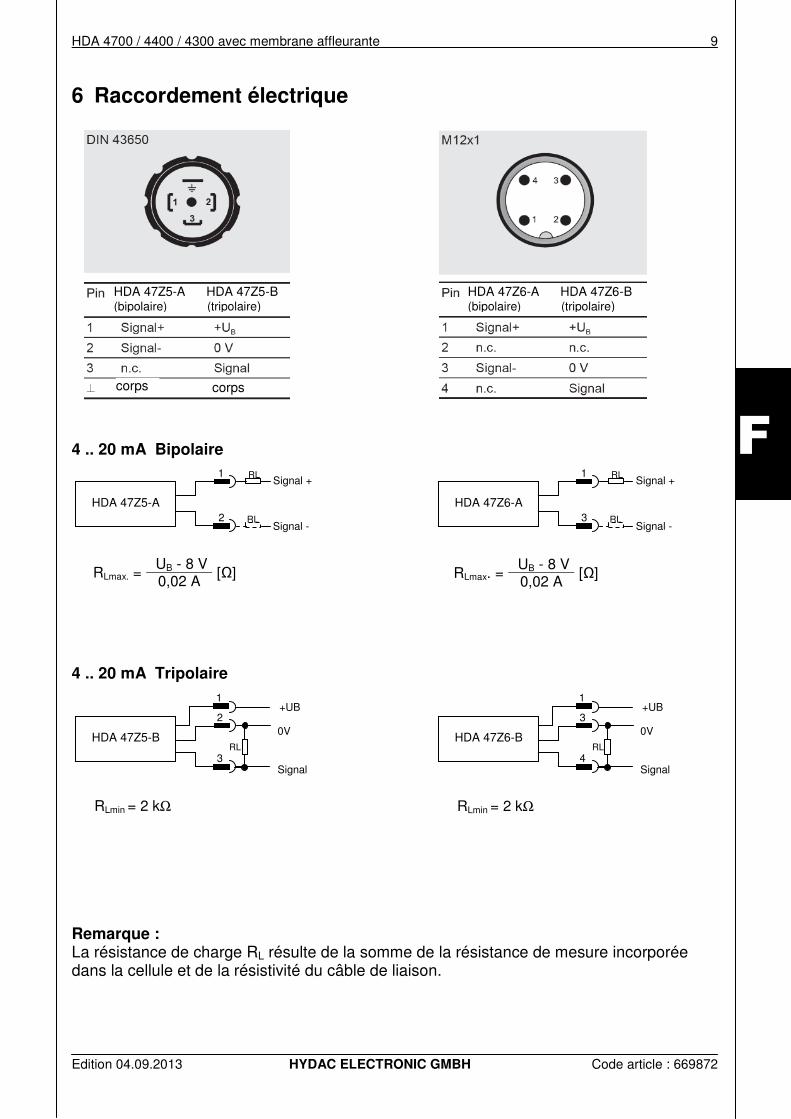
6 Raccordement électrique
4 .. 20 mA Bipolaire
4 .. 20 mA Tripolaire
RLmin = 2 kΩ
RLmin = 2 kΩ
Remarque : La résistance de charge RL résulte de la somme de la résistance de mesure incorporée dans la cellule et de la résistivité du câble de liaison.
RLmax. = UB - 8 V
[Ω] 0,02 A
RLmax. = UB - 8 V
[Ω] 0,02 A
HDA 47Z5-A HDA 47Z5-B (bipolaire) (tripolaire)
HDA 47Z6-A
RL
RL
Signal + 1
Signal - 3
HDA 47Z6-B
+UB
0V
Signal
RL
1
3
4
HDA 47Z5-A
RL
RL
Signal + 1
Signal - 2
HDA 47Z5-B
+UB
0V
Signal
RL
1
2
3
HDA 47Z6-A HDA 47Z6-B (bipolaire) (tripolaire)
corps corps
10 HDA 4700 / 4400 / 4300 Avec membrane affleurante
Edition 04.09.2013 HYDAC ELECTRONIC GMBH Code article : 669872
F
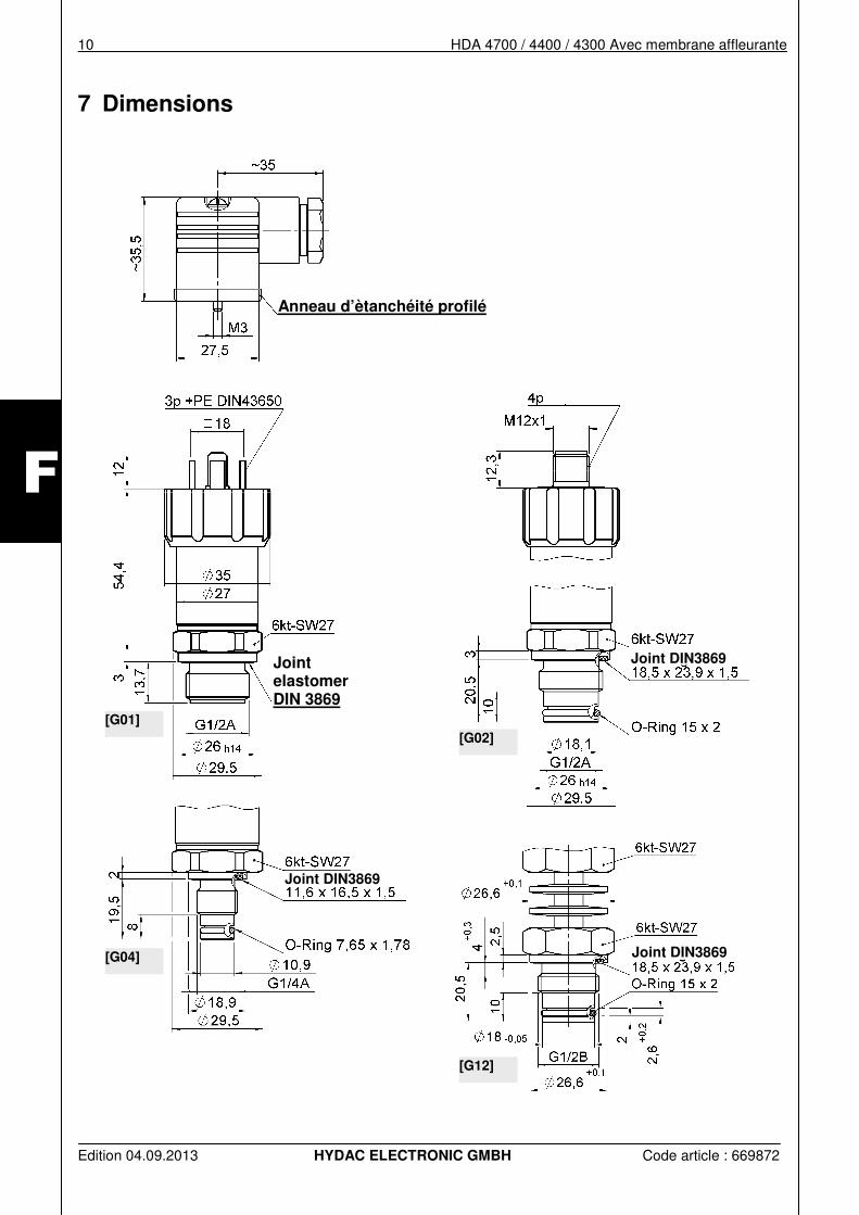
7 Dimensions
[G01]
[G02]
[G04]
[G12]
Anneau d’ètanchéité profilé
Joint DIN3869 Joint elastomer DIN 3869
Joint DIN3869
Joint DIN3869
HDA 4700 / 4400 / 4300 avec membrane affleurante 11
Edition 04.09.2013 HYDAC ELECTRONIC GMBH Code article : 669872
F
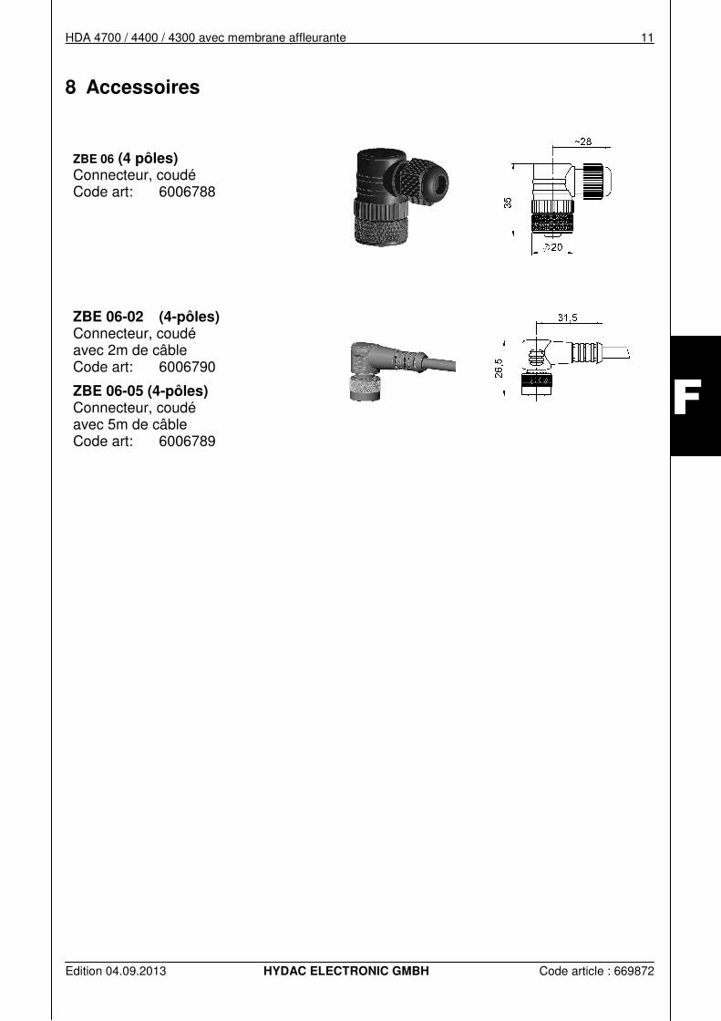
8 Accessoires
ZBE 06 (4 pôles) Connecteur, coudé Code art: 6006788
ZBE 06-02 (4-pôles) Connecteur, coudé avec 2m de câble Code art: 6006790
ZBE 06-05 (4-pôles) Connecteur, coudé avec 5m de câble Code art: 6006789
12 HDA 4700 / 4400 / 4300 Avec membrane affleurante
Edition 04.09.2013 HYDAC ELECTRONIC GMBH Code article : 669872
F
HYDAC ELECTRONIC GMBH Hauptstr.27 D-66128 Saarbrücken Allemagne Web: www.hydac.com Email: [email protected] Tél. : +49(0)6897 / 509-01 Fax: +49(0)6897 / 509-1726
HYDAC Service HYDAC Service se tient à votre disposition pour toute question concernant les réparations.
HYDAC Service GmbH Hauptstr.27 D-66128 Saarbrücken Allemagne Tél. : +49 (0) 6897 / 509 – 1936 Fax : +49 (0) 6897 / 509 – 1933
Remarques
Les données de ce prospectus se réfèrent aux conditions de fonctionnement et d’utilisation décrites. Pour des cas d'utilisation et/ou conditions de fonctionnement différents, veuillez vous adresser au service technique compétent. Pour toute question technique, demande de conseils ou en cas de panne, veuillez vous mettre en relation avec votre représentation HYDAC. Sous réserve de modifications techniques.