Embed Size (px)
Citation preview
Balluff Network Interface EtherNet/IP™
www.balluff.com 1
BNI EIP-104-105-Z015 16 Eingänge / 16 Inputs
BNI EIP-202-105-Z015 8 Ausgänge / 8 Outputs
BNI EIP-302-105-Z015 16 Eingänge oder Ausgänge / 16 Inputs or Outputs
BNI EIP-502-105-Z015 16 Eingänge oder Ausgänge oder IO-Link / 16 Inputs or Outputs or IO-Link
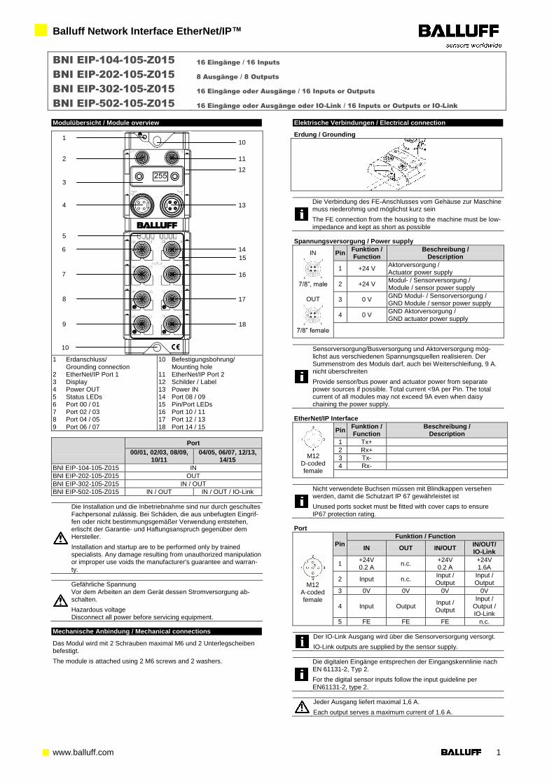
Modulübersicht / Module overview
1 Erdanschluss/
Grounding connection 2 EtherNet/IP Port 1 3 Display 4 Power OUT 5 Status LEDs 6 Port 00 / 01 7 Port 02 / 03 8 Port 04 / 05 9 Port 06 / 07
10 Befestigungsbohrung/ Mounting hole
11 EtherNet/IP Port 2 12 Schilder / Label 13 Power IN 14 Port 08 / 09 15 Pin/Port LEDs 16 Port 10 / 11 17 Port 12 / 13 18 Port 14 / 15
Port
00/01, 02/03, 08/09, 10/11
04/05, 06/07, 12/13, 14/15
BNI EIP-104-105-Z015 IN
BNI EIP-202-105-Z015 OUT
BNI EIP-302-105-Z015 IN / OUT
BNI EIP-502-105-Z015 IN / OUT IN / OUT / IO-Link
Die Installation und die Inbetriebnahme sind nur durch geschultes Fachpersonal zulässig. Bei Schäden, die aus unbefugten Eingrif-fen oder nicht bestimmungsgemäßer Verwendung entstehen, erlischt der Garantie- und Haftungsanspruch gegenüber dem Hersteller.
Installation and startup are to be performed only by trained specialists. Any damage resulting from unauthorized manipulation or improper use voids the manufacturer's guarantee and warran-ty.
Gefährliche Spannung Vor dem Arbeiten an dem Gerät dessen Stromversorgung ab-schalten.
Hazardous voltage Disconnect all power before servicing equipment.
Mechanische Anbindung / Mechanical connections
Das Modul wird mit 2 Schrauben maximal M6 und 2 Unterlegscheiben befestigt.
The module is attached using 2 M6 screws and 2 washers.
Elektrische Verbindungen / Electrical connection
Erdung / Grounding
Die Verbindung des FE-Anschlusses vom Gehäuse zur Maschine muss niederohmig und möglichst kurz sein
The FE connection from the housing to the machine must be low-
impedance and kept as short as possible
Spannungsversorgung / Power supply
IN
7/8”, male
OUT
7/8” female
Pin Funktion / Function
Beschreibung / Description
1 +24 V Aktorversorgung / Actuator power supply
2 +24 V Modul- / Sensorversorgung / Module / sensor power supply
3 0 V GND Modul- / Sensorversorgung / GND Module / sensor power supply
4 0 V GND Aktorversorgung / GND actuator power supply
Sensorversorgung/Busversorgung und Aktorversorgung mög-lichst aus verschiedenen Spannungsquellen realisieren. Der Summenstrom des Moduls darf, auch bei Weiterschleifung, 9 A. nicht überschreiten
Provide sensor/bus power and actuator power from separate power sources if possible. Total current <9A per Pin. The total current of all modules may not exceed 9A even when daisy chaining the power supply.
EtherNet/IP Interface
M12
D-coded female
Pin Funktion / Function
Beschreibung / Description
1 Tx+
2 Rx+
3 Tx-
4 Rx-
Nicht verwendete Buchsen müssen mit Blindkappen versehen werden, damit die Schutzart IP 67 gewährleistet ist
Unused ports socket must be fitted with cover caps to ensure IP67 protection rating.
Port
M12
A-coded female
Pin
Funktion / Function
IN OUT IN/OUT IN/OUT/ IO-Link
1 +24V 0.2 A
n.c. +24V 0.2 A
+24V 1.6A
2 Input n.c. Input / Output
Input / Output
3 0V 0V 0V 0V
4 Input Output Input / Output
Input / Output / IO-Link
5 FE FE FE n.c.
Der IO-Link Ausgang wird über die Sensorversorgung versorgt.
IO-Link outputs are supplied by the sensor supply.
Die digitalen Eingänge entsprechen der Eingangskennlinie nach EN 61131-2, Typ 2.
For the digital sensor inputs follow the input guideline per EN61131-2, type 2.
Jeder Ausgang liefert maximal 1,6 A.
Each output serves a maximum current of 1.6 A.
10
2
3
4
5
15
13
12
11
1
10
16
17
18
7
8
9
6 14
Balluff Network Interface EtherNet/IP™
www.balluff.com 2
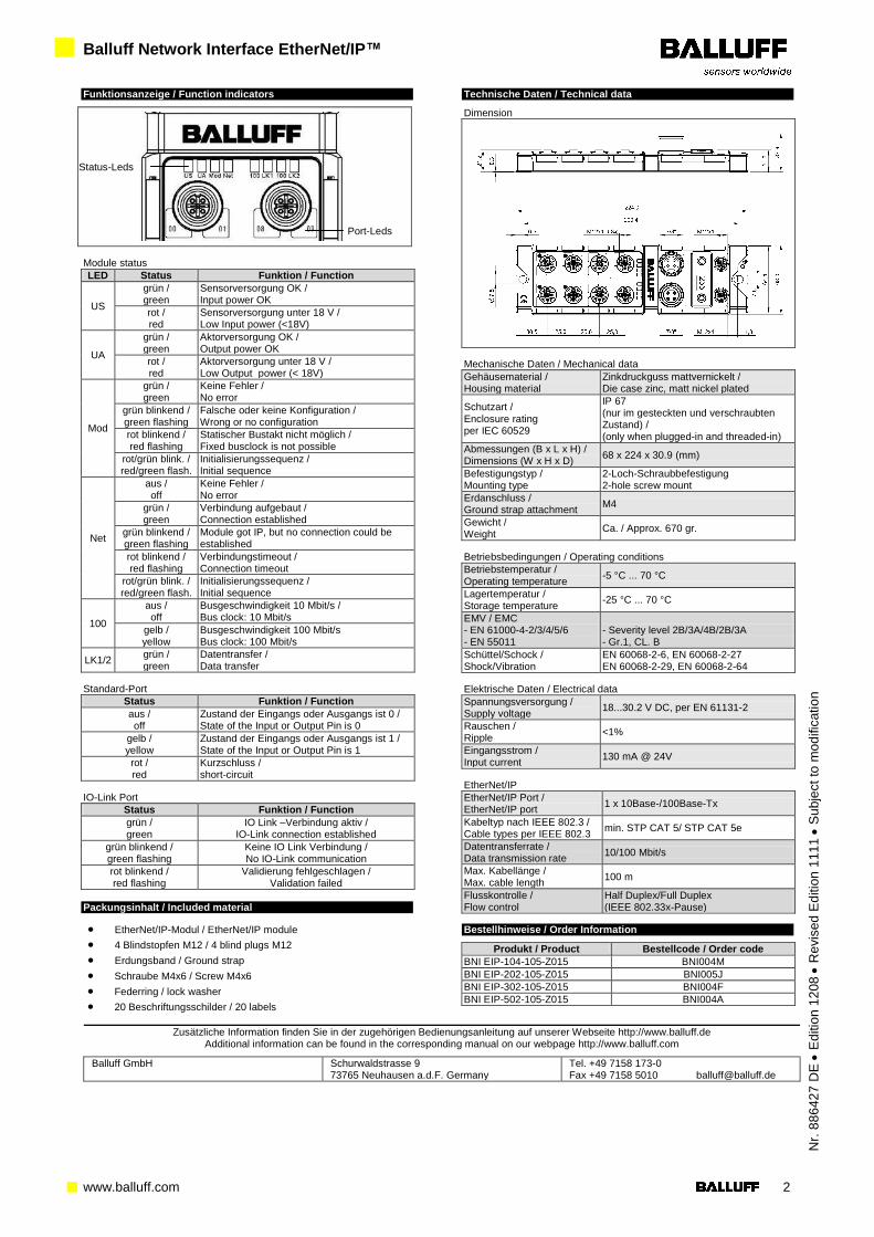
Funktionsanzeige / Function indicators
Module status
LED Status Funktion / Function
US
grün / green
Sensorversorgung OK / Input power OK
rot / red
Sensorversorgung unter 18 V / Low Input power (<18V)
UA
grün / green
Aktorversorgung OK / Output power OK
rot / red
Aktorversorgung unter 18 V / Low Output power (< 18V)
Mod
grün / green
Keine Fehler / No error
grün blinkend / green flashing
Falsche oder keine Konfiguration / Wrong or no configuration
rot blinkend / red flashing
Statischer Bustakt nicht möglich / Fixed busclock is not possible
rot/grün blink. / red/green flash.
Initialisierungssequenz / Initial sequence
Net
aus / off
Keine Fehler / No error
grün / green
Verbindung aufgebaut / Connection established
grün blinkend / green flashing
Module got IP, but no connection could be established
rot blinkend / red flashing
Verbindungstimeout / Connection timeout
rot/grün blink. / red/green flash.
Initialisierungssequenz / Initial sequence
100
aus / off
Busgeschwindigkeit 10 Mbit/s / Bus clock: 10 Mbit/s
gelb / yellow
Busgeschwindigkeit 100 Mbit/s Bus clock: 100 Mbit/s
LK1/2 grün / green
Datentransfer / Data transfer
Standard-Port
Status Funktion / Function
aus / off
Zustand der Eingangs oder Ausgangs ist 0 / State of the Input or Output Pin is 0
gelb / yellow
Zustand der Eingangs oder Ausgangs ist 1 / State of the Input or Output Pin is 1
rot / red
Kurzschluss / short-circuit
IO-Link Port
Status Funktion / Function
grün / green
IO Link –Verbindung aktiv / IO-Link connection established
grün blinkend / green flashing
Keine IO Link Verbindung / No IO-Link communication
rot blinkend / red flashing
Validierung fehlgeschlagen / Validation failed
Packungsinhalt / Included material
EtherNet/IP-Modul / EtherNet/IP module
4 Blindstopfen M12 / 4 blind plugs M12
Erdungsband / Ground strap
Schraube M4x6 / Screw M4x6
Federring / lock washer
20 Beschriftungsschilder / 20 labels
Technische Daten / Technical data
Dimension
Mechanische Daten / Mechanical data
Gehäusematerial / Housing material
Zinkdruckguss mattvernickelt / Die case zinc, matt nickel plated
Schutzart / Enclosure rating per IEC 60529
IP 67 (nur im gesteckten und verschraubten Zustand) / (only when plugged-in and threaded-in)
Abmessungen (B x L x H) / Dimensions (W x H x D)
68 x 224 x 30.9 (mm)
Befestigungstyp / Mounting type
2-Loch-Schraubbefestigung 2-hole screw mount
Erdanschluss / Ground strap attachment
M4
Gewicht / Weight
Ca. / Approx. 670 gr.
Betriebsbedingungen / Operating conditions
Betriebstemperatur / Operating temperature
-5 °C ... 70 °C
Lagertemperatur / Storage temperature
-25 °C ... 70 °C
EMV / EMC - EN 61000-4-2/3/4/5/6 - EN 55011
- Severity level 2B/3A/4B/2B/3A - Gr.1, CL. B
Schüttel/Schock / Shock/Vibration
EN 60068-2-6, EN 60068-2-27 EN 60068-2-29, EN 60068-2-64
Elektrische Daten / Electrical data
Spannungsversorgung / Supply voltage
18...30.2 V DC, per EN 61131-2
Rauschen / Ripple
<1%
Eingangsstrom / Input current
130 mA @ 24V
EtherNet/IP
EtherNet/IP Port / EtherNet/IP port
1 x 10Base-/100Base-Tx
Kabeltyp nach IEEE 802.3 / Cable types per IEEE 802.3
min. STP CAT 5/ STP CAT 5e
Datentransferrate / Data transmission rate
10/100 Mbit/s
Max. Kabellänge / Max. cable length
100 m
Flusskontrolle / Flow control
Half Duplex/Full Duplex (IEEE 802.33x-Pause)
Bestellhinweise / Order Information
Produkt / Product Bestellcode / Order code
BNI EIP-104-105-Z015 BNI004M
BNI EIP-202-105-Z015 BNI005J
BNI EIP-302-105-Z015 BNI004F
BNI EIP-502-105-Z015 BNI004A
Zusätzliche Information finden Sie in der zugehörigen Bedienungsanleitung auf unserer Webseite http://www.balluff.de Additional information can be found in the corresponding manual on our webpage http://www.balluff.com
Balluff GmbH Schurwaldstrasse 9 73765 Neuhausen a.d.F. Germany
Tel. +49 7158 173-0 Fax +49 7158 5010 [email protected]
Nr.
88
642
7 D
E
Ed
itio
n 1
208
R
evis
ed
Ed
itio
n 1
11
1
Su
bje
ct
to m
od
ific
atio
n
Port-Leds
Status-Leds