Embed Size (px)
Citation preview
Maße / Dimensions in mm GD – 1
< 12 arcmin
Übersicht B-Servo-Schneckengetriebe < 12'Survey of B-servo worm gear units < 12'
Seite / Page
B-Servo-Schneckengetriebe < 12' B-servo worm gear units < 12' GD2 – GD7Achsabstand 50 mm Centre distance 50 mm GD4 – GD5Achsabstand 63 mm Centre distance 63 mm GD6 – GD7
Kupplungen und Schrumpfscheiben Couplings and shrink-disc GD12
Auswahl- und Belastungstabellen Selection and load tables GD14 – GD15
Kurzbeschreibung Short description GD16
Einbau und Wartung Mounting and maintenance GD17 – GD18
Getriebe Berechnung und Auswahl Gear units calculation and selection GF1 – GF3
Getriebe-Zubehör Gear units accessories GG1 – GG9
Montage-Führer für Servo-Getriebe Mounting guide for servo gears GI5 – GI9
Maße / Dimensions in mmGD – 2 1/2016
< 12 arcmin
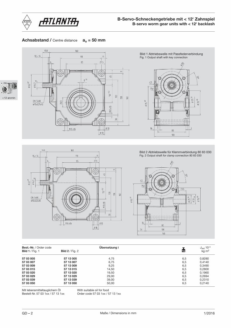
Achsabstand / Centre distance ao = 50 mm
B-Servo-Schneckengetriebe mit < 12' ZahnspielB-servo worm gear units with < 12' backlash
Best.-Nr. / Order code Übersetzung i Jred 10-4
Bild 1 / Fig. 1 Bild 2 / Fig. 2 kg m2
57 03 005 57 13 005 4,75 6,5 0,828057 03 007 57 13 007 6,75 6,5 0,414057 03 009 57 13 009 9,25 6,5 0,349057 03 015 57 13 015 14,50 6,5 0,280057 03 020 57 13 020 19,50 6,5 0,196057 03 029 57 13 029 29,00 6,5 0,269457 03 039 57 13 039 39,00 6,5 0,231057 03 050 57 13 050 50,00 6,5 0,2140
Mit lebensmitteltauglichem Öl With suitable oil for foodBestell-Nr. 57 03 1xx / 57 13 1xx Order code 57 03 1xx / 57 13 1xx
Bild 1 Abtriebswelle mit PassfederverbindungFig. 1 Output shaft with key connection
Bild 2 Abtriebswelle für Klemmverbindung 80 83 030Fig. 2 Output shaft for clamp connection 80 83 030
Maße / Dimensions in mm GD – 31/2016
< 12 arcmin
B-Servo-Schneckengetriebe mit < 12' ZahnspielB-servo worm gear units with < 12' backlash
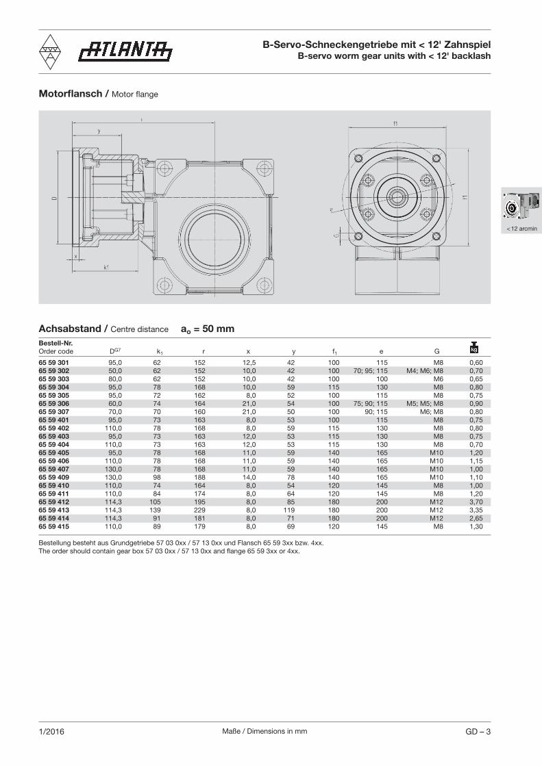
Motorflansch / Motor flange
Achsabstand / Centre distance ao = 50 mmBestell-Nr. Order code DG7 k1 r x y f1 e G
65 59 301 95,0 62 152 12,5 42 100 115 M8 0,6065 59 302 50,0 62 152 10,0 42 100 70; 95; 115 M4; M6; M8 0,7065 59 303 80,0 62 152 10,0 42 100 100 M6 0,6565 59 304 95,0 78 168 10,0 59 115 130 M8 0,8065 59 305 95,0 72 162 8,0 52 100 115 M8 0,7565 59 306 60,0 74 164 21,0 54 100 75; 90; 115 M5; M5; M8 0,9065 59 307 70,0 70 160 21,0 50 100 90; 115 M6; M8 0,8065 59 401 95,0 73 163 8,0 53 100 115 M8 0,7565 59 402 110,0 78 168 8,0 59 115 130 M8 0,8065 59 403 95,0 73 163 12,0 53 115 130 M8 0,7565 59 404 110,0 73 163 12,0 53 115 130 M8 0,7065 59 405 95,0 78 168 11,0 59 140 165 M10 1,2065 59 406 110,0 78 168 11,0 59 140 165 M10 1,1565 59 407 130,0 78 168 11,0 59 140 165 M10 1,0065 59 409 130,0 98 188 14,0 78 140 165 M10 1,1065 59 410 110,0 74 164 8,0 54 120 145 M8 1,0065 59 411 110,0 84 174 8,0 64 120 145 M8 1,2065 59 412 114,3 105 195 8,0 85 180 200 M12 3,7065 59 413 114,3 139 229 8,0 119 180 200 M12 3,3565 59 414 114,3 91 181 8,0 71 180 200 M12 2,6565 59 415 110,0 89 179 8,0 69 120 145 M8 1,30 Bestellung besteht aus Grundgetriebe 57 03 0xx / 57 13 0xx und Flansch 65 59 3xx bzw. 4xx. The order should contain gear box 57 03 0xx / 57 13 0xx and flange 65 59 3xx or 4xx.
Maße / Dimensions in mmGD – 4 1/2016
< 12 arcmin
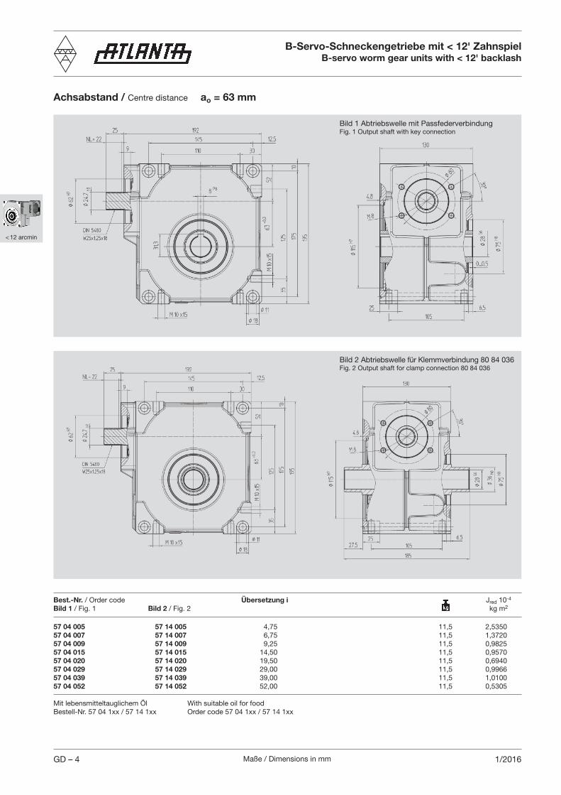
Achsabstand / Centre distance ao = 63 mm
B-Servo-Schneckengetriebe mit < 12' ZahnspielB-servo worm gear units with < 12' backlash
Bild 1 Abtriebswelle mit PassfederverbindungFig. 1 Output shaft with key connection
Bild 2 Abtriebswelle für Klemmverbindung 80 84 036Fig. 2 Output shaft for clamp connection 80 84 036
Best.-Nr. / Order code Übersetzung i Jred 10-4
Bild 1 / Fig. 1 Bild 2 / Fig. 2 kg m2
57 04 005 57 14 005 4,75 11,5 2,535057 04 007 57 14 007 6,75 11,5 1,372057 04 009 57 14 009 9,25 11,5 0,982557 04 015 57 14 015 14,50 11,5 0,957057 04 020 57 14 020 19,50 11,5 0,694057 04 029 57 14 029 29,00 11,5 0,996657 04 039 57 14 039 39,00 11,5 1,010057 04 052 57 14 052 52,00 11,5 0,5305
Mit lebensmitteltauglichem Öl With suitable oil for foodBestell-Nr. 57 04 1xx / 57 14 1xx Order code 57 04 1xx / 57 14 1xx
Maße / Dimensions in mm GD – 51/2016
< 12 arcmin
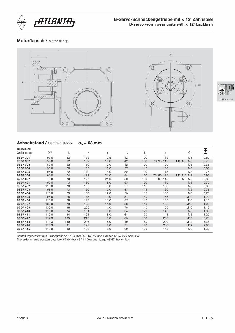
B-Servo-Schneckengetriebe mit < 12' ZahnspielB-servo worm gear units with < 12' backlash
Motorflansch / Motor flange
Bestell-Nr. Order code DG7 k1 r x y f1 e G
65 57 301 95,0 62 169 12,5 42 100 115 M8 0,6065 57 302 50,0 62 169 10,0 42 100 70; 95; 115 M4; M6; M8 0,7065 57 303 80,0 62 169 10,0 42 100 100 M6 0,6565 57 304 95,0 78 185 10,0 57 115 130 M8 0,8065 57 305 95,0 72 179 8,0 52 100 115 M8 0,7565 57 306 60,0 74 181 21,0 54 100 75; 90; 115 M5; M5; M8 0,9065 57 307 70,0 70 177 21,0 50 100 90; 115 M6; M8 0,8065 57 401 95,0 73 180 8,0 53 100 115 M8 0,7565 57 402 110,0 78 185 8,0 57 115 130 M8 0,8065 57 403 95,0 73 180 12,0 53 115 130 M8 0,7565 57 404 110,0 73 180 12,0 53 115 130 M8 0,7065 57 405 95,0 78 185 11,0 57 140 165 M10 1,2065 57 406 110,0 78 185 11,0 57 140 165 M10 1,1565 57 407 130,0 78 185 11,0 53 140 165 M10 1,0065 57 409 130,0 98 205 14,0 78 140 165 M10 1,1065 57 410 110,0 74 181 8,0 54 120 145 M8 1,0065 57 411 110,0 84 191 8,0 64 120 145 M8 1,2065 57 412 114,3 105 212 8,0 85 180 200 M12 3,7065 57 413 114,3 139 246 8,0 119 180 200 M12 3,3565 57 414 114,3 91 198 8,0 71 180 200 M12 2,6565 57 415 110,0 89 196 8,0 69 120 145 M8 1,30
Bestellung besteht aus Grundgetriebe 57 04 0xx / 57 14 0xx und Flansch 65 57 3xx bzw. 4xx.The order should contain gear box 57 04 0xx / 57 14 0xx and flange 65 57 3xx or 4xx.
Achsabstand / Centre distance ao = 63 mm
Maße / Dimensions in mmGD – 6 1/2016
< 12 arcmin
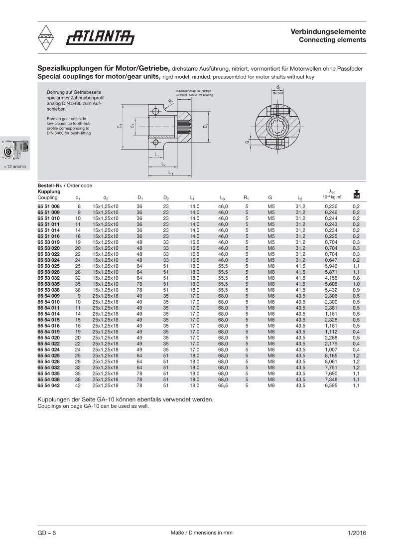
VerbindungselementeConnecting elements
Spezialkupplungen für Motor/Getriebe, drehstarre Ausführung, nitriert, vormontiert für Motorwellen ohne PassfederSpecial couplings for motor/gear units, rigid model, nitrided, preassembled for motor shafts without key
Bohrung auf Getriebeseitespielarmes Zahnnabenprofilanalog DIN 5480 zum Auf-schieben
Bore on gear unit side low-clearance tooth-hubprofile corresponding toDIN 5480 for push-fitting
Bestell-Nr. / Order codeKupplungCoupling d1 d2 D1 D2 L1 L3 R1 G L2
65 51 008 8 15x1,25x10 36 23 14,0 46,0 5 M5 31,2 0,236 0,265 51 009 9 15x1,25x10 36 23 14,0 46,0 5 M5 31,2 0,246 0,265 51 010 10 15x1,25x10 36 23 14,0 46,0 5 M5 31,2 0,244 0,265 51 011 11 15x1,25x10 36 23 14,0 46,0 5 M5 31,2 0,243 0,265 51 014 14 15x1,25x10 36 23 14,0 46,0 5 M5 31,2 0,234 0,265 51 016 16 15x1,25x10 36 23 14,0 46,0 5 M5 31,2 0,225 0,265 53 019 19 15x1,25x10 48 33 16,5 46,0 5 M5 31,2 0,704 0,365 53 020 20 15x1,25x10 48 33 16,5 46,0 5 M6 31,2 0,704 0,365 53 022 22 15x1,25x10 48 33 16,5 46,0 5 M5 31,2 0,704 0,365 53 024 24 15x1,25x10 48 33 16,5 46,0 5 M5 31,2 0,647 0,265 53 025 25 15x1,25x10 64 51 18,0 55,5 5 M8 41,5 5,946 1,165 53 028 28 15x1,25x10 64 51 18,0 55,5 5 M8 41,5 5,871 1,165 53 032 32 15x1,25x10 64 51 18,0 55,5 5 M8 41,5 4,158 0,865 53 035 35 15x1,25x10 78 51 18,0 55,5 5 M8 41,5 5,605 1,065 53 038 38 15x1,25x10 78 51 18,0 55,5 5 M8 41,5 5,432 0,965 54 009 9 25x1,25x18 49 35 17,0 68,0 5 M6 43,5 2,306 0,565 54 010 10 25x1,25x18 49 35 17,0 68,0 5 M6 43,5 2,300 0,565 54 011 11 25x1,25x18 49 35 17,0 68,0 5 M6 43,5 2,381 0,565 54 014 14 25x1,25x18 49 35 17,0 68,0 5 M6 43,5 1,161 0,565 54 015 15 25x1,25x18 49 35 17,0 68,0 5 M6 43,5 2,328 0,565 54 016 16 25x1,25x18 49 35 17,0 68,0 5 M6 43,5 1,161 0,565 54 019 19 25x1,25x18 49 35 17,0 68,0 5 M6 43,5 1,112 0,465 54 020 20 25x1,25x18 49 35 17,0 68,0 5 M6 43,5 2,268 0,565 54 022 22 25x1,25x18 49 35 17,0 68,0 5 M6 43,5 2,179 0,465 54 024 24 25x1,25x18 49 35 17,0 68,0 5 M6 43,5 1,007 0,465 54 025 25 25x1,25x18 64 51 18,0 68,0 5 M8 43,5 8,165 1,265 54 028 28 25x1,25x18 64 51 18,0 68,0 5 M8 43,5 8,061 1,265 54 032 32 25x1,25x18 64 51 18,0 68,0 5 M8 43,5 7,751 1,265 54 035 35 25x1,25x18 78 51 18,0 68,0 5 M8 43,5 7,690 1,165 54 038 38 25x1,25x18 78 51 18,0 68,0 5 M8 43,5 7,348 1,165 54 042 42 25x1,25x18 78 51 18,0 65,5 5 M8 43,5 6,595 1,1
Jred 10-4 kg m²
Kupplungen der Seite GA-10 können ebenfalls verwendet werden.Couplings on page GA-10 can be used as well.
Maße / Dimensions in mm GD – 71/2016
< 12 arcmin
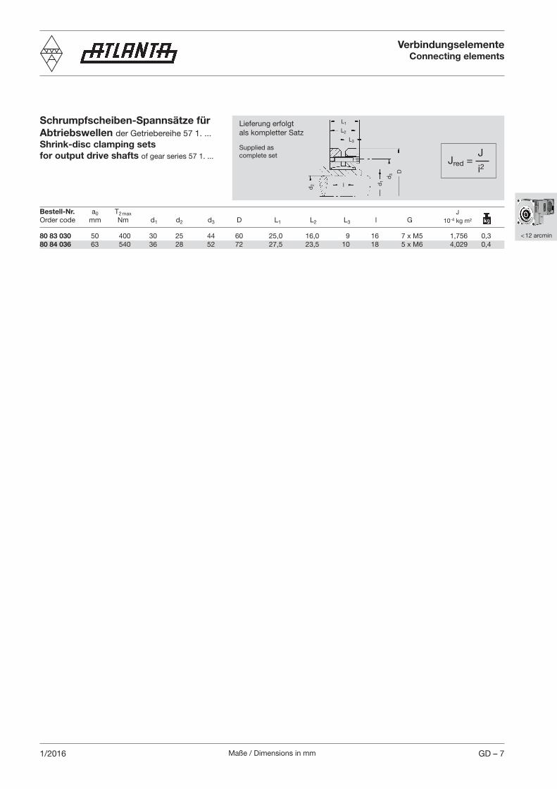
Jred =J
i2
Lieferung erfolgtals kompletter Satz
Supplied ascomplete set
d2 d
1
d3 D
L1
L2
L3
l
Schrumpfscheiben-Spannsätze für Abtriebswellen der Getriebereihe 57 1. ...Shrink-disc clamping sets for output drive shafts of gear series 57 1. ...
VerbindungselementeConnecting elements
80 83 030 50 400 30 25 44 60 25,0 16,0 9 16 7 x M5 1,756 0,380 84 036 63 540 36 28 52 72 27,5 23,5 10 18 5 x M6 4,029 0,4
J 10-4 kg m²
Bestell-Nr. a0 T2 max Order code mm Nm d1 d2 d3 D L1 L2 L3 l G
Maße / Dimensions in mmGD – 8 1/2016
< 12 arcmin
Auswahl- und Belastungstabellen für B-Servo-SchneckengetriebeSelection and load tables for B-servo worm gear units
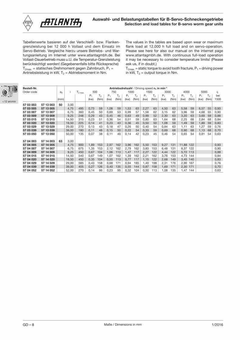
Bestell-Nr. Antriebsdrehzahl / Driving speed n1 in min-1 Order code a0 i T2 max. 500 750 1000 1500 3000 4000 5000 η P1 T2 P1 T2 P1 T2 P1 T2 P1 T2 P1 T2 P1 T2 bei (mm) (kw) (Nm) (kw) (Nm) (kw) (Nm) (kw) (Nm) (kw) (Nm) (kw) (Nm) (kw) (Nm) 1500
57 03 003 57 13 003 50 3,0057 03 005 57 13 005 4,75 495 0,73 59 1,08 59 1,53 63 2,27 63 4,50 63 5,58 59 6,57 55 0,9357 03 007 57 13 007 6,75 360 0,45 50 0,69 53 0,99 57 1,58 62 3,15 62 3,96 59 4,68 55 0,9057 03 009 57 13 009 9,25 248 0,29 43 0,45 46 0,63 49 0,99 52 2,30 63 3,20 63 3,69 59 0,8857 03 015 57 13 015 14,50 315 0,23 51 0,36 54 0,51 59 0,80 63 1,64 68 2,25 68 2,84 68 0,8457 03 020 57 13 020 19,50 225 0,14 41 0,23 43 0,36 45 0,50 50 1,08 59 1,49 59 1,89 59 0,8357 03 029 57 13 029 29,00 270 0,13 43 0,18 47 0,26 50 0,40 54 0,84 63 1,11 63 1,27 59 0,7657 03 039 57 13 039 39,00 180 0,11 48 0,15 50 0,22 54 0,33 59 0,69 68 0,90 68 1,13 68 0,7057 03 050 57 13 050 50,00 135 0,07 38 0,11 40 0,14 42 0,23 45 0,46 54 0,65 54 0,81 54 0,63
57 04 003 57 14 003 63 3,0057 04 005 57 14 005 4,75 900 1,89 153 2,97 162 3,96 162 5,50 153 9,27 131 11,88 122 0,9357 04 007 57 14 007 6,75 675 1,35 153 2,12 162 2,79 162 3,83 153 6,48 131 8,37 122 0,9057 04 009 57 14 009 9,25 450 0,67 104 1,06 113 1,47 117 2,27 122 4,44 122 5,72 113 0,8857 04 015 57 14 015 14,50 540 0,67 149 1,07 162 1,39 162 2,21 162 3,76 153 4,73 144 0,8457 04 020 57 14 020 19,50 450 0,35 104 0,55 113 0,77 117 1,15 122 2,68 149 3,45 140 0,8357 04 029 57 14 029 29,00 585 0,43 158 0,68 171 0,94 185 1,40 198 2,31 176 2,90 167 0,7657 04 039 57 14 039 39,00 405 0,27 126 0,40 135 0,55 144 0,87 158 1,69 171 2,30 171 0,7057 04 052 57 14 052 52,00 270 0,14 86 0,23 95 0,32 104 0,50 113 1,08 135 1,47 144 0,63
Tabellenwerte basieren auf der Verschleiß- bzw. Flanken-grenzleistung bei 12 000 h Vollast und dem Einsatz im Servo-Betrieb. Vergleiche hierzu unsere Betriebs- und War-tungsanleitung im Internet unter www.atlantagmbh.de. Bei Vollast-Dauerbetrieb muss u.U. die Temperatur-Grenzleistung berücksichtigt werden! (Gegebenenfalls bitte Rücksprache)T2max. = statisches Drehmoment gegen Zahnbruch, P1 = Antriebsleistung in kW, T2 = Abtriebsmoment in Nm.
The values in the tables are based upon wear or maximum flank load at 12,000 h full load and on servo-operation. Please see here for also our manual on the internet page www.atlantagmbh.de. With continuous full-load operation it may be necessary to consider temperature limits! (Please ask us, if in doubt.)T2max. = static torque to avoid tooth fracture, P1 = driving power in kW, T2 = output torque in Nm.
Maße / Dimensions in mm GD – 91/2016
< 12 arcmin
Auswahl- und Belastungstabellen für B-Servo-SchneckengetriebeSelection and load tables for B-servo worm gear units
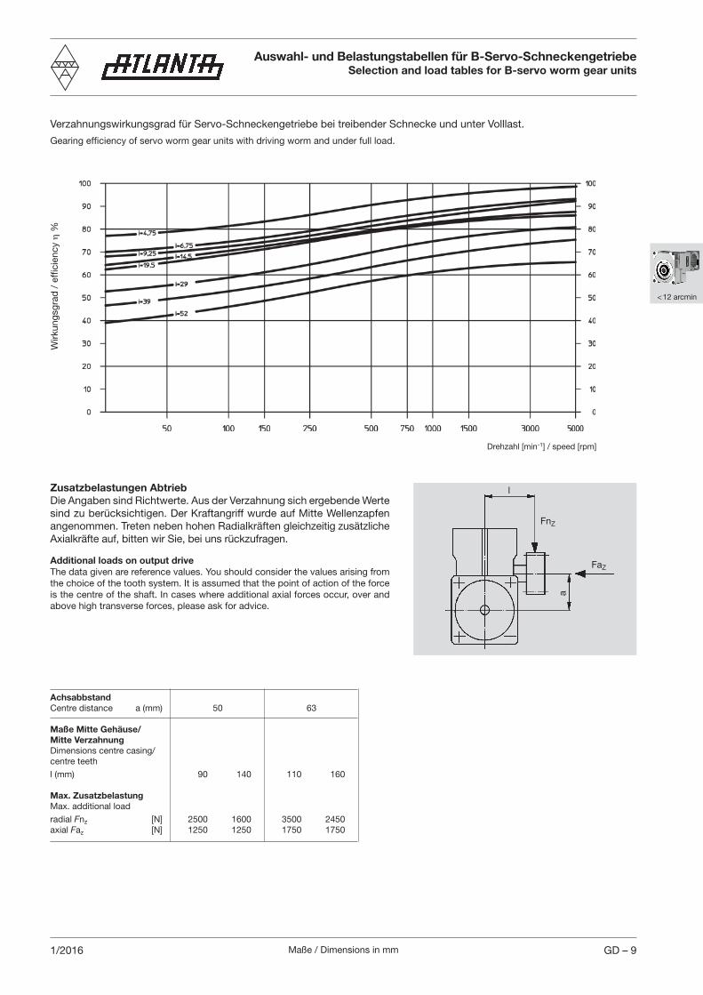
Verzahnungswirkungsgrad für Servo-Schneckengetriebe bei treibender Schnecke und unter Volllast.
Gearing efficiency of servo worm gear units with driving worm and under full load.
Wirk
ungs
grad
/ e
ffici
ency
η %
Zusatzbelastungen AbtriebDie Angaben sind Richtwerte. Aus der Verzahnung sich ergebende Werte sind zu berücksichtigen. Der Kraftangriff wurde auf Mitte Wellenzapfen angenommen. Treten neben hohen Radialkräften gleichzeitig zusätzliche Axialkräfte auf, bitten wir Sie, bei uns rückzufragen.
Additional loads on output driveThe data given are reference values. You should consider the values arising from the choice of the tooth system. It is assumed that the point of action of the force is the centre of the shaft. In cases where additional axial forces occur, over and above high transverse forces, please ask for advice.
l
FnZ
FaZa
AchsabbstandCentre distance a (mm) 50 63
Maße Mitte Gehäuse/Mitte VerzahnungDimensions centre casing/centre teeth
l (mm) 90 140 110 160
Max. ZusatzbelastungMax. additional load
radial Fnz [N] 2500 1600 3500 2450axial Faz [N] 1250 1250 1750 1750
Drehzahl [min-1] / speed [rpm]
Maße / Dimensions in mmGD – 10 1/2016
< 12 arcmin
B-Servo-SchneckengetriebeB-servo worm gear units
Kurzbeschreibung
ATLANTA-B-Servo-Schneckengetriebe sind speziell zum Einsatz mit Dreh- und Gleichstrom-Servomotoren der neuen Generation entwickelt worden. Sie sind, ebenso wie alle an-deren Artikel dieses Kataloges, in der Regel ab Lager bzw. kurzfristig lieferbar.
Folgende Merkmale zeichnen unsere B-Servo-Getriebe aus:
• gleiche Abmessungen wie unsere bewährten Servo- Getriebe der 59 Reihe• spielarme Verzahnung (Spiel < 12')• Gehäuse aus Leichtmetall für optimale Wärmeabfuhr• robuste Lagerung der Abtriebs-Hohlwelle für Zusatzkräfte
Bei den Achsabständen, den Übersetzungen und den Verzah-nungen haben wir uns an DIN 3975/76 orientiert. Der Einsatz geschliffener, rechtssteigender Schnecken, eines Schnecken-rades aus Spezial-Schneckenradbronze in Verbindung mit einer Tauchschmierung (synthetisches Spezialöl) gewährleistet neben einem hohen Wirkungsgrad einen ruhigen Lauf in bei den Drehrichtungen und eine lange Lebensdauer. Das Ge häuse mit seinen vielen Befestigungs- und Gewindebohrungen erlaubt die Montage in jeder beliebigen Einbaulage.
Der Antrieb bzw. die Verbindung mit dem Antriebsmotor erfolgt durch eine Spezialkupplung, deren Innenverzahnung, zusammen mit der längsballig verzahnten Antriebswelle unserer Schneckengetriebe, einen spielfreien Kraftfluss gewährleistet.
Für den Abtrieb steht eine ganze Reihe von Abtriebswellen mit Gerad- und Schrägverzahnung, jeweils mit verschiedenen Zähnezahlen, zur Verfügung. Neben verzahnten Ritzelwellen kann darüber hinaus eine Vielzahl von weiteren Zähnezahlen aus unserem S & L-Zahnradprogramm mit passenden Spezial-Abtriebswellen kombiniert und eingesetzt werden.
Für Not-Stopp sind die maximal übertragbaren Drehmomente des Getriebes gegen Zahnbruch (siehe Seite GD-8) und der Schrumpfscheibe (siehe Seite GH-1) zu beachten. Eine Pass federverbindung am Abtrieb muss separat nach ge-rechnet werden.
Short description
ATLANTA B-servo worm gear units have been specially developed for use with the latest three-phase and DC servo-motors. Like all other components in this catalogue, they are usually available ex stock or, at least, within a very short time.
The following are typical features of our B-servo gear units:
• the same dimensions as our servo worm gear units serie 59• low-clearance gearing (back lash < 12'), • casing of light metal for optimal heat dissipation• robust bearings for the output drive hollow shaft, permitting additional forces.
Centre distances, gear ratios and tooth systems have been chosen in accordance with DIN 3975/76.
The use of ground, right-hand worms, a worm gear of special worm-gear bronze and dip-feed lubrication (synthetic special oil) ensures a high degree of efficiency and also smooth run-ning in both directions and a long service life. The casing with its many fixing bores and tapped holes permits mounting in any position.
The drive, i.e. the connection with the driving motor, is achie-ved with a special clutch. Its internal gearing, together with the barrelled profile of the driving shaft of our worm gear unit ensures transmission of the power with no free play.
For the output drive you can choose from quite a number of output drive shafts with straight and helical tooth systems and various numbers of teeth. Apart from toothed pinion shafts the-re is a multitude of gearwheels with different numbers of teeth from our S & L gearwheel program which can be combined and used together with suitable special output drive shafts.
For safety-stop is the maximum transmittable torque of the gear unit (see page GD-8) and shrink disc (see page GH-1) has to be checked. The output keyway has to be calculated separately.
Maße / Dimensions in mm GD – 111/2016
< 12 arcmin
Einbau, Wartung und Ersatzteile für B-Servo-Schneckengetriebe Mounting, maintenance and spare parts for B-servo worm gear units
MontageanleitungSchneckengetriebeEs stehen 5 bearbeitete Anbauflächen mit ausreichend di-mensionierten Befestigung- und Gewindebohrungen für eine verspannungsfreie Montage in allen Einbaulagen zur Verfü-gung. Bei voller Ausnutzung der Zusatzkräfte (s. Seite GD-9) empfehlen wir die Montage an den größten Anlageflächen, d.h. an einer der beiden Deckelseiten vorzunehmen. Die günstigste Einbaulage für die Schmierung wird bei seitlicher bzw. untenliegender Schneckenwelle (Eintriebswelle) erreicht. Bei obenliegender Welle ist zu beachten, dass sich dadurch die Antriebsleistung um ca. 10 % vermindert.
KupplungDie Kupplung wird vormontiert geliefert. Vor Befestigung auf der Motorwelle müssen sämtliche Kontaktflächen sauber gereinigt und durch leichten Ölfilm geschützt sein. Für die Montage ist das Maß „X1“ wichtig (vergleiche Seiten GI – 5 bis GI – 9). Empfohlener Arbeitsablauf:– Kontaktflächen sauber reinigen und durch leichten Ölfilm
schützen– Kupplung im Abstand des Maß „X1“ (vergleiche Seiten GI – 5
bis GI – 9) auf die Motorwelle aufsetzen, zur Ermittlung des Maßes ist ein Tiefenmaß hilfreich
– Spannschrauben leicht anziehen und Kupplung auf Rundlauf prüfen
– Schrauben abwechselnd gleichmäßig anziehen– Anzugsmoment lt. Betriebs- und Wartungsanleitung einhal-
ten und hierbei beachten, dass der Spalt in der Kupplung auf beiden Seiten gleich breit bleibt
– Eine nochmalige, abschließende Rundlaufkontrolle am dafür vorgesehenen Prüfbund ist zu empfehlen!
Einen Montageführer finden Sie auf der Seite GI-5 bis GI-9.
Motormit montierter Kupplung in die Getriebezentrierung einschie-ben und mit Getriebegehäuse verschrauben.
Abtriebs-(Ritzel)WelleSofern die Abtriebs-(Ritzel)welle nicht bereits bei der Lieferung montiert ist, empfehlen wir folgenden Arbeitsablauf:Abtriebs-(Ritzel)welle und Getriebe-Abtriebshohlwelle säubern und anschließend ölen. Für Sonderabtriebswellen empfehlen wir die Toleanz h6 (DIN ISO 286). Das Material muss eine Mindest-streckgrenze von 385 N/mm2 aufweisen. Eine Nachrechnung der Festigkeit muss aber dennoch erfolgen.
Abtriebswelle für Schrumpfscheiben-VerbindungSchrumpf scheibe auf Getriebe-Hohlwelle aufschieben (Schrauben vorher bitte nicht anziehen!). Abtriebswelle von der gewünschten Seite bis auf Anschlag in die Hohlwelle einschieben. Herstellen der Querpressverbindung durch gleichmäßiges Anziehen der Spannschrauben. Schrauben der Reihe nach in mehreren Umläufen auf Drehmoment nach Betriebs- und Wartungsanleitung anziehen (nicht überkreuz).
Abtriebswelle für Passfeder-VerbindungDer mit der Abtriebswelle mitgelieferte Sicherungsring, die Scheibe und Schraube dienen der axialen Befestigung der Abtriebswelle. Dazu wird der Sicherungsring in den ent-sprechenden Einstich der Getriebe-Hohlwelle montiert, die Abtriebswelle von der gewünschten Seite bis auf Anschlag in die Hohlwelle eingeschoben. Die Scheibe und Schraube werden von der anderen Getriebeseite mit der Abtriebswelle verschraubt. Der Sicher ungs ring muss zwischen Scheibe und Ritzelwelle eingespannt sein.
Mounting instructionsWorm gear unitsFive mounting faces with sufficiently dimensioned tapped holes are provided for mounting in any position. In order to accommodate all supplementary forces (see page GD-9) we recommend mounting at the largest contact faces., i.e. at one of the two cap sides. Putting the worm shaft (input shaft) in a lateral or inferior position is ideal for lubrication. Mounting the shaft in a top position will reduce the driving capacity by about 10 %.
CouplingThe coupling is supplied pre-assembled. All contact sur-faces must be cleaned and protected by a thin oil film before attaching it to the motor shaft. An important dimension for mounting is the value „X1” (compare pages GI – 5 to GI – 9). Recommended procedure: – Carefully clean the contact surfaces and protect them with
a thin oil film.– Place the coupling onto the motor shaft at the distance given
by the measurement “X1” (see pages GI – 5 to GI – 9); a depth gauge is helpful for determining the measurement.
– Slightly tighten the clamping screws and check the clutch for true running
– Tighten the screws alternately and uniformly. – The correct tightening torque can be seen from the operation
and maintenance instructions. The gap in the coupling must be equally wide on both sides.
– It is recommended to make another final check for true run-ning at the appropriate reference diameter!
A mounting guide can be found on page GI-5 to GI-9.
MotorInsert the motor with coupling mounted into the gear centering piece and bolt it to the gearbox.
Output drive (pinion) shaftUnless the output pinion shaft comes already fully assembled, we recommend to proceed as follows:Clean pinion shaft and hollow shaft extension and then oil them. For the special output drive shaft we recommend to-lerance h6 (DIN ISO286). the material must have a minimum yield point of 385 N/mm². A recalculation of the strength is necessary.
Output drive shaft for shrink-disc connec tionSlide shrink disc onto the hollow shaft extension of the gear unit (please do not tighten the screws beforehand!).Insert the output shaft from the desired side into the hollow shaft fully up to the stop. Make the transverse pressure connection by evenly tightening the clamping screws. Tighten the screws one after the other (not crosswise) in several passes to the torque indicated in the operation and maintenance instructions.
Output drive shaft for key connectionThe retaining ring, the disc and the screw supplied with the output drive shaft serve for locking the output shaft in axial direction. For this purpose insert the retaining ring in the ap-plicable recess of the hollow shaft and slide the output drive shaft from the desired side into the hollow shaft up to the stop. Disc and screw are screwed to the output shaft from the other side of the gear unit. The retaining ring must be clamped between disc and pinion shaft.
Maße / Dimensions in mmGD – 12 1/2016
< 12 arcmin
Wartung
SchmierstoffwechselATLANTA B-Servo-Schneckengetriebe sind mit synthetischem Polyglykol-Öl befüllt.Dies ist unter folgenden Voraussetzungen eine Lebensdau-erschmierung:Die Auslegung des Getriebes erfolgte ausschließlich nach den im ATLANTA-Katalog vorgegebenen Richtlinien und das Ge-triebe wird ausschließlich innerhalb der zulässigen Kenn- und Grenzwerte betrieben. Der Betreiber kontrolliert das Getriebe regelmäßig (alle 4 Wochen) auf Ölverlust. Oberflächentempe-ratur max. 80 °C. Bei Servo-Betrieb (Aussetzbetrieb) wird diese Temperatur erfahrungsgemäß nicht erreicht.Bei einem Betrieb mit überwiegend kleinen Eintriebsdreh-zahlen (Umfangsgeschwindigkeit der Schnecke v < 0,5 m/s) empfehlen wir einen Schmierstoffwechsel im zweijährigen Turnus.
Wir empfehlen folgenden synthetischen Ge triebe schmierstoff:Klübersynth GH 6 - 220 Bestell-Nr. 65 90 010 (1 Liter)
alternativ:SHELL Tivela S 220, BP Enersyn SG-XP 220, ARAL Degol GS 220
SchutzartSchutzart: IP65/67 in Anlehnung an ISO 20653 (Schutz gegen Korrosion muss gesondert betrachtet werden).
Maintenance
Lubricant changeATLANTA B-servo-assisted worm-gear units are filled with synthetic polyglycol oil.Under the following conditions this is a lifetime lubrication:The layout of the gear unit is made strictly in conformance with the guidelines specified in the ATLANTA catalogue and the gear unit is operated exclusively within the permissible characteristic values and limits. The operator checks the gear unit regularly (every 4 weeks) for oil leakage. The surface tem-perature does not exceed max. 80° C. Experience has shown that this temperature is not reached with servo-operation (intermittent operation). In the case of an operation with mainly low input speeds (cir-cumferential speed of the worm v < 0.5 m/s) we recommend to change the lubricant every two years.
We recommend the following synthetic gear lubricant:Klübersynth GH 6 - 220Order code: 65 90 010 (1 litre)
alternative:SHELL Tivela S 220, BP Enersyn SG-XP 220, ARAL Degol GS 220
Degree of protectionDegree of protection: IP65/67 according to ISO 20653 (Corrosion has to be verified separately).
Achsabstand Ölmenge Centre distance Oil quantity
a = 50 mm 0,25 la = 63 mm 0,60 l
Einbau, Wartung und Ersatzteile für B-Servo-Schneckengetriebe Mounting, maintenance and spare parts for B-servo worm gear units