Embed Size (px)
Citation preview
Kraftfahrt-Bundesamt DE-24932 Flensburg
Bestätigung des Kraftfahrt-Bundesamt für
Confirmation by the Kraftfahrt-Bundesamt with respect to
X
ein Prüfprotokoll für Antiblockiervorrichtungen (ABV) für Anhänger nach der UNECE-Regelung Nr. 13, Anhang 19-Anlage 6, Nr.6. a trailer anti-lock braking system test report according to UNECE-Regulation No. 13 Annex 19, Appendix 6, No. 6.
X
einen Typgenehmigungsbericht für ABV-Bremsanlagen von Anhängern nach der Richtlinie 71/320/EWG, Anhang XIV-Anlage 1, Nr. 5. a trailer anti-lock braking system approval report to Directive 71/320/EEC, Annex XIV, Appendix 1, No. 5.
Das System, beschrieben im anliegenden Technischen Bericht – The system
described in the Technical Report attached
Prüfprotokoll Nr.: EB 123.10E Test report No.
vom 09.09.2011 dated
Hersteller: Manufacturer
: WABCO Fahrzeugsysteme GmbH
Bezeichnung des Systems: Trailer EBS (Variant E) System name
entspricht nach Aussage der - is, according to a statement issued by:
TÜV Nord Mobilität GmbH & Co.KG
DE-30519 Hannover und / and DE-45307 Essen den Anforderungen an die speziellen Vorschriften für Anhänger gemäß der ECE-
Regelung Nr. 13 einschließlich Änderungsserie 11 und Richtlinie 71/320/EWG. (in accordance with the special requirements for trailer vehicles according to ECE-Regulation No. 13, series of Amendments 11 and Directive 71/320/EEC.
Hinsichtlich des Verwendungsbereichs und der Ein- bzw. Anbauvorschriften wird auf die Festlegungen im oben genannten Technischen Bericht hingewiesen. (For details to the range of use and the installation or mounting regulations consult the aforementioned Technical Report.)
Kraftfahrt-Bundesamt DE-24932 Flensburg
2
Bestätigung: Die TÜV NORD MOBILITÄT GmbH & Co. KG ist vom Kraftfahrt-Bundesamt als Prüflaboratorium für Bremsanlagen nach der EG-Richtlinie 71/320/EWG und der ECE Regelung Nr. 13 akkreditiert und unter der KBA-P 00004-96 registriert. Confirmation: TÜV Nord Mobilität GmbH & Co. KG is accredited by the German Federal Motor Transport Authority as a Testing Laboratory for braking systems according to Directive 71/320/EEC and ECE Regulation No. 13 and is registered under the No. KBA-P 00004-96.
Anlagen: 1 Technischer Bericht Nr.: EB 123.10E (Annex) 1 Technical Report No.: EB 123.10E
Ort - Place:
DE-24932 Flensburg
Datum - Date:
23.09.2011
Unterschrift: Signature:
Im Auftrag
(Stegemann)
EB123-10E.DOC
Mobi l i tä t
TÜV NORD Mobi l i tä t GmbH & Co. KG
IFM – Institute for Vehicle Technology and Mobility
Adlerstraße 7
45307 Essen
Tel.: +49 (0)201 825-4120
Fax: +49 (0)201 825-4150
www.tuev-nord.de
Corporate seat: Hannover
Commercial Register section
HRA 27006
Management:
Dr. Klaus Kleinherbers
TRAILER ANTI-LOCK BRAKING
SYSTEM APPROVAL REPORT
A p p r o v a l R e p o r t N o : E B 1 2 3 . 1 0 E
ECE Regulation No. 13 - Annex 19
Directive 71/320/EEC - Annex XIV
0. General
With respect to the previous TÜV NORD Report EB123.9E this report covers the following additions:
- Category B configurations, see also paragraph 2.1.2 below
- ABS configurations for braking systems for inloader (special trailers with U-frame to transport e.g. glass or concrete panels); see also paragraph 2.1.3 below and paragraph 3.6.2 of ID_TEBS
- Additional suspension types (Appendix 2 of ID_TEBS)
- Editorial amendments
For the sake of simplicity the Manufacturer’s Information Docu-ment “ID_EB123.9E” of the Trailer EBS E system is abbreviated to I D _ T E B S .
1. Identification
1.1 Manufacturer: WABCO Fahrzeugsysteme GmbH Am Lindener Hafen 21 D - 30453 Hannover
1.2 System name/model: Trailer EBS
1.3 System variant: E (see also paragraph 1.3 of ID_TEBS)
Versions: - Trailer EBS E
- Trailer EBS E with TCE*
* TCE: Trai ler Central Electronic
Note: Regarding the description of the above mentioned different versions see paragraphs 1.3 and 3.2 of ID_TEBS.
A p p r o v a l R e p o r t N o . E B 1 2 3 . 1 0 E
Manufacturer: WABCO
ABS-System: Trailer EBS (E) p a g e 2 / 1 2
EB123-10E.DOC
2. System and installation
2.1 Configurations
a) Standard configurations: see Appendix 1a of ID_TEBS
2S/2M - 2S/2M+SLV - 4S/2M - 4S/2M+1M - 4S/3M
b) Category B configurations: see Appendix 1b of ID_TEBS
2S/1M
see also paragraph 2.1.2 below
c) Inloader configurations: see Appendix 1c of ID_TEBS
2S/2M_SRV - 2S/2M_DRV - 4S/2M_SRV
see also paragraph 2.1.3 below
2.1.1 Category A performance: All anti-lock system configurations and installations de-fined in appendices 1a and 1c of ID_TEBS comply with the prescribed split friction requirements defined in para-graph 6.3.2 of annex X to Directive 71/320/EEC and An-nex 13 to ECE-Regulation No. 13.
2.1.2 Category B anti-lock performance (O3 trailers): The anti-lock system configurations 2S/1M contained in
Appendix 1b of the ID_TEBS do not comply with the pre-scribed split friction requirements defined in paragraph 6.3.2 of Annex X. 6 to Directive 71/320/EEC and Annex 13 to ECE-Regulation No. 13. However, all relevant pro-visions applicable to this ABS category are fulfilled, see also paragraph 1 of Appendix 6 of this report.
2.1.3 “Inloader” configurations: For special vehicles where it is not possible to place the
modulator in the vicinity of the brake chambers it is neces-sary to use comparatively long pipe length as opposed to conventional braking systems. In order to improve the re-sponse behaviour of the anti-lock braking system the “inloader” configurations (see Appendix 1c of ID_TEBS) include relay valves; see also Appendix 4, paragraph 1 of this report (system configurations). In paragraph 5.3.6 of Annex 13, ECE-R13, it is stipulated that brief periods of wheel-locking are allowed.
A p p r o v a l R e p o r t N o . E B 1 2 3 . 1 0 E
Manufacturer: WABCO
ABS-System: Trailer EBS (E) p a g e 3 / 1 2
EB123-10E.DOC
For conventional braking system times of 0.1 s (on high adhesion surfaces) and 0.5 s (on low adhesion surfaces) are seen as acceptable brief periods of wheel locking.
However, in the case of “inloader” configurations espe-cially at first application of the brakes and at vehicles speeds below 50 km/h wheel locking occurred also for pe-riods up to 300 ms without losing stability (see also obser-ved wheel locking times recorded in Appendix 4-4 “Addi-tional checks” of this report).
For inloaders (special trailers with U-frame to transport e.g. glass or concrete panels, see also paragraph 3.6.2 of ID_TEBS) where it is not technically possible to place the modulator near the brake chambers this periods of wheel locking are regarded as “brief”. Thus, these configurations are only seen as acceptable for these kind of special vehi-cles as no better technical solution seems to be available at the time being.
2.2. Range of application
2.2.1 Standard configurations: see Appendix 1a of ID_TEBS
All standard system configurations may be used on semi- or centre-axle trailers having up to 3 axles.
4S/3M configurations may be used on full trailers with either 2 or 3 axles.
For specific applications refer to section 2 and Appen-dix 1a of ID_TEBS.
For more detailed system installation examples refer to paragraph 3.5 and Appendix 4 of ID_TEBS.
2.2.2 Category B configurations: see Appendix 1b of ID_TEBS
System configurations may be used
- on semi- or centre-axle trailers having up to 2 axles
- for trailers with more than 3 axles which utilize this Annex 19 test report in order to apply the procedure as laid down in ECE R13, Annex 20, paragraph 7.4.
A p p r o v a l R e p o r t N o . E B 1 2 3 . 1 0 E
Manufacturer: WABCO
ABS-System: Trailer EBS (E) p a g e 4 / 1 2
EB123-10E.DOC
2.2.3 Inloader configurations: see Appendix 1c of ID_TEBS
These configurations may be used only on special 2- and 3-axle semi-trailer trailers (as described in paragraph 2.1.3).
2.3 Methods of powering: All system configurations have the ability to accept a con-tinuous power supply via the prescribed special connector conforming to ISO 7638 and - as a back up - an intermit-tent power supply via the ISO 1185 (24N) or ISO 12098 connector (stop lamp circuit).
Permanent To comply with the requirements of Directive 71/320/EEC and ECE Regulation 13 full functionality of the system can only be obtained when connected to an interface con-forming to the following standards:
ISO 7638:1985 (24 V) 5 Pin (71/320/EEC)
ISO 7638:2003 Part 1 (24 V) 5 Pin
ISO 7638:2003 Part 1 (24 V) 7 Pin
Note: The system is also compatible with connectors pro-duced in accordance with ISO 7638:1997
Intermittent: As a safety function in the event of a failure of the perma-nent ISO 7638 electrical power supply the system is able to receive intermittently electrical power from the ISO 1185 (24N) or ISO 12098 connector (stop lamp cir-cuit). In this case only the anti-lock braking and the load-dependent brake force controls are available.
For more detailed information see ID_TEBS, paragraphs 1.5 and 3.4.
2.4 Identification of approved components
2.4.1 Wheel speed sensors: see paragraph 3.1 of ID_TEBS 2.4.2 Controller: see paragraph 3.2 of ID_TEBS
A p p r o v a l R e p o r t N o . E B 1 2 3 . 1 0 E
Manufacturer: WABCO
ABS-System: Trailer EBS (E) p a g e 5 / 1 2
EB123-10E.DOC
2.4.3 Modulators: see paragraph 3.3 of ID_TEBS
The part numbers not fully specified in ID_TEBS indicate that deviations from the listed equipment/components are possible. These, however, have no influence on the func-tions and effect with regard to the inspection performed.
2.5 Energy consumption
2.5.1 Drum brakes
- except “inloader” configurations, see paragraphs 2.1c) and 2.1.3 above
2.5.1.1 Equivalent static brake applications:
Semi-trailers: ne_EC = 11 applications
ne_ECE = 13 applications
Full trailers: ne_EC = 11 applications
ne_ECE = 13 applications
Notes :
The values ne_EC above is to be used with the verification procedure defined within annex XIV, paragraph 6.2 of Di-rective 71/320/EEC.
The values ne_ECE above is to be used with the verification procedure defined within annex 20, paragraph 7.3 of ECE-Regulation No. 13.
2.5.1.2 Ratio of actuator stroke
against brake lever length: R = sT / lT = 0.2 (in all cases)
A p p r o v a l R e p o r t N o . E B 1 2 3 . 1 0 E
Manufacturer: WABCO
ABS-System: Trailer EBS (E) p a g e 6 / 1 2
EB123-10E.DOC
2.5.2 Disc brakes: Annex XIV of Directive 71/320/EEC only defines a test procedure for trailers with drum brakes but states that al-ternative designs may be taken into consideration. In the case of disc brakes it is not possible to manipulate the stroke/pressure relationship due to the integration of auto-matic wear adjustment. To establish an alternative proce-dure, comparative testing was carried out with an unmodi-fied installation and an installation with a 20 % increase in delivery volume. This simulated a condition of R x 1,2 so that the equivalent number of static brake applications could be defined for the increased volume condition. This value is defined below as ne_EC.
2.5.2.1 Equivalent static brake applications:
Semi-trailers: except “inloader” configurations, see also paragraphs 2.1c) and 2.1.3 above
ne_EC = 11 applications
ne_ECE = 12 applications
Semi-trailers: “inloader” configurations
ne_EC = 12 applications
ne_ECE = 13 applications
Note: The energy consumptions test were carried out with test trailers having a brake air reservoir of 160 l (see test results in paragraph 1 of Appendix 4-2 of this report).
Full trailers: except “inloader” configurations, see also paragraphs 2.1c) and 2.1.3 above
ne_EC = 11 applications
ne_ECE = 12 applications

A p p r o v a l R e p o r t N o . E B 1 2 3 . 1 0 E
Manufacturer: WABCO
ABS-System: Trailer EBS (E) p a g e 7 / 1 2
EB123-10E.DOC
Notes:
- The brake applications ne_EC defined above already take account of an increase in delivery volume of 20 %. There-fore, only in the case of trailers equipped with disc brakes, the procedure defined in paragraph 6.2.1.2 of Annex XIV of Directive 71/320/EEC is to be carried out without any in-crease in actuator stroke as defined in paragraph 6.2.1.1 of Annex XIV.
The values ne_ECE above is to be used with the verifica-tion procedure defined within annex 20, paragraph 7.3 of ECE-Regulation No. 13.
2.6 Additional features: The following additional features are provided as options. They are not subject to the assessment of this re-port.
2.6.1 Load-dependent brake force control (LSV): see ID_TEBS, paragraph 1.5.1.1.2
2.6.2 Monitoring of brake air pressure: see ID_TEBS, paragraph 1.5.1.1.7
2.6.3 Lifting axle control: see ID_TEBS, paragraph 1.5.1.1.8
2.6.4 Integrated speed switch: see ID_TEBS, paragraph 1.5.1.1.9
2.6.5 Standstill function: see ID_TEBS, paragraph 1.5.1.1.5
2.6.6 Emergency braking function: see ID_TEBS, paragraph 1.5.1.1.6
2.6.7 Roll Stability Support (RSS): see ID_TEBS, paragraph 1.5.1.1.11
2.6.8 ECAS: see ID_TEBS, paragraph 1.5.1.1.12
2.6.9 Parameter setting: see ID_TEBS, paragraph 1.5.1.1.13
3. Test data and results
3.0 General
3.1. Test vehicle data: see Appendix 3 of this approval report
3.2. Test surface information: see Appendix 2 of this approval report
A p p r o v a l R e p o r t N o . E B 1 2 3 . 1 0 E
Manufacturer: WABCO
ABS-System: Trailer EBS (E) p a g e 8 / 1 2
EB123-10E.DOC
3.3. Test results
3.3.1. Utilisation of adhesion: see Appendix 4-1 of this approval report
Note : Annex 19, paragraph 5.3.1.4 stipulates: “... The utilization of adhesion shall be determined with the load sensing valve set to laden and unladen conditions....”
This paragraph 5.3.1.4 is commonly interpreted that the ε-value has only to be determined with a LSV when the trailer braking system incorporates actually such a valve. The Trailer EBS variant E incorporates a “load-dependent brake force control” (see paragraph 1.5.1.1.2 of ID_TEBS) which shows the “laden/unladen” brake pressure charac-teristic. However, at full brake application the emergency braking function (see paragraph 1.5.1.1.6 of ID_TEBS) is activated. Therefore, during ABS testing, independent of the load condition, the “laden” pressure characteristic is used.
3.3.2. Energy consumption
3.3.2.1 Worst case axle load: see paragraph 2.7 of ID_TEBS.
3.3.2.2 Test results: see Appendix 4-2 of this approval report
3.3.3. Split-friction test: see Appendix 4-3 of this approval report
3.3.4. Low speed performance: see Appendix 4-4, paragraph 1 of this approval report
3.3.5. High speed performance: see Appendix 4-4, paragraph 2 of this approval report
3.3.6. Additional checks
3.3.6.1 Transition from high to low-adhesion surfaces: see Appendix 4-4, paragraph 3 of this approval report
3.3.6.2 Transition from low to high-adhesion surfaces: see Appendix 4-4, paragraph 4 of this approval report
3.3.7 System safety assessment/ failure mode simulation: The assessment and simulation was carried out following
the procedure defined within Annex 18 to ECE-Regulation No. 13. The results from this assessment are reported in TÜV NORD Test Report EB 124.4E (see Annex 1 “Elec-tronic Function & Safety”).
A p p r o v a l R e p o r t N o . E B 1 2 3 . 1 0 E
Manufacturer: WABCO
ABS-System: Trailer EBS (E) p a g e 9 / 1 2
EB123-10E.DOC
3.3.8. Functional checks of optional power connections: A failure of the ISO 7638 power supply was simulated by
disconnecting the connector. In this case the anti-lock braking function and load dependent pressure control re-mains operational when the system is wired to the stop lamp supply of either the ISO 1185 or ISO 12098 connec-tions. This mode of operation is intended to enhance the failure modes of the braking system in the event of a fail-ure of the ISO 7638 power supply occurs in service and is not a means of powering the braking system when no power supply failure exists (see also paragraph 2.3 of this report and paragraphs 1.5.1 c) and 3.4 of ID_TEBS).
3.3.9 Electromagnetic compatibility: The system has been tested and verified to conform to the requirements of Directive 72/245/EEC as last amended by Directive 2006/28/EC* . A copy of the approval report is included in ID_TEBS (see paragraph 3.6 and Appendix 6 of that document).
* Note: This approval does not make reference to ECE-Regula-tion 10. However, the performance requirements of Di-rective 72/245/EEC as last amended by Directive 2006/28/EC are more extensive than those of ECE-Regulation 10/02. Since Directive 72/245/EEC contains also all technical requirements of ECE-Regulation 10/02 compliance with ECE-Regulation 10/02 is as-sured as well.
3.3.10 ADR regulations: Within the test procedure according to Annex XIV and Annex 19 resp. no assessment was performed against ADR (Regulation governing Road Transport of Hazardous Goods). For information, see WABCO statement in the Manufacturer’s Information Document, paragraph 3.4.
4. Limitations of installation
4.1. Tyre to exciter relationship: The relationship of tyre circumference to the resolution of the exciter is defined in ID_TEBS, paragraph 2.3.
4.2. Tyre size tolerance: The permissible tolerance on tyre circumference between one axle and another fitted with the same exciter is defined in ID_TEBS, paragraph 2.4, see also Appendix 5, paragraph 1 to this approval report.
A p p r o v a l R e p o r t N o . E B 1 2 3 . 1 0 E
Manufacturer: WABCO
ABS-System: Trailer EBS (E) p a g e 1 0 / 1 2
EB123-10E.DOC
4.3. Suspension type: System performance was verified on trailers with balanced pneumatic and mechanical suspensions. Paragraph 2.5 and Appendix 2 of ID_TEBS defines approved suspensions for the purpose of the application of this approval.
In the case semi-trailers the measured braking perform-ances refer to vehicle combinations where the coupling heights (fifth wheel) of the tractor and trailer where of a similar height, thus leading to equal static loads among the trailer axles (no or almost no longitudinal inclination of the trailer chassis).
4.4. Differential(s) in brake input
torque within a trailer bogie: - permissible on all system configurations except “inloader” configurations, see paragraphs 2.1c) and 2.1.3 above
see also paragraph 2.6 of ID_TEBS and Appendix 5, paragraph 2 to this approval report
4.5. Wheel base of full trailer
4.5.1 Two axle full trailers: The wheel base is defined as the distance between centre line of axle 1 and the centre line of axle 2. The minimum approved wheel base being 3000 mm.
4.5.2 Three axle full trailers: The wheel base is defined as the distance between centre line of axle 1 and the centre between the wheels of axles 2 and 3. The minimum approved wheel base being 3745 mm.
4.6. Brake type: The anti-lock system configurations covered by this ap-proval are deemed to be satisfactory for trailers equipped with either air operated drum or disc brakes.
4.7. Tube sizes and lengths: see paragraphs 3.5 and 3.6 of ID_TEBS and Appendix 5, paragraph 2 to this approval report
Note: The use of the tube sizes recommended does not guarantee that the prescribed brake system response time can be fulfilled, therefore it shall be demonstrated that this requirement is fulfilled for each installation.
4.7.1 Standard configurations and Category B configurations: according to appendices 1a and 1b of ID_TEBS
see paragraph 3.6.1 of ID_TEBS
A p p r o v a l R e p o r t N o . E B 1 2 3 . 1 0 E
Manufacturer: WABCO
ABS-System: Trailer EBS (E) p a g e 1 1 / 1 2
EB123-10E.DOC
4.7.2 Inloader configurations according to Appendix 1c of ID_TEBS see paragraph 3.6.2 of ID_TEBS
4.8. Load sensing device application: not applicable (LSV function - see paragraph 1.5.1.1.2 of ID_TEBS), see also paragraph 3.3.1 above
4.9. Warning signal sequence: All configurations have the option of two discrete warning signal sequences - see paragraph 3.4 of ID_TEBS - both of which fulfil the prescribed requirements of Directive 71/320/EEC and ECE-Regulation No. 13.
4.10 Other recommendations/limi- tations
4.10.1 Installation limitations: For approved installation options with respect to sen-sor/modulator locations and recommendations for the use of lifting and steering axles see appendices 1a to 1c of ID_TEBS.
Delivery volume which each modulator (TM, ABS and EBS relay valve) may control: see ID_TEBS, paragraphs 3.2.1, 3.3.2, 3.3.3 and 3.6.1 and 3.6.2.
Note: This report does not cover an assessment of the reaction of the available steering systems to the anti-lock braking control of the “Trailer EBS”.
5. Date of test: 1997 - 1999 - 2002 – 2004 – 2006 – 2009 - 2011
The tests have been carried out and the results reported in accordance with Annex 19 to ECE Regulation No. 13 as last amended by the 11 series of amendments including Supplement 5* and Annex XIV of Directive 71/320/EEC as last amended by Directive 2002/78/EC.
* The technical content of this report remains valid for future amendments to Directive 71/320/EEC or ECE-Regulation No. 13 provided that such future amendments do not change the performance requirements or procedures associated with the systems covered by this report (as it is in the case of Supplements 6 and 7 to the 11 series of amendments which will enter into force on 28.10.2011).
A p p r o v a l R e p o r t N o . E B 1 2 3 . 1 0 E
Manufacturer: WABCO
ABS-System: Trailer EBS (E) p a g e 1 2 / 1 2
EB123-10E.DOC
6 Appendices
Appendix 1 Abbreviations & Codes
Appendix 2 Test track data
Appendix 3 Test vehicle data
Appendix 4 Test results
Appendix 4-1 Utilisation of adhesion
Appendix 4-2 Energy consumption
Appendix 4-3 Split-friction test
Appendix 4-4 Additional checks
Appendix 5 Further test results
Appendix 6 Supplementary Tests ECE-Annex 20, paragraph 7.4
7 Annex Manufacturer’s Information Document - ID_EB123.10E of 25.08.2011
Essen, . 9t h September 2011
TDB/Gaupp Order-No.: 8107888520
TÜV NORD Mobilität GmbH & Co. KG Institute for Vehicle Technology and Mo-bil ity (IFM)
Accredited according to DIN EN ISO/IEC 17025: D-PL-11109-01-00 / Designated as Technical Service by Kraftfahrt-Bundesamt: KBA-P 00004-96
Technical Service for Braking Systems
Dipl.- Ing. Winfried Gaupp
Trailer EBS E
p a g e 1 / 3 Appendix 1
EB123-10E.DOC
Appendix 1 - Abbreviat ions & Codes
.10 Distinguishing symbols to denote tests carried out with the test vehicles used for the System Approval Report EB123.10E.
.S0 Distinguishing symbols to denote supplementary tests carried out with the test ve-hicles used for the purpose of demonstrating the performance of a one- or two-axle trailer with select low control (ABS category B), see paragraph 1 of “Appendix 6 – Supplementary Test ECE-Annex 20, paragraph 7.4”
.8 Distinguishing symbols to denote tests carried out with the test vehicles used for the System Approval Report EB123.8 E.
This System Approval Report covers only the Trailer EBS “E”variant.
All tests for the Trailer EBS “D” variant which had been carried out are described in the System Approval Report EB123.7 E of TÜV NORD.
To differentiate between the various tests for the variants D and E (with new modulator design) the above distinguishing symbol “.8” is used.
A14 Energy consumption tests according to the procedure defined within Annex XIV of Directive 71/320/EEC
A19 Energy consumption tests according to the procedure defined within Annex 19 of ECE-Regulation No. 13
“ABS” Measurement of “z” with the anti-lock braking system in operation
BC Brake cylinder
E Wheel base
ER Distance between king-pin and centre of axle or axles of semi-trailer.
The adhesion utilised by the vehicle: quotient of the maximum braking rate with the anti-lock braking system operative (z
AL) and the coefficient of adhesion (k)
f f = zRALH / zRALL
hR Height of centre of gravity of trailer
hD Height of drawbar (hinge point on trailer)
hK Height of fifth wheel coupling (king pin)
ID_TEBS Manufacturer’s Information Document of the Trailer EBS E system
INR Indirectly control
INSR Indirectly sidewise control
IR Individual control
k Coefficient of adhesion between tyre and road
“K” Measurement of “k” with the anti-lock braking system inoperative between
Trailer EBS E
p a g e 2 / 3 Appendix 1
EB123-10E.DOC
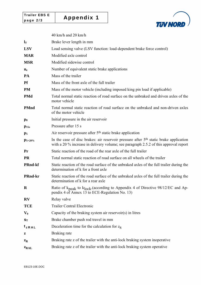
40 km/h and 20 km/h
lT Brake lever length in mm
LSV Load sensing valve (LSV function: load-dependent brake force control)
MAR Modified axle control
MSR Modified sidewise control
ne Number of equivalent static brake applications
PA Mass of the trailer
Pf Mass of the front axle of the full trailer
PM Mass of the motor vehicle (including imposed king pin load if applicable)
PMd Total normal static reaction of road surface on the unbraked and driven axles of the motor vehicle
PMnd Total normal static reaction of road surface on the unbraked and non-driven axles of the motor vehicle
p0 Initial pressure in the air reservoir
p15s Pressure after 15 s
p5 Air reservoir pressure after 5th static brake application
p5+20% In the case of disc brakes: air reservoir pressure after 5th static brake application with a 20 % increase in delivery volume; see paragraph 2.5.2 of this approval report
Pr Static reaction of the road of the rear axle of the full trailer
PR Total normal static reaction of road surface on all wheels of the trailer
PRnd-kf Static reaction of the road surface of the unbraked axles of the full trailer during the determination of k for a front axle
PRnd-kr Static reaction of the road surface of the unbraked axles of the full trailer during the determination of k for a rear axle
R Ratio of kpeak to klock.(according to Appendix 4 of Directive 98/12/EC and Ap-pendix 4 of Annex 13 to ECE-Regulation No. 13)
RV Relay valve
TCE Trailer Central Electronic
V0 Capacity of the braking system air reservoir(s) in litres
sT Brake chamber push rod travel in mm
t z R A L Deceleration time for the calculation for zR
z Braking rate
zR Braking rate z of the trailer with the anti-lock braking system inoperative
zRAL Braking rate z of the trailer with the anti-lock braking system operative
Trailer EBS E
p a g e 3 / 3 Appendix 1
EB123-10E.DOC
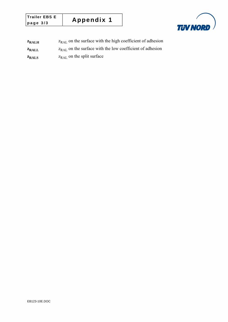
zRALH zRAL on the surface with the high coefficient of adhesion
zRALL zRAL on the surface with the low coefficient of adhesion
zRALS zRAL on the split surface
Trailer EBS E
p a g e 1 / 1 Appendix 2
EB123-10E.DOC
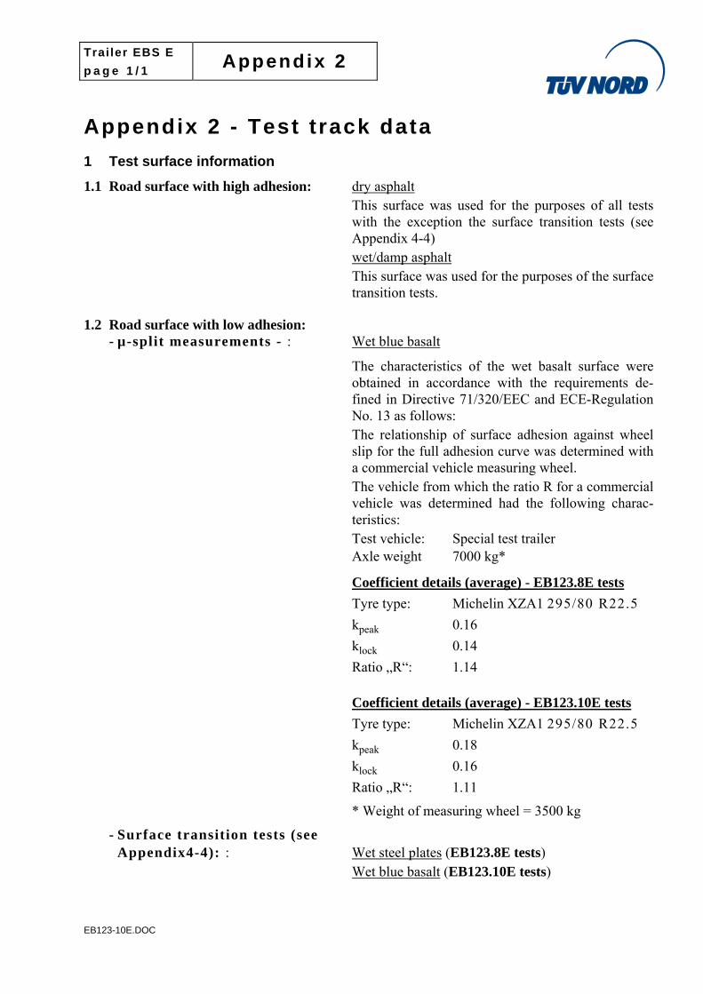
Appendix 2 - Test t rack data
1 Test surface information
1.1 Road surface with high adhesion: dry asphalt This surface was used for the purposes of all tests with the exception the surface transition tests (see Appendix 4-4) wet/damp asphalt This surface was used for the purposes of the surface transition tests.
1.2 Road surface with low adhesion: - µ-split measurements - : Wet blue basalt
The characteristics of the wet basalt surface were obtained in accordance with the requirements de-fined in Directive 71/320/EEC and ECE-Regulation No. 13 as follows: The relationship of surface adhesion against wheel slip for the full adhesion curve was determined with a commercial vehicle measuring wheel. The vehicle from which the ratio R for a commercial vehicle was determined had the following charac-teristics: Test vehicle: Special test trailer Axle weight 7000 kg*
Coefficient details (average) - EB123.8E tests
Tyre type: Michelin XZA1 295/80 R22.5
kpeak 0.16
klock 0.14
Ratio „R“: 1.14
Coefficient details (average) - EB123.10E tests
Tyre type: Michelin XZA1 295/80 R22.5
kpeak 0.18
klock 0.16
Ratio „R“: 1.11
* Weight of measuring wheel = 3500 kg
- Surface transition tests (see Appendix4-4): : Wet steel plates (EB123.8E tests)
Wet blue basalt (EB123.10E tests)
Trailer EBS E
p a g e 1 / 6 Appendix 3
EB123-10E.DOC
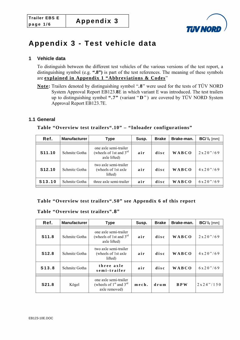
Appendix 3 - Test vehicle data
1 Vehicle data
To distinguish between the different test vehicles of the various versions of the test report, a distinguishing symbol (e.g. “.8”) is part of the test references. The meaning of these symbols are explained in Appendix 1 “Abbreviations & Codes”
Note: Trailers denoted by distinguishing symbol “.8” were used for the tests of TÜV NORD System Approval Report EB123.8E in which variant E was introduced. The test trailers up to distinguishing symbol “.7” (variant “ D ” ) are covered by TÜV NORD System Approval Report EB123.7E.
1.1 General
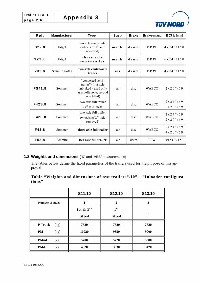
Table “Overview test trailers“.10” – “Inloader configurations”
Ref. Manufacturer Type Susp. Brake Brake-man. BC/ lT [mm]
S11.10 Schmitz Gotha one axle semi-trailer (wheels of 1st and 3rd
axle lifted) a i r d i s c W A B C O 2 x 2 0 ” / 6 9
S12.10 Schmitz Gotha two axle semi-trailer (wheels of 1st axle
lifted) a i r d i s c W A B C O 4 x 2 0 ” / 6 9
S 1 3 . 1 0 Schmitz Gotha three axle semi-trailer a i r d i s c W A B C O 6 x 2 0 ” / 6 9
Table “Overview test trailers“.S0” see Appendix 6 of this report
Table “Overview test trailers“.8”
Ref. Manufacturer Type Susp. Brake Brake-man. BC/ lT [mm]
S11.8 Schmitz Gotha one axle semi-trailer (wheels of 1st and 3rd
axle lifted) a i r d i s c W A B C O 2 x 2 0 ” / 6 9
S12.8 Schmitz Gotha two axle semi-trailer (wheels of 1st axle
lifted) a i r d i s c W A B C O 4 x 2 0 ” / 6 9
S 1 3 . 8 Schmitz Gotha t h r e e a x l e
s e m i - t r a i l e r a i r d i s c W A B C O 6 x 2 0 ” / 6 9
S21.8 Kögel one axle semi-trailer (wheels of 1st and 3rd
axle removed) m e c h . d r u m B P W 2 x 2 4 ” / 1 5 0
Trailer EBS E
p a g e 2 / 6 Appendix 3
EB123-10E.DOC
Ref. Manufacturer Type Susp. Brake Brake-man. BC/ lT [mm]
S22.8 Kögel two axle semi-trailer (wheels of 1st axle
removed) m e c h . d r u m B P W 4 x 2 4 ” / 1 5 0
S 2 3 . 8 Kögel t h r e e a x l e
s e m i - t r a i l e r m e c h . d r u m B P W 6 x 2 4 “ / 1 5 0
Z32.8 Schmitz Gotha two axle centre-axle
trailer a i r d r u m B P W 4 x 2 4 ” / 1 5 0
FS41.8 Sommer
“converted semi-trailer” (first axle
unbraked - used only as a dolly axle, second
axle lifted)
air disc WABCO 2 x 2 0 ” / 6 9
F42S.8 Sommer two axle full trailer
(3nd axle lifted) air disc WABCO
2 x 2 4 ” / 6 9
2 x 2 0 ” / 6 9
F42L.8 Sommer two axle full trailer
(wheels of 2nd axle removed)
air disc WABCO 2 x 2 4 ” / 6 9
2 x 2 0 ” / 6 9
F43.8 Sommer three axle full trailer air disc WABCO 2 x 2 4 ” / 6 9
4 x 2 0 ” / 6 9
F52.8 Schmitz two axle full trailer air drum BPW 4x24’’ /150
1.2 Weights and dimensions (“K” and “ABS” measurements)
The tables below define the fixed parameters of the trailers used for the purpose of this ap-proval.
Table “Weights and dimensions of test trailers“.10” – “Inloader configura-tions”
S11.10 S12.10 S13.10
Number of Axles 1 2 3
1st & 3 r d
l i f ted
1 s t
l i f ted -
P Truck [kg] 7820 7820 7820
PM [kg] 10020 9350 9000
PMnd [kg] 5700 5720 5580
PMd [kg] 4320 3630 3420
Trailer EBS E
p a g e 3 / 6 Appendix 3
EB123-10E.DOC
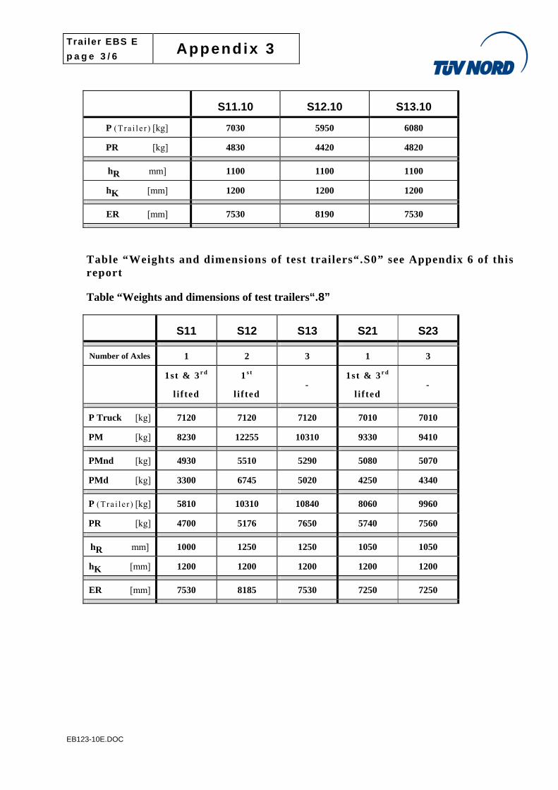
S11.10 S12.10 S13.10
P (Tra i l e r ) [kg] 7030 5950 6080
PR [kg] 4830 4420 4820
hR mm] 1100 1100 1100
hK [mm] 1200 1200 1200
ER [mm] 7530 8190 7530
Table “Weights and dimensions of test trailers“.S0” see Appendix 6 of this report
Table “Weights and dimensions of test trailers“.8”
S11 S12 S13 S21 S23
Number of Axles 1 2 3 1 3
1st & 3 r d
l i f ted
1 s t
l i f ted -
1st & 3 r d
l i f ted -
P Truck [kg] 7120 7120 7120 7010 7010
PM [kg] 8230 12255 10310 9330 9410
PMnd [kg] 4930 5510 5290 5080 5070
PMd [kg] 3300 6745 5020 4250 4340
P (Tra i l e r ) [kg] 5810 10310 10840 8060 9960
PR [kg] 4700 5176 7650 5740 7560
hR mm] 1000 1250 1250 1050 1050
hK [mm] 1200 1200 1200 1200 1200
ER [mm] 7530 8185 7530 7250 7250
Trailer EBS E
p a g e 4 / 6 Appendix 3
EB123-10E.DOC
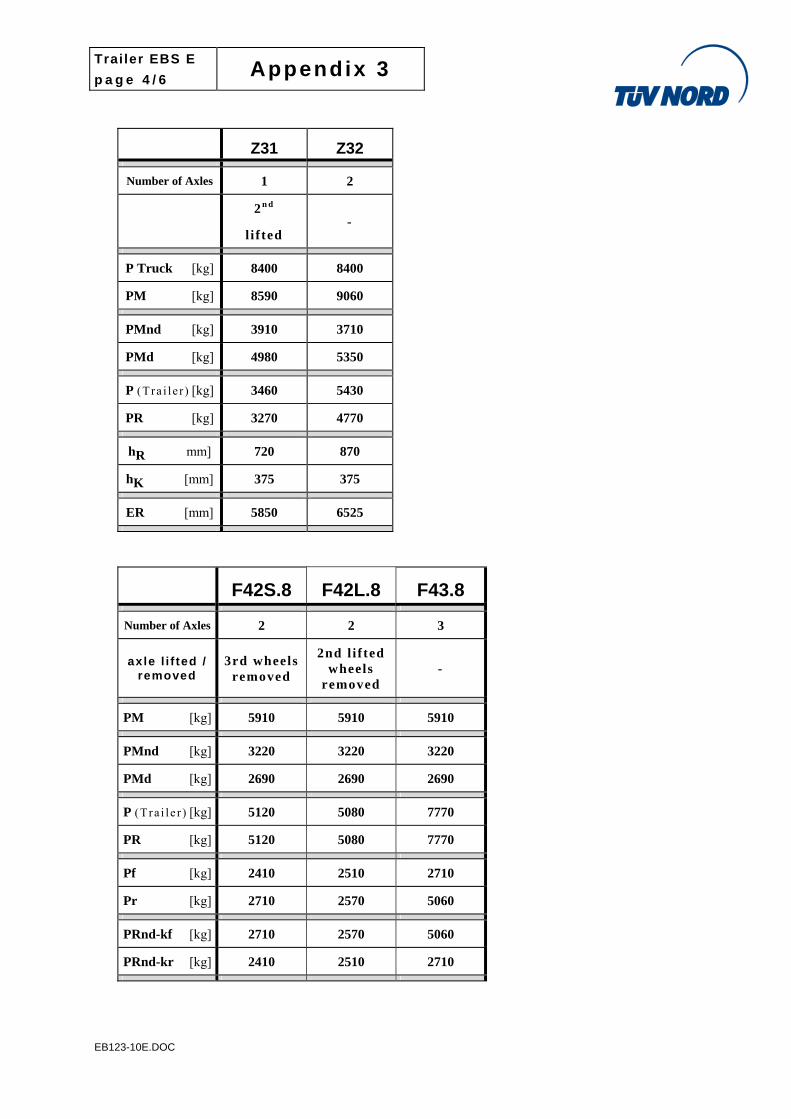
Z31 Z32
Number of Axles 1 2
2 n d
l i f ted -
P Truck [kg] 8400 8400
PM [kg] 8590 9060
PMnd [kg] 3910 3710
PMd [kg] 4980 5350
P (Tra i l e r ) [kg] 3460 5430
PR [kg] 3270 4770
hR mm] 720 870
hK [mm] 375 375
ER [mm] 5850 6525
F42S.8 F42L.8 F43.8
Number of Axles 2 2 3
axle l i f ted / removed
3rd wheels removed
2nd l i f ted wheels
removed -
PM [kg] 5910 5910 5910
PMnd [kg] 3220 3220 3220
PMd [kg] 2690 2690 2690
P (Tra i l e r ) [kg] 5120 5080 7770
PR [kg] 5120 5080 7770
Pf [kg] 2410 2510 2710
Pr [kg] 2710 2570 5060
PRnd-kf [kg] 2710 2570 5060
PRnd-kr [kg] 2410 2510 2710
Trailer EBS E
p a g e 5 / 6 Appendix 3
EB123-10E.DOC
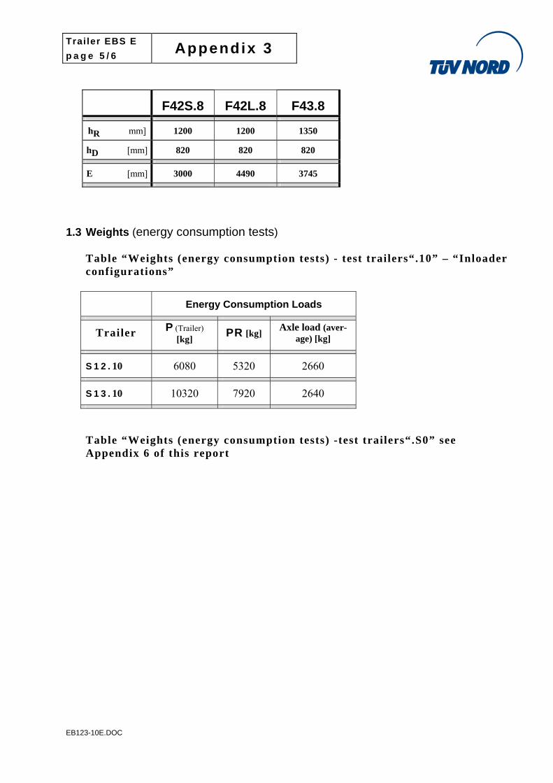
F42S.8 F42L.8 F43.8
hR mm] 1200 1200 1350
hD [mm] 820 820 820
E [mm] 3000 4490 3745
1.3 Weights (energy consumption tests)
Table “Weights (energy consumption tests) - test trailers“.10” – “Inloader configurations”
Energy Consumption Loads
Trailer P (Trailer) [kg] PR [kg] Axle load (aver-
age) [kg]
S 1 2 . 10 6080 5320 2660
S 1 3 . 10 10320 7920 2640
Table “Weights (energy consumption tests) -test trailers“.S0” see Appendix 6 of this report
Trailer EBS E
p a g e 6 / 6 Appendix 3
EB123-10E.DOC
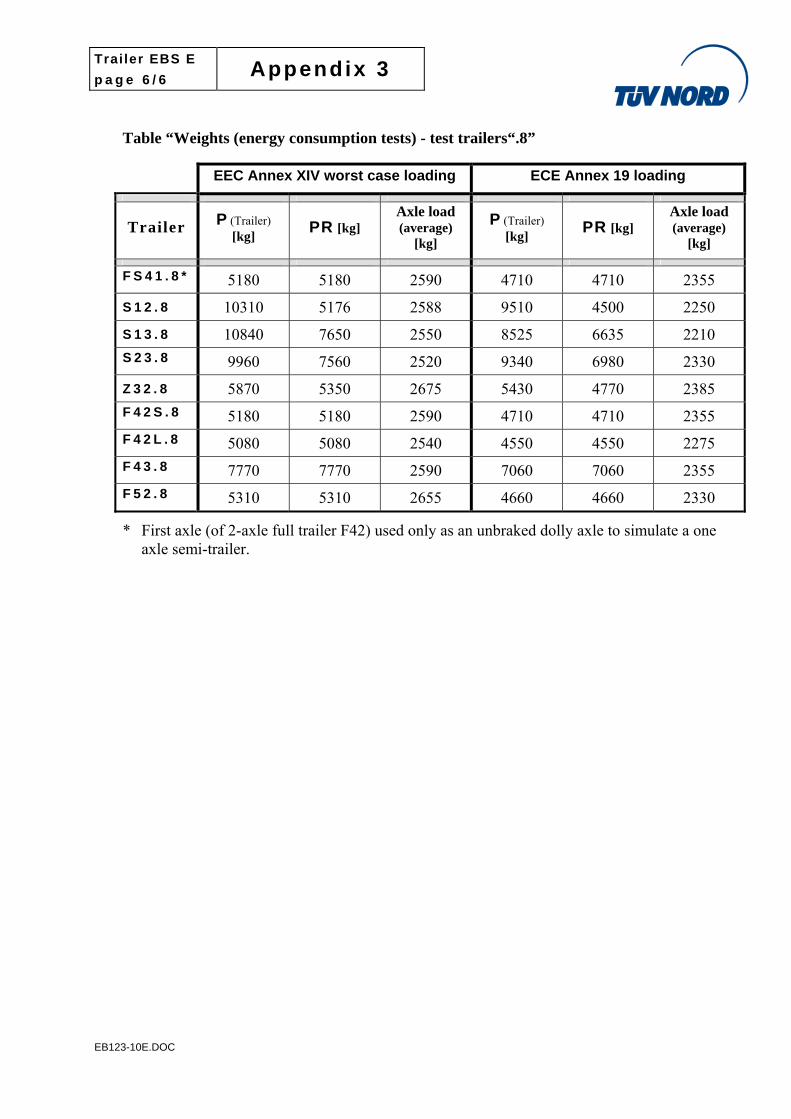
Table “Weights (energy consumption tests) - test trailers“.8”
EEC Annex XIV worst case loading ECE Annex 19 loading
Trailer P (Trailer) [kg] PR [kg]
Axle load (average)
[kg]
P (Trailer) [kg] PR [kg]
Axle load (average)
[kg]
F S 4 1 . 8 * 5180 5180 2590 4710 4710 2355
S 1 2 . 8 10310 5176 2588 9510 4500 2250
S 1 3 . 8 10840 7650 2550 8525 6635 2210
S 2 3 . 8 9960 7560 2520 9340 6980 2330
Z 3 2 . 8 5870 5350 2675 5430 4770 2385
F 4 2 S . 8 5180 5180 2590 4710 4710 2355
F 4 2 L . 8 5080 5080 2540 4550 4550 2275
F 4 3 . 8 7770 7770 2590 7060 7060 2355
F 5 2 . 8 5310 5310 2655 4660 4660 2330
* First axle (of 2-axle full trailer F42) used only as an unbraked dolly axle to simulate a one axle semi-trailer.
Trailer EBS E
p a g e 1 / 4 Appendix 4
EB123-10E.DOC
Appendix 4 - Test results
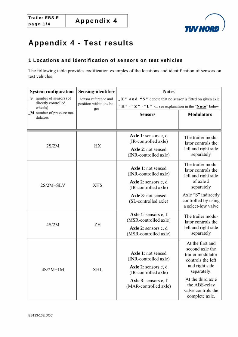
1 Locations and identification of sensors on test vehicles
The following table provides codification examples of the locations and identification of sensors on test vehicles
Notes
„ X “ a n d “ S ” denote that no sensor is fitted on given axle
“ H ” - “ Z ” - “ L ” see explanation in the “Note” below
System configuration _S number of sensors (of
directly controlled wheels)
_M number of pressure mo-dulators
Sensing-identifier
sensor reference and position within the bo-
gie Sensors Modulators
2S/2M HX
Axle 1: sensors c, d (IR-controlled axle)
Axle 2: not sensed (INR-controlled axle)
The trailer modu-lator controls the left and right side
separately
2S/2M+SLV XHS
Axle 1: not sensed (INR-controlled axle)
Axle 2: sensors c, d (IR-controlled axle)
Axle 3: not sensed (SL-controlled axle)
The trailer modu-lator controls the left and right side
of axle 2 separately
Axle “S” indirectly controlled by using a select-low valve
4S/2M ZH
Axle 1: sensors e, f (MSR-controlled axle)
Axle 2: sensors c, d (MSR-controlled axle)
The trailer modu-lator controls the left and right side
separately
4S/2M+1M XHL
Axle 1: not sensed (INR-controlled axle)
Axle 2: sensors c, d (IR-controlled axle)
Axle 3: sensors e, f (MAR-controlled axle)
At the first and second axle the
trailer modulator controls the left and right side
separately.
At the third axle the ABS-relay
valve controls the complete axle.
Trailer EBS E
p a g e 2 / 4 Appendix 4
EB123-10E.DOC
Notes
„ X “ a n d “ S ” denote that no sensor is fitted on given axle
“ H ” - “ Z ” - “ L ” see explanation in the “Note” below
System configuration _S number of sensors (of
directly controlled wheels)
_M number of pressure mo-dulators
Sensing-identifier
sensor reference and position within the bo-
gie Sensors Modulators
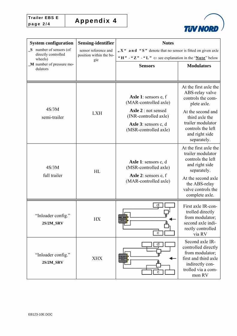
4S/3M
semi-trailer LXH
Axle 1: sensors e, f (MAR-controlled axle)
Axle 2 : not sensed (INR-controlled axle)
Axle 3: sensors c, d (MSR-controlled axle)
At the first axle the ABS-relay valve controls the com-
plete axle.
At the second and third axle the
trailer modulator controls the left and right side
separately.
4S/3M
full trailer HL
Axle 1: sensors c, d (MSR-controlled axle)
Axle 2: sensors e, f (MAR-controlled axle)
At the first axle the trailer modulator controls the left and right side
separately.
At the second axle the ABS-relay
valve controls the complete axle.
“Inloader config.”
2S/2M_SRV HX
First axle IR-con-trolled directly
from modulator; second axle indi-rectly controlled
via RV
“Inloader config.”
2S/2M_SRV XHX
Second axle IR-controlled directly from modulator;
first and third axle indirectly con-
trolled via a com-mon RV
Trailer EBS E
p a g e 3 / 4 Appendix 4
EB123-10E.DOC
Notes
„ X “ a n d “ S ” denote that no sensor is fitted on given axle
“ H ” - “ Z ” - “ L ” see explanation in the “Note” below
System configuration _S number of sensors (of
directly controlled wheels)
_M number of pressure mo-dulators
Sensing-identifier
sensor reference and position within the bo-
gie Sensors Modulators
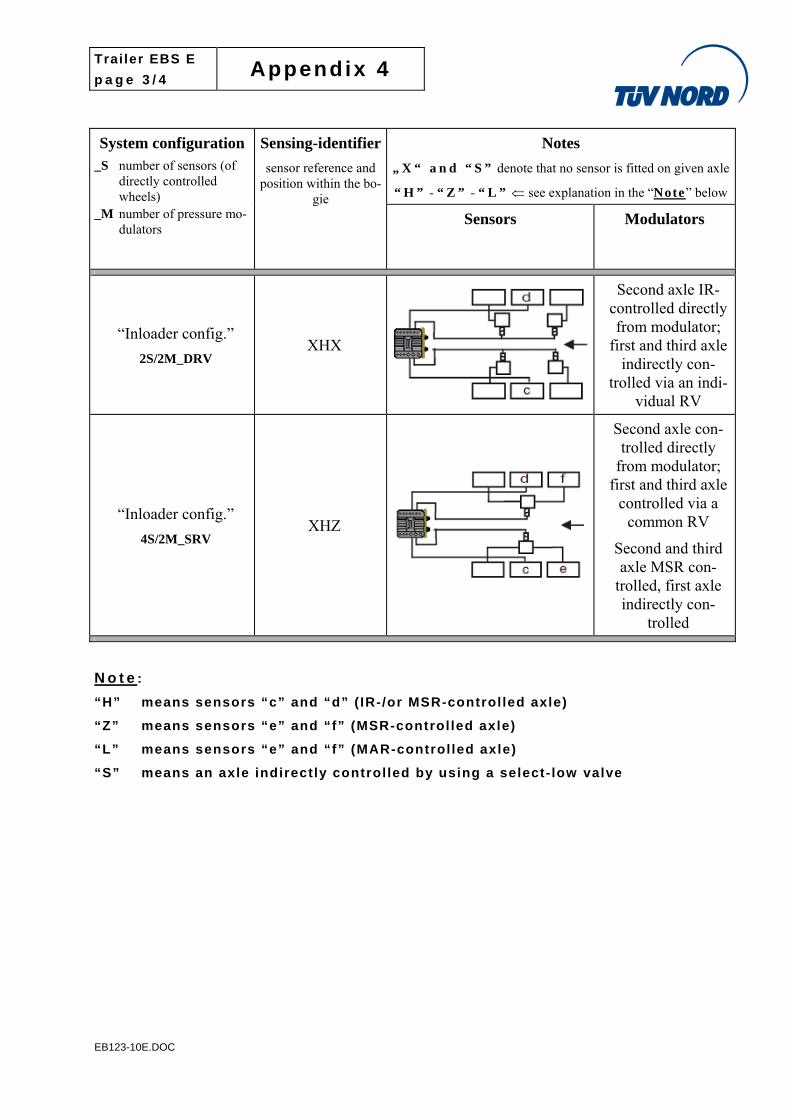
“Inloader config.”
2S/2M_DRV XHX
Second axle IR-controlled directly from modulator;
first and third axle indirectly con-
trolled via an indi-vidual RV
“Inloader config.”
4S/2M_SRV XHZ
Second axle con-trolled directly
from modulator; first and third axle
controlled via a common RV
Second and third axle MSR con-
trolled, first axle indirectly con-
trolled
N o t e :
“H” means sensors “c” and “d” ( IR-/or MSR-control led axle)
“Z” means sensors “e” and “f” (MSR-control led axle)
“L” means sensors “e” and “f” (MAR-control led axle)
“S” means an axle indirectly control led by using a select- low valve
Trailer EBS E
p a g e 4 / 4 Appendix 4
EB123-10E.DOC
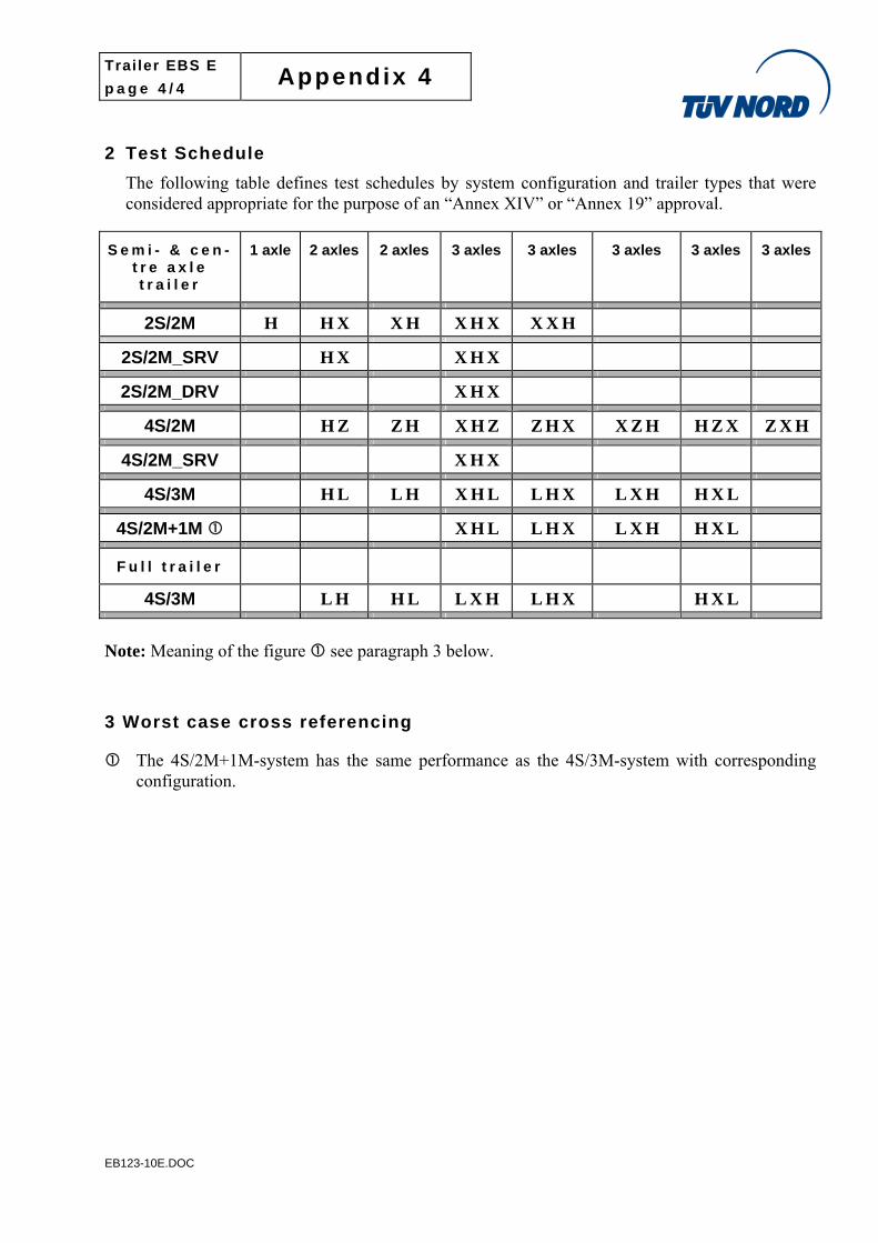
2 Test Schedule
The following table defines test schedules by system configuration and trailer types that were considered appropriate for the purpose of an “Annex XIV” or “Annex 19” approval.
S e m i - & c e n -t r e a x l e t r a i l e r
1 axle 2 axles 2 axles 3 axles 3 axles 3 axles 3 axles 3 axles
2S/2M H H X X H X H X X X H
2S/2M_SRV H X X H X
2S/2M_DRV X H X
4S/2M H Z Z H X H Z Z H X X Z H H Z X Z X H
4S/2M_SRV X H X
4S/3M H L L H X H L L H X L X H H X L
4S/2M+1M X H L L H X L X H H X L
F u l l t r a i l e r
4S/3M L H H L L X H L H X H X L
Note: Meaning of the figure see paragraph 3 below.
3 Worst case cross referencing
The 4S/2M+1M-system has the same performance as the 4S/3M-system with corresponding configuration.
Trailer EBS E
p a g e 1 / 2 Appendix 4 -1
EB123-10E.DOC
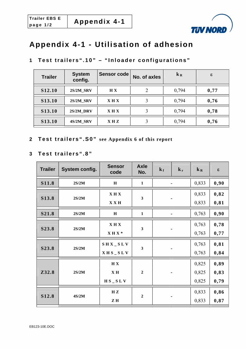
Appendix 4-1 - Ut i l isat ion of adhesion
1 T e s t t r a i l e r s “ . 1 0 ” – “ I n l o a d e r c o n f i g u r a t i o n s ”
Trailer System config.
Sensor codeNo. of axles
k R
S12.10 2S/2M_SRV H X 2 0,794 0,77
S13.10 2S/2M_SRV X H X 3 0,794 0,76
S13.10 2S/2M_DRV X H X 3 0,794 0,78
S13.10 4S/2M_SRV X H Z 3 0,794 0,76
2 T e s t t r a i l e r s “ . S 0 ” see Appendix 6 of this report
3 T e s t t r a i l e r s “ . 8 ”
Trailer System config. Sensor code
Axle No.
k f k r k R
S11.8 2S/2M H 1 - 0,833 0,90
X H X 0,833 0,82 S13.8 2S/2M
X X H 3 -
0,833 0,81
S21.8 2S/2M H 1 - 0,763 0,90
X H X 0,763 0,78 S23.8 2S/2M
X H X * 3 -
0,763 0,77
S H X _ S L V 0,763 0,81 S23.8 2S/2M
X H S _ S L V3 -
0,763 0,84
H X 0,825 0,89
X H 0,825 0,83 Z32.8 2S/2M
H S _ S L V
2 -
0,825 0,79
H Z 0,833 0,86 S12.8 4S/2M
Z H 2 -
0,833 0,87
Trailer EBS E
p a g e 2 / 2 Appendix 4 -1
EB123-10E.DOC
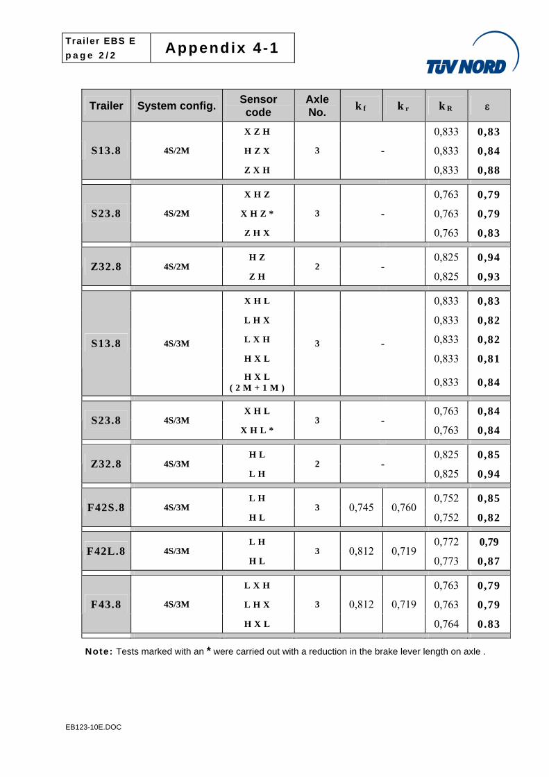
Trailer System config. Sensor code
Axle No.
k f k r k R
X Z H 0,833 0,83
H Z X 0,833 0,84 S13.8 4S/2M
Z X H
3 -
0,833 0,88
X H Z 0,763 0,79
X H Z * 0,763 0,79 S23.8 4S/2M
Z H X
3 -
0,763 0,83
H Z 0,825 0,94 Z32.8 4S/2M
Z H 2 -
0,825 0,93
X H L 0,833 0,83
L H X 0,833 0,82
L X H 0,833 0,82
H X L 0,833 0,81 S13.8 4S/3M
H X L ( 2 M + 1 M )
3 -
0,833 0,84
X H L 0,763 0,84 S23.8 4S/3M
X H L * 3 -
0,763 0,84
H L 0,825 0,85 Z32.8 4S/3M
L H 2 -
0,825 0,94
L H 0,752 0,85 F42S.8 4S/3M
H L 3 0,745 0,760
0,752 0,82
L H 0,772 0,79 F42L.8 4S/3M
H L 3 0,812 0,719
0,773 0,87
L X H 0,763 0,79
L H X 0,763 0,79 F43.8 4S/3M
H X L
3 0,812 0,719
0,764 0.83
Note: Tests marked with an * were carried out with a reduction in the brake lever length on axle .
Trailer EBS E
p a g e 1 / 4 Appendix 4 -2
EB123-10E.DOC
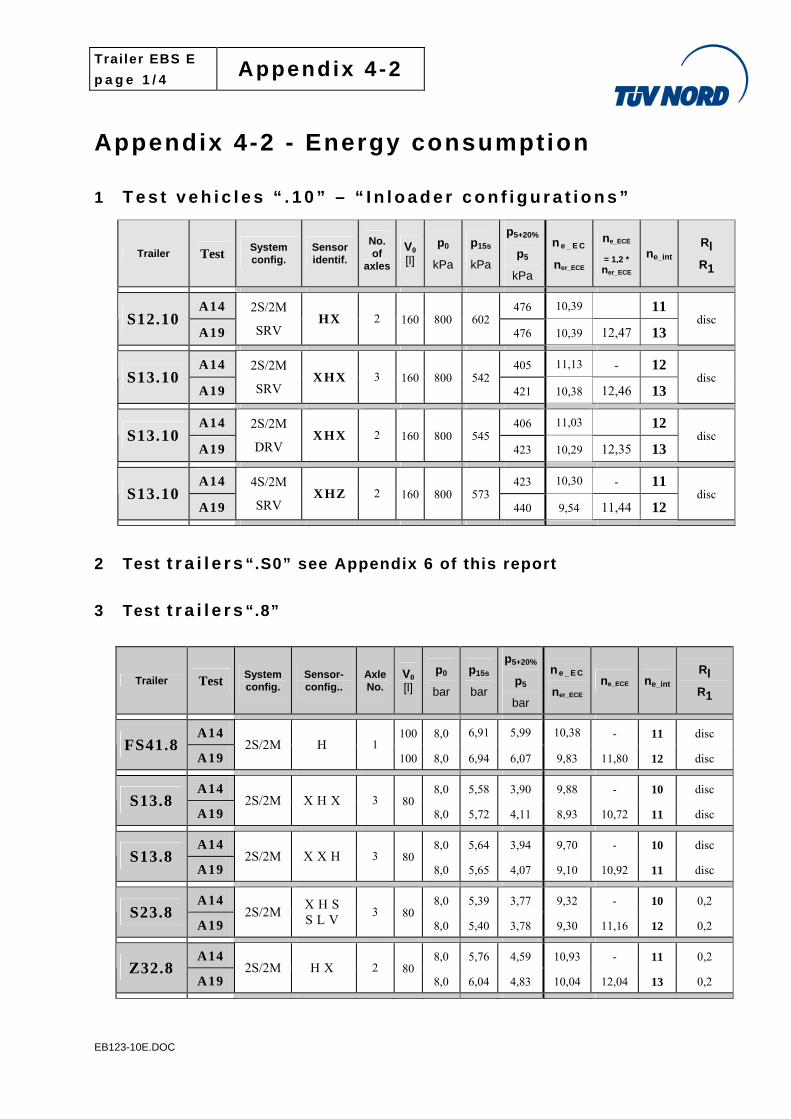
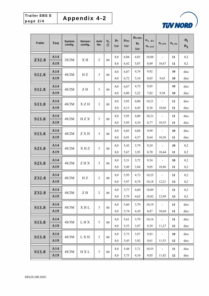
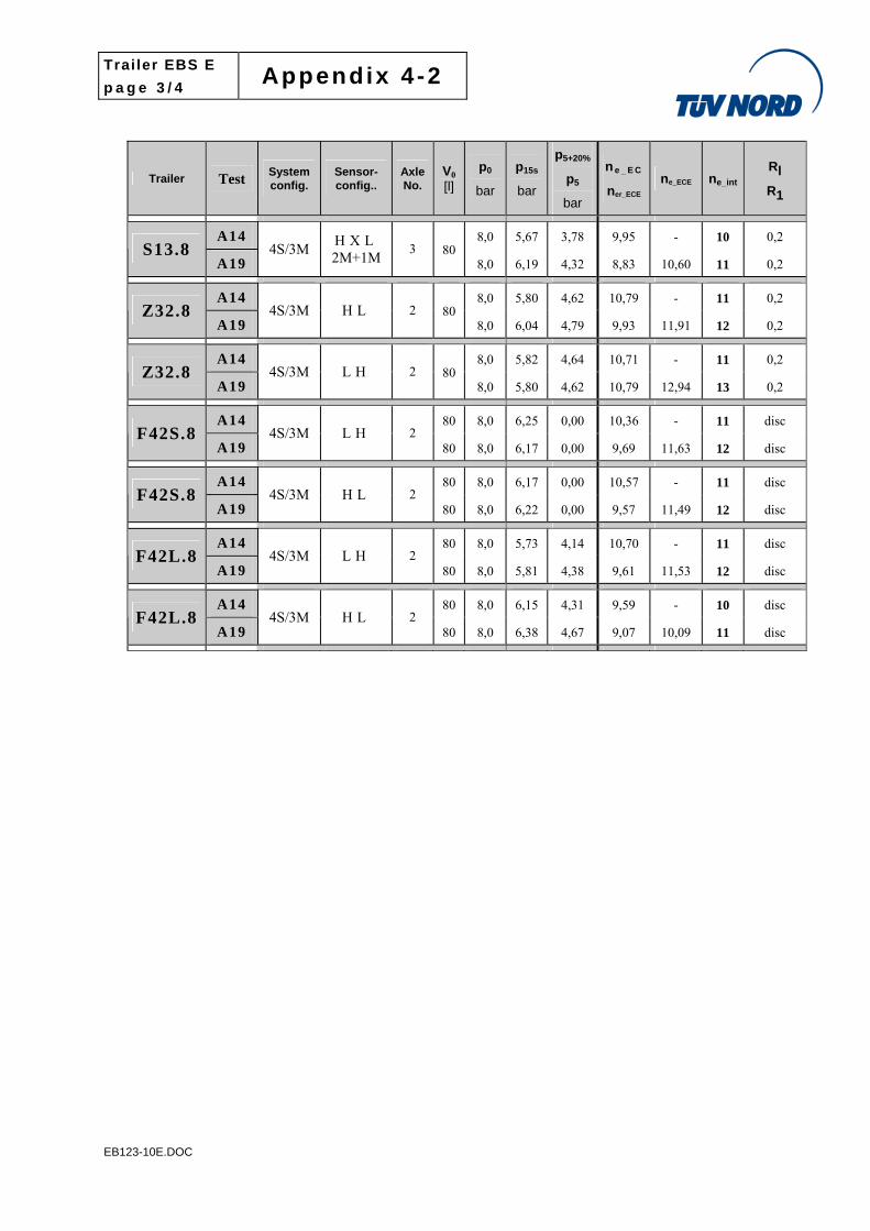
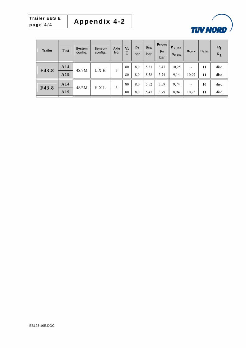
Appendix 4-2 - Energy consumption
1 T e s t v e h i c l e s “ . 1 0 ” – “ I n l o a d e r c o n f i g u r a t i o n s ”
Trailer Test System config.
Sensor identif.
No. of
axles
V0
[l]
p0
kPa
p15s
kPa
p5+20%
p5
kPa
ne _ E C
ner_ECE
ne_ECE
= 1,2 *
ner_ECE
ne_int
Rl
R1
A14 476 10,39 11 S12.10
A19
2S/2M
SRV HX 2 160 800 602
476 10,39 12,47 13 disc
A14 405 11,13 - 12 S13.10
A19
2S/2M
SRV XHX 3 160 800 542
421 10,38 12,46 13 disc
A14 406 11,03 12 S13.10
A19
2S/2M
DRV XHX 2 160 800 545
423 10,29 12,35 13 disc
A14 423 10,30 - 11 S13.10
A19
4S/2M
SRV XHZ 2 160 800 573
440 9,54 11,44 12 disc
2 Test t r a i l e r s “.S0” see Appendix 6 of this report
3 Test t r a i l e r s “.8”
Trailer Test System config.
Sensor-config..
Axle No.
V0
[l]
p0
bar
p15s
bar
p5+20%
p5
bar
ne _ E C
ner_ECE ne_ECE ne_int
Rl
R1
A14 100 8,0 6,91 5,99 10,38 - 11 disc FS41.8
A19 2S/2M H 1
100 8,0 6,94 6,07 9,83 11,80 12 disc
A14 8,0 5,58 3,90 9,88 - 10 disc S13.8
A19 2S/2M X H X 3 80
8,0 5,72 4,11 8,93 10,72 11 disc
A14 8,0 5,64 3,94 9,70 - 10 disc S13.8
A19 2S/2M X X H 3 80
8,0 5,65 4,07 9,10 10,92 11 disc
A14 8,0 5,39 3,77 9,32 - 10 0,2 S23.8
A19 2S/2M
X H S S L V
3 80 8,0 5,40 3,78 9,30 11,16 12 0,2
A14 8,0 5,76 4,59 10,93 - 11 0,2 Z32.8
A19 2S/2M H X 2 80
8,0 6,04 4,83 10,04 12,04 13 0,2
Trailer EBS E
p a g e 2 / 4 Appendix 4 -2
EB123-10E.DOC
Trailer Test System config.
Sensor-config..
Axle No.
V0
[l]
p0
bar
p15s
bar
p5+20%
p5
bar
ne _ E C
ner_ECE ne_ECE ne_int
Rl
R1
A14 8,0 6,04 4,83 10,04 - 11 0,2 Z32.8
A19 2S/2M X H 2 80
8,0 6,42 5,07 8,89 10,67 11 0,2
A14 8,0 6,87 4,74 9,92 10 disc S12.8
A19 4S/2M H Z 3 80
8,0 6,72 5,16 8,03 9,63 10 disc
A14 8,0 6,67 4,75 9,85 10 disc S12.8
A19 4S/2M Z H 3 80
8,0 6,80 5,22 7,82 9,38 10 disc
A14 8,0 5,95 4,00 10,21 - 11 disc S13.8
A19 4S/2M X Z H 3 80
8,0 6,13 4,45 8,36 10,04 11 disc
A14 8,0 5,95 4,00 10,21 - 11 disc S13.8
A19 4S/2M H Z X 3 80
8,0 5,95 4,34 8,77 10,53 11 disc
A14 8,0 6,03 4,04 9,99 - 10 disc S13.8
A19 4S/2M Z X H 3 80
8,0 6,01 4,37 8,64 10,36 11 disc
A14 8,0 5,42 3,79 9,24 - 10 0,2 S23.8
A19 4S/2M X H Z 3 80
8,0 5,67 3,93 8,70 10,44 11 0,2
A14 8,0 5,31 3,72 9,54 - 10 0,2 S23.8
A19 4S/2M Z H X 3 80
8,0 5,49 3,84 9,05 10,86 11 0,2
A14 8,0 5,95 4,73 10,25 - 11 0,2 Z32.8
A19 4S/2M H Z 2 80
8,0 5,97 4,74 10,18 12,21 13 0,2
A14 8,0 5,77 4,60 10,89 - 11 0,2 Z32.8
A19 4S/2M Z H 2 80
8,0 5,79 4,62 10,82 12,99 13 0,2
A14 8,0 5,60 3,79 10,19 - 11 disc S13.8
A19 4S/3M X H L 3 80
8,0 5,74 4,10 8,87 10,64 11 disc
A14 8,0 5,61 3,79 10,16 - 11 disc S13.8
A19 4S/3M L H X 3 80
8,0 5,53 3,97 9,39 11,27 12 disc
A14 8,0 5,73 3,87 9,83 - 10 disc S13.8
A19 4S/3M L X H 3 80
8,0 5,45 3,92 9,61 11,53 12 disc
A14 8,0 5,48 3,71 10,55 - 11 disc S13.8
A19 4S/3M H X L 3 80
8,0 5,75 4,10 9,85 11,82 12 disc
Trailer EBS E
p a g e 3 / 4 Appendix 4 -2
EB123-10E.DOC
Trailer Test System config.
Sensor-config..
Axle No.
V0
[l]
p0
bar
p15s
bar
p5+20%
p5
bar
ne _ E C
ner_ECE ne_ECE ne_int
Rl
R1
A14 8,0 5,67 3,78 9,95 - 10 0,2 S13.8
A19 4S/3M
H X L 2M+1M
3 80 8,0 6,19 4,32 8,83 10,60 11 0,2
A14 8,0 5,80 4,62 10,79 - 11 0,2 Z32.8
A19 4S/3M H L 2 80
8,0 6,04 4,79 9,93 11,91 12 0,2
A14 8,0 5,82 4,64 10,71 - 11 0,2 Z32.8
A19 4S/3M L H 2 80
8,0 5,80 4,62 10,79 12,94 13 0,2
A14 80 8,0 6,25 0,00 10,36 - 11 disc F42S.8
A19 4S/3M L H 2
80 8,0 6,17 0,00 9,69 11,63 12 disc
A14 80 8,0 6,17 0,00 10,57 - 11 disc F42S.8
A19 4S/3M H L 2
80 8,0 6,22 0,00 9,57 11,49 12 disc
A14 80 8,0 5,73 4,14 10,70 - 11 disc F42L.8
A19 4S/3M L H 2
80 8,0 5,81 4,38 9,61 11,53 12 disc
A14 80 8,0 6,15 4,31 9,59 - 10 disc F42L.8
A19 4S/3M H L 2
80 8,0 6,38 4,67 9,07 10,09 11 disc
Trailer EBS E
p a g e 4 / 4 Appendix 4 -2
EB123-10E.DOC
Trailer Test System config.
Sensor-config..
Axle No.
V0
[l]
p0
bar
p15s
bar
p5+20%
p5
bar
ne _ E C
ner_ECE ne_ECE ne_int
Rl
R1
A14 80 8,0 5,31 3,47 10,25 - 11 disc F43.8
A19 4S/3M L X H 3
80 8,0 5,38 3,74 9,14 10,97 11 disc
A14 80 8,0 5,52 3,59 9,74 - 10 disc F43.8
A19 4S/3M H X L 3
80 8,0 5,47 3,79 8,94 10,73 11 disc
Trailer EBS E
p a g e 1 / 3 Appendix 4 -3
EB123-10E.DOC
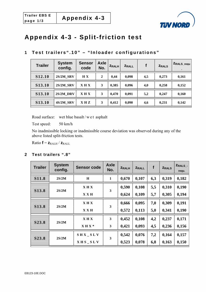
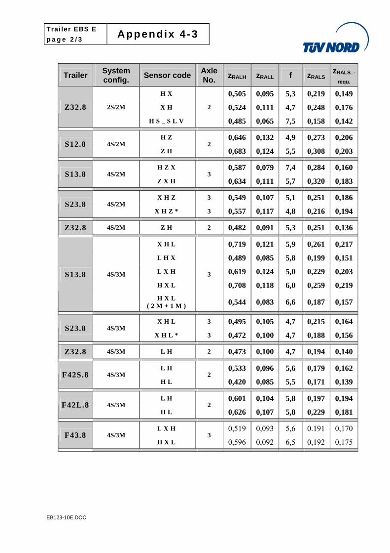
Appendix 4-3 - Spl i t - f r ict ion test
1 T e s t t r a i l e r s “ . 1 0 ” – “ I n l o a d e r c o n f i g u r a t i o n s ”
Trailer System config.
Sensor code
Axle No.
zRALH zRALL f zRALS zRALS_requ
.
S12.10 2S/2M_SRV H X 2 0,44 0,098 4,5 0,273 0,161
S13.10 2S/2M_SRV X H X 3 0,385 0,096 4,0 0,258 0,152
S13.10 2S/2M_DRV X H X 3 0,470 0,091 5,2 0,247 0,160
S13.10 4S/2M_SRV X H Z 3 0,412 0,090 4,6 0,231 0,142
Road surface: wet blue basalt / w e t asphalt
Test speed: 50 km/h
No inadmissible locking or inadmissible course deviation was observed during any of the above listed split-friction tests.
Ratio f = zRALH / zRALL
2 Test trailers “.8”
Trailer System config.
Sensor codeAxle No.
zRALH zRALL f zRALS zRALS_-
requ.
S11.8 2S/2M H 1 0,670 0,107 6,3 0,319 0,182
X H X 0,590 0,108 5,5 0,310 0,190 S13.8 2S/2M
X X H 3
0,624 0,109 5,7 0,305 0,194
X H X 0,666 0,095 7,0 0,309 0,191 S13.8 2S/2M
X X H 3
0,572 0,113 5,0 0,341 0,190
X H X 3 0,452 0,108 4,2 0,237 0,171 S23.8 2S/2M
X H X * 3 0,421 0,093 4,5 0,236 0,156
S H X _ S L V 0,542 0,076 7,2 0,164 0,157 S23.8 2S/2M
X H S _ S L V 3
0,523 0,078 6,8 0,163 0,150
Trailer EBS E
p a g e 2 / 3 Appendix 4 -3
EB123-10E.DOC
Trailer System config.
Sensor codeAxle No.
zRALH zRALL f zRALS zRALS_-
requ.
H X 0,505 0,095 5,3 0,219 0,149
X H 0,524 0,111 4,7 0,248 0,176 Z32.8 2S/2M
H S _ S L V
2
0,485 0,065 7,5 0,158 0,142
H Z 0,646 0,132 4,9 0,273 0,206 S12.8 4S/2M
Z H 2
0,683 0,124 5,5 0,308 0,203
H Z X 0,587 0,079 7,4 0,284 0,160 S13.8 4S/2M
Z X H 3
0,634 0,111 5,7 0,320 0,183
X H Z 3 0,549 0,107 5,1 0,251 0,186 S23.8 4S/2M
X H Z * 3 0,557 0,117 4,8 0,216 0,194
Z32.8 4S/2M Z H 2 0,482 0,091 5,3 0,251 0,136
X H L 0,719 0,121 5,9 0,261 0,217
L H X 0,489 0,085 5,8 0,199 0,151
L X H 0,619 0,124 5,0 0,229 0,203
H X L 0,708 0,118 6,0 0,259 0,219 S13.8 4S/3M
H X L ( 2 M + 1 M )
3
0,544 0,083 6,6 0,187 0,157
X H L 3 0,495 0,105 4,7 0,215 0,164 S23.8 4S/3M
X H L * 3 0,472 0,100 4,7 0,188 0,156
Z32.8 4S/3M L H 2 0,473 0,100 4,7 0,194 0,140
L H 0,533 0,096 5,6 0,179 0,162 F42S.8 4S/3M
H L 2
0,420 0,085 5,5 0,171 0,139
L H 0,601 0,104 5,8 0,197 0,194 F42L.8 4S/3M
H L 2
0,626 0,107 5,8 0,229 0,181
L X H 0,519 0,093 5,6 0.191 0,170 F43.8 4S/3M
H X L 3
0,596 0,092 6,5 0,192 0,175
Trailer EBS E
p a g e 3 / 3 Appendix 4 -3
EB123-10E.DOC
Road surface: wet blue basalt / d ry asphalt
Test speed: 50 km/h
No inadmissible locking or inadmissible course deviation was observed during any of the above listed split-friction tests.
Ratio f = zRALH / zRALL
Trailer EBS E
p a g e 1 / 2 Appendix 4 -4
EB123-10E.DOC
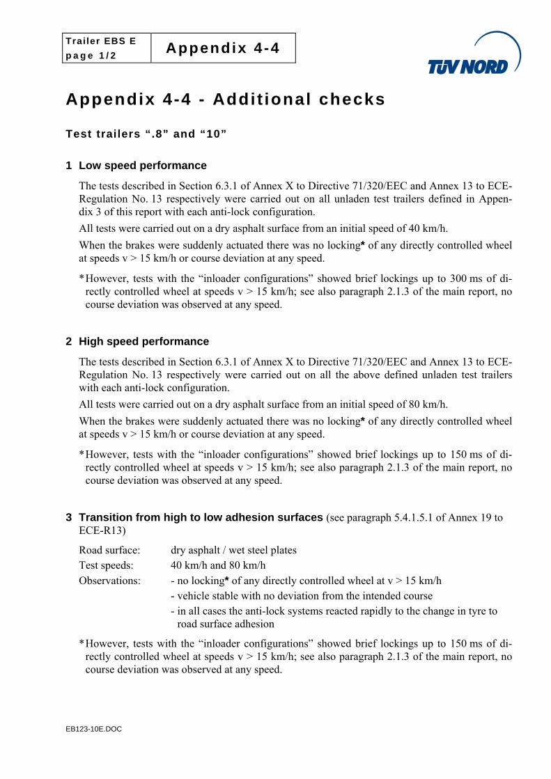
Appendix 4-4 - Addit ional checks Test trailers “.8” and “10”
1 Low speed performance
The tests described in Section 6.3.1 of Annex X to Directive 71/320/EEC and Annex 13 to ECE-Regulation No. 13 respectively were carried out on all unladen test trailers defined in Appen-dix 3 of this report with each anti-lock configuration.
All tests were carried out on a dry asphalt surface from an initial speed of 40 km/h.
When the brakes were suddenly actuated there was no locking* of any directly controlled wheel at speeds v > 15 km/h or course deviation at any speed.
* However, tests with the “inloader configurations” showed brief lockings up to 300 ms of di-rectly controlled wheel at speeds v > 15 km/h; see also paragraph 2.1.3 of the main report, no course deviation was observed at any speed.
2 High speed performance
The tests described in Section 6.3.1 of Annex X to Directive 71/320/EEC and Annex 13 to ECE-Regulation No. 13 respectively were carried out on all the above defined unladen test trailers with each anti-lock configuration.
All tests were carried out on a dry asphalt surface from an initial speed of 80 km/h.
When the brakes were suddenly actuated there was no locking* of any directly controlled wheel at speeds v > 15 km/h or course deviation at any speed.
* However, tests with the “inloader configurations” showed brief lockings up to 150 ms of di-rectly controlled wheel at speeds v > 15 km/h; see also paragraph 2.1.3 of the main report, no course deviation was observed at any speed.
3 Transition from high to low adhesion surfaces (see paragraph 5.4.1.5.1 of Annex 19 to ECE-R13)
Road surface: dry asphalt / wet steel plates Test speeds: 40 km/h and 80 km/h
Observations: - no locking* of any directly controlled wheel at v > 15 km/h - vehicle stable with no deviation from the intended course - in all cases the anti-lock systems reacted rapidly to the change in tyre to
road surface adhesion
* However, tests with the “inloader configurations” showed brief lockings up to 150 ms of di-rectly controlled wheel at speeds v > 15 km/h; see also paragraph 2.1.3 of the main report, no course deviation was observed at any speed.
Trailer EBS E
p a g e 2 / 2 Appendix 4 -4
EB123-10E.DOC
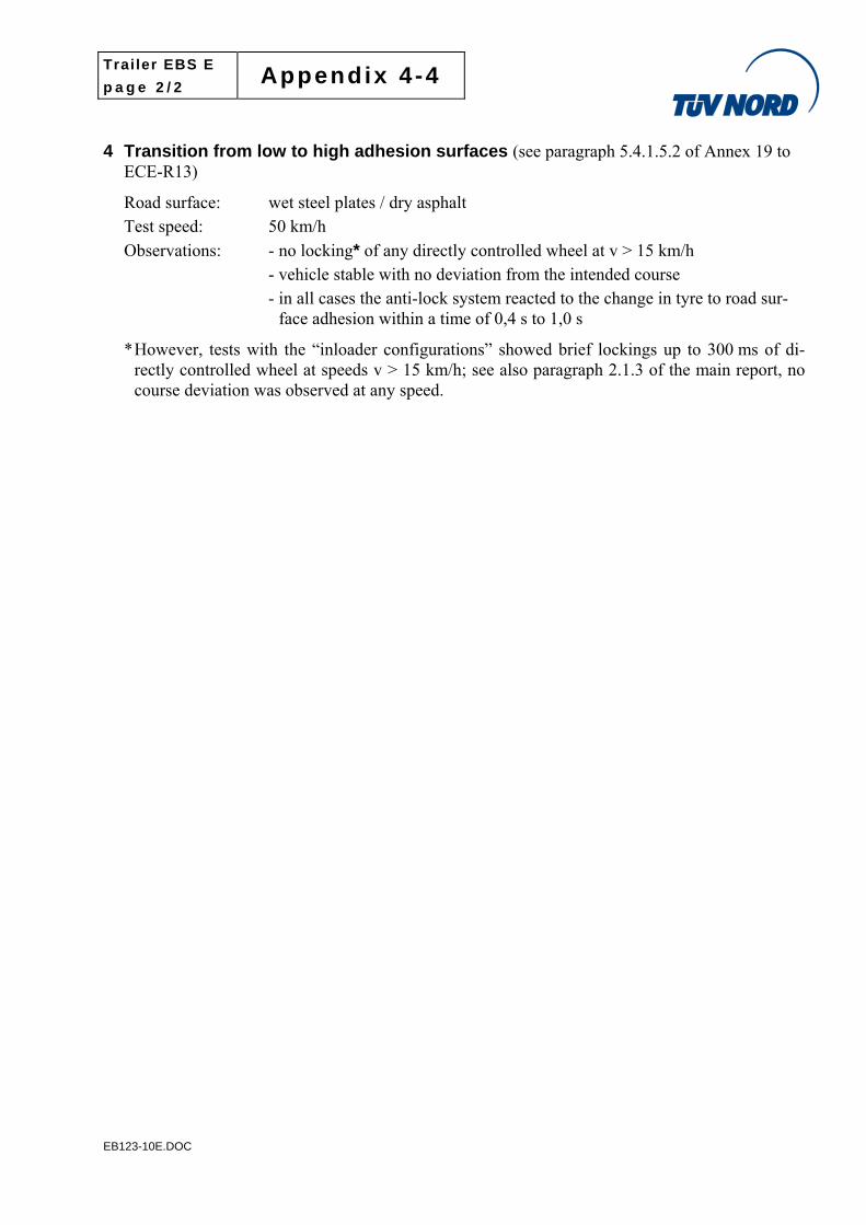
4 Transition from low to high adhesion surfaces (see paragraph 5.4.1.5.2 of Annex 19 to ECE-R13)
Road surface: wet steel plates / dry asphalt Test speed: 50 km/h
Observations: - no locking* of any directly controlled wheel at v > 15 km/h - vehicle stable with no deviation from the intended course - in all cases the anti-lock system reacted to the change in tyre to road sur-
face adhesion within a time of 0,4 s to 1,0 s
* However, tests with the “inloader configurations” showed brief lockings up to 300 ms of di-rectly controlled wheel at speeds v > 15 km/h; see also paragraph 2.1.3 of the main report, no course deviation was observed at any speed.
Trailer EBS E
p a g e 1 / 5 Appendix 5
EB123-10E.DOC
Appendix 5 - Further test results
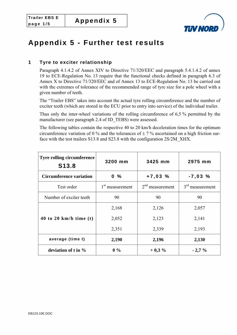
1 Tyre to exciter relationship
Paragraph 4.1.4.2 of Annex XIV to Directive 71/320/EEC and paragraph 5.4.1.4.2 of annex 19 to ECE-Regulation No. 13 require that the functional checks defined in paragraph 6.3 of Annex X to Directive 71/320/EEC and of Annex 13 to ECE-Regulation No. 13 be carried out with the extremes of tolerance of the recommended range of tyre size for a pole wheel with a given number of teeth.
The “Trailer EBS” takes into account the actual tyre rolling circumference and the number of exciter teeth (which are stored in the ECU prior to entry into service) of the individual trailer.
Thus only the inter-wheel variations of the rolling circumference of 6,5 % permitted by the manufacturer (see paragraph 2.4 of ID_TEBS) were assessed.
The following tables contain the respective 40 to 20 km/h deceleration times for the optimum circumference variation of 0 % and the tolerances of 7 % ascertained on a high friction sur-face with the test trailers S13.8 and S23.8 with the configuration 2S/2M_XHX.
Tyre rolling circumference
S13.8 3200 mm 3425 mm 2975 mm
Circumference variation 0 % + 7 , 0 3 % - 7 , 0 3 %
Test order 1st measurement 2nd measurement 3rd measurement
Number of exciter teeth 90 90 90
2,168 2,126 2,057
2,052 2,123 2,141
40 to 20 km/h time (t)
2,351 2,339 2,193
average (t ime t) 2,190 2,196 2,130
deviation of t in % 0 % + 0,3 % - 2,7 %
Trailer EBS E
p a g e 2 / 5 Appendix 5
EB123-10E.DOC
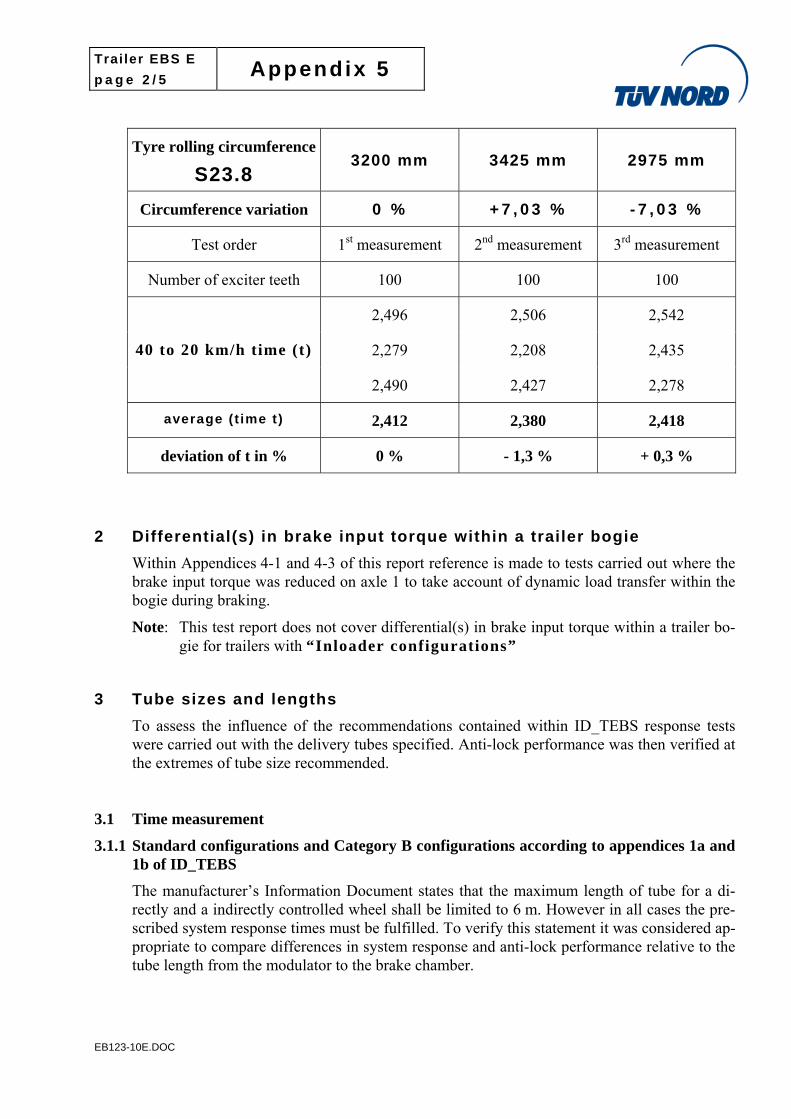
Tyre rolling circumference
S23.8 3200 mm 3425 mm 2975 mm
Circumference variation 0 % + 7 , 0 3 % - 7 , 0 3 %
Test order 1st measurement 2nd measurement 3rd measurement
Number of exciter teeth 100 100 100
2,496 2,506 2,542
2,279 2,208 2,435
40 to 20 km/h time (t)
2,490 2,427 2,278
average (t ime t) 2,412 2,380 2,418
deviation of t in % 0 % - 1,3 % + 0,3 %
2 Differential(s) in brake input torque within a trailer bogie
Within Appendices 4-1 and 4-3 of this report reference is made to tests carried out where the brake input torque was reduced on axle 1 to take account of dynamic load transfer within the bogie during braking.
Note: This test report does not cover differential(s) in brake input torque within a trailer bo-gie for trailers with “Inloader configurations”
3 Tube sizes and lengths
To assess the influence of the recommendations contained within ID_TEBS response tests were carried out with the delivery tubes specified. Anti-lock performance was then verified at the extremes of tube size recommended.
3.1 Time measurement
3.1.1 Standard configurations and Category B configurations according to appendices 1a and 1b of ID_TEBS
The manufacturer’s Information Document states that the maximum length of tube for a di-rectly and a indirectly controlled wheel shall be limited to 6 m. However in all cases the pre-scribed system response times must be fulfilled. To verify this statement it was considered ap-propriate to compare differences in system response and anti-lock performance relative to the tube length from the modulator to the brake chamber.
Trailer EBS E
p a g e 3 / 5 Appendix 5
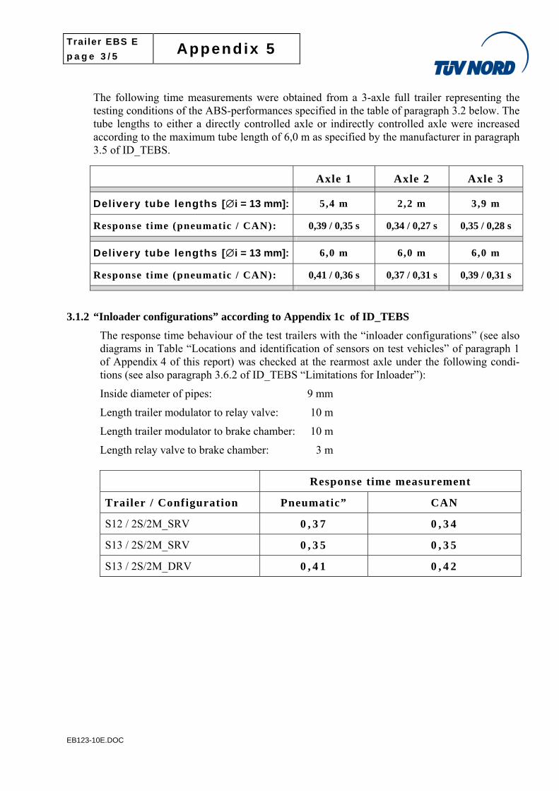
EB123-10E.DOC
The following time measurements were obtained from a 3-axle full trailer representing the testing conditions of the ABS-performances specified in the table of paragraph 3.2 below. The tube lengths to either a directly controlled axle or indirectly controlled axle were increased according to the maximum tube length of 6,0 m as specified by the manufacturer in paragraph 3.5 of ID_TEBS.
Axle 1 Axle 2 Axle 3
Delivery tube lengths [i = 13 mm]: 5,4 m 2,2 m 3,9 m
Response t ime (pneumatic / CAN): 0,39 / 0,35 s 0,34 / 0,27 s 0,35 / 0,28 s
Delivery tube lengths [i = 13 mm]: 6,0 m 6,0 m 6,0 m
Response t ime (pneumatic / CAN): 0,41 / 0,36 s 0,37 / 0,31 s 0,39 / 0,31 s
3.1.2 “Inloader configurations” according to Appendix 1c of ID_TEBS
The response time behaviour of the test trailers with the “inloader configurations” (see also diagrams in Table “Locations and identification of sensors on test vehicles” of paragraph 1 of Appendix 4 of this report) was checked at the rearmost axle under the following condi-tions (see also paragraph 3.6.2 of ID_TEBS “Limitations for Inloader”):
Inside diameter of pipes: 9 mm
Length trailer modulator to relay valve: 10 m
Length trailer modulator to brake chamber: 10 m
Length relay valve to brake chamber: 3 m
Response time measurement
Trailer / Configuration Pneumatic” CAN
S12 / 2S/2M_SRV 0 , 3 7 0 , 3 4
S13 / 2S/2M_SRV 0 , 3 5 0 , 3 5
S13 / 2S/2M_DRV 0 , 4 1 0 , 4 2
Trailer EBS E
p a g e 4 / 5 Appendix 5
EB123-10E.DOC
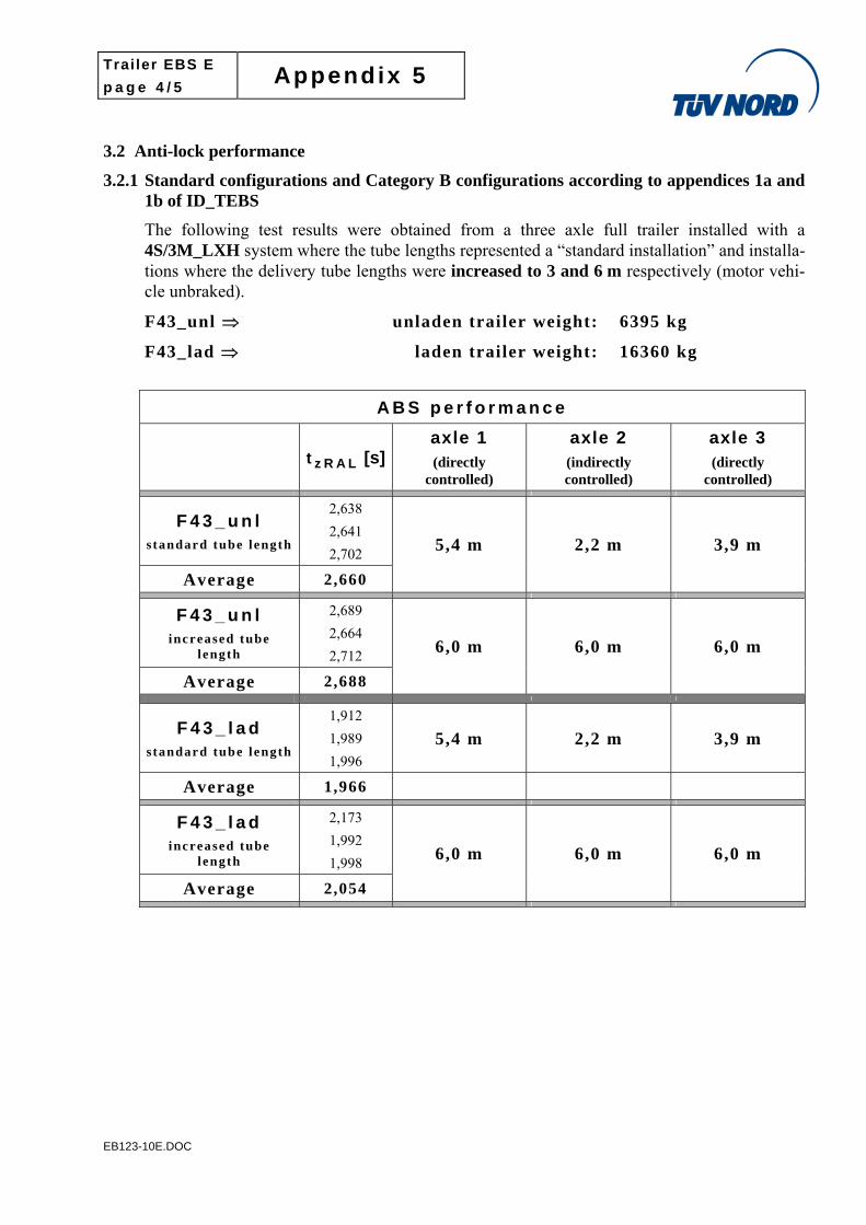
3.2 Anti-lock performance
3.2.1 Standard configurations and Category B configurations according to appendices 1a and 1b of ID_TEBS
The following test results were obtained from a three axle full trailer installed with a 4S/3M_LXH system where the tube lengths represented a “standard installation” and installa-tions where the delivery tube lengths were increased to 3 and 6 m respectively (motor vehi-cle unbraked).
F43_unl unladen trailer weight: 6395 kg
F43_lad laden trailer weight: 16360 kg
A B S p e r f o r m a n c e
t z R A L [s]axle 1 (directly
controlled)
axle 2 (indirectly controlled)
axle 3 (directly
controlled)
F 4 3 _ u n l s tandard tube length
2,638
2,641
2,702
Average 2,660
5,4 m 2,2 m 3,9 m
F 4 3 _ u n l increased tube
length
2,689
2,664
2,712
Average 2,688
6,0 m 6,0 m 6,0 m
F 4 3 _ l a d s tandard tube length
1,912
1,989
1,996
5,4 m 2,2 m 3,9 m
Average 1,966
F 4 3 _ l a d increased tube
length
2,173
1,992
1,998
Average 2,054
6,0 m 6,0 m 6,0 m
Trailer EBS E
p a g e 5 / 5 Appendix 5
EB123-10E.DOC
All comparison tests were carried out on a dry asphalt surface.
The above tests with the various tube length variations show that the utilisation of adhesion times t z R A L are within the following tolerances:
a) Comparison between the standard and increased tube length condition in relation to the respective mean values for the unladen and laden state:
For the unladen state the deviation was 0 . 5 2 % and for the laden state the deviation was 2 . 1 9 % .
b) Variation of the test results in relation to the respective mean values for the unladen and laden state:
For the unladen state the measured utilisation of adhesion times lay in a tolerance band of 2.8 % whereas for the laden state the tolerance band was 1 3 % .
3.2.2 “Inloader configurations” according to Appendix 1c of ID_TEBS
see paragraph 1 of Appendix 4-1 “Utilisation of adhesion”
Trailer EBS E
p a g e 1 / 3 Appendix 6
EB123-10E.DOC
Appendix 6 – Supplementary Tests ECE-Annex 20, paragraph 7.4
1 General
The purpose of the tests carried out with the test trailers S21.S0 and C12.S0 (see paragraph 3 below) is to demonstrate the performance of a one- or two-axle trailer with select low control (ABS category B). These trailers do not fulfil the split-µ requirements of paragraph 6.3.2 of Annex 13 due to its select low control (SL) and therefore they do not fulfil the Category ‘A’ requirements (see also paragraph 2.1.2 in the main report). However, when these SL-controlled axles are combined with other IR-controlled axles to a multi-axle trailer all relevant ABS requirements may be ful-filled for the installations/configurations of these multi-axle trailers. The fulfilment of compliance with all of the relevant ABS requirements has to be confirmed by a special test report according to paragraph 7.4, of ECE-R13-Annex 20. Thus, these supplementary tests of this Appendix 6 are added to this report for the utilizing the procedure as laid down in ECE-R13, Annex 20, paragraph 7.4. However, as the tests described below only confirm compliance with the ABS Category ‘B’ re-quirements, a Test Report according to the procedure of ECE-R13-Annex 20, paragraph 7.4 shall demonstrate that also fulfilment of compliance with the split-µ requirements of paragraph 6.3.2 and Appendix 3, paragraph 2 respectively of Annex 13 are fulfilled.
It should be noted that Appendix 6 is added to this report only for the purpose of apply-ing the procedure according to ECE-R13, Annex 20, paragraph 7.4 but not as testing re-sults according to ECE Regulation No. 13 - Annex 19 or Directive 71/320/EEC - Annex XIV.
2 Test surface information: n / a (only high adhesion surface)
3 Test trailers
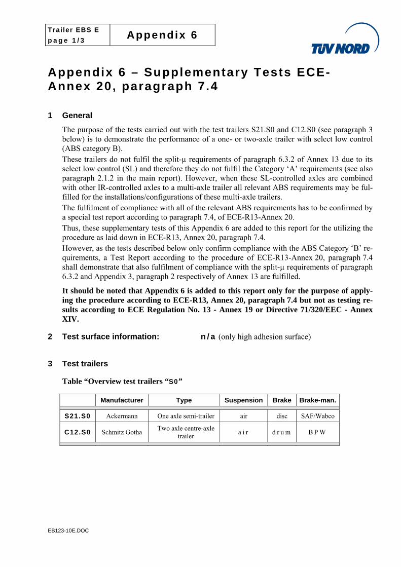
Table “Overview test trailers “S0”
Manufacturer Type Suspension Brake Brake-man.
S21.S0 Ackermann One axle semi-trailer air disc SAF/Wabco
C12.S0 Schmitz Gotha Two axle centre-axle
trailer a i r d r u m B P W
Trailer EBS E
p a g e 2 / 3 Appendix 6
EB123-10E.DOC
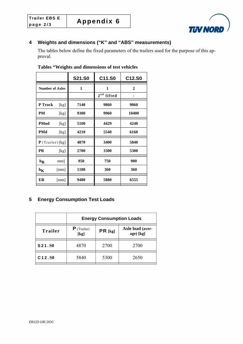
4 Weights and dimensions (“K” and “ABS” measurements)
The tables below define the fixed parameters of the trailers used for the purpose of this ap-proval.
Tables “Weights and dimensions of test vehicles
S21.S0 C11.S0 C12.S0
Number of Axles 1 1 2
2 n d l i f ted -
P Truck [kg] 7140 9860 9860
PM [kg] 9300 9960 10400
PMnd [kg] 5100 4429 4240
PMd [kg] 4210 5540 6160
P (Tra i l e r ) [kg] 4870 3400 5840
PR [kg] 2700 3300 5300
hR mm] 950 750 900
hK [mm] 1180 360 360
ER [mm] 9480 5880 6555
5 Energy Consumption Test Loads
Energy Consumption Loads
Trailer P (Trailer) [kg] PR [kg] Axle load (aver-
age) [kg]
S 2 1 . S0 4870 2700 2700
C 1 2 . S0 5840 5300 2650
Trailer EBS E
p a g e 3 / 3 Appendix 6
EB123-10E.DOC
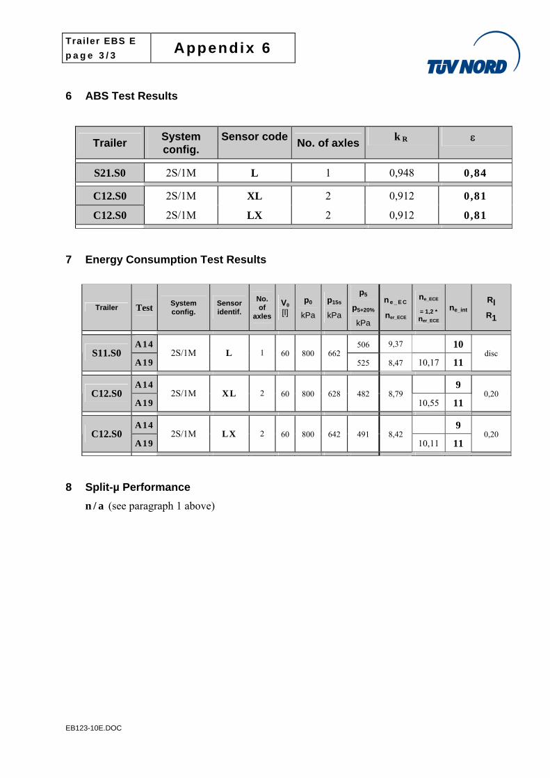
6 ABS Test Results
Trailer System config.
Sensor codeNo. of axles
k R
S21.S0 2S/1M L 1 0,948 0,84
C12.S0 2S/1M XL 2 0,912 0,81
C12.S0 2S/1M LX 2 0,912 0,81
7 Energy Consumption Test Results
Trailer Test System config.
Sensor identif.
No. of
axles
V0
[l]
p0
kPa
p15s
kPa
p5
p5+20%
kPa
ne _ E C
ner_ECE
ne_ECE
= 1,2 *
ner_ECE
ne_int
Rl
R1
A14 506 9,37 10 S11.S0
A19 2S/1M L 1 60 800 662
525 8,47 10,17 11 disc
A14 9 C12.S0
A19 2S/1M XL 2 60 800 628 482 8,79
10,55 11 0,20
A14 9 C12.S0
A19 2S/1M LX 2 60 800 642 491 8,42
10,11 11 0,20
8 Split-µ Performance
n / a (see paragraph 1 above)
INFORMATION DOCUMENT
Directive 71/ 320 – Annex XIV ECE Regulation 13/10
Trailer Anti-Lock Braking System
Information Document ID_EB123_10
Electronically controlled Brake System (EBS) for trailers
Trailer EBS E Trailer EBS E with TCE
Stender A 24.01.2007 COPYRIGHT
Stender B 07.03.2008 APPR. LEV. DATE NAME
Stender C 25.01.2010 COMPILER 15.01.2007 A. Stender
Stender D 25.08.2011 2 15.01.2007 N. Witte
3 Trailer EBS E
4
TRI PRODUCT IDENTIFICATION NO. DOC.NAME SHEET
Name REVISION DATE 400 200 220 0 ID_123_10E.DOC 1/58
WABCO Vehicle Control Systems 2/58
Trailer EBS Information Document
Information document for Trailer EBS This information document is produced in accordance to Annex XIV of Directive 71/320/EEC and Annex 19 of ECE R13. The information contained in this document is used for the type approval of the prescribed braking system.
1 General 1.1 Name of manufacturer
WABCO Fahrzeugsysteme GmbH Am Lindener Hafen 21 D-30453 Hannover
1.2 System name/model: Trailer EBS
1.3 System variant: E
Versions:
Trailer EBS E
Trailer EBS E with TCE* * TCE: Trai ler Central Electronic
Note: Regarding the description of the above mentioned different versions see paragraph 3.2
1.4 System configurations
2S/2M, 2 sensors and one trailer modulator for 1- to 3-axle semi- and centre-axle trailer with air suspension or mechanical suspension.
2S/2M+SLV, 2 sensors, one trailer modulator and one select low valve for 2- to 3-axle semi- and centre-axle trailer with air suspension or mechanical suspension and one self-steering axle.
4S/2M, 4 sensors and one trailer modulator for 2- and 3-axle semi-and centre-axle trailer with air suspension or mechanical suspension.
4S/2M + 1M, 4 sensors, one trailer modulator and one ABS-relay valve for 3- to 4-axle semi-trailers and 3-axle centre-axle trailers with air suspension or mechanical suspension.
4S/3M, 4 sensors, one trailer modulator and one EBS-relay valve for 2- to 3-axle full trailers and 2- to 3-axle semi-trailer and 2- and 3-axle centre-axle trailer with air suspension or mechanical suspension.
WABCO Vehicle Control Systems 3/58
Trailer EBS Information Document
1.5 Explanation of the basic functions and philosophy of the system
Electronically controlled braking system with load-dependent brake pressure regulation and automatic anti-lock device.
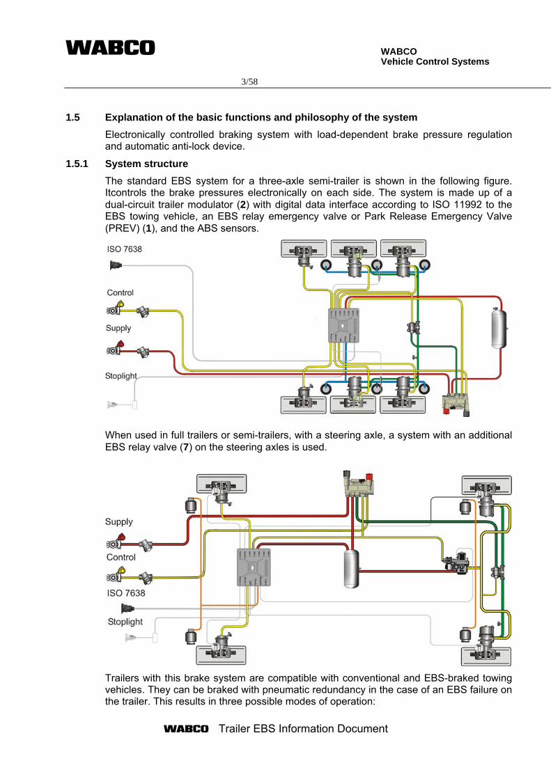
1.5.1 System structure
The standard EBS system for a three-axle semi-trailer is shown in the following figure. Itcontrols the brake pressures electronically on each side. The system is made up of a dual-circuit trailer modulator (2) with digital data interface according to ISO 11992 to the EBS towing vehicle, an EBS relay emergency valve or Park Release Emergency Valve (PREV) (1), and the ABS sensors.
When used in full trailers or semi-trailers, with a steering axle, a system with an additional EBS relay valve (7) on the steering axles is used.
Trailers with this brake system are compatible with conventional and EBS-braked towing vehicles. They can be braked with pneumatic redundancy in the case of an EBS failure on the trailer. This results in three possible modes of operation:
WABCO Vehicle Control Systems 4/58
Trailer EBS Information Document
a) Operation behind towing vehicles with EBS and extended (7 pin) ISO 7638 plug-type connection with CAN interface according to ISO 11992.
All EBS functions can be utilised. The driver's braking demand (set value) is transmitted via the data interface to the trailer vehicle.
b) Operation behind conventional towing vehicles with ISO 7638 plug-type connection, without CAN interface
All EBS functions can be used except for transmission of the demand value via the CAN interface. The demand value is specified by the pressure sensor in the relay emergency valve. This pressure sensor measures the trailer control line pressure.
c) Redundancy operation
1. without ISO 1185 or ISO 12098-powering
If the electrical power supply fails or is not plugged in the braking is controlled pneumatically, although without load-dependent brake force control and without ABS function.
2. with ISO 1185 or ISO 12098-powering as a safety function
It is not allowed to use the trailer without the ISO 7638 connector. If the electrical power supply via ISO 7638 fails and the system is fitted by an ISO 1185 or ISO 12098-cable (optional feature), the system can be supplied by this optional connection (stoplight-powering). In this case only ABS and the load-dependent brake force control are in function with reduced performance.
WABCO Vehicle Control Systems 5/58
Trailer EBS Information Document
lat. decelleration sensor
Drucksensor ISO 7638 / CAN
Driver-Demand sel.
LSV-Funktion
RSS
PU
ABS
Press. control
PU
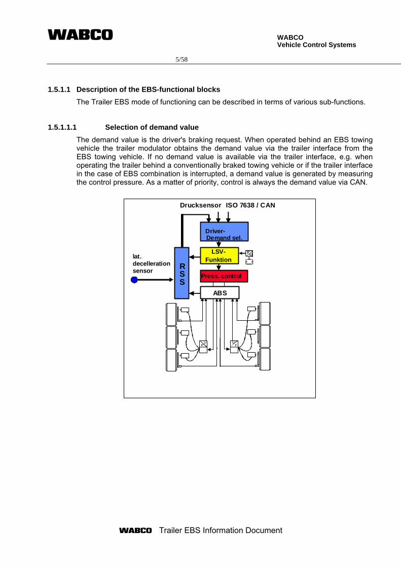
1.5.1.1 Description of the EBS-functional blocks
The Trailer EBS mode of functioning can be described in terms of various sub-functions.
1.5.1.1.1 Selection of demand value
The demand value is the driver's braking request. When operated behind an EBS towing vehicle the trailer modulator obtains the demand value via the trailer interface from the EBS towing vehicle. If no demand value is available via the trailer interface, e.g. when operating the trailer behind a conventionally braked towing vehicle or if the trailer interface in the case of EBS combination is interrupted, a demand value is generated by measuring the control pressure. As a matter of priority, control is always the demand value via CAN.
WABCO Vehicle Control Systems 6/58
Trailer EBS Information Document
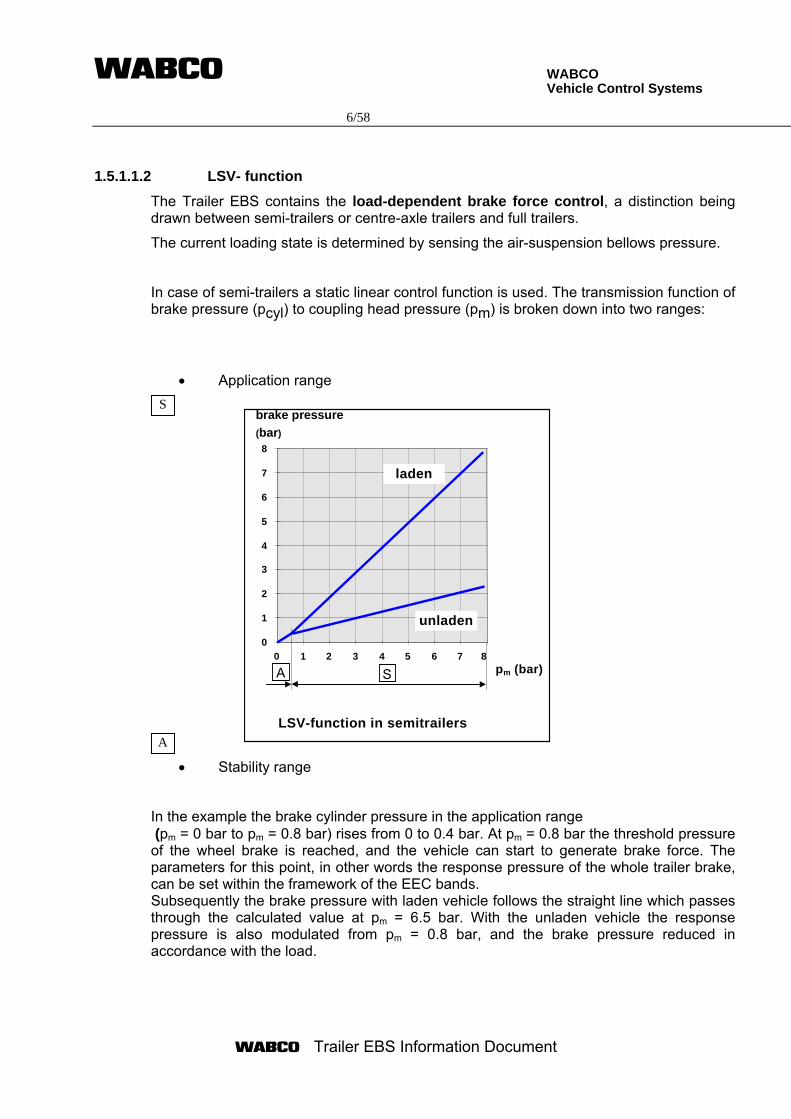
1.5.1.1.2 LSV- function
The Trailer EBS contains the load-dependent brake force control, a distinction being drawn between semi-trailers or centre-axle trailers and full trailers.
The current loading state is determined by sensing the air-suspension bellows pressure.
In case of semi-trailers a static linear control function is used. The transmission function of brake pressure (pcyl) to coupling head pressure (pm) is broken down into two ranges:
• Application range
• Stability range
In the example the brake cylinder pressure in the application range (pm = 0 bar to pm = 0.8 bar) rises from 0 to 0.4 bar. At pm = 0.8 bar the threshold pressure of the wheel brake is reached, and the vehicle can start to generate brake force. The parameters for this point, in other words the response pressure of the whole trailer brake, can be set within the framework of the EEC bands. Subsequently the brake pressure with laden vehicle follows the straight line which passes through the calculated value at pm = 6.5 bar. With the unladen vehicle the response pressure is also modulated from pm = 0.8 bar, and the brake pressure reduced in accordance with the load.
A
S
0
1
2
3
4
5
6
7
8
0 1 2 3 4 5 6 7 8pm (bar)
brake pressure
(bar)
laden
unladen
LSV-function in semitrailers
A S
WABCO Vehicle Control Systems 7/58
Trailer EBS Information Document
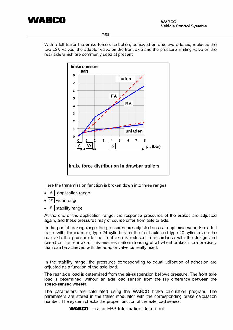
With a full trailer the brake force distribution, achieved on a software basis, replaces the two LSV valves, the adaptor valve on the front axle and the pressure limiting valve on the rear axle which are commonly used at present.
Here the transmission function is broken down into three ranges:
• application range
• wear range
• stability range
At the end of the application range, the response pressures of the brakes are adjusted again, and these pressures may of course differ from axle to axle.
In the partial braking range the pressures are adjusted so as to optimise wear. For a full trailer with, for example, type 24 cylinders on the front axle and type 20 cylinders on the rear axle the pressure to the front axle is reduced in accordance with the design and raised on the rear axle. This ensures uniform loading of all wheel brakes more precisely than can be achieved with the adaptor valve currently used.
In the stability range, the pressures corresponding to equal utilisation of adhesion are adjusted as a function of the axle load.
The rear axle load is determined from the air-suspension bellows pressure. The front axle load is determined, without an axle load sensor, from the slip difference between the speed-sensed wheels.
The parameters are calculated using the WABCO brake calculation program. The parameters are stored in the trailer modulator with the corresponding brake calculation number. The system checks the proper function of the axle load sensor.
A
W
S
pm (bar)
brake pressure(bar)
FA
RA
laden
unladen
0 1 2 3 4 5 6 7 80
1
2
3
4
5
6
7
8
brake force distribution in drawbar trailers
A SW
WABCO Vehicle Control Systems 8/58
Trailer EBS Information Document
1.5.1.1.3 Pressure control
The pressure control circuits convert the set pressure specified by the LSV function into cylinder pressures.
The control unit compares the actual pressures measured at the output of the relay valves with the set pressure specified. If a deviation arises, this is corrected by actuating the supply or exhaust solenoids.
1.5.1.1.4 Anti-lock function (ABS)
The control logic recognises, from the speed behaviour of the wheels, whether one or more wheels display a "locking tendency" and decides if the related brake pressure is to be lowered, maintained or raised.
Each wheel is controlled in its optimum range following this concept (Modified Axle Control (MAR), Modified Side Control (MSR), Individual Control (IR)).
1.5.1.1.5 Standstill function
With the vehicle at a standstill (v < 1.8 km/h) and when the control pressure (pneumatic and electric) is constant for 3 s, there is a switch from electro-pneumatic to pneumatic pressure adjustment. This function serves to prevent unnecessary power consumption when the vehicle is stands still e.g.. at a traffic light or if the handbrake is applied and ignition is on. This function is deactivated when the vehicle moves.
1.5.1.1.6 Emergency braking function
In order to apply the maximum possible brake force there is an emergency braking function. If the driver's braking command corresponds to more than 90% of the supply pressure available on the trailer or if the CAN-demand value exceeds 6,4 bar, in other words panic braking is applied, the brake pressures are increased in a ramp fashion up to the characteristic of the vehicle in laden condition.
This function is also effective if the bellows of the air suspension system bursts.
1.5.1.1.7 Monitoring of brake air pressure
The supply pressure in the trailer vehicle is monitored by the EBS. If the supply pressure falls below 4.5 bar the driver is warned by a warning light which illuminates. When the braking system is filling the warning light only goes out when the supply pressure in the trailer vehicle rises above 4.5 bar.
1.5.1.1.8 Lifting axle control
In conjunction with a WABCO lift axle control valve the EBS controls the lifting axle automatically as a function of the current axle load.
WABCO Vehicle Control Systems 9/58
Trailer EBS Information Document
1.5.1.1.9 Integrated speed switch
This output can be used, for example, to lock a self-steering axle at higher speed.
1.5.1.1.10 Lining wear sensing
The system can read in max. 6 lining wear sensors or wear indicators. The driver will be warned when the wear limit is reached.
1.5.1.1.11 Roll stability support
The system is equipped with a system to prevent roll over of the trailer when exceeding the possible lateral acceleration.
1.5.1.1.12 Electronically controlled air suspension
As an option the system can control the air suspension of a trailer by an integrated control algorithm.
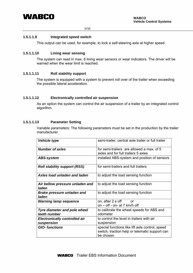
1.5.1.1.13 Parameter Setting
Variable parameters: The following parameters must be set in the production by the trailer manufacturer. Vehicle type
semi-trailer, central axle trailer or full trailer
Number of axles for semi-trailers are allowed a max. of 5 axles and for full trailers 5 axles
ABS-system installed ABS-system and position of sensors
Roll stability support (RSS) for semi-trailers and full trailers
Axles load unladen and laden to adjust the load sensing function
Air bellow pressure unladen and laden
to adjust the load sensing function
Brake pressure unladen and laden
to adjust the load sensing function
Warning lamp sequence on, after 2 s off or on – off - on- at 7 km/h off
Tyre diameter and pole wheel teeth number
to calibrate the wheel speeds for ABS and odometer
Electronically controlled air suspension
to control the level in trailers with air suspension
GIO- functions special functions like lift axle control, speed switch, traction help or telematic support can be chosen
WABCO Vehicle Control Systems 10/58
Trailer EBS Information Document
2. Applications 2.1 List of trailer types and ABS configurations
Single or multi-axle semi-trailer, centre- axle trailers or full trailers of categories O3 and O4 according to Directive 71/320/EEC, with air suspension or mechanical suspension, disc or drum brakes.
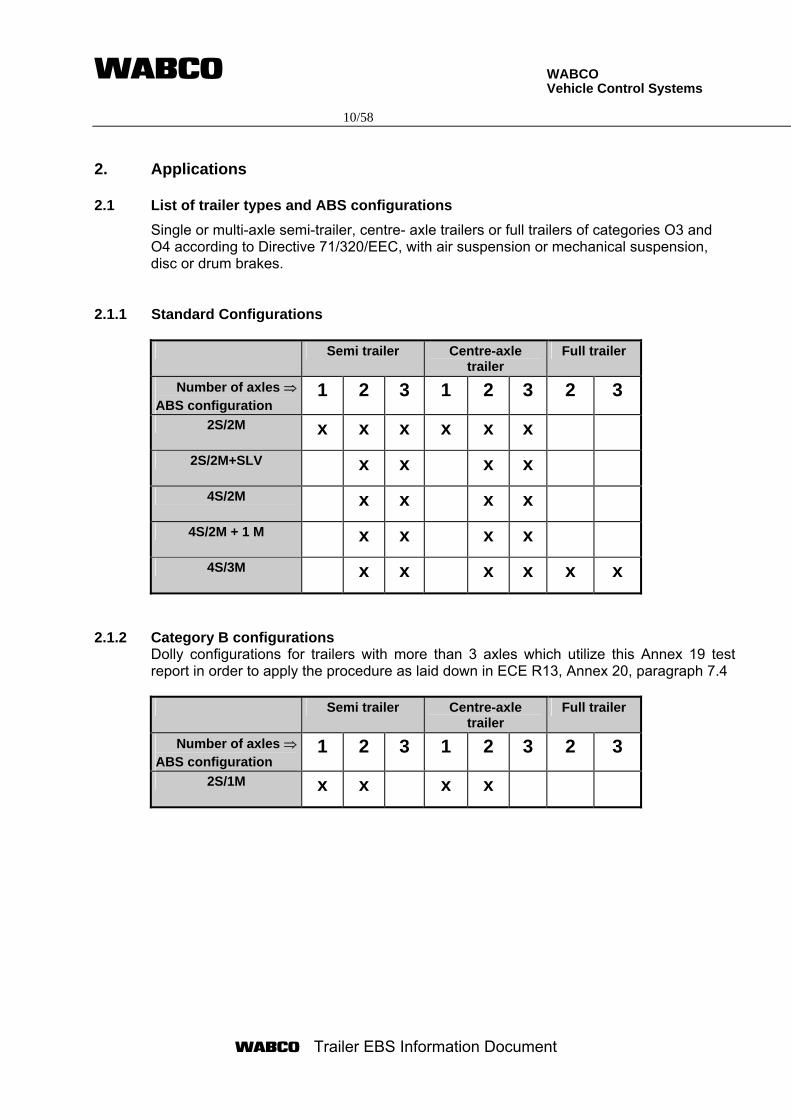
2.1.1 Standard Configurations
Semi trailer Centre-axle trailer
Full trailer
Number of axles ⇒ ABS configuration
1 2 3 1 2 3 2 3
2S/2M x x x x x x
2S/2M+SLV x x x x
4S/2M x x x x
4S/2M + 1 M x x x x
4S/3M x x x x x x
2.1.2 Category B configurations Dolly configurations for trailers with more than 3 axles which utilize this Annex 19 test report in order to apply the procedure as laid down in ECE R13, Annex 20, paragraph 7.4 Semi trailer Centre-axle
trailer Full trailer
Number of axles ⇒ ABS configuration
1 2 3 1 2 3 2 3
2S/1M x x x x
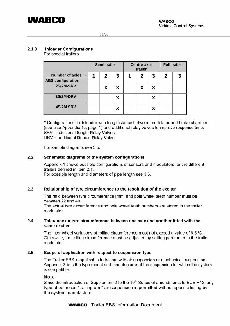
WABCO Vehicle Control Systems 11/58
Trailer EBS Information Document
2.1.3 Inloader Configurations
For special trailers Semi trailer Centre-axle
trailer Full trailer
Number of axles ⇒ ABS configuration
1 2 3 1 2 3 2 3
2S/2M-SRV x x x x
2S/2M-DRV x x
4S/2M SRV x x
* Configurations for Inloader with long distance between modulator and brake chamber (see also Appendix 1c, page 1) and additional relay valves to improve response time. SRV = additional Single Relay Valves DRV = additional Double Relay Valve
For sample diagrams see 3.5.
2.2. Schematic diagrams of the system configurations
Appendix 1 shows possible configurations of sensors and modulators for the different trailers defined in item 2.1. For possible length and diameters of pipe length see 3.6.
2.3 Relationship of tyre circumference to the resolution of the exciter
The ratio between tyre circumference [mm] and pole wheel teeth number must be between 22 and 40. The actual tyre circumference and pole wheel teeth numbers are stored in the trailer modulator.
2.4 Tolerance on tyre circumference between one axle and another fitted with the same exciter
The inter wheel variations of rolling circumference must not exceed a value of 6,5 %. Otherwise, the rolling circumference must be adjusted by setting parameter in the trailer modulator.
2.5 Scope of application with respect to suspension type
The Trailer EBS is applicable to trailers with air suspension or mechanical suspension. Appendix 2 lists the type model and manufacturer of the suspension for which the system is compatible.
Note Since the introduction of Supplement 2 to the 10th Series of amendments to ECE R13, any type of balanced "trailing arm" air suspension is permitted without specific listing by the system manufacturer.
WABCO Vehicle Control Systems 12/58
Trailer EBS Information Document
However, this exemption for trailing arm air suspensions does not yet apply in the case of Annex XIV of Directive 71/320/EEC. Therefore Appendix 2 covers both types of suspension.
2.6 Recommendations on differential brake input torque in relation to the ABS configuration and trailer bogie
For multiple-axle applications an almost identical utilization of friction of these axles is required. If all of the wheels are not fitted with sensors, the axle(s) which usually lock(s) first must be equipped with sensors. Multiple-axle applications having only static axle load proportioning must be equipped in that way that the wheels of all axles reach their locking point simultaneously and that one wheel directly controlled - does not control more than two other wheels or - in the case of central axle trailers does not indirectly control more than one wheel or one axle Differentials on brake input torque are admissible for all anti-lock configurations within a range of 20 %.
2.7 Test data of energy consumption
The energy consumption has been tested according to paragraph 6.1 of annex 10 of 98/12/EG and annex 13 of ECE R 13, respectively. To determine the worst case a variation of axle load has been made. Within a range of ±10,000 N of the worst case, the energy consumption for different ABS configurations has been determined. During all energy consumption tests the load-sensing valve was in a fully laden position. The following diagram represents the data from the energy consumption tests. It gives the supply pressure after ABS control of 15 sec and five additional brake applications. The worst case axle load is 2600 kg.
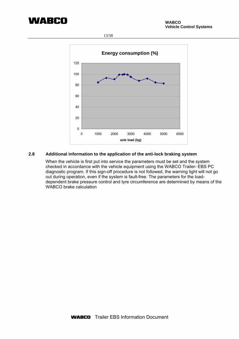
WABCO Vehicle Control Systems 13/58
Trailer EBS Information Document
Energy consumption (%)
0
20
40
60
80
100
120
0 1000 2000 3000 4000 5000 6000
axle load (kg)
2.8 Additional information to the application of the anti-lock braking system
When the vehicle is first put into service the parameters must be set and the system checked in accordance with the vehicle equipment using the WABCO Trailer- EBS PC diagnostic program. If this sign-off procedure is not followed, the warning light will not go out during operation, even if the system is fault-free. The parameters for the load-dependent brake pressure control and tyre circumference are determined by means of the WABCO brake calculation
WABCO Vehicle Control Systems 14/58
Trailer EBS Information Document
3 Component description 3.1 Sensors and exciters 3.1.1 Wheel speed sensors
The sensors transmit the information from the rotating toothed wheels to the trailer modulator. Based on this information the ECU calculates the wheel and vehicle speeds. Special care must be taken to ensure accurate speed information. Identification: Wheel speed sensors: WABCO part number 441 032 ... 0 441 035 … 0 Sensors are mounted in clamp bushings, WABCO part number 899 760 510 4, 899 759 815 4 or 899 759 882 4
3.1.2 Exciters
Exciters according WABCO specification 895 905 000 4
3.1.3 Pressure sensor
The sensor can be used optional as an external driver demand sensor in long vehicles or as an external axle load sensor. Identification: Pressure sensor: WABCO No. 441 040 007 0 to 441 040 015 0 441 044 0010 and 441 044 002 0
3.1.4 Levelling sensor
The sensor can be used in systems with integrated electronically controlled air suspension (Premium variant) and in trailers with mechanical suspension to measure the axle load. Identification: Levelling sensor WABCO No. 441 050 1.. 0 .
WABCO Vehicle Control Systems 15/58
Trailer EBS Information Document
3.2 Controllers 3.2.1 Trailer modulator
The trailer modulator (TM) serves to control and monitor the electro-pneumatic braking system. The TM is installed in the braking system between the reservoir, relay emergency valve and the brake cylinders. It controls the brake cylinder pressure on both sides of one, two or three axles. The TM communicates directly or via TCE (Trailer Central Electronic see 3.2.2) using the extended ISO 7638 connector with the motor vehicle via the electric trailer interface according ISO 11992. The TM has two pneumatically independent pressure control circuits, each with a supply and exhaust valve, redundancy valve, pressure sensor and common control electronics. The required deceleration of the vehicle is determined from the pressure signal received from the CAN demand value. The TM has an integrated axle load sensor. If necessary an external demand sensor and axle load sensor can be connected. The TM has also a connector for lining wear sensor(s). The brake force is modified as a function of the vehicle load (brake force distribution function). In addition the wheel speeds are registered and analysed via up to four rotary speed sensors. If there is a locking tendency the braking pressure specified for the brake cylinder is controlled by the ABS control circuit. The TM has an electrical connection for the ABS or EBS relay valve. With this connection, it is possible to control the brake pressure of an axle separately. In the TM the reservoir pressure is sensed so that the driver can be warned if there is any pressure loss.
The TM has two delivery ports which are designated 2.1 and 2.2. The maximum delivery volume per delivering port is 3 x Type 30” or equivalent volume. There two variants available. The Standard variant covers only 2S/2M applications, whereas the Premium variant covers all applications and in addition includes the electronically controlled air suspension. Identification:
Trailer modulator: WABCO No. Standard variant: 480 102 030 0 – 480 102 058 0 480 102 030 7 – 480 102 058 7 480 102 030 R – 480 102 058 R
Premium variant: 480 102 060 0 – 480 102 088 0 480 102 060 7 – 480 102 088 7 480 102 060 R – 480 102 088 R
Failure modes:
The TM monitors itself. In the event of a fault, any parts found to be defective (ECU, sensors, modulator(s)) are selectively switched off, and the warning system is actuated. Even in the event of the whole system being switched off the back-up braking function is maintained but without load-dependent brake force control and without ABS function. In the case of stoplight-powering only ABS and the load-dependent brake force control are in function with reduced performance. Correct electrical/electronic function of the EBS is indicated by warning device in the driver's cab of towing vehicle according to the provisions of the ECE R13 Section 5.2.1.29. Additional features: • integrated speed switch • automatic lift-axle control
WABCO Vehicle Control Systems 16/58
Trailer EBS Information Document
• integrated load proportioning function • Roll stability control • Lining wear sensing • Integrated electronically controlled air suspension
3.2.2 Trailer Central Electronic
The Trailer Central Electronic (TCE) integrates a communication gateway and power distribution facilities for brake and running gear equipment as well as for equipment other than brake and running. Electronically controlled power supply for brake and running gear equipment is provided via the connector according to ISO7638 with the highest priority given to the power supply of the TM. For equipment other than brake and running gear power supply is provided via the connector according to ISO12098. For brake and running gear equipment the tractor-trailer CAN data link in the connector according to ISO7638 is used. For equipment other than brake and running the tractor-trailer CAN data link in the connector according to ISO12098 is used. The TM and other trailer systems are connected to the TCE via a trailer CAN high speed data bus according to ISO11898 with separate physical CAN links. One CAN link is specially assigned for the connection of the TM. In case of a physical CAN link failure the respective link can be switched of individually to maintain communication via the other physical CAN links. Identification:
Trailer Central Electronic: WABCO part number 446 122 ... 0 Failure detection and handling
The TCE is a self-monitoring system. In case of a malfunction, the power supplies and CAN data links of externally connected systems and components can be individually switched of. Detected failures are stored in a non-volatile memory and can be read out by a diagnostic tool via the central diagnostic connector. Additional features:
• Loading ramp approach assistance • Levelling control and lift axle control • Brake lining wear sensing • Vehicle lights control
3.3 Modulators
3.3.1 EBS relay emergency valve
Trailer brake valve with emergency brake function without predominance - with demand sensor to measure the towing vehicle control pressure. Identification: EBS relay emergency valve WABCO part numbers: 971 002 ... 0 400 600 ... 0
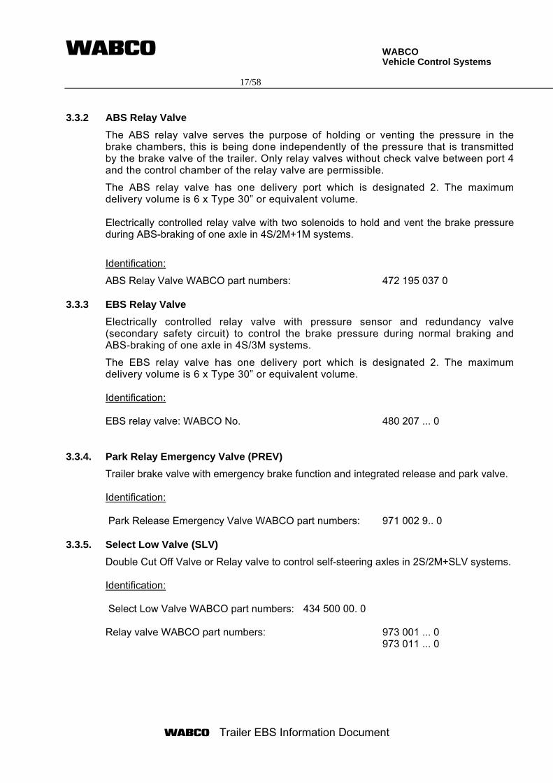
WABCO Vehicle Control Systems 17/58
Trailer EBS Information Document
3.3.2 ABS Relay Valve
The ABS relay valve serves the purpose of holding or venting the pressure in the brake chambers, this is being done independently of the pressure that is transmitted by the brake valve of the trailer. Only relay valves without check valve between port 4 and the control chamber of the relay valve are permissible.
The ABS relay valve has one delivery port which is designated 2. The maximum delivery volume is 6 x Type 30” or equivalent volume. Electrically controlled relay valve with two solenoids to hold and vent the brake pressure during ABS-braking of one axle in 4S/2M+1M systems.
Identification:
ABS Relay Valve WABCO part numbers: 472 195 037 0
3.3.3 EBS Relay Valve
Electrically controlled relay valve with pressure sensor and redundancy valve (secondary safety circuit) to control the brake pressure during normal braking and ABS-braking of one axle in 4S/3M systems.
The EBS relay valve has one delivery port which is designated 2. The maximum delivery volume is 6 x Type 30” or equivalent volume. Identification: EBS relay valve: WABCO No. 480 207 ... 0
3.3.4. Park Relay Emergency Valve (PREV)
Trailer brake valve with emergency brake function and integrated release and park valve. Identification: Park Release Emergency Valve WABCO part numbers: 971 002 9.. 0
3.3.5. Select Low Valve (SLV)
Double Cut Off Valve or Relay valve to control self-steering axles in 2S/2M+SLV systems. Identification: Select Low Valve WABCO part numbers: 434 500 00. 0
Relay valve WABCO part numbers: 973 001 ... 0 973 011 ... 0
WABCO Vehicle Control Systems 18/58
Trailer EBS Information Document
3.3.6. Relay valve
Conventional relay valve to improve time behaviour for Inloaders. Identification: Relay valve: 971 001 … 0 973 011 … 0
3.4 Electrical equipment
The circuit diagrams in appendix 4 shows the connection of all external components (power supply, sensors and modulators). All components are connected via external connectors, which are moulded and coded to avoid mismatching. The cables and connectors fulfil GGVSE resp. ADR requirements (Test report TUEH - TB 2007 - 019.004).
3.4.1 Powering methods
Permanent power supply via the connector according to ISO 7638-2003 (7-pin) Part 1 (24 V) or to ISO 7638-1985 (5-pin) (24 V). In the event of ISO 7638 power supply failure to maintain trailer stability during braking: Intermittent power supply via the connector according to ISO 1185 or ISO 12098. In this case only ABS and the load- dependent brake force control are in function with reduced performance.
3.4.2 Warning lamp sequence
The system can output two different warning lamp sequences. The sequences are according to the provisions of the ECE R13 Section 5.2.1.29 and can be changed by parameter setting. Option 1
When vehicle is stationary:
- Warning light comes on when ignition is switched on.
- Warning light goes off after approx. 2 s if no fault is detected.
- If a fault has been detected e.g. sensor fault, the warning light will stay on.
- If a sensor fault was recorded during the previous journey but is no longer current, the warning light will go off at v ≥ 7 km/h.
When vehicle is travelling at v ≥ 7 km/h:
- Warning light comes on, or stays on, if a current error is detected.
WABCO Vehicle Control Systems 19/58
Trailer EBS Information Document
Option 2
- Warning light comes on when ignition is switched on
- If no current defect has been detected, warning light goes out after about 2 s, lights up again after a further 2 s, and goes out at v > 7 km/h.
- If a current defect is detected, e.g. sensor broken off, the warning light stays on.
ISO 1185 (ISO 12098) powering failure warning:
The provision of powering the trailer braking system from the ISO1185 or ISO 12098 connector is to provide a backup in the event of failure of the power supplied via the ISO 7638 connector and therefore there is no failure warning requirement.
Non-specified faults
Non-specified faults are monitored by a flashing warning lamp. After energising the Trailer EBS the flashing of the yellow signal starts after the normal warning signal sequence was completed. When the vehicle speed increases over 10 km/h the flashing warning signal is terminated.
When a specified failure is present the flashing warning lamp signal is replaced by a non-flashing warning lamp signal.
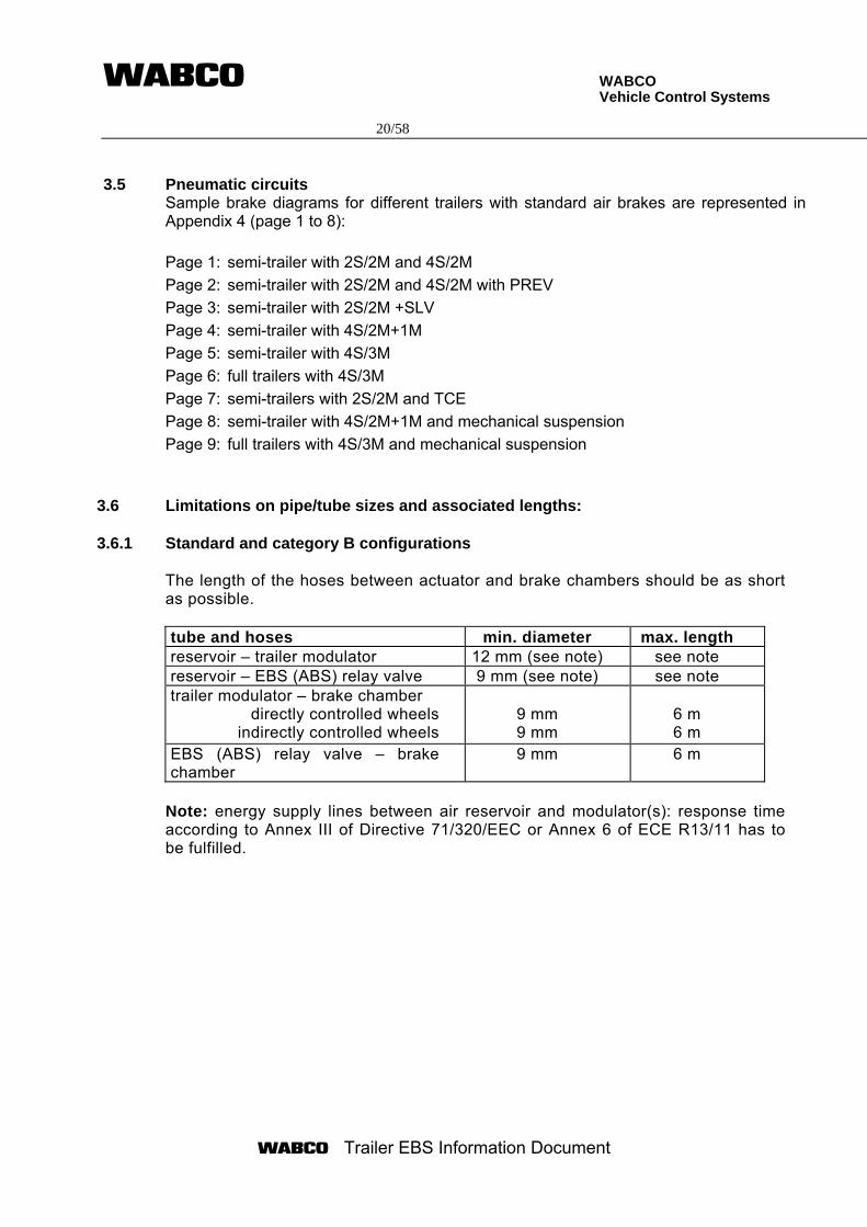
WABCO Vehicle Control Systems 20/58
Trailer EBS Information Document
3.5 Pneumatic circuits
Sample brake diagrams for different trailers with standard air brakes are represented in Appendix 4 (page 1 to 8): Page 1: semi-trailer with 2S/2M and 4S/2M Page 2: semi-trailer with 2S/2M and 4S/2M with PREV Page 3: semi-trailer with 2S/2M +SLV Page 4: semi-trailer with 4S/2M+1M Page 5: semi-trailer with 4S/3M Page 6: full trailers with 4S/3M Page 7: semi-trailers with 2S/2M and TCE Page 8: semi-trailer with 4S/2M+1M and mechanical suspension Page 9: full trailers with 4S/3M and mechanical suspension
3.6 Limitations on pipe/tube sizes and associated lengths:
3.6.1 Standard and category B configurations The length of the hoses between actuator and brake chambers should be as short as possible. tube and hoses min. diameter max. length reservoir – trailer modulator 12 mm (see note) see note reservoir – EBS (ABS) relay valve 9 mm (see note) see note trailer modulator – brake chamber
directly controlled wheels indirectly controlled wheels
9 mm 9 mm
6 m 6 m
EBS (ABS) relay valve – brake chamber
9 mm 6 m
Note: energy supply lines between air reservoir and modulator(s): response time according to Annex III of Directive 71/320/EEC or Annex 6 of ECE R13/11 has to be fulfilled.
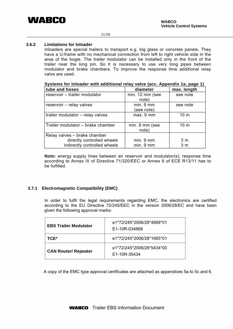
WABCO Vehicle Control Systems 21/58
Trailer EBS Information Document
3.6.2 Limitations for Inloader Inloaders are special trailers to transport e.g. big glass or concrete panels. They have a U-frame with no mechanical connection from left to right vehicle side in the area of the bogie. The trailer modulator can be installed only in the front of the trailer near the king pin. So it is necessary to use very long pipes between modulator and brake chambers. To improve the response time additional relay valve are used. Systems for Inloader with additional relay valve (acc. Appendix 1a, page 1) tube and hoses diameter max. length reservoir – trailer modulator min. 12 mm (see
note) see note
reservoir – relay valves min. 9 mm (see note)
see note
trailer modulator – relay valves max. 9 mm 10 m
Trailer modulator – brake chamber
min. 9 mm (see note)
10 m
Relay valves – brake chamber directly controlled wheels
indirectly controlled wheels
min. 9 mm min. 9 mm
3 m 3 m
Note: energy supply lines between air reservoir and modulator(s): response time according to Annex III of Directive 71/320/EEC or Annex 6 of ECE R13/11 has to be fulfilled.
3.7.1 Electromagnetic Compatibility (EMC)
In order to fulfil the legal requirements regarding EMC, the electronics are certified according to the EU Directive 72/245/EEC in the version 2006/28/EC and have been given the following approval marks:
EBS Trailer Modulator e1*72/245*2006/28*4868*01 E1-10R-034868
TCE* e1*72/245*2006/28*1665*01
CAN Router/ Repeater e1*72/245*2006/28*5434*00 E1-10R-35434
A copy of the EMC type approval certificates are attached as appendices 5a to 5c and 6.
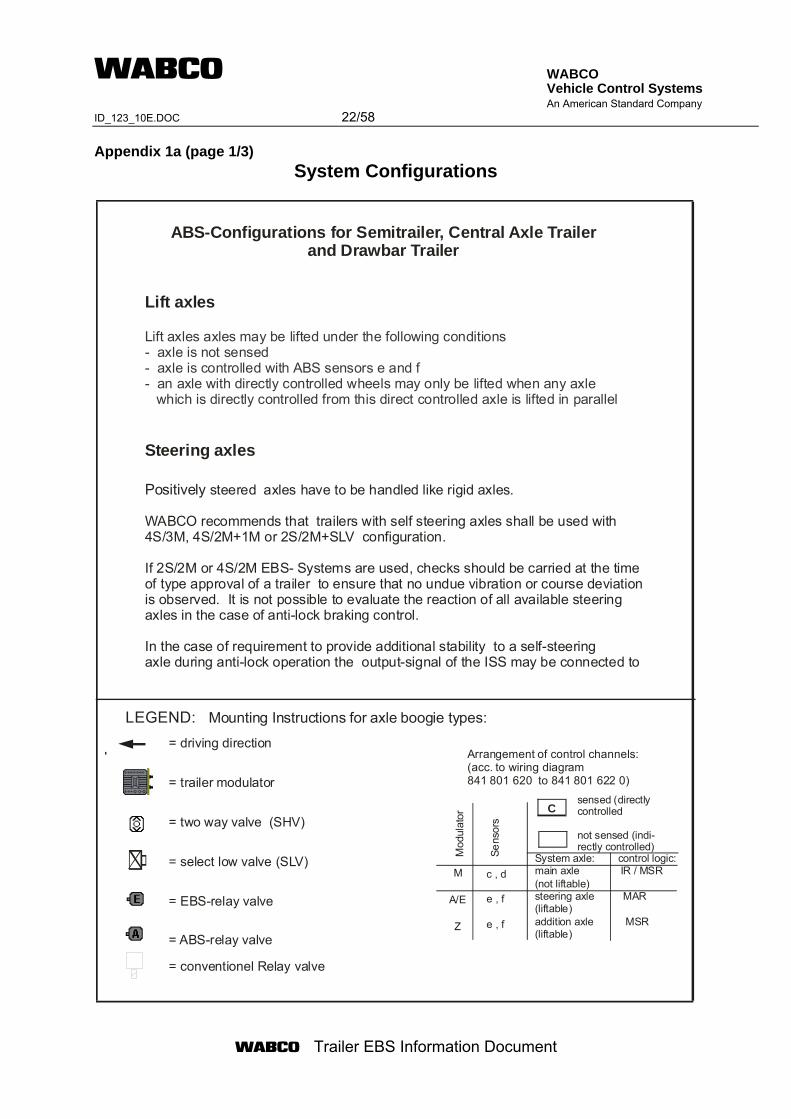
WABCO Vehicle Control Systems An American Standard Company ID_123_10E.DOC 22/58
Trailer EBS Information Document
Appendix 1a (page 1/3)
System Configurations
M
A/E
Z
sensed (directlycontrolled
not sensed (indi-rectly controlled)
System axle: control logic:main axle IR / MSR(not liftable)steering axle MAR(liftable)addition axle MSR(liftable)
Mod
ulat
or
Sens
ors
c , d
e , f
e , f
C
Positively
Lift axles
Steering axles
steered axles have to be handled like rigid axles.
WABCO recommends that trailers with self steering axles shall be used with 4S/3M, 4S/2M+1M or 2S/2M+SLV configuration.
If 2S/2M or 4S/2M EBS- Systems are used, checks should be carried at the time of type approval of a trailer to ensure that no undue vibration or course deviation is observed. It is not possible to evaluate the reaction of all available steering axles in the case of anti-lock braking control.
In the case of requirement to provide additional stability to a self-steering axle during anti-lock operation the output-signal of the ISS may be connected to
Lift axles axles may be lifted under the following conditions- axle is not sensed- axle is controlled with ABS sensors e and f- an axle with directly controlled wheels may only be lifted when any axle which is directly controlled from this direct controlled axle is lifted in parallel
= driving direction
= trailer modulator
= two way valve (SHV)
= select low valve (SLV)
= EBS-relay valve
= ABS-relay valve
= conventionel Relay valve
LEGEND: Mounting Instructions for axle boogie types:
Arrangement of control channels:(acc. to wiring diagram841 801 620 to 841 801 622 0)
ABS-Configurations for Semitrailer, Central Axle Trailer and Drawbar Trailer
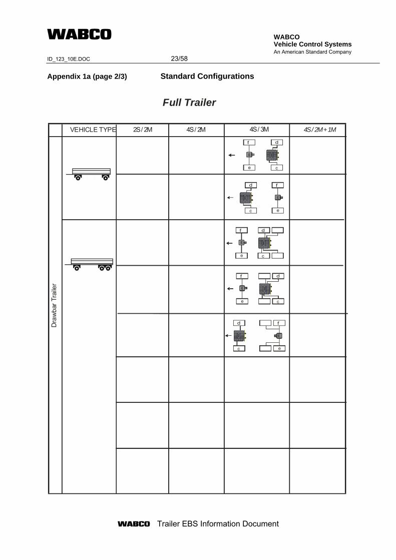
WABCO Vehicle Control Systems An American Standard Company ID_123_10E.DOC 23/58
Trailer EBS Information Document
Appendix 1a (page 2/3) Standard Configurations
Dra
wba
r Tra
iler
2S / 2M 4S / 2M 4S / 3M 4S / 2M + 1MVEHICLE TYPE
Full Trailer
d
c
f
e
E
d
c
f
e
E
d
c
f
e
E
d
c
f
e
E
d
c
f
e
E
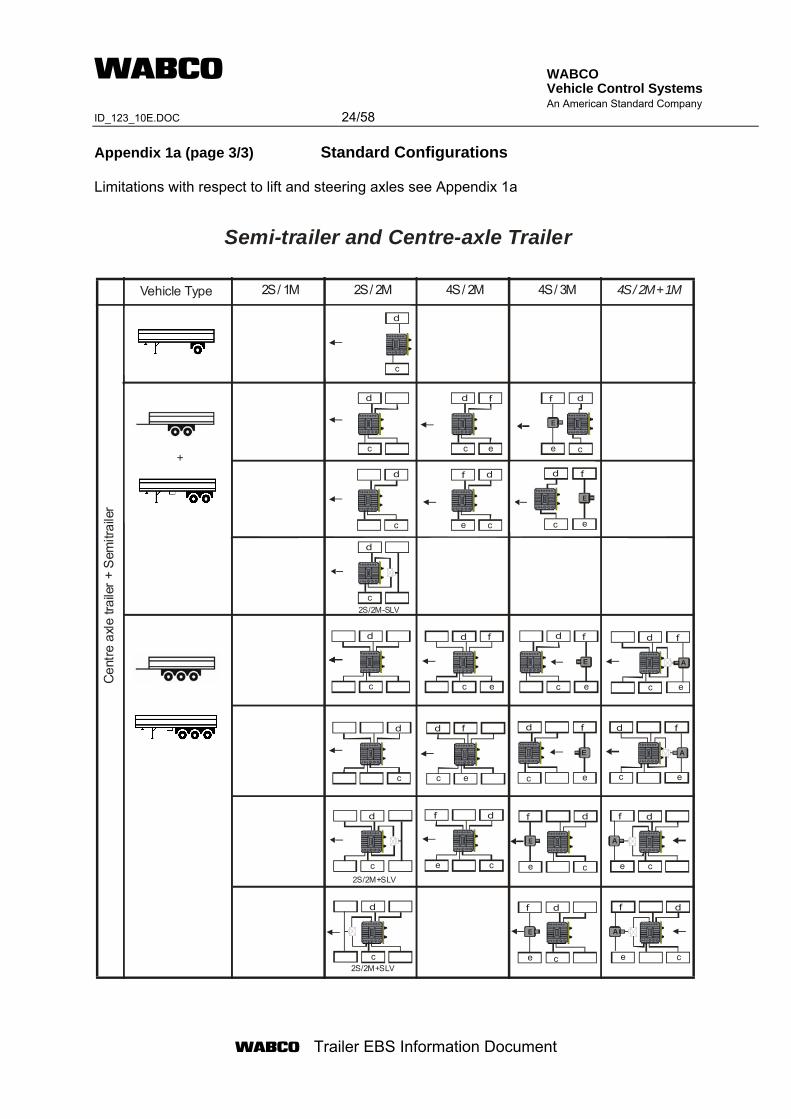
WABCO Vehicle Control Systems An American Standard Company ID_123_10E.DOC 24/58
Trailer EBS Information Document
Appendix 1a (page 3/3) Standard Configurations Limitations with respect to lift and steering axles see Appendix 1a
+
2S / 1M 2S / 2M 4S / 2M 4S / 3M 4S / 2M + 1MVehicle Type
Cen
tre a
xle
traile
r + S
emitr
aile
r
Semi-trailer and Centre-axle Trailer
2S/2M+SLV
2S/2M-SLV
2S/2M+SLV
d
c
d
c
d
c
f
e
d
c
d
c
f
e
d
c
d
c
d
c
d
c
f
e
d
c
f
e
d
c
f
e
E
d
c
f
e
E
d
c
f
e
d
c
d
c
d
c
f
e
E
d
c
A
f
e
d
c
A
f
e
d
c
f
e
A
d
c
f
e
A
d
c
f
e
E
d
c
f
e
E
d
c
f
e
E
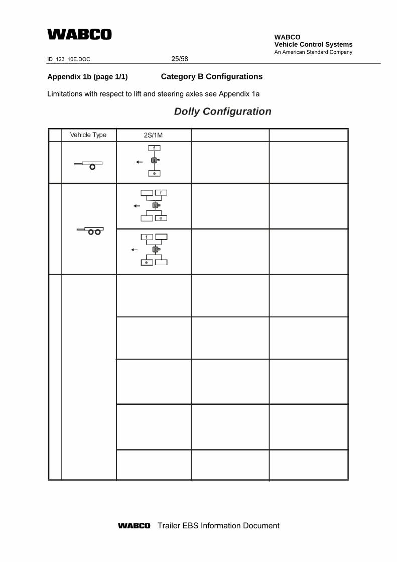
WABCO Vehicle Control Systems An American Standard Company ID_123_10E.DOC 25/58
Trailer EBS Information Document
Appendix 1b (page 1/1) Category B Configurations Limitations with respect to lift and steering axles see Appendix 1a
Vehicle Type 2S/1M
Dolly Configuration
f
e
E
f
e
E
f
e
E
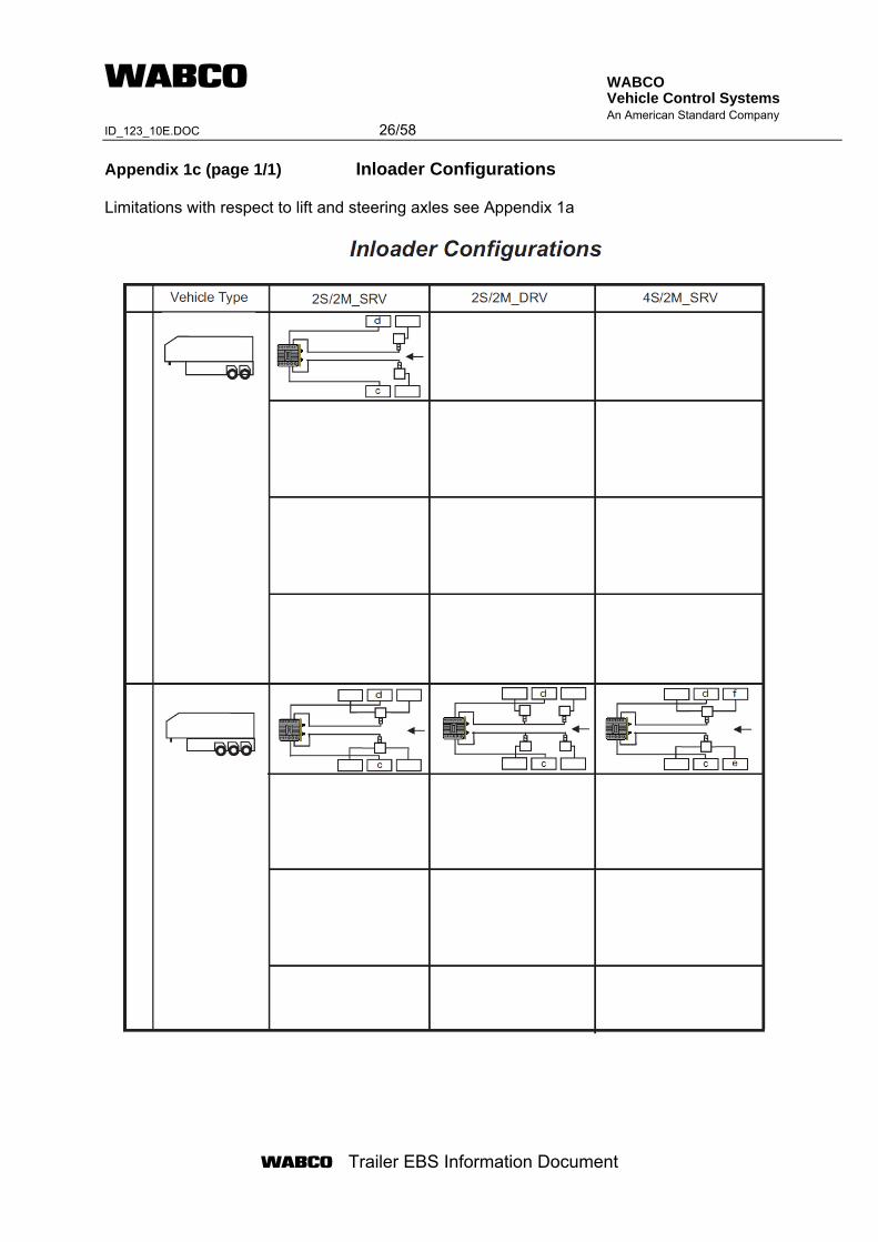
WABCO Vehicle Control Systems An American Standard Company ID_123_10E.DOC 26/58
Trailer EBS Information Document
Appendix 1c (page 1/1) Inloader Configurations Limitations with respect to lift and steering axles see Appendix 1a
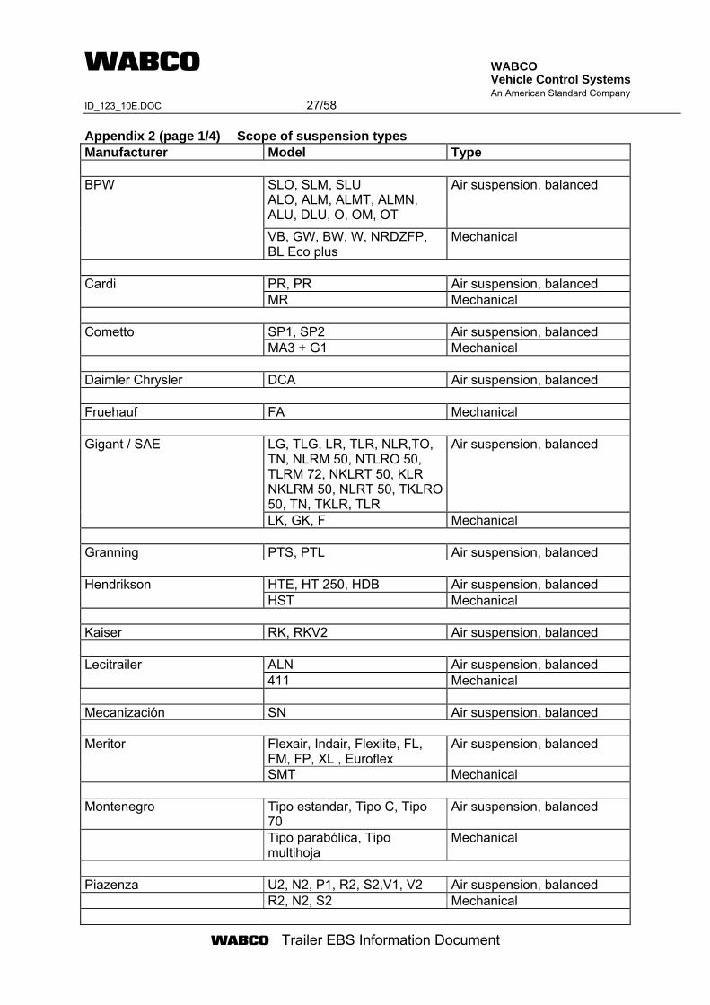
WABCO Vehicle Control Systems An American Standard Company ID_123_10E.DOC 27/58
Trailer EBS Information Document
Appendix 2 (page 1/4) Scope of suspension types Manufacturer Model Type
SLO, SLM, SLU ALO, ALM, ALMT, ALMN, ALU, DLU, O, OM, OT
Air suspension, balanced BPW
VB, GW, BW, W, NRDZFP, BL Eco plus
Mechanical
PR, PR Air suspension, balanced Cardi MR Mechanical
SP1, SP2 Air suspension, balanced Cometto MA3 + G1 Mechanical
Daimler Chrysler DCA Air suspension, balanced Fruehauf FA Mechanical
LG, TLG, LR, TLR, NLR,TO, TN, NLRM 50, NTLRO 50, TLRM 72, NKLRT 50, KLR NKLRM 50, NLRT 50, TKLRO 50, TN, TKLR, TLR
Air suspension, balanced Gigant / SAE
LK, GK, F Mechanical Granning PTS, PTL Air suspension, balanced
HTE, HT 250, HDB Air suspension, balanced Hendrikson HST Mechanical
Kaiser RK, RKV2 Air suspension, balanced
ALN Air suspension, balanced Lecitrailer 411 Mechanical
Mecanización SN Air suspension, balanced
Flexair, Indair, Flexlite, FL, FM, FP, XL , Euroflex
Air suspension, balanced Meritor
SMT Mechanical Montenegro Tipo estandar, Tipo C, Tipo
70 Air suspension, balanced
Tipo parabólica, Tipo multihoja
Mechanical
Piazenza U2, N2, P1, R2, S2,V1, V2 Air suspension, balanced R2, N2, S2 Mechanical
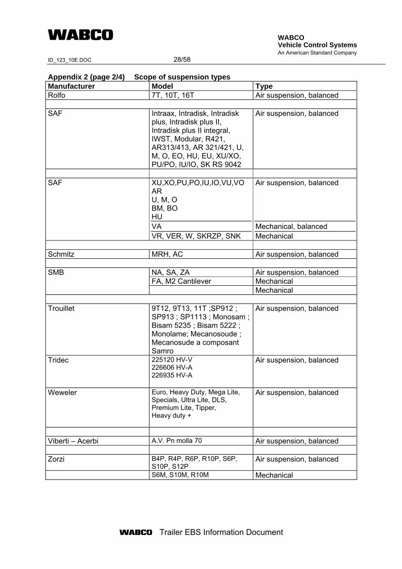
WABCO Vehicle Control Systems An American Standard Company ID_123_10E.DOC 28/58
Trailer EBS Information Document
Appendix 2 (page 2/4) Scope of suspension types Manufacturer Model Type Rolfo 7T, 10T, 16T Air suspension, balanced SAF Intraax, Intradisk, Intradisk
plus, Intradisk plus II, Intradisk plus II integral, IWST, Modular, R421, AR313/413, AR 321/421, U, M, O, EO, HU, EU, XU/XO, PU/PO, IU/IO, SK RS 9042
Air suspension, balanced
SAF XU,XO,PU,PO,IU,IO,VU,VO
AR U, M, O BM, BO HU VA VR, VER, W, SKRZP, SNK
Air suspension, balanced Mechanical, balanced Mechanical
Schmitz MRH, AC Air suspension, balanced
NA, SA, ZA Air suspension, balanced FA, M2 Cantilever Mechanical
SMB
Mechanical Trouillet 9T12, 9T13, 11T ;SP912 ;
SP913 ; SP1113 ; Monosam ; Bisam 5235 ; Bisam 5222 ; Monolame; Mecanosoude ; Mecanosude a composant Samro
Air suspension, balanced
Tridec 225120 HV-V 226606 HV-A 226935 HV-A
Air suspension, balanced
Weweler Euro, Heavy Duty, Mega Lite, Specials, Ultra Lite, DLS, Premium Lite, Tipper, Heavy duty +
Air suspension, balanced
Viberti – Acerbi A.V. Pn molla 70 Air suspension, balanced Zorzi B4P, R4P, R6P, R10P, S6P,
S10P, S12P Air suspension, balanced
S6M, S10M, R10M Mechanical
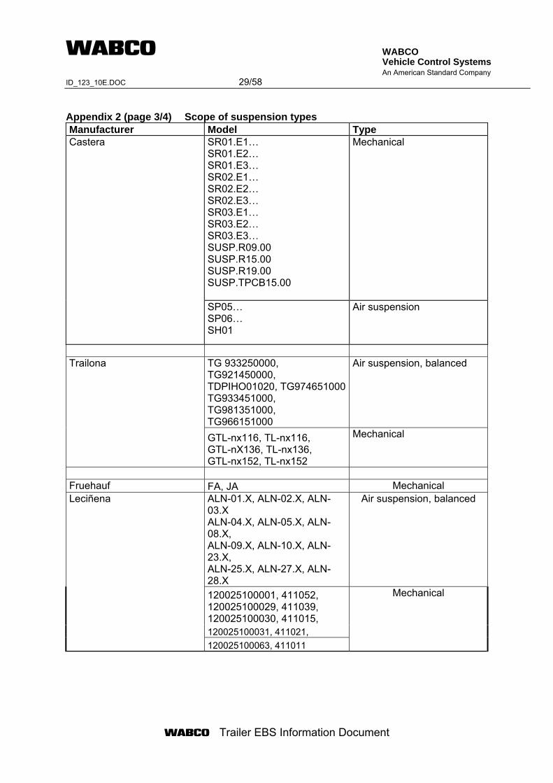
WABCO Vehicle Control Systems An American Standard Company ID_123_10E.DOC 29/58
Trailer EBS Information Document
Appendix 2 (page 3/4) Scope of suspension types Manufacturer Model Type
SR01.E1… SR01.E2… SR01.E3… SR02.E1… SR02.E2… SR02.E3… SR03.E1… SR03.E2… SR03.E3… SUSP.R09.00 SUSP.R15.00 SUSP.R19.00 SUSP.TPCB15.00
Mechanical Castera
SP05… SP06… SH01
Air suspension
TG 933250000, TG921450000, TDPIHO01020, TG974651000TG933451000, TG981351000, TG966151000
Air suspension, balanced Trailona
GTL-nx116, TL-nx116, GTL-nX136, TL-nx136, GTL-nx152, TL-nx152
Mechanical
Fruehauf FA, JA Mechanical
ALN-01.X, ALN-02.X, ALN-03.X ALN-04.X, ALN-05.X, ALN-08.X, ALN-09.X, ALN-10.X, ALN-23.X, ALN-25.X, ALN-27.X, ALN-28.X
Air suspension, balanced
120025100001, 411052, 120025100029, 411039, 120025100030, 411015, 120025100031, 411021,
Leciñena
120025100063, 411011
Mechanical
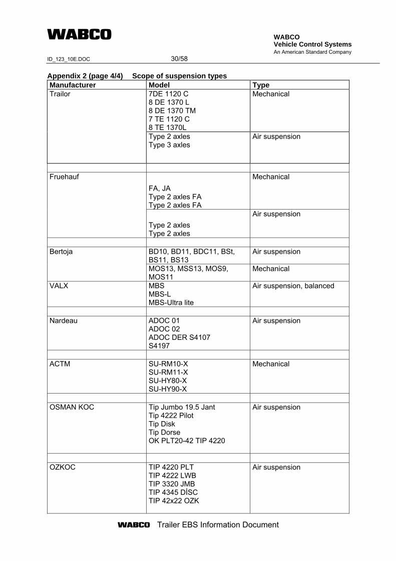
WABCO Vehicle Control Systems An American Standard Company ID_123_10E.DOC 30/58
Trailer EBS Information Document
Appendix 2 (page 4/4) Scope of suspension types Manufacturer Model Type
7DE 1120 C 8 DE 1370 L 8 DE 1370 TM 7 TE 1120 C 8 TE 1370L
Mechanical Trailor
Type 2 axles Type 3 axles
Air suspension
FA, JA Type 2 axles FA Type 2 axles FA
Mechanical Fruehauf
Type 2 axles Type 2 axles
Air suspension
BD10, BD11, BDC11, BSt, BS11, BS13
Air suspension Bertoja
MOS13, MSS13, MOS9, MOS11
Mechanical
VALX MBS MBS-L MBS-Ultra lite
Air suspension, balanced
Nardeau ADOC 01
ADOC 02 ADOC DER S4107 S4197
Air suspension
ACTM
SU-RM10-X SU-RM11-X SU-HY80-X SU-HY90-X
Mechanical
OSMAN KOC Tip Jumbo 19.5 Jant
Tip 4222 Pilot Tip Disk Tip Dorse OK PLT20-42 TIP 4220
Air suspension
OZKOC TIP 4220 PLT
TIP 4222 LWB TIP 3320 JMB TIP 4345 DİSC TIP 42x22 OZK
Air suspension
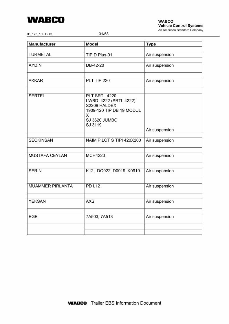
WABCO Vehicle Control Systems An American Standard Company ID_123_10E.DOC 31/58
Trailer EBS Information Document
Manufacturer Model Type
TURMETAL TIP D Plus-01 Air suspension AYDIN
DB-42-20
Air suspension
AKKAR
PLT TIP 220
Air suspension
SERTEL PLT SRTL 4220
LWBD 4222 (SRTL 4222) S2209 HALDEX 1909-120 TIP DB 19 MODUL X SJ 3620 JUMBO SJ 3119 Air suspension
SECKINSAN
NAIM PILOT S TIPI 420X200
Air suspension
MUSTAFA CEYLAN
MCH4220
Air suspension
SERIN
K12, DO922, D0919, K0919
Air suspension
MUAMMER PIRLANTA
PD L12
Air suspension
YEKSAN
AXS
Air suspension
EGE
7A503, 7A513
Air suspension
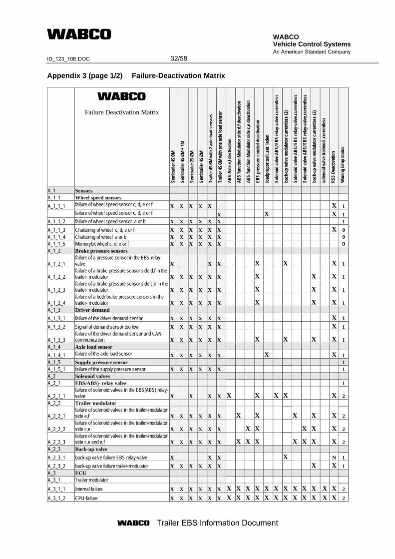
WABCO Vehicle Control Systems An American Standard Company ID_123_10E.DOC 32/58
Trailer EBS Information Document
Appendix 3 (page 1/2) Failure-Deactivation Matrix
Failure Deactivation Matrix
Sem
itrail
er 4S
/3M
Sem
itrail
er 4S
/2M +
1M
Sem
itrail
er 2S
/2M
Sem
itrail
er 4S
/2M
Trail
er 4S
/3M w
ith 2
axle
load
sens
ors
Trail
er 4S
/3M w
ith o
ne ax
le lo
ad se
nsor
ABS-
Axle
e,f d
ectiv
atio
n
ABS
func
tion
Modu
lator
side
d,f
deac
tivat
ion
ABS
func
tion
Modu
lator
side
c,e d
eact
ivatio
n
EBS
pres
sure
conz
tol d
eact
ivatio
n
load
prop
or.tr
ail..s
et la
den
Solen
oid
valve
ABS
/ EBS
relay
-valv
e.cur
rent
less
back
-up
valve
mod
ulat
or cu
rrent
less (
2)
Solen
oid
valve
ABS
/ EBS
relay
-valv
e.cur
rent
less
Solen
oid
valve
ABS
/ EBS
relay
-valv
e.cur
rent
less
back
-up
valve
mod
ulat
or cu
rrent
less (
2)
solen
oid
valve
trail
mod
.cur
rent
less
RSS
Deac
tivat
ion
Wan
ing
lamp
stat
us
A_1 Sensors A_1_1 Wheel speed sensors
A_1_1_1 failure of wheel speed sensor c, d, e or f X X X X X X 1
failure of wheel speed sensor c, d, e or f X X X 1 A_1_1_2 failure of wheel speed sensor a or b X X X X X X 1
A_1_1_3 Chattering of wheel c, d, e or f X X X X X X X 0 A_1_1_4 Chattering of wheel a or b X X X X X X 0 A_1_1_5 Memorybit wheel c, d, e or f X X X X X X 0 A_1_2 Brake pressure sensors
A_1_2_1 failure of a pressure sensor in the EBS relay-valve X X X X X X 1
A_1_2_2 failure of a brake pressure sensor side d,f in the trailer- modulator X X X X X X X X X 1
A_1_2_3 failure of a brake pressure sensor side c,d in the trailer- modulator X X X X X X X X X 1
A_1_2_4 failure of a both brake pressure sensors in the trailer- modulator X X X X X X X X X 1
A_1_3 Driver demand
A_1_3_1 failure of the driver demand sensor X X X X X X X 1
A_1_3_2 Signal of demand sensor too low X X X X X X X 1
A_1_3_3 failure of the driver demand sensor and CAN-communication X X X X X X X X X X 1
A_1_4 Axle load sensor
A_1_4_1 failure of the axle load sensor X X X X X X X X 1 A_1_5 Supply pressure sensor 1 A_1_5_1 failure of the supply pressure sensor X X X X X X 1 A_2 Solenoid valves A_2_1 EBS/ABS)- relay valve 1
A_2_1_1 failure of solenoid valves in the EBS(ABS) relay-valve X X X X X X X X X 2
A_2_2 Trailer modulator
A_2_2_1 failure of solenoid valves in the trailer-modulator side e,f X X X X X X X X X X X 2
A_2_2_2 failure of solenoid valves in the trailer-modulator side c,e X X X X X X X X X X X 2
A_2_2_3 failure of solenoid valves in the trailer-modulator side c,e and e,f X X X X X X X X X X X X X 2
A_2_3 Back-up valve
A_2_3_1 back-up valve failure EBS relay-valve X X X X N 1
A_2_3_2 back-up valve failure trailer-modulator X X X X X X X X 1 A_3 ECU A_3_1 Trailer modulator
A_3_1_1 Internal failure X X X X X X X X X X X X X X X X X X 2
A_3_1_2 CPU-failure X X X X X X X X X X X X X X X X X X 2
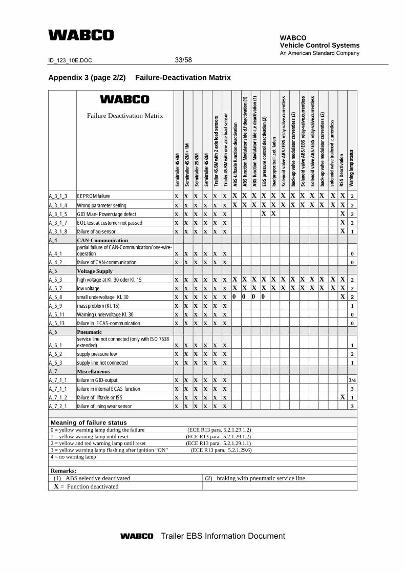
WABCO Vehicle Control Systems An American Standard Company ID_123_10E.DOC 33/58
Trailer EBS Information Document
Appendix 3 (page 2/2) Failure-Deactivation Matrix
Failure Deactivation Matrix
Sem
itrail
er 4S
/3M
Sem
itrail
er 4S
/2M +
1M
Sem
itrail
er 2S
/2M
Sem
itrail
er 4S
/2M
Trail
er 4S
/3M w
ith 2
axle
load
sens
ors
Trail
er 4S
/3M w
ith o
ne ax
le lo
ad se
nsor
ABS-
Lifta
xle fu
nctio
n de
activ
atio
n
ABS
func
tion
Modu
lator
side
d,f
deac
tivat
ion
(1)
ABS
func
tion
Modu
lator
side
c,e d
eact
ivatio
n (1
)
EBS
pres
sure
cont
rol d
eact
ivatio
n (2
)
load
prop
or.tr
ail..s
et la
den
Solen
oid
valve
ABS
/ EBS
relay
-valv
e.cur
rent
less
back
-up
valve
mod
ulat
or cu
rrent
less (
2)
Solen
oid
valve
ABS
/ EBS
relay
-valv
e.cur
rent
less
Solen
oid
valve
ABS
/ EBS
relay
-valv
e.cur
rent
less
back
-up
valve
mod
ulat
or cu
rrent
less (
2)
solen
oid
valve
trail
mod
.cur
rent
less
RSS
Deac
tivat
ion
Wan
ing
lamp
stat
us
A_3_1_3 EEPROM failure X X X X X X X X X X X X X X X X X X 2
A_3_1_4 Wrong parameter setting X X X X X X X X X X X X X X X X X X 2
A_3_1_5 GIO Mian- Powerstage defect X X X X X X X X X 2
A_3_1_7 EOL test at customer not passed X X X X X X X 2
A_3_1_8 failure of aq-sensor X X X X X X X 1
A_4 CAN-Communication
A_4_1 partial failure of CAN-Communication/ one-wire-operation X X X X X X 0
A_4_2 failure of CAN-communication X X X X X X 0
A_5 Voltage Supply A_5_3 high voltage at Kl. 30 oder Kl. 15 X X X X X X X X X X X X X X X X X X 2
A_5_7 low voltage X X X X X X X X X X X X X X X X X X 2
A_5_8 small undervoltage Kl. 30 X X X X X X 0 0 0 0 X 2
A_5_9 massproblem (Kl. 15) X X X X X X 1
A_5_11 Warning undervoltage Kl. 30 X X X X X X 0
A_5_13 failure in ECAS-communication X X X X X X 0
A_6 Pneumatic
A_6_1 service line not connected (only with ISO 7638 extended) X X X X X X 1
A_6_2 supply pressure low X X X X X X 2
A_6_3 supply line not connected X X X X X X 1
A_7 Miscellaneous
A_7_1_1 failure in GIO-output X X X X X X 3/4
A_7_1_1 failure in internal ECAS function X X X X X X 3
A_7_1_2 failure of liftaxle or ISS X X X X X X X 1
A_7_2_1 failure of lining wear sensor X X X X X X 3
Meaning of failure status 0 = yellow warning lamp during the failure (ECE R13 para. 5.2.1.29.1.2) 1 = yellow warning lamp until reset (ECE R13 para. 5.2.1.29.1.2) 2 = yellow and red warning lamp until reset (ECE R13 para. 5.2.1.29.1.1) 3 = yellow warning lamp flashing after ignition “ON” (ECE R13 para. 5.2.1.29.6) 4 = no warning lamp Remarks: (1) ABS selective deactivated (2) braking with pneumatic service line X = Function deactivated
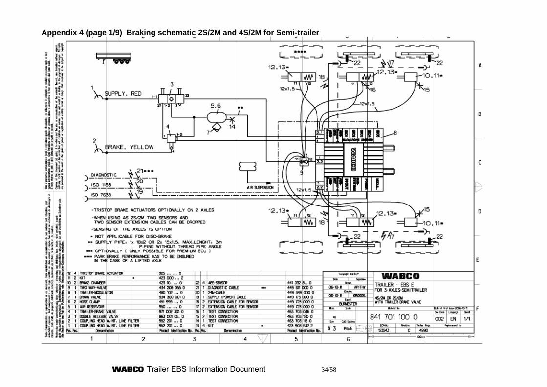
Trailer EBS Information Document 34/58
Appendix 4 (page 1/9) Braking schematic 2S/2M and 4S/2M for Semi-trailer
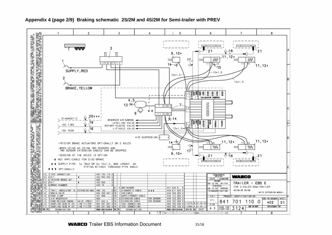
Trailer EBS Information Document 35/58
Appendix 4 (page 2/9) Braking schematic 2S/2M and 4S/2M for Semi-trailer with PREV
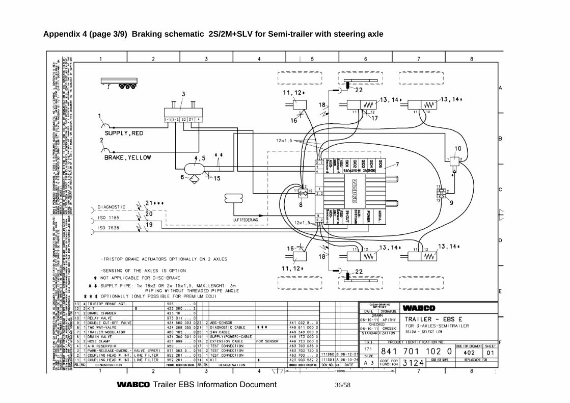
Trailer EBS Information Document 36/58
Appendix 4 (page 3/9) Braking schematic 2S/2M+SLV for Semi-trailer with steering axle
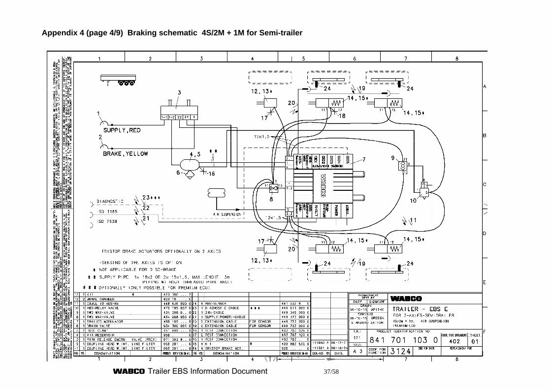
Trailer EBS Information Document 37/58
Appendix 4 (page 4/9) Braking schematic 4S/2M + 1M for Semi-trailer
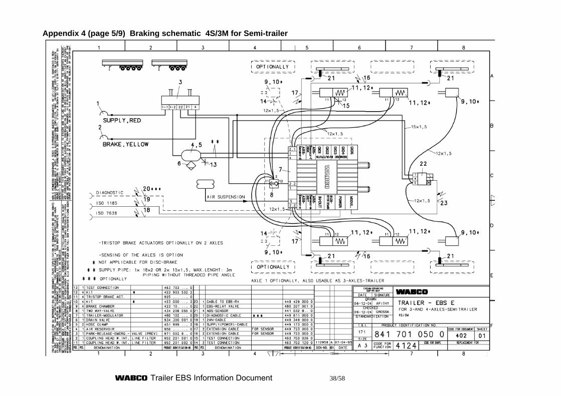
Trailer EBS Information Document 38/58
Appendix 4 (page 5/9) Braking schematic 4S/3M for Semi-trailer
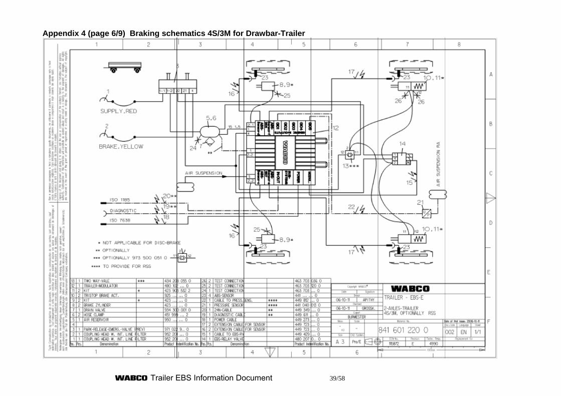
Trailer EBS Information Document 39/58
Appendix 4 (page 6/9) Braking schematics 4S/3M for Drawbar-Trailer
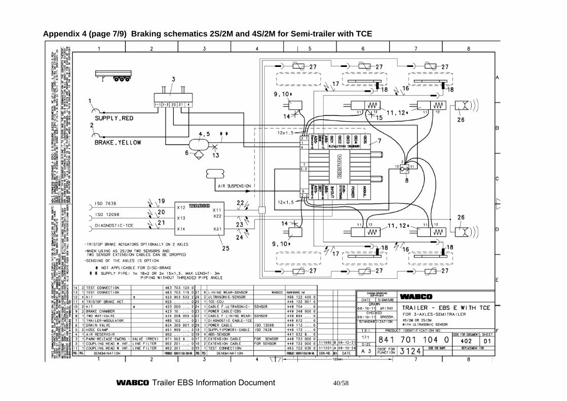
Trailer EBS Information Document 40/58
Appendix 4 (page 7/9) Braking schematics 2S/2M and 4S/2M for Semi-trailer with TCE
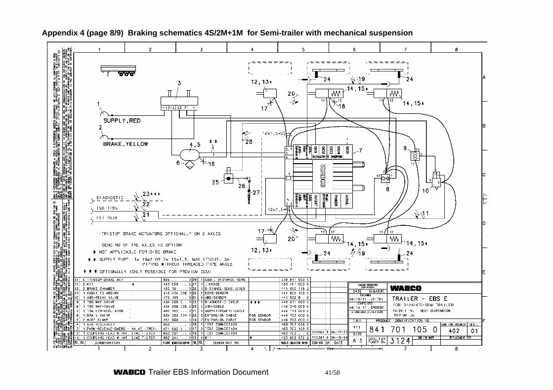
Trailer EBS Information Document 41/58
Appendix 4 (page 8/9) Braking schematics 4S/2M+1M for Semi-trailer with mechanical suspension
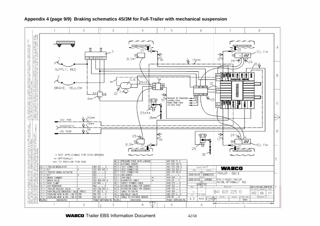
Trailer EBS Information Document 42/58
Appendix 4 (page 9/9) Braking schematics 4S/3M for Full-Trailer with mechanical suspension
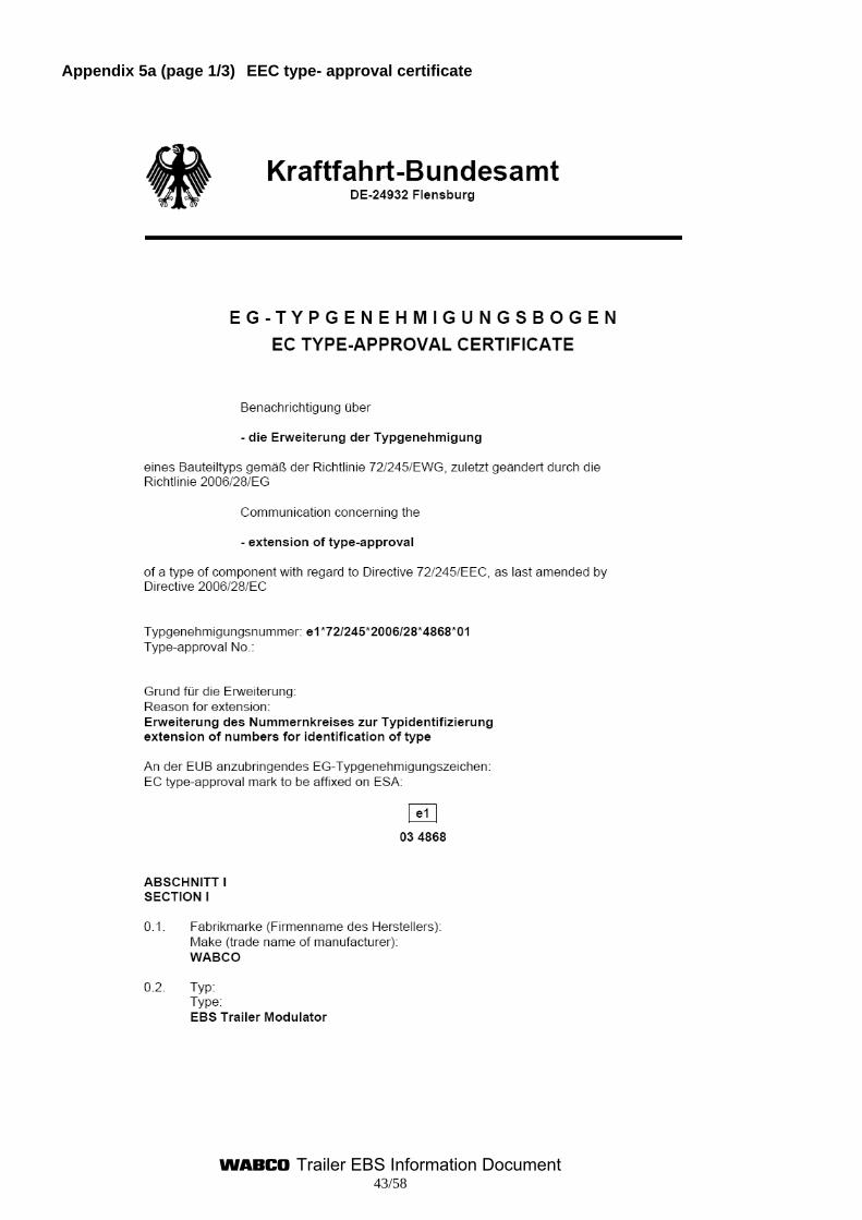
Trailer EBS Information Document 43/58
Appendix 5a (page 1/3) EEC type- approval certificate
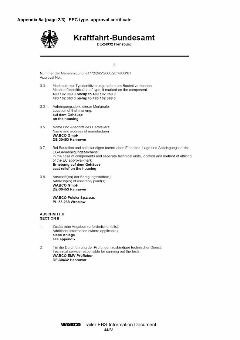
Trailer EBS Information Document 44/58
Appendix 5a (page 2/3) EEC type- approval certificate
Trailer EBS Information Document 45/58
Appendix 5a(page 3/3) EEC type- approval certificate
Trailer EBS Information Document 46/58
Appendix 5b (page 1/3) EEC type- approval certificate for EBS trailer modulator
Trailer EBS Information Document 47/58
Appendix 5b (page 2/3) EEC type- approval certificate for EBS trailer modulator
Trailer EBS Information Document 48/58
Appendix 5b (page 3/3) EEC type- approval certificate for EBS trailer modulator
Trailer EBS Information Document 49/58
Appendix 5c (page 1/3) EEC type- approval certificate for Router/ Repeater
Trailer EBS Information Document 50/58
Appendix 5c (page 2/3) EEC type- approval certificate for Router/ Repeater
Trailer EBS Information Document 51/58
Appendix 5c (page 3/3) EEC type- approval certificate for Router/ Repeater
Trailer EBS Information Document 52/58
Appendix 5d (page 1/3) EEC type- approval certificate for Router/ Repeater
Trailer EBS Information Document 53/58
Appendix 5d (page 2/3) EEC type- approval certificate Router/ Repeater
Trailer EBS Information Document 54/58
Appendix 5d (page 3/3) EEC type- approval certificate
Trailer EBS Information Document 55/58
Appendix 6 (page 1/3) EEC type- approval certificate
Trailer EBS Information Document 56/58
Appendix 6 (page 2/3) EEC type- approval certificate
Trailer EBS Information Document 57/58
Appendix 6 (page 3/3) EEC type- approval certificate
Trailer EBS Information Document 58/58
This side is for technical reasons free

![Kraftfahrt-Bundesamt - Speedline Truck · Kraftfahrt-Bundesamt DE-24932 Flensburg 1XPPHU GHU $%( GDV +HUVWHOOGDWXP 0RQDW -DKU GDV 7\S]HLFKHQ XQG GHU KDOEH 0LWWHQDEVWDQG +0$ E]Z GLH](https://img.pdfslide.org/doc/110x75/5f8f1f5230d11a644c5ff74c/kraftfahrt-bundesamt-speedline-truck-kraftfahrt-bundesamt-de-24932-flensburg-1xpphu.jpg)