Embed Size (px)
Citation preview
Operating Instructions
Attachment Arm E2V
for
Vari-Opal 5 (X), -6 (X), -7 (X), -8 (X) and -9 (X) Vari-EurOpal 5 (X), -7 (X), -8 (X) and -9 (X),
EurOpal 5 (X), -6 (X), -7 (X), -8 (X) and -9 (X) EuroDiamant 8 (X), -9 (X) and -10 (X)
Vari-Diamant 10 (X)
- EN -
Safety is our concern!
Part-No. 175 1425
EN-3/05.02 LEMKEN GmbH & Co. KG
Weseler Straße 5, D-46519 Alpen / Postfach 11 60, D-46515 Alpen Telefon (0 28 02) 81-0, Telefax (0 28 02) 81-220
eMail: [email protected], Internet: http://www.lemken.com

DEFINED USE
• Read and adhere to these „General Health- and Safety precautions“ before putting the power harrow to work!
The attachment arm E2V may only be attached to the Lemken mounted reversible ploughs EurOpal, Vari-Opal, Vari-EurOpal and to the Lemken semi-mounted reversible ploughs EuroDiamant
and Vari-Diamant 10.
• The attachment arm E2V has been designed purely for the cultivation of agricultural soil!
Any use beyond the one stipulated above is no longer considered as defined use. The manufacturer does not accept any responsibility for damages resulting from this; the operator himself carries the full risk!
Under „defined use“ the manufacturer’s prescribed operation-, maintenance- and repair conditions are to be adhered to!
• The attachment arm E2V may only be operated, maintained and repaired by such persons who have been made acquainted with it and who have been advised about the dangers!
• The applicable accident prevention advice as well as the generally accepted safety technical, working, medical and road traffic rules should be adhered to!
• Any damages resulting from unauthorised changes to the machine rule out the responsibility of the manufacturer!
1
CONTENTS
1 MOUNTING....................................................................................................... 3 1.1 Mounted Reversible Ploughs.................................................................. 3 1.2 EuroDiamant 8 and 9 ............................................................................... 4 1.3 EuroDiamant 10 and Vari-Diamant 10 .................................................... 4 1.4 Vari-Opal-series ploughs 100 to 160...................................................... 4
2 GENERAL......................................................................................................... 5
3 ADJUSTMENTS................................................................................................ 5 3.1 Working position (guiding point) ........................................................... 5 3.2 Catching point.......................................................................................... 6 3.3 Adaption of the catch arm length of the furrow press ......................... 7
4 ATTACHMENT TO VARI-EUROPAL PLOUGHS............................................. 8
5 ATTACHMENT TO VARI-OPAL PLOUGHS .................................................... 9
6 PLOUGHING WITHOUT PRESS.................................................................... 10
7 TRANSPORT .................................................................................................. 10
8 FAULT, REASON, REMEDY .......................................................................... 11
9 TABLE OF ASSEMBLIES .............................................................................. 12
10 SAFETY INSTRUCTIONS............................................................................ 13
2
3
1 MOUNTING
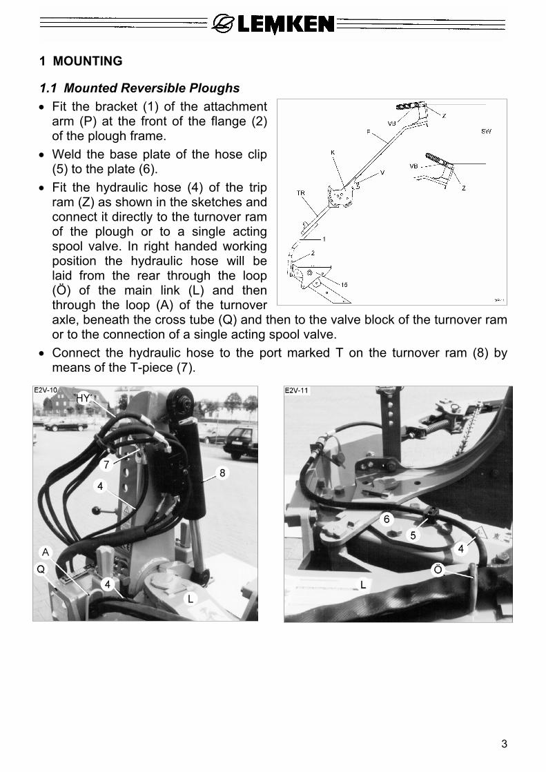
1.1 Mounted Reversible Ploughs • Fit the bracket (1) of the attachment
arm (P) at the front of the flange (2) of the plough frame.
• Weld the base plate of the hose clip (5) to the plate (6).
• Fit the hydraulic hose (4) of the trip ram (Z) as shown in the sketches and connect it directly to the turnover ram of the plough or to a single acting spool valve. In right handed working position the hydraulic hose will be laid from the rear through the loop (Ö) of the main link (L) and then through the loop (A) of the turnover axle, beneath the cross tube (Q) and then to the valve block of the turnover ram or to the connection of a single acting spool valve.
• Connect the hydraulic hose to the port marked T on the turnover ram (8) by means of the T-piece (7).
4
1.2 EuroDiamant 8 and 9
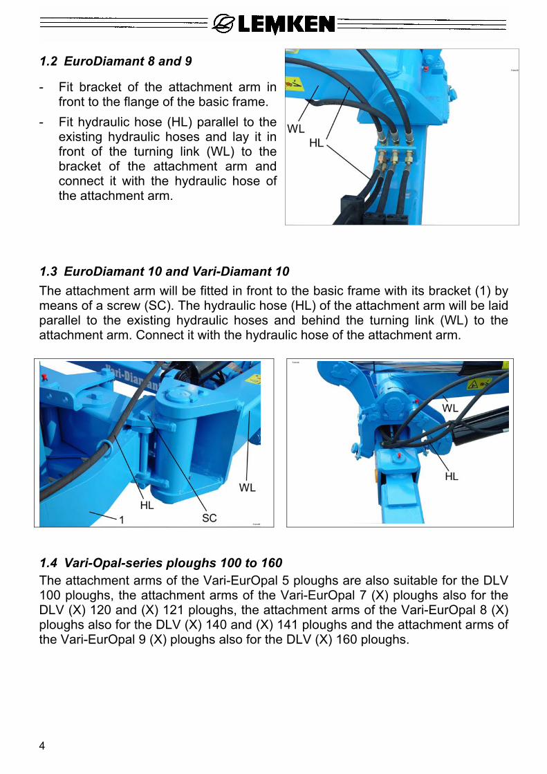
- Fit bracket of the attachment arm in front to the flange of the basic frame.
- Fit hydraulic hose (HL) parallel to the existing hydraulic hoses and lay it in front of the turning link (WL) to the bracket of the attachment arm and connect it with the hydraulic hose of the attachment arm.
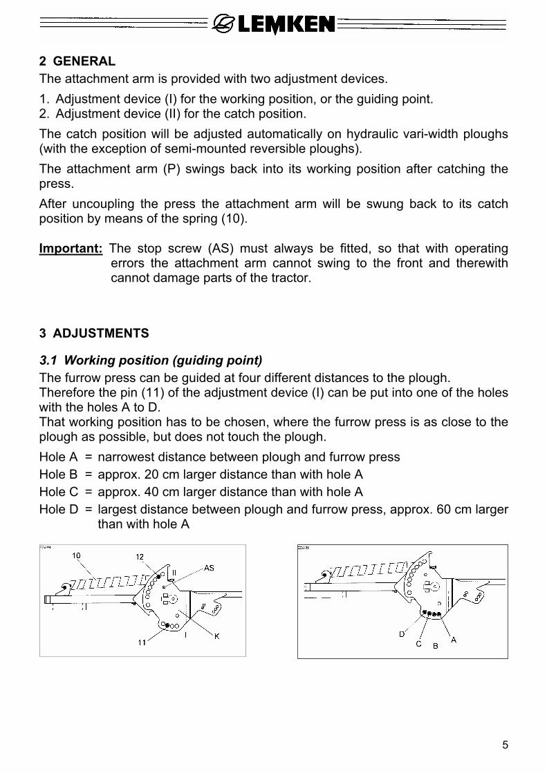
1.3 EuroDiamant 10 and Vari-Diamant 10 The attachment arm will be fitted in front to the basic frame with its bracket (1) by means of a screw (SC). The hydraulic hose (HL) of the attachment arm will be laid parallel to the existing hydraulic hoses and behind the turning link (WL) to the attachment arm. Connect it with the hydraulic hose of the attachment arm.
1.4 Vari-Opal-series ploughs 100 to 160 The attachment arms of the Vari-EurOpal 5 ploughs are also suitable for the DLV 100 ploughs, the attachment arms of the Vari-EurOpal 7 (X) ploughs also for the DLV (X) 120 and (X) 121 ploughs, the attachment arms of the Vari-EurOpal 8 (X) ploughs also for the DLV (X) 140 and (X) 141 ploughs and the attachment arms of the Vari-EurOpal 9 (X) ploughs also for the DLV (X) 160 ploughs.
5
2 GENERAL The attachment arm is provided with two adjustment devices. 1. Adjustment device (I) for the working position, or the guiding point. 2. Adjustment device (II) for the catch position. The catch position will be adjusted automatically on hydraulic vari-width ploughs (with the exception of semi-mounted reversible ploughs). The attachment arm (P) swings back into its working position after catching the press. After uncoupling the press the attachment arm will be swung back to its catch position by means of the spring (10). Important: The stop screw (AS) must always be fitted, so that with operating
errors the attachment arm cannot swing to the front and therewith cannot damage parts of the tractor.
3 ADJUSTMENTS
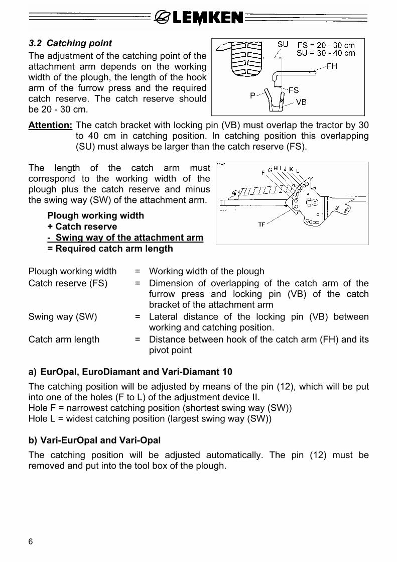
3.1 Working position (guiding point) The furrow press can be guided at four different distances to the plough. Therefore the pin (11) of the adjustment device (I) can be put into one of the holes with the holes A to D. That working position has to be chosen, where the furrow press is as close to the plough as possible, but does not touch the plough. Hole A = narrowest distance between plough and furrow press Hole B = approx. 20 cm larger distance than with hole A Hole C = approx. 40 cm larger distance than with hole A Hole D = largest distance between plough and furrow press, approx. 60 cm larger
than with hole A
6
3.2 Catching point The adjustment of the catching point of the attachment arm depends on the working width of the plough, the length of the hook arm of the furrow press and the required catch reserve. The catch reserve should be 20 - 30 cm.
Attention: The catch bracket with locking pin (VB) must overlap the tractor by 30 to 40 cm in catching position. In catching position this overlapping (SU) must always be larger than the catch reserve (FS).
The length of the catch arm must correspond to the working width of the plough plus the catch reserve and minus the swing way (SW) of the attachment arm.
Plough working width + Catch reserve - Swing way of the attachment arm = Required catch arm length
Plough working width = Working width of the plough Catch reserve (FS) = Dimension of overlapping of the catch arm of the
furrow press and locking pin (VB) of the catch bracket of the attachment arm
Swing way (SW) = Lateral distance of the locking pin (VB) between working and catching position.
Catch arm length = Distance between hook of the catch arm (FH) and its pivot point
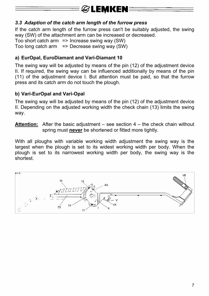
a) EurOpal, EuroDiamant and Vari-Diamant 10 The catching position will be adjusted by means of the pin (12), which will be put into one of the holes (F to L) of the adjustment device II. Hole F = narrowest catching position (shortest swing way (SW)) Hole L = widest catching position (largest swing way (SW)) b) Vari-EurOpal and Vari-Opal The catching position will be adjusted automatically. The pin (12) must be removed and put into the tool box of the plough.
7
3.3 Adaption of the catch arm length of the furrow press If the catch arm length of the furrow press can't be suitably adjusted, the swing way (SW) of the attachment arm can be increased or decreased. Too short catch arm => Increase swing way (SW) Too long catch arm => Decrease swing way (SW) a) EurOpal, EuroDiamant and Vari-Diamant 10 The swing way will be adjusted by means of the pin (12) of the adjustment device II. If required, the swing way can be influenced additionally by means of the pin (11) of the adjustment device I. But attention must be paid, so that the furrow press and its catch arm do not touch the plough. b) Vari-EurOpal and Vari-Opal The swing way will be adjusted by means of the pin (12) of the adjustment device II. Depending on the adjusted working width the check chain (13) limits the swing way. Attention: After the basic adjustment – see section 4 – the check chain without
spring must never be shortened or fitted more tightly. With all ploughs with variable working width adjustment the swing way is the largest when the plough is set to its widest working width per body. When the plough is set to its narrowest working width per body, the swing way is the shortest.
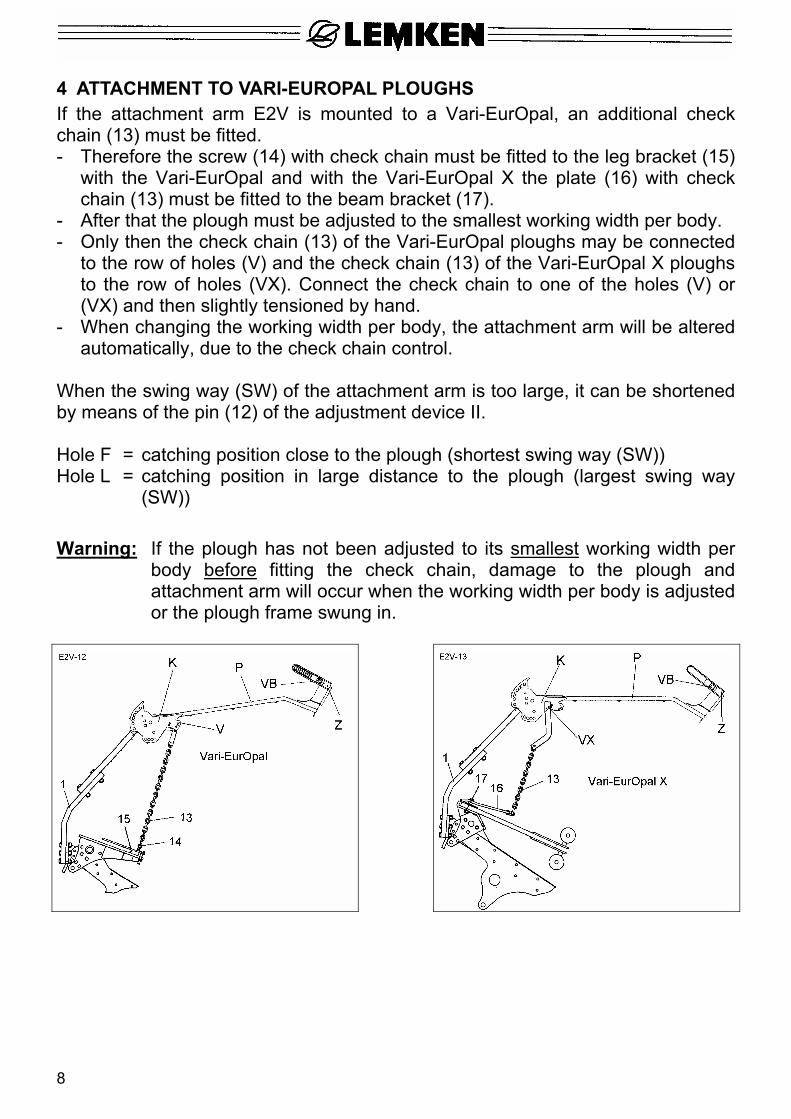
4 ATTACHMENT TO VARI-EUROPAL PLOUGHS If the attachment arm E2V is mounted to a Vari-EurOpal, an additional check chain (13) must be fitted. - Therefore the screw (14) with check chain must be fitted to the leg bracket (15)
with the Vari-EurOpal and with the Vari-EurOpal X the plate (16) with check chain (13) must be fitted to the beam bracket (17).
- After that the plough must be adjusted to the smallest working width per body. - Only then the check chain (13) of the Vari-EurOpal ploughs may be connected
to the row of holes (V) and the check chain (13) of the Vari-EurOpal X ploughs to the row of holes (VX). Connect the check chain to one of the holes (V) or (VX) and then slightly tensioned by hand.
- When changing the working width per body, the attachment arm will be altered automatically, due to the check chain control.
When the swing way (SW) of the attachment arm is too large, it can be shortened by means of the pin (12) of the adjustment device II. Hole F = catching position close to the plough (shortest swing way (SW)) Hole L = catching position in large distance to the plough (largest swing way
(SW)) Warning: If the plough has not been adjusted to its smallest working width per
body before fitting the check chain, damage to the plough and attachment arm will occur when the working width per body is adjusted or the plough frame swung in.
8
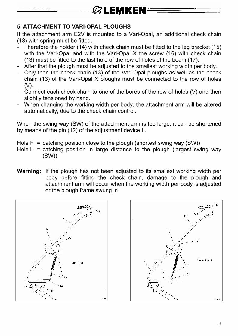
5 ATTACHMENT TO VARI-OPAL PLOUGHS If the attachment arm E2V is mounted to a Vari-Opal, an additional check chain (13) with spring must be fitted. - Therefore the holder (14) with check chain must be fitted to the leg bracket (15)
with the Vari-Opal and with the Vari-Opal X the screw (16) with check chain (13) must be fitted to the last hole of the row of holes of the beam (17).
- After that the plough must be adjusted to the smallest working width per body. - Only then the check chain (13) of the Vari-Opal ploughs as well as the check
chain (13) of the Vari-Opal X ploughs must be connected to the row of holes (V).
- Connect each check chain to one of the bores of the row of holes (V) and then slightly tensioned by hand.
- When changing the working width per body, the attachment arm will be altered automatically, due to the check chain control.
When the swing way (SW) of the attachment arm is too large, it can be shortened by means of the pin (12) of the adjustment device II. Hole F = catching position close to the plough (shortest swing way (SW)) Hole L = catching position in large distance to the plough (largest swing way
(SW)) Warning: If the plough has not been adjusted to its smallest working width per
body before fitting the check chain, damage to the plough and attachment arm will occur when the working width per body is adjusted or the plough frame swung in.
9
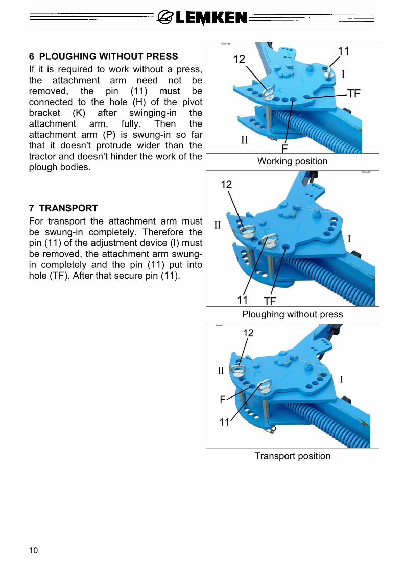
Working position
Ploughing without press
6 PLOUGHING WITHOUT PRESS If it is required to work without a press, the attachment arm need not be removed, the pin (11) must be connected to the hole (H) of the pivot bracket (K) after swinging-in the attachment arm, fully. Then the attachment arm (P) is swung-in so far that it doesn't protrude wider than the tractor and doesn't hinder the work of the plough bodies.
7 TRANSPORT For transport the attachment arm must be swung-in completely. Therefore the pin (11) of the adjustment device (I) must be removed, the attachment arm swung-in completely and the pin (11) put into hole (TF). After that secure pin (11).
Transport position
10
8 FAULT, REASON, REMEDY
Fault: The attachment arm doesn't swing-out far enough, the press won't be caught.
Reason: The swing way (SW) of the attachment arm isn't adjusted sufficiently or the catch arm of the press is too short.
Remedy: Adjust catch arm longer or increase the swing way of the attachment arm.
Fault: The attachment arm hits the press. Reason: The swing way (SW) of the attachment arm is adjusted too large or the
catch arm of the press is too short so that it does not protrude wide enough outside the press.
Remedy: The swing way of the attachment arm must be reduced. The catch arm protrusion outside the press must be increased. The protrusion must be at least 5 - 10 cm larger than the catch reserve.
Fault: The catch arm reach the furrow area and can be run over by the tractor. Reason: The catch arms are adjusted too long and the swing way of the arm too
short. Remedy: Adjust length of catch arm shorter and increase the swing way of the
attachment arm. In connection with the Lemken Variopack the distance between the press and the plough will be increased by means of re-hanging the guiding chain of the catch arm of the press or by removing some rings from the press and refitting them to the opposite side of the press.
11
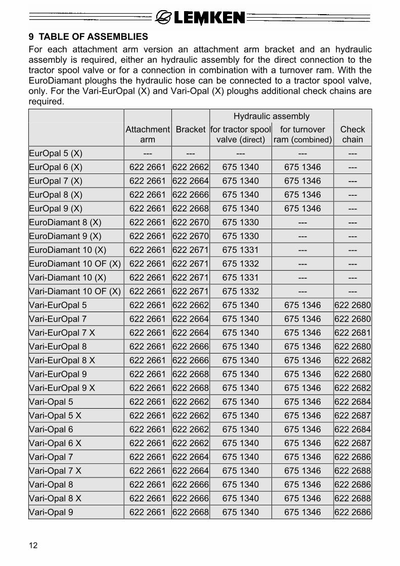
9 TABLE OF ASSEMBLIES For each attachment arm version an attachment arm bracket and an hydraulic assembly is required, either an hydraulic assembly for the direct connection to the tractor spool valve or for a connection in combination with a turnover ram. With the EuroDiamant ploughs the hydraulic hose can be connected to a tractor spool valve, only. For the Vari-EurOpal (X) and Vari-Opal (X) ploughs additional check chains are required.
Hydraulic assembly Attachment
arm Bracket for tractor spool
valve (direct) for turnover
ram (combined)Check chain
EurOpal 5 (X) --- --- --- --- --- EurOpal 6 (X) 622 2661 622 2662 675 1340 675 1346 --- EurOpal 7 (X) 622 2661 622 2664 675 1340 675 1346 --- EurOpal 8 (X) 622 2661 622 2666 675 1340 675 1346 --- EurOpal 9 (X) 622 2661 622 2668 675 1340 675 1346 --- EuroDiamant 8 (X) 622 2661 622 2670 675 1330 --- --- EuroDiamant 9 (X) 622 2661 622 2670 675 1330 --- --- EuroDiamant 10 (X) 622 2661 622 2671 675 1331 --- --- EuroDiamant 10 OF (X) 622 2661 622 2671 675 1332 --- --- Vari-Diamant 10 (X) 622 2661 622 2671 675 1331 --- --- Vari-Diamant 10 OF (X) 622 2661 622 2671 675 1332 --- --- Vari-EurOpal 5 622 2661 622 2662 675 1340 675 1346 622 2680Vari-EurOpal 7 622 2661 622 2664 675 1340 675 1346 622 2680Vari-EurOpal 7 X 622 2661 622 2664 675 1340 675 1346 622 2681Vari-EurOpal 8 622 2661 622 2666 675 1340 675 1346 622 2680Vari-EurOpal 8 X 622 2661 622 2666 675 1340 675 1346 622 2682Vari-EurOpal 9 622 2661 622 2668 675 1340 675 1346 622 2680Vari-EurOpal 9 X 622 2661 622 2668 675 1340 675 1346 622 2682Vari-Opal 5 622 2661 622 2662 675 1340 675 1346 622 2684Vari-Opal 5 X 622 2661 622 2662 675 1340 675 1346 622 2687Vari-Opal 6 622 2661 622 2662 675 1340 675 1346 622 2684Vari-Opal 6 X 622 2661 622 2662 675 1340 675 1346 622 2687Vari-Opal 7 622 2661 622 2664 675 1340 675 1346 622 2686Vari-Opal 7 X 622 2661 622 2664 675 1340 675 1346 622 2688Vari-Opal 8 622 2661 622 2666 675 1340 675 1346 622 2686Vari-Opal 8 X 622 2661 622 2666 675 1340 675 1346 622 2688Vari-Opal 9 622 2661 622 2668 675 1340 675 1346 622 2686
12
13
Vari-Opal 9 X 622 2661 622 2668 675 1340 675 1346 622 2688
10 SAFETY INSTRUCTIONS • Read and adhere to the Safety Instructions of the corresponding
Lemken plough! • The attachment arm swings into the catch position by means of
spring force. Pay attention to a sufficient safety distance! • In the area of the pivot bracket (K) and the spring rod are pinch
points!
• The spring (10) is under high spring tension! • The pins (11) and (12) must always be secured by means of the supplied
securing pins! • The stop screw (AS) must always be fitted; this screw prevents a turning of the
attachment arm to the front!