Embed Size (px)
Citation preview
Betriebsanleitung Programmierbare Multi-Messumformer SINEAX DME 424/442
Mode d’emploi Convertisseurs de mesure multiples programmables SINEAX DME 424/442
Operating Instructions Programmable multi-transducers SINEAX DME 424/442
DME 424/442-1 B d-f-e 122 250-06 07.15
Camille Bauer Metrawatt AG
Aargauerstrasse 7
CH-5610 Wohlen
Phone +41 56 618 21 11
Fax +41 56 618 21 21
www.camillebauer.com
3
Sicherheitshinweise, die unbedingt beachtet werden
müssen, sind in dieser Betriebsanleitung mit folgenden
Symbolen markiert:
Les conseils de sécurité qui doivent impérativement
être observés sont marqués des symboles ci-contre
dans le présent mode d’emploi:
The following symbols in the Operating Instructions
indicate safety precautions which must be strictly
observed:
Betriebsanleitung Programmierbare Multi-MessumformerSINEAX DME 424/442 ....................................Seite 4
Mode d’emploi Convertisseurs de mesure multiplesprogrammables SINEAX DME 424/442 ................................. Page 14
Operating Instructions Programmable multi-transducers SINEAX DME 424/442 ................................. Page 25
Geräte dürfen nur fachgerecht entsorgt werden!
Les appareils ne peuvent être éliminés que de façon appropriée!
The instruments must only be disposed of in the correct way!

4
Betriebsanleitung
Programmierbare Multi-Messumformer SINEAX DME 424/442
1. Erst lesen, dann …
Der einwandfreie und gefahrlose Betrieb
setzt voraus, dass die Betriebsanleitung
gelesen und die in den Abschnitten
4. Mechanischer Einbau
5. Elektrische Anschlüsse
6. Inbetriebnahme
11. Sicherheitshinweise
enthaltenen Sicherheitshinweise beachtet werden.
Der Umgang mit diesem Gerät sollte nur durch ent-
sprechend geschultes Personal erfolgen, das das
Gerät kennt und berechtigt ist, Arbeiten in elektrischen
An lagen auszuführen.
Bei einem Eingriff in das Gerät erlischt der Garantie-
anspruch!
2. Lieferumfang (Bilder 1, 2 und 3)
Inhaltsverzeichnis
1. Erst lesen, dann... ........................................................ 4
2. Lieferumfang ................................................................4
3. Kurzbeschreibung ........................................................4
4. Mechanischer Einbau ...................................................4
4.1 Montage auf Hutschiene.........................................4
4.2 Befestigung auf einer Montagefl äche .....................5
5. Elektrische Anschlüsse .................................................5
6. Inbetriebnahme ............................................................8
6.1 Technische Kenndaten ...........................................9
6.2 Programmierung des Messumformers .................11
6.3 Betrieb der Digitalausgänge .................................12
7. Änderung der Analogausgänge ..................................12
7.1 Ohne Hardware-Anpassung .................................12
8. Wartungshinweise .......................................................13
9. Demontage-Hinweis ...................................................13
10. Mass-Skizzen .............................................................13
11. Sicherheitshinweise ....................................................13
12. Konformitätsbescheinigung ........................................36
Bild 1 Bild 2
3. Kurzbeschreibung
Die Multi-Messumformer der Reihe SINEAX DME 4 erfassen
gleichzeitig mehrere Grössen eines elektrischen Netzes und
verarbeiten sie zu 2 bzw. 4 analogen Ausgangsgrössen.
2 bzw. 4 Digitalausgänge sind zur Grenzwert-Überwachung
oder Energie-Zählung einsetzbar. 2 Grenzwertausgänge
lassen die Programmierung einer logischen Verknüpfung
von bis zu je 3 Messgrössen zu.
Die RS 232-Schnittstelle an den Multi-Messumformern dient
dazu, mittels PC und Software sowohl die Programmierung
vornehmen als auch interessante Zusatzfunktionen abrufen
zu können.
Programmieren lassen sich, um die wichtigsten Parameter
zu nennen: alle üblichen Anschlussarten, die Messgrössen,
die Bemessungswerte der Eingangsgrössen, das Übertra-
gungsverhalten für jede Ausgangsgrösse usw.
Zu den Zusatzfunktionen zählen u.a.: der Netz-System-
Check, die Anzeige der Messwerte auf dem Monitor des
PCs, die Simulation der Ausgänge sowie der Druck von
Typenschildern.
4. Mechanischer Einbau
Die Befestigung des Messumformers erfolgt wahlweise auf
einer Hutschiene oder direkt an einer Wand bzw. auf einer
Montagefl äche.
Bei der Bestimmung des Montageortes müs-
sen die «Umgebungsbedingungen», Abschnitt
«6.1 Technische Kenndaten», eingehalten wer-
den!
4.1 Montage auf Hutschiene
Gehäuse auf Hutschiene (EN 50 022) aufschnappen (siehe
Bild 4).
Bild 4. Montage auf Hutschiene 35 × 15 oder 35 × 7,5 mm.
Camille Bauer AG
Aargauerstrasse 7
CH-5610 Wohlen/Switzerland
Phone +41 56 618 21 11
Fax +41 56 618 24 58
e-Mail: [email protected]
http://www.camillebauer.com
DME 424/442 B d-f-e 122 250 03.08
BetriebsanleitungProgrammierbare Multi-MessumformerSINEAX DME 424/442
Mode d’emploiConvertisseurs de mesure multiplesprogrammables SINEAX DME 424/442
Operating InstructionsProgrammable multi-transducersSINEAX DME 424/442
Messumformer (Bild 1)
1 Betriebsanleitung (Bild 2), dreisprachig: Deutsch,
Französisch, Englisch
1 leeres Typenschild (Bild 3), zum Eintragen der program-
mierten Daten
Bild 3
15+ 16–A 17+ 18–B
19+ 20–E 21+ 22–F
23+ 24–G 25+ 26–H
5
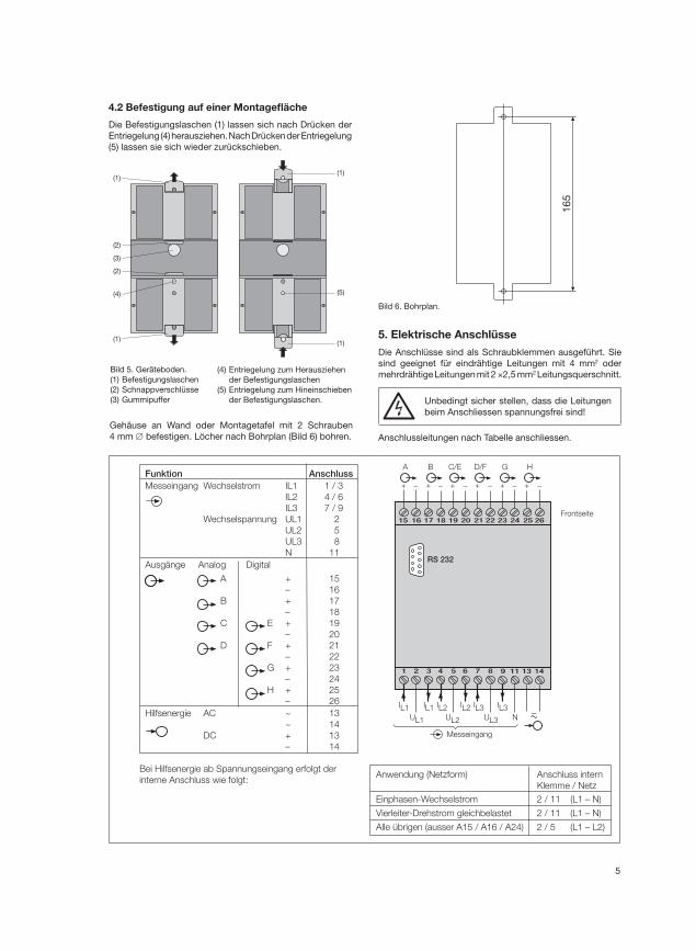
Funktion AnschlussMesseingang Wechselstrom IL1 1 / 3
IL2 4 / 6
IL3 7 / 9
Wechselspannung UL1 2
UL2 5
UL3 8
N 11
Ausgänge Analog Digital
A + 15
– 16
B + 17
– 18
C E + 19
– 20
D F + 21
– 22
G + 23
– 24
H + 25
– 26
Hilfsenergie AC ~ 13
~ 14
DC + 13
– 14
Bei Hilfsenergie ab Spannungseingang erfolgt der
interne Anschluss wie folgt:Anwendung (Netzform) Anschluss intern
Klemme / Netz
Einphasen-Wechselstrom 2 / 11 (L1 – N)
Vierleiter-Drehstrom gleichbelastet 2 / 11 (L1 – N)
Alle übrigen (ausser A15 / A16 / A24) 2 / 5 (L1 – L2)
2221201918171615
87654321
26252423
1413119
–
–+ + + + + +– – – –
A
–
B C/E D/F G H
UL2UL1 UL3
IL1 IL2 IL3N
RS 232
Frontseite
IL1 IL2 IL3
Messeingang
4.2 Befestigung auf einer Montagefl äche
Die Befestigungslaschen (1) lassen sich nach Drücken der
Entriegelung (4) herausziehen. Nach Drücken der Entriegelung
(5) lassen sie sich wieder zurückschieben.
Bild 5. Geräteboden.
(1) Befestigungslaschen
(2) Schnappverschlüsse
(3) Gummipuffer
(4) Entriegelung zum Herausziehen
der Befestigungslaschen
(5) Entriegelung zum Hineinschieben
der Befestigungslaschen.
Gehäuse an Wand oder Montagetafel mit 2 Schrauben
4 mm ∅ befestigen. Löcher nach Bohrplan (Bild 6) bohren.
Bild 6. Bohrplan.
5. Elektrische Anschlüsse
Die Anschlüsse sind als Schraubklemmen ausgeführt. Sie
sind geeignet für eindrähtige Leitungen mit 4 mm2 oder
mehrdrähtige Leitungen mit 2 ×2,5 mm2 Leitungsquerschnitt.
Unbedingt sicher stellen, dass die Leitungen
beim Anschliessen spannungsfrei sind!
Anschlussleitungen nach Tabelle anschliessen.
(1)
(2)
(3)
(2)
(4)
(1)
(1)
(1)
(5)
16
5
6
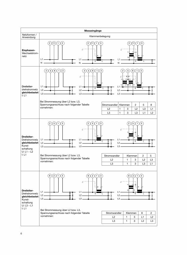
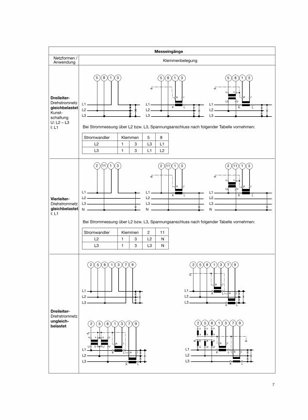
Messeingänge
Netzformen / Anwendung Klemmenbelegung
L1
N
11 312
Einphasen-
Wechselstrom-
netz
L1
5 31
L1
k l
K L
2 5 31
L1
v
V
u
Uk l
K L
2 5 312
L2
L3
L2
L3
L2
L3
Dreileiter-
Drehstromnetz
gleichbelastet
Kunst-
schaltung
U: L1 – L2
I: L1
L1
L2
L3
5 182 3
L1
L2
L3
k l
K L
5 182 3
L1
L2
L3
u
U
v
V
v
V
u
Uk l
K L
5 182 3
Dreileiter-drehstromnetz
gleichbelastet
I: L1
Bei Strommessung über L2 bzw. L3,
Spannungsanschluss nach folgender Tabelle
vornehmen:
Bei Strommessung über L2 bzw. L3,
Spannungsanschluss nach folgender Tabelle
vornehmen:
L1
N
k l
K L
2 11 31
L1
N
v
V
u
Uk l
K L
2 11 31
L1
2 31
L1
k l
K L
8 2 31
L1
v
V
u
U
k l
K L
8 2 318
L2
L3
L2
L3
L2
L3
Dreileiter-
Drehstromnetz
gleichbelastet
Kunst-
schaltung
U: L3 – L1
I: L1Bei Strommessung über L2 bzw. L3,
Spannungsanschluss nach folgender Tabelle
vornehmen:
Stromwandler Klemmen 2 5 8
L2 1 3 L2 L3 L1
L3 1 3 L3 L1 L2
Stromwandler Klemmen 2 5
L2 1 3 L2 L3
L3 1 3 L3 L1
Stromwandler Klemmen 8 2
L2 1 3 L1 L2
L3 1 3 L2 L3
7
Messeingänge
Netzformen / Anwendung Klemmenbelegung
Dreileiter-
Drehstromnetz
ungleich-
belastet
L1
L2
L3
5 182 3 7 9
L1
L2
L3
k l
K L k l
K L
5 182 3 7 9
L1
L2
L3
u
U
v
V
v
V
u
Uk l
K L k l
K L
5 182 3 7 9
L1
L2
L3
k l
K L k l
K L
xxx
uuu
XXX
UU U
5 182 3 7 9
L1
N
11 31
L1
N
k l
K L
2 11 31
L1
v
V
u
Uk l
K L
2 11 312
L2
L3
L2
L3
N
L2
L3
Vierleiter-
Drehstromnetz
gleichbelastet
I: L1
L1
8 31
L1
k l
K L
5 8 31
L1
v
V
u
U
k l
K L
5 8 315
L2
L3
L2
L3
L2
L3
Dreileiter-
Drehstromnetz
gleichbelastet
Kunst-
schaltung
U: L2 – L3
I: L1 Bei Strommessung über L2 bzw. L3, Spannungsanschluss nach folgender Tabelle vornehmen:
Stromwandler Klemmen 5 8
L2 1 3 L3 L1
L3 1 3 L1 L2
Bei Strommessung über L2 bzw. L3, Spannungsanschluss nach folgender Tabelle vornehmen:
Stromwandler Klemmen 2 11
L2 1 3 L2 N
L3 1 3 L3 N
8
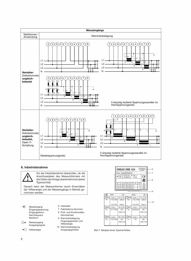
Messeingänge
Netzformen / Anwendung Klemmenbelegung
Vierleiter-
Drehstromnetz
ungleich-
belastet
Vierleiter-
Drehstromnetz
ungleich-
belastet,
Open-Y-
Schaltung
3 einpolig isolierte Spannungswandler imHochspannungsnetz
Niederspannungsnetz2 einpolig isolierte Spannungswandler im Hochspannungsnetz
L1
L2
L3
k l
K L
k l
K L
k l
K L
N
xxx
uuu
XXX
UU U
5 1182 1 3 4 6 7 9
L1
L2
L3
N
5 1182 1 3 4 6 7 9
L1
L2
L3
k l
K L
k l
K L
k l
K L
N
5 1182 1 3 4 6 7 9
L1
L2
L3
k l
K L
k l
K L
k l
K L
N
82 1 3 4 6 7 911
L1
L2
L3
kl
K
k l
K L
k l
K L
xx
uu
X
U
2 431 5 6 7 8 9 11
X
U
L
N
Bild 7. Beispiel eines Typenschildes.
| 0.25* c | | 0.25* c |
| 0.25 c | | 0.25 c |
| 0.25 c | | 0.25 c |
P1 –115.47W
115.47W
–20mA
20mA
15+ 16–A
100V 2A 50Hz 3N~
P2 –115.47W
115.47W
–20mA
20mA
17+ 18–B
19+ 20–E 21+ 22–FP> 311.77kW ON Q> 34.64kvar ON
Ydel=min Ydel=min
23+ 24–G 25+ 26–H
P1> 115.47kW ON I1> 2A ON
Ydel=min Ydel=min
6
7
8
9
10
SINEAX DME 424Camille Bauer AGCH - 5610 Wohlen
Switzerland
Ord: 123/45679/007/1
AC/DC 85-230 V50/60 Hz 10 VA
IL1
IL2
IL3
1
4
7
3
6
9
UL1
UL2
UL3
2
5
8
N 11
13
14
6. Inbetriebnahme
Vor der Inbetriebnahme überprüfen, ob die
Anschlussdaten des Messumformers mit
den Daten der Anlage übereinstimmen (siehe
Typenschild).
Danach kann der Messumformer durch Einschalten
der Hilfsenergie und der Messeingänge in Betrieb ge-
nommen werden.
Messeingang
Eingangsspannung
Eingangsstrom
Nennfrequenz
Netzform
Messausgang
Ausgangssignal
Hilfsenergie
6 Hersteller
7 Fabrikations-Nummer
8 Prüf- und Konformitäts-
Kennzeichen
9 Klemmenbelegung
Eingangsgrössen und
Hilfsenergie
10 Klemmenbelegung
Ausgangsgrössen
9
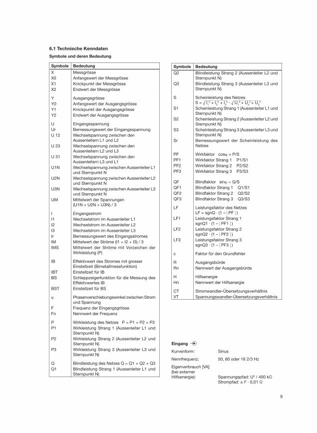
6.1 Technische Kenndaten
Symbole und deren Bedeutung
Symbole Bedeutung
X Messgrösse
X0 Anfangswert der Messgrösse
X1 Knickpunkt der Messgrösse
X2 Endwert der Messgrösse
Y Ausgangsgrösse
Y0 Anfangswert der Ausgangsgrösse
Y1 Knickpunkt der Ausgangsgrösse
Y2 Endwert der Ausgangsgrösse
U Eingangsspannung
Ur Bemessungswert der Eingangsspannung
U 12 Wechselspannung zwischen den
Aussenleitern L1 und L2
U 23 Wechselspannung zwischen den
Aussenleitern L2 und L3
U 31 Wechselspannung zwischen den
Aussenleitern L3 und L1
U1N Wechselspannung zwischen Aussenleiter L1
und Sternpunkt N
U2N Wechselspannung zwischen Aussenleiter L2
und Sternpunkt N
U3N Wechselspannung zwischen Aussenleiter L3
und Sternpunkt N
UM Mittelwert der Spannungen
(U1N + U2N + U3N) / 3
I Eingangsstrom
I1 Wechselstrom im Aussenleiter L1
I2 Wechselstrom im Aussenleiter L2
I3 Wechselstrom im Aussenleiter L3
Ir Bemessungswert des Eingangsstromes
IM Mittelwert der Ströme (I1 + I2 + I3) / 3
IMS Mittelwert der Ströme mit Vorzeichen der
Wirk leistung (P)
IB Effektivwert des Stromes mit grosser
Einstellzeit (Bimetallmessfunktion)
IBT Einstellzeit für IB
BS Schleppzeigerfunktion für die Messung des
Effektivwertes IB
BST Einstellzeit für BS
ϕ Phasenverschiebungswinkel zwischen Strom
und Spannung
F Frequenz der Eingangsgrösse
Fn Nennwert der Frequenz
P Wirkleistung des Netzes P = P1 + P2 + P3
P1 Wirkleistung Strang 1 (Aussenleiter L1 und
Sternpunkt N)
P2 Wirkleistung Strang 2 (Aussenleiter L2 und
Sternpunkt N)
P3 Wirkleistung Strang 3 (Aussenleiter L3 und
Sternpunkt N)
Q Blindleistung des Netzes Q = Q1 + Q2 + Q3
Q1 Blindleistung Strang 1 (Aussenleiter L1 und
Sternpunkt N)
Symbole Bedeutung
Q2 Blindleistung Strang 2 (Aussenleiter L2 und
Sternpunkt N)
Q3 Blindleistung Strang 3 (Aussenleiter L3 und
Sternpunkt N)
S Scheinleistung des Netzes
S = √ I12 + I
22 + I
32 · √ U
12 + U
22 + U
32
S1 Scheinleistung Strang 1 (Aussenleiter L1 und
Sternpunkt N)
S2 Scheinleistung Strang 2 (Aussenleiter L2 und
Sternpunkt N)
S3 Scheinleistung Strang 3 (Aussenleiter L3 und
Sternpunkt N)
Sr Bemessungswert der Scheinleistung des
Netzes
PF Wirkfaktor cosϕ = P/S
PF1 Wirkfaktor Strang 1 P1/S1
PF2 Wirkfaktor Strang 2 P2/S2
PF3 Wirkfaktor Strang 3 P3/S3
QF Blindfaktor sinϕ = Q/S
QF1 Blindfaktor Strang 1 Q1/S1
QF2 Blindfaktor Strang 2 Q2/S2
QF3 Blindfaktor Strang 3 Q3/S3
LF Leistungsfaktor des Netzes
LF = sgnQ · (1 – | PF | )LF1 Leistungsfaktor Strang 1
sgnQ1 · (1 – | PF1 | )LF2 Leistungsfaktor Strang 2
sgnQ2 · (1 – | PF2 | )LF3 Leistungsfaktor Strang 3
sgnQ3 · (1 – | PF3 | )
c Faktor für den Grundfehler
R Ausgangsbürde
Rn Nennwert der Ausgangsbürde
H Hilfsenergie
Hn Nennwert der Hilfsenergie
CT Stromwandler-Übersetzungsverhältnis
VT Spannungswandler-Übersetzungsverhältnis
Eingang
Kurvenform: Sinus
Nennfrequenz: 50, 60 oder 16 2/3 Hz
Eigenverbrauch [VA]
(bei externer
Hilfsenergie): Spannungspfad: U2 / 400 kΩ
Strompfad: ≤ I2 · 0,01 Ω
10
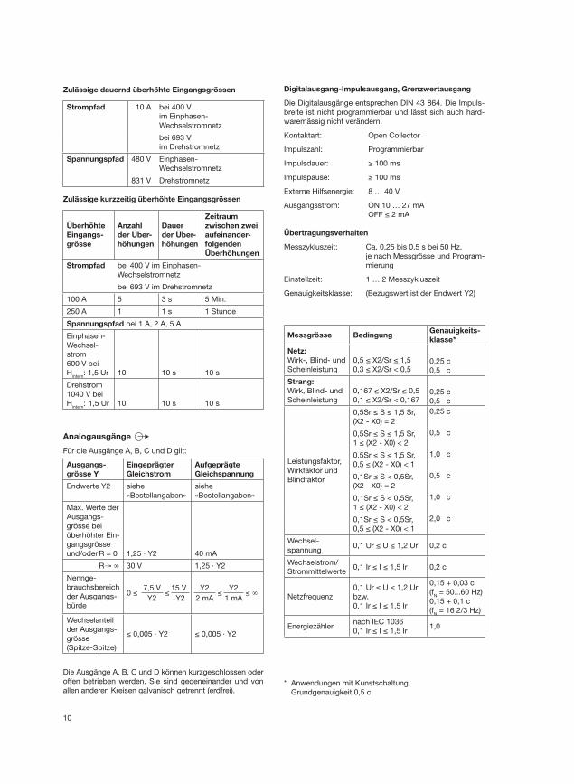
Zulässige dauernd überhöhte Eingangsgrössen
Strompfad 10 A bei 400 V
im Einphasen-
Wechselstromnetz
bei 693 V
im Drehstromnetz
Spannungspfad 480 V Einphasen-
Wechselstromnetz
831 V Drehstromnetz
Zulässige kurzzeitig überhöhte Eingangsgrössen
Überhöhte
Eingangs-
grösse
Anzahl
der Über-
höhungen
Dauer
der Über-
höhungen
Zeitraum
zwischen zwei
aufeinander-
folgenden
Überhöhungen
Strompfad bei 400 V im Einphasen-
Wechselstromnetz
bei 693 V im Drehstromnetz
100 A 5 3 s 5 Min.
250 A 1 1 s 1 Stunde
Spannungspfad bei 1 A, 2 A, 5 A
Einphasen-
Wechsel-
strom
600 V bei
Hintern
: 1,5 Ur 10 10 s 10 s
Drehstrom
1040 V bei
Hintern
: 1,5 Ur 10 10 s 10 s
Analogausgänge
Für die Ausgänge A, B, C und D gilt:
Ausgangs-
grösse Y
Eingeprägter
Gleichstrom
Aufgeprägte
Gleichspannung
Endwerte Y2 siehe
«Bestellangaben»
siehe
«Bestellangaben»
Max. Werte der
Ausgangs-
grösse bei
überhöhter Ein-
gangsgrösse
und/oder R = 0 1,25 · Y2 40 mA
R→ ∞ 30 V 1,25 · Y2
Nennge-
brauchsbereich
der Ausgangs-
bürde
0 ≤7,5 V
≤15 V
Y2 Y2
Y2 ≤
Y2 ≤ ∞
2 mA 1 mA
Wechselanteil
der Ausgangs-
grösse
(Spitze-Spitze)
≤ 0,005 · Y2 ≤ 0,005 · Y2
Die Ausgänge A, B, C und D können kurzgeschlossen oder
offen betrieben werden. Sie sind gegeneinander und von
allen anderen Kreisen galvanisch getrennt (erdfrei).
Digitalausgang-Impulsausgang, Grenzwertausgang
Die Digitalausgänge entsprechen DIN 43 864. Die Impuls-
breite ist nicht programmierbar und lässt sich auch hard-
waremässig nicht verändern.
Kontaktart: Open Collector
Impulszahl: Programmierbar
Impulsdauer: ≥ 100 ms
Impulspause: ≥ 100 ms
Externe Hilfsenergie: 8 … 40 V
Ausgangsstrom: ON 10 … 27 mA
OFF ≤ 2 mA
Übertragungsverhalten
Messzykluszeit: Ca. 0,25 bis 0,5 s bei 50 Hz,
je nach Messgrösse und Program-
mierung
Einstellzeit: 1 … 2 Messzykluszeit
Genauigkeitsklasse: (Bezugswert ist der Endwert Y2)
Messgrösse BedingungGenauigkeits-
klasse*
Netz:
Wirk-, Blind- und
Scheinleistung
0,5 ≤ X2/Sr ≤ 1,5
0,3 ≤ X2/Sr < 0,50,25 c
0,5 c
Strang:
Wirk, Blind- und
Scheinleistung
0,167 ≤ X2/Sr ≤ 0,5
0,1 ≤ X2/Sr < 0,1670,25 c
0,5 c
Leistungsfaktor,
Wirkfaktor und
Blindfaktor
0,5Sr ≤ S ≤ 1,5 Sr,
(X2 - X0) = 2
0,25 c
0,5Sr ≤ S ≤ 1,5 Sr,
1 ≤ (X2 - X0) < 2
0,5 c
0,5Sr ≤ S ≤ 1,5 Sr,
0,5 ≤ (X2 - X0) < 1
1,0 c
0,1Sr ≤ S < 0,5Sr,
(X2 - X0) = 2
0,5 c
0,1Sr ≤ S < 0,5Sr,
1 ≤ (X2 - X0) < 2
1,0 c
0,1Sr ≤ S < 0,5Sr,
0,5 ≤ (X2 - X0) < 1
2,0 c
Wechsel-
spannung0,1 Ur ≤ U ≤ 1,2 Ur 0,2 c
Wechselstrom/
Strommittelwerte0,1 Ir ≤ I ≤ 1,5 Ir 0,2 c
Netzfrequenz
0,1 Ur ≤ U ≤ 1,2 Ur
bzw.
0,1 Ir ≤ I ≤ 1,5 Ir
0,15 + 0,03 c
(fN = 50...60 Hz)
0,15 + 0,1 c
(fN = 16 2/3 Hz)
Energiezählernach IEC 1036
0,1 Ir ≤ I ≤ 1,5 Ir1,0
* Anwendungen mit Kunstschaltung
Grundgenauigkeit 0,5 c
11
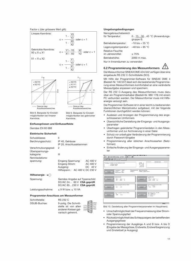
Factor c (der grössere Wert gilt):
Lineare Kennlinie:
c =
1 -Y0
oder c = 1Y2
1 -X0
X2
Geknickte Kennlinie:
X0 ≤ X ≤ X1 c =Y1 - Y0
·X2
oder c = 1X1 - X0 Y2
X1 < X ≤ X2
c =
1 -Y1
oder c = 1Y2
1 -X1
X2
Y
X
Grenze desAussteuerbereiches
X0/Y0
X2/Y2
Y
X
Grenze desAussteuerbereiches
X0/Y0
X2/Y2
X1/Y1
Bild 9. Beispiele für Einstell-
möglichkeiten bei geknickter
Kennlinie.
Bild 8. Beispiele für Einstell-
möglichkeiten bei linearer
Kennlinie.
Einfl ussgrössen und Einfl usseffekte
Gemäss EN 60 688
Elektrische Sicherheit
Schutzklasse: II
Berührungsschutz: IP 40, Gehäuse
IP 20, Anschlussklemmen
Verschmutzungsgrad: 2
Überspannungs-
kategorie: III
Nennisolations-
spannung: Eingang Spannung: AC 400 V
Eingang Strom: AC 400 V
Ausgang: DC 40 V
Hilfsspann.: AC 400 V, DC 230 V
Hilfsenergie
Spannung: Gemäss Angabe auf Typenschild
DC/AC 24… 60 V CSA geprüft
DC/AC 85…230 V CSA geprüft
Leistungsaufnahme: ≤ 9 W bzw. ≤ 10 VA
Programmier-Anschluss am Messumformer
Schnittstelle: RS 232 C
DSUB-Buchse: 9-polig. Die Schnitt-
stelle ist von allen
anderen Kreisen gal-
vanisch getrennt.
95
6 1
CTSRTSDSR
GNDDTRTXDRXD
Umgebungsbedingungen
Nenngebrauchsbereich
für Temperatur: 0…15…30…45 °C (Anwendungs-
gruppe II)
Betriebstemperatur: –10 bis + 55 °C
Lagerungstemperatur: –40 bis + 85 °C
Relative Feuchte
im Jahresmittel: ≤ 75%
Betriebshöhe: 2000 m max.
Nur in Innenräumen zu verwenden
6.2 Programmierung des Messumformers
Die Messumformer SINEAX DME 424/442 verfügen über eine
eingebaute RS 232 C-Schnittstelle (SCI).
Mit Hilfe der Programmier-Software für SINEAX DME 4
(Bestell-Nr. 146 557) lässt sich die bestehende Programmie-
rung eines Messumformers komfortabel an eine veränderte
Messaufgabe anpassen und speichern.
Der RS 232 C-Ausgang des Messumformers muss dazu
über ein Programmierkabel (Bestell-Nr. 980 179) mit einem
PC verbunden werden. Der Messumformer muss mit Hilfs-
energie versorgt sein.
Die Programmier-Software ist in einer leicht zu bedienenden
übersichtlichen Menüstruktur aufgebaut, mit der folgende
Funktionen durchgeführt werden können:
• Auslesen und Anzeigen der Programmierung des ange-
schlossenen Umformers
• Übersichtliche Darstellung der Eingangs- und Ausgangs-
parameter
• Übertragen geänderter Programmierdaten in den Mess-
umformer und zur Archivierung in einer Datei
• Schutz vor unbefugter Veränderung der Programmierung
durch Passwort-Eingabe
• Programmierung aller üblichen Anschlussarten (Netz-
formen)
• Einfache Änderung der Eingangs- und Ausgangsparame-
ter
Bild 10. Darstellung aller Programmierparameter im Hauptmenü.
• Umschaltmöglichkeit der Frequenzmessung über Strom-
oder Spannungspfad
• Rücksetzmöglichkeit des Schleppzeigers der betreffenden
Ausgangsgrösse
• Programmierung der Ausgänge A und B bzw. A bis D
(Eingabe der Messgrösse, Endwerte, Endwertbegrenzung
und Einstellzeit je Ausgang)
12
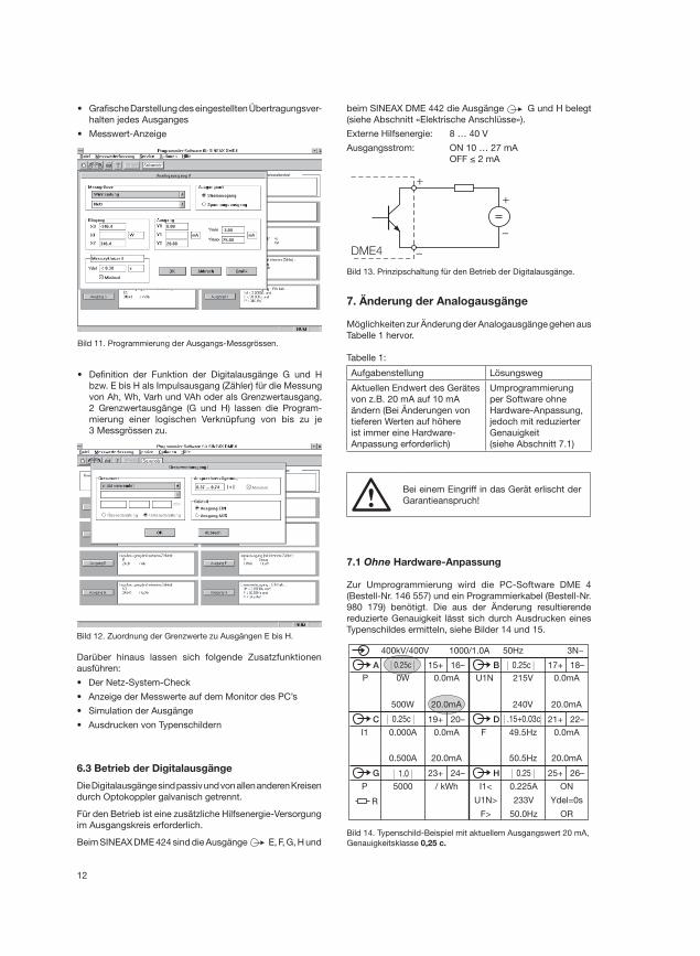
7. Änderung der Analogausgänge
Möglichkeiten zur Änderung der Analogausgänge gehen aus
Tabelle 1 hervor.
Tabelle 1:
Aufgabenstellung Lösungsweg
Aktuellen Endwert des Gerätes
von z.B. 20 mA auf 10 mA
ändern (Bei Änderungen von
tieferen Werten auf höhere
ist immer eine Hardware-
Anpassung erforderlich)
Umprogrammierung
per Software ohne
Hardware-Anpassung,
jedoch mit reduzierter
Genauigkeit
(siehe Abschnitt 7.1)
Bei einem Eingriff in das Gerät erlischt der
Garantieanspruch!
| 0.25c | | 0.25c |
| 0.25c | | .15+0.03c|
| 1.0 | | 0.25 |
P 0W
500W
0.0mA
20.0mA
15+ 16–A
400kV/400V 1000/1.0A 50Hz 3N~
U1N 215V
240V
0.0mA
20.0mA
17+ 18–B
19+ 20–C 21+ 22–DI1 0.000A 0.0mA F 49.5Hz 0.0mA
20.0mA
23+ 24–G 25+ 26–H
P 5000 / kWh I1<
U1N>
F>
0.500A 20.0mA 50.5Hz
0.225A
233V
50.0Hz
ON
Ydel=0s
OR
R
• Grafi sche Darstellung des eingestellten Übertragungsver-
halten jedes Ausganges
• Messwert-Anzeige
Bild 11. Programmierung der Ausgangs-Messgrössen.
• Defi nition der Funktion der Digitalausgänge G und H
bzw. E bis H als Impulsausgang (Zähler) für die Messung
von Ah, Wh, Varh und VAh oder als Grenzwertausgang,
2 Grenzwertausgänge (G und H) lassen die Program-
mierung einer logischen Verknüpfung von bis zu je
3 Messgrössen zu.
Bild 12. Zuordnung der Grenzwerte zu Ausgängen E bis H.
Darüber hinaus lassen sich folgende Zusatzfunktionen
ausführen:
• Der Netz-System-Check
• Anzeige der Messwerte auf dem Monitor des PC’s
• Simulation der Ausgänge
• Ausdrucken von Typenschildern
6.3 Betrieb der Digitalausgänge
Die Digitalausgänge sind passiv und von allen anderen Kreisen
durch Optokoppler galvanisch getrennt.
Für den Betrieb ist eine zusätzliche Hilfsenergie-Versorgung
im Ausgangskreis erforderlich.
Beim SINEAX DME 424 sind die Ausgänge E, F, G, H und
+
–DME4
–
+
Bild 13. Prinzipschaltung für den Betrieb der Digitalausgänge.
beim SINEAX DME 442 die Ausgänge G und H belegt
(siehe Abschnitt «Elektrische Anschlüsse»).
Externe Hilfsenergie: 8 … 40 V
Ausgangsstrom: ON 10 … 27 mA
OFF ≤ 2 mA
7.1 Ohne Hardware-Anpassung
Zur Umprogrammierung wird die PC-Software DME 4
(Bestell-Nr. 146 557) und ein Programmierkabel (Bestell-Nr.
980 179) benötigt. Die aus der Änderung resultierende
reduzierte Genauigkeit lässt sich durch Ausdrucken eines
Typenschildes ermitteln, siehe Bilder 14 und 15.
Bild 14. Typenschild-Beispiel mit aktuellem Ausgangswert 20 mA,
Genauigkeitsklasse 0,25 c.
13
| 0.45c | | 0.25c |
| 0.25c | | .15+0.03c |
| 1.0 | | 0.25 |
P 0W
500W
0.0mA
10.0mA
15+ 16–A
400kV/400V 1000/1.0A 50Hz 3N~
U1N 215V
240V
0.0mA
20.0mA
17+ 18–B
19+ 20–C 21+ 22–DI1 0.000A 0.0mA F 49.5Hz 0.0mA
20.0mA
23+ 24–G 25+ 26–H
P 5000 / kWh I1<
U1N>
F>
0.500A 20.0mA 50.5Hz
0.225A
233V
50.0Hz
ON
Ydel=0s
OR
R
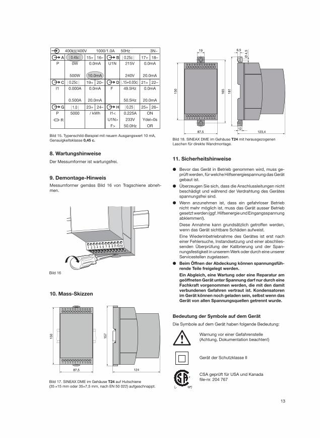
Bild 15. Typenschild-Beispiel mit neuem Ausgangswert 10 mA,
Genauigkeitsklasse 0,45 c.
8. Wartungshinweise
Der Messumformer ist wartungsfrei.
9. Demontage-Hinweis
Messumformer gemäss Bild 16 von Tragschiene abneh-
men.
1 2 3 4 5 6 7 8 9 1113 14
Bild 16
1 2 3 4 5 6 7 8 9 11 13 14
15 16 17 18 19 20 21 22 23 24 25 26
15
0
123,487,5
16
5
6,5
Ø 4
,5
12
19
18
1
Bild 18. SINEAX DME im Gehäuse T24 mit herausgezogenen
Laschen für direkte Wandmontage.
Bild 17. SINEAX DME im Gehäuse T24 auf Hutschiene
(35 ×15 mm oder 35×7,5 mm, nach EN 50 022) aufgeschnappt.
1 2 3 4 5 6 7 8 9 11 13 14
15 16 17 18 19 20 21 22 23 24 25 26
15
0
15
7
12487,5
10. Mass-Skizzen
11. Sicherheitshinweise
● Bevor das Gerät in Betrieb genommen wird, muss ge-
prüft werden, für welche Hilfsenergiespannung das Gerät
gebaut ist.
● Überzeugen Sie sich, dass die Anschlussleitungen nicht
beschädigt und während der Verdrahtung des Gerätes
spannungsfrei sind.
● Wenn anzunehmen ist, dass ein gefahrloser Betrieb
nicht mehr möglich ist, muss das Gerät ausser Betrieb
gesetzt werden (ggf. Hilfsenergie und Eingangsspannung
abklemmen!).
Diese Annahme kann grundsätzlich getroffen werden,
wenn das Gerät sichtbare Schäden aufweist.
Eine Wiederinbetriebnahme des Gerätes ist erst nach
einer Fehlersuche, Instandsetzung und einer abschlies-
senden Überprüfung der Kalibrierung und der Span-
nungsfestigkeit in unserem Werk oder durch eine unserer
Servicestellen zugelassen.
● Beim Öffnen der Abdeckung können spannungsfüh-
rende Teile freigelegt werden.
Ein Abgleich, eine Wartung oder eine Reparatur am
geöffneten Gerät unter Spannung darf nur durch eine
Fachkraft vorgenommen werden, die mit den damit
verbundenen Gefahren vertraut ist. Kondensatoren
im Gerät können noch geladen sein, selbst wenn das
Gerät von allen Spannungsquellen getrennt wurde.
Bedeutung der Symbole auf dem Gerät
Die Symbole auf dem Gerät haben folgende Bedeutung:
Warnung vor einer Gefahrenstelle
(Achtung, Dokumentation beachten!)
Gerät der Schutzklasse II
CSA geprüft für USA und Kanada
fi le-nr. 204 767
14
Mode d’emploi
Convertisseurs de mesure multiples programmables
SINEAX DME 424/442
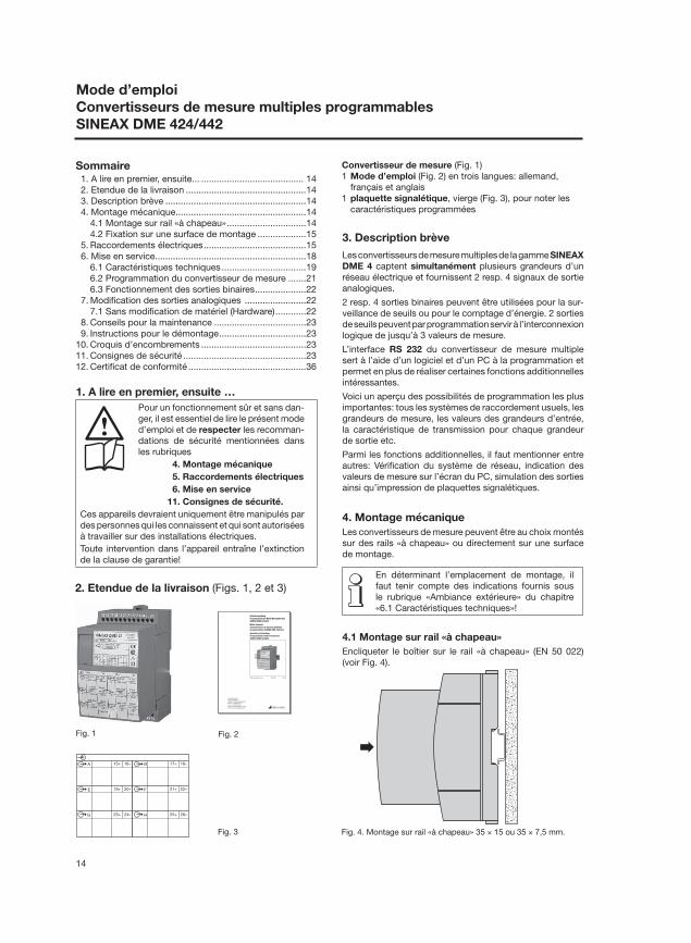
2. Etendue de la livraison (Figs. 1, 2 et 3)
Sommaire 1. A lire en premier, ensuite... ........................................ 14
2. Etendue de la livraison ...............................................14
3. Description brève .......................................................14
4. Montage mécanique ...................................................14
4.1 Montage sur rail «à chapeau» ...............................14
4.2 Fixation sur une surface de montage ...................15
5. Raccordements électriques ........................................15
6. Mise en service ...........................................................18
6.1 Caractéristiques techniques .................................19
6.2 Programmation du convertisseur de mesure .......21
6.3 Fonctionnement des sorties binaires ....................22
7. Modifi cation des sorties analogiques ........................22
7.1 Sans modifi cation de matériel (Hardware) ............22
8. Conseils pour la maintenance ....................................23
9. Instructions pour le démontage ..................................23
10. Croquis d’encombrements .........................................23
11. Consignes de sécurité ................................................23
12. Certifi cat de conformité ..............................................36
Convertisseur de mesure (Fig. 1)
1 Mode d’emploi (Fig. 2) en trois langues: allemand,
français et anglais
1 plaquette signalétique, vierge (Fig. 3), pour noter les
caractéristiques programmées
Fig. 1 Fig. 2
3. Description brève
Les convertisseurs de mesure multiples de la gamme SINEAX
DME 4 captent simultanément plusieurs grandeurs d’un
réseau électrique et fournissent 2 resp. 4 signaux de sortie
analogiques.
2 resp. 4 sorties binaires peuvent être utilisées pour la sur-
veillance de seuils ou pour le comptage d’énergie. 2 sorties
de seuils peuvent par programmation servir à l’interconnexion
logique de jusqu’à 3 valeurs de mesure.
L’interface RS 232 du convertisseur de mesure multiple
sert à l’aide d’un logiciel et d’un PC à la programmation et
permet en plus de réaliser certaines fonctions additionnelles
intéressantes.
Voici un aperçu des possibilités de programmation les plus
importantes: tous les systèmes de raccordement usuels, les
grandeurs de mesure, les valeurs des grandeurs d’entrée,
la caractéristique de transmission pour chaque grandeur
de sortie etc.
Parmi les fonctions additionnelles, il faut mentionner entre
autres: Vérifi cation du système de réseau, indication des
valeurs de mesure sur l’écran du PC, simulation des sorties
ainsi qu’impression de plaquettes signalétiques.
4. Montage mécanique
Les convertisseurs de mesure peuvent être au choix montés
sur des rails «à chapeau» ou directement sur une surface
de montage.
En déterminant l’emplacement de montage, il
faut tenir compte des indications fournis sous
le rubrique «Ambiance extérieure» du chapitre
«6.1 Caractéristiques techniques»!
4.1 Montage sur rail «à chapeau»
Encliqueter le boîtier sur le rail «à chapeau» (EN 50 022)
(voir Fig. 4).
Fig. 4. Montage sur rail «à chapeau» 35 × 15 ou 35 × 7,5 mm.
Camille Bauer AG
Aargauerstrasse 7
CH-5610 Wohlen/Switzerland
Phone +41 56 618 21 11
Fax +41 56 618 24 58
e-Mail: [email protected]
http://www.camillebauer.com
DME 424/442 B d-f-e 122 250 03.08
BetriebsanleitungProgrammierbare Multi-MessumformerSINEAX DME 424/442
Mode d’emploiConvertisseurs de mesure multiplesprogrammables SINEAX DME 424/442
Operating InstructionsProgrammable multi-transducersSINEAX DME 424/442
Fig. 3
15+ 16–A 17+ 18–B
19+ 20–E 21+ 22–F
23+ 24–G 25+ 26–H
1. A lire en premier, ensuite …
Pour un fonctionnement sûr et sans dan-
ger, il est essentiel de lire le présent mode
d’emploi et de respecter les recomman-
dations de sécurité mentionnées dans
les rubriques
4. Montage mécanique
5. Raccordements électriques
6. Mise en service
11. Consignes de sécurité.
Ces appareils devraient uniquement être manipulés par
des personnes qui les connaissent et qui sont autorisées
à travailler sur des installations électriques.
Toute intervention dans l’appareil entraîne l’extinction
de la clause de garantie!
15
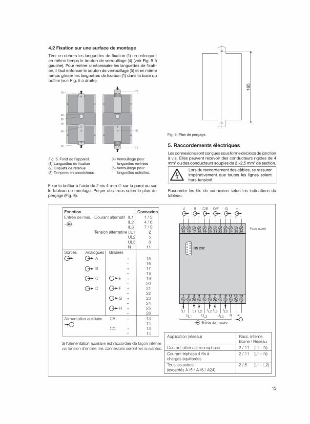
4.2 Fixation sur une surface de montage
Tirer en dehors les languettes de fi xation (1) en enfonçant
en même temps le bouton de verrouillage (4) (voir Fig. 5 à
gauche). Pour rentrer si nécessaire les languettes de fi xati-
on, il faut enfoncer le bouton de verrouillage (5) et en même
temps glisser les languettes de fi xation (1) dans la base du
boîtier (voir Fig. 5 à droite).
Fig. 5. Fond de l’appareil.
(1) Languettes de fi xation
(2) Cliquets de retenue
(3) Tampons en caoutchouc
(4) Verrouillage pour
languettes rentrées
(5) Verrouillage pour
languettes extraites.
Fixer le boîtier à l’aide de 2 vis 4 mm ∅ sur la paroi ou sur
le tableau de montage. Perçer des trous selon le plan de
perçage (Fig. 6).
Fig. 6. Plan de perçage.
5. Raccordements électriques
Les connexions sont conçues sous forme de blocs de jonction
à vis. Elles peuvent recevoir des conducteurs rigides de 4
mm2 ou des conducteurs souples de 2 ×2,5 mm2 de section.
Lors du raccordement des câbles, se rassurer
impérativement que toutes les lignes soient
hors tension!
Raccorder les fi ls de connexion selon les indications du
tableau.
Fonction ConnexionEntrée de mes. Courant alternatif IL1 1 / 3
IL2 4 / 6
IL3 7 / 9
Tension alternative UL1 2
UL2 5
UL3 8
N 11
Sorties Analogues Binaires
A + 15
– 16
B + 17
– 18
C E + 19
– 20
D F + 21
– 22
G + 23
– 24
H + 25
– 26
Alimentation auxiliaire CA ~ 13
~ 14
CC + 13
– 14
Si l’alimentation auxiliaire est raccordée de façon interne
via tension d’entrée, les connexions seront les suivantes:
Application (réseau) Racc. interne
Borne / Réseau
Courant alternatif monophasé 2 / 11 (L1 – N)
Courant triphasé 4 fils à 2 / 11 (L1 – N)
charges équilibrées
Tous les autres 2 / 5 (L1 – L2)
(exceptés A15 / A16 / A24)
2221201918171615
87654321
26252423
1413119
–+ + + + + +– – – –
A
–
B C/E D/F G H
UL2UL1 UL3
IL1 IL2 IL3N
RS 232
Face avant
IL1 IL2 IL3
Entrée de mesure
–
(1)
(2)
(3)
(2)
(4)
(1)
(1)
(1)
(5)
16
5
16
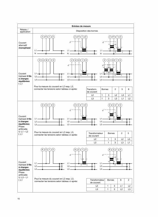
Entrées de mesure
Réseau / application Disposition des bornes
L1
N
11 312
Courant
alternatif
monophasé
L1
5 31
L1
k l
K L
2 5 31
L1
v
V
u
Uk l
K L
2 5 312
L2
L3
L2
L3
L2
L3
Courant
triphasé 3 fils
à charges
équilibrées
Phase
artificielle
U: L1 – L2
I: L1
L1
L2
L3
5 182 3
L1
L2
L3
k l
K L
5 182 3
L1
L2
L3
u
U
v
V
v
V
u
Uk l
K L
5 182 3
Courant
triphasé 3 fils
à charges
équilibrées
I: L1
Pour la mesure du courant en L2 resp. L3,
connecter les tensions selon tableau ci-après:
Pour la mesure du courant en L2 resp. L3,
connecter les tensions selon tableau ci-après:
L1
N
k l
K L
2 11 31
L1
N
v
V
u
Uk l
K L
2 11 31
L1
2 31
L1
k l
K L
8 2 31
L1
v
V
u
U
k l
K L
8 2 318
L2
L3
L2
L3
L2
L3
Courant
triphasé 3 fils
à charges
équilibrées
Phase
artificielle
U: L3 – L1
I: L1Pour la mesure du courant en L2 resp. L3,
connecter les tensions selon tableau ci-après:
Transform. Bornes 2 5 8
de courant
L2 1 3 L2 L3 L1
L3 1 3 L3 L1 L2
Transformateur Bornes 2 5
de courant
L2 1 3 L2 L3
L3 1 3 L3 L1
Transformateur Bornes 8 2
de courant
L2 1 3 L1 L2
L3 1 3 L2 L3
17
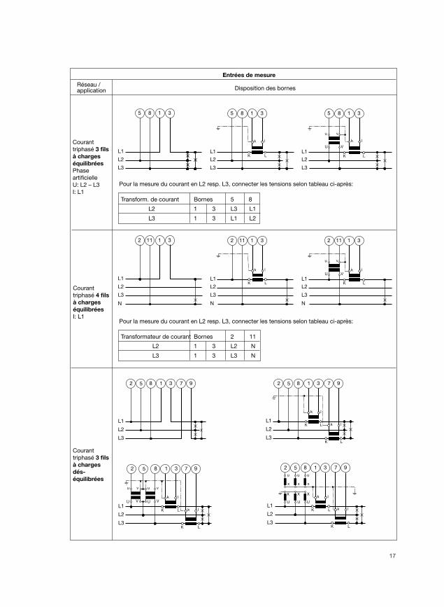
Entrées de mesure
Réseau / application Disposition des bornes
Courant
triphasé 3 fils
à charges
dés-
équilibrées
L1
L2
L3
5 182 3 7 9
L1
L2
L3
k l
K L k l
K L
5 182 3 7 9
L1
L2
L3
u
U
v
V
v
V
u
Uk l
K L k l
K L
5 182 3 7 9
L1
L2
L3
k l
K L k l
K L
xxx
uuu
XXX
UU U
5 182 3 7 9
L1
N
11 31
L1
N
k l
K L
2 11 31
L1
v
V
u
Uk l
K L
2 11 312
L2
L3
L2
L3
N
L2
L3
Courant
triphasé 4 fils
à charges
équilibrées
I: L1
L1
8 31
L1
k l
K L
5 8 31
L1
v
V
u
U
k l
K L
5 8 315
L2
L3
L2
L3
L2
L3
Courant
triphasé 3 fils
à charges
équilibrées
Phase
artificielle
U: L2 – L3
I: L1
Pour la mesure du courant en L2 resp. L3, connecter les tensions selon tableau ci-après:
Transform. de courant Bornes 5 8
L2 1 3 L3 L1
L3 1 3 L1 L2
Pour la mesure du courant en L2 resp. L3, connecter les tensions selon tableau ci-après:
Transformateur de courant Bornes 2 11
L2 1 3 L2 N
L3 1 3 L3 N
18
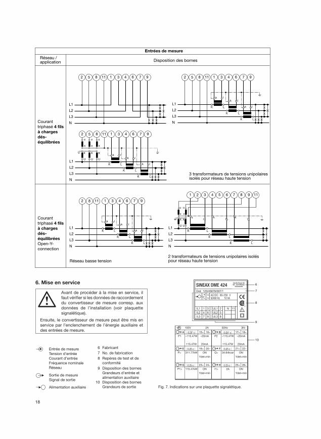
Fig. 7. Indications sur une plaquette signalétique.
Entrées de mesure
Réseau / application Disposition des bornes
Courant
triphasé 4 fils
à charges
dés-
équilibrées
Courant
triphasé 4 fils
à charges
dés-
équilibrées
Open-Y-
connection
L1
L2
L3
N
5 1182 1 3 4 6 7 9
L1
L2
L3
k l
K L
k l
K L
k l
K L
N
5 1182 1 3 4 6 7 9
L1
L2
L3
k l
K L
k l
K L
k l
K L
N
xxx
uuu
XXX
UU U
5 1182 1 3 4 6 7 9
3 transformateurs de tensions unipolairesisolés pour réseau haute tension
L1
L2
L3
k l
K L
k l
K L
k l
K L
N
82 1 3 4 6 7 911
L1
L2
L3
kl
K
k l
K L
k l
K L
xx
uu
X
U
2 431 5 6 7 8 9 11
X
U
L
Réseau basse tension2 transformateurs de tensions unipolaires isoléspour réseau haute tension
N
| 0.25* c | | 0.25* c |
| 0.25 c | | 0.25 c |
| 0.25 c | | 0.25 c |
P1 –115.47W
115.47W
–20mA
20mA
15+ 16–A
100V 2A 50Hz 3N~
P2 –115.47W
115.47W
–20mA
20mA
17+ 18–B
19+ 20–E 21+ 22–FP> 311.77kW ON Q> 34.64kvar ON
Ydel=min Ydel=min
23+ 24–G 25+ 26–H
P1> 115.47kW ON I1> 2A ON
Ydel=min Ydel=min
6
7
8
9
10
SINEAX DME 424Camille Bauer AGCH - 5610 Wohlen
Switzerland
Ord: 123/45679/007/1
AC/DC 85-230 V50/60 Hz 10 VA
IL1
IL2
IL3
1
4
7
3
6
9
UL1
UL2
UL3
2
5
8
N 11
13
14
6. Mise en service
Avant de procéder à la mise en service, il
faut vérifi er si les données de raccordement
du convertisseur de mesure corresp. aux
données de l’installation (voir plaquette
signalétique).
Ensuite, le convertisseur de mesure peut être mis en
service par l’enclenchement de l’énergie auxiliaire et
des entrées de mesure.
Entrée de mesure
Tension d’entrée
Courant d’entrée
Fréquence nominale
Réseau
Sortie de mesure
Signal de sortie
Alimentation auxiliaire
6 Fabricant
7 No. de fabrication
8 Repères de test et de
conformité
9 Disposition des bornes
Grandeurs d’entrée et
alimentation auxiliaire
10 Disposition des bornes
Grandeurs de sortie
19
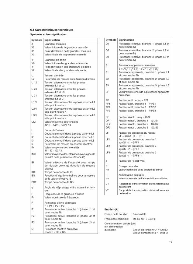
6.1 Caractéristiques techniques
Symboles et leur signifi cation
Symbole Signifi cation
X Grandeur mesurée
X0 Valeur initiale de la grandeur mesurée
X1 Point d’infl exion de la grandeur mesurée
X2 Valeur fi nale de la grandeur mesurée
Y Grandeur de sortie
Y0 Valeur initiale des grandeurs de sortie
Y1 Point d’infl exion des grandeurs de sortie
Y2 Valeur fi nale des grandeurs de sortie
U Tension d’entrée
Ur Paramètre de mesure de la tension d’entrée
U 12 Tension alternative entre les phases
externes L1 et L2
U 23 Tension alternative entre les phases
externes L2 et L3
U 31 Tension alternative entre les phases
externes L3 et L1
U1N Tension alternative entre la phase externe L1
et le point neutre N
U2N Tension alternative entre la phase externe L2
et le point neutre N
U3N Tension alternative entre la phase externe L3
et le point neutre N
UM Valeur moyenne des tensions
(U1N + U2N + U3N) / 3
I Courant d’entrée
I1 Courant alternatif dans la phase externe L1
I2 Courant alternatif dans la phase externe L2
I3 Courant alternatif dans la phase externe L3
Ir Paramètre de mesure du courant d’entrée
IM Valeur moyenne des intensités
(I1 + I2 + I3) / 3
IMS Valeur moyenne des intensités avec signe de
polarité de la puissance effi cace (P)
IB Valeur effective de l’intensité avec temps
de réglage prolongé (fonction de mesure
bilame)
IBT Temps de réponse de IB
BS Fonction d’aiguille entraînée pour la mesure
de la valeur effective IB
BST Temps de réponse de BS
ϕ Angle de déphasage entre courant et ten-
sion
F Fréquence de la grandeur d’entrée
Fn Valeur nominale de fréquence
P Puissance active du réseau
P = P1 + P2 + P3
P1 Puissance active, branche 1 (phase L1 et
point neutre N)
P2 Puissance active, branche 2 (phase L2 et
point neutre N)
P3 Puissance active, branche 3 (phase L3 et
point neutre N)
Q Puissance réactive du réseau
Q = Q1 + Q2 + Q3
Symbole Signifi cation
Q1 Puissance réactive, branche 1 (phase L1 et
point neutre N)
Q2 Puissance réactive, branche 2 (phase L2 et
point neutre N)
Q3 Puissance réactive, branche 3 (phase L3 et
point neutre N)
S Puissance apparente du réseau
S = √ I12 + I
22 + I
32 · √ U
12 + U
22 + U
32
S1 Puissance apparente, branche 1 (phase L1
et point neutre N)
S2 Puissance apparente, branche 2 (phase L2
et point neutre N)
S3 Puissance apparente, branche 3 (phase L3
et point neutre N)
Sr Valeur de référence de la puissance apparente
du réseau
PF Facteur actif cosϕ = P/S
PF1 Facteur actif, branche 1 P1/S1
PF2 Facteur actif, branche 2 P2/S2
PF3 Facteur actif, branche 3 P3/S3
QF Facteur réactif sinϕ = Q/S
QF1 Facteur réactif, branche 1 Q1/S1
QF2 Facteur réactif, branche 2 Q2/S2
QF3 Facteur réactif, branche 3 Q3/S3
LF Facteur de puissance du réseau
LF = sgnQ · (1 – | PF | )LF1 Facteur de puissance, branche 1
sgnQ1 · (1 – | PF1 | )LF2 Facteur de puissance, branche 2
sgnQ2 · (1 – | PF2 | )LF3 Facteur de puissance, branche 3
sgnQ3 · (1 – | PF3 | )
c Facteur de l’écart type
R Charge de sortie
Rn Valeur nominale de la charge de sortie
H Alimentation auxiliaire
Hn Valeur nominale de l’alimentation auxiliaire
CT Rapport de transformation du transformateur
de courant
VT Rapport de transformation du transformateur
de tension
Entrée
Forme de la courbe: Sinusoïdale
Fréquence nominale: 50, 60 ou 16 2/3 Hz
Consommation propre [VA]
(en alimentation
auxiliaire): Circuit de tension: U2 / 400 kΩ
Circuit d’intensité: ≤ I2 · 0,01 Ω
20
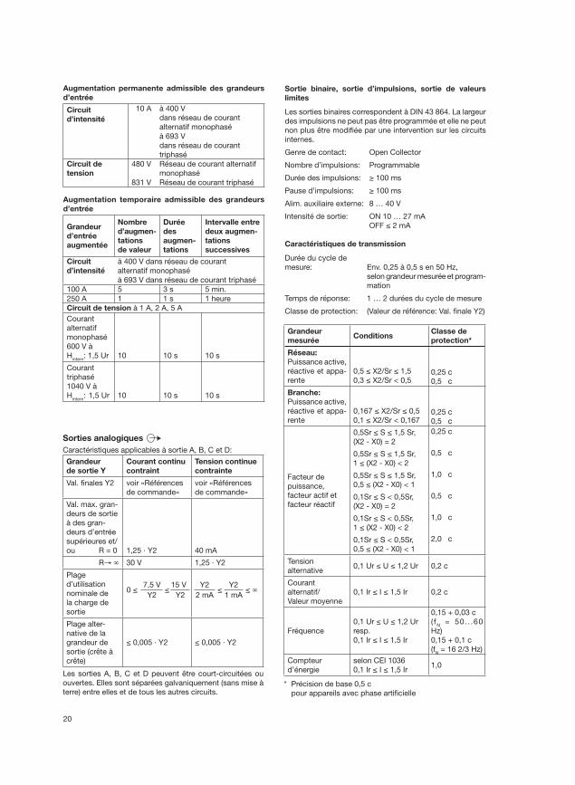
Augmentation permanente admissible des grandeurs
d’entrée
Circuit
d’intensité
10 A à 400 V
dans réseau de courant
alternatif monophasé
à 693 V
dans réseau de courant
triphasé
Circuit de
tension
480 V Réseau de courant alternatif
monophasé
831 V Réseau de courant triphasé
Augmentation temporaire admissible des grandeurs
d’entrée
Grandeur
d’entrée
augmentée
Nombre
d’augmen-
tations
de valeur
Durée
des
augmen-
tations
Intervalle entre
deux augmen-
tations
successives
Circuit
d’intensité
à 400 V dans réseau de courant
alternatif monophasé
à 693 V dans réseau de courant triphasé
100 A 5 3 s 5 min.
250 A 1 1 s 1 heure
Circuit de tension à 1 A, 2 A, 5 A
Courant
alternatif
monophasé
600 V à
Hintern
: 1,5 Ur 10 10 s 10 s
Courant
triphasé
1040 V à
Hintern
: 1,5 Ur 10 10 s 10 s
Sorties analogiques
Caractéristiques applicables à sortie A, B, C et D:
Grandeur
de sortie Y
Courant continu
contraint
Tension continue
contrainte
Val. fi nales Y2 voir «Références
de commande»
voir «Références
de commande»
Val. max. gran-
deurs de sortie
à des gran-
deurs d’entrée
supérieures et/
ou R = 0 1,25 · Y2 40 mA
R→ ∞ 30 V 1,25 · Y2
Plage
d’utilisation
nominale de
la charge de
sortie
0 ≤7,5 V
≤15 V
Y2 Y2
Y2 ≤
Y2 ≤ ∞
2 mA 1 mA
Plage alter-
native de la
grandeur de
sortie (crête à
crête)
≤ 0,005 · Y2 ≤ 0,005 · Y2
Les sorties A, B, C et D peuvent être court-circuitées ou
ouvertes. Elles sont séparées galvaniquement (sans mise à
terre) entre elles et de tous les autres circuits.
Sortie binaire, sortie d’impulsions, sortie de valeurs
limites
Les sorties binaires correspondent à DIN 43 864. La largeur
des impulsions ne peut pas être programmée et elle ne peut
non plus être modifi ée par une intervention sur les circuits
internes.
Genre de contact: Open Collector
Nombre d’impulsions: Programmable
Durée des impulsions: ≥ 100 ms
Pause d’impulsions: ≥ 100 ms
Alim. auxiliaire externe: 8 … 40 V
Intensité de sortie: ON 10 … 27 mA
OFF ≤ 2 mA
Caractéristiques de transmission
Durée du cycle de
mesure: Env. 0,25 à 0,5 s en 50 Hz,
selon grandeur mesurée et program-
mation
Temps de réponse: 1 … 2 durées du cycle de mesure
Classe de protection: (Valeur de référence: Val. fi nale Y2)
Grandeur
mesuréeConditions
Classe de
protection*
Réseau:
Puissance active,
réactive et appa-
rente
0,5 ≤ X2/Sr ≤ 1,5
0,3 ≤ X2/Sr < 0,50,25 c
0,5 c
Branche:
Puissance active,
réactive et appa-
rente
0,167 ≤ X2/Sr ≤ 0,5
0,1 ≤ X2/Sr < 0,1670,25 c
0,5 c
Facteur de
puissance,
facteur actif et
facteur réactif
0,5Sr ≤ S ≤ 1,5 Sr,
(X2 - X0) = 2
0,25 c
0,5Sr ≤ S ≤ 1,5 Sr,
1 ≤ (X2 - X0) < 2
0,5 c
0,5Sr ≤ S ≤ 1,5 Sr,
0,5 ≤ (X2 - X0) < 1
1,0 c
0,1Sr ≤ S < 0,5Sr,
(X2 - X0) = 2
0,5 c
0,1Sr ≤ S < 0,5Sr,
1 ≤ (X2 - X0) < 2
1,0 c
0,1Sr ≤ S < 0,5Sr,
0,5 ≤ (X2 - X0) < 1
2,0 c
Tension
alternative0,1 Ur ≤ U ≤ 1,2 Ur 0,2 c
Courant
alternatif/
Valeur moyenne
0,1 Ir ≤ I ≤ 1,5 Ir 0,2 c
Fréquence
0,1 Ur ≤ U ≤ 1,2 Ur
resp.
0,1 Ir ≤ I ≤ 1,5 Ir
0,15 + 0,03 c
( fN = 50. . .60
Hz)
0,15 + 0,1 c
(fN = 16 2/3 Hz)
Compteur
d’énergie
selon CEI 1036
0,1 Ir ≤ I ≤ 1,5 Ir1,0
* Précision de base 0,5 c
pour appareils avec phase artifi cielle
21
Y
X
Valeurs limites de laplage de réponse
X0/Y0
X2/Y2
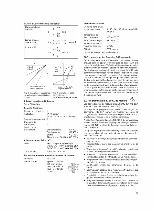
Fig. 9. Exemple des possi-
bilités de réglage
caractéristique à ligne brisée.
Fig. 8. Exemple des possibilités
de réglage avec caractéristique
linéaire.
Effets et grandeurs d’infl uence
Selon EN 60 688
Sécurité électrique
Classe de protection: II
Protection: IP 40, boîtier
IP 20, bornes de raccordement
Degré d’encrassement: 2
Catégorie de
surtension: III
Tension nom.
d’isolement: Entrée tension: CA 400 V
Entrée courant: CA 400 V
Sortie: CC 40 V
Aliment. aux.: CA 400 V, CC 230 V
Alimentation auxiliaire
Tension: Selon plaquette signalétique
DC/AC 24… 60 V examiné CSA
DC/AC 85…230 V examiné CSA
Consommation: ≤ 9 W resp. ≤ 10 VA
Connecteur de programmation du conv. de mesure
Interface: RS 232 C
Douille DSUB: 9 pôles. L’interface
est galvanique-
ment séparée de
tous les autres
circuits
Ambiance extérieure
Domaine nom. d’utili-
sation pour temp.: 0…15…30…45 °C (groupe d’utili-
sation II)
Température de
fonctionnement –10 à + 55 °C
Temp. de stockage: –40 à + 85 °C
Humidité relative en
moyenne annuelle: ≤ 75%
Altitude: 2000 m max.
Utiliser seulement dans les intérieurs
FCC consentement et Canadian DOC déclaration
Cet appareil a été testé et s’est avéré conforme aux limites
prévues pour les appareils numériques de classe A et à la
partie 15 des règlements FCC et à la réglementation des radio-
interférences du Canadian Department of communications.
Ces limites sont destinées à fournir une protection adéquate
contre les interférences néfastes lorsque l’appareil est utilisé
dans un environnement commercial. Cet appareil génère,
utilise et peut radier une énergie à fréquence radioélectrique;
il est en outre susceptible d’engendrer des interférences avec
les coummunications radio, s’il n’est pas installé et utilisé
conformément aux instructions du mode d’emploi. L’utilisation
de cet appareil dans les zones résidentielles peut causer des
interférences néfastes, auquel cas l’exploitant sera amené à
prendre les dispositions utiles pour palier aux interférences
à ses propres frais.
6.2 Programmation du conv. de mesure
Les convertisseurs de mesure SINEAX DME 424/442 sont
équipés d’une interface RS 232 C (SCI).
Le «Logiciel de programmation SINEAX DME 4» (No. de
commande 146 557) permet de modifi er facilement la
programmation existante d’un appareil pour l’adapter à un
problème de mesure et de le mettre en mémoire.
A cet effet, il faut relier la sortie RS 232 C du convertisseur
à un PC à l’aide d’un câble de programmation (No. de com-
mande 980 179) et alimenter le convertisseur par l’alimen-
tation auxiliaire.
Le logiciel de programmation est conçu selon une structure
par menus claire et conviviale et permet d’exécuter les
fonctions suivantes:
• Sélection et affi chage de la programmation du convertis-
seur raccordé
• Représentation claire des paramètres d’entrée et de
sortie
• Transmission des données modifi ées dans le convertisseur
et pour l’archivage dans un fi chier
• Protection contre une modifi cation non autorisée de la
confi guration grâce à l’introduction d’un mot de passe
• Programmation de tous les systèmes de connexion (con-
fi guration du réseau)
• Modifi cation simple des paramètres d’entrée et de
sortie
• Commutation possible de la mesure des fréquences par
le biais du courant ou de la tension
• Possibilité de remise à zéro de l’aiguille entraînée des
grandeurs de sortie correspondantes
• Programmation des sorties A et B resp. A à D (entrée de
la grandeur, de la valeur fi nale, de la limitation de la valeur
fi nale et de la durée du réglage pour chaque sortie)
95
6 1
CTSRTSDSR
GNDDTRTXDRXD
Facteur c (valeur maximale applicable):
Caractéristiques
linéaires:c =
1 -Y0
ou c = 1Y2
1 -X0
X2
Lignes brisées:
X0 ≤ X ≤ X1 c =Y1 - Y0
·X2
ou c = 1X1 - X0 Y2
X1 < X ≤ X2
c =
1 -Y1
ou c = 1Y2
1 -X1
X2
Y
X
Valeurs limites de la plage de réponse
X0/Y0
X2/Y2
X1/Y1
22
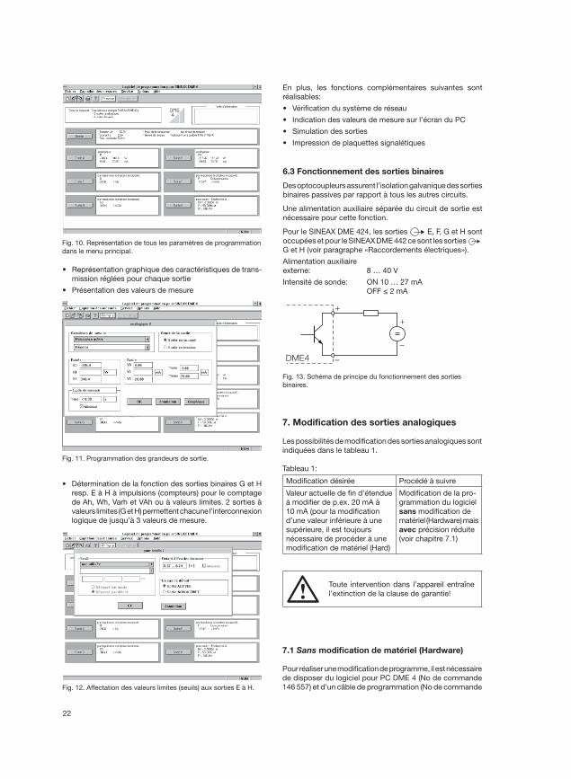
7. Modifi cation des sorties analogiques
Les possibilités de modifi cation des sorties analogiques sont
indiquées dans le tableau 1.
Tableau 1:
Modifi cation désirée Procédé à suivre
Valeur actuelle de fi n d’étendue
à modifi er de p.ex. 20 mA à
10 mA (pour la modifi cation
d’une valeur inférieure à une
supérieure, il est toujours
nécessaire de procéder à une
modifi cation de matériel (Hard)
Modifi cation de la pro-
grammation du logiciel
sans modifi cation de
matériel (Hardware) mais
avec précision réduite
(voir chapitre 7.1)
• Représentation graphique des caractéristiques de trans-
mission réglées pour chaque sortie
• Présentation des valeurs de mesure
Fig. 11. Programmation des grandeurs de sortie.
• Détermination de la fonction des sorties binaires G et H
resp. E à H à impulsions (compteurs) pour le comptage
de Ah, Wh, Varh et VAh ou à valeurs limites. 2 sorties à
valeurs limites (G et H) permettent chacune l’interconnexion
logique de jusqu’à 3 valeurs de mesure.
En plus, les fonctions complémentaires suivantes sont
réalisables:
• Vérifi cation du système de réseau
• Indication des valeurs de mesure sur l’écran du PC
• Simulation des sorties
• Impression de plaquettes signalétiques
6.3 Fonctionnement des sorties binaires
Des optocoupleurs assurent l’isolation galvanique des sorties
binaires passives par rapport à tous les autres circuits.
Une alimentation auxiliaire séparée du circuit de sortie est
nécessaire pour cette fonction.
Pour le SINEAX DME 424, les sorties E, F, G et H sont
occupées et pour le SINEAX DME 442 ce sont les sorties
G et H (voir paragraphe «Raccordements électriques»).
Alimentation auxiliaire
externe: 8 … 40 V
Intensité de sonde: ON 10 … 27 mA
OFF ≤ 2 mA
Fig. 13. Schéma de principe du fonctionnement des sorties
binaires.
Fig. 10. Représentation de tous les paramètres de programmation
dans le menu principal.
Fig. 12. Affectation des valeurs limites (seuils) aux sorties E à H.
+
–DME4
–
+
7.1 Sans modifi cation de matériel (Hardware)
Pour réaliser une modifi cation de programme, il est nécessaire
de disposer du logiciel pour PC DME 4 (No de commande
146 557) et d’un câble de programmation (No de commande
Toute intervention dans l’appareil entraîne
l’extinction de la clause de garantie!
23
| 0.25c | | 0.25c |
| 0.25c | | .15+0.03c|
| 1.0 | | 0.25 |
P 0W
500W
0.0mA
20.0mA
15+ 16–A
400kV/400V 1000/1.0A 50Hz 3N~
U1N 215V
240V
0.0mA
20.0mA
17+ 18–B
19+ 20–C 21+ 22–DI1 0.000A 0.0mA F 49.5Hz 0.0mA
20.0mA
23+ 24–G 25+ 26–H
P 5000 / kWh I1<
U1N>
F>
0.500A 20.0mA 50.5Hz
0.225A
233V
50.0Hz
ON
Ydel=0s
OR
R
| 0.45c | | 0.25c |
| 0.25c | | .15+0.03c |
| 1.0 | | 0.25 |
P 0W
500W
0.0mA
10.0mA
15+ 16–A
400kV/400V 1000/1.0A 50Hz 3N~
U1N 215V
240V
0.0mA
20.0mA
17+ 18–B
19+ 20–C 21+ 22–DI1 0.000A 0.0mA F 49.5Hz 0.0mA
20.0mA
23+ 24–G 25+ 26–H
P 5000 / kWh I1<
U1N>
F>
0.500A 20.0mA 50.5Hz
0.225A
233V
50.0Hz
ON
Ydel=0s
OR
R
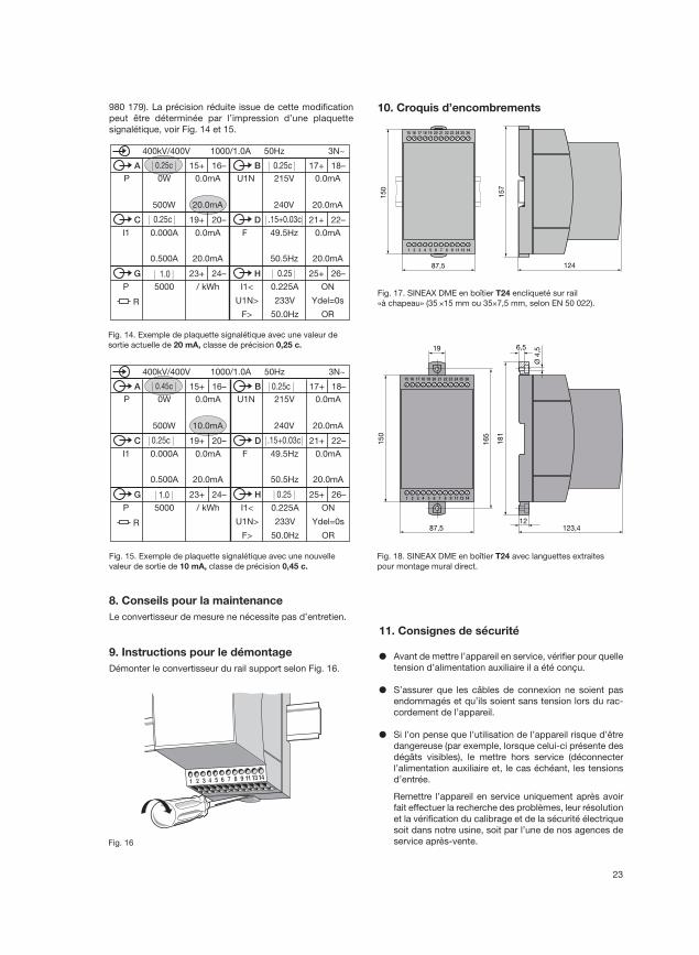
8. Conseils pour la maintenance
Le convertisseur de mesure ne nécessite pas d’entretien.
9. Instructions pour le démontage
Démonter le convertisseur du rail support selon Fig. 16.
1 2 3 4 5 6 7 8 9 1113 14
Fig. 16
Fig. 14. Exemple de plaquette signalétique avec une valeur de
sortie actuelle de 20 mA, classe de précision 0,25 c.
Fig. 15. Exemple de plaquette signalétique avec une nouvelle
valeur de sortie de 10 mA, classe de précision 0,45 c.
980 179). La précision réduite issue de cette modifi cation
peut être déterminée par l’impression d’une plaquette
signalétique, voir Fig. 14 et 15.
1 2 3 4 5 6 7 8 9 11 13 14
15 16 17 18 19 20 21 22 23 24 25 26150
123,487,5
165
6,5
Ø 4
,5
12
19
181
Fig. 18. SINEAX DME en boîtier T24 avec languettes extraites
pour montage mural direct.
Fig. 17. SINEAX DME en boîtier T24 encliqueté sur rail
«à chapeau» (35 ×15 mm ou 35×7,5 mm, selon EN 50 022).
1 2 3 4 5 6 7 8 9 11 13 14
15 16 17 18 19 20 21 22 23 24 25 26
15
0
15
7
12487,5
10. Croquis d’encombrements
11. Consignes de sécurité
● Avant de mettre l’appareil en service, vérifi er pour quelle
tension d’alimentation auxiliaire il a été conçu.
● S’assurer que les câbles de connexion ne soient pas
endommagés et qu’ils soient sans tension lors du rac-
cordement de l’appareil.
● Si l’on pense que l’utilisation de l’appareil risque d’être
dangereuse (par exemple, lorsque celui-ci présente des
dégâts visibles), le mettre hors service (déconnecter
l’alimentation auxiliaire et, le cas échéant, les tensions
d’entrée.
Remettre l’appareil en service uniquement après avoir
fait effectuer la recherche des problèmes, leur résolution
et la vérifi cation du calibrage et de la sécurité électrique
soit dans notre usine, soit par l’une de nos agences de
service après-vente.

24
● Retirer le capot de l’appareil risque de mettre à nu
des pièces sous tension.
Le réglage, l’entretien ou la réparation d’une pièce
lorsque l’appareil est ouvert et sous tension doivent
être réalisés uniquement par une personne qualifi ée
connaissant les risques liés à ce type d’interventions.
En effet, même si l’appareil a été déconnecté de toute
source de tension, les condensateurs de cet appareil
peuvent encore être chargés.
Signifi cation des symboles fi gurant sur l’appareil
Les symboles fi gurant sur l’appareil signifi ent:
Avertit l’utilisateur d’un danger
(Attention, voir la documentation!)
Appareil de classe de protection II
(double isolation)
CSA examiné pour les USA et le Canada
fi le-nr. 204 767
25
Operating Instructions
Programmable multi-transducers SINEAX DME 424/442
2. Scope of supply (Figs. 1, 2 and 3)
Contents 1. Read fi rst and then... ................................................. 25
2. Scope of supply .........................................................25
3. Brief description .........................................................25
4. Physical installation ....................................................25
4.1 Mounting on top-hat rails .....................................25
4.2 Fastening on a mounting surface .........................26
5. Electrical connections ................................................26
6. Commissioning ...........................................................29
6.1 Technical data .......................................................30
6.2 Programming the transducer ................................32
6.3 Operation of the binary outputs ............................33
7. Reconfi guring the analog outputs ..............................33
7.1 Without hardware setting change .........................33
8. Maintenance ...............................................................34
9. Releasing the transducer ............................................34
10. Dimensional drawings.................................................34
11. Safety notes ................................................................34
12. Declaration of conformity ...........................................36
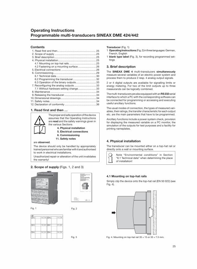
Transducer (Fig. 1)
1 Operating Instructions (Fig. 2) in three languages: German,
French, English
1 blank type label (Fig. 3), for recording programmed set-
tings
Fig. 1 Fig. 2
3. Brief description
The SINEAX DME 4 multi-transducers simultaneously
measure several variables of an electric power system and
process them to produce 2 resp. 4 analog output signals.
2 or 4 digital outputs are available for signalling limits or
energy metering. For two of the limit outputs up to three
measurands can be logically combined.
The multi-transducers are also equipped with an RS 232 serial
interface to which a PC with the corresponding software can
be connected for programming or accessing and executing
useful ancillary functions.
The usual modes of connection, the types of measured vari-
ables, their ratings, the transfer characteristic for each output
etc. are the main parameters that have to be programmed.
Ancillary functions include a power system check, provision
for displaying the measured variable on a PC monitor, the
simulation of the outputs for test purposes and a facility for
printing nameplates.
4. Physical installation
The transducer can be mounted either on a top-hat rail or
directly onto a wall or mounting surface.
Note “Environmental conditions” in Section
“6.1 Technical data” when determining the place
of installation!
4.1 Mounting on top-hat rails
Simply clip the device onto the top-hat rail (EN 50 022) (see
Fig. 4).
Fig. 4. Mounting on top-hat rail 35 × 15 or 35 × 7.5 mm.
Camille Bauer AG
Aargauerstrasse 7
CH-5610 Wohlen/Switzerland
Phone +41 56 618 21 11
Fax +41 56 618 24 58
e-Mail: [email protected]
http://www.camillebauer.com
DME 424/442 B d-f-e 122 250 03.08
BetriebsanleitungProgrammierbare Multi-MessumformerSINEAX DME 424/442
Mode d’emploiConvertisseurs de mesure multiplesprogrammables SINEAX DME 424/442
Operating InstructionsProgrammable multi-transducersSINEAX DME 424/442
Fig. 3
15+ 16–A 17+ 18–B
19+ 20–E 21+ 22–F
23+ 24–G 25+ 26–H
1. Read fi rst and then …
The proper and safe operation of the device
assumes that the Operating Instructions
are read and the safety warnings given in
the various Sections
4. Physical installation
5. Electrical connections
6. Commissioning
11. Safety notes
are observed.
The device should only be handled by appropriately
trained personnel who are familiar with it and authorised
to work in electrical installations.
Unauthorized repair or alteration of the unit invalidates
the warranty!
26
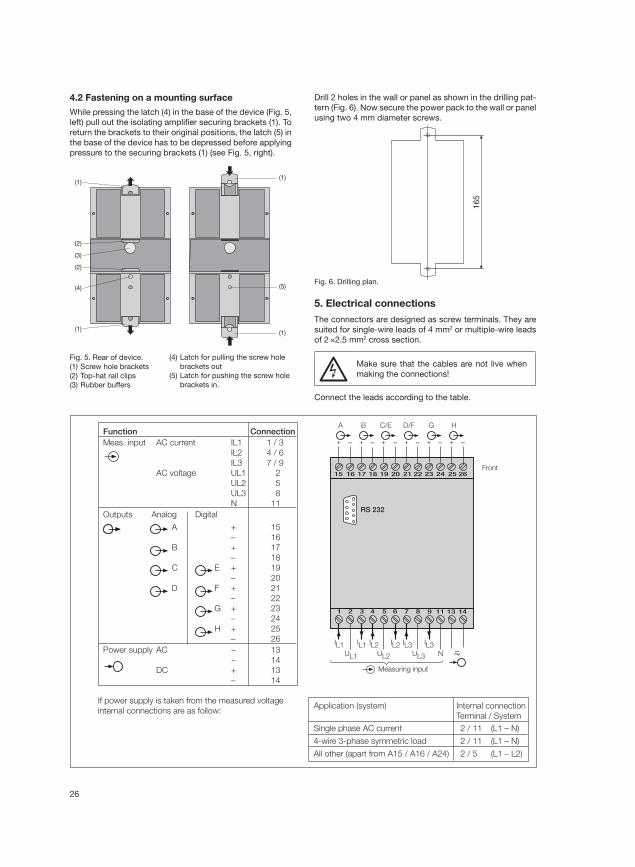
4.2 Fastening on a mounting surface
While pressing the latch (4) in the base of the device (Fig. 5,
left) pull out the isolating amplifi er securing brackets (1). To
return the brackets to their original positions, the latch (5) in
the base of the device has to be depressed before applying
pressure to the securing brackets (1) (see Fig. 5, right).
Fig. 5. Rear of device.
(1) Screw hole brackets
(2) Top-hat rail clips
(3) Rubber buffers
(4) Latch for pulling the screw hole
brackets out
(5) Latch for pushing the screw hole
brackets in.
Drill 2 holes in the wall or panel as shown in the drilling pat-
tern (Fig. 6). Now secure the power pack to the wall or panel
using two 4 mm diameter screws.
Fig. 6. Drilling plan.
5. Electrical connections
The connectors are designed as screw terminals. They are
suited for single-wire leads of 4 mm2 or multiple-wire leads
of 2 ×2.5 mm2 cross section.
Make sure that the cables are not live when
making the connections!
Connect the leads according to the table.
Function ConnectionMeas. input AC current IL1 1 / 3
IL2 4 / 6
IL3 7 / 9
AC voltage UL1 2
UL2 5
UL3 8
N 11
Outputs Analog Digital
A + 15
– 16
B + 17
– 18
C E + 19
– 20
D F + 21
– 22
G + 23
– 24
H + 25
– 26
Power supply AC ~ 13
~ 14
DC + 13
– 14
If power supply is taken from the measured voltage
internal connections are as follow:Application (system) Internal connection
Terminal / System
Single phase AC current 2 / 11 (L1 – N)
4-wire 3-phase symmetric load 2 / 11 (L1 – N)
All other (apart from A15 / A16 / A24) 2 / 5 (L1 – L2)
2221201918171615
87654321
26252423
1413119
–+ + + + + +– – – –
A
–
B C/E D/F G H
UL2UL1 UL3
IL1 IL2 IL3N
RS 232
Front
IL1 IL2 IL3
Measuring input
–
(1)
(2)
(3)
(2)
(4)
(1)
(1)
(1)
(5)
16
5
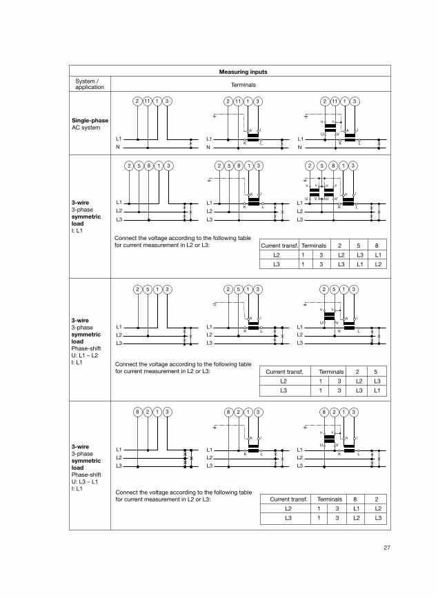
27
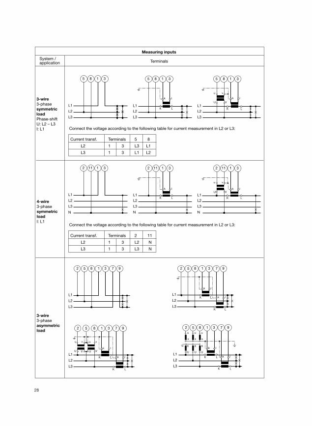
Measuring inputs
System / application Terminals
L1
N
11 312
Single-phase
AC system
L1
5 31
L1
k l
K L
2 5 31
L1
v
V
u
Uk l
K L
2 5 312
L2
L3
L2
L3
L2
L3
3-wire
3-phase
symmetric
load
Phase-shift
U: L1 – L2
I: L1
L1
L2
L3
5 182 3
L1
L2
L3
k l
K L
5 182 3
L1
L2
L3
u
U
v
V
v
V
u
Uk l
K L
5 182 3
3-wire
3-phase
symmetric
load
I: L1
Connect the voltage according to the following table
for current measurement in L2 or L3:
Connect the voltage according to the following table
for current measurement in L2 or L3:
L1
N
k l
K L
2 11 31
L1
N
v
V
u
Uk l
K L
2 11 31
L1
2 31
L1
k l
K L
8 2 31
L1
v
V
u
U
k l
K L
8 2 318
L2
L3
L2
L3
L2
L3
3-wire
3-phase
symmetric
load
Phase-shift
U: L3 – L1
I: L1Connect the voltage according to the following table
for current measurement in L2 or L3:
Current transf. Terminals 2 5 8
L2 1 3 L2 L3 L1
L3 1 3 L3 L1 L2
Current transf. Terminals 2 5
L2 1 3 L2 L3
L3 1 3 L3 L1
Current transf. Terminals 8 2
L2 1 3 L1 L2
L3 1 3 L2 L3
28
Measuring inputs
System / application Terminals
3-wire
3-phase
asymmetric
load
L1
L2
L3
5 182 3 7 9
L1
L2
L3
k l
K L k l
K L
5 182 3 7 9
L1
L2
L3
u
U
v
V
v
V
u
Uk l
K L k l
K L
5 182 3 7 9
L1
L2
L3
k l
K L k l
K L
xxx
uuu
XXX
UU U
5 182 3 7 9
L1
N
11 31
L1
N
k l
K L
2 11 31
L1
v
V
u
Uk l
K L
2 11 312
L2
L3
L2
L3
N
L2
L3
4-wire
3-phase
symmetric
load
I: L1
L1
8 31
L1
k l
K L
5 8 31
L1
v
V
u
U
k l
K L
5 8 315
L2
L3
L2
L3
L2
L3
3-wire
3-phase
symmetric
load
Phase-shift
U: L2 – L3
I: L1 Connect the voltage according to the following table for current measurement in L2 or L3:
Current transf. Terminals 5 8
L2 1 3 L3 L1
L3 1 3 L1 L2
Connect the voltage according to the following table for current measurement in L2 or L3:
Current transf. Terminals 2 11
L2 1 3 L2 N
L3 1 3 L3 N
29
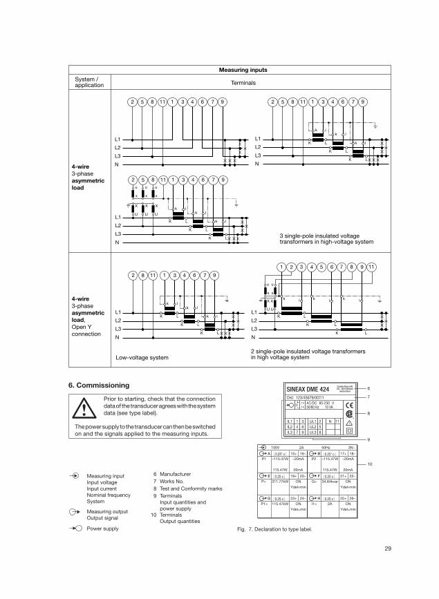
Fig. 7. Declaration to type label.
Measuring inputs
System / application Terminals
4-wire
3-phase
asymmetric
load
4-wire
3-phase
asymmetric
load,
Open Y
connection
3 single-pole insulated voltage transformers in high-voltage system
Low-voltage system2 single-pole insulated voltage transformersin high voltage system
L1
L2
L3
k l
K L
k l
K L
k l
K L
N
5 1182 1 3 4 6 7 9
L1
L2
L3
N
5 1182 1 3 4 6 7 9
L1
L2
L3
k l
K L
k l
K L
k l
K L
N
xxx
uuu
XXX
UU U
5 1182 1 3 4 6 7 9
L1
L2
L3
k l
K
kl
K L
k l
K L
xx
uu
X
U
2 431 5 6 7 8 9 11
X
U
L
N
L1
L2
L3
k l
K L
k l
K L
k l
K L
N
82 1 3 4 6 7 911
| 0.25* c | | 0.25* c |
| 0.25 c | | 0.25 c |
| 0.25 c | | 0.25 c |
P1 –115.47W
115.47W
–20mA
20mA
15+ 16–A
100V 2A 50Hz 3N~
P2 –115.47W
115.47W
–20mA
20mA
17+ 18–B
19+ 20–E 21+ 22–FP> 311.77kW ON Q> 34.64kvar ON
Ydel=min Ydel=min
23+ 24–G 25+ 26–H
P1> 115.47kW ON I1> 2A ON
Ydel=min Ydel=min
6
7
8
9
10
SINEAX DME 424Camille Bauer AGCH - 5610 Wohlen
Switzerland
Ord: 123/45679/007/1
AC/DC 85-230 V50/60 Hz 10 VA
IL1
IL2
IL3
1
4
7
3
6
9
UL1
UL2
UL3
2
5
8
N 11
13
14
6. Commissioning
Prior to starting, check that the connection
data of the transducer agrees with the system
data (see type label).
The power supply to the transducer can then be switched
on and the signals applied to the measuring inputs.
Measuring input
Input voltage
Input current
Nominal frequency
System
Measuring output
Output signal
Power supply
6 Manufacturer
7 Works No.
8 Test and Conformity marks
9 Terminals
Input quantities and
power supply
10 Terminals
Output quantities
30
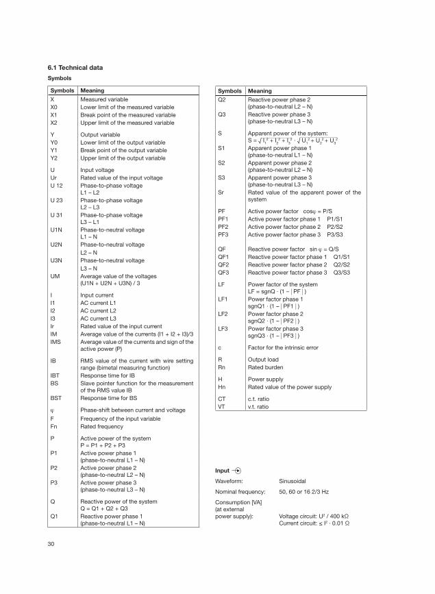
6.1 Technical data
Symbols
Symbols Meaning
X Measured variable
X0 Lower limit of the measured variable
X1 Break point of the measured variable
X2 Upper limit of the measured variable
Y Output variable
Y0 Lower limit of the output variable
Y1 Break point of the output variable
Y2 Upper limit of the output variable
U Input voltage
Ur Rated value of the input voltage
U 12 Phase-to-phase voltage
L1 – L2
U 23 Phase-to-phase voltage
L2 – L3
U 31 Phase-to-phase voltage
L3 – L1
U1N Phase-to-neutral voltage
L1 – N
U2N Phase-to-neutral voltage
L2 – N
U3N Phase-to-neutral voltage
L3 – N
UM Average value of the voltages
(U1N + U2N + U3N) / 3
I Input current
I1 AC current L1
I2 AC current L2
I3 AC current L3
Ir Rated value of the input current
IM Average value of the currents (I1 + I2 + I3)/3
IMS Average value of the currents and sign of the
active power (P)
IB RMS value of the current with wire setting
range (bimetal measuring function)
IBT Response time for IB
BS Slave pointer function for the measurement
of the RMS value IB
BST Response time for BS
ϕ Phase-shift between current and voltage
F Frequency of the input variable
Fn Rated frequency
P Active power of the system
P = P1 + P2 + P3
P1 Active power phase 1
(phase-to-neutral L1 – N)
P2 Active power phase 2
(phase-to-neutral L2 – N)
P3 Active power phase 3
(phase-to-neutral L3 – N)
Q Reactive power of the system
Q = Q1 + Q2 + Q3
Q1 Reactive power phase 1
(phase-to-neutral L1 – N)
Symbols Meaning
Q2 Reactive power phase 2
(phase-to-neutral L2 – N)
Q3 Reactive power phase 3
(phase-to-neutral L3 – N)
S Apparent power of the system:
S = √ I12 + I
22 + I
32 · √ U
12 + U
22 + U
32
S1 Apparent power phase 1
(phase-to-neutral L1 – N)
S2 Apparent power phase 2
(phase-to-neutral L2 – N)
S3 Apparent power phase 3
(phase-to-neutral L3 – N)
Sr Rated value of the apparent power of the
system
PF Active power factor cosϕ = P/S
PF1 Active power factor phase 1 P1/S1
PF2 Active power factor phase 2 P2/S2
PF3 Active power factor phase 3 P3/S3
QF Reactive power factor sin ϕ = Q/S
QF1 Reactive power factor phase 1 Q1/S1
QF2 Reactive power factor phase 2 Q2/S2
QF3 Reactive power factor phase 3 Q3/S3
LF Power factor of the system
LF = sgnQ · (1 – | PF | )LF1 Power factor phase 1
sgnQ1 · (1 – | PF1 | )LF2 Power factor phase 2
sgnQ2 · (1 – | PF2 | )LF3 Power factor phase 3
sgnQ3 · (1 – | PF3 | )
c Factor for the intrinsic error
R Output load
Rn Rated burden
H Power supply
Hn Rated value of the power supply
CT c.t. ratio
VT v.t. ratio
Input
Waveform: Sinusoidal
Nominal frequency: 50, 60 or 16 2/3 Hz
Consumption [VA]
(at external
power supply): Voltage circuit: U2 / 400 kΩ
Current circuit: ≤ I2 · 0.01 Ω
31
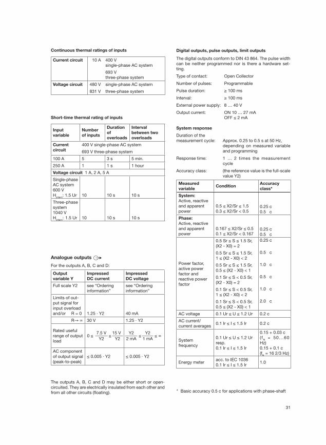
Continuous thermal ratings of inputs
Current circuit 10 A 400 V
single-phase AC system
693 V
three-phase system
Voltage circuit 480 V single-phase AC system
831 V three-phase system
Short-time thermal rating of inputs
Input
variable
Number
of inputs
Duration
of
overloads
Interval
between two
overloads
Current
circuit
400 V single-phase AC system
693 V three-phase system
100 A 5 3 s 5 min.
250 A 1 1 s 1 hour
Voltage circuit 1 A, 2 A, 5 A
Single-phase
AC system
600 V
Hintern
: 1.5 Ur 10 10 s 10 s
Three-phase
system
1040 V
Hintern
: 1.5 Ur 10 10 s 10 s
Analogue outputs
For the outputs A, B, C and D:
Output
variable Y
Impressed
DC current
Impressed
DC voltage
Full scale Y2 see “Ordering
information”
see “Ordering
information”
Limits of out-
put signal for
input overload
and/or R = 0 1.25 · Y2 40 mA
R→ ∞ 30 V 1.25 · Y2
Rated useful
range of output
load
0 ≤7.5 V
≤15 V
Y2 Y2
Y2 ≤
Y2 ≤ ∞
2 mA 1 mA
AC component
of output signal
(peak-to-peak)
≤ 0.005 · Y2 ≤ 0.005 · Y2
The outputs A, B, C and D may be either short or open-
circuited. They are electrically insulated from each other and
from all other circuits (fl oating).
Digital outputs, pulse outputs, limit outputs
The digital outputs conform to DIN 43 864. The pulse width
can be neither programmed nor is there a hardware set-
ting.
Type of contact: Open Collector
Number of pulses: Programmable
Pulse duration: ≥ 100 ms
Interval: ≥ 100 ms
External power supply: 8 … 40 V
Output current: ON 10 … 27 mA
OFF ≤ 2 mA
System response
Duration of the
measurement cycle: Approx. 0.25 to 0.5 s at 50 Hz,
depending on measured variable
and programming
Response time: 1 … 2 times the measurement
cycle
Accuracy class: (the reference value is the full-scale
value Y2)
Measured
variableCondition
Accuracy
class*
System:
Active, reactive
and apparent
power
0.5 ≤ X2/Sr ≤ 1.5
0.3 ≤ X2/Sr < 0.50.25 c
0.5 c
Phase:
Active, reactive
and apparent
power
0.167 ≤ X2/Sr ≤ 0.5
0.1 ≤ X2/Sr < 0.1670.25 c
0.5 c
Power factor,
active power
factor and
reactive power
factor
0.5 Sr ≤ S ≤ 1.5 Sr,
(X2 - X0) = 2
0.25 c
0.5 Sr ≤ S ≤ 1.5 Sr,
1 ≤ (X2 - X0) < 2
0.5 c
0.5 Sr ≤ S ≤ 1.5 Sr,
0.5 ≤ (X2 - X0) < 1
1.0 c
0.1 Sr ≤ S < 0.5 Sr,
(X2 - X0) = 2
0.5 c
0.1 Sr ≤ S < 0.5 Sr,
1 ≤ (X2 - X0) < 2
1.0 c
0.1 Sr ≤ S < 0.5 Sr,
0.5 ≤ (X2 - X0) < 1
2.0 c
AC voltage 0.1 Ur ≤ U ≤ 1.2 Ur 0.2 c
AC current/
current averages0.1 Ir ≤ I ≤ 1.5 Ir 0.2 c
System
frequency
0.1 Ur ≤ U ≤ 1.2 Ur
resp.
0.1 Ir ≤ I ≤ 1.5 Ir
0.15 + 0.03 c
( fN = 50. . .60
Hz)
0.15 + 0.1 c
(fN = 16 2/3 Hz)
Energy meteracc. to IEC 1036
0.1 Ir ≤ I ≤ 1.5 Ir1.0
* Basic accuracy 0.5 c for applications with phase-shaft
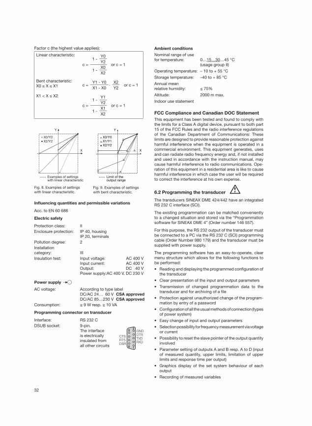
32
Y
X
Examples of settingswith linear characteristic
X0/Y0
X2/Y2
Y
X
Limit of the output range
X0/Y0
X2/Y2
X1/Y1
Fig. 9. Examples of settings
with bent characteristic.
Fig. 8. Examples of settings
with linear characteristic.
Infl uencing quantities and permissible variations
Acc. to EN 60 688
Electric safety
Protection class: II
Enclosure protection: IP 40, housing
IP 20, terminals
Pollution degree: 2
Installation
category: III
Insulation test: Input voltage: AC 400 V
Input current: AC 400 V
Output: DC 40 V
Power supply: AC 400 V, DC 230 V
Power supply
AC voltage: According to type label
DC/AC 24… 60 V CSA approved
DC/AC 85…230 V CSA approved
Consumption: ≤ 9 W resp. ≤ 10 VA
Programming connector on transducer
Interface: RS 232 C
DSUB socket: 9-pin.
The interface
is electrically
insulated from
all other circuits
Ambient conditions
Nominal range of use
for temperature: 0…15…30…45 °C
(usage group II)
Operating temperature: – 10 to + 55 °C
Storage temperature: –40 to + 85 °C
Annual mean
relative humidity: ≤ 75%
Altitude: 2000 m max.
Indoor use statement
FCC Compliance and Canadian DOC Statement
This equipment has been tested and found to comply with
the limits for a Class A digital device, pursuant to both part
15 of the FCC Rules and the radio interference regulations
of the Canadian Department of Communications: These
limits are designed to provide reasonable protection against
harmful interference when the equipment is operated in a
commercial environment. This equipment generates, uses
and can radiate radio frequency energy and, if not installed
and used in accordance with the instruction manual, may
cause harmful interference to radio communications. Ope-
ration of this equipment in a residential area is like to cause
harmful interference in which case the user will be required
to correct the interference at his own expense.
6.2 Programming the transducer
The transducers SINEAX DME 424/442 have an integrated
RS 232 C interface (SCI).
The existing programmation can be matched conveniently
to a changed situation and stored via the “Programmation
software for SINEAX DME 4” (Order number 146 557).
For this purpose, the RS 232 output of the transducer must
be connected to a PC via the RS 232 C (SCI) programming
cable (Order Number 980 179) and the transducer must be
supplied with power supply.
The programming software has an easy-to-operate, clear
menu structure which allows for the following functions to
be performed:
• Reading and displaying the programmed confi guration of
the transducer
• Clear presentation of the input and output parameters
• Transmission of changed programmation data to the
transducer and for archiving of a fi le
• Protection against unauthorized change of the program-
mation by entry of a password
• Confi guration of all the usual methods of connection (types
of power system)
• Easy change of input and output parameters
• Selection possibility for frequency measurement via voltage
or current
• Possibility to reset the slave pointer of the output quantity
involved
• Parameter setting of outputs A and B resp. A to D (input
of measured quantity, upper limits, limitation of upper
limits and response time per output)
• Graphics display of the set system behaviour of each
output
• Recording of measured variables
95
6 1
CTSRTSDSR
GNDDTRTXDRXD
Factor c (the highest value applies):
Linear characteristic:
c =
1 -Y0
or c = 1Y2
1 -X0
X2
Bent characteristic:
X0 ≤ X ≤ X1 c =Y1 - Y0
·X2
or c = 1X1 - X0 Y2
X1 < X ≤ X2
c =
1 -Y1
or c = 1Y2
1 -X1
X2
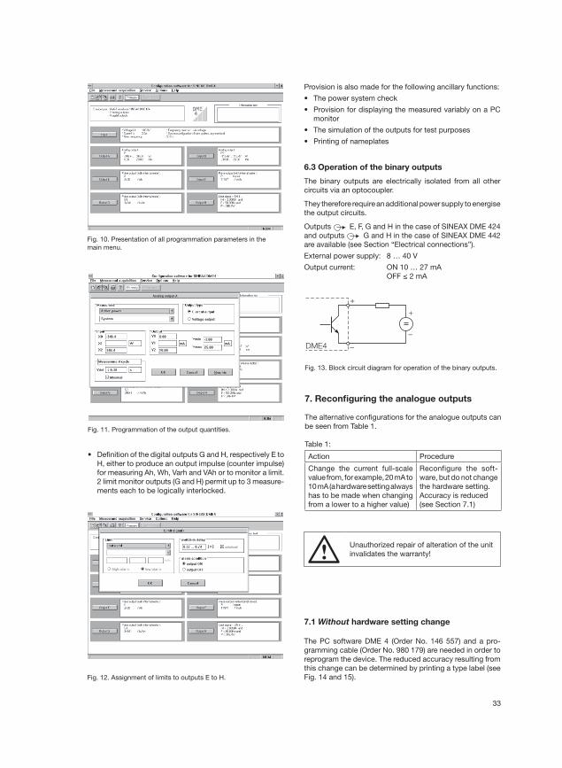
33
Fig. 11. Programmation of the output quantities.
• Defi nition of the digital outputs G and H, respectively E to
H, either to produce an output impulse (counter impulse)
for measuring Ah, Wh, Varh and VAh or to monitor a limit.
2 limit monitor outputs (G and H) permit up to 3 measure-
ments each to be logically interlocked.
Fig. 12. Assignment of limits to outputs E to H.
+
–DME4
–
+
Fig. 13. Block circuit diagram for operation of the binary outputs.
Provision is also made for the following ancillary functions:
• The power system check
• Provision for displaying the measured variably on a PC
monitor
• The simulation of the outputs for test purposes
• Printing of nameplates
6.3 Operation of the binary outputs
The binary outputs are electrically isolated from all other
circuits via an optocoupler.
They therefore require an additional power supply to energise
the output circuits.
Outputs E, F, G and H in the case of SINEAX DME 424
and outputs G and H in the case of SINEAX DME 442
are available (see Section “Electrical connections”).
External power supply: 8 … 40 V
Output current: ON 10 … 27 mA
OFF ≤ 2 mA
Fig. 10. Presentation of all programmation parameters in the
main menu.
7.1 Without hardware setting change
The PC software DME 4 (Order No. 146 557) and a pro-
gramming cable (Order No. 980 179) are needed in order to
reprogram the device. The reduced accuracy resulting from
this change can be determined by printing a type label (see
Fig. 14 and 15).
7. Reconfi guring the analogue outputs
The alternative confi gurations for the analogue outputs can
be seen from Table 1.
Table 1:
Action Procedure
Change the current full-scale
value from, for example, 20 mA to
10 mA (a hardware setting always
has to be made when changing
from a lower to a higher value)
Reconfigure the soft-
ware, but do not change
the hardware setting.
Accuracy is reduced
(see Section 7.1)
Unauthorized repair of alteration of the unit
invalidates the warranty!
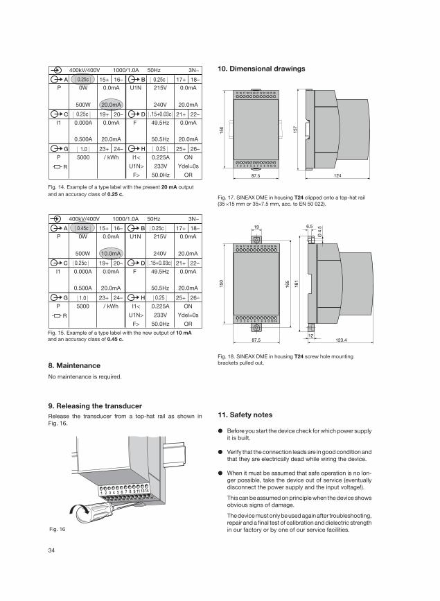
34
8. Maintenance
No maintenance is required.
9. Releasing the transducer
Release the transducer from a top-hat rail as shown in
Fig. 16.
| 0.25c | | 0.25c |
| 0.25c | | .15+0.03c|
| 1.0 | | 0.25 |
P 0W
500W
0.0mA
20.0mA
15+ 16–A
400kV/400V 1000/1.0A 50Hz 3N~
U1N 215V
240V
0.0mA
20.0mA
17+ 18–B
19+ 20–C 21+ 22–DI1 0.000A 0.0mA F 49.5Hz 0.0mA
20.0mA
23+ 24–G 25+ 26–H
P 5000 / kWh I1<
U1N>
F>
0.500A 20.0mA 50.5Hz
0.225A
233V
50.0Hz
ON
Ydel=0s
OR
R
Fig. 14. Example of a type label with the present 20 mA output
and an accuracy class of 0.25 c.
| 0.45c | | 0.25c |
| 0.25c | | .15+0.03c |
| 1.0 | | 0.25 |
P 0W
500W
0.0mA
10.0mA
15+ 16–A
400kV/400V 1000/1.0A 50Hz 3N~
U1N 215V
240V
0.0mA
20.0mA
17+ 18–B
19+ 20–C 21+ 22–DI1 0.000A 0.0mA F 49.5Hz 0.0mA
20.0mA
23+ 24–G 25+ 26–H
P 5000 / kWh I1<
U1N>
F>
0.500A 20.0mA 50.5Hz
0.225A
233V
50.0Hz
ON
Ydel=0s
OR
R
Fig. 15. Example of a type label with the new output of 10 mA
and an accuracy class of 0.45 c.
10. Dimensional drawings
1 2 3 4 5 6 7 8 9 11 13 14
15 16 17 18 19 20 21 22 23 24 25 26
150
123.487.5
165
6.5
Ø 4
.5
12
19
181
Fig. 18. SINEAX DME in housing T24 screw hole mounting
brackets pulled out.
Fig. 17. SINEAX DME in housing T24 clipped onto a top-hat rail
(35 ×15 mm or 35×7.5 mm, acc. to EN 50 022).
1 2 3 4 5 6 7 8 9 11 13 14
15 16 17 18 19 20 21 22 23 24 25 26
150
157
12487.5
1 2 3 4 5 6 7 8 9 1113 14
Fig. 16
11. Safety notes
● Before you start the device check for which power supply
it is built.
● Verify that the connection leads are in good condition and
that they are electrically dead while wiring the device.
● When it must be assumed that safe operation is no lon-
ger possible, take the device out of service (eventually
disconnect the power supply and the input voltage!).
This can be assumed on principle when the device shows
obvious signs of damage.
The device must only be used again after troubleshooting,
repair and a fi nal test of calibration and dielectric strength
in our factory or by one of our service facilities.

35
Meaning of the symbols on the device
The symbols on the device have the following meaning:
Warning of danger
(Caution, see documentation!)
Class II device
CSA approved for USA and Canada
fi le nr. 204 767
● When opening the cover, live parts may be expo-
sed.
Calibration, maintenance or repair with the device
open and live must only be performed by a qualifi ed
person who understands the danger involved. Capa-
citors in the device may still be charged even though
the device has been disconnected from all voltage
sources.

36
12. Konformitätsbescheinigung / Certifi cat de conformité / Declarations of conformity