Embed Size (px)
Citation preview
BETRIEBSANLEITUNG FÜR ROHRBÜNDEL-WÄRMETAUSCHER MANUAL FOR SHELL-AND-TUBE
HEAT EXCHANGERS

2
Alle Rechte vorbehalten. Inhalte dürfen ohne schriftliche Zustimmung des Herstellers weder verbreitet, vervielfältigt, bearbeitet noch an Dritte weitergegeben werden. Vor Gebrauch aufmerksam lesen. Für durch Nichtbeachtung entstehende Schäden können wir keine Haftung übernehmen. Während der Garantiezeit dürfen Änderungen an unseren Produkten nur durch unsere Monteure und mit unserem Einverständnis vorgenommen werden. Falls Sie, abweichend von der Auftragsbestätigung, unsere Produkte für andere Betriebsverhältnisse einsetzen wollen, holen Sie bitte unser Einverständnis ein. Anderenfalls entfällt die Garantie für dieses Produkt. Ausgabe: 27. April 2017 Erstellt: Mühle Geprüft: Rathsmann All rights reserved. Contents may not be disseminated, reproduced, edited or transmitted to third parties without the written consent of the manufacturer. Read carefully before use. We can not accept any liability for damages caused by nonobservance. During the warranty period, modifications of our products may only be made by our installers and with our consent. If, contrary to the order confirmation, you wish to use our products for other operating conditions, please obtain our consent. Without our consent the warranty for this product expires. Edition: 27th of April 2017 Created: Mühle Approved: Rathsmann © ZPM Zahnradpumpenfabrik Mannheim GmbH Friesenheimer Str. 3-7 DE-68169 Mannheim Tel.:+49 / (0)621 321 52 - 0 Fax::+49 / (0)621 52 - 24 www.zpm-systeme.de Mail: [email protected]
3
Inhaltsverzeichnis
1. Allgemeines .................................................................................................................... 5
2. Kennzeichnung von Hinweisen in der Betriebsanleitung ................................................. 5
3. Sicherheit ....................................................................................................................... 5
3.1 Personenqualifikation und Schulung ........................................................................... 5
3.2 Gefahren bei Nichtbeachtung der Sicherheitshinweise ............................................... 6
3.3 Sicherheitsbewusstes Arbeiten ................................................................................... 6
3.4 Sicherheitshinweise für den Betreiber/Bediener .......................................................... 6
3.5 Sicherheit bei Wartungs-, Inspektions- und Montagearbeiten ..................................... 6
3.6 Eigenmächtiger Umbau und Ersatzteilherstellung ....................................................... 7
3.7 Unzulässige Betriebsweisen ....................................................................................... 7
4. Beschreibung ................................................................................................................. 8
4.1 Konstruktiver Aufbau und Funktionsweise .................................................................. 8
4.2 Baureihen ..................................................................................................................10
4.3 Leistungsangaben .....................................................................................................13
4.4 Einsatzgebiete ...........................................................................................................14
5. Transport .......................................................................................................................14
6. Lagerung .......................................................................................................................15
7. Aufstellung ....................................................................................................................15
7.1 Rohrleitungen ............................................................................................................17
8. Inbetriebnahme .............................................................................................................17
8.1 Umschalten von Doppelwärmetauschern nach der Inbetriebnahme ...........................18
9. Außerbetriebnahme .......................................................................................................19
10. Wartung und Instandhaltung ......................................................................................20
10.1 Reinigen des Wärmetauschers ..................................................................................21
10.2 Ortung von Kühlrohrleckage ......................................................................................23
10.3 Verschließen undichter Kühlrohre ..............................................................................24
10.4 Austritt von Medium am Stopfbuchsring .....................................................................24
10.5 Sonstige Leckage ......................................................................................................25
11. Störungen, Ursachen und Beseitigung .......................................................................26
4
Table of contents
1. General .........................................................................................................................27
2. Marking of manual contents ..........................................................................................27
3. Safety ............................................................................................................................27
3.1 Personnel qualification and training ...........................................................................27
3.2 Risks of nonobservance of the safety instructions ......................................................28
3.3 Safety conscious working ..........................................................................................28
3.4 Safety instructions for the operator ............................................................................28
3.5 Safety during maintenance, inspection and assembly work .......................................28
3.6 Unauthorized modification and spare parts production ...............................................28
3.7 Unauthorized operation ..............................................................................................29
4. Operational area............................................................................................................30
4.1 Design structure and operating principle ....................................................................30
4.2 Series ........................................................................................................................32
4.3 Performance data ......................................................................................................35
4.4 Areas of application ...................................................................................................36
5. Transport .......................................................................................................................36
6. Storage .........................................................................................................................37
7. Installation .....................................................................................................................37
7.1 Pipelines ....................................................................................................................39
8. Start-up .........................................................................................................................39
8.1 Switching of double heat exchangers after start-up ....................................................40
9. Shutdown ......................................................................................................................41
10. Maintenance and inspection ......................................................................................41
10.1 Cleaning of the heat exchanger .................................................................................42
10.2 Localization of leaking cooling tubes ..........................................................................45
10.3 Plugging of leaking cooling tubes ...............................................................................45
10.4 Leaking medium at the stuffing box ring .....................................................................46
10.5 Other leakage ............................................................................................................47
11. Malfunction, causes and elimination ..........................................................................48
5
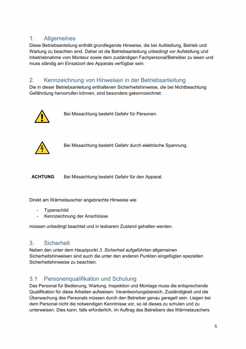
1. Allgemeines
Diese Betriebsanleitung enthält grundlegende Hinweise, die bei Aufstellung, Betrieb und Wartung zu beachten sind. Daher ist die Betriebsanleitung unbedingt vor Aufstellung und Inbetriebnahme vom Monteur sowie dem zuständigen Fachpersonal/Betreiber zu lesen und muss ständig am Einsatzort des Apparats verfügbar sein.
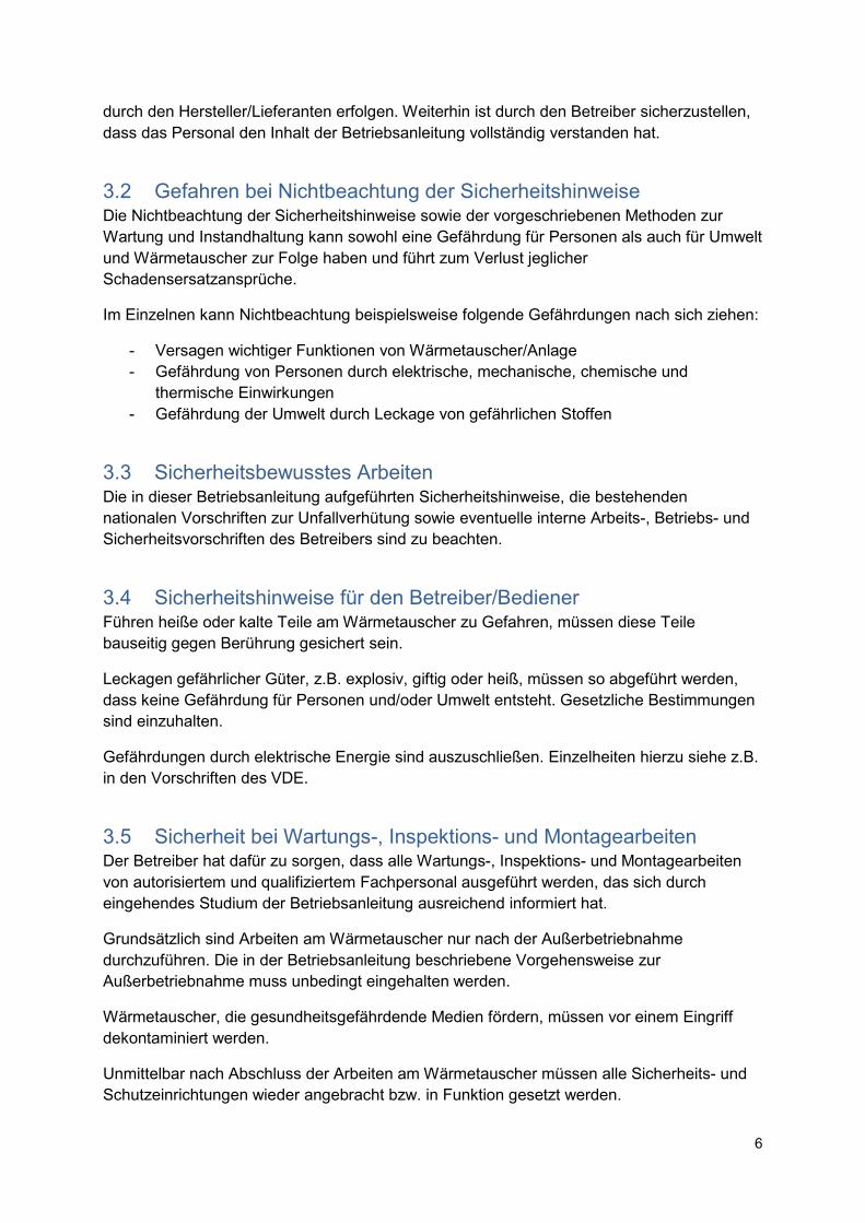
2. Kennzeichnung von Hinweisen in der Betriebsanleitung Die in dieser Betriebsanleitung enthaltenen Sicherheitshinweise, die bei Nichtbeachtung Gefährdung hervorrufen können, sind besonders gekennzeichnet:
Bei Missachtung besteht Gefahr für Personen.
Bei Missachtung besteht Gefahr durch elektrische Spannung.
ACHTUNG
Bei Missachtung besteht Gefahr für den Apparat.
Direkt am Wärmetauscher angebrachte Hinweise wie
- Typenschild - Kennzeichnung der Anschlüsse
müssen unbedingt beachtet und in lesbarem Zustand gehalten werden.
3. Sicherheit Neben den unter dem Hauptpunkt 3. Sicherheit aufgeführten allgemeinen Sicherheitshinweisen sind auch die unter den anderen Punkten eingefügten speziellen Sicherheitshinweise zu beachten.
3.1 Personenqualifikation und Schulung Das Personal für Bedienung, Wartung, Inspektion und Montage muss die entsprechende Qualifikation für diese Arbeiten aufweisen. Verantwortungsbereich, Zuständigkeit und die Überwachung des Personals müssen durch den Betreiber genau geregelt sein. Liegen bei dem Personal nicht die notwendigen Kenntnisse vor, so ist dieses zu schulen und zu unterweisen. Dies kann, falls erforderlich, im Auftrag des Betreibers des Wärmetauschers
6
durch den Hersteller/Lieferanten erfolgen. Weiterhin ist durch den Betreiber sicherzustellen, dass das Personal den Inhalt der Betriebsanleitung vollständig verstanden hat.
3.2 Gefahren bei Nichtbeachtung der Sicherheitshinweise Die Nichtbeachtung der Sicherheitshinweise sowie der vorgeschriebenen Methoden zur Wartung und Instandhaltung kann sowohl eine Gefährdung für Personen als auch für Umwelt und Wärmetauscher zur Folge haben und führt zum Verlust jeglicher Schadensersatzansprüche.
Im Einzelnen kann Nichtbeachtung beispielsweise folgende Gefährdungen nach sich ziehen:
- Versagen wichtiger Funktionen von Wärmetauscher/Anlage - Gefährdung von Personen durch elektrische, mechanische, chemische und
thermische Einwirkungen - Gefährdung der Umwelt durch Leckage von gefährlichen Stoffen
3.3 Sicherheitsbewusstes Arbeiten Die in dieser Betriebsanleitung aufgeführten Sicherheitshinweise, die bestehenden nationalen Vorschriften zur Unfallverhütung sowie eventuelle interne Arbeits-, Betriebs- und Sicherheitsvorschriften des Betreibers sind zu beachten.
3.4 Sicherheitshinweise für den Betreiber/Bediener Führen heiße oder kalte Teile am Wärmetauscher zu Gefahren, müssen diese Teile bauseitig gegen Berührung gesichert sein.
Leckagen gefährlicher Güter, z.B. explosiv, giftig oder heiß, müssen so abgeführt werden, dass keine Gefährdung für Personen und/oder Umwelt entsteht. Gesetzliche Bestimmungen sind einzuhalten.
Gefährdungen durch elektrische Energie sind auszuschließen. Einzelheiten hierzu siehe z.B. in den Vorschriften des VDE.
3.5 Sicherheit bei Wartungs-, Inspektions- und Montagearbeiten Der Betreiber hat dafür zu sorgen, dass alle Wartungs-, Inspektions- und Montagearbeiten von autorisiertem und qualifiziertem Fachpersonal ausgeführt werden, das sich durch eingehendes Studium der Betriebsanleitung ausreichend informiert hat.
Grundsätzlich sind Arbeiten am Wärmetauscher nur nach der Außerbetriebnahme durchzuführen. Die in der Betriebsanleitung beschriebene Vorgehensweise zur Außerbetriebnahme muss unbedingt eingehalten werden.
Wärmetauscher, die gesundheitsgefährdende Medien fördern, müssen vor einem Eingriff dekontaminiert werden.
Unmittelbar nach Abschluss der Arbeiten am Wärmetauscher müssen alle Sicherheits- und Schutzeinrichtungen wieder angebracht bzw. in Funktion gesetzt werden.
7
Vor Wiederinbetriebnahme sind die im Abschnitt 8. Inbetriebnahme aufgeführten Punkte zu beachten.
3.6 Eigenmächtiger Umbau und Ersatzteilherstellung Umbau oder Veränderungen des Wärmetauschers sind nur nach Absprache mit dem Hersteller zulässig.
Originalersatzteile und vom Hersteller autorisiertes Zubehör dienen der Sicherheit. Die Verwendung anderer Teile schließt die Haftung für die daraus entstehenden Folgen aus.
3.7 Unzulässige Betriebsweisen Die Betriebssicherheit des gelieferten Wärmetauschers ist nur bei bestimmungsgemäßer Verwendung gewährleistet.
Die angegebenen Grenzwerte, die in der Auftragsbestätigung, im Prospektblatt oder in Datenblättern aufgeführt sind, dürfen auf keinen Fall überschritten werden.
8
4. Beschreibung Wärmetauscher sind Apparate, die Wärme entlang eines Temperaturgefälles zwischen zwei oder mehr Stoffströmen übertragen. Die beteiligten Medien können flüssig oder gasförmig sein. Eine gezielte Änderung des Aggregatzustands der Medien und/oder sonstiger physikalischer Eigenschaften kann mit Wärmetauschern herbeigeführt werden.
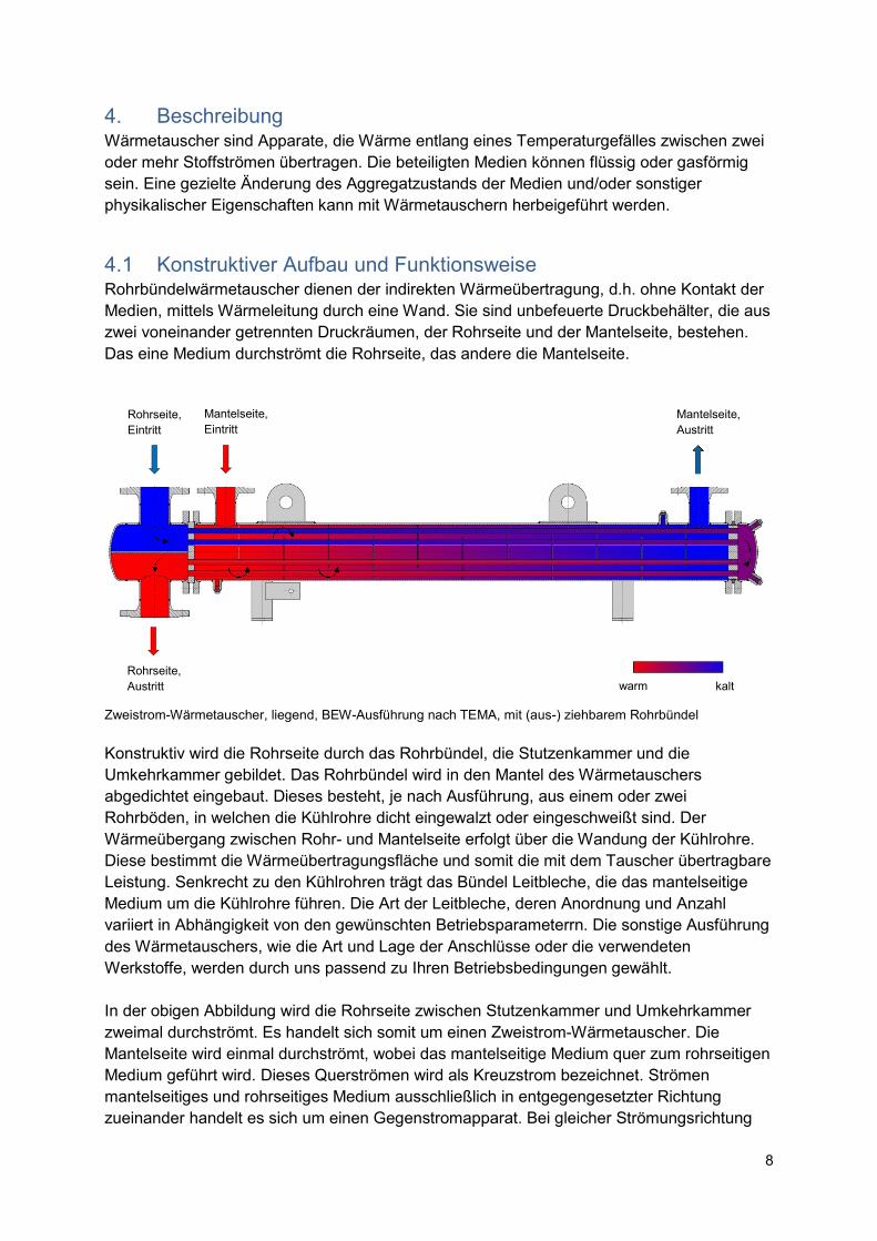
4.1 Konstruktiver Aufbau und Funktionsweise Rohrbündelwärmetauscher dienen der indirekten Wärmeübertragung, d.h. ohne Kontakt der Medien, mittels Wärmeleitung durch eine Wand. Sie sind unbefeuerte Druckbehälter, die aus zwei voneinander getrennten Druckräumen, der Rohrseite und der Mantelseite, bestehen. Das eine Medium durchströmt die Rohrseite, das andere die Mantelseite.
Zweistrom-Wärmetauscher, liegend, BEW-Ausführung nach TEMA, mit (aus-) ziehbarem Rohrbündel
Konstruktiv wird die Rohrseite durch das Rohrbündel, die Stutzenkammer und die Umkehrkammer gebildet. Das Rohrbündel wird in den Mantel des Wärmetauschers abgedichtet eingebaut. Dieses besteht, je nach Ausführung, aus einem oder zwei Rohrböden, in welchen die Kühlrohre dicht eingewalzt oder eingeschweißt sind. Der Wärmeübergang zwischen Rohr- und Mantelseite erfolgt über die Wandung der Kühlrohre. Diese bestimmt die Wärmeübertragungsfläche und somit die mit dem Tauscher übertragbare Leistung. Senkrecht zu den Kühlrohren trägt das Bündel Leitbleche, die das mantelseitige Medium um die Kühlrohre führen. Die Art der Leitbleche, deren Anordnung und Anzahl variiert in Abhängigkeit von den gewünschten Betriebsparameterrn. Die sonstige Ausführung des Wärmetauschers, wie die Art und Lage der Anschlüsse oder die verwendeten Werkstoffe, werden durch uns passend zu Ihren Betriebsbedingungen gewählt.
In der obigen Abbildung wird die Rohrseite zwischen Stutzenkammer und Umkehrkammer zweimal durchströmt. Es handelt sich somit um einen Zweistrom-Wärmetauscher. Die Mantelseite wird einmal durchströmt, wobei das mantelseitige Medium quer zum rohrseitigen Medium geführt wird. Dieses Querströmen wird als Kreuzstrom bezeichnet. Strömen mantelseitiges und rohrseitiges Medium ausschließlich in entgegengesetzter Richtung zueinander handelt es sich um einen Gegenstromapparat. Bei gleicher Strömungsrichtung
Rohrseite, Eintritt
Mantelseite, Eintritt
Rohrseite, Austritt
Mantelseite, Austritt
warm kalt
9
handelt es sich um einen Gleichstromapparat. In der obigen Abbildung strömt das rohrseitige Medium zunächst im Gleichstrom von der Stutzen- zur Umkehrkammer und anschließend im Gegenstrom bis zum Austritt.
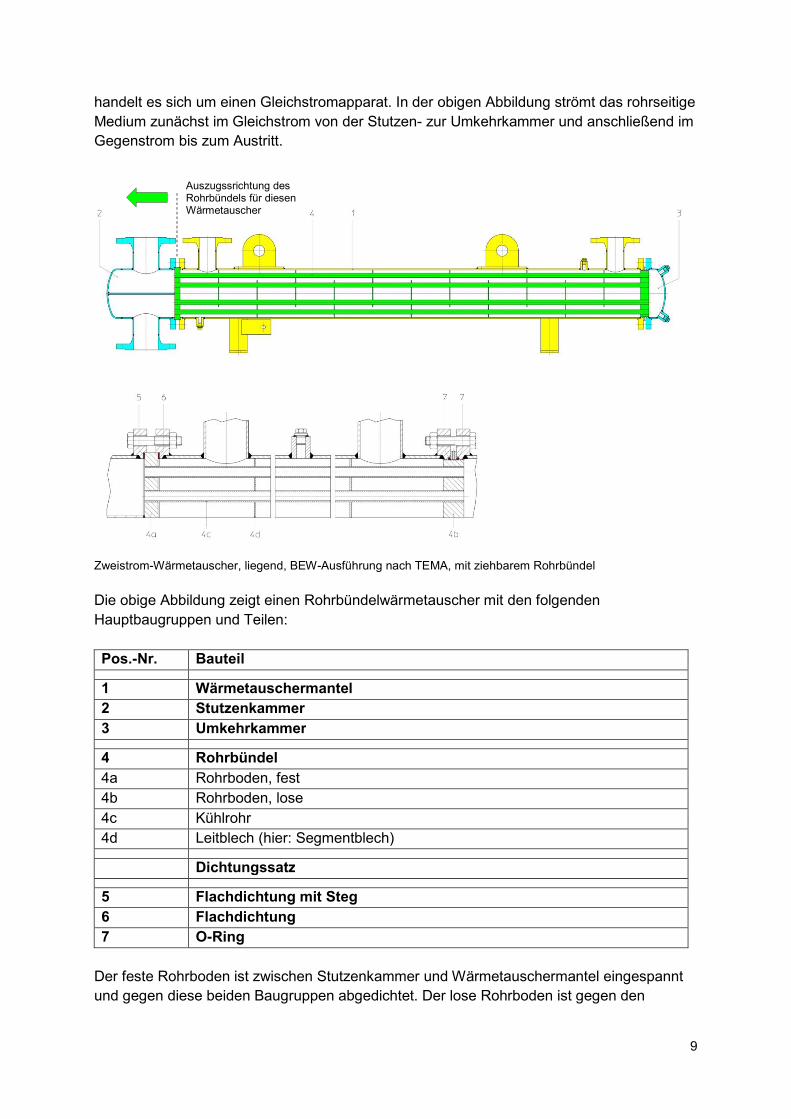
Zweistrom-Wärmetauscher, liegend, BEW-Ausführung nach TEMA, mit ziehbarem Rohrbündel Die obige Abbildung zeigt einen Rohrbündelwärmetauscher mit den folgenden Hauptbaugruppen und Teilen:
Pos.-Nr. Bauteil
1 Wärmetauschermantel
2 Stutzenkammer
3 Umkehrkammer
4 Rohrbündel
4a Rohrboden, fest
4b Rohrboden, lose
4c Kühlrohr
4d Leitblech (hier: Segmentblech)
Dichtungssatz
5 Flachdichtung mit Steg
6 Flachdichtung
7 O-Ring
Der feste Rohrboden ist zwischen Stutzenkammer und Wärmetauschermantel eingespannt und gegen diese beiden Baugruppen abgedichtet. Der lose Rohrboden ist gegen den
Auszugssrichtung des Rohrbündels für diesen Wärmetauscher
10
Wärmetauschermantel und die Umkehrkammer beweglich abgedichtet, um wärmebedingte Längenänderungen des Rohrbündels ausgleichen zu können.
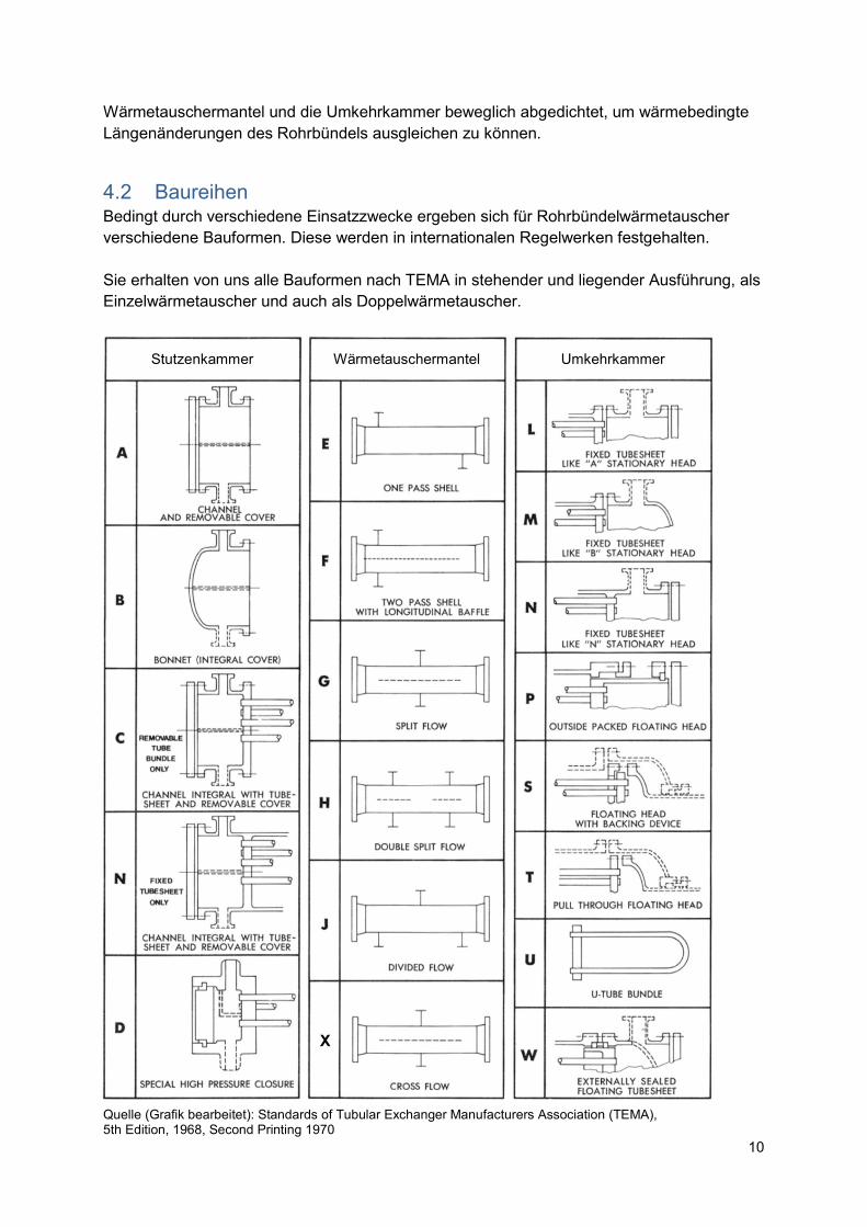
4.2 Baureihen Bedingt durch verschiedene Einsatzzwecke ergeben sich für Rohrbündelwärmetauscher verschiedene Bauformen. Diese werden in internationalen Regelwerken festgehalten. Sie erhalten von uns alle Bauformen nach TEMA in stehender und liegender Ausführung, als Einzelwärmetauscher und auch als Doppelwärmetauscher.
Quelle (Grafik bearbeitet): Standards of Tubular Exchanger Manufacturers Association (TEMA), 5th Edition, 1968, Second Printing 1970
Stutzenkammer Wärmetauschermantel Umkehrkammer
11
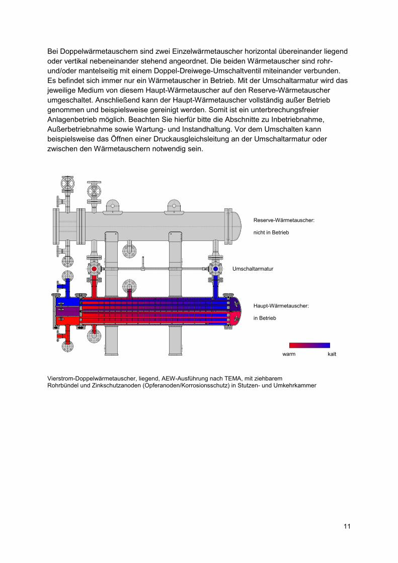
Bei Doppelwärmetauschern sind zwei Einzelwärmetauscher horizontal übereinander liegend oder vertikal nebeneinander stehend angeordnet. Die beiden Wärmetauscher sind rohr- und/oder mantelseitig mit einem Doppel-Dreiwege-Umschaltventil miteinander verbunden. Es befindet sich immer nur ein Wärmetauscher in Betrieb. Mit der Umschaltarmatur wird das jeweilige Medium von diesem Haupt-Wärmetauscher auf den Reserve-Wärmetauscher umgeschaltet. Anschließend kann der Haupt-Wärmetauscher vollständig außer Betrieb genommen und beispielsweise gereinigt werden. Somit ist ein unterbrechungsfreier Anlagenbetrieb möglich. Beachten Sie hierfür bitte die Abschnitte zu Inbetriebnahme, Außerbetriebnahme sowie Wartung- und Instandhaltung. Vor dem Umschalten kann beispielsweise das Öffnen einer Druckausgleichsleitung an der Umschaltarmatur oder zwischen den Wärmetauschern notwendig sein.
Vierstrom-Doppelwärmetauscher, liegend, AEW-Ausführung nach TEMA, mit ziehbarem Rohrbündel und Zinkschutzanoden (Opferanoden/Korrosionsschutz) in Stutzen- und Umkehrkammer
warm kalt
Reserve-Wärmetauscher: nicht in Betrieb
Umschaltarmatur
Haupt-Wärmetauscher: in Betrieb
12
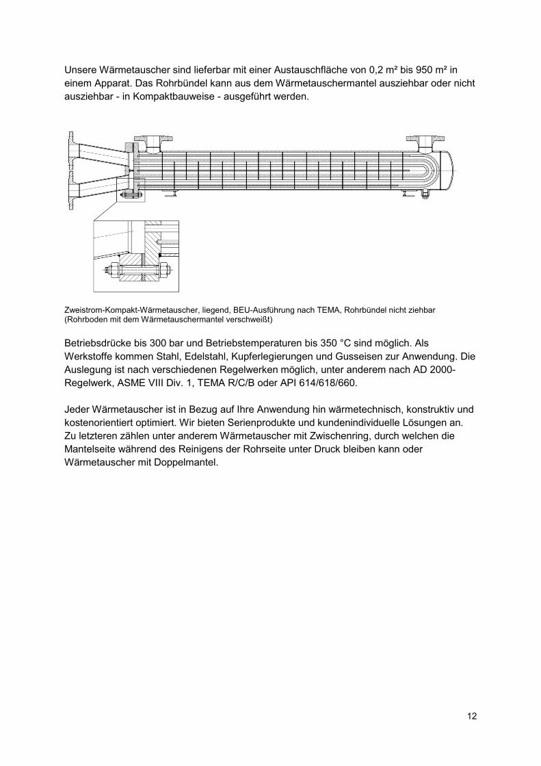
Unsere Wärmetauscher sind lieferbar mit einer Austauschfläche von 0,2 m² bis 950 m² in einem Apparat. Das Rohrbündel kann aus dem Wärmetauschermantel ausziehbar oder nicht ausziehbar - in Kompaktbauweise - ausgeführt werden.
Zweistrom-Kompakt-Wärmetauscher, liegend, BEU-Ausführung nach TEMA, Rohrbündel nicht ziehbar (Rohrboden mit dem Wärmetauschermantel verschweißt)
Betriebsdrücke bis 300 bar und Betriebstemperaturen bis 350 °C sind möglich. Als Werkstoffe kommen Stahl, Edelstahl, Kupferlegierungen und Gusseisen zur Anwendung. Die Auslegung ist nach verschiedenen Regelwerken möglich, unter anderem nach AD 2000-Regelwerk, ASME VIII Div. 1, TEMA R/C/B oder API 614/618/660. Jeder Wärmetauscher ist in Bezug auf Ihre Anwendung hin wärmetechnisch, konstruktiv und kostenorientiert optimiert. Wir bieten Serienprodukte und kundenindividuelle Lösungen an. Zu letzteren zählen unter anderem Wärmetauscher mit Zwischenring, durch welchen die Mantelseite während des Reinigens der Rohrseite unter Druck bleiben kann oder Wärmetauscher mit Doppelmantel.
13
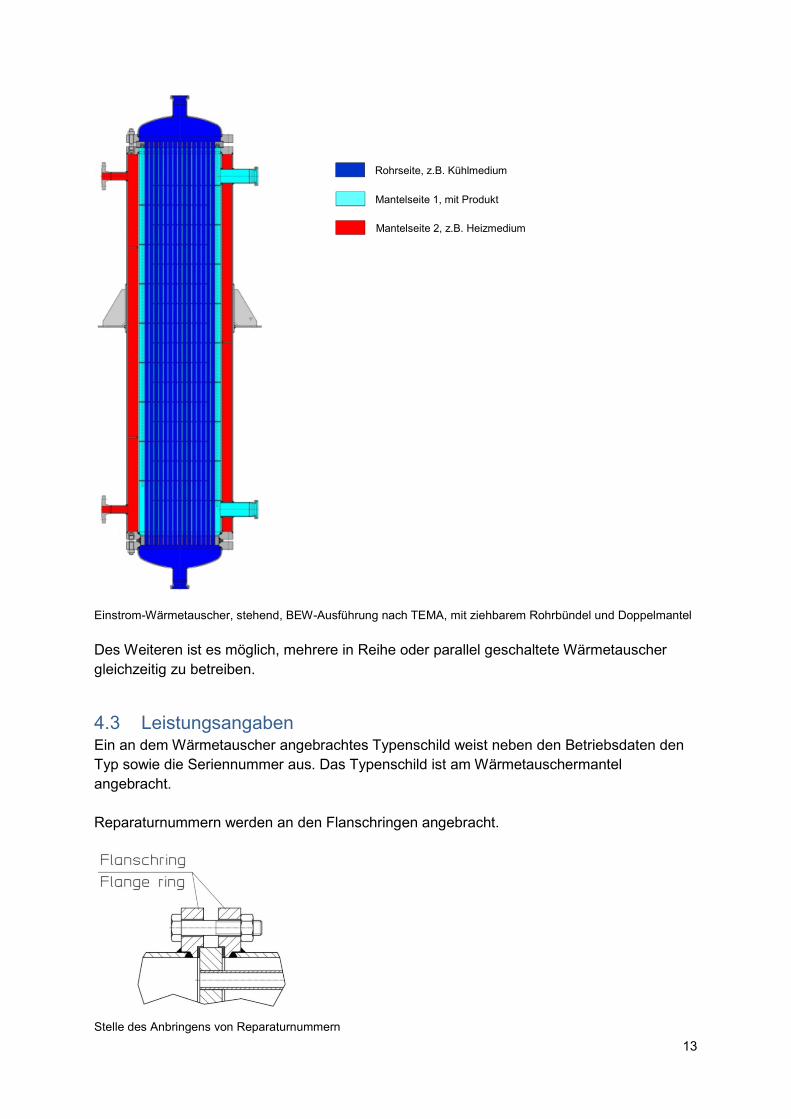
Einstrom-Wärmetauscher, stehend, BEW-Ausführung nach TEMA, mit ziehbarem Rohrbündel und Doppelmantel Des Weiteren ist es möglich, mehrere in Reihe oder parallel geschaltete Wärmetauscher gleichzeitig zu betreiben.
4.3 Leistungsangaben Ein an dem Wärmetauscher angebrachtes Typenschild weist neben den Betriebsdaten den Typ sowie die Seriennummer aus. Das Typenschild ist am Wärmetauschermantel angebracht. Reparaturnummern werden an den Flanschringen angebracht.
Stelle des Anbringens von Reparaturnummern
Rohrseite, z.B. Kühlmedium
Mantelseite 1, mit Produkt
Mantelseite 2, z.B. Heizmedium
14
Direkt am Wärmetauscher angebrachte Hinweise müssen unbedingt beachtet und in lesbarem Zustand gehalten werden.
Bei Rückfragen, Nachbestellungen und insbesondere bei Bestellung von Ersatzteilen
ist die Seriennummer stets anzugeben.
Die wärmetechnischen Auslegungsdaten sind bei nahezu jedem Wärmeaustauscher unterschiedlich. Falls erforderlich können diese Daten, in Form eines Datenblatts, bei uns angefordert werden.
4.4 Einsatzgebiete ACHTUNG
Der Wärmetauscher darf nur für die vom Hersteller bestätigten Einsatzgebiete betrieben werden.
5. Transport
Der Transport muss fachgerecht erfolgen. Das auf dem Typenschild angegebene Gewicht ist zu beachten.
Das Anhängen des unverpackten Wärmetauschers an Krananalagen erfolgt mittels um das Mantelrohr gelegter Transportschlingen oder durch das Anhängen an die dafür vorgesehenen Tragösen am Wärmetauschermantel.
Zusätzliche, beispielsweise an Stutzenkammer und/oder Umkehrkammer, angebrachte Tragösen oder Ringschrauben dienen nicht dem Heben des gesamten Wärmetauschers sondern nur dem Heben der einzelnen Baugruppe im demontierten Zustand !
ACHTUNG
Wärmetauscher müssen gegen korrosive Einflüsse, Stöße und Schläge ausreichend geschützt sein, um Undichtigkeit und Bauteilversagen zu vermeiden. Zusätzlich können Beschädigungen des Mantelrohrs zu Schwierigkeiten beim Ziehen des Rohrbündels führen.
15
ACHTUNG
Ein- und Austritte des Wärmetauschers sind mit Schutzstopfen zu versehen. Diese Maßnahme ist erforderlich um den Innenraum vor Korrosion zu schützen und den Austritt von Restflüssigkeit bzw. das Eindringen von Fremdkörpern zu verhindern.
6. Lagerung Die Lagerung der Wärmetauscher soll bei trockenen Verhältnissen erfolgen. Die ein- und austrittseitig angebrachten Schutzstopfen sollten bis zur Verwendung des Wärmetrauschers an Ort und Stelle verbleiben. Bei mehr als sechsmonatiger Lagerung der Wärmetauscher vor Verwendung sollten Korrosionsschutzmaßnahmen für die metallisch blanken Teile der Wärmetauscher getroffen werden.
7. Aufstellung Vor dem Einbau ist der Wärmetauscher auf Transportschäden und Verunreinigungen zu überprüfen. Der Aufstellungsort sollte so gewählt werden, dass der Wärmetauscher leicht zugänglich ist, insbesondere Entlüftungs- und Entleerungsanschlüsse. Für Inspektions- und Wartungsarbeiten ist genügend Raum vorzusehen, insbesondere für das Ausbringen des gesamten Wärmetauschers oder das Ziehen des Rohrbündels vor Ort. Bitte beachten Sie die Ausziehrichtung und die Ausziehlänge des Rohrbündels.
Der Wärmetauscher ist auf einem waagerechten, ebenen und festen Untergrund zu montieren. Bei unebenem Boden sind die Füße des Wärmetauschers durch Unterlagen, Zementausguss oder gleichwertiges abzustützen.
ACHTUNG
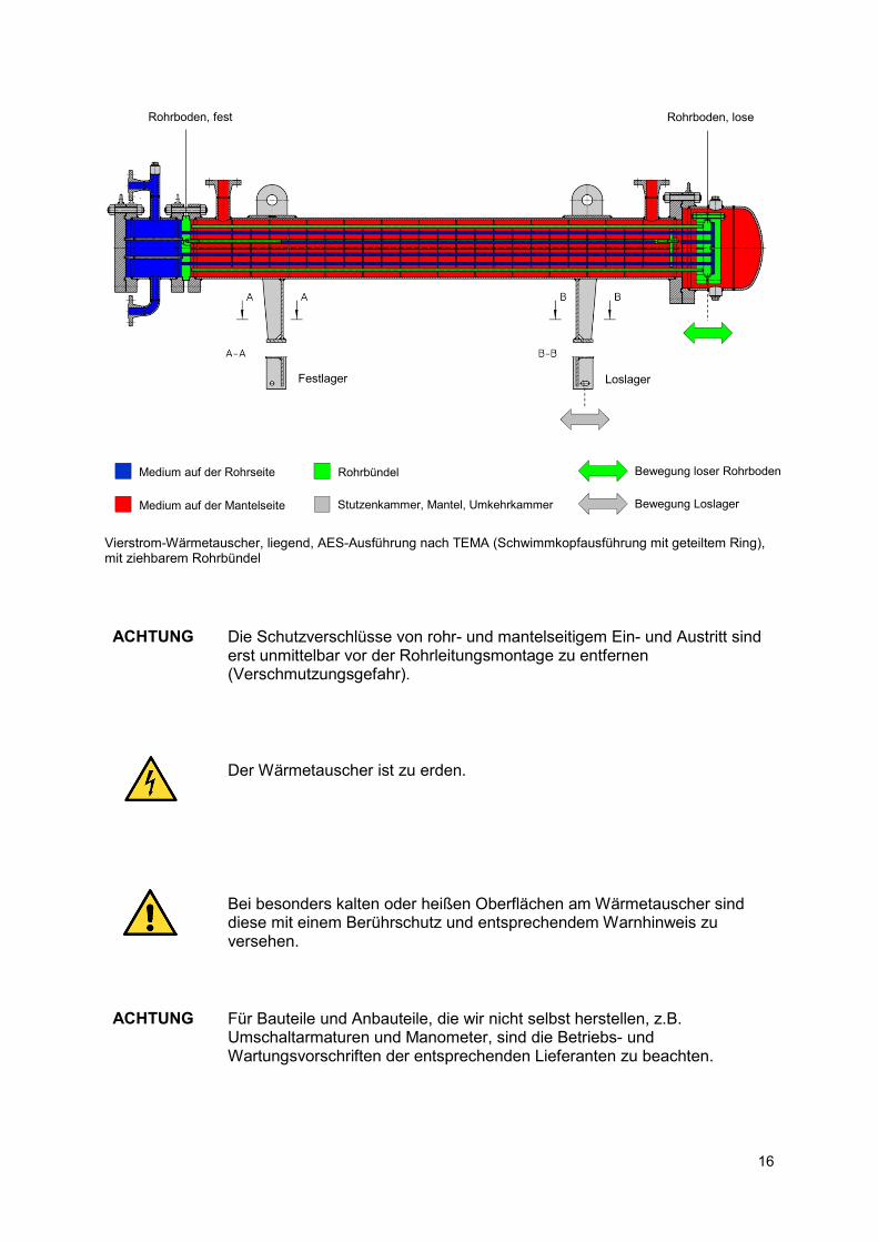
Jeder Wärmetauscher dehnt sich während des Anfahrens durch die Erwärmung des Materials aus und zieht sich beim Abfahren mit dem Abkühlen wieder zusammen. Das Rohrbündel ist im Wärmetauschermantel so montiert, dass die Längenausdehnung des Rohrbündels im Wärmetauscher erfolgt. Unabhängig davon erfolgt die Ausdehnung des Wärmetauschermantels. Die Füße des Apparats sind deswegen, bei liegenden Bauformen, auf der einen Seite als Festlager und auf der anderen als Loslager ausgeführt.
16
Vierstrom-Wärmetauscher, liegend, AES-Ausführung nach TEMA (Schwimmkopfausführung mit geteiltem Ring), mit ziehbarem Rohrbündel ACHTUNG
Die Schutzverschlüsse von rohr- und mantelseitigem Ein- und Austritt sind erst unmittelbar vor der Rohrleitungsmontage zu entfernen (Verschmutzungsgefahr).
Der Wärmetauscher ist zu erden.
Bei besonders kalten oder heißen Oberflächen am Wärmetauscher sind diese mit einem Berührschutz und entsprechendem Warnhinweis zu versehen.
ACHTUNG
Für Bauteile und Anbauteile, die wir nicht selbst herstellen, z.B. Umschaltarmaturen und Manometer, sind die Betriebs- und Wartungsvorschriften der entsprechenden Lieferanten zu beachten.
Rohrboden, fest
Rohrboden, lose
Medium auf der Rohrseite
Medium auf der Mantelseite
Rohrbündel
Stutzenkammer, Mantel, Umkehrkammer
Festlager
Loslager
Bewegung loser Rohrboden
Bewegung Loslager
17
7.1 Rohrleitungen ACHTUNG
Rohrleitungen sind vor dem Anschluss zu reinigen. Sie müssen frei von Zunder, Schweißrückständen, Sand, Spänen und Rostansätzen sein. Der Anschluss muss spannungsfrei erfolgen.
ACHTUNG
Die Rohrleitungen müssen ausreichend dimensioniert sein. Sie dürfen nicht kleiner als die Nennweite der Wärmetauscheranschlüsse gewählt werden. Im Rohrleitungsverlauf erforderliche Biegungen sollten mit möglichst großem Radius ausgeführt werden.
8. Inbetriebnahme ACHTUNG
Es sind alle Konservierungen und Verschlüsse zu entfernen, die für den Transport und die Lagerung des Wärmetauschers an- oder eingebracht wurden.
ACHTUNG
Vor dem Anschließen an das Rohrleitungssystem ist die korrekte Strömungsführung am Wärmetauscher anhand der auftragsspezifischen Dokumentation zu überprüfen. Diese Zuordnung von Eintritt und Austritt zu den richtigen Stutzen kann beispielsweise mit Hilfe unserer Ansichtszeichnung (Maßblatt) erfolgen.
Zusätzlich zu den Anschlüssen für Eintritt und Austritt hat der Wärmetauscher Vorrichtungen für das Entlüften oder Entleeren. Standardmäßig werden hierfür Muffen mit Verschlussschraube vorgesehen, alternativ geflanschte Ausführungen. Die Entlüftung befindet sich am höchsten Punkt des jeweiligen Druckraums, die Entleerung am tiefsten. Sind solche separaten Entlüftungen und/oder Entleerungen nicht vorhanden, dann erfolgt die Entlüftung und/oder Entleerung über den Austritt des jeweiligen Mediums im Betrieb. ACHTUNG
Für das Anschließen des Wärmetauschers an das Rohrleitungssystem sind stets neue Dichtungen zu verwenden.
Wärmetauscher sind möglichst gleichmäßig anzufahren. Druckstöße sind zu vermeiden. Die vereinbarten Grenzwerte für den Betrieb sind einzuhalten.
18
Nach dem Anschließen des Wärmetauschers an das Rohrleitungssystem sind die einzelnen Schritte für die Inbetriebnahme:
- für Wärmetauscher mit Umschaltarmatur:
o sicherstellen, dass die Umschaltung auf den richtigen Wärmetauscher
umgeschaltet ist o die Druckausgleichsleitung an der Umschaltung oder zwischen den
Wärmetauschern ist zu schließen, so dass das Medium nur in den für den Betrieb vorgesehenen Tauscher strömt
o die Betriebsanleitung des Lieferanten der Umschaltarmatur ist zu beachten
- für weitere, am Wärmetauscher angebrachte Armaturen, wie Manometer, Sicherheitsventile oder Berstscheiben, ist die Betriebsanleitung des jeweiligen Lieferanten zu beachten
- Sicherstellen, dass alle Entlüftungen und Entleerungen geschlossen sind - Öffnen aller Austritte am Wärmetauscher - Öffnen des Eintritts des sich im Betrieb erwärmenden Mediums (Kühlmedium) - Öffnen des Eintritts des sich im Betrieb abkühlenden Mediums (Heizmedium) - Entlüften der Seite des Kühlmediums - Entlüften der Seite des Heizmediums - Einregulieren von Kühl- und Heizmedium bis zum gewünschten Betriebspunkt
Für weitere Druckräume am Wärmetauscher, zum Beispiel an Wärmetauschern mit Doppelmantel, ist analog vorzugehen. Beim Anfahren mit zähen Medien können vorübergehend hohe Druckverluste entstehen. Deshalb ist es in manchen Fällen ratsam, eine Bypass-Regulierung für den Kaltstart vorzusehen. ACHTUNG
Durch die teilweise hohen Temperaturänderungen beim Anfahren und Setzung können an den äußeren Dichtverbindungen, zum Beispiel an Rohrleitungsanschlüssen und Flanschringen, kleine Leckagen auftreten. Diese können durch leichtes Nachziehen der Schrauben beseitigt werden.
Längere Stillstandzeiten sind wegen der dann erhöhten Korrosionsgefahr zu vermeiden. Für längeren Stillstand ist der Wärmetauscher ggf. zu spülen und in jedem Fall vollständig zu entleeren.
8.1 Umschalten von Doppelwärmetauschern nach der Inbetriebnahme Die einzelnen Schritte für das Umschalten eines Doppelwärmetauschers mit Umschaltung auf der Mantelseite und ohne Umschaltung auf der Rohrseite sind nachfolgend wiedergegeben. Dabei wird davon ausgegangen, dass das Kühlmedium auf der Rohrseite und das Heizmedium auf der Mantelseite strömt:
19
- Sicherstellen, dass die Entlüftungen und Entleerungen des Reserve-Wärmetauschers geschlossen sind
- Öffnen der Austritte des Reserve-Wärmetauschers - Öffnen des Eintritts des Kühlmediums am Reserve-Wärmetauscher - Öffnen der Druckausgleichsleitung an der Umschaltarmatur oder zwischen den
beiden Mantelseiten; die Betriebsanleitung der Umschaltarmatur ist zu beachten - Umschalten des mantelseitigen Heizmediums - Schließen der Druckausgleichsleitung - Schließen des Eintritts des Kühlmediums am stillgesetzten Wärmetauscher - Schließen des Austritts des Kühlmediums am stillgesetzten Wärmetauscher - Entlüften der Rohrseite des Reserve-Wärmetauschers (Kühlmedium) - Entlüften der Mantelseite des Reserve-Wärmetauschers (Heizmedium) - Einregulieren von Kühl- und Heizmedium bis zum gewünschten Betriebspunkt - Außerbetriebnahme des stillgesetzten Wärmetauschers
9. Außerbetriebnahme ACHTUNG
Bei längeren Stillstandsperioden ohne Demontage, für die Inspektion oder bei Frostgefahr ist der Wärmetauscher zu entleeren bzw. gegen Einfrieren zu sichern.
Für das Entleeren den Wärmetauscher zunächst von der Anlage trennen, zum Beispiel durch das Schließen von Absperrventilen und ihn anschließend druckentlasten. Danach zuerst die Entlüftung und anschließend die Entleerung des jeweiligen Druckraums öffnen. Austretendes Medium entsprechend auffangen. Die Füllmengen des Wärmetauschers sind auf dem Typenschild angegeben. Der Wärmetauscher ist vollständig zu entleeren.
Enthält der Wärmetauscher Restmengen gefährlicher Substanzen, z.B. giftig oder ätzend, dann muss die entsprechende Kennzeichnung für die Überholung, die sichere Lagerung und Wiederinbetriebnahme vorgenommen werden. Die Kennzeichnung muss nach den entsprechenden Vorschriften erfolgen.
Für die Einlagerung ist der Wärmetauscher entsprechend zu verschließen und zu konservieren.
20
10. Wartung und Instandhaltung Regelmäßige Wartungsarbeiten sind unerlässlich für den sicheren Betrieb von Anlagen. Umfang und Intervalle müssen den Erfordernissen vor Ort angepasst sein.
Die erste Überprüfung muss direkt nach der Inbetriebnahme erfolgen. Das sich anschließende Wartungsintervall sollte zunächst höchstens eine Woche betragen. Wenn sich sicher gezeigt hat, dass es zu keinen Veränderungen im Betriebsverhalten des Wärmetauschers kommt, kann das Wartungsintervall verlängert werden. Die Länge des Wartungsintervalls ist vom Betreiber festzulegen. Sichtkontrollen zu Schichtbeginn und notwendige Reinigungsarbeiten dürfen in keinem Fall entfallen.
Insbesondere bei längeren Stillstandzeiten kann es zum Setzen an Dichtungen kommen. Ein leichtes Nachziehen ist dann an diesen Stellen notwendig.
Wenn die Mengenströme fest eingestellt sind, dann ist die Betriebsüberwachung mit Hilfe von Temperatur- und Druckmessung am Eintritt und am Austritt von Rohr- und Mantelseite möglich. Eine Veränderung der Temperatur- oder Druckdifferenz zwischen Eintritt und Austritt lässt einen Rückschluss darauf zu, ob der Wärmetauscher verschmutzt ist oder entlüftet werden muss.
Wir empfehlen die Dokumentation von Art und Umfang der Wartung sowie der relevanten Messwerte. Eine Veränderung der Betriebsdaten lässt sich dadurch am schnellsten erkennen. Eine regelmäßige Überprüfung und Reinigung von Filtern am Eintritt oder davor und von sonstigen im System angebrachten Schmutzabscheidern ist unerlässlich. Die regelmäßige Reinigung des Wärmetauschers gewährleistet einen effizienten Wärmeübergang und eine lange, störungsfreie Betriebszeit. Aufgrund der vielfältigen Bauformen von Wärmetauschern bitten wir Sie sich für die genaue Art und Weise der Reinigung mit uns in Verbindung zu setzen. ACHTUNG
Sollte aus irgendeinem Grund ein Öffnen des Wärmetauschers erforderlich sein, so ist darauf zu achten, dass für die Wiederinbetriebnahme neue und identische Dichtungen hinsichtlich Geometrie und Werkstoff verwendet werden.
ACHTUNG
Wir empfehlen Reparaturen im Herstellerwerk durchführen zu lassen.
Bitte beachten Sie, dass während der Garantiezeit am Wärmetauscher selbst durchgeführte Arbeiten zum Erlöschen der Garantie führen. Wir übernehmen keine Haftung für direkt oder indirekt durch Arbeiten am Wärmetauscher herbeigeführte Schäden, beispielsweise am Wärmetauscher selbst, an verbundenen Anlagenteilen, Personen oder Umwelt.
21
10.1 Reinigen des Wärmetauschers Steigen Druckverlust und Temperaturen über das Normalmaß an, so kann dies durch eine Verschmutzung des Wärmeaustauschers begründet sein, sofern das Betriebsverhalten zuvor normal war.
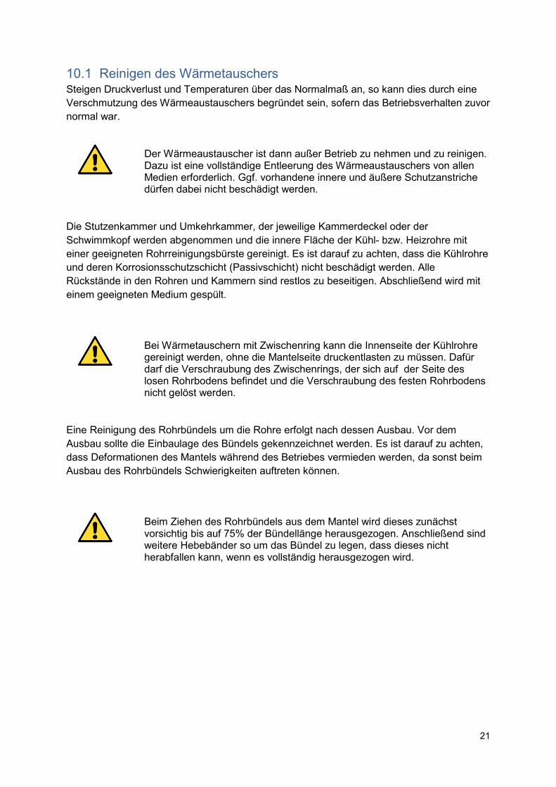
Der Wärmeaustauscher ist dann außer Betrieb zu nehmen und zu reinigen. Dazu ist eine vollständige Entleerung des Wärmeaustauschers von allen Medien erforderlich. Ggf. vorhandene innere und äußere Schutzanstriche dürfen dabei nicht beschädigt werden.
Die Stutzenkammer und Umkehrkammer, der jeweilige Kammerdeckel oder der Schwimmkopf werden abgenommen und die innere Fläche der Kühl- bzw. Heizrohre mit einer geeigneten Rohrreinigungsbürste gereinigt. Es ist darauf zu achten, dass die Kühlrohre und deren Korrosionsschutzschicht (Passivschicht) nicht beschädigt werden. Alle Rückstände in den Rohren und Kammern sind restlos zu beseitigen. Abschließend wird mit einem geeigneten Medium gespült.
Bei Wärmetauschern mit Zwischenring kann die Innenseite der Kühlrohre gereinigt werden, ohne die Mantelseite druckentlasten zu müssen. Dafür darf die Verschraubung des Zwischenrings, der sich auf der Seite des losen Rohrbodens befindet und die Verschraubung des festen Rohrbodens nicht gelöst werden.
Eine Reinigung des Rohrbündels um die Rohre erfolgt nach dessen Ausbau. Vor dem Ausbau sollte die Einbaulage des Bündels gekennzeichnet werden. Es ist darauf zu achten, dass Deformationen des Mantels während des Betriebes vermieden werden, da sonst beim Ausbau des Rohrbündels Schwierigkeiten auftreten können.
Beim Ziehen des Rohrbündels aus dem Mantel wird dieses zunächst vorsichtig bis auf 75% der Bündellänge herausgezogen. Anschließend sind weitere Hebebänder so um das Bündel zu legen, dass dieses nicht herabfallen kann, wenn es vollständig herausgezogen wird.
22
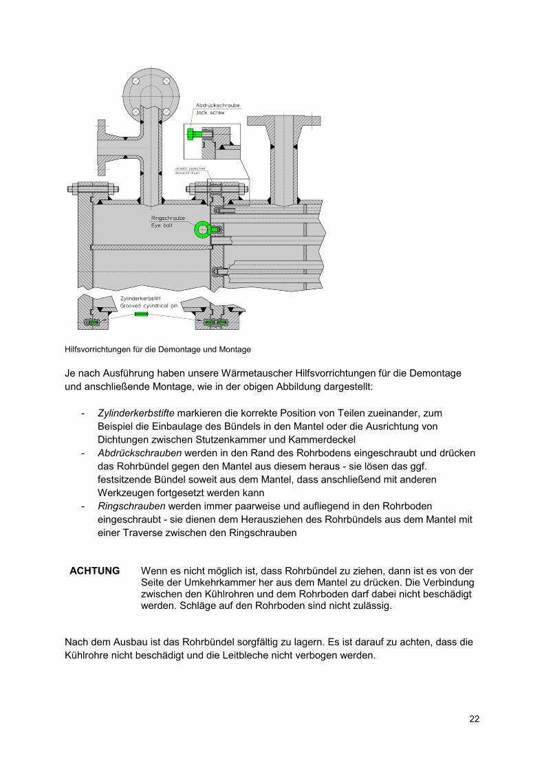
Hilfsvorrichtungen für die Demontage und Montage Je nach Ausführung haben unsere Wärmetauscher Hilfsvorrichtungen für die Demontage und anschließende Montage, wie in der obigen Abbildung dargestellt:
- Zylinderkerbstifte markieren die korrekte Position von Teilen zueinander, zum Beispiel die Einbaulage des Bündels in den Mantel oder die Ausrichtung von Dichtungen zwischen Stutzenkammer und Kammerdeckel
- Abdrückschrauben werden in den Rand des Rohrbodens eingeschraubt und drücken das Rohrbündel gegen den Mantel aus diesem heraus - sie lösen das ggf. festsitzende Bündel soweit aus dem Mantel, dass anschließend mit anderen Werkzeugen fortgesetzt werden kann
- Ringschrauben werden immer paarweise und aufliegend in den Rohrboden eingeschraubt - sie dienen dem Herausziehen des Rohrbündels aus dem Mantel mit einer Traverse zwischen den Ringschrauben
ACHTUNG
Wenn es nicht möglich ist, dass Rohrbündel zu ziehen, dann ist es von der Seite der Umkehrkammer her aus dem Mantel zu drücken. Die Verbindung zwischen den Kühlrohren und dem Rohrboden darf dabei nicht beschädigt werden. Schläge auf den Rohrboden sind nicht zulässig.
Nach dem Ausbau ist das Rohrbündel sorgfältig zu lagern. Es ist darauf zu achten, dass die Kühlrohre nicht beschädigt und die Leitbleche nicht verbogen werden.
23
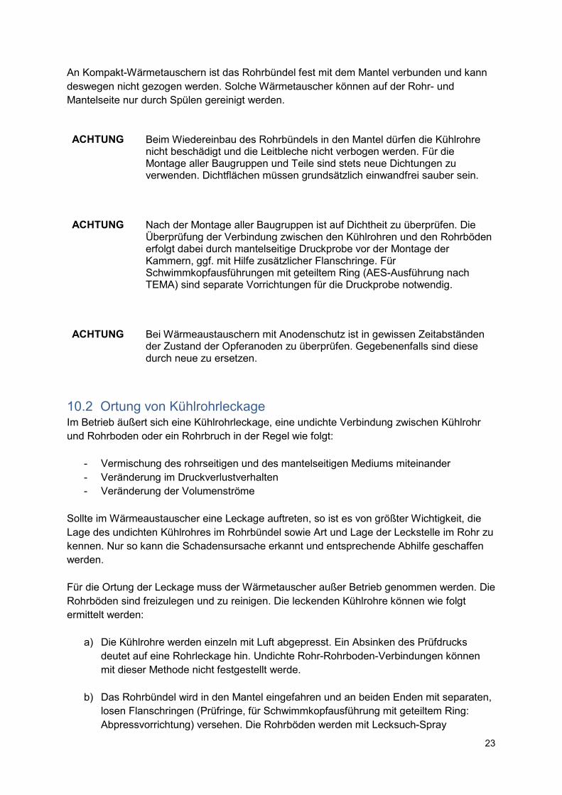
An Kompakt-Wärmetauschern ist das Rohrbündel fest mit dem Mantel verbunden und kann deswegen nicht gezogen werden. Solche Wärmetauscher können auf der Rohr- und Mantelseite nur durch Spülen gereinigt werden. ACHTUNG
Beim Wiedereinbau des Rohrbündels in den Mantel dürfen die Kühlrohre nicht beschädigt und die Leitbleche nicht verbogen werden. Für die Montage aller Baugruppen und Teile sind stets neue Dichtungen zu verwenden. Dichtflächen müssen grundsätzlich einwandfrei sauber sein.
ACHTUNG
Nach der Montage aller Baugruppen ist auf Dichtheit zu überprüfen. Die Überprüfung der Verbindung zwischen den Kühlrohren und den Rohrböden erfolgt dabei durch mantelseitige Druckprobe vor der Montage der Kammern, ggf. mit Hilfe zusätzlicher Flanschringe. Für Schwimmkopfausführungen mit geteiltem Ring (AES-Ausführung nach TEMA) sind separate Vorrichtungen für die Druckprobe notwendig.
ACHTUNG
Bei Wärmeaustauschern mit Anodenschutz ist in gewissen Zeitabständen der Zustand der Opferanoden zu überprüfen. Gegebenenfalls sind diese durch neue zu ersetzen.
10.2 Ortung von Kühlrohrleckage Im Betrieb äußert sich eine Kühlrohrleckage, eine undichte Verbindung zwischen Kühlrohr und Rohrboden oder ein Rohrbruch in der Regel wie folgt:
- Vermischung des rohrseitigen und des mantelseitigen Mediums miteinander - Veränderung im Druckverlustverhalten - Veränderung der Volumenströme
Sollte im Wärmeaustauscher eine Leckage auftreten, so ist es von größter Wichtigkeit, die Lage des undichten Kühlrohres im Rohrbündel sowie Art und Lage der Leckstelle im Rohr zu kennen. Nur so kann die Schadensursache erkannt und entsprechende Abhilfe geschaffen werden. Für die Ortung der Leckage muss der Wärmetauscher außer Betrieb genommen werden. Die Rohrböden sind freizulegen und zu reinigen. Die leckenden Kühlrohre können wie folgt ermittelt werden:
a) Die Kühlrohre werden einzeln mit Luft abgepresst. Ein Absinken des Prüfdrucks deutet auf eine Rohrleckage hin. Undichte Rohr-Rohrboden-Verbindungen können mit dieser Methode nicht festgestellt werde.
b) Das Rohrbündel wird in den Mantel eingefahren und an beiden Enden mit separaten, losen Flanschringen (Prüfringe, für Schwimmkopfausführung mit geteiltem Ring: Abpressvorrichtung) versehen. Die Rohrböden werden mit Lecksuch-Spray
24
eingesprüht und das Rohrbündel mantelseitig mit maximal 0,3 bar Luft abgepresst. Mit dieser Methode können auch undichte Rohr-Rohrboden-Verbindungen festgestellt werden.
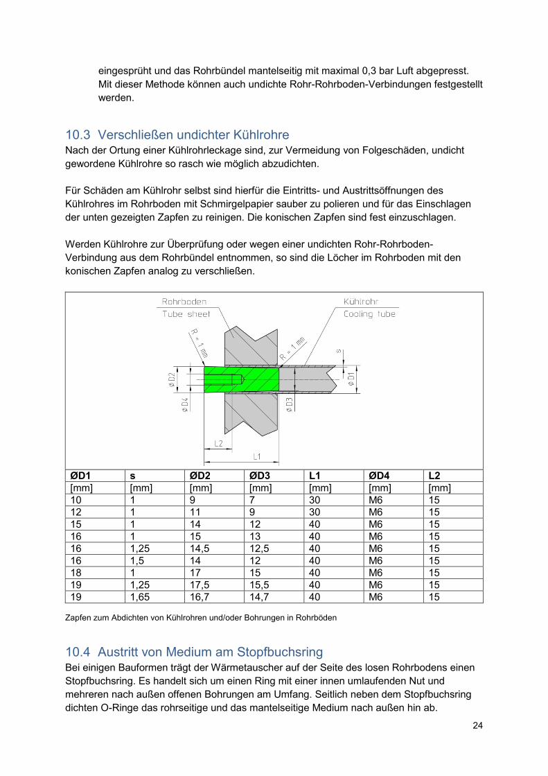
10.3 Verschließen undichter Kühlrohre Nach der Ortung einer Kühlrohrleckage sind, zur Vermeidung von Folgeschäden, undicht gewordene Kühlrohre so rasch wie möglich abzudichten. Für Schäden am Kühlrohr selbst sind hierfür die Eintritts- und Austrittsöffnungen des Kühlrohres im Rohrboden mit Schmirgelpapier sauber zu polieren und für das Einschlagen der unten gezeigten Zapfen zu reinigen. Die konischen Zapfen sind fest einzuschlagen. Werden Kühlrohre zur Überprüfung oder wegen einer undichten Rohr-Rohrboden-Verbindung aus dem Rohrbündel entnommen, so sind die Löcher im Rohrboden mit den konischen Zapfen analog zu verschließen.
ØD1 s ØD2 ØD3 L1 ØD4 L2 [mm] [mm] [mm] [mm] [mm] [mm] [mm] 10 1 9 7 30 M6 15 12 1 11 9 30 M6 15 15 1 14 12 40 M6 15 16 1 15 13 40 M6 15 16 1,25 14,5 12,5 40 M6 15 16 1,5 14 12 40 M6 15 18 1 17 15 40 M6 15 19 1,25 17,5 15,5 40 M6 15 19 1,65 16,7 14,7 40 M6 15
Zapfen zum Abdichten von Kühlrohren und/oder Bohrungen in Rohrböden
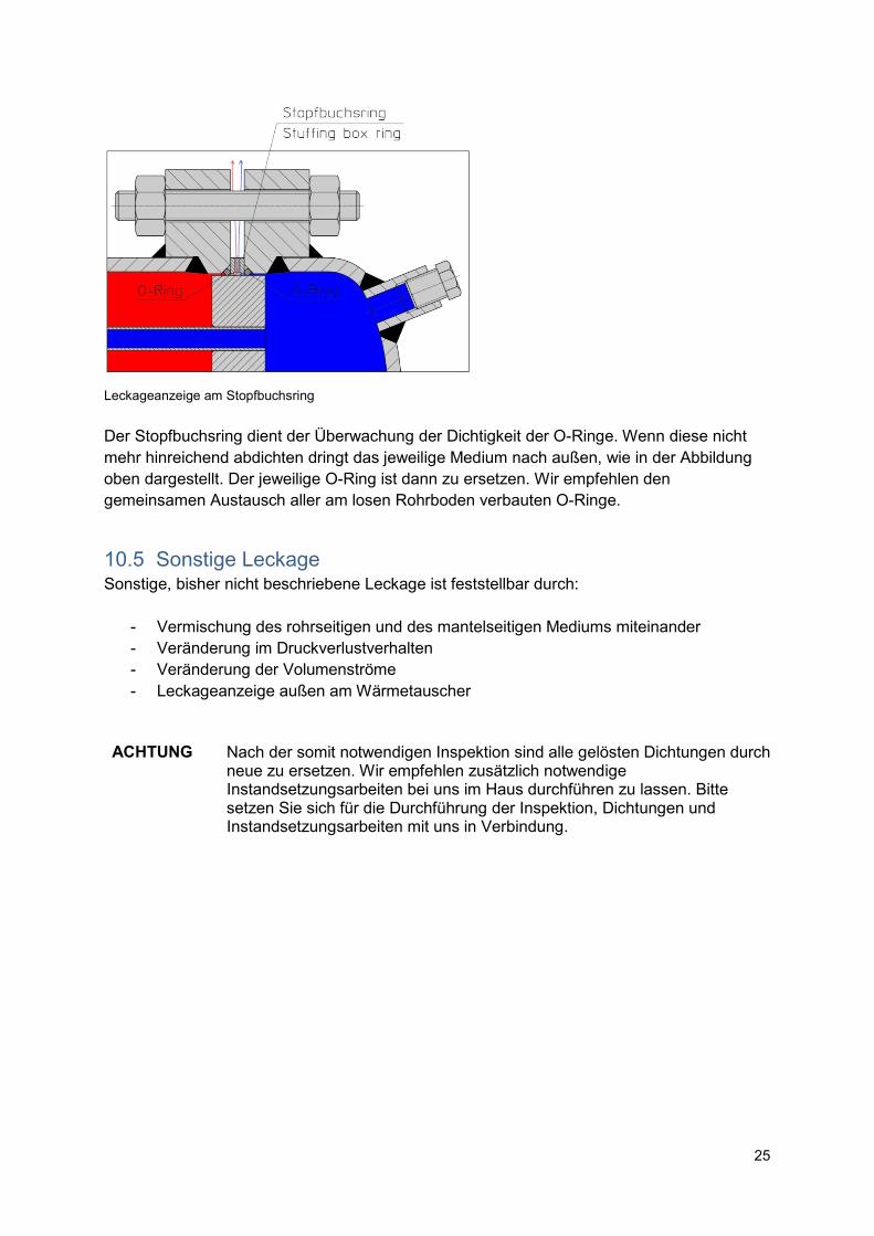
10.4 Austritt von Medium am Stopfbuchsring Bei einigen Bauformen trägt der Wärmetauscher auf der Seite des losen Rohrbodens einen Stopfbuchsring. Es handelt sich um einen Ring mit einer innen umlaufenden Nut und mehreren nach außen offenen Bohrungen am Umfang. Seitlich neben dem Stopfbuchsring dichten O-Ringe das rohrseitige und das mantelseitige Medium nach außen hin ab.
25
Leckageanzeige am Stopfbuchsring Der Stopfbuchsring dient der Überwachung der Dichtigkeit der O-Ringe. Wenn diese nicht mehr hinreichend abdichten dringt das jeweilige Medium nach außen, wie in der Abbildung oben dargestellt. Der jeweilige O-Ring ist dann zu ersetzen. Wir empfehlen den gemeinsamen Austausch aller am losen Rohrboden verbauten O-Ringe.
10.5 Sonstige Leckage Sonstige, bisher nicht beschriebene Leckage ist feststellbar durch:
- Vermischung des rohrseitigen und des mantelseitigen Mediums miteinander - Veränderung im Druckverlustverhalten - Veränderung der Volumenströme - Leckageanzeige außen am Wärmetauscher
ACHTUNG
Nach der somit notwendigen Inspektion sind alle gelösten Dichtungen durch neue zu ersetzen. Wir empfehlen zusätzlich notwendige Instandsetzungsarbeiten bei uns im Haus durchführen zu lassen. Bitte setzen Sie sich für die Durchführung der Inspektion, Dichtungen und Instandsetzungsarbeiten mit uns in Verbindung.
26
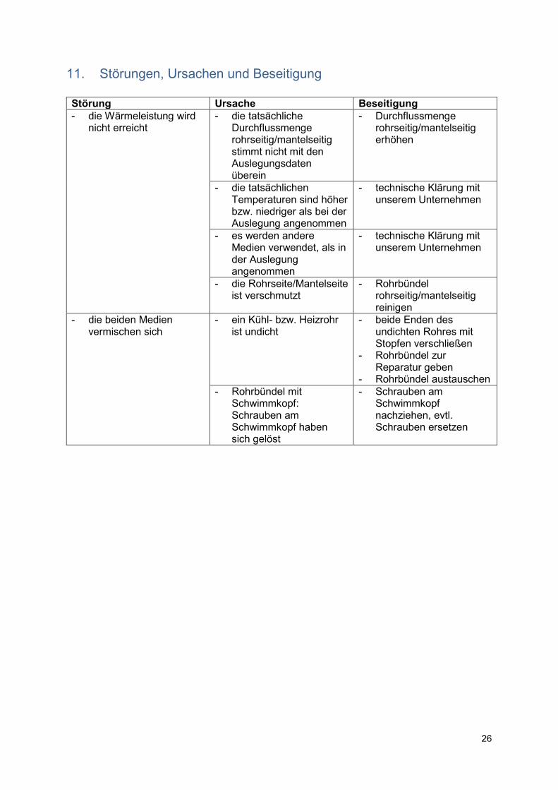
11. Störungen, Ursachen und Beseitigung
Störung Ursache Beseitigung
- die Wärmeleistung wird nicht erreicht
- die tatsächliche Durchflussmenge rohrseitig/mantelseitig stimmt nicht mit den Auslegungsdaten überein
- Durchflussmenge rohrseitig/mantelseitig erhöhen
- die tatsächlichen Temperaturen sind höher bzw. niedriger als bei der Auslegung angenommen
- technische Klärung mit unserem Unternehmen
- es werden andere Medien verwendet, als in der Auslegung angenommen
- technische Klärung mit unserem Unternehmen
- die Rohrseite/Mantelseite ist verschmutzt
- Rohrbündel rohrseitig/mantelseitig reinigen
- die beiden Medien vermischen sich
- ein Kühl- bzw. Heizrohr ist undicht
- beide Enden des undichten Rohres mit Stopfen verschließen
- Rohrbündel zur Reparatur geben
- Rohrbündel austauschen - Rohrbündel mit
Schwimmkopf: Schrauben am Schwimmkopf haben sich gelöst
- Schrauben am Schwimmkopf nachziehen, evtl. Schrauben ersetzen
27
1. General This operating manual contains basic instructions which must be observed during installation, operation and maintenance. Therefore, the operating instructions must be read by the installer and the competent specialist/operator prior to setting up and commissioning and must be available at all times at the site of the machine.
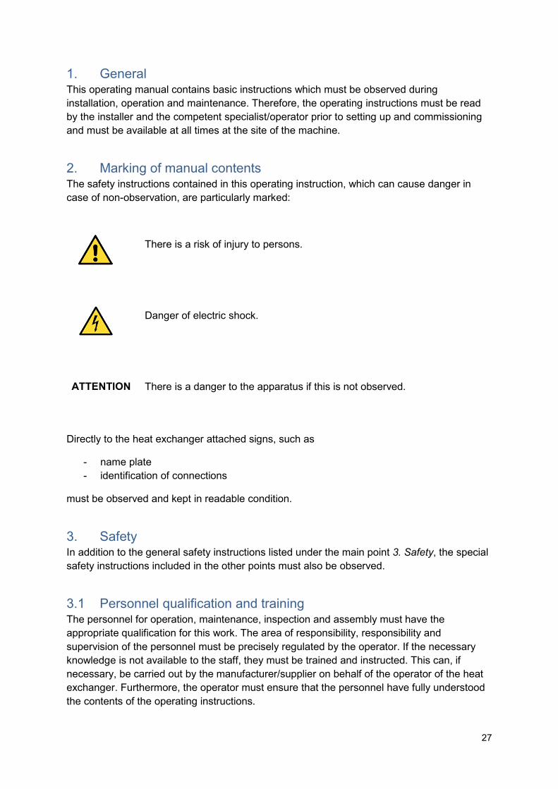
2. Marking of manual contents The safety instructions contained in this operating instruction, which can cause danger in case of non-observation, are particularly marked:
There is a risk of injury to persons.
Danger of electric shock.
ATTENTION
There is a danger to the apparatus if this is not observed.
Directly to the heat exchanger attached signs, such as
- name plate - identification of connections
must be observed and kept in readable condition.
3. Safety In addition to the general safety instructions listed under the main point 3. Safety, the special safety instructions included in the other points must also be observed.
3.1 Personnel qualification and training The personnel for operation, maintenance, inspection and assembly must have the appropriate qualification for this work. The area of responsibility, responsibility and supervision of the personnel must be precisely regulated by the operator. If the necessary knowledge is not available to the staff, they must be trained and instructed. This can, if necessary, be carried out by the manufacturer/supplier on behalf of the operator of the heat exchanger. Furthermore, the operator must ensure that the personnel have fully understood the contents of the operating instructions.
28
3.2 Risks of nonobservance of the safety instructions Failure to observe the safety instructions as well as the prescribed methods for maintenance and repair may result in a risk to persons as well as to the environment and the heat exchanger and will result in the loss of any claims for damages.
Specifically, non-respect may, for example, result in the following hazards:
- failure of important functions of the heat exchanger/sytem - danger to persons by electrical, mechanical, chemical and thermal exposure - danger to the environment due to leakage of hazardous substances
3.3 Safety conscious working The safety instructions of this manual, the existing national regulations on accident prevention as well as possible internal working, operating and safety regulations of the operator must be observed.
3.4 Safety instructions for the operator If hot or cold parts of the heat exchanger lead to dangers, these parts must be protected against contact by the customer.
Leakage of dangerous media, e.g. explosive, toxic or hot, must be discharged in such a way that no risk to persons and/or the environment arises. Legal provisions must be complied with.
Dangers caused by electrical energy are to be excluded. For details, e.g. contact the regulations of the VDE and the local power supply companies.
3.5 Safety during maintenance, inspection and assembly work The operator has to ensure that all maintenance, inspection and assembly work is carried out by authorized and qualified personnel, who have been sufficiently informed by a thorough study of the operating instructions.
Work on the heat exchanger must be carried out only after shutdown. The operating procedures described in the operating instructions must be strictly adhered to.
Heat exchangers that contain hazardous media must be decontaminated prior to an intervention.
Immediately after completion of the work on the heat exchanger, all safety and protective devices must be re-installed or put into operation.
Before re-commissioning, the points listed in section 8. Start-up must be observed.
3.6 Unauthorized modification and spare parts production Reconstruction or alteration of the heat exchanger is only permitted after consultation with the manufacturer.
29
Original spare parts and accessories authorized by the manufacturer are for safety reasons. The use of other parts excludes liability for the resulting consequences.
3.7 Unauthorized operation The operational safety of the delivered heat exchanger is only guaranteed when used as intended.
The stated limit values, which are stated in the order confirmation, in the brochure sheet or in data sheets, must under no circumstances be exceeded.
30
4. Operational area Heat exchangers are devices that transfer heat along a temperature gradient between two or more flowing media. The media involved may be liquid or gaseous. A change of the physical state of the media and/or other physical properties can be made with heat exchangers.
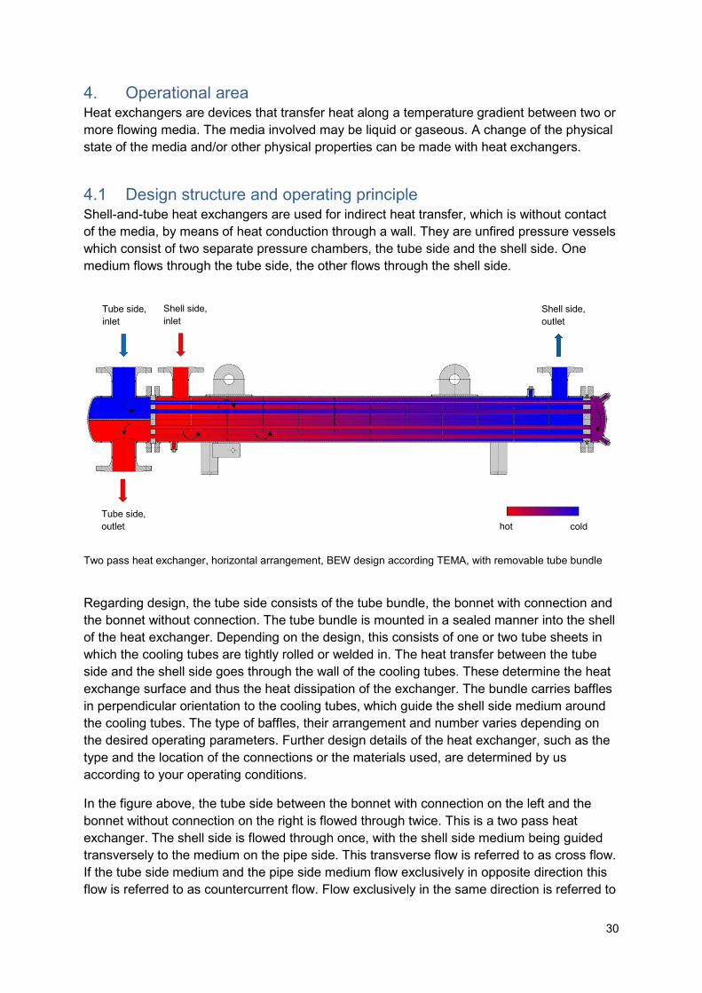
4.1 Design structure and operating principle Shell-and-tube heat exchangers are used for indirect heat transfer, which is without contact of the media, by means of heat conduction through a wall. They are unfired pressure vessels which consist of two separate pressure chambers, the tube side and the shell side. One medium flows through the tube side, the other flows through the shell side.
Two pass heat exchanger, horizontal arrangement, BEW design according TEMA, with removable tube bundle
Regarding design, the tube side consists of the tube bundle, the bonnet with connection and the bonnet without connection. The tube bundle is mounted in a sealed manner into the shell of the heat exchanger. Depending on the design, this consists of one or two tube sheets in which the cooling tubes are tightly rolled or welded in. The heat transfer between the tube side and the shell side goes through the wall of the cooling tubes. These determine the heat exchange surface and thus the heat dissipation of the exchanger. The bundle carries baffles in perpendicular orientation to the cooling tubes, which guide the shell side medium around the cooling tubes. The type of baffles, their arrangement and number varies depending on the desired operating parameters. Further design details of the heat exchanger, such as the type and the location of the connections or the materials used, are determined by us according to your operating conditions.
In the figure above, the tube side between the bonnet with connection on the left and the bonnet without connection on the right is flowed through twice. This is a two pass heat exchanger. The shell side is flowed through once, with the shell side medium being guided transversely to the medium on the pipe side. This transverse flow is referred to as cross flow. If the tube side medium and the pipe side medium flow exclusively in opposite direction this flow is referred to as countercurrent flow. Flow exclusively in the same direction is referred to
Tube side, inlet
Shell side, inlet
Tube side, outlet
Shell side, outlet
hot cold
31
as cocurrent flow. In the figure above the tube side medium first flows in cocurrent flow from the bonnet with connection to the bonnet without connection and then in countercurrent flow to the outlet.
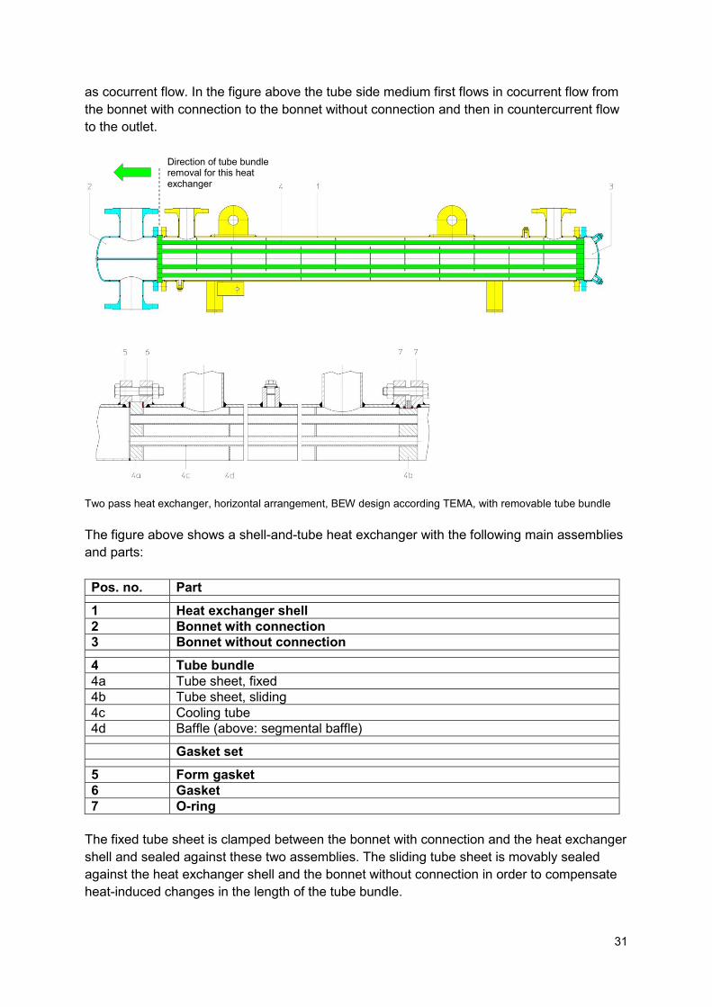
Two pass heat exchanger, horizontal arrangement, BEW design according TEMA, with removable tube bundle The figure above shows a shell-and-tube heat exchanger with the following main assemblies and parts:
Pos. no. Part
1 Heat exchanger shell 2 Bonnet with connection 3 Bonnet without connection
4 Tube bundle 4a Tube sheet, fixed 4b Tube sheet, sliding 4c Cooling tube 4d Baffle (above: segmental baffle)
Gasket set
5 Form gasket 6 Gasket 7 O-ring
The fixed tube sheet is clamped between the bonnet with connection and the heat exchanger shell and sealed against these two assemblies. The sliding tube sheet is movably sealed against the heat exchanger shell and the bonnet without connection in order to compensate heat-induced changes in the length of the tube bundle.
Direction of tube bundle removal for this heat exchanger
32
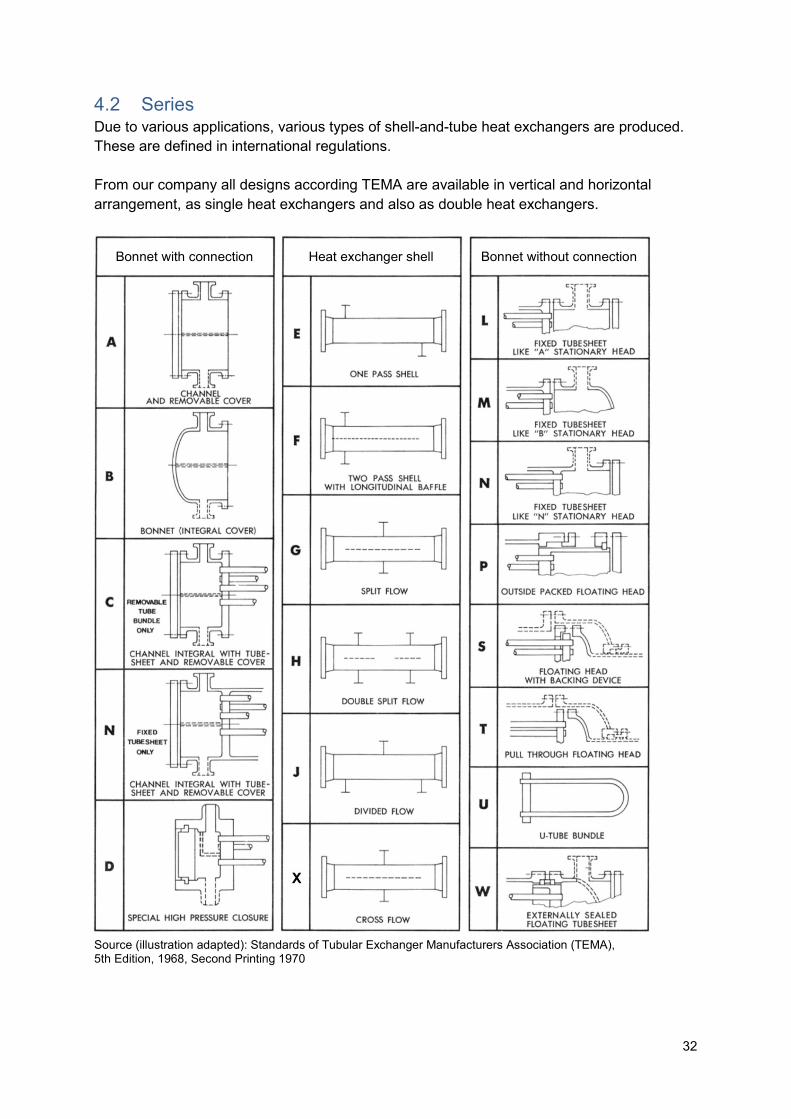
4.2 Series Due to various applications, various types of shell-and-tube heat exchangers are produced. These are defined in international regulations. From our company all designs according TEMA are available in vertical and horizontal arrangement, as single heat exchangers and also as double heat exchangers.
Source (illustration adapted): Standards of Tubular Exchanger Manufacturers Association (TEMA), 5th Edition, 1968, Second Printing 1970
Bonnet with connection Heat exchanger shell Bonnet without connection
33
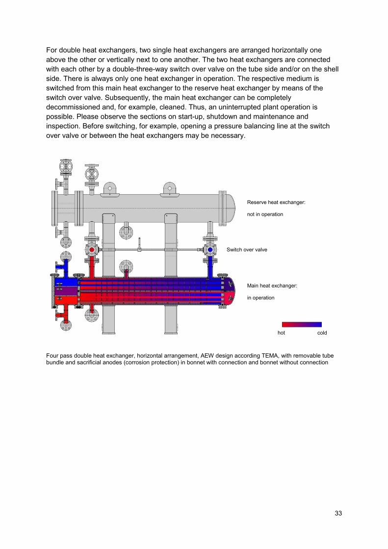
For double heat exchangers, two single heat exchangers are arranged horizontally one above the other or vertically next to one another. The two heat exchangers are connected with each other by a double-three-way switch over valve on the tube side and/or on the shell side. There is always only one heat exchanger in operation. The respective medium is switched from this main heat exchanger to the reserve heat exchanger by means of the switch over valve. Subsequently, the main heat exchanger can be completely decommissioned and, for example, cleaned. Thus, an uninterrupted plant operation is possible. Please observe the sections on start-up, shutdown and maintenance and inspection. Before switching, for example, opening a pressure balancing line at the switch over valve or between the heat exchangers may be necessary.
Four pass double heat exchanger, horizontal arrangement, AEW design according TEMA, with removable tube bundle and sacrificial anodes (corrosion protection) in bonnet with connection and bonnet without connection
hot cold
Reserve heat exchanger: not in operation
Switch over valve
Main heat exchanger: in operation
34
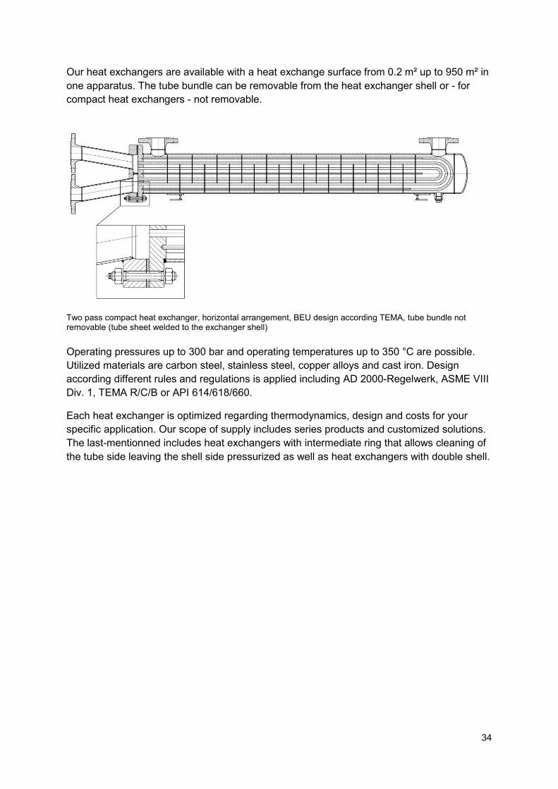
Our heat exchangers are available with a heat exchange surface from 0.2 m² up to 950 m² in one apparatus. The tube bundle can be removable from the heat exchanger shell or - for compact heat exchangers - not removable.
Two pass compact heat exchanger, horizontal arrangement, BEU design according TEMA, tube bundle not removable (tube sheet welded to the exchanger shell)
Operating pressures up to 300 bar and operating temperatures up to 350 °C are possible. Utilized materials are carbon steel, stainless steel, copper alloys and cast iron. Design according different rules and regulations is applied including AD 2000-Regelwerk, ASME VIII Div. 1, TEMA R/C/B or API 614/618/660.
Each heat exchanger is optimized regarding thermodynamics, design and costs for your specific application. Our scope of supply includes series products and customized solutions. The last-mentionned includes heat exchangers with intermediate ring that allows cleaning of the tube side leaving the shell side pressurized as well as heat exchangers with double shell.
35
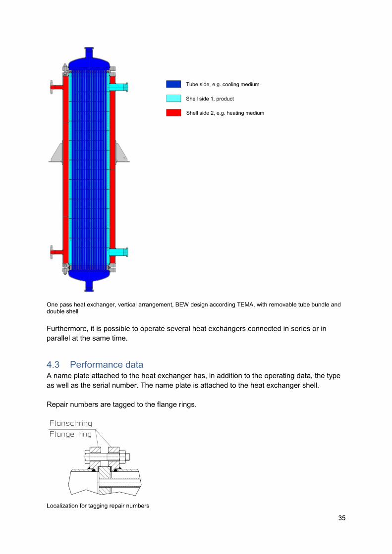
One pass heat exchanger, vertical arrangement, BEW design according TEMA, with removable tube bundle and double shell Furthermore, it is possible to operate several heat exchangers connected in series or in parallel at the same time.
4.3 Performance data A name plate attached to the heat exchanger has, in addition to the operating data, the type as well as the serial number. The name plate is attached to the heat exchanger shell. Repair numbers are tagged to the flange rings.
Localization for tagging repair numbers
Tube side, e.g. cooling medium
Shell side 1, product
Shell side 2, e.g. heating medium
36
Directly attached to the heat exchanger signs must be observed and kept in readable condition.
The serial number must always be indicated in case of queries, repeat orders and, in
particular, when ordering spare parts.
The thermodynamical design data are different for almost every heat exchanger.If necessary, these data can be requested from us in the form of a data sheet.
4.4 Areas of application ATTENTION
The heat exchanger must be operated only for the applications approved by the manufacturer.
5. Transport
The transport has to be carried out in a professional manner. The weight stated on the name plate must be observed.
The unpacked heat exchanger is attached to crane installations by means of transport loops placed around the shell tube or by attaching to the lifting lugs provided for this purpose on the heat exchanger shell.
Additional lifting lugs or eye bolts attached, for example, to the bonnet with connection and/or the bonnet without connection, do not serve to lift the entire heat exchanger but only to lift the individual assembly in the disassembled state !
ATTENTION
Heat exchangers must be adequately protected against corrosive influences, impacts and shocks in order to avoid leakage and component failure. In addition, damage of the shell tube can lead to difficulties in pulling the tube bundle.
37
ATTENTION
The inlet and outlet of the heat exchanger must be equipped with protective plugs. This measure is necessary to protect the interior from corrosion and to prevent the leakage of residual liquid or the penetration of foreign objects.
6. Storage Heat exchangers are to be stored in dry conditions. The protective plugs at the inlets and outlets should remain in place until the heat exchanger is used. If the heat exchangers are to be stored for more than six months before use, corrosion protection measures should be taken for bare metal parts of the heat exchangers.
7. Installation Before installation, check the heat exchanger for transport damage and contamination.
The place of installation should be chosen so that the heat exchanger is easily accessible, in particular, vent and drain connections.
There must be sufficient space for inspection and maintenance work, in particular for removing the entire heat exchanger or pulling the tube bundle on site. Please consider the pull-out direction and the pull-out length of the tube bundle.
The heat exchanger must be mounted on a horizontal, level and firm base. In the case of uneven ground, it must be supported by material, cement spout or equivalent.
ATTENTION
Each heat exchanger expands during start-up by the heating up of the material and contracts again during shut-down with cooling down. The tube bundle is mounted in the heat exchanger shell in such a way that the tube bundle expands within the heat exchanger. Irrespective of this, the heat exchanger shell expands. The feet of horizontal apparatus, therefore, are designed as a fixed saddle on the one side and a sliding saddle on the other side.
38
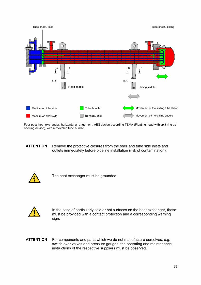
Four pass heat exchanger, horizontal arrangement, AES design according TEMA (Floating head with split ring as backing device), with removable tube bundle ATTENTION
Remove the protective closures from the shell and tube side inlets and outlets immediately before pipeline installation (risk of contamination).
The heat exchanger must be grounded.
In the case of particularly cold or hot surfaces on the heat exchanger, these must be provided with a contact protection and a corresponding warning sign.
ATTENTION
For components and parts which we do not manufacture ourselves, e.g. switch over valves and pressure gauges, the operating and maintenance instructions of the respective suppliers must be observed.
Tube sheet, fixed Tube sheet, sliding
Medium on tube side
Medium on shell side
Tube bundle
Bonnets, shell
Fixed saddle
Sliding saddle
Movement of the sliding tube sheet
Movement oft he sliding saddle
39
7.1 Pipelines
ATTENTION
Pipelines must be cleaned before connecting. They must be free of scale, welding residues, sand, chips and beginning rust. The connection must be free of stress.
ATTENTION
The pipelines must be sufficiently dimensioned. They must not be smaller than the nominal size of the heat exchanger connections. Bends required in the pipelines may be executed with a radius as large as possible.
8. Start-up
ATTENTION
Remove all conservation and closures which have been attached or inserted for the transport and storage of the heat exchanger.
ATTENTION
Before connecting to the pipeline system, check the correct flow directions for the heat exchanger using the order specific documentation. This allocation of inlets and outlets to the correct connections can be done, for example, with the help of our dimensional drawing.
In addition to the inlet and outlet connections the heat exchanger has devices for venting or darining. For this purpose, sleeves with a plug are provided standardly, alternatively flanged versions.
The venting is at the highest point of the respective pressure chamber, the draining is at its lowest. If such separate vents and/or drains are not present, the venting and/or draining takes place via the outlet of the respective medium during operation.
ATTENTION
For connecting the heat exchanger to the pipeline system always new gaskets must be used.
Heat exchangers shall be put into operation as evenly as possible. Pressure shocks must be avoided. The agreed limits for operation must be complied with.
40
After connecting the heat exchanger to the pipeline system the single steps for start-up are as follows:
- for heat exchangers with switch over valve:
o make sure that the switch over valve is switched to the correct heat exchanger o close the pressure balancing line at the switch over valve or between the heat
exchangers for the medium flowing only into the exchanger that shall be put into operation
o the operating manual of the supplier of the switch over valve must be considered
- for further valves and instruments, as manometers, safety valves or bursting disks the operating manual of the respective supplier must be considered
- make sure that all vents and drains are closed - open all outlets of the heat exchanger - open the inlet of the medium which is heating up during operation (cooling medium) - open the inlet of the medium that is cooling down during operation (heating medium) - vent the cooling medium - vent the heating medium - adjust the cooling and heating medium to the desired operating point
For further pressure chambers on the heat exchanger, for example on heat exchangers with a double shell, an analogous procedure is to be followed.
When starting with media of high viscosity, temporarily high pressure losses can occur. Therefore it is advisable in some cases to provide a bypass control for the cold start.
ATTENTION
Due to the partial high temperature changes during start-up and settling, small leaks can occur at the outer sealing connections, for example on pipe connections and flange rings. These can be removed by tightening the screws slightly.
Longer standstill is to be avoided because of the increased risk of corrosion. For longer standstill, the heat exchanger must be flushed if necessary and drained completely in all cases.
8.1 Switching of double heat exchangers after start-up The single steps of switching a double heat exchanger with switch over valve on the shell side and without switch over valve on the tube side is described below. It is assumed that the cooling medium flows on the tube side and the heating medium flows on the shell side:
- make sure that the vents and drains of the reserve heat exchanger are closed - open the outlets of the reserve heat exchanger - open the inlet of the cooling medium at the reserve heat exchanger - open the pressure balancing line at the switch over valve or between the two shell
sides; the operating manual of the switch over valve must be considered
41
- switch the shell side medium - close the pressure balancing line - close the inlet of the cooling medium at the heat exchanger that is put out of
operation - close the outlet of the cooling medium at the heat exchange that is put out of
operation - vent the tube side of the reserve heat exchanger (cooling medium) - vent the shell side of the reserve heat exchanger (heating medium) - adjust the cooling and heating medium to the desired operating point - decommission the heat exchanger that is put out of operation
9. Shutdown
ATTENTION
For longer periods of standstill without disassembling, for inspection or at risk of frost, the heat exchanger must be drained respectively protected against freezing.
For draining, first disconnect the heat exchanger from the system, for example by closing shut-off valves and then relieve pressure. Then first open the vent and afterwards the drain of the respective pressure chamber. Collect medium that flows out. The filling quantities of the heat exchanger are indicated on the name plate. The heat exchanger must be completely drained.
If the heat exchanger contains residual amounts of hazardous substances, e.g. toxic or corrosive, then the corresponding marking for overhaul, safe storage and re-commissioning must be made. The marking must be made according to the relevant regulations.
For storage, the heat exchanger must be closed and conserved accordingly.
10. Maintenance and inspection Regular maintenance is essential for the safe operation of plants. The scope and intervals must be adapted to the requirements on site.
The first inspection must be carried out immediately after start-up. The subsequent maintenance interval should initially be at most one week. If it has been proven that there is no change in the operating behavior of the heat exchanger, the maintenance interval can be extended. The length of the maintenance interval is determined by the operator. Visual inspections at the beginning of the shift and necessary cleaning work must never be omitted.
Especially in the case of longer standstill settling can occur at gaskets. A slight tightening then is necessary at these locations.
42
When the flow rates are fixed, operation monitoring is possible with the aid of temperature and pressure measurement at the inlet and at the outlet of the tube and shell side. A change in the temperature or pressure difference between inlet and outlet may indicate fouling or the necessity of venting.
We recommend the documentation of the type and scope of maintenance as well as the relevant measured values. A change in the operating data can thereby be recognized most quickly.
Regular checking and cleaning of filters at or before inlet and further dirt separators installed in the system is essential.
The regular cleaning of the heat exchanger ensures an efficient heat transfer and a long, trouble-free operating time. Due to the various types of heat exchangers, please contact us for the exact way of cleaning.
ATTENTION
If, for any reason, an opening of the heat exchanger is required, care must be taken that new and identical seals are used with regard to geometry and type of material for re-commissioning.
ATTENTION
We recommend to carry out repairs at the manufacturer.
Please note that work carried out on the heat exchanger itself during the warranty period will void the guarantee. We assume no liability for damage directly or indirectly caused by work on the heat exchanger, for example at the heat exchanger itself, at connected plant parts, persons or the environment.
10.1 Cleaning of the heat exchanger If pressure drop and temperatures rise above the normal level, this can be due to fouling of the heat exchanger if the operating behavior was normal before.
The heat exchanger must then be taken out of operation and must be cleaned. This requires a complete draining of the heat exchanger from all media. Possibly existing inner and outer protective paints must not be damaged.
The bonnet with connection and the bonnet without connection, the respective bonnet cover or the floating head are removed and the inner surface of the cooling or heating tubes is cleaned with a suitable pipe cleaning brush. Care must be taken to ensure that the cooling tubes and their corrosion protection layer (passive layer) are not damaged. All residues in the tubes and bonnets must be completely removed. Finally, rinse with a suitable medium.
43
In the case of heat exchangers with an intermediate ring, the inside of the cooling tubes can be cleaned without relieving the pressure on the shell side. For this purpose, the screw connection of the intermediate ring, which is located on the side of the sliding tube sheet and the screw connection of the fixed tube sheet, must not be released.
For the cleaning of the tube bundle around the tubes the tube bundle must be removed from the shell. The installation position of the bundle should be marked before removal. Care must be taken to avoid deformation of the shell during operation, as difficulties may arise when removing the tube bundle.
When pulling the tube bundle out of the shell, this is first carefully pulled out to 75% of the bundle length. Subsequently, further transport loops are put around the bundle so that it cannot fall down when it is completely pulled out.
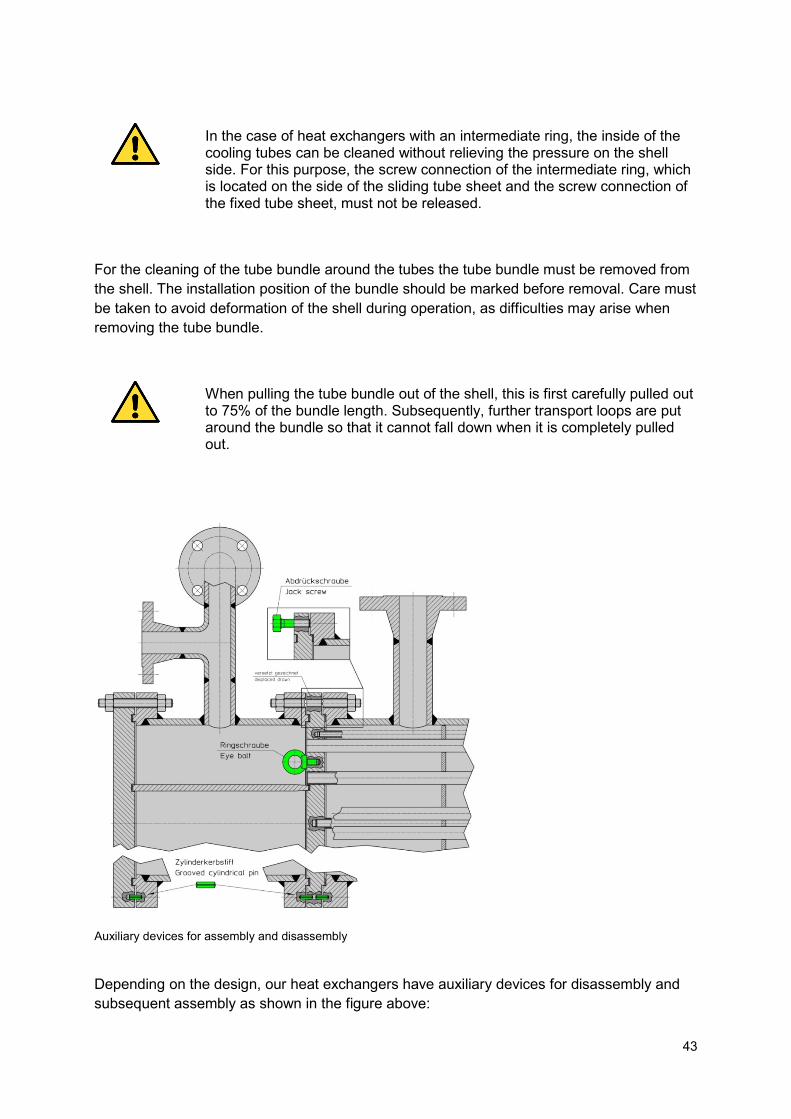
Auxiliary devices for assembly and disassembly
Depending on the design, our heat exchangers have auxiliary devices for disassembly and subsequent assembly as shown in the figure above:
44
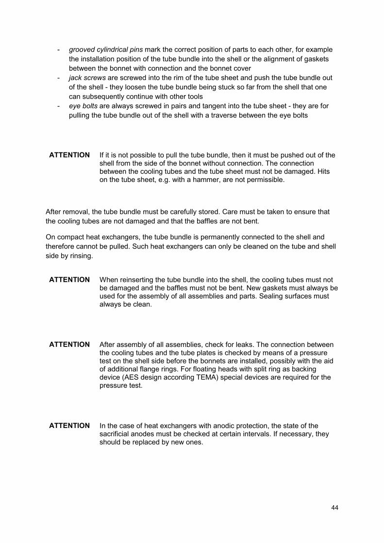
- grooved cylindrical pins mark the correct position of parts to each other, for example the installation position of the tube bundle into the shell or the alignment of gaskets between the bonnet with connection and the bonnet cover
- jack screws are screwed into the rim of the tube sheet and push the tube bundle out of the shell - they loosen the tube bundle being stuck so far from the shell that one can subsequently continue with other tools
- eye bolts are always screwed in pairs and tangent into the tube sheet - they are for pulling the tube bundle out of the shell with a traverse between the eye bolts
ATTENTION
If it is not possible to pull the tube bundle, then it must be pushed out of the shell from the side of the bonnet without connection. The connection between the cooling tubes and the tube sheet must not be damaged. Hits on the tube sheet, e.g. with a hammer, are not permissible.
After removal, the tube bundle must be carefully stored. Care must be taken to ensure that the cooling tubes are not damaged and that the baffles are not bent.
On compact heat exchangers, the tube bundle is permanently connected to the shell and therefore cannot be pulled. Such heat exchangers can only be cleaned on the tube and shell side by rinsing.
ATTENTION
When reinserting the tube bundle into the shell, the cooling tubes must not be damaged and the baffles must not be bent. New gaskets must always be used for the assembly of all assemblies and parts. Sealing surfaces must always be clean.
ATTENTION
After assembly of all assemblies, check for leaks. The connection between the cooling tubes and the tube plates is checked by means of a pressure test on the shell side before the bonnets are installed, possibly with the aid of additional flange rings. For floating heads with split ring as backing device (AES design according TEMA) special devices are required for the pressure test.
ATTENTION
In the case of heat exchangers with anodic protection, the state of the sacrificial anodes must be checked at certain intervals. If necessary, they should be replaced by new ones.
45
10.2 Localization of leaking cooling tubes During operation a leaking cooling tubes, a leaking connection between the cooling tube and the tube sheet or a broken tube usually occur as follows:
- mixing of the tube side and the shell side medium - change in the pressure loss behavior - change in the volume flows
If leakage occurs in the heat exchanger, it is of utmost importance to know the location of the leaking cooling tube in the tube bundle as well as the type and position of the leak point in the tube. This is the only way to identify the cause of the damage and provide appropriate remedies. To locate the leak, the heat exchanger must be shut down. The tube sheets must be given access to and they must be adequately cleaned. The leaking cooling tubes can be determined as follows:
a) The cooling tubes are individually pressed with air. A drop in the test pressure indicates a tube leak. Leaky connections between tube and tube sheet cannot be detected with this method
b) The tube bundle is inserted into the shell and provided with separate, loose flange rings (test rings, for floating heads with split ring as backing device: device for pressure test) at both ends. The tube sheets are sprayed with a leak detection spray and the tube bundle is pressed with a maximum of 0.3 bar of air on the shell side. With this method it is also possible to detect leaky connections between tube and tube sheet
10.3 Plugging of leaking cooling tubes After the allocation of a cooling tube leakage leaking cooling tubes must be sealed as quickly as possible to avoid consequential damage.
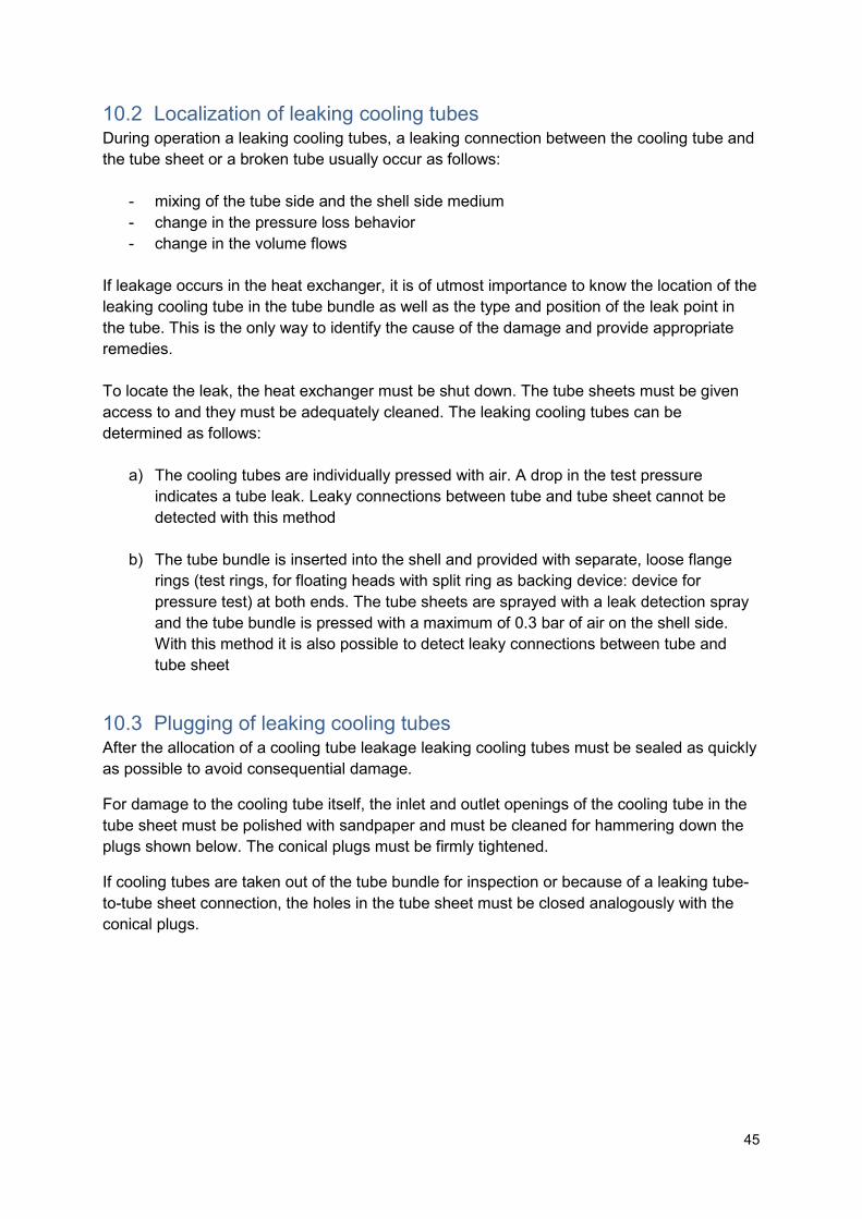
For damage to the cooling tube itself, the inlet and outlet openings of the cooling tube in the tube sheet must be polished with sandpaper and must be cleaned for hammering down the plugs shown below. The conical plugs must be firmly tightened.
If cooling tubes are taken out of the tube bundle for inspection or because of a leaking tube-to-tube sheet connection, the holes in the tube sheet must be closed analogously with the conical plugs.
46
ØD1 s ØD2 ØD3 L1 ØD4 L2
[mm] [mm] [mm] [mm] [mm] [mm] [mm] 10 1 9 7 30 M6 15 12 1 11 9 30 M6 15 15 1 14 12 40 M6 15 16 1 15 13 40 M6 15 16 1.25 14.5 12.5 40 M6 15 16 1.5 14 12 40 M6 15 18 1 17 15 40 M6 15 19 1.25 17.5 15.5 40 M6 15 19 1.65 16.7 14.7 40 M6 15
Plugs for sealing of cooling tubes and/or bore holes in tube sheets
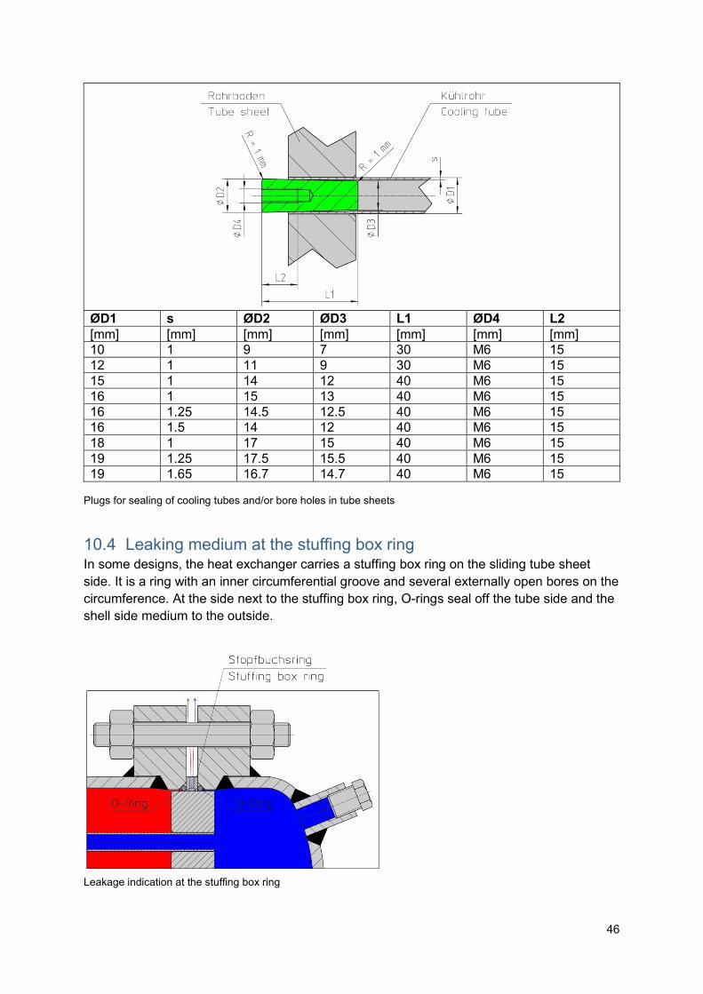
10.4 Leaking medium at the stuffing box ring In some designs, the heat exchanger carries a stuffing box ring on the sliding tube sheet side. It is a ring with an inner circumferential groove and several externally open bores on the circumference. At the side next to the stuffing box ring, O-rings seal off the tube side and the shell side medium to the outside.
Leakage indication at the stuffing box ring
47
The stuffing box ring is used to monitor the tightness of the O-rings. If these no longer seal adequately, the respective medium penetrates to the outside, as shown in the figure above. The respective O-ring must then be replaced. We recommend the joint replacement of all O-rings installed on the loose tube.
10.5 Other leakage Other leakage, which has not yet been described, can be detected by:
- mixing of the tube side and the shell side medium with one another - change in the pressure loss behavior - change in the volume flows - leakage indication on the outside of the heat exchanger
ATTENTION
After the therefore necessary inspection all disassembled gaskets must be replaced by new ones. We recommend that further necessary repairs may be carried out at our company. Please contact us for carrying out the inspection, for gaskets and repair work.
48
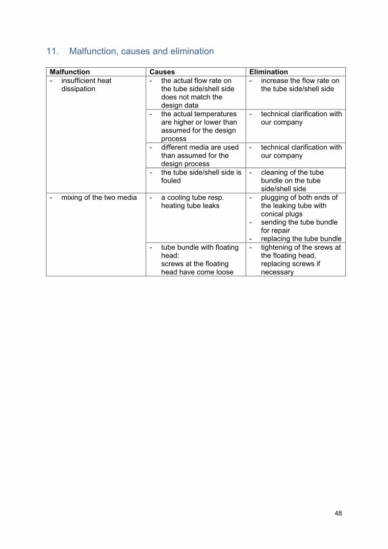
11. Malfunction, causes and elimination
Malfunction Causes Elimination
- insufficient heat dissipation
- the actual flow rate on the tube side/shell side does not match the design data
- increase the flow rate on the tube side/shell side
- the actual temperatures are higher or lower than assumed for the design process
- technical clarification with our company
- different media are used than assumed for the design process
- technical clarification with our company
- the tube side/shell side is fouled
- cleaning of the tube bundle on the tube side/shell side
- mixing of the two media - a cooling tube resp. heating tube leaks
- plugging of both ends of the leaking tube with conical plugs
- sending the tube bundle for repair
- replacing the tube bundle - tube bundle with floating
head: screws at the floating head have come loose
- tightening of the srews at the floating head, replacing screws if necessary