Embed Size (px)
Citation preview
QUICK DIE CHANGE
GÜ
TH
LE P
RE
SS
EN
SP
AN
NE
N G
MB
HR
OLL
BLO
C P
RO
DU
CT
-CA
TA
LOG
UE
ED
ITIO
N 5
Güthle Pressenspannen GmbHGottlieb-Haefele-Strasse 9
73061 Ebersbach
GERMANY
Phone: +49 7163 99090
Fax: +49 7163 990990
www.guthle.com
Breite: 65 mmStrichstärke: 0,3mmGröße wie Katalog
Breite: 65 mmStrichstärke: 0,3mmGröße wie Katalog
IDEA AND SYSTEMS
ROLLBLOC PRODUCT CATALOGUE
IDEA AND SYSTEMS
Breite: 65 mmStrichstärke: 0,3mmGröße wie KatalogCHANGING TECHNOLOGY
C CARRYING C MOVING C CLAMPING
Breite: 65 mmStrichstärke: 0,3mmGröße wie Katalog
�
C HIGH-QUALITY COMPONENTS FOR RELIABLE FUNCTIONALITY
RB-GB-102016Errors and omission excepted,subject to technical modifications.All measures in mm.
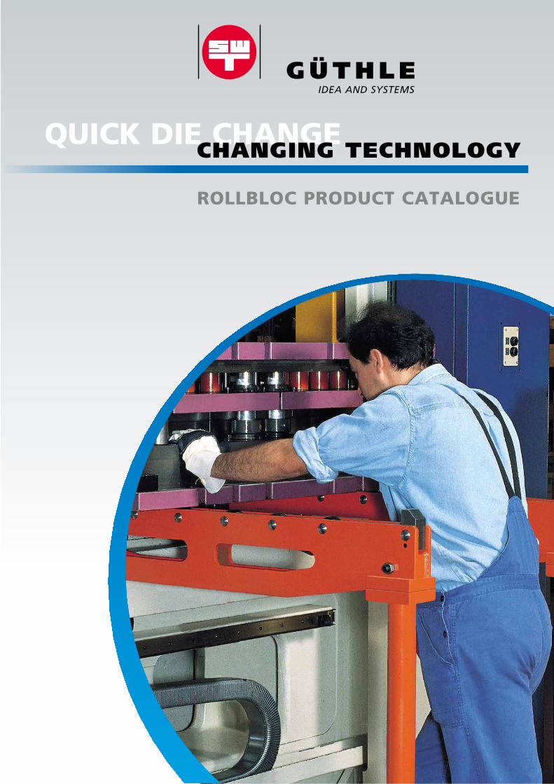
Hydraulic die clamping withROLLBLOC sliding clamps
Fast and reliable die transferbetween ROLLBLOC-BUGGY
and press table, equippedwith ROLLBLOC die lifters
Automated die changing with thetrack-mounted die transporterDILOS SHUTTLE. Separate productinformation is available on theGÜTHLE DILOS range.
Safe and reliable die changingwith ROLLBLOC die loading armsand ROLLBLOC die lifters
Hydraulic valves to control theROLLBLOC clamps and ROLLBLOC die lifterson mounting plate
ROLLBLOC Hydraulic Unit (Rear Side)with pump and control valveswith frame structure
ROLLBLOC Hydraulic Unitwith operating panel and controls
1
Breite: 65 mmStrichstärke: 0,3mmGröße wie Katalog
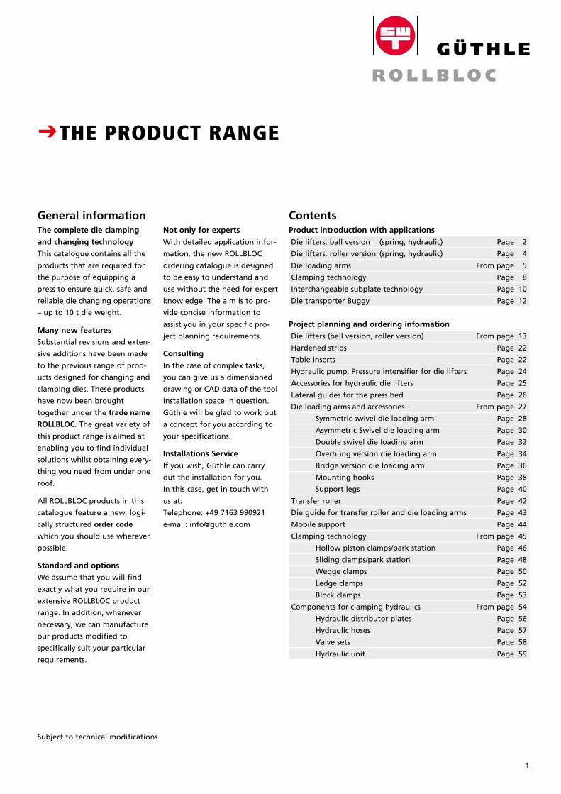
Product introduction with applications
Die lifters, ball version (spring, hydraulic) Page 2
Die lifters, roller version (spring, hydraulic) Page 4
Die loading arms From page 5
Clamping technology Page 8
Interchangeable subplate technology Page 10
Die transporter Buggy Page 12
Project planning and ordering information
Die lifters (ball version, roller version) From page 13
Hardened strips Page 22
Table inserts Page 22
Hydraulic pump, Pressure intensifier for die lifters Page 24
Accessories for hydraulic die lifters Page 25
Lateral guides for the press bed Page 26
Die loading arms and accessories From page 27
Symmetric swivel die loading arm Page 28
Asymmetric Swivel die loading arm Page 30
Double swivel die loading arm Page 32
Overhung version die loading arm Page 34
Bridge version die loading arm Page 36
Mounting hooks Page 38
Support legs Page 40
Transfer roller Page 42
Die guide for transfer roller and die loading arms Page 43
Mobile support Page 44
Clamping technology From page 45
Hollow piston clamps/park station Page 46
Sliding clamps/park station Page 48
Wedge clamps Page 50
Ledge clamps Page 52
Block clamps Page 53
Components for clamping hydraulics From page 54
Hydraulic distributor plates Page 56
Hydraulic hoses Page 57
Valve sets Page 58
Hydraulic unit Page 59
Not only for experts
With detailed application infor-
mation, the new ROLLBLOC
ordering catalogue is designed
to be easy to understand and
use without the need for expert
knowledge. The aim is to pro-
vide concise information to
assist you in your specific pro-
ject planning requirements.
Consulting
In the case of complex tasks,
you can give us a dimensioned
drawing or CAD data of the tool
installation space in question.
Güthle will be glad to work out
a concept for you according to
your specifications.
Installations Service
If you wish, Güthle can carry
out the installation for you.
In this case, get in touch with
us at:
Telephone: +49 7163 990921
e-mail: [email protected]
Subject to technical modifications
The complete die clamping
and changing technology
This catalogue contains all the
products that are required for
the purpose of equipping a
press to ensure quick, safe and
reliable die changing operations
– up to 10 t die weight.
Many new features
Substantial revisions and exten-
sive additions have been made
to the previous range of prod-
ucts designed for changing and
clamping dies. These products
have now been brought
together under the trade name
ROLLBLOC. The great variety of
this product range is aimed at
enabling you to find individual
solutions whilst obtaining every-
thing you need from under one
roof.
All ROLLBLOC products in this
catalogue feature a new, logi-
cally structured order code
which you should use wherever
possible.
Standard and options
We assume that you will find
exactly what you require in our
extensive ROLLBLOC product
range. In addition, whenever
necessary, we can manufacture
our products modified to
specifically suit your particular
requirements.
CTHE PRODUCT RANGE
ContentsGeneral information
CEASY HANDLING AND PRECISION POSITIONING OF DIES WEIGHING TONS
Fast
handling –
protective
die changing
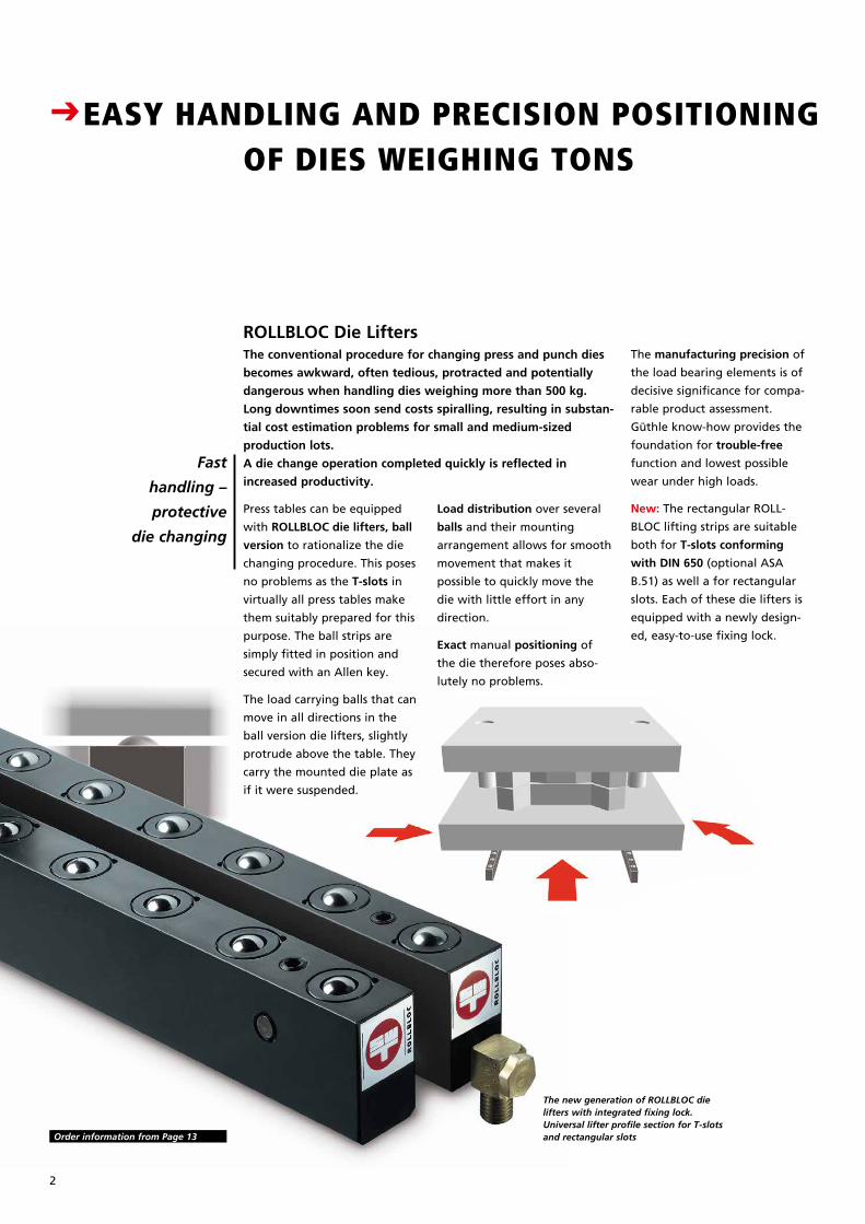
ROLLBLOC Die LiftersThe manufacturing precision of
the load bearing elements is of
decisive significance for compa-
rable product assessment.
Güthle know-how provides the
foundation for trouble-free
function and lowest possible
wear under high loads.
New: The rectangular ROLL-
BLOC lifting strips are suitable
both for T-slots conforming
with DIN 650 (optional ASA
B.51) as well a for rectangular
slots. Each of these die lifters is
equipped with a newly design -
ed, easy-to-use fixing lock.
The conventional procedure for changing press and punch dies
becomes awkward, often tedious, protracted and potentially
dangerous when handling dies weighing more than 500 kg.
Long downtimes soon send costs spiralling, resulting in substan-
tial cost estimation problems for small and medium-sized
production lots.
A die change operation completed quickly is reflected in
increased productivity.
Press tables can be equipped
with ROLLBLOC die lifters, ball
version to rationalize the die
changing procedure. This poses
no problems as the T-slots in
virtually all press tables make
them suitably prepared for this
purpose. The ball strips are
simply fitted in position and
secured with an Allen key.
The load carrying balls that can
move in all directions in the
ball version die lifters, slightly
protrude above the table. They
carry the mounted die plate as
if it were suspended.
Load distribution over several
balls and their mounting
ar range ment allows for smooth
movement that makes it
possible to quickly move the
die with little effort in any
direction.
Exact manual positioning of
the die therefore poses abso-
lutely no problems.
The new generation of ROLLBLOC die lifters with integrated fixing lock. Universal lifter profile section for T-slots and rectangular slots Order information from Page 13
2
Breite: 65 mmStrichstärke: 0,3mmGröße wie Katalog
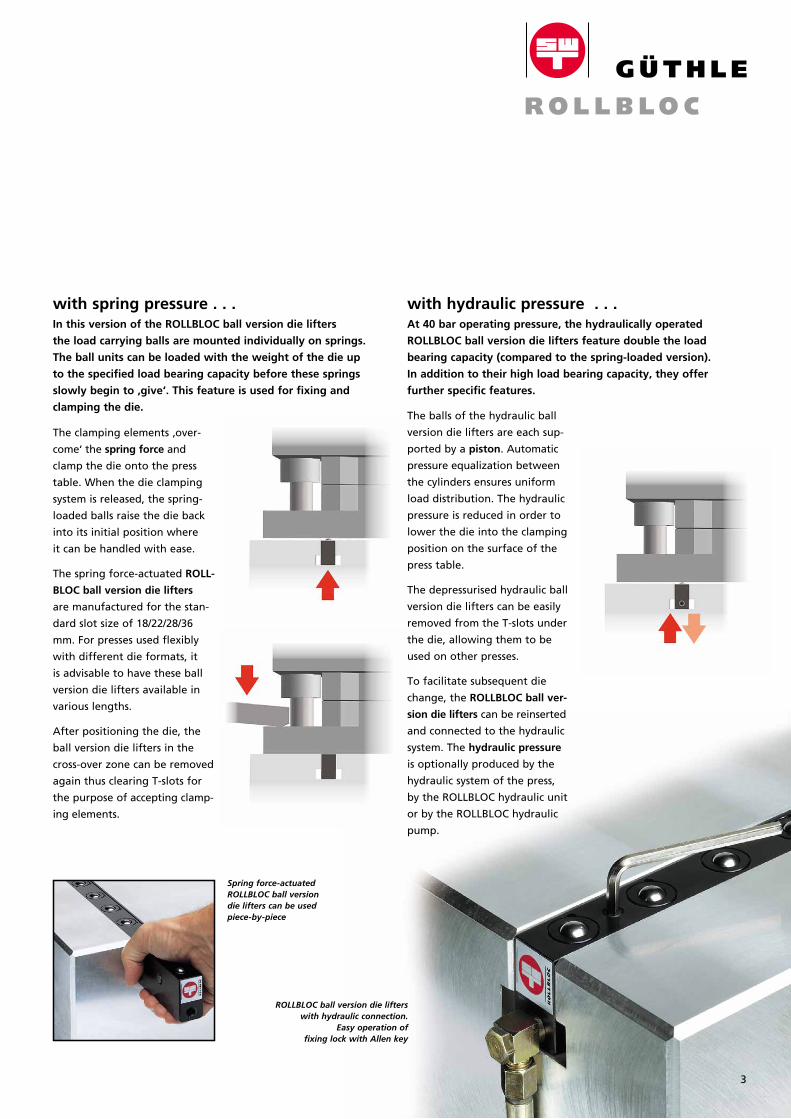
with spring pressure . . . with hydraulic pressure . . .
The clamping elements ‚over-
come‘ the spring force and
clamp the die onto the press
table. When the die clamping
system is released, the spring-
loaded balls raise the die back
into its initial position where
it can be handled with ease.
The spring force-actuated ROLL-
BLOC ball version die lifters
are manufactured for the stan-
dard slot size of 18/22/28/36
mm. For presses used flexibly
with different die formats, it
is advisable to have these ball
version die lifters available in
various lengths.
After positioning the die, the
ball version die lifters in the
cross-over zone can be removed
again thus clear ing T-slots for
the purpose of accepting clamp-
ing elements.
In this version of the ROLLBLOC ball version die lifters
the load carrying balls are mounted individually on springs.
The ball units can be loaded with the weight of the die up
to the specified load bearing capacity before these springs
slowly begin to ‚give‘. This feature is used for fixing and
clamping the die.
Spring force-actuated ROLLBLOC ball version die lifters can be used piece-by-piece
ROLLBLOC ball version die lifters with hydraulic connection.
Easy operation of fixing lock with Allen key
CEASY HANDLING AND PRECISION POSITIONING OF DIES WEIGHING TONS
The balls of the hydraulic ball
version die lifters are each sup-
ported by a piston. Automatic
pressure equalization between
the cylinders ensures uniform
load distribution. The hydraulic
pressure is reduced in order to
lower the die into the clamping
position on the surface of the
press table.
The depressurised hydraulic ball
version die lifters can be easily
removed from the T-slots under
the die, allowing them to be
used on other presses.
To facilitate subsequent die
change, the ROLLBLOC ball ver-
sion die lifters can be reinserted
and connected to the hydraulic
system. The hydraulic pressure
is optionally produced by the
hydraulic system of the press,
by the ROLLBLOC hydraulic unit
or by the ROLLBLOC hydraulic
pump.
At 40 bar operating pressure, the hydraulically operated
ROLL BLOC ball version die lifters feature double the load
bearing capacity (compared to the spring-loaded version).
In addition to their high load bearing capacity, they offer
further specific features.
3
For highest
loads
and exact
linear
traverse paths
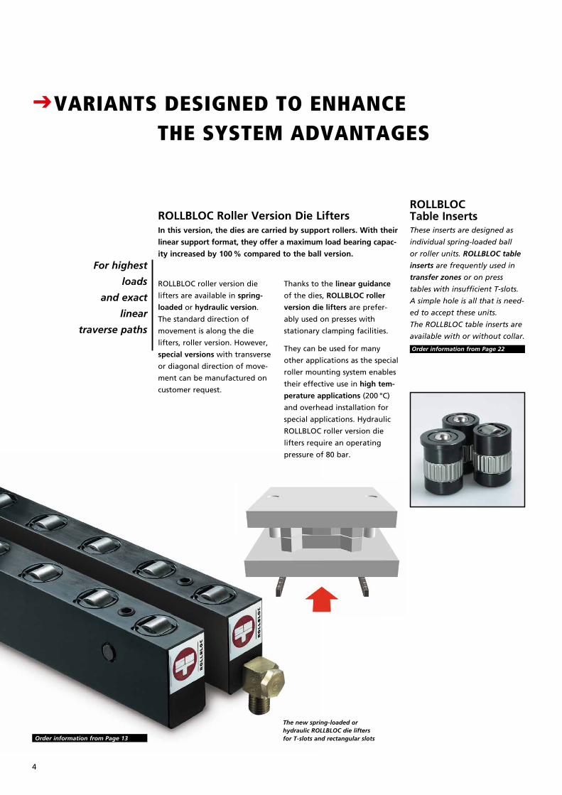
ROLLBLOC Roller Version Die Lifters ROLLBLOC Table Inserts
ROLLBLOC roller version die
lifters are available in spring-
loaded or hydraulic version.
The standard direction of
movement is along the die
lifters, roller version. However,
special versions with transverse
or diagonal direction of move-
ment can be manufactured on
customer request.
These inserts are designed as
individual spring-loaded ball
or roller units. ROLLBLOC table
inserts are frequently used in
transfer zones or on press
tables with insufficient T-slots.
A simple hole is all that is need-
ed to accept these units.
The ROLLBLOC table inserts are
available with or without collar.
In this version, the dies are carried by support rollers. With their
linear support format, they offer a maximum load bearing capac-
ity increased by 100 % compared to the ball version.
Order information from Page 22
The new spring-loaded or hydraulic ROLLBLOC die lifters for T-slots and rectangular slots
Thanks to the linear guidance
of the dies, ROLLBLOC roller
version die lifters are prefer-
ably used on presses with
stationary clamping facilities.
They can be used for many
other applications as the special
roller mounting system enables
their effective use in high tem-
perature applications (200 °C)
and overhead installation for
special applications. Hydraulic
ROLLBLOC roller version die
lifters require an operating
pressure of 80 bar.
Order information from Page 13
CVARIANTS DESIGNED TO ENHANCE THE SYSTEM ADVANTAGES
4
Breite: 65 mmStrichstärke: 0,3mmGröße wie Katalog
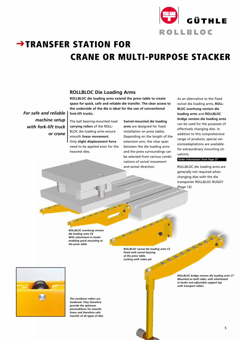
ROLLBLOC overhung version die loading arms CK With attachment in hooks enabling quick mounting at the press table
ROLLBLOC swivel die loading arms CSFixed with swivel bearing at the press table. Locking with index pin
ROLLBLOC bridge version die loading arms CTMounted on both sides, with attachment in hooks and adjustable support leg with transport rollers
The cantilever rollers are hardened. They therefore provide the optimum preconditions for smooth, linear and therefore safe transfer of all types of dies
For safe and reliable
machine setup
with fork-lift truck
or crane
ROLLBLOC Die Loading ArmsROLLBLOC die loading arms extend the press table to create
space for quick, safe and reliable die transfer. The clear access to
the underside of the die is ideal for the use of conventional
fork-lift trucks.
The ball bearing-mounted load
carrying rollers of the ROLL-
BLOC die loading arms ensure
smooth linear movement.
Only slight displacement force
need to be applied even for the
heaviest dies.
Swivel-mounted die loading
arms are designed for fixed
installation on press tables.
Depending on the length of the
extension arm, the clear span
between the die loading arms
and the press surroundings can
be selected from various combi-
nations of swivel movement
and swivel direction.
CTRANSFER STATION FOR CRANE OR MULTI-PURPOSE STACKER
5
As an alternative to the fixed
swivel die loading arms, ROLL-
BLOC overhung version die
loading arms and ROLLBLOC
bridge version die loading arms
can be used for the purposes of
effectively changing dies. In
addition to this comprehensive
range of products, special ver-
sions/adaptations are available
for extra ordinary mounting sit-
uations.
Order information from Page 27
ROLLBLOC die loading arms are
generally not required when
changing dies with the die
trans por ter ROLLBLOC BUGGY
(Page 12).
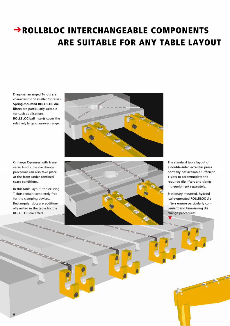
The standard table layout of
a double-sided eccentric press
normally has available sufficient
T-slots to accommodate the
required die lifters and clamp-
ing equipment separately.
Stationary mounted, hydraul-
ically-operated ROLLBLOC die
lifters ensure particularly con-
venient and time-saving die
change procedures.
N
CROLLBLOC INTERCHANGEABLE COMPONENTS ARE SUITABLE FOR ANY TABLE LAYOUT
Diagonal arranged T-slots are
characteristic of smaller C-presses.
Spring-mounted ROLLBLOC die
lifters are particularly suitable
for such applications.
ROLLBLOC ball inserts cover the
relatively large cross-over range.
On large C-presses with trans-
verse T-slots, the die change
procedure can also take place
at the front under confined
space conditions.
In this table layout, the existing
T-slots remain completely free
for the clamping devices.
Rectangular slots are addition-
ally milled in the table for the
ROLLBLOC die lifters.
6
Breite: 65 mmStrichstärke: 0,3mmGröße wie Katalog
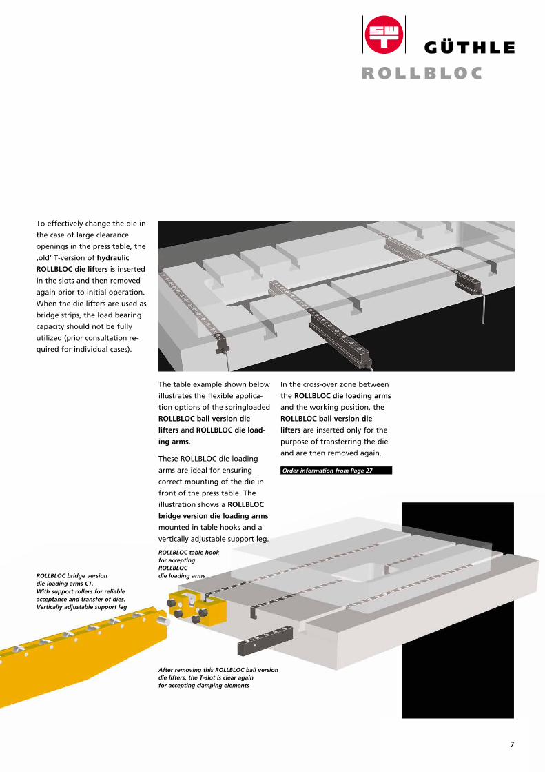
To effectively change the die in
the case of large clearance
open ings in the press table, the
‚old‘ T-version of hydraulic
ROLLBLOC die lifters is inserted
in the slots and then removed
again prior to initial operation.
When the die lifters are used as
bridge strips, the load bearing
capacity should not be fully
utilized (prior consultation re-
quired for individual cases).
In the cross-over zone between
the ROLLBLOC die loading arms
and the working position, the
ROLLBLOC ball version die
lifters are inserted only for the
purpose of transferring the die
and are then removed again.
Order information from Page 27
After removing this ROLLBLOC ball version die lifters, the T-slot is clear again for accepting clamping elements
ROLLBLOC bridge version die loading arms CT.With support rollers for reliable acceptance and transfer of dies. Vertically adjustable support leg
ROLLBLOC table hook for accepting ROLLBLOC die loading arms
The table example shown below
illustrates the flexible applica-
tion options of the springloaded
ROLLBLOC ball version die
lifters and ROLLBLOC die load-
ing arms.
These ROLLBLOC die loading
arms are ideal for ensuring
correct mount ing of the die in
front of the press table. The
illustration shows a ROLLBLOC
bridge version die loading arms
mounted in table hooks and a
vertically ad just able support leg.
7
Adaptive ROLLBLOC hydraulic
quick-action clamps offer not
only practical convenience for
frequent die change procedures
but also tangible economic
benefits with regard to setup
times and die protection.
Also suitable for combinationsThe different types of ROLLBLOC
hydraulic quick-action clamps
can be used in combined
arrangements.
(Example: ROLLBLOC ledge
clamps on the press table,
ROLLBLOC Wedge Clamps on
the ram)
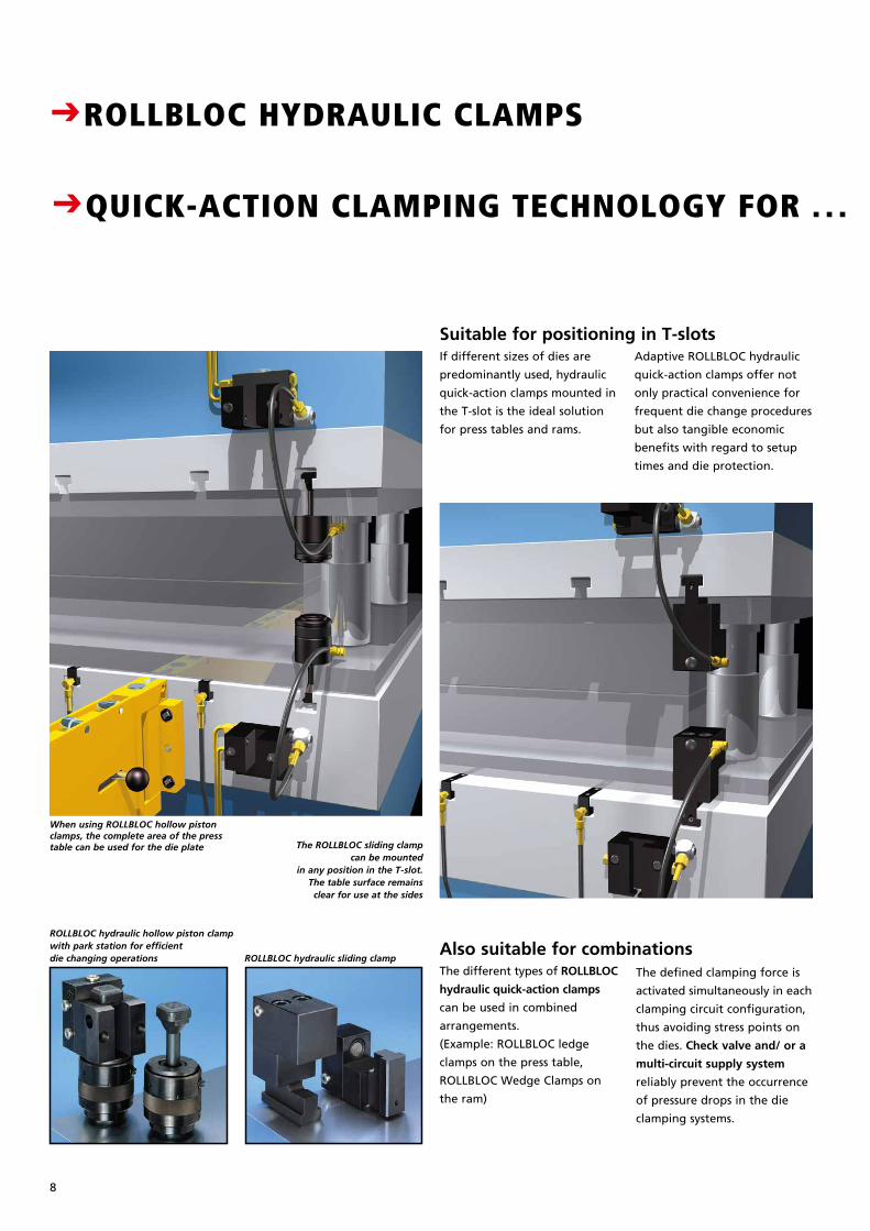
When using ROLLBLOC hollow piston clamps, the complete area of the press table can be used for the die plate
ROLLBLOC hydraulic hollow piston clampwith park station for efficient die changing operations ROLLBLOC hydraulic sliding clamp
The ROLLBLOC sliding clamp can be mounted
in any position in the T-slot. The table surface remains clear for use at the sides
CROLLBLOC HYDRAULIC CLAMPS CQUICK-ACTION CLAMPING TECHNOLOGY FOR . . . PRESS TABLE AND RAM
If different sizes of dies are
predominantly used, hydraulic
quick-action clamps mounted in
the T-slot is the ideal solution
for press tables and rams.
Suitable for positioning in T-slots
The defined clamping force is
activated simultaneously in each
clamping circuit configuration,
thus avoiding stress points on
the dies. Check valve and/ or a
multi-circuit supply system
reliably prevent the occurrence
of pressure drops in the die
clamp ing systems.
8
Breite: 65 mmStrichstärke: 0,3mmGröße wie Katalog
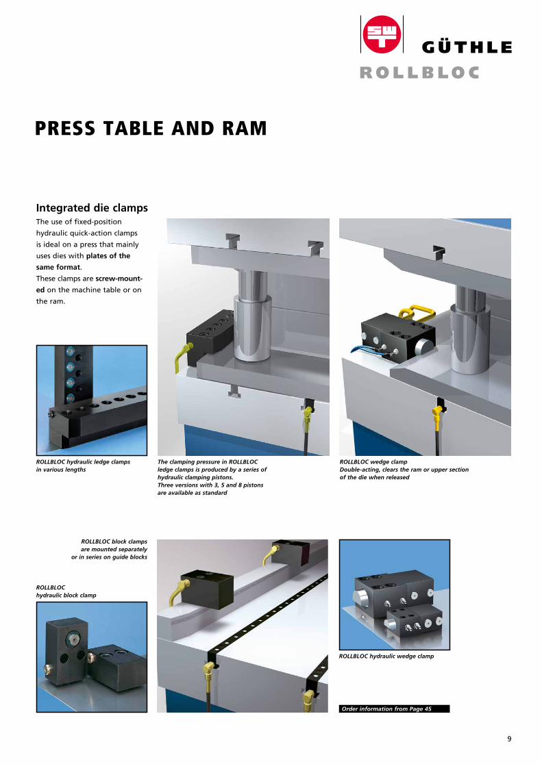
The clamping pressure in ROLLBLOC ledge clamps is produced by a series of hydraulic clamping pistons. Three versions with 3, 5 and 8 pistons are available as standard
ROLLBLOC hydraulic ledge clampsin various lengths
ROLLBLOC hydraulic block clamp
ROLLBLOC block clamps are mounted separately
or in series on guide blocks
ROLLBLOC hydraulic wedge clamp
The use of fixed-position
hy drau lic quick-action clamps
is ideal on a press that mainly
uses dies with plates of the
same format.
These clamps are screw-mount-
ed on the machine table or on
the ram.
ROLLBLOC wedge clamp Double-acting, clears the ram or upper section of the die when released
Integrated die clamps
Order information from Page 45
CROLLBLOC HYDRAULIC CLAMPS CQUICK-ACTION CLAMPING TECHNOLOGY FOR . . . PRESS TABLE AND RAM
9
10
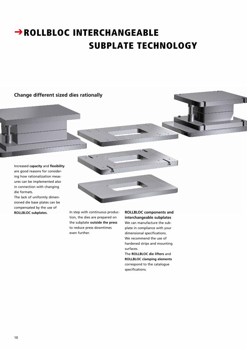
In step with continuous produc-
tion, the dies are prepared on
the subplate outside the press
to reduce press downtimes
even further.
ROLLBLOC components and interchangeable subplatesWe can manufacture the sub-
plate in compliance with your
dimensional speci fi cat ions.
We recommend the use of
hard ened strips and mounting
surfaces.
The ROLLBLOC die lifters and
ROLLBLOC clamping elements
correspond to the catalogue
specifications.
Change different sized dies rationally
Increased capacity and flexibility
are good reasons for consider-
ing how rationalization meas-
ures can be implemented also
in connection with changing
die formats.
The lack of uniformly dimen -
s ioned die base plates can be
compensated by the use of
ROLLBLOC subplates.
CROLLBLOC INTERCHANGEABLE SUBPLATE TECHNOLOGY CTHE DIES ARE SET UP
ALREADY BEFORE THE CHANGE
Breite: 65 mmStrichstärke: 0,3mmGröße wie Katalog
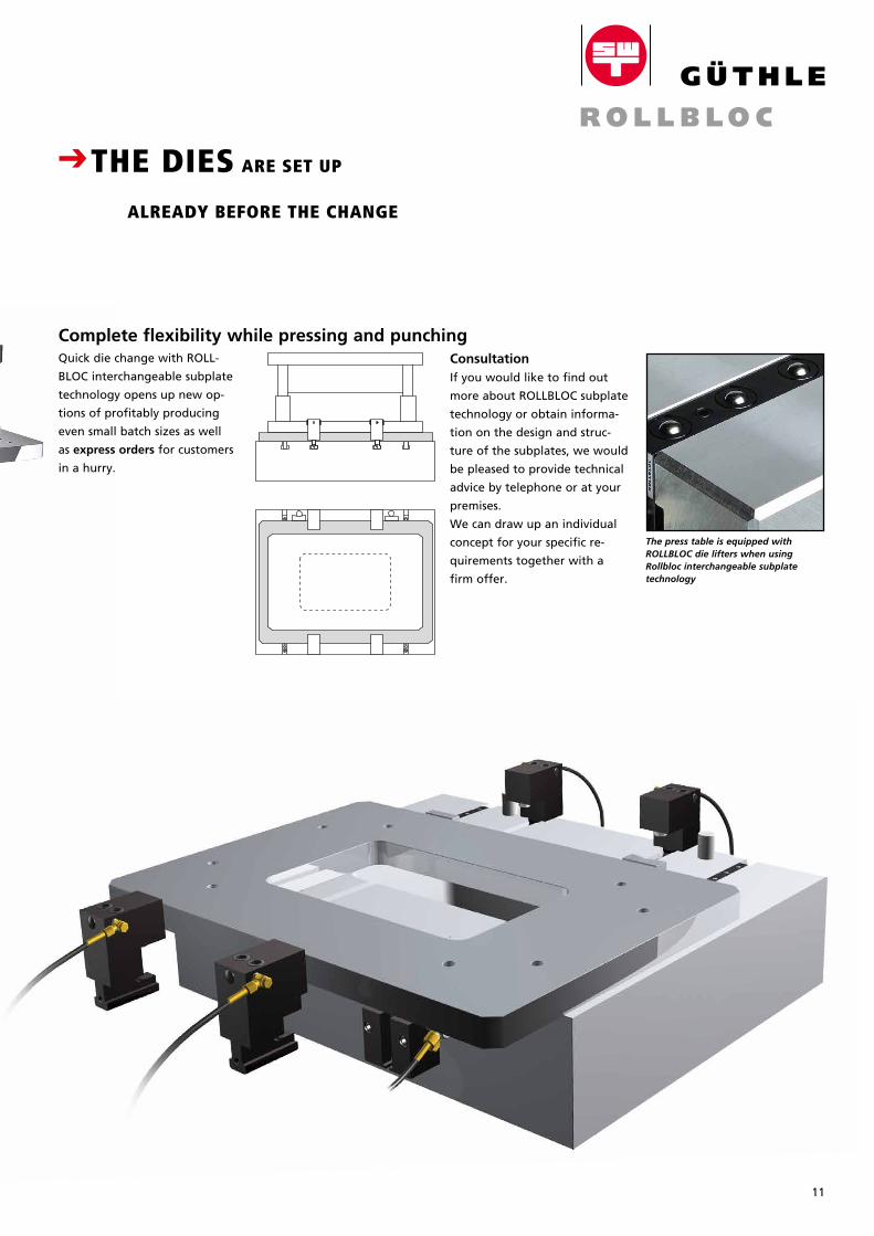
11
The press table is equipped with ROLLBLOC die lifters when using Rollbloc interchangeable subplate technology
CROLLBLOC INTERCHANGEABLE SUBPLATE TECHNOLOGY CTHE DIES ARE SET UP
ALREADY BEFORE THE CHANGE
Quick die change with ROLL-
BLOC interchangeable subplate
technology opens up new op-
tions of profitably producing
even small batch sizes as well
as express orders for customers
in a hurry.
Complete flexibility while pressing and punchingConsultationIf you would like to find out
more about ROLLBLOC subplate
technology or obtain informa-
tion on the design and struc-
ture of the subplates, we would
be pleased to provide technical
advice by telephone or at your
premises.
We can draw up an individual
concept for your specific re-
quire ments together with a
firm offer.
12
1600
105
750
300
1570
700
2060
350/
650
1650
860
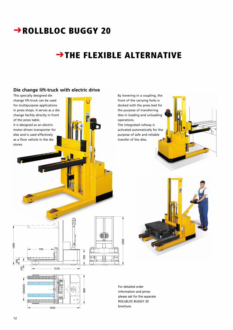
CROLLBLOC BUGGY 20 CTHE FLEXIBLE ALTERNATIVE
Die change lift-truck with electric drive
For detailed order
information and prices
please ask for the separate
ROLLBLOC BUGGY 20
brochure.
This specially designed die
change lift-truck can be used
for multipurpose applications
in press shops. It serves as a die
change facility directly in front
of the press table.
It is designed as an electric
motor-driven transporter for
dies and is used effectively
as a floor vehicle in the die
stores.
By lowering in a coupling, the
front of the carrying forks is
docked with the press bed for
the purpose of transferring
dies in loading and unloading
operations.
The integrated rollway is
activated automatically for the
purpose of safe and reliable
transfer of the dies.
Breite: 65 mmStrichstärke: 0,3mmGröße wie Katalog
13
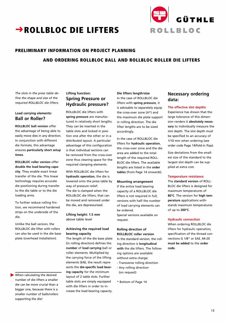
The slots in the press table de-
fine the shape and size of the
required ROLLBLOC die lifters.
Load carrying elements:
Ball or Roller?
ROLLBLOC ball version offer
the advantage of being able to
easily move dies in any direction.
In conjunction with different
die formats, this advantage
ensures particularly short setup
times.
ROLLBLOC roller version offer
double the load bearing capa-
city. They enable exact linear
transfer of the die. This linear
technology requires accurate
die positioning during transfer
to the die table or to the die
loading arms.
To further reduce rolling fric-
tion, we recommend hardened
strips on the underside of the
die.
Unlike the ball version, the
ROLLBLOC die lifter with rollers
can also be used in the die base
plate (overhead installation).
When calculating the desired
number of die lifters a smaller
die can be more crucial than a
bigger one, because there is a
smaller number of balls/rollers
supporting the die!
Necessary ordering data:
The effective slot depths
Experience has shown that the
large tolerance of this dimen-
sion renders it absolutely neces-
sary to individually measure the
slot depth. The slot depth must
be specified to an accuracy of
1/10 mm when ordering (see
order code Page 14/fold-in flap).
Size deviations from the small-
est size of the standard to the
larg est slot depth can be sup-
plied at extra cost.
Temperature resistance
The standard version of ROLL-
BLOC die lifters is designed for
maximum temperatures of
80°C. The version for high tem-
perature applications with-
stands maximum temperatures
of up to 200°C.
Hydraulic connection
When ordering ROLLBLOC die
lifters for hydraulic operation,
specification of the thread con-
nections G 1/8“ or SAE_44-20
must be added to the order
code.
Die lifters length/size
In the case of ROLLBLOC die
lifters with spring pressure, it
is advisable to separately equip
the cross-over zone (A*) and
the maximum die plate support
in rolling direction. The die
lifter lengths are to be sized
accordingly.
In the case of ROLLBLOC die
lifters for hydraulic operation,
the cross-over zone and the die
area are added to the total
length of the required ROLL-
BLOC die lifters. The available
lengths are listed in the order
tables (from Page 14 onwards).
Mounting arrangement
If the entire load bearing
ca pac ity of a ROLLBLOC die
lifters is not required in full,
vers ions with half the number
of load carrying elements can
be ordered.
Special versions available on
request.
Rolling direction of
ROLLBLOC roller version
In the standard version, the roll -
ing direction is longitudinal
with the die lifters. The follow-
ing opt ions are available
without extra charge:
- Transverse rolling direction
- Any rolling direction
(on request)
* Bottom of Page 14
Lifting function:
Spring Pressure or Hydraulic pressure?
ROLLBLOC die lifters with
spring pressure are manufac-
tured in relatively short lengths.
They can be inserted in the
table slots and locked in posi-
tion one after the other or in a
distributed layout. A particular
advantage of this configuration
is that individual sections can
be removed from the cross-over
zone thus clearing space for the
required clamping elements.
With ROLLBLOC die lifters for
hydraulic operation, the die is
lowered onto the press table by
way of pressure relief.
The die is clamped when the
ROLLBLOC die lifters, that can
be moved and removed under
the die, are depressurised.
Lifting height: 1.5 mm
above table level
Achieving the required load
bearing capacity
The length of the die base plate
(in rolling direction) defines the
number of load carrying ball or
roller elements. Multiplied by
the carrying force of the lifting
elements (kN), the result repre-
sents the die-specific load bear-
ing capacity for the minimum
layout of 2 table slots. Further
table slots are simply equipped
with die lifters in order to in-
crease the load bearing capacity.
CROLLBLOC DIE LIFTERS
PRELIMINARY INFORMATION ON PROJECT PLANNING
AND ORDERING ROLLBLOC BALL AND ROLLBLOC ROLLER DIE LIFTERS
P
Breite: 65 mmStrichstärke: 0,3mmGröße wie Katalog
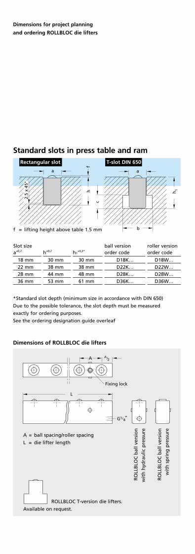
Standard slots in press table and ram
roller versionorder code
D18W...D22W...D28W...D36W...
Slot sizea+0,2
18 mm 22 mm 28 mm 36 mm
h+0,2
30 mm 38 mm 44 mm 53 mm
h1+0,2*
30 mm 38 mm 48 mm 61 mm
ball versionorder code
D18K...D22K...D28K...D36K...
*Standard slot depth (minimum size in accordance with DIN 650)
Due to the possible tolerance, the slot depth must be measured
exactly for ordering purposes.
See the ordering designation guide overleaf
f
2.5
x 45
°
b
c
hh
a
a
f
2.5
x 45
°
b
c
hh
a
a
Rectangular slot T-slot DIN 650
ROLLBLOC T-version die lifters.
Available on request.
A = ball spacing/roller spacing
L = die lifter length
A/2A
L
G1/8“
Fixing lock
A2/
H
18/G
L N
A
ff
Dimensions of ROLLBLOC die lifters
1
Dimensions for project planning
and ordering ROLLBLOC die lifters
RO
LLB
LOC
bal
l ve
rsio
n
wit
h h
ydra
ulic
pre
ssu
re
RO
LLB
LOC
bal
l ve
rsio
n
wit
h s
pri
ng
pre
ssu
re
f = lifting height above table 1.5 mm
The guide
to simple and exact
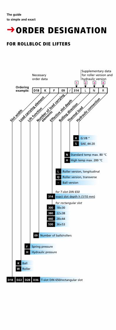
CORDER DESIGNATIONFOR ROLLBLOC DIE LIFTERS
Slot w
idth
Load
carry
ing e
lem
ent
Lift f
unctio
n
Number
of l
oad ca
rryin
g
el
emen
ts
Effe
ctiv
e slo
t dep
th
Ther
mal
load
K F 09 / 314 L RN
Hydra
ulic co
nnectio
n
M
2
M
1
M
3
M
4
09 Number of balls/rollers
F Spring pressure
H Hydraulic pressure
K Ball
W Roller
D18 D22 D28 D36 T-slot DIN 650/rectangular slot
Rolling d
irect
ion
for T-slot DIN 650
Necessary order data
Supplementary data for roller version and hydraulic version
R G 1/8 ”
S SAE_44-20
314 exact slot depth h (1/10 mm)
for rectangular slot
300 18x30
380 22x38
440 28x44
530 36x53
L Roller version, longitudinal
Q Roller version, transverse
– Ball version
N Standard temp max. 80 °C
H High temp max. 200 °C
Ordering example: D18
14
Supplementary data for roller version and hydraulic version
Ordercode
D18WF03 / 300 L ND18WF04 / . . . L ND18WF05 / . . . L ND18WF06 / . . . L ND18WF08 / . . . L ND18WF10 / . . . L N
3
Lifterlength
105 mm 140 mm 175 mm 210 mm 280 mm 350 mm
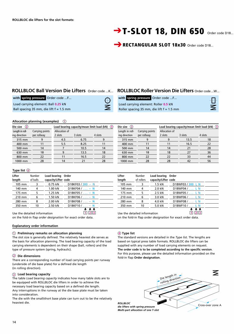
ROLLBLOC die lifters for the slot formats:
Load carrying element: Ball 0.25 kN
Ball spacing 35 mm, die lift f = 1.5 mm
Load carrying element: Roller 0.5 kN
Roller spacing 35 mm, die lift f = 1.5 mm
Type list 4
1
3
Explanatory order information
4
2
3
1 Preliminary remarks on allocation planningThe slot size is generally defined. The relatively heaviest die serves as the basis for allocation planning. The load bearing capacity of the load carrying elements is dependent on their shape (ball, rollers) and the type of pressure system (spring, hydraulic).
Die dimensionsThere are a corresponding number of load carrying points per runway (underside of die base plate) for a defined die length (in rolling direction).
Load bearing capacityThe table Load bearing capacity indicates how many table slots are to be equipped with ROLLBLOC die lifters in order to achieve the necessary load bearing capacity based on a defined die length. Any interruptions in the runway at the die base plate must be taken into consideration.The die with the small/short base plate can turn out to be the relatively heaviest die.
Type listThe standard versions are detailed in the Type list. The lengths are based on typical press table formats. ROLLBLOC die lifters can be supplied with any number of load carrying elements on request.The order code is to be completed according to the specific version. For this purpose, please use the detailed information provided on the fold-in flap Order designation.
Use the detailed information on the fold-in flap order designation for exact order data.
Use the detailed information on the fold-in flap order designation for exact order data.
M
1
M
2
M
3
Load bearingcapacity/Lifter
0.75 kN1.00 kN1.25 kN1.50 kN2.00 kN2.50 kN
Numberof balls
3456810
Ordercode
D18KF03 / 300 – ND18KF04 / . . . – ND18KF05 / . . . – ND18KF06 / . . . – ND18KF08 / . . . – ND18KF10 / . . . – N
PreisDM
121.–145.–195.–230.–260.–300.–
Lifterlength
105 mm140 mm175 mm210 mm280 mm350 mm
Load bearingcapacity/Lifter
1.5 kN2.0 kN2.5 kN3.0 kN4.0 kN5.0 kN
Numberof rollers
3456810
PreisDM
121.–145.–195.–230.–260.–300.–
Carrying points per rollway
91114182228
4 slots
91114182228
Carrying points per rollway
91114182228
2 slots
91114182228
3 slots
13.516.521273342
4 slots
182228364456
ROLLBLOC Roller Version Die Lifters Order code ...W... with spring pressure Order code ...F...
ROLLBLOC Ball Version Die Lifters Order code ...K...
with spring pressure Order code ...F...
3 slots
6.758.2510.513.516.521
2 slots
4.55.579
1114
Length in roll - ing direction
315 mm 400 mm 500 mm 630 mm 800 mm 1000 mm
Length in roll- ing direction
315 mm 400 mm 500 mm 630 mm 800 mm 1000 mm
Load bearing capacity/mean limit load (kN) Allocation of
2Die size Load bearing capacity/mean limit load (kN) Allocation of
Die length in
rolling direction
Cross-over zone AROLLBLOC die lifters with spring pressure Multi-part allocation of one T-slot
CT-SLOT 18, DIN 650 Order code D18...
CRECTANGULAR SLOT 18x30 Order code D18...
Allocation planning (examples)
2Die size
M
1
M
2
M
3
15
Breite: 65 mmStrichstärke: 0,3mmGröße wie Katalog
Ordercode
D18WH07 / 300 L N R D18WH09 / . . . L N R D18WH11 / . . . L N R D18WH14 / . . . L N R D18WH16 / . . . L N R D18WH18 / . . . L N RD18WH20 / . . . L N R D18WH22 / . . . L N R D18WH25 / . . . L N R D18WH28 / . . . L N RD18WH31 / . . . L N R D18WH35 / . . . L N R D18WH40 / . . . L N R
Ordercode
D18KH07 / 300 – N RD18KH09 / . . . – N R D18KH11 / . . . – N RD18KH14 / . . . – N RD18KH16 / . . . – N RD18KH18 / . . . – N RD18KH20 / . . . – N RD18KH22 / . . . – N RD18KH25 / . . . – N RD18KH28 / . . . – N RD18KH31 / . . . – N RD18KH35 / . . . – N RD18KH40 / . . . – N R
Lifterlength
245 mm 315 mm 385 mm 490 mm 560 mm 630 mm 700 mm 770 mm 875 mm 980 mm 1085 mm 1225 mm 1400 mm
Lifterlength
245 mm 315 mm 385 mm 490 mm 560 mm 630 mm 700 mm 770 mm 875 mm 980 mm 1085 mm 1225 mm 1400 mm
2
See opposite page for
Explanatory order information
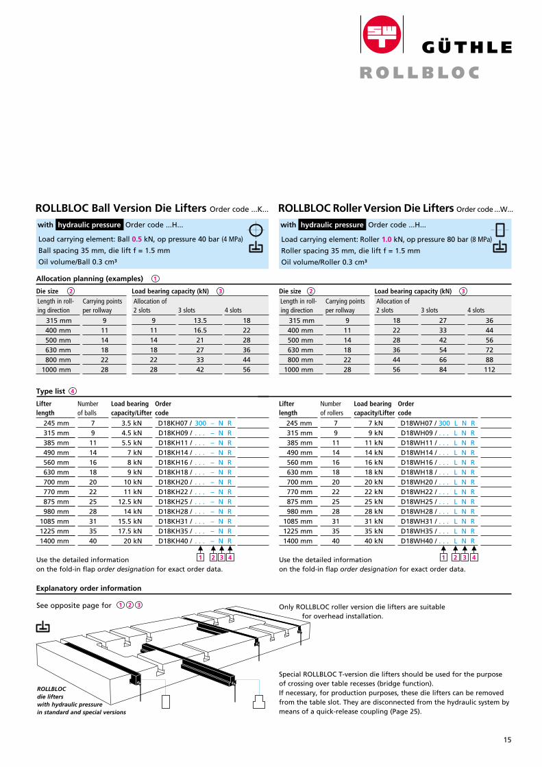
Special ROLLBLOC T-version die lifters should be used for the purpose of crossing over table recesses (bridge function). If necessary, for production purposes, these die lifters can be removed from the table slot. They are disconnected from the hydraulic system by means of a quick-release coupling (Page 25).
Only ROLLBLOC roller version die lifters are suitable for overhead installation.
3
Use the detailed information on the fold-in flap order designation for exact order data.
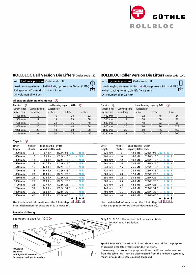
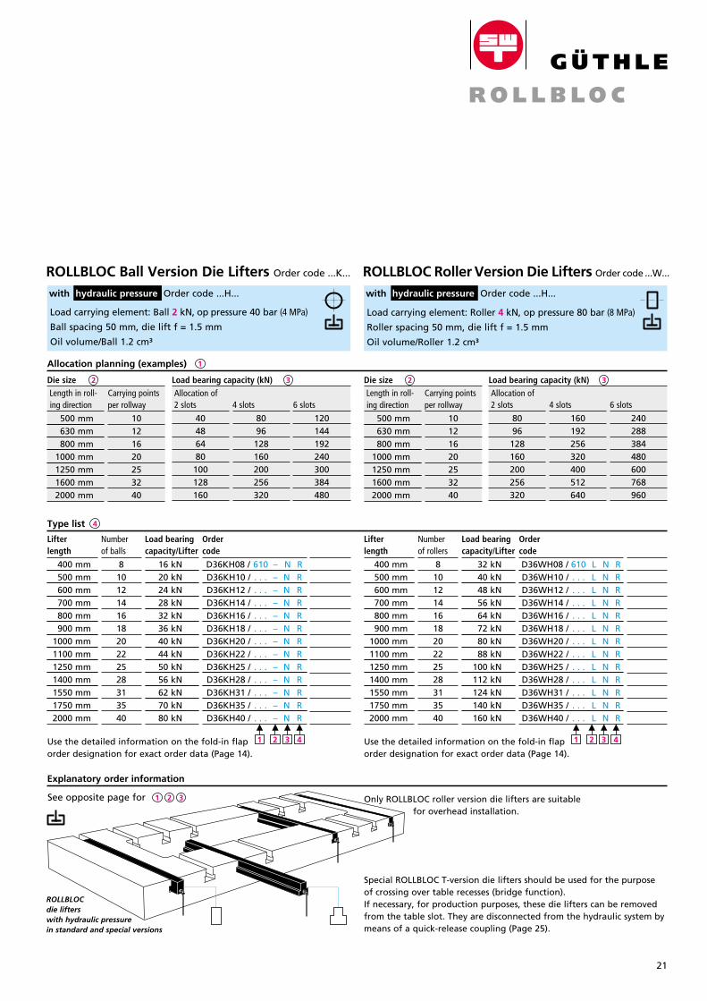
Load carrying element: Ball 0.5 kN, op pressure 40 bar (4 MPa)
Ball spacing 35 mm, die lift f = 1.5 mm
Oil volume/Ball 0.3 cm³
Load carrying element: Roller 1.0 kN, op pressure 80 bar (8 MPa)
Roller spacing 35 mm, die lift f = 1.5 mm
Oil volume/Roller 0.3 cm³
Load bearingcapacity/Lifter
3.5 kN 4.5 kN 5.5 kN 7 kN 8 kN 9 kN 10 kN 11 kN 12.5 kN 14 kN 15.5 kN 17.5 kN 20 kN
Numberof balls
791114161820222528313540
PreisDM
121.–145.–195.–230.–260.–300.–350.–400.–121.–145.–
Type list 4
Load bearingcapacity/Lifter
7 kN 9 kN 11 kN 14 kN 16 kN 18 kN 20 kN 22 kN 25 kN 28 kN 31 kN 35 kN 40 kN
Numberof rollers
791114161820222528313540
PreisDM
121.–145.–195.–230.–260.–300.–350.–400.–121.–145.–
Length in roll- ing direction
315 mm 400 mm 500 mm 630 mm 800 mm 1000 mm
Carrying points per rollway
91114182228
1
Load bearing capacity (kN) Allocation of
Die size 3Load bearing capacity (kN) Allocation of Length in roll-
ing direction
315 mm 400 mm 500 mm 630 mm 800 mm 1000 mm
Carrying points per rollway
91114182228
2 slots
182228364456
4 slots
3644567288
112
3 slots
273342546684
M
2
M
1
M
3
M
4
M
2
M
1
M
3
M
4 Use the detailed information on the fold-in flap order designation for exact order data.
ROLLBLOC Roller Version Die Lifters Order code ...W... with hydraulic pressure Order code ...H...
ROLLBLOC Ball Version Die Lifters Order code ...K...
with hydraulic pressure Order code ...H...
4 slots
182228364456
3 slots
13.516.521273342
2 slots
91114182228
ROLLBLOCdie lifterswith hydraulic pressure in standard and special versions
Allocation planning (examples)
2Die size
1 2 3
16
2
Lifterlength
120 mm 160 mm 200 mm 240 mm 320 mm 400 mm
Lifterlength
120 mm 160 mm 200 mm 240 mm 320 mm 400 mm
ROLLBLOC die lifters for the slot formats:
Type list 4
1
33
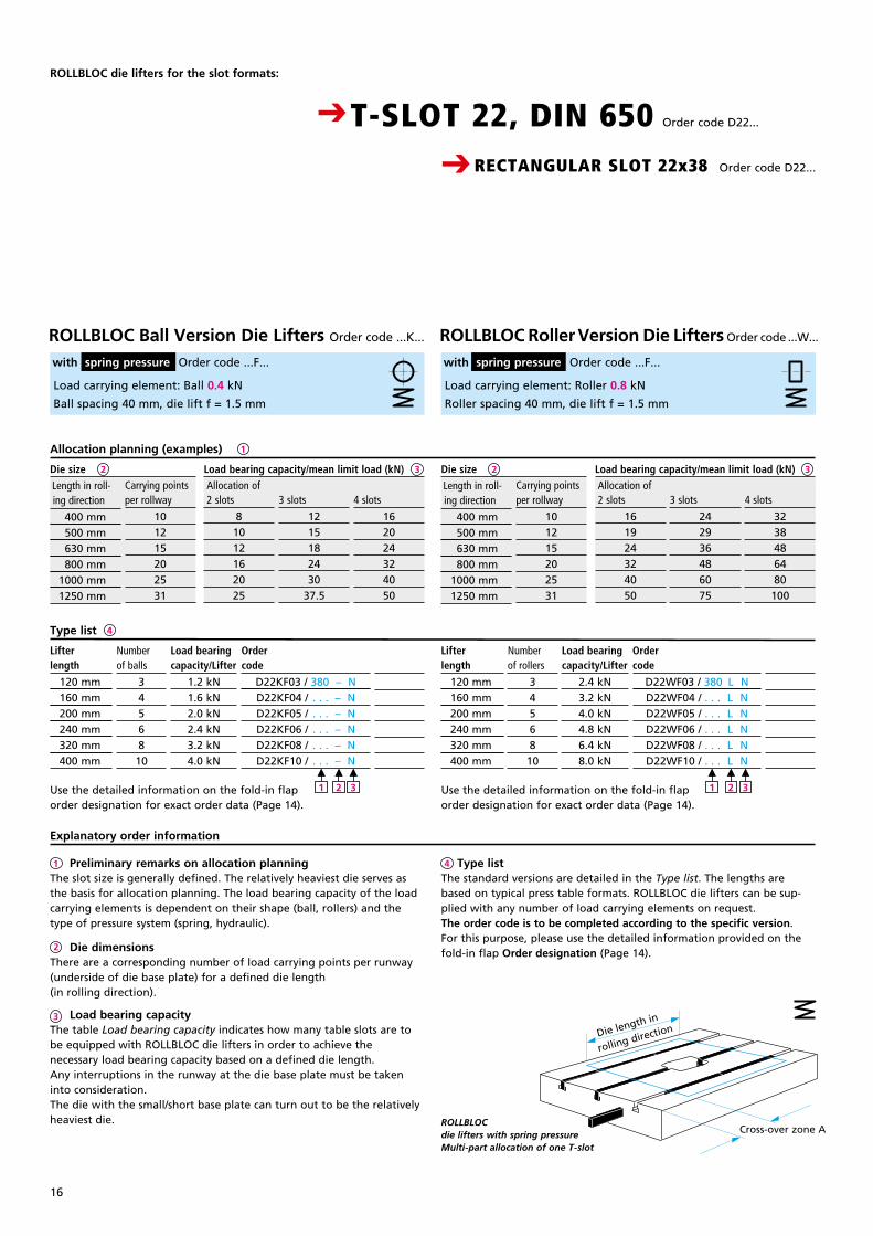
Load carrying element: Ball 0.4 kN
Ball spacing 40 mm, die lift f = 1.5 mm
Load carrying element: Roller 0.8 kN
Roller spacing 40 mm, die lift f = 1.5 mm
Load bearingcapacity/Lifter
1.2 kN1.6 kN2.0 kN2.4 kN3.2 kN4.0 kN
Numberof balls
3456810
Ordercode
D22KF03 / 380 – ND22KF04 / . . . – ND22KF05 / . . . – ND22KF06 / . . . – ND22KF08 / . . . – ND22KF10 / . . . – N
PreisDM
121.–145.–195.–230.–260.–300.–
Load bearingcapacity/Lifter
2.4 kN3.2 kN4.0 kN4.8 kN6.4 kN8.0 kN
Numberof rollers
3456810
Ordercode
D22WF03 / 380 L ND22WF04 / . . . L ND22WF05 / . . . L ND22WF06 / . . . L ND22WF08 / . . . L ND22WF10 / . . . L N
PreisDM
121.–145.–195.–230.–260.–300.–
Length in roll- ing direction
400 mm 500 mm 630 mm 800 mm 1000 mm 1250 mm
Carrying points per rollway
101215202531
Carrying points per rollway
101215202531
2 slots
161924324050
3 slots
242936486075
4 slots
3238486480
100
Use the detailed information on the fold-in flap order designation for exact order data (Page 14).
Use the detailed information on the fold-in flap order designation for exact order data (Page 14).
Preliminary remarks on allocation planningThe slot size is generally defined. The relatively heaviest die serves as the basis for allocation planning. The load bearing capacity of the load carrying elements is dependent on their shape (ball, rollers) and the type of pressure system (spring, hydraulic).
Die dimensionsThere are a corresponding number of load carrying points per runway (underside of die base plate) for a defined die length (in rolling direction).
Load bearing capacityThe table Load bearing capacity indicates how many table slots are to be equipped with ROLLBLOC die lifters in order to achieve the necessary load bearing capacity based on a defined die length. Any interruptions in the runway at the die base plate must be taken into consideration.The die with the small/short base plate can turn out to be the relatively heaviest die.
Explanatory order information
4
2
3
1
M
1
M
2
M
3
M
1
M
2
M
3
CRECTANGULAR SLOT 22x38 Order code D22...
CT-SLOT 22, DIN 650 Order code D22...
4 slots
162024324050
3 slots
1215182430
37.5
2 slots
81012162025
Load bearing capacity/mean limit load (kN) Allocation of
Load bearing capacity/mean limit load (kN) Allocation of Length in roll-
ing direction
400 mm 500 mm 630 mm 800 mm 1000 mm 1250 mm
2Die size Die size
Type listThe standard versions are detailed in the Type list. The lengths are based on typical press table formats. ROLLBLOC die lifters can be sup-plied with any number of load carrying elements on request.The order code is to be completed according to the specific version. For this purpose, please use the detailed information provided on the fold-in flap Order designation (Page 14).
Die length in
rolling direction
Cross-over zone AROLLBLOC die lifters with spring pressure Multi-part allocation of one T-slot
Allocation planning (examples)
ROLLBLOC Roller Version Die Lifters Order code ...W... with spring pressure Order code ...F...
ROLLBLOC Ball Version Die Lifters Order code ...K...
with spring pressure Order code ...F...
17
Breite: 65 mmStrichstärke: 0,3mmGröße wie Katalog
2 32 3
Lifterlength
320 mm 400 mm 480 mm 560 mm 640 mm 720 mm 800 mm 880 mm 1000 mm 1120 mm 1240 mm 1400 mm 1600 mm
Lifterlength
320 mm 400 mm 480 mm 560 mm 640 mm 720 mm 800 mm 880 mm 1000 mm 1120 mm 1240 mm 1400 mm 1600 mm
Use the detailed information on the fold-in flap order designation for exact order data (Page 14).
Use the detailed information on the fold-in flap order designation for exact order data (Page 14).
Load carrying element: Ball 0.8 kN, op pressure 40 bar (4 MPa)
Ball spacing 40 mm, die lift f = 1.5 mm
Oil volume/Ball 0.5 cm³
Load carrying element: Roller 1.6 kN, op pressure 80 bar (8 MPa)
Roller spacing 40 mm, die lift f = 1.5 mm
Oil volume/Roller 0.5 cm³
Load bearingcapacity/Lifter
6.4 kN 8.0 kN 9.6 kN 11.2 kN 12.8 kN 14.4 kN 16.0 kN 17.6 kN 20.0 kN 22.4 kN 24.8 kN 28.0 kN 32.0 kN
Numberof balls
8101214161820222528313540
Ordercode
D22KH08 / 380 – N R D22KH10 / . . . – N RD22KH12 / . . . – N RD22KH14 / . . . – N RD22KH16 / . . . – N R D22KH18 / . . . – N RD22KH20 / . . . – N RD22KH22 / . . . – N RD22KH25 / . . . – N R D22KH28 / . . . – N RD22KH31 / . . . – N R D22KH35 / . . . – N R D22KH40 / . . . – N R
PreisDM
121.–145.–195.–230.–260.–300.–350.–400.–121.–145.–
Type list 4
Load bearingcapacity/Lifter
12.8 kN16.0 kN19.2 kN22.4 kN25.6 kN28.8 kN32.0 kN35.2 kN40.0 kN44.8 kN49.6 kN56.0 kN64.0 kN
Numberof rollers
8101214161820222528313540
Ordercode
D22WH08 / 380 L N R D22WH10 / . . . L N R D22WH12 / . . . L N R D22WH14 / . . . L N R D22WH16 / . . . L N R D22WH18 / . . . L N R D22WH20 / . . . L N RD22WH22 / . . . L N RD22WH25 / . . . L N R D22WH28 / . . . L N RD22WH31 / . . . L N R D22WH35 / . . . L N R D22WH40 / . . . L N R
PreisDM
121.–145.–195.–230.–260.–300.–350.–400.–121.–145.–
Carrying points per rollway
101215202531
1
Load bearing capacity (kN) Allocation of Carrying points
per rollway
101215202531
2 slots
3238486480100
4 slots
647696
128160200
Load bearing capacity (kN) Allocation of
3 slots
48587296120150
M
2
M
1
M
3
M
4
M
2
M
1
M
3
M
4
4 slots
3238486480100
3 slots
242936486075
2 slots
161924324050
Length in roll- ing direction
400 mm 500 mm 630 mm 800 mm 1000 mm 1250 mm
Length in roll- ing direction
400 mm 500 mm 630 mm 800 mm 1000 mm 1250 mm
Bestellvorklärung
CRECTANGULAR SLOT 22x38 Order code D22...
CT-SLOT 22, DIN 650 Order code D22...
Die size Die size
ROLLBLOCdie lifterswith hydraulic pressure in standard and special versions
Allocation planning (examples)
See opposite page for
Special ROLLBLOC T-version die lifters should be used for the purpose of crossing over table recesses (bridge function). If necessary, for production purposes, these die lifters can be removed from the table slot. They are disconnected from the hydraulic system by means of a quick-release coupling (Page 25).
1 2 3 Only ROLLBLOC roller version die lifters are suitable for overhead installation.
ROLLBLOC Roller Version Die Lifters Order code ...W... with hydraulic pressure Order code ...H...
ROLLBLOC Ball Version Die Lifters Order code ...K...
with hydraulic pressure Order code ...H...
18
1
Lifterlength
135 mm 180 mm 225 mm 270 mm 360 mm 450 mm
2
ROLLBLOC die lifters for the slot formats:
Type list 4
Allocation planning (examples)
33
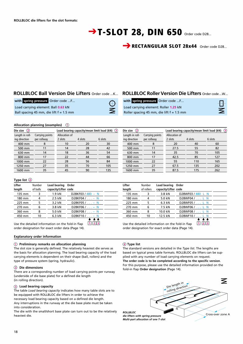
Load carrying element: Ball 0.63 kN
Ball spacing 45 mm, die lift f = 1.5 mm
Load carrying element: Roller 1.25 kN
Roller spacing 45 mm, die lift f = 1.5 mm
Carrying points per rollway
8111417222735
2 slots
10141822283545
6 slots
3042546684105135
Carrying points per rollway
8111417222735
2 slots
2027.535
42.555
67.587.5
4 slots
40557085110135175
6 slots
6082
105127165202262
4 slots
20283644567090
Lifterlength
135 mm 180 mm 225 mm 270 mm 360 mm 450 mm
Load bearingcapacity/Lifter
1.9 kN2.5 kN3.2 kN3.8 kN5.0 kN6.3 kN
Numberof balls
3456810
Ordercode
D28KF03 / 480 – ND28KF04 / . . . – ND28KF05 / . . . – ND28KF06 / . . . – ND28KF08 / . . . – ND28KF10 / . . . – N
PreisDM
121.–145.–195.–230.–260.–300.–
Load bearingcapacity/Lifter
3.8 kN 5.0 kN 6.3 kN 7.5 kN 10.0 kN 12.5 kN
Numberof rollers
3456810
Ordercode
D28WF03 / 480 L ND28WF04 / . . . L ND28WF05 / . . . L ND28WF06 / . . . L ND28WF08 / . . . L ND28WF10 / . . . L N
PreisDM
121.–145.–195.–230.–260.–300.–
Use the detailed information on the fold-in flap order designation for exact order data (Page 14).
Use the detailed information on the fold-in flap order designation for exact order data (Page 14).
Preliminary remarks on allocation planningThe slot size is generally defined. The relatively heaviest die serves as the basis for allocation planning. The load bearing capacity of the load carrying elements is dependent on their shape (ball, rollers) and the type of pressure system (spring, hydraulic).
Die dimensionsThere are a corresponding number of load carrying points per runway (underside of die base plate) for a defined die length (in rolling direction).
Load bearing capacityThe table Load bearing capacity indicates how many table slots are to be equipped with ROLLBLOC die lifters in order to achieve the necessary load bearing capacity based on a defined die length. Any interruptions in the runway at the die base plate must be taken into consideration.The die with the small/short base plate can turn out to be the relatively heaviest die.
Type listThe standard versions are detailed in the Type list. The lengths are based on typical press table formats. ROLLBLOC die lifters can be sup-plied with any number of load carrying elements on request.The order code is to be completed according to the specific version. For this purpose, please use the detailed information provided on the fold-in flap Order designation (Page 14).
Explanatory order information
4
2
3
1
M
1
M
2
M
3
M
1
M
2
M
3
CRECTANGULAR SLOT 28x44 Order code D28...
CT-SLOT 28, DIN 650 Order code D28...
Length in roll- ing direction
400 mm 500 mm 630 mm 800 mm 1000 mm 1250 mm 1600 mm
Load bearing capacity/mean limit load (kN) Allocation of
Load bearing capacity/mean limit load (kN) Allocation of Length in roll-
ing direction
400 mm 500 mm 630 mm 800 mm 1000 mm 1250 mm 1600 mm
Die size Die size
Die length in
rolling direction
Cross-over zone AROLLBLOC die lifters with spring pressure Multi-part allocation of one T-slot
ROLLBLOC Roller Version Die Lifters Order code ...W... with spring pressure Order code ...F...
ROLLBLOC Ball Version Die Lifters Order code ...K...
with spring pressure Order code ...F...
2

19
Breite: 65 mmStrichstärke: 0,3mmGröße wie Katalog
23 3
Lifterlength
315 mm 405 mm 495 mm 630 mm 720 mm 810 mm 900 mm 990 mm 1125 mm 1260 mm 1395 mm 1575 mm 1800 mm
Load carrying element: Ball 1.25 kN, op pressure 40 bar (4 MPa)
Ball spacing 45 mm, die lift f = 1.5 mm
Oil volume/Ball 0.8 cm³
Load carrying element: Roller 2.5 kN, op pressure 80 bar (8 MPa)
Roller spacing 45 mm, die lift f = 1.5 mm
Oil volume/Roller 0.8 cm³
Carrying points per rollway
8111417222735
6 slots
6082105127165202262
1
Die size Carrying points per rollway
8111417222735
Die size
Use the detailed information on the fold-in flap order designation for exact order data (Page 14).
Use the detailed information on the fold-in flap order designation for exact order data (Page 14).
Load bearingcapacity/Lifter
8.75 kN 11.25 kN 13.75 kN 17.5 kN 20 kN 22.5 kN 25 kN 27.5 kN 31.25 kN 35 kN 38.75 kN 43.75 kN 50 kN
Numberof balls
791114161820222528313540
Ordercode
D28KH07 / 480 – N R D28KH09 / . . . – N RD28KH11 / . . . – N RD28KH14 / . . . – N RD28KH16 / . . . – N RD28KH18 / . . . – N RD28KH20 / . . . – N RD28KH22 / . . . – N RD28KH25 / . . . – N RD28KH28 / . . . – N RD28KH31 / . . . – N RD28KH35 / . . . – N RD28KH40 / . . . – N R
PreisDM
121.–145.–195.–230.–260.–300.–350.–400.–121.–145.–
Type list 4
Lifterlength
315 mm 405 mm 495 mm 630 mm 720 mm 810 mm 900 mm 990 mm 1125 mm 1260 mm 1395 mm 1575 mm 1800 mm
Load bearingcapacity/Lifter
17.5 kN 22.5 kN 27.5 kN 35 kN 40 kN 45 kN 50 kN 55 kN 62.5 kN 70 kN 77.5 kN 87.5 kN 100 kN
Numberof rollers
791114161820222528313540
Ordercode
D28WH07 / 480 L N R D28WH09 / . . . L N RD28WH11 / . . . L N RD28WH14 / . . . L N RD28WH16 / . . . L N R D28WH18 / . . . L N RD28WH20 / . . . L N RD28WH22 / . . . L N RD28WH25 / . . . L N RD28WH28 / . . . L N RD28WH31 / . . . L N RD28WH35 / . . . L N RD28WH40 / . . . L N R
PreisDM
121.–145.–195.–230.–260.–300.–350.–400.–121.–145.–
Bestellvorklärung
ROLLBLOCdie lifterswith hydraulic pressure in standard and special versions
M
2
M
1
M
3
M
4
M
1
M
2
M
3
M
4
CRECTANGULAR SLOT 28x44 Order code D28...
CT-SLOT 28, DIN 650 Order code D28...
Load bearing capacity (kN) Allocation of
Load bearing capacity (kN) Allocation of
2 slots
2027.535
42.555
67.587.5
Length in roll- ing direction
400 mm 500 mm 630 mm 800 mm 1000 mm 1250 mm 1600 mm
4 slots
40557085
110135175
Length in roll- ing direction
400 mm 500 mm 630 mm 800 mm 1000 mm 1250 mm 1600 mm
2 slots
40557085110135175
4 slots
80110140170220270350
6 slots
120165210255330405525
Allocation planning (examples)
Special ROLLBLOC T-version die lifters should be used for the purpose of crossing over table recesses (bridge function). If necessary, for production purposes, these die lifters can be removed from the table slot. They are disconnected from the hydraulic system by means of a quick-release coupling (Page 25).
See opposite page for 1 2 3 Only ROLLBLOC roller version die lifters are suitable for overhead installation.
ROLLBLOC Roller Version Die Lifters Order code ...W... with hydraulic pressure Order code ...H...
ROLLBLOC Ball Version Die Lifters Order code ...K...
with hydraulic pressure Order code ...H...
2
20
CRECTANGULAR SLOT 36x53 Order code D36...
CT-SLOT 36, DIN 650 Order code D36...
ROLLBLOC die lifters for the slot formats:
Type list 4
1
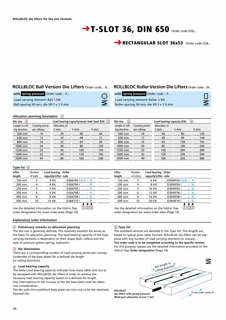
Load carrying element: Ball 1 kN
Ball spacing 50 mm, die lift f = 1.5 mm
Load carrying element: Roller 2 kN
Roller spacing 50 mm, die lift f = 1.5 mm
Carrying points per rollway
10121620253240
2 slots
20243240506480
6 slots
607296120150192240
Length in roll- ing direction
500 mm 630 mm 800 mm 1000 mm 1250 mm 1600 mm 2000 mm
Carrying points per rollway
10121620253240
2 slots
40486480100128160
4 slots
8096128160200256320
6 slots
120144192240300384480
4 slots
40486480
100128160
Lifterlength
150 mm 200 mm 250 mm 300 mm 400 mm 500 mm
Load bearingcapacity/Lifter
3 kN 4 kN 5 kN 6 kN 8 kN 10 kN
Numberof balls
3456810
Ordercode
D36KF03 / 610 – ND36KF04 / . . . – ND36KF05 / . . . – ND36KF06 / . . . – ND36KF08 / . . . – ND36KF10 / . . . – N
PreisDM
121.–145.–195.–230.–260.–300.–
Lifterlength
150 mm 200 mm 250 mm 300 mm 400 mm 500 mm
Load bearingcapacity/Lifter
6 kN 8 kN 10 kN 12 kN 16 kN 20 kN
Numberof rollers
3456810
Ordercode
D36WF03 / 610 L ND36WF04 / . . . L ND36WF05 / . . . L ND36WF06 / . . . L ND36WF08 / . . . L ND36WF10 / . . . L N
PreisDM
121.–145.–195.–230.–260.–300.–
Preliminary remarks on allocation planningThe slot size is generally defined. The relatively heaviest die serves as the basis for allocation planning. The load bearing capacity of the load carrying elements is dependent on their shape (ball, rollers) and the type of pressure system (spring, hydraulic).
Die dimensionsThere are a corresponding number of load carrying points per runway (underside of die base plate) for a defined die length (in rolling direction).
Load bearing capacityThe table Load bearing capacity indicates how many table slots are to be equipped with ROLLBLOC die lifters in order to achieve the necessary load bearing capacity based on a defined die length. Any interruptions in the runway at the die base plate must be taken into consideration.The die with the small/short base plate can turn out to be the relatively heaviest die.
Type listThe standard versions are detailed in the Type list. The lengths are based on typical press table formats. ROLLBLOC die lifters can be sup-plied with any number of load carrying elements on request.The order code is to be completed according to the specific version. For this purpose, please use the detailed information provided on the fold-in flap Order designation (Page 14).
Explanatory order information
4
2
3
1
Use the detailed information on the fold-in flap order designation for exact order data (Page 14).
Use the detailed information on the fold-in flap order designation for exact order data (Page 14).
M
1
M
2
M
3
M
1
M
2
M
3
Length in roll- ing direction
500 mm 630 mm 800 mm 1000 mm 1250 mm 1600 mm 2000 mm
Load bearing capacity/mean limit load (kN) Allocation of
Load bearing capacity (kN) Allocation of
Die size Die size
Die length in
rolling direction
Cross-over zone AROLLBLOC die lifters with spring pressure Multi-part allocation of one T-slot
Allocation planning (examples)
ROLLBLOC Roller Version Die Lifters Order code ...W... with spring pressure Order code ...F...
ROLLBLOC Ball Version Die Lifters Order code ...K...
with spring pressure Order code ...F...
2 3 2 3
21
Breite: 65 mmStrichstärke: 0,3mmGröße wie Katalog
3 32 2
Lifterlength
400 mm 500 mm 600 mm 700 mm 800 mm 900 mm 1000 mm 1100 mm 1250 mm 1400 mm 1550 mm 1750 mm 2000 mm
CRECTANGULAR SLOT 36x53 Order code D36...
CT-SLOT 36, DIN 650 Order code D36...
Load carrying element: Ball 2 kN, op pressure 40 bar (4 MPa)
Ball spacing 50 mm, die lift f = 1.5 mm
Oil volume/Ball 1.2 cm³
Load carrying element: Roller 4 kN, op pressure 80 bar (8 MPa)
Roller spacing 50 mm, die lift f = 1.5 mm
Oil volume/Roller 1.2 cm³
Length in roll- ing direction
500 mm 630 mm 800 mm 1000 mm 1250 mm 1600 mm 2000 mm
Carrying points per rollway
10121620253240
2 slots
40486480
100128160
6 slots
120144192240300384480
1
Load bearing capacity (kN) Allocation of
Die size
4 slots
8096
128160200256320
Carrying points per rollway
10121620253240
2 slots
8096128160200256320
6 slots
240288384480600768960
Load bearing capacity (kN) Allocation of
Die size
4 slots
160192256320400512640
Use the detailed information on the fold-in flap order designation for exact order data (Page 14).
Use the detailed information on the fold-in flap order designation for exact order data (Page 14).
Load bearingcapacity/Lifter
16 kN 20 kN 24 kN 28 kN 32 kN 36 kN 40 kN 44 kN 50 kN 56 kN 62 kN 70 kN 80 kN
Numberof balls
8101214161820222528313540
Ordercode
D36KH08 / 610 – N RD36KH10 / . . . – N RD36KH12 / . . . – N RD36KH14 / . . . – N RD36KH16 / . . . – N RD36KH18 / . . . – N RD36KH20 / . . . – N RD36KH22 / . . . – N RD36KH25 / . . . – N RD36KH28 / . . . – N RD36KH31 / . . . – N RD36KH35 / . . . – N RD36KH40 / . . . – N R
PreisDM
145.–195.–230.–260.–300.–350.–400.–121.–145.–
Type list 4
Lifterlength
400 mm 500 mm 600 mm 700 mm 800 mm 900 mm 1000 mm 1100 mm 1250 mm 1400 mm 1550 mm 1750 mm 2000 mm
Load bearingcapacity/Lifter
32 kN 40 kN 48 kN 56 kN 64 kN 72 kN 80 kN 88 kN 100 kN 112 kN 124 kN 140 kN 160 kN
Numberof rollers
8101214161820222528313540
Ordercode
D36WH08 / 610 L N R D36WH10 / . . . L N RD36WH12 / . . . L N RD36WH14 / . . . L N RD36WH16 / . . . L N R D36WH18 / . . . L N R D36WH20 / . . . L N RD36WH22 / . . . L N RD36WH25 / . . . L N RD36WH28 / . . . L N RD36WH31 / . . . L N RD36WH35 / . . . L N RD36WH40 / . . . L N R
PreisDM
145.–195.–230.–260.–300.–350.–400.–121.–145.–
M
2
M
1
M
3
M
4
M
2
M
1
M
3
M
4
Length in roll- ing direction
500 mm 630 mm 800 mm 1000 mm 1250 mm 1600 mm 2000 mm
Explanatory order information
ROLLBLOCdie lifterswith hydraulic pressure in standard and special versions
Allocation planning (examples)
Special ROLLBLOC T-version die lifters should be used for the purpose of crossing over table recesses (bridge function). If necessary, for production purposes, these die lifters can be removed from the table slot. They are disconnected from the hydraulic system by means of a quick-release coupling (Page 25).
See opposite page for 1 2 3 Only ROLLBLOC roller version die lifters are suitable for overhead installation.
ROLLBLOC Roller Version Die Lifters Order code ...W... with hydraulic pressure Order code ...H...
ROLLBLOC Ball Version Die Lifters Order code ...K...
with hydraulic pressure Order code ...H...
22
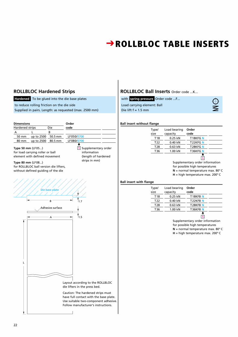
CROLLBLOC TABLE INSERTS (MATCHING DIE LIFTERS CONFORMING TO DIN 650)
Load carrying element: Ball
Die lift f = 1.5 mm
Ball insert without flange
Ball insert with flange
Ordercode
T18KFG NT22KFG NT28KFG NT36KFG N
Preis/DM
121.–121.–121.–121.–
Type/size
T18T22T28T36
Load bearingcapacity
0.25 kN0.40 kN0.63 kN1.00 kN
Preis/DM
121.–121.–121.–
Die
B50.5 mm80.5 mm
Hardened stripsDimensions Order
code
LF050/0700 LF080/0700
A50 mm80 mm
Lup to 2500up to 2500
Ordercode
T18KFB NT22KFB NT28KFB NT36KFB N
Preis/DM
121.–121.–121.–121.–
Type/size
T18T22T28T36
Load bearingcapacity
0.25 kN0.40 kN0.63 kN1.00 kN
ROLLBLOC Ball Inserts Order code ...K...
with spring pressure Order code ...F...
ROLLBLOC Hardened Strips Hardened To be glued into the die base plates
Supplementary order information for possible high temperaturesN = normal temperature max. 80° CH = high temperature max. 200° C
M
1
Supplementary order information (length of hardened strips in mm)
M
1
Supplementary order information for possible high temperaturesN = normal temperature max. 80° CH = high temperature max. 200° C
M
1
Bestell-Code LF 050 L 1050
Bei erschwerten Bedingungen wirdzus tzlich die Verschraubungmit Senkschrauben M5x10DIN7991 empfohlen
B
1.5
1.7
A
L
Die base plate
Adhesive surface
to reduce rolling friction on the die side
Supplied in pairs. Length: as requested (max. 2500 mm)
Type 50 mm (LF05...) for load carrying roller or ball element with defined movement
Type 80 mm (LF08...) for ROLLBLOC ball version die lifters, without defined guiding of the die
Layout according to the ROLLBLOC die lifters in the press bed.
Caution: The hardened strips must have full contact with the base plate. Use suitable two-component adhesive. Follow manufacturer‘s instructions.

23
Breite: 65 mmStrichstärke: 0,3mmGröße wie Katalog
CROLLBLOC TABLE INSERTS (MATCHING DIE LIFTERS CONFORMING TO DIN 650)
Load carrying element: Roller
Die lift f = 1.5 mm
Roller insert without flange
Ordercode
T18WFG NT22WFG NT28WFG NT36WFG N
Preis/DM
121.–121.–121.–121.–
Type/size
T18T22T28T36
Load bearingcapacity
0.50 kN0.80 kN1.25 kN2.00 kN
Ordercode
T18WFB NT22WFB NT28WFB NT36WFB N
Preis/DM
121.–121.–121.–121.–
Type/size
T18T22T28T36
Load bearingcapacity
0.50 kN0.80 kN1.25 kN2.00 kN
Roller insert with flange
ROLLBLOC Roller Inserts Order code ...W...
with spring pressure Order code ...F...
T
Ø E
Ø D
L
Ø E
E
Ø10
1.5
1.5
for removal
T
Ø E
Ø D
L
Ø E
E
Ø10
1.5
1.5
for removal
without flange with flangeInsertsType/size T18 T22 T28
T36
T+0,1
3,5456
T+0,1
3,5456
Ø E H9
20243040
Ø E H9
20243040
L+0,2
30384453
Dimensions for table holes
Ø D+0,2
25303550
Holes for ROLLBLOC table inserts
With this design existing holes for drawing pins can be used.
Supplementary order information for possible high temperaturesN = normal temperature max. 80° CH = high temperature max. 200° C
M
1
Supplementary order information for possible high temperaturesN = normal temperature max. 80° CH = high temperature max. 200° C
M
1
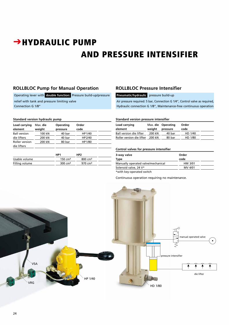
CHYDRAULIC PUMP AND PRESSURE INTENSIFIER
Standard version hydraulic pump
relief with tank and pressure limiting valve
Connection G 1/8“
Operatingpressure
40 bar40 bar80 bar
Ordercode
HP1/40HP2/40HP1/80
Preis/DM
121.–121.–121.–
.–
ROLLBLOC Pump for Manual Operation Operating lever with double function: Pressure build-up/pressure
VSA
VRGHP 1/40
HD 1/80
Standard version pressure intensifier
Preis/DM
121.–121.–12–
ROLLBLOC Pressure Intensifier Pneumatic/hydraulic pressure build-up
Air pressure required: 5 bar, Connection G 1/4“, Control valve as required,
Hydraulic connection G 1/8“, Maintenance-free continuous operation
HP2
800 cm³970 cm³
HP1
150 cm³300 cm³
Usable volumeFilling volume
24
pressure intensifier
die lifter
manual operated valve
Ordercode
HM 3/01MV 4/01
Control valves for pressure intensifier
Preis/DM
121.–121.–12–
3-way valveType
Manually operated valve/mechanicalSolenoid valve, 24 V**with key-operated switch
Continuous operation requiring no maintenance.
Max. die weight
100 kN200 kN200 kN
Load carryingelement
Ball versiondie liftersRoller versiondie lifters
Operatingpressure
40 bar80 bar
Ordercode
HD 1/40HD 1/80
Max. die weight
200 kN200 kN
Load carryingelement
Ball version die lifterRoller version die lifter
Breite: 65 mmStrichstärke: 0,3mmGröße wie Katalog
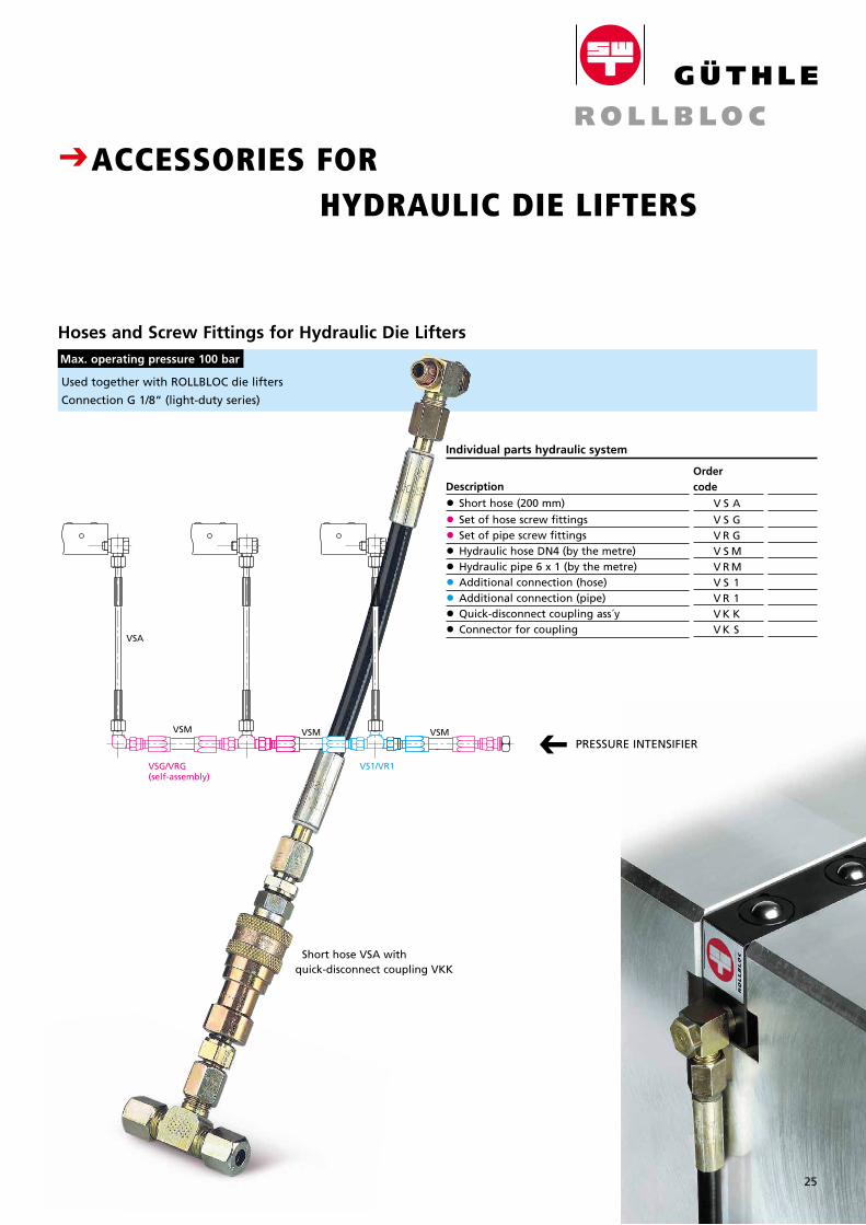
CACCESSORIES FOR HYDRAULIC DIE LIFTERS
C
Individual parts hydraulic system
Used together with ROLLBLOC die lifters
Connection G 1/8“ (light-duty series)
Description
• Short hose (200 mm)
• Set of hose screw fittings
• Set of pipe screw fittings
• Hydraulic hose DN4 (by the metre)
• Hydraulic pipe 6 x 1 (by the metre)
• Additional connection (hose)
• Additional connection (pipe)
• Quick-disconnect coupling ass´y
• Connector for coupling
Ordercode
V S A
V S G V R G V S M V R M V S 1 V R 1 V K K V K S
Hoses and Screw Fittings for Hydraulic Die Lifters Max. operating pressure 100 bar
VSA
VSG/VRG(self-assembly)
VS1/VR1
VSM VSM VSMPRESSURE INTENSIFIER
Short hose VSA with quick-disconnect coupling VKK
25
26
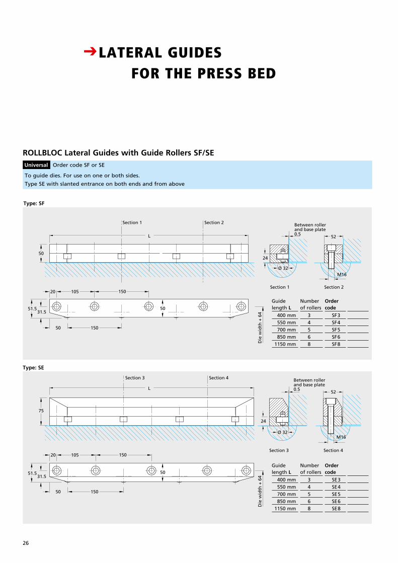
ROLLBLOC Lateral Guides with Guide Rollers SF/SE Universal Order code SF or SE
31.551.5
50 150
105 15020
L
31.5
50 150
75
51.5
50
50
L
105 15020
50
Die
wid
th +
64
Die
wid
th +
64
M16Ø 32
24
24
Ø 32
Between rollerand base plate0.5
M16
Section 1 Section 2
Section 1 Section 2
Section 3 Section 4
Section 3 Section 4
Between rollerand base plate0.5
52
52
31.551.5
50 150
105 15020
L
31.5
50 150
75
51.5
50
50
L
105 15020
50
Die
wid
th +
64
Die
wid
th +
64
M16Ø 32
24
24
Ø 32
Between rollerand base plate0.5
M16
Section 1 Section 2
Section 1 Section 2
Section 3 Section 4
Section 3 Section 4
Between rollerand base plate0.5
52
52
Type: SE
Type: SF
Guidelength L
400 mm 550 mm 700 mm 850 mm 1150 mm
Numberof rollers
3 4 5 6 8
Ordercode
SF3 SF4 SF5 SF6 SF8
PreisDM
440.–145.–195.–
.–
Guidelength L
400 mm 550 mm 700 mm 850 mm 1150 mm
Numberof rollers
3 4 5 6 8
Ordercode
SE3 SE4 SE5 SE6 SE8
PreisDM
440.–145.–195.–
.–
CLATERAL GUIDES FOR THE PRESS BED
To guide dies. For use on one or both sides.
Type SE with slanted entrance on both ends and from above
Breite: 65 mmStrichstärke: 0,3mmGröße wie Katalog
27
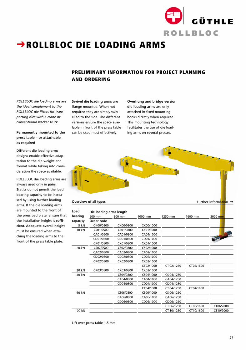
Overhung and bridge version
die loading arms are only
attached in fixed mounting
hooks directly when required.
This mounting technology
facilitates the use of die load-
ing arms on several presses.
CROLLBLOC DIE LOADING ARMS
PRELIMINARY INFORMATION FOR PROJECT PLANNING AND ORDERING
Overview of all types Further information C
CT06/2000 CT10/2000
CT02/1600
CT04/1600 CT06/1600 CT10/1600
CT 02/1250
CS 04/1250 CA 04/1250 CD 04/1250 CT 04/1250 CS 06/1250 CA 06/1250 CD 06/1250 CT 06/1250 CT 10/1250
CK00/1000CS01/1000CA01/1000CD01/1000CK01/1000CS02/1000CA02/1000CD02/1000CK02/1000CT02/1000CK03/1000CS04/1000CA04/1000CD04/1000CT04/1000CS06/1000CA06/1000CD06/1000
CK00/0800CS01/0800CA01/0800CD01/0800CK01/0800CS02/0800CA02/0800CD02/0800CK02/0800
CK03/0800CS04/0800CA04/0800CD04/0800
CS06/0800CA06/0800CD06/0800
CK00/0500CS01/0500CA01/0500CD01/0500CK01/0500CS02/0500CA02/0500CD02/0500CK02/0500
CK03/0500
Load bearing capacity 5 kN 10 kN
20 kN
30 kN 40 kN 60 kN
100 kN
Order code
Die loading arms length500 mm 800 mm 1000 mm 1250 mm 1600 mm 2000 mm
ROLLBLOC die loading arms are
the ideal complement to the
ROLLBLOC die lifters for trans-
porting dies with a crane or
conventional stacker truck.
Permanently mounted to the
press table – or attachable
as required
Different die loading arms
designs en able effective adap-
tation to the die weight and
format while taking into consi-
deration the space available.
ROLLBLOC die loading arms are
al ways used only in pairs.
Statics do not permit the load
bearing capacity to be increa-
sed by using further loading
arms. If the die loading arms
are mounted to the front of
the press bed plate, ensure that
the installation height is suffi-
cient. Adequate overall height
must be ensured when atta-
ching the loading arms to the
front of the press table plate.
Swivel die loading arms are
flange-mounted. When not
required they are simply swiv-
elled to the side. The different
versions ensure the space avai-
lable in front of the press table
can be used most effectively.
Lift over press table 1.5 mm
Breite: 65 mmStrichstärke: 0,3mmGröße wie Katalog
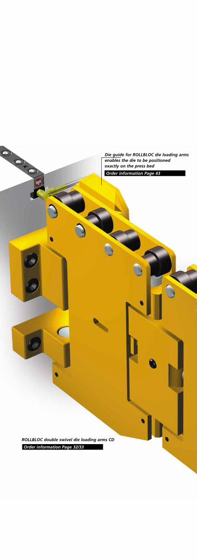
Die guide for ROLLBLOC die loading arms enables the die to be positioned exactly on the press bed
Order information Page 43
ROLLBLOC double swivel die loading arms CD
Order information Page 32/33
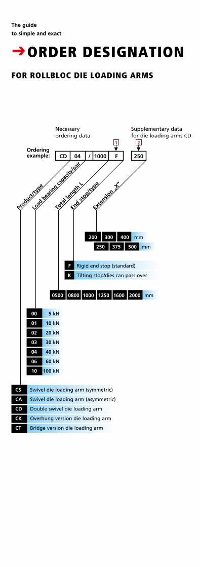
The guide
to simple and exact
CORDER DESIGNATIONFOR ROLLBLOC DIE LOADING ARMS
M
2
M
1
Product
/type
Load
bea
ring ca
pacity
/pair
CD 04 1000/ F 250
End st
op/type
Exte
nsion „X
“
CS Swivel die loading arm (symmetric)
CA Swivel die loading arm (asymmetric)
CD Double swivel die loading arm
CK Overhung version die loading arm
CT Bridge version die loading arm
Tota
l len
gth L
0500 0800 1000 1250 1600 2000 mm
300 400
250 375 500
mm
mm
00 5 kN
01 10 kN
02 20 kN
03 30 kN
04 40 kN
06 60 kN
10 100 kN
F Rigid end stop (standard)
K Tilting stop/dies can pass over
Necessary ordering data
Supplementary data for die loading arms CD
Ordering example:
200
28
PreisDM
Load bear- ing capacity
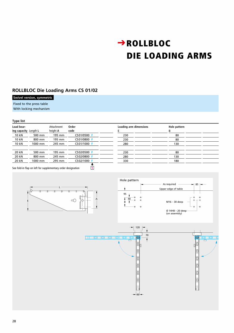
10 kN 10 kN 10 kN
20 kN 20 kN 20 kN
Length L
500 mm 800 mm 1000 mm
500 mm 800 mm 1000 mm
Attachment height A
195 mm 195 mm 245 mm
195 mm 245 mm 295 mm
Ordercode
CS01/0500 F CS01/0800 F CS01/1000 F
CS02/0500 F CS02/0800 F CS02/1000 F
Type list
Fixed to the press table
With locking mechanism
M
1
ROLLBLOC Die Loading Arms CS 01/02 Swivel version, symmetric
Loading arm dimensions Hole patternB
80 80 130
80 130 180
E
230230280
230280330
70
49
120
L
EA
Upper edge of table
As required 85
M16 – 30 deep
Ø 14H8 – 20 deep(on assembly)
B
95
40
Bohrbild
See fold-in flap on left for supplementary order designation
CROLLBLOC DIE LOADING ARMS
70
49
120
L
EA
Upper edge of table
As required 85
M16 – 30 deep
Ø 14H8 – 20 deep(on assembly)
B
95
40
Hole pattern
70
49
120
L
EA
Upper edge of table
As required 85
M16 – 30 deep
Ø 14H8 – 20 deep(on assembly)
B
95
40
29
Breite: 65 mmStrichstärke: 0,3mmGröße wie Katalog
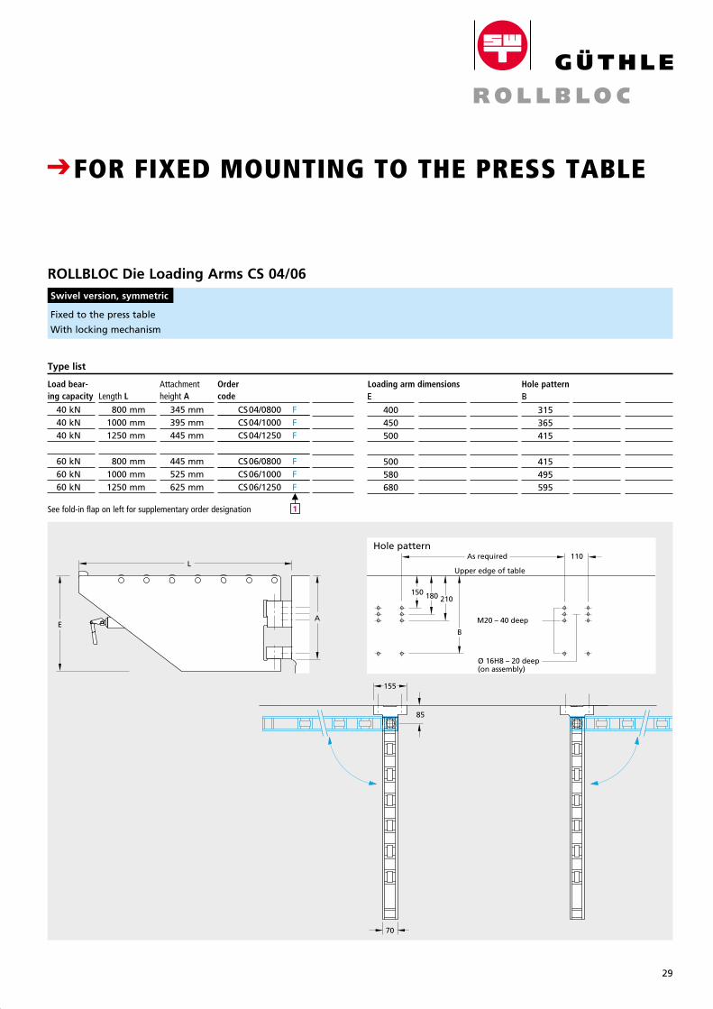
Fixed to the press table
With locking mechanism
See fold-in flap on left for supplementary order designation
ROLLBLOC Die Loading Arms CS 04/06 Swivel version, symmetric
PreisDM
Load bear- ing capacity
40 kN 40 kN 40 kN
60 kN 60 kN 60 kN
Length L
800 mm 1000 mm 1250 mm
800 mm 1000 mm 1250 mm
Attachment height A
345 mm 395 mm 445 mm
445 mm 525 mm 625 mm
Ordercode
CS04/0800 F CS04/1000 F CS04/1250 F
CS06/0800 F CS06/1000 F CS06/1250 F
Type list
M
1
Hole patternB
315365415
415495595
Loading arm dimensionsE
400450500
500580680
CFOR FIXED MOUNTING TO THE PRESS TABLE
Upper edge of table
E
180150210
B
110
M20 – 40 deep
Ø 16H8 – 20 deep(on assembly)
LAs required
70
155
85
A
Upper edge of table
E
180150210
B
110
M20 – 40 deep
Ø 16H8 – 20 deep(on assembly)
LAs required
70
155
85
A
Upper edge of table
E
180150210
B
110
M20 – 40 deep
Ø 16H8 – 20 deep(on assembly)
LAs required
70
155
85
A
Hole pattern
30
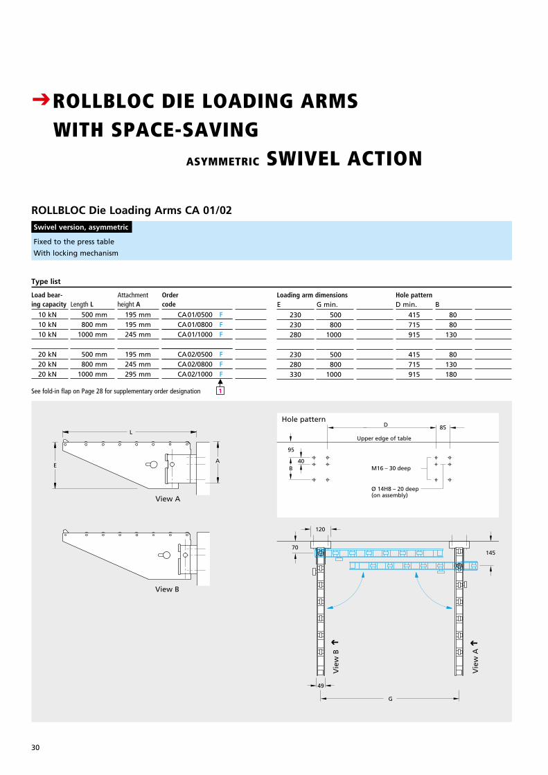
Fixed to the press table
With locking mechanism
ROLLBLOC Die Loading Arms CA 01/02 Swivel version, asymmetric
Vie
w A
C
PreisDM
Load bear- ing capacity
10 kN 10 kN 10 kN
20 kN 20 kN 20 kN
Length L
500 mm 800 mm 1000 mm
500 mm 800 mm 1000 mm
Attachment height A
195 mm 195 mm 245 mm
195 mm 245 mm 295 mm
Ordercode
CA01/0500 F CA01/0800 F CA01/1000 F
CA02/0500 F CA02/0800 F CA02/1000 F
Type list
M
1
Hole patternB
80 80 130
80 130 180
D min.
415715915
415715915
Loading arm dimensionsE
230230280
230280330
G min.
500 800 1000
500 800 1000
CROLLBLOC DIE LOADING ARMS WITH SPACE-SAVING ASYMMETRIC SWIVEL ACTION CFOR FIXED MOUNTING TO THE PRESS TABLE
Hole pattern
Vie
w B
C
See fold-in flap on Page 28 for supplementary order designation
L
E
70
49
120
G
145
A
85
Upper edge of table
M16 – 30 deep
Ø 14H8 – 20 deep(on assembly)
D
40B
95
View A
View B
31
Breite: 65 mmStrichstärke: 0,3mmGröße wie Katalog
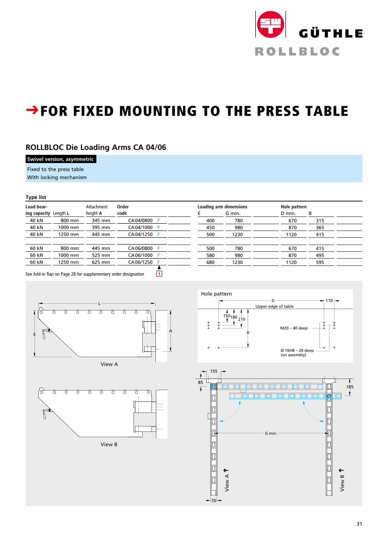
Fixed to the press table
With locking mechanism
ROLLBLOC Die Loading Arms CA 04/06 Swivel version, asymmetric
D 110
M20 – 40 deep
Ø 16H8 – 20 deep(on assembly)
180150210
B
155
85
G min.
185
L
EA
70
Upper edge of tableD 110
M20 – 40 deep
Ø 16H8 – 20 deep(on assembly)
180150210
B
155
85
G min.
185
L
EA
70
Upper edge of table
View A
View B
PreisDM
Load bear- ing capacity
40 kN 40 kN 40 kN
60 kN 60 kN 60 kN
Length L
800 mm 1000 mm 1250 mm
800 mm 1000 mm 1250 mm
Attachment height A
345 mm 395 mm 445 mm
445 mm 525 mm 625 mm
Ordercode
CA04/0800 F CA04/1000 F CA04/1250 F
CA06/0800 F CA06/1000 F CA06/1250 F
Type list
M
1
Hole patternB
315 365 415
415 495 595
D min.
670 870 1120
670 870 1120
Loading arm dimensionsE
400450500
500580680
G min.
780 980 1230
780 980 1230
CROLLBLOC DIE LOADING ARMS WITH SPACE-SAVING ASYMMETRIC SWIVEL ACTION CFOR FIXED MOUNTING TO THE PRESS TABLE
Hole patternD 110
M20 – 40 deep
Ø 16H8 – 20 deep(on assembly)
180150210
B
155
85
G min.
185
L
EA
70
Upper edge of table
D 110
M20 – 40 deep
Ø 16H8 – 20 deep(on assembly)
180150210
B
155
85
G min.
185
L
EA
70
Upper edge of table
Vie
w B
C
Vie
w A
C
See fold-in flap on Page 28 for supplementary order designation
32
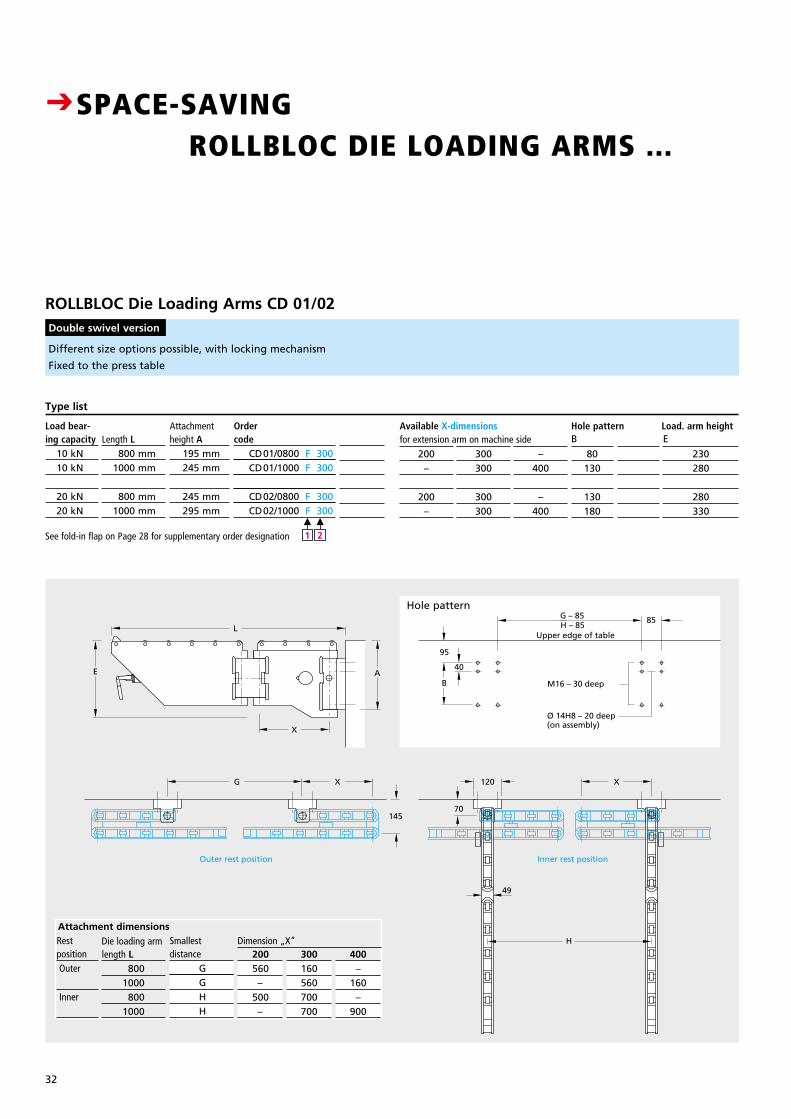
Different size options possible, with locking mechanism
Fixed to the press table
ROLLBLOC Die Loading Arms CD 01/02 Double swivel version
PreisDM
Load bear- ing capacity 10 kN 10 kN
20 kN 20 kN
Length L 800 mm 1000 mm
800 mm 1000 mm
Attachment height A 195 mm 245 mm
245 mm 295 mm
Ordercode CD01/0800 F 300 CD01/1000 F 300
CD02/0800 F 300 CD02/1000 F 300
Type list
M
1
M
2
Hole pattern Load. arm heightB
80130
130180
E
230280
280330
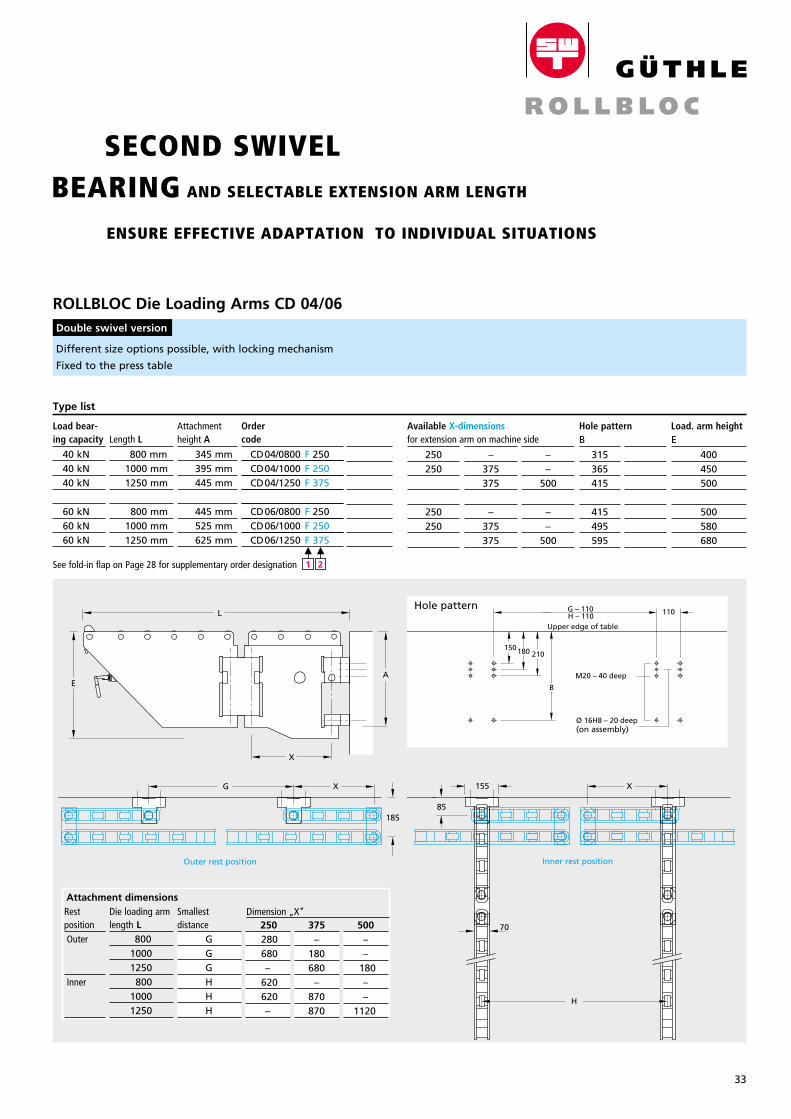
CSPACE-SAVING
ROLLBLOC DIE LOADING ARMS ... SECOND SWIVEL BEARING AND SELECTABLE EXTENSION ARM LENGTH
ENSURE EFFECTIVE ADAPTATION TO INDIVIDUAL SITUATIONS
Hole pattern
Available X-dimensions E
200–
200–
F
300300
300300
H
–400
–400
for extension arm on machine side
See fold-in flap on Page 28 for supplementary order designation
Inner rest position
70
49
H
Outer rest position
G 120
L
E A
X
X X
Upper edge of table
G – 85 85
M16 – 30 deep
Ø 14H8 – 20 deep(on assembly)
H – 85
B
95
40
145
200 560
– 500
–
Smallestdistance G G H H
300160560700700
400–
160–
900
Dimension „X“Die loading armAttachment dimensions
length L 800 1000 800 1000
Restposition Outer
Inner
33
Breite: 65 mmStrichstärke: 0,3mmGröße wie Katalog
CSPACE-SAVING
ROLLBLOC DIE LOADING ARMS ... SECOND SWIVEL BEARING AND SELECTABLE EXTENSION ARM LENGTH
ENSURE EFFECTIVE ADAPTATION TO INDIVIDUAL SITUATIONS
Different size options possible, with locking mechanism
Fixed to the press table
ROLLBLOC Die Loading Arms CD 04/06 Double swivel version
PreisDM
Load bear- ing capacity
40 kN 40 kN 40 kN
60 kN 60 kN 60 kN
Length L
800 mm 1000 mm 1250 mm
800 mm 1000 mm 1250 mm
Attachment height A
345 mm 395 mm 445 mm
445 mm 525 mm 625 mm
Type list
M
1
M
2
Hole pattern Load. arm heightB
315365415
415495595
E
400450500
500580680
D
X
H
G – 110H – 110
E
Upper edge of table
110
M20 – 40 deep
Ø 16H8 – 20 deep(on assembly)
180150210
B
L
X
A
Inner rest position
155
85
70
Outer rest position
XG
185
Hole pattern
X
H
G – 110H – 110
E
Upper edge of table
110
M20 – 40 deep
Ø 16H8 – 20 deep(on assembly)
180150210
B
L
X
A
Inner rest position
155
85
70
Outer rest position
XG
185
X
H
G – 110H – 110
E
Upper edge of table
110
M20 – 40 deep
Ø 16H8 – 20 deep(on assembly)
180150210
B
L
X
A
Inner rest position
155
85
70
Outer rest position
XG
185
D
250250250
250250250
E
–375375
–375375
H
––
500
––
500
Available X-dimensions for extension arm on machine side
See fold-in flap on Page 28 for supplementary order designation
X
H
G – 110H – 110
E
Upper edge of table
110
M20 – 40 deep
Ø 16H8 – 20 deep(on assembly)
180150210
B
L
X
A
Inner rest position
155
85
70
Outer rest position
XG
185
Die loading armlength L 800 1000 1250 800 1000 1250
Restposition Outer
Inner
250 280 680
– 620 620
–
Smallestdistance G G G H H H
500––
180––
1120
Dimension „X“ Attachment dimensions
375–
180 680
– 870 870
Ordercode
CD04/0800 F 250 CD04/1000 F 250 CD04/1250 F 375
CD06/0800 F 250 CD06/1000 F 250 CD06/1250 F 375
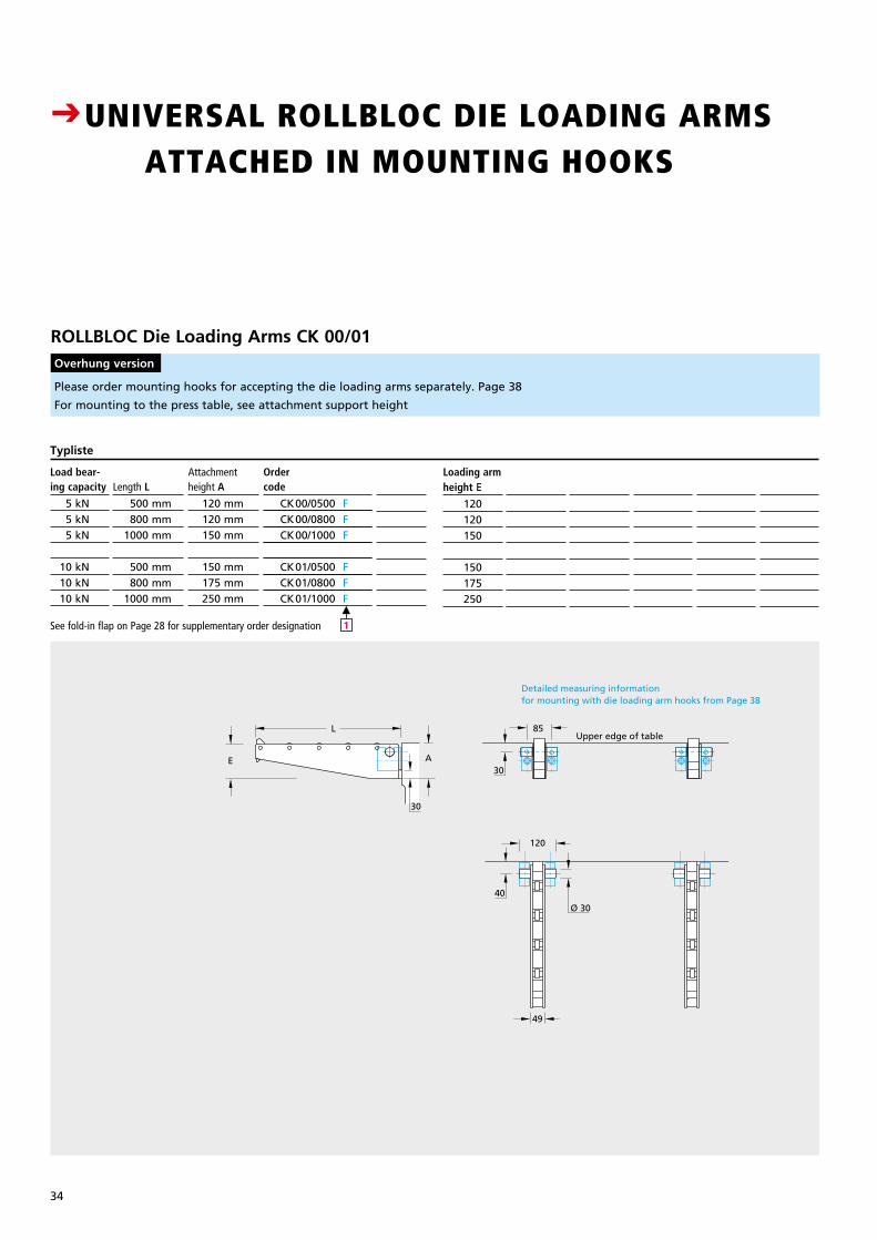
34
Please order mounting hooks for accepting the die loading arms separately. Page 38
For mounting to the press table, see attachment support height
M
1
ROLLBLOC Die Loading Arms CK 00/01 Overhung version
Upper edge of table
Detailed measuring informationfor mounting with die loading arm hooks from Page 38
L
E A
49
120
40
Ø 30
85
30
30 Upper edge of table
Detailed measuring informationfor mounting with die loading arm hooks from Page 38
L
E A
49
120
40
Ø 30
85
30
30
Upper edge of table
Detailed measuring informationfor mounting with die loading arm hooks from Page 38
L
E A
49
120
40
Ø 30
85
30
30
PreisDM
Load bear- ing capacity
5 kN 5 kN 5 kN
10 kN 10 kN 10 kN
Length L
500 mm 800 mm 1000 mm
500 mm 800 mm 1000 mm
Attachment height A
120 mm 120 mm 150 mm
150 mm 175 mm 250 mm
Ordercode
CK00/0500 F CK00/0800 F CK00/1000 F
CK01/0500 F CK01/0800 F CK01/1000 F
Typliste
Loading armheight E
120120150
150175250
CUNIVERSAL ROLLBLOC DIE LOADING ARMS
ATTACHED IN MOUNTING HOOKS
See fold-in flap on Page 28 for supplementary order designation
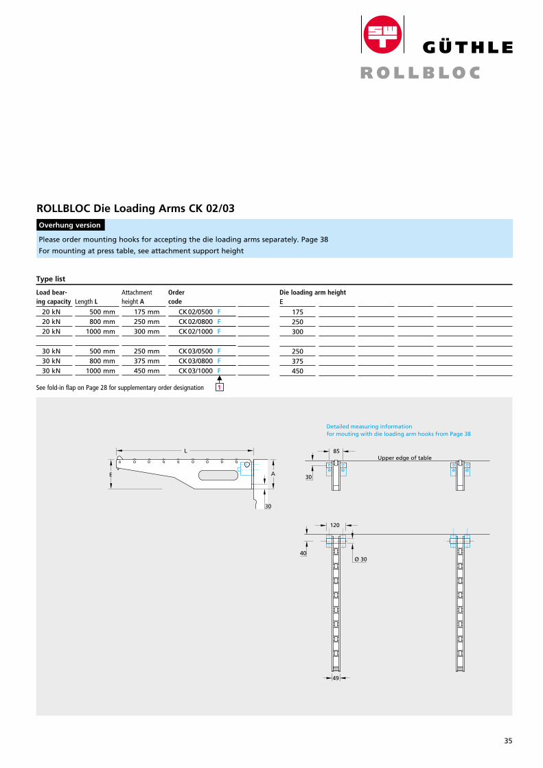
35
Breite: 65 mmStrichstärke: 0,3mmGröße wie Katalog
Detailed measuring informationfor mouting with die loading arm hooks from Page 38
Upper edge of table
L
E A
85
120
49
30
Ø 30
30
40
Detailed measuring informationfor mouting with die loading arm hooks from Page 38
Upper edge of table
L
E A
85
120
49
30
Ø 30
30
40
Detailed measuring informationfor mouting with die loading arm hooks from Page 38
Upper edge of table
L
E A
85
120
49
30
Ø 30
30
40
Please order mounting hooks for accepting the die loading arms separately. Page 38
For mounting at press table, see attachment support height
ROLLBLOC Die Loading Arms CK 02/03 Overhung version
PreisDM
Load bear- ing capacity
20 kN 20 kN 20 kN
30 kN 30 kN 30 kN
Length L
500 mm 800 mm 1000 mm
500 mm 800 mm 1000 mm
Attachment height A
175 mm 250 mm 300 mm
250 mm 375 mm 450 mm
Ordercode
CK02/0500 F CK02/0800 F CK02/1000 F
CK03/0500 F CK03/0800 F CK03/1000 F
Type list
Die loading arm heightE
175250300
250375450
M
1See fold-in flap on Page 28 for supplementary order designation
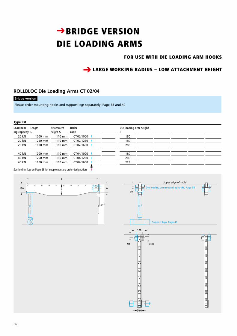
36
Please order mounting hooks and support legs separately. Page 38 and 40
M
1
ROLLBLOC Die Loading Arms CT 02/04 Bridge version
Upper edge of table
Support legs, Page 40
Die loading arm mounting hooks, Page 38
30A130 E
L
120
40
49
120
40 Ø 30
49
Upper edge of table
Support legs, Page 40
Die loading arm mounting hooks, Page 38
30A130 E
L
120
40
49
120
40 Ø 30
49
Upper edge of table
Support legs, Page 40
Die loading arm mounting hooks, Page 38
30A130 E
L
120
40
49
120
40 Ø 30
49
PreisDM
Load bear- ing capacity
20 kN 20 kN 20 kN
40 kN 40 kN 40 kN
LengthL
1000 mm 1250 mm 1600 mm
1000 mm 1250 mm 1600 mm
Attachment height A
110 mm 110 mm 110 mm
110 mm 110 mm 110 mm
Ordercode
CT02/1000 F CT02/1250 F CT02/1600 F
CT04/1000 F CT04/1250 F CT04/1600 F
Type list
Die loading arm heightE
150180205
180205225
CBRIDGE VERSION DIE LOADING ARMS
See fold-in flap on Page 28 for supplementary order designation
FOR USE WITH DIE LOADING ARM HOOKS
LARGE WORKING RADIUS – LOW ATTACHMENT HEIGHTC
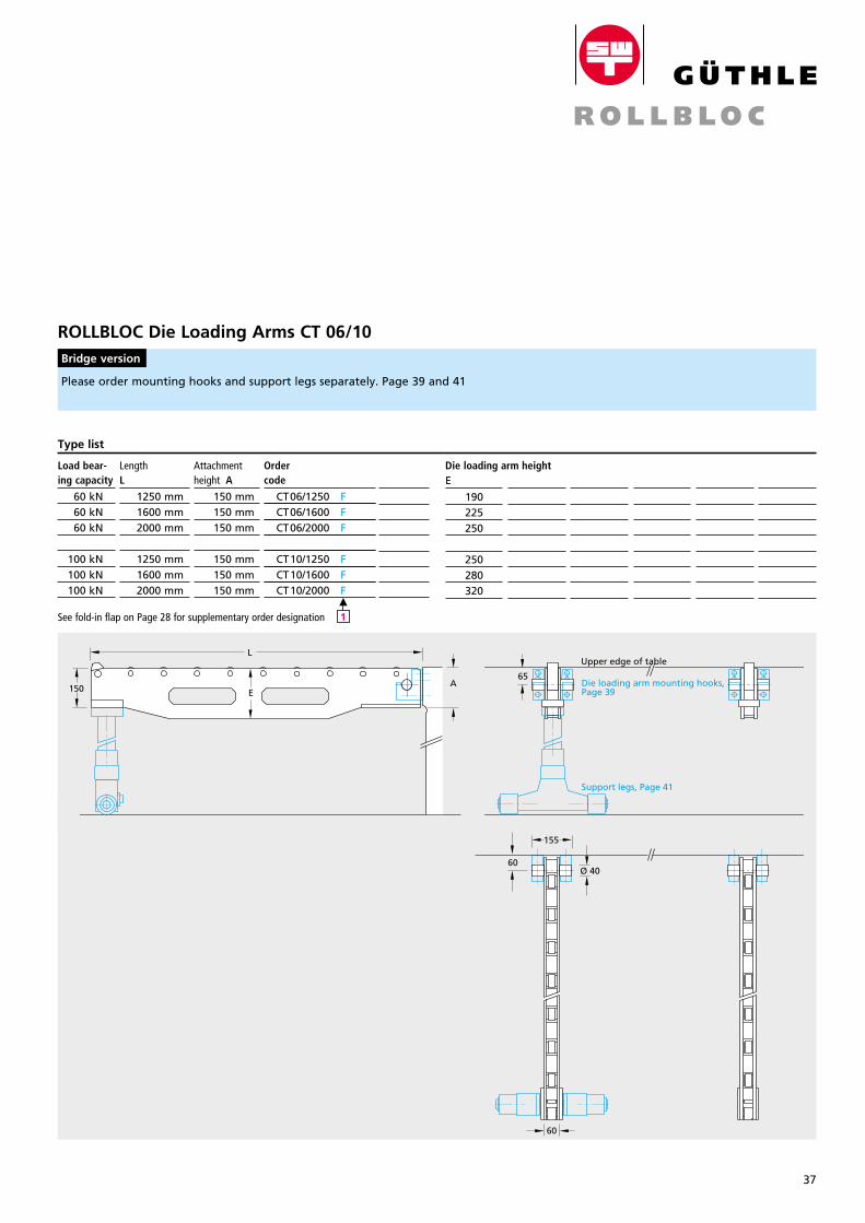
37
Breite: 65 mmStrichstärke: 0,3mmGröße wie Katalog
Please order mounting hooks and support legs separately. Page 39 and 41
ROLLBLOC Die Loading Arms CT 06/10 Bridge version
Die loading arm mounting hooks,Page 39
Support legs, Page 41
Upper edge of table
65
L
150
60
155
60Ø 40
AE
Die loading arm mounting hooks,Page 39
Support legs, Page 41
Upper edge of table
65
L
150
60
155
60Ø 40
AE
Die loading arm mounting hooks,Page 39
Support legs, Page 41
Upper edge of table
65
L
150
60
155
60Ø 40
AE
PreisDM
Load bear- ing capacity
60 kN 60 kN 60 kN
100 kN 100 kN 100 kN
LengthL
1250 mm 1600 mm 2000 mm
1250 mm 1600 mm 2000 mm
Attachmentheight A
150 mm 150 mm 150 mm
150 mm 150 mm 150 mm
Ordercode
CT06/1250 F CT06/1600 F CT06/2000 F
CT10/1250 F CT10/1600 F CT10/2000 F
Type list
Die loading arm heightE
190225250
250280320
M
1See fold-in flap on Page 28 for supplementary order designation
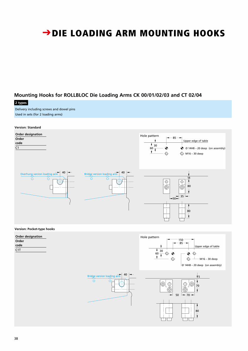
38
Mounting Hooks for ROLLBLOC Die Loading Arms CK 00/01/02/03 and CT 02/04 2 types
Delivery including screws and dowel pins
Used in sets (for 2 loading arms)
40
Overhung version loading arm Bridge version loading arm
Kragkonsole Bridge version loading arm
Upper edge of table
M16 – 30 deep
Ø 14H8 – 20 deep (on assembly)
M16 – 30 deep
Ø 14H8 – 20 deep (on assembly)30
60
Upper edge of table
80
70
70
14
5
50
30
35
85
40
40 40
15085
60
80
50
80
40
Overhung version loading arm Bridge version loading arm
Kragkonsole Bridge version loading arm
Upper edge of table
M16 – 30 deep
Ø 14H8 – 20 deep (on assembly)
M16 – 30 deep
Ø 14H8 – 20 deep (on assembly)30
60
Upper edge of table
80
70
70
14
5
50
30
35
85
40
40 40
15085
60
80
50
80
40
Overhung version loading arm Bridge version loading arm
Kragkonsole Bridge version loading arm
Upper edge of table
M16 – 30 deep
Ø 14H8 – 20 deep (on assembly)
M16 – 30 deep
Ø 14H8 – 20 deep (on assembly)30
60
Upper edge of table
80
70
70
14
5
50
30
35
85
40
40 40
15085
60
80
50
80
40
Overhung version loading arm Bridge version loading arm
Kragkonsole Bridge version loading arm
Upper edge of table
M16 – 30 deep
Ø 14H8 – 20 deep (on assembly)
M16 – 30 deep
Ø 14H8 – 20 deep (on assembly)30
60
Upper edge of table
80
70
70
14
5
50
30
35
85
40
40 40
15085
60
80
50
80
Hole pattern
Hole pattern
Version: Standard
Version: Pocket-type hooks
CDIE LOADING ARM MOUNTING HOOKS
CCOMPACT DESIGN FOR FAST MOUNTING OF OVERHUNG AND BRIDGE VERSION
DIE LOADING ARMS TO THE PRESS TABLE
Order designation
Order code
C1
Order designation
Ordercode
C1T
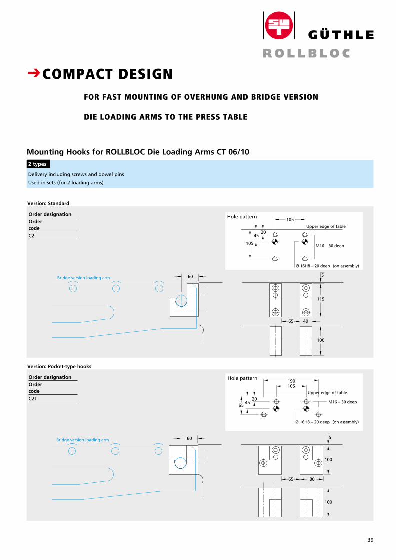
39
Breite: 65 mmStrichstärke: 0,3mmGröße wie Katalog
Mounting Hooks for ROLLBLOC Die Loading Arms CT 06/10 2 types
Upper edge of table
M16 – 30 deep
Ø 16H8 – 20 deep (on assembly)
45
105
20
40
115
80
100
65
65
105
Bridge version loading arm
Bridge version loading arm
100
100
190
M16 – 30 deep
Ø 16H8 – 20 deep (on assembly)
Upper edge of table
4520
65
105
60
60
5
5
Upper edge of table
M16 – 30 deep
Ø 16H8 – 20 deep (on assembly)
45
105
20
40
115
80
100
65
65
105
Bridge version loading arm
Bridge version loading arm
100
100
190
M16 – 30 deep
Ø 16H8 – 20 deep (on assembly)
Upper edge of table
4520
65
105
60
60
5
5
Upper edge of table
M16 – 30 deep
Ø 16H8 – 20 deep (on assembly)
45
105
20
40
115
80
100
65
65
105
Bridge version loading arm
Bridge version loading arm
100
100
190
M16 – 30 deep
Ø 16H8 – 20 deep (on assembly)
Upper edge of table
4520
65
105
60
60
5
5
Upper edge of table
M16 – 30 deep
Ø 16H8 – 20 deep (on assembly)
45
105
20
40
115
80
100
65
65
105
Bridge version loading arm
Bridge version loading arm
100
100
190
M16 – 30 deep
Ø 16H8 – 20 deep (on assembly)
Upper edge of table
4520
65
105
60
60
5
5
Delivery including screws and dowel pins
Used in sets (for 2 loading arms)
Hole pattern
Hole pattern
CDIE LOADING ARM MOUNTING HOOKS
CCOMPACT DESIGN FOR FAST MOUNTING OF OVERHUNG AND BRIDGE VERSION
DIE LOADING ARMS TO THE PRESS TABLE
Version: Standard
Version: Pocket-type hooks
Order designation
Ordercode
C2
Order designation
Ordercode
C2T
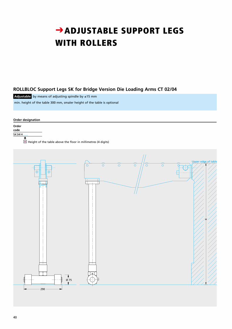
40
ROLLBLOC Support Legs SK for Bridge Version Die Loading Arms CT 02/04 Adjustable by means of adjusting spindle by ±15 mm
Ordercode
SK04 H. . . .
min. height of the table 300 mm, smaler height of the table is optional
CADJUSTABLE SUPPORT LEGS WITH ROLLERS
Upper edge of table
Upper edge of table
H
H
290
Ø 75
420
Ø 75
Upper edge of table
Upper edge of table
H
H
290
Ø 75
420
Ø 75
Order designation
M
H Height of the table above the floor in millimetres (4 digits)
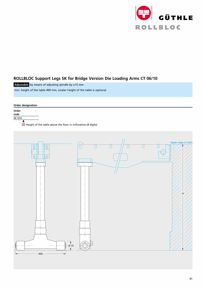
41
Breite: 65 mmStrichstärke: 0,3mmGröße wie Katalog
ROLLBLOC Support Legs SK for Bridge Version Die Loading Arms CT 06/10 Adjustable by means of adjusting spindle by ±15 mm
min. height of the table 400 mm, smaler height of the table is optional
CADJUSTABLE SUPPORT LEGS WITH ROLLERS
Upper edge of table
Upper edge of table
H
H
290
Ø 75
420
Ø 75
Upper edge of table
Upper edge of table
H
H
290
Ø 75
420
Ø 75Order code
SK10 H. . . .
Order designation
M
H Height of the table above the floor in millimetres (4 digits)
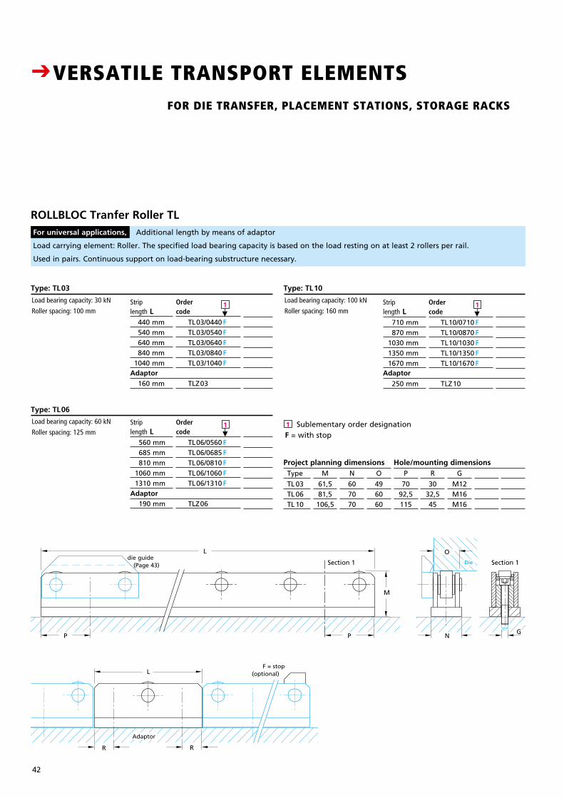
42
PreisDM
440.–145.–195.–
230.–
Strip length L 440 mm 540 mm 640 mm 840 mm 1040 mm
160 mm
Adaptor
Adaptor
Adaptor
Ordercode
TL03/0440 F TL03/0540 F TL03/0640 F TL03/0840 F TL03/1040 F
TLZ03
Load bearing capacity: 30 kN
Roller spacing: 100 mm
Sublementary order designationF = with stop
PreisDM
440.–145.–195.–
230.–
Strip length L 560 mm 685 mm 810 mm 1060 mm 1310 mm
190 mm
Ordercode
TL06/0560 F TL06/0685 F TL06/0810 F TL06/1060 F TL06/1310 F
TLZ06
Load bearing capacity: 60 kN
Roller spacing: 125 mm
PreisDM
440.–145.–195.–
230.–
Strip length L 710 mm 870 mm 1030 mm 1350 mm 1670 mm
250 mm
Ordercode
TL10/0710 F TL10/0870 F TL10/1030 F TL10/1350 F TL10/1670 F
TLZ10
Load bearing capacity: 100 kN
Roller spacing: 160 mm
Type: TL03
Type: TL06
Type: TL10
CVERSATILE TRANSPORT ELEMENTS FOR DIE TRANSFER, PLACEMENT STATIONS, STORAGE RACKS
ROLLBLOC Tranfer Roller TL For universal applications, Additional length by means of adaptor
Load carrying element: Roller. The specified load bearing capacity is based on the load resting on at least 2 rollers per rail.
Used in pairs. Continuous support on load-bearing substructure necessary.
P
Section 1 Section 1
L
M
NP
L
R R
G
O
P
Section 1 Section 1
L
M
NP
L
R R
G
O
Type
TL 03 TL 06 TL 10
Project planning dimensions Hole/mounting dimensionsN
607070
M
61,581,5106,5
O
496060
P
7092,5115
R
3032,545
H
203040
G
M12M16M16
G
M8 M12 M16
Adaptor
F = stop(optional)
M
1
M
1
M
1 1
die guide (Page 43) Die
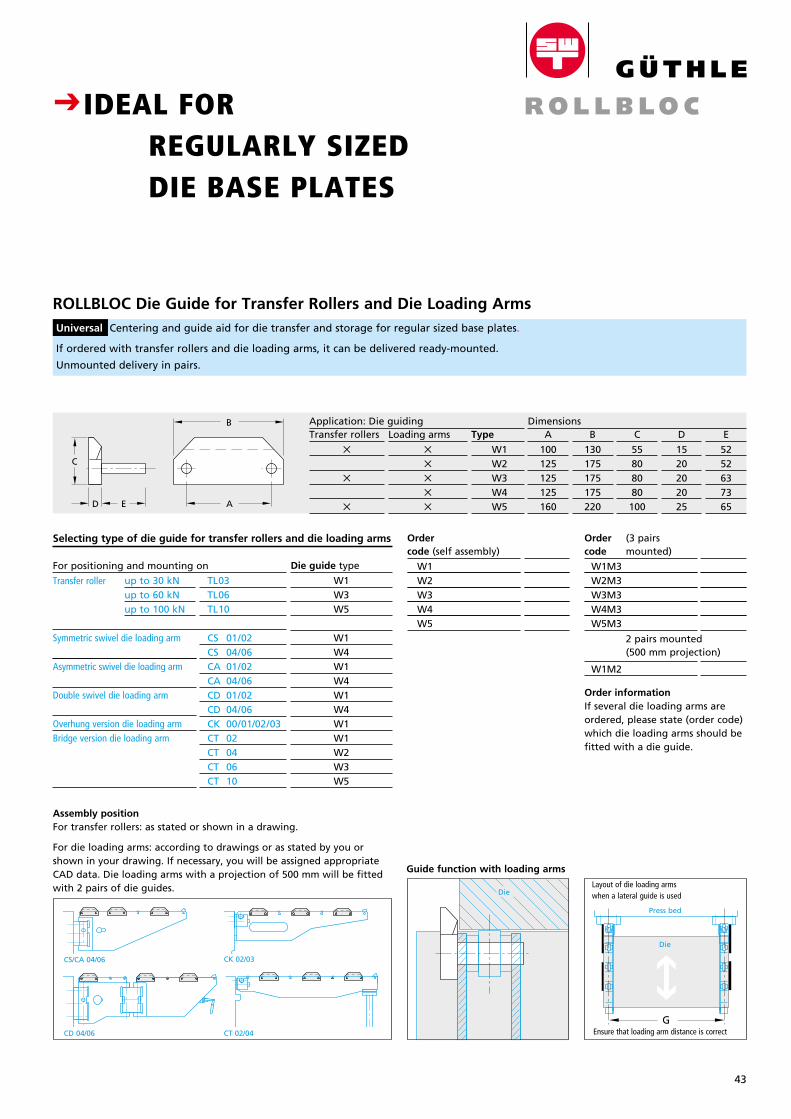
43
Breite: 65 mmStrichstärke: 0,3mmGröße wie Katalog
G
CVERSATILE TRANSPORT ELEMENTS FOR DIE TRANSFER, PLACEMENT STATIONS, STORAGE RACKS
Guide function with loading arms
CIDEAL FOR REGULARLY SIZED DIE BASE PLATES
ROLLBLOC Die Guide for Transfer Rollers and Die Loading Arms Universal Centering and guide aid for die transfer and storage for regular sized base plates.
If ordered with transfer rollers and die loading arms, it can be delivered ready-mounted.
Unmounted delivery in pairs.
Die
B
E
C
AD
Assembly positionFor transfer rollers: as stated or shown in a drawing.
For die loading arms: according to drawings or as stated by you or shown in your drawing. If necessary, you will be assigned appropriate CAD data. Die loading arms with a projection of 500 mm will be fitted with 2 pairs of die guides.
CD 04/06
CS/CA 04/06
CT 02/04
CK 02/03
A
100125125125160
B
130175175175220
C
55808080100
D
1520202025
E
5252637365
Transfer rollers
5
5
5
Loading arms
5
5
5
5
5
Type
W1 W2 W3 W4 W5
Ordercode (self assembly)
W1 W2 W3 W4 W5
W1M2
2 pairs mounted (500 mm projection)
Order (3 pairs code mounted)
W1M3 W2M3 W3M3 W4M3 W5M3
W1W4W1W4W1W4W1W1W2W3W5
Symmetric swivel die loading arm Asymmetric swivel die loading arm Double swivel die loading arm Overhung version die loading armBridge version die loading arm
Transfer roller
Selecting type of die guide for transfer rollers and die loading arms
TL03 TL06 TL10
Die guide type
W1 W3W5
For positioning and mounting on
DimensionsApplication: Die guiding
up to 30 kNup to 60 kNup to 100 kN
Layout of die loading arms when a lateral guide is used
Die
Ensure that loading arm distance is correct
Press bed
CS 01/02 CS 04/06 CA 01/02 CA 04/06 CD 01/02 CD 04/06 CK 00/01/02/03 CT 02 CT 04 CT 06 CT 10
Order informationIf several die loading arms areordered, please state (order code) which die loading arms should be fitted with a die guide.
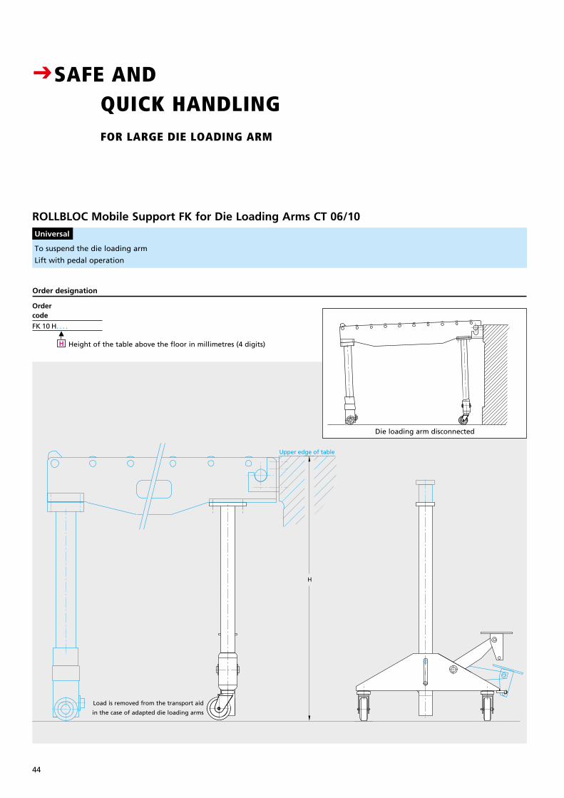
44
ROLLBLOC Mobile Support FK for Die Loading Arms CT 06/10 Universal
Ordercode
FK 10 H. . . .
Order designation
M
H Height of the table above the floor in millimetres (4 digits)
To suspend the die loading arm
Lift with pedal operation
Upper edge of table
H
Upper edge of table
H
E
CSAFE AND QUICK HANDLING FOR LARGE DIE LOADING ARM
Load is removed from the transport aid
in the case of adapted die loading arms
Die loading arm disconnected
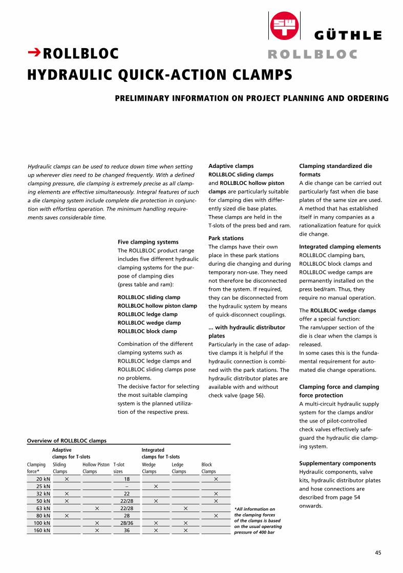
45
Breite: 65 mmStrichstärke: 0,3mmGröße wie Katalog
Five clamping systems
The ROLLBLOC product range
includes five different hydraulic
clamping systems for the pur-
pose of clamping dies
(press table and ram):
ROLLBLOC sliding clamp
ROLLBLOC hollow piston clamp
ROLLBLOC ledge clamp
ROLLBLOC wedge clamp
ROLLBLOC block clamp
Combination of the different
clamping systems such as
ROLLBLOC ledge clamps and
ROLLBLOC sliding clamps pose
no problems.
The decisive factor for selecting
the most suitable clamping
system is the planned utiliza-
tion of the respective press.
Clamping standardized die
formats
A die change can be carried out
particularly fast when die base
plates of the same size are used.
A method that has established
itself in many companies as a
rationalization feature for quick
die change.
Integrated clamping elements
ROLLBLOC clamping bars,
ROLLBLOC block clamps and
ROLLBLOC wedge camps are
permanently installed on the
press bed/ram. Thus, they
require no manual operation.
The ROLLBLOC wedge clamps
offer a special function:
The ram/upper section of the
die is clear when the clamps is
released.
In some cases this is the funda-
mental requirement for auto-
mated die change operations.
Clamping force and clamping
force protection
A multi-circuit hydraulic supply
system for the clamps and/or
the use of pilot-controlled
check valves effectively safe-
guard the hydraulic die clamp-
ing system.
Supplementary components
Hydraulic components, valve
kits, hydraulic distributor plates
and hose connections are
described from page 54
onwards.
Adaptive clamps
ROLLBLOC sliding clamps
and ROLLBLOC hollow piston
clamps are particularly suitable
for clamping dies with differ-
ently sized die base plates.
These clamps are held in the
T-slots of the press bed and ram.
Park stations
The clamps have their own
place in these park stations
during die changing and during
temporary non-use. They need
not therefore be disconnected
from the system. If required,
they can be disconnected from
the hydraulic system by means
of quick-disconnect couplings.
... with hydraulic distributor
plates
Particularly in the case of adap-
tive clamps it is helpful if the
hydraulic connection is combi-
ned with the park stations. The
hydraulic distributor plates are
available with and without
check valve (page 56).
CROLLBLOC HYDRAULIC QUICK-ACTION CLAMPS PRELIMINARY INFORMATION ON PROJECT PLANNING AND ORDERING
Hydraulic clamps can be used to reduce down time when sett ing
up wherever dies need to be changed frequently. With a defined
clamping pressure, die clamping is extremely precise as all clamp-
ing elements are effective simultaneously. Integral features of such
a die clamping system include complete die protection in conjunc-
tion with effortless operation. The minimum handling require-
ments saves considerable time.
Clampingforce*
20 kN 25 kN 32 kN 50 kN 63 kN 80 kN 100 kN 160 kN
T-slot sizes
18–
2222/2822/28
2828/36
36
SlidingClamps
5
5
5
5
LedgeClamps
5
5
5
BlockClamps
5
5
5
5
WedgeClamps
5
5
5
5
Overview of ROLLBLOC clamps
Hollow Piston Clamps
5
5
5
*All information on the clamping forces of the clamps is based on the usual operating pressure of 400 bar
Adaptive Integratedclamps for T-slots clamps for T-slots

Breite: 65 mmStrichstärke: 0,3mmGröße wie Katalog
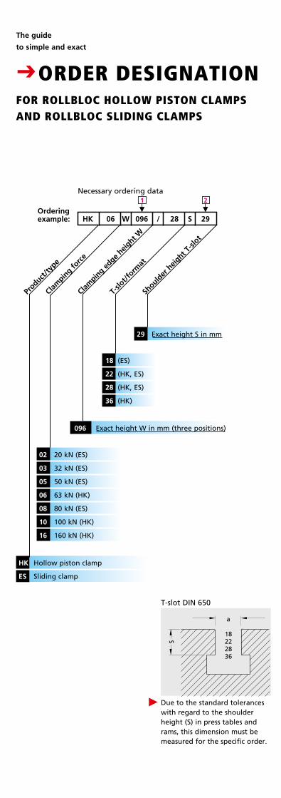
The guide
to simple and exact
CORDER DESIGNATIONFOR ROLLBLOC HOLLOW PISTON CLAMPS AND ROLLBLOC SLIDING CLAMPS
Product
/type
Clam
ping fo
rce
06 W
T-slo
t/form
at
02 20 kN (ES)
03 32 kN (ES)
05 50 kN (ES)
06 63 kN (HK)
08 80 kN (ES)
10 100 kN (HK)
16 160 kN (HK)
HK Hollow piston clamp
ES Sliding clamp
T-slot DIN 650
Should
er h
eight T
-slot
29 Exact height S in mm
Clam
ping e
dge hei
ght W
18 (ES)
22 (HK, ES)
28 (HK, ES)
36 (HK)
096 Exact height W in mm (three positions)
M
2
M
1
S
a
18222836
Due to the standard tolerances with regard to the shoulder height (S) in press tables and rams, this dimension must be measured for the specific order.
P
Necessary ordering data
Ordering example: HK 096 / 28 S 29
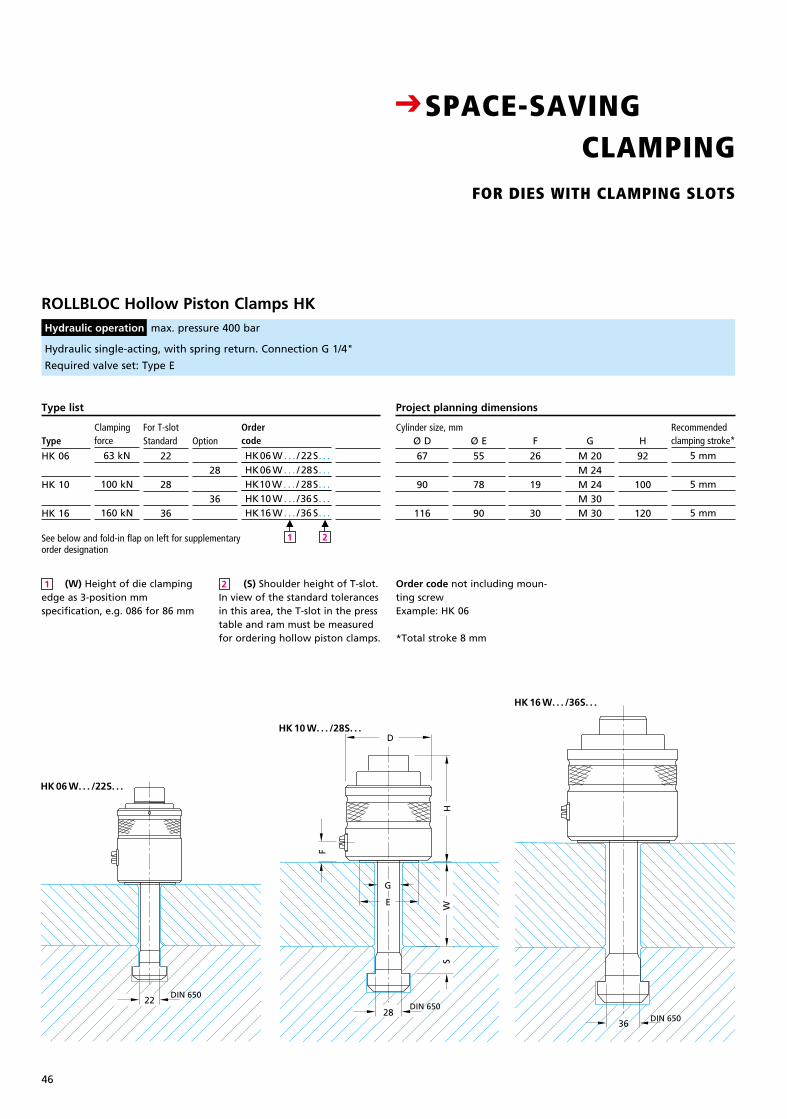
46
W
D
DIN 65036
DIN 65028
DIN 65022
H
G
E
F
S
ROLLBLOC Hollow Piston Clamps HK Hydraulic operation max. pressure 400 bar
Clampingforce
63 kN
100 kN
160 kN
Standard
22
28
36
For T-slotOption
28
36
Ø E
55
78
90
Ordercode
HK06 W . . . / 22S. . . HK06 W . . . / 28S. . . HK10 W . . . / 28S. . . HK10 W . . . /36 S. . . HK16 W . . . /36 S. . .
Type list
Type
HK 06
HK 10
HK 16
Ø D
67
90
116
Preis DMpro Stück
8
F
26
19
30
G
M 20M 24M 24M 30M 30
H
92
100
120
Recommended clamp ing stroke*
5 mm
5 mm
5 mm
Project planning dimensions
Cylinder size, mm
W
D
DIN 65036
DIN 65028
DIN 65022
H
G
E
F
S
W
D
DIN 65036
DIN 65028
DIN 65022
H
G
E
F
S
Order code not including moun-ting screwExample: HK 06
*Total stroke 8 mm
M
2
M
1
Hydraulic single-acting, with spring return. Connection G 1/4"
Required valve set: Type E
HK 06 W. . . /22S. . .
HK 10 W. . . /28S. . .
HK 16 W. . . /36S. . .
CSPACE-SAVING CLAMPING FOR DIES WITH CLAMPING SLOTS
See below and fold-in flap on left for supplementary order designation
(W) Height of die clamping edge as 3-position mm specifi cation, e.g. 086 for 86 mm
(S) Shoulder height of T-slot. In view of the standard tolerances in this area, the T-slot in the press table and ram must be measur ed for ordering hollow piston clamps.
1 2
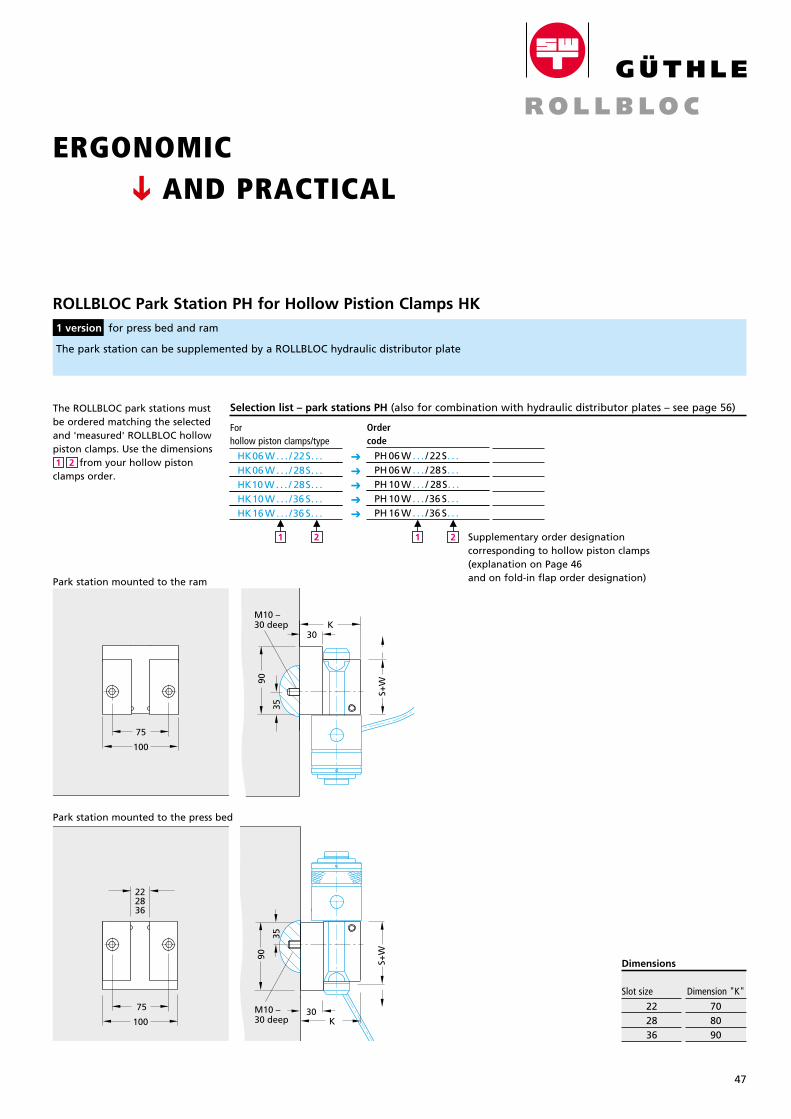
47
Breite: 65 mmStrichstärke: 0,3mmGröße wie Katalog
ROLLBLOC Park Station PH for Hollow Pistion Clamps HK
1 version for press bed and ram
The park station can be supplemented by a ROLLBLOC hydraulic distributor plate
35
90
75
S+W
M10 –30 deep
30K
M10 –30 deep
90
30K
35
S+W
100
75
100
222836
35
90
75
S+W
M10 –30 deep
30K
M10 –30 deep
90
30K
35
S+W
100
75
100
222836
35
90
75
S+W
M10 –30 deep
30K
M10 –30 deep
90
30K
35
S+W
100
75
100
222836
35
90
75
S+W
M10 –30 deep
30K
M10 –30 deep
90
30K
35
S+W
100
75
100
222836
Selection list – park stations PH (also for combination with hydraulic distributor plates – see page 56)
CSPACE-SAVING CLAMPING FOR DIES WITH CLAMPING SLOTS
ERGONOMIC AND PRACTICAL
Slot size
222836
Dimension "K"
708090
Dimensions
Park station mounted to the ram
Park station mounted to the press bed
C
For hollow piston clamps/type
HK06 W . . . / 22S. . . HK06 W . . . / 28S. . . HK10 W . . . / 28S. . . HK10 W . . . /36 S. . . HK16 W . . . /36 S. . .
M
2
M
1
C
C
C
C
C
Preis DMpro Stück
8
Ordercode
PH 06 W . . . / 22S. . . PH 06 W . . . / 28S. . . PH 10 W . . . / 28S. . . PH 10 W . . . /36 S. . . PH 16 W . . . /36 S. . .
M
2
M
1 Supplementary order designation corresponding to hollow piston clamps (explanation on Page 46 and on fold-in flap order designation)
The ROLLBLOC park stations must be ordered matching the selected and 'measured' ROLLBLOC hollow piston clamps. Use the dimensions from your hollow piston clamps order.
21
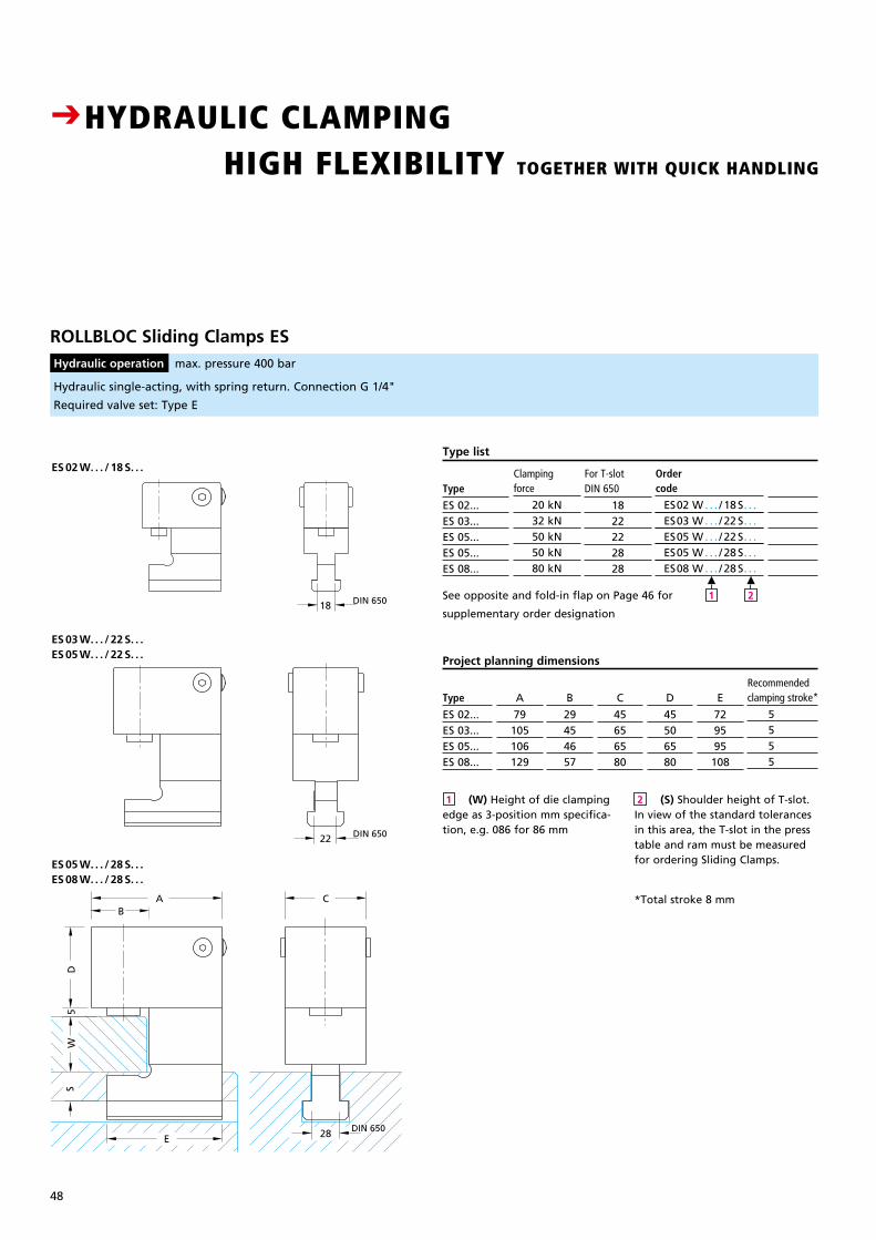
48
ROLLBLOC Sliding Clamps ES Hydraulic operation max. pressure 400 bar
Clampingforce
20 kN32 kN50 kN50 kN80 kN
DIN 650
1822222828
Ordercode
ES02 W . . . / 18 S. . . ES03 W . . . / 22 S. . . ES05 W . . . / 22 S. . . ES05 W . . . / 28 S. . . ES08 W . . . / 28 S. . .
Type list
Type
ES 02... ES 03...ES 05...ES 05...ES 08...
Preis DMpro Stück
8
Hydraulic single-acting, with spring return. Connection G 1/4"
Required valve set: Type E
For T-slot
SW
A
E
DIN 65022
DIN 650
CB
28
D5
DIN 65018
SW
A
E
DIN 65022
DIN 650
CB
28
D5
DIN 65018
SW
A
E
DIN 65022
DIN 650
CB
28
D5
DIN 65018
ES 03 W. . . / 22 S. . .ES 05 W. . . / 22 S. . .
ES 02 W. . . / 18 S. . .
ES 05 W. . . / 28 S. . .ES 08 W. . . / 28 S. . .
CHYDRAULIC CLAMPING HIGH FLEXIBILITY TOGETHER WITH QUICK HANDLING
M
2
M
1See opposite and fold-in flap on Page 46 for
supplementary order designation
C
45656580
B
29454657
A
79105106129
Type
ES 02... ES 03...ES 05...ES 08...
D
45506580
E
729595108
Recommended clamping stroke*
5 5 5 5
Project planning dimensions
(W) Height of die clamping edge as 3-position mm specifica- tion, e.g. 086 for 86 mm
(S) Shoulder height of T-slot. In view of the standard tolerances in this area, the T-slot in the press table and ram must be measured for ordering Sliding Clamps.
*Total stroke 8 mm
21
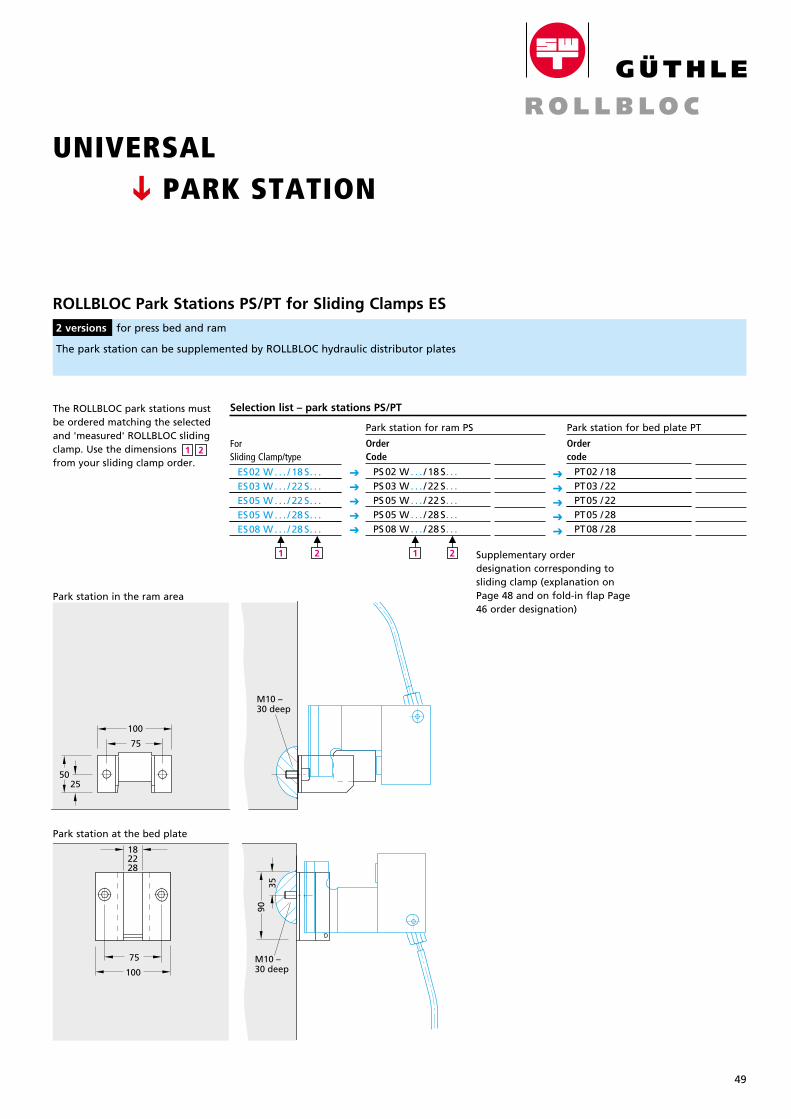
49
Breite: 65 mmStrichstärke: 0,3mmGröße wie Katalog
UNIVERSAL PARK STATION
Ordercode
PT02 / 18 PT03 / 22 PT05 / 22 PT05 / 28 PT08 / 28
Preis DMpro Stück
8
ROLLBLOC Park Stations PS/PT for Sliding Clamps ES 2 versions for press bed and ram
ForSliding Clamp/type
ES02 W . . . / 18 S. . . ES03 W . . . / 22 S. . . ES05 W . . . / 22 S. . . ES05 W . . . / 28 S. . . ES08 W . . . / 28 S. . .
Park station for bed plate PT
Selection list – park stations PS/PT
The park station can be supplemented by ROLLBLOC hydraulic distributor plates
Park station for ram PS
C
C
C
C
C
C
C
C
C
C
Preis DMpro Stück
8
OrderCode
PS 02 W . . . / 18 S. . . PS 03 W . . . / 22 S. . . PS 05 W . . . / 22 S. . . PS 05 W . . . / 28 S. . . PS 08 W . . . / 28 S. . .
100
75
5025
M10 –30 deep
100
75
5025
M10 –30 deep
Park station in the ram area
M
2
M
1
M
2
M
1 Supplementary order designation corresponding to sliding clamp (explanation on Page 48 and on fold-in flap Page 46 order designation)
C
The ROLLBLOC park stations must be ordered matching the selected and 'measured' ROLLBLOC sliding clamp. Use the dimensions from your sliding clamp order.
21
100
75
9030
30
9035
M10 –30 tief
75
100
M10 –30 deep
182228
100
75
9030
30
9035
M10 –30 tief
75
100
M10 –30 deep
182228
Park station at the bed plate
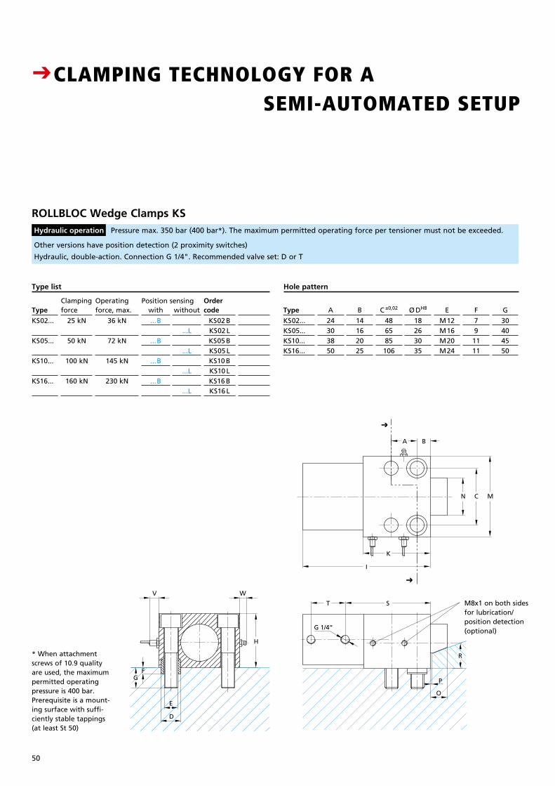
50
Hole pattern
Type
KS02...KS05...KS10...KS16...
A
24303850
B
14162025
C ±0,02
486585106
Ø DH8
18263035
E
M12M16M20M24
F
791111
G
30404550
ROLLBLOC Wedge Clamps KS Hydraulic operation Pressure max. 350 bar (400 bar*). The maximum permitted operating force per tensioner must not be exceeded.
Clampingforce
25 kN
50 kN
100 kN
160 kN
Operating force, max.
36 kN
72 kN
145 kN
230 kN
with
...B
...B
...B
...B
without
...L
...L
...L
...L
Ordercode
KS02 BKS02 LKS05 BKS05 LKS10 BKS10 LKS16 BKS16 L
Type list
Type
KS02...
KS05...
KS10...
KS16...
Preis DMpro Stck
8
Other versions have position detection (2 proximity switches)
Hydraulic, double-action. Connection G 1/4". Recommended valve set: D or T
Position sensing
CCLAMPING TECHNOLOGY FOR A SEMI-AUTOMATED SETUP
ST
R
P
O
G 1/4”
C MN
BA
I
K
W
H
V
D
E
FG
ST
R
P
O
G 1/4”
C MN
BA
I
K
W
H
V
D
E
FG
ST
R
P
O
G 1/4”
C MN
BA
I
K
W
H
V
D
E
FG
C
C
M8x1 on both sides for lubrication/position detection (optional)
* When attachment screws of 10.9 quality are used, the maximum permitted operating pressure is 400 bar. Prerequisite is a mount-ing surface with suffi-ciently stable tappings (at least St 50)
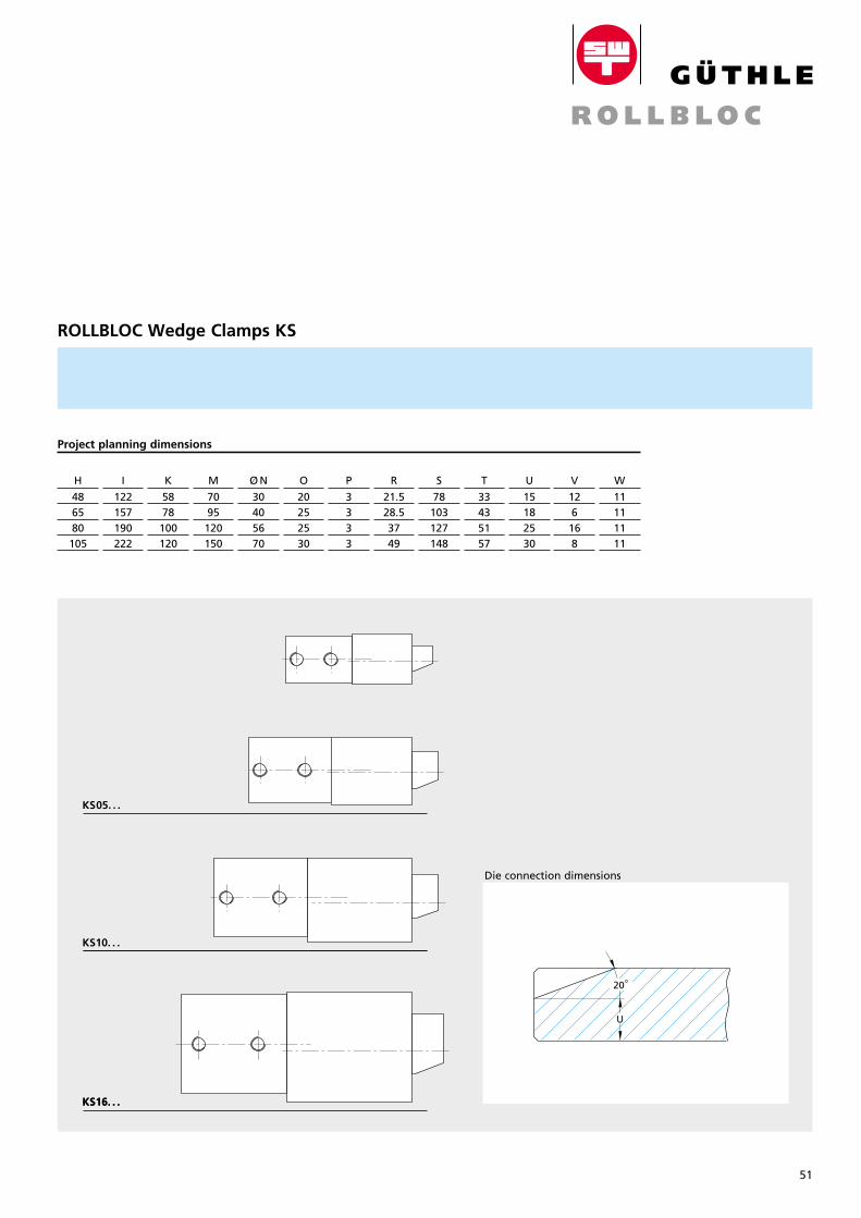
51
Breite: 65 mmStrichstärke: 0,3mmGröße wie Katalog
ROLLBLOC Wedge Clamps KS
Project planning dimensions
H
486580105
I
122157190222
K
5878100120
M
7095
120150
O
20252530
P
3333
R
21.528.53749
S
78103127148
T
33435157
U
15182530
V
126168
W
11111111
Die connection dimensions
20°
U
KS05. . .
KS10. . .
KS16. . .
CCLAMPING TECHNOLOGY FOR A SEMI-AUTOMATED SETUP
Ø N
30405670
M8x1 on both sides for lubrication/position detection (optional)
ST
R
P
O
G 1/4”
C MN
BA
I
K
W
H
V
D
E
FG
ST
R
P
O
G 1/4”
C MN
BA
I
K
W
H
V
D
E
FG
ST
R
P
O
G 1/4”
C MN
BA
I
K
W
H
V
D
E
FG
ST
R
P
O
G 1/4”
C MN
BA
I
K
W
H
V
D
E
FG
KS16. . .
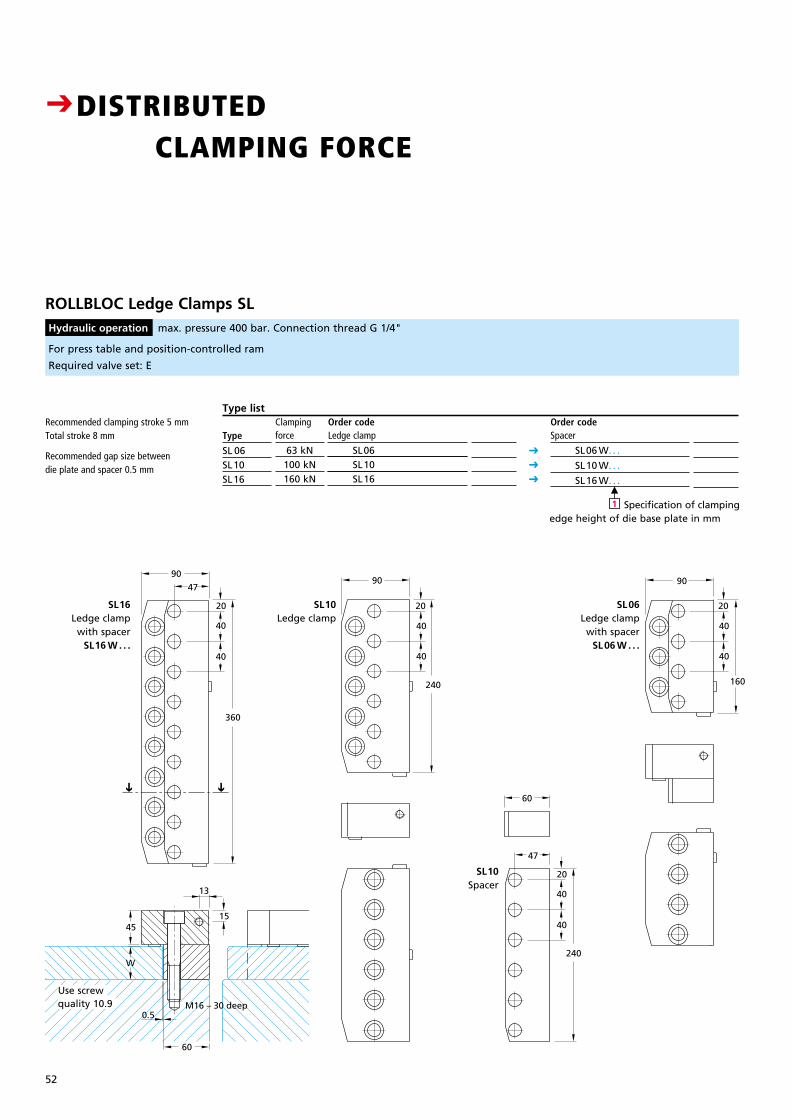
52
ROLLBLOC Ledge Clamps SL Hydraulic operation max. pressure 400 bar. Connection thread G 1/4"
For press table and position-controlled ram
Required valve set: E
Clamping force
63 kN100 kN160 kN
Order codeLedge clamp
SL06 SL10 SL16
Type list Type
SL 06 SL10SL16
Preis
8
Order codeSpacer
SL06 W. . .
SL10 W. . .
SL16 W. . .
Preis
8C
C
CM
1
160
40
40
20
90 9047
240
90
40
40
20
40
40
20
M16 – 30 deep
45
W
15
13
360
0.5
60
160
40
40
20
90 9047
240
90
40
40
20
40
40
20
M16 – 30 deep
45
W
15
13
360
0.5
60
160
40
40
20
90 9047
240
90
40
40
20
40
40
20
M16 – 30 deep
45
W
15
13
360
0.5
60
Recommended clamping stroke 5 mmTotal stroke 8 mm
Recommended gap size between die plate and spacer 0.5 mm
SL06Ledge clamp
with spacerSL06 W . . .
SL10Ledge clamp
SL16Ledge clamp
with spacerSL16 W . . .
Specification of clamping edge height of die base plate in mm
Use screw quality 10.9
160
40
40
20
90 90
240
40
40
20
M16 – 30 tief
45
W
15
13
47
90
40
40
20
360
0,5
60
47
40
40
20
240
60
SL10Spacer
CDISTRIBUTED CLAMPING FORCE
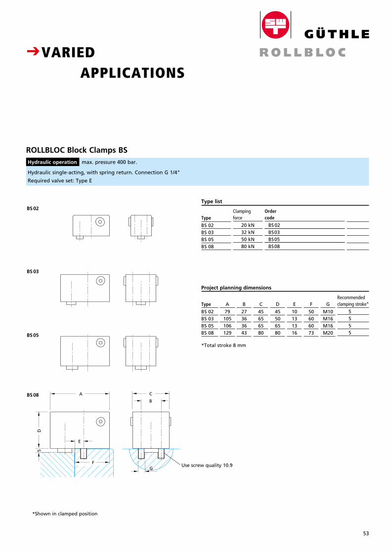
53
Breite: 65 mmStrichstärke: 0,3mmGröße wie Katalog
CVARIED APPLICATIONS
F
D5
A C
E
B
G
ROLLBLOC Block Clamps BS Hydraulic operation max. pressure 400 bar.
Clamping force
20 kN32 kN50 kN80 kN
Order code
BS 02 SS. . . BS03 BS05 BS08
Type list
Type
BS 02BS 03BS 05BS 08
Preis DMpro Stück
8
Type
BS 02BS 03BS 05BS 08
C
45656580
B
27363643
A
79105106129
D
45506580
E
10131316
F
50606073
G
M10M16M16M20
Recommended clamping stroke*
5 5 5 5
Project planning dimensions
Hydraulic single-acting, with spring return. Connection G 1/4"
Required valve set: Type E
*Total stroke 8 mm
*Shown in clamped position
BS 03
BS 02
BS 05
BS 08
Use screw quality 10.9
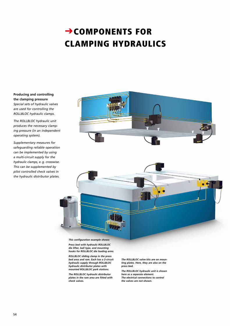
54
CCOMPONENTS FOR CLAMPING HYDRAULICS
Producing and controlling
the clamping pressure
Special sets of hydraulic valves
are used for controlling the
ROLLBLOC hydraulic clamps.
The ROLLBLOC hydraulic unit
produces the necessary clamp-
ing pressure (in an independent
operating system).
Supplementary measures for
safeguarding reliable operation
can be implemented by using
a multi-circuit supply for the
hydraulic clamps, e. g. crosswise.
This can be supplemented by
pilot controlled check valves in
the hydraulic distributor plates.
This configuration example shows:
Press bed with hydraulic ROLLBLOC die lifter, ball type, and mounting hooks for ROLLBLOC die loading arms.
ROLLBLOC sliding clamp in the press bed area and ram. Each has a 2-circuit hydraulic supply through ROLLBLOC hydraulic distributor plates with mounted ROLLBLOC park stations.
The ROLLBLOC hydraulic distributor plates in the ram area are fitted with check valves.
The ROLLBLOC valve kits are on moun-ting plates. Here, they are also on the press bed.
The ROLLBLOC hydraulic unit is shown here as a separate element. The electrical connections to control the valves are not shown.

55
Breite: 65 mmStrichstärke: 0,3mmGröße wie Katalog
Ordering and delivery
The hydraulic unit, hydraulic
valves and the optional mount-
ing plate are assigned separate
order numbers to facilitate
straight-forward ordering.
The equipment is supplied com-
pletely assembled and, depend-
ing on the ordered expansion
stage, wired on terminal strips
or additionally equipped with
a corresponding control system.
The prices for the valve sets
include the costs for functional
components, wiring and control.
Hose connections
for adaptive hydraulic clamps
Four standard hose lengths are
available. The measurement of
the length is usually based on
the smallest die. The inclusion
of a swivel connection is ad-
vantageous for handling the
clamps. In an additional type
the hoses can also be ordered
with an integrated quick-action
coupling.
ROLLBLOC hydraulic unit
The ROLLBLOC hydraulic unit
is mounted on an equipment
frame with a generously dimen-
sioned oil collection tray.
It accommodates the actual
hydraulic unit, normally to -
gether with valve sets and the
control cabinet (optional).
The hydraulic unit is sufficiently
dimensioned such as to be able
to supply 20 hollow piston
clamps (each with 160 kN
clamp ing force at 400 bar) for
example.
The valve sets are mounted on
the hydraulic unit.
Arranged on a separate valve
mounting plate, for mounting
in the ram area, the valve sets
can be placed in the vicinity of
the clamps. This arrange ment
effectively reduces the number
of moving hose connections
particularly in multi-circuit
applications in the ram area.
ROLLBLOC control valves
Directional seated valves
(24 V DC) of re no w n ed manu-
facturers are used for the
ROLLBLOC valve sets.
The valves are mounted on a
function block with hydraulic
test connections.
Valves with a ‚clamping‘
function are equipped with a
pres sure switch for function
monitoring.
Valve set: E. . .
Double-acting valve sets for
‚clamping‘ and ‚releasing‘ are
required for ROLLBLOC wedge
clamps. These valve sets are also
used for the park stations of
ROLLBLOC hollow piston clamps
and ROLL BLOC sliding clamps
which are equipped with pilot-
controlled check valve.
Valve set: D. . .
The following valve sets are
available for the pressure supply
of the ROLLBLOC die lifters:
Valve set: K. . .
For ROLLBLOC ball version
die lifters
(40 bar working pressure)
Valve set: W. . .
For ROLLBLOC roller version
die lifters
(80 bar working pressure)
ROLLBLOC hydraulic
distributor plate
Hydraulic distributor plates serve
primarily to branch the hydraulic
system to the adaptive clamps.
They also provide a solid base
for the pipes of the hydraulic
clamping system.
The hydraulic distributor plates
can also be supplied with pilot
controlled check valves to secure
the clamping force.
The hydraulic distributor plates
are also designed to be used as
replaceable base plates for the
park stations.
Park stations
In order that the adaptive clamps
have a defined place during die
changing, it is recommended
that appropriate park stations
are included. This avoids the
risks of collisions and, if neces-
sary, the clamps can also remain
in the park stations during pro-
duction. The park stations are
designed so that they can be
mounted directly on a hydraulic
distributor plate or they can
replace its base plate.
When ordering, please note:
Park stations should always
be ordered together with the
relevant clamps. Park stations
and distributor plates should
be ordered separately (even if
they are later to be combined).
PRELIMINARY INFORMATION FOR PROJECT PLANNING AND ORDERING
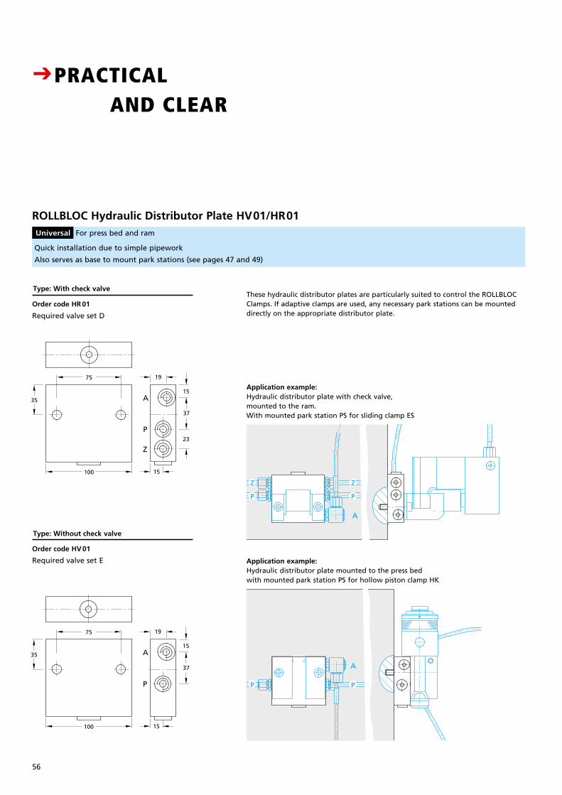
56
Type: With check valve
Order code HR 01
Required valve set D
CPRACTICAL AND CLEAR
15
35
100 15
75 19
37
23
A
P
Z
15
35
100 15
75 19
37
A
P
ROLLBLOC Hydraulic Distributor Plate HV01/HR01 Universal For press bed and ram
Quick installation due to simple pipework
Also serves as base to mount park stations (see pages 47 and 49)
A
A
P
Z
P
Z
A
A
P
Z
P
Z
A
A
P
Z
P
Z
A
A
P
Z
P
Z
Order code HV 01
Required valve set E Application example:Hydraulic distributor plate mounted to the press bedwith mounted park station PS for hollow piston clamp HK
15
35
100 15
75 19
37
23
A
P
Z
15
35
100 15
75 19
37
A
P
Application example:Hydraulic distributor plate with check valve, mounted to the ram. With mounted park station PS for sliding clamp ES
These hydraulic distributor plates are particularly suited to control the ROLLBLOC Clamps. If adaptive clamps are used, any necessary park stations can be mounted directly on the appropriate distributor plate.
Type: Without check valve
Z
P
Z
P
PP
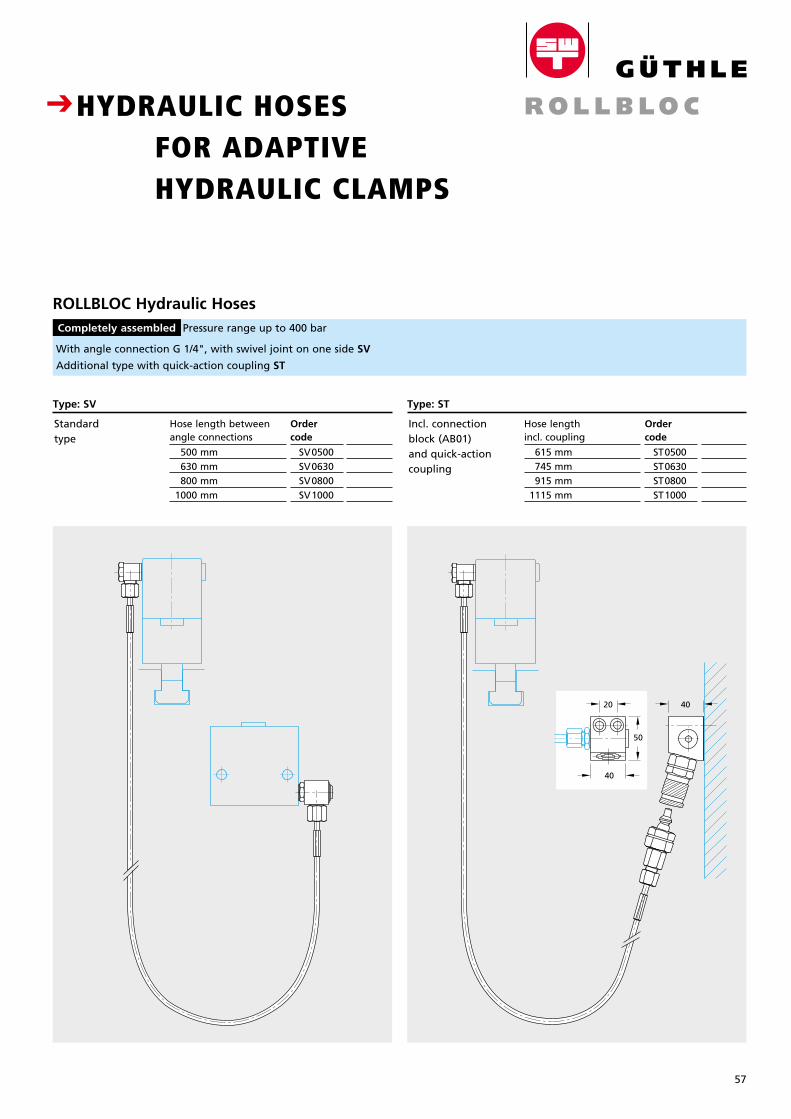
57
Breite: 65 mmStrichstärke: 0,3mmGröße wie Katalog
CHYDRAULIC HOSES FOR ADAPTIVE HYDRAULIC CLAMPS
ROLLBLOC Hydraulic Hoses Completely assembled Pressure range up to 400 bar
With angle connection G 1/4", with swivel joint on one side SV
Additional type with quick-action coupling ST
PreisDM
440.–145.–195.–230.–
Hose length between angle connections
500 mm 630 mm 800 mm 1000 mm
Ordercode
SV0500 SV0630 SV0800 SV1000
Standard type
Type: SV
PreisDM
440.–145.–195.–230.–
Hose length incl. coupling
615 mm 745 mm 915 mm 1115 mm
Ordercode
ST0500 ST0630 ST0800 ST1000
Incl. connection block (AB01) and quick-actioncoupling
Type: ST
4020
40
50
4020
40
50
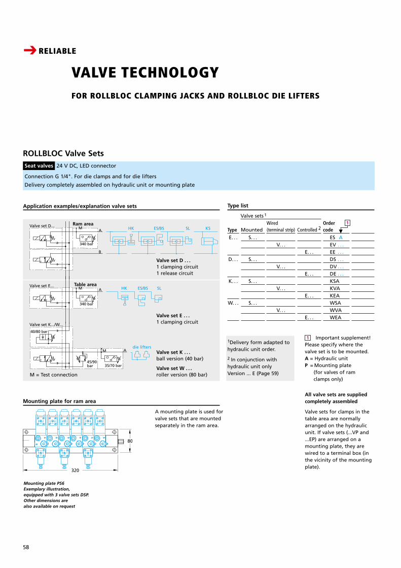
58
Connection G 1/4". For die clamps and for die lifters
Delivery completely assembled on hydraulic unit or mounting plate
ROLLBLOC Valve Sets Seat valves 24 V DC, LED connector
CRELIABLE
VALVE TECHNOLOGY FOR ROLLBLOC CLAMPING JACKS AND ROLLBLOC DIE LIFTERS
Ram area
Table area
M = Test connection
T P
Valve set K.../W...
Valve set D...
Valve set E...
340 bar
340 bar
A
A
B
HK ES/BS SL KS
HK ES/BS SL
M
M
40/80 bar
45/90bar 35/70 bar
die liftersAM
Aggregat A
V M3~
400 bar
370 bar
T P
Valve set K.../W...
Valve set D...
Valve set E...
340 bar
340 bar
A
A
B
HK ES/BS SL KS
HK ES/BS SL
M
M
40/80 bar
45/90bar 35/70 bar
die liftersAM
Aggregat A
V M3~
400 bar
370 bar
Application examples/explanation valve sets
Valve set W . . . roller version (80 bar)
Valve set K . . . ball version (40 bar)
Valve set E . . . 1 clamping circuit
Valve set D . . . 1 clamping circuit1 release circuit
Mounted
S. . .
S. . .
S. . .
S. . .
Type
E. . .
D. . .
K. . .
W. . .
Wired (terminal strip)
V. . .
V. . .
V. . .
V. . .
Controlled 2
E. . .
E. . .
E. . .
E. . .
Ordercode
ES A EV . . . EE . . . DS . . . DV . . . DE . . . KSA KVA KEA WSA WVA WEA
Type list
Valve sets 1
Important supplement!Please specify where the valve set is to be mounted.A = Hydraulic unitP = Mounting plate (for valves of ram clamps only)
1
All valve sets are suppliedcompletely assembled
Valve sets for clamps in the table area are normally arranged on the hydraulic unit. If valve sets (...VP and ...EP) are arranged on a mounting plate, they are wired to a terminal box (in the vicinity of the mounting plate).
1Delivery form adapted to hydraulic unit order.
2 In conjunction with hydraulic unit onlyVersion ... E (Page 59)
M
1T P
Valve set K.../W...
Valve set D...
Valve set E...
340 bar
340 bar
A
A
B
HK ES/BS SL KS
HK ES/BS SL
M
M
40/80 bar
45/90bar 35/70 bar
die liftersAM
Aggregat A
V M3~
400 bar
370 bar
Mounting plate for ram area
320
80
A mounting plate is used for valve sets that are mounted separately in the ram area.
Mounting plate PS6 Exemplary illustration,equipped with 3 valve sets DSP.Other dimensions are also available on request
58
Connection G 1/4". For die clamps and for die lifters
Delivery completely assembled on hydraulic unit or mounting plate
ROLLBLOC Valve SetsSeat valves 24 V DC, LED connector
CRELIABLE
VALVE TECHNOLOGY FOR ROLLBLOC CLAMPING JACKS AND ROLLBLOC DIE LIFTERS
Ram area
Table area
M = Test connection
Valve set K.../W...
40/80 bar
45/90bar 35/70 bar
die liftersAM
Valve set E...
340 bar
A HK ES/BS SLM
Important supplement!Please specify where thevalve set is to be mounted.A = Hydraulic unitP = Mounting plate
(for valves of ram clamps only)
Application examples/explanation valve sets
Valve set W . . .roller version (80 bar)
Valve set K . . .ball version (40 bar)
Valve set E . . .1 clamping circuit
Valve set D . . .1 clamping circuit1 release circuit
Mounted
S. . .
S. . .
S. . .
S. . .
Type
E. . .
D. . .
K. . .
W. . .
Wired (terminal strip)
V. . .
V. . .
V. . .
V. . .
Controlled 2
E. . .
E. . .
E. . .
E. . .
Ordercode
ES AEV . . .EE . . .DS . . .DV . . .DE . . .KSAKVAKEAWSAWVAWEA
Type list
Valve sets 1
1
All valve sets are suppliedcompletely assembled
Valve sets for clamps in thetable area are normallyarranged on the hydraulicunit. If valve sets (...VP and...EP) are arranged on amounting plate, they arewired to a terminal box (inthe vicinity of the mountingplate).
1Delivery form adapted tohydraulic unit order.
2 In conjunction with hydraulic unit onlyVersion ... E (Page 59)
�
1Valve set D...
340 bar
A
B
HK ES/BS SL KSM
Mounting plate for ram area
320
80
A mounting plate is used for valve sets that are mounted separately in the ram area.
Mounting plate PS6 Exemplary illustration,equipped with 3 valve sets DSP.Other dimensions are also available on request
2356LZ_Katalog 09_gb:0335LZ1K Katalog 30.09.2009 16:42 Uhr Seite 64
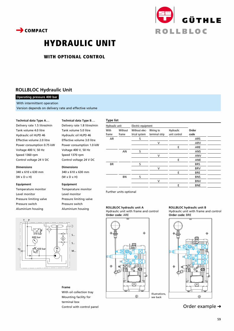
59
Breite: 65 mmStrichstärke: 0,3mmGröße wie Katalog
C
With intermittent operation
Version depends on delivery rate and effective volume
ROLLBLOC Hydraulic Unit
Operating pressure 400 bar
Technical data Type B. . .
Delivery rate 1.8 litres/min
Tank volume 5.0 litre
Hydraulic oil HLPD 46
Effective volume 3.0 litre
Power consumption 1.0 kW
Voltage 400 V, 50 Hz
Speed 1370 rpm
Control voltage 24 V DC
Dimensions
340 x 610 x 630 mm
(W x D x H)
Equipment
Temperature monitor
Level monitor
Pressure limiting valve
Pressure switch
Aluminium housing
Technical data Type A. . .
Delivery rate 1.5 litres/min
Tank volume 4.0 litre
Hydraulic oil HLPD 46
Effective volume 2.0 litre
Power consumption 0.75 kW
Voltage 400 V, 50 Hz
Speed 1360 rpm
Control voltage 24 V DC
Dimensions
340 x 610 x 630 mm
(W x D x H)
Equipment
Temperature monitor
Level monitor
Pressure limiting valve
Pressure switch
Aluminium housing
24.05.2006BRV-1DVA-1KVA
24.05.2006ARV-1EVA-1KVA
CCOMPACT
HYDRAULIC UNIT WITH OPTIONAL CONTROL
Without frame
AN
BN
With frame
AR
BR
Hydraulicunit control
E
E
E
E
Without elec-trical system
S
S
S
S
Ordercode
ARS ARV ARE ANS ANV ANE BRS BRV BRE BNS BNV BNE
Wiring toterminal strip
V
V
V
V
Type list
Hydraulic unit Electric equipment
Further units optional
Order exampleC
ROLLBLOC hydraulic unit AHydraulic unit with frame and controlOrder code: ARE
ROLLBLOC hydraulic unit BHydraulic unit with frame and controlOrder code: BRE
Frame
With oil collection tray
Mounting facility for
terminal box
Control with control panel
A
B
WH1R
WH1N
A = SpannenB = Lösen
340 bar
340 bar
SlipGrip
T P
T P
370 bar600 bar
420 barT2 M3~ M...
S...
S...
V
Illustrations, see back
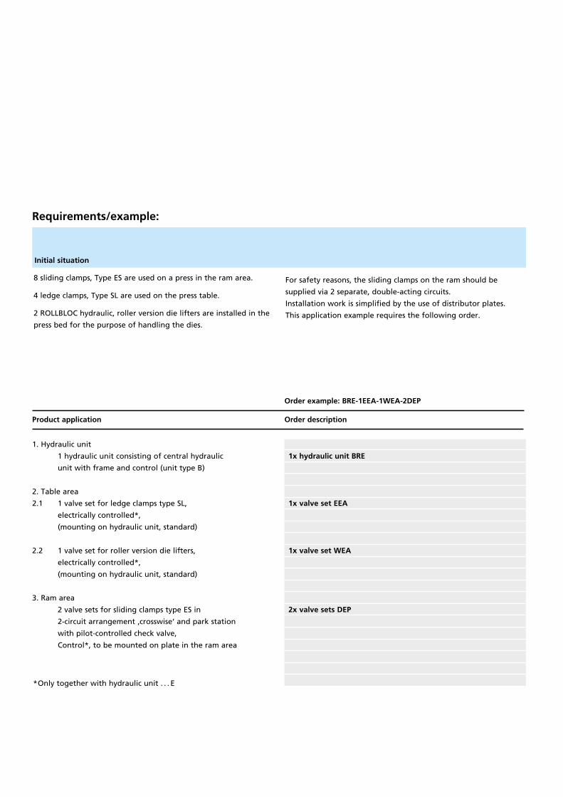
1. Hydraulic unit
1 hydraulic unit consisting of central hydraulic
unit with frame and control (unit type B)
2. Table area
2.1 1 valve set for ledge clamps type SL,
electrically controlled*,
(mounting on hydraulic unit, standard)
2.2 1 valve set for roller version die lifters,
electrically controlled*,
(mounting on hydraulic unit, standard)
3. Ram area
2 valve sets for sliding clamps type ES in
2-circuit arrangement ‚crosswise‘ and park station
with pilot-controlled check valve,
Control*, to be mounted on plate in the ram area
Product application Order description
Order example: BRE-1EEA-1WEA-2DEP
*Only together with hydraulic unit . . . E
Requirements/example:
8 sliding clamps, Type ES are used on a press in the ram area.
4 ledge clamps, Type SL are used on the press table.
2 ROLLBLOC hydraulic, roller version die lifters are installed in the
press bed for the purpose of handling the dies.
For safety reasons, the sliding clamps on the ram should be
supplied via 2 separate, double-acting circuits.
Installation work is simplified by the use of distributor plates.
This application example requires the following order.
Initial situation
1x hydraulic unit BRE
1x valve set EEA
1x valve set WEA
2x valve sets DEP
C CARRYING C MOVING C CLAMPING
Breite: 65 mmStrichstärke: 0,3mmGröße wie Katalog
�
C HIGH-QUALITY COMPONENTS FOR RELIABLE FUNCTIONALITY
RB-GB-102016Errors and omission excepted,subject to technical modifications.All measures in mm.
Hydraulic die clamping withROLLBLOC sliding clamps
Fast and reliable die transferbetween ROLLBLOC-BUGGY
and press table, equippedwith ROLLBLOC die lifters
Automated die changing with thetrack-mounted die transporterDILOS SHUTTLE. Separate productinformation is available on theGÜTHLE DILOS range.
Safe and reliable die changingwith ROLLBLOC die loading armsand ROLLBLOC die lifters
Hydraulic valves to control theROLLBLOC clamps and ROLLBLOC die lifterson mounting plate
ROLLBLOC Hydraulic Unit (Rear Side)with pump and control valveswith frame structure
ROLLBLOC Hydraulic Unitwith operating panel and controls
QUICK DIE CHANGE
GÜ
TH
LE P
RE
SS
EN
SP
AN
NE
N G
MB
HR
OLL
BLO
C P
RO
DU
CT
-CA
TA
LOG
UE
ED
ITIO
N 5
Güthle Pressenspannen GmbHGottlieb-Haefele-Strasse 9
73061 Ebersbach
GERMANY
Phone: +49 7163 99090
Fax: +49 7163 990990
www.guthle.com
Breite: 65 mmStrichstärke: 0,3mmGröße wie Katalog
Breite: 65 mmStrichstärke: 0,3mmGröße wie Katalog
IDEA AND SYSTEMS
ROLLBLOC PRODUCT CATALOGUE
IDEA AND SYSTEMS
Breite: 65 mmStrichstärke: 0,3mmGröße wie KatalogCHANGING TECHNOLOGY