Embed Size (px)
Citation preview
Büro für Tragwerksplanung und Ingenieurbau
vom Felde + Keppler GmbH & Co. KG
Lütticher Straße 10-12 Telefon: 0241 / 70 96 96 52064 Aachen Telefax: 0241 / 70 96 46 www.vom-felde.de [email protected]
Kurzfassung der Statischen Berechnung F34 Abstract of the Structural Report
für das System der Firma for the system by
Global Truss Furong Industrial Area Shajing Town Baoan District Shenzen China Aufgestellt: Aachen, 20.11.2014 compiled by:
Diese statische Berechnung umfasst die Seiten 1 - 22 This Structural Report includes pages
Diese statische Berechnung ist ausschließlich aufgestellt für die Firma Global Truss. Eine Weitergabe an Dritte ist nur mit vorheriger Genehmigung des Aufstellers möglich. This Structural Report is set up exclusively for the company Global Truss. Forwarding to third parties only with the author’s approval.
Büro für Tragwerksplanung und Ingenieurbau
vom Felde + Keppler GmbH & Co. KG
Lütticher Straße 10-12
52064 Aachen
Telefon: 0241 / 70 96 96
Telefax: 0241 / 70 96 46
buero@vom- fe lde.de
INHALTSVERZEICHNIS Table of contents 1 VORBEMERKUNGEN / PRELIMINARY NOTES .............................................................................................1
1.1 Grundlagen / Basics ...................................................................................................................................1 1.2 Verwendete Baustoffe / Materials .............................................................................................................1 1.3 Allgemeine Beschreibung / General remarks ............................................................................................1 1.4 Geometrie und Belastung / Geometry and loadings ..................................................................................3
2 SYSTEM............................................................................................................................................................6 3 QUERSCHNITTS - UND MATERIALEIGENSCHAFTEN / SECTION- AND MATERIAL PORPERTIES .......7 4 ZULÄSSIGE BELASTUNGEN EINZELBAUTEILE / ALLOWABLE LOADING SINGLE COMPONENTS ......9 5 ZULÄSSIGE BELASTUNG EINFELDTRÄGER / ALLOWABLE LOADING SINGLE SPAN GIRDER .......... 12
5.1 Gleichlast vertikal (UDL) / Vertically uniformly distributed loads (UDL) .................................................. 12 5.2 Einzellast in Feldmitte / Single point load in 1/2 point ............................................................................. 13 5.3 Einzellasten in den Drittelspunkten / Single point load in 1/3 points ....................................................... 15 5.4 Einzellasten in den Viertelspunkten / Single point load in 1/4 points ...................................................... 17 5.5 Einzellasten in den Fünftelspunkten / Single point load in 1/5 points ..................................................... 19
6 ZUSAMMENFASSUNG DER ERGEBNISSE / SUMMARS OF RESULTS ................................................... 21
6.1 Zulässige Belastung / Allowable loading: ................................................................................................ 21 6.2 Vorhandene Durchbiegung unter max. Belastung / Deflection at allowable loading: ............................. 22
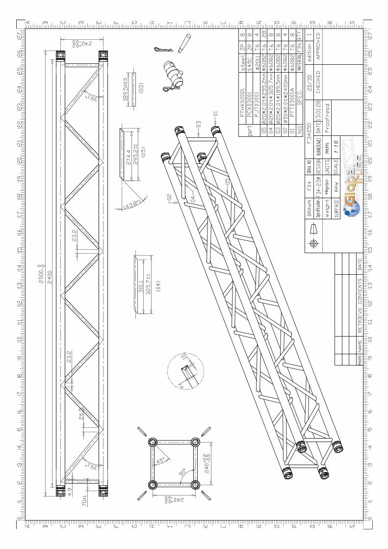
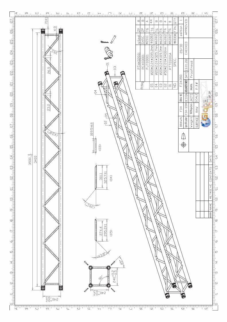
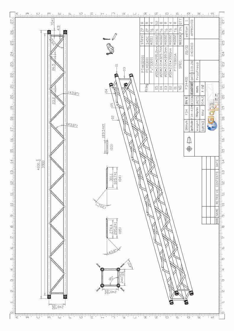
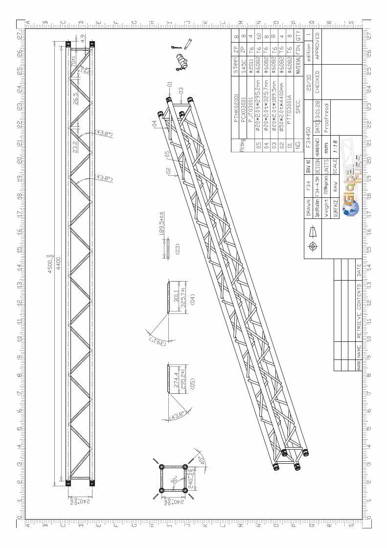
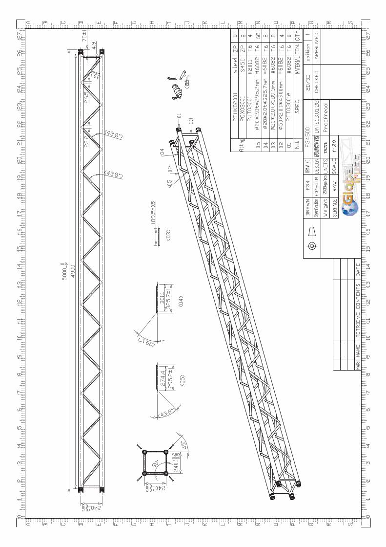
ANHÄNGE / ANNEXES . . . . . . . . . . . . . . . . . . . . . . . . . . . . . . . . . . . . . . . . . . Zeichnungen Systeme F34. . . . . . . . . . . . . . . . . . . . . . . . . . . . . . . Drawings F34
F34050-Model, F34100-Model, F34150-Model, F34200-Model, F34250-Model, F34300-Model, F34350-Model, F34400-Model, F34450-Model, F34500-Model
Büro für Tragwerksplanung und Ingenieurbau
vom Felde + Keppler GmbH & Co. KG
1
Lütticher Straße 10-12
52064 Aachen
Telefon: 0241 / 70 96 96
Telefax: 0241 / 70 96 46
buero@vom- fe lde.de
1 VORBEMERKUNGEN PRELIMINARY NOTES
1.1 Grundlagen
Basics Die z.Zt. gültigen Vorschriften und Normen, insbesondere: DIN EN 1991-1 Lastannahmen für Bauten (Eurocode 1) Actions on structures (Eurocode 1)
DIN EN 13814 Fliegende Bauten Fairground and amusement park machinery and structures
DIN EN 13782 Fliegende Bauten – Zelte Temporary Structures – Tents
DIN EN 1993-1 Bemessung und Konstruktion von Stahlbauten (Eurocode 3) Design of steel structures
DIN EN 1999-1 Bemessung und Konstruktion von Aluminiumtragwerken (Eurocode 9) Design of aluminium structures
1.2 Verwendete Baustoffe
Materials Rohre / Tubes Aluminium EN AW-6082 T6 Bolzen / Bolts Güte mind. 8.8 (grade min. 8.8)
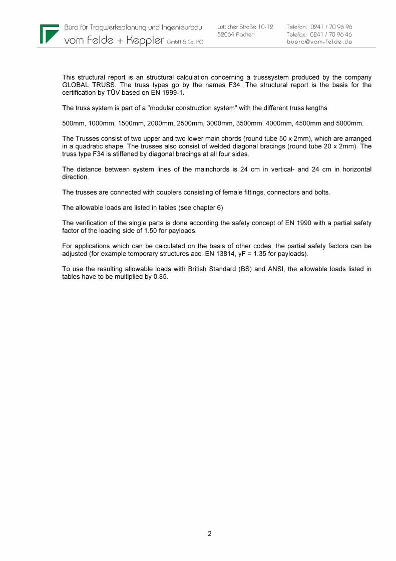
1.3 Allgemeine Beschreibung
General Remarks
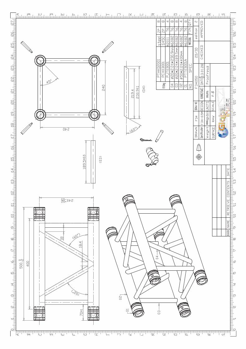
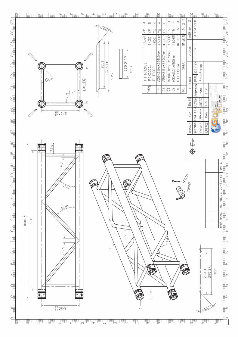
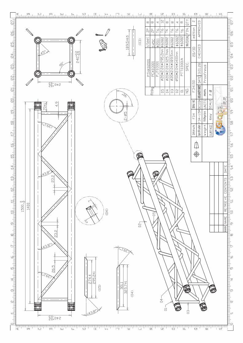
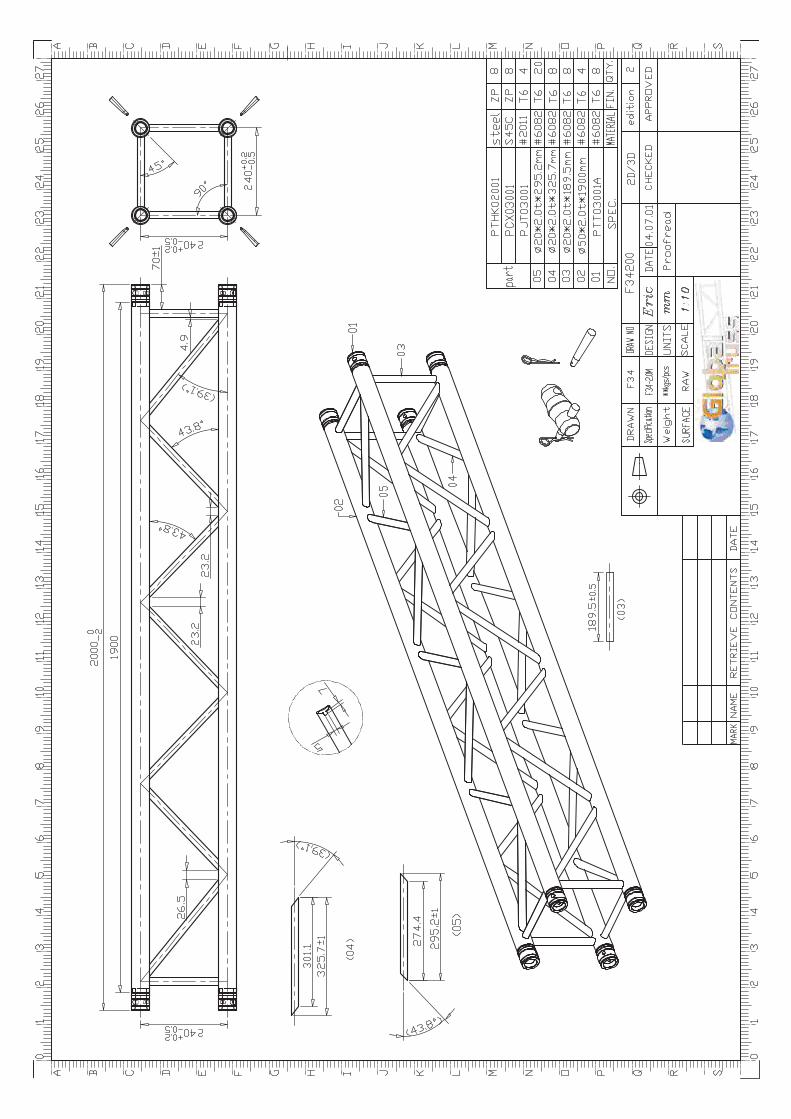
Diese statische Berechnung beinhaltet die Berechnung und die Nachweise eines Traversensystems, das von der Firma GLOBAL TRUSS hergestellt wird. Die Bezeichnung des Traversentyps lautet F34. Die Berechnung ist Grundlage für eine Bauartprüfung durch einen TÜV auf Grundlage der EN 1999-1. Es handelt sch um ein „Baukastensystem“ mit den folgenden möglichen Einzelelementlängen: 500mm, 1000mm, 1500mm, 2000mm, 2500mm, 3000mm, 3500mm, 4000mm, 4500mm and 5000mm. Die Traverse bestehen aus zwei Ober- bzw. Untergurten (Rundrohre 50 x 2mm), in quadratischer Anordnung und angeschweißten Diagonalstäben (Rundrohre 20 x 2mm). Die Diagonalstäbe werden in allen 4 Seiten angeordnet. Der Achsabstand der Gurtrohre beträgt 24 cm in vertikaler Richtung und 24 cm in horizontaler Richtung. Die Traversen werden über Kupplungen miteinander verbunden, die aus einer Hülse, einem Verbinder und Bolzen bestehen. Die zulässigen Belastungen sind in Tabellen aufgeführt (siehe Kapitel 6). Die Nachweise der Einzelbauteile erfolgen nach dem Sicherheitskonzept nach EN 1990 mit einem Teilsicherheitsbeiwert auf der Lastseite von yF = 1,50 für Nutzlasten. Bei Anwendungsfällen, die auf Grundlage anderer Normen berechnet werden, können die Teilsicherheitsbeiwerte auf der Lastseite angepasst werden (z.B. fliegende Bauten nach EN 13814, yF = 1,35 für Nutzlasten). Bei Anwendung des British Standard (BS) und des ANSI müssen die in den Tabellen aufgeführten zulässigen Belastungen mit dem Faktor 0,85 multipliziert werden.
Büro für Tragwerksplanung und Ingenieurbau
vom Felde + Keppler GmbH & Co. KG
2
Lütticher Straße 10-12
52064 Aachen
Telefon: 0241 / 70 96 96
Telefax: 0241 / 70 96 46
buero@vom- fe lde.de
This structural report is an structural calculation concerning a trusssystem produced by the company GLOBAL TRUSS. The truss types go by the names F34. The structural report is the basis for the certification by TÜV based on EN 1999-1. The truss system is part of a "modular construction system" with the different truss lengths 500mm, 1000mm, 1500mm, 2000mm, 2500mm, 3000mm, 3500mm, 4000mm, 4500mm and 5000mm. The Trusses consist of two upper and two lower main chords (round tube 50 x 2mm), which are arranged in a quadratic shape. The trusses also consist of welded diagonal bracings (round tube 20 x 2mm). The truss type F34 is stiffened by diagonal bracings at all four sides. The distance between system lines of the mainchords is 24 cm in vertical- and 24 cm in horizontal direction. The trusses are connected with couplers consisting of female fittings, connectors and bolts. The allowable loads are listed in tables (see chapter 6). The verification of the single parts is done according the safety concept of EN 1990 with a partial safety factor of the loading side of 1.50 for payloads. For applications which can be calculated on the basis of other codes, the partial safety factors can be adjusted (for example temporary structures acc. EN 13814, yF = 1.35 for payloads). To use the resulting allowable loads with British Standard (BS) and ANSI, the allowable loads listed in tables have to be multiplied by 0.85.
Büro für Tragwerksplanung und Ingenieurbau
vom Felde + Keppler GmbH & Co. KG
3
Lütticher Straße 10-12
52064 Aachen
Telefon: 0241 / 70 96 96
Telefax: 0241 / 70 96 46
buero@vom- fe lde.de
q
l
P
l/2 l/2
P P
l/3l/3 l/3
PPPPPP PPPPPPPPPPPP
l/4 l/4 l/4 l/4
l/5
P P P P
l/5 l/5 l/5 l/5
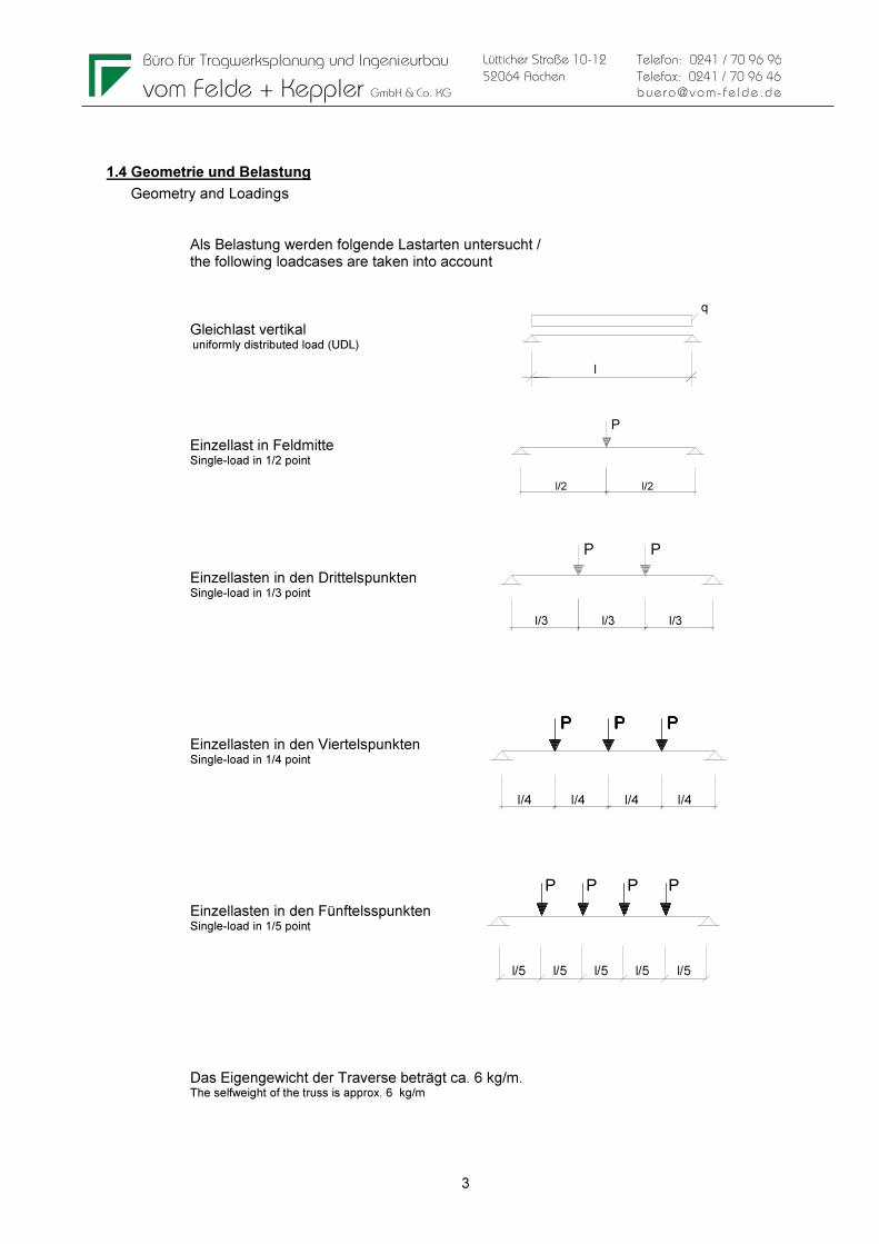
1.4 Geometrie und Belastung
Geometry and Loadings Als Belastung werden folgende Lastarten untersucht / the following loadcases are taken into account Gleichlast vertikal uniformly distributed load (UDL) Einzellast in Feldmitte Single-load in 1/2 point
Einzellasten in den Drittelspunkten Single-load in 1/3 point
Einzellasten in den Viertelspunkten Single-load in 1/4 point
Einzellasten in den Fünftelsspunkten Single-load in 1/5 point
Das Eigengewicht der Traverse beträgt ca. 6 kg/m. The selfweight of the truss is approx. 6 kg/m
Büro für Tragwerksplanung und Ingenieurbau
vom Felde + Keppler GmbH & Co. KG
4
Lütticher Straße 10-12
52064 Aachen
Telefon: 0241 / 70 96 96
Telefax: 0241 / 70 96 46
buero@vom- fe lde.de
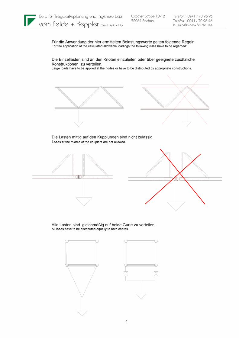
Für die Anwendung der hier ermittelten Belastungswerte gelten folgende Regeln: For the application of the calculated allowable loadings the following rules have to be regarded:
Die Einzellasten sind an den Knoten einzuleiten oder über geeignete zusätzliche Konstruktionen zu verteilen. Large loads have to be applied at the nodes or have to be distributed by appropriate constructions.
Die Lasten mittig auf den Kupplungen sind nicht zulässig. Loads at the middle of the couplers are not allowed. Alle Lasten sind gleichmäßig auf beide Gurte zu verteilen. All loads have to be distributed equally to both chords.
Büro für Tragwerksplanung und Ingenieurbau
vom Felde + Keppler GmbH & Co. KG
5
Lütticher Straße 10-12
52064 Aachen
Telefon: 0241 / 70 96 96
Telefax: 0241 / 70 96 46
buero@vom- fe lde.de
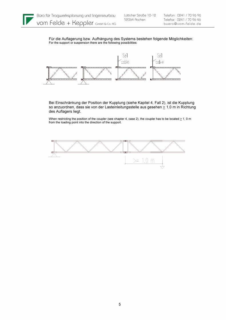
Für die Auflagerung bzw. Aufhängung des Systems bestehen folgende Möglichkeiten: For the support or suspension there are the following possibilities:
Bei Einschränkung der Position der Kupplung (siehe Kapitel 4, Fall 2), ist die Kupplung so anzuordnen, dass sie von der Lasteinleitungsstelle aus gesehen > 1,0 m in Richtung des Auflagers liegt. When restricting the position of the coupler (see chapter 4, case 2), the coupler has to be located > 1, 0 m from the loading point into the direction of the support.

Büro für Tragwerksplanung und Ingenieurbau
vom Felde + Keppler GmbH & Co. KG
6
Lütticher Straße 10-12
52064 Aachen
Telefon: 0241 / 70 96 96
Telefax: 0241 / 70 96 46
buero@vom- fe lde.de
2 SYSTEM
Zeichnungen Systeme F34 . . . . . . . . . . . . . . . . . . . . . . . . . . . . . . . . . . . . Drawings F34 F34050-Model, F34100-Model, F34150-Model, F34200-Model, F34250-Model, F34300-Model, F34350-Model, F34400-Model, F34450-Model, F34500-Model siehe Anhang see annex
Büro für Tragwerksplanung und Ingenieurbau
vom Felde + Keppler GmbH & Co. KG
7
Lütticher Straße 10-12
52064 Aachen
Telefon: 0241 / 70 96 96
Telefax: 0241 / 70 96 46
buero@vom- fe lde.de
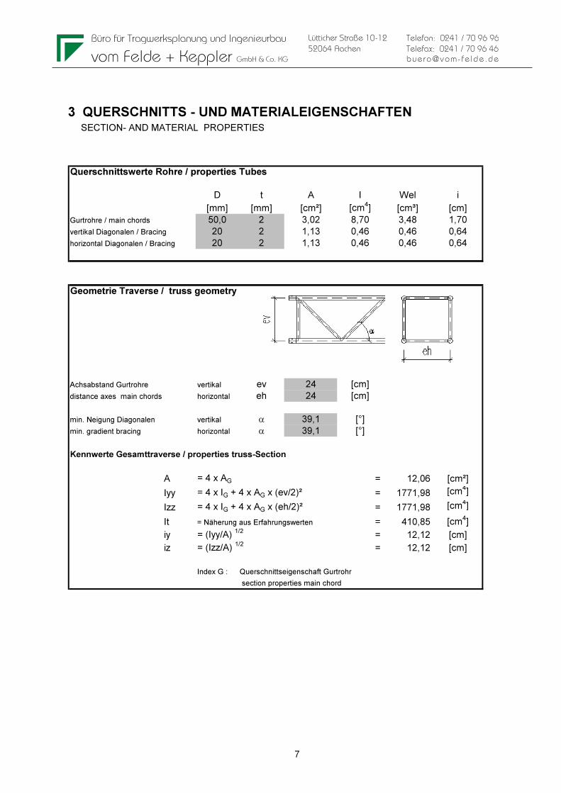
3 QUERSCHNITTS - UND MATERIALEIGENSCHAFTEN SECTION- AND MATERIAL PROPERTIES Querschnittswerte Rohre / properties Tubes
D t A I Wel i
[mm] [mm] [cm²] [cm4] [cm³] [cm]
Gurtrohre / main chords 50,0 2 3,02 8,70 3,48 1,70
vertikal Diagonalen / Bracing 20 2 1,13 0,46 0,46 0,64
horizontal Diagonalen / Bracing 20 2 1,13 0,46 0,46 0,64
Geometrie Traverse / truss geometry
Achsabstand Gurtrohre vertikal ev 24 [cm]
distance axes main chords horizontal eh 24 [cm]
min. Neigung Diagonalen vertikal α 39,1 [°]
min. gradient bracing horizontal α 39,1 [°]
Kennwerte Gesamttraverse / properties truss-Section
A = 4 x AG = 12,06 [cm²]
Iyy = 4 x IG + 4 x AG x (ev/2)² = 1771,98 [cm4]
Izz = 4 x IG + 4 x AG x (eh/2)² = 1771,98 [cm4]
It = Näherung aus Erfahrungswerten = 410,85 [cm4]
iy = (Iyy/A) 1/2
= 12,12 [cm]
iz = (Izz/A) 1/2
= 12,12 [cm]
Index G : Querschnittseigenschaft Gurtrohr
section properties main chord
Büro für Tragwerksplanung und Ingenieurbau
vom Felde + Keppler GmbH & Co. KG
8
Lütticher Straße 10-12
52064 Aachen
Telefon: 0241 / 70 96 96
Telefax: 0241 / 70 96 46
buero@vom- fe lde.de
Materialeigenschaften Material properties
Gurtrohre + Diagonalen EN AW 6082 T6 (AlMgSi1)
chords and bracing
zulässige Spannungen nach EN-1999-1-1 / allowable stress acc. to EN-1999-1-1
Teilsicherheitsbeiwerte Material / partial safety factors material
YM1 1,10 Beulklasse / BC A
YM2 1,25
0,2%-Dehngrenze / 0,2%-Proof Strength Zugfestigkeit / ultimate tensile strength
fo t=5mm 250 [N/mm²] fu t=5mm 290 [N/mm²]
fo t>5mm 260 [N/mm²] fu t>5mm 310 [N/mm²]
fo,haz 125 [N/mm²] fu,haz 185 [N/mm²]
Festigkeit der Schweißnaht fw 190 [N/mm²]
Strength of welding seams
Faktor für die WEZ-Werte beim WIG-Schweißen: 0,8
Factor for HAZ-values for TIG-welding:
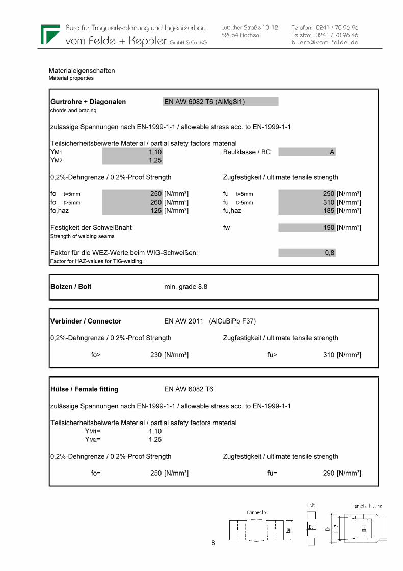
Bolzen / Bolt min. grade 8.8
Verbinder / Connector EN AW 2011 (AlCuBiPb F37)
0,2%-Dehngrenze / 0,2%-Proof Strength Zugfestigkeit / ultimate tensile strength
fo> 230 [N/mm²] fu> 310 [N/mm²]
Hülse / Female fitting EN AW 6082 T6
zulässige Spannungen nach EN-1999-1-1 / allowable stress acc. to EN-1999-1-1
Teilsicherheitsbeiwerte Material / partial safety factors material
YM1= 1,10
YM2= 1,25
0,2%-Dehngrenze / 0,2%-Proof Strength Zugfestigkeit / ultimate tensile strength
fo= 250 [N/mm²] fu= 290 [N/mm²]
Büro für Tragwerksplanung und Ingenieurbau
vom Felde + Keppler GmbH & Co. KG
9
Lütticher Straße 10-12
52064 Aachen
Telefon: 0241 / 70 96 96
Telefax: 0241 / 70 96 46
buero@vom- fe lde.de
Gurtrohr im Bereich der WEZ an der Kupplung
main chord in heat affected zone at coupler
NRd =A x 0,8* x fu,haz / YM2= 35,71 [kN] *(WIG TIG)
örtliche Schweißnaht nach Kap. 6.2.9.3 (1)
local w elding seam acc. chapter 6.2.9.3 (1)
Diagonale im Bereich der WEZ
bracing in heat affected zone
NRd = A x 0,8* x fu,haz / YM2= 13,39 [kN] *(WIG TIG)
örtliche Schweißnaht nach Kap. 6.2.9.3 (1)
local w elding seam acc. chapter 6.2.9.3 (1)
4 ZULÄSSIGE BELASTUNGEN EINZELBAUTEILE ALLOWABLE LOADING SINGLE COMPONENTS In dieser Kurzfassung werden nur die maßgebenden zulässigen Beanspruchungen aufgeführt. Die Berechnung der zulässigen Beanspruchung aller Bauteile erfolgt in der Statischen Berechnung 14905 vom 08.08.2014. In this abstract only the relevant allowable loadings are mentioned. The calculation of the allowable loadings of all parts is done in the Structural Report 14905 from 08.08.2014.
Maßgebend für die Ermittlung der zulässigen Belastungen sind folgende Punkte: Following points are relevant for the determination of the allowable loads:
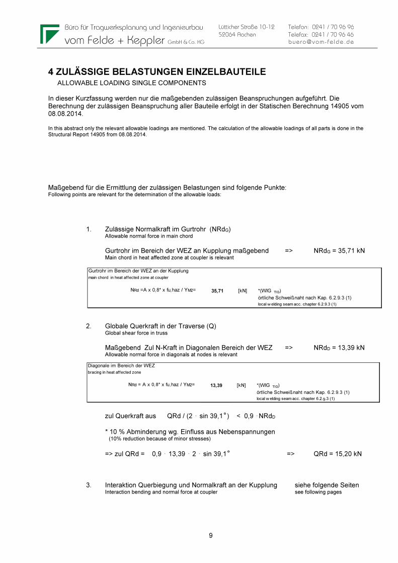
1. Zulässige Normalkraft im Gurtrohr (NRdG) Allowable normal force in main chord
Gurtrohr im Bereich der WEZ an Kupplung maßgebend => NRdG = 35,71 kN Main chord in heat affected zone at coupler is relevant
2. Globale Querkraft in der Traverse (Q) Global shear force in truss
Maßgebend Zul N-Kraft in Diagonalen Bereich der WEZ => NRdD = 13,39 kN Allowable normal force in diagonals at nodes is relevant
zul Querkraft aus QRd / (2 ⋅ sin 39,1 ̊ ) < 0,9 ⋅NRdD * 10 % Abminderung wg. Einfluss aus Nebenspannungen (10% reduction because of minor stresses)
=> zul QRd = 0,9 ⋅ 13,39 ⋅ 2 ⋅ sin 39,1 ̊ => QRd = 15,20 kN 3. Interaktion Querbiegung und Normalkraft an der Kupplung siehe folgende Seiten Interaction bending and normal force at coupler see following pages
Büro für Tragwerksplanung und Ingenieurbau
vom Felde + Keppler GmbH & Co. KG
10
Lütticher Straße 10-12
52064 Aachen
Telefon: 0241 / 70 96 96
Telefax: 0241 / 70 96 46
buero@vom- fe lde.de
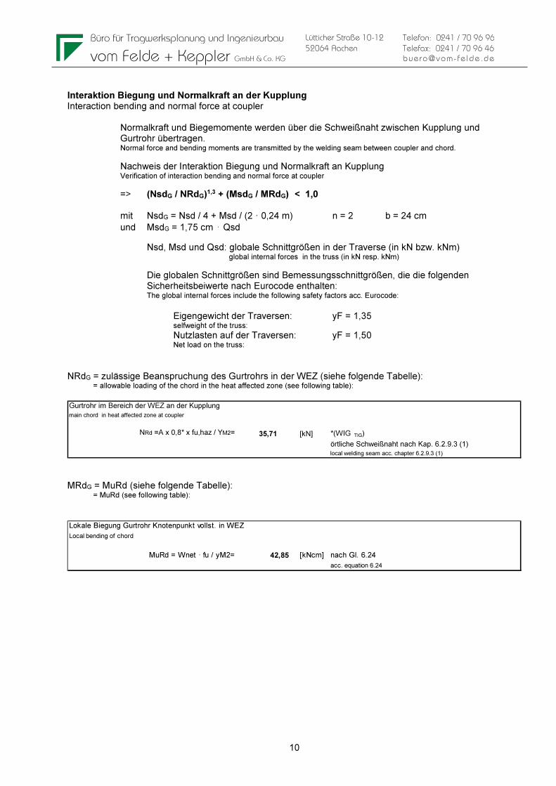
Interaktion Biegung und Normalkraft an der Kupplung Interaction bending and normal force at coupler
Normalkraft und Biegemomente werden über die Schweißnaht zwischen Kupplung und Gurtrohr übertragen. Normal force and bending moments are transmitted by the welding seam between coupler and chord.
Nachweis der Interaktion Biegung und Normalkraft an Kupplung Verification of interaction bending and normal force at coupler
=> (NsdG / NRdG)1,3 + (MsdG / MRdG) < 1,0 mit NsdG = Nsd / 4 + Msd / (2 · 0,24 m) n = 2 b = 24 cm und MsdG = 1,75 cm ⋅ Qsd
Nsd, Msd und Qsd: globale Schnittgrößen in der Traverse (in kN bzw. kNm) global internal forces in the truss (in kN resp. kNm)
Die globalen Schnittgrößen sind Bemessungsschnittgrößen, die die folgenden Sicherheitsbeiwerte nach Eurocode enthalten: The global internal forces include the following safety factors acc. Eurocode:
Eigengewicht der Traversen: yF = 1,35 selfweight of the truss: Nutzlasten auf der Traversen: yF = 1,50 Net load on the truss:
NRdG = zulässige Beanspruchung des Gurtrohrs in der WEZ (siehe folgende Tabelle): = allowable loading of the chord in the heat affected zone (see following table): Gurtrohr im Bereich der WEZ an der Kupplung
main chord in heat affected zone at coupler
NRd =A x 0,8* x fu,haz / YM2= 35,71 [kN] *(WIG TIG)
örtliche Schweißnaht nach Kap. 6.2.9.3 (1)
local welding seam acc. chapter 6.2.9.3 (1)
MRdG = MuRd (siehe folgende Tabelle): = MuRd (see following table): Lokale Biegung Gurtrohr Knotenpunkt vollst. in WEZ
Local bending of chord
MuRd = Wnet · fu / yM2= 42,85 [kNcm] nach Gl. 6.24
acc. equation 6.24
Büro für Tragwerksplanung und Ingenieurbau
vom Felde + Keppler GmbH & Co. KG
11
Lütticher Straße 10-12
52064 Aachen
Telefon: 0241 / 70 96 96
Telefax: 0241 / 70 96 46
buero@vom- fe lde.de
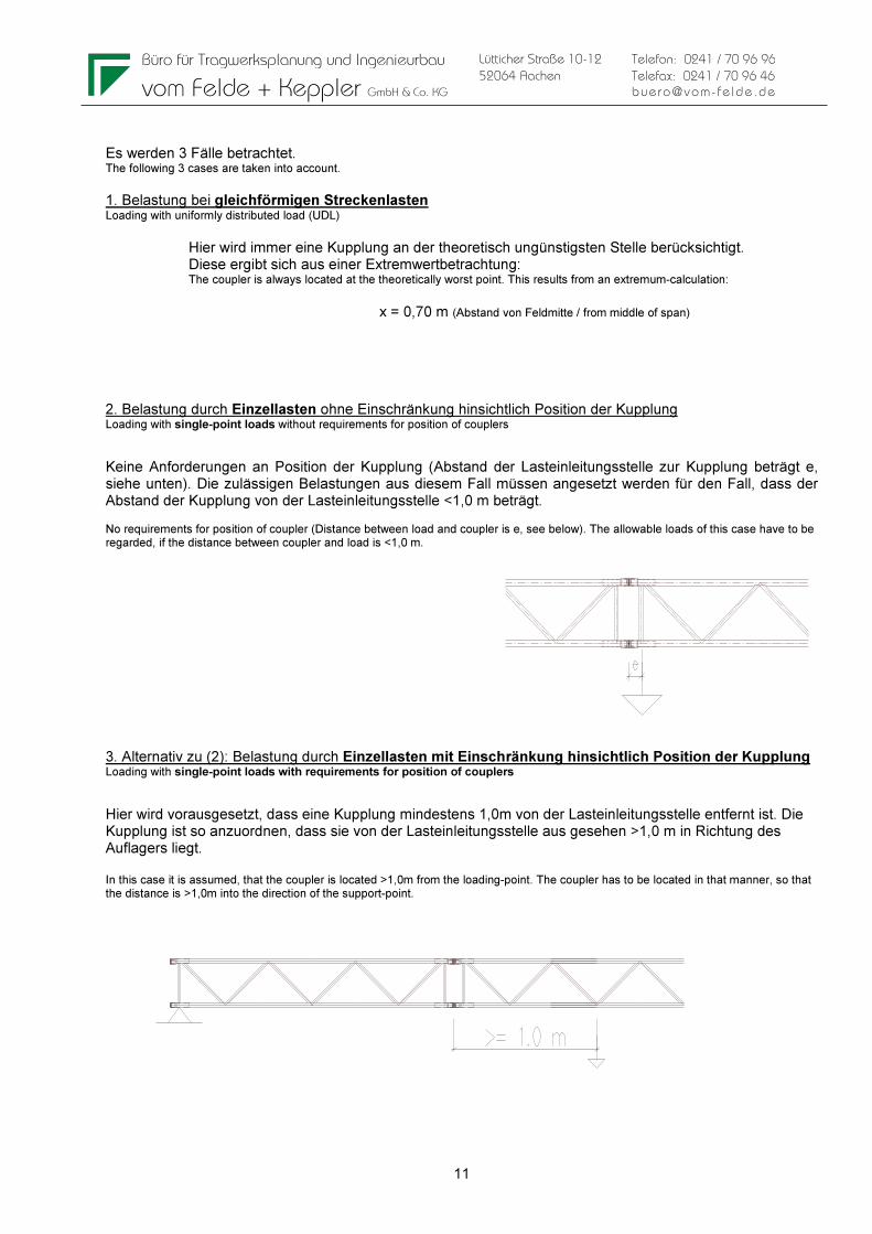
Es werden 3 Fälle betrachtet. The following 3 cases are taken into account.
1. Belastung bei gleichförmigen Streckenlasten Loading with uniformly distributed load (UDL)
Hier wird immer eine Kupplung an der theoretisch ungünstigsten Stelle berücksichtigt. Diese ergibt sich aus einer Extremwertbetrachtung: The coupler is always located at the theoretically worst point. This results from an extremum-calculation:
x = 0,70 m (Abstand von Feldmitte / from middle of span)
2. Belastung durch Einzellasten ohne Einschränkung hinsichtlich Position der Kupplung Loading with single-point loads without requirements for position of couplers
Keine Anforderungen an Position der Kupplung (Abstand der Lasteinleitungsstelle zur Kupplung beträgt e, siehe unten). Die zulässigen Belastungen aus diesem Fall müssen angesetzt werden für den Fall, dass der Abstand der Kupplung von der Lasteinleitungsstelle <1,0 m beträgt. No requirements for position of coupler (Distance between load and coupler is e, see below). The allowable loads of this case have to be regarded, if the distance between coupler and load is <1,0 m.
3. Alternativ zu (2): Belastung durch Einzellasten mit Einschränkung hinsichtlich Position der Kupplung Loading with single-point loads with requirements for position of couplers
Hier wird vorausgesetzt, dass eine Kupplung mindestens 1,0m von der Lasteinleitungsstelle entfernt ist. Die Kupplung ist so anzuordnen, dass sie von der Lasteinleitungsstelle aus gesehen >1,0 m in Richtung des Auflagers liegt. In this case it is assumed, that the coupler is located >1,0m from the loading-point. The coupler has to be located in that manner, so that the distance is >1,0m into the direction of the support-point.
Büro für Tragwerksplanung und Ingenieurbau
vom Felde + Keppler GmbH & Co. KG
12
Lütticher Straße 10-12
52064 Aachen
Telefon: 0241 / 70 96 96
Telefax: 0241 / 70 96 46
buero@vom- fe lde.de
q
l
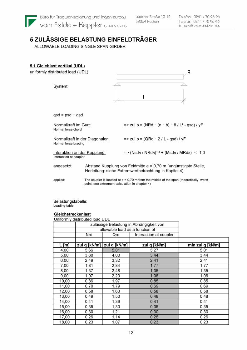
5 ZULÄSSIGE BELASTUNG EINFELDTRÄGER ALLOWABLE LOADING SINGLE SPAN GIRDER
5.1 Gleichlast vertikal (UDL)
uniformly distributed load (UDL) System: qsd = psd + gsd Normalkraft im Gurt: => zul p = (NRd ⋅ (n ⋅ b) ⋅ 8 / L² - gsd) / yF Normal force chord
Normalkraft in der Diagonalen => zul p = (QRd ⋅ 2 / L - gsd) / yF Normal force bracing
Interaktion an der Kupplung: => (NsdG / NRdG)1,3 + (MsdG / MRdG) < 1,0 Interaction at coupler angesetzt: Abstand Kupplung von Feldmitte e = 0,70 m (ungünstigste Stelle, Herleitung: siehe Extremwertbetrachtung in Kapitel 4) applied: The coupler is located at e = 0,70 m from the middle of the span (theoretically worst point, see extremum-calculation in chapter 4)
Belastungstabelle: Loading-table:
Gleichstreckenlast
Uniformly distributed load UDL
Nrd Qrd Interaction at coupler
L [m] zul q [kN/m] zul q [kN/m] zul q [kN/m] min zul q [kN/m]
4,00 5,66 5,01 5,27 5,01
5,00 3,60 4,00 3,44 3,44
6,00 2,49 3,32 2,41 2,41
7,00 1,81 2,84 1,77 1,77
8,00 1,37 2,48 1,35 1,35
9,00 1,07 2,20 1,06 1,06
10,00 0,86 1,97 0,85 0,85
11,00 0,70 1,79 0,69 0,69
12,00 0,58 1,63 0,58 0,58
13,00 0,49 1,50 0,48 0,48
14,00 0,41 1,39 0,41 0,41
15,00 0,35 1,30 0,35 0,35
16,00 0,30 1,21 0,30 0,30
17,00 0,26 1,14 0,26 0,26
18,00 0,23 1,07 0,23 0,23
zulässige Belastung in Abhängigkeit von
allowable load as a function of
Büro für Tragwerksplanung und Ingenieurbau
vom Felde + Keppler GmbH & Co. KG
13
Lütticher Straße 10-12
52064 Aachen
Telefon: 0241 / 70 96 96
Telefax: 0241 / 70 96 46
buero@vom- fe lde.de
P
l/2 l/2
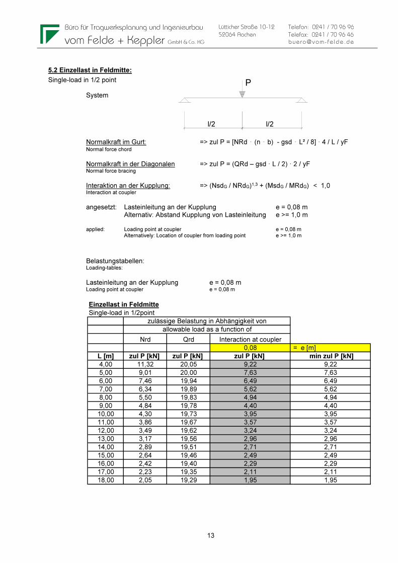
5.2 Einzellast in Feldmitte:
Single-load in 1/2 point System Normalkraft im Gurt: => zul P = [NRd ⋅ (n ⋅ b) - gsd ⋅ L² / 8] · 4 / L / yF Normal force chord
Normalkraft in der Diagonalen => zul P = (QRd – gsd · L / 2) · 2 / yF Normal force bracing Interaktion an der Kupplung: => (NsdG / NRdG)1,3 + (MsdG / MRdG) < 1,0 Interaction at coupler
angesetzt: Lasteinleitung an der Kupplung e = 0,08 m Alternativ: Abstand Kupplung von Lasteinleitung e >= 1,0 m applied: Loading point at coupler e = 0,08 m Alternatively: Location of coupler from loading point e >= 1,0 m
Belastungstabellen: Loading-tables: Lasteinleitung an der Kupplung e = 0,08 m Loading point at coupler e = 0,08 m
Einzellast in Feldmitte
Single-load in 1/2point
Nrd Qrd Interaction at coupler
0,08 = e [m]
L [m] zul P [kN] zul P [kN] zul P [kN] min zul P [kN]
4,00 11,32 20,05 9,22 9,22
5,00 9,01 20,00 7,63 7,63
6,00 7,46 19,94 6,49 6,49
7,00 6,34 19,89 5,62 5,62
8,00 5,50 19,83 4,94 4,94
9,00 4,84 19,78 4,40 4,40
10,00 4,30 19,73 3,95 3,95
11,00 3,86 19,67 3,57 3,57
12,00 3,49 19,62 3,24 3,24
13,00 3,17 19,56 2,96 2,96
14,00 2,89 19,51 2,71 2,71
15,00 2,64 19,46 2,49 2,49
16,00 2,42 19,40 2,29 2,29
17,00 2,23 19,35 2,11 2,11
18,00 2,05 19,29 1,95 1,95
zulässige Belastung in Abhängigkeit von
allowable load as a function of
Büro für Tragwerksplanung und Ingenieurbau
vom Felde + Keppler GmbH & Co. KG
14
Lütticher Straße 10-12
52064 Aachen
Telefon: 0241 / 70 96 96
Telefax: 0241 / 70 96 46
buero@vom- fe lde.de
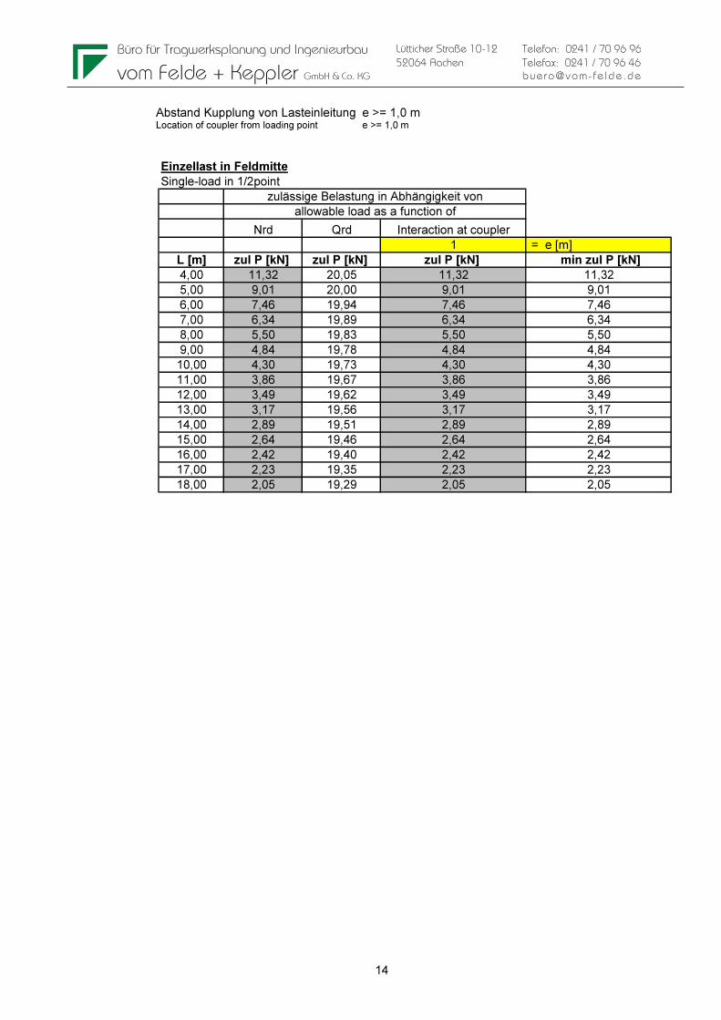
Abstand Kupplung von Lasteinleitung e >= 1,0 m Location of coupler from loading point e >= 1,0 m
Einzellast in Feldmitte
Single-load in 1/2point
Nrd Qrd Interaction at coupler
1 = e [m]
L [m] zul P [kN] zul P [kN] zul P [kN] min zul P [kN]
4,00 11,32 20,05 11,32 11,32
5,00 9,01 20,00 9,01 9,01
6,00 7,46 19,94 7,46 7,46
7,00 6,34 19,89 6,34 6,34
8,00 5,50 19,83 5,50 5,50
9,00 4,84 19,78 4,84 4,84
10,00 4,30 19,73 4,30 4,30
11,00 3,86 19,67 3,86 3,86
12,00 3,49 19,62 3,49 3,49
13,00 3,17 19,56 3,17 3,17
14,00 2,89 19,51 2,89 2,89
15,00 2,64 19,46 2,64 2,64
16,00 2,42 19,40 2,42 2,42
17,00 2,23 19,35 2,23 2,23
18,00 2,05 19,29 2,05 2,05
zulässige Belastung in Abhängigkeit von
allowable load as a function of
Büro für Tragwerksplanung und Ingenieurbau
vom Felde + Keppler GmbH & Co. KG
15
Lütticher Straße 10-12
52064 Aachen
Telefon: 0241 / 70 96 96
Telefax: 0241 / 70 96 46
buero@vom- fe lde.de
P P
l/3l/3 l/3
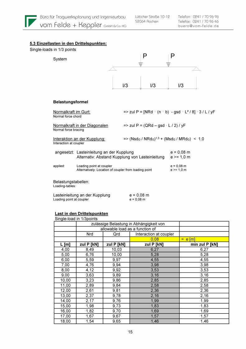
5.3 Einzellasten in den Drittelspunkten:
Single-loads in 1/3 points System Belastungsformel Normalkraft im Gurt: => zul P = [NRd ⋅ (n ⋅ b) - gsd ⋅ L² / 8] · 3 / L / yF Normal force chord
Normalkraft in der Diagonalen => zul P = (QRd – gsd · L / 2) / yF Normal force bracing Interaktion an der Kupplung: => (NsdG / NRdG)1,3 + (MsdG / MRdG) < 1,0
Interaction at coupler angesetzt: Lasteinleitung an der Kupplung e = 0,08 m Alternativ: Abstand Kupplung von Lasteinleitung e >= 1,0 m applied: Loading point at coupler e = 0,08 m Alternatively: Location of coupler from loading point e >= 1,0 m
Belastungstabellen: Loading-tables:
Lasteinleitung an der Kupplung e = 0,08 m Loading point at coupler e = 0,08 m
Last in den Drittelspunkten
Single-load in 1/3points
Nrd Qrd Interaction at coupler
0,08 = e [m]
L [m] zul P [kN] zul P [kN] zul P [kN] min zul P [kN]
4,00 8,49 10,03 6,27 6,27
5,00 6,76 10,00 5,28 5,28
6,00 5,59 9,97 4,55 4,55
7,00 4,76 9,94 3,98 3,98
8,00 4,12 9,92 3,53 3,53
9,00 3,63 9,89 3,16 3,16
10,00 3,23 9,86 2,85 2,85
11,00 2,89 9,84 2,58 2,58
12,00 2,61 9,81 2,36 2,36
13,00 2,37 9,78 2,16 2,16
14,00 2,17 9,76 1,99 1,99
15,00 1,98 9,73 1,83 1,83
16,00 1,82 9,70 1,69 1,69
17,00 1,67 9,67 1,57 1,57
18,00 1,54 9,65 1,46 1,46
zulässige Belastung in Abhängigkeit von
allowable load as a function of
Büro für Tragwerksplanung und Ingenieurbau
vom Felde + Keppler GmbH & Co. KG
16
Lütticher Straße 10-12
52064 Aachen
Telefon: 0241 / 70 96 96
Telefax: 0241 / 70 96 46
buero@vom- fe lde.de
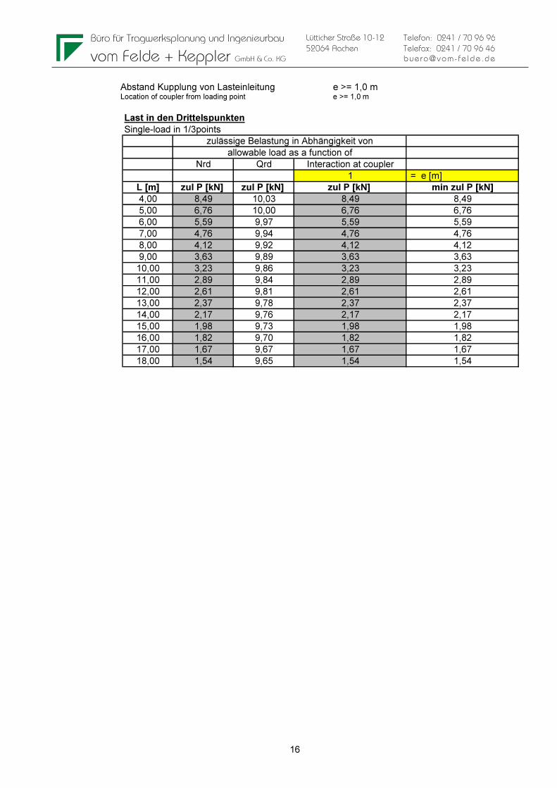
Abstand Kupplung von Lasteinleitung e >= 1,0 m Location of coupler from loading point e >= 1,0 m
Last in den Drittelspunkten
Single-load in 1/3points
Nrd Qrd Interaction at coupler
1 = e [m]
L [m] zul P [kN] zul P [kN] zul P [kN] min zul P [kN]
4,00 8,49 10,03 8,49 8,49
5,00 6,76 10,00 6,76 6,76
6,00 5,59 9,97 5,59 5,59
7,00 4,76 9,94 4,76 4,76
8,00 4,12 9,92 4,12 4,12
9,00 3,63 9,89 3,63 3,63
10,00 3,23 9,86 3,23 3,23
11,00 2,89 9,84 2,89 2,89
12,00 2,61 9,81 2,61 2,61
13,00 2,37 9,78 2,37 2,37
14,00 2,17 9,76 2,17 2,17
15,00 1,98 9,73 1,98 1,98
16,00 1,82 9,70 1,82 1,82
17,00 1,67 9,67 1,67 1,67
18,00 1,54 9,65 1,54 1,54
zulässige Belastung in Abhängigkeit von
allowable load as a function of
Büro für Tragwerksplanung und Ingenieurbau
vom Felde + Keppler GmbH & Co. KG
17
Lütticher Straße 10-12
52064 Aachen
Telefon: 0241 / 70 96 96
Telefax: 0241 / 70 96 46
buero@vom- fe lde.de
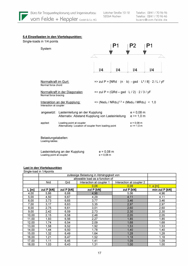
5.4 Einzellasten in den Viertelspunkten:
Single-loads in 1/4 points System Normalkraft im Gurt: => zul P = [NRd ⋅ (n ⋅ b) - gsd ⋅ L² / 8] · 2 / L / yF Normal force chord
Normalkraft in der Diagonalen => zul P = (QRd – gsd · L / 2) · 2 / 3 / yF Normal force bracing Interaktion an der Kupplung: => (NsdG / NRdG)1,3 + (MsdG / MRdG) < 1,0 Interaction at coupler angesetzt: Lasteinleitung an der Kupplung e = 0,08 m Alternativ: Abstand Kupplung von Lasteinleitung e >= 1,0 m applied: Loading point at coupler e = 0,08 m Alternatively: Location of coupler from loading point e >= 1,0 m
Belastungstabellen: Loading-tables:
Lasteinleitung an der Kupplung e = 0,08 m Loading point at coupler e = 0,08 m
Last in den Viertelspunkten
Single-load in 1/4points
Nrd Qrd Interaction at coupler 1 Interaction at coupler 2
0,08 0,08 = e [m]
L [m] zul P [kN] zul P [kN] zul P [kN] zul P [kN] min zul P [kN]
4,00 5,66 6,68 4,96 5,06 4,96
5,00 4,50 6,67 4,29 4,11 4,11
6,00 3,73 6,65 3,77 3,46 3,46
7,00 3,17 6,63 3,35 2,97 2,97
8,00 2,75 6,61 3,01 2,60 2,60
9,00 2,42 6,59 2,73 2,30 2,30
10,00 2,15 6,58 2,48 2,05 2,05
11,00 1,93 6,56 2,27 1,85 1,85
12,00 1,74 6,54 2,09 1,68 1,68
13,00 1,58 6,52 1,92 1,53 1,53
14,00 1,44 6,50 1,78 1,40 1,40
15,00 1,32 6,49 1,64 1,28 1,28
16,00 1,21 6,47 1,52 1,18 1,18
17,00 1,11 6,45 1,41 1,09 1,09
18,00 1,03 6,43 1,31 1,00 1,00
zulässige Belastung in Abhängigkeit von
allowable load as a function of
PPPPPP1 PPPPPP1PPPPPP2
l/4 l/4 l/4 l/4

Büro für Tragwerksplanung und Ingenieurbau
vom Felde + Keppler GmbH & Co. KG
18
Lütticher Straße 10-12
52064 Aachen
Telefon: 0241 / 70 96 96
Telefax: 0241 / 70 96 46
buero@vom- fe lde.de
Abstand Kupplung von Lasteinleitung e >= 1,0 m Location of coupler from loading point e >= 1,0 m
Last in den Viertelspunkten
Single-load in 1/4points
Nrd Qrd Interaction at coupler 1 Interaction at coupler 2
1 1 = e [m]
L [m] zul P [kN] zul P [kN] zul P [kN] zul P [kN] min zul P [kN]
4,00 5,66 6,68 10,75 6,38 5,66
5,00 4,50 6,67 8,89 4,95 4,50
6,00 3,73 6,65 7,21 4,04 3,73
7,00 3,17 6,63 5,97 3,39 3,17
8,00 2,75 6,61 5,05 2,92 2,75
9,00 2,42 6,59 4,35 2,55 2,42
10,00 2,15 6,58 3,79 2,25 2,15
11,00 1,93 6,56 3,35 2,01 1,93
12,00 1,74 6,54 2,98 1,81 1,74
13,00 1,58 6,52 2,67 1,64 1,58
14,00 1,44 6,50 2,41 1,49 1,44
15,00 1,32 6,49 2,19 1,36 1,32
16,00 1,21 6,47 1,99 1,25 1,21
17,00 1,11 6,45 1,82 1,15 1,11
18,00 1,03 6,43 1,66 1,05 1,03
zulässige Belastung in Abhängigkeit von
allowable load as a function of
Büro für Tragwerksplanung und Ingenieurbau
vom Felde + Keppler GmbH & Co. KG
19
Lütticher Straße 10-12
52064 Aachen
Telefon: 0241 / 70 96 96
Telefax: 0241 / 70 96 46
buero@vom- fe lde.de
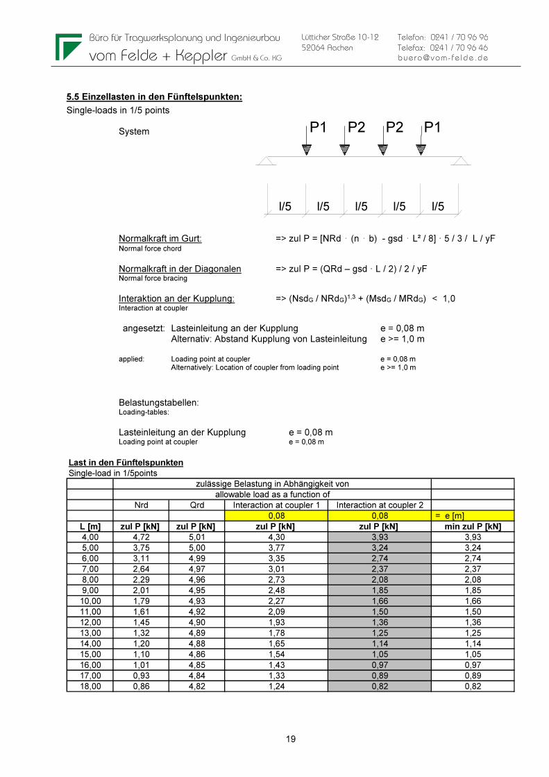
5.5 Einzellasten in den Fünftelspunkten:
Single-loads in 1/5 points System Normalkraft im Gurt: => zul P = [NRd ⋅ (n ⋅ b) - gsd ⋅ L² / 8] · 5 / 3 / L / yF Normal force chord
Normalkraft in der Diagonalen => zul P = (QRd – gsd · L / 2) / 2 / yF Normal force bracing Interaktion an der Kupplung: => (NsdG / NRdG)1,3 + (MsdG / MRdG) < 1,0 Interaction at coupler angesetzt: Lasteinleitung an der Kupplung e = 0,08 m Alternativ: Abstand Kupplung von Lasteinleitung e >= 1,0 m applied: Loading point at coupler e = 0,08 m Alternatively: Location of coupler from loading point e >= 1,0 m
Belastungstabellen: Loading-tables:
Lasteinleitung an der Kupplung e = 0,08 m Loading point at coupler e = 0,08 m
Last in den Fünftelspunkten
Single-load in 1/5points
Nrd Qrd Interaction at coupler 1 Interaction at coupler 2
0,08 0,08 = e [m]
L [m] zul P [kN] zul P [kN] zul P [kN] zul P [kN] min zul P [kN]
4,00 4,72 5,01 4,30 3,93 3,93
5,00 3,75 5,00 3,77 3,24 3,24
6,00 3,11 4,99 3,35 2,74 2,74
7,00 2,64 4,97 3,01 2,37 2,37
8,00 2,29 4,96 2,73 2,08 2,08
9,00 2,01 4,95 2,48 1,85 1,85
10,00 1,79 4,93 2,27 1,66 1,66
11,00 1,61 4,92 2,09 1,50 1,50
12,00 1,45 4,90 1,93 1,36 1,36
13,00 1,32 4,89 1,78 1,25 1,25
14,00 1,20 4,88 1,65 1,14 1,14
15,00 1,10 4,86 1,54 1,05 1,05
16,00 1,01 4,85 1,43 0,97 0,97
17,00 0,93 4,84 1,33 0,89 0,89
18,00 0,86 4,82 1,24 0,82 0,82
allowable load as a function of
zulässige Belastung in Abhängigkeit von
l/5
P1 P2 P2 P1
l/5 l/5 l/5 l/5
Büro für Tragwerksplanung und Ingenieurbau
vom Felde + Keppler GmbH & Co. KG
20
Lütticher Straße 10-12
52064 Aachen
Telefon: 0241 / 70 96 96
Telefax: 0241 / 70 96 46
buero@vom- fe lde.de
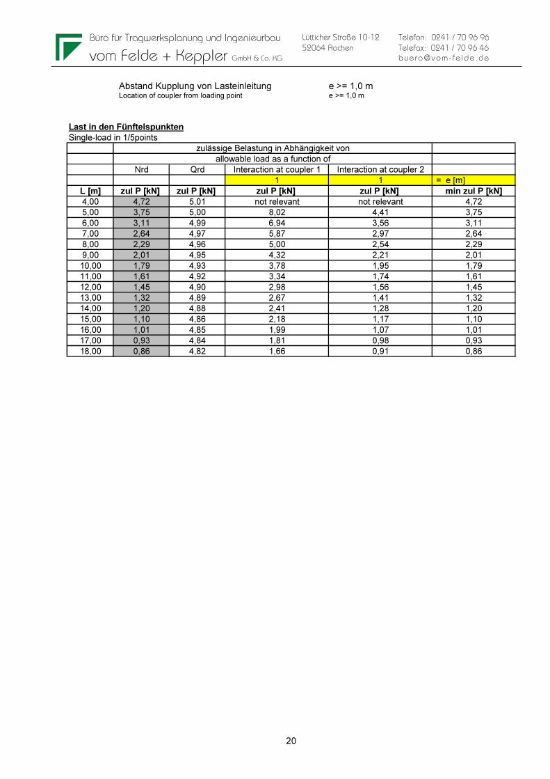
Abstand Kupplung von Lasteinleitung e >= 1,0 m Location of coupler from loading point e >= 1,0 m
Last in den Fünftelspunkten
Single-load in 1/5points
Nrd Qrd Interaction at coupler 1 Interaction at coupler 2
1 1 = e [m]
L [m] zul P [kN] zul P [kN] zul P [kN] zul P [kN] min zul P [kN]
4,00 4,72 5,01 not relevant not relevant 4,72
5,00 3,75 5,00 8,02 4,41 3,75
6,00 3,11 4,99 6,94 3,56 3,11
7,00 2,64 4,97 5,87 2,97 2,64
8,00 2,29 4,96 5,00 2,54 2,29
9,00 2,01 4,95 4,32 2,21 2,01
10,00 1,79 4,93 3,78 1,95 1,79
11,00 1,61 4,92 3,34 1,74 1,61
12,00 1,45 4,90 2,98 1,56 1,45
13,00 1,32 4,89 2,67 1,41 1,32
14,00 1,20 4,88 2,41 1,28 1,20
15,00 1,10 4,86 2,18 1,17 1,10
16,00 1,01 4,85 1,99 1,07 1,01
17,00 0,93 4,84 1,81 0,98 0,93
18,00 0,86 4,82 1,66 0,91 0,86
allowable load as a function of
zulässige Belastung in Abhängigkeit von
Büro für Tragwerksplanung und Ingenieurbau
vom Felde + Keppler GmbH & Co. KG
21
Lütticher Straße 10-12
52064 Aachen
Telefon: 0241 / 70 96 96
Telefax: 0241 / 70 96 46
buero@vom- fe lde.de
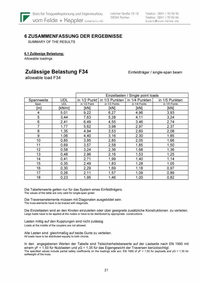
6 ZUSAMMENFASSUNG DER ERGEBNISSE SUMMARY OF THE RESULTS
6.1 Zulässige Belastung:
Allowable loadings
Zulässige Belastung F34 Einfeldträger / single-span beam
allowable load F34
Spannweite UDL in 1/2 Punkt in 1/3 Punkten in 1/4 Punkten in 1/5 PunktenSpan UDL in 1/2 Point in 1/3 Points in 1/4 Points in 1/5 Points
[m] [kN/m] [kN] [kN] [kN] [kN]
4 5,01 9,22 6,27 4,96 3,93
5 3,44 7,63 5,28 4,11 3,24
6 2,41 6,49 4,55 3,46 2,74
7 1,77 5,62 3,98 2,97 2,37
8 1,35 4,94 3,53 2,60 2,08
9 1,06 4,40 3,16 2,30 1,85
10 0,85 3,95 2,85 2,05 1,66
11 0,69 3,57 2,58 1,85 1,50
12 0,58 3,24 2,36 1,68 1,36
13 0,48 2,96 2,16 1,53 1,25
14 0,41 2,71 1,99 1,40 1,14
15 0,35 2,49 1,83 1,28 1,05
16 0,30 2,29 1,69 1,18 0,97
17 0,26 2,11 1,57 1,09 0,89
18 0,23 1,95 1,46 1,00 0,82
Einzellasten / Single point loads
Die Tabellenwerte gelten nur für das System eines Einfeldträgers. The values of the table are only valid for single-span girder.
Die Traversenelemente müssen mit Diagonalen ausgebildet sein. The truss-elements have to be braced with diagonals.
Die Einzellasten sind an den Knoten einzuleiten oder über geeignete zusätzliche Konstruktionen zu verteilen. Large loads have to be applied at the nodes or have to be distributed by appropriate constructions.
Lasten mittig auf den Kupplungen sind nicht zulässig. Loads at the middle of the couplers are not allowed. Alle Lasten sind gleichmäßig auf beide Gurte zu verteilen. All loads have to be distributed equally to both chords.
In den angegebenen Werten der Tabelle sind Teilsicherheitsbeiwerte auf der Lastseite nach EN 1990 mit einem yF = 1,50 für Nutzlasten und yG = 1,35 für das Eigengewicht der Traversen berücksichtigt. The specified values include partial safety coefficients on the loadings side acc. EN 1990 of yF = 1.50 for payloads and yG = 1.35 for selfweight of the truss.
Büro für Tragwerksplanung und Ingenieurbau
vom Felde + Keppler GmbH & Co. KG
22
Lütticher Straße 10-12
52064 Aachen
Telefon: 0241 / 70 96 96
Telefax: 0241 / 70 96 46
buero@vom- fe lde.de
Bei Anwendungsfällen, die auf Grundlage anderer Normen berechnet werden, können die Teilsicherheitsbeiwerte auf der Lastseite angepasst werden (z.B. fliegende Bauten nach EN 13814, yF = 1,35 für Nutzlasten). For applictaions which can be calculated on the basis of other codes, the partial safety factors can be adjusted (for example temporary structures acc. EN 13814, yF = 1.35 for payloads).
Bei Anwendung des British Standard (BS) und des ANSI müssen die in den Tabellen aufgeführten zulässigen Belastungen mit dem Faktor 0,85 multipliziert werden. To use the resulting allowable loads with British Standard (BS) and ANSI, allowable loads listed in tables have to be multiplied by 0.85.
Die Tabellenwerte sind berechnet ohne Anforderung an die Position der Kupplung. Für den Fall, dass der Abstand der Kupplungen von den Lasteinleitungspunkten von Einzellasten > 1,0m in Richtung des Auflagers beträgt, können die Werte aus den Berechnungen der verschiedenen Lastsituationen (siehe Kapitel 5) verwendet werden. The values are calculated with no requirements for the location o the couplers. In case that the distance from the couplers to the loadingpoints of the single-point loads is > 1,0 m into the direction of the support, the values of the calculations for the different loadcases can be used (see chapter 5).
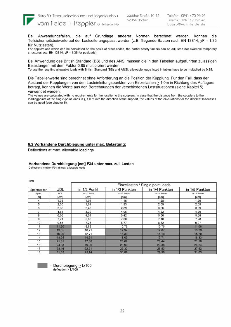
6.2 Vorhandene Durchbiegung unter max. Belastung:
Deflections at max. allowable loadings Vorhandene Durchbiegung [cm] F34 unter max. zul. Lasten Deflections [cm] for F34 at max. allowable loads
[cm]
Spannweiten UDL in 1/2 Punkt in 1/3 Punkten in 1/4 Punkten in 1/5 PunktenSpan UDL in 1/2 Point in 1/3 Points in 1/4 Points in 1/5 Points
[m] [cm] [cm] [cm] [cm] [cm]
4 1,36 1,01 1,16 1,28 1,29
5 2,30 1,64 1,93 2,09 2,09
6 3,36 2,43 2,89 3,06 3,09
7 4,61 3,39 4,06 4,22 4,29
8 6,06 4,51 5,42 5,56 5,68
9 7,71 5,80 7,00 7,10 7,28
10 9,55 7,26 8,77 8,82 9,07
11 11,60 8,89 10,76 10,75 11,08
12 13,85 10,71 12,97 12,87 13,29
13 16,29 12,71 15,39 15,19 15,70
14 18,95 14,91 18,03 17,71 18,33
15 21,81 17,30 20,89 20,44 21,18
16 24,88 19,90 23,99 23,38 24,24
17 28,16 22,71 27,32 26,53 27,52
18 31,65 25,74 30,89 29,90 31,03
Einzellasten / Single point loads
= Durchbiegung > L/100 deflection > L/100