Embed Size (px)
Citation preview
30 807 01 a ,.$ WERKE
,.$® Calorimeter System C 7000with Cooler C 7002
23(5$7,1*�,16758&7,216 (1�86$
Reg.-No. 4343-01Vers. 07 09.07

IKA-WERKE C 7000 Ver. 07 09.07
&(�±�.21)250,7b76(5./b581* '(Wir erklären in alleiniger Verantwortung, dass dieses Produkt den Bestimmungender Richtlinien 89 / 336 / EG und 2006 / 95 / EG entspricht und mit folgenden Nor-men und normativen Dokumenten übereinstimmt: DIN EN IEC 61 010-1 und DIN ENIEC 61 326-1.
&(�±�'(&/$5$7,21�2)�&21),50,7< (1We declare under our sole responsibility that this product corresponds to the regula-tions 89 / 336 / EEC and 2006 / 95 / EEC and conforms with the standards or stan-dardized documents: DIN EN IEC 61 010-1 and DIN EN IEC 61 326-1.
'e&/$5$7,21�'(�&21)250,7e�&( )5Nous déclarons sous notre responsabilité que se prodiut est conforme aux régle-mentations 89 / 336 / CEE et 2006 / 95 / CEE et en conformité avec les normes oudocuments normalisés suivant: DIN EN IEC 61 010-1 et DIN EN IEC 61 326-1.
'(&/$5$&,21�'(�&21)250,'$'�'(�&( (6Declaramos por nuestra responsabilidad propia que este producto corresponde alas directrices 89 / 336 / CEE y 2006 / 95 / CEE y que cumple las normas o docu-mentos normativos siguientes: DIN EN IEC 61 010-1 y DIN EN IEC 61 326-1.
&(�±�',&+,$5$=,21(�',�&21)250,7¬ ,7Dichiariamo, assumendone la piena responsabilità, che il prodotto è conforme alleseguenti direttive 89 / 336 / CCE e 2006 / 95 / CCE, in accordo ai seguenti regola-menti e documenti: DIN EN IEC 61 010-1 e DIN EN IEC 61 326-1.
IKA-WERKE C 7000 Ver. 07 09.07
([SODQDWLRQ�RI�V\PEROV
This symbol identifies information WKDW�LV�RI�DEVROXWH�LPSRUWDQFH�WR�HQVXUH�\RXUKHDOWK�DQG�VDIHW\� Failure to observe this information may be detrimental to yourhealth or may result in injuries.
This symbol identifies information WKDW�LV�RI�LPSRUWDQW�WR�HQVXUH�SUREOHP�IUHHWHFKQLFDO�RSHUDWLRQ�RI�WKH�GHYLFH� Failure to observe this information may result indamage to the calorimeter system.
This symbol identifies information that is important to ensure problem-free operationof calorimetric measurements and for working with the calorimeter system. Failure toobserve this information may result in inaccurate measurement results.
+
IKA-WERKE C 7000 Ver. 07 09.07
3DJH�,��
&RQWHQWV
3DJH� )RU�\RXU�VDIHW\ ������������������������������������������������������������������������������� ���� 8VHU�QRWHV �������������������������������������������������������������������������������������� ���2.1 Notes on using the operating instructions......................................... 2-1
2.2 Warranty ......................................................................................... 2-1
2.3 Warranty and Liability...................................................................... 2-2
2.4 System Features ............................................................................. 2-3
� 7UDQVSRUW��6WRUDJH��,QVWDOODWLRQ�/RFDWLRQ �������������������������������������� ���3.1 Transport and Storage Conditions.................................................... 3-1
3.2 Installation Location ........................................................................ 3-1
3.3 Unpacking....................................................................................... 3-2
3.4 Delivery Scope ............................................................................... 3-2
� 'HVFULSWLRQ�RI�6\VWHP�&RPSRQHQWV ���������������������������������������������� ���4.1 Calorimeter C 7000 ......................................................................... 4-1
4.2 Cooler C 7002................................................................................. 4-2
� 3ULQFLSOHV�RI�&DORULPHWULF�0HDVXUHPHQW���������������������������������������� ���5.1 Determining the Gross Calorific Value.............................................. 5-1
5.2 Corrections ..................................................................................... 5-4
5.3 Complete Combustion ..................................................................... 5-5
5.4 Calibration ...................................................................................... 5-6
� &RPPLVVLRQLQJ ������������������������������������������������������������������������������ ���6.1 Connecting the mains lead .............................................................. 6-1
6.2 Connecting peripherals.................................................................... 6-1
6.3 Switching the system on .................................................................. 6-2
6.4 Display and control elements ........................................................... 6-2
6.5 Menu structure ................................................................................ 6-4
6.6 Configuration of the C 7000 Calorimeter .......................................... 6-6
6.7 Examples of entries......................................................................... 6-8
6.8 Switching off ................................................................................. 6-11
&RQWHQWV
IKA-WERKE C 7000 Ver. 07 09.07
3DJH�,��
� 3UHSDUDWLRQ�DQG�&DUU\LQJ�2XW�0HDVXUHPHQWV ������������������������������� ���7.1 Recommendations for calibration ..................................................... 7-2
7.2 Notes on samples............................................................................ 7-5
7.3 Preparation for measurement .......................................................... 7-7
7.4 Carrying out a measurement.......................................................... 7-13
7.5 Manual recording of the C value .................................................... 7-14
7.6 Cleaning and checking decomposition vessels ............................... 7-15
� (YDOXDWLRQ�RI�&DORULILF�9DOXH�7HVWV������������������������������������������������ ���8.1 Output and treatment of test data .................................................... 8-1
8.2 Evaluation of tests........................................................................... 8-4
8.3 Test simulation................................................................................ 8-6
� &DUH�DQG�0DLQWHQDQFH�������������������������������������������������������������������� ���9.1 Maintenance ................................................................................... 9-1
9.2 Recommendations for cleaning ........................................................ 9-1
�� 0HVVDJHV�DQG�7URXEOHVKRRWLQJ ��������������������������������������������������� ����10.1 Messages from the C 7000 Calorimeter ......................................... 10-1
10.2 Fault without signal from Calorimeter ............................................. 10-4
10.3 Signals from the C 7002 Cooler ..................................................... 10-4
�� $FFHVVRULHV�DQG�&RQVXPDEOHV���������������������������������������������������� ����11.1 Accessories .................................................................................. 11-1
11.2 Consumables ................................................................................ 11-1
�� 7HFKQLFDO�'DWD������������������������������������������������������������������������������ ����12.1 Technical data for C 7000 Calorimeter ........................................... 12-1
12.2 Technical data for C 7002 Cooler................................................... 12-1
�� ,QGH[��������������������������������������������������������������������������������������������� ����
IKA-WERKE C 7000 Ver. 07 09.07
3DJH����
�� )RU�\RXU�VDIHW\In order to be able to use the appliance properly and safely, every user must firstread the operating instructions and observe the safety instructions containedtherein. Take care of these operating instructions and keep them in a place wherethey can be accessed by everyone.
The C 7000 calorimeter system may only be used to determine the gross calorificvalue of solid and liquid materials in accordance with DIN 51900 and ISO 1928. Forthis purpose, use only original IKA decomposition vessels C 7010 and C 7012. Forfurther details please see the operating instructions of the decomposition vesselsC 7010 and C 7012.
The maximum amount of energy input into the decomposition vessel must not ex-ceed ������- (select the weight of the sample accordingly). The permissible oper-ating pressure of ����EDU ����0SD� must not be exceeded. The maximum permissi-ble operating temperature must not exceed ����&.Do not fill the decomposition vessel too full of the sample. Only fill the decomposi-tion vessel with oxygen up to a maximum pressure of ���EDU ���0SD�. Monitor theadjusted pressure on the pressure reducer. Perform a check before every combus-tion to ensure there are no leaks combustion (please observe the operating instruc-tions of the decomposition vessels C 7010 and C 7012, chapter ”Leakage test”).
Many substances tend to combust in an explosive manner (for example because ofthe formation of peroxide). This may cause the decomposition vessel to burst.7KH�VWDQGDUG�GHFRPSRVLWLRQ�YHVVHOV�PXVW�QRW� EH� XVHG� IRU� H[DPLQDWLRQV�RQVDPSOHV�WKDW�DUH�FDSDEOH�RI�H[SORGLQJ��,W�LV�DEVROXWHO\�HVVHQWLDO�WR�XVH�D�VSH�FLDO�KLJK�SUHVVXUH�GHFRPSRVLWLRQ�YHVVHO�WR�FRQWDLQ�WKH�VDPSOH�LQ�WKHVH�FDVHV�7KLV� KLJK�SUHVVXUH� GHFRPSRVLWLRQ� YHVVHO� FDQ�RQO\� EH� XVHG�ZLWK� WKH�&� ����FDORULPHWHU�V\VWHP�Substances of which the combustion behavior is not known must be examined fortheir combustion behavior before combustion in the decomposition vessel C 7010 orC 7012 (danger of explosion). If you are burning XQNQRZQ�VDPSOHV, leave the roomor NHHS�D�VDIH�GLVWDQFH�EHWZHHQ you and the calorimeter.Benzoic acid must only be burned in the form of pellets! Combustible dust and pow-der must be compressed into pellets before combustion. Oven-dry dust and powdersuch as wood chips, hay, straw, etc. burn in an explosive manner! They must bemoistened first! Readily combustible liquids with a low vapor pressure must not become in direct contact with the cotton thread (for example tetramethyl dihydrogendisiloxan)!
In addition, toxic residues of combustion are possible in the form of gasses, ash orprecipitates on the inner wall of the decomposition vessel, for example.
2EVHUYH� WKH�DFFLGHQW�SUHYHQWLRQ� UHTXLUHPHQWV�DSSOLFDEOH� WR� WKH�DFWLYLW\DQG�WKH�ZRUN�VWDWLRQ��:HDU�SHUVRQDO�VDIHW\�HTXLSPHQW�
([SORVLYHVXEVWDQFHV
,QWHQGHG�SXU�SRVH
&RPEXVWLRQUHVLGXH�DX[LOLDU\PDWHULDOV
2SHUDWLQJUHTXLUHPHQWV
1RWHV�RQ�WKHVDPSOH
LQWHQGHG�SXU�SRVH
��)RU�\RXU�VDIHW\
IKA-WERKE C 7000 Ver. 07 09.07
3DJH����
When handling combustion samples, combustion residues and auxiliary materials,the appropriate safety requirements must be observed. The following are examplesof substances that may cause dangers:
– corrosive– easily flammable– capable of exploding– contaminated with bacteria– toxic
When working with oxygen, observe the appropriate requirements.Danger warning: As a compressed gas, oxygen promotes combustion, supportscombustion intensively and may react violently with combustible substances.'R�QRW�XVH�DQ\�RLO�RU�JUHDVH�Keep all gas lines and screw connections that carry oxygen free from grease.Observe the accident prevention requirements applicable to the activity and thework station.Close the main valve on the oxygen supply when work is complete.Only carry out maintenance work when the system is depressurised.
When using crucibles made of stainless steel, their condition should be carefullychecked after every experiment.A reduction in the thickness of the material may cause the crucible to burn and maydamage the decomposition vessel. For reasons of safety, crucibles must not beused any more after a maximum of 25 combustion procedures.
The decomposition vessel C 7010 and C 7012 are manufactured in accordance withthe regulation for pressure vessels 97/ 23/ EC. This can be recognized from the &(V\PERO with the identifying number of the testing station named. The decompositionvessel is a pressure device of Category III. The decomposition vessel has beensubjected to an EC prototype test. The CE declaration of conformity represents ourguarantee to you that this decomposition vessel complies with the pressure devicedescribed in the EC prototype test certificate. The decomposition vessel has beensubjected to a pressure test at a test pressure of ����EDU and a leak test with oxy-gen at 30 bar.Decomposition vessels are H[SHULPHQW�DXWRFODYHV and must be tested by a SUR�IHVVLRQDOO\�WUDLQHG�SHUVRQ each time before they are used.An individual application is understood here to mean a series of experiments thatare performed under roughly the same conditions in terms of pressure and tem-perature Experiment autoclaves must be operated in special chambers (C 7000).
The decomposition vessel must be subject to repeated tests (internal tests andpressure tests) by a person with professional training. The intervals between testsmust be determined by the operator based on experience, operating manner andthe material used in the decomposition vessel.7KH�GHFODUDWLRQ�RI�FRQIRUPLW\�ORVHV�LWV�YDOLGLW\�LI�PHFKDQLFDO�PRGLILFDWLRQV�DUHPDGH�WR�WKH�H[SHULPHQW�DXWRFODYHV�RU�LI�VWDELOLW\�FDQ�QR�ORQJHU�EH�JXDUDQWHHGDV�D�UHVXOW�RI�KHDY\�FRUURVLRQ��IRU�H[DPSOH�KROHV�HDWHQ�LQ�LW�E\�KDORJHQV��The WKUHDGLQJ on the body of the decomposition vessel and cap screw in particularare subject to a high level of mechanical stress and must therefore be monitoredregularly for ZHDU�DQG�WHDU.The condition of the seals must be checked for functionality must be ensured bymeans of a test for leaks (please observe the Operating Instructions for the decom-position vessel).Pressure tests and service tasks on the decomposition vessel must only be per-formed by persons with professional training.
2[\JHQ
8VLQJ�D�FUXFLEOHPDGH�RI�VWDLQ�OHVV�VWHHO
6SHFLILFDWLRQ�RIWKH�GHFRPSRVL�WLRQ�YHVVHO
5HSHDWHG�WHVWV
LQWHQGHG�SXU�SRVH
IKA-WERKE C 7000 Ver. 07 09.07
3DJH����
:H�UHFRPPHQG�WKDW�WKH�GHFRPSRVLWLRQ�YHVVHO�EH�VHQW�LQWR�RXU�IDFWRU\�IRU�LQ�VSHFWLRQ�DQG� UHSDLUV� LI� QHFHVVDU\�DIWHU� HLWKHU� ����� H[SHULPHQWV� RU� DIWHU� RQH\HDU�RU��GHSHQGLQJ�RQ�WKH�DSSOLFDWLRQ��HYHQ�VRRQHU�WKDQ�WKLV�A person with professional training as defined in these operating instructions issomeone
1. whose training, knowledge and experience gained through practical activitiesensures that that person will perform the tests in a proper manner.
2. who is sufficiently reliable
3. who is not subject to any instructions in terms of testing activity
4. who is equipped with suitable testing equipment if necessary
5. who can provide suitable proof demonstrating compliance with the requirementslisted in 1.
National regulations and laws for operating pressure containers must be observed!Anyone who operates a pressure container must maintain it in proper condition,must monitor it and perform necessary maintenance and repair tasks without delay,and must take measures appropriate for the circumstances to ensure safety.$�SUHVVXUH�FRQWDLQHU�PXVW�QRW�EH�RSHUDWHG�LI�LW�H[KLELWV�GHIHFWV�WKDW�FRXOG�HQ�GDQJHU�WKRVH�ZRUNLQJ�ZLWK�LW�RU�WKLUG�SDUWLHV� You can obtain a copy of the pres-sure vessel regulation from Carl Heymann Verlag or Beuth Verlag.
'HILQLWLRQ�RISHUVRQ�ZLWKSURIHVVLRQDOWUDLQLQJ
2SHUDWLQJ�SUHV�VXUH�FRQWDLQHUV

IKA-WERKE C 7000 Ver. 07 09.07
IKA-WERKE C 7000 Ver. 07 09.07
3DJH����
�� 8VHU�QRWHV
���� 1RWHV�RQ�XVLQJ�WKH�RSHUDWLQJ�LQVWUXFWLRQVIn this section you will learn how to make the most effective use of these OperatingInstructions so as to be able to work safely with the calorimeter system.
7KH� LQVWUXFWLRQV�JLYHQ� LQ�6HFWLRQ� �� ³)RU� \RXU�6DIHW\´�PXVW�EH� IROORZHGZLWKRXW�IDLO�Work through Sections 1 ... 10 in numerical order.Section 3 "Transport, Storage, Installation Location" is particularly relevant tosystem reliability and ensuring high accuracy of measurements. Section 4 describesthe system components and Section 5 contains the basic principles of calorimetry.
Once you have carried out the procedures described in Section 6 "Commissioning",and Section 7 "Preparing and Carrying Out Measurements" the calorimeter is readyfor use.In Section 8 the evaluation of calorific value measurements and the possibility of testsimulation are explained.Section 9 gives important information on care and maintenance, and Section 10explains the display messages and gives advice on troubleshooting and thecorrection of simple problems.
Information on accessories, consumables, and the technical data for the unit aregiven in Sections 11 and 12. Section 13 contains the index.
The figures c, d, e etc. in the following chapters indicate actions that must alwaysbe carried out in the sequence given.
���� :DUUDQW\In accordance with IKA warranty conditions, the warranty period is 12 months. Forclaims under the warranty please contact your local dealer. You may also send themachine direct to our works, enclosing the delivery invoice and giving reasons forthe claim. You will be liable for freight costs.
The warranty does not cover wearing parts, nor does it apply to faults resulting fromimproper use or insufficient care and maintenance contrary to the instructions in thisoperating manual.
6WXG\LQJ6HFWLRQV���������
&DUU\LQJ�RXWWHVWV
+
��8VHU�1RWHV
IKA-WERKE C 7000 Ver. 07 09.07
3DJH����
���� :DUUDQW\�DQG�/LDELOLW\Please read through these Operating Instructions attentively. IKA only acceptsresponsibility for the safety, reliability and performance of the device if:• the unit has been used in accordance with the operating instructions;• only persons authorised by the manufacturer have carried out maintenance or
repair work on the unit, and• only original parts and original accessories have been used for repairs.
The calorimeter must only be opened by your Technical Service Department.If servicing is required, we recommend that you take advantage of your TechnicalService Department.
Otherwise, please make yourself familiar with the relevant safety and accidentprevention regulations.IKA accepts no liability for damage or costs that arise due to accidents, misuse ofthe unit, or unauthorised changes, repairs or modifications.
3DUWV�FDUU\LQJHOHFWULF�YROWDJH
IKA-WERKE C 7000 Ver. 07 09.07
3DJH����
���� 6\VWHP�)HDWXUHVThe C 7000 calorimeter is used for the routine determination of the gross calorificvalue of solid and liquid substances. The system accessories ensure that it can beindividually adapted to laboratory tasks (see also Section 11).
The system has the following important features:
• patented double-drying measuring procedure;
• short measurement time, ca. 3 minutes for one determination;
• well over a hundred determinations per day and calorimeter are possible;
• automated measurement reduces routine tasks;
• fully-integrated, independent, microprocessor-controlled calorimeter;
• film key panel provides convenient operation and protection against laboratoryconditions;
• integrated fault detection with plain-text display;
• simple, well-proven operation;
• parallel port for direct connection of printer;
• memory for 100 tests;
• automatic acceptance of data from connected balance;
• calculation of calorific value under various conditions;
• four different calculation modes:standard, with and without titration,carbon, with and without titration;
• online data transfer to an external PC;
• automatic recognition of up to 8 decomposition vessels;
• maximum energy input from decomposition vessel: 30.000 J:this corresponds to a temperature increase in the decomposition vesselof about 25 K.

IKA-WERKE C 7000 Ver. 07 09.07
IKA-WERKE C 7000 Ver. 07 09.07
3DJH����
�� 7UDQVSRUW��6WRUDJH��,QVWDOODWLRQ�/RFDWLRQ
���� 7UDQVSRUW�DQG�6WRUDJH�&RQGLWLRQVDuring transport and storage, the system must be protected against mechanicalshock, vibration, dust deposits, and corrosive atmospheres. In addition, the relativehumidity should not exceed 80%.
In case of repair the device has to be cleaned and free from any materials whichmay constitute a health hazard.
If you require servicing, return the appliance in its original packaging. Storagepackaging is not sufficient. Please also use suitable transport packaging.
���� ,QVWDOODWLRQ�/RFDWLRQWhen installing the unit, observe the national and local regulations for the operationof pressure vessels that apply at the site selected.To ensure high accuracy of measurement, a constant ambient temperature is animportant precondition. For this reason, the chosen installation location should fulfilthe following conditions:
• not exposed to direct sunlight;
• no drafts (e.g. not beside a window, door or air-conditioning vent);
• sufficiently far from heating radiators and other heat sources;
• room temperature must be between 18 °C and 30 °C: to ensure good meas-urement quality, there should be no variation in temperature;
• the system must be installed on a horizontal surface;
• If the C 7002 cooler is to be used, a water supply with a supply pressure of lessthan 9 bar is required near the installation location, or a suitable cold water sup-ply (e.g. IKA KV 500).
For operation of the system, a power supply corresponding to the typeplates ofsystem components must be available at the installation location. An oxygen supplywith a pressure gauge, which can supply 99.95% pure oxygen, quality 3.5 at a pres-sure of 30 bar is also required. A shut-off valve for the oxygen supply must be in-stalled. Observe the instructions on handling oxygen given in Section 1 "For yoursafety”.
+
��7UDQVSRUW��6WRUDJH��,QVWDOODWLRQ�/RFDWLRQ
IKA-WERKE C 7000 Ver. 07 09.07
3DJH����
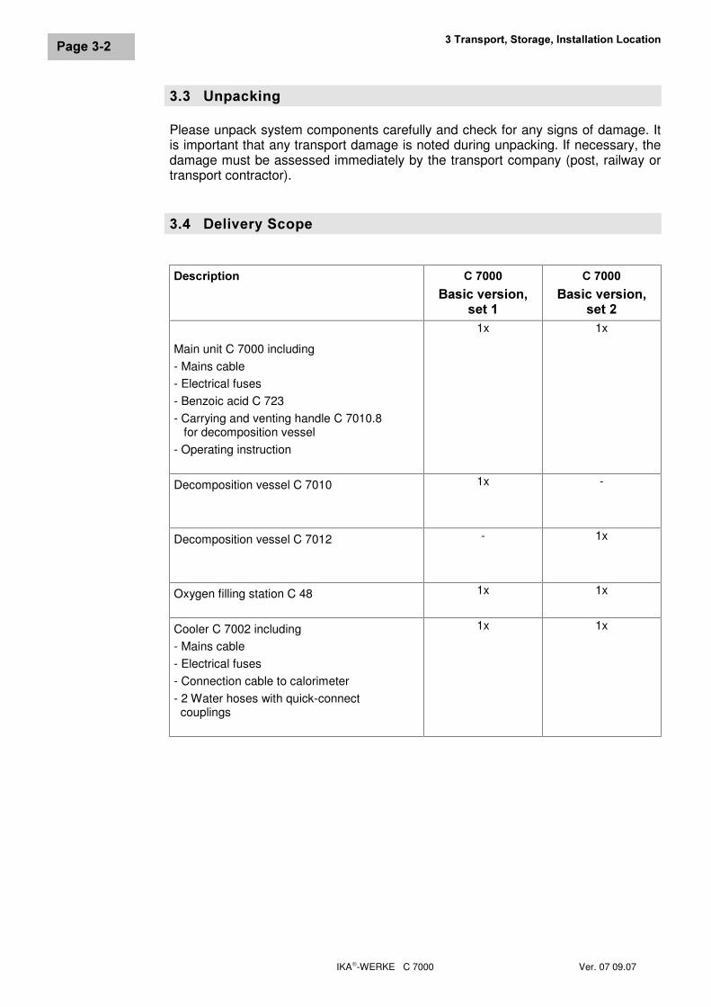
���� 8QSDFNLQJPlease unpack system components carefully and check for any signs of damage. Itis important that any transport damage is noted during unpacking. If necessary, thedamage must be assessed immediately by the transport company (post, railway ortransport contractor).
���� 'HOLYHU\�6FRSH
'HVFULSWLRQ &�����%DVLF�YHUVLRQ�
VHW��
&�����%DVLF�YHUVLRQ�
VHW��
Main unit C 7000 including- Mains cable- Electrical fuses- Benzoic acid C 723- Carrying and venting handle C 7010.8 for decomposition vessel- Operating instruction
1x 1x
Decomposition vessel C 7010 1x -
Decomposition vessel C 7012 - 1x
Oxygen filling station C 48 1x 1x
Cooler C 7002 including- Mains cable- Electrical fuses- Connection cable to calorimeter- 2 Water hoses with quick-connect couplings
1x 1x
IKA-WERKE C 7000 Ver. 07 09.07
3DJH����
�� 'HVFULSWLRQ�RI�6\VWHP�&RPSRQHQWV
���� &DORULPHWHU�&�����
� �� ��� � �
1
�
�
&�����)URQW�YLHZ
�
�
�
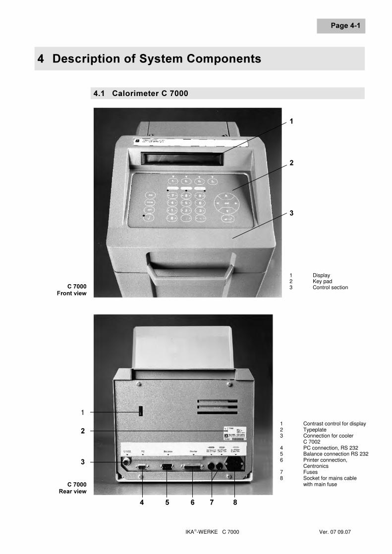
1 Display2 Key pad3 Control section
&�����5HDU�YLHZ
1 Contrast control for display2 Typeplate3 Connection for cooler
C 70024 PC connection, RS 2325 Balance connection RS 2326 Printer connection,
Centronics7 Fuses8 Socket for mains cable
with main fuse
��'HVFULSWLRQ�RI�6\VWHP�&RPSRQHQWV
IKA-WERKE C 7000 Ver. 07 09.07
3DJH����
Commands and test parameters are entered in interactive mode using the key pad,and entries can be seen in the display.
To enter parameters, there is a membrane-type key pad in the removable controlsection of the calorimeter. There is also an illuminated two-line display with 40 char-acters in each line. The display contrast can be individually adjusted using the con-trol on the rear of the unit.During a test, all phases of the measurement process are controlled and monitored,and the display shows the current state of the system and test data.In the measuring cell, calorimetric tests are carried out. They involve burning a sam-ple of combustible material under precisely defined conditions. In the decompositionvessel, there are four temperature sensors, which record its temperature.
���� &RROHU�&�����
&RROHU�&�����)URQW�YLHZ
�
�
�
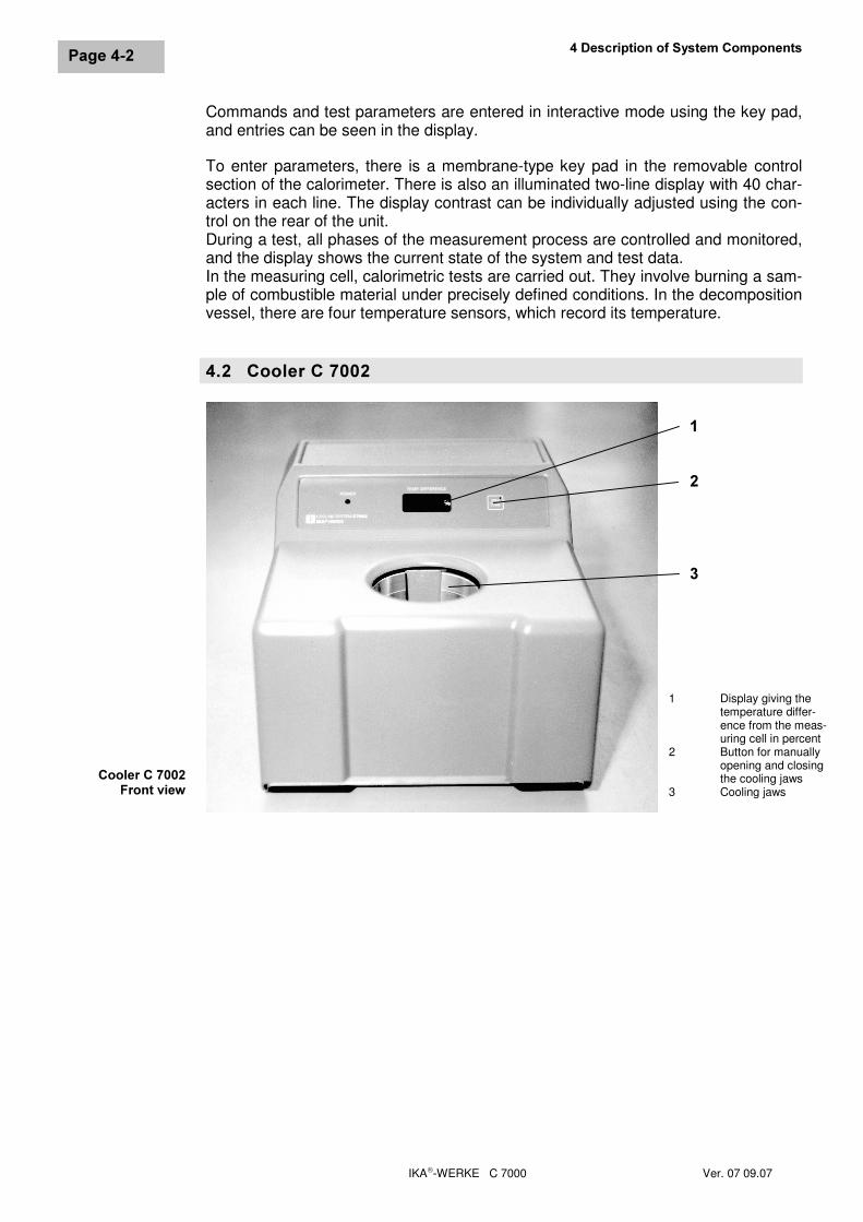
1 Display giving thetemperature differ-ence from the meas-uring cell in percent
2 Button for manuallyopening and closingthe cooling jaws
3 Cooling jaws
IKA-WERKE C 7000 Ver. 07 09.07
3DJH����
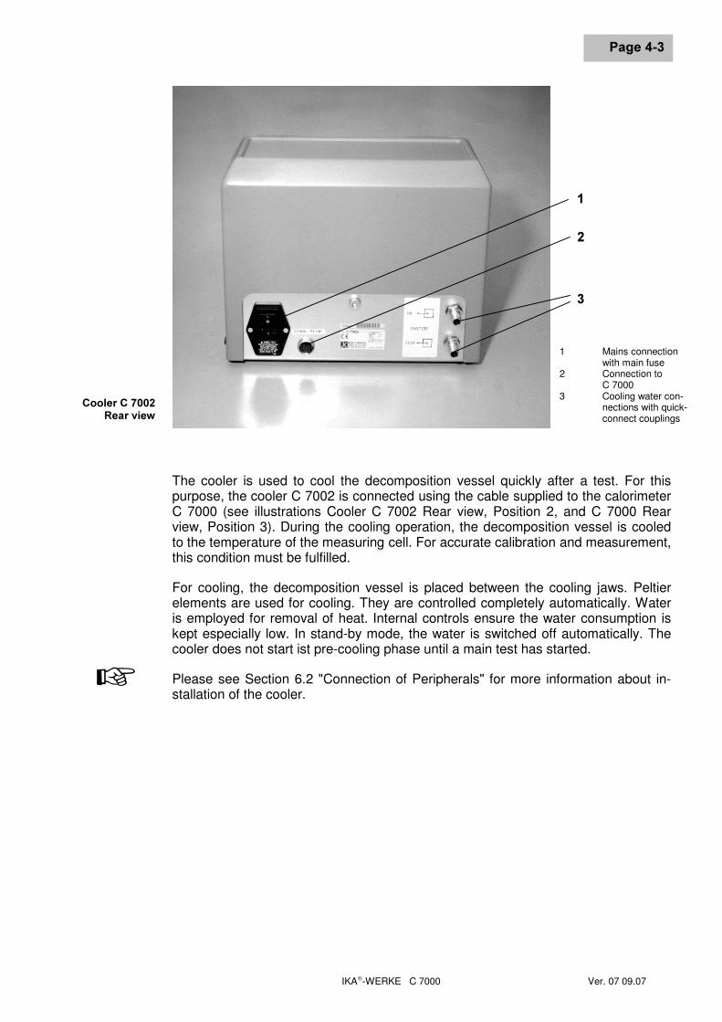
The cooler is used to cool the decomposition vessel quickly after a test. For thispurpose, the cooler C 7002 is connected using the cable supplied to the calorimeterC 7000 (see illustrations Cooler C 7002 Rear view, Position 2, and C 7000 Rearview, Position 3). During the cooling operation, the decomposition vessel is cooledto the temperature of the measuring cell. For accurate calibration and measurement,this condition must be fulfilled.
For cooling, the decomposition vessel is placed between the cooling jaws. Peltierelements are used for cooling. They are controlled completely automatically. Wateris employed for removal of heat. Internal controls ensure the water consumption iskept especially low. In stand-by mode, the water is switched off automatically. Thecooler does not start ist pre-cooling phase until a main test has started.
Please see Section 6.2 "Connection of Peripherals" for more information about in-stallation of the cooler.
&RROHU�&�����5HDU�YLHZ
�
�
�
1 Mains connectionwith main fuse
2 Connection toC 7000
3 Cooling water con-nections with quick-connect couplings
+

IKA-WERKE C 7000 Ver. 07 09.07
IKA-WERKE C 7000 Ver. 07 09.07
3DJH����
�� 3ULQFLSOHV�RI�&DORULPHWULF�0HDVXUHPHQWTo make a calorimetric measurement, a sample of a substance is burnt. In order toignite the sample, energy must be supplied from an external source. An ignitionwire, which is heated to glowing point by passing an electric current through it, per-forms this function. If the measurement is to be accurate, it is essential that thesample is completely burnt. For this reason, combustion takes place in an atmos-phere of oxygen at a pressure of 30 bar.
���� 'HWHUPLQLQJ�WKH�*URVV�&DORULILF�9DOXHIn a calorimeter combustion takes place under defined conditions. A weighed sam-ple of a substance is placed in the decomposition vessel, the sample is ignited, andthe increase in temperature of the decomposition vessel is measured. The grosscalorific value of a sample is calculated from:
• temperature increase of the decomposition vessel• heat capacity (C value) of the calorimeter system• mass of the fuel sample• heat energy that is released by burning the ignition aid and auxiliary fuel, and
also by the formation of sulphuric and nitric acids (external energy).
To optimise the combustion process, the decomposition vessel is filled with pureoxygen (99.95%). The pressure of the oxygen atmosphere in the decompositionvessel is 30 bar. The fuel sample is weighed to an accuracy of 0.1 mg using ananalytical balance.
Precise determination of the calorific value of a substance demands that combustiontakes place under precisely defined conditions. The relevant standards make thefollowing assumptions:
• any water contained in the fuel, and any water formed by the combustion ofcompounds containing hydrogen in the fuel is present in a liquid state aftercombustion;
• no oxidation of atmospheric nitrogen has taken place;
• gaseous products present after combustion consist of oxygen, nitrogen, carbondioxide and sulphur dioxide;
• solids can also be formed (e.g. ash).
Frequently, other combustion products, not foreseen by the standards, are formed.In such cases, analyses of the sample material and the combustion products arerequired to supply data for correction calculations. The standard gross calorific valueis then determined from the measured value and the analysis data.
7HVWFRQGLWLRQV
��3ULQFLSOHV�RI�&DORULPHWULF�0HDVXUHPHQW
IKA-WERKE C 7000 Ver. 07 09.07
3DJH����
The gross calorific value Ho is obtained by dividing the heat energy released byburning a solid or liquid fuel by the weight of the sample. When determining the heatenergy released, water-containing components of the fuel must be present in liquidform after combustion.
The net calorific value Hu is the gross calorific value less the condensation energyof water contained in the sample and formed by combustion. The net calorific valueis of great technical importance, because in all major applications, only the net calo-rific value can be exploited as energy.
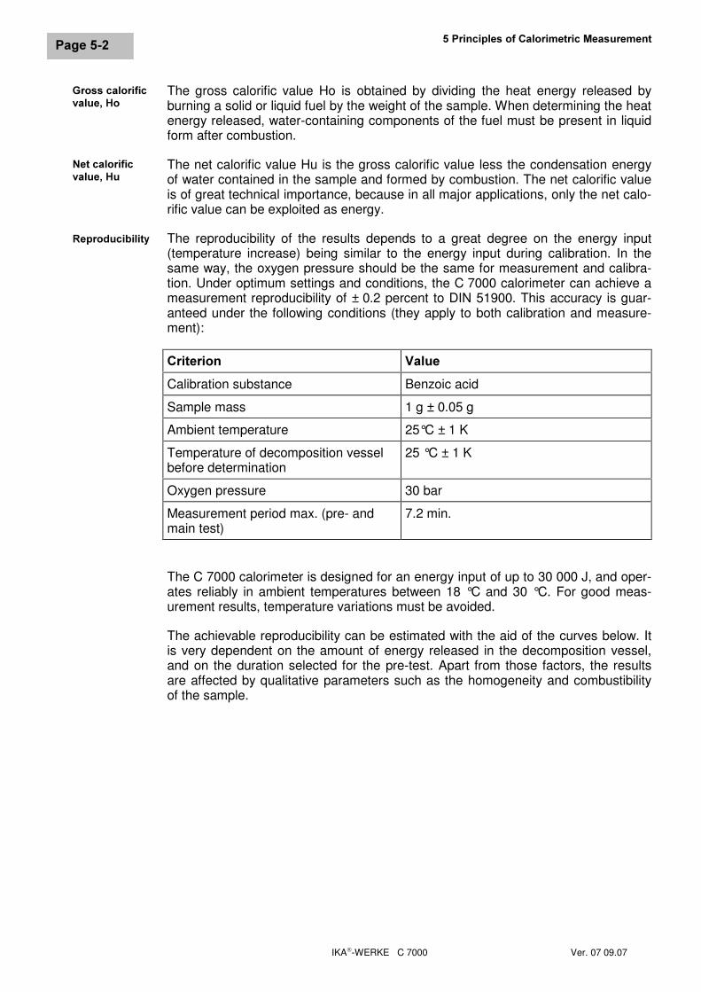
The reproducibility of the results depends to a great degree on the energy input(temperature increase) being similar to the energy input during calibration. In thesame way, the oxygen pressure should be the same for measurement and calibra-tion. Under optimum settings and conditions, the C 7000 calorimeter can achieve ameasurement reproducibility of ± 0.2 percent to DIN 51900. This accuracy is guar-anteed under the following conditions (they apply to both calibration and measure-ment):
&ULWHULRQ 9DOXHCalibration substance Benzoic acid
Sample mass 1 g ± 0.05 g
Ambient temperature 25°C ± 1 K
Temperature of decomposition vesselbefore determination
25 °C ± 1 K
Oxygen pressure 30 bar
Measurement period max. (pre- andmain test)
7.2 min.
The C 7000 calorimeter is designed for an energy input of up to 30 000 J, and oper-ates reliably in ambient temperatures between 18 °C and 30 °C. For good meas-urement results, temperature variations must be avoided.
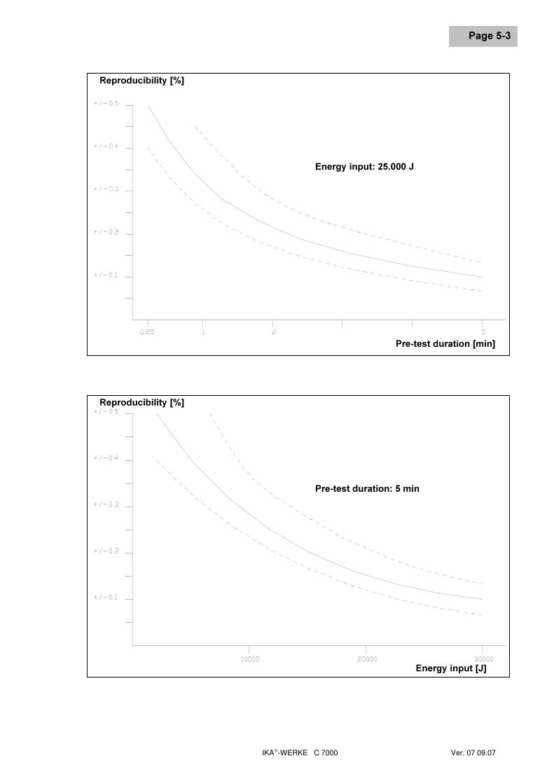
The achievable reproducibility can be estimated with the aid of the curves below. Itis very dependent on the amount of energy released in the decomposition vessel,and on the duration selected for the pre-test. Apart from those factors, the resultsare affected by qualitative parameters such as the homogeneity and combustibilityof the sample.
1HW�FDORULILFYDOXH��+X
*URVV�FDORULILFYDOXH��+R
5HSURGXFLELOLW\
IKA-WERKE C 7000 Ver. 07 09.07
3DJH����
5HSURGXFLELOLW\�>�@
3UH�WHVW�GXUDWLRQ�>PLQ@
(QHUJ\�LQSXW���������-
5HSURGXFLELOLW\�>�@
(QHUJ\�LQSXW�>-@
3UH�WHVW�GXUDWLRQ����PLQ
��3ULQFLSOHV�RI�&DORULPHWULF�0HDVXUHPHQW
IKA-WERKE C 7000 Ver. 07 09.07
3DJH����
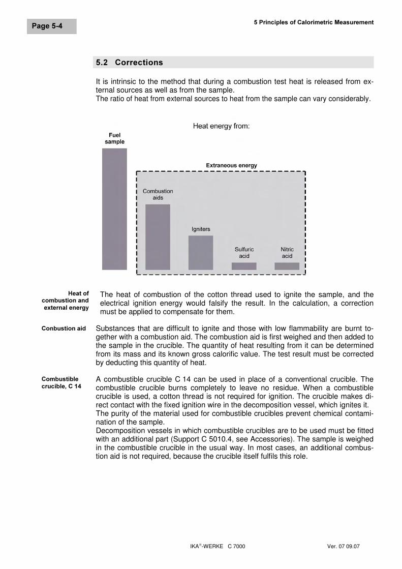
���� &RUUHFWLRQVIt is intrinsic to the method that during a combustion test heat is released from ex-ternal sources as well as from the sample.The ratio of heat from external sources to heat from the sample can vary considerably.
The heat of combustion of the cotton thread used to ignite the sample, and theelectrical ignition energy would falsify the result. In the calculation, a correctionmust be applied to compensate for them.
Substances that are difficult to ignite and those with low flammability are burnt to-gether with a combustion aid. The combustion aid is first weighed and then added tothe sample in the crucible. The quantity of heat resulting from it can be determinedfrom its mass and its known gross calorific value. The test result must be correctedby deducting this quantity of heat.
A combustible crucible C 14 can be used in place of a conventional crucible. Thecombustible crucible burns completely to leave no residue. When a combustiblecrucible is used, a cotton thread is not required for ignition. The crucible makes di-rect contact with the fixed ignition wire in the decomposition vessel, which ignites it.The purity of the material used for combustible crucibles prevent chemical contami-nation of the sample.Decomposition vessels in which combustible crucibles are to be used must be fittedwith an additional part (Support C 5010.4, see Accessories). The sample is weighedin the combustible crucible in the usual way. In most cases, an additional combus-tion aid is not required, because the crucible itself fulfils this role.
&RQEXVWLRQ�DLG
&RPEXVWLEOHFUXFLEOH��&���
+HDW�RIFRPEXVWLRQ�DQGH[WHUQDO�HQHUJ\
IKA-WERKE C 7000 Ver. 07 09.07
3DJH����
Almost all substances that are tested contain some sulphur and nitrogen. Under theconditions employed for calorimetric measurements, sulphur and nitrogen burn toSO2, SO3 and NOx. In combination with water from combustion and moisture fromthe sample, sulphuric acid and nitric acid are formed and heat of solution is devel-oped. The influence of the heat of solution must be taken into account when calcu-lating the standard calorific value.
To obtain a defined end condition, and to quantitatively record all acids, ca. 5 ml ofdistilled water or other suitable absorption liquid are added to the decompositionvessel. The gases resulting from combustion form acids with this absorption liquidand any water resulting from combustion. After combustion, the decomposition ves-sel is rinsed thoroughly with distilled water, to collect any condensate that has set-tled on the walls of the vessel. The acid content of this solution can be determinedusing suitable equipment.You can obtain details of suitable equipment for the purpose from IKA or from yourauthorised dealer.
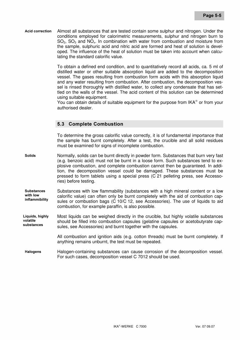
���� &RPSOHWH�&RPEXVWLRQTo determine the gross calorific value correctly, it is of fundamental importance thatthe sample has burnt completely. After a test, the crucible and all solid residuesmust be examined for signs of incomplete combustion.
Normally, solids can be burnt directly in powder form. Substances that burn very fast(e.g. benzoic acid) must not be burnt in a loose form. Such substances tend to ex-plosive combustion, and complete combustion cannot then be guaranteed. In addi-tion, the decomposition vessel could be damaged. These substances must bepressed to form tablets using a special press (C 21 pelleting press, see Accesso-ries) before testing.
Substances with low flammability (substances with a high mineral content or a lowcalorific value) can often only be burnt completely with the aid of combustion cap-sules or combustion bags (C 10/C 12, see Accessories). The use of liquids to aidcombustion, for example paraffin, is also possible.
Most liquids can be weighed directly in the crucible, but highly volatile substancesshould be filled into combustion capsules (gelatine capsules or acetobutyrate cap-sules, see Accessories) and burnt together with the capsules.
All combustion and ignition aids (e.g. cotton threads) must be burnt completely. Ifanything remains unburnt, the test must be repeated.
Halogen-containing substances can cause corrosion of the decomposition vessel.For such cases, decomposition vessel C 7012 should be used.
6ROLGV
6XEVWDQFHVZLWK�ORZLQIODPPLELOLW\
+DORJHQV
$FLG�FRUUHFWLRQ
/LTXLGV��KLJKO\YRODWLOHVXEVWDQFHV
��3ULQFLSOHV�RI�&DORULPHWULF�0HDVXUHPHQW
IKA-WERKE C 7000 Ver. 07 09.07
3DJH����
���� &DOLEUDWLRQFor the most precise results, the calorimeter should be calibrated during commis-sioning, following service work, when parts have been replaced, and at defined in-tervals. The purpose of calibration is to re-determine the thermal capacity of thecalorimeter system (C value).
5HJXODU�FDOLEUDWLRQ�LV�HVVHQWLDO�WR�PDLQWDLQ�PHDVXUHPHQW�DFFXUDF\�Calibration is carried out by burning a known quantity of a reference substance inthe decomposition vessel under test conditions. Since the calorific value of the ref-erence substance is known, it is possible to use the temperature increase of thedecomposition vessel to calculate its heat capacity.
The reference substance used internationally for calorimetry is benzoic acid from theNational Bureau of Standards (NBS Standard Sample 39), which has a guaranteedcalorific value.
,I�D�FDORULPHWHU�LV�XVHG�ZLWK�VHYHUDO�GHFRPSRVLWLRQ�YHVVHOV��WKH�KHDW�FDSDFLW\RI�WKH�V\VWHP�PXVW�EH�GHWHUPLQHG�ZLWK�HDFK�YHVVHO�For more detailed information on calibration, please refer to the relevant standards.
+
+
IKA-WERKE C 7000 Ver. 07 09.07
3DJH����
�� &RPPLVVLRQLQJOnce the components of the C 7000 calorimeter have been unpacked and broughtto the location chosen for the instrument (see Chapter 3, Section 3.2 "InstallationLocation"), the mains lead and peripherals can be connected.
���� &RQQHFWLQJ�WKH�PDLQV�OHDGCheck that the voltage given on the typeplate of the calorimeter corresponds to yourmains supply, then plug the mains lead into the socket on the rear of the calorimeterand to the mains socket.
���� &RQQHFWLQJ�SHULSKHUDOV:KHQ� FRQQHFWLQJ� SHULSKHUDOV�� WKH�PDLQV� VZLWFK� RI� WKH� FDORULPHWHU� PXVW� EHVZLWFKHG�RII�)RU�DOO�FRQQHFWLRQV�WR�WKH�FDORULPHWHU��XVH�RQO\�WKH�LQWHUIDFH�FDEOHV�VXSSOLHGE\�,.$ � �&RQQHFWLQJ�D�EDODQFH��SULQWHU�RU�3&For connection of a balance, a printer or an external PC, there are sockets on therear of the unit marked %DODQFH, 3ULQWHU and 3& (see Section 4.1, illustrationC 7000 Rear view).
Now connect the peripherals you will be using.
&RQQHFWLQJ�WKH�FRROHU�&�����Connect the C 7002 cooler as follows:
cCheck that the voltage given on the typeplate of the cooler corresponds to yourmains supply, then plug the mains lead into the socket on the cooler and to themains socket.
dThere are two hoses with quick-connect couplings included with the cooler. Connectthem to the ,Q and 2XW connections on the rear of the cooler.
eConnect the other end of the feed hose (,Q) to a water supply, water tap or to acooling water supply (e.g. IKA KV 500) and secure the connection. Take the drainhose (2XW) to a suitable sink and secure it there.
fUse the cable provided to connect the cooler and calorimeter at the appropriatesockets on the rear of each unit (see Chapter 4 "Description of System Compo-nents").
The C 7002 cooler is now connected to the C 7000 calorimeter.
��&RPPLVVLRQLQJ
IKA-WERKE C 7000 Ver. 07 09.07
3DJH����
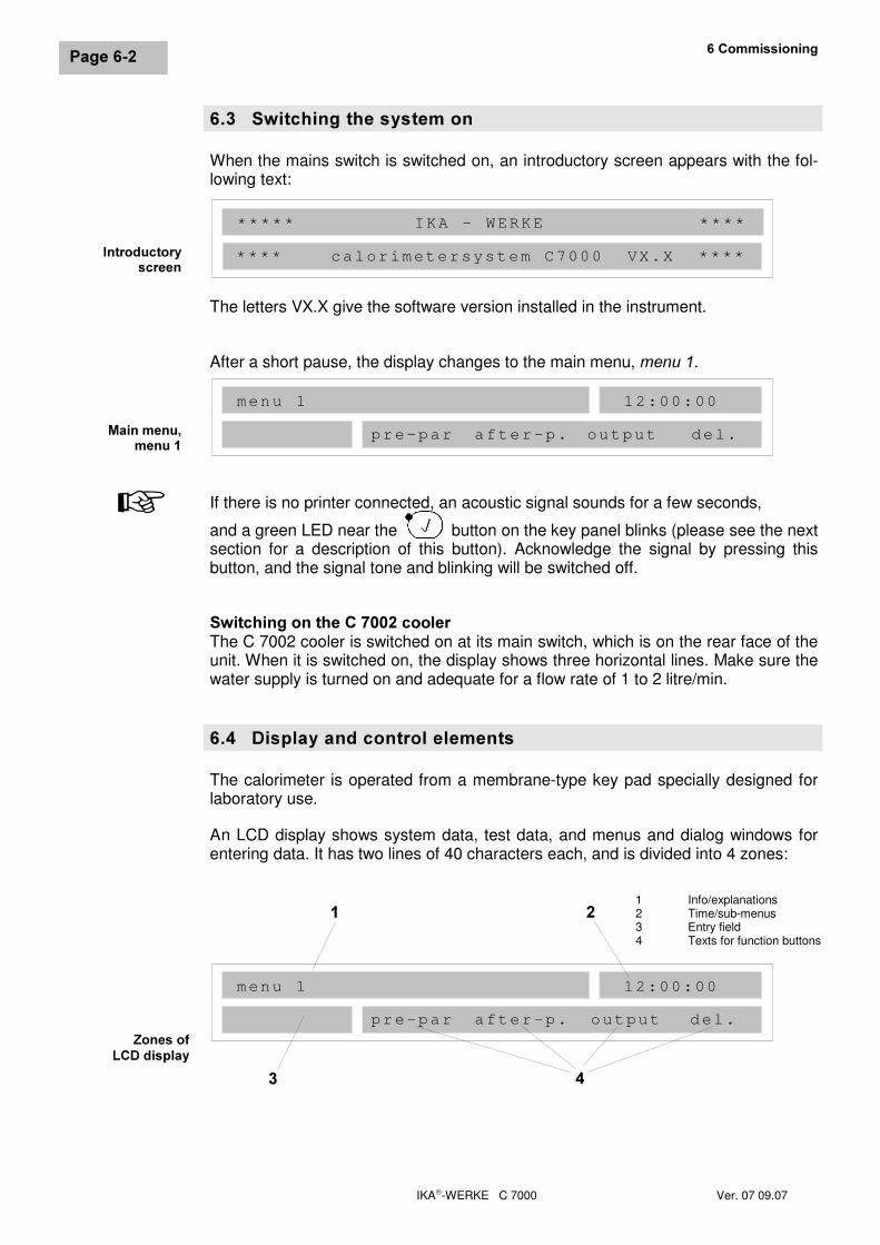
���� 6ZLWFKLQJ�WKH�V\VWHP�RQWhen the mains switch is switched on, an introductory screen appears with the fol-lowing text:
The letters VX.X give the software version installed in the instrument.
After a short pause, the display changes to the main menu, PHQX��.
If there is no printer connected, an acoustic signal sounds for a few seconds,
and a green LED near the button on the key panel blinks (please see the nextsection for a description of this button). Acknowledge the signal by pressing thisbutton, and the signal tone and blinking will be switched off.
6ZLWFKLQJ�RQ�WKH�&������FRROHUThe C 7002 cooler is switched on at its main switch, which is on the rear face of theunit. When it is switched on, the display shows three horizontal lines. Make sure thewater supply is turned on and adequate for a flow rate of 1 to 2 litre/min.
���� 'LVSOD\�DQG�FRQWURO�HOHPHQWVThe calorimeter is operated from a membrane-type key pad specially designed forlaboratory use.
An LCD display shows system data, test data, and menus and dialog windows forentering data. It has two lines of 40 characters each, and is divided into 4 zones:
=RQHV�RI/&'�GLVSOD\
menu 1
pre-par after-p. output del.
12:00:00
�
� �
1 Info/explanations2 Time/sub-menus3 Entry field4 Texts for function buttons
�
,QWURGXFWRU\VFUHHQ
0DLQ�PHQX�PHQX��
+
menu 1
pre-par after-p. output del.
12:00:00
***** IKA - WERKE ****
**** calorimetersystem C7000 VX.X ****
IKA-WERKE C 7000 Ver. 07 09.07
3DJH����
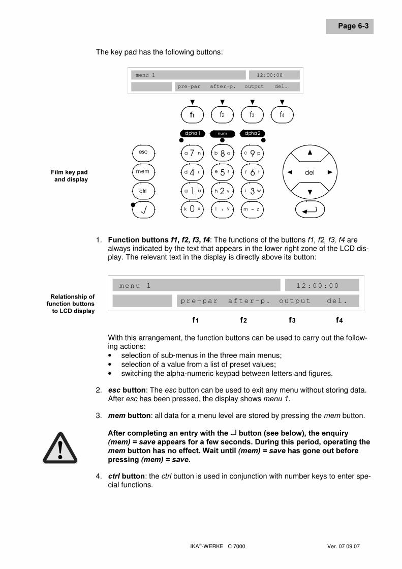
The key pad has the following buttons:
9c pesc
mem
ctrl
8b o7a n
6f t5e s4d r
3i w2h v1g u
-m z.l y0k x
f3f1 f4
alpha 2alpha 1
del
f1 f2
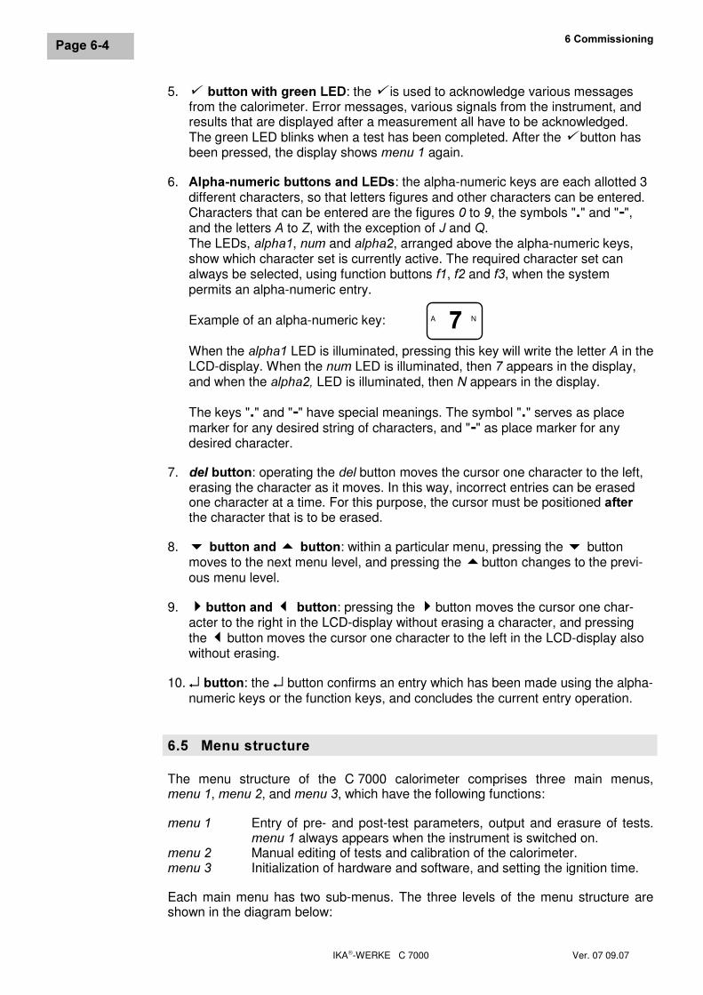
1. )XQFWLRQ�EXWWRQV�I���I���I���I�: The functions of the buttons I���I���I���I� arealways indicated by the text that appears in the lower right zone of the LCD dis-play. The relevant text in the display is directly above its button:
With this arrangement, the function buttons can be used to carry out the follow-ing actions:• selection of sub-menus in the three main menus;• selection of a value from a list of preset values;• switching the alpha-numeric keypad between letters and figures.
2. HVF�EXWWRQ: The HVF button can be used to exit any menu without storing data.After HVF has been pressed, the display shows PHQX��.
3. PHP�EXWWRQ: all data for a menu level are stored by pressing the PHP button.
$IWHU�FRPSOHWLQJ�DQ�HQWU\�ZLWK�WKH���EXWWRQ��VHH�EHORZ���WKH�HQTXLU\�PHP�� �VDYH DSSHDUV�IRU�D�IHZ�VHFRQGV��'XULQJ�WKLV�SHULRG��RSHUDWLQJ�WKHPHP�EXWWRQ�KDV�QR�HIIHFW��:DLW�XQWLO��PHP�� �VDYH�KDV�JRQH�RXW�EHIRUHSUHVVLQJ��PHP�� �VDYH�
4. FWUO�EXWWRQ: the FWUO button is used in conjunction with number keys to enter spe-cial functions.
)LOP�NH\�SDGDQG�GLVSOD\
5HODWLRQVKLS�RIIXQFWLRQ�EXWWRQVWR�/&'�GLVSOD\
menu 1
pre-par after-p. output del.
I� I� I� I�
12:00:00
menu 1
pre-par after-p. output del.
12:00:00
��&RPPLVVLRQLQJ
IKA-WERKE C 7000 Ver. 07 09.07
3DJH����
5. 9��EXWWRQ�ZLWK�JUHHQ�/(': the 9�is used to acknowledge various messagesfrom the calorimeter. Error messages, various signals from the instrument, andresults that are displayed after a measurement all have to be acknowledged.The green LED blinks when a test has been completed. After the 9�button hasbeen pressed, the display shows PHQX���again.
6. $OSKD�QXPHULF�EXWWRQV�DQG�/('V: the alpha-numeric keys are each allotted 3different characters, so that letters figures and other characters can be entered.Characters that can be entered are the figures � to �, the symbols "�" and "�",and the letters $ to =, with the exception of - and 4.The LEDs, DOSKD�, QXP and DOSKD�, arranged above the alpha-numeric keys,show which character set is currently active. The required character set canalways be selected, using function buttons I�, I� and I�, when the systempermits an alpha-numeric entry.
Example of an alpha-numeric key:
When the DOSKD� LED is illuminated, pressing this key will write the letter $ in theLCD-display. When the QXP�LED is illuminated, then � appears in the display,and when the DOSKD���LED is illuminated, then 1 appears in the display.
The keys "�" and "�" have special meanings. The symbol "�" serves as placemarker for any desired string of characters, and "�" as place marker for anydesired character.
7. GHO�EXWWRQ: operating the GHO button moves the cursor one character to the left,erasing the character as it moves. In this way, incorrect entries can be erasedone character at a time. For this purpose, the cursor must be positioned DIWHUthe character that is to be erased.
8. �EXWWRQ�DQG���EXWWRQ: within a particular menu, pressing the buttonmoves to the next menu level, and pressing the �button changes to the previ-ous menu level.
9. �EXWWRQ�DQG���EXWWRQ: pressing the �button moves the cursor one char-acter to the right in the LCD-display without erasing a character, and pressingthe �button moves the cursor one character to the left in the LCD-display alsowithout erasing.
10. ↵�EXWWRQ: the ↵ button confirms an entry which has been made using the alpha-numeric keys or the function keys, and concludes the current entry operation.
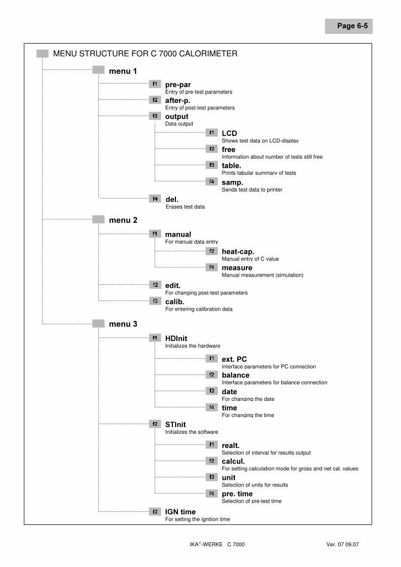
���� 0HQX�VWUXFWXUHThe menu structure of the C 7000 calorimeter comprises three main menus,PHQX��, PHQX��,�and PHQX��, which have the following functions:
PHQX�� Entry of pre- and post-test parameters, output and erasure of tests.PHQX�� always appears when the instrument is switched on.
PHQX�� Manual editing of tests and calibration of the calorimeter.PHQX�� Initialization of hardware and software, and setting the ignition time.
Each main menu has two sub-menus. The three levels of the menu structure areshown in the diagram below:
�A N
IKA-WERKE C 7000 Ver. 07 09.07
3DJH����
MENU STRUCTURE FOR C 7000 CALORIMETER
PHQX��
GHO�Erases test data
RXWSXWData output
SUH�SDUEntry of pre-test parameters
DIWHU�S�Entry of post-test parameters
/&'Shows test data on LCD-display
IUHHInformation about number of tests still free
WDEOH�Prints tabular summary of tests
VDPS�Sends test data to printer
���
���
���
���
���
���
� �
� �
PHQX��PDQXDOFor manual data entry
KHDW�FDS�Manual entry of C value
PHDVXUHManual measurement (simulation)
HGLW�For changing post-test parameters
FDOLE�For entering calibration data
���
���
� �
���
���
PHQX��+',QLWInitializes the hardware
H[W��3&Interface parameters for PC connection
EDODQFHInterface parameters for balance connection
GDWHFor changing the date
WLPHFor changing the time
67,QLWInitializes the software
UHDOW�Selection of interval for results output
FDOFXO�For setting calculation mode for gross and net cal. values
XQLWSelection of units for results
SUH��WLPHSelection of pre-test time
,*1�WLPHFor setting the ignition time
���
���
���
���
� �
���
���
���
���
���
� �
��&RPPLVVLRQLQJ
IKA-WERKE C 7000 Ver. 07 09.07
3DJH����
���� &RQILJXUDWLRQ�RI�WKH�&������&DORULPHWHUWhen it is first switched on, the fundamental settings of the calorimeter should beconfigured. This applies to all parameters that can be set in the sub-menus ofPHQX��, as follows:
• Sub-menu +',QLWH[W��3&For communication between the calorimeter and an external PC to operate cor-rectly, the interface parameters and the software protocols of the two units mustbe consistent. For the C 7000 calorimeter, the following interface parametersare available in sub-menu H[W��3& (the preset values are in bold type; they arethe interface parameters when using the IKA software &DO:LQ):
EDXG�UDWH 1200, ����, 4800, 9600 bits/s data transmission rateGDWD�ELWV 5, 6, 7, � bit length of data wordVWRS�ELWV �, 2 stop bitsSDULW\ odd, even, GLVDEOH
EDODQFHFor communication between the calorimeter and an electronic balance to oper-ate correctly, the interface parameters and the software protocols of the twounits must be consistent. The parameters for the balance must be taken fromthe balance manual.
For the C 7000 calorimeter, the sub-menu EDODQFH contains the following inter-face parameters (the preset values are in bold type):
EDXG�UDWH 1200, ����, 4800, 9600 bits/s data transmission rateGDWD�ELWV 5, 6, �, 8 bit length of data wordVWRS�ELWV �, 2 stop bitsSDULW\ RGG, even, disableEDODQ� (type) 6DUWRULXV�$&�����DQG�%3�UDQJH,
Mettler balance with RS 232C,Chyo balance
It is only possible to connect another balance if it is compatible with one of theabove models.
GDWHThe date for the calorimeter must be entered in the form (ddmmyy). Permissiblevalues are:
GG day, all dates with two figures from 01 to 31PP month, all months with two figures from 01 to 12\\ year, all years with two figures from 00 to 99)
If an incorrect entry is made, the message LQFRUUHFW�HQWU\ appears. Entries mayonly be made as numbers.
WLPHThe time must be entered in the form (hhmmss). Permissiblevalues are:
KK hours, values with two figures from 00 to 23PP minutes, values with two figures from 00 to 59VV seconds, values with two figures from 00 to 59
If an incorrect entry is made, the message LQFRUUHFW�HQWU\ appears.
IKA-WERKE C 7000 Ver. 07 09.07
3DJH����
• Sub-menu 67,QLWUHDOW�The parameter UHDOW� (real-time print out) is used to set the time interval in sec-onds for sending measured values to a printer. The values 0, 3, 12, or 24 sec-onds can be set. The preset value is 0 seconds . If the value 0 is selected, thetransmission of readings to a printer) during a test is switched off. The presenta-tion of data on the LCD-display is unaffected by the setting of this parameter.
,I�D�SULQWHU�LV�QRW�FRQQHFWHG��WKH�SDUDPHWHU�UHDOW��PXVW�EH�VHW�WR���FDOFXO�In this sub-menu, you determine the calculation mode. Possible settings are:
VWG���W standard without titrationVWG���W standard with titrationFRDO���W carbon without titrationFRDO���W carbon with titration
The calculation mode must be set EHIRUH making a measurement, because sub-sequent conversion to a different calculation mode is not possible.
The presetting is VWDQGDUG�ZLWKRXW�WLWUDWLRQ. The calculation modes VWDQGDUG andFRDO differ in that, when FRDO is set, the calculation of gross and net calorific val-ues is carried out under various conditions. If ZLWK�WLWUDWLRQ is selected, the en-ergy of acid formation is determined by titration.
XQLWThe results for gross and net calorific values can be calculated and presented inthe output protocol in several different units. The corresponding settings for theparameters XQLW are:
MRXOH J/g%78 BTU/lbN:DWW kWh/kgFDO cal/g
The preset unit is J/g.
SUH��WLPHIn this menu, one of four values can be set for the pre-test time:
���VHFRQGV���VHFRQGV����VHFRQGV����VHFRQGV
The preset value is ����VHFRQGV.7KH�ORQJHU�WKH�SUH�WHVW�WLPH��WKH�PRUH�DFFXUDWH�WKH�UHVXOW�
• ,*1�WLPHThe setting of ,*1�WLPH determines the ignition time in milliseconds for the fixedignition wire. The works setting is 1000 ms, which is normally entirely adequateto be sure that the cotton thread or the combustible crucible has ignited.The preset ignition time should only be changed if the cotton thread or the com-bustible crucible do not burn properly, or if platinum ignition wire is used. Inthese cases, the ignition time should be increased in successive steps of notmore than 100 milliseconds. However, if combustion is incomplete, first checkthe connections of the ignition wire to the electrodes in the decomposition ves-sel.
+
+
+
��&RPPLVVLRQLQJ
IKA-WERKE C 7000 Ver. 07 09.07
3DJH����
,JQLWLRQ�WLPHV�WKDW�DUH�WRR�ORQJ�FDQ�FDXVH�GHVWUXFWLRQ�RI�WKH�LJQLWLRQ�ZLUHRU�LQFUHDVHG�ZHDU�DQG�WHDU�
���� ([DPSOHV�RI�HQWULHVFor all entries that you may need to make on the calorimeter, the three examples inpresented this section are representative:
• Setting the time• Setting the time interval for output of results• Configuration for a balance
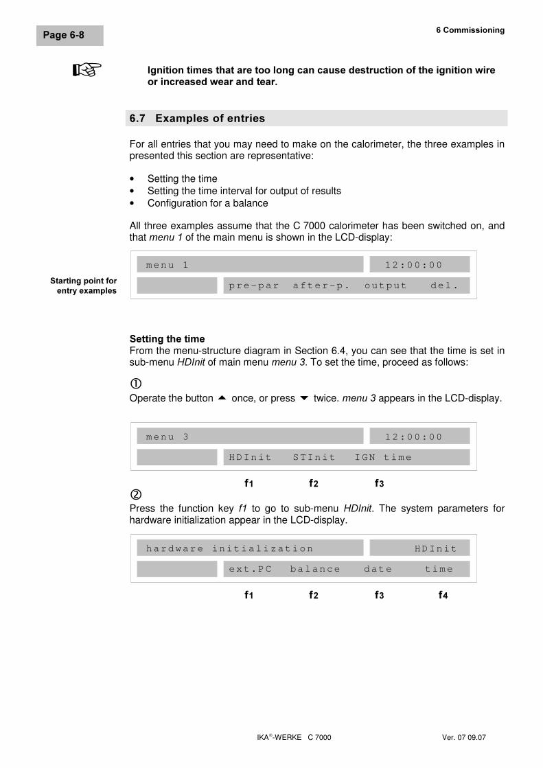
All three examples assume that the C 7000 calorimeter has been switched on, andthat PHQX�� of the main menu is shown in the LCD-display:
6HWWLQJ�WKH�WLPHFrom the menu-structure diagram in Section 6.4, you can see that the time is set insub-menu +',QLW of main menu PHQX��. To set the time, proceed as follows:
cOperate the button � once, or press twice. PHQX���appears in the LCD-display.
dPress the function key I� to go to sub-menu +',QLW. The system parameters forhardware initialization appear in the LCD-display.
6WDUWLQJ�SRLQW�IRUHQWU\�H[DPSOHV
menu 1
pre-par after-p. output del.
12:00:00
menu 3
HDInit STInit IGN time
I� I� I�
12:00:00
hardware initialization
ext.PC balance date time
I� I� I� I�
HDInit
+
IKA-WERKE C 7000 Ver. 07 09.07
3DJH����
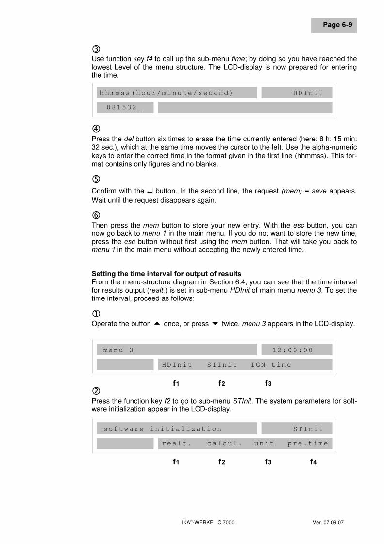
eUse function key I� to call up the sub-menu WLPH; by doing so you have reached thelowest Level of the menu structure. The LCD-display is now prepared for enteringthe time.
fPress the GHO button six times to erase the time currently entered (here: 8 h: 15 min:32 sec.), which at the same time moves the cursor to the left. Use the alpha-numerickeys to enter the correct time in the format given in the first line (hhmmss). This for-mat contains only figures and no blanks.
gConfirm with the ↵ button. In the second line, the request �PHP�� �VDYH appears.Wait until the request disappears again.
hThen press the PHP button to store your new entry. With the HVF button, you cannow go back to PHQX�� in the main menu. If you do not want to store the new time,press the HVF button without first using the PHP button. That will take you back toPHQX���in the main menu without accepting the newly entered time.
6HWWLQJ�WKH�WLPH�LQWHUYDO�IRU�RXWSXW�RI�UHVXOWVFrom the menu-structure diagram in Section 6.4, you can see that the time intervalfor results output (UHDOW�) is set in sub-menu +',QLW of main menu PHQX��. To set thetime interval, proceed as follows:
cOperate the button � once, or press twice. PHQX���appears in the LCD-display.
dPress the function key I� to go to sub-menu 67,QLW. The system parameters for soft-ware initialization appear in the LCD-display.
hhmmss(hour/minute/second)
081532_
HDInit
menu 3
HDInit STInit IGN time
I� I� I�
12:00:00
software initialization
realt. calcul. unit pre.time
I� I� I� I�
STInit
��&RPPLVVLRQLQJ
IKA-WERKE C 7000 Ver. 07 09.07
3DJH�����
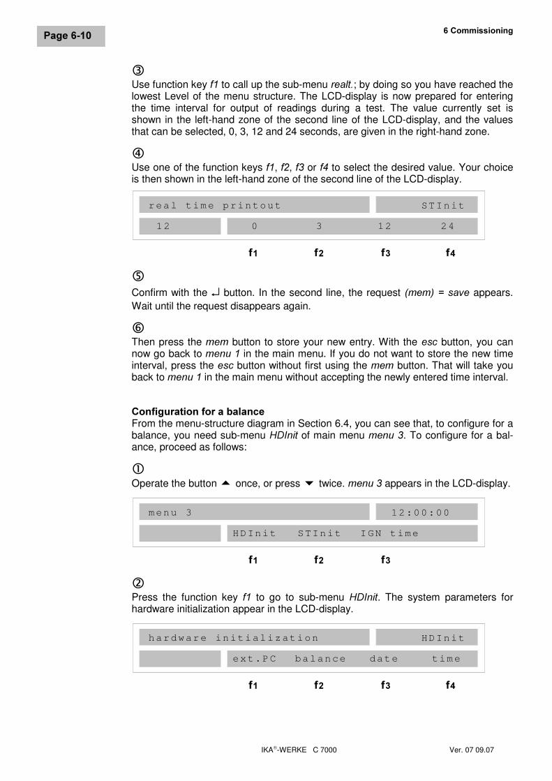
eUse function key I� to call up the sub-menu UHDOW�; by doing so you have reached thelowest Level of the menu structure. The LCD-display is now prepared for enteringthe time interval for output of readings during a test. The value currently set isshown in the left-hand zone of the second line of the LCD-display, and the valuesthat can be selected, 0, 3, 12 and 24 seconds, are given in the right-hand zone.
fUse one of the function keys I�, I�, I� or I� to select the desired value. Your choiceis then shown in the left-hand zone of the second line of the LCD-display.
gConfirm with the ↵ button. In the second line, the request �PHP�� �VDYH appears.Wait until the request disappears again.
hThen press the PHP button to store your new entry. With the HVF button, you cannow go back to PHQX�� in the main menu. If you do not want to store the new timeinterval, press the HVF button without first using the PHP button. That will take youback to PHQX���in the main menu without accepting the newly entered time interval.
&RQILJXUDWLRQ�IRU�D�EDODQFHFrom the menu-structure diagram in Section 6.4, you can see that, to configure for abalance, you need sub-menu +',QLW of main menu PHQX��. To configure for a bal-ance, proceed as follows:
cOperate the button � once, or press twice. PHQX���appears in the LCD-display.
dPress the function key I� to go to sub-menu +',QLW. The system parameters forhardware initialization appear in the LCD-display.
real time printout
0 3 12 24
I� I� I� I�
STInit
12
menu 3
HDInit STInit IGN time
I� I� I�
12:00:00
hardware initialization
ext.PC balance date time
I� I� I� I�
HDInit
IKA-WERKE C 7000 Ver. 07 09.07
3DJH�����
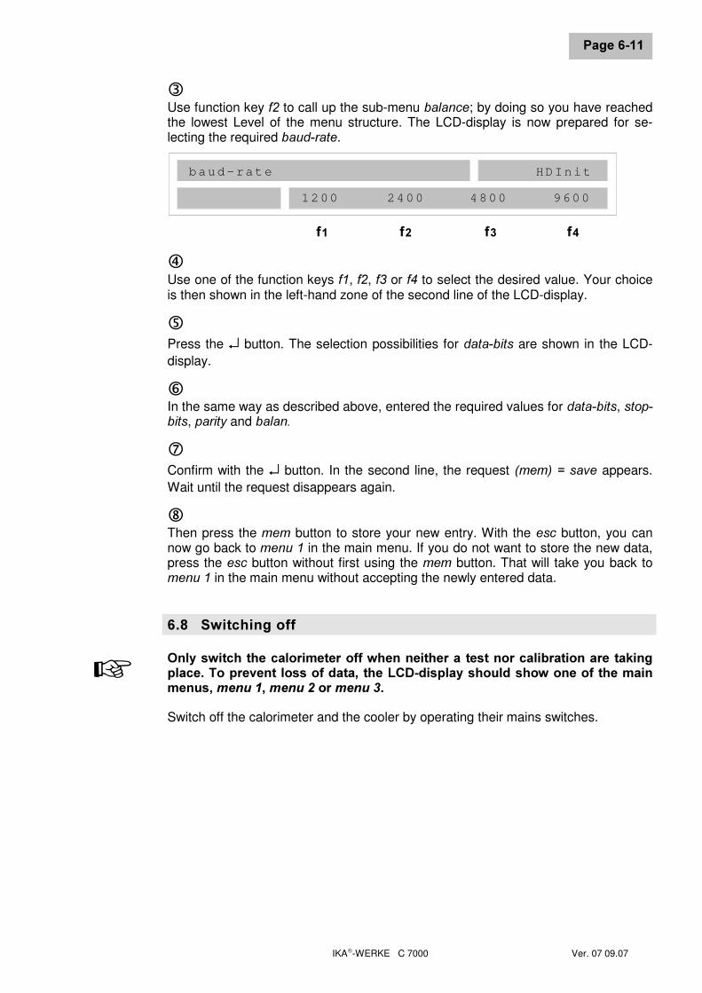
eUse function key I� to call up the sub-menu EDODQFH; by doing so you have reachedthe lowest Level of the menu structure. The LCD-display is now prepared for se-lecting the required EDXG�UDWH.
fUse one of the function keys I�, I�, I� or I� to select the desired value. Your choiceis then shown in the left-hand zone of the second line of the LCD-display.
gPress the ↵ button. The selection possibilities for GDWD�ELWV are shown in the LCD-display.
hIn the same way as described above, entered the required values for GDWD�ELWV, VWRS�ELWV, SDULW\ and EDODQ�iConfirm with the ↵ button. In the second line, the request �PHP�� �VDYH appears.Wait until the request disappears again.
jThen press the PHP button to store your new entry. With the HVF button, you cannow go back to PHQX�� in the main menu. If you do not want to store the new data,press the HVF button without first using the PHP button. That will take you back toPHQX���in the main menu without accepting the newly entered data.
���� 6ZLWFKLQJ�RII2QO\�VZLWFK�WKH�FDORULPHWHU�RII�ZKHQ�QHLWKHU�D�WHVW�QRU�FDOLEUDWLRQ�DUH� WDNLQJSODFH��7R�SUHYHQW�ORVV�RI�GDWD��WKH�/&'�GLVSOD\�VKRXOG�VKRZ�RQH�RI�WKH�PDLQPHQXV��PHQX����PHQX���RU�PHQX���Switch off the calorimeter and the cooler by operating their mains switches.
+
baud-rate
1200 2400 4800 9600
I� I� I� I�
HDInit

IKA-WERKE C 7000 Ver. 07 09.07
IKA-WERKE C 7000 Ver. 07 09.07
3DJH����
�� 3UHSDUDWLRQ�DQG�&DUU\LQJ�2XW�0HDVXUHPHQWVThe term "measurements" as used here means both measurements for calibratingthe instrument (calibration measurements) and measurements made to determine agross calorific value. The difference lies mainly in the evaluation of the results,preparation and execution are almost identical for both types of measurement.
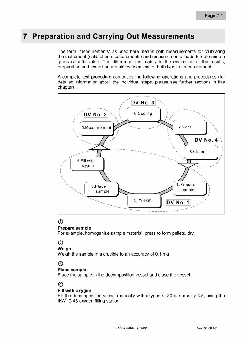
A complete test procedure comprises the following operations and procedures (fordetailed information about the individual steps, please see further sections in thischapter):
c3UHSDUH�VDPSOHFor example, homogenise sample material, press to form pellets, dry
d:HLJKWeigh the sample in a crucible to an accuracy of 0.1 mg
e3ODFH�VDPSOHPlace the sample in the decomposition vessel and close the vessel .
f)LOO�ZLWK�R[\JHQFill the decomposition vessel manually with oxygen at 30 bar, quality 3.5, using theIKA C 48 oxygen filling station.
5.Measurement
6.Cooling
7.Vent
8.C lean
1.Preparesample
3.P lacesample
4.Fill withoxygen
2. W eigh '9�1R���
'9�1R���
'9�1R���
'9�1R���
��3UHSDUDWLRQ�DQG�&DUU\LQJ�2XW�0HDVXUHPHQWV
IKA-WERKE C 7000 Ver. 07 09.07
6HLWH����
g0HDVXUHPHQWIn the C 7000 calorimeter, measurement is fully automatic.
h&RROLQJThe decomposition vessel is removed from the C 7000 calorimeter and placed in theC 7002 cooler, where it is automatically cooled to the temperature of the calorimeter.
i9HQWThe decomposition vessel is vented using the C 7010.8 vent handle or venting sta-tion C 7030.
j&OHDQClean and check the decomposition vessel as described in Section 7.6.
2SWLPLVLQJ�XVH�RI�WKH�FDORULPHWHUAs can be seen in the diagram, a complete test procedure can be sub-divided intoseveral phases. To make maximum use of the calorimeter, you need four decompo-sition vessels (DV No. 1 to DV No. 4 ) which are used as follows:
As one decomposition vessel is being prepared for a test (steps 1 to 4 in the cycle ofoperations), a second vessel is undergoing a test (step 5 in the cycle of operations).At the same time, a third decomposition vessel is cooling (step 6 in the cycle of op-erations), while the fourth is being vented and cleaned (steps 7 and 8 ).
By using four vessels in parallel in this way, well over 100 tests can be carried outwith one calorimeter in a single day. By using two or three decomposition vessels ina similar manner, a proportionately smaller time saving can be achieved.
To obtain the most accurate results, it is essential to observe the cycle of operationsshown above.
���� 5HFRPPHQGDWLRQV�IRU�FDOLEUDWLRQBefore precise measurements can be made with the calorimeter, it must be cali-brated. To calibrate the instrument, tablets of FHUWLILHG�EHQ]RLF�DFLG�(see accesso-ries) with a known calorific value are burnt. This test is used to determine the quan-tity of heat required to raise the temperature of the calorimeter by 1 Kelvin. This isknown as the heat capacity (C value) of the system. This constant is needed later tocalculate gross calorific values.The heat capacity is influenced both by the measuring cell and by the decompositionvessel. ). It has a substantial influence on the gross calorific value being determined,and must be re-established from time to time, particularly at commissioning, follow-ing servicing and when parts are replaced.
+
IKA-WERKE C 7000 Ver. 07 09.07
3DJH����
,I� VHYHUDO� GHFRPSRVLWLRQ� YHVVHOV� DUH� XVHG� LQ� D�PHDVXULQJ� FHOO�� WKH� KHDW� FD�SDFLW\�RI�WKH�V\VWHP�PXVW�EH�GHWHUPLQHG�E\�FDOLEUDWLRQ�ZLWK�HDFK�GHFRPSRVL�WLRQ�YHVVHO��$�GHFRPSRVLWLRQ�YHVVHO�PXVW�RQO\�EH�XVHG�LQ�D�PHDVXULQJ�FHOO�LQZKLFK�LW�KDV�EHHQ�FDOLEUDWHG�Calibration must be carried out under conditions similar to those that will be used forsubsequent tests. If combustion tests are to be carried out with absorption liquid(e.g. distilled water or a solution) in the decomposition vessel, then calibrationshould be carried out with the same quantity of the same substance.
5HFRPPHQGDWLRQV�IRU�FDOLEUDWLRQ• At a starting temperature of 25 °C, the C 7000 calorimeter has a maximum tem-
perature increase of 25 K. For accurate results, a combustion test should yield atemperature increase of approximately 20 Kelvin. If you do not use benzoic acidfor calibration, the quantity of material should be adjusted to meet this condition.
• For calibration, use benzoic acid (accessory C 723) compressed to a pellet.Weigh out approximately 1 g, this corresponds to a temperature increase ofca. 20 K.
• Calorific-value determinations must yield approximately the same temperatureincrease as calibration. The optimum sample quantity must be found by makingseveral tests if necessary.
• The pre-test time should be at least 120 seconds.
• When calibrating to DIN, the C value is specified as the average of at least 5calibration tests. Individual results should only be used in calculating the aver-age if the difference between the highest and lowest values (scatter) is not morethan 0.4% of the average.If the scatter is greater, then the result which is farthest from the average is dis-carded first. A sixth calibration test must now be carried out. The result of thisdetermination must not deviate by more than 0.2% from the average of the fourvalid results. For further details, please see the relevant standard.
• In the calorimeter, the C value from the last calibration of a decomposition ves-sel is stored in memory. If several calibration tests are used to determine theC value (e.g. when calibrating to DIN), the calculated average C value for thisdecomposition vessel must be entered manually before carrying out a calorificvalue determination.
1RWHV�RQ�WKH�&�YDOXHBecause a calorimeter can operate in a wide range of ambient temperatures, theC value of a system must be seen as WHPSHUDWXUH�GHSHQGHQW. This fact must betaken into account both during calibration and during normal testing. The calibrationvalues printed out use 25 °C as reference temperature. This applies also to manu-ally entered C values. When carrying out combustion tests, the C value must becorrected to the current ambient temperature (temperature of the metal casing at thestart of combustion). This also explains why the C value printed after a test does notagree with the value entered manually by the user.
+
��3UHSDUDWLRQ�DQG�&DUU\LQJ�2XW�0HDVXUHPHQWV
IKA-WERKE C 7000 Ver. 07 09.07
6HLWH����
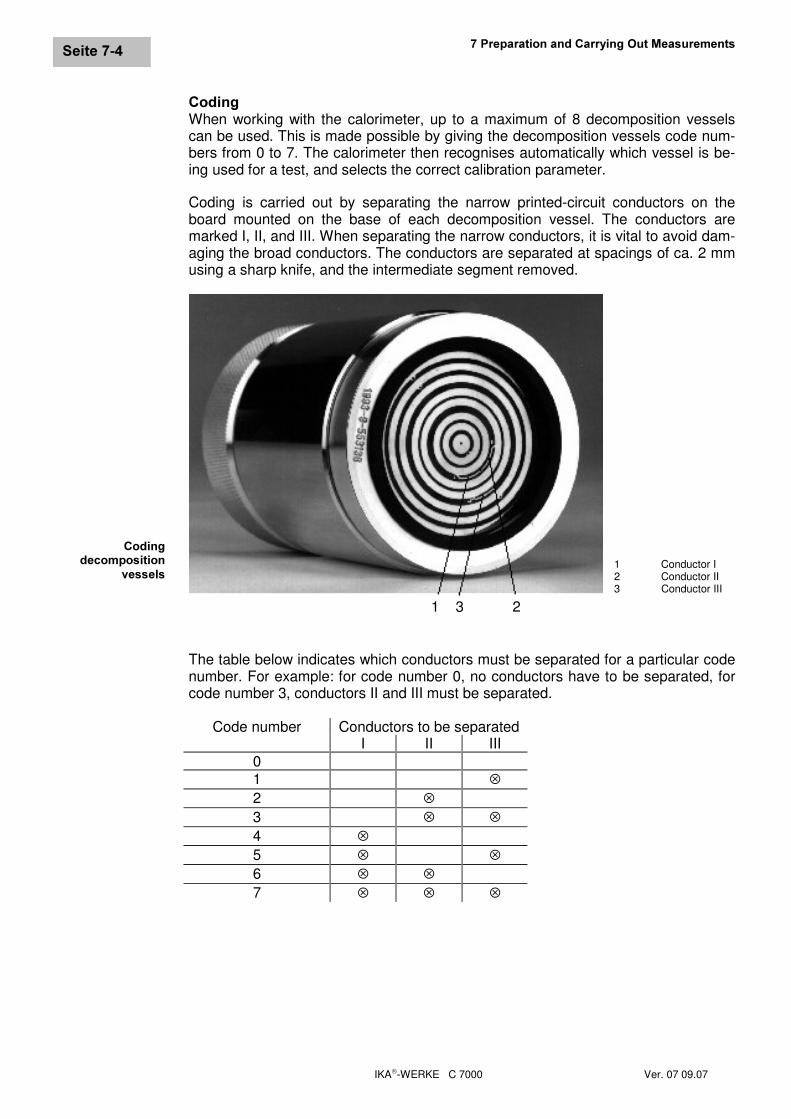
&RGLQJWhen working with the calorimeter, up to a maximum of 8 decomposition vesselscan be used. This is made possible by giving the decomposition vessels code num-bers from 0 to 7. The calorimeter then recognises automatically which vessel is be-ing used for a test, and selects the correct calibration parameter.
Coding is carried out by separating the narrow printed-circuit conductors on theboard mounted on the base of each decomposition vessel. The conductors aremarked I, II, and III. When separating the narrow conductors, it is vital to avoid dam-aging the broad conductors. The conductors are separated at spacings of ca. 2 mmusing a sharp knife, and the intermediate segment removed.
1 3 2
The table below indicates which conductors must be separated for a particular codenumber. For example: for code number 0, no conductors have to be separated, forcode number 3, conductors II and III must be separated.
Code number Conductors to be separatedI II III
01 ⊗2 ⊗3 ⊗ ⊗4 ⊗5 ⊗ ⊗6 ⊗ ⊗7 ⊗ ⊗ ⊗
&RGLQJGHFRPSRVLWLRQ
YHVVHOV 1 Conductor I2 Conductor II3 Conductor III
IKA-WERKE C 7000 Ver. 07 09.07
3DJH����
���� 1RWHV�RQ�VDPSOHV'HFRPSRVLWLRQ�YHVVHOV�&������DQG�&������DUH�QRW�SHUPLWWHG�IRU�H[SHULPHQWVRQ�IXHO�VDPSOHV�FDSDEOH�RI�H[SORGLQJ��1RWH�LQ�WKLV�UHJDUG�&KDSWHU���³)RU�\RXUVDIHW\´�The individual parts, and in particular the threading of the decomposition vesselmust be checked regularly for wear and corrosion. Note in this regard OperatingInstructions C 7010 or C 7012.
The C 7000 calorimeter is a precision instrument for routine measurement of thegross calorific value of solid and liquid substances. Accurate measurement is onlypossible if the all the individual steps in a test are carried out with care. The proce-dure as it is described in Chapter 1 “For your safety” and in the sections below musttherefore be followed precisely.
,I�PRUH�WKDQ�RQH�GHFRPSRVLWLRQ�YHVVHO�LV�EHLQJ�XVHG��WKH�UHVSHFWLYH�LQGLYLGX�DO�SDUWV�PXVW�QRW�EH�H[FKDQJHG�EHWZHHQ� WKH�YDULRXV�GHFRPSRVLWLRQ�YHVVHOV�VHH�WKH�HQJUDYLQJ�RQ�WKH�LQGLYLGXDO�SDUWV��Substances of which the combustion behavior is not known must be examined fortheir combustion behavior before combustion in the decomposition vessel C 7010 orC 7012 (danger of explosion). If you are burning XQNQRZQ VDPSOHV, leave the room
Normally, solid fuels can be burnt directly in powder form. Fast-burning substances(e.g. benzoic acid) must not be burnt in a loose form.Benzoic acid must only be burned in the form of pellets! Combustible dust and pow-der must be compressed into pellets before combustion. Oven-dry dust and powdersuch as wood chips, hay, straw, etc. burn in an explosive manner! They must bemoistened first! Readily combustible liquids with a low vapor pressure must not become in direct contact with the cotton thread (for example tetramethyl dihydrogendisiloxan)!
)DVW�EXUQLQJ�VXEVWDQFHV�WHQG�WR�H[SORVLYH�FRPEXVWLRQ��&RPSOHWH�FRPEXVWLRQLV�WKHQ�QR�ORQJHU�FHUWDLQ��,Q�DGGLWLRQ��WKH�LQQHU�ZDOO�RI�WKH�GHFRPSRVLWLRQ�YHV�VHO�PD\�EH�GDPDJHG��6XFK�VXEVWDQFHV�PXVW�EH�SUHVVHG�WR�IRUP�SHOOHWV�EHIRUHWKH\�DUH�EXUQW�The IKA C 21 pelleting press is suitable for this task.
Most liquids can be weighed directly into the crucible. Liquids that are cloudy or withseparable water must be dried or homogenised before weighing. The water contentof such samples must be determined.
For highly volatile substances, gelatine or acetobutyrate capsules (see accessories),which are filled with the fuel, must be used. The calorific value of the capsules mustbe known, so that the heat of combustion resulting from them can be taken into ac-count as external energy.
For low flammability substances and those with low calorific value, the capsulesmentioned above, or combustion bags made of polyethylene (see accessories) areused. The C 14 combustible crucibles can also be employed.Before the capsules or combustion bags are filled with the substance whose calorificvalue is to be determined, they must be weighed, so that from their mass and calo-rific value, the amount of external energy they contribute to combustion can be cal-
+
6ROLGV
/LTXLGV
+LJKO\�YRODWLOHVXEVWDQFHV
&RPEXVWLRQDLGV
+1RWHV�RQ�WKHVDPSOH
��3UHSDUDWLRQ�DQG�&DUU\LQJ�2XW�0HDVXUHPHQWV
IKA-WERKE C 7000 Ver. 07 09.07
6HLWH����
culated. The quantity of this external energy must be known for the calculation, andmust be entered with the pre-test parameters (SUH�SDU) as T�H[WU�����. The quantity ofcombustion aid used should be kept as small as possible.
Almost all substances to be analysed contain some sulphur and nitrogen. Under thepressure and temperature conditions in the decomposition vessel, they burn to formSO2, SO3 and NOx. In combination with water formed during combustion, they formsulphuric and nitric acids, and produce heat of solution. This heat of solution is takeninto account in the calculation as described in DIN 51900. To be sure that all acidsformed are quantitatively assessed, ca. 5 to 10 ml of distilled water or other suitableabsorption liquid can be added to the decomposition vessel before the test.
,Q�VXFK�FDVHV��FDOLEUDWLRQ�RI�WKH�V\VWHP�PXVW�EH�FDUULHG�RXW�ZLWK�WKLV�OLTXLG�After combustion, the water is collected and the decomposition vessel thoroughlyrinsed with distilled water. The rinsing water and the collected water are mixed, andtheir acid content investigated. If the sulphur content of the fuel and the nitric acidcorrection are known, analysis of the water is unnecessary.
7R�LQFUHDVH�WKH�ZRUNLQJ�OLIH�RI�SDUWV�VXEMHFW�WR�ZHDU�DQG�WHDU��2�ULQJV��VHDOV�HWF����ZH�UHFRPPHQG�WKDW�ZDWHU�LV�DOZD\V�DGGHG�
:KHQ�ZRUNLQJ� ZLWK� VXEVWDQFHV� FRQWDLQLQJ� KDORJHQV�� GHFRPSRVLWLRQ� YHVVHO&������PXVW�EH�XVHG�
$FLG�IRUPDWLRQ�KHDW�RI�VROXWLRQ
+
6XEVWDQFHVFRQWDLQLQJKDORJHQV
IKA-WERKE C 7000 Ver. 07 09.07
3DJH����
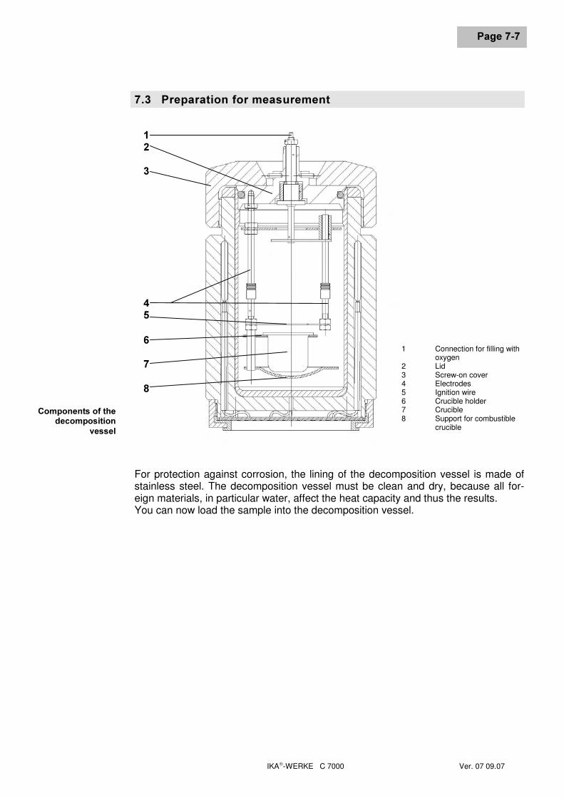
���� 3UHSDUDWLRQ�IRU�PHDVXUHPHQW
For protection against corrosion, the lining of the decomposition vessel is made ofstainless steel. The decomposition vessel must be clean and dry, because all for-eign materials, in particular water, affect the heat capacity and thus the results.You can now load the sample into the decomposition vessel.
���
�����
1 Connection for filling withoxygen
2 Lid3 Screw-on cover4 Electrodes5 Ignition wire6 Crucible holder7 Crucible8 Support for combustible
crucible
&RPSRQHQWV�RI�WKHGHFRPSRVLWLRQ
YHVVHO
��3UHSDUDWLRQ�DQG�&DUU\LQJ�2XW�0HDVXUHPHQWV
IKA-WERKE C 7000 Ver. 07 09.07
6HLWH����
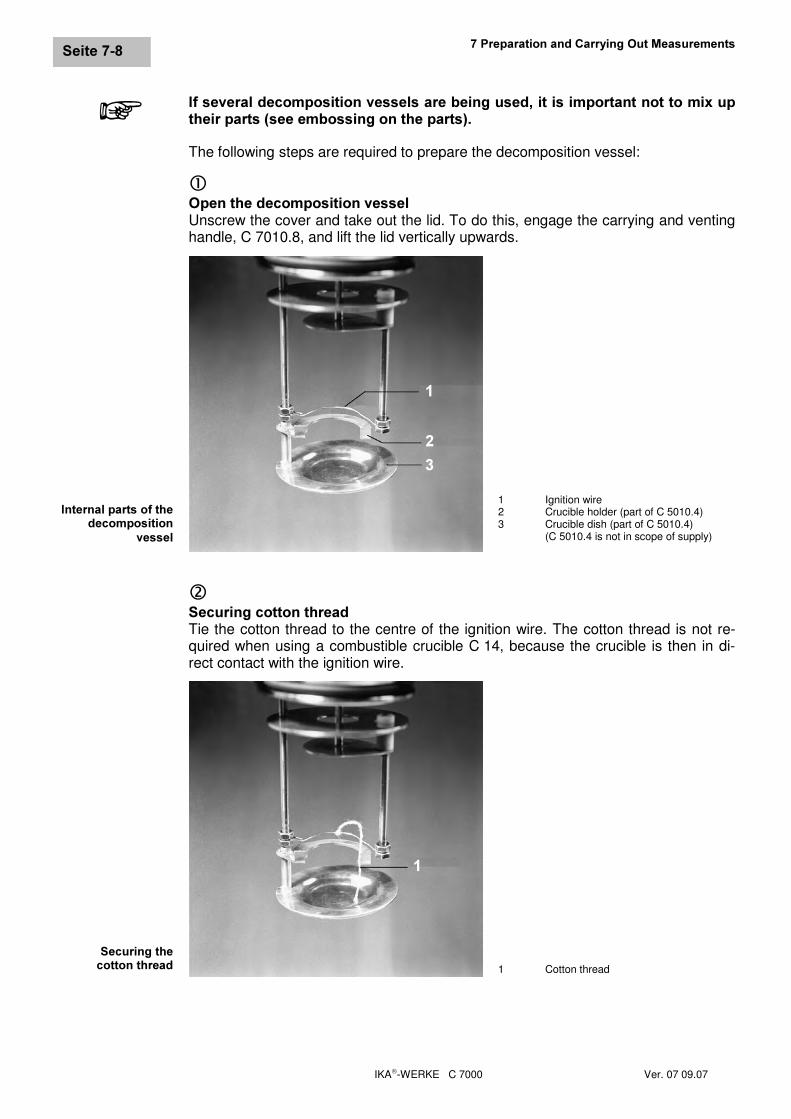
,I�VHYHUDO�GHFRPSRVLWLRQ�YHVVHOV�DUH�EHLQJ�XVHG��LW�LV�LPSRUWDQW�QRW�WR�PL[�XSWKHLU�SDUWV��VHH�HPERVVLQJ�RQ�WKH�SDUWV��The following steps are required to prepare the decomposition vessel:
c2SHQ�WKH�GHFRPSRVLWLRQ�YHVVHOUnscrew the cover and take out the lid. To do this, engage the carrying and ventinghandle, C 7010.8, and lift the lid vertically upwards.
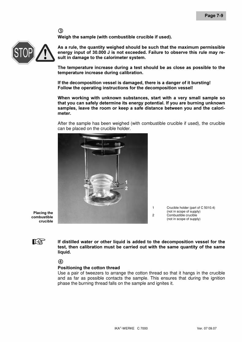
d6HFXULQJ�FRWWRQ�WKUHDGTie the cotton thread to the centre of the ignition wire. The cotton thread is not re-quired when using a combustible crucible C 14, because the crucible is then in di-rect contact with the ignition wire.
,QWHUQDO�SDUWV�RI�WKHGHFRPSRVLWLRQ
YHVVHO
1 Ignition wire2 Crucible holder (part of C 5010.4)3 Crucible dish (part of C 5010.4)
(C 5010.4 is not in scope of supply)
6HFXULQJ�WKHFRWWRQ�WKUHDG 1 Cotton thread
�
��
�
�
IKA-WERKE C 7000 Ver. 07 09.07
3DJH����
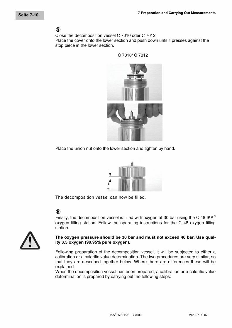
e:HLJK�WKH�VDPSOH��ZLWK�FRPEXVWLEOH�FUXFLEOH�LI�XVHG��$V�D�UXOH��WKH�TXDQWLW\�ZHLJKHG�VKRXOG�EH�VXFK�WKDW�WKH�PD[LPXP�SHUPLVVLEOHHQHUJ\�LQSXW�RI��������-�LV�QRW�H[FHHGHG��)DLOXUH�WR�REVHUYH�WKLV�UXOH�PD\�UH�VXOW�LQ�GDPDJH�WR�WKH�FDORULPHWHU�V\VWHP�7KH�WHPSHUDWXUH�LQFUHDVH�GXULQJ�D�WHVW�VKRXOG�EH�DV�FORVH�DV�SRVVLEOH�WR�WKHWHPSHUDWXUH�LQFUHDVH�GXULQJ�FDOLEUDWLRQ�,I�WKH�GHFRPSRVLWLRQ�YHVVHO�LV�GDPDJHG��WKHUH�LV�D�GDQJHU�RI�LW�EXUVWLQJ�)ROORZ�WKH�RSHUDWLQJ�LQVWUXFWLRQV�IRU�WKH�GHFRPSRVLWLRQ�YHVVHO�:KHQ�ZRUNLQJ�ZLWK�XQNQRZQ�VXEVWDQFHV�� VWDUW�ZLWK� D� YHU\� VPDOO� VDPSOH� VRWKDW�\RX�FDQ�VDIHO\�GHWHUPLQH�LWV�HQHUJ\�SRWHQWLDO��,I�\RX�DUH�EXUQLQJ�XQNQRZQVDPSOHV��OHDYH�WKH�URRP�RU�NHHS�D�VDIH�GLVWDQFH�EHWZHHQ�\RX�DQG�WKH�FDORUL�PHWHU�After the sample has been weighed (with combustible crucible if used), the cruciblecan be placed on the crucible holder.
,I�GLVWLOOHG�ZDWHU�RU�RWKHU� OLTXLG�LV�DGGHG�WR� WKH�GHFRPSRVLWLRQ�YHVVHO�IRU� WKHWHVW��WKHQ�FDOLEUDWLRQ�PXVW�EH�FDUULHG�RXW�ZLWK�WKH�VDPH�TXDQWLW\�RI�WKH�VDPHOLTXLG�f3RVLWLRQLQJ�WKH�FRWWRQ�WKUHDGUse a pair of tweezers to arrange the cotton thread so that it hangs in the crucibleand as far as possible contacts the sample. This ensures that during the ignitionphase the burning thread falls on the sample and ignites it.
3ODFLQJ�WKHFRPEXVWLEOH
FUXFLEOH
1 Crucible holder (part of C 5010.4)(not in scope of supply)
2 Combustible crucible(not in scope of supply)
+
��
��3UHSDUDWLRQ�DQG�&DUU\LQJ�2XW�0HDVXUHPHQWV
IKA-WERKE C 7000 Ver. 07 09.07
6HLWH�����
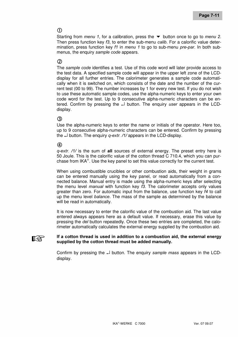
gClose the decomposition vessel C 7010 oder C 7012Place the cover onto the lower section and push down until it presses against thestop piece in the lower section.
C 7010/ C 7012
Place the union nut onto the lower section and tighten by hand.
The decomposition vessel can now be filled.
hFinally, the decomposition vessel is filled with oxygen at 30 bar using the C 48 IKA
oxygen filling station. Follow the operating instructions for the C 48 oxygen fillingstation.
7KH�R[\JHQ�SUHVVXUH�VKRXOG�EH����EDU�DQG�PXVW�QRW�H[FHHG����EDU��8VH�TXDO�LW\�����R[\JHQ���������SXUH�R[\JHQ��Following preparation of the decomposition vessel, it will be subjected to either acalibration or a calorific value determination. The two procedures are very similar, sothat they are described together below. Where there are differences these will beexplained.When the decomposition vessel has been prepared, a calibration or a calorific valuedetermination is prepared by carrying out the following steps:
IKA-WERKE C 7000 Ver. 07 09.07
3DJH�����
cStarting from PHQX��, for a calibration, press the button once to go to PHQX��.Then press function key I�, to enter the sub-menu FDOLE. For a calorific value deter-mination, press function key I� in PHQX�� to go to sub-menu SUH�SDU. In both sub-menus, the enquiry VDPSOH�FRGH appears.
dThe VDPSOH�FRGH identifies a test. Use of this code word will later provide access tothe test data. A specified sample code will appear in the upper left zone of the LCD-display for all further entries. The calorimeter generates a sample code automati-cally when it is switched on, which consists of the date and the number of the cur-rent test (00 to 99). The number increases by 1 for every new test. If you do not wishto use these automatic sample codes, use the alpha-numeric keys to enter your owncode word for the test. Up to 9 consecutive alpha-numeric characters can be en-tered. Confirm by pressing the ↵ button. The enquiry XVHU appears in the LCD-display.
eUse the alpha-numeric keys to enter the name or initials of the operator. Here too,up to 9 consecutive alpha-numeric characters can be entered. Confirm by pressingthe ↵ button. The enquiry T�H[WU����� appears in the LCD-display.
fT�H[WU�� ��� is the sum of DOO sources of external energy. The preset entry here is50 Joule. This is the calorific value of the cotton thread C 710.4, which you can pur-chase from IKA. Use the key panel to set this value correctly for the current test.
When using combustible crucibles or other combustion aids, their weight in gramscan be entered manually using the key panel, or read automatically from a con-nected balance. Manual entry is made using the alpha-numeric keys after selectingthe menu level PDQXDO with function key I�. The calorimeter accepts only valuesgreater than zero. For automatic input from the balance, use function key I� to callup the menu level EDODQFH. The mass of the sample as determined by the balancewill be read in automatically.
It is now necessary to enter the calorific value of the combustion aid. The last valueentered always appears here as a default value. If necessary, erase this value bypressing the GHO button repeatedly. Once these two entries are completed, the calo-rimeter automatically calculates the external energy supplied by the combustion aid.
,I�D�FRWWRQ�WKUHDG�LV�XVHG�LQ�DGGLWLRQ�WR�D�FRPEXVWLRQ�DLG��WKH�H[WHUQDO�HQHUJ\VXSSOLHG�E\�WKH�FRWWRQ�WKUHDG�PXVW�EH�DGGHG�PDQXDOO\�
Confirm by pressing the ↵ button. The enquiry VDPSOH�PDVV appears in the LCD-display.
+
��3UHSDUDWLRQ�DQG�&DUU\LQJ�2XW�0HDVXUHPHQWV
IKA-WERKE C 7000 Ver. 07 09.07
6HLWH�����
gHere the user also has the choice of manual entry or automatic input from a con-nected balance. Manual entries are made directly in this window using the alpha-numeric keys, or automatic input is called up by pressing function key I�. The massweighed by the balance is automatically accepted. After entry, confirm by pressingthe ↵ button. If you are preparing for a calibration, the LCD-display asks for the ref-erence calorific value, +��VWDQG� If you are preparing for a calorific-value determina-tion, the second line of the LCD-display briefly shows the enquiry �PHP�� � VDYH.When it has disappeared, pressing the PHP button stores the data entered andcloses the entries for a calorific-value determination.
If you want to check the values before you store them, you can select each pa-rameter using the arrow and function buttons and make corrections if necessary.Once the parameters have been stored, it is no longer possible to change them.
If you are carrying out a calorific-value determination, omit the next step.
hOnly when preparing for a calibration: enquiry for reference calorific value, +��VWDQG.A charge-related pre-setting in the order of 26450 J/g will be displayed. This is thecalorific value of the benzoic acid tablets supplied by IKA. If you are going to use adifferent substance for calibration, use the key panel to enter the correct value; theunits must be J/g. Confirm by pressing the ↵ button. The second line of the LCD-display briefly shows the enquiry �PHP�� �VDYH. When it has disappeared, pressingthe PHP button stores the data entered and closes the entries for a calibration.
The message "Bomb securely closed?" will appear. Ensure that the decompositionvessel is properly closed and confirm with OK.
iYou can now place the decomposition vessel in the calorimeter. Use the carryingand venting handle, C 7010.8. Place it on the decomposition vessel and turn it anti-clockwise until the handle engages. Take care not to accidentally press the ventknob, which will cause oxygen to escape. Guide the decomposition vessel into themeasuring cell, until it is standing vertically and centrally in the cell. Remove thecarrying and venting handle by turning it clockwise. Close the cover by drawing thecomplete upper section of the instrument over the measuring cell. The LCD-displaythen shows the text VDPSOH�FRGH and the parameters just entered.
Activate 6WDUWEach time 1000 ignitions have been performed using a given decomposition vessel,the following message will appear:
1000 ignitions performed with Bomb xInspect decomposition vesselor contact IKA service
This indicates that the decomposition vessel has reached a maintenance point andthat a safety check must be carried out. Confirm this message by pressing �����7$%and 2. in sequence.This message does not release the user from the responsibility of also continuouslychecking the decomposition vessel for wear and carrying out safety inspections asrequired.
+
IKA-WERKE C 7000 Ver. 07 09.07
3DJH�����
���� &DUU\LQJ�RXW�D�PHDVXUHPHQWWhen a calibration or a calorific value determination has been prepared as de-scribed above, the measuring process can be started. The VDPSOH�FRGH shown onthe LCD-display informs you of the test parameters which will be used for the meas-urement. Pressing the ↵ button starts the calibration or calorific value determination.
From now on, the C 7000 calorimeter takes control. The measurement process ismade up of a pre-test and the main test. The current phase of the test is shown onthe LCD-display. During both the pre-test and the main test, you can follow the tem-perature changes in the decomposition vessel on the LCD-display. From the start ofthe test, they are updated every 1.5 seconds. In the second line of the LCD-displayyou can also see the duration of pre-test or main test, which is indicated by an ex-tending bar.
(QG�RI�WKH�WHVWThe end of the test can be seen on the LCD-display or on the print out. As long asthe value � has not been entered in the sub-menu UHDOW� (Real time printout), duringthe test the printer will print the current temperatures at the set time intervals and theresult at the end of the test. In the first line, the LCD-display shows the temperatureincrease in Kelvin and, for a calibration, the provisional C value in the second line.
The following steps must be carried out when the test has been completed:
cThe green LED blinking near the 9�button indicates the end of the test. Acknowl-edge this by pressing the 9�button. If the button is not pressed, an acoustic signalsounds after about five seconds, as an additional means of making you aware thatthe test has ended. It sounds for about 30 seconds if it is not acknowledged. Afterthat, the LCD-display returns to PHQX�� in the main menu.
dOpen the cover of the measuring cell by lifting the upper section of the instrumentand pushing it backwards. The result of the test just carried out then appears on theLCD-display. Use the carrying and venting handle, C 7010.8, to lift the decomposi-tion vessel out of the measuring cell.
eSo that the next test can take place under the same temperature conditions, theenergy absorbed by the decomposition vessel must be removed again. The C 7002cooler fulfils this function. Place the decomposition vessel vertically in the cooler.The cooling jaws close automatically. The display shows the temperature differencebetween the decomposition vessel and the calorimeter in percent. During the cool-ing process, this value progressively approaches zero. When the temperature of thedecomposition vessel is the same as the calorimeter temperature, this is indicatedby repeated, short acoustic signals. The cooling jaws open at the same time. Re-move the decomposition vessel using the carrying and venting handle, C 7010.8.
The cooler can be manually controlled using the RSHQ�FORVH button. Pressing theRSHQ�FORVH button during the cooling process opens the cooling jaws. If the button isoperated again, the jaws close again and cooling is continued. Cooling only contin-ues as long as the decomposition vessel is at a higher temperature than the calo-rimeter.
+
��3UHSDUDWLRQ�DQG�&DUU\LQJ�2XW�0HDVXUHPHQWV
IKA-WERKE C 7000 Ver. 07 09.07
6HLWH�����
fVenting the decomposition vessel, which may contain poisonous gases should becarried out using the venting station, C 7030, which is available as an accessory. Ifthe decomposition vessel is vented using the handle, C 7010.8, this must be done ina fume cupboard. Make sure the decomposition vessel is completely vented to at-mospheric pressure, otherwise it cannot be opened.
gOpen the decomposition vessel and check the crucible for signs of incomplete com-bustion. If combustion was incomplete, discard the result and repeat the test.
hClean and inspect the decomposition vessel as described in Section 7.6.
���� 0DQXDO�UHFRUGLQJ�RI�WKH�&�YDOXHThe C value that was determined the last time a decomposition vessel was cali-brated is always stored in the calorimeter. If several calibration runs were used tocalculate the C value (e.g. when calibrating to DIN), the calculated C value for thedecomposition vessel must be entered manually before making a calorific value test.The C value is dependent on the decomposition vessel used. If the coding is used,up to eight decomposition vessels can be automatically recognised by the calo-rimeter. Then the instrument selects the appropriate C value for the current configu-ration.Starting from PHQX��, follow the steps below to enter the C value manually:
cPress the button once. PHQX�� appears in the LCD-display.
dPress the function key I� to go to the sub-menu PDQXDO. The LCD-display shows thesub-menus KHDW�FDS� (C value) and PHDVXUH�eUse function key I� to select the sub-menu KHDW�FDS� The LCD-display shows theenquiry ERPE�QR�fUse the alpha-numeric keys to enter the number of the decomposition vessel youhave used for the calibration. Later, this number will be printed on every measure-ment protocol. Confirm by pressing the ↵ button, and the enquiry for the C valueappears in the LCD-display.
gIn the second line of the LCD-display, the last C value entered is given. Erase thisentry by pressing the GHO button repeatedly. Use the alpha-numeric keys to enter theC value for the decomposition vessel previously specified.
hConfirm by pressing the ↵ button. In the second line of the LCD-display, the enquiry�PHP�� �VDYH appears briefly. Wait until this enquiry disappears again.
IKA-WERKE C 7000 Ver. 07 09.07
3DJH�����
iThen press the PHP button to store your new entry, and use the HVF button to returnto PHQX�� in the main menu.
The C value for the decomposition vessel you have specified is now stored in thecalorimeter, and will be called up automatically when you make a measurement withthis vessel.
Repeat the above procedure to enter the C value for all the other decompositionvessels you are using.
���� &OHDQLQJ�DQG�FKHFNLQJ�GHFRPSRVLWLRQ�YHVVHOV,I�WKHUH�LV�D�VXVSLFLRQ�WKDW�D�VDPSOH��RU�WKH�UHVLGXHV�RU�JDVHRXV�SURGXFWV�RIFRPEXVWLRQ� FRXOG� SUHVHQW� D� KHDOWK� KD]DUG�� WKHQ� SURWHFWLYH� SHUVRQDO� HTXLS�PHQW��H�J��JORYHV��EUHDWKLQJ�PDVN��PXVW�EH�ZRUQ��&RPEXVWLRQ�UHVLGXHV�ZKLFKDUH�D�KD]DUG�WR�KHDOWK�RU�WKH�HQYLURQPHQW�PXVW�EH�GLVSRVHG�RI�DV�KD]DUGRXVZDVWH��:H�UHIHU�\RX�H[SOLFLWO\�WR�WKH�YDOLG�UHJXODWLRQV�For accurate measurements it is absolutely essential that the decomposition vesselis clean and dry. Contaminants modify the heat capacity of a decomposition vesseland so cause inaccurate results. After every test, the inner walls of the vessel, theinternal fittings (mountings, electrodes etc.) and the combustion crucible (internallyand externally!) must be thoroughly cleaned.
In most cases it is only necessary to remove condensate from the inner walls andinternal fittings. It is then sufficient to wipe the parts carefully with an absorptive, lint-free cloth.,I� WKH�GHFRPSRVLWLRQ�YHVVHO�FDQQRW�EH�SURSHUO\�FOHDQHG�XVLQJ� WKH�PHDVXUHVGHVFULEHG� �H�J�� EXUQLQJ�� SLWWLQJ�� FRUURVLRQ� HWF���� FRQWDFW� \RXU� 7HFKQLFDO� 6HU�YLFH� 'HSDUWPHQW�� 3OHDVH� DOVR� QRWH� WKH� LQVWUXFWLRQV� JLYHQ� LQ� 6HFWLRQ� �� �)RU<RXU�6DIHW\�Combustion residues in the crucible, e.g. carbon or ash, must also be wiped offcarefully with an absorptive, lint-free cloth.
,QQHU�ZDOOV�RIWKH�YHVVHO
&UXFLEOH

IKA-WERKE C 7000 Ver. 07 09.07
IKA-WERKE C 7000 Ver. 07 09.07
3DJH����
�� (YDOXDWLRQ�RI�&DORULILF�9DOXH�7HVWVWhen a calorific value test has been completed, you can proceed to evaluating theresults. Section 8.1 explains how stored tests can be listed in a table, how you out-put or erase test results, and how you can list information about free memory forstoring new tests. You will find these functions in the sub-menu RXWSXW. The test re-sults are dependent on the post-test parameters; their meaning and how to enterthem are described in Section 8.2. Section 8.3 deals with the possibility of testsimulation.
���� 2XWSXW�DQG�WUHDWPHQW�RI�WHVW�GDWDBefore stored data can be issued and processed, the user must first state whichtests are to be called up from memory. After the appropriate menu has been acti-vated, you will be requested, in succession, to enter selection criteria for the date,sample code and sample status.
A particular test is called up by the user entering appropriate values for the date,sample code and sample status. With the aid of the two place markers "�" and "�" itis, however, also possible to select several tests at the same time. The symbol "�"serves as a place marker for any desired string of characters, while the "�" symbolfunctions as place marker for any desired single character. Both symbols can beused in the date and sample code fields, whereas sample status only considers oneof four fixed, preset values.
When the symbol "�" is entered in one of the two fields, the selection criterion is notdefined in more detail, all tests in the memory meet this criterion.
On the other hand, the symbol "�" stands for just one character within a string. Itcan, however, be used several times.
The sample status can have the following values:
• DOOall stored tests are selected, independent of sample status
• DIWHUSDUselects only tests for which post-test parameters have been entered (seeSection 8.2)
• HGLW�selects only edited tests
• SULQWHGselects only tests that have already been printed.
The individual data for date, sample code and sample status are logically linked byan AND relationship. This means that only tests that fulfil all three specified criteriawill be selected.
��(YDOXDWLRQ�RI�&DORULILF�9DOXH�7HVWV
IKA-WERKE C 7000 Ver. 07 09.07
3DJH����
([DPSOH��selection of all test data for the month of December in the year 2000:• the selection criterion for the date is "� �1200". In this way, all the days of the
month, the 12th. month, and the year 2000 will be selected;• the selection criterion for the sample code is "�", so that the sample codes of all
the tests stored in the instrument will be selected;• the selection criterion for the sample status is DOO so that, as before, all the tests
stored in the instrument will be selected.
3ULQWLQJ�D�WDEXODU�VXPPDU\�RI�WHVWVBy taking the following steps, you can print a tabular summary of all tests stored inthe instrument:
cMake sure that the printer is connected and switched on.
dChange from PHQX�� to the sub-menu RXWSXW by pressing the function button I�, andthen use function button I� to select the sub-menu WDEOH�eEnter selection criteria for the date, sample code and sample status as describedabove, and close your entries by pressing the PHP button. The printer will now startto print.
The print-out has six columns:• VDPSOH�FRGH sample code, under which all data for the test are stored• %�1R� number of the decomposition vessel used for the test• GDWH date on which the test was carried out• P�>J@ sample mass in grams• +R�>-�J@ gross calorific value in Joules per gram• +X�>-�J@ net calorific value in Joules per gram
If no post-test parameters have been entered (see Section 8.2), the remark 37�SD�UDPHWHUV�PLVVLQJ will be printed instead of the net calorific value; The net calorificvalue can only be calculated with the aid of post-test parameters. If pre-test pa-rameters have been entered but a test not yet carried out, the remark QR�PHDVXUH�PHQW�SHUIRUPHG�\HW will be printed.
At the end of the summary of tests, the C values of the decomposition vessels willbe printed. If a decomposition vessel has not been calibrated, or if the data wereentered manually, this is indicated.
,QIRUPDWLRQ�DERXW�IUHH�PHPRU\The calorimeter can store a maximum of 100 tests. Using the following procedure,you can find out at any time how much memory is still available for further tests.
cChange from PHQX�� to the sub-menu RXWSXW by pressing the function button I�,�andthen use function button I� to select the sub-menu IUHH. The message [�WHVWV� IUHHappears, where [ is the number of tests still free. An acoustic signal sounds at thesame time.
dAcknowledge this message by pressing the 9�button.
IKA-WERKE C 7000 Ver. 07 09.07
3DJH����
2XWSXW�RI�WHVW�GDWDIt is only possible to calculate net calorific values and publish them by printing or onthe LCD-display after all pre-test and post-test parameters have been entered DQGthe measurements carried out. The output contains all the parameters entered, theautomatically recorded data, and the calculated results. The latter are dependent onthe calculation mode selected. In addition, the output contains notes about the test,if appropriate.
To print test results, proceed as follows:
cMake sure that the printer is connected and switched on.
dChange from PHQX�� to the sub-menu RXWSXW by pressing the function button I�, andthen use function button I� to select the sub-menu VDPS�eEnter selection criteria for the date, sample code and sample status as describedabove, and close your entries by pressing the PHP button. The printer will now startto print.
To show test results on the LCD-display, proceed as follows:
,I� WKHUH� LV�QR�SULQWHU�FRQQHFWHG��RU� LI� WKH�SULQWHU� LV�QRW�VZLWFKHG�RQ��\RX�FDQRQO\�VKRZ�WHVW�GDWD�RQ�WKH�/&'�GLVSOD\�LI�WKH�SDUDPHWHU�UHDOW��LQ�WKH�VXE�PHQX67,QLW�RI�PHQX���LV�VHW�WR���cChange from PHQX�� to the sub-menu RXWSXW by pressing the function button I�, andthen use function button I� to select sub-menu /&'.
dEnter selection criteria for the date, sample code and sample status as describedabove, and close your entries by pressing the PHP button. The parameters appearin the LCD-display in two lines, in the same order as the printed output. The upperline contains the name and units of the parameter, and its value is shown in thelower line. To see the next parameter, use the arrow buttons � or � (in this case,both have the same effect). After all parameters have been shown, the display re-turns to the main menu.
Parameters can only be displayed in the forwards direction, it is not possible to pagebackwards. The HVF button can be used at any time to break off the procedure.
(GLWLQJ�WHVW�SDUDPHWHUVThe subsequent editing (changing) of parameters is only possible if the test resultshave been issued at least once by printing or on the LCD-display. This is to preventvalues being changed unintentionally.
��(YDOXDWLRQ�RI�&DORULILF�9DOXH�7HVWV
IKA-WERKE C 7000 Ver. 07 09.07
3DJH����
To edit the parameters of a particular test, proceed as follows:
cChange from PHQX�� to the sub-menu HGLW�, by pressing function button I�.
dEnter the sample code to identify the test you wish to change.
eUse the � or buttons to go to one or more parameters and make the desiredcorrections.
fStore the new entries by pressing the PHP button. If you want to break off the pro-cedure, press the HVF button. Changed values will then not be stored.
(UDVLQJ�WHVW�GDWDTo erase selected test data, proceed as follows:
cChange from PHQX�� to the sub-menu GHO�, by pressing function button I��dEnter selection criteria for the date, sample code and sample status as describedabove.
eClose your entries by pressing the PHP button. The tests you have selected will beerased from the memory.
By entering the following criteria, you can erase those tests that have already beenprinted once:• selection criterion for date: "�"• selection criterion for sample code: "�"• selection criterion for sample status: "SULQWHG"
���� (YDOXDWLRQ�RI�WHVWVEvaluation of test data is dependent on the post-test parameters, which can only beentered after a measurement. However, before making a measurement, the calcula-tion mode must be selected (PHQX��� ��67,QLW� �� FDOFXO�). The available settings are(see Section 6.6):
• VWG���W standard without titration• VWG���W standard with titration• FRDO���W carbon without titration• FRDO���W carbon with titration
The formulae used for calculation are mostly drawn from DIN standards. They aredescribed in detail in the relevant standards.
The sub-menu DIWHU�S� has input fields for parameters which are dependent on thecalculation mode selected. Parameters that are determined with the sample in the
+
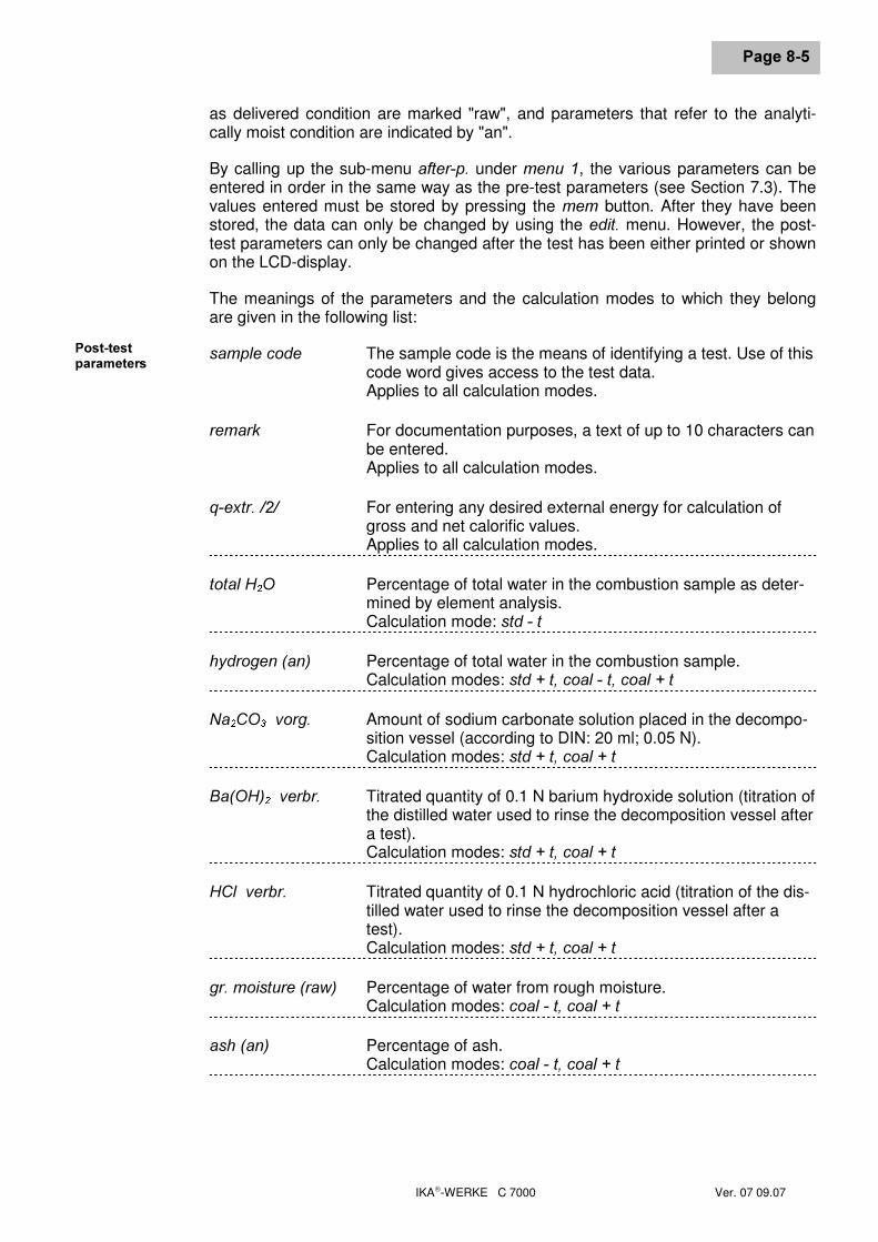
IKA-WERKE C 7000 Ver. 07 09.07
3DJH����
as delivered condition are marked "raw", and parameters that refer to the analyti-cally moist condition are indicated by "an".
By calling up the sub-menu DIWHU�S� under PHQX��, the various parameters can beentered in order in the same way as the pre-test parameters (see Section 7.3). Thevalues entered must be stored by pressing the PHP button. After they have beenstored, the data can only be changed by using the HGLW� menu. However, the post-test parameters can only be changed after the test has been either printed or shownon the LCD-display.
The meanings of the parameters and the calculation modes to which they belongare given in the following list:
VDPSOH�FRGH The sample code is the means of identifying a test. Use of thiscode word gives access to the test data.Applies to all calculation modes.
UHPDUN For documentation purposes, a text of up to 10 characters canbe entered.Applies to all calculation modes.
T�H[WU����� For entering any desired external energy for calculation ofgross and net calorific values.Applies to all calculation modes.
WRWDO�+ � 2 Percentage of total water in the combustion sample as deter-mined by element analysis.Calculation mode: VWG���W
K\GURJHQ��DQ� Percentage of total water in the combustion sample.Calculation modes: VWG���W��FRDO���W��FRDO���W
1D � &2 � ��YRUJ� Amount of sodium carbonate solution placed in the decompo-sition vessel (according to DIN: 20 ml; 0.05 N).Calculation modes: VWG���W��FRDO���W
%D�2+� � ��YHUEU� Titrated quantity of 0.1 N barium hydroxide solution (titration ofthe distilled water used to rinse the decomposition vessel aftera test).Calculation modes: VWG���W��FRDO���W
+&O��YHUEU� Titrated quantity of 0.1 N hydrochloric acid (titration of the dis-tilled water used to rinse the decomposition vessel after atest).
� Calculation modes: VWG���W��FRDO���W
JU��PRLVWXUH��UDZ� Percentage of water from rough moisture.Calculation modes: FRDO���W��FRDO���W
DVK��DQ� Percentage of ash.Calculation modes: FRDO���W��FRDO���W
3RVW�WHVWSDUDPHWHUV
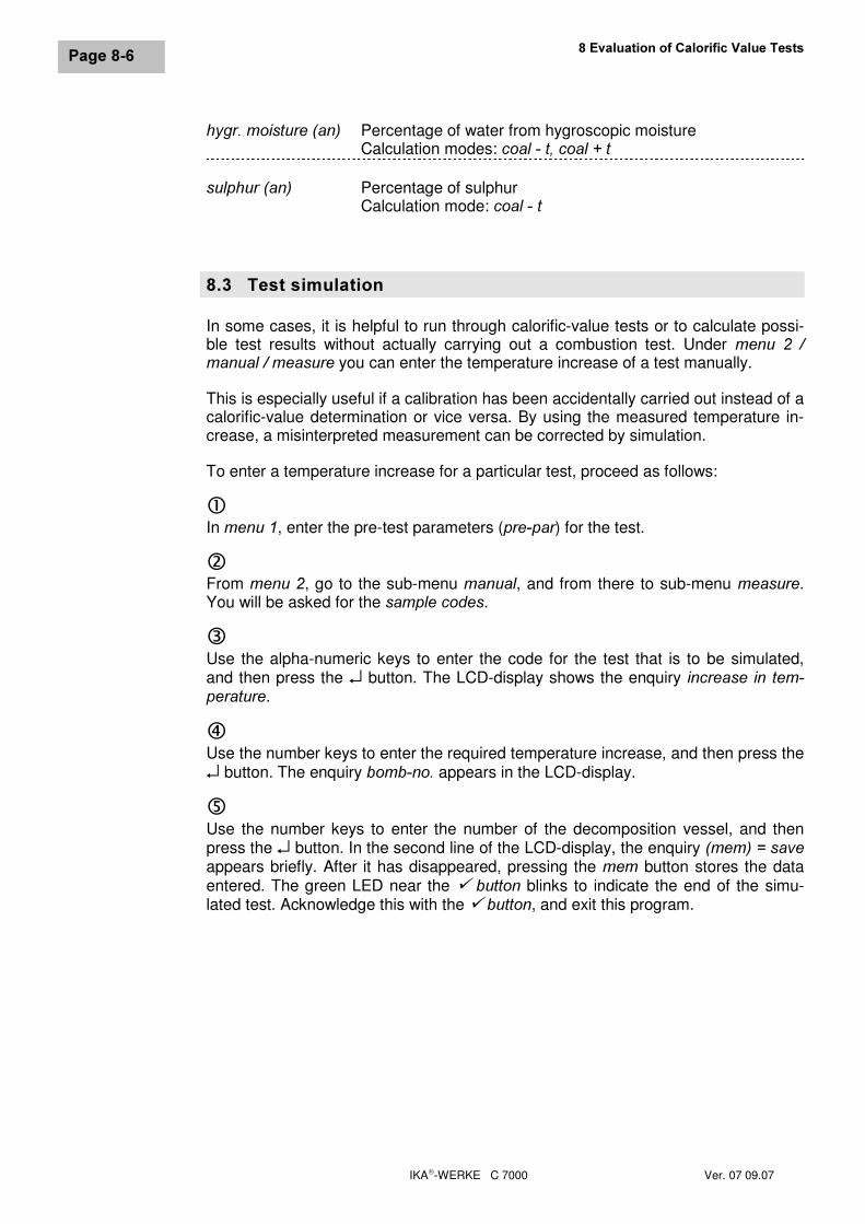
��(YDOXDWLRQ�RI�&DORULILF�9DOXH�7HVWV
IKA-WERKE C 7000 Ver. 07 09.07
3DJH����
K\JU��PRLVWXUH��DQ� Percentage of water from hygroscopic moistureCalculation modes: FRDO���W��FRDO���W
VXOSKXU��DQ� Percentage of sulphurCalculation mode: FRDO���W
���� 7HVW�VLPXODWLRQIn some cases, it is helpful to run through calorific-value tests or to calculate possi-ble test results without actually carrying out a combustion test. Under PHQX� �� �PDQXDO���PHDVXUH you can enter the temperature increase of a test manually.
This is especially useful if a calibration has been accidentally carried out instead of acalorific-value determination or vice versa. By using the measured temperature in-crease, a misinterpreted measurement can be corrected by simulation.
To enter a temperature increase for a particular test, proceed as follows:
cIn PHQX��, enter the pre-test parameters (SUH�SDU) for the test.
dFrom PHQX��, go to the sub-menu PDQXDO, and from there to sub-menu PHDVXUH.You will be asked for the VDPSOH�FRGHV.
eUse the alpha-numeric keys to enter the code for the test that is to be simulated,and then press the ↵ button. The LCD-display shows the enquiry LQFUHDVH� LQ� WHP�SHUDWXUH.
fUse the number keys to enter the required temperature increase, and then press the↵ button. The enquiry ERPE�QR� appears in the LCD-display.
gUse the number keys to enter the number of the decomposition vessel, and thenpress the ↵ button. In the second line of the LCD-display, the enquiry �PHP�� �VDYHappears briefly. After it has disappeared, pressing the PHP button stores the dataentered. The green LED near the 9�EXWWRQ blinks to indicate the end of the simu-lated test. Acknowledge this with the 9�EXWWRQ, and exit this program.
IKA-WERKE C 7000 Ver. 07 09.07
3DJH����
�� &DUH�DQG�0DLQWHQDQFH
���� 0DLQWHQDQFHTo ensure proper functioning of our instrument in continuous use, it is essential thatit is maintained at regular intervals. We can offer you a special maintenance contractto meet this need. You can obtain further information direct from our Service De-partment.
)RU�PDLQWHQDQFH�RI� WKH�GHFRPSRVLWLRQ�YHVVHO��VHH�WKH�&������&������RSHUDW�LQJ�LQVWUXFWLRQV�
���� 5HFRPPHQGDWLRQV�IRU�FOHDQLQJClean your IKA instrument only with these IKA-approved cleaning agents:
&RQWDPLQDQW &OHDQLQJ�DJHQW• Dyes Isopropanol• Building materials Water with detergent, isopropanol• Cosmetics Water with detergent, isopropanol• Foodstuffs Water with detergent• Fuels Water with detergent• Other substances Please consult IKA
1RWHVElectrical equipment must not be immersed in a cleaning agent.Stainless steel can be cleaned with commercially-available stainless steel cleaners,but do not use those containing abrasives.We recommend the wearing of protective gloves during cleaning.The operating authority is responsible for ensuring that appropriate decontaminationmeasures are taken if hazardous materials are spilt on or in the instrument.Before using any method for cleaning or decontamination other than those recom-mended by the manufacturer, consult the manufacturer to make sure that the in-tended method will not damage the instrument.
When replacing the mains cable, use a product of equivalent quality and perform-ance.

IKA-WERKE C 7000 Ver. 07 09.07
IKA-WERKE C 7000 Ver. 07 09.07
3DJH�����
���0HVVDJHV�DQG�7URXEOHVKRRWLQJThe C 7000 calorimeter is subjected to stringent quality checks during manufacture,should malfunctions occur despite this care, you will find in this section a selection ofcorrective measures for dealing with a range of fault situations. Most messages andfault indications appear on the LCD-display. They should be acknowledged with the9�button. If your attempts to correct a fault are not successful, please contact yourauthorized IKA Technical Service Department.
����� 0HVVDJHV�IURP�WKH�&������&DORULPHWHU0HVVDJH &DXVH 5HPHG\SULQWRXW�QRW�FRPSOHWH�\HW It is not possible to display a
result on the LCD if the unit stillhas a print order to process.
Check that the printer is online,otherwise wait until the printer hasfinished.
FRYHU�ZDV�RSHQHG�WHVW�DERUWHG
The cover was opened during ameasurement.
If the cover was opened during thepre-test period, the same test can berestarted.Opening the cover during the maintest invalidates the measurement.Repeat the measurement.
SULQWHU�WLPHG�RXW No data can be sent to theprinter.
Check that the printer is online. Setthe period for a real-time printout(sub-menu UHDOW�) to any value otherthan zero.Check the printer cable.
HQG�RI�HQWU\>PHP@� �VDYH
Makes you aware that allparameters in this menu havebeen entered. To store theentries, you must press the PHPbutton as soon as this messagehas disappeared.
FDOLEUDWLRQ�WHVW You have attempted to enterpost-test parameters after acalibration test. This is notpossible.
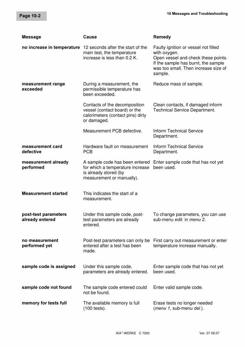
���0HVVDJHV�DQG�7URXEOHVKRRWLQJ
IKA-WERKE C 7000 Ver. 07 09.07
3DJH�����
0HVVDJH &DXVH 5HPHG\QR�LQFUHDVH�LQ�WHPSHUDWXUH 12 seconds after the start of the
main test, the temperatureincrease is less than 0.2 K.
Faulty ignition or vessel not filledwith oxygen.Open vessel and check these points.If the sample has burnt, the samplewas too small. Then increase size ofsample.
PHDVXUHPHQW�UDQJHH[FHHGHG
During a measurement, thepermissible temperature hasbeen exceeded.
Contacts of the decompositionvessel (contact board) or thecalorimeters (contact pins) dirtyor damaged.
Measurement PCB defective.
Reduce mass of sample.
Clean contacts, if damaged informTechnical Service Department.
Inform Technical ServiceDepartment.
PHDVXUHPHQW�FDUGGHIHFWLYH
Hardware fault on measurementPCB
Inform Technical ServiceDepartment.
PHDVXUHPHQW�DOUHDG\SHUIRUPHG
A sample code has been enteredfor which a temperature increaseis already stored (bymeasurement or manually).
Enter sample code that has not yetbeen used.
0HDVXUHPHQW�VWDUWHG This indicates the start of ameasurement.
SRVW�WHVW�SDUDPHWHUVDOUHDG\�HQWHUHG
Under this sample code, post-test parameters are alreadyentered.
To change parameters, you can usesub-menu HGLW� in PHQX��.
QR�PHDVXUHPHQWSHUIRUPHG�\HW
Post-test parameters can only beentered after a test has beenmade.
First carry out measurement or entertemperature increase manually.
VDPSOH�FRGH�LV�DVVLJQHG Under this sample code,parameters are already entered.
Enter sample code that has not yetbeen used.
VDPSOH�FRGH�QRW�IRXQG The sample code entered couldnot be found.
Enter valid sample code.
PHPRU\�IRU�WHVWV�IXOO The available memory is full(100 tests).
Erase tests no longer needed(PHQX��, sub-menu�GHO�).
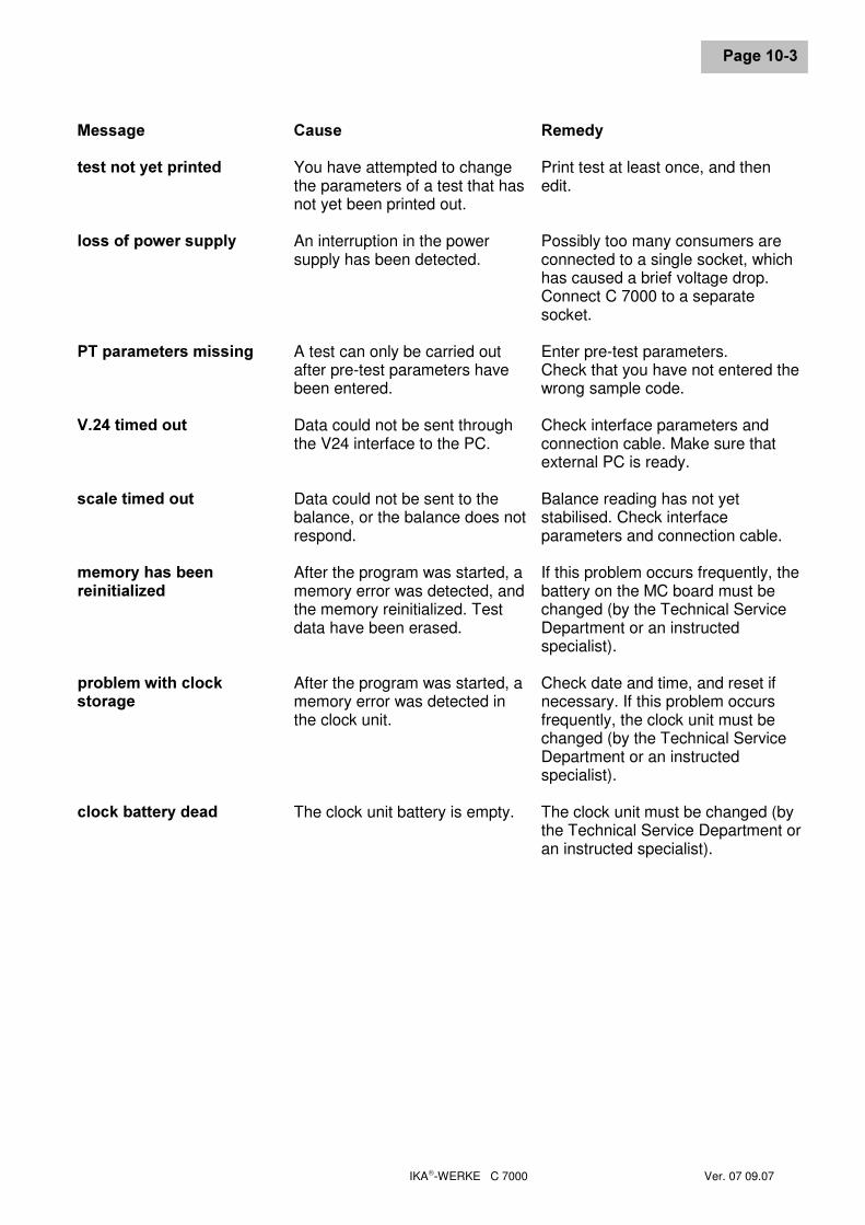
IKA-WERKE C 7000 Ver. 07 09.07
3DJH�����
0HVVDJH &DXVH 5HPHG\WHVW�QRW�\HW�SULQWHG You have attempted to change
the parameters of a test that hasnot yet been printed out.
Print test at least once, and thenedit.
ORVV�RI�SRZHU�VXSSO\ An interruption in the powersupply has been detected.
Possibly too many consumers areconnected to a single socket, whichhas caused a brief voltage drop.Connect C 7000 to a separatesocket.
37�SDUDPHWHUV�PLVVLQJ A test can only be carried outafter pre-test parameters havebeen entered.
Enter pre-test parameters.Check that you have not entered thewrong sample code.
9����WLPHG�RXW Data could not be sent throughthe V24 interface to the PC.
Check interface parameters andconnection cable. Make sure thatexternal PC is ready.
VFDOH�WLPHG�RXW Data could not be sent to thebalance, or the balance does notrespond.
Balance reading has not yetstabilised. Check interfaceparameters and connection cable.
PHPRU\�KDV�EHHQUHLQLWLDOL]HG
After the program was started, amemory error was detected, andthe memory reinitialized. Testdata have been erased.
If this problem occurs frequently, thebattery on the MC board must bechanged (by the Technical ServiceDepartment or an instructedspecialist).
SUREOHP�ZLWK�FORFNVWRUDJH
After the program was started, amemory error was detected inthe clock unit.
Check date and time, and reset ifnecessary. If this problem occursfrequently, the clock unit must bechanged (by the Technical ServiceDepartment or an instructedspecialist).
FORFN�EDWWHU\�GHDG The clock unit battery is empty. The clock unit must be changed (bythe Technical Service Department oran instructed specialist).
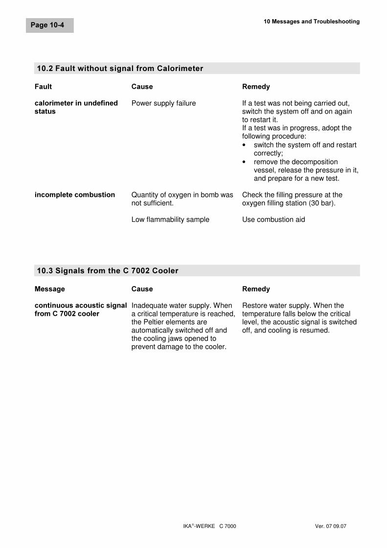
���0HVVDJHV�DQG�7URXEOHVKRRWLQJ
IKA-WERKE C 7000 Ver. 07 09.07
3DJH�����
�����)DXOW�ZLWKRXW�VLJQDO�IURP�&DORULPHWHU)DXOW &DXVH 5HPHG\FDORULPHWHU�LQ�XQGHILQHGVWDWXV
Power supply failure If a test was not being carried out,switch the system off and on againto restart it.If a test was in progress, adopt thefollowing procedure:• switch the system off and restart
correctly;• remove the decomposition
vessel, release the pressure in it,and prepare for a new test.
LQFRPSOHWH�FRPEXVWLRQ Quantity of oxygen in bomb wasnot sufficient.
Low flammability sample
Check the filling pressure at theoxygen filling station (30 bar).
Use combustion aid
�����6LJQDOV�IURP�WKH�&������&RROHU0HVVDJH &DXVH 5HPHG\FRQWLQXRXV�DFRXVWLF�VLJQDOIURP�&������FRROHU
Inadequate water supply. Whena critical temperature is reached,the Peltier elements areautomatically switched off andthe cooling jaws opened toprevent damage to the cooler.
Restore water supply. When thetemperature falls below the criticallevel, the acoustic signal is switchedoff, and cooling is resumed.
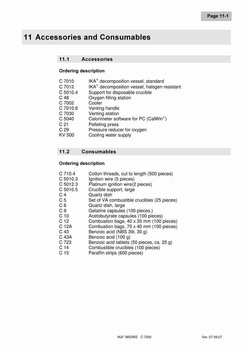
IKA-WERKE C 7000 Ver. 07 09.07
3DJH�����
���$FFHVVRULHV�DQG�&RQVXPDEOHV
����� $FFHVVRULHV2UGHULQJ�GHVFULSWLRQC 7010 IKA decomposition vessel, standardC 7012 IKA decomposition vessel, halogen resistantC 5010.4 Support for disposable crucibleC 48 Oxygen filling stationC 7002 CoolerC 7010.8 Venting handleC 7030 Venting stationC 5040 Calorimeter software for PC (CalWin)C 21 Pelleting pressC 29 Pressure reducer for oxygenKV 500 Cooling water supply
����� &RQVXPDEOHV2UGHULQJ�GHVFULSWLRQC 710.4 Cotton threads, cut to length (500 pieces)C 5010.3 Ignition wire (5 pieces)C 5012.3 Platinum ignition wire(2 pieces)C 5010.5 Crucible support, largeC 4 Quartz dishC 5 Set of VA combustible crucibles (25 pieces)C 6 Quartz dish, largeC 9 Gelatine capsules (100 pieces.)C 10 Acetobutyrate capsules (100 pieces)C 12 Combustion bags, 40 x 35 mm (100 pieces)C 12A Combustion bags, 70 x 40 mm (100 pieces)C 43 Benzoic acid (NBS 39i, 30 g)C 43A Benzoic acid (100 g)C 723 Benzoic acid tablets (50 pieces, ca. 25 g)C 14 Combustible crucibles (100 pieces)C 15 Paraffin strips (600 pieces)

IKA-WERKE C 7000 Ver. 07 09.07
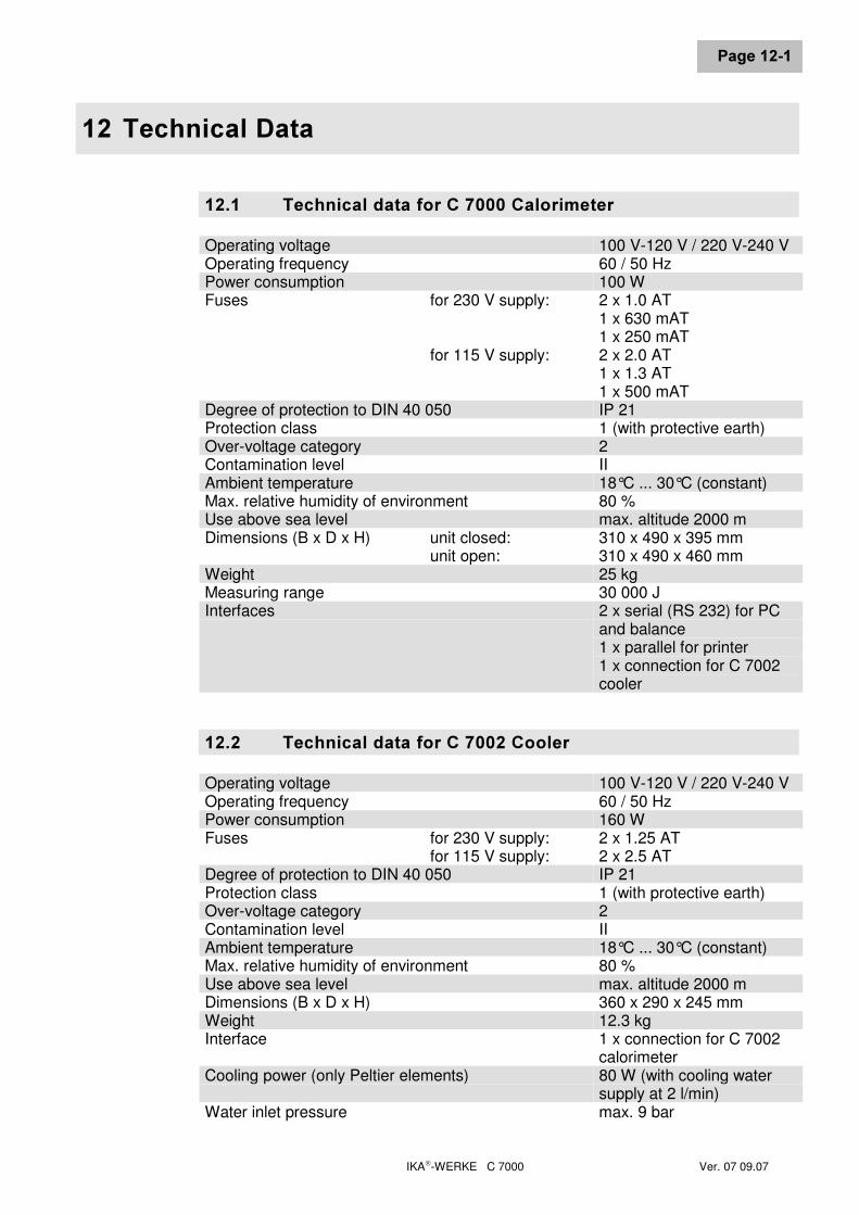
IKA-WERKE C 7000 Ver. 07 09.07
3DJH�����
���7HFKQLFDO�'DWD
����� 7HFKQLFDO�GDWD�IRU�&������&DORULPHWHUOperating voltage 100 V-120 V / 220 V-240 VOperating frequency 60 / 50 HzPower consumption 100 WFuses for 230 V supply:
for 115 V supply:
2 x 1.0 AT1 x 630 mAT1 x 250 mAT2 x 2.0 AT1 x 1.3 AT1 x 500 mAT
Degree of protection to DIN 40 050 IP 21Protection class 1 (with protective earth)Over-voltage category 2Contamination level IIAmbient temperature 18°C ... 30°C (constant)Max. relative humidity of environment 80 %Use above sea level max. altitude 2000 mDimensions (B x D x H) unit closed:
unit open:310 x 490 x 395 mm310 x 490 x 460 mm
Weight 25 kgMeasuring range 30 000 JInterfaces 2 x serial (RS 232) for PC
and balance1 x parallel for printer1 x connection for C 7002cooler
����� 7HFKQLFDO�GDWD�IRU�&������&RROHUOperating voltage 100 V-120 V / 220 V-240 VOperating frequency 60 / 50 HzPower consumption 160 WFuses for 230 V supply:
for 115 V supply:2 x 1.25 AT2 x 2.5 AT
Degree of protection to DIN 40 050 IP 21Protection class 1 (with protective earth)Over-voltage category 2Contamination level IIAmbient temperature 18°C ... 30°C (constant)Max. relative humidity of environment 80 %Use above sea level max. altitude 2000 mDimensions (B x D x H) 360 x 290 x 245 mmWeight 12.3 kgInterface 1 x connection for C 7002
calorimeterCooling power (only Peltier elements) 80 W (with cooling water
supply at 2 l/min)Water inlet pressure max. 9 bar

IKA-WERKE C 7000 Ver. 07 09.07
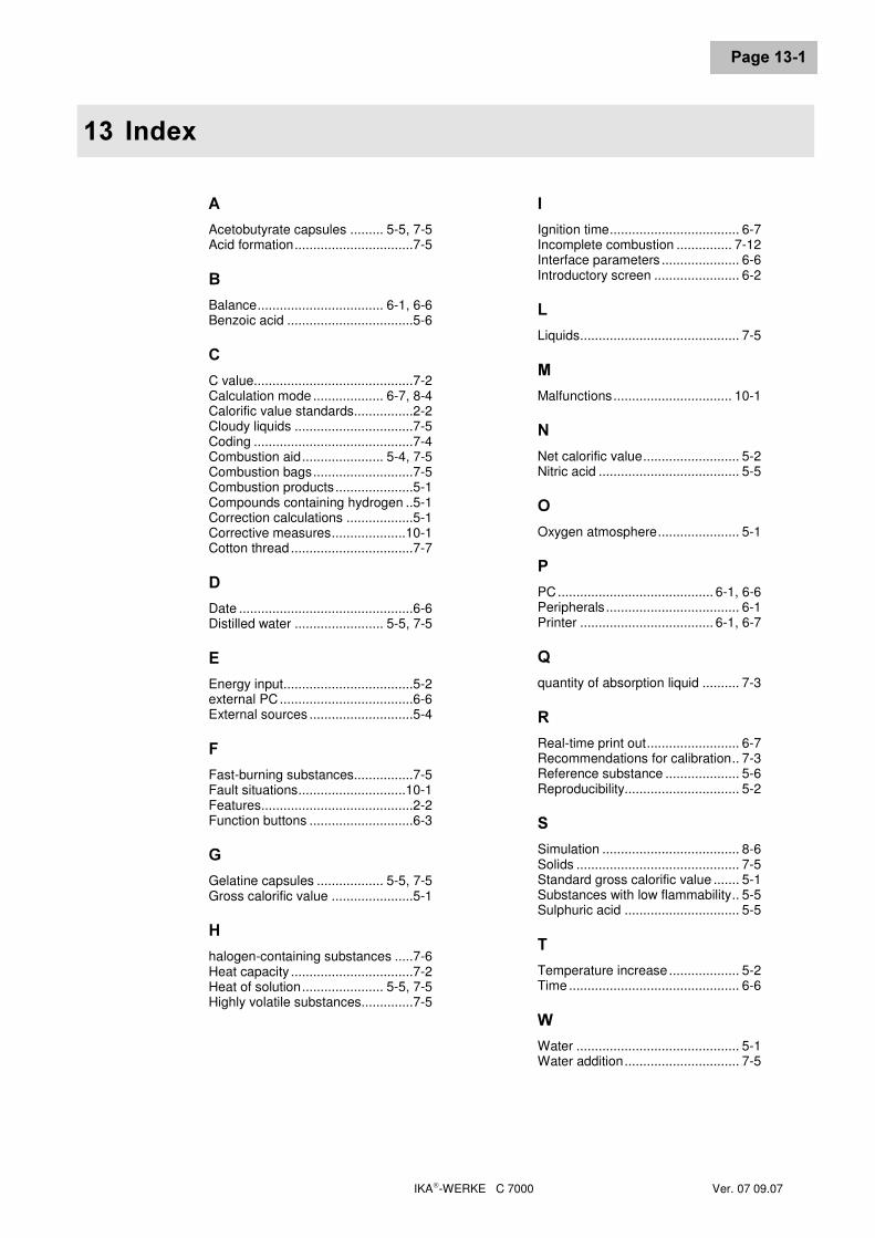
IKA-WERKE C 7000 Ver. 07 09.07
3DJH�����
��� ,QGH[
$Acetobutyrate capsules ......... 5-5, 7-5Acid formation................................7-5
%Balance.................................. 6-1, 6-6Benzoic acid ..................................5-6
&C value...........................................7-2Calculation mode ................... 6-7, 8-4Calorific value standards................2-2Cloudy liquids ................................7-5Coding ...........................................7-4Combustion aid...................... 5-4, 7-5Combustion bags...........................7-5Combustion products.....................5-1Compounds containing hydrogen ..5-1Correction calculations ..................5-1Corrective measures....................10-1Cotton thread .................................7-7
'Date ...............................................6-6Distilled water ........................ 5-5, 7-5
(Energy input...................................5-2external PC....................................6-6External sources ............................5-4
)Fast-burning substances................7-5Fault situations.............................10-1Features.........................................2-2Function buttons ............................6-3
*Gelatine capsules .................. 5-5, 7-5Gross calorific value ......................5-1
+halogen-containing substances .....7-6Heat capacity .................................7-2Heat of solution...................... 5-5, 7-5Highly volatile substances..............7-5
,Ignition time................................... 6-7Incomplete combustion ............... 7-12Interface parameters ..................... 6-6Introductory screen ....................... 6-2
/Liquids........................................... 7-5
0Malfunctions................................ 10-1
1Net calorific value.......................... 5-2Nitric acid ...................................... 5-5
2Oxygen atmosphere...................... 5-1
3PC.......................................... 6-1, 6-6Peripherals.................................... 6-1Printer .................................... 6-1, 6-7
4quantity of absorption liquid .......... 7-3
5Real-time print out......................... 6-7Recommendations for calibration.. 7-3Reference substance .................... 5-6Reproducibility............................... 5-2
6Simulation ..................................... 8-6Solids ............................................ 7-5Standard gross calorific value ....... 5-1Substances with low flammability.. 5-5Sulphuric acid ............................... 5-5
7Temperature increase ................... 5-2Time .............................................. 6-6
:Water ............................................ 5-1Water addition............................... 7-5

IKA-WERKE C 7000 Ver. 07 09.07