Embed Size (px)
Citation preview
DGPF Tagungsband 24 / 2015
190
Camera Based 3D Mine-Shaft Inspection System
JÜRGEN WOHLFEIL1, VOLKER SPRECKELS2, BERNHARD STRACKENBROCK1, ANDREAS SCHLIENKAMP2 & ANDRÉ CHOINOWSKI1
Zusammenfassung: In diesem Beitrag wird die Entwicklung eines optischen 3D-Schacht-Inspektionssystems für Wasserhaltungsschächte im deutschen Ruhrgebiet beschrieben, die Entwicklung erfolgt im Rahmen des Forschungsprojektes „ABSMon“ der RAG Aktiengesellschaft (RAG). Im Steinkohlenfinanzierungsgesetz vom 20.12.2007 (SteinkohleFinG) wurde das Ende des deutschen Steinkohlenbergbaus für Ende 2018 beschlossen. Der Bergbau begann vor etwa drei Jahrhunderten oberflächennah im Süden des Ruhrgebietes und findet derzeit im nördlichen Ruhrgebiet in einer Teufe von bis zu 1.500 Metern statt, wo Pumpmaßnahmen die aktiven Abbaubereiche trocken halten. Nach Beendigung der Abbautätigkeiten wird eine Wasserhaltung den Grubenwasserspiegel auf Dauer kontrolliert auf behördlich vorgegebenen Niveaus halten. Um diese tiefen Wasserhaltungsschächte dauerhaft betreiben und kontrollieren zu können, ist ein mobiles, kabelgeführtes Inspektionssystem nötig. Zurzeit stehen nur Laserscanner-systeme zur Verfügung, benötigt werden aber auch optische Systeme, die eine Inspektion während der Messkampagne mit 3D-Darstellungen und 3D-Auswertungen erlauben. Es wird ein Verfahren vorgestellt, das kamerabasiert hoch aufgelöste und texturierte 3D-Modelle von Schächten und Stollen zum Zwecke der Inspektion solcher Anlagen generiert. Abstract: This paper describes the development of an Optical 3D Shaft Inspection System needed for the survey and monitoring of Water Handling Shafts in the German Ruhrgebiet. The development is part of the RAG R&D project “ABSMon”. The end of the German hard coal mining at the end of 2018 has been determined with the Steinkohlefinanzierungsgesetz (SteinkohleFinG) from 2007-12-20. About three hundred years before now the near surface hard coal mining began in the southern Ruhr Area and in our days advanced to the northern Ruhr Area with mining depth of around -1.500 meters. The mine workings are kept dry by mine water pumping. When the active mining activities will have finished a controlled Water Handling will raise and keep the mine water to levels predetermined by the Mining Authorities. A monitoring with a mobile wireline shaft survey system is needed to run the Water Handling Shafts for an enduring Water Management. At the moment only laser scanner systems are available, but also optical systems are needed to enable the near real-time inspection with 3D presentation and 3D examination during the measurement campaign. An approach is presented that uses a camera to generate high resolution and textured 3D models of mining shafts and tunnels for inspection purposes.
1 German Aerospace Center (DLR), Institute of Optical Sensor Systems, Dpt. Information Processing of
Optical Systems, Rutherfordstr. 2, 12489 Berlin; E-Mail: [juergen.wohlfeil, bernhard.strackenbrock, andre.choinowski]@dIr.de
2 RAG Aktiengesellschaft, Shamrockring 1, 44623 Herne; E-Mail: [volker.spreckels, andreas.schlienkamp]@rag.de
DGPF Tagungsband 24 / 2015
191
1 Introduction
The end of the German hard coal mining at the end of the year 2018 has been determined in the year 2007 with the Steinkohlefinanzierungsgesetz (SteinkohleFinG) from 2007-12-20. About three hundred years before now the near surface hard coal mining began in the southern Ruhr Area and in our days advanced to the northern Ruhr Area with mining depth of around -1.500 meters. Today the mine workings are kept dry by mine water pumping of about 80 million cubic meter per year. When the active mining activities will have finished a controlled Water Handling will allow to raise and keep the highly mineralized saline mine water away from groundwater reservoirs to levels predetermined by the Mining Authorities for an eternal Water Balancing. For the monitoring of shafts for active mining a diversity of survey and monitoring methods are in practice like standard engineering survey or several very special methods operating with thermal imaging, engineering seismic, ultrasonic and acoustic equipment, geo-electric and gravimetric measurements as well as radar technology (FISCHER 2006). But all these methods are cage-based shaft-survey systems and depend on the availability of the shaft infrastructure for active mining like mine headframe, haulage engine, winding rope, pit cage (hoisting cage) and shaft guidance gliding rails. All works are performed from inside or outside the pit cage. According to health & safety at work reasons this has to be taken into account if the works take place in an intake air shaft or a more gaseous uptake air shaft. Therefore explosion-proof (ex-proof) equipment is needed. Current and future Water Handling Stations will no longer have access to this expensive high-maintenance infrastructure and only wireline shaft inspection survey systems can be used for the future shaft-monitoring. The mine shafts with diameters of about 7 meters traverse diverse geological formations and due to rock pressure different materials have been used for the shaft construction like tubbing-segments or brickworks in coal-bearing formations. Latest planning instead mentions the use of immersion pumps through pipeworks, embedded with concrete into the existing shafts. These pipeworks shall have diameters of about 1.5 meters and for this reason an optical 3D camera based inspection system needs to have an operating range from about 0,5 meter to about 10 to 15 meter. The needed accuracy has to be better than 1 cm to be able to detect deformation or cracks at an early stage to prevent serious damages. At the moment two kinds of laser scanner based inspection systems are at use for RAG’s current shaft inspections, both systems are owned by the company DMT located in Essen, Germany (see fig. 1).
- a cage-based shaft-survey system (TANDEM) with 2 ex-proof Z+F IMAGER 5006i (BENECKE & CAIN 2013)
- an ex-proof wireline shaft-survey system (PROFILER) (BENECKE 2014)
Since many years RAG has experience working with 2.5-D-data and 3D point clouds in the fields of aerial (GREIWE et al. 2014) and terrestrial photogrammetry (SCHLIENKAMP et al. 2014) but not in this special field of engineering survey. So this special 3D Camera Based Mine Shaft Inspection System is developed within the RAG R&D project ABSMon and it is planned as an add-on module adapted to DMT’s PROFILER system using the already available mobile infrastructure. Within the last two years a close cooperation between DLR and DMT has taken
DGPF Tagungsband 24 / 2015
192
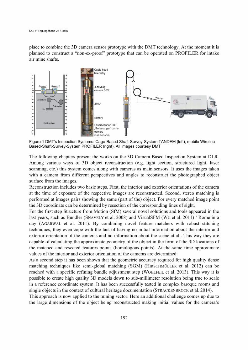
place to combine the 3D camera sensor prototype with the DMT technology. At the moment it is planned to construct a “non-ex-proof” prototype that can be operated on PROFILER for intake air mine shafts.
Figure 1 DMT’s Inspection Systems: Cage-Based Shaft-Survey-System TANDEM (left), mobile Wireline-Based-Shaft-Survey-System PROFILER (right). All images courtesy DMT
The following chapters present the works on the 3D Camera Based Inspection System at DLR. Among various ways of 3D object reconstruction (e.g. light section, structured light, laser scanning, etc.) this system comes along with cameras as main sensors. It uses the images taken with a camera from different perspectives and angles to reconstruct the photographed object surface from the images. Reconstruction includes two basic steps. First, the interior and exterior orientations of the camera at the time of exposure of the respective images are reconstructed. Second, stereo matching is performed at images pairs showing the same (part of the) object. For every matched image point the 3D coordinate can be determined by resection of the corresponding lines of sight. For the first step Structure from Motion (SfM) several novel solutions and tools appeared in the last years, such as Bundler (SNAVELY et al. 2008) and VisualSFM (WU et al. 2011) / Rome in a day (AGARWAL et al. 2011). By combining novel feature matchers with robust stitching techniques, they even cope with the fact of having no initial information about the interior and exterior orientation of the cameras and no information about the scene at all. This way they are capable of calculating the approximate geometry of the object in the form of the 3D locations of the matched and resected features points (homologous points). At the same time approximate values of the interior and exterior orientation of the cameras are determined. As a second step it has been shown that the geometric accuracy required for high quality dense matching techniques like semi-global matching (SGM) (HIRSCHMÜLLER et al. 2012) can be reached with a specific refining bundle adjustment step (WOHLFEIL et al. 2013). This way it is possible to create high quality 3D models down to sub-millimeter resolution being true to scale in a reference coordinate system. It has been successfully tested in complex baroque rooms and single objects in the context of cultural heritage documentation (STRACKENBROCK et al. 2014). This approach is now applied to the mining sector. Here an additional challenge comes up due to the large dimensions of the object being reconstructed making initial values for the camera’s
DGPF Tagungsband 24 / 2015
193
exterior orientations mandatory. In a previous approach the DLR’s integrated navigation system (IPS) was used to obtain initial values for the bundle adjustment (WOHLFEIL et al. 2014). In this paper an odometer designed for DMT’s cage-based shaft-survey system is used to obtain these initial values.
2 3D Reconstruction Approach
To reconstruct a 3D object its surfaces have to be scanned with many images taken with high overlap and from different perspectives. All these images must also be well connected with each other via homologous points (corresponding points visible in two or more images). For compact objects this leads to good reconstruction results. In scenarios with objects of a very large extent in -at least- one direction (like 3D reconstruction of tunnels, mining shafts or large buildings with a complex floor plan) there are two issues that have to be solved: The first problem is the long extent of such objects. Local images are directly connected via homologous points, but images of remote parts of the object are only connected indirectly via homologous points in intermediate images. The accuracy of the relative orientation of two overlapping images is limited by the accuracy of the homologous points connecting them. If not directly connected, the relative orientation of an image at one end of the tunnel respective to an image at the other end of the tunnel is the error sum of relative orientations between the intermediate images on the long chain of images between them. At large objects these errors quickly sum up to critical values. The second problem is the high number of images that is necessary to accurately model such a large object. If no information of the images’ exterior orientation is given, every image has to be compared with every other image in order to find overlapping images and their relative orientations. The computational effort of this processing step quickly exceeds time and hardware constraints if dealing with several thousands of images. This problem is not only related to scenarios of tunnels, mining shafts and large buildings, but to large objects in general that need to be reconstructed with high resolution and hence require a very high number of images. One approach to solve these two major problems was the usage of the DLR’s integrated navigation system (IPS) to obtain initial values for the bundle adjustment (WOHLFEIL et al. 2014). In this paper an odometer is used to obtain these initial values. This odometer was developed by the DMT and constructed especially for the measurement of depth in the context of mining. It can be used for the pit cage system as well as for the mobile wireline system and currently provides the most accurate measurements over long distances. Assuming a vertical descent of the system, the initial values of the cameras exterior orientation can be obtained by just assuming the horizontal translation of the camera (x and y axis) being zero and using the odometer values as shift along the z axis. Of course it is essential that the capture of images and the odometer measurements are precisely time synchronized. In the following section it is explained how this was ensured for the test. Given the approximate exterior orientation from the odometer, most of the possible image pairs can be skipped from feature matching after a quick evaluation of the position and viewing angle of the two images. Only if both images have a similar viewing angle to the same object space limited by the field of view of each image then a full comparison of the images’ features has to be performed, leading to homologous points. The homologous points are required for the refining bundle adjustment step optimizing the exterior orientation to meet the requirements of SGM as presented in (WOHFEIL et al. 2013). If
DGPF Tagungsband 24 / 2015
194
available, additional control points can be included in the bundle adjustment to align the model to an existing coordinate system or to further stabilize the absolute scale of the resulting model. But another reason for the refining bundle adjustment is the need of a very precise knowledge about the relative orientation and the interior orientation of every pair of images used for dense matching. This is needed for an accurate stereo rectification of the images being matched. It significantly improves the quality of the dense matching results if known with subpixel accuracy. For dense matching SGM (HIRSCHMÜLLER, 2008) was used as it turned out to achieve better results in many cases than other stereo matching methods (HIRSCHMÜLLER et al. 2010) and other technologies, e.g. laser scanning (GEHRKE et al. 2010). Moreover, stereo matching can be performed more economically than its technological alternatives, as it does not require additional sensors. Despite of its relatively high computational complexity the computation time can be handled very well by parallelization and/or optimization for special hardware like graphic cards (ERNST et al. 2008) and FPGAs (HIRSCHMÜLLER et al. 2012). The goal of 3D scene reconstruction is to generate a complete and textured mesh or a point cloud with color information, which describes the surface of the objects in the scene down to pixel scale. One method is the generation of a partial mesh from the dense matching results of each image. Then the partial meshes are combined to one large mesh of the whole scene. Optionally the mesh can be smoothed, reduced and manually cleaned. For these steps the software of David laser scanner system (BAUER 2013) proved to give the best results. The model is then textured by the same images which were used for dense matching. Larger objects with several hundreds or thousands of images have to be split up into several parts before the scene reconstruction steps can be performed. Finally, the scene (or all its parts) can be loaded in commercial tools for further processing and analyses.
3 Test of the System
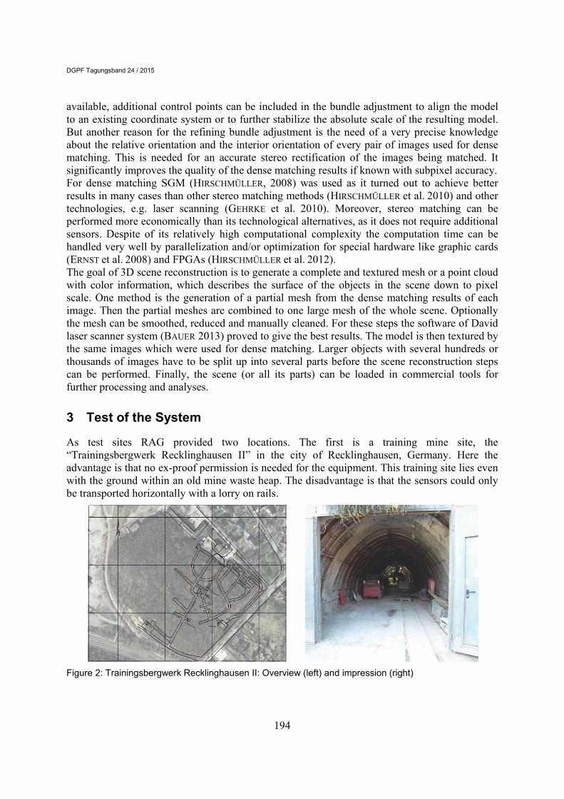
As test sites RAG provided two locations. The first is a training mine site, the “Trainingsbergwerk Recklinghausen II” in the city of Recklinghausen, Germany. Here the advantage is that no ex-proof permission is needed for the equipment. This training site lies even with the ground within an old mine waste heap. The disadvantage is that the sensors could only be transported horizontally with a lorry on rails.
Figure 2: Trainingsbergwerk Recklinghausen II: Overview (left) and impression (right)
DGPF Tagungsband 24 / 2015
195
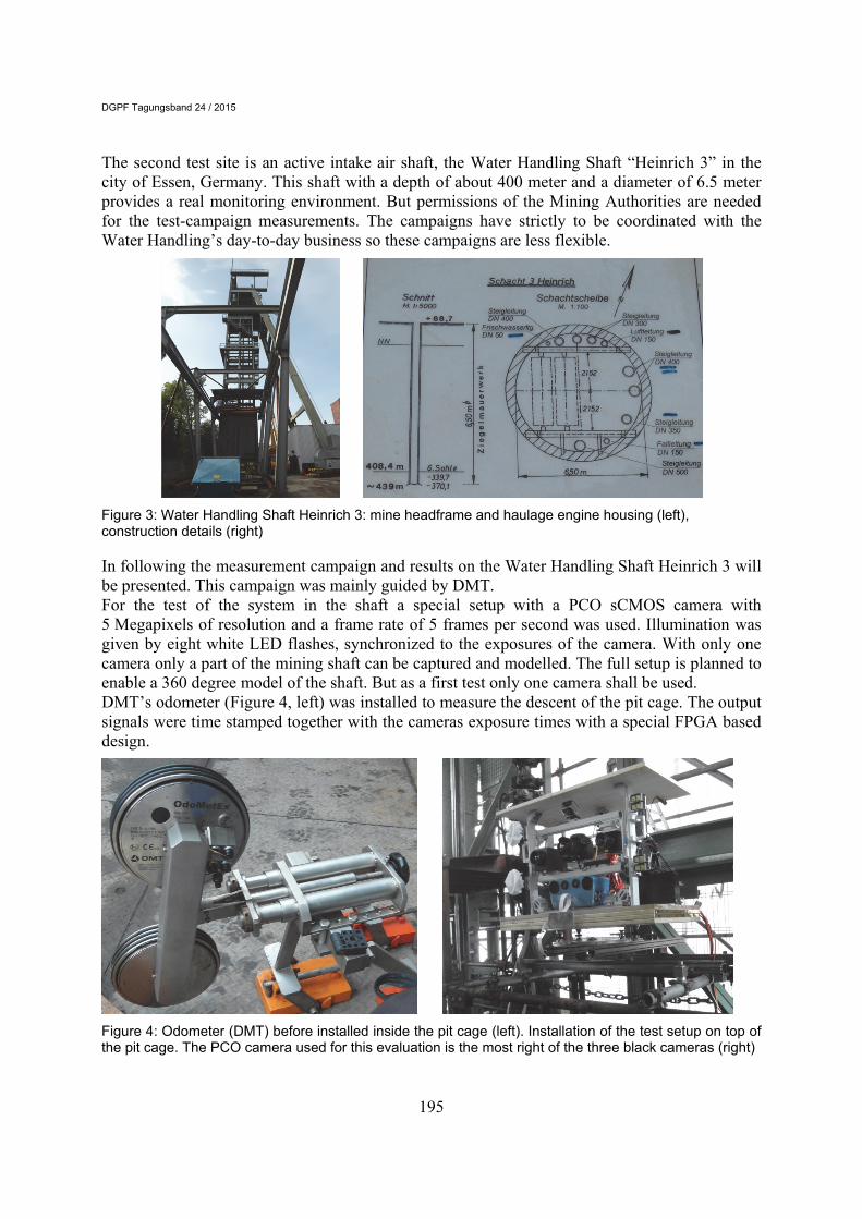
The second test site is an active intake air shaft, the Water Handling Shaft “Heinrich 3” in the city of Essen, Germany. This shaft with a depth of about 400 meter and a diameter of 6.5 meter provides a real monitoring environment. But permissions of the Mining Authorities are needed for the test-campaign measurements. The campaigns have strictly to be coordinated with the Water Handling’s day-to-day business so these campaigns are less flexible.
Figure 3: Water Handling Shaft Heinrich 3: mine headframe and haulage engine housing (left), construction details (right)
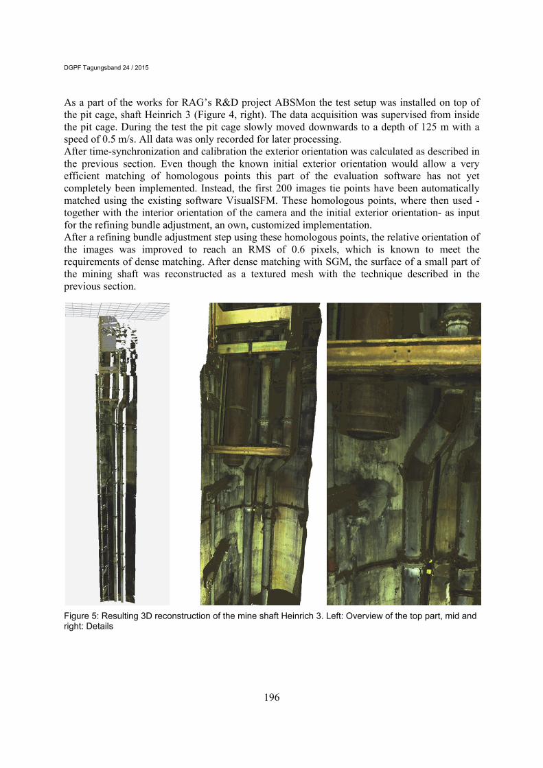
In following the measurement campaign and results on the Water Handling Shaft Heinrich 3 will be presented. This campaign was mainly guided by DMT. For the test of the system in the shaft a special setup with a PCO sCMOS camera with 5 Megapixels of resolution and a frame rate of 5 frames per second was used. Illumination was given by eight white LED flashes, synchronized to the exposures of the camera. With only one camera only a part of the mining shaft can be captured and modelled. The full setup is planned to enable a 360 degree model of the shaft. But as a first test only one camera shall be used. DMT’s odometer (Figure 4, left) was installed to measure the descent of the pit cage. The output signals were time stamped together with the cameras exposure times with a special FPGA based design.
Figure 4: Odometer (DMT) before installed inside the pit cage (left). Installation of the test setup on top of the pit cage. The PCO camera used for this evaluation is the most right of the three black cameras (right)
DGPF Tagungsband 24 / 2015
196
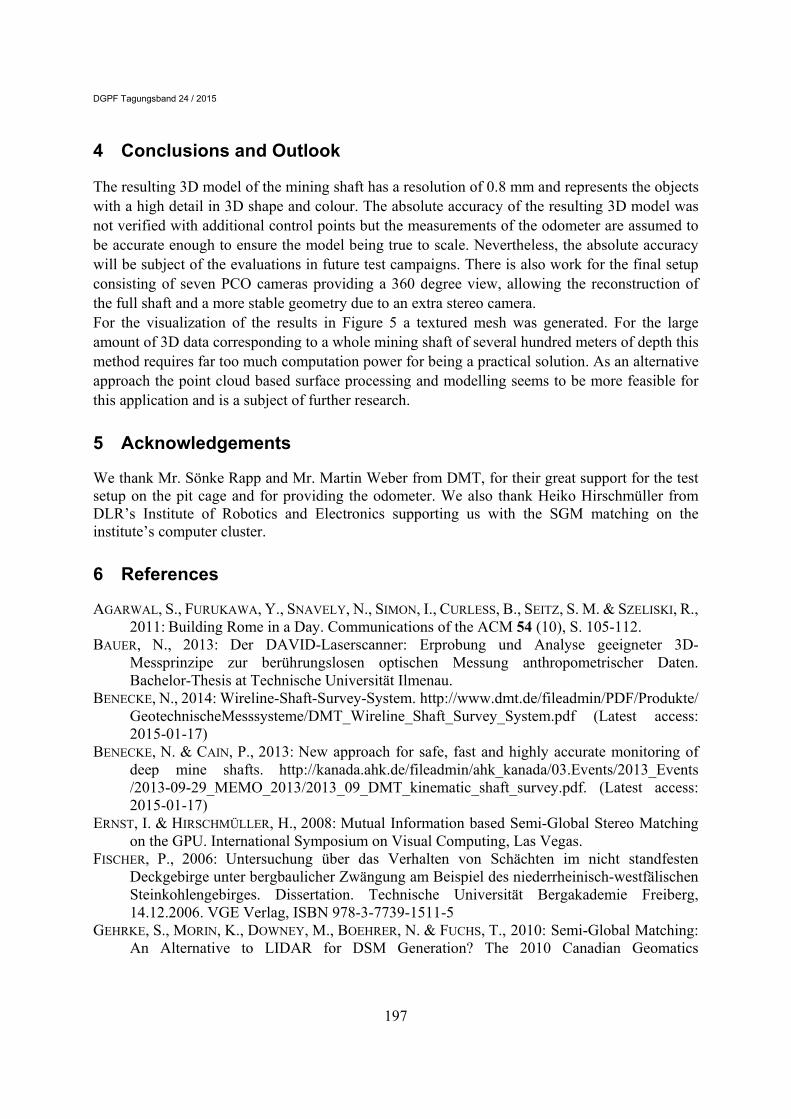
As a part of the works for RAG’s R&D project ABSMon the test setup was installed on top of the pit cage, shaft Heinrich 3 (Figure 4, right). The data acquisition was supervised from inside the pit cage. During the test the pit cage slowly moved downwards to a depth of 125 m with a speed of 0.5 m/s. All data was only recorded for later processing. After time-synchronization and calibration the exterior orientation was calculated as described in the previous section. Even though the known initial exterior orientation would allow a very efficient matching of homologous points this part of the evaluation software has not yet completely been implemented. Instead, the first 200 images tie points have been automatically matched using the existing software VisualSFM. These homologous points, where then used -together with the interior orientation of the camera and the initial exterior orientation- as input for the refining bundle adjustment, an own, customized implementation. After a refining bundle adjustment step using these homologous points, the relative orientation of the images was improved to reach an RMS of 0.6 pixels, which is known to meet the requirements of dense matching. After dense matching with SGM, the surface of a small part of the mining shaft was reconstructed as a textured mesh with the technique described in the previous section.
Figure 5: Resulting 3D reconstruction of the mine shaft Heinrich 3. Left: Overview of the top part, mid and right: Details
DGPF Tagungsband 24 / 2015
197
4 Conclusions and Outlook
The resulting 3D model of the mining shaft has a resolution of 0.8 mm and represents the objects with a high detail in 3D shape and colour. The absolute accuracy of the resulting 3D model was not verified with additional control points but the measurements of the odometer are assumed to be accurate enough to ensure the model being true to scale. Nevertheless, the absolute accuracy will be subject of the evaluations in future test campaigns. There is also work for the final setup consisting of seven PCO cameras providing a 360 degree view, allowing the reconstruction of the full shaft and a more stable geometry due to an extra stereo camera. For the visualization of the results in Figure 5 a textured mesh was generated. For the large amount of 3D data corresponding to a whole mining shaft of several hundred meters of depth this method requires far too much computation power for being a practical solution. As an alternative approach the point cloud based surface processing and modelling seems to be more feasible for this application and is a subject of further research.
5 Acknowledgements
We thank Mr. Sönke Rapp and Mr. Martin Weber from DMT, for their great support for the test setup on the pit cage and for providing the odometer. We also thank Heiko Hirschmüller from DLR’s Institute of Robotics and Electronics supporting us with the SGM matching on the institute’s computer cluster.
6 References
AGARWAL, S., FURUKAWA, Y., SNAVELY, N., SIMON, I., CURLESS, B., SEITZ, S. M. & SZELISKI, R., 2011: Building Rome in a Day. Communications of the ACM 54 (10), S. 105-112.
BAUER, N., 2013: Der DAVID-Laserscanner: Erprobung und Analyse geeigneter 3D-Messprinzipe zur berührungslosen optischen Messung anthropometrischer Daten. Bachelor-Thesis at Technische Universität Ilmenau.
BENECKE, N., 2014: Wireline-Shaft-Survey-System. http://www.dmt.de/fileadmin/PDF/Produkte/ GeotechnischeMesssysteme/DMT_Wireline_Shaft_Survey_System.pdf (Latest access: 2015-01-17)
BENECKE, N. & CAIN, P., 2013: New approach for safe, fast and highly accurate monitoring of deep mine shafts. http://kanada.ahk.de/fileadmin/ahk_kanada/03.Events/2013_Events /2013-09-29_MEMO_2013/2013_09_DMT_kinematic_shaft_survey.pdf. (Latest access: 2015-01-17)
ERNST, I. & HIRSCHMÜLLER, H., 2008: Mutual Information based Semi-Global Stereo Matching on the GPU. International Symposium on Visual Computing, Las Vegas.
FISCHER, P., 2006: Untersuchung über das Verhalten von Schächten im nicht standfesten Deckgebirge unter bergbaulicher Zwängung am Beispiel des niederrheinisch-westfälischen Steinkohlengebirges. Dissertation. Technische Universität Bergakademie Freiberg, 14.12.2006. VGE Verlag, ISBN 978-3-7739-1511-5
GEHRKE, S., MORIN, K., DOWNEY, M., BOEHRER, N. & FUCHS, T., 2010: Semi-Global Matching: An Alternative to LIDAR for DSM Generation? The 2010 Canadian Geomatics
DGPF Tagungsband 24 / 2015
198
Conference and Symposium of Commission I, ISPRS Convergence in Geomatics – Shaping Canada's Competitive Landscape.
GREIWE, A., GEHRKE, R., SPRECKELS, V. & SCHLIENKAMP, A., 2014: Ableitung eines Geländemodells aus multispektralen UAS-Bilddaten. Publikationen der Deutschen Gesellschaft für Photogrammetrie, Fernerkundung und Geoinformation e.V., Band 23, Seyfert, E., Gülch, E., Heipke, C., Schiewe, J. & Sester, M. (Hrsg.), Tagungsband auf CD-ROM, Beitrag 256.
GRIEßBACH, D., BAUMBACH, D. & ZUEV, S., 2014: Stereo vision aided inertial navigation for unknown indoor and outdoor environments. IPIN International Conference on Indoor Positioning and Indoor Navigation
HIRSCHMÜLLER, H., 2008: Stereo Processing by Semiglobal Matching and Mutual Information. IEEE Transactions on Pattern Analysis and Machine Intelligence 30 (2), S. 328-341.
HIRSCHMÜLLER, H. & BUCHER, T., 2010: Evaluation of Digital Surface Models by Semi-Global Matching. Publikationen der Deutschen Gesellschaft für Photogrammetrie, Fernerkundung und Geoinformation e.V., Band 19, Seyfert, E., (Hrsg.), S. 571-580.
HIRSCHMÜLLER, H., BUDER, M. & ERNST, I., 2012: Memory Efficient Semi-Global Matching. ISPRS Annals of the Photogrammetry, Remote Sensing and Spatial Information Sciences 3, S. 371-376.
SCHLIENKAMP, A., FISCHER, P., SPRECKELS, V. & VOSEN, P., 2014: Mehrstufiges Konzept der RAG zur Aufnahme, Analyse und Visualisierung von Industriestandorten aus 3D-Punktwolken. 15. Geokinematischer Tag, May 15.-16. 2014, Freiberg, Germany, Schriftenreihe des Institutes für Markscheidewesen und Geodäsie an der TU Bergakademie Freiberg, Heft 2014–1, S. 264-276.
SNAVELY, N., SEITZ, S. M. & SZELISKI, R., 2008: Modeling the World from Internet Photo Collections. International Journal of Computer Vision 80 (2), S. 189-210.
STEINKOHLEFING. "Steinkohlefinanzierungsgesetz vom 20. Dezember 2007 (BGBl. I S. 3086), das durch Artikel 1 des Gesetzes vom 11. Juli 2011 (BGBl. I S. 1344) geändert worden ist". http://www.gesetze-im-internet.de/bundesrecht/steinkohlefing/gesamt.pdf. (Latest access: 2015-01-17)
STRACKENBROCK, B., HIRZINGER, G. & WOHLFEIL, J., 2014: Multi-Scale / Multi-Sensor 3D-Dokumentation und 3D-Visualisierung höfischer Prunkräume. To be published in the proceedings of EVA conference on Electronic Media and Art, Culture, History held in Berlin, Germany, November 5th-7th 2014.
WOHLFEIL, J., 2010: Completely optical orientation determination for an unstabilized aerial three-line camera. Proceedings of SPIE Sensors, Systems, and Next-Generation Satellites XIV, 7826.
WOHLFEIL, J., 2012: Determining fast orientation changes of multi-spectral line cameras from the primary images. ISPRS Journal of Photogrammetry and Remote Sensing 67, S. 45-51.
WOHLFEIL, J., STRACKENBROCK, B. & KOSSYK, I. 2013: Automated high resolution 3D reconstruction of cultural heritage using multi-scale sensor systems and semi-global matching. International Archives of the Photogrammetry, Remote Sensing and Spatial Information Sciences, Volume XL-4/W4, 2013, S. 37-43.
WOHLFEIL, J., STRACKENBROCK, B. & CHOINOWSKI, A., 2014: Camera Based 3D Object Reconstruction. Proc. of 3D-NordOst 17, S. 53-62.
WU, C., AGARWAL, S., CURLESS, B. & SEITZ, S. M., 2011: Multicore Bundle Adjustment. IEEE Conference on Computer Vision and Pattern Recognition (CVPR), S. 3057-3064.