Embed Size (px)
Citation preview

1
ZV
L414
.04
Mod
. 09-
04-2
004
REMARQUE Page 20CARACTÉRISTIQUES TECHNIQUES Page 20MISE EN PLACE DE L’INTERFACE Page 21MISE EN PLACE DU CLAVIER Page 22PROCÉDÉ DE PROGRAMMATION Page 23-24MODE DE FONCTIONNEMENT Page 25-27NOTES Page 28
ANWEISUNGEN Seite 29TECHNISCHE DATEN Seite 29SCHNITTSTELLEN-INSTALLATION Seite 30TASTATUR-INSTALLATION Seite 31PROGRAMMIERVERFAHREN Seite 32-33BETRIEBSWEISE Seite 34-36ANMERKUNGEN Seite 37
ADVERTENCIAS Página 38CARACTERISTICAS TECNICAS Página 38INSTALACIÓN DE LA INTERFAZ Página 39INSTALACIÓN DEL TECLADO Página 40PROCEDIMIENTO PARA LA PROGRAMACIÓN Página 41-42MODALIDAD DE FUNCIONAMIENTO Página 43-45NOTAS Página 46
FRANÇAIS
DEUTSCH
ESPAÑOL
DKS 250ZVL414.04This product has been tried and tested in the manufacturer's laboratory, during the installation of the product follow the supplied indications carefully.
CARDIN ELETTRONICA spa Via Raffaello, 36- 31020 San Vendemiano (TV) ItalyTel: +39/0438.404011-401818Fax: +39/0438.401831email (Italy): [email protected] (Europe): [email protected]: www.cardin.it
TASTIERA A CODICE NUMERICO
NUMERICAL CODE KEYBOARD
CLAVIER À CODE NUMÉRIQUE
TASTATUR MIT NUMERISCHEM CODE
TECLADO DE CÓDIGO NUMÉRICO
IMPORTANT REMARKS Page 11TECHNICAL SPECIFICATIONS Page 11INTERFACE INSTALLATION Page 12KEYBOARD INSTALLATION Page 13PROGRAMMING PROCEDURE Page 14-15OPERATING MODE Page 16-18NOTES Page 19
ENGLISH
ITALIANOAVVERTENZE Pagina 2CARATTERISTICHE TECNICHE Pagina 2 INSTALLAZIONE INTERFACCIA Pagina 3INSTALLAZIONE TASTIERA Pagina 4PROCEDURA DI PROGRAMMAZIONE Pagina 5-6MODALITÀ DI FUNZIONAMENTO Pagina 7-9NOTE Pagina 10

2
Prima di dar inizio all’installazione leggere attentamente il presente fascicolo. In particolare, prendere visione dei dispositivi di sicurezza previsti dal prodotto per utilizzarli con la massima efficacia. Prima di procedere con la programmazione leggere attentamente le "NOTE" a pag. 10. L’utilizzo dei prodotti e la loro destinazione ad usi diversi da quelli previsti e/o consigliati, non è stato sperimentato dal costruttore, pertanto i lavori eseguiti sono sotto la completa responsabilità dell’installatore.Il presente manuale si rivolge a persone abilitate all'installazione di "APPARECCHI UTILIZZATORI DI ENERGIA ELETTRICA" e richiede una buona conoscenza della tecnica, esercitata in forma professionale. Il costruttore declina ogni responsabilità per eventuali danni provocati dalla mancata osservanza nell'installazione delle norme di sicurezza attualmente in vigore.
Descrizione
Il sistema si compone di due elementi collegati fra loro via filo: - DKS250T tastiera numerica da esterno, - DKS250R interfaccia per collegamento seriale.
La tastiera è costituita da una struttura metallica in zama, antiscasso, con verniciatura ad alta resistenza e tasti cromati antiusura. Di facile installazione è dotata di un grado di protezione IP57 e di un sistema di fissaggio antiscasso con vite e chiave speciali.Dotata inoltre di:- LED rosso segnalazione - LED verde segnalazione- 10 tasti numerici (0-9)- un tasto di conferma *- un tasto di annullamento operazione #- 4 funzioni di canale (A, B, C, D) - buzzer segnalazione sonora.
L’interfaccia collocata in un contenitore da interno IP20 si collega alla tastiera con cavo telefonico (o equivalente) a due conduttori Ø 0,6 mm, lunghezza massima 150 m dotata di tasto di programmazione e due LED L1 verde L2 rosso di segna-lazione visiva.
Possibilità di impiego
Il sistema DKS250 permette l'attuazione via filo di apparecchiature elettriche ed elettroniche, fornendo la massima sicurezza e trovando il suo miglior impiego nel comando di porte e portoni motorizzati.
Numero di codici utente memorizzabili (max 6 cifre ciascuno) ............................................................................................... 250Numero di combinazioni di codici disponibili ..................................................................................................................1 milione
CARATTERISTICHE TECNICHE
Alimentazione .............................................................................................12/24Vac-dc
Assorbimento:
Tastiera ................................................................................................................. 6mA
Interfaccia con tastiera ...................................................................................... 31mA
Interfaccia con tastiera e un canale attivo ........................................................ 54mA
Max potenza commutabile del relé con carico resistivo (escluse lampadine):
carico in ac/dc ............................................................................................60VA/24W
Tensione massima ....................................................................................... 30Vac-dc
Ritardo all'attivazione del relé .................................................................... 80-100ms
Temperatura di esercizio tastiera/interfaccia ...........................................-10° …+55°C
ITALIANO AVVERTENZE ITALIANO
(dimensioni d'ingombro)
21-05-97
DM0275 Description :
Product Code :
Date :
Drawing number :
P.J.Heath
CARDIN ELETTRONICA S.p.A - 31020 San Vendemiano (TV) Italy - via Raffaello, 36 Tel: 0438/401818 Fax: 0438/401831
Draft :
All rights reserved. Unauthorised copying or use of the information contained in this document is punishable by law
RXRADO RXRADO
95
25
75
A
1
2
5
8
0
3
6
94
7
*
B
C
D
2672
104
Montaggio Tastiera DKS250T a superfice
DKS250T
28-11-2001
DM0557 Description :
Product Code :
Date :
Drawing number :
P.J.Heath
CARDIN ELETTRONICA S.p.A - 31020 San Vendemiano (TV) Italy - via Raffaello, 36 Tel: 0438/401818 Fax: 0438/401831
Draft :
All rights reserved. Unauthorised copying or use of the information contained in this document is punishable by law
1
Dimensioni d'ingombro
Interfaccia
Tastiera
3
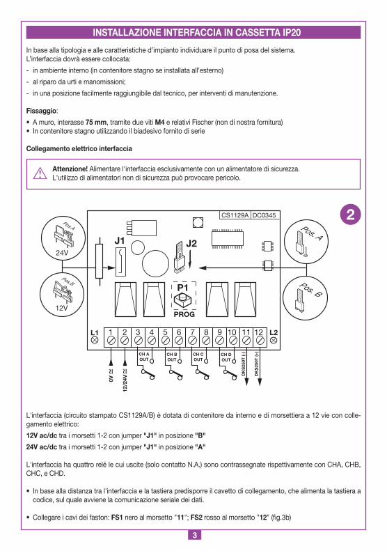
In base alla tipologia e alle caratteristiche d’impianto individuare il punto di posa del sistema.L’interfaccia dovrà essere collocata:
- in ambiente interno (in contenitore stagno se installata all'esterno)
- al riparo da urti e manomissioni;
- in una posizione facilmente raggiungibile dal tecnico, per interventi di manutenzione.
Fissaggio:
• A muro, interasse 75 mm, tramite due viti M4 e relativi Fischer (non di nostra fornitura) • In contenitore stagno utilizzando il biadesivo fornito di serie
Collegamento elettrico interfaccia
Attenzione! Alimentare l'interfaccia esclusivamente con un alimentatore di sicurezza.L'utilizzo di alimentatori non di sicurezza può provocare pericolo.
L'interfaccia (circuito stampato CS1129A/B) è dotata di contenitore da interno e di morsettiera a 12 vie con colle-gamento elettrico:
12V ac/dc tra i morsetti 1-2 con jumper "J1" in posizione "B"
24V ac/dc tra i morsetti 1-2 con jumper "J1" in posizione "A"
L'interfaccia ha quattro relé le cui uscite (solo contatto N.A.) sono contrassegnate rispettivamente con CHA, CHB, CHC, e CHD.
• In base alla distanza tra l'interfaccia e la tastiera predisporre il cavetto di collegamento, che alimenta la tastiera a codice, sul quale avviene la comunicazione seriale dei dati.
• Collegare i cavi dei faston: FS1 nero al morsetto "11"; FS2 rosso al morsetto "12" (fig.3b)
CS1129A DC0345
J2
P1
PROG
24V
12V
Pos.A
Pos.B
J1
12/2
4V0V
1 2 3 4 5 6 7 8 9 10 11 12
CH BOUT
CH AOUT
CH DOUT
CH COUT
DK
S25
0T (-
)
DK
S25
0T (+
)
L1 L2
Interfaccia
DKS250R
28-11-2001
DC0345 Description :
Product Code :
Date :
Drawing number :
P.J.Heath
CARDIN ELETTRONICA S.p.A - 31020 San Vendemiano (TV) Italy - via Raffaello, 36 Tel: 0438/401818 Fax: 0438/401831
Draft :
All rights reserved. Unauthorised copying or use of the information contained in this document is punishable by law
DKS250R
Pos. A
Pos. B
2
INSTALLAZIONE INTERFACCIA IN CASSETTA IP20

4
1) Far passare i cavi di collegamento "1" provenienti dall'interfaccia attraverso il muro.
2) Forare il muro alla distanza indicata in figura 3a (58 mm).
3) Inserire i Fischer "2" forniti con il kit.
4) Bloccare la contropiastra "3" utilizzando le viti "4" fornite con il kit.
5) Collegare i faston dei cavi "1" ai faston della tastiera "5" (fig, 3a-3b): - filo rosso dal tastierino al morsetto 12 del interfaccia - filo nero dal tastierino al morsetto 11 del interfaccia
6) Infine posizionare la tastiera (fig 3b-3c) e bloccarla alla contropiastra utilizzando la vite speciale "S1" e l'apposito attrezzo "K1".
A
1
2
5
8
0
3
6
94
7
*
B
C
D
Montaggio Tastiera DKS250T a superfice
DKS250T
28-11-2001
DM0557 Description :
Product Code :
Date :
Drawing number :
P.J.Heath
CARDIN ELETTRONICA S.p.A - 31020 San Vendemiano (TV) Italy - via Raffaello, 36 Tel: 0438/401818 Fax: 0438/401831
Draft :
All rights reserved. Unauthorised copying or use of the information contained in this document is punishable by law
58 mm
1
2 3
4
5
3a
Montaggio Tastiera DKS250T a superfice
DKS250T
04-03-2002
DM0670 Description :
Product Code :
Date :
Drawing number :
P.J.Heath
CARDIN ELETTRONICA S.p.A - 31020 San Vendemiano (TV) Italy - via Raffaello, 36 Tel: 0438/401818 Fax: 0438/401831
Draft :
All rights reserved. Unauthorised copying or use of the information contained in this document is punishable by law
FS
1 (-) Bl
FS
2 (+) Rd
FASTON
A
1
2
5
8
0
3
6
94
7
*
B
C
D
Montaggio Tastiera DKS250T a superfice
DKS250T
28-11-2001
DM0669 Description :
Product Code :
Date :
Drawing number :
P.J.Heath
CARDIN ELETTRONICA S.p.A - 31020 San Vendemiano (TV) Italy - via Raffaello, 36 Tel: 0438/401818 Fax: 0438/401831
Draft :
All rights reserved. Unauthorised copying or use of the information contained in this document is punishable by law
K1
S1
3b
3c
INSTALLAZIONE TASTIERA ESTERNA IP57
Rd.= Rosso
Bl.= Nero
5
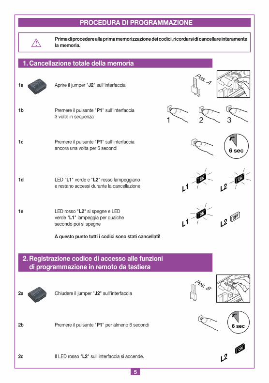
Prima di procedere alla prima memorizzazione dei codici, ricordarsi di cancellare interamente la memoria.
1a Aprire il jumper "J2" sull'interfaccia
1b Premere il pulsante "P1" sull'interfaccia 3 volte in sequenza
1c Premere il pulsante "P1" sull'interfaccia ancora una volta per 6 secondi
1d LED "L1" verde e "L2" rosso lampeggiano e restano accessi durante la cancellazione
1e LED rosso "L2" si spegne e LED verde "L1" lampeggia per qualche secondo poi si spegne
A questo punto tutti i codici sono stati cancellati!
2a Chiudere il jumper "J2" sull'interfaccia
2b Premere il pulsante "P1" per almeno 6 secondi
2c Il LED rosso "L2" sull'interfaccia si accende.
1 2 3
6 sec
L2ON
L1ON
L2OFF
L1ON
1. Cancellazione totale della memoria
PROCEDURA DI PROGRAMMAZIONE
Pos. A
2. Registrazione codice di accesso alle funzioni di programmazione in remoto da tastiera
6 sec
L2ON
Pos. B
6
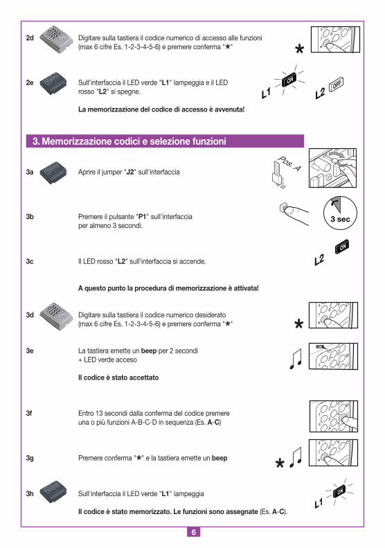
2d Digitare sulla tastiera il codice numerico di accesso alle funzioni (max 6 cifre Es. 1-2-3-4-5-6) e premere conferma "*"
2e Sull'interfaccia il LED verde "L1" lampeggia e il LED rosso "L2" si spegne.
La memorizzazione del codice di accesso è avvenuta!
3a Aprire il jumper "J2" sull'interfaccia
3b Premere il pulsante "P1" sull'interfaccia per almeno 3 secondi.
3c Il LED rosso "L2" sull'interfaccia si accende.
A questo punto la procedura di memorizzazione è attivata!
3d Digitare sulla tastiera il codice numerico desiderato (max 6 cifre Es. 1-2-3-4-5-6) e premere conferma "*"
3e La tastiera emette un beep per 2 secondi + LED verde acceso
Il codice è stato accettato
3f Entro 13 secondi dalla conferma del codice premere una o più funzioni A-B-C-D in sequenza (Es. A-C)
3g Premere conferma "*" e la tastiera emette un beep
3h Sull'interfaccia il LED verde "L1" lampeggia Il codice è stato memorizzato. Le funzioni sono assegnate (Es. A-C).
8
0
94
7
*
D
1
23
6
B
C
ON
A
1
2
5
8
3
6
94
B
C
D
8
0
94
7
*
D
L1ON
*
8
0
94
7
*
D
L1ON
L2OFF
*
*
3. Memorizzazione codici e selezione funzioni
3 sec
L2ON
Pos. A
7
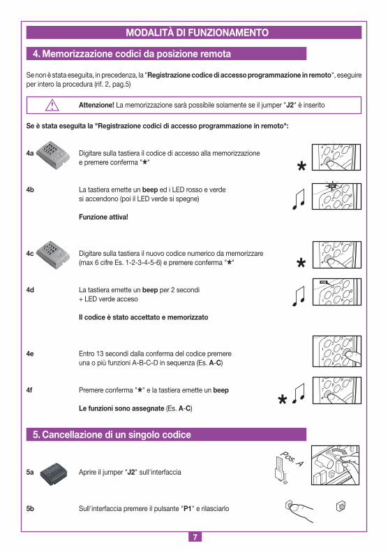
Se non è stata eseguita, in precedenza, la "Registrazione codice di accesso programmazione in remoto", eseguire per intero la procedura (rif. 2, pag.5)
Attenzione! La memorizzazione sarà possibile solamente se il jumper "J2" è inserito
Se è stata eseguita la "Registrazione codici di accesso programmazione in remoto":
4a Digitare sulla tastiera il codice di accesso alla memorizzazione e premere conferma "*"
4b La tastiera emette un beep ed i LED rosso e verde si accendono (poi il LED verde si spegne)
Funzione attiva!
4c Digitare sulla tastiera il nuovo codice numerico da memorizzare (max 6 cifre Es. 1-2-3-4-5-6) e premere conferma "*"
4d La tastiera emette un beep per 2 secondi + LED verde acceso
Il codice è stato accettato e memorizzato
4e Entro 13 secondi dalla conferma del codice premere una o più funzioni A-B-C-D in sequenza (Es. A-C)
4f Premere conferma "*" e la tastiera emette un beep
Le funzioni sono assegnate (Es. A-C)
5a Aprire il jumper "J2" sull'interfaccia
5b Sull'interfaccia premere il pulsante "P1" e rilasciarlo
MODALITÀ DI FUNZIONAMENTO
4. Memorizzazione codici da posizione remota
*
*
8
0
94
7
*
D
8
0
94
7
*
D
1
23
6
B
C
ON
5. Cancellazione di un singolo codice
Pos. A
1
23
6
B
C
ON
A
1
2
5
8
3
6
94
B
C
D
8
0
94
7
*
D
*
8
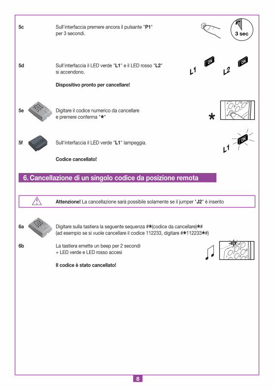
5c Sull'interfaccia premere ancora il pulsante "P1" per 3 secondi.
5d Sull'interfaccia il LED verde "L1" e il LED rosso "L2" si accendono.
Dispositivo pronto per cancellare!
5e Digitare il codice numerico da cancellare e premere conferma "*"
5f Sull'interfaccia il LED verde "L1" lampeggia.
Codice cancellato!
Attenzione! La cancellazione sarà possibile solamente se il jumper "J2" è inserito
6a Digitare sulla tastiera la seguente sequenza #*(codice da cancellare)*# (ad esempio se si vuole cancellare il codice 112233, digitare #*112233*#)
6b La tastiera emette un beep per 2 secondi + LED verde e LED rosso accesi
Il codice è stato cancellato!
3 sec
L2ON
L1ON
L1ON
*8
0
94
7
*
D
6. Cancellazione di un singolo codice da posizione remota
1
23
6
B
C
ON
9
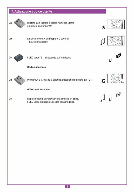
7a Digitare sulla tastiera il codice numerico utente e premere conferma "*"
7b La tastiera emette un beep per 2 secondi + LED verde acceso
7c Il LED verde "L1" si accende sull'interfaccia
Codice accettato!
7d Premere A-B-C o D nella colonna a destra sulla tastiera (Es. "C")
Attivazione avvenuta!
7e Dopo 5 secondi di inattività verrà emesso un beep. Il LED verde si spegne e si esce dalla modalità.
L1ON
*8
0
94
7
*
D
1
23
6
B
C
ON
L1OFF
c1
5
8
6
94
B
C
7. Attivazione codice utente
10
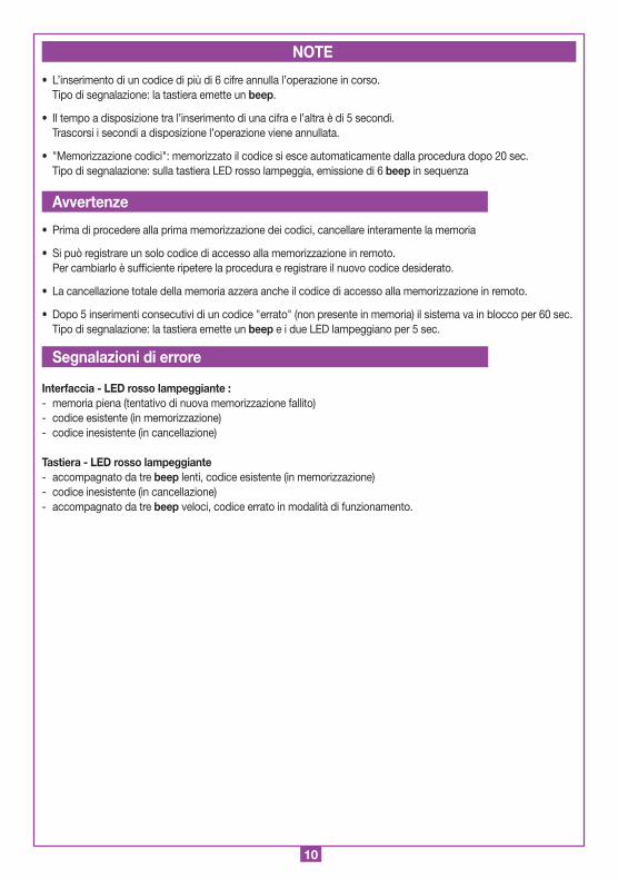
• L’inserimento di un codice di più di 6 cifre annulla l’operazione in corso. Tipo di segnalazione: la tastiera emette un beep.
• Il tempo a disposizione tra l’inserimento di una cifra e l’altra è di 5 secondi. Trascorsi i secondi a disposizione l’operazione viene annullata.
• "Memorizzazione codici": memorizzato il codice si esce automaticamente dalla procedura dopo 20 sec. Tipo di segnalazione: sulla tastiera LED rosso lampeggia, emissione di 6 beep in sequenza
• Prima di procedere alla prima memorizzazione dei codici, cancellare interamente la memoria
• Si può registrare un solo codice di accesso alla memorizzazione in remoto. Per cambiarlo è sufficiente ripetere la procedura e registrare il nuovo codice desiderato.
• La cancellazione totale della memoria azzera anche il codice di accesso alla memorizzazione in remoto.
• Dopo 5 inserimenti consecutivi di un codice "errato" (non presente in memoria) il sistema va in blocco per 60 sec. Tipo di segnalazione: la tastiera emette un beep e i due LED lampeggiano per 5 sec.
Interfaccia - LED rosso lampeggiante :- memoria piena (tentativo di nuova memorizzazione fallito)- codice esistente (in memorizzazione)- codice inesistente (in cancellazione)
Tastiera - LED rosso lampeggiante- accompagnato da tre beep lenti, codice esistente (in memorizzazione)- codice inesistente (in cancellazione)- accompagnato da tre beep veloci, codice errato in modalità di funzionamento.
NOTE
Avvertenze
Segnalazioni di errore

11
ENGLISH REMARKS ENGLISH
Before commencing with the installation of this appliance make sure that you have read the following instructions carefully. In particular familiarise yourself with the safety devices required by the system, only then will you be able to use them to great effect. Before beginning programming read the "NOTES" on page 19 carefully. The use and installation of these appliances must rigorously respect the indications supplied by the manufacturer. The manufacturer accepts no liability for damage caused by, or situations arising from, the improper use of these appliances. These instructions are aimed at professionally qualified "installers of electrical equipment" and must respect the local standards and regulations in force.
Description
The system is made up of two elements connected together via cable: - DKS250T outdoor numerical code keyboard, - DKS250R serial connection interface.
The keyboard consists of an spray painted highly resistant anti-tamper metal case made in zama and chrome anti wear keys. Easy to install the keyboard has a protection grade of IP57 and features an antitamper fastening system which can only be opened using a special tool.It also has the following features:- red signal LED - green signal LED- 10 numerical keys (0-9)- one confirm key *- an operation cancel key #- 4 channel functions (A, B, C, D)- a signal buzzer.
The interface is housed in an indoor container IP20 and can be connected to the keyboard using a two-wire telephone cable (or similar) Ø 0,6mm, maximum length 150 m. It is fitted with a programming button and two signal leds; L1 green and L2 red.
Use
The DKS250 system allows the remote activation of electrical and electronic appliances via cable with its best use in the following areas: motorised gates and doors.
Number of user codes which can be stored (max 6 digits each) ............................................................................................ 250Number of available code combinations ..........................................................................................................................1 million
TECHNICAL SPECIFICATIONS
Power supply ..................................................................................................12/24Vac-dc
Electrical input:
Keyboard .................................................................................................................. 6mA
Interface with keyboard .......................................................................................... 31mA
Interface with keyboard and one activated channel ............................................. 54mA
Maximum commutable power at the relay with resistive load excluding light bulbs:
load in ac/dc ....................................................................................................60VA/24W
maximum voltage ............................................................................................. 30Vac-dc
relay activation delay time ............................................................................... 80-100ms
Keyboard/interface operating temperature range ........................................-10° …+55°C
Overall dimensions
(dimensioni d'ingombro)
21-05-97
DM0275 Description :
Product Code :
Date :
Drawing number :
P.J.Heath
CARDIN ELETTRONICA S.p.A - 31020 San Vendemiano (TV) Italy - via Raffaello, 36 Tel: 0438/401818 Fax: 0438/401831
Draft :
All rights reserved. Unauthorised copying or use of the information contained in this document is punishable by law
RXRADO RXRADO
95
25
75
Keyboard
A
1
2
5
8
0
3
6
94
7
*
B
C
D
2672
104
Montaggio Tastiera DKS250T a superfice
DKS250T
28-11-2001
DM0557 Description :
Product Code :
Date :
Drawing number :
P.J.Heath
CARDIN ELETTRONICA S.p.A - 31020 San Vendemiano (TV) Italy - via Raffaello, 36 Tel: 0438/401818 Fax: 0438/401831
Draft :
All rights reserved. Unauthorised copying or use of the information contained in this document is punishable by law
1
Interface
12
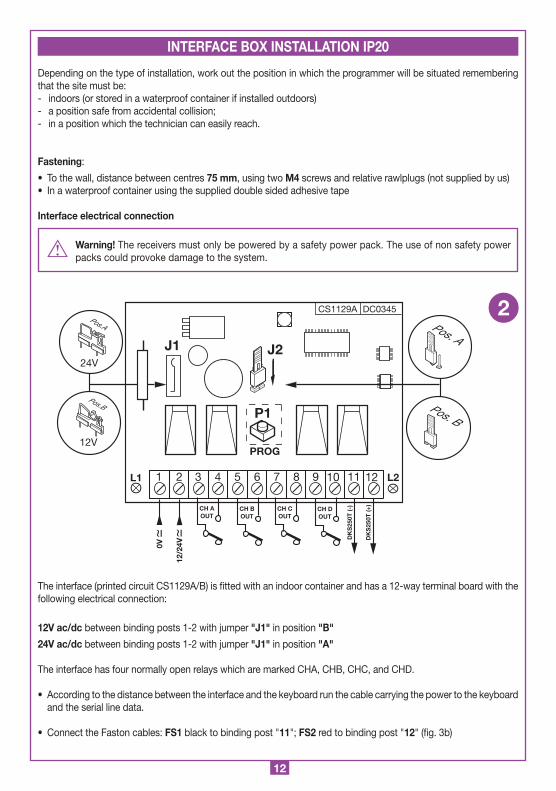
Depending on the type of installation, work out the position in which the programmer will be situated remembering that the site must be:- indoors (or stored in a waterproof container if installed outdoors)- a position safe from accidental collision;- in a position which the technician can easily reach.
Fastening:
• To the wall, distance between centres 75 mm, using two M4 screws and relative rawlplugs (not supplied by us) • In a waterproof container using the supplied double sided adhesive tape
Interface electrical connection
Warning! The receivers must only be powered by a safety power pack. The use of non safety power packs could provoke damage to the system.
The interface (printed circuit CS1129A/B) is fitted with an indoor container and has a 12-way terminal board with the following electrical connection:
12V ac/dc between binding posts 1-2 with jumper "J1" in position "B"
24V ac/dc between binding posts 1-2 with jumper "J1" in position "A"
The interface has four normally open relays which are marked CHA, CHB, CHC, and CHD.
• According to the distance between the interface and the keyboard run the cable carrying the power to the keyboard and the serial line data.
• Connect the Faston cables: FS1 black to binding post "11"; FS2 red to binding post "12" (fig. 3b)
CS1129A DC0345
J2
P1
PROG
24V
12V
Pos.A
Pos.B
J1
12/2
4V0V
1 2 3 4 5 6 7 8 9 10 11 12
CH BOUT
CH AOUT
CH DOUT
CH COUT
DK
S25
0T (-
)
DK
S25
0T (+
)
L1 L2
Interfaccia
DKS250R
28-11-2001
DC0345 Description :
Product Code :
Date :
Drawing number :
P.J.Heath
CARDIN ELETTRONICA S.p.A - 31020 San Vendemiano (TV) Italy - via Raffaello, 36 Tel: 0438/401818 Fax: 0438/401831
Draft :
All rights reserved. Unauthorised copying or use of the information contained in this document is punishable by law
DKS250R
Pos. A
Pos. B
2
INTERFACE BOX INSTALLATION IP20

13
1) Pass the connecting cables, "1" coming from the interface, through the wall.
2) Drill the wall at the distance indicated in figure 3a (58 mm).
3) Insert the rawlplugs "2" supplied with the kit.
4) Fasten down the counterplate "3" using the screws "4" supplied with the kit.
5) Connect the Fastons on the wires "1" to the Fastons on the keyboard "5" (fig, 3a-3b): - the red wire of the keyboard connects to binding post 12 on the interface card - the black wire of the keyboard connects to binding post 11 on the interface card
6) Position the keyboard (fig 3b-3c) and fasten it down to the counter plate using the special screw "S1" and the tool "K1".
INSTALL THE OUTDOOR KEYBOARD IP57
A
1
2
5
8
0
3
6
94
7
*
B
C
D
Montaggio Tastiera DKS250T a superfice
DKS250T
28-11-2001
DM0557 Description :
Product Code :
Date :
Drawing number :
P.J.Heath
CARDIN ELETTRONICA S.p.A - 31020 San Vendemiano (TV) Italy - via Raffaello, 36 Tel: 0438/401818 Fax: 0438/401831
Draft :
All rights reserved. Unauthorised copying or use of the information contained in this document is punishable by law
58 mm
1
2 3
4
5
3a
Montaggio Tastiera DKS250T a superfice
DKS250T
04-03-2002
DM0670 Description :
Product Code :
Date :
Drawing number :
P.J.Heath
CARDIN ELETTRONICA S.p.A - 31020 San Vendemiano (TV) Italy - via Raffaello, 36 Tel: 0438/401818 Fax: 0438/401831
Draft :
All rights reserved. Unauthorised copying or use of the information contained in this document is punishable by law
FS
1 (-) Bl
FS
2 (+) Rd
FASTON
A
1
2
5
8
0
3
6
94
7
*
B
C
D
Montaggio Tastiera DKS250T a superfice
DKS250T
28-11-2001
DM0669 Description :
Product Code :
Date :
Drawing number :
P.J.Heath
CARDIN ELETTRONICA S.p.A - 31020 San Vendemiano (TV) Italy - via Raffaello, 36 Tel: 0438/401818 Fax: 0438/401831
Draft :
All rights reserved. Unauthorised copying or use of the information contained in this document is punishable by law
K1
S1
3b
3c
Rd.= Red
Bl.= Black

14
L2ON
Attention! Before memorising the transmitters for the first time remember to cancel the entire memory content.
1a Remove jumper "J2" from the interface
1b Press button "P1" 3 times in sequence on the interface
1c Press button "P1" once more for six seconds on the interface
1d The green LED "L1" and the red LED "L2" will flash and remain lit during cancelling
1e The red LED "L2" switches off and the green LED "L1" will flash for a few seconds then it too will switch off
At this point all codes have been cancelled!
2a Insert jumper "J2" on the interface
2b Press button "P1" for at least six seconds
2c Red LED "L2" on the interface will flash
1 2 3
6 sec
L2ON
L1ON
L2OFF
L1ON
1. Cancelling the entire memory content
PROGRAMMING PROCEDURE
Pos. A
2. Memorising the programming function access code for remote memorisation from the keyboard
6 sec
Pos. B

15
2d Type the function access code into the keyboard (max 6 digits e.g. 1-2-3-4-5-6) and press confirm "*"
2e The green LED "L1" will flash and the red LED "L2" will switch off on the interface.
The access code has been memorised!
3a Remove jumper "J2" from the interface
3b Press button "P1" on the interface for at least three seconds
3c The red LED "L2" will flash on the interface
At this point the memorising procedure is active!
3d Type the desired numerical code into the keyboard (max 6 digits e.g. 1-2-3-4-5-6) and press confirm "*"
3e The keyboard will emit one beep for two seconds and the green LED will light up
The code has been accepted
3f Within 13 seconds of confirming the code press one or more functions A-B-C-D in sequence (e.g. A-C)
3g Press confirm "*" and the key board will emit a beep
3h The green LED "L1" will flash on the interface The code has been memorised and the functions have been assigned (e.g. A-C).
8
0
94
7
*
D
1
23
6
B
C
ON
A
1
2
5
8
3
6
94
B
C
D
8
0
94
7
*
D
L1ON
*
8
0
94
7
*
D
L1ON
L2OFF
*
*
3. Storing codes and selecting functions
3 sec
L2ON
Pos. A
16
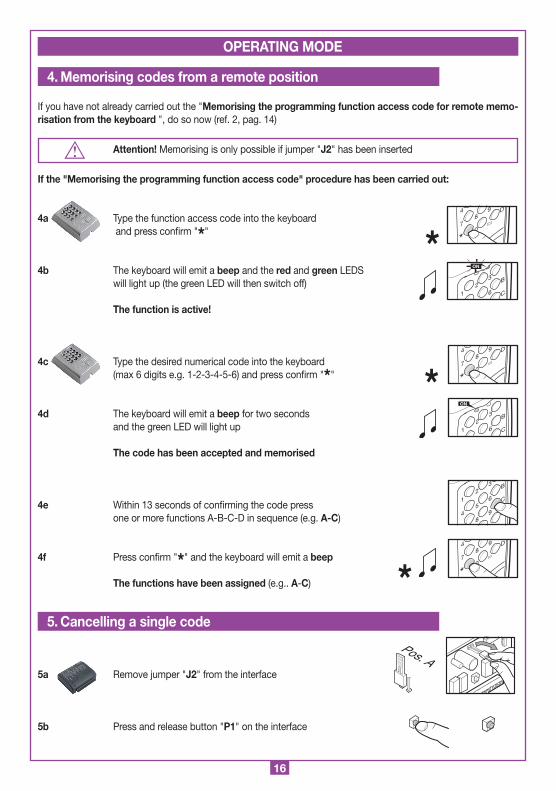
If you have not already carried out the "Memorising the programming function access code for remote memo-risation from the keyboard ", do so now (ref. 2, pag. 14)
Attention! Memorising is only possible if jumper "J2" has been inserted
If the "Memorising the programming function access code" procedure has been carried out:
4a Type the function access code into the keyboard and press confirm "*"
4b The keyboard will emit a beep and the red and green LEDS will light up (the green LED will then switch off)
The function is active!
4c Type the desired numerical code into the keyboard (max 6 digits e.g. 1-2-3-4-5-6) and press confirm "*"
4d The keyboard will emit a beep for two seconds and the green LED will light up
The code has been accepted and memorised
4e Within 13 seconds of confirming the code press one or more functions A-B-C-D in sequence (e.g. A-C)
4f Press confirm "*" and the keyboard will emit a beep
The functions have been assigned (e.g.. A-C)
5a Remove jumper "J2" from the interface
5b Press and release button "P1" on the interface
OPERATING MODE
4. Memorising codes from a remote position
*
*
8
0
94
7
*
D
8
0
94
7
*
D
1
23
6
B
C
ON
5. Cancelling a single code
Pos. A
1
23
6
B
C
ON
A
1
2
5
8
3
6
94
B
C
D
8
0
94
7
*
D
*

17
5c Press button "P1" on the interface for another 3 seconds.
5d The green LED "L1" and the red LED "L2" will light up on the interface.
The device is ready to cancel!
5e Type in the numerical code to be cancelled and press confirm "*"
5f The green LED "L1" will flash on the interface.
The code has been cancelled!
Attention! Cancelling is only possible if jumper "J2" has been inserted
6a Type the following sequence into the keyboard #*(code to cancel)*# (for example if you want to cancel 112233, type in #*112233*#)
6b The keyboard will emit a beep for two seconds the green LED and red LED will light up
The code has been cancelled!
3 sec
L2ON
L1ON
L1ON
*8
0
94
7
*
D
6. Cancelling a single code from a remote position
1
23
6
B
C
ON
18
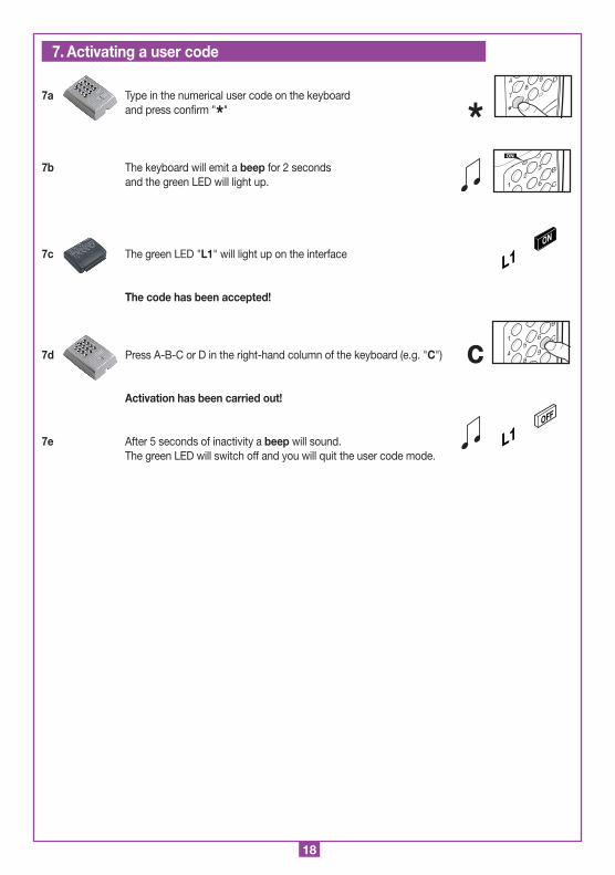
7a Type in the numerical user code on the keyboard and press confirm "*"
7b The keyboard will emit a beep for 2 seconds and the green LED will light up.
7c The green LED "L1" will light up on the interface
The code has been accepted!
7d Press A-B-C or D in the right-hand column of the keyboard (e.g. "C")
Activation has been carried out!
7e After 5 seconds of inactivity a beep will sound. The green LED will switch off and you will quit the user code mode.
7. Activating a user code
L1ON
*8
0
94
7
*
D
1
23
6
B
C
ON
L1OFF
c1
5
8
6
94
B
C

19
• Inserting a code with more than 6 digits will cancel the operation in progress. Signal: the keyboard will emit a beep.
• The available time between inserting one digit and the next is 5 seconds. Once the time has expired the operation will be cancelled.
• "Code memorisation": once the code has been memorised the device will automatically quit the procedure after 20 seconds has elapsed.
Signal: the red LED will flash on the keyboard and 6 consecutive beeps will sound
• Before memorising the transmitters for the first time remember to cancel the entire memory content.
• Only one remote code memorising access code can be stored. To change it you need only repeat the procedure and save the new code.
• Cancelling the entire memory content will also cancel the remote code memorising access code.
• After 5 attempts to insert and incorrect code (doesn't exist in memory) the system will remain blocked for 60 sec-onds.
Signal: the keyboard will sound 1 beep and both LEDS will flash for 5 seconds.
Interface - the red LED flashes:- memory full (attempt to memorise has failed)- code doesn't exist (during memorisation)- code doesn't exist (during cancellation)
Keyboard - the red LED flashes:- together with three slow beeps, code doesn't exist (during memorisation)- code doesn't exist (during cancellation)- together with three fast beeps, code doesn't exist in the operating mode.
NOTES
Warnings
Error signals
20
FRANÇAIS REMARQUE FRANÇAIS
(dimensioni d'ingombro)
21-05-97
DM0275 Description :
Product Code :
Date :
Drawing number :
P.J.Heath
CARDIN ELETTRONICA S.p.A - 31020 San Vendemiano (TV) Italy - via Raffaello, 36 Tel: 0438/401818 Fax: 0438/401831
Draft :
All rights reserved. Unauthorised copying or use of the information contained in this document is punishable by law
RXRADO RXRADO
95
25
75
A
1
2
5
8
0
3
6
94
7
*
B
C
D
2672
104
Montaggio Tastiera DKS250T a superfice
DKS250T
28-11-2001
DM0557 Description :
Product Code :
Date :
Drawing number :
P.J.Heath
CARDIN ELETTRONICA S.p.A - 31020 San Vendemiano (TV) Italy - via Raffaello, 36 Tel: 0438/401818 Fax: 0438/401831
Draft :
All rights reserved. Unauthorised copying or use of the information contained in this document is punishable by law
Avant de procéder à l'installation, lire attentivement ce livret. En particulier, se familiariser avec les dispositifs de sécurité prévus sur le produit afin de pouvoir les utiliser au mieux. Avant d’engager la programmation, lire attentivement les "NOTES" à la page 28. Une diverse utilisation des produits ou leur destination à un usage différent de ceux prévus et/ou conseillés n'a pas été expérimentée par le fabricant. Par conséquent, les travaux effectués sont entièrement sous la responsabilité de l'installateur. Ce livret est destiné à des personnes titulaires d'un certificat d'aptitude professionnelle pour l'installation des "APPAREILS ÉLECTRIQUES" et requiert une bonne connaissance de la technique appliquée professionnellement. Le Cons-tructeur décline toute responsabilité pour les éventuels dommages entraînés par la non observation des normes de sécurité en vigueur actuellement durant l'installation des appareils.
Descriptif
Le système se compose de deux éléments, l’un branché à l’autre au moyen d’un câble:- DKS250T clavier numérique pour l’extérieur, - DKS250R interface pour le branchement sériel.
Le clavier est constitué d’une structure métallique antivandale en zamac, peinture haute résistance, et touches chromées résistant à l’usure. Facile à poser, il bénéficie d’un indice de protection IP57 et d’un système de fixation antivandale avec vis et clé spéciales.Il est doté de:- LED rouge de signalisation - LED verte de signalisation- 10 touches numériques (0-9)- une touche de confirmation *- une touche d’annulation de l’opération #- 4 fonctions de canal (A, B, C, D) - avertisseur sonore.
L’interface, logée sous boîtier pour l’intérieur IP20, se raccorde au clavier à travers un câble téléphonique (ou similaire) à deux conducteurs de Ø 0,6 mm, d’une longueur maximum de 150 m, et est dotée d’une touche de programmation, et de deux leds, verte L1 et rouge L2, pour la signalisation visuelle.
Domaine d’application
Le système DKS250 permet l’actionnement, à travers câble, d’appareils électriques et électroniques, en toute sécurité. Il est particulièrement indiqué pour la commande de portes motorisées.
Nombre de codes usager mémorisables (chacun de 6 chiffres maxi.) ................................................................................... 250Nombre de combinaisons de codes .................................................................................................................................1 million
CARACTÉRISTIQUES TECHNIQUES
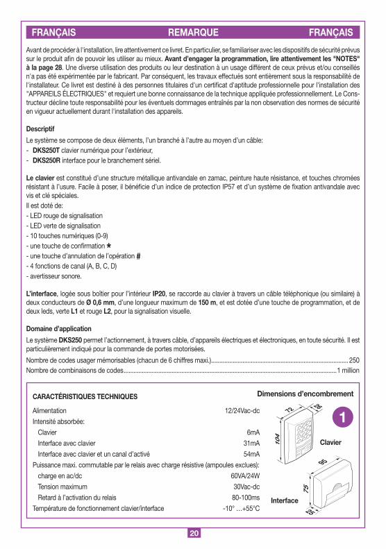
Alimentation 12/24Vac-dc
Intensité absorbée:
Clavier 6mA
Interface avec clavier 31mA
Interface avec clavier et un canal d’activé 54mA
Puissance maxi. commutable par le relais avec charge résistive (ampoules exclues):
charge en ac/dc 60VA/24W
Tension maximum 30Vac-dc
Retard à l’activation du relais 80-100ms
Température de fonctionnement clavier/interface -10° …+55°C
1
Dimensions d’encombrement
Interface
Clavier
21
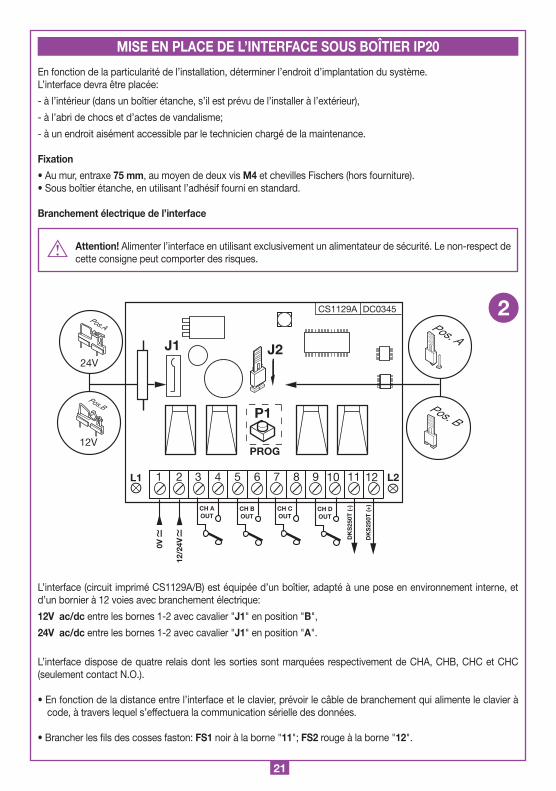
En fonction de la particularité de l’installation, déterminer l’endroit d’implantation du système.L’interface devra être placée:
- à l’intérieur (dans un boîtier étanche, s’il est prévu de l’installer à l’extérieur),
- à l’abri de chocs et d’actes de vandalisme;
- à un endroit aisément accessible par le technicien chargé de la maintenance.
Fixation
• Au mur, entraxe 75 mm, au moyen de deux vis M4 et chevilles Fischers (hors fourniture).• Sous boîtier étanche, en utilisant l’adhésif fourni en standard.
Branchement électrique de l’interface
Attention! Alimenter l’interface en utilisant exclusivement un alimentateur de sécurité. Le non-respect de cette consigne peut comporter des risques.
L’interface (circuit imprimé CS1129A/B) est équipée d’un boîtier, adapté à une pose en environnement interne, et d’un bornier à 12 voies avec branchement électrique:
12V ac/dc entre les bornes 1-2 avec cavalier "J1" en position "B",
24V ac/dc entre les bornes 1-2 avec cavalier "J1" en position "A".
L’interface dispose de quatre relais dont les sorties sont marquées respectivement de CHA, CHB, CHC et CHC (seulement contact N.O.).
• En fonction de la distance entre l’interface et le clavier, prévoir le câble de branchement qui alimente le clavier à code, à travers lequel s’effectuera la communication sérielle des données.
• Brancher les fils des cosses faston: FS1 noir à la borne "11"; FS2 rouge à la borne "12".
CS1129A DC0345
J2
P1
PROG
24V
12V
Pos.A
Pos.B
J1
12/2
4V0V
1 2 3 4 5 6 7 8 9 10 11 12
CH BOUT
CH AOUT
CH DOUT
CH COUT
DK
S25
0T (-
)
DK
S25
0T (+
)
L1 L2
Interfaccia
DKS250R
28-11-2001
DC0345 Description :
Product Code :
Date :
Drawing number :
P.J.Heath
CARDIN ELETTRONICA S.p.A - 31020 San Vendemiano (TV) Italy - via Raffaello, 36 Tel: 0438/401818 Fax: 0438/401831
Draft :
All rights reserved. Unauthorised copying or use of the information contained in this document is punishable by law
DKS250R
Pos. A
Pos. B
2
MISE EN PLACE DE L’INTERFACE SOUS BOÎTIER IP20

22
1) Faire passer les fils de branchement "1", qui proviennent de l’interface, à travers le mur.
2) Perforer le mur en respectant la distance indiquée sur la figure 3a (58 mm).
3) Introduire les chevilles (fischer) "2" fournies avec le kit.
4) Fixer la contreplaque "3" au moyen des vis "4" fournies avec le kit.
5) Brancher les cosses faston des fils "1" aux cosses faston du clavier "5" (fig. 3a-3b): - fil rouge du clavier à la borne 12 de l’interface, - fil noir du clavier à la borne 11 de l’interface
6) Après quoi, positionner le clavier (fig. 3b-3c) et le fixer à la contreplaque au moyen de la vis spéciale "S1" et de l’outil "K1" expressément prévu à cet effet
A
1
2
5
8
0
3
6
94
7
*
B
C
D
Montaggio Tastiera DKS250T a superfice
DKS250T
28-11-2001
DM0557 Description :
Product Code :
Date :
Drawing number :
P.J.Heath
CARDIN ELETTRONICA S.p.A - 31020 San Vendemiano (TV) Italy - via Raffaello, 36 Tel: 0438/401818 Fax: 0438/401831
Draft :
All rights reserved. Unauthorised copying or use of the information contained in this document is punishable by law
58 mm
1
2 3
4
5
3a
Montaggio Tastiera DKS250T a superfice
DKS250T
04-03-2002
DM0670 Description :
Product Code :
Date :
Drawing number :
P.J.Heath
CARDIN ELETTRONICA S.p.A - 31020 San Vendemiano (TV) Italy - via Raffaello, 36 Tel: 0438/401818 Fax: 0438/401831
Draft :
All rights reserved. Unauthorised copying or use of the information contained in this document is punishable by law
FS
1 (-) Bl
FS
2 (+) Rd
FASTON
A
1
2
5
8
0
3
6
94
7
*
B
C
D
Montaggio Tastiera DKS250T a superfice
DKS250T
28-11-2001
DM0669 Description :
Product Code :
Date :
Drawing number :
P.J.Heath
CARDIN ELETTRONICA S.p.A - 31020 San Vendemiano (TV) Italy - via Raffaello, 36 Tel: 0438/401818 Fax: 0438/401831
Draft :
All rights reserved. Unauthorised copying or use of the information contained in this document is punishable by law
K1
S1
3b
3c
MISE EN PLACE DU CLAVIER POUR L’EXTÉRIEUR IP57
Rd.= Rouge
Bl.= Noir

23
Attention! Avant d’effectuer la première mémorisation de codes, se rappeler d’effacer entièrement la mémoire.
1a Ouvrir le cavalier "J2" sur l’interface
1b Appuyer trois fois de suite sur le bouton "P1" sur l’interface
1c Appuyer une autre fois pendant 6 secondes sur le bouton "P1" sur l’interface
1d Les LEDS, "L1" verte et "L2" rouge, clignotent et restent allumées pendant l’effacement
1e Le LED rouge "L2" s’éteint, tandis que la LED verte "L1" clignote pendant quelques instants avant de s’éteindre à son tour
À ce point, tous les codes ont été effacés!
2a Fermer le cavalier "J2" sur l’interface.
2b Appuyer sur le bouton "P1" pendant au moins 6 secondes
2c La LED rouge "L2" sur l’interface s’allume.
1 2 3
6 sec
L2ON
L1ON
L2OFF
L1ON
1. Effacement total de la mémoire
PROCÉDÉ DE PROGRAMMATION
Pos. A
2. Mémorisation du code d’accès aux fonctions de programmation à distance du clavier
6 sec
L2ON
Pos. B

24
2d Taper sur le clavier le code numérique d’accès aux fonctions (maxi. 6 chiffres, ex. 1-2-3-4-5-6), et appuyer sur confirmation "*".
2e Sur l’interface, la LED verte "L1" clignote et la LED rouge "L2" s’éteint.
La mémorisation du code d’accès a eu lieu!
3a Ouvrir le cavalier "J2" sur l’interface
3b Appuyer sur le bouton "P1" sur l’interface pendant au moins 3 secondes
3c La LED rouge "L2" sur l’interface s’allume.
À ce point, le procédé de mémorisation est activé!
3d Taper sur le clavier le code numérique désiré (maxi. 6 chiffres, ex. 1-2-3-4-5-6), et appuyer sur confirmation "*"
3e Le clavier émet un bip pendant 2 secondes + LED verte allumée.
Le code a été accepté
3f Dans les 13 secondes qui suivent la confirmation du code, appuyer sur une ou plusieurs fonctions A-B-C-D en respectant la séquence (Ex. A-C)
3g Appuyer sur confirmation "*"; le clavier émet un bip
3h Sur l’interface, la LED verte "L1" clignote Le code a été mémorisé, et les fonctions assignées (Ex. A-C).
8
0
94
7
*
D
1
23
6
B
C
ON
A
1
2
5
8
3
6
94
B
C
D
8
0
94
7
*
D
L1ON
*
8
0
94
7
*
D
L1ON
L2OFF
*
*
3. Mémorisation des codes et sélection des fonctions
3 sec
L2ON
Pos. A

25
Si la "Mémorisation du code d’accès à la programmation à distance" n’a pas été effectuée précédemment, exécuter tout le procédé (réf. 2, page 23)
Attention! La mémorisation n’est faisable que si le cavalier "J2" est connecté.
Si la "Mémorisation du code d’accès à la programmation à distance" a été effectuée:
4a Taper sur le clavier le code d’accès à la mémorisation, et appuyer sur confirmation "*"
4b Le clavier émet un bip, et les LEDS rouge et verte s’allument (ensuite, la LED verte s’éteint)
La fonction est activée!
4c Taper sur le clavier le nouveau code numérique à mémoriser (maxi. 6 chiffres, ex. 1-2-3-4-5-6), et appuyer sur confirmation "*"
4d Le clavier émet un bip pendant 2 secondes + LED verte allumée.
Le code a été accepté et mémorisé
4e Dans les 13 secondes qui suivent la confirmation du code, appuyer sur une ou plusieurs fonctions A-B-C-D en respectant la séquence (Ex. A-C)
4f Appuyer sur confirmation "*"; le clavier émet un bip
Les fonctions ont été assignées (Ex. A-C)
5a Ouvrir le cavalier "J2" sur l’interface
5b Sur l’interface, appuyer sur le bouton "P1" et le relâcher
MODE DE FONCTIONNEMENT
4. Mémorisation des codes à distance
*
*
8
0
94
7
*
D
8
0
94
7
*
D
1
23
6
B
C
ON
5. Effacement d’un code
Pos. A
1
23
6
B
C
ON
A
1
2
5
8
3
6
94
B
C
D
8
0
94
7
*
D
*
26
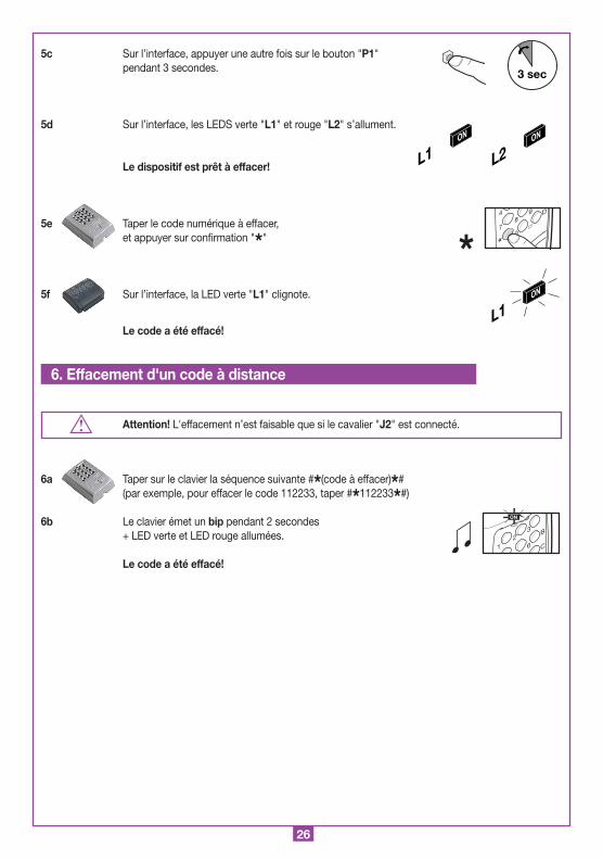
5c Sur l’interface, appuyer une autre fois sur le bouton "P1" pendant 3 secondes.
5d Sur l’interface, les LEDS verte "L1" et rouge "L2" s’allument.
Le dispositif est prêt à effacer!
5e Taper le code numérique à effacer, et appuyer sur confirmation "*"
5f Sur l’interface, la LED verte "L1" clignote.
Le code a été effacé!
Attention! L'effacement n’est faisable que si le cavalier "J2" est connecté.
6a Taper sur le clavier la séquence suivante #*(code à effacer)*# (par exemple, pour effacer le code 112233, taper #*112233*#)
6b Le clavier émet un bip pendant 2 secondes + LED verte et LED rouge allumées.
Le code a été effacé!
3 sec
L2ON
L1ON
L1ON
*8
0
94
7
*
D
6. Effacement d'un code à distance
1
23
6
B
C
ON

27
7a Taper sur le clavier le code numérique de l’usager, et appuyer sur confirmation "*"
7b Le clavier émet un bip pendant 2 secondes + LED verte allumée
7c La LED "L1" s’allume sur l’interface
Code accepté!
7d Appuyer sur A-B-C ou D dans la colonne à droite sur le clavier (Ex. "C")
Activation exécutée!
7e Après 5 secondes sans intervenir, un bip retentit, la LED verte s’éteint, et on quitte la programmation.
7. Activation du code usager
L1ON
*8
0
94
7
*
D
1
23
6
B
C
ON
L1OFF
c1
5
8
6
94
B
C

28
• L’introduction d’un code composé de plus de 6 chiffres annule l’opération en cours. Type de signalisation: le clavier émet un bip.
• Le temps à disposition entre une introduction de code et la successive est de 5 secondes. Une fois que ce laps de temps s’est écoulé, l’opération s’annule.
• "Mémorisation de codes ": 20 sec. après que le code ait été mémorisé, on quitte automatiquement le procédé. Type de signalisation: sur le clavier, la LED rouge clignote, et une série de 6 bips se déclenche.
• Avant de procéder à la première mémorisation de codes, effacer toute la mémoire.
• Il est possible de mémoriser un seul code d’accès à la mémorisation à distance. Pour le modifier, il suffit de répéter le procédé et de mémoriser le nouveau code.
• L’effacement total de la mémoire annule également le code d’accès à la mémorisation à distance.
• Si l’on introduit 5 fois de suite un code erroné (qui n’existe pas en mémoire), le système se bloque pendant 60 sec. Type de signalisation: le clavier émet un bip, et les deux leds clignotent pendant 5 sec.
Interface – LED rouge clignotante:- mémoire saturée- code existant (en mémoire)- code inexistant (en phase d’effacement)
Clavier - LED rouge clignotante:- accompagnée de trois bips lents, code existant (en mémoire)- code inexistant (en phase d’effacement)- accompagnée de trois bips rapides, code erroné durant le fonctionnement.
NOTES
Remarque
Signalisations d’erreur
29
DEUTSCH ANWEISUNGEN DEUTSCH
(dimensioni d'ingombro)
21-05-97
DM0275 Description :
Product Code :
Date :
Drawing number :
P.J.Heath
CARDIN ELETTRONICA S.p.A - 31020 San Vendemiano (TV) Italy - via Raffaello, 36 Tel: 0438/401818 Fax: 0438/401831
Draft :
All rights reserved. Unauthorised copying or use of the information contained in this document is punishable by law
RXRADO RXRADO
95
25
75
A
1
2
5
8
0
3
6
94
7
*
B
C
D
2672
104
Montaggio Tastiera DKS250T a superfice
DKS250T
28-11-2001
DM0557 Description :
Product Code :
Date :
Drawing number :
P.J.Heath
CARDIN ELETTRONICA S.p.A - 31020 San Vendemiano (TV) Italy - via Raffaello, 36 Tel: 0438/401818 Fax: 0438/401831
Draft :
All rights reserved. Unauthorised copying or use of the information contained in this document is punishable by law
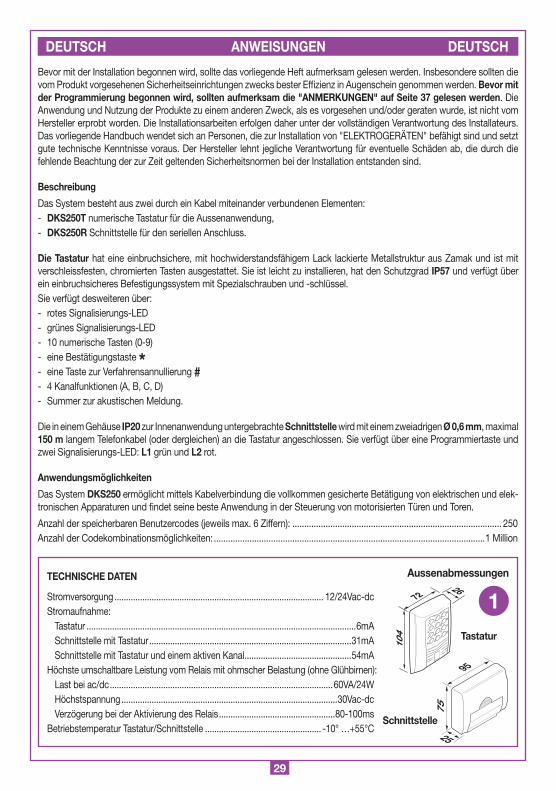
Bevor mit der Installation begonnen wird, sollte das vorliegende Heft aufmerksam gelesen werden. Insbesondere sollten die vom Produkt vorgesehenen Sicherheitseinrichtungen zwecks bester Effizienz in Augenschein genommen werden. Bevor mit der Programmierung begonnen wird, sollten aufmerksam die "ANMERKUNGEN" auf Seite 37 gelesen werden. Die Anwendung und Nutzung der Produkte zu einem anderen Zweck, als es vorgesehen und/oder geraten wurde, ist nicht vom Hersteller erprobt worden. Die Installationsarbeiten erfolgen daher unter der vollständigen Verantwortung des Installateurs. Das vorliegende Handbuch wendet sich an Personen, die zur Installation von "ELEKTROGERÄTEN" befähigt sind und setzt gute technische Kenntnisse voraus. Der Hersteller lehnt jegliche Verantwortung für eventuelle Schäden ab, die durch die fehlende Beachtung der zur Zeit geltenden Sicherheitsnormen bei der Installation entstanden sind.
Beschreibung
Das System besteht aus zwei durch ein Kabel miteinander verbundenen Elementen:- DKS250T numerische Tastatur für die Aussenanwendung,- DKS250R Schnittstelle für den seriellen Anschluss.
Die Tastatur hat eine einbruchsichere, mit hochwiderstandsfähigem Lack lackierte Metallstruktur aus Zamak und ist mit verschleissfesten, chromierten Tasten ausgestattet. Sie ist leicht zu installieren, hat den Schutzgrad IP57 und verfügt über ein einbruchsicheres Befestigungssystem mit Spezialschrauben und -schlüssel.Sie verfügt desweiteren über:- rotes Signalisierungs-LED- grünes Signalisierungs-LED- 10 numerische Tasten (0-9)- eine Bestätigungstaste *- eine Taste zur Verfahrensannullierung #- 4 Kanalfunktionen (A, B, C, D)- Summer zur akustischen Meldung.
Die in einem Gehäuse IP20 zur Innenanwendung untergebrachte Schnittstelle wird mit einem zweiadrigen Ø 0,6 mm, maximal 150 m langem Telefonkabel (oder dergleichen) an die Tastatur angeschlossen. Sie verfügt über eine Programmiertaste und zwei Signalisierungs-LED: L1 grün und L2 rot.
Anwendungsmöglichkeiten
Das System DKS250 ermöglicht mittels Kabelverbindung die vollkommen gesicherte Betätigung von elektrischen und elek-tronischen Apparaturen und findet seine beste Anwendung in der Steuerung von motorisierten Türen und Toren.
Anzahl der speicherbaren Benutzercodes (jeweils max. 6 Ziffern): ........................................................................................ 250Anzahl der Codekombinationsmöglichkeiten: ..................................................................................................................1 Million
TECHNISCHE DATEN
Stromversorgung .......................................................................................... 12/24Vac-dcStromaufnahme:
Tastatur ....................................................................................................................6mASchnittstelle mit Tastatur .......................................................................................31mASchnittstelle mit Tastatur und einem aktiven Kanal ..............................................54mA
Höchste umschaltbare Leistung vom Relais mit ohmscher Belastung (ohne Glühbirnen):Last bei ac/dc ................................................................................................60VA/24WHöchstspannung .............................................................................................30Vac-dcVerzögerung bei der Aktivierung des Relais ..................................................80-100ms
Betriebstemperatur Tastatur/Schnittstelle .................................................. -10° …+55°C
1Aussenabmessungen
Schnittstelle
Tastatur
30
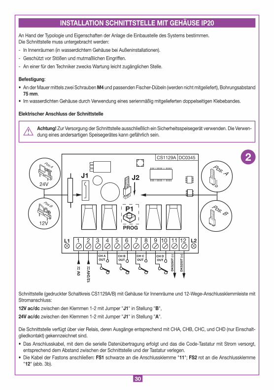
An Hand der Typologie und Eigenschaften der Anlage die Einbaustelle des Systems bestimmen.Die Schnittstelle muss untergebracht werden:
- In Innenräumen (in wasserdichtem Gehäuse bei Außeninstallationen).
- Geschützt vor Stößen und mutmaßlichen Eingriffen.
- An einer für den Techniker zwecks Wartung leicht zugänglichen Stelle.
Befestigung:
• An der Mauer mittels zwei Schrauben M4 und passenden Fischer-Dübeln (werden nicht mitgeliefert), Bohrungsabstand 75 mm.
• Im wasserdichten Gehäuse durch Verwendung eines serienmäßig mitgelieferten doppelseitigen Klebebandes.
Elektrischer Anschluss der Schnittstelle
Achtung! Zur Versorgung der Schnittstelle ausschließlich ein Sicherheitsspeisegerät verwenden. Die Verwen-dung eines andersartigen Speisegerätes kann gefährlich sein.
Schnittstelle (gedruckter Schaltkreis CS1129A/B) mit Gehäuse für Innenräume und 12-Wege-Anschlussklemmleiste mit Stromanschluss:
12V ac/dc zwischen den Klemmen 1-2 mit Jumper "J1" in Stellung "B",
24V ac/dc zwischen den Klemmen 1-2 mit Jumper "J1" in Stellung "A".
Die Schnittstelle verfügt über vier Relais, deren Ausgänge entsprechend mit CHA, CHB, CHC, und CHD (nur Einschalt-gliedkontakt) gekennzeichnet sind.
• Das Anschlusskabel, mit dem die serielle Datenübertragung erfolgt und das die Code-Tastatur mit Strom versorgt, entsprechend dem Abstand zwischen der Schnittstelle und der Tastatur verlegen.
• Die Kabel der Fastons anschließen: FS1 schwarze an die Anschlussklemme "11"; FS2 rot an die Anschlussklemme "12" (abb. 3b).
CS1129A DC0345
J2
P1
PROG
24V
12V
Pos.A
Pos.B
J1
12/2
4V0V
1 2 3 4 5 6 7 8 9 10 11 12
CH BOUT
CH AOUT
CH DOUT
CH COUT
DK
S25
0T (-
)
DK
S25
0T (+
)
L1 L2
Interfaccia
DKS250R
28-11-2001
DC0345 Description :
Product Code :
Date :
Drawing number :
P.J.Heath
CARDIN ELETTRONICA S.p.A - 31020 San Vendemiano (TV) Italy - via Raffaello, 36 Tel: 0438/401818 Fax: 0438/401831
Draft :
All rights reserved. Unauthorised copying or use of the information contained in this document is punishable by law
DKS250R
Pos. A
Pos. B
2
INSTALLATION SCHNITTSTELLE MIT GEHÄUSE IP20

31
1) Die von der Schnittstelle kommenden Anschlusskabel "1" durch die Mauer führen.
2) Die Mauer in dem wie in der Abbildung 3a angezeigten Abstand (58 mm) anbohren.
3) Die mit dem Bausatz mitgelieferten Fischer-Dübel "2" einstecken.
4) Die Befestigungsplatte "3" mit den im Bausatz mitgelieferten Schrauben "4" befestigen.
5) Die Fastons der Kabel "1" mit den Fastons der Tastatur "5" (Abb. 3a-3b) verbinden:- rote Leitung von der Tastatur an die Anschlussklemme 12 der Schnittstelle- schwarze Leitung von der Tastatur an die Anschlussklemme 11 der Schnittstelle
6) Nun die Tastatur positionieren (Abb. 3b-3c) und mit der Spezialschraube "S1" unter Verwendung des dafür vorgesehenen Werkzeuges "K1" an der Befestigungsplatte befestigen.
A
1
2
5
8
0
3
6
94
7
*
B
C
D
Montaggio Tastiera DKS250T a superfice
DKS250T
28-11-2001
DM0557 Description :
Product Code :
Date :
Drawing number :
P.J.Heath
CARDIN ELETTRONICA S.p.A - 31020 San Vendemiano (TV) Italy - via Raffaello, 36 Tel: 0438/401818 Fax: 0438/401831
Draft :
All rights reserved. Unauthorised copying or use of the information contained in this document is punishable by law
58 mm
1
2 3
4
5
3a
Montaggio Tastiera DKS250T a superfice
DKS250T
04-03-2002
DM0670 Description :
Product Code :
Date :
Drawing number :
P.J.Heath
CARDIN ELETTRONICA S.p.A - 31020 San Vendemiano (TV) Italy - via Raffaello, 36 Tel: 0438/401818 Fax: 0438/401831
Draft :
All rights reserved. Unauthorised copying or use of the information contained in this document is punishable by law
FS
1 (-) Bl
FS
2 (+) Rd
FASTON
A
1
2
5
8
0
3
6
94
7
*
B
C
D
Montaggio Tastiera DKS250T a superfice
DKS250T
28-11-2001
DM0669 Description :
Product Code :
Date :
Drawing number :
P.J.Heath
CARDIN ELETTRONICA S.p.A - 31020 San Vendemiano (TV) Italy - via Raffaello, 36 Tel: 0438/401818 Fax: 0438/401831
Draft :
All rights reserved. Unauthorised copying or use of the information contained in this document is punishable by law
K1
S1
3b
3c
INSTALLATION TASTATUR FÜR AUSSENANWENDUNG IP57
Rd.= Rote
Bl.= Schwarz
32
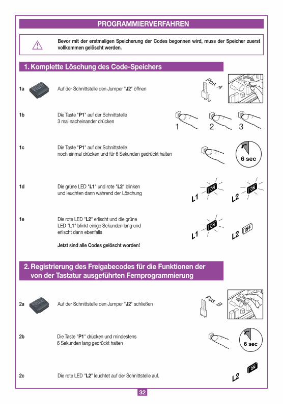
Bevor mit der erstmaligen Speicherung der Codes begonnen wird, muss der Speicher zuerst vollkommen gelöscht werden.
1a Auf der Schnittstelle den Jumper "J2" öffnen
1b Die Taste "P1" auf der Schnittstelle 3 mal nacheinander drücken
1c Die Taste "P1" auf der Schnittstelle noch einmal drücken und für 6 Sekunden gedrückt halten
1d Die grüne LED "L1" und rote "L2" blinken und leuchten dann während der Löschung
1e Die rote LED "L2" erlischt und die grüne LED "L1" blinkt einige Sekunden lang und erlischt dann ebenfalls
Jetzt sind alle Codes gelöscht worden!
2a Auf der Schnittstelle den Jumper "J2" schließen
2b Die Taste "P1" drücken und mindestens 6 Sekunden lang gedrückt halten
2c Die rote LED "L2" leuchtet auf der Schnittstelle auf.
1 2 3
6 sec
L2ON
L1ON
L2OFF
L1ON
1. Komplette Löschung des Code-Speichers
PROGRAMMIERVERFAHREN
Pos. A
2. Registrierung des Freigabecodes für die Funktionen der von der Tastatur ausgeführten Fernprogrammierung
6 sec
L2ON
Pos. B
33
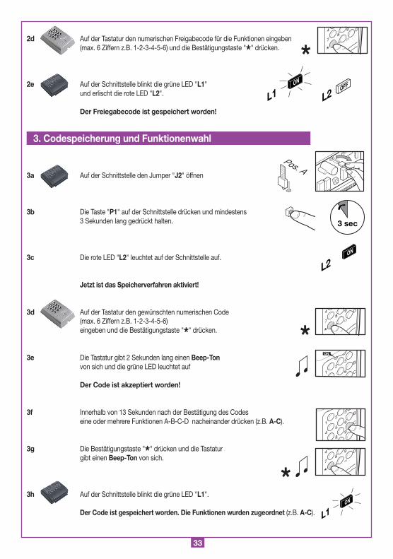
2d Auf der Tastatur den numerischen Freigabecode für die Funktionen eingeben (max. 6 Ziffern z.B. 1-2-3-4-5-6) und die Bestätigungstaste "*" drücken.
2e Auf der Schnittstelle blinkt die grüne LED "L1" und erlischt die rote LED "L2".
Der Freiegabecode ist gespeichert worden!
3a Auf der Schnittstelle den Jumper "J2" öffnen
3b Die Taste "P1" auf der Schnittstelle drücken und mindestens 3 Sekunden lang gedrückt halten.
3c Die rote LED "L2" leuchtet auf der Schnittstelle auf.
Jetzt ist das Speicherverfahren aktiviert!
3d Auf der Tastatur den gewünschten numerischen Code (max. 6 Ziffern z.B. 1-2-3-4-5-6) eingeben und die Bestätigungstaste "*" drücken.
3e Die Tastatur gibt 2 Sekunden lang einen Beep-Ton von sich und die grüne LED leuchtet auf
Der Code ist akzeptiert worden!
3f Innerhalb von 13 Sekunden nach der Bestätigung des Codes eine oder mehrere Funktionen A-B-C-D nacheinander drücken (z.B. A-C).
3g Die Bestätigungstaste "*" drücken und die Tastatur gibt einen Beep-Ton von sich.
3h Auf der Schnittstelle blinkt die grüne LED "L1". Der Code ist gespeichert worden. Die Funktionen wurden zugeordnet (z.B. A-C).
8
0
94
7
*
D
1
23
6
B
C
ON
A
1
2
5
8
3
6
94
B
C
D
8
0
94
7
*
D
L1ON
*
8
0
94
7
*
D
L1ON
L2OFF
*
*
3. Codespeicherung und Funktionenwahl
3 sec
L2ON
Pos. A
34
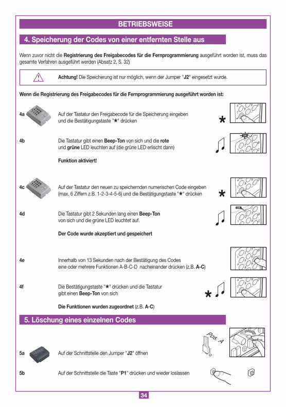
Wenn zuvor nicht die Registrierung des Freigabecodes für die Fernprogrammierung ausgeführt worden ist, muss das gesamte Verfahren ausgeführt werden (Absatz 2, S. 32)
Achtung! Die Speicherung ist nur möglich, wenn der Jumper "J2" eingesetzt wurde.
Wenn die Registrierung des Freigabecodes für die Fernprogrammierung ausgeführt worden ist:
4a Auf der Tastatur den Freigabecode für die Speicherung eingeben und die Bestätigungstaste "*" drücken
4b Die Tastatur gibt einen Beep-Ton von sich und die rote und grüne LED leuchten auf (die grüne LED erlischt dann)
Funktion aktiviert!
4c Auf der Tastatur den neuen zu speichernden numerischen Code eingeben (max. 6 Ziffern z.B. 1-2-3-4-5-6) und die Bestätigungstaste "*" drücken
4d Die Tastatur gibt 2 Sekunden lang einen Beep-Ton von sich und die grüne LED leuchtet auf.
Der Code wurde akzeptiert und gespeichert
4e Innerhalb von 13 Sekunden nach der Bestätigung des Codes eine oder mehrere Funktionen A-B-C-D nacheinander drücken (z.B. A-C)
4f Die Bestätigungstaste "*" drücken und die Tastatur gibt einen Beep-Ton von sich
Die Funktionen wurden zugeordnet (z.B. A-C)
5a Auf der Schnittstelle den Jumper "J2" öffnen
5b Auf der Schnittstelle die Taste "P1" drücken und wieder loslassen
BETRIEBSWEISE
4. Speicherung der Codes von einer entfernten Stelle aus
*
*
8
0
94
7
*
D
8
0
94
7
*
D
1
23
6
B
C
ON
5. Löschung eines einzelnen Codes
Pos. A
1
23
6
B
C
ON
A
1
2
5
8
3
6
94
B
C
D
8
0
94
7
*
D
*
35
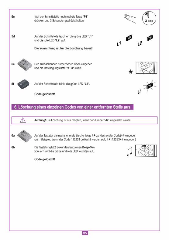
5c Auf der Schnittstelle noch mal die Taste "P1" drücken und 3 Sekunden gedrückt halten.
5d Auf der Schnittstelle leuchten die grüne LED "L1" und die rote LED "L2" auf.
Die Vorrichtung ist für die Löschung bereit!
5e Den zu löschenden numerischen Code eingeben und die Bestätigungstaste "*" drücken.
5f Auf der Schnittstelle blinkt die grüne LED "L1".
Code gelöscht!
Achtung! Die Löschung ist nur möglich, wenn der Jumper "J2" eingesetzt wurde.
6a Auf der Tastatur die nachstehende Zeichenfolge #*(zu löschender Code)*# eingeben (zum Beispiel: Wenn der Code 112233 gelöscht werden soll, #*112233*# eingeben)
6b Die Tastatur gibt 2 Sekunden lang einen Beep-Ton von sich und die grüne und rote LED leuchten auf.
Code gelöscht!
3 sec
L2ON
L1ON
L1ON
*8
0
94
7
*
D
6. Löschung eines einzelnen Codes von einer entfernten Stelle aus
1
23
6
B
C
ON

36
L1ON
*8
0
94
7
*
D
1
23
6
B
C
ON
L1OFF
c1
5
8
6
94
B
C
7a Auf der Tastatur den numerischen Benutzer-Code eingeben und die Bestätigungstaste "*" drücken
7b Die Tastatur gibt 2 Sekunden lang einen Beep-Ton von sich und die grüne LED leuchtet auf
7c Die grüne LED "L1" leuchtet auf der Schnittstelle auf
Code akzeptiert!
7d A-B-C oder D rechts auf der Tastatur drücken (z.B. "C").
Aktivierung ausgeführt!
7e Nach einer Inaktivität von 5 Sekunden ertönt ein Beep-Ton. Die grüne LED erlischt und es erfolgt der Austritt aus der Modalität.
7. Aktivierung des Benutzer-Codes

37
• Die Eingabe eines Codes mit mehr als 6 Ziffern annulliert das laufende Verfahren. Signalisierungsart: Die Tastatur gibt einen Beep-Ton von sich.
• Die zur Verfügung stehende Zeit zwischen der Eingabe der einzelnen Ziffern beträgt 5 Sekunden. Nach Ablauf der zur Verfügung stehenden Sekunden wird das Verfahren annulliert.
• "Speicherung der Codes": Nach der Speicherung des Codes erfolgt nach 20 Sekunden automatisch der Austritt aus dem Verfahren.
Signalisierungsart: Auf der Tastatur blinkt die rote LED und es werden 6 Beep-Töne nacheinander abgegeben.
• Bevor mit der erstmaligen Speicherung der Codes begonnen wird, muss der Speicher zuerst vollkommen gelöscht werden.
• Es kann nur ein einziger Freigabecode für die Fernspeicherung registriert werden. Zu dessen Änderung braucht nur das Verfahren wiederholt und der neue Code registriert zu werden.
• Die vollständige Löschung des Speichers löscht auch den Freigabecode für die Fernspeicherung.
• Nachdem 5mal nacheinander ein "falscher" Code (nicht im Speicher vorhanden) eingegeben wurde, wird das System für 60 Sekunden blockiert.
Signalisierungsart: Die Tastatur gibt einen Beep-Ton von sich und die beiden LED blinken 5 Sekunden lang.
Schnittstelle - rotes LED blinkt:- Speicher voll- Code vorhanden (im Speicherverfahren)- Code nicht vorhanden (im Löschverfahren)
Tastatur - rotes LED blinkend- begleitet von drei langsamen Beep-Tönen, Code vorhanden (im Speicherverfahren)- Code nicht vorhanden (im Löschverfahren)- begleitet von drei schnellen Beep-Tönen, falscher Code im Betriebsmodus.
ANMERKUNGEN
Hinweise
Fehlersignalisierung
38
ESPAÑOL ADVERTENCIAS ESPAÑOL
(dimensioni d'ingombro)
21-05-97
DM0275 Description :
Product Code :
Date :
Drawing number :
P.J.Heath
CARDIN ELETTRONICA S.p.A - 31020 San Vendemiano (TV) Italy - via Raffaello, 36 Tel: 0438/401818 Fax: 0438/401831
Draft :
All rights reserved. Unauthorised copying or use of the information contained in this document is punishable by law
RXRADO RXRADO
95
25
75
A
1
2
5
8
0
3
6
94
7
*
B
C
D
2672
104
Montaggio Tastiera DKS250T a superfice
DKS250T
28-11-2001
DM0557 Description :
Product Code :
Date :
Drawing number :
P.J.Heath
CARDIN ELETTRONICA S.p.A - 31020 San Vendemiano (TV) Italy - via Raffaello, 36 Tel: 0438/401818 Fax: 0438/401831
Draft :
All rights reserved. Unauthorised copying or use of the information contained in this document is punishable by law
Antes de dar inicio a la instalación, léase con atención este manual. En especial, véanse los dispositivos de seguridad dispuestos para el producto para poderlos utilizar con la máxima eficacia. Antes de realizar la programación, leer atentamente las "NOTAS" que se indican en la página 46. El uso de los productos y su destino para usos diferentes a aquéllos previstos y/o aconsejados, no ha sido probado por el fabricante, por tanto los trabajos ejecutados están sometidos a la total responsabilidad del instalador. Este manual se dirige a personas habilitadas para la instalación de "APARATOS UTILIZADORES DE ENERGIA ELECTRICA" y exige el buen conocimiento de la técnica, realizada profesionalmente. El fabricante no se responsabiliza de los daños eventuales debidos al incumplimiento durante la instalación de las normas de seguridad actualmente vigentes.
Descripción
El sistema consta de dos elementos conectados entre sí vía cable:- DKS250T teclado numérico para exteriores- DKS250R interfaz para conexionado serie.
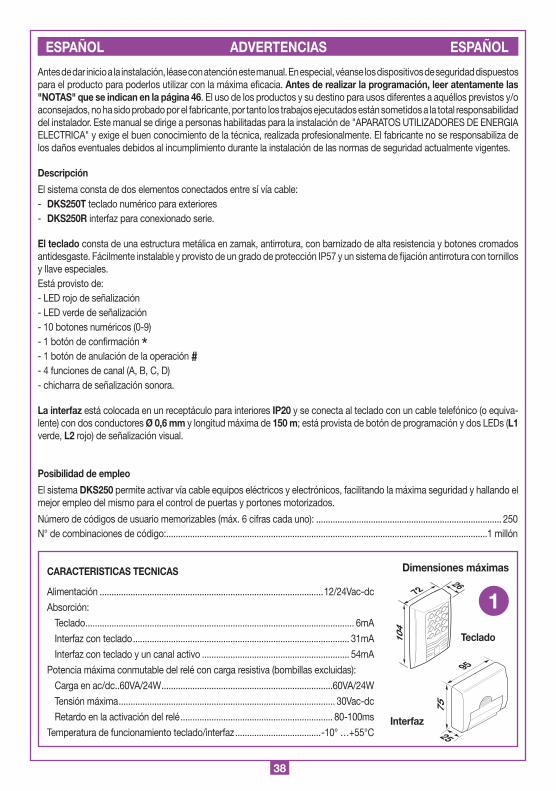
El teclado consta de una estructura metálica en zamak, antirrotura, con barnizado de alta resistencia y botones cromados antidesgaste. Fácilmente instalable y provisto de un grado de protección IP57 y un sistema de fijación antirrotura con tornillos y llave especiales.Está provisto de:- LED rojo de señalización- LED verde de señalización- 10 botones numéricos (0-9)- 1 botón de confirmación *- 1 botón de anulación de la operación #- 4 funciones de canal (A, B, C, D) - chicharra de señalización sonora.
La interfaz está colocada en un receptáculo para interiores IP20 y se conecta al teclado con un cable telefónico (o equiva-lente) con dos conductores Ø 0,6 mm y longitud máxima de 150 m; está provista de botón de programación y dos LEDs (L1 verde, L2 rojo) de señalización visual.
Posibilidad de empleo
El sistema DKS250 permite activar vía cable equipos eléctricos y electrónicos, facilitando la máxima seguridad y hallando el mejor empleo del mismo para el control de puertas y portones motorizados.
Número de códigos de usuario memorizables (máx. 6 cifras cada uno): .............................................................................. 250N° de combinaciones de código: .......................................................................................................................................1 millón
CARACTERISTICAS TECNICAS
Alimentación ..............................................................................................12/24Vac-dc
Absorción:
Teclado ................................................................................................................. 6mA
Interfaz con teclado ........................................................................................... 31mA
Interfaz con teclado y un canal activo .............................................................. 54mA
Potencia máxima conmutable del relé con carga resistiva (bombillas excluidas):
Carga en ac/dc..60VA/24W ........................................................................60VA/24W
Tensión máxima ........................................................................................... 30Vac-dc
Retardo en la activación del relé ................................................................ 80-100ms
Temperatura de funcionamiento teclado/interfaz ....................................-10° …+55°C
Dimensiones máximas
Interfaz
Teclado
1
39
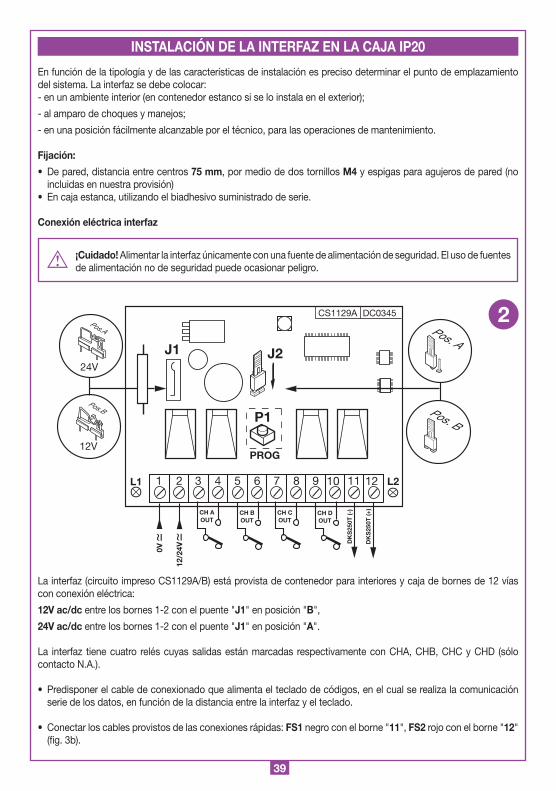
En función de la tipología y de las características de instalación es preciso determinar el punto de emplazamiento del sistema. La interfaz se debe colocar:- en un ambiente interior (en contenedor estanco si se lo instala en el exterior);
- al amparo de choques y manejos;
- en una posición fácilmente alcanzable por el técnico, para las operaciones de mantenimiento.
Fijación:
• De pared, distancia entre centros 75 mm, por medio de dos tornillos M4 y espigas para agujeros de pared (no incluidas en nuestra provisión)
• En caja estanca, utilizando el biadhesivo suministrado de serie.
Conexión eléctrica interfaz
¡Cuidado! Alimentar la interfaz únicamente con una fuente de alimentación de seguridad. El uso de fuentes de alimentación no de seguridad puede ocasionar peligro.
La interfaz (circuito impreso CS1129A/B) está provista de contenedor para interiores y caja de bornes de 12 vías con conexión eléctrica:
12V ac/dc entre los bornes 1-2 con el puente "J1" en posición "B",
24V ac/dc entre los bornes 1-2 con el puente "J1" en posición "A".
La interfaz tiene cuatro relés cuyas salidas están marcadas respectivamente con CHA, CHB, CHC y CHD (sólo contacto N.A.).
• Predisponer el cable de conexionado que alimenta el teclado de códigos, en el cual se realiza la comunicación serie de los datos, en función de la distancia entre la interfaz y el teclado.
• Conectar los cables provistos de las conexiones rápidas: FS1 negro con el borne "11", FS2 rojo con el borne "12" (fig. 3b).
CS1129A DC0345
J2
P1
PROG
24V
12V
Pos.A
Pos.B
J1
12/2
4V0V
1 2 3 4 5 6 7 8 9 10 11 12
CH BOUT
CH AOUT
CH DOUT
CH COUT
DK
S25
0T (-
)
DK
S25
0T (+
)
L1 L2
Interfaccia
DKS250R
28-11-2001
DC0345 Description :
Product Code :
Date :
Drawing number :
P.J.Heath
CARDIN ELETTRONICA S.p.A - 31020 San Vendemiano (TV) Italy - via Raffaello, 36 Tel: 0438/401818 Fax: 0438/401831
Draft :
All rights reserved. Unauthorised copying or use of the information contained in this document is punishable by law
DKS250R
Pos. A
Pos. B
2
INSTALACIÓN DE LA INTERFAZ EN LA CAJA IP20
40
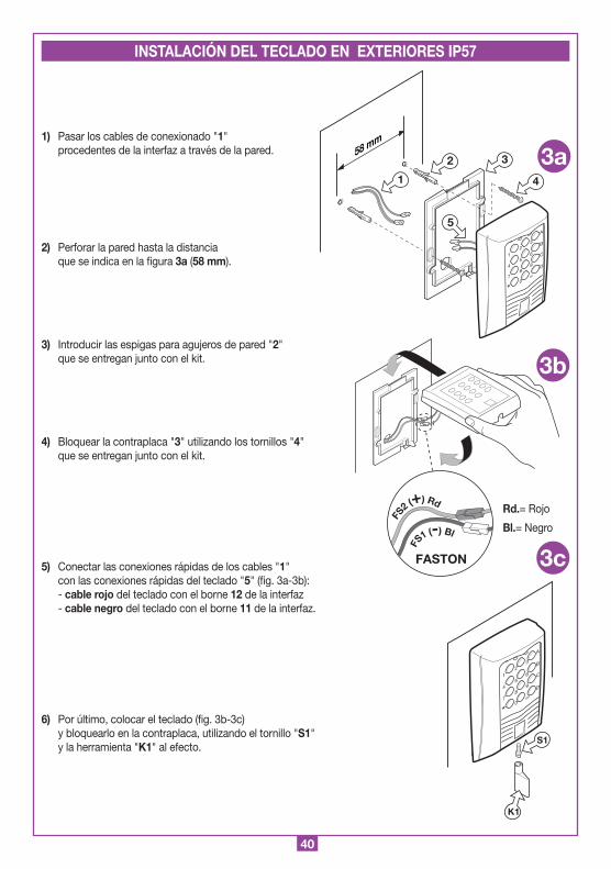
1) Pasar los cables de conexionado "1" procedentes de la interfaz a través de la pared.
2) Perforar la pared hasta la distancia que se indica en la figura 3a (58 mm).
3) Introducir las espigas para agujeros de pared "2" que se entregan junto con el kit.
4) Bloquear la contraplaca "3" utilizando los tornillos "4" que se entregan junto con el kit.
5) Conectar las conexiones rápidas de los cables "1" con las conexiones rápidas del teclado "5" (fig. 3a-3b): - cable rojo del teclado con el borne 12 de la interfaz - cable negro del teclado con el borne 11 de la interfaz.
6) Por último, colocar el teclado (fig. 3b-3c) y bloquearlo en la contraplaca, utilizando el tornillo "S1" y la herramienta "K1" al efecto.
A
1
2
5
8
0
3
6
94
7
*
B
C
D
Montaggio Tastiera DKS250T a superfice
DKS250T
28-11-2001
DM0557 Description :
Product Code :
Date :
Drawing number :
P.J.Heath
CARDIN ELETTRONICA S.p.A - 31020 San Vendemiano (TV) Italy - via Raffaello, 36 Tel: 0438/401818 Fax: 0438/401831
Draft :
All rights reserved. Unauthorised copying or use of the information contained in this document is punishable by law
58 mm
1
2 3
4
5
3a
Montaggio Tastiera DKS250T a superfice
DKS250T
04-03-2002
DM0670 Description :
Product Code :
Date :
Drawing number :
P.J.Heath
CARDIN ELETTRONICA S.p.A - 31020 San Vendemiano (TV) Italy - via Raffaello, 36 Tel: 0438/401818 Fax: 0438/401831
Draft :
All rights reserved. Unauthorised copying or use of the information contained in this document is punishable by law
FS
1 (-) Bl
FS
2 (+) Rd
FASTON
A
1
2
5
8
0
3
6
94
7
*
B
C
D
Montaggio Tastiera DKS250T a superfice
DKS250T
28-11-2001
DM0669 Description :
Product Code :
Date :
Drawing number :
P.J.Heath
CARDIN ELETTRONICA S.p.A - 31020 San Vendemiano (TV) Italy - via Raffaello, 36 Tel: 0438/401818 Fax: 0438/401831
Draft :
All rights reserved. Unauthorised copying or use of the information contained in this document is punishable by law
K1
S1
3b
3c
INSTALACIÓN DEL TECLADO EN EXTERIORES IP57
Rd.= Rojo
Bl.= Negro
41
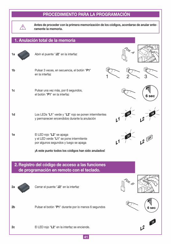
Antes de proceder con la primera memorización de los códigos, acordarse de anular ente-ramente la memoria.
1a Abrir el puente "J2" en la interfaz
1b Pulsar 3 veces, en secuencia, el botón "P1" en la interfaz
1c Pulsar una vez más, por 6 segundos, el botón "P1" en la interfaz
1d Los LEDs "L1" verde y "L2" rojo se ponen intermitentes y permanecen encendidos durante la anulación
1e El LED rojo "L2" se apaga y el LED verde "L1" se pone intermitente por algunos segundos y luego se apaga
¡A este punto todos los códigos han sido anulados!
2a Cerrar el puente "J2" en la interfaz
2b Pulsar el botón "P1" durante por lo menos 6 segundos
2c El LED rojo "L2" en la interfaz se enciende.
1 2 3
6 sec
L2ON
L1ON
L2OFF
L1ON
1. Anulación total de la memoria
PROCEDIMIENTO PARA LA PROGRAMACIÓN
Pos. A
2. Registro del código de acceso a las funciones de programación en remoto con el teclado.
6 sec
L2ON
Pos. B
42
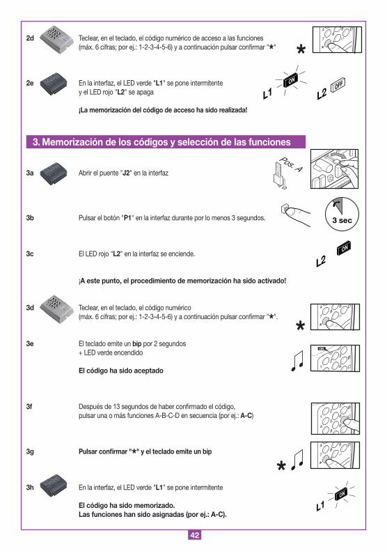
2d Teclear, en el teclado, el código numérico de acceso a las funciones (máx. 6 cifras; por ej.: 1-2-3-4-5-6) y a continuación pulsar confirmar "*"
2e En la interfaz, el LED verde "L1" se pone intermitente y el LED rojo "L2" se apaga
¡La memorización del código de acceso ha sido realizada!
3a Abrir el puente "J2" en la interfaz
3b Pulsar el botón "P1" en la interfaz durante por lo menos 3 segundos.
3c El LED rojo "L2" en la interfaz se enciende.
¡A este punto, el procedimiento de memorización ha sido activado!
3d Teclear, en el teclado, el código numérico (máx. 6 cifras; por ej.: 1-2-3-4-5-6) y a continuación pulsar confirmar "*".
3e El teclado emite un bip por 2 segundos + LED verde encendido
El código ha sido aceptado
3f Después de 13 segundos de haber confirmado el código, pulsar una o más funciones A-B-C-D en secuencia (por ej.: A-C)
3g Pulsar confirmar "*" y el teclado emite un bip
3h En la interfaz, el LED verde "L1" se pone intermitente El código ha sido memorizado. Las funciones han sido asignadas (por ej.: A-C).
8
0
94
7
*
D
1
23
6
B
C
ON
A
1
2
5
8
3
6
94
B
C
D
8
0
94
7
*
D
L1ON
*
8
0
94
7
*
D
L1ON
L2OFF
*
*
3. Memorización de los códigos y selección de las funciones
3 sec
L2ON
Pos. A

43
Si el "Registro del código de acceso a la programación en remoto" no ha sido realizado anteriormente, debe realizarse el procedimiento completo (ref. 2, pág. 41).
¡Atención! La memorización será posible sólo si el puente "J2" ha sido conectado
Si el "Registro del código de acceso a la programación en remoto" ha sido realizado:
4a Teclear, en el teclado, el código de acceso a la memorización y pulsar confirmar "*"
4b El teclado emite un bip y los LEDs rojo y verde se encienden (a continuación, el LED verde se apaga)
¡Función activada!
4c Teclear, en el teclado, el nuevo código numérico por memorizar (máx. 6 cifras; por ej. 1-2-3-4-5-6) y pulsar confirmar "*"
4d El teclado emite un bip por 2 segundos + LED verde encendido
El código ha sido aceptado y memorizado.
4e Después de 13 segundos de haber confirmado el código, pulsar una o más funciones A-B-C-D en secuencia (por ej.: A-C).
4f Pulsar confirmar "*" y el teclado emitirá un bip
Las funciones han sido asignadas (por ej.: A-C)
5a Abrir el puente "J2" en la interfaz
5b En la interfaz, pulsar el botón "P1" y a continuación soltarlo
MODALIDAD DE FUNCIONAMIENTO
4. Memorización de los códigos desde posición remota
*
*
8
0
94
7
*
D
8
0
94
7
*
D
1
23
6
B
C
ON
5. Anulación de un solo código
Pos. A
1
23
6
B
C
ON
A
1
2
5
8
3
6
94
B
C
D
8
0
94
7
*
D
*

44
5c En la interfaz, pulsar de nuevo el botón "P1" durante 3 segundos
5d En la interfaz, los LEDs verde "L1" y rojo "L2" se encienden
¡Dispositivo preparado para anular!
5e Teclear el código numérico por anular y pulsar confirmar "*"
5f En la interfaz, el LED verde "L1" se pone intermitente
¡Código anulado!
¡Atención! La anulación será posible sólo si el puente "J2" ha sido conectado
6a Teclear la siguiente secuencia #*(código para cancelar)*# (por ejemplo si se quiere cancelar el código 112233, marcar #*112233*#)
6b El teclado emite un bip por 2 segundos + LED verde y LED rojo encendidos
¡Código anulado!
3 sec
L2ON
L1ON
L1ON
*8
0
94
7
*
D
6. Anulación de un solo código desde posición remota
1
23
6
B
C
ON
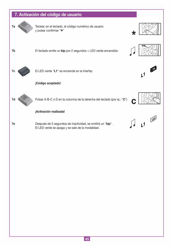
45
7a Teclear, en el teclado, el código numérico de usuario y pulsar confirmar "*"
7b El teclado emite un bip por 2 segundos + LED verde encendido
7c El LED verde "L1" se enciende en la interfaz
¡Código aceptado!
7d Pulsar A-B-C o D en la columna de la derecha del teclado (por ej.: "C")
¡Activación realizada!
7e Después de 5 segundos de inactividad, se emitirá un "bip". El LED verde se apaga y se sale de la modalidad.
7. Activación del código de usuario
L1ON
*8
0
94
7
*
D
1
23
6
B
C
ON
L1OFF
c1
5
8
6
94
B
C
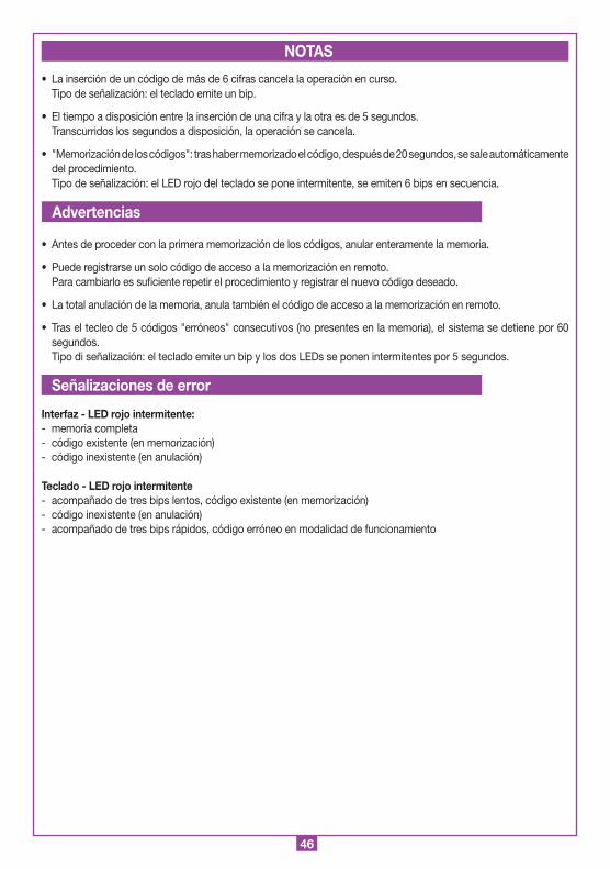
46
• La inserción de un código de más de 6 cifras cancela la operación en curso. Tipo de señalización: el teclado emite un bip.
• El tiempo a disposición entre la inserción de una cifra y la otra es de 5 segundos. Transcurridos los segundos a disposición, la operación se cancela.
• "Memorización de los códigos": tras haber memorizado el código, después de 20 segundos, se sale automáticamente del procedimiento.
Tipo de señalización: el LED rojo del teclado se pone intermitente, se emiten 6 bips en secuencia.
A
• Antes de proceder con la primera memorización de los códigos, anular enteramente la memoria.
• Puede registrarse un solo código de acceso a la memorización en remoto. Para cambiarlo es suficiente repetir el procedimiento y registrar el nuevo código deseado.
• La total anulación de la memoria, anula también el código de acceso a la memorización en remoto.
• Tras el tecleo de 5 códigos "erróneos" consecutivos (no presentes en la memoria), el sistema se detiene por 60 segundos.
Tipo di señalización: el teclado emite un bip y los dos LEDs se ponen intermitentes por 5 segundos.
Interfaz - LED rojo intermitente:- memoria completa- código existente (en memorización)- código inexistente (en anulación)
Teclado - LED rojo intermitente- acompañado de tres bips lentos, código existente (en memorización)- código inexistente (en anulación)- acompañado de tres bips rápidos, código erróneo en modalidad de funcionamiento
NOTAS
Advertencias
Señalizaciones de error

47
NOTE

48
CARDIN ELETTRONICA spa Via Raffaello, 36- 31020 San Vendemiano (TV) ItalyTel: +39/0438.404011-401818Fax: +39/0438.401831email (Italy): [email protected] (Europe): [email protected]: www.cardin.it