Embed Size (px)
Citation preview
1
Corrosion in the crude distillation unit overhead line: Contributors and solutions
Philipp SCHEMPP, Silvio KÖHLER, Marcus MENZEBACH, Karsten PREUSS, Micha TRÖGER
Shell Deutschland Oil GmbH, Godorfer Hauptstr. 150, 50997 Cologne, Germany,
[email protected], [email protected], [email protected],
[email protected], [email protected]
Abstract
This study is about corrosion found in the overhead line of a crude distillation tower. To understand the
reasons for the observed degradation and to derive appropriate conclusions, a comprehensive review of
all relevant parameters was conducted. The most important process parameters such as throughput, tem-
perature or dew-point and data from injection of neutralising and filming amines were recorded during
one year. Also, crude desalter efficiency and process water quality in the overhead accumulator vessel
(regarding pH, chlorides, ammonium and iron content) were considered. Furthermore, corrosion data
from ER probes (electrical resistance), UT sensors (ultrasonic testing) and weight-loss coupons was
analysed for the same period. The comparison of all parameters suggested corrosive amine salts as main
contributor to the observed corrosion where amine hydrochloride salts appear to be dominant. The in-
volvement of NH4Cl salts was predicted by a simple model to be unlikely. Also, the variation of the
neutralising amine injection rate did not influence pH significantly. Finally, a chloride limit for the
overhead system was calculated for the conditions present to limit the corrosion rate in carbon steel
equipment.
Keywords
Crude distillation unit, CDU overhead, ammonium salts, amine hydrochloride salts, HCl corrosion,
NH4Cl corrosion, corrosion inhibitor, neutralising amine, corrosion monitoring.
Introduction
Corrosion and/or fouling issues in the overhead system of crude distillation units (CDUs) are a
well-known and well-described phenomenon in the petrochemical industry. The most important
degradation mechanisms are 1) aqueous corrosion owing to hydrogen chloride that origins from
hydrolysis of inorganic chlorides in crude pre-heat and furnace, 2) corrosion due to ammonium
and/or hydrochloride salts that absorb moisture and start corrosion somewhere above the aque-
ous dew point, and 3) fouling of heat exchanger or air cooler tubes by such salts. Mitigation of
these degradation mechanisms always involves several parts of the unit (crude tanks, desalter,
injection points, overhead system etc.) and a combination of different approaches is needed
such as optimisation of the desalter performance, injection of chemical agents or dew point
control in the overhead system. This complexity makes an overhead system one of the most
vulnerable parts of each distillation unit. It also explains why corrosion/fouling in CDU over-
heads is still nowadays frequently observed, resulting in unplanned and expensive unit outages.
This study provides a comprehensive review of process, chemical and corrosion data gathered
during one year in one of three CDUs in Shell Rheinland Refinery. The conclusions suggestions
drawn from this analysis are currently realised in order to minimise the observed corrosion.
2
Background
1) Corrosion mechanisms
The most important corrosion mechanisms that can appear in the CDU overhead can be sum-
marised as follows:
• HCl corrosion: Corrosion due to dilution of HCl vapour into liquid water. Especially
the first water droplets formed during condensation can be very acidic and can provoke
localised but heavy corrosion at very low pH. HCl is mainly formed by hydrolysis of
naturally occurring inorganic chloride salts when crude oil is heated up in the pre-heat
train and in the CDU furnace. Most HCl is produced by heat-unstable salts such as
MgCl2 and CaCl2 that start to hydrolyse at much lower temperatures than e.g. NaCl
does. NaOH injection into crude oil helps to minimise salt hydrolysis, see below.
• Ammonium chloride (NH4Cl) corrosion: HCl tends to combine with NH3 to form am-
monium chloride (NH4Cl) [1]. NH3 can origin 1) from hydrocarbon streams that are
blended into crude oil, 2) from the desalter’s wash water that often comes from other
refinery units where NH3 is formed or 3) it is even injected intentionally into the CDU
overhead vapours to neutralise liquid HCl (i.e. for pH control). The re-sublimation of
solid NH4Cl salt depends upon the partial pressure of both HCl and NH3 vapours; the
product of these partial pressures is the Kp value. NH4Cl salts usually form above the
aqueous dew point and they remain dry and non-corrosive as long as the process tem-
perature is sufficiently above the dew point. A typical suggestion for this temperature
difference is minimum 20 to 25 Kelvin. The reason for this limit is that NH4Cl is very
hygroscopic and can absorb moisture, even if water has still not condensed [1]. If NH4Cl
salt deposits become wet, they can be very corrosive to many kinds of materials pro-
voking localised under-deposit corrosion. Also, excessive salt formation can cause foul-
ing, particularly in overhead heat exchangers and air coolers. Typical approaches to
prevent NH4Cl corrosion are 1) reduction of NH3 and HCl levels and thus salt formation
temperature by optimising the crude oil desalter and by adding NaOH, 2) temporary
water wash in the overhead line to remove salt deposits or even continuous water wash
to avoid salt deposition, 3) reduction of intentionally injected NH3 to a minimum and 4)
increase of the process temperature in the overhead line (if feasible from an economic
standpoint regarding product yields).
• Amine hydrochloride salt corrosion: HCl can also combine with amines to form hydro-
chloride salts that behave similarly to NH4Cl. Some hydrochloride salts can even be
liquid and thus corrode a larger surface [1]. Amines can origin 1) from amine solutions
that are injected into the overhead line for pH control as more effective alternative to
NH3, 2) from desalter wash water carry-over (as for NH4Cl), 3) from upstream facilities
where amines are frequently injected e.g. as H2S scavengers, and 4) from imported res-
idues or synthetic crude feedstocks that are used for blending and that can contain
amines from corrosion inhibition on other sites. Such amines that are brought from ex-
ternally into the refinery are often referred to as “tramp amines” [2].
• Wet H2S damage: Under wet conditions and if sufficient H2S is present, blistering and/or
cracking can occur, dependent upon water pH, cyanide content, plate metallurgy and
welding procedure (mainly regarding post-weld heat treatment). The different cracking
mechanisms will not be discussed further in this study, which focuses on corrosion due
to HCl and salts.
3
2) Minimisation of overhead corrosion
The most common approaches to generally minimise the above-mentioned corrosion mecha-
nisms are as follows [3]:
• Blending: One of the most common techniques for corrosion control is blending corro-
sive crudes with less-corrosive crudes, dependent upon refinery configuration and crude
flexibility.
• Crude oil de-watering: Most salts are diluted in the water phase why the crude oil’s
water content should be minimised, e.g. by draining crude oil storage tanks. A typical
H2O limit for desalted crude oil is max. 0.5 wt.-%.
• Crude oil desalting: Crude oil is mixed with wash water to remove most of inorganic
contaminants (e.g. salts) and solids, typically at temperatures between 100 and 150°C
and water contents of approx. 5 vol.-%, including injection of chemicals such as de-
emulsifiers to avoid emulsion formation or chemicals to control pH of the desalter wa-
ter. Oil and water phase are separated in the desalter where most salts and sediments
leave the vessel together with the water phase.
• Caustic injection: To minimise hydrolysis and thus HCl in the overhead. Diluted NaOH
is typically dosed into crude oil downstream of the desalter. Caustic will then convert
most of the unstable chloride salts (such as MgCl2 and CaCl2) and/or already formed
HCl into NaCl that leaves the distillation column through the bottom. The exact mech-
anism of how NaOH reacts with chlorides is still under debate [1].
• Injection of chemical agents: NH3 or amines are often used to neutralise HCl and to
control pH in the condensing water phase by e.g. injecting them into the overhead va-
pour. Note that, as indicated above, amines such as e.g. ethylene diamine (EDA) or
monoethanolamine (MEA) are more effective in stabilising the pH of the first water
drops condensing. The disadvantage of ammonia (NH3) is that it dissolves into water
much slower than HCl and most amines do [4]. Hence, NH3 has a comparably poor
ability to influence pH at the point of first condensation. Typical pH limits are 5.5 to 6.5
to avoid increased corrosion at lower pH and salt formation (and possibly fouling) at
higher pH. Also, organic corrosion inhibitors are injected to reduce corrosion. They are
commonly called “filmers” as they attach to the internal surface protecting it to some
degree from corrosion by acidic solutions.
• Water washing: As mentioned above, water washing is an important tool to 1) dilute
low pH water phases at dew point conditions and to 2) wash out salts from overhead
piping and heat exchangers / air coolers.
• Materials selection: The application of CRAs (corrosion resistant alloys) is restricted,
due to chlorides present, mostly to ferritic steel, (super-) duplex steel or (comparably
expensive) Ni base alloys. For this reason, unalloyed carbon steel is still likely the most
common material used in CDU overhead piping and vessels.
Procedure
This study is about one of three crude distillation units that exist in Shell Rheinland Refinery.
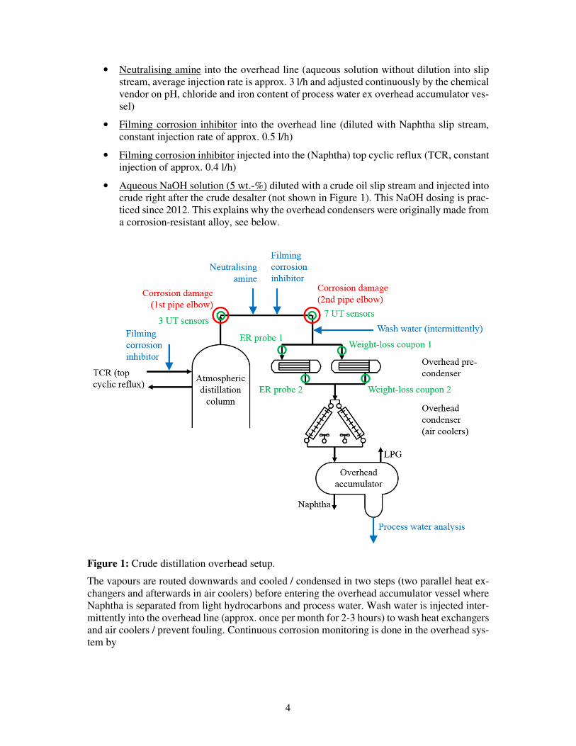
The corresponding CDU has a one-step overhead system as shown by Figure 1. The overhead
vapours leave the atmospheric distillation column over the top. In the following horizontal part
of the DN 800 overhead line there are injected two chemical agents, both via a typical injection
quill. Four chemicals are injected via an injection quill on different locations:
4
• Neutralising amine into the overhead line (aqueous solution without dilution into slip
stream, average injection rate is approx. 3 l/h and adjusted continuously by the chemical
vendor on pH, chloride and iron content of process water ex overhead accumulator ves-
sel)
• Filming corrosion inhibitor into the overhead line (diluted with Naphtha slip stream,
constant injection rate of approx. 0.5 l/h)
• Filming corrosion inhibitor injected into the (Naphtha) top cyclic reflux (TCR, constant
injection of approx. 0.4 l/h)
• Aqueous NaOH solution (5 wt.-%) diluted with a crude oil slip stream and injected into
crude right after the crude desalter (not shown in Figure 1). This NaOH dosing is prac-
ticed since 2012. This explains why the overhead condensers were originally made from
a corrosion-resistant alloy, see below.
Figure 1: Crude distillation overhead setup.
The vapours are routed downwards and cooled / condensed in two steps (two parallel heat ex-
changers and afterwards in air coolers) before entering the overhead accumulator vessel where
Naphtha is separated from light hydrocarbons and process water. Wash water is injected inter-
mittently into the overhead line (approx. once per month for 2-3 hours) to wash heat exchangers
and air coolers / prevent fouling. Continuous corrosion monitoring is done in the overhead sys-
tem by
5
• 2 intrusive electrical resistance (ER) probes that determine online a corrosion rate. They
are installed upstream and downstream of one heat exchanger to monitor corrosion un-
der dry conditions (upstream) and after partial condensation (downstream).
• 2 intrusive weight-loss coupons in a similar position close to the other heat exchanger.
They are removed /renewed every approx. 3-4 months
• 10 wireless Permasense® UT (ultrasonic testing) sensors that measure twice a day local
wall thickness on the first and on the second elbow, see Figure 2. Sensor installation
and technique are described in detail elsewhere [5].
Most piping and vessels located in the overhead system are made from (unalloyed) carbon steel,
including ER probes and weight-loss coupons. Only the air cooler tubes as well as the header
boxes are made of the super-austenitic alloy 904 L. Furthermore, one of two heat exchanger
bundles was upgraded recently from carbon steel to Alloy 59 (NiCrMo). Overhead line and heat
exchangers suffered increased corrosion in the past. Accordingly, parts of the overhead line
such as nozzles (where salt deposition and water condensation are more likely) had to be re-
placed due to increased wall thinning. Also, both heat exchanger bundles are designed to be
replaced regularly due to water condensation that initiates in these bundles. Severe pitting cor-
rosion and scaling on the external surface of the tube bundles and in the bottom of the shell
seems to be most likely caused by corrosive salts.
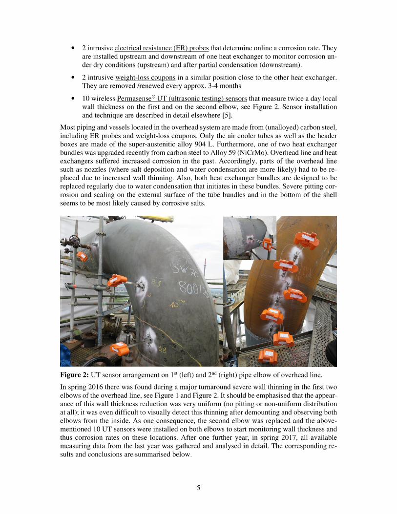
Figure 2: UT sensor arrangement on 1st (left) and 2nd (right) pipe elbow of overhead line.
In spring 2016 there was found during a major turnaround severe wall thinning in the first two
elbows of the overhead line, see Figure 1 and Figure 2. It should be emphasised that the appear-
ance of this wall thickness reduction was very uniform (no pitting or non-uniform distribution
at all); it was even difficult to visually detect this thinning after demounting and observing both
elbows from the inside. As one consequence, the second elbow was replaced and the above-
mentioned 10 UT sensors were installed on both elbows to start monitoring wall thickness and
thus corrosion rates on these locations. After one further year, in spring 2017, all available
measuring data from the last year was gathered and analysed in detail. The corresponding re-
sults and conclusions are summarised below.
6
Results and Discussion
1) UT sensor measurements
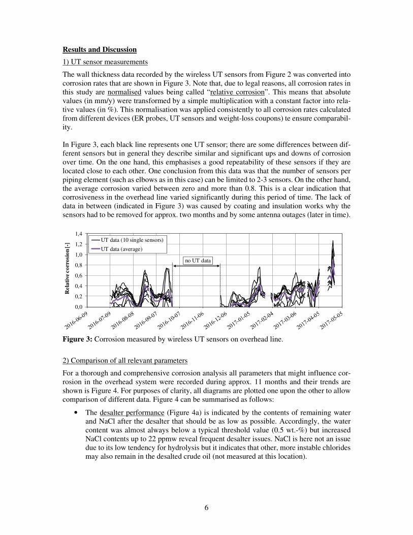
The wall thickness data recorded by the wireless UT sensors from Figure 2 was converted into
corrosion rates that are shown in Figure 3. Note that, due to legal reasons, all corrosion rates in
this study are normalised values being called “relative corrosion”. This means that absolute
values (in mm/y) were transformed by a simple multiplication with a constant factor into rela-
tive values (in %). This normalisation was applied consistently to all corrosion rates calculated
from different devices (ER probes, UT sensors and weight-loss coupons) te ensure comparabil-
ity.
In Figure 3, each black line represents one UT sensor; there are some differences between dif-
ferent sensors but in general they describe similar and significant ups and downs of corrosion
over time. On the one hand, this emphasises a good repeatability of these sensors if they are
located close to each other. One conclusion from this data was that the number of sensors per
piping element (such as elbows as in this case) can be limited to 2-3 sensors. On the other hand,
the average corrosion varied between zero and more than 0.8. This is a clear indication that
corrosiveness in the overhead line varied significantly during this period of time. The lack of
data in between (indicated in Figure 3) was caused by coating and insulation works why the
sensors had to be removed for approx. two months and by some antenna outages (later in time).
Figure 3: Corrosion measured by wireless UT sensors on overhead line.
2) Comparison of all relevant parameters
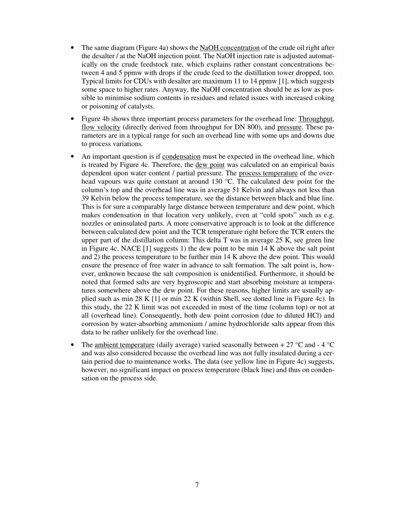
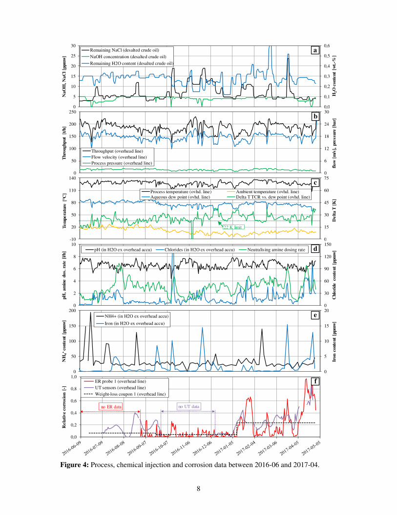
For a thorough and comprehensive corrosion analysis all parameters that might influence cor-
rosion in the overhead system were recorded during approx. 11 months and their trends are
shown is Figure 4. For purposes of clarity, all diagrams are plotted one upon the other to allow
comparison of different data. Figure 4 can be summarised as follows:
• The desalter performance (Figure 4a) is indicated by the contents of remaining water
and NaCl after the desalter that should be as low as possible. Accordingly, the water
content was almost always below a typical threshold value (0.5 wt.-%) but increased
NaCl contents up to 22 ppmw reveal frequent desalter issues. NaCl is here not an issue
due to its low tendency for hydrolysis but it indicates that other, more instable chlorides
may also remain in the desalted crude oil (not measured at this location).
0,0
0,2
0,4
0,6
0,8
1,0
1,2
1,4
Rel
ativ
e co
rros
ion
[-] UT data (10 single sensors)
UT data (average)
no UT data
7
• The same diagram (Figure 4a) shows the NaOH concentration of the crude oil right after
the desalter / at the NaOH injection point. The NaOH injection rate is adjusted automat-
ically on the crude feedstock rate, which explains rather constant concentrations be-
tween 4 and 5 ppmw with drops if the crude feed to the distillation tower dropped, too.
Typical limits for CDUs with desalter are maximum 11 to 14 ppmw [1], which suggests
some space to higher rates. Anyway, the NaOH concentration should be as low as pos-
sible to minimise sodium contents in residues and related issues with increased coking
or poisoning of catalysts.
• Figure 4b shows three important process parameters for the overhead line: Throughput,
flow velocity (directly derived from throughput for DN 800), and pressure. These pa-
rameters are in a typical range for such an overhead line with some ups and downs due
to process variations.
• An important question is if condensation must be expected in the overhead line, which
is treated by Figure 4c. Therefore, the dew point was calculated on an empirical basis
dependent upon water content / partial pressure. The process temperature of the over-
head vapours was quite constant at around 130 °C. The calculated dew point for the
column’s top and the overhead line was in average 51 Kelvin and always not less than
39 Kelvin below the process temperature, see the distance between black and blue line.
This is for sure a comparably large distance between temperature and dew point, which
makes condensation in that location very unlikely, even at “cold spots” such as e.g.
nozzles or uninsulated parts. A more conservative approach is to look at the difference
between calculated dew point and the TCR temperature right before the TCR enters the
upper part of the distillation column: This delta T was in average 25 K, see green line
in Figure 4c. NACE [1] suggests 1) the dew point to be min 14 K above the salt point
and 2) the process temperature to be further min 14 K above the dew point. This would
ensure the presence of free water in advance to salt formation. The salt point is, how-
ever, unknown because the salt composition is unidentified. Furthermore, it should be
noted that formed salts are very hygroscopic and start absorbing moisture at tempera-
tures somewhere above the dew point. For these reasons, higher limits are usually ap-
plied such as min 28 K [1] or min 22 K (within Shell, see dotted line in Figure 4c). In
this study, the 22 K limit was not exceeded in most of the time (column top) or not at
all (overhead line). Consequently, both dew point corrosion (due to diluted HCl) and
corrosion by water-absorbing ammonium / amine hydrochloride salts appear from this
data to be rather unlikely for the overhead line.
• The ambient temperature (daily average) varied seasonally between + 27 °C and - 4 °C
and was also considered because the overhead line was not fully insulated during a cer-
tain period due to maintenance works. The data (see yellow line in Figure 4c) suggests,
however, no significant impact on process temperature (black line) and thus on conden-
sation on the process side.
8
Figure 4: Process, chemical injection and corrosion data between 2016-06 and 2017-04.
0,0
0,1
0,2
0,3
0,4
0,5
0,6
0
5
10
15
20
25
30
H2O
con
tent
[w
t.-%
]
NaO
H, N
aCl
[ppm
w]
Remaining NaCl (desalted crude oil)
NaOH concentration (desalted crude oil)
Remaining H2O content (desalted crude oil)
a
0
6
12
18
24
30
0
50
100
150
200
250
flow
[m
/s],
pre
ssur
e [b
ar]
Thr
ough
put
[t
/h]
Throughput (overhead line)
Flow velocity (overhead line)
Process pressure (overhead line)
b
0
15
30
45
60
75
-10
20
50
80
110
140
Del
ta T
[K
]
Tem
pera
ture
[°C
] Process temperature (ovhd. line) Ambient temperature (ovhd. line)
Aqueous dew point (ovhd. line) Delta T TCR vs. dew point (ovhd. line)
22 K limit
c
0
30
60
90
120
150
0
2
4
6
8
10
Chl
orid
e co
nten
t [p
pmw
]
pH,
amin
e do
s. r
ate
[l/h
] pH (in H2O ex overhead accu) Chlorides (in H2O ex overhead accu) Neutralising amine dosing rate d
0
5
10
15
20
0
50
100
150
200
Iron
con
tent
[pp
mw
]
NH
4+
cont
ent
[ppm
w]
NH4+ (in H2O ex overhead accu)
Iron (in H2O ex overhead accu)
e
0,0
0,2
0,4
0,6
0,8
1,0
Rel
ativ
e co
rros
ion
[-]
ER probe 1 (overhead line)
UT sensors (overhead line)
Weight-loss coupon 1 (overhead line)
no UT datano ER data
f
9
• Very important to check is, of course, the process water quality from the overhead ac-
cumulator, see Figure 4d. The often-used chloride limit of max 10 ppmw was exceeded
in 60% of the time with 5 peaks at even > 50 ppmw. The average chloride content was
18 ppmw, which clearly suggests increased corrosion, particularly for the carbon steel
equipment. Interestingly, the corresponding pH (black line) was in average 6.6, being
in 44% of the time within the typical range (5,5 to 6,5), only few times (2%) too low,
but many times (54%) too high with peaks up to 8. High chloride levels together with
increased pH can be explained by the following hypothesis: HCl vapours are not diluted
in the water phase (to immediately form aggressive hydrochloric acid) since there is no
liquid water in the overhead line due to the large distance between process temperature
and dew point, see above. Hence, the gaseous HCl present might react (at least partially)
with (tramp) amines to form hydrochloride salts. The formation of pH-decreasing salts
(when being diluted in water during condensation) such as e.g. NH4Cl seems to be un-
probable because of the comparably high pH during the year. Further reasons for ele-
vated pH can be excessive NaOH and/or amine dosing.
• The intention for adding neutralising amine into the overhead line is to limit the water
pH to a minimum, which again limits the corrosion rate. Consequently, the above-men-
tioned comparably high pH values either a) challenge the need for neutralising amine
or b) even indicate overdosing of neutralising amine and/or filmers (that generally in-
crease pH). Furthermore, the actual amine dosing rate was varied significantly over time
(see green curve in Figure 4d, in average 2.9 l/h); but it does not seem to have a large
influence on the water pH in the overhead accumulator. This is discussed further below.
• The filming amine corrosion inhibitors used in TCR and overhead line are further
sources of amines for possible reactions with HCl to form amine and/or amine hydro-
chloride salts. However, they usually tend to be less reactive with HCl than neutralising
amines owing to their different chemical composition [1].
• Two further parameters are measured twice a week in the water phase from the overhead
vessel, see Figure 4e: Ammonium (NH4+) that reflects the salt formation potential but it
also includes all injected amines, which makes interpretation difficult. Moreover, the
iron content is determined to check for active corrosion. Both parameters reveal sharp
peaks that coincide rather well with chlorides in desalted crude oil and chloride peaks
measured in the same water phase. The observed average ammonium content (34
ppmw) is argued to be in a typical range for CDU overhead systems [6] whereas the
average Fe content (1,5 ppmw) was comparably low. Low Fe contents together with
increased corrosion rates suggest more localised than generalised corrosion.
• The corrosion measuring data from all three techniques is shown by Figure 4f. Note that
from both ER probes and weight-loss coupons only data from the probes upstream of
the pre-condenser is considered for purposes of comparison. The measuring data looks
very similar: All techniques reveal an increased tendency for corrosion during the whole
period, even the weight-loss coupons with their very low “measuring frequency” (ap-
prox. 3.5 months) compared to ER and UT probes. Furthermore, single peaks in corro-
sion coincide quite well for ER and UT probes, which confirms both techniques as ap-
propriate techniques for corrosion monitoring in such a CDU overhead system. Inter-
estingly, ER probe 1 shows a higher variation in corrosion and seems thus to be more
sensitive than UT wall thickness sensors; on the other hand, ER data seems to be “de-
layed” by approx. 5 days. The reasons for this different behaviour might be linked to
the different location: ER probes are intrusive and located in the centre of the pipe
whereas UT sensors detect corrosion / wall thinning directly on the internal pipe surface.
10
Note that the sensitivity of the wireless wall thickness sensors used in this study is com-
parably high at approx. ± 0.01 mm [5]. Moreover, the process conditions should be
similar at both locations. Also, it was found a rather clear correlation of corrosion data
with the chloride content of the water phase from the overhead accumulator (Figure 4d).
This finding is discussed further in the next section.
The data further showed that wash water injected intermittently did not have any noticeable
effect on the data presented in Figure 4.
3) Further discussion
a) Neutralising amine dosing
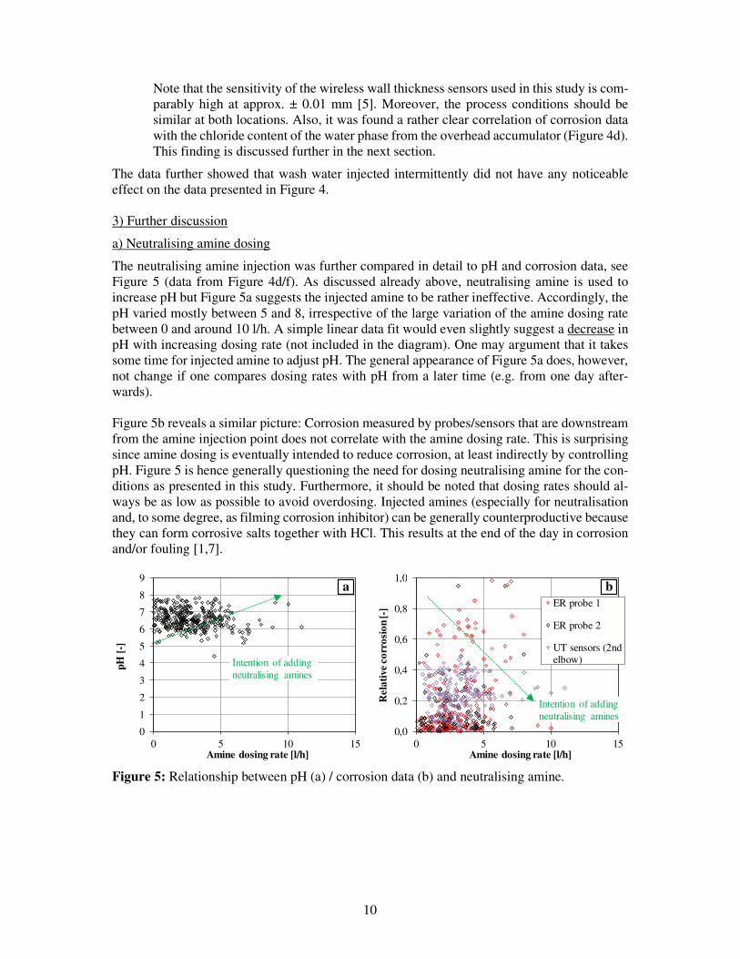
The neutralising amine injection was further compared in detail to pH and corrosion data, see
Figure 5 (data from Figure 4d/f). As discussed already above, neutralising amine is used to
increase pH but Figure 5a suggests the injected amine to be rather ineffective. Accordingly, the
pH varied mostly between 5 and 8, irrespective of the large variation of the amine dosing rate
between 0 and around 10 l/h. A simple linear data fit would even slightly suggest a decrease in
pH with increasing dosing rate (not included in the diagram). One may argument that it takes
some time for injected amine to adjust pH. The general appearance of Figure 5a does, however,
not change if one compares dosing rates with pH from a later time (e.g. from one day after-
wards).
Figure 5b reveals a similar picture: Corrosion measured by probes/sensors that are downstream
from the amine injection point does not correlate with the amine dosing rate. This is surprising
since amine dosing is eventually intended to reduce corrosion, at least indirectly by controlling
pH. Figure 5 is hence generally questioning the need for dosing neutralising amine for the con-
ditions as presented in this study. Furthermore, it should be noted that dosing rates should al-
ways be as low as possible to avoid overdosing. Injected amines (especially for neutralisation
and, to some degree, as filming corrosion inhibitor) can be generally counterproductive because
they can form corrosive salts together with HCl. This results at the end of the day in corrosion
and/or fouling [1,7].
Figure 5: Relationship between pH (a) / corrosion data (b) and neutralising amine.
0
1
2
3
4
5
6
7
8
9
0 5 10 15
pH [
-]
Amine dosing rate [l/h]
Intention of adding
neutralising amines
a
0,0
0,2
0,4
0,6
0,8
1,0
0 5 10 15
Rel
ativ
e co
rros
ion
[-]
Amine dosing rate [l/h]
ER probe 1
ER probe 2
UT sensors (2ndelbow)
Intention of adding
neutralising amines
b
11
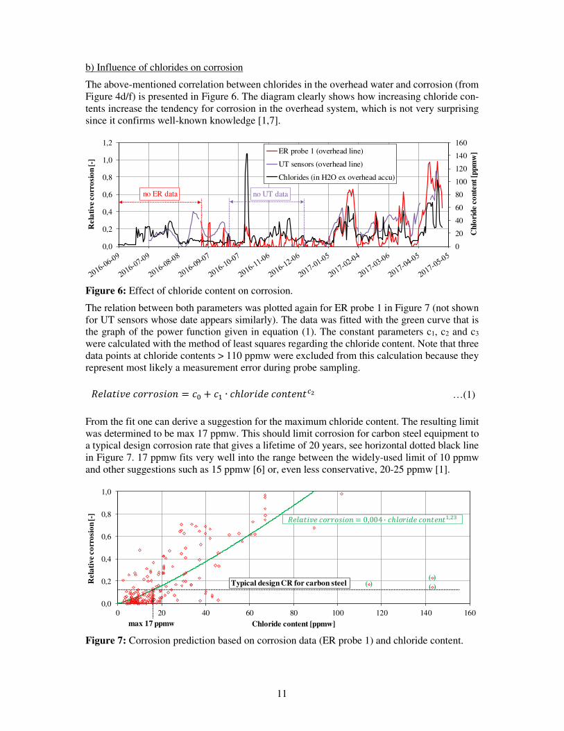
b) Influence of chlorides on corrosion
The above-mentioned correlation between chlorides in the overhead water and corrosion (from
Figure 4d/f) is presented in Figure 6. The diagram clearly shows how increasing chloride con-
tents increase the tendency for corrosion in the overhead system, which is not very surprising
since it confirms well-known knowledge [1,7].
Figure 6: Effect of chloride content on corrosion.
The relation between both parameters was plotted again for ER probe 1 in Figure 7 (not shown
for UT sensors whose date appears similarly). The data was fitted with the green curve that is
the graph of the power function given in equation (1). The constant parameters c1, c2 and c3
were calculated with the method of least squares regarding the chloride content. Note that three
data points at chloride contents > 110 ppmw were excluded from this calculation because they
represent most likely a measurement error during probe sampling.
…(1)
From the fit one can derive a suggestion for the maximum chloride content. The resulting limit
was determined to be max 17 ppmw. This should limit corrosion for carbon steel equipment to
a typical design corrosion rate that gives a lifetime of 20 years, see horizontal dotted black line
in Figure 7. 17 ppmw fits very well into the range between the widely-used limit of 10 ppmw
and other suggestions such as 15 ppmw [6] or, even less conservative, 20-25 ppmw [1].
Figure 7: Corrosion prediction based on corrosion data (ER probe 1) and chloride content.
0
20
40
60
80
100
120
140
160
0,0
0,2
0,4
0,6
0,8
1,0
1,2
Chl
orid
e co
nten
t [pp
mw
]
Rel
ativ
e co
rros
ion
[-]
ER probe 1 (overhead line)
UT sensors (overhead line)
Chlorides (in H2O ex overhead accu)
no UT datano ER data
0,0
0,2
0,4
0,6
0,8
1,0
0 20 40 60 80 100 120 140 160
Rel
ativ
e co
rros
ion
[-]
Chloride content [ppmw]
Typical design CR for carbon steel
max 17 ppmw
( )
������������ � 0,004 · ������ �� ��,��
( )( )
������������ � � + � ∙ ������ �� ���
12
Note that the empirical corrosion prediction from measurements of 1) corrosion and 2) chloride
content in the overhead process water does not consider at all in which form the chlorides are
present when corrosion starts. Also, consider that it represents the process conditions as repre-
sented for the CDU overhead of this study.
c) Prediction of NH4Cl salt formation
One uncertainty remains the question which salts form in the overhead system presented in this
study. This question cannot be answered easily since the composition of salt forming amines
present is unknown, too. Nevertheless, one typical salt that is usually expected in CDU over-
head systems and that is suggested as main contributor to corrosion is ammonium chloride
(NH4Cl) [1]. The related corrosion mechanism was outlined in the background section above.
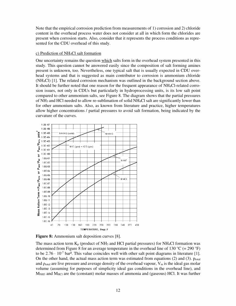
It should be further noted that one reason for the frequent appearance of NH4Cl-related corro-
sion issues, not only in CDUs but particularly in hydroprocessing units, is its low salt point
compared to other ammonium salts, see Figure 8. The diagram shows that the partial pressures
of NH3 and HCl needed to allow re-sublimation of solid NH4Cl salt are significantly lower than
for other ammonium salts. Also, as known from literature and practice, higher temperatures
allow higher concentrations / partial pressures to avoid salt formation, being indicated by the
curvature of the curves.
Figure 8: Ammonium salt deposition curves [8].
The mass action term Kp (product of NH3 and HCl partial pressures) for NH4Cl formation was
determined from Figure 8 for an average temperature in the overhead line of 130 °C (= 290 °F)
to be 2.76 · 10-7 bar². This value coincides well with other salt point diagrams in literature [1].
On the other hand, the actual mass action term was estimated from equations (2) and (3). ptotal
and ρtotal are live pressure and average density of the overhead vapour, Vm is the ideal gas molar
volume (assuming for purposes of simplicity ideal gas conditions in the overhead line), and
MNH3 and MHCl are the (constant) molar masses of ammonia and (gaseous) HCl. It was further
13
assumed that ammonia (NH3) is diluted in the accumulator’s water phase to fully form ammo-
nium ions (NH4+). For purposes of simplicity, the NH4
+ content was assumed to be the average
value from above (34 ppmw, recall Figure 4e) because NH4+ was determined only twice per
week. The chloride content in equation (3) comes from daily live values, see the results above
(Figure 4d). All constant parameters are summarised in Table 1.
…(2)
…(3)
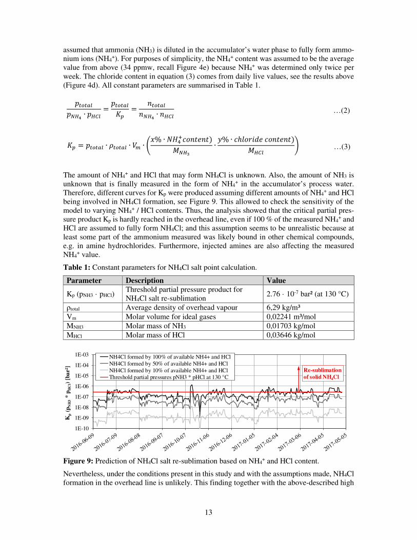
The amount of NH4+ and HCl that may form NH4Cl is unknown. Also, the amount of NH3 is
unknown that is finally measured in the form of NH4+ in the accumulator’s process water.
Therefore, different curves for Kp were produced assuming different amounts of NH4+ and HCl
being involved in NH4Cl formation, see Figure 9. This allowed to check the sensitivity of the
model to varying NH4+ / HCl contents. Thus, the analysis showed that the critical partial pres-
sure product Kp is hardly reached in the overhead line, even if 100 % of the measured NH4+ and
HCl are assumed to fully form NH4Cl; and this assumption seems to be unrealistic because at
least some part of the ammonium measured was likely bound in other chemical compounds,
e.g. in amine hydrochlorides. Furthermore, injected amines are also affecting the measured
NH4+ value.
Table 1: Constant parameters for NH4Cl salt point calculation.
Parameter Description Value
Kp (pNH3 · pHCl) Threshold partial pressure product for
NH4Cl salt re-sublimation 2.76 · 10-7 bar² (at 130 °C)
ρtotal Average density of overhead vapour 6,29 kg/m³
Vm Molar volume for ideal gases 0,02241 m³/mol
MNH3 Molar mass of NH3 0,01703 kg/mol
MHCl Molar mass of HCl 0,03646 kg/mol
Figure 9: Prediction of NH4Cl salt re-sublimation based on NH4+ and HCl content.
Nevertheless, under the conditions present in this study and with the assumptions made, NH4Cl
formation in the overhead line is unlikely. This finding together with the above-described high
1E-10
1E-09
1E-08
1E-07
1E-06
1E-05
1E-04
1E-03
Kp
(pN
H3
* p H
Cl)
[bar
²]
NH4Cl formed by 100% of available NH4+ and HCl
NH4Cl formed by 50% of available NH4+ and HCl
NH4Cl formed by 10% of available NH4+ and HCl
Threshold partial pressures pNH3 * pHCl at 130 °C
Re-sublimation of solid NH4Cl
���� !�"#$ ∙ �#%! ����� !&' � ��� ! "#$ ∙ #%!
&' � ���� ! ∙ (��� ! ∙ )* ∙ +,% ∙ ./01 �� �)3"#4∙ 5% ∙ ������ �� �)
3#%! 6
14
chloride – high pH observation leads to the following conclusion: Both (aqueous) HCl and
NH4Cl corrosion seem to be of secondary importance. Instead, corrosion by amine hydrochlo-
ride salts can be carefully suggested as main contributor to the observed, increased corrosion in
overhead line and heat exchangers. The above, described very uniform wall thinning in the first
two elbows of the overhead line further suggests liquid amine hydrochlorides as main contrib-
utor.
Conclusions and suggestions
The following conclusions can be derived step by step from the results and for the process
conditions presented above:
• Dew point corrosion was found to be unlikely in the CDU overhead line owing to a
comparably large distance of (in average) 25 K between process and TCR temperature.
• Aqueous HCl corrosion in the overhead line is hence unlikely, too. This is supported by
the comparably high water pH. It further increases the probability that the corrosion
observed was primarily caused by ammonium and/or hydrochloride amine salts.
• Measured corrosion (by ER probes, UT sensors and weight-loss coupons) revealed a
clear correlation between chloride content and corrosion rate.
• An empirical limit of max 17 ppmw was defined for the process conditions present in
this study to keep corrosion in carbon steel equipment below a design corrosion rate that
allows 20 years of lifetime.
• A simple model predicted the NH3 and HCl partial pressures present as too low to form
significant amounts of NH4Cl. Thus, NH4Cl as well-known corrosion contributor can
be mostly excluded from the group of possibly contributing ammonium / amine hydro-
chloride salts.
• These findings and the recent corrosion appearance in the overhead line`s first two el-
bows (very uniform, no localised pitting) suggest liquid hydrochloride amine salts as
one likely reason for the degradation found. Such compounds work as electrolytes pro-
moting electrochemical corrosion without the need for liquid water.
Further conclusions are:
• The origin of liquid hydrochloride amine salts is unclear. Possible origins range from
the crude oil diet itself over tramp amines from e.g. blended residues or condensates to
the chemicals injected (amines and NaOH).
• The neutralising amine injection rate varied significantly over time being adjusted on
measuring values from the overhead process water. The injected amine showed, how-
ever, no impact on pH that is actually intended to be controlled by the injection. Also,
corrosion was not reduced by the injected amine.
These conclusions lead to the following suggestions:
• The 4 injected chemicals (NaOH, neutralising amine and both amine filming inhibitors)
should be checked in a parameter study for their influence on the particular parameter
that they are designed for to control. On this basis, each injection should be reduced
carefully to a minimum necessary. Switching to other amines can also be a reasonable
option. The (possibly positive) impact of NaOH on the (suggested) formation of liquid
hydrochlorides should be checked separately by a comparison of NaOH injection vs.
corrosion data during a certain period.
15
• Computer modelling / ionic modelling should be applied to calculate more reliably salt
formation temperatures. This will also provide 1) water condensation rates and 2) salt
deposition rates as further corrosion indicators.
• The refinery`s crude oil diet (including distillation into side streams) should be analysed
for nitrogen levels as rough indicator for nitrogen compounds such as ammonia or
amines.
• The planned extension of the above-described CDU by replacing the currently used
flash vessel by a pre-flash fractionating column should be realised and would relieve
the current CDU overhead system.
• The number of (Permasense®) UT wireless wall thickness sensors can be reduced to
approx. 3 sensors per pipe elbow to have a sufficiently high repeatability, even on pipes
with large diameters such as DN 800 as described in this study.
Acknowledgements
The authors would like to thank the chemical vendor for their support. Also, support and fruitful
discussions with Martien Tazelaar (Shell P&T) and colleagues from Rheinland Refinery are
greatly appreciated.
References
[1] N.N., “Crude Distillation Unit – Distillation Tower Overhead System Corrosion”, NACE
International Publication 34109 (Task Group 342), NACE International, Houston, USA
(2009).
[2] R. Rechtien and G. Duggan, “Identifying the Impacts of Amine Contamination on Crude
Units”, CORROSION Conference, paper no. 06851, NACE International, Houston,
USA (2006).
[3] N.N., “Corrosion Control in the Refining Industry Course Manual”, Chapter 2: “Crude
Distillation and Desalting”, NACE International, Houston, USA (2007).
[4] V. Braden, P. Petersen, M. Malpiedi, L. Bowerbank and J. Gorman, „Crude Unit Over-
head Corrosion Control“, CORROSION Conference, paper no. 98585, NACE Interna-
tional, Houston, USA (1998).
[5] P. Schempp, K. Preuß and M. Troeger, “About the Correlation Between Crude Oil Cor-
rosiveness and Results From Corrosion Monitoring in an Oil Refinery” Corrosion, 72
(2016) 843-855.
[6] P. Thornthwaite and J. Davies, “Monitoring and simulation resolves overhead corro-
sion”, PTQ, Q1 (2016) 53-63.
[7] B. Chambers, K. Yap, S. Srinivasan and M. Yunovich, “Corrosion in Crude Distillation
Unit Overhead Operations: A comprehensive review”, CORROSION Conference, paper
no. 11360, NACE International, Houston, USA (2011).
[8] P. Chueh, “Phase and Ionic Equilibria of the System HF/H2S/NH3/H2/H2O at High
Temperatures and Pressures”, ERC TPR, pp. 52-69.


![Hochintegrale Oberschale und M³F-Vorderkante eines CFK ... · -„Brent crude oil price 1986-2014“ von Furfur - [1], data ... -DLR: Markus Kleineberg, Olaf Steffen, Tobias Bach,](https://img.pdfslide.org/doc/110x75/5b1419c37f8b9a2f7c8b4b1d/hochintegrale-oberschale-und-mf-vorderkante-eines-cfk-brent-crude.jpg)


![Review Role of Plant Derived Alkaloids and Their Mechanism ... · potential and alkaloids are one of the most reliable agent against NDDs [33]. Alkaloids are naturally occurring compounds](https://img.pdfslide.org/doc/110x75/5f02f3017e708231d406cf4b/review-role-of-plant-derived-alkaloids-and-their-mechanism-potential-and-alkaloids.jpg)