Embed Size (px)
Citation preview

Näherungsschalter für Magnetgreifer
Betriebsanleitung
Hinweis
Die Betriebsanleitung wurde in deutscher Sprache erstellt. Für künftige Verwendung aufbewahren. TechnischeÄnderungen, Druckfehler und Irrtümer vorbehalten.
Herausgeber
© J. Schmalz GmbH, 03/19
Dieses Werk ist urheberrechtlich geschützt. Die dadurch begründeten Rechte bleiben bei der FirmaJ. Schmalz GmbH. Eine Vervielfältigung des Werkes oder von Teilen dieses Werkes ist nur in den Grenzen dergesetzlichen Bestimmungen des Urheberrechtsgesetzes zulässig. Eine Abänderung oder Kürzung des Werkes istohne ausdrückliche schriftliche Zustimmung der Firma J. Schmalz GmbH untersagt.
J. Schmalz GmbH · Johannes-Schmalz-Str. 1 · D-72293 Glatten · T: +49 7443 2403-0
DE · 30.30.01.01624 · 01 · 03/19

1 Wichtige Informationen
1.1 Hinweis zum Umgang mit diesem DokumentDie J. Schmalz GmbH wird in dieser Betriebsanleitung allgemein Schmalz genannt.
Diese Betriebsanleitung enthält wichtige Hinweise und Informationen zu den verschiedenen Betriebsphasen desProdukts:
• Transport, Lagerung, Inbetriebnahme und Außerbetriebnahme
• Sicherer Betrieb, erforderliche Wartungsarbeiten, Behebung eventueller Störungen
Die Betriebsanleitung beschreibt das Produkt zum Zeitpunkt der Auslieferung durch Schmalz.
1.2 Symbole
Dieses Zeichen weist auf nützliche und wichtige Informationen hin.
ü Dieses Zeichen steht für eine Voraussetzung, die vor einem Handlungsschritt erfüllt sein muss.
4 Dieses Zeichen steht für eine auszuführende Handlung.
ð Dieses Zeichen steht für das Ergebnis einer Handlung.
Handlungen, die aus mehr als einem Schritt bestehen, sind nummeriert:
1. Erste auszuführende Handlung.
2. Zweite auszuführende Handlung.
2 Sicherheit
2.1 SicherheitshinweisDas Produkt wird in Verbindung mit einem automatisierten Handlingsystem (Portal / Roboter) eingesetzt. Deshalbgelten zusätzlich zu den hier beschriebenen Sicherheitshinweisen die Sicherheitsvorschriften des entsprechendenSystems!
2.2 Die Technische Dokumentation ist Teil des Produkts
1. Für einen störungsfreien und sicheren Betrieb befolgen Sie die Hinweise in den Dokumenten.
2. Bewahren Sie die Technische Dokumentation in der Nähe des Produkts auf. Sie muss für das Personaljederzeit zugänglich sein.
3. Geben Sie die Technische Dokumentation an nachfolgende Nutzer weiter.
ð Bei Missachtung der Hinweise in dieser Betriebsanleitung kann es zu lebensgefährlichen Verletzungenkommen!
ð Für Schäden und Betriebsstörungen, die aus der Nichtbeachtung der Hinweise resultieren, übernimmtSchmalz keine Haftung.
Wenn Sie nach dem Lesen der Technischen Dokumentation noch Fragen haben, wenden Sie sich an den Schmalz-Service unter:
www.schmalz.com/services
2.3 Bestimmungsgemäße VerwendungDer Näherungsschalter dient zur Erkennung von zwei Endlagen an magnetischen Zylindern. Nur die PNP-Variantelässt sich über IO-Link Auslesen und Einstellen.
Dieses Gerät wurde ausschließlich für die industrielle und gewerbliche Nutzung entwickelt, konstruiert undgebaut. Eine private Nutzung ist ausgeschlossen.
Die Beachtung der Technischen Daten und der Montage- und Betriebshinweise in dieser Anleitung gehören zurbestimmungsgemäßen Verwendung.
2.4 PersonalqualifikationUnqualifiziertes Personal kann Risiken nicht erkennen und ist deshalb höheren Gefahren ausgesetzt!
1. Elektrische Arbeiten und Installationen dürfen nur von Elektrofachkräften durchgeführt werden.
2 / 7 DE · 30.30.01.01624 · 01 · 03/19

2. Montage- und Einstellungsarbeiten dürfen nur von entsprechenden Fachkräften durchgeführt werden.
3 Technische DatenVersorgungsspannung UV DC 12…30 V
Stromaufnahme (nicht betätigt) I ≤ 15 mA
Dauerstrom Ia ≤ 100 mA
Schaltausgang PNP/NPN
Ausgangsfunktion Schließer
Anschlusskabel M12x1 L=0,3m
EMV EN 60 947-5-2
Schutzart IP 67
Umgebungstemperatur -20….+75
4 Produktbeschreibung
4.1 Abmessungen und Bezeichnungen
1 Befestigungsschraube
5
6
2 LED 2 - ablegen
3 Teach-Taster
4 LED 1 - greifen
5 Elektrischer Anschluss M12x1
6 Sensormitte
4.2 Elektrischer Anschluss
Variante PNP NPN
Schaltplan
Us
Q1
Q2GNDs
Us
Q1
Q2GNDs
Stecker M12-1 Pin Litzenfarbe Symbol Funktion
1 Braun US Versorgungsspannung
2 Weiß Q1 Signalausgang 1 (LED 2)
3 Blau GNDS Masse
4 Schwarz Q2 Signalausgang 2 (LED 1)
DE · 30.30.01.01624 · 01 · 03/19 3 / 7
4.3 Varianten
Artikel-Nummer Bezeichnung Zubehör für Ersatzteil für
10.01.17.00199 NAEH-SCHA SMAGN-PNP S051 SGM-HP, SGM-SV, SGM-HD-SV SGM-S, SGM-HD-S
10.01.17.00215 NAEH-SCHA SMAGN-PNP S050 SGM-HP, SGM-SV, SGM-HD-SV SGM-S, SGM-HD-S
10.01.17.00447 MOD-SENS NAEH SGM-HP-20-PNP SGM-HP 20 −
10.01.17.00448 MOD-SENS NAEH SGM-HP-20-NPN SGM-HP 20 −
5 Installation
5.1 Installationshinweise
Magnetgreifer der Baureihe SGM-HT-HP… sind aufgrund der Anwendung im Hochtemperaturbereichnicht für den Sensorbetrieb vorgesehen. Magnetgreifer der Standardbaureihe SGM / SGM-HD könnennicht mit einem Sensor betrieben werden.
Für die sichere Installation sind folgende Hinweise zu beachten:
• Nur die vorgesehenen Anschlussmöglichkeiten und Befestigungsmittel verwenden.
• Den Sensor vor mechanischer Einwirkung (Abreißen) schützen. Für Zugentlastung des Sensorkabels sorgen!
• Vor Anschluss des Sensors die Spannungs- und Luftversorgung unterbrechen.
• Bis auf die Varianten SGM-S / SGM-HD-S ist der Sensor im Auslieferungszustand nicht geteacht.
• Umgebungsbedingungen (Montage, magnetische Störfelder, usw.) können den Sensor beeinflussen. Daherkann es ggf. notwendig sein, den Sensor nach dem Einbau nochmals zu teachen.
• Der Sensor ist nach dem Einbau immer zu teachen.
• Den Sensor mit dem zu greifenden Werkstück teachen.
5.2 MontageDie Einbaulage des Sensors ist beliebig.
Um eine einwandfreie Funktion des Greifers zu gewährleisten und Störungen der Sensorfunktion auszuschließen,sind folgende Einbauhinweise zu beachten:
• Befestigungselemente o. ä. aus nicht magnetisierbarem Material (Aluminium, Kunststoff …) verwenden.
• Den festen Sitz des Sensors in der Nut in regelmäßigen Abständen prüfen - dies gilt vor allem beim Einsatz invibrationsbehafteten und schnellen Handhabungsprozessen.
• Starke Magnetfelder können die Sensorfunktion beeinträchtigen. Somit muss die Einsatztauglichkeit desSensors z. B. in der Nähe von Schweißanlagen bei jedem Einzelfall gesondert geprüft werden.
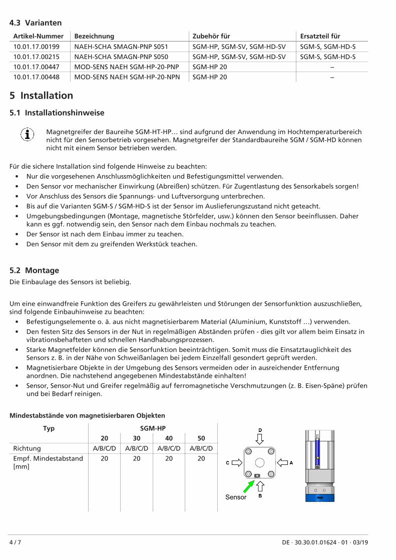
• Magnetisierbare Objekte in der Umgebung des Sensors vermeiden oder in ausreichender Entfernunganordnen. Die nachstehend angegebenen Mindestabstände einhalten!
• Sensor, Sensor-Nut und Greifer regelmäßig auf ferromagnetische Verschmutzungen (z. B. Eisen-Späne) prüfenund bei Bedarf reinigen.
Mindestabstände von magnetisierbaren Objekten
Typ SGM-HP
Sensor
20 30 40 50
Richtung A/B/C/D A/B/C/D A/B/C/D A/B/C/D
Empf. Mindestabstand[mm]
20 20 20 20
4 / 7 DE · 30.30.01.01624 · 01 · 03/19
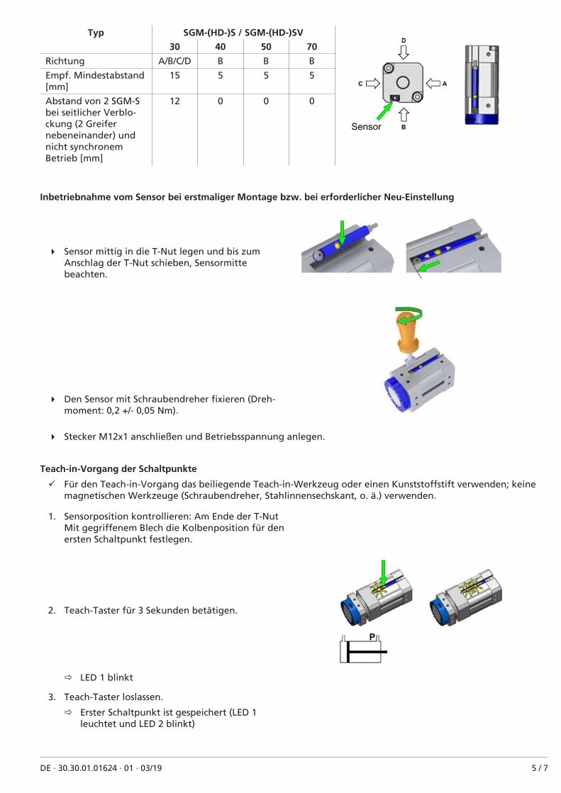
Typ SGM-(HD-)S / SGM-(HD-)SV
Sensor
30 40 50 70
Richtung A/B/C/D B B B
Empf. Mindestabstand[mm]
15 5 5 5
Abstand von 2 SGM-Sbei seitlicher Verblo-ckung (2 Greifernebeneinander) undnicht synchronemBetrieb [mm]
12 0 0 0
Inbetriebnahme vom Sensor bei erstmaliger Montage bzw. bei erforderlicher Neu-Einstellung
4 Sensor mittig in die T-Nut legen und bis zumAnschlag der T-Nut schieben, Sensormittebeachten.
4 Den Sensor mit Schraubendreher fixieren (Dreh-moment: 0,2 +/- 0,05 Nm).
4 Stecker M12x1 anschließen und Betriebsspannung anlegen.
Teach-in-Vorgang der Schaltpunkte
ü Für den Teach-in-Vorgang das beiliegende Teach-in-Werkzeug oder einen Kunststoffstift verwenden; keinemagnetischen Werkzeuge (Schraubendreher, Stahlinnensechskant, o. ä.) verwenden.
1. Sensorposition kontrollieren: Am Ende der T-NutMit gegriffenem Blech die Kolbenposition für denersten Schaltpunkt festlegen.
2. Teach-Taster für 3 Sekunden betätigen.
ð LED 1 blinkt
3. Teach-Taster loslassen.
ð Erster Schaltpunkt ist gespeichert (LED 1leuchtet und LED 2 blinkt)
DE · 30.30.01.01624 · 01 · 03/19 5 / 7

4. Die Kolbenposition für den zweiten Schaltpunktfestlegen.
ð LED 1 erlischt und LED 2 blinkt.
5. Den Teach-Taster kurz betätigen.
ð Der zweite Schaltpunkt ist gespeichert (LED 2leuchtet).
Kontrolle 1. Schaltpunkt
1. Den Kolben in Stellung für den ersten Schaltpunkt bewegen.
ð LED 1 leuchtet
2. LED 1 leuchtet nicht.
ð Die Einsatzbedingungen prüfen und neu justieren.
Kontrolle 2. Schaltpunkt
1. Den Kolben in Stellung für den zweiten Schaltpunkt bewegen.
ð LED 1 erlischt und LED 2 leuchtet.
2. Erlischt die LED 1 nicht bzw. leuchtet die LED 2 nicht.
ð Die Einsatzbedingungen prüfen und neu justieren.
6 WartungDer Sensor ist wartungsfrei.
Wir empfehlen:
1. Die Flächen der LED's regelmäßig reinigen.
2. Die Verschraubung und die Steckverbindung regelmäßig prüfen.
7 Ersatz- und VerschleißteileArtikel-Nr. Typ Bezeichnung Art
10.01.17.00509 ZUB SGM-S NAEH-SCHA Schraube Schraube Ersatzteil
10.01.17.00510 ZUB SGM-S NAEH-SCHA PIN Kunststoff-Pin Ersatzteil
4 Beim Festziehen der Befestigungsschraube das maximale Anzugsmoment von 0,2 +/- 0,05 Nm beachten.
8 Sensor entsorgen1. Das Produkt nach einem Tausch oder der Außerbetriebnahme fachgerecht entsorgen.
2. Die länderspezifischen Richtlinien und gesetzlichen Verpflichtungen zur Abfallvermeidung und Entsorgungbeachten.
9 IO-Link Konfiguration nur für PNP-Variante
Sehen Sie dazu auch
2 Schmalz Näherungsschalter Data Dictionary 21.10.01.00118_00.pdf [} 7]
6 / 7 DE · 30.30.01.01624 · 01 · 03/19

IO�Link Data Dictionary magnetic switch21.10.01.00118/00 05.04.2018
J. Schmalz GmbH
Johannes-Schmalz-Str.1
D 72293 Glatten
Tel.: +49(0)7443/2403-0
Fax: +49(0)7443/2403-259
1 Boolean ro Logic state of switch point 2
0 Boolean ro Logic state of switch point 1
Subindex
dec hex dec
�
16 0x0010 0 64 bytes ro J. SCHMALZ GMBH Manufacturer designation
18 0x0012 0 64 bytes ro SMAGN S051 General product name
21 0x0015 0 16 bytes ro Serial number
22 0x0016 0 64 bytes ro 1.10 Hardware revison
23 0x0017 0 64 bytes ro 2.42 Firmware revision
24 0x0018 0 16 bytes rw User string to store location or tooling information
�
�
2 0x0002 0 1 byte 160, 161, 163, 164 wo
0xA0 (dec 160): teaching of switch point 1
0xA1 (dec 161): teaching of switch point 2
0xA3 (dec 163): global key lock
0xA4 (dec 164): global key unlock
�144 0x0090 0 8 bytes ro teached parameter of switch point 1
145 0x0091 0 8 bytes ro teached parameter of switch point 2
146 0x0092 1 1 byte 1 : 5 rw 1
146 0x0092 2 1 byte 1 : 5 rw 1
147 0x0093 0 1 byte ro 1
148 0x0094 0 1 byte ro 0
0...127 teach button not locked
128 teach button locked
129...255 teach button not locked
�
�40 0x0028 0 1 byte ro Copy of currently active process data input
IO�Link Implementation
Process Data
Remark
Switching Point 2
Name
234 (0x00EA)
1179758 (0x12006E)
Yes
1.0
Device ID
SIO�Mode
38.4 kBit/sec (COM2)
2.3 ms
1 bytes
Switching Point 1
Process Data Input
IO�Link Revision
Vendor ID
Process Data Input
Process Data Output
IO�Link Bitrate
Minimum Cycle Time
Teach Button Status
Identification
Firmware Revision
Application Specific Tag
Process Settings
Device Settings
Hardware Revision
Tolerance Level SP1
Vendor Name
Product Name
System Command
Monitoring
Process Data In Copy
Observation
Tolerance Level Default
Value Range
Bits
Display
Appearance
Tolerance Level SP2
ISDU Index
� Device Management
PD In Byte 0
None
Special Values
Parameter
Teach parameter SP1
Teach parameter SP2
Data Type Access
ISDU Parameters
RemarkDefault Value
Serial Number
Parameter
Size Access
J. Schmalz GmbH 1 of 1 magnetic switch Data Dictionary

Proximity switch for magnetic gripper
Operating Instructions
Note
The operating instructions were originally written in German. Store in a safe place for future reference. Subjectto technical changes without notice. No responsibility is taken for printing or other types of errors.
Published by
© J. Schmalz GmbH, 03/19
This document is protected by copyright. J. Schmalz GmbH retains the rights established thereby. Reproduction ofthe contents, in full or in part, is only permitted within the limits of the legal provisions of copyright law. Any mod-ifications to or abridgments of the document are prohibited without explicit written agreement fromJ. Schmalz GmbH.
J. Schmalz GmbH · Johannes-Schmalz-Str. 1 · 72293 Glatten, Germany · T: +49 7443 2403-0
EN-US · 30.30.01.01624 · 01 · 03/19

1 Important information
1.1 Note on Using this DocumentJ. Schmalz GmbH is generally referred to as Schmalz in this operating instructions.
These operating instructions contain important notes and information about the different operating phases of theproduct:
• Transport, storage, start of operations and decommissioning
• Safe operation, required maintenance, rectification of any faults
The operating instructions describe the product at the time of delivery by Schmalz.
1.2 Symbol
This sign indicates useful and important information.
ü This symbol represents a prerequisite that must be met before an action is performed.
4 This sign represents an action to be performed.
ð This sign represents the result of an action.
Actions that consist of more than one step are numbered:
1. First action to be performed.
2. Second action to be performed.
2 Safety
2.1 Safety instructionsThe product is used in combination with an automated handling system (gantry/robot). Therefore, in addition tothe safety instructions described here, the safety regulations of the corresponding system apply.
2.2 The technical documentation is part of the product
1. For problem-free and safe operation, follow the instructions in the documents.
2. Keep the technical documentation in close proximity to the product. The documentation must be accessibleto personnel at all times.
3. Pass on the technical documentation to subsequent users.
ð Failure to follow the instructions in this operating instructions may lead to life-threatening injuries!
ð Schmalz is not liable for damage or malfunctions that result from failure to heed these instructions.
If you still have questions after reading the technical documentation, contactSchmalz-service at:
www.schmalz.com/services
2.3 Intended useThe proximity switch is used to detect two end positions on magnetic cylinders. Only the PNP variant can be readout and set via IO link.
This device has been designed, developed and constructed solely for industrial and commercial use. Private use isexcluded.
Intended use includes the observance of the technical data and the installation and operating instructions in thismanual.
2.4 Personnel qualificationUnqualified personnel cannot recognize dangers and are therefore exposed to higher risks!
1. Electrical work and installations may only be carried out by qualified electrical specialists.
2. Assembly and adjustment work may only be carried out by qualified personnel.
2 / 7 EN-US · 30.30.01.01624 · 01 · 03/19

3 Technical dataPower supply UV DC 12 to 30 V
Power consumption (inactive) I ≤ 15 mA
Continuous current Ia ≤ 100 mA
Switching output PNP/NPN
Output function Normally open
Connection cable M12x1 L=0.3 m
EMV EN 60 947-5-2
Degree of protection IP 67
Ambient temperature -20 to +75
4 Product description
4.1 Dimensions and designations
1 Fastening screw
5
6
2 LED 2 – setting down
3 Teach button
4 LED 1 – gripping
5 Electrical connection M12x1
6 Center of sensor
4.2 Electrical connection
Variant PNP NPN
Circuit diagram
Us
Q1
Q2GNDs
Us
Q1
Q2GNDs
ConnectorM12-1
Pin Lead color Symbol Function
1 Brown US Supply voltage
2 White Q1 Signal output 1 (LED 2)
3 Blue GNDS Ground
4 Black Q2 Signal output 2 (LED 1)
EN-US · 30.30.01.01624 · 01 · 03/19 3 / 7

4.3 Variants
Part number Designation Accessories for Spare parts for
10.01.17.00199 NAEH-SCHA SMAGN-PNP S051 SGM-HP, SGM-SV, SGM-HD-SV SGM-S, SGM-HD-S
10.01.17.00215 NAEH-SCHA SMAGN-PNP S050 SGM-HP, SGM-SV, SGM-HD-SV SGM-S, SGM-HD-S
10.01.17.00447 MOD-SENS NAEH SGM-HP-20-PNP SGM-HP 20 —
10.01.17.00448 MOD-SENS NAEH SGM-HP-20-NPN SGM-HP 20 —
5 Installation
5.1 Installation instructions
Magnetic grippers of the series SGM-HT-HP ... are not intended for sensor operation due to their appli-cation in the high temperature range. Magnetic grippers of the standard series SGM / SGM-HD cannotbe operated with a sensor.
For safe installation, the following instructions must be observed:
• Use only the connections and attachment materials that have been provided.
• Protect the sensor from mechanical damage (breaking off). Provide strain relief for the sensor cable.
• Disconnect the voltage and air supply before connecting the sensor.
• Except for the variants SGM-S / SGM-HD-S, the sensor is not delivered preconfigured.
• Environmental conditions (assembly, magnetic interference fields, etc.) can affect the sensor. Therefore, itmay be necessary to teach the sensor again after installation.
• The sensor must always be taught after installation.
• Teach the sensor with the workpiece to be gripped.
5.2 MountingThe sensor may be installed in any position.
To ensure that the gripper functions properly and to prevent faults in the sensor function, observe the followinginstallation instructions:
• Use mounting elements or similar made of non-magnetizable material (aluminum, plastic, etc.)
• Check on a regular basis that the sensor is securely installed in the slot – in particular when it is used in fasthandling processes or ones that are exposed to vibration.
• Strong magnetic fields can impair the functionality of the sensor. As a result, the suitability of the sensor foruse, for example in close proximity to welding plants, must be checked separately in each individual case.
• Keep magnetizable objects away from the sensor or place them at a sufficient distance. Observe the mini-mum distances specified below.
• The sensor, sensor slot, and gripper(s) must be regularly inspected and any ferromagnetic pollutants (such asiron shavings) removed.
Minimum distances of magnetizable objects
Type SGM-HP
Sensor
20 30 40 50
Direction A/B/C/D A/B/C/D A/B/C/D A/B/C/D
Rec. minimum dis-tance [mm]
20 20 20 20
4 / 7 EN-US · 30.30.01.01624 · 01 · 03/19

Type SGM-(HD-)S / SGM-(HD-)SV
Sensor
30 40 50 70
Direction A/B/C/D B B B
Rec. minimum dis-tance [mm]
15 5 5 5
Distance of 2 SGM-Sfor block mounting atthe side (2 grippersnext to each other)and asynchronous op-eration [mm]
12 0 0 0
Commissioning of the sensor for first time installation or resetting, where necessary
4 Place the sensor in the middle of the T-slot andpush it to the stop of the T-slot. Observe the centerof the sensor.
4 Fix the sensor with a screwdriver (torque: 0.2 +/-0.05 Nm).
4 Connect plug M12x1 and apply operating voltage.
Teaching in the switching points
ü Use the supplied teach-in tool or a plastic pin for the teach-in process; do not use magnetic tools (screwdriver,steel hexagonal socket wrench, etc.).
1. Check sensor position: at the end of the T-slotWith the sheet clamped, set the piston position forthe first switching point.
2. Press and hold the Teach button for 3 seconds.
ð LED 1 flashes
3. Release the Teach button.
ð First switching point is stored (LED 1 lights upand LED 2 flashes)
EN-US · 30.30.01.01624 · 01 · 03/19 5 / 7

4. Set the piston position for the second switchingpoint.
ð LED 1 is extinguished and LED 2 flashes.
5. Press the Teach button briefly.
ð The second switching point is stored (LED 2lights up).
Inspection of first switching point
1. Move the piston to the position for the first switching point.
ð LED 1 illuminated
2. LED 1 not illuminated.
ð Check the operating conditions and adjust accordingly.
Inspection of second switching point
1. Move the piston to the position for the second switching point.
ð LED 1 is extinguished and LED 2 lights up.
2. If LED 1 does not turn off or LED 2 does not light up,
ð check the operating conditions and adjust accordingly.
6 MaintenanceThe sensor does not require maintenance.
We recommend:
1. Cleaning the surfaces of the LEDs regularly.
2. Checking the screw union and the plug connection regularly.
7 Spare and wearing partsPart no. Type Designation Type
10.01.17.00509 ZUB SGM-S NAEH-SCHA Screw Screw Spare part
10.01.17.00510 ZUB SGM-S NAEH-SCHA PIN Plastic pin Spare part
4 When tightening the fastening screws, observe the maximum tightening torque of 0.2 +/- 0.05 Nm.
8 Disposing of the sensor1. Dispose of the product properly after replacement or decommissioning.
2. Observe the country-specific guidelines and legal obligations for waste prevention and disposal.
9 IO link configuration for PNP variant only
See also
2 Schmalz Näherungsschalter Data Dictionary 21.10.01.00118_00.pdf [} 7]
6 / 7 EN-US · 30.30.01.01624 · 01 · 03/19

IO�Link Data Dictionary magnetic switch21.10.01.00118/00 05.04.2018
J. Schmalz GmbH
Johannes-Schmalz-Str.1
D 72293 Glatten
Tel.: +49(0)7443/2403-0
Fax: +49(0)7443/2403-259
1 Boolean ro Logic state of switch point 2
0 Boolean ro Logic state of switch point 1
Subindex
dec hex dec
�
16 0x0010 0 64 bytes ro J. SCHMALZ GMBH Manufacturer designation
18 0x0012 0 64 bytes ro SMAGN S051 General product name
21 0x0015 0 16 bytes ro Serial number
22 0x0016 0 64 bytes ro 1.10 Hardware revison
23 0x0017 0 64 bytes ro 2.42 Firmware revision
24 0x0018 0 16 bytes rw User string to store location or tooling information
�
�
2 0x0002 0 1 byte 160, 161, 163, 164 wo
0xA0 (dec 160): teaching of switch point 1
0xA1 (dec 161): teaching of switch point 2
0xA3 (dec 163): global key lock
0xA4 (dec 164): global key unlock
�144 0x0090 0 8 bytes ro teached parameter of switch point 1
145 0x0091 0 8 bytes ro teached parameter of switch point 2
146 0x0092 1 1 byte 1 : 5 rw 1
146 0x0092 2 1 byte 1 : 5 rw 1
147 0x0093 0 1 byte ro 1
148 0x0094 0 1 byte ro 0
0...127 teach button not locked
128 teach button locked
129...255 teach button not locked
�
�40 0x0028 0 1 byte ro Copy of currently active process data input
IO�Link Implementation
Process Data
Remark
Switching Point 2
Name
234 (0x00EA)
1179758 (0x12006E)
Yes
1.0
Device ID
SIO�Mode
38.4 kBit/sec (COM2)
2.3 ms
1 bytes
Switching Point 1
Process Data Input
IO�Link Revision
Vendor ID
Process Data Input
Process Data Output
IO�Link Bitrate
Minimum Cycle Time
Teach Button Status
Identification
Firmware Revision
Application Specific Tag
Process Settings
Device Settings
Hardware Revision
Tolerance Level SP1
Vendor Name
Product Name
System Command
Monitoring
Process Data In Copy
Observation
Tolerance Level Default
Value Range
Bits
Display
Appearance
Tolerance Level SP2
ISDU Index
� Device Management
PD In Byte 0
None
Special Values
Parameter
Teach parameter SP1
Teach parameter SP2
Data Type Access
ISDU Parameters
RemarkDefault Value
Serial Number
Parameter
Size Access
J. Schmalz GmbH 1 of 1 magnetic switch Data Dictionary

Interruptor de proximidad para garra magnética
Instrucciones de funcionamiento
Nota
El Instrucciones de funcionamiento ha sido redactado en alemán. Conservar para uso futuro. Reservado el dere-cho a realizar modificaciones por causas técnicas. No nos responsabilizamos por fallos en la impresión u otroserrores.
Editor
© J. Schmalz GmbH, 03/19
Esta obra está protegida por los derechos de autor. Los derechos de esta son propiedad de la empresa J. SchmalzGmbH. La reproducción total o parcial de esta obra está solo permitida en el marco de las disposiciones legales dela Ley de protección de los derechos de autor. Está prohibido cambiar o acortar la obra sin la autorización expresapor escrito de la empresa J. Schmalz GmbH.
J. Schmalz GmbH · Johannes-Schmalz-Str. 1 · D-72293 Glatten · T: +49 7443 2403-0
ES · 30.30.01.01624 · 01 · 03/19

1 Información importante
1.1 Nota para el uso de este documentoJ. Schmalz GmbH se denominará en general en este Instrucciones de funcionamiento Schmalz.
Este Instrucciones de funcionamiento contiene importantes notas e informaciones relativas a las distintas fases defuncionamiento del producto:
• Transporte, almacenamiento, puesta en marcha y puesta fuera de servicio
• Funcionamiento seguro, trabajos de mantenimiento necesarios, solución de posibles fallos
En el Instrucciones de funcionamiento se describe el producto en el momento de ser entregado por Schmalz.
1.2 Símbolos
Este signo hace referencia a información útil e importante.
ü Este signo hace referencia a un requisito que debe estar cumplido antes de efectuar una intervención.
4 Este signo hace referencia a una intervención a efectuar.
ð Este signo hace referencia al resultado de una intervención.
Las intervenciones que constan de más de un paso están numeradas:
1. Primera intervención a efectuar.
2. Segunda intervención a efectuar.
2 Seguridad
2.1 Nota de seguridadEl producto se utiliza en combinación con un sistema de manipulación automatizado (pórtico/robot). Por este moti-vo, adicionalmente a las notas de seguridad que se describen aquí, tienen validez las prescripciones de seguridaddel respectivo sistema.
2.2 La Documentación Técnica forma parte del producto
1. Siga las indicaciones en los documentos para asegurar un funcionamiento seguro y sin problemas.
2. Guarde la Documentación Técnica en las proximidades del producto. Debe estar accesible en todo momentopara el personal.
3. Entregue la Documentación Técnica a usuarios posteriores.
ð ¡El incumplimiento de las indicaciones de este Instrucciones de funcionamiento puede causar lesiones morta-les!
ð Schmalz no asume ninguna responsabilidad por los daños y fallos de funcionamiento que resulten de la inob-servancia de las indicaciones.
Si tras leer la documentación técnica aún tiene alguna pregunta, póngase en contacto con el servicio técnico deSchmalz:
www.schmalz.com/services
2.3 Uso adecuadoEl interruptor de proximidad sirve para el reconocimiento de dos posiciones finales en cilindros magnéticos. Solo sepuede leer y ajustar la variante PNP a través de IO-Link.
Este dispositivo ha sido desarrollado, construido y fabricado exclusivamente para el uso industrial. El uso privadoqueda excluido.
La observación de los Datos Técnicos y de las Indicaciones para Montaje y Funcionamiento en el presente manualforman parte del uso adecuado.
2.4 Cualificación del personalEl personal no cualificado no puede reconocer los riesgos y, por tanto, está expuesto a peligros mayores.
1. Los trabajos eléctricos y las instalaciones han de ser realizados exclusivamente por electricistas especializados.
2 / 8 ES · 30.30.01.01624 · 01 · 03/19
2. Los trabajos de montaje y de ajuste han de ser efectuados exclusivamente por especialistas correspondientes.
3 Datos técnicosTensión de alimentación UV DC 12…30 V
Consumo de corriente (no activado) I ≤ 15 mA
Corriente constante Ia ≤ 100 mA
Salida de conmutación PNP/NPN
Función de salida Contacto NO
Cable de conexión M12x1 L=0,3 m
CEM EN 60 947-5-2
Tipo de protección IP 67
Temperatura ambiente -20….+75
4 Descripción del producto
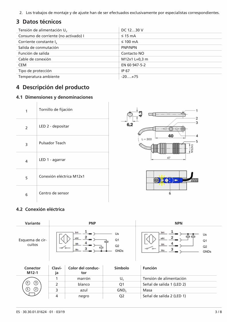
4.1 Dimensiones y denominaciones
1 Tornillo de fijación
5
6
2 LED 2 - depositar
3 Pulsador Teach
4 LED 1 - agarrar
5 Conexión eléctrica M12x1
6 Centro de sensor
4.2 Conexión eléctrica
Variante PNP NPN
Esquema de cir-cuitos
Us
Q1
Q2GNDs
Us
Q1
Q2GNDs
ConectorM12-1
Clavi-ja
Color del conduc-tor
Símbolo Función
1 marrón US Tensión de alimentación
2 blanco Q1 Señal de salida 1 (LED 2)
3 azul GNDS Masa
4 negro Q2 Señal de salida 2 (LED 1)
ES · 30.30.01.01624 · 01 · 03/19 3 / 8
4.3 Variantes
Número de artí-culo
Designación Accesorios para Pieza de repuestopara
10.01.17.00199 NAEH-SCHA SMAGN-PNP S051 SGM-HP, SGM-SV, SGM-HD-SV SGM-S, SGM-HD-S
10.01.17.00215 NAEH-SCHA SMAGN-PNP S050 SGM-HP, SGM-SV, SGM-HD-SV SGM-S, SGM-HD-S
10.01.17.00447 MOD-SENS NAEH SGM-HP-20-PNP SGM-HP 20 −
10.01.17.00448 MOD-SENS NAEH SGM-HP-20-NPN SGM-HP 20 −
5 Instalación
5.1 Indicaciones para la instalación
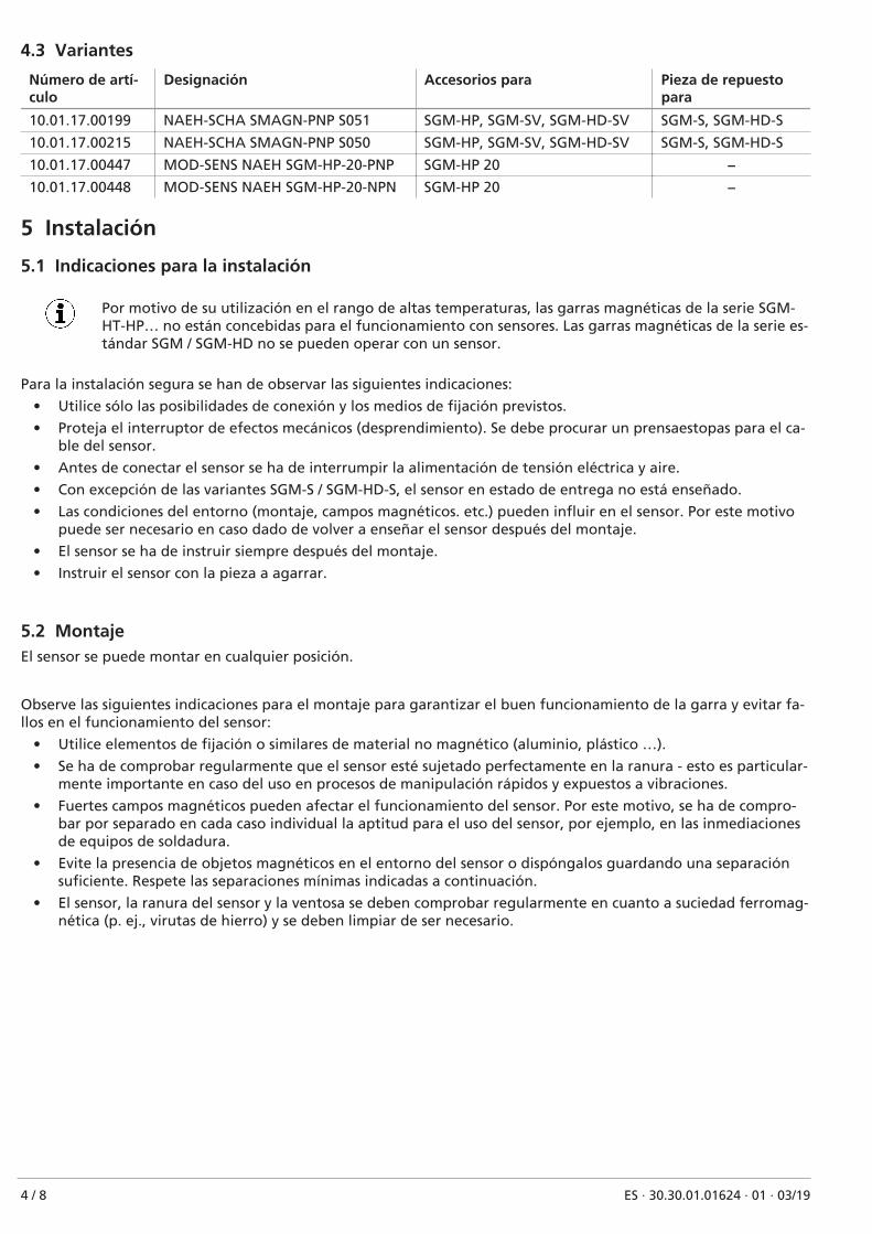
Por motivo de su utilización en el rango de altas temperaturas, las garras magnéticas de la serie SGM-HT-HP… no están concebidas para el funcionamiento con sensores. Las garras magnéticas de la serie es-tándar SGM / SGM-HD no se pueden operar con un sensor.
Para la instalación segura se han de observar las siguientes indicaciones:
• Utilice sólo las posibilidades de conexión y los medios de fijación previstos.
• Proteja el interruptor de efectos mecánicos (desprendimiento). Se debe procurar un prensaestopas para el ca-ble del sensor.
• Antes de conectar el sensor se ha de interrumpir la alimentación de tensión eléctrica y aire.
• Con excepción de las variantes SGM-S / SGM-HD-S, el sensor en estado de entrega no está enseñado.
• Las condiciones del entorno (montaje, campos magnéticos. etc.) pueden influir en el sensor. Por este motivopuede ser necesario en caso dado de volver a enseñar el sensor después del montaje.
• El sensor se ha de instruir siempre después del montaje.
• Instruir el sensor con la pieza a agarrar.
5.2 MontajeEl sensor se puede montar en cualquier posición.
Observe las siguientes indicaciones para el montaje para garantizar el buen funcionamiento de la garra y evitar fa-llos en el funcionamiento del sensor:
• Utilice elementos de fijación o similares de material no magnético (aluminio, plástico …).
• Se ha de comprobar regularmente que el sensor esté sujetado perfectamente en la ranura - esto es particular-mente importante en caso del uso en procesos de manipulación rápidos y expuestos a vibraciones.
• Fuertes campos magnéticos pueden afectar el funcionamiento del sensor. Por este motivo, se ha de compro-bar por separado en cada caso individual la aptitud para el uso del sensor, por ejemplo, en las inmediacionesde equipos de soldadura.
• Evite la presencia de objetos magnéticos en el entorno del sensor o dispóngalos guardando una separaciónsuficiente. Respete las separaciones mínimas indicadas a continuación.
• El sensor, la ranura del sensor y la ventosa se deben comprobar regularmente en cuanto a suciedad ferromag-nética (p. ej., virutas de hierro) y se deben limpiar de ser necesario.
4 / 8 ES · 30.30.01.01624 · 01 · 03/19

Separaciones mínimas de objetos magnéticos
Tipo SGM-HP
Sensor
20 30 40 50
Sentido A/B/C/D A/B/C/D A/B/C/D A/B/C/D
Separación mínima re-comendada [mm]
20 20 20 20
Tipo SGM-(HD-)S / SGM-(HD-)SV
Sensor
30 40 50 70
Sentido A/B/C/D B B B
Separación mínima re-comendada [mm]
15 5 5 5
Separación de 2 SGM-Sen caso de bloqueo la-teral (2 garras yuxta-puestas) y funciona-miento no síncrono[mm]
12 0 0 0
Puesta en marcha del sensor durante el primer montaje o cuando se necesite un reajuste
4 Coloque el sensor en el centro de la ranura en T ymuévalo hasta el tope de la ranura en T, teniendoen cuenta el centro de sensor.
4 Fije el sensor con el destornillador (par: 0,2 +/-0,05 Nm).
4 Conecte el conector M12x1 y aplique la tensión de servicio.
ES · 30.30.01.01624 · 01 · 03/19 5 / 8

Procesos de Teach-in de los puntos de conmutación
ü Utilice para el proceso de Teach-in la herramienta de Teach-in adjunta o una clavija de plástico; no empleeherramientas magnéticas (destornillador, llave Allen de acero o similares).
1. Controlar la posición del sensor: En el extremo dela ranura en TCon ayuda de chapa corrugada defina la posicióndel pistón para el primer punto de conmutación.
2. Presione durante 3 segundos el pulsador Teach.
ð LED 1 parpadea
3. Suelte el pulsador Teach.
ð El primer punto de conmutación está guardado(LED 1 luce y LED 2 parpadea).
4. Defina la posición del pistón para el segundo pun-to de conmutación.
ð LED 1 se apaga y LED 2 parpadea.
5. Presione brevemente el pulsador Teach.
ð El segundo punto de conmutación está guarda-do (LED 2 luce).
Control 1° punto de conmutación
1. Mueva el pistón a la posición para el primer punto de conmutación.
ð LED 1 luce.
2. LED 1 no luce.
ð Compruebe las condiciones de uso y reajuste.
Control 2° punto de conmutación
1. Mueva el pistón a la posición para el segundo punto de conmutación.
ð LED 1 se apaga y LED 2 luce.
2. Si no se apaga el LED 1 o si no luce el LED 2.
ð Compruebe las condiciones de uso y reajuste.
6 / 8 ES · 30.30.01.01624 · 01 · 03/19

6 MantenimientoEl interruptor no necesita mantenimiento.
Recomendamos:
1. Limpiar regularmente las superficies de los LEDs.
2. Comprobar regularmente la atornilladura y el racor.
7 Piezas de repuesto y piezas sometidas al desgasteN.º de artículo Tipo Designación Clase
10.01.17.00509 ZUB SGM-S NAEH-SCHA Schraube Tornillo Pieza de repuesto
10.01.17.00510 ZUB SGM-S NAEH-SCHA PIN Clavija de plástico Pieza de repuesto
4 Tenga en cuenta el par de apriete máximo de 0,2 +/- 0,05 Nm al apretar el tornillo de fijación.
8 Eliminar el sensor1. Después de una sustitución o la puesta fuera de servicio se ha de eliminar correctamente el producto.
2. Observe las directivas del país específico y las obligaciones legales para prevención y eliminación de residuos.
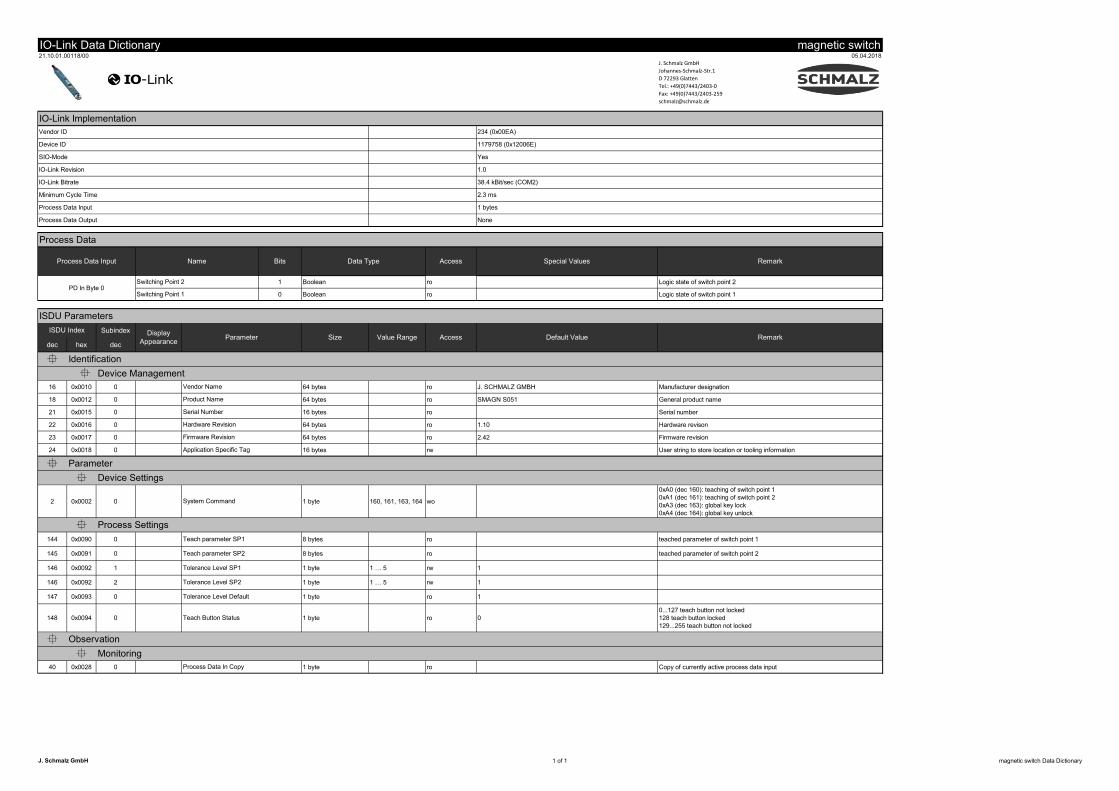
9 Configuración de IO-Link solo para variante PNP
Véase también al respecto
2 Schmalz Näherungsschalter Data Dictionary 21.10.01.00118_00.pdf [} 8]
ES · 30.30.01.01624 · 01 · 03/19 7 / 8
IO�Link Data Dictionary magnetic switch21.10.01.00118/00 05.04.2018
J. Schmalz GmbH
Johannes-Schmalz-Str.1
D 72293 Glatten
Tel.: +49(0)7443/2403-0
Fax: +49(0)7443/2403-259
1 Boolean ro Logic state of switch point 2
0 Boolean ro Logic state of switch point 1
Subindex
dec hex dec
�
16 0x0010 0 64 bytes ro J. SCHMALZ GMBH Manufacturer designation
18 0x0012 0 64 bytes ro SMAGN S051 General product name
21 0x0015 0 16 bytes ro Serial number
22 0x0016 0 64 bytes ro 1.10 Hardware revison
23 0x0017 0 64 bytes ro 2.42 Firmware revision
24 0x0018 0 16 bytes rw User string to store location or tooling information
�
�
2 0x0002 0 1 byte 160, 161, 163, 164 wo
0xA0 (dec 160): teaching of switch point 1
0xA1 (dec 161): teaching of switch point 2
0xA3 (dec 163): global key lock
0xA4 (dec 164): global key unlock
�144 0x0090 0 8 bytes ro teached parameter of switch point 1
145 0x0091 0 8 bytes ro teached parameter of switch point 2
146 0x0092 1 1 byte 1 : 5 rw 1
146 0x0092 2 1 byte 1 : 5 rw 1
147 0x0093 0 1 byte ro 1
148 0x0094 0 1 byte ro 0
0...127 teach button not locked
128 teach button locked
129...255 teach button not locked
�
�40 0x0028 0 1 byte ro Copy of currently active process data input
IO�Link Implementation
Process Data
Remark
Switching Point 2
Name
234 (0x00EA)
1179758 (0x12006E)
Yes
1.0
Device ID
SIO�Mode
38.4 kBit/sec (COM2)
2.3 ms
1 bytes
Switching Point 1
Process Data Input
IO�Link Revision
Vendor ID
Process Data Input
Process Data Output
IO�Link Bitrate
Minimum Cycle Time
Teach Button Status
Identification
Firmware Revision
Application Specific Tag
Process Settings
Device Settings
Hardware Revision
Tolerance Level SP1
Vendor Name
Product Name
System Command
Monitoring
Process Data In Copy
Observation
Tolerance Level Default
Value Range
Bits
Display
Appearance
Tolerance Level SP2
ISDU Index
� Device Management
PD In Byte 0
None
Special Values
Parameter
Teach parameter SP1
Teach parameter SP2
Data Type Access
ISDU Parameters
RemarkDefault Value
Serial Number
Parameter
Size Access
J. Schmalz GmbH 1 of 1 magnetic switch Data Dictionary

Capteur de proximité pour préhenseur magnétique
Notice d’utilisation
Remarque
La Notice d'utilisation a été rédigée en allemand, puis traduite en français. À conserver pour toute utilisation ul-térieure. Sous réserve de modifications techniques, d’erreurs ou de fautes d’impression.
Éditeur
© J. Schmalz GmbH, 03/19
Cet ouvrage est protégé par la propriété intellectuelle. Tous les droits relatifs appartiennent à la société J. SchmalzGmbH. Toute reproduction de l’ouvrage, même partielle, n’est autorisée que dans les limites légales prévues par ledroit de la propriété intellectuelle. Toute modification ou abréviation de l’ouvrage doit faire l’objet d’un accordécrit préalable de la société J. Schmalz GmbH.
J. Schmalz GmbH · Johannes-Schmalz-Str. 1 · D-72293 Glatten · T : +49 7443 2403-0
FR · 30.30.01.01624 · 01 · 03/19

1 Informations importantes
1.1 Remarque concernant l’utilisation du présent documentLa société J. Schmalz GmbH est généralement mentionnée sous le nom de Schmalz dans ce Notice d'utilisation.
Ce Notice d'utilisation contient des consignes et des informations importantes au sujet des différentes phases d’ex-ploitation du produit :
• le transport, le stockage, la mise en service et la mise hors service
• le fonctionnement fiable, les travaux de maintenance requis, la réparation d’éventuels dysfonctionnements
Le Notice d'utilisation décrit le produit au moment de la livraison par Schmalz.
1.2 Symboles
Ce symbole indique des informations utiles et importantes.
ü Ce symbole indique une condition requise devant être remplie avant toute manipulation.
4 Ce symbole indique une manipulation à effectuer.
ð Ce symbole indique le résultat d’une manipulation.
Les manipulations qui comprennent plusieurs étapes sont numérotées :
1. Première manipulation à effectuer.
2. Seconde manipulation à effectuer.
2 Sécurité
2.1 Consigne de sécuritéLe produit est utilisé en association avec un système de manipulation automatique (portique / robot). Pour cetteraison, en plus des consignes de sécurité énoncées ici, les règlements de sécurité du système concerné s’appliquentégalement !
2.2 La documentation technique fait partie du produit
1. Veuillez respecter les consignes mentionnées dans les documents afin de garantir la sécurité de l’installationet afin d’éviter des dysfonctionnements.
2. Veuillez conserver la documentation technique à proximité du produit. Elle doit toujours être à la dispositiondu personnel.
3. Veuillez transmettre la documentation technique aux utilisateurs ultérieurs.
ð Tout non-respect des consignes indiquées dans le document Notice d'utilisation peut entraîner des blessuresmettant la vie en danger !
ð Schmalz n'assume aucune responsabilité en cas de dommages et de pannes résultant du non respect des re-marques de la documentation.
Si, après avoir lu la documentation technique, vous avez encore des questions, veuillez vous adresser au serviceSch-malz à l’adresse suivante :
www.schmalz.com/services
2.3 Utilisation conformeLe détecteur de proximité sert à identifier deux fins de course sur des cylindres magnétiques. Seule la variante PNPpeut être lue et réglée via IO-Link.
Ce dispositif a été développé, conçu et construit exclusivement pour une utilisation industrielle et commerciale.Tout usage privé est exclu.
Respecter les données techniques ainsi que les indications de montage et de service mentionnées dans la présentenotice fait partie de l’utilisation conforme.
2.4 Qualification du personnelDu personnel non qualifié n’est pas en mesure de reconnaître des risques et est de fait exposé à des dangers ac-crus !
2 / 8 FR · 30.30.01.01624 · 01 · 03/19

1. Seuls des électriciens qualifiés sont habilités à effectuer des travaux sur l’équipement électrique et les installa-tions.
2. Seuls des spécialistes dans le domaine sont autorisés à procéder à des travaux de montage et de réglage.
3 Données techniquesTension d’alimentation UV CC 12…30 V
Consommation de courant (inactive) I ≤ 15 mA
Courant continu Ia ≤ 100 mA
Sortie de commutation PNP/NPN
Fonction de sortie Contact à fermeture
Câble de raccordement M12x1 L=0,3 m
Électrovanne EMV EN 60 947-5-2
Type de protection IP 67
Température ambiante -20….+75
4 Description du produit
4.1 Dimensions et désignations
1 Vis de fixation
5
6
2 LED 2 – dépose
3 Touche Teach (programmation)
4 LED 1 – préhension
5 Connexion électrique M12x1
6 Centre du capteur
4.2 Raccordement électrique
Variante PNP NPN
Schéma de câ-blage
Us
Q1
Q2GNDs
Us
Q1
Q2GNDs
FR · 30.30.01.01624 · 01 · 03/19 3 / 8

ConnecteurM12-1
Broche
Couleur des brins Symbole Fonction
1 Marron US Tension d’alimentation
2 Blanc Q1 Sortie de signal 1 (LED 2)
3 Bleu GNDS Masse
4 Noir Q2 Sortie de signal 2 (LED 1)
4.3 Variantes
Réf. article Désignation Accessoire pour Pièce de rechangepour
10.01.17.00199 NAEH-SCHA SMAGN-PNP S051 SGM-HP, SGM-SV, SGM-HD-SV SGM-S, SGM-HD-S
10.01.17.00215 NAEH-SCHA SMAGN-PNP S050 SGM-HP, SGM-SV, SGM-HD-SV SGM-S, SGM-HD-S
10.01.17.00447 MOD-SENS NAEH SGM-HP-20-PNP SGM-HP 20 −
10.01.17.00448 MOD-SENS NAEH SGM-HP-20-NPN SGM-HP 20 −
5 Installation
5.1 Consignes d'installation
Les préhenseurs magnétiques de la série SGM-HT-HP... ne sont pas prévus pour un fonctionnement ducapteur en raison de l’utilisation dans des zones à haute température. Les préhenseurs magnétiques dela série SGM / SGM-HD ne peuvent pas être utilisés avec un capteur.
Afin d’assurer la sécurité de l’installation, veuillez respecter les consignes suivantes :
• Utilisez uniquement les possibilités de raccordement et les accessoires de fixation prévus.
• Protégez le capteur de toute contrainte mécanique (risque de rupture). Veillez à la décharge de traction ducâble de capteur !
• Interrompez l’alimentation en électricité et en air avant de raccorder le capteur.
• À part les variantes SGM-S / SGM-HD-S, le capteur n’est pas programmé au moment de sa livraison.
• Les conditions ambiantes (montage, champs d'interférence magnétiques, etc.) sont susceptibles d'influencerle fonctionnement du capteur. Il peut donc s’avérer nécessaire de répéter la procédure de programmation ducapteur après le montage.
• Le capteur doit toujours être programmé après le montage.
• Le capteur doit être programmé à l’aide de la pièce à lever.
5.2 MontageLa position de montage du capteur n’a pas d'importance.
Pour assurer un fonctionnement correct du préhenseur et éviter des dysfonctionnements au niveau du capteur, ilconvient de respecter les consignes de montage suivantes :
• Utilisez des éléments de fixation ou similaire en matériaux non magnétisables (aluminium, plastique, etc.).
• Vérifiez régulièrement que le capteur est bien fixé dans la rainure : cela vaut surtout en cas d'utilisation dansdes processus de manipulation rapides et à vibrations.
• Des champs magnétiques puissants peuvent affecter la fonction du capteur. Il est ainsi par exemple nécessairede vérifier au cas par cas si le capteur peut être utilisé à proximité de postes de soudure.
• Évitez de placer des objets magnétiques dans les environs du capteur ou positionnez-les à une distance suffi-samment éloignée. Il est nécessaire de respecter les distances minimales indiquées ci-dessous !
• Il convient de contrôler régulièrement les capteurs, les rainures des capteurs et les préhenseurs afin de détec-ter tout encrassement ferromagnétique éventuel (par ex. limaille de fer), et, si nécessaire, de nettoyer cescomposants.
Distances minimales d’objets magnétisables
4 / 8 FR · 30.30.01.01624 · 01 · 03/19

Type SGM-HP
Capteur
20 30 40 50
Direction A/B/C/D A/B/C/D A/B/C/D A/B/C/D
Distance min. recom-mandée [mm]
20 20 20 20
Type SGM-(HD-)S / SGM-(HD-)SV
Capteur
30 40 50 70
Direction A/B/C/D B B B
Distance min. recom-mandée [mm]
15 5 5 5
Distance de 2 SGM-Sen cas de montage parbloc latéral (2 préhen-seurs l’un à côté del'autre) et de fonction-nement non syn-chrone [mm]
12 0 0 0
Mise en service du capteur lors du premier montage ou en cas de nouveau réglage requis
4 Placez le capteur au centre de la rainure en T etpoussez-le jusqu’à la butée de la rainure en T, touten surveillant le milieu du capteur.
4 Fixez le capteur à l’aide d’un tournevis (couple deserrage : 0,2 +/- 0,05 Nm).
4 Raccordez le connecteur M12x1 et établissez la tension de service.
FR · 30.30.01.01624 · 01 · 03/19 5 / 8
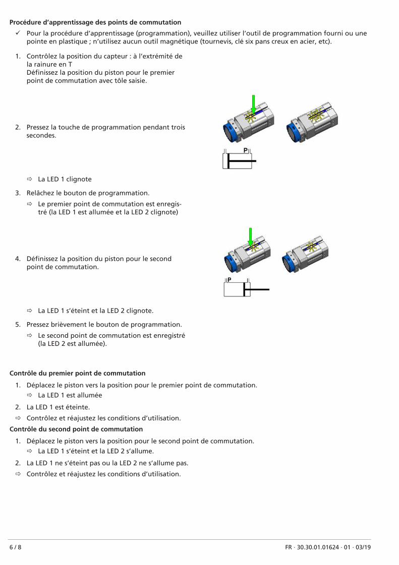
Procédure d’apprentissage des points de commutation
ü Pour la procédure d’apprentissage (programmation), veuillez utiliser l’outil de programmation fourni ou unepointe en plastique ; n’utilisez aucun outil magnétique (tournevis, clé six pans creux en acier, etc).
1. Contrôlez la position du capteur : à l’extrémité dela rainure en TDéfinissez la position du piston pour le premierpoint de commutation avec tôle saisie.
2. Pressez la touche de programmation pendant troissecondes.
ð La LED 1 clignote
3. Relâchez le bouton de programmation.
ð Le premier point de commutation est enregis-tré (la LED 1 est allumée et la LED 2 clignote)
4. Définissez la position du piston pour le secondpoint de commutation.
ð La LED 1 s’éteint et la LED 2 clignote.
5. Pressez brièvement le bouton de programmation.
ð Le second point de commutation est enregistré(la LED 2 est allumée).
Contrôle du premier point de commutation
1. Déplacez le piston vers la position pour le premier point de commutation.
ð La LED 1 est allumée
2. La LED 1 est éteinte.
ð Contrôlez et réajustez les conditions d’utilisation.
Contrôle du second point de commutation
1. Déplacez le piston vers la position pour le second point de commutation.
ð La LED 1 s’éteint et la LED 2 s’allume.
2. La LED 1 ne s’éteint pas ou la LED 2 ne s’allume pas.
ð Contrôlez et réajustez les conditions d’utilisation.
6 / 8 FR · 30.30.01.01624 · 01 · 03/19

6 EntretienLe capteur ne nécessite aucune maintenance.
Nous recommandons :
1. de nettoyer régulièrement les surfaces des LED.
2. de contrôler régulièrement le raccord fileté et la fiche de raccordement.
7 Pièces de rechange et d’usureRéf. article Type Désignation Catégorie
10.01.17.00509 Vis ZUB SGM-S NAEH-SCHA Vis Pièce de rechange
10.01.17.00510 Broche ZUB SGM-S NAEH-SCHA Broche en plastique Pièce de rechange
4 Lors du serrage de la vis de fixation, respectez le couple maximal de 0,2 +/- 0,05 Nm.
8 Élimination du capteur1. Vous êtes tenu d’éliminer le produit de manière conforme après un remplacement ou la mise hors service dé-
finitive.
2. Veuillez respecter les directives nationales et les obligations légales en vigueur relatives à la réduction et aurecyclage des déchets.
9 Configuration IO-Link possible uniquement pour la variante PNP
Voir également à ce sujet
2 Schmalz Näherungsschalter Data Dictionary 21.10.01.00118_00.pdf [} 8]
FR · 30.30.01.01624 · 01 · 03/19 7 / 8

IO�Link Data Dictionary magnetic switch21.10.01.00118/00 05.04.2018
J. Schmalz GmbH
Johannes-Schmalz-Str.1
D 72293 Glatten
Tel.: +49(0)7443/2403-0
Fax: +49(0)7443/2403-259
1 Boolean ro Logic state of switch point 2
0 Boolean ro Logic state of switch point 1
Subindex
dec hex dec
�
16 0x0010 0 64 bytes ro J. SCHMALZ GMBH Manufacturer designation
18 0x0012 0 64 bytes ro SMAGN S051 General product name
21 0x0015 0 16 bytes ro Serial number
22 0x0016 0 64 bytes ro 1.10 Hardware revison
23 0x0017 0 64 bytes ro 2.42 Firmware revision
24 0x0018 0 16 bytes rw User string to store location or tooling information
�
�
2 0x0002 0 1 byte 160, 161, 163, 164 wo
0xA0 (dec 160): teaching of switch point 1
0xA1 (dec 161): teaching of switch point 2
0xA3 (dec 163): global key lock
0xA4 (dec 164): global key unlock
�144 0x0090 0 8 bytes ro teached parameter of switch point 1
145 0x0091 0 8 bytes ro teached parameter of switch point 2
146 0x0092 1 1 byte 1 : 5 rw 1
146 0x0092 2 1 byte 1 : 5 rw 1
147 0x0093 0 1 byte ro 1
148 0x0094 0 1 byte ro 0
0...127 teach button not locked
128 teach button locked
129...255 teach button not locked
�
�40 0x0028 0 1 byte ro Copy of currently active process data input
IO�Link Implementation
Process Data
Remark
Switching Point 2
Name
234 (0x00EA)
1179758 (0x12006E)
Yes
1.0
Device ID
SIO�Mode
38.4 kBit/sec (COM2)
2.3 ms
1 bytes
Switching Point 1
Process Data Input
IO�Link Revision
Vendor ID
Process Data Input
Process Data Output
IO�Link Bitrate
Minimum Cycle Time
Teach Button Status
Identification
Firmware Revision
Application Specific Tag
Process Settings
Device Settings
Hardware Revision
Tolerance Level SP1
Vendor Name
Product Name
System Command
Monitoring
Process Data In Copy
Observation
Tolerance Level Default
Value Range
Bits
Display
Appearance
Tolerance Level SP2
ISDU Index
� Device Management
PD In Byte 0
None
Special Values
Parameter
Teach parameter SP1
Teach parameter SP2
Data Type Access
ISDU Parameters
RemarkDefault Value
Serial Number
Parameter
Size Access
J. Schmalz GmbH 1 of 1 magnetic switch Data Dictionary

Interruttore di prossimità per ventosa magnetica
Manuale d’uso
Nota
Il Manuale d’uso è stato redatto in lingua tedesca. Conservare il manuale per riferimento futuro. Con riserva dimodifiche tecniche, refusi ed errori.
Editore
© J. Schmalz GmbH, 03/19
La presente pubblicazione è protetta dai diritti d’autore. I diritti derivanti restano all’azienda J. Schmalz GmbH. Lariproduzione della pubblicazione o di parti della stessa è consentita solamente entro i limiti definiti dalle disposi-zioni della legge sul diritto d'autore. È vietato modificare o abbreviare la pubblicazione senza espressa autorizza-zione scritta dell’azienda J. Schmalz GmbH.
J. Schmalz GmbH · Johannes-Schmalz-Str. 1 D-72293 Glatten T: +49 7443 2403-0
IT · 30.30.01.01624 · 01 · 03/19

1 Informazioni importanti
1.1 Note per l’utilizzo di questo documentoLa J. Schmalz GmbH sarà indicata in questo Manuale d’uso in generale con il nome Schmalz.
Questo Manuale d’uso contiene note e informazioni importanti che riguardano le diverse fasi di funzionamentodel prodotto:
• Trasporto, immagazzinamento, messa in funzione e messa fuori servizio
• Funzionamento sicuro, interventi di manutenzione necessari, eliminazione di eventuali guasti
Il Manuale d’uso descrive il prodotto al momento della consegna da parte di Schmalz.
1.2 Simbolo
Questo simbolo fa riferimento a informazioni importanti e utili.
ü Questo simbolo fa riferimento a una condizione che deve essere soddisfatta prima di iniziare un intervento.
4 Questo simbolo fa riferimento a un’operazione da eseguire.
ð Questo simbolo fa riferimento al risultato di un’operazione.
Le operazioni che prevedono più passi sono numerate:
1. Prima operazione da eseguire.
2. Seconda operazione da eseguire.
2 Sicurezza
2.1 Nota di sicurezzaIl prodotto viene impiegato in connessione a un sistema di movimentazione automatizzato (portale / robot). Perquesto motivo, oltre alle note di sicurezza qui indicate, valgono anche le norme di sicurezza del sistema a cui il pro-dotto è collegato.
2.2 La documentazione tecnica fa parte del prodotto
1. Seguire le indicazioni di questa documentazione per garantire il funzionamento corretto e sicuro.
2. Conservare la documentazione tecnica nelle vicinanze del prodotto. Deve essere sempre accessibile per il per-sonale.
3. Consegnare la documentazione tecnica all’utente successivo.
ð L’inosservanza delle istruzioni di questo Manuale d’uso può causare lesioni gravi!
ð Per i danni e i malfunzionamenti derivanti dall’inosservanza delle istruzioni, l'azienda Schmalz non si assumealcuna responsabilità.
Se dopo la lettura della documentazione tecnica avete ancora delle domande, vi invitiamo a rivolgervi all‘Assisten-za di Schmalz-sotto:
www.schmalz.com/services
2.3 Utilizzo conforme alle istruzioniL’interruttore di prossimità serve per il rilevamento dei due fine corsa dei cilindri magnetici. Solo la variante PNPpuò essere letta e impostata tramite IO-Link.
Questo dispositivo è stato sviluppato, prodotto e realizzato esclusivamente per le applicazioni industriali e com-merciali. È escluso un impiego privato.
L’osservanza dei dati tecnici, delle istruzioni di montaggio ed esercizio di questo manuale fanno parte dell’utilizzoconforme alle istruzioni.
2.4 Qualifica del personaleIl personale non qualificato non è in grado di riconoscere i rischi e quindi è esposto a pericoli maggiori!
1. Tutti gli interventi sull'impianto elettrico devono essere eseguiti unicamente da elettricisti qualificati.
2. I lavori di montaggio e regolazione devono essere eseguiti solo da personale specializzato.
2 / 8 IT · 30.30.01.01624 · 01 · 03/19

3 Dati tecniciTensione di alimentazione UV DC 12…30 V
Consumo di corrente (non in funzione) I ≤ 15 mA
Corrente continua Ia ≤ 100 mA
Uscita di commutazione PNP/NPN
Funzione di uscita Normalmente aperto
Cavo di connessione M12x1 L=0,3 m
EMV EN 60 947-5-2
Grado di protezione IP 67
Temperatura ambiente -20..+75
4 Descrizione del prodotto
4.1 Dimensioni e denominazione
1 Vite di fissaggio
5
6
2 LED 2 - deposito
3 Pulsante teach
4 LED 1 - presa
5 Collegamento elettrico M12x1
6 Centro del sensore
4.2 Collegamento elettrico
Variante PNP NPN
schema elettri-co
Us
Q1
Q2GNDs
Us
Q1
Q2GNDs
Spina M12-1 Pin Colore trefoli Simbolo Funzione
1 Marrone US Tensione di alimentazione
2 Bianco Q1 Uscita segnale 1 (LED 2)
3 Blu GNDS Massa
4 Nero Q2 Uscita segnale 2 (LED 1)
IT · 30.30.01.01624 · 01 · 03/19 3 / 8

4.3 Varianti
Numero articolo Denominazione Accessori per Pezzo di ricambioper
10.01.17.00199 NAEH-SCHA SMAGN-PNP S051 SGM-HP, SGM-SV, SGM-HD-SV SGM-S, SGM-HD-S
10.01.17.00215 NAEH-SCHA SMAGN-PNP S050 SGM-HP, SGM-SV, SGM-HD-SV SGM-S, SGM-HD-S
10.01.17.00447 MOD-SENS NAEH SGM-HP-20-PNP SGM-HP 20 −
10.01.17.00448 MOD-SENS NAEH SGM-HP-20-NPN SGM-HP 20 −
5 Installazione
5.1 Indicazioni per l'installazione
La ventosa magnetica della serie SGM-HT-HP è dotata di sensori a causa del suo impiego ad alte tempe-rature. La ventosa magnetica della serie standard SGM / SGM-HD non può essere utilizzata con un sen-sore.
Per l’installazione sicura bisogna fare attenzione alle seguenti istruzioni:
• Utilizzare solo agli attacchi e i blocchi di fissaggio previsti.
• Proteggere il sensore dall’effetto meccanico (distacco). Provvedere allo scarico della trazione del cavo del sen-sore!
• Prima di collegare il sensore interrompere l’alimentazione di tensione e dell’aria.
• Fino alle varianti SGM-S / SGM-HD-S il sensore non viene fornito già con la procedura teach eseguita.
• Le condizioni ambientali (montaggio, campi magnetici ecc.) possono avere un impatto sul sensore. Per questomotivo potrebbe essere necessario eseguire nuovamente la funzione teach dopo l’installazione.
• Dopo l’installazione del sensore bisogna eseguire sempre la funzione teach.
• Eseguire la funzione teach con il pezzo da prelevare.
5.2 MontaggioLa posizione di montaggio del sensore è a discrezione dell'utente.
Per garantire un funzionamento perfetto della pinza di presa ed evitare guasti che possano compromettere il fun-zionamento del sensore, osservare le indicazioni di montaggio seguenti:
• Utilizzare elementi di fissaggio e similari in materiale non magnetizzabile (alluminio, plastica...).
• È necessario controllare a intervalli regolari il corretto alloggiamento del sensore nella scanalatura. Questovale soprattutto in caso di impiego in processi operativi rapidi e soggetti a vibrazioni.
• Forti campi magnetici possono compromettere il funzionamento del sensore. Pertanto, in ogni singolo casodeve essere verificata separatamente l'idoneità all'uso del sensore, ad es. in prossimità di impianti di saldatu-ra.
• Evitare oggetti magnetizzabili nell'ambiente in cui si trova il sensore o disporli a distanza sufficiente. Osserva-re le distanze minime specificate qui di seguito!
• Il sensore, la scanalatura sensore e la pinza devono essere controllati periodicamente per identificare delle im-purità ferromagnetiche (per es. sfridi) e quindi essere puliti se necessario.
4 / 8 IT · 30.30.01.01624 · 01 · 03/19

Distanze minime dagli oggetti magnetizzabili
Tipo SGM-HP
Sensore
20 30 40 50
Direzione A/B/C/D A/B/C/D A/B/C/D A/B/C/D
Distanza minima[mm]. racc.
20 20 20 20
Tipo SGM-(HD-)S / SGM-(HD-)SV
Sensore
30 40 50 70
Direzione A/B/C/D B B B
Distanza minima [mm]racc.
15 5 5 5
Distanza di 2 SGM-Sper bloccaggio latera-le (2 pinze di presa af-fiancate) e funziona-mento non sincroniz-zato [mm]
12 0 0 0
Messa in funzione del sensore durante la prima installazione o in caso di nuova regolazione
4 Posizionare il sensore al centro della scanalatura Te spingere fino in fondo ricordando che il sensoredeve rimanere al centro.
4 Avvitare saldamente il sensore con un cacciavite(coppia: 0,2 +/- 0,05 Nm).
4 Inserire la spina M12x1 e attivare l’alimentazione di funzionamento.
IT · 30.30.01.01624 · 01 · 03/19 5 / 8

Procedura teach-in dei punti di commutazione
ü Per la procedura teach-in utilizzare l’apposito strumento o una punta di plastica; non utilizzare alcun utensilemagnetico (cacciavite, chiave a brugola in acciaio ecc.).
1. Controllare la posizione del sensore: All’estremitàdella scanalatura TDefinire la posizione del pistone per il primo puntodi commutazione utilizzando la lamiera in dotazio-ne.
2. Premere il pulsante teach per 3 secondi.
ð Il LED 1 lampeggia
3. Rilasciare il pulsante teach.
ð Il primo punto di commutazione è memorizza-to (il LED 1 è acceso e il LED 2 lampeggia)
4. Definire la posizione del pistone per il secondopunto di commutazione.
ð Il LED 1 si spegne e il LED 2 lampeggia.
5. Premere brevemente il pulsante teach.
ð Il secondo punto di commutazione è memoriz-zato (il LED 2 è acceso).
Controllo 1 Punto di commutazione
1. Muovere il pistone in posizione per il primo punto di commutazione.
ð LED 1 si accende
2. LED 1 non si accende
ð Verificare le condizioni di impiego e regolare se necessario.
Controllo 2 Punto di commutazione
1. Muovere il pistone in posizione per il secondo punto di commutazione.
ð Il LED 1 si spegne e il LED 2 si accende.
2. Se il LED 1 non si spegne e il LED 2 non si accende.
ð Verificare le condizioni di impiego e regolare se necessario.
6 / 8 IT · 30.30.01.01624 · 01 · 03/19

6 ManutenzioneIl sensore non richiede manutenzione.
Consigliamo:
1. Pulire regolarmente le superfici dei LED.
2. Controllare il raccordo filettato e il collegamento a spina.
7 Pezzi di ricambio e parti soggette ad usuraN. articolo Tipo Denominazione Art
10.01.17.00509 Vite ZUB SGM-S NAEH-SCHA Vite Pezzo di ricambio
10.01.17.00510 PIN ZUB SGM-S NAEH-SCHA PIN di plastica Pezzo di ricambio
4 Per il serraggio della vite di fissaggio fare attenzione alla coppia massima di serraggio 0,2 +/- 0,05 Nm.
8 Smaltimento del sensore1. Dopo la sostituzione o la messa fuori servizio il prodotto deve essere smaltito come da istruzioni.
2. Osservare le direttive nazionali e gli obblighi di legge per lo smaltimento e la riduzione dei rifiuti.
9 Configurazione IO-Link solo per la variante PNP
Vedi a riguardo anche
2 Schmalz Näherungsschalter Data Dictionary 21.10.01.00118_00.pdf [} 8]
IT · 30.30.01.01624 · 01 · 03/19 7 / 8

IO�Link Data Dictionary magnetic switch21.10.01.00118/00 05.04.2018
J. Schmalz GmbH
Johannes-Schmalz-Str.1
D 72293 Glatten
Tel.: +49(0)7443/2403-0
Fax: +49(0)7443/2403-259
1 Boolean ro Logic state of switch point 2
0 Boolean ro Logic state of switch point 1
Subindex
dec hex dec
�
16 0x0010 0 64 bytes ro J. SCHMALZ GMBH Manufacturer designation
18 0x0012 0 64 bytes ro SMAGN S051 General product name
21 0x0015 0 16 bytes ro Serial number
22 0x0016 0 64 bytes ro 1.10 Hardware revison
23 0x0017 0 64 bytes ro 2.42 Firmware revision
24 0x0018 0 16 bytes rw User string to store location or tooling information
�
�
2 0x0002 0 1 byte 160, 161, 163, 164 wo
0xA0 (dec 160): teaching of switch point 1
0xA1 (dec 161): teaching of switch point 2
0xA3 (dec 163): global key lock
0xA4 (dec 164): global key unlock
�144 0x0090 0 8 bytes ro teached parameter of switch point 1
145 0x0091 0 8 bytes ro teached parameter of switch point 2
146 0x0092 1 1 byte 1 : 5 rw 1
146 0x0092 2 1 byte 1 : 5 rw 1
147 0x0093 0 1 byte ro 1
148 0x0094 0 1 byte ro 0
0...127 teach button not locked
128 teach button locked
129...255 teach button not locked
�
�40 0x0028 0 1 byte ro Copy of currently active process data input
IO�Link Implementation
Process Data
Remark
Switching Point 2
Name
234 (0x00EA)
1179758 (0x12006E)
Yes
1.0
Device ID
SIO�Mode
38.4 kBit/sec (COM2)
2.3 ms
1 bytes
Switching Point 1
Process Data Input
IO�Link Revision
Vendor ID
Process Data Input
Process Data Output
IO�Link Bitrate
Minimum Cycle Time
Teach Button Status
Identification
Firmware Revision
Application Specific Tag
Process Settings
Device Settings
Hardware Revision
Tolerance Level SP1
Vendor Name
Product Name
System Command
Monitoring
Process Data In Copy
Observation
Tolerance Level Default
Value Range
Bits
Display
Appearance
Tolerance Level SP2
ISDU Index
� Device Management
PD In Byte 0
None
Special Values
Parameter
Teach parameter SP1
Teach parameter SP2
Data Type Access
ISDU Parameters
RemarkDefault Value
Serial Number
Parameter
Size Access
J. Schmalz GmbH 1 of 1 magnetic switch Data Dictionary

Naderingsschakelaar voor magneetgrijper
Gebruikershandleiding
Aanwijzing
Deze Bedieningsinstructies is oorspronkelijk in het Duits opgesteld. Bewaar de instructies voor toekomstig ge-bruik. Technische wijzigingen, drukfouten en vergissingen voorbehouden.
Uitgever
© J. Schmalz GmbH, 03/19
Deze documentatie is auteursrechtelijk beschermd. De daarop gebaseerde rechten berusten bij J. Schmalz GmbH.Een vermenigvuldiging van de documentatie of delen van deze documentatie is uitsluitend binnen de grenzen vande wet- en regelgeving conform de auteurswet toegestaan. Wijzigen of inkorten van de documentatie is zonderde uitdrukkelijke, schriftelijke toestemming van J. Schmalz GmbH verboden.
J. Schmalz GmbH · Johannes-Schmalz-Str. 1 · D-72293 Glatten · T: +49 7443 2403-0
NL · 30.30.01.01624 · 01 · 03/19

1 Belangrijke informatie
1.1 Aanwijzing voor de omgang met dit documentDe J. Schmalz GmbH wordt in deze Bedieningsinstructies doorgaans Schmalz genoemd.
Deze Bedieningsinstructies bevat belangrijke aanwijzingen en informatie omtrent de verschillende gebruiksfasenvan het product:
• Transport, opslag, inbedrijfstelling en buitenbedrijfstelling
• Veilig gebruik, vereiste onderhoudswerkzaamheden, verhelpen van eventuele storingen
De Bedieningsinstructies beschrijft het product op het moment van levering door Schmalz.
1.2 Symbolen
Dit teken wijst op handige en belangrijke informatie.
ü Dit teken duidt op een voorwaarde waaraan voorafgaand aan een handeling moet zijn voldaan.
4 Dit teken geeft een uit te voeren handeling aan.
ð Dit teken staat voor het resultaat van een handeling.
Handelingen die uit meer dan één stap bestaan, zijn genummerd:
1. Eerste uit te voeren handeling.
2. Tweede uit te voeren handeling.
2 Veiligheid
2.1 VeiligheidsinstructieHet product wordt in combinatie met een geautomatiseerd handlingsysteem (portaal/robot) toegepast. Derhalvegelden naast de hier beschreven veiligheidsaanwijzingen tevens de veiligheidsvoorschriften van het betreffendesysteem!
2.2 De technische documentatie maakt deel uit van het product
1. Volg de aanwijzingen in de documenten voor een storingsvrij en veilig gebruik.
2. Bewaar de technische documentatie in de nabijheid van het product. Deze moet voor het personeel steedstoegankelijk zijn.
3. Geef de technische documentatie door aan volgende gebruikers.
ð Bij het negeren van de aanwijzingen in deze Bedieningsinstructies kunnen levensgevaarlijke verwondingenontstaan!
ð Voor schade en bedrijfsstoringen, ontstaan door het niet in acht nemen van de aanwijzingen, is Schmalz nietaansprakelijk.
Mocht u na het lezen van de technische documentatie nog vragen hebben, wendt u dan tot de Schmalz-service via:
www.schmalz.com/services
2.3 Gebruik volgens de voorschriftenDe naderingsschakelaar dient ter herkenning van twee eindstanden bij magnetische cilinders. Alleen de PNP-vari-ant kan per IO-link worden uitgelezen of ingesteld.
Dit apparaat is uitsluitend ontwikkeld, geconstrueerd en gebouwd voor industrieel en commercieel gebruik. Parti-culier gebruik is uitgesloten.
Tot gebruik volgens de voorschriften behoort het in acht nemen van de technische gegevens en de montage- engebruiksaanwijzingen in deze handleiding.
2.4 Kwalificatie personeelNiet gekwalificeerd personeel kan gevaren niet onderscheiden en is daardoor aan grotere risico's blootgesteld!
1. Elektrotechnische werkzaamheden of installaties mogen uitsluitend door gekwalificeerde elektrotechniciworden verricht.
2 / 8 NL · 30.30.01.01624 · 01 · 03/19

2. Montage- en instelwerkzaamheden mogen uitsluitend door desbetreffend gekwalificeerd personeel wordenuitgevoerd.
3 Technische gegevensVoedingsspanning UV DC 12…30 V
Stroomopname (niet ingeschakeld) I ≤ 15 mA
Continustroom Ia ≤ 100 mA
Schakeluitgang PNP/NPN
Uitgangsfunctie Maakcontact
Aansluitkabel M12x1 L=0,3m
EMV EN 60 947-5-2
Beschermingsgraad IP 67
Omgevingstemperatuur -20….+75
4 Productbeschrijving
4.1 Afmetingen en omschrijvingen
1 Bevestigingsschroef
5
6
2 Led 2 - neerzetten
3 Teach-toets
4 Led 1 - grijpen
5 Elektrische aansluiting M12x1
6 Midden sensor
4.2 Elektrische aansluiting
Variant PNP NPN
Schakelschema
Us
Q1
Q2GNDs
Us
Q1
Q2GNDs
Stekker M12-1 Pin Draadkleur Symbool Functie
1 Bruin US Voedingsspanning
2 Wit Q1 Signaaluitgang 1 (led 2)
3 Blauw GNDS Massa
4 Zwart Q2 Signaaluitgang 2 (led 1)
NL · 30.30.01.01624 · 01 · 03/19 3 / 8
4.3 Varianten
Artikelnummer Omschrijving Toebehoren voor Reserveonderdeelvoor
10.01.17.00199 NAEH-SCHA SMAGN-PNP S051 SGM-HP, SGM-SV, SGM-HD-SV SGM-S, SGM-HD-S
10.01.17.00215 NAEH-SCHA SMAGN-PNP S050 SGM-HP, SGM-SV, SGM-HD-SV SGM-S, SGM-HD-S
10.01.17.00447 MOD-SENS NAEH SGM-HP-20-PNP SGM-HP 20 −
10.01.17.00448 MOD-SENS NAEH SGM-HP-20-NPN SGM-HP 20 −
5 Installatie
5.1 Installatie-instructies
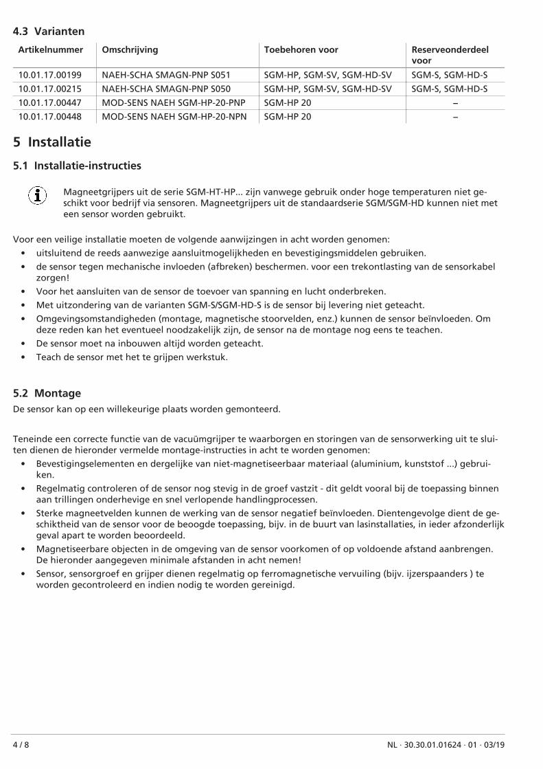
Magneetgrijpers uit de serie SGM-HT-HP... zijn vanwege gebruik onder hoge temperaturen niet ge-schikt voor bedrijf via sensoren. Magneetgrijpers uit de standaardserie SGM/SGM-HD kunnen niet meteen sensor worden gebruikt.
Voor een veilige installatie moeten de volgende aanwijzingen in acht worden genomen:
• uitsluitend de reeds aanwezige aansluitmogelijkheden en bevestigingsmiddelen gebruiken.
• de sensor tegen mechanische invloeden (afbreken) beschermen. voor een trekontlasting van de sensorkabelzorgen!
• Voor het aansluiten van de sensor de toevoer van spanning en lucht onderbreken.
• Met uitzondering van de varianten SGM-S/SGM-HD-S is de sensor bij levering niet geteacht.
• Omgevingsomstandigheden (montage, magnetische stoorvelden, enz.) kunnen de sensor beïnvloeden. Omdeze reden kan het eventueel noodzakelijk zijn, de sensor na de montage nog eens te teachen.
• De sensor moet na inbouwen altijd worden geteacht.
• Teach de sensor met het te grijpen werkstuk.
5.2 MontageDe sensor kan op een willekeurige plaats worden gemonteerd.
Teneinde een correcte functie van de vacuümgrijper te waarborgen en storingen van de sensorwerking uit te slui-ten dienen de hieronder vermelde montage-instructies in acht te worden genomen:
• Bevestigingselementen en dergelijke van niet-magnetiseerbaar materiaal (aluminium, kunststof ...) gebrui-ken.
• Regelmatig controleren of de sensor nog stevig in de groef vastzit - dit geldt vooral bij de toepassing binnenaan trillingen onderhevige en snel verlopende handlingprocessen.
• Sterke magneetvelden kunnen de werking van de sensor negatief beïnvloeden. Dientengevolge dient de ge-schiktheid van de sensor voor de beoogde toepassing, bijv. in de buurt van lasinstallaties, in ieder afzonderlijkgeval apart te worden beoordeeld.
• Magnetiseerbare objecten in de omgeving van de sensor voorkomen of op voldoende afstand aanbrengen.De hieronder aangegeven minimale afstanden in acht nemen!
• Sensor, sensorgroef en grijper dienen regelmatig op ferromagnetische vervuiling (bijv. ijzerspaanders ) teworden gecontroleerd en indien nodig te worden gereinigd.
4 / 8 NL · 30.30.01.01624 · 01 · 03/19
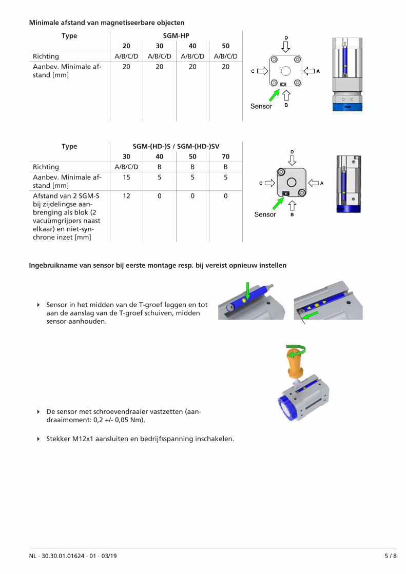
Minimale afstand van magnetiseerbare objecten
Type SGM-HP
Sensor
20 30 40 50
Richting A/B/C/D A/B/C/D A/B/C/D A/B/C/D
Aanbev. Minimale af-stand [mm]
20 20 20 20
Type SGM-(HD-)S / SGM-(HD-)SV
Sensor
30 40 50 70
Richting A/B/C/D B B B
Aanbev. Minimale af-stand [mm]
15 5 5 5
Afstand van 2 SGM-Sbij zijdelingse aan-brenging als blok (2vacuümgrijpers naastelkaar) en niet-syn-chrone inzet [mm]
12 0 0 0
Ingebruikname van sensor bij eerste montage resp. bij vereist opnieuw instellen
4 Sensor in het midden van de T-groef leggen en totaan de aanslag van de T-groef schuiven, middensensor aanhouden.
4 De sensor met schroevendraaier vastzetten (aan-draaimoment: 0,2 +/- 0,05 Nm).
4 Stekker M12x1 aansluiten en bedrijfsspanning inschakelen.
NL · 30.30.01.01624 · 01 · 03/19 5 / 8

Teach-in van de schakelpunten
ü Inbegrepen teach-in-gereedschap of kunststof pen gebruiken, geen magnetisch gereedschap (schroeven-draaier, stalen binnenzeskant, o.i.d.) gebruiken.
1. Sensorpositie controleren: Aan het einde van de T-groefMet de aangezogen metaalplaat de zuigerpositievoor het eerste schakelpunt vastleggen.
2. Teach-toets 3 seconden indrukken.
ð Led 1 knippert
3. Teach-toets loslaten.
ð Eerste schakelpunt is opgeslagen (led 1 brandten led 2 knippert)
4. De zuigerpositie voor het tweede schakelpunt vast-leggen.
ð Led 1 gaat uit en led 2 knippert.
5. De Teach-toets kort indrukken.
ð Het tweede schakelpunt is vastgelegd (led 2brandt).
Controle eerste schakelpunt
1. De zuiger in de juiste stand brengen voor het eerste schakelpunt.
ð Led 1 brandt
2. Led 1 brandt niet.
ð De gebruiksomstandigheden controleren en opnieuw afstellen.
Controle tweede schakelpunt
1. De zuiger in de juiste stand brengen voor het tweede schakelpunt.
ð Led 1 gaat uit en led 2 brandt.
2. Gaat led 1 niet uit resp. brandt led 2 niet.
ð De gebruiksomstandigheden controleren en opnieuw afstellen.
6 / 8 NL · 30.30.01.01624 · 01 · 03/19
6 OnderhoudDe sensor is onderhoudsvrij.
Wij adviseren:
1. de oppervlakken van de leds regelmatig te reinigen.
2. de schroef- en stekkerverbinding regelmatig te controleren.
7 Reserveonderdelen en aan slijtage onderhevige onderdelenArtikelnr. Type Omschrijving Art
10.01.17.00509 ZUB SGM-S NAEH-SCHA schroef Bout Reserveonderdeel
10.01.17.00510 ZUB SGM-S NAEH-SCHA PIN Kunststof pin Reserveonderdeel
4 Bij het aandraaien van de bevestigingsschroef het maximale aandraaimoment van 0,2 +/- 0,05 Nm in acht ne-men.
8 Sensor afvoeren1. Het product na vervanging of buitenbedrijfstelling volgens de voorschriften afvoeren.
2. Doe dit conform de landspecifieke richtlijnen en wettelijke verplichtingen aangaande afvoeren en voorko-men van afval.
9 IO-link-configuratie uitsluitend voor PNP-varianten
Zie ook:
2 Schmalz Näherungsschalter Data Dictionary 21.10.01.00118_00.pdf [} 8]
NL · 30.30.01.01624 · 01 · 03/19 7 / 8

IO�Link Data Dictionary magnetic switch21.10.01.00118/00 05.04.2018
J. Schmalz GmbH
Johannes-Schmalz-Str.1
D 72293 Glatten
Tel.: +49(0)7443/2403-0
Fax: +49(0)7443/2403-259
1 Boolean ro Logic state of switch point 2
0 Boolean ro Logic state of switch point 1
Subindex
dec hex dec
�
16 0x0010 0 64 bytes ro J. SCHMALZ GMBH Manufacturer designation
18 0x0012 0 64 bytes ro SMAGN S051 General product name
21 0x0015 0 16 bytes ro Serial number
22 0x0016 0 64 bytes ro 1.10 Hardware revison
23 0x0017 0 64 bytes ro 2.42 Firmware revision
24 0x0018 0 16 bytes rw User string to store location or tooling information
�
�
2 0x0002 0 1 byte 160, 161, 163, 164 wo
0xA0 (dec 160): teaching of switch point 1
0xA1 (dec 161): teaching of switch point 2
0xA3 (dec 163): global key lock
0xA4 (dec 164): global key unlock
�144 0x0090 0 8 bytes ro teached parameter of switch point 1
145 0x0091 0 8 bytes ro teached parameter of switch point 2
146 0x0092 1 1 byte 1 : 5 rw 1
146 0x0092 2 1 byte 1 : 5 rw 1
147 0x0093 0 1 byte ro 1
148 0x0094 0 1 byte ro 0
0...127 teach button not locked
128 teach button locked
129...255 teach button not locked
�
�40 0x0028 0 1 byte ro Copy of currently active process data input
IO�Link Implementation
Process Data
Remark
Switching Point 2
Name
234 (0x00EA)
1179758 (0x12006E)
Yes
1.0
Device ID
SIO�Mode
38.4 kBit/sec (COM2)
2.3 ms
1 bytes
Switching Point 1
Process Data Input
IO�Link Revision
Vendor ID
Process Data Input
Process Data Output
IO�Link Bitrate
Minimum Cycle Time
Teach Button Status
Identification
Firmware Revision
Application Specific Tag
Process Settings
Device Settings
Hardware Revision
Tolerance Level SP1
Vendor Name
Product Name
System Command
Monitoring
Process Data In Copy
Observation
Tolerance Level Default
Value Range
Bits
Display
Appearance
Tolerance Level SP2
ISDU Index
� Device Management
PD In Byte 0
None
Special Values
Parameter
Teach parameter SP1
Teach parameter SP2
Data Type Access
ISDU Parameters
RemarkDefault Value
Serial Number
Parameter
Size Access
J. Schmalz GmbH 1 of 1 magnetic switch Data Dictionary