Embed Size (px)
Citation preview
Der TouranElektrische AnlageKonstruktion und FunktionSelbststudienprogramm 307Service.2NEU AchtungHinweisDas Selbststudienprogramm stellt die Konstruktionund Funktion von Neuentwicklungen dar!Die Inhalte werden nicht aktualisiert.Aktuelle Prüf-, Einstell- und Reparaturanweisungenentnehmen Sie bitte der dafür vorgesehenenKD-Literatur!Die bisher nur in Oberklasse-Fahrzeugeneingesetzte Vernetzungstechnik wird jetzt auch inKompakt-Van‘s wie dem Volkswagen Tourangenutzt.Die dazu verwendeten Steuergeräteübernehmen Aufgaben, die bisher von Relaisund Schaltern ausgeführt wurden. Damit siediese Aufgaben effizient erfüllen können,müssen sie große Mengen an Informationen(Daten) untereinander austauschen. So einDatenaustausch würde beim Einsatzherkömmlicher Verfahren, z. B. der Nutzung vonLeitungsverbindungen, nur durch den Einsatzsehr vieler Kabel möglich.Damit die Leitungsverbindungen auf eineüberschaubare Anzahl begrenzt sind, setztVolkswagen verstärkt Datenbusverbindungenein.Dieses Selbststudienprogramm soll Ihnen helfen,das Vernetzungs-Konzept im Volkswagen Touranbesser kennen zu lernen.Es behandelt die Zuteilung der Steuergeräte zuden verschiedenen Datenbussystemen, dieEinbauorte der Relaisplätze, der Sicherungenund der Steuergeräte. Außerdem beschreibt esverschiedene Funktionen sowie Änderungen inder Diagnose.S307_0503
Auf einen BlickEinleitung . . . . . . . . . . . . . . . . . . . . . . . . . . . . . . . . . . . . . . . 4LIN-Datenbus . . . . . . . . . . . . . . . . . . . . . . . . . . . . . . . . . . . 16Bordnetz . . . . . . . . . . . . . . . . . . . . . . . . . . . . . . . . . . . . . . . 20
Diagnose-Interface für Datenbus . . . . . . . . . . . . . . . . . . . 24Steuergerät für Bordnetz . . . . . . . . . . . . . . . . . . . . . . . . . . 28Wischersystem Frontscheibe. . . . . . . . . . . . . . . . . . . . . . . . 38Wischersystem Heckscheibe. . . . . . . . . . . . . . . . . . . . . . . . 44Schalttafeleinsatz . . . . . . . . . . . . . . . . . . . . . . . . . . . . . . . . 46Wegfahrsicherung . . . . . . . . . . . . . . . . . . . . . . . . . . . . . . . 50Komfort- und Infotainmenteinstellungen . . . . . . . . . . . . . 54Beleuchtung . . . . . . . . . . . . . . . . . . . . . . . . . . . . . . . . . . . . . 55Service . . . . . . . . . . . . . . . . . . . . . . . . . . . . . . . . . . . . . . . . . 56Prüfen Sie Ihr Wissen . . . . . . . . . . . . . . . . . . . . . . . . . . . . . 584
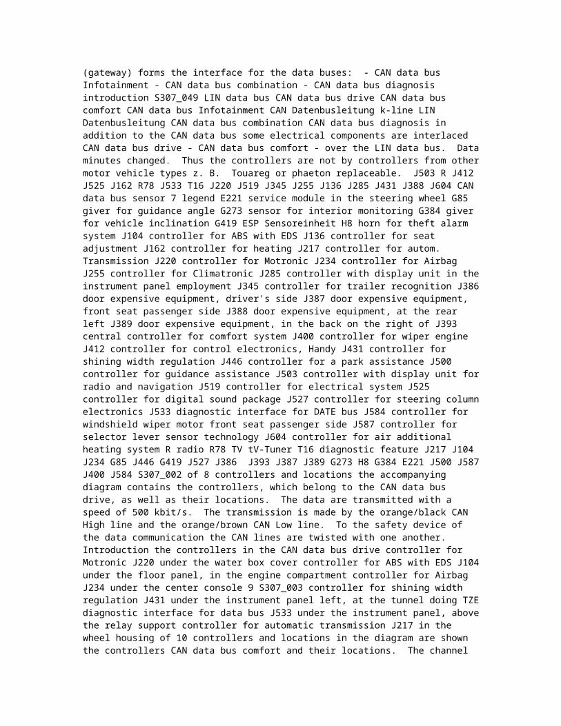
EinleitungEinbauorteDas Bordnetz des Touran ist dezentralaufgebaut. Aus diesem Grund befinden sich dieSicherungsboxen und die Relaisplätze anunterschiedlichen Orten im Fahrzeug.Die nebenstehende Darstellung zeigt dieunterschiedlichen Einbauorte.Die Sicherungsboxen und Relaisplätze im BordnetzVorsicherungsboxim Motorraum linksElektrik-Boxim Motorraum links5Sicherungsboxunter der Schalttafel linksS307_001Relaisträger am Steuergerät fürBordnetz, unter der Schalttafel linksRelaisträgerunter der Schalttafel links6Das Vernetzungs-KonzeptÜbersicht der vernetzten SteuergeräteDamit ein Datenaustausch zwischen denSteuergeräten möglich ist, sind sie überverschiedene Datenbussysteme miteinandervernetzt.Das Diagnose-Interface für Datenbus J533(Gateway) bildet die Schnittstelle für dieDatenbusse:- CAN-Datenbus Antrieb- CAN-Datenbus Komfort- CAN-Datenbus Infotainment- CAN-Datenbus Kombi- CAN-Datenbus Diagnose
EinleitungS307_049LIN-DatenbusCAN-DatenbusAntriebCAN-DatenbusKomfortCAN-DatenbusInfotainmentCAN-DatenbusleitungK-LeitungLIN-DatenbusleitungCAN-DatenbusKombiCAN-DatenbusDiagnoseZusätzlich zum CAN-Datenbus sindeinige elektrische Komponenten überden LIN-Datenbus vernetzt.Die Datenprotokolle haben sichgeändert. Dadurch sind dieSteuergeräte nicht durch Steuergeräteaus anderen Fahrzeugtypen z. B.Touareg oder Phaeton ersetzbar.J503RJ412J525J162R78J533T16J220J519J345J255J136J285J431J388J604CAN-DatenbusSensor7LegendeE221 Bedienungseinheit im LenkradG85 Geber für LenkwinkelG273 Sensor für InnenraumüberwachungG384 Geber für FahrzeugneigungG419 ESP-SensoreinheitH8 Signalhorn für DiebstahlwarnanlageJ104 Steuergerät für ABS mit EDSJ136 Steuergerät für Sitzverstellung
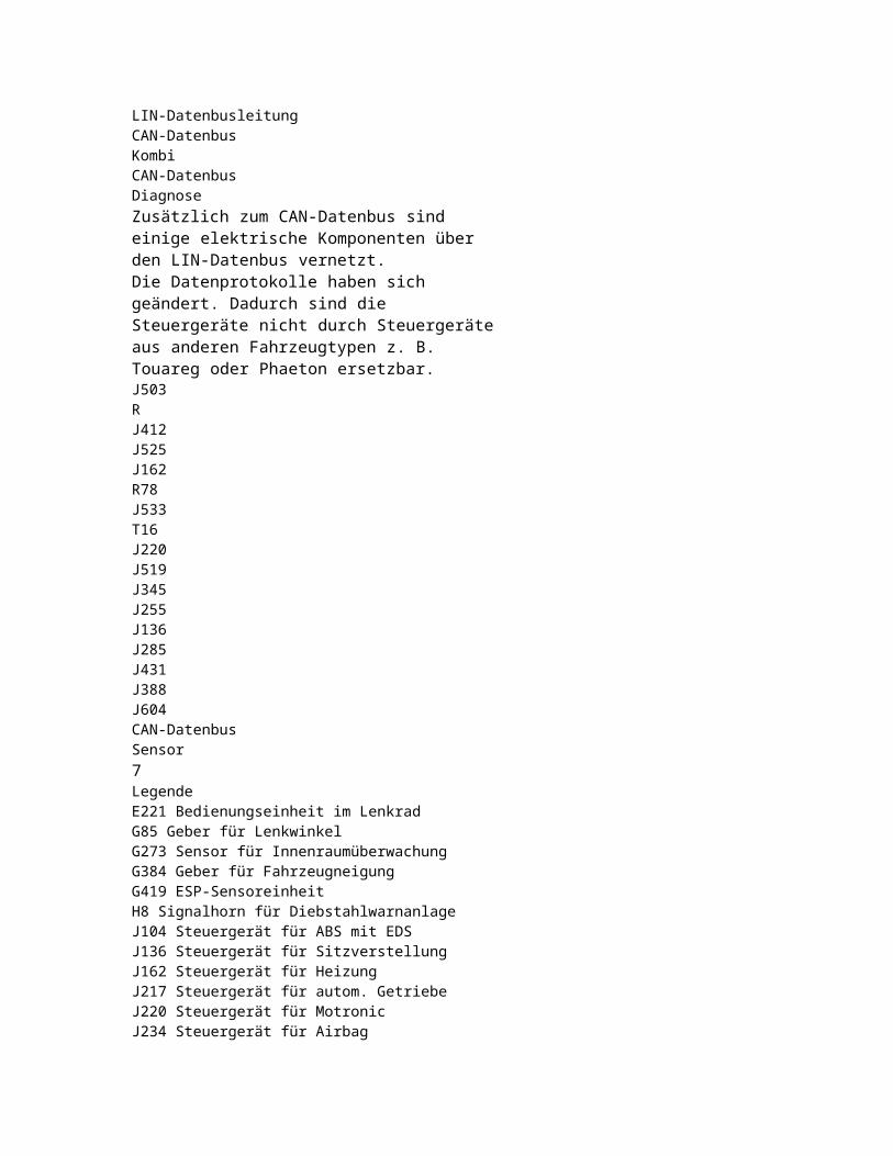
J162 Steuergerät für HeizungJ217 Steuergerät für autom. GetriebeJ220 Steuergerät für MotronicJ234 Steuergerät für AirbagJ255 Steuergerät für ClimatronicJ285 Steuergerät mit Anzeigeeinheit imSchalttafeleinsatzJ345 Steuergerät für AnhängererkennungJ386 Türsteuergerät, FahrerseiteJ387 Türsteuergerät, BeifahrerseiteJ388 Türsteuergerät, hinten linksJ389 Türsteuergerät, hinten rechtsJ393 Zentralsteuergerät für KomfortsystemJ400 Steuergerät für WischermotorJ412 Steuergerät für Bedienelektronik, HandyJ431 Steuergerät für LeuchtweitenregelungJ446 Steuergerät für EinparkhilfeJ500 Steuergerät für LenkhilfeJ503 Steuergerät mit Anzeigeeinheit für Radio undNavigationJ519 Steuergerät für BordnetzJ525 Steuergerät für Digitales Sound PaketJ527 Steuergerät für LenksäulenelektronikJ533 Diagnose-Interface für DatebusJ584 Steuergerät für ScheibenwischermotorBeifahrerseiteJ587 Steuergerät für WählhebelsensorikJ604 Steuergerät für LuftzusatzheizungR RadioR78 TV-TunerT16 DiagnoseanschlussJ217 J104J234 G85J446G419J527J386J393J387J389G273 H8 G384E221J500 J587J400 J584S307_0028Steuergeräte und EinbauorteDie nebenstehende Grafik enthält dieSteuergeräte, die zum CAN-Datenbus Antriebgehören, sowie deren Einbauorte.Die Daten werden mit einer Geschwindigkeit von500 kbit/s übertragen.Die Übertragung erfolgt über dieorange/schwarze CAN-High-Leitung und die
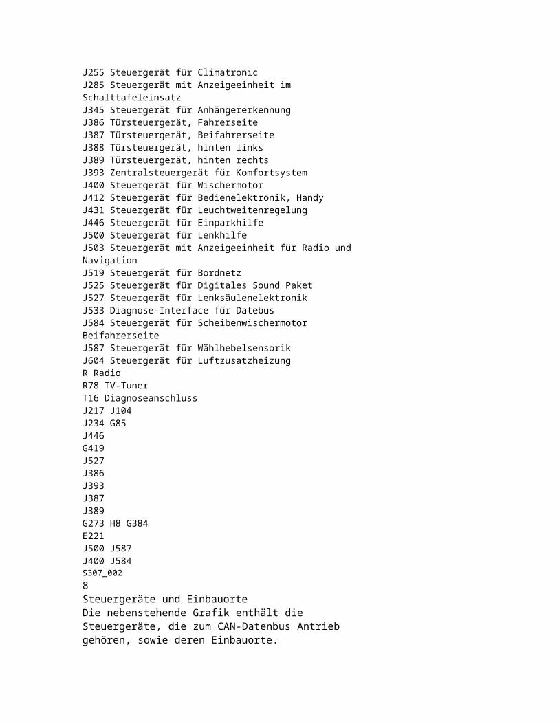
orange/braune CAN-Low-Leitung.Zur Sicherung der Datenübertragung sind dieCAN-Leitungen miteinander verdrillt.
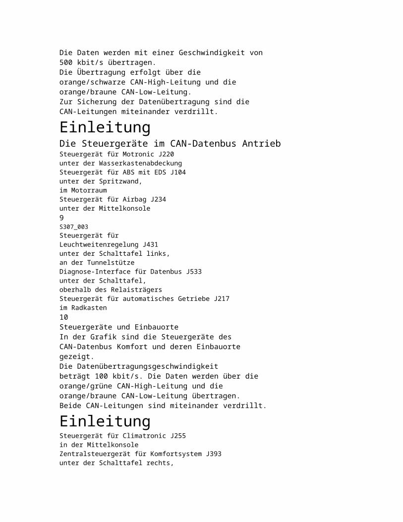
EinleitungDie Steuergeräte im CAN-Datenbus AntriebSteuergerät für Motronic J220unter der WasserkastenabdeckungSteuergerät für ABS mit EDS J104unter der Spritzwand,im MotorraumSteuergerät für Airbag J234unter der Mittelkonsole9S307_003Steuergerät fürLeuchtweitenregelung J431unter der Schalttafel links,an der TunnelstützeDiagnose-Interface für Datenbus J533unter der Schalttafel,oberhalb des RelaisträgersSteuergerät für automatisches Getriebe J217im Radkasten10Steuergeräte und EinbauorteIn der Grafik sind die Steuergeräte desCAN-Datenbus Komfort und deren Einbauortegezeigt.Die Datenübertragungsgeschwindigkeitbeträgt 100 kbit/s. Die Daten werden über dieorange/grüne CAN-High-Leitung und dieorange/braune CAN-Low-Leitung übertragen.Beide CAN-Leitungen sind miteinander verdrillt.
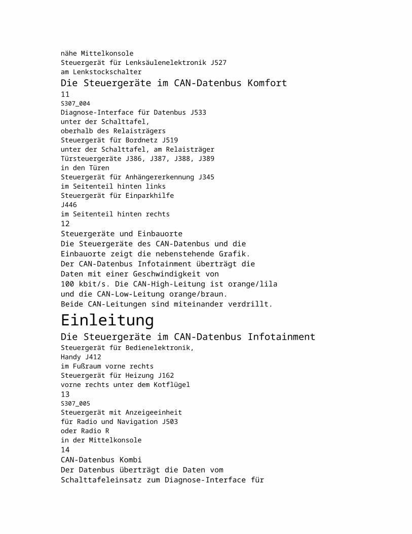
EinleitungSteuergerät für Climatronic J255in der MittelkonsoleZentralsteuergerät für Komfortsystem J393unter der Schalttafel rechts,nähe MittelkonsoleSteuergerät für Lenksäulenelektronik J527am LenkstockschalterDie Steuergeräte im CAN-Datenbus Komfort11S307_004Diagnose-Interface für Datenbus J533unter der Schalttafel,oberhalb des RelaisträgersSteuergerät für Bordnetz J519unter der Schalttafel, am RelaisträgerTürsteuergeräte J386, J387, J388, J389
in den TürenSteuergerät für Anhängererkennung J345im Seitenteil hinten linksSteuergerät für EinparkhilfeJ446im Seitenteil hinten rechts12Steuergeräte und EinbauorteDie Steuergeräte des CAN-Datenbus und dieEinbauorte zeigt die nebenstehende Grafik.Der CAN-Datenbus Infotainment überträgt dieDaten mit einer Geschwindigkeit von100 kbit/s. Die CAN-High-Leitung ist orange/lilaund die CAN-Low-Leitung orange/braun.Beide CAN-Leitungen sind miteinander verdrillt.
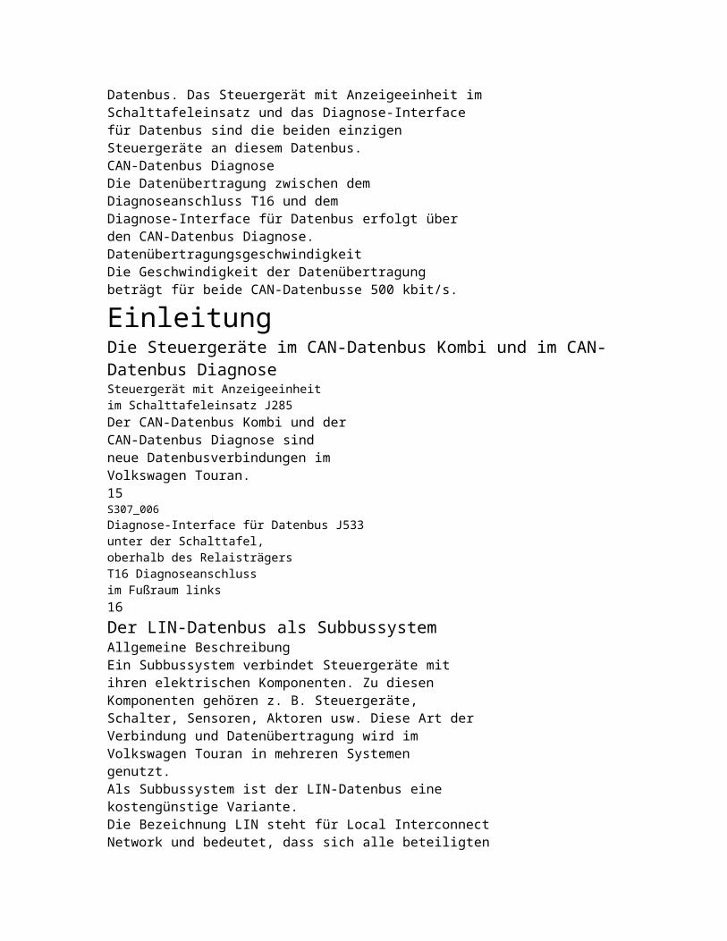
EinleitungDie Steuergeräte im CAN-Datenbus InfotainmentSteuergerät für Bedienelektronik,Handy J412im Fußraum vorne rechtsSteuergerät für Heizung J162vorne rechts unter dem Kotflügel13S307_005Steuergerät mit Anzeigeeinheitfür Radio und Navigation J503oder Radio Rin der Mittelkonsole14CAN-Datenbus KombiDer Datenbus überträgt die Daten vomSchalttafeleinsatz zum Diagnose-Interface fürDatenbus. Das Steuergerät mit Anzeigeeinheit imSchalttafeleinsatz und das Diagnose-Interfacefür Datenbus sind die beiden einzigenSteuergeräte an diesem Datenbus.CAN-Datenbus DiagnoseDie Datenübertragung zwischen demDiagnoseanschluss T16 und demDiagnose-Interface für Datenbus erfolgt überden CAN-Datenbus Diagnose.DatenübertragungsgeschwindigkeitDie Geschwindigkeit der Datenübertragungbeträgt für beide CAN-Datenbusse 500 kbit/s.
EinleitungDie Steuergeräte im CAN-Datenbus Kombi und im CAN-Datenbus DiagnoseSteuergerät mit Anzeigeeinheit
im Schalttafeleinsatz J285Der CAN-Datenbus Kombi und derCAN-Datenbus Diagnose sindneue Datenbusverbindungen imVolkswagen Touran.15S307_006Diagnose-Interface für Datenbus J533unter der Schalttafel,oberhalb des RelaisträgersT16 Diagnoseanschlussim Fußraum links16Der LIN-Datenbus als SubbussystemAllgemeine BeschreibungEin Subbussystem verbindet Steuergeräte mitihren elektrischen Komponenten. Zu diesenKomponenten gehören z. B. Steuergeräte,Schalter, Sensoren, Aktoren usw. Diese Art derVerbindung und Datenübertragung wird imVolkswagen Touran in mehreren Systemengenutzt.Als Subbussystem ist der LIN-Datenbus einekostengünstige Variante.Die Bezeichnung LIN steht für Local InterconnectNetwork und bedeutet, dass sich alle beteiligtenelektrischen Komponenten in einem bestimmtenbegrenzten Bereich des Fahrzeuges befinden.Es können mehrere LIN-Datenbussysteme ineinem Fahrzeug eingesetzt werden, diese führendann unterschiedliche Funktionen aus.Ein LIN-Datenbussystem besteht aus einemMaster-Steuergerät und einem oder mehrerenSlave-Steuergeräten.Das Master-Steuergerät ist, ausser mit denSlave-Steuergeräten über den CAN-Datenbus,auch mit den anderen Steuergeräten imFahrzeug vernetzt. So können Daten zu anderenLIN-Datenbussystemen und zu anderenCAN-Datenbus-Steuergeräten übertragenwerden.
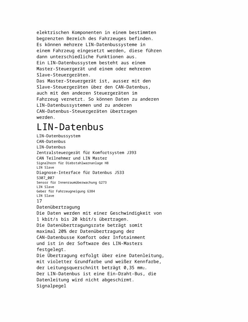
LIN-DatenbusLIN-DatenbussystemCAN-DatenbusLIN-DatenbusZentralsteuergerät für Komfortsystem J393CAN Teilnehmer und LIN MasterSignalhorn für Diebstahlwarnanlage H8LIN SlaveDiagnose-Interface für Datenbus J533
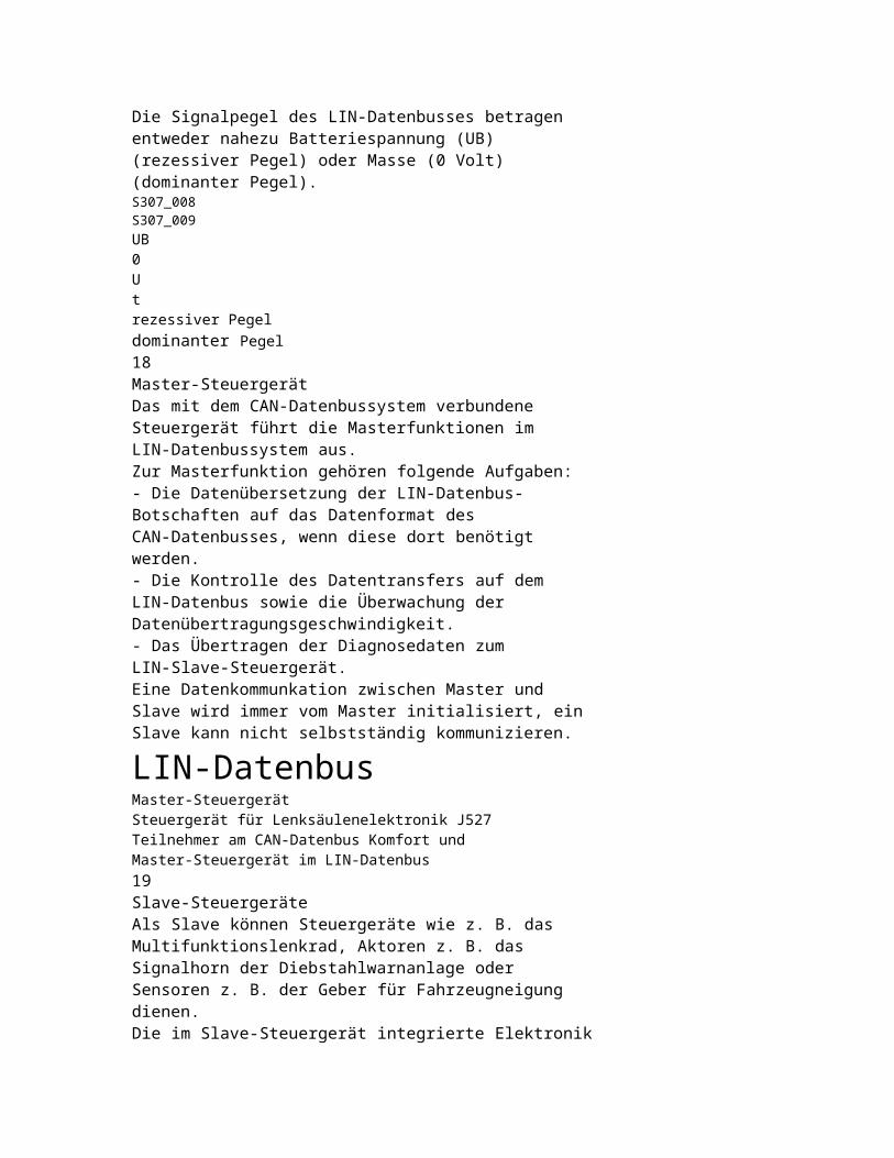
S307_007Sensor für Innenraumüberwachung G273LIN SlaveGeber für Fahrzeugneigung G384LIN Slave17DatenübertragungDie Daten werden mit einer Geschwindigkeit von1 kbit/s bis 20 kbit/s übertragen.Die Datenübertragungsrate beträgt somitmaximal 20% der Datenübertragung derCAN-Datenbusse Komfort oder Infotainmentund ist in der Software des LIN-Mastersfestgelegt.Die Übertragung erfolgt über eine Datenleitung,mit violetter Grundfarbe und weißer Kennfarbe,der Leitungsquerschnitt beträgt 0,35 mm2.Der LIN-Datenbus ist eine Ein-Draht-Bus, dieDatenleitung wird nicht abgeschirmt.SignalpegelDie Signalpegel des LIN-Datenbusses betragenentweder nahezu Batteriespannung (UB)(rezessiver Pegel) oder Masse (0 Volt)(dominanter Pegel).S307_008S307_009UB0Utrezessiver Pegeldominanter Pegel18Master-SteuergerätDas mit dem CAN-Datenbussystem verbundeneSteuergerät führt die Masterfunktionen imLIN-Datenbussystem aus.Zur Masterfunktion gehören folgende Aufgaben:- Die Datenübersetzung der LIN-Datenbus-Botschaften auf das Datenformat desCAN-Datenbusses, wenn diese dort benötigtwerden.- Die Kontrolle des Datentransfers auf demLIN-Datenbus sowie die Überwachung derDatenübertragungsgeschwindigkeit.- Das Übertragen der Diagnosedaten zumLIN-Slave-Steuergerät.Eine Datenkommunkation zwischen Master undSlave wird immer vom Master initialisiert, einSlave kann nicht selbstständig kommunizieren.
LIN-Datenbus
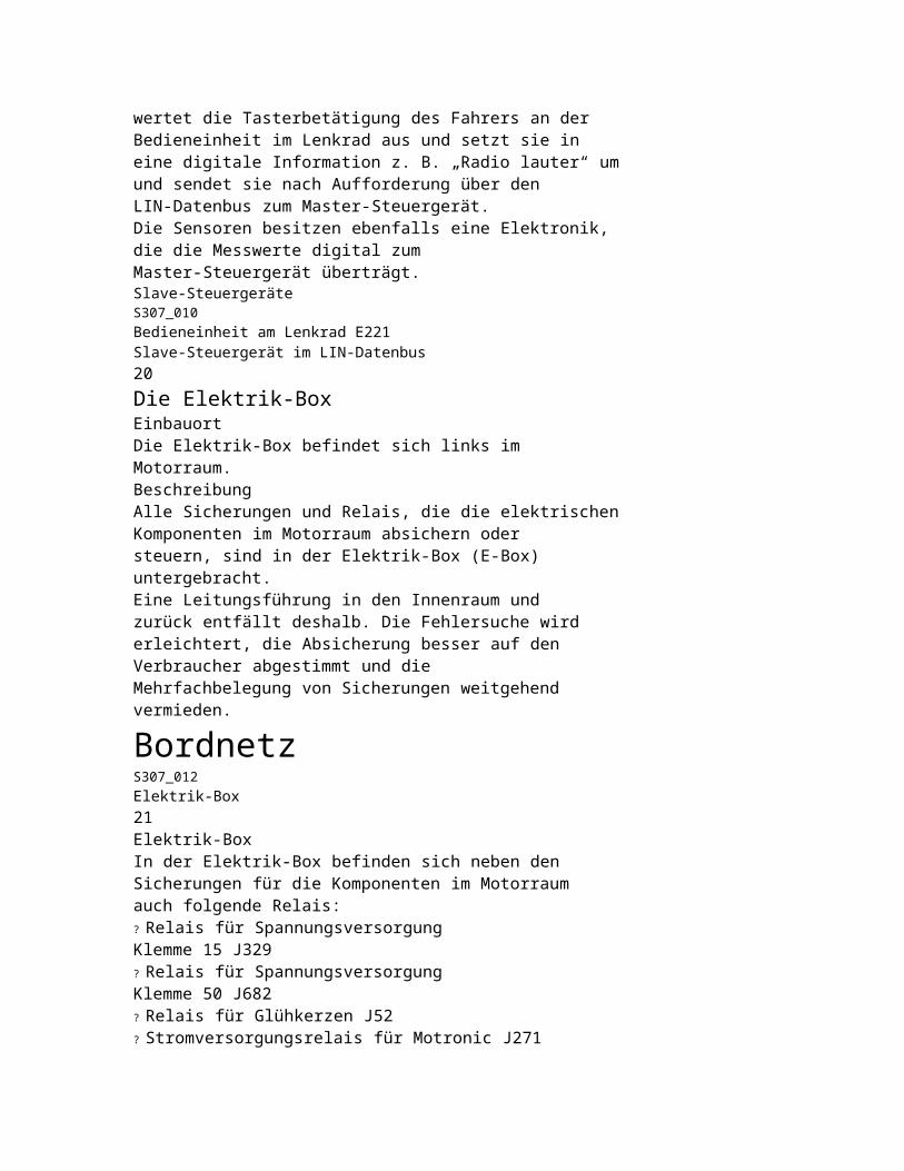
Master-SteuergerätSteuergerät für Lenksäulenelektronik J527Teilnehmer am CAN-Datenbus Komfort undMaster-Steuergerät im LIN-Datenbus19Slave-SteuergeräteAls Slave können Steuergeräte wie z. B. dasMultifunktionslenkrad, Aktoren z. B. dasSignalhorn der Diebstahlwarnanlage oderSensoren z. B. der Geber für Fahrzeugneigungdienen.Die im Slave-Steuergerät integrierte Elektronikwertet die Tasterbetätigung des Fahrers an derBedieneinheit im Lenkrad aus und setzt sie ineine digitale Information z. B. „Radio lauter“ umund sendet sie nach Aufforderung über denLIN-Datenbus zum Master-Steuergerät.Die Sensoren besitzen ebenfalls eine Elektronik,die die Messwerte digital zumMaster-Steuergerät überträgt.Slave-SteuergeräteS307_010Bedieneinheit am Lenkrad E221Slave-Steuergerät im LIN-Datenbus20Die Elektrik-BoxEinbauortDie Elektrik-Box befindet sich links imMotorraum.BeschreibungAlle Sicherungen und Relais, die die elektrischenKomponenten im Motorraum absichern odersteuern, sind in der Elektrik-Box (E-Box)untergebracht.Eine Leitungsführung in den Innenraum undzurück entfällt deshalb. Die Fehlersuche wirderleichtert, die Absicherung besser auf denVerbraucher abgestimmt und dieMehrfachbelegung von Sicherungen weitgehendvermieden.
BordnetzS307_012Elektrik-Box21Elektrik-BoxIn der Elektrik-Box befinden sich neben denSicherungen für die Komponenten im Motorraumauch folgende Relais:? Relais für Spannungsversorgung
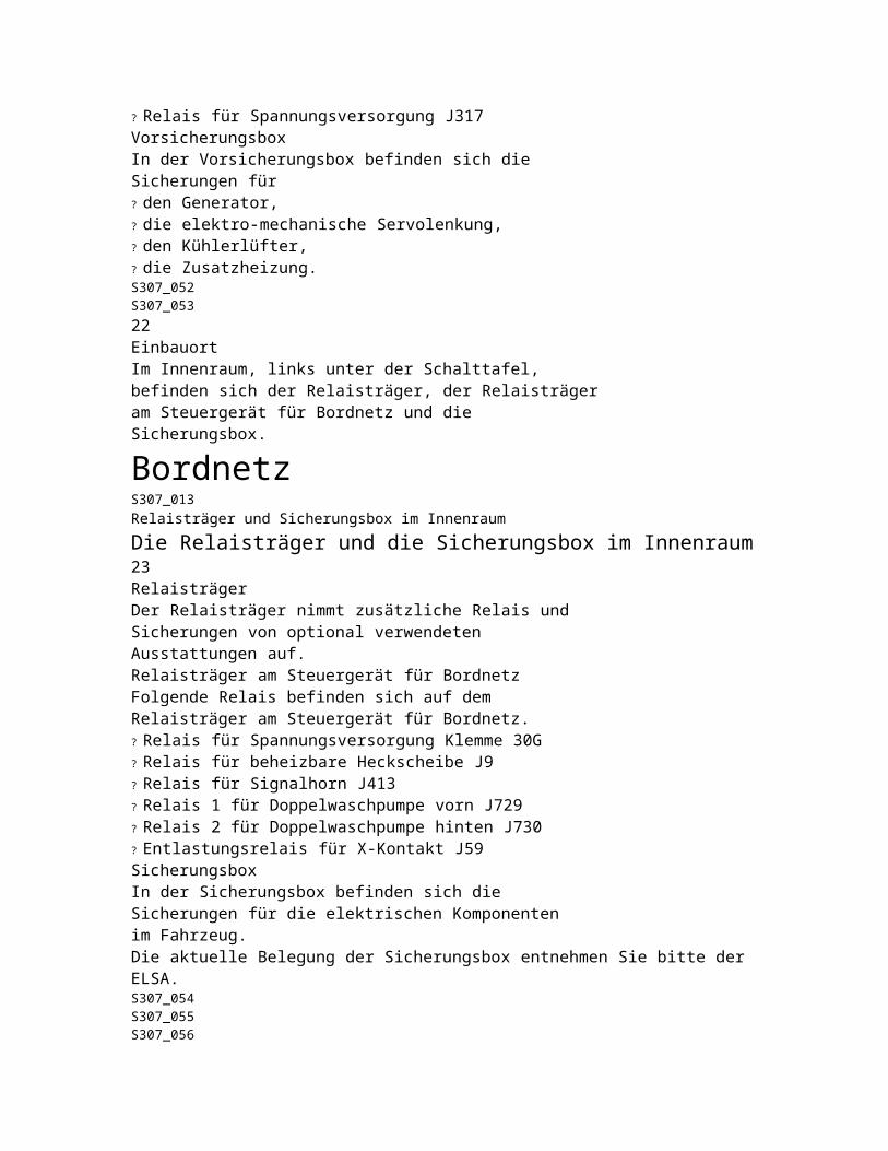
Klemme 15 J329? Relais für SpannungsversorgungKlemme 50 J682? Relais für Glühkerzen J52? Stromversorgungsrelais für Motronic J271? Relais für Spannungsversorgung J317VorsicherungsboxIn der Vorsicherungsbox befinden sich dieSicherungen für? den Generator,? die elektro-mechanische Servolenkung,? den Kühlerlüfter,? die Zusatzheizung.S307_052S307_05322EinbauortIm Innenraum, links unter der Schalttafel,befinden sich der Relaisträger, der Relaisträgeram Steuergerät für Bordnetz und dieSicherungsbox.
BordnetzS307_013Relaisträger und Sicherungsbox im InnenraumDie Relaisträger und die Sicherungsbox im Innenraum23RelaisträgerDer Relaisträger nimmt zusätzliche Relais undSicherungen von optional verwendetenAusstattungen auf.Relaisträger am Steuergerät für BordnetzFolgende Relais befinden sich auf demRelaisträger am Steuergerät für Bordnetz.? Relais für Spannungsversorgung Klemme 30G? Relais für beheizbare Heckscheibe J9? Relais für Signalhorn J413? Relais 1 für Doppelwaschpumpe vorn J729? Relais 2 für Doppelwaschpumpe hinten J730? Entlastungsrelais für X-Kontakt J59SicherungsboxIn der Sicherungsbox befinden sich dieSicherungen für die elektrischen Komponentenim Fahrzeug.Die aktuelle Belegung der Sicherungsbox entnehmen Sie bitte der ELSA.S307_054S307_055S307_056
24Beschreibung
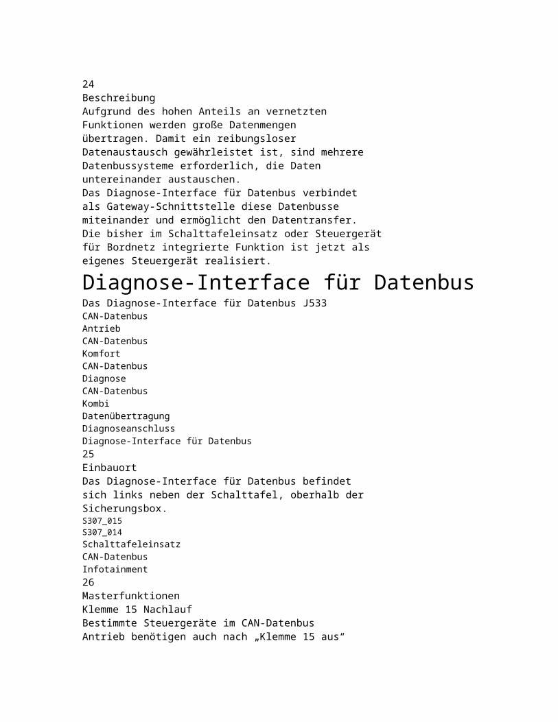
Aufgrund des hohen Anteils an vernetztenFunktionen werden große Datenmengenübertragen. Damit ein reibungsloserDatenaustausch gewährleistet ist, sind mehrereDatenbussysteme erforderlich, die Datenuntereinander austauschen.Das Diagnose-Interface für Datenbus verbindetals Gateway-Schnittstelle diese Datenbussemiteinander und ermöglicht den Datentransfer.Die bisher im Schalttafeleinsatz oder Steuergerätfür Bordnetz integrierte Funktion ist jetzt alseigenes Steuergerät realisiert.
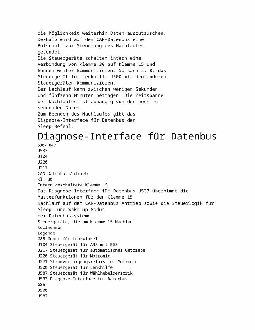
Diagnose-Interface für DatenbusDas Diagnose-Interface für Datenbus J533CAN-DatenbusAntriebCAN-DatenbusKomfortCAN-DatenbusDiagnoseCAN-DatenbusKombiDatenübertragungDiagnoseanschlussDiagnose-Interface für Datenbus25EinbauortDas Diagnose-Interface für Datenbus befindetsich links neben der Schalttafel, oberhalb derSicherungsbox.S307_015S307_014SchalttafeleinsatzCAN-DatenbusInfotainment26MasterfunktionenKlemme 15 NachlaufBestimmte Steuergeräte im CAN-DatenbusAntrieb benötigen auch nach „Klemme 15 aus“die Möglichkeit weiterhin Daten auszutauschen.Deshalb wird auf dem CAN-Datenbus eineBotschaft zur Steuerung des Nachlaufesgesendet.Die Steuergeräte schalten intern eineVerbindung von Klemme 30 auf Klemme 15 undkönnen weiter kommunizieren. So kann z. B. dasSteuergerät für Lenkhilfe J500 mit den anderenSteuergeräten kommunizieren.Der Nachlauf kann zwischen wenigen Sekunden
und fünfzehn Minuten betragen. Die Zeitspannedes Nachlaufes ist abhängig von den noch zusendenden Daten.Zum Beenden des Nachlaufes gibt dasDiagnose-Interface für Datenbus denSleep-Befehl.
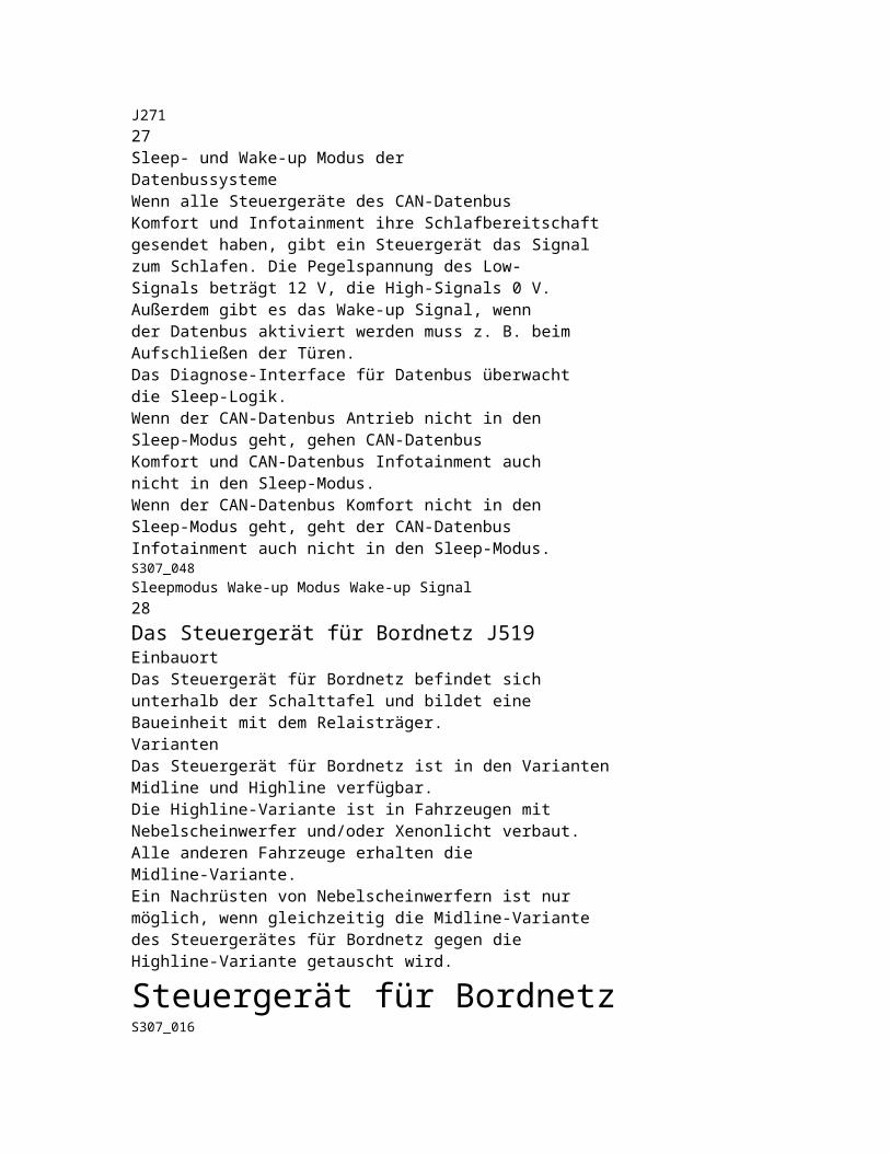
Diagnose-Interface für DatenbusS307_047J533J104J220J217CAN-Datenbus-AntriebKl. 30Intern geschaltete Klemme 15Das Diagnose-Interface für Datenbus J533 übernimmt die Masterfunktionen für den Klemme 15Nachlauf auf dem CAN-Datenbus Antrieb sowie die Steuerlogik für Sleep- und Wake-up Modusder Datenbussysteme.Steuergeräte, die am Klemme 15 NachlaufteilnehmenLegendeG85 Geber für LenkwinkelJ104 Steuergerät für ABS mit EDSJ217 Steuergerät für automatisches GetriebeJ220 Steuergerät für MotronicJ271 Stromversorgungsrelais für MotronicJ500 Steuergerät für LenkhilfeJ587 Steuergerät für WählhebelsensorikJ533 Diagnose-Interface für DatenbusG85J500J587J27127Sleep- und Wake-up Modus derDatenbussystemeWenn alle Steuergeräte des CAN-DatenbusKomfort und Infotainment ihre Schlafbereitschaftgesendet haben, gibt ein Steuergerät das Signalzum Schlafen. Die Pegelspannung des Low-Signals beträgt 12 V, die High-Signals 0 V.Außerdem gibt es das Wake-up Signal, wennder Datenbus aktiviert werden muss z. B. beimAufschließen der Türen.Das Diagnose-Interface für Datenbus überwachtdie Sleep-Logik.Wenn der CAN-Datenbus Antrieb nicht in denSleep-Modus geht, gehen CAN-DatenbusKomfort und CAN-Datenbus Infotainment auch
nicht in den Sleep-Modus.Wenn der CAN-Datenbus Komfort nicht in denSleep-Modus geht, geht der CAN-DatenbusInfotainment auch nicht in den Sleep-Modus.S307_048Sleepmodus Wake-up Modus Wake-up Signal28Das Steuergerät für Bordnetz J519EinbauortDas Steuergerät für Bordnetz befindet sichunterhalb der Schalttafel und bildet eineBaueinheit mit dem Relaisträger.VariantenDas Steuergerät für Bordnetz ist in den VariantenMidline und Highline verfügbar.Die Highline-Variante ist in Fahrzeugen mitNebelscheinwerfer und/oder Xenonlicht verbaut.Alle anderen Fahrzeuge erhalten dieMidline-Variante.Ein Nachrüsten von Nebelscheinwerfern ist nurmöglich, wenn gleichzeitig die Midline-Variantedes Steuergerätes für Bordnetz gegen dieHighline-Variante getauscht wird.
Steuergerät für BordnetzS307_016S307_017Die nachfolgend angegebenenZahlenwerte sind ca. Werte undkönnen abhängig von derLändervariante und der Softwarevariieren.Steuergerät für Bordnetz Relaisträger amSteuergerät für Bordnetz29Aufgaben:- Elektrisches Lastmanagement- FunktionsfreigabeDas Steuergerät für Bordnetz gibt die Funktiondes elektrischen Schiebe-Ausstelldaches frei.- Außenlichtsteuerung- Blinkersteuerung- Wischer, FrontscheibeWeiterleiten der Datenbussignale zumSteuergerät für Wischermotor- Wischer, Heckscheibe- Beheizbare HeckscheibeDie Ansteuerung der beheizbarenHeckscheibe erfolgt über das Steuergerät fürBordnetz, wenn der Taster für beheizbare
Heckscheibe betätigt wird und der Generatorausreichend Spannung erzeugt.- InnenlichtsteuerungDie Kl. 30G, über die die Innenleuchten mitSpannung versorgt werden, wird vomSteuergerät für Bordnetz beschaltet.- KulissenbeleuchtungDie Beleuchtung für Fußraum wirdpulsweitenmoduliert, entsprechend derStellung des Reglers für Beleuchtung - Schalterund Instrumente, vom Steuergerät für Bordnetzangesteuert.- KlemmensteuerungDas Steuergerät für Bordnetz steuert dieKlemme 75x über das Entlastungsrelais fürX-Kontakt.Die Klemme 15 über die Relais für SpannungsversorgungKl. 15 in der Elektrikbox und aufdem Relaisträger am Steuergerät für Bordnetz.Die Klemme 50 über die Relais fürSpannungsversorgung Kl. 50 in derElektrikbox.- Dimmung, InstrumentenbeleuchtungDer dimmbare Ausgang Kl. 58d versorgt diedimmbaren Schalter und Instrumente mitSpannung.- KraftstoffpumpenvorlaufBeim Öffnen der Fahrertür wird die elektrischeKraftstoffpumpe vom Steuergerät für Bordnetzmit Spannung versorgt. Nach dem Anspringendes Motors erfolgt die Versorgung über dasSteuergerät für Motorelektronik.- GeneratorvorerregungDie Vorerregung des Generators erfolgt überdas Steuergerät für Bordnetz.Das Steuergerät für Bordnetz schaltet und steuert folgende Funktionen:30Elektrisches LastmanagementDas elektrische Lastmanagement sorgt dafür,dass immer genügend elektrische Energie zumStarten in der Batterie vorhanden ist.Zu diesem Zweck werden elektrischeKomfortverbraucher abgeschaltet.Die technische Sicherheit bleibt erhalten.Das Steuergerät für Bordnetz wertet zurAbschaltung die Motordrehzahl,die Batteriespannung unddie Generatorlast über das DF-Signal(Dynamo Feld) aus.Aus diesen Informationen sowie der Information
über eingeschaltete Hochstromverbraucher mitkurzer Einschaltdauer führt das Steuergerät fürBordnetz eine Bewertung der Bordnetzlast durch.Aufgrund dieser Auswertung kann dasSteuergerät für Bordnetz die Anhebung derMotordrehzahl vom Motorsteuergerät fordern.Weiterhin kann die Abschaltung vonKomfortverbrauchern veranlasst werden.Für das Lastmanagement werden dreiverschiedene Betriebsarten erkannt.Betriebsart 1Klemme 15 ein undGenerator aktivMaßnahmen:Bei einer Batteriespannung unter 12,7 Voltfordert das Steuergerät für Bordnetz eineLeerlaufdrehzahlanhebung.Bei einer Batteriespannung unter 12,2 Voltwerden folgende Verbraucher abgeschaltet:- Beheizbare Sitze- Beheizbare Frontscheibe- Beheizbare Außenspiegel- Lenkradheizung- Fußraumbeleuchtung- Türinnengriffbeleuchtung- Reduzierung und Abschaltung der Climatronic- Infotainment Vorwarnung und Abschaltung
Steuergerät für Bordnetz31Betriebsart 2Klemme 15 ein undGenerator nicht aktivMaßnahmen:Bei einer Batteriespannung unter 12,2 Voltwerden folgende Verbraucher abgeschaltet:- Reduzierung und Abschaltung Klimaanlage- Fußraumbeleuchtung- Türinnengriffbeleuchtung- Ausstiegsleuchten- Leaving Home- Infotainment Vorwarnung und AbschaltungBetriebsart 3Klemme 15 aus undGenerator nicht aktivMaßnahmen:Bei einer Batteriespannung unter 11,8 Voltwerden folgende Verbraucher abgeschaltet:- Innenraumbeleuchtung
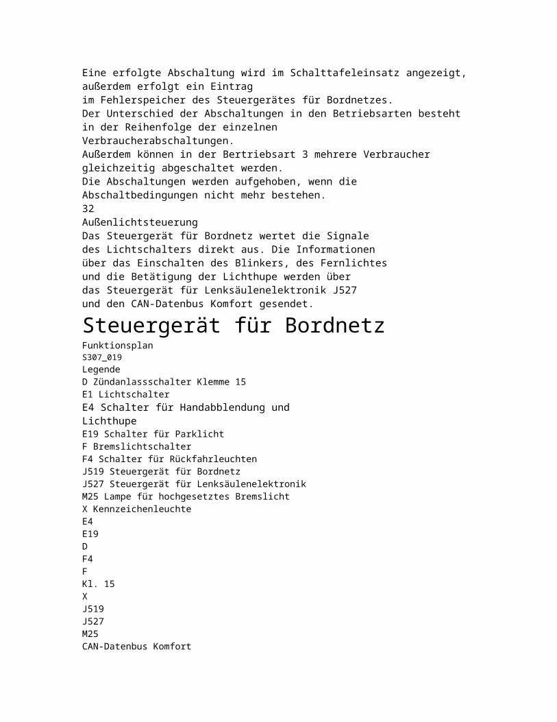
- Fußraumbeleuchtung- Türinnengriffbeleuchtung- Ausstiegsleuchten- Leaving Home- Infotainment z. B. RadioEine erfolgte Abschaltung wird im Schalttafeleinsatz angezeigt, außerdem erfolgt ein Eintragim Fehlerspeicher des Steuergerätes für Bordnetzes.Der Unterschied der Abschaltungen in den Betriebsarten besteht in der Reihenfolge der einzelnenVerbraucherabschaltungen.Außerdem können in der Bertriebsart 3 mehrere Verbraucher gleichzeitig abgeschaltet werden.Die Abschaltungen werden aufgehoben, wenn die Abschaltbedingungen nicht mehr bestehen.32AußenlichtsteuerungDas Steuergerät für Bordnetz wertet die Signaledes Lichtschalters direkt aus. Die Informationenüber das Einschalten des Blinkers, des Fernlichtesund die Betätigung der Lichthupe werden überdas Steuergerät für Lenksäulenelektronik J527und den CAN-Datenbus Komfort gesendet.
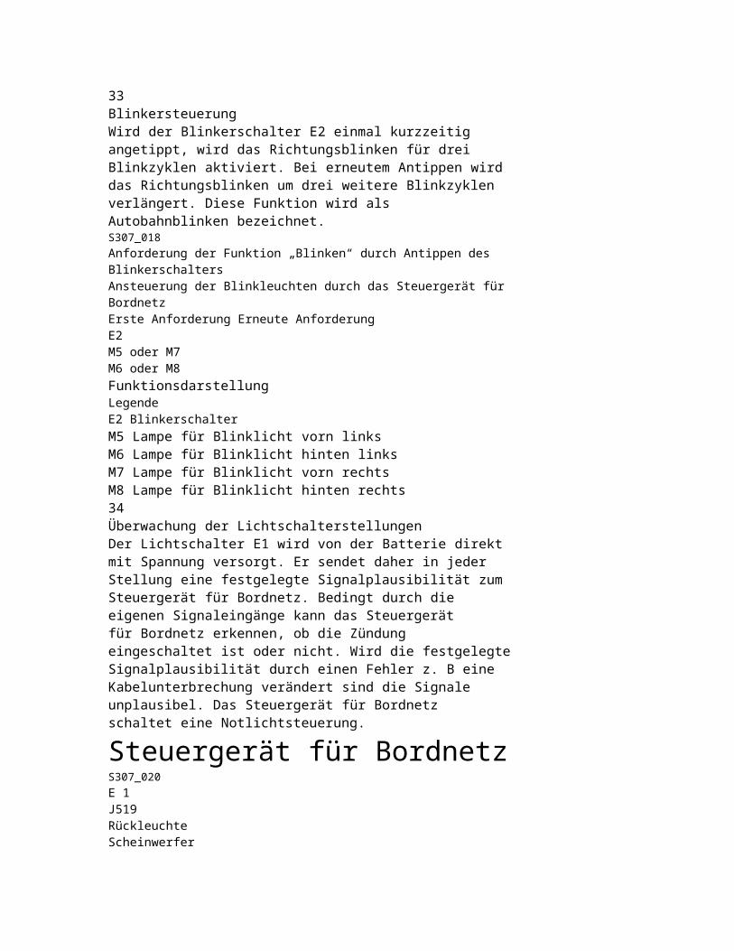
Steuergerät für BordnetzFunktionsplanS307_019LegendeD Zündanlassschalter Klemme 15E1 LichtschalterE4 Schalter für Handabblendung undLichthupeE19 Schalter für ParklichtF BremslichtschalterF4 Schalter für RückfahrleuchtenJ519 Steuergerät für BordnetzJ527 Steuergerät für LenksäulenelektronikM25 Lampe für hochgesetztes BremslichtX KennzeichenleuchteE4E19DF4FKl. 15XJ519J527M25CAN-Datenbus Komfort33Blinkersteuerung
Wird der Blinkerschalter E2 einmal kurzzeitigangetippt, wird das Richtungsblinken für dreiBlinkzyklen aktiviert. Bei erneutem Antippen wirddas Richtungsblinken um drei weitere Blinkzyklenverlängert. Diese Funktion wird alsAutobahnblinken bezeichnet.S307_018Anforderung der Funktion „Blinken“ durch Antippen desBlinkerschaltersAnsteuerung der Blinkleuchten durch das Steuergerät fürBordnetzErste Anforderung Erneute AnforderungE2M5 oder M7M6 oder M8FunktionsdarstellungLegendeE2 BlinkerschalterM5 Lampe für Blinklicht vorn linksM6 Lampe für Blinklicht hinten linksM7 Lampe für Blinklicht vorn rechtsM8 Lampe für Blinklicht hinten rechts34Überwachung der LichtschalterstellungenDer Lichtschalter E1 wird von der Batterie direktmit Spannung versorgt. Er sendet daher in jederStellung eine festgelegte Signalplausibilität zumSteuergerät für Bordnetz. Bedingt durch dieeigenen Signaleingänge kann das Steuergerätfür Bordnetz erkennen, ob die Zündungeingeschaltet ist oder nicht. Wird die festgelegteSignalplausibilität durch einen Fehler z. B eineKabelunterbrechung verändert sind die Signaleunplausibel. Das Steuergerät für Bordnetzschaltet eine Notlichtsteuerung.
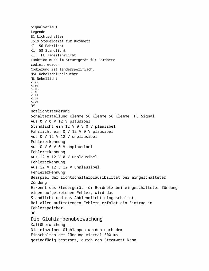
Steuergerät für BordnetzS307_020E 1J519RückleuchteScheinwerferSignalverlaufLegendeE1 LichtschalterJ519 Steuergerät für BordnetzKl. 56 FahrlichtKl. 58 StandlichtKl. TFL TagesfahrlichtFunktion muss im Steuergerät für Bordnetzcodiert werdenCodierung ist länderspezifisch.
NSL NebelschlussleuchteNL NebellichtKl 58Kl 56Kl TFLKl NLKl NSLKl 15Kl 3035NotlichtsteuerungSchalterstellung Klemme 58 Klemme 56 Klemme TFL SignalAus 0 V 0 V 12 V plausibelStandlicht ein 12 V 0 V 0 V plausibelFahrlicht ein 0 V 12 V 0 V plausibelAus 0 V 12 V 12 V unplausibelFehlererkennungAus 0 V 0 V 0 V unplausibelFehlererkennungAus 12 V 12 V 0 V unplausibelFehlererkennungAus 12 V 12 V 12 V unplausibelFehlererkennungBeispiel der Lichtschalterplausibilität bei eingeschalteter ZündungErkennt das Steuergerät für Bordnetz bei eingeschalteter Zündung einen aufgetretenen Fehler, wird dasStandlicht und das Abblendlicht eingeschaltet.Bei allen auftretenden Fehlern erfolgt ein Eintrag im Fehlerspeicher.36Die GlühlampenüberwachungKaltüberwachungDie einzelnen Glühlampen werden nach demEinschalten der Zündung viermal 500 msgeringfügig bestromt, durch den Stromwert kanndas Steuergerät für Bordnetz eine defekteGlühlampe erkennen.WarmüberwachungDie Ansteuerung der einzelnen Glühlampenerfolgt durch Halbleiter-Bausteine, die sich imSteuergerät für Bordnetz befinden. Sie erkennen,ob eine Überlast, ein Kurzschluss, oder eineUnterbrechung vorliegt.FehlererkennungBei beiden Überwachungsarten erfolgt nacherkanntem Fehler ein Eintrag im Fehlerspeichersowie eine Anzeige im Schalttafeleinsatz.Eine erneuerte Glühlampe wird durch dieÜberwachung erkannt, der Fehler gelöscht unddie Anzeige abgeschaltet.
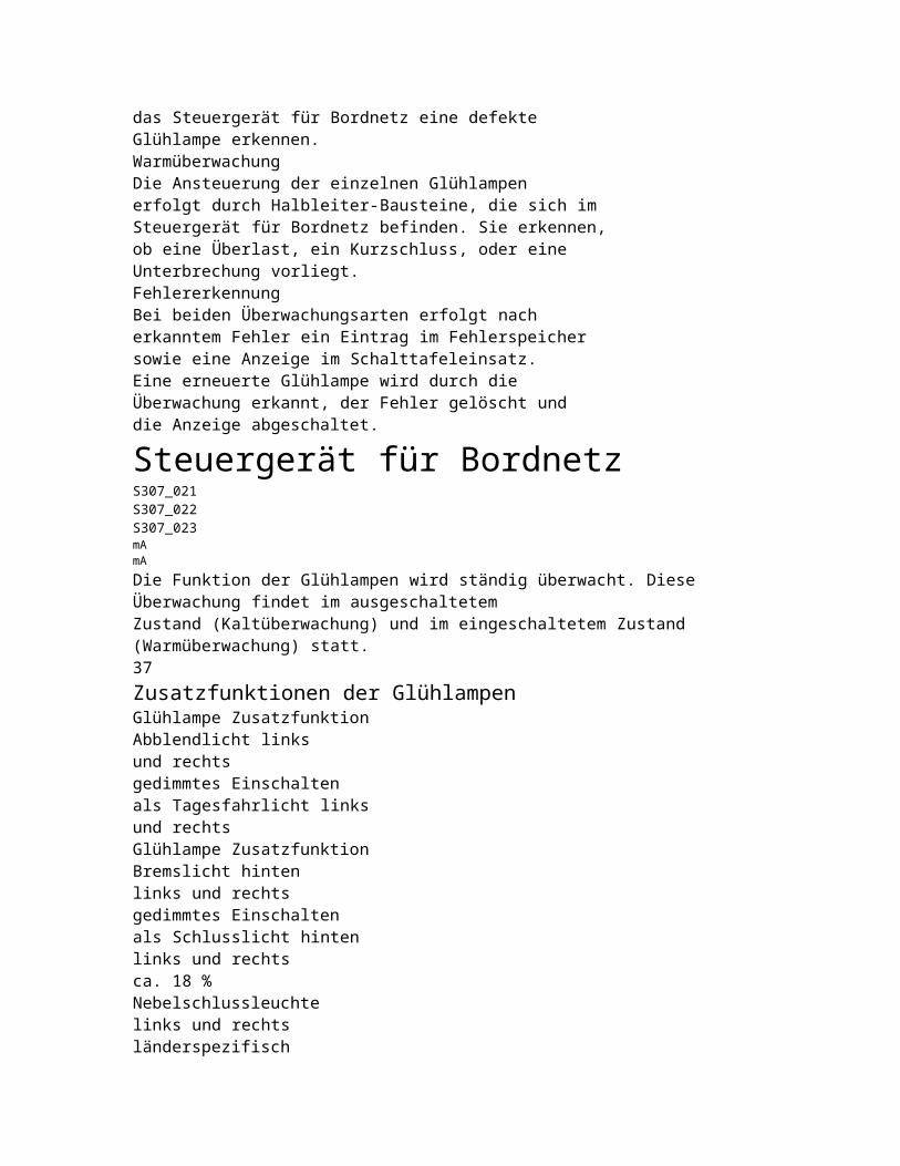
Steuergerät für BordnetzS307_021
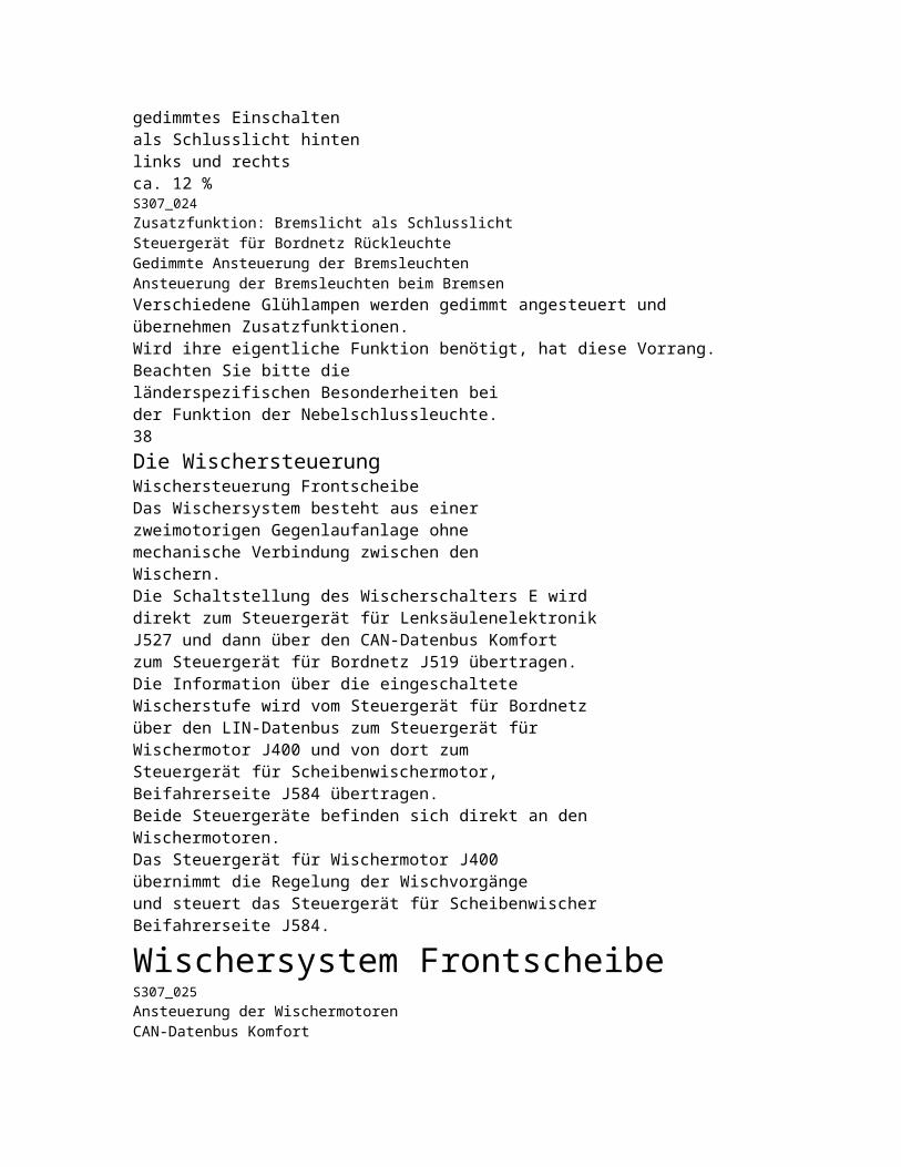
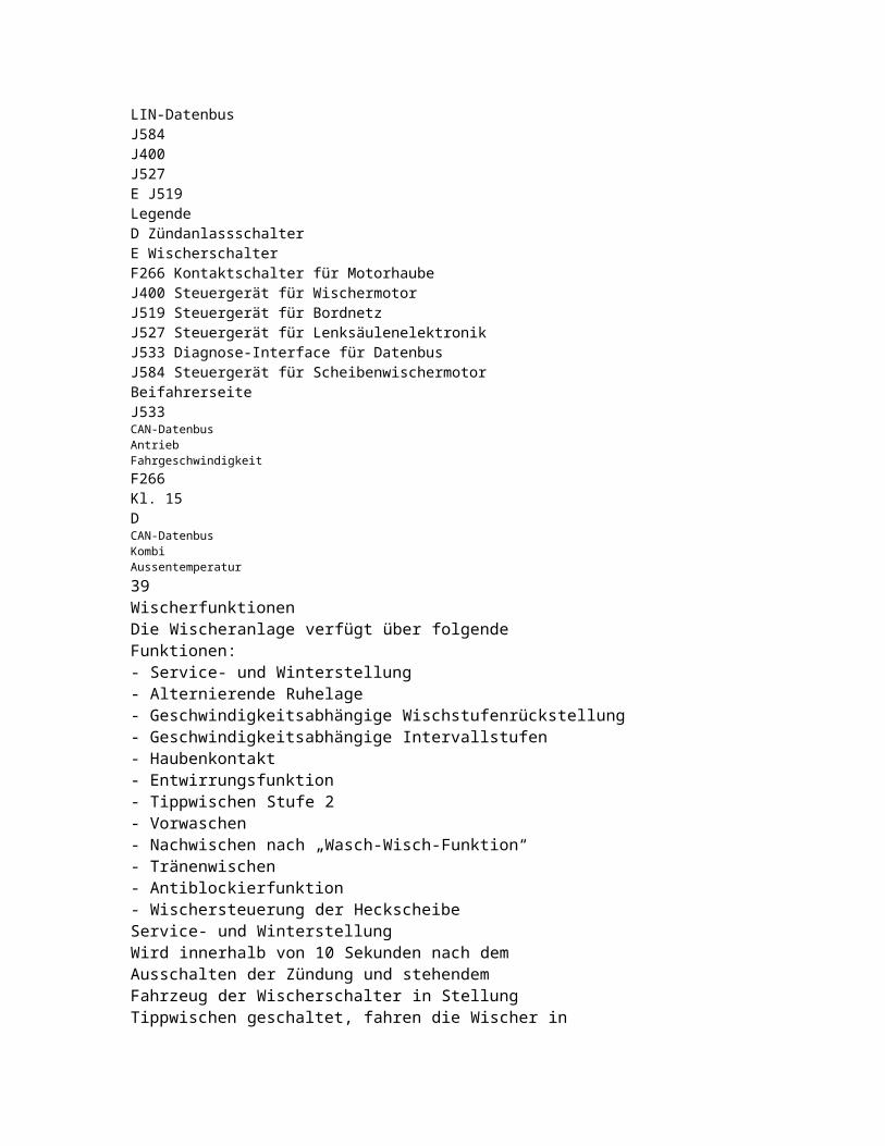
S307_022S307_023mAmADie Funktion der Glühlampen wird ständig überwacht. Diese Überwachung findet im ausgeschaltetemZustand (Kaltüberwachung) und im eingeschaltetem Zustand (Warmüberwachung) statt.37Zusatzfunktionen der GlühlampenGlühlampe ZusatzfunktionAbblendlicht linksund rechtsgedimmtes Einschaltenals Tagesfahrlicht linksund rechtsGlühlampe ZusatzfunktionBremslicht hintenlinks und rechtsgedimmtes Einschaltenals Schlusslicht hintenlinks und rechtsca. 18 %Nebelschlussleuchtelinks und rechtsländerspezifischgedimmtes Einschaltenals Schlusslicht hintenlinks und rechtsca. 12 %S307_024Zusatzfunktion: Bremslicht als SchlusslichtSteuergerät für Bordnetz RückleuchteGedimmte Ansteuerung der BremsleuchtenAnsteuerung der Bremsleuchten beim BremsenVerschiedene Glühlampen werden gedimmt angesteuert und übernehmen Zusatzfunktionen.Wird ihre eigentliche Funktion benötigt, hat diese Vorrang.Beachten Sie bitte dieländerspezifischen Besonderheiten beider Funktion der Nebelschlussleuchte.38Die WischersteuerungWischersteuerung FrontscheibeDas Wischersystem besteht aus einerzweimotorigen Gegenlaufanlage ohnemechanische Verbindung zwischen denWischern.Die Schaltstellung des Wischerschalters E wirddirekt zum Steuergerät für LenksäulenelektronikJ527 und dann über den CAN-Datenbus Komfort
zum Steuergerät für Bordnetz J519 übertragen.Die Information über die eingeschalteteWischerstufe wird vom Steuergerät für Bordnetzüber den LIN-Datenbus zum Steuergerät fürWischermotor J400 und von dort zumSteuergerät für Scheibenwischermotor,Beifahrerseite J584 übertragen.Beide Steuergeräte befinden sich direkt an denWischermotoren.Das Steuergerät für Wischermotor J400übernimmt die Regelung der Wischvorgängeund steuert das Steuergerät für ScheibenwischerBeifahrerseite J584.
Wischersystem FrontscheibeS307_025Ansteuerung der WischermotorenCAN-Datenbus KomfortLIN-DatenbusJ584J400J527E J519LegendeD ZündanlassschalterE WischerschalterF266 Kontaktschalter für MotorhaubeJ400 Steuergerät für WischermotorJ519 Steuergerät für BordnetzJ527 Steuergerät für LenksäulenelektronikJ533 Diagnose-Interface für DatenbusJ584 Steuergerät für ScheibenwischermotorBeifahrerseiteJ533CAN-DatenbusAntriebFahrgeschwindigkeitF266Kl. 15DCAN-DatenbusKombiAussentemperatur39WischerfunktionenDie Wischeranlage verfügt über folgendeFunktionen:- Service- und Winterstellung- Alternierende Ruhelage- Geschwindigkeitsabhängige Wischstufenrückstellung- Geschwindigkeitsabhängige Intervallstufen- Haubenkontakt- Entwirrungsfunktion
- Tippwischen Stufe 2- Vorwaschen- Nachwischen nach „Wasch-Wisch-Funktion“- Tränenwischen- Antiblockierfunktion- Wischersteuerung der HeckscheibeService- und WinterstellungWird innerhalb von 10 Sekunden nach demAusschalten der Zündung und stehendemFahrzeug der Wischerschalter in StellungTippwischen geschaltet, fahren die Wischer indie obere Wendelage.Diese Funktion ist bei geöffneter Motorhaubenicht aktivierbar.S307_026Service- und Winterstellung40Alternierende RuhelageDamit eine bleibende Verformung derWischerblätter verhindert wird, fährt derWischer bei jedem zweiten Ausschalten wiederein Stück aufwärts. Dabei wird die Lage desWischerblattes verändert.Zusätzlich kann nach mehrmaligen Ausschaltender Zündung die Ruhelage nochmals geändertwerden.Geschwindigkeitsabhängige WischstufenrückstellungSinkt die Fahrgeschwindigkeit unter 4 km/h, wirddie gewählte Wischergeschwindigkeit um eineStufe verringert. Beim Erhöhen derGeschwindigkeit über 8 km/h geht dieWischergeschwindigkeit auf die gewählte Stufezurück.Rückschaltungen:Stufe 2 auf Stufe 1- Klemme 15 ein- Wischerschalter auf Stufe 2- Fahrgeschwindigkeit < 4 km/hStufe 1 auf Stufe Intervallbetrieb- Klemme 15 ein- Wischerschalter auf Stufe 1- Fahrgeschwindigkeit < 4 km/h(Intervallpause 4 s)
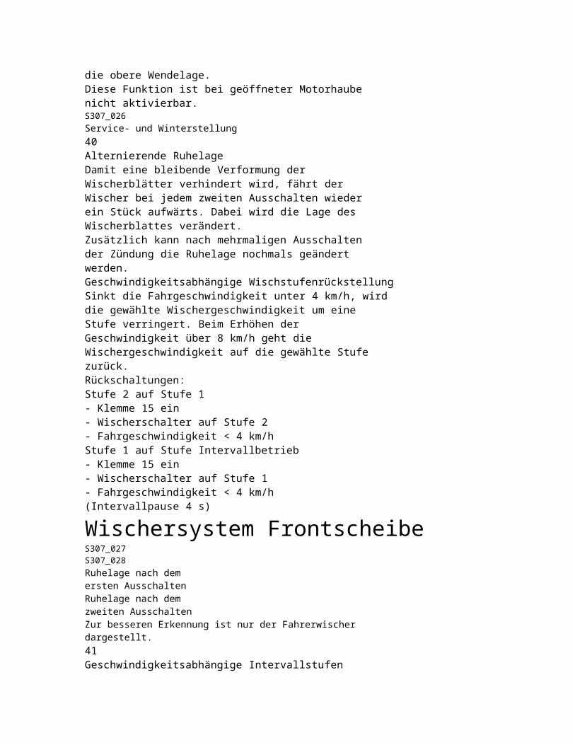
Wischersystem FrontscheibeS307_027S307_028Ruhelage nach demersten AusschaltenRuhelage nach dem
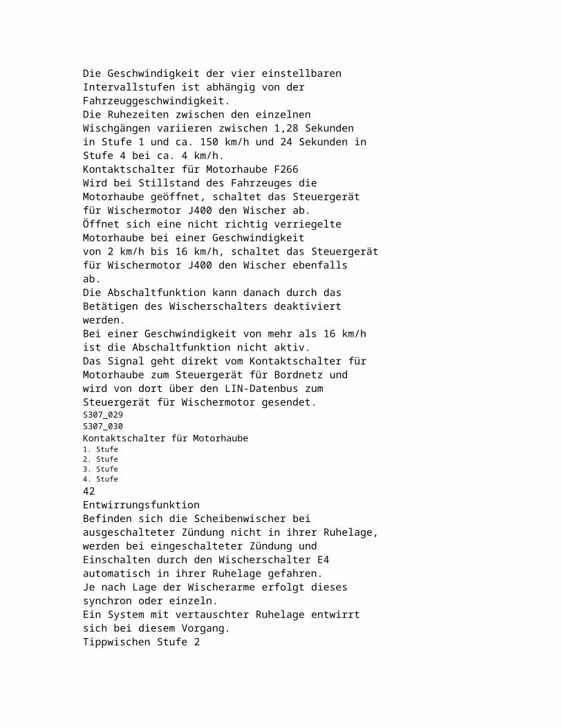
zweiten AusschaltenZur besseren Erkennung ist nur der Fahrerwischerdargestellt.41Geschwindigkeitsabhängige IntervallstufenDie Geschwindigkeit der vier einstellbarenIntervallstufen ist abhängig von derFahrzeuggeschwindigkeit.Die Ruhezeiten zwischen den einzelnenWischgängen variieren zwischen 1,28 Sekundenin Stufe 1 und ca. 150 km/h und 24 Sekunden inStufe 4 bei ca. 4 km/h.Kontaktschalter für Motorhaube F266Wird bei Stillstand des Fahrzeuges dieMotorhaube geöffnet, schaltet das Steuergerätfür Wischermotor J400 den Wischer ab.Öffnet sich eine nicht richtig verriegelteMotorhaube bei einer Geschwindigkeitvon 2 km/h bis 16 km/h, schaltet das Steuergerätfür Wischermotor J400 den Wischer ebenfallsab.Die Abschaltfunktion kann danach durch dasBetätigen des Wischerschalters deaktiviertwerden.Bei einer Geschwindigkeit von mehr als 16 km/hist die Abschaltfunktion nicht aktiv.Das Signal geht direkt vom Kontaktschalter fürMotorhaube zum Steuergerät für Bordnetz undwird von dort über den LIN-Datenbus zumSteuergerät für Wischermotor gesendet.S307_029S307_030Kontaktschalter für Motorhaube1. Stufe2. Stufe3. Stufe4. Stufe42EntwirrungsfunktionBefinden sich die Scheibenwischer beiausgeschalteter Zündung nicht in ihrer Ruhelage,werden bei eingeschalteter Zündung undEinschalten durch den Wischerschalter E4automatisch in ihrer Ruhelage gefahren.Je nach Lage der Wischerarme erfolgt diesessynchron oder einzeln.Ein System mit vertauschter Ruhelage entwirrtsich bei diesem Vorgang.Tippwischen Stufe 2Wird die Funktion „Tippwischen“ länger als zweiSekunden betätigt, schaltet der Wischer in die
zweite Stufe.
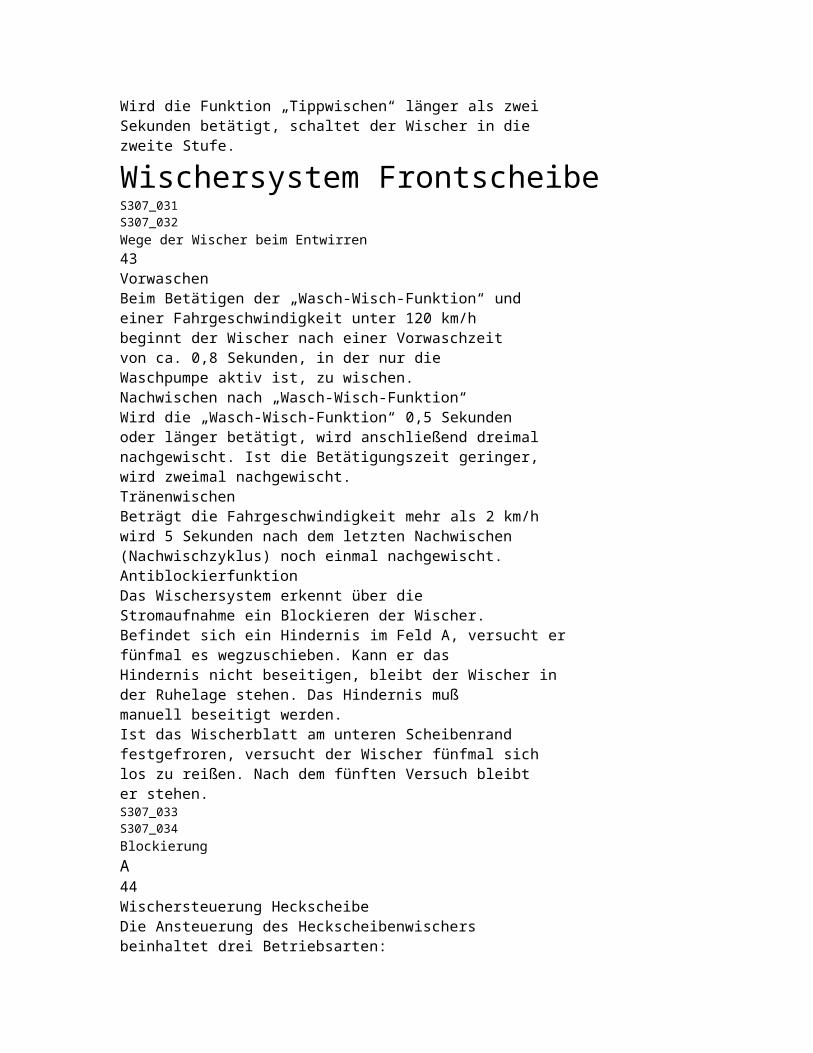
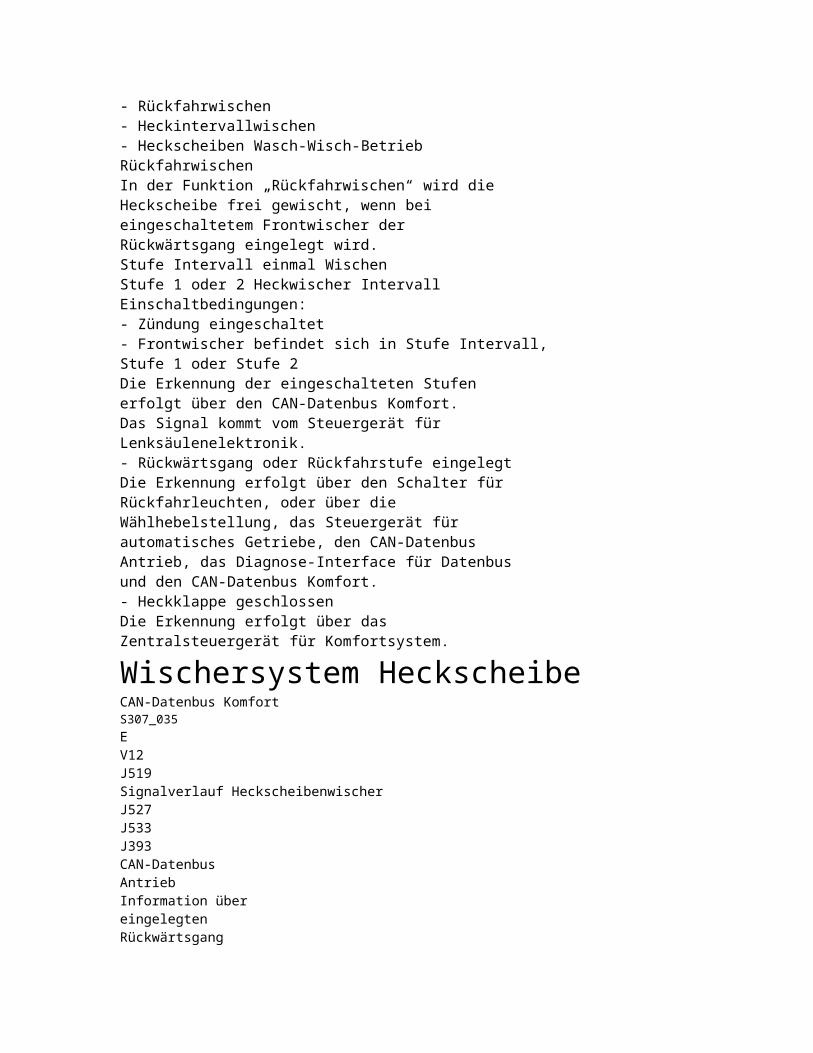
Wischersystem FrontscheibeS307_031S307_032Wege der Wischer beim Entwirren43VorwaschenBeim Betätigen der „Wasch-Wisch-Funktion“ undeiner Fahrgeschwindigkeit unter 120 km/hbeginnt der Wischer nach einer Vorwaschzeitvon ca. 0,8 Sekunden, in der nur dieWaschpumpe aktiv ist, zu wischen.Nachwischen nach „Wasch-Wisch-Funktion“Wird die „Wasch-Wisch-Funktion“ 0,5 Sekundenoder länger betätigt, wird anschließend dreimalnachgewischt. Ist die Betätigungszeit geringer,wird zweimal nachgewischt.TränenwischenBeträgt die Fahrgeschwindigkeit mehr als 2 km/hwird 5 Sekunden nach dem letzten Nachwischen(Nachwischzyklus) noch einmal nachgewischt.AntiblockierfunktionDas Wischersystem erkennt über dieStromaufnahme ein Blockieren der Wischer.Befindet sich ein Hindernis im Feld A, versucht erfünfmal es wegzuschieben. Kann er dasHindernis nicht beseitigen, bleibt der Wischer inder Ruhelage stehen. Das Hindernis mußmanuell beseitigt werden.Ist das Wischerblatt am unteren Scheibenrandfestgefroren, versucht der Wischer fünfmal sichlos zu reißen. Nach dem fünften Versuch bleibter stehen.S307_033S307_034BlockierungA44Wischersteuerung HeckscheibeDie Ansteuerung des Heckscheibenwischersbeinhaltet drei Betriebsarten:- Rückfahrwischen- Heckintervallwischen- Heckscheiben Wasch-Wisch-BetriebRückfahrwischenIn der Funktion „Rückfahrwischen“ wird dieHeckscheibe frei gewischt, wenn beieingeschaltetem Frontwischer derRückwärtsgang eingelegt wird.
Stufe Intervall einmal WischenStufe 1 oder 2 Heckwischer IntervallEinschaltbedingungen:- Zündung eingeschaltet- Frontwischer befindet sich in Stufe Intervall,Stufe 1 oder Stufe 2Die Erkennung der eingeschalteten Stufenerfolgt über den CAN-Datenbus Komfort.Das Signal kommt vom Steuergerät fürLenksäulenelektronik.- Rückwärtsgang oder Rückfahrstufe eingelegtDie Erkennung erfolgt über den Schalter fürRückfahrleuchten, oder über dieWählhebelstellung, das Steuergerät fürautomatisches Getriebe, den CAN-DatenbusAntrieb, das Diagnose-Interface für Datenbusund den CAN-Datenbus Komfort.- Heckklappe geschlossenDie Erkennung erfolgt über dasZentralsteuergerät für Komfortsystem.
Wischersystem HeckscheibeCAN-Datenbus KomfortS307_035EV12J519Signalverlauf HeckscheibenwischerJ527J533J393CAN-DatenbusAntriebInformation übereingelegtenRückwärtsgangLegendeD ZündanlassschalterE WischerschalterJ393 Zentralsteuergerät für KomfortsystemJ519 Steuergerät für BordnetzJ527 Steuergerät für LenksäulenelektronikJ533 Diagnose-Interface für DatenbusV12 Motor für HeckscheibenwischerDKl. 1545HeckintervallwischenBei eingeschalteter Wischerstufe„Heckintervallwischen“ wird die Heckscheibe inIntervallen frei gewischt.Einschaltbedingungen:
- Zündung eingeschaltet- Stufe „Heckintervallwischen“ ein:Die Erkennung erfolgt über den Wischerschalter,das Steuergerät für Lenksäulenelektronikund den CAN-Datenbus Komfort.- Heckklappe geschlossen:Die Erkennung erfolgt über dasZentralsteuergerät für Komfortsystem.Heckscheiben Wasch-Wisch-BetriebIn der Stufe „Heckscheiben Wasch-Wisch-Betrieb“ fördert die DualwaschpumpeScheiben-Waschwasser auf die Heckscheibe unddie Heckscheibe wird freigewischt.Einschaltbedingungen:- Zündung eingeschaltet- Stufe „Heckscheiben Wasch-Wisch-Betrieb“ein:Die Erkennung erfolgt über denWischerschalter, das Steuergerät fürLenksäulenelektronik und den CAN-DatenbusKomfort.- Heckklappe geschlossen:Die Erkennung erfolgt über dasZentralsteuergerät für Komfortsystem.S307_036S307_03746Kontrollleuchten und AnzeigenDas Steuergerät mit Anzeigeeinheit imSchalttafeleinsatz steuert das Display, dieanalogen Anzeigeinstrumente und dieKontrollleuchten an.Die Kühlmitteltemperaturanzeige steht beiFahrzeugen mit Kennfeldkühlung beiKühlmitteltemperaturen zwischen 75 °Cund 107 °C konstant auf 90 °C, bei Fahrzeugenohne Kennfeldkühlung beiKühlmitteltemperaturen zwischen 75 °Cund 115 °C konstant auf 90 °C.Dadurch wird eine sich ständig änderndeAnzeige verhindert.
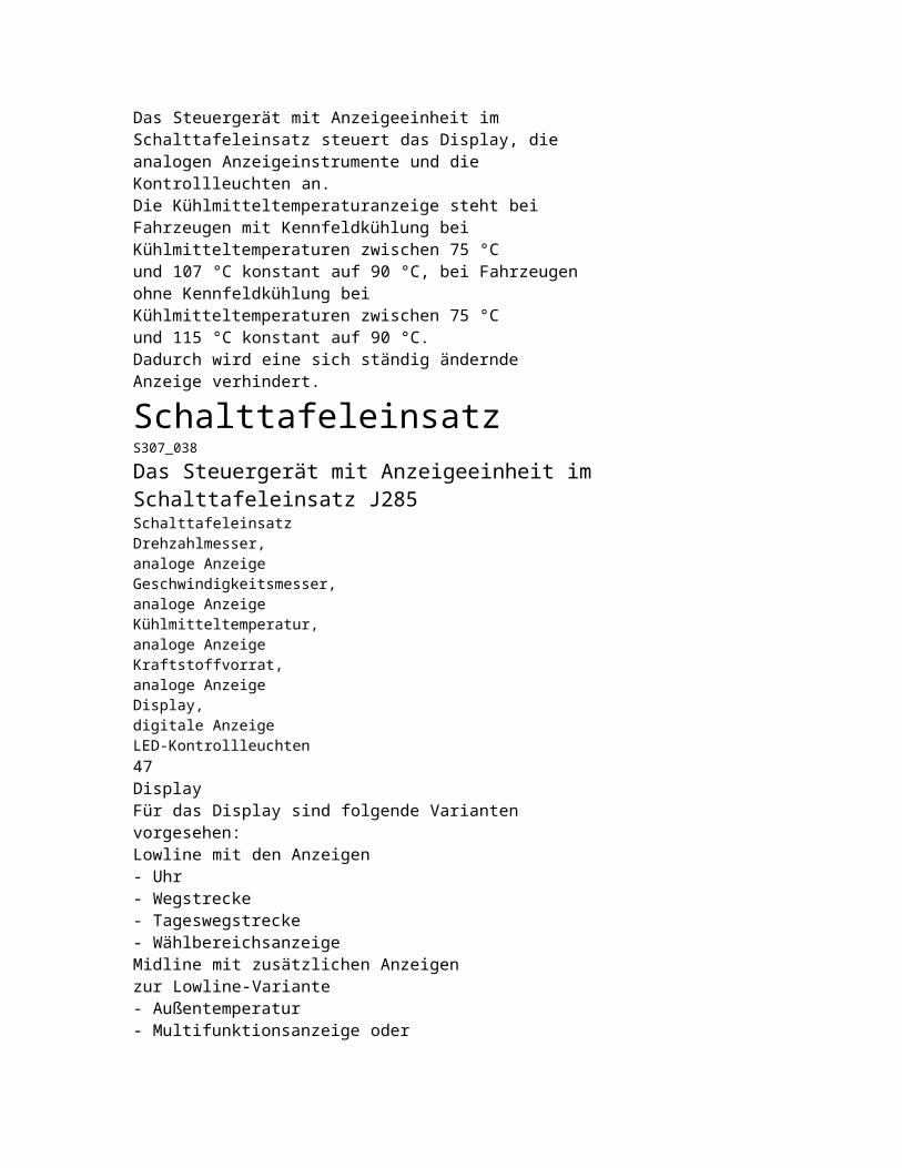
SchalttafeleinsatzS307_038Das Steuergerät mit Anzeigeeinheit im Schalttafeleinsatz J285SchalttafeleinsatzDrehzahlmesser,analoge AnzeigeGeschwindigkeitsmesser,
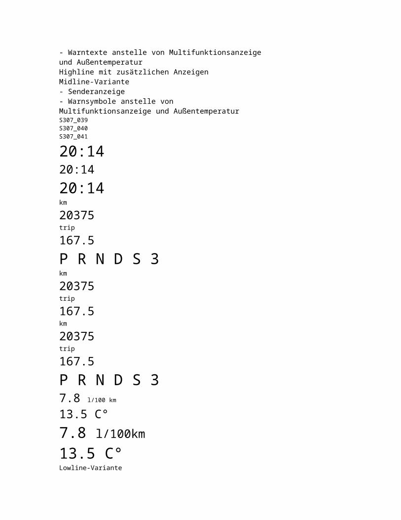
analoge AnzeigeKühlmitteltemperatur,analoge AnzeigeKraftstoffvorrat,analoge AnzeigeDisplay,digitale AnzeigeLED-Kontrollleuchten47DisplayFür das Display sind folgende Variantenvorgesehen:Lowline mit den Anzeigen- Uhr- Wegstrecke- Tageswegstrecke- WählbereichsanzeigeMidline mit zusätzlichen Anzeigenzur Lowline-Variante- Außentemperatur- Multifunktionsanzeige oder- Warntexte anstelle von Multifunktionsanzeigeund AußentemperaturHighline mit zusätzlichen AnzeigenMidline-Variante- Senderanzeige- Warnsymbole anstelle vonMultifunktionsanzeige und AußentemperaturS307_039S307_040S307_041
20:1420:1420:14km20375trip167.5P R N D S 3km20375trip167.5km
20375trip167.5P R N D S 37.8 l/100 km
13.5 C°7.8 l/100km13.5 C°Lowline-VarianteMidline-VarianteHighline-Variante
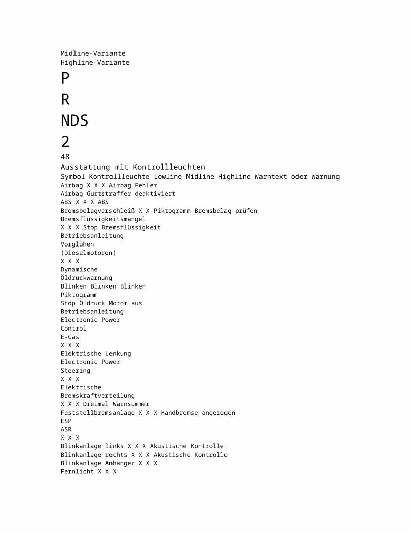
PRNDS248Ausstattung mit KontrollleuchtenSymbol Kontrollleuchte Lowline Midline Highline Warntext oder WarnungAirbag X X X Airbag FehlerAirbag Gurtstraffer deaktiviertABS X X X ABSBremsbelagverschleiß X X Piktogramm Bremsbelag prüfenBremsflüssigkeitsmangelX X X Stop BremsflüssigkeitBetriebsanleitungVorglühen(Dieselmotoren)X X XDynamischeÖldruckwarnungBlinken Blinken BlinkenPiktogrammStop Öldruck Motor ausBetriebsanleitungElectronic PowerControlE-GasX X XElektrische LenkungElectronic PowerSteeringX X XElektrischeBremskraftverteilungX X X Dreimal Warnsummer
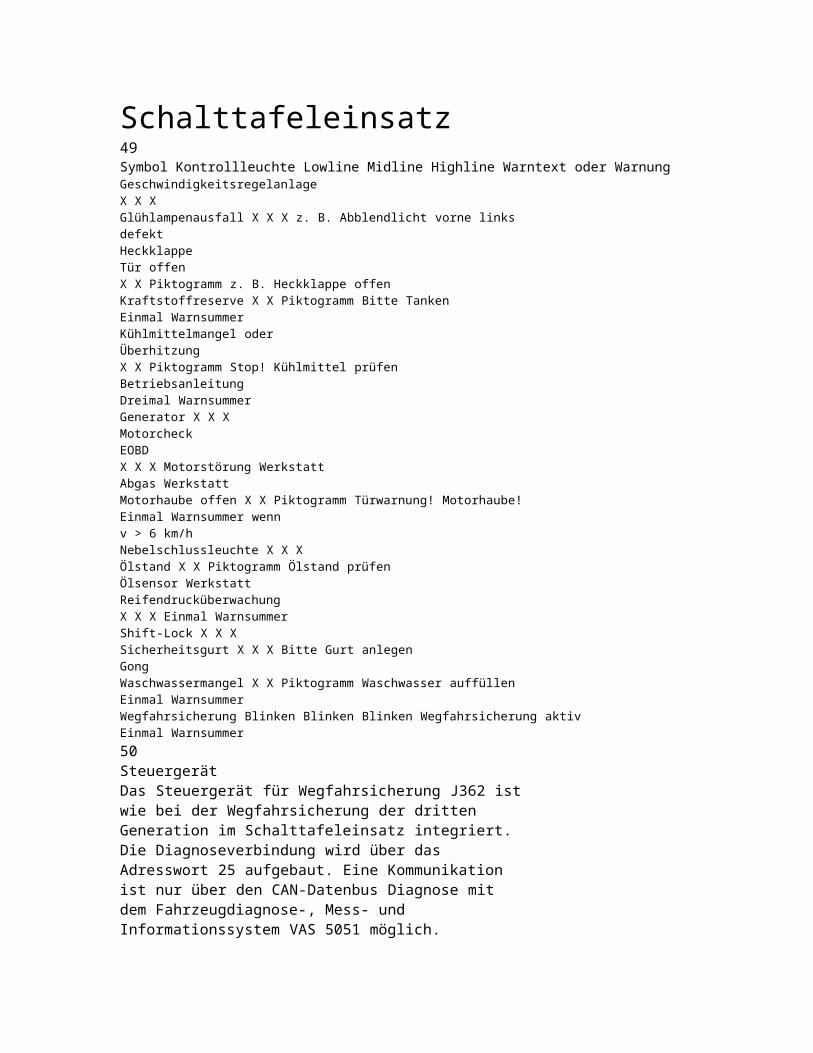
Feststellbremsanlage X X X Handbremse angezogenESPASRX X XBlinkanlage links X X X Akustische KontrolleBlinkanlage rechts X X X Akustische KontrolleBlinkanlage Anhänger X X XFernlicht X X X
Schalttafeleinsatz49Symbol Kontrollleuchte Lowline Midline Highline Warntext oder WarnungGeschwindigkeitsregelanlageX X XGlühlampenausfall X X X z. B. Abblendlicht vorne linksdefektHeckklappeTür offenX X Piktogramm z. B. Heckklappe offenKraftstoffreserve X X Piktogramm Bitte TankenEinmal WarnsummerKühlmittelmangel oderÜberhitzungX X Piktogramm Stop! Kühlmittel prüfenBetriebsanleitungDreimal WarnsummerGenerator X X XMotorcheckEOBDX X X Motorstörung WerkstattAbgas WerkstattMotorhaube offen X X Piktogramm Türwarnung! Motorhaube!Einmal Warnsummer wennv > 6 km/hNebelschlussleuchte X X XÖlstand X X Piktogramm Ölstand prüfenÖlsensor WerkstattReifendrucküberwachungX X X Einmal WarnsummerShift-Lock X X XSicherheitsgurt X X X Bitte Gurt anlegenGongWaschwassermangel X X Piktogramm Waschwasser auffüllenEinmal WarnsummerWegfahrsicherung Blinken Blinken Blinken Wegfahrsicherung aktivEinmal Warnsummer50SteuergerätDas Steuergerät für Wegfahrsicherung J362 istwie bei der Wegfahrsicherung der drittenGeneration im Schalttafeleinsatz integriert.Die Diagnoseverbindung wird über dasAdresswort 25 aufgebaut. Eine Kommunikationist nur über den CAN-Datenbus Diagnose mitdem Fahrzeugdiagnose-, Mess- undInformationssystem VAS 5051 möglich.
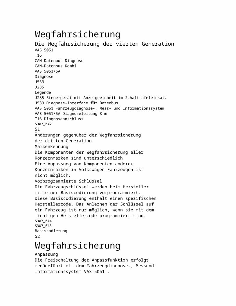
WegfahrsicherungDie Wegfahrsicherung der vierten GenerationVAS 5051T16CAN-Datenbus DiagnoseCAN-Datenbus KombiVAS 5051/5ADiagnoseJ533J285LegendeJ285 Steuergerät mit Anzeigeeinheit im SchalttafeleinsatzJ533 Diagnose-Interface für DatenbusVAS 5051 Fahrzeugdiagnose-, Mess- und InformationssystemVAS 5051/5A Diagnoseleitung 3 mT16 DiagnoseanschlussS307_04251Änderungen gegenüber der Wegfahrsicherungder dritten GenerationMarkenkennungDie Komponenten der Wegfahrsicherung allerKonzernmarken sind unterschiedlich.Eine Anpassung von Komponenten andererKonzernmarken in Volkswagen-Fahrzeugen istnicht möglich.Vorprogrammierte SchlüsselDie Fahrzeugschlüssel werden beim Herstellermit einer Basiscodierung vorprogrammiert.Diese Basiscodierung enthält einen spezifischenHerstellercode. Das Anlernen der Schlüssel aufein Fahrzeug ist nur möglich, wenn sie mit demrichtigen Herstellercode programmiert sind.S307_044S307_043Basiscodierung52
WegfahrsicherungAnpassungDie Freischaltung der Anpassfunktion erfolgtmenügeführt mit dem Fahrzeugdiagnose-, MessundInformationssystem VAS 5051 .Die Persönliche-Identifikations-Nummer (PIN)zur Anpassung kann zur Zeit über den Händler-Online-Zugriff (HOLZ) angefordert werden.Zu einem späteren Zeitpunkt wird die Anpassungüber eine Online-Verbindung durchgeführt.Austausch des MotorsteuergerätesDas Motorsteuergerät wird, wie bei der
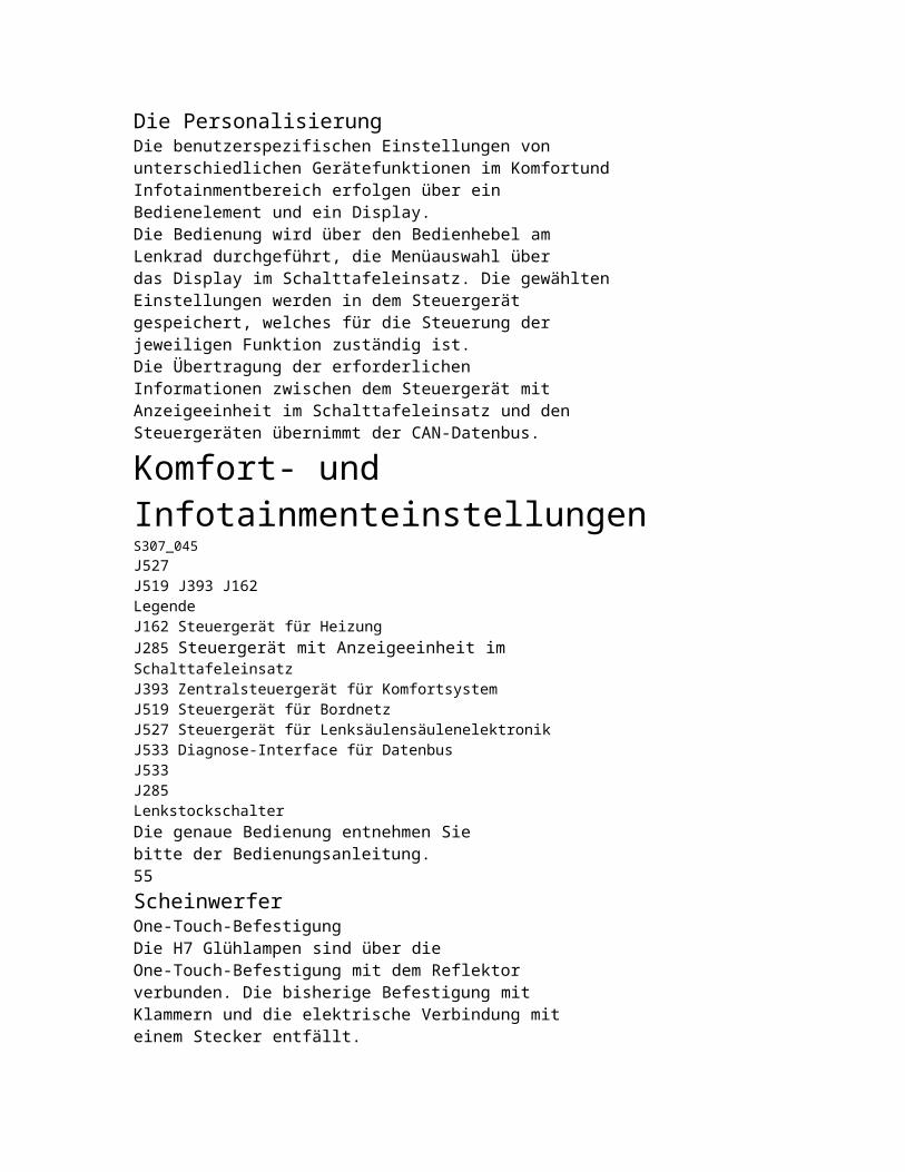
Wegfahrsicherung der dritten Generation,freigeschaltet. Es müssen zwei der dreiangelernten Komponenten(Schlüssel und Schalttafeleinsatz) im Fahrzeugverbleiben.Bei der Anpassung eines neuen Steuergeräteskann dieses ohnePersönliche-Identifikations-Nummer erfolgen.Zur Anpassung eines Steuergerätes, dass bereitsin einem anderen Fahrzeug eingebaut war, istdie Persönliche-Identifikations-Nummererforderlich.53Austausch des SchalttafeleinsatzesDie Anpassung ist wie bei der Wegfahrsicherungder dritten Generation durchzuführen.Es müssen ebenfalls zwei der drei angelerntenKomponenten (Schlüssel und Motorsteuergerät)im Fahrzeug verbleiben.Die Anpassung eines neuen Schalttafeleinsatzeskann ohne Persönliche-Identifikations-Nummererfolgen.Bei einem bereits genutzten Schalttafeleinsatzwird, wie beim Motorsteuergerät, diePersönliche-Identifikations-Nummer benötigt.Nach dem Wechseln erkennt das Steuergerät fürWegfahrsicherung J362 unbekannte Schlüssel.Auf Grund dessen beginnt eine Sperrzeit vonfünf Minuten zu laufen, in denen der Motor nichtgestartet werden kann.Bei einem Tausch von mehr als einerKomponete müssen alle dreiKomponeten erneuert werden, daweniger als zwei der angelerntenKomponeten im Fahrzeug verbleiben.54Die PersonalisierungDie benutzerspezifischen Einstellungen vonunterschiedlichen Gerätefunktionen im KomfortundInfotainmentbereich erfolgen über einBedienelement und ein Display.Die Bedienung wird über den Bedienhebel amLenkrad durchgeführt, die Menüauswahl überdas Display im Schalttafeleinsatz. Die gewähltenEinstellungen werden in dem Steuergerätgespeichert, welches für die Steuerung derjeweiligen Funktion zuständig ist.Die Übertragung der erforderlichenInformationen zwischen dem Steuergerät mit
Anzeigeeinheit im Schalttafeleinsatz und denSteuergeräten übernimmt der CAN-Datenbus.
Komfort- und InfotainmenteinstellungenS307_045J527J519 J393 J162LegendeJ162 Steuergerät für HeizungJ285 Steuergerät mit Anzeigeeinheit imSchalttafeleinsatzJ393 Zentralsteuergerät für KomfortsystemJ519 Steuergerät für BordnetzJ527 Steuergerät für LenksäulensäulenelektronikJ533 Diagnose-Interface für DatenbusJ533J285LenkstockschalterDie genaue Bedienung entnehmen Siebitte der Bedienungsanleitung.55ScheinwerferOne-Touch-BefestigungDie H7 Glühlampen sind über dieOne-Touch-Befestigung mit dem Reflektorverbunden. Die bisherige Befestigung mitKlammern und die elektrische Verbindung miteinem Stecker entfällt.Durch One-Touch können die Befestigungen derGlühlampen mit einer Drehbewegung gelöstwerden.Anschließend wird die Glühlampe aus derBefestigung gezogen.
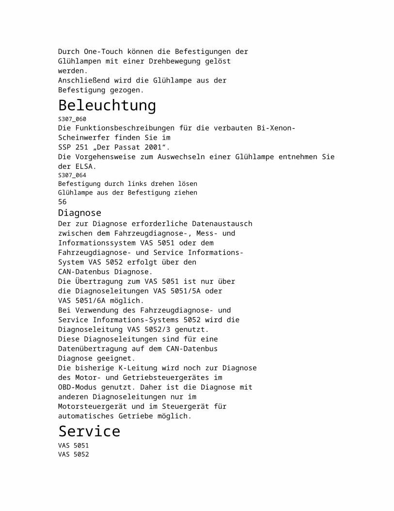
BeleuchtungS307_060Die Funktionsbeschreibungen für die verbauten Bi-Xenon-Scheinwerfer finden Sie imSSP 251 „Der Passat 2001“.Die Vorgehensweise zum Auswechseln einer Glühlampe entnehmen Sie der ELSA.S307_064Befestigung durch links drehen lösenGlühlampe aus der Befestigung ziehen56DiagnoseDer zur Diagnose erforderliche Datenaustauschzwischen dem Fahrzeugdiagnose-, Mess- undInformationssystem VAS 5051 oder dem
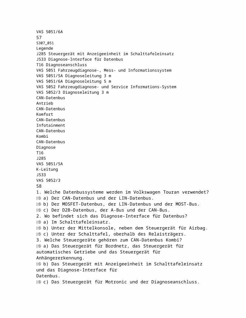
Fahrzeugdiagnose- und Service Informations-System VAS 5052 erfolgt über denCAN-Datenbus Diagnose.Die Übertragung zum VAS 5051 ist nur überdie Diagnoseleitungen VAS 5051/5A oderVAS 5051/6A möglich.Bei Verwendung des Fahrzeugdiagnose- undService Informations-Systems 5052 wird dieDiagnoseleitung VAS 5052/3 genutzt.Diese Diagnoseleitungen sind für eineDatenübertragung auf dem CAN-DatenbusDiagnose geeignet.Die bisherige K-Leitung wird noch zur Diagnosedes Motor- und Getriebsteuergerätes imOBD-Modus genutzt. Daher ist die Diagnose mitanderen Diagnoseleitungen nur imMotorsteuergerät und im Steuergerät fürautomatisches Getriebe möglich.
ServiceVAS 5051VAS 5052VAS 5051/6A57S307_051LegendeJ285 Steuergerät mit Anzeigeeinheit im SchalttafeleinsatzJ533 Diagnose-Interface für DatenbusT16 DiagnoseanschlussVAS 5051 Fahrzeugdiagnose-, Mess- und InformationssystemVAS 5051/5A Diagnoseleitung 3 mVAS 5051/6A Diagnoseleitung 5 mVAS 5052 Fahrzeugdiagnose- und Service Informations-SystemVAS 5052/3 Diagnoseleitung 3 mCAN-DatenbusAntriebCAN-DatenbusKomfortCAN-DatenbusInfotainmentCAN-DatenbusKombiCAN-DatenbusDiagnoseT16J285VAS 5051/5AK-LeitungJ533VAS 5052/3581. Welche Datenbussysteme werden im Volkswagen Touran verwendet?
a) Der CAN-Datenbus und der LIN-Datenbus.b) Der MOSFET-Datenbus, der LIN-Datenbus und der MOST-Bus.c) Der D2B-Datenbus, der A-Bus und der CAN-Bus.2. Wo befindet sich das Diagnose-Interface für Datenbus?a) Im Schalttafeleinsatz.b) Unter der Mittelkonsole, neben dem Steuergerät für Airbag.c) Unter der Schalttafel, oberhalb des Relaisträgers.3. Welche Steuergeräte gehören zum CAN-Datenbus Kombi?a) Das Steuergerät für Bordnetz, das Steuergerät für automatisches Getriebe und das Steuergerät fürAnhängererkennung.b) Das Steuergerät mit Anzeigeeinheit im Schalttafeleinsatz und das Diagnose-Interface fürDatenbus.c) Das Steuergerät für Motronic und der Diagnoseanschluss.4. Der LIN-Datenbus überträgt die Daten mit einer Geschwindigkeit vona) 1 kbit/s bis 20 kbit/s.b) 100 kbit/s bis 500 kbit/s.c) 21 Mbit/s.
Prüfen Sie Ihr Wissen595. Welche Funktionen werden vom Steuergerät für Bordnetz gesteuert?a) Die Blinkersteuerung, die beheizbare Heckscheibe, der Kraftstoffpumpenvorlauf.b) Der Wischer für die Front- und Heckscheibe, die Zentralverriegelung, die Instrumentenbeleuchtung.c) Das Lastmanagement, die Generatorvorerregung, die Anlass-Sperre.6. Worin besteht die Hauptaufgabe des Lastmanagements?a) Dafür zu sorgen, dass immer genügend elektrische Energie zum Starten zur Verfügung steht.b) Als elektronische Beladungserkennung warnt sie den Fahrer, wenn das Fahrzeug überladen ist.c) Sie verhindert das der Motor durch unsachgemäße Bedienung überlastet wird.7. Worauf ist bei der Diagnose mit dem Fahrzeug-, Mess- und Informationssystem VAS 5051 amTouran zu achten?a) Zur Diagnose dürfen nur die Diagnoseleitungen VAS 5051/5A und VAS 5051/6A verwendet werden.b) Die Diagnose kann in allen Bereichen mit dem V.A.G 1551 oder V.A.G 1552 durchgeführt werden.c) Die Diagnose ist nur mit dem VAS 9119 möglich.Lösungen:1. a 2. c 3. b 4. a 5. a, c 6. a 7. aNur für den internen Gebrauch © VOLKSWAGEN AG, WolfsburgAlle Rechte sowie technische Änderungen vorbehalten000.2811.27.00 Technischer Stand 02/03
The Touran electrical system construction and function self study program 307 service. the construction and function of new developments represents AGAIN 2 to attention reference the self study program! Contents are not updated. Current ones
examine -, adjusting and instructions for repair take you please from the KD literature planned for it! So far only the cross-linking technology inserted use upper class vehicles is used now also in compact Van's like the Volkswagen Touran. The controllers used for it take over tasks, which were implemented so far by relays and switches. So that they can fulfill these tasks efficiently, they must among themselves exchange large quantities of information (data). Such a data exchange became with the employment of conventional procedures, e.g. the use of line connections, only by the employment of very many cables possible. So that the line connections are limited to a visible number, sets Volkswagen strengthens data bus connections in. This self study program is to help you to learn to know the cross-linking concept in the Volkswagen Touran better. It treats the dispatching of the controllers to the different data bus systems, the locations of the relay places, the safety devices and the controllers. In addition it describes different functions as well as changes in the diagnosis. S307_050 3 on a view introduction. . . . . . . . . . . . . . . . . . . . . . . . . . . . . . . . . . . . . . . 4 LIN data bus. . . . . . . . . . . . . . . . . . . . . . . . . . . . . . . . . . . 16 electrical system. . . . . . . . . . . . . . . . . . . . . . . . . . . . . . . . . . . . . . . 20 diagnostic interfaces for data bus. . . . . . . . . . . . . . . . . . . 24 controller for electrical system. . . . . . . . . . . . . . . . . . . . . . . . . . 28 wiper system windshield. . . . . . . . . . . . . . . . . . . . . . . 38 wiper system back window. . . . . . . . . . . . . . . . . . . . . . . 44 instrument panel employment. . . . . . . . . . . . . . . . . . . . . . . . . . . . . . . . 46 going away safety device. . . . . . . . . . . . . . . . . . . . . . . . . . . . . . . 50 comfort and Infotainmenteinstellungen. . . . . . . . . . . . . 54 lighting. . . . . . . . . . . . . . . . . . . . . . . . . . . . . . . . . . . . . 55 service. . . . . . . . . . . . . . . . . . . . . . . . . . . . . . . . . . . . . . . . . 56 examining it your knowledge. . . . . . . . . . . . . . . . . . . . . . . . . . . . . 58 4 introduction of locations the electrical system of the Touran is decentralized developed. For this reason the safeguard boxes and the relay places at different places are in the vehicle. The accompanying representation shows the different locations. The safeguard boxes and relay places in the electrical system Vorsicherungsbox in the engine compartment on the left of electrical connection box in the engine compartment on the left of 5 safeguard box under the instrument panel on the left of S307_001 relay support at the controller for electrical system, under the instrument panel on the left of relay supports under the instrument panel on the left of 6 the cross-linking concept overview of the interlaced controllers thereby a data exchange between the controllers, is networked it is possible over different data bus systems. The diagnostic interface for data bus J533 (gateway) forms the interface for the data buses: - CAN data bus Infotainment - CAN data bus combination - CAN data bus diagnosis introduction S307_049 LIN data bus CAN data bus drive CAN data bus comfort CAN data bus Infotainment CAN Datenbusleitung k-line LIN Datenbusleitung CAN data bus combination CAN data bus diagnosis in addition to the CAN data bus some electrical components are interlaced CAN data bus drive - CAN data bus comfort - over the LIN data bus. Data minutes changed. Thus the controllers are not by controllers from other motor vehicle types z. B. Touareg or phaeton replaceable. J503 R J412 J525 J162 R78 J533 T16 J220 J519 J345 J255 J136 J285 J431 J388 J604 CAN data bus sensor 7 legend E221 service module in the steering wheel G85 giver for guidance angle G273 sensor for interior monitoring G384 giver for vehicle inclination G419 ESP Sensoreinheit H8 horn for theft alarm system J104 controller for ABS with EDS J136 controller for seat adjustment J162 controller for heating J217 controller for autom. Transmission J220 controller for Motronic J234 controller for Airbag J255 controller for Climatronic J285 controller with display unit in the instrument panel employment J345 controller for trailer recognition J386 door expensive equipment, driver's side J387 door expensive equipment, front seat passenger side J388 door expensive equipment, at the rear
left J389 door expensive equipment, in the back on the right of J393 central controller for comfort system J400 controller for wiper engine J412 controller for control electronics, Handy J431 controller for shining width regulation J446 controller for a park assistance J500 controller for guidance assistance J503 controller with display unit for radio and navigation J519 controller for electrical system J525 controller for digital sound package J527 controller for steering column electronics J533 diagnostic interface for DATE bus J584 controller for windshield wiper motor front seat passenger side J587 controller for selector lever sensor technology J604 controller for air additional heating system R radio R78 TV tV-Tuner T16 diagnostic feature J217 J104 J234 G85 J446 G419 J527 J386 J393 J387 J389 G273 H8 G384 E221 J500 J587 J400 J584 S307_002 of 8 controllers and locations the accompanying diagram contains the controllers, which belong to the CAN data bus drive, as well as their locations. The data are transmitted with a speed of 500 kbit/s. The transmission is made by the orange/black CAN High line and the orange/brown CAN Low line. To the safety device of the data communication the CAN lines are twisted with one another. Introduction the controllers in the CAN data bus drive controller for Motronic J220 under the water box cover controller for ABS with EDS J104 under the floor panel, in the engine compartment controller for Airbag J234 under the center console 9 S307_003 controller for shining width regulation J431 under the instrument panel left, at the tunnel doing TZE diagnostic interface for data bus J533 under the instrument panel, above the relay support controller for automatic transmission J217 in the wheel housing of 10 controllers and locations in the diagram are shown the controllers CAN data bus comfort and their locations. The channel transfer rate amounts to 100 kbit/s. The data are transmitted over the orange/green CAN High line and the orange/brown CAN Low line. Both CAN lines are twisted with one another. Introduction controller for Climatronic J255 in the center console central controller for comfort system J393 under the instrument panel right, sews center console controller for steering column electronics J527 at the guidance stick switch the controllers in the CAN data bus comfort 11 S307_004 diagnostic interface for data bus J533 under the instrument panel, above the relay support controller for electrical system J519 under the instrument panel, at the relay support of door expensive devices J386, J387, J388, J389 in the doors controller for trailer recognition J345 in the side part at the rear left controller for a park assistance J446 in the side part in the back on the right of 12 controllers and locations the controllers CAN data bus and the locations shows the accompanying diagram. The CAN data bus Infotainment transmits the data with a speed of 100 kbit/s. The CAN High line is orange/brown orange/lila and the CAN Low line. Both CAN lines are twisted with one another. Introduction the controllers in the CAN data bus Infotainment controller for control electronics, Handy J412 in the floor space on the right of controller for heating J162 in front right under the fender 13 S307_005 controller with display unit for radio and navigation J503 or radio R in the center console 14 CAN data bus combination the data bus transmits the data in front from the instrument panel employment to the diagnostic interface for data bus. The controller with display unit in the instrument panel employment and the diagnostic interface for data bus are the two only controllers at this data bus. CAN data bus diagnosis the data communication between the diagnostic feature T16 and the diagnostic interface for data bus is made by the CAN data bus diagnosis. Channel transfer rate the speed of the data communication amounts to for both CAN data buses 500 kbit/s. Introduction the controllers in the CAN data bus combination and in the CAN data bus diagnosis controller with display unit in the instrument panel employment J285 the CAN data bus combination and the CAN data bus diagnosis are new data bus connections in the Volkswagen Touran. 15 S307_006 diagnostic interfaces for data bus J533 under the instrument panel, above the relay support T16 diagnostic feature in the floor space on the left of 16 the LIN data bus as Subbussystem general description a Subbussystem connects controllers with its electrical components. To
these components e.g. controllers, switch, sensors, actuators etc. belong. This kind of the connection and data communication is used in the Volkswagen Touran in several systems. As Subbussystem the LIN data bus is a economical variant. The designation LIN stands for local Interconnect network and means that all electrical components involved are in a certain limited range of the vehicle. Several LIN Datenbussysteme can be inserted use a vehicle, these implement then different functions. A LIN Datenbussystem consists of a master controller and one or more Slave controllers. The master controller is interlaced, except with the Slave controllers over the CAN data bus, also with the other controllers in the vehicle. So data can be transmitted to other LIN Datenbussystemen and to other CAN data bus controllers. LIN data bus LIN Datenbussystem CAN data bus LIN data bus central controller for comfort system J393 CAN participant and LIN master horn for theft alarm system H8 LIN Slave diagnostic interface for data bus J533 S307_007 sensor for interior monitoring G273 LIN Slave giver for vehicle inclination G384 LIN Slave 17 data communication the data are transferred with a speed of 1 kbit/s to 20 kbit/s. The data transmission rate amounts to thus maximally 20% of the data communication of the CAN data buses comfort or Infotainment and is fixed in the software of the LIN lIN-Masters. The transmission effected by means of a data line, with violet basic colour and white identification colour code, the cross section of a line amounts to 0.35 mm2. The LIN data bus is single-wire bus, the data line becomes not shielded. Signal levels the signal levels of the LIN data bus amount to either almost battery voltage (UB) (rezessiver level) or mass (0 V) (dominanter level). S307_008 S307_009 UB 0 U t of rezessiver levels of dominanter levels 18 master controller the controller connected with the CAN Datenbussystem implements the master functions in the LIN Datenbussystem. To the master function the following tasks belong: - the data translation of the LIN data bus messages on the data format of the CAN data bus, if these are needed there. - control of the datentransfers on the LIN data bus as well as the monitoring of the channel transfer rate. - transferring the diagnostic data to the LIN Slave controller. A Datenkommunkation between master and Slave is always initialized by the master, a Slave cannot communicate not independently. LIN data bus master controller controller for steering column electronics J527 participant in the CAN data bus comfort and master controller in the LIN data bus of 19 Slave controllers as Slave can controllers e.g. the multi-function steering wheel, actuators e.g. the horn of the theft alarm system or sensors e.g. the giver for vehicle inclination serve. Electronics integrated in the Slave controller evaluates the tracer manipulation of the driver at the control unit in the steering wheel and sets it into digital information z. B. "radio louder" over and sends it to request over the LIN data bus to the master controller. The sensors possess likewise electronics, which transfers the measured values digitally to the master controller. Slave controllers S307_010 control unit at the steering wheel E221 Slave controller in the LIN data bus 20 the electrical connection box location the electrical connection box is left in the engine compartment. Description all safety devices and relays, which secure or steer the electrical components in the engine compartment, are accommodated in the electrical connection box (e-box). A wiring into the interior and back is therefore void. The error tracing is facilitated, co-ordinated those for security better with the consumer and avoided to a large extent the multiple reservation by safety devices. Electrical system S307_012 electrical connection box 21 electrical connection box in the electrical connection box the also following relays are beside the safety devices for the components in the engine compartment: Relay for voltage supply clamp 15 J329? Relay for voltage supply clamp 50 J682? Relay for glow plugs J52? Current supply relay for Motronic J271? Relays for voltage supply J317 Vorsicherungsbox in the Vorsicherungsbox are the safety devices for? the generator? the electromechanical power steering? the radiator exhaust? the additional heating system. S307_052 S307_053 22 location in the interior, left under the instrument
panel, are the relay support, the relay support at the controller for electrical system and the safeguard box. Electrical system S307_013 relay support and safeguard box in the interior the relay supports and the safeguard box in the interior of 23 relay supports of the relay supports takes up additional relays and safety devices of optionally used equipments. Relay supports at the controller for electrical system the following relays are on the relay support at the controller for electrical system. Relay for voltage supply clamp 30G? Relay for heatable back window J9? Relay for horn J413? Relay 1 for double washer pump in front J729? Relay 2 for double washer pump in the back J730? Load shedder relays for x-contact J59 safeguard box in the safeguard box are the safety devices for the electrical components in the vehicle. You infer the current allocation from the safeguard box please the ELSA. S307_054 S307_055 S307_056
24 description due to the high portion of interlaced functions will transfer large data sets. So that a smooth data exchange is ensured, several data bus systems are necessary, which exchange data among themselves. The diagnostic interface for data bus connects these data buses as gateway interface and makes the datentransfer possible. So far the function integrated in the instrument panel employment or controller for electrical system is now realized as own controller. Diagnostic interface for data bus the diagnostic interface for data bus J533 CAN data bus drive CAN data bus comfort CAN data bus diagnosis CAN data bus combination data communication diagnostic feature diagnostic interface for data bus 25 location the diagnostic interface for data bus is left beside the instrument panel, above the safeguard box. S307_015 S307_014 instrument panel employment CAN data bus Infotainment 26 master functions clamp 15 wake of certain controllers in the CAN data bus drive need also after "clamp 15 out" the possibility further data to exchange. Therefore on the CAN data bus a message is sent for the controlling of the wake. The controllers switch internally a connection from clamp 30 to clamp 15 and can further communicate. So e.g. the controller for guidance assistance J500 with the other controllers can communicate. The wake can amount to between few seconds and fifteen minutes. The time interval of the wake depends on the data still which can be sent. For terminating the wake the diagnostic interface for data bus gives the Sleep instruction. Diagnostic interface for data bus S307_047 J533 J104 J220 J217 CAN data bus drive Kl. 30 internal switched clamp 15 the diagnostic interface for data bus J533 takes over the master functions for the clamp 15 wake on the CAN data bus drive as well as the tax logic for Sleep and Wake UP mode of the data bus systems. A controller the signal gives controllers, which participate in clamp 15 the wake legend G85 giver for guidance angle J104 controller for ABS with EDS J217 controller for automatic transmission J220 controller for Motronic J271 current supply relay for Motronic J500 controller for guidance assistance J587 controller for selector lever sensor technology J533 diagnostic interface for data bus G85 J500 J587 J271 27 Sleep and Wake UP mode of the data bus systems if all controllers CAN data bus comfort and sent Infotainment their sleep readiness, for sleeping. The level tension of the Low of signal amounts to 12 V, High signal 0 the V. In addition there is the Wake UP signal, if the data bus must be activated e.g. with unlocking the doors. The diagnostic interface for data bus supervises the Sleep logic. If the CAN data bus drive does not go into the Sleep mode, CAN data bus comfort and CAN data bus Infotainment does not go also into the Sleep mode. If the CAN data bus comfort does not go into the Sleep mode, the CAN data bus Infotainment does not go also into the Sleep mode. S307_048 Sleepmodus Wake UP mode Wake UP signal 28 the
controller for electrical system J519 location the controller for electrical system is underneath the instrument panel and forms a construction unit with the relay support. Variants the controller for electrical system Midline and Highline are available in the variants. The Highline variant is blocked in vehicles with fog headlight and/or xenon light. All other vehicles receive the Midline variant. Re-tooling of fog headlights is possible only if the Midline variant of the controller for electrical system is exchanged at the same time for the Highline variant. Controller for electrical system S307_016 S307_017 those in the following indicated numerical values are approx.. Values and can vary dependent on the land variant and the software. Controller for electrical system relay support at the controller for electrical system 29 tasks: - electrical load management - function release the controller for electrical system releases the function of the electrical sliding issuing roof. - external light control - turn signal price increase - wiper, windshield passing the data bus signals on to the controller for wiper engine - wiper, back window - heatable back window the control of the heatable back window is made by the controller for electrical system, if the tracer for heatable back window is operated and the generator sufficiently tension produces. - interior light control the Kl. 30G, via which the interior lights are supplied with tension, is wired by the controller for electrical system. - window blind lighting the lighting for floor space is pulse-far-modulated, headed for according to the position of the automatic controller for lighting - switches and instruments, of the controller for electrical system. - wedging price increase the controller for electrical system steers the clamp 75x via the load shedder relay for x-contact. The clamp 15 over the relays for voltage supply Kl. 15 in the electrical connection box and on the relay support at the controller for electrical system. The clamp 50 over the relays for voltage supply Kl. 50 in the electrical connection box. - Dimmung, instrument lights the dimmbare exit Kl. 58d supplies the dimmbaren switches and instruments with tension. - fuel pump advance when opening the driver's door is supplied the electrical fuel pump by the controller for electrical system with tension. After starting the engine the supply is made by the controller for engine electronics. - generator before excitation the vorerregung of the generator is made by the controller for electrical system. The controller for electrical system switches and steers the following functions: 30 electrical load management the electrical load management it ensures for the fact that always sufficient electricity is present for starting in the battery. For this purpose electrical comfort consumers are switched off. Technical security remains. The controller for electrical system evaluates the engine speed, the battery voltage and the generator load for disconnection over the DF signal (direct current generator field). From these information as well as the information about switched on high current consumers with short cyclic duration the controller for electrical system accomplishes an evaluation of the electrical system load. Due to this evaluation the controller for electrical system can demand the rise of the engine speed of the engine expensive equipment. Further the disconnection can be arranged by comfort consumers. For the load management three different modes of operation are recognized. Mode of operation 1 clamp 15 and generator actively measures: During a battery voltage under 12.7 V the controller for electrical system demands an idling speed rise. During a battery voltage under 12.2 V the following consumers are switched off: - heatable ones of seats - heatable windshield - heatable outside mirrors - steering wheel heating - floor space lighting - door interior grasp lighting - reduction and disconnection of the Climatronic -
Infotainment preliminary warning and disconnection controller for electrical system 31 mode of operation 2 clamp 15 and generator not actively measures: During a battery voltage under 12.2 V the following consumers are switched off: - reduction and disconnection air conditioning system - floor space lighting - door interior grasp lighting - door lights - Leaving Home - Infotainment preliminary warning and disconnection mode of operation 3 clamp 15 out and generator not actively measures: During a battery voltage under 11.8 V the following consumers are switched off: - interior lighting - floor space lighting - door interior grasp lighting - door lights - Leaving Home - Infotainment e.g. radio a disconnection taken place is indicated in the instrument panel employment, in addition an entry takes place in the error memory of the controller for electrical system. The difference of the disconnections in the modes of operation exists in the order of the individual consumer disconnections. In addition several consumers can be switched off at the same time in the Bertriebsart 3. The disconnections are waived, if the switching off conditions do not exist any longer. 32 external light control the controller for electrical system evaluates the signals of the light switch directly. The information about switching on of the turn signal, the high beam on and the manipulation of the headlight flasher is sent over the controller for steering column electronics J527 and the CAN data bus comfort. Controller for electrical system operating diagram S307_019 legend D ignition starting switch clamp 15 E1 light switch E4 switch for hand dipping the headlights and headlight flasher E19 switch for side marker light F stop light switch F4 switch for backup lights J519 controller for electrical system J527 controller for steering column electronics M25 lamp for advanced stop light X license plate light E4 E19 D F4 F Kl. 15 X J519 J527 M25 CAN data bus comfort 33 turn signal price increase is touched lightly the turn signal switch E2 once briefly, activated the direction flashing for three flashing cycles. When renewed touching lightly the direction flashing is extended by three further flashing cycles. This function is called motorway flashing. S307_018 requirement of the function "flashing" by touching the turn signal switch control lightly of the turn signals by the controller for electrical system first requirement renewed requirement E2 M5 or M7 M6 or M8 function representation legend E2 turn signal switch M5 lamp for signal light on the left of M6 lamp for signal light M7 lamp for signal light on the right of M8 lamp for signal light in the back on the right of 34 monitoring of the light switch positions of the light switches E1 is supplied in front at the rear left in front by the battery directly with tension. It sends therefore in each position a fixed signal plausibility to the controller for electrical system. Due to the own signal inputs the controller for electrical system can recognize whether the ignition is switched on or not. The fixed signal plausibility due to an error z. B a cable interruption changed are implausible the signals. The controller for electrical system switches an emergency light control. Controller for electrical system S307_020 E 1 J519 tail lamp headlight signal process legend E1 light switch J519 controller for electrical system Kl. 56 headlight Kl. 58 parking light Kl. TFL daily headlight function must be coded in the controller for electrical system coding is country-specific. NSL fog tail light NL nebula light Kl 58 Kl 56 Kl TFL Kl NL Kl NSL Kl 15 Kl 30 35 emergency light control switching position clamp 58 clamp 56 clamp TFL signal from 0 V 0 V 12 V plausibly parking light 12 V 0 V 0 V plausibly headlight 0 V 12 V 0 V plausibly from 0 V 12 V 12 V implausibly error recognition from 0 V 0 V 0 V implausibly error recognition from 12 V 12 V 0 V implausibly error recognition from 12 V 12 V 12 V implausibly error
recognition example of the light switch plausibility with switched on ignition recognizes the controller for electrical system with switched on ignition an arisen error, the parking light and the headlight low beam is switched on. In the case of all arising errors an entry takes place in the error memory. 36 the lamp monitoring cold monitoring the individual lamps is slightly bestromt four times after switching on of the ignition on 500 ms, by the current value can recognize the controller for electrical system a defective lamp. Warm monitoring the control of the individual lamps takes place via semiconductor components, which are in the controller for electrical system. They recognize whether an overload, a short-circuit, or an interruption are present. Error recognition with both kinds of monitoring takes place after recognized error an entry in the error memory as well as an announcement in the instrument panel employment. A renewed lamp is recognized by the monitoring, the error is cleared and the announcement is switched off. Controller for electrical system S307_021 S307_022 S307_023 mA mA the function of the lamps is constantly supervised. This monitoring takes place in the switched off condition (cold monitoring) and in the switched on condition (warm monitoring). 37 auxiliary functions of the lamps lamp auxiliary function headlight low beam on the left and on the right gedimmtes switching on on as daily headlight on the left and on the right lamp auxiliary function stop light at the rear left and on the right of gedimmtes switching on on as tail light at the rear left and on the right of approx. 18 % fog tail light on the left and on the right country-specifically gedimmtes switching on on as tail light at the rear left and on the right of approx. 12 % S307_024 auxiliary function: Stop light as tail light controller for electrical system tail lamp Gedimmte control of the brake lights control of the brake lights when braking different lamps gedimmt and take over auxiliary functions are headed for. If its actual function is needed, this priority has. Consider please the country-specific characteristics with the function of the fog tail light. 38 the wiper price increase wiper price increase windshield the wiper system consists of a twin-engine Gegenlaufanlage without mechanical connections between the wipers. The switching position of the wiper switch E will transfer J527 directly to the controller for steering column electronics and then over the CAN data bus comfort to the controller for electrical system J519. The information about the switched on wiper position will transfer J400 from the controller for electrical system over the LIN data bus to the controller for wiper engine and from there to the controller for windshield wiper motor, front seat passenger side J584. Both controllers are directly at the wiper engines. The controller for wiper engine J400 takes over the regulation of the wiping procedures and steers the controller for windshield wiper front seat passenger side J584. Wiper system windshield S307_025 control of the wiper engines CAN data bus comfort LIN data bus J584 J400 J527 E J519 legend D ignition starting switch E wiper switch F266 contact switch for hood J400 controller for wiper engine J519 controller for electrical system J527 controller for steering column electronics J533 diagnostic interface for data bus J584 controller for windshield wiper motor front seat passenger side J533 CAN data bus drive driving speed F266 Kl. 15 D CAN data bus combination outside temperature 39 wiper functions the wiper plant has the following functions: - service and winter position - alternating rest position - speed-dependent wiping stage resetting - speed-dependent interval stages - hood contact - untangling function - brief wipe stage 2 - Vorwa - Nachwi according to "wash wiping function" - tear wiping - anti-blocking function - wiper price increase of the back window service and winter position is switched within
10 seconds after switching the ignition off and standing vehicle of the wiper switches into position brief wipe, drives the wipers into the upper turning situation. This function is not activatable with opened hood. S307_026 service and winter position 40 alternating rest position thereby is prevented a lasting deformation of the wiper blades, drives the wiper when each second switching off again a piece upward. The situation of the wiper blade is changed. Additionally the rest position can be again changed after repeated switching of the ignition off. Speed-dependent wiping stage resetting sinks the driving speed under 4 km/h, the selected wiper speed around a stage is reduced. When increasing the speed over 8 km/h the wiper speed decreases/goes back to the selected stage. Resettings: Stage 2 on stage 1 - clamp 15 - wiper switch on stage 2 - driving speed < 4 km/h stage 1 on stage interval enterprise - clamp 15 - wiper switches on stage 1 - driving speed < 4 km/h (interval break 4 s) wiper system windshield S307_027 S307_028 rest position after first switching rest position off after second switching off for better recognition is represented only the driver wiper. 41 speed-dependent interval stages the speed of the four adjustable interval stages depends on the vehicle speed. The rest periods between the individual wiping courses vary 24 seconds in stage 4 between 1.28 seconds in stage 1 and approx. 150 km/h and with approx. 4 km/h. Contact switch for hood F266 is opened with stop of the vehicle the hood, switches the controller off for wiper engine J400 the wiper. If a correctly not locked hood opens at a speed of 2 km/h to 16 km/h, the controller for wiper engine J400 switches the wiper off likewise. The switching off function can be deactivated thereafter the pressing of the wiper switch. At a speed of more than 16 km/h the switching off function is not active. The signal goes directly from the contact switch for hood to the controller for electrical system and from there over the LIN data bus to the controller for wiper engine is sent. S307_029 S307_030 contact switch for hood 1. Stage 2. Stage 3. Stage 4. The windshield wipers with switched off ignition in their rest position, do not drive itself to stage 42 untangling function condition automatically when switched on ignition and switching on on by the wiper switch E4 in their rest position. Depending upon situation of the wiper arms this takes place synchronously or individually. A system with exchanged rest position untangles itself with this procedure. Brief wipe stage 2 is operated the function "brief wipe" longer than two seconds, switches the wiper into the second stage. Wiper system windshield S307_031 S307_032 of ways of the wipers when untangling 43 Vorwa during operation of the "wash wiping function" and a driving speed under 120 km/h begins the wiper after a Vorwaschzeit of approx. 0.8 seconds to wipe in which only the washer pump is active. Nachwi according to "wash wiping function" the "wash wiping function" is operated 0.5 seconds or, after-wiped longer afterwards three times. If the operating time is smaller, twice one after-wipes. Tear-wipes amounts to the driving speed more than 2 km/h 5 seconds after last Nachwi (Nachwischzyklus) again is after-wiped. Anti-blocking function the wiper system recognizes a blocking of the wipers over the power input. If an obstacle is in the field A, it tries to away-push over it five times. If it cannot eliminate the obstacle, the wiper in the rest position stops. The obstacle must be eliminated manually. If the wiper blade at the lower edge of disk froze, the wiper tries to tear oneself five times loosely. After the fifth attempt it stops. S307_033 S307_034 blocking A 44 wiper price increase back window the control of the rear windshield wiper contains three modes of operation: - back driving wiping - tail interval wiping - back windows wash wiping enterprise back driving wiping in the function "back driving
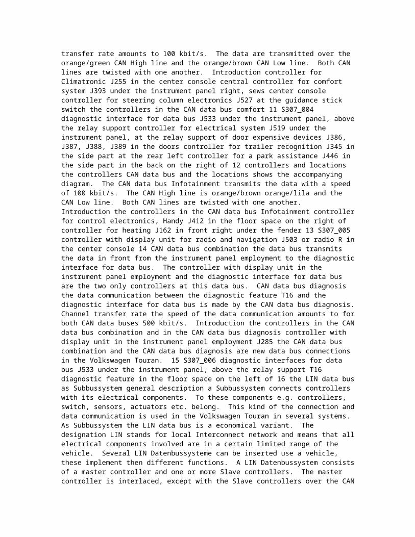
wiping" is wiped free the back window, if with switched on front wiper the reverse gear is inserted. Interval gradates once a wiping stage 1 or 2 tail wipers interval of switching on conditions: - ignition switched on - front wiper is in stage interval, stage 1 or stage 2 the recognition of the switched on stages been made by the CAN data bus comfort. The signal comes from the controller for steering column electronics. - reverse gear or back drive position inserted the recognition is made by means of the switch for backup lights, or by the drive range, the controller for automatic transmission, the CAN data bus drive, the diagnostic interface for data bus and the CAN data bus comfort. - rear flap closed the recognition is made by the central controller for comfort system. Wiper system back window CAN data bus comfort S307_035 E V12 J519 signal process rear windshield wiper J527 J533 J393 CAN data bus drive information about inserted reverse gear legend D ignition starting switch E wiper switch J393 central controller for comfort system J519 controller for electrical system J527 controller for steering column electronics J533 diagnostic interface for data bus V12 engine for rear windshield wiper D Kl. 15 45 tail interval wiping with switched on wiper position "tail interval wiping" is wiped free the back window in intervals. Switching on conditions: - ignition switched on - stage "tail interval wiping": The recognition is made by the wiper switch, the controller for steering column electronics and the CAN data bus comfort. - rear flap closed: The recognition is made by the central controller for comfort system. The dual washer pump disk washing water promotes back windows wash wiping enterprise in the stage "back windows of wash wiping enterprise" on the back window and the back window is free-wiped. Switching on conditions: - ignition switched on - stage "back windows wash wiping enterprise": The recognition is made by the wiper switch, the controller for steering column electronics and the CAN data bus comfort. - rear flap closed: The recognition is made by the central controller for comfort system. S307_036 S307_037 46 control lights and announcements the controller with display unit in the instrument panel employment heads for the display, the similar indicating instruments and the control lights. The coolant temperature gauge stands for 107 with vehicles with characteristic diagram cooling with coolant temperatures between 75 °C and °C constantly on 90 °C, with vehicles without characteristic diagram cooling with coolant temperatures between 75 °C and 115 °C constantly on 90 °C. Thus a constantly changing announcement is prevented. Instrument panel employment S307_038 the controller with display unit in the instrument panel employment J285 instrument panel employment tachometer, similar announcement speedometer, similar announcement coolant temperature, similar announcement fuel supply, similar announcement display, digital announcement LED control lights 47 display for the display the following variants are intended: Lowline with the announcements - clock - distance - daily distance - selecting range announcement Midline with additional announcements to the Lowline variant - outside temperature - multi-function announcement or - warning texts in place of multi-function announcement and outside temperature Highline with additional announcements Midline variant - transmitter announcement - warning symbols in place of multi-function announcement and outside temperature S307_039 S307_040 S307_041 20:14 20:14 20:14 km 20375 trip 167,5 P R N D S 3 km 20375 trip 167,5 km 20375 trip 167,5 P R N D S 3,7,8 l/100 km 13,5 C° 7,8 l/100km 13,5 C° Lowline variant Midline variant Highline variant P R NDS 2 48 equipment with control lights symbol control light Lowline Midline Highline warning text or warning Airbag X X X Airbag error Airbag of
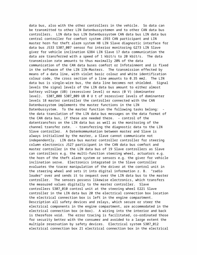
belt-taut deactivates ABS X X X ABS brake lining wear X X pictogram Brake lining lack of brake fluid X X X stop brake fluid manual a pre-heating (diesel engines) X X X dynamic oil pressure warning flashing flashing flashing pictogram stop oil pressure engine from manual electronics power control e-gas X X X electrical steering element electronics power Steering X X X electrical braking force distribution of X X X examine three times buzzer determination brake assembly X X X emergency brake tightened ESP ASR X X X turn signals on the left of X X X acoustic control of turn signals on the right of X X X acoustic control of turn signals trailer X X X high beam X X X instrument panel employment 49 symbol control light Lowline Midline Highline warning text or warning speed control governor X X X lamp loss X X X e.g. headlight low beam in front on the left of defectively rear flap door openly X X pictogram e.g. rear flap openly fuel reserve X X Pictogram request tanks once buzzers lack of cooling agent or overheating X X pictogram stop! Cooling agents examine manual three times buzzer generator X X X engine check EOBD X X X engine disturbance workshop exhaust gas workshop hood openly X X pictogram door warning! Hood! Once buzzers if v > 6 km/h fog tail light X X X oil level X X pictogram oil level examine oil sensor workshop tire pressure monitoring X X X once buzzer SHIFT LOCK X X X seat belt X X X request belt put on gong lack of washing water X X pictogram washing water fill up once buzzer going away safety device flashing flashing flashing going away safety device actively once buzzer 50 controller the controller for going away safety device J362 are integrated as during the going away safety device of the third generation in the instrument panel employment. The diagnostic connection is developed over the address word 25. Communication is possible for vehicle diagnosis only over the CAN data bus diagnosis with that -, measuring and information system VAS 5051. Going away safety device the going away safety device of the fourth generation VAS 5051 T16 CAN data bus diagnosis CAN data bus combination VAS 5051/Ä diagnosis J533 J285 legend J285 controller with display unit in the instrument panel employment J533 diagnostic interface for data bus VAS 5051 vehicle diagnosis -, measuring and information system VAS 5051/Ä diagnostic line 3 m T16 diagnostic feature S307_042 51 changes to the going away safety device of the third generation mark identification the components of the going away safety device of all company marks are different. An adjustment of components of other company marks in Volkswagen vehicles is not possible. Pre-programmed keys the vehicle keys are pre-programmed with the manufacturer with a basis coding. This basis coding contains a specific manufacturer's code. Training of the keys on a vehicle is possible only if they are programmed with the correct manufacturer's code. S307_044 S307_043 basis coding 52 going away safety device adjustment de-energising the adjustment function takes place menu-led with that vehicle diagnosis -, Messund information system VAS 5051. The personal identification number (pin) to the adjustment can be requested at present over the dealer on-line access (WOOD). At a later time the adjustment is accomplished over an on-line connection. Exchange of the engine expensive equipment the engine expensive equipment is de-energised, as during the going away safety device of the third generation. Two of the three trained components (keys and instrument panel employment) must remain in the vehicle. During the adjustment of a new controller this can take place without personal identification number. For the adjustment of a controller that was built in another vehicle already, the personal identification number is necessary. 53 exchange of the
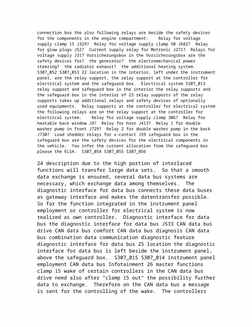
instrument panel employment the adjustment is to be accomplished as during the going away safety device of the third generation. Two of the three trained components (keys and engine expensive equipment) must likewise remain in the vehicle. The adjustment of a new instrument panel employment can take place without personal identification number. With an instrument panel employment already used becomes, as with the engine expensive equipment, which needs personal identification number. After changing the controller recognizes unknown keys for going away safety device J362. Due to its a curfew begins to run from five minutes to, in which the engine cannot be started. With an exchange of more than a Komponete all three Komponeten must be renewed, since less than two the trained Komponeten remain in the vehicle. 54 the Personalisierung the user specific attitudes of different device functions in Komfortund Infotainmentbereich is made by a control element and a display. The operation is accomplished over the control lever at the steering wheel, the menu selection over the display in the instrument panel employment. The selected attitudes are stored in the controller, which is responsible for the controlling of the respective function. The transmission of the necessary information between the controller with display unit in the instrument panel employment and the controllers takes over the CAN data bus. Comfort and Infotainmenteinstellungen S307_045 J527 J519 J393 J162 legend J162 controller for heating J285 controller with display unit in the instrument panel employment J393 central controller for comfort system J519 controller for electrical system J527 controller for steering column column electronics J533 diagnostic interface for data bus J533 J285 guidance stick switch the exact operation take you please from the operating instructions. 55 headlights One Touch attachment the H7 lamps are connected by the One Touch attachment with the reflector. The past attachment with clips and the electrical connection with a plug are void. The attachments of the lamps with a rotating motion can be solved by One Touch. Subsequently, the lamp is pulled from the attachment. You find lighting S307_060 the descriptions of function for the blocked Bi-xenon-headlights in the SSP 251 "the trade wind 2001". You infer the proceeding for replacement from a lamp the ELSA. S307_064 attachment through left turn loosen lamp from the attachment pull 56 diagnosis data exchange between that, necessary for the diagnosis, vehicle diagnosis -, measuring and information system VAS 5051 or the vehicle diagnostic and service information system VAS 5052 are made by the CAN data bus diagnosis. The transmission to the VAS 5051 is possible only over the diagnostic lines VAS 5051/Ä or VAS 5051/Ã. In the case of use of the vehicle diagnostic and service of information system 5052 the diagnostic line VAS 5052/3 is used. These diagnostic lines are suitable for a data communication on the CAN data bus diagnosis. The past k-line is used still for the diagnosis of the engine and the GET rubbing of you equipment in the OBD mode. Therefore the diagnosis with other diagnostic lines is possible only in the engine expensive equipment and in the controller for automatic transmission. Service VAS 5051 VAS 5052 VAS 5051/Ã 57 S307_051 legend J285 controller with display unit in the instrument panel employment J533 diagnostic interface for data bus T16 diagnostic feature VAS 5051 vehicle diagnosis -, measuring and information system VAS 5051/Ä diagnostic line 3 m VAS 5051/Ã diagnostic line 5 m VAS 5052 vehicle diagnostic and service information system VAS 5052/3 diagnostic line 3 m CAN data bus drive CAN data bus comfort CAN data bus Infotainment CAN data bus combination CAN data bus diagnosis T16 J285 VAS 5051/Ä k-line J533 VAS
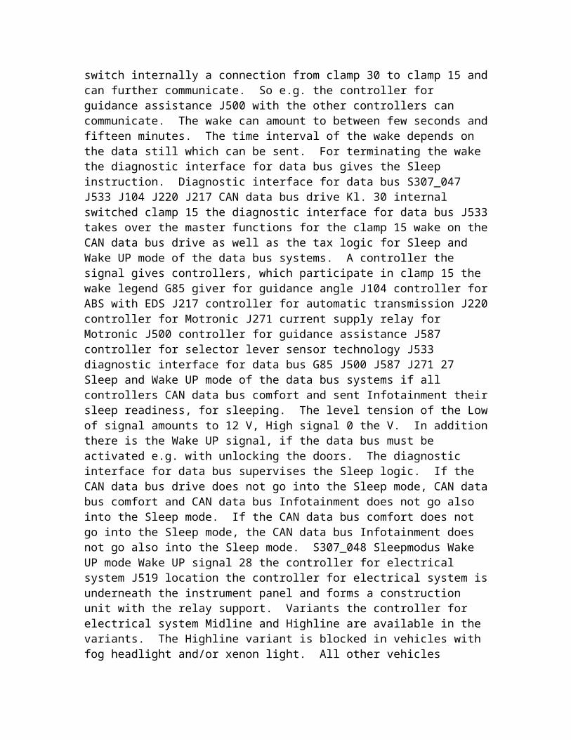
5052/3 58 1. Which data bus systems are used in the Volkswagen Touran? A) the CAN data bus and the LIN data bus. b) the MOSFET data bus, the LIN data bus and the MOST bus. C) the D2B-Datenbus, the A bus and the CAN bus. 2. Where is the diagnostic interface for data bus? A) in the instrument panel employment. b) under the center console, beside the controller for Airbag. C) under the instrument panel, above the relay support. 3. Which controllers belong to the CAN data bus combination? A) the controller for electrical system, the controller for automatic transmission and the controller for trailer recognition. b) the controller with display unit in the instrument panel employment and the diagnostic interface for data bus. C) the controller for Motronic and the diagnostic feature. 4. The LIN data bus transmits the data with a speed of?? A) 1 kbit/s to 20 kbit/s. b) 100 kbit/s to 500 kbit/s. C) 21 Mbit/s. Examine their knowledge 59 5. Which functions are steered by the controller for electrical system? A) the turn signal price increase, the heatable back window, the fuel pump advance. b) the wiper for the front and back window, the zentralverriegelung, instrument lights. C) the load management, the generator before excitation, the starter barrier. 6. Wherein does the major task of the load management lie? to ensure A) that always sufficient electricity stands for starting for order. b) as electronic loading recognition warns it the driver, if the vehicle is overloaded. C) you is overloaded prevented that the engine by inappropriate operation. 7. On what is with the diagnosis with the vehicle - to respect measuring and information system VAS 5051 at the Touran? A) to the diagnosis may be used only the diagnostic lines VAS 5051/Ä and VAS 5051/Ã. b) the diagnosis can be accomplished in all ranges with the V.A.G 1551 or V.A.G 1552. C) the diagnosis is possible only with the VAS 9119. Solutions: 1. A 2. C 3. b 4. A 5. A, C 6. A 7. A only for the internal use © VOLKSWAGEN AG, wolf castle all rights as well as technical subject to change 000,2811,27,00 technical conditions 02/03?