Embed Size (px)
Citation preview
1
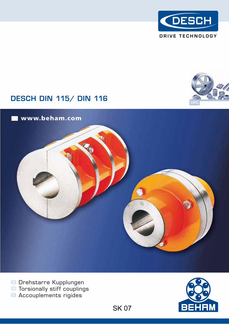
DESCH DIN 115/ DIN 116
SK 07D
GB
F
I
E
Drehstarre KupplungenTorsionally stif f couplingsAccouplements rigidesGiunti torsionalmente rigidiAcoplamientos rígidos
www.beham.com
SK 07
www.beham.com www.beham.com
W H E N F U L L P O W E R I S N E E D E D
2
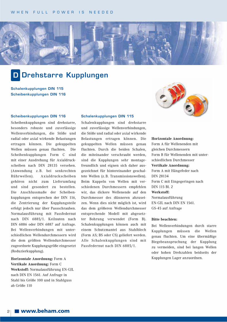
Drehstarre Kupplungen
Scheibenkupplungen DIN 116
Scheibenkupplungen sind drehstarre,besonders robuste und zuverlässigeWellenverbindungen, die Stöße und radial oder axial wirkende Belastungen ertragen können. Die gekuppelten Wellen müssen genau fluchten. Die Scheibenkupplungen Form C sindmit einer Ausdrehung für Axialdruck-scheiben nach DIN 28135 versehen.(Anwendung z. B. bei senkrechten Rührwellen). Axialdruckscheiben gehören nicht zum Lieferumfang und sind gesondert zu bestellen.Die Anschlussmaße der Scheiben-kupplungen entsprechen der DIN 116,
die Zentrierung der Kupplungsteile erfolgt jedoch nur über Passschrauben. Normalausführung mit Passfedernut
nach DIN 6885/1. Keilnuten nach DIN 6886 oder DIN 6887 auf Anfrage. Bei Wellenverbindungen mit unter-
schiedlichen Wellendurchmessern wird die dem größten Wellendurchmesser zugeordnete Kupplungsgröße eingesetzt
(Reduzierkupplung).
D
Horizontale Anordnung: Form AVertikale Anordnung: Form CWerkstoff: Normalausführung EN-GJL
nach DIN EN 1561. Auf Anfrage in Stahl bis Größe 100 und in Stahlguss ab Größe 110
Schalenkupplungen DIN 115
Schalenkupplungen sind drehstarre und zuverlässige Wellenverbindungen, die Stöße und radial oder axial wirkendeBelastungen ertragen können. Die gekuppelten Wellen müssen genau fluchten. Durch die beiden Schalen, die miteinander verschraubt werden, sind die Kupplungen sehr montage-freundlich und eignen sich daher aus-gezeichnet für hintereinander geschal-tete Wellen (z. B. Transmissionswellen). Beim Kuppeln von Wellen mit ver-schiedenen Durchmessern empfehlen wir, das dickere Wellenende auf den Durchmesser des dünneren abzuset-zen. Wenn dies nicht möglich ist, wird
das dem größeren Wellendurchmesser
entsprechende Modell mit abgesetz-ter Bohrung verwendet (Form B). Schalenkupplungen können auch mit
einem Schutzmantel aus Stahlblech (Form AS; BS oder CS) geliefert werden. Alle Schalenkupplungen sind mit Passfedernut nach DIN 6885/1.
Horizontale Anordnung:Form A für Wellenenden mit gleichen DurchmessernForm B für Wellenenden mit unter-schiedlichen DurchmesserVertikale Anordnung:Form A mit Hängefeder nach DIN 28134Form C mit Eingegeringen nach DIN 115 Bl. 2Werkstoff:Normalausführung
EN-GJL nach DIN EN 1561.
GS-45 auf Anfrage
Bitte beachten:
Bei Wellenverbindungen durch starreKupplungen müssen die Wellengenau fluchten. Um eine übermäßige
Biegebeanspruchung der Kupplungzu vermeiden, sind bei langen Wellen oder hohen Drehzahlen beidseits der Kupplungen Lager anzuordnen.
Schalenkupplungen DIN 115
Scheibenkupplungen DIN 116
3
Torsionally stiff couplingsGB
Clamp couplings DIN 115
Flange couplings DIN 116
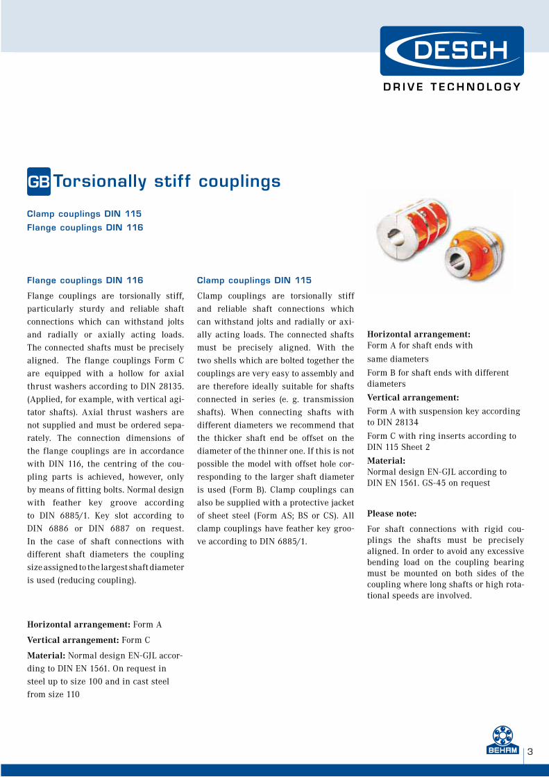
Flange couplings DIN 116
Flange couplings are torsionally stiff, particularly sturdy and reliable shaft connections which can withstand jolts and radially or axially acting loads. The connected shafts must be precisely aligned. The flange couplings Form C are equipped with a hollow for axial thrust washers according to DIN 28135. (Applied, for example, with vertical agi-tator shafts). Axial thrust washers are not supplied and must be ordered sepa-rately. The connection dimensions of the flange couplings are in accordance with DIN 116, the centring of the cou-pling parts is achieved, however, only
by means of fitting bolts. Normal design with feather key groove according to DIN 6885/1. Key slot according to
DIN 6886 or DIN 6887 on request. In the case of shaft connections with different shaft diameters the coupling
size assigned to the largest shaft diameteris used (reducing coupling).
Horizontal arrangement: Form A
Vertical arrangement: Form C
Material: Normal design EN-GJL accor-ding to DIN EN 1561. On request in
steel up to size 100 and in cast steel from size 110
Clamp couplings DIN 115
Clamp couplings are torsionally stiff and reliable shaft connections which can withstand jolts and radially or axi-ally acting loads. The connected shafts must be precisely aligned. With the two shells which are bolted together the couplings are very easy to assembly and are therefore ideally suitable for shafts connected in series (e. g. transmission shafts). When connecting shafts with different diameters we recommend that the thicker shaft end be offset on the diameter of the thinner one. If this is not possible the model with offset hole cor-responding to the larger shaft diameter is used (Form B). Clamp couplings can
also be supplied with a protective jacket
of sheet steel (Form AS; BS or CS). All clamp couplings have feather key groo-ve according to DIN 6885/1.
Horizontal arrangement:Form A for shaft ends with
same diameters
Form B for shaft ends with different diameters
Vertical arrangement:
Form A with suspension key according to DIN 28134
Form C with ring inserts according to DIN 115 Sheet 2
Material: Normal design EN-GJL according to DIN EN 1561. GS-45 on request
Please note:
For shaft connections with rigid cou-plings the shafts must be precisely aligned. In order to avoid any excessive bending load on the coupling bearing must be mounted on both sides of the coupling where long shafts or high rota-tional speeds are involved.
www.beham.com www.beham.com
W H E N F U L L P O W E R I S N E E D E D
4
Accouplements rigidesF
Accouplements à disques DIN 116
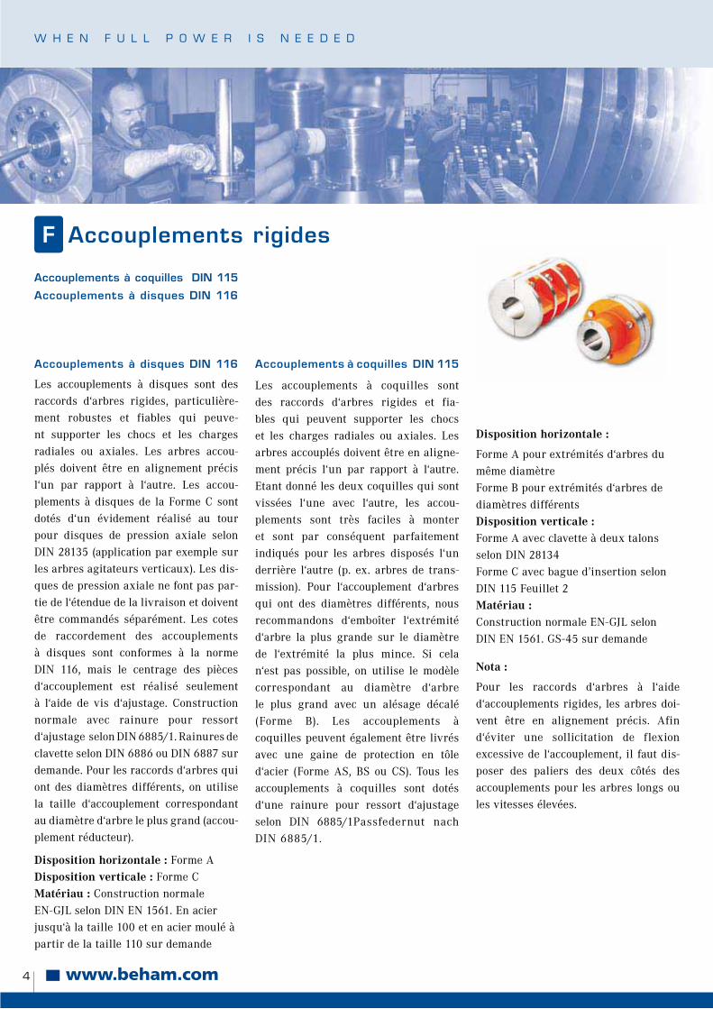
Les accouplements à disques sont des raccords d‘arbres rigides, particulière-ment robustes et fiables qui peuve-nt supporter les chocs et les charges radiales ou axiales. Les arbres accou-plés doivent être en alignement précis l‘un par rapport à l‘autre. Les accou-plements à disques de la Forme C sont dotés d‘un évidement réalisé au tour pour disques de pression axiale selon DIN 28135 (application par exemple sur les arbres agitateurs verticaux). Les dis-ques de pression axiale ne font pas par-tie de l‘étendue de la livraison et doivent être commandés séparément. Les cotes
de raccordement des accouplements à disques sont conformes à la norme DIN 116, mais le centrage des pièces
d‘accouplement est réalisé seulement à l‘aide de vis d‘ajustage. Construction normale avec rainure pour ressort
d‘ajustage selon DIN 6885/1. Rainures de clavette selon DIN 6886 ou DIN 6887 sur demande. Pour les raccords d‘arbres qui
ont des diamètres différents, on utilisela taille d‘accouplement correspondant au diamètre d‘arbre le plus grand (accou-plement réducteur).
Disposition horizontale : Forme A
Disposition verticale : Forme CMatériau : Construction normale
EN-GJL selon DIN EN 1561. En acier jusqu‘à la taille 100 et en acier moulé à partir de la taille 110 sur demande
Accouplements à coquilles DIN 115
Les accouplements à coquilles sont des raccords d‘arbres rigides et fia-bles qui peuvent supporter les chocs et les charges radiales ou axiales. Les arbres accouplés doivent être en aligne-ment précis l‘un par rapport à l‘autre. Etant donné les deux coquilles qui sont vissées l‘une avec l‘autre, les accou-plements sont très faciles à monteret sont par conséquent parfaitement indiqués pour les arbres disposés l‘un derrière l‘autre (p. ex. arbres de trans-mission). Pour l‘accouplement d‘arbres qui ont des diamètres différents, nous recommandons d‘emboîter l‘extrémité
d‘arbre la plus grande sur le diamètrede l‘extrémité la plus mince. Si cela n‘est pas possible, on utilise le modèle
correspondant au diamètre d‘arbre le plus grand avec un alésage décalé (Forme B). Les accouplements à
coquilles peuvent également être livrés avec une gaine de protection en tôle d‘acier (Forme AS, BS ou CS). Tous les
accouplements à coquilles sont dotés d‘une rainure pour ressort d‘ajustage selon DIN 6885/1Passfedernut nach DIN 6885/1.
Disposition horizontale :
Forme A pour extrémités d‘arbres du même diamètreForme B pour extrémités d‘arbres de diamètres différentsDisposition verticale : Forme A avec clavette à deux talons selon DIN 28134Forme C avec bague d’insertion selon DIN 115 Feuillet 2Matériau : Construction normale EN-GJL selon
DIN EN 1561. GS-45 sur demande
Nota :
Pour les raccords d‘arbres à l‘aide d‘accouplements rigides, les arbres doi-vent être en alignement précis. Afin d‘éviter une sollicitation de flexion excessive de l‘accouplement, il faut dis-
poser des paliers des deux côtés des accouplements pour les arbres longs ou les vitesses élevées.
Accouplements à coquilles DIN 115
Accouplements à disques DIN 116
5
Giunti torsionalmente rigidiI
Giunti a flangia DIN 116
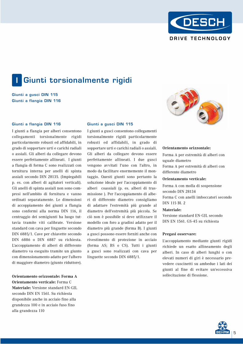
I giunti a flangia per alberi consentonocollegamenti torsionalmente rigidi particolarmente robusti ed affidabili, in grado di sopportare urti e carichi radiali o assiali. Gli alberi da collegare devono essere perfettamente allineati. I giunti a flangia di forma C sono realizzati con tornitura interna per anelli di spinta assiali secondo DIN 28135. (Impiegabili p. es. con alberi di agitatori verticali). Gli anelli di spinta assiali non sono com-presi nell‘ambito di fornitura e vanno ordinati separatamente. Le dimensioni di accoppiamento dei giunti a flangia sono conformi alla norma DIN 116, il
centraggio dei semigiunti ha luogo tut-tavia tramite viti calibrate. Versione standard con cava per linguette secondo
DIN 6885/1. Cave per chiavette secondoDIN 6886 o DIN 6887 su richiesta. L‘accoppiamento di alberi di differente
diametro va eseguito tramite un giunto con dimensionamento adatto per l‘albero di maggiore diametro (giunto riduttore).
Orientamento orizzontale: Forma AOrientamento verticale: Forma C
Materiale: Versione standard EN-GJL secondo DIN EN 1561. Su richiesta disponibile anche in acciaio fino alla
grandezza 100 e in acciaio fuso fino alla grandezza 110
Giunti a gusci DIN 115
I giunti a gusci consentono collegamenti torsionalmente rigidi particolarmente robusti ed affidabili, in grado di sopportare urti e carichi radiali o assiali.Gli alberi da collegare devono essereperfettamente allineati. I due gusci vengono avvitati l‘uno con l‘altro, in modo da facilitare enormemente il mon-taggio. Questi giunti sono pertanto la soluzione ideale per l‘accoppiamento di alberi coassiali (p. es. alberi di tras-missione ). Per l‘accoppiamento di albe-ri di differente diametro consigliamo di adattare l‘estremità più grande al diametro dell‘estremità più piccola. Se ciò non è possibile si deve utilizzare il
modello con foro a gradini adatto per il
diametro più grande (forma B). I giunti a gusci possono essere forniti anche con rivestimento di protezione in acciaio
(forma AS; BS o CS). Tutti i giunti a gusci sono realizzati con cava per linguette secondo DIN 6885/1.
Orientamento orizzontale:
Forma A per estremità di alberi con uguale diametroForma A per estremità di alberi con differente diametro
Orientamento verticale:
Forma A con molla di sospensione secondo DIN 28134Forma C con anelli imboccatori secondo DIN 115 Bl. 2
Materiale: Versione standard EN-GJL secondo DIN EN 1561. GS-45 su richiesta
Pregasi osservare:
L‘accoppiamento mediante giunti rigidi richiede un esatto allineamento degli
alberi. In caso di alberi lunghi o con elevati numeri di giri è necessario pre-vedere cuscinetti su ambedue i lati dei
giunti al fine di evitare un‘eccessiva sollecitazione di flessione.
Giunti a gusci DIN 115
Giunti a flangia DIN 116
www.beham.com www.beham.com
W H E N F U L L P O W E R I S N E E D E D
6
Acoplamientos rígidosE
Acoplamientos de disco DIN 116
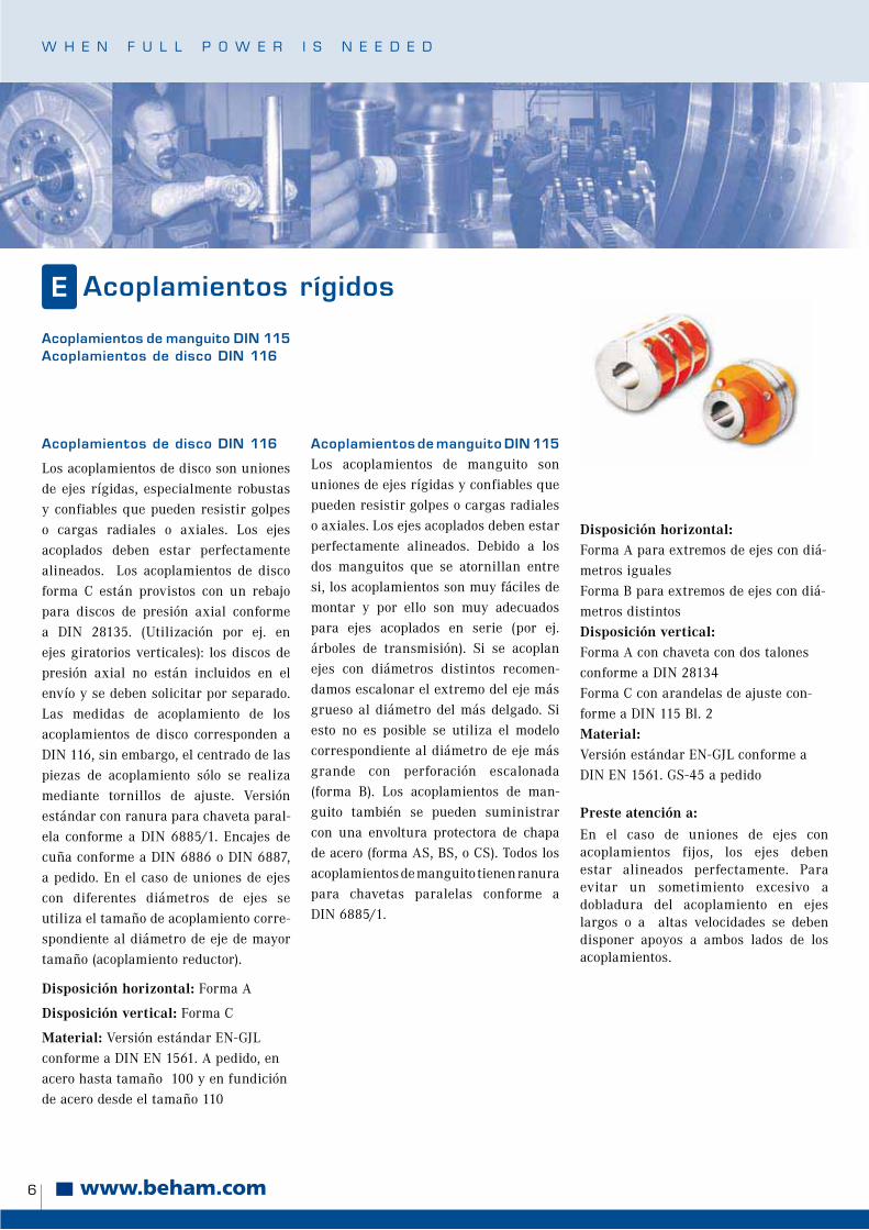
Los acoplamientos de disco son uniones de ejes rígidas, especialmente robustas y confiables que pueden resistir golpes o cargas radiales o axiales. Los ejes acoplados deben estar perfectamente alineados. Los acoplamientos de disco forma C están provistos con un rebajo para discos de presión axial conforme a DIN 28135. (Utilización por ej. en ejes giratorios verticales): los discos de presión axial no están incluidos en el envío y se deben solicitar por separado. Las medidas de acoplamiento de los acoplamientos de disco corresponden a DIN 116, sin embargo, el centrado de las
piezas de acoplamiento sólo se realiza mediante tornillos de ajuste. Versión estándar con ranura para chaveta paral-
ela conforme a DIN 6885/1. Encajes de cuña conforme a DIN 6886 o DIN 6887, a pedido. En el caso de uniones de ejes
con diferentes diámetros de ejes se utiliza el tamaño de acoplamiento corre-spondiente al diámetro de eje de mayor
tamaño (acoplamiento reductor).
Disposición horizontal: Forma A
Disposición vertical: Forma C
Material: Versión estándar EN-GJL conforme a DIN EN 1561. A pedido, en
acero hasta tamaño 100 y en fundición de acero desde el tamaño 110
Acoplamientos de manguito DIN 115
Los acoplamientos de manguito son uniones de ejes rígidas y confiables que pueden resistir golpes o cargas radiales o axiales. Los ejes acoplados deben estar perfectamente alineados. Debido a los dos manguitos que se atornillan entre si, los acoplamientos son muy fáciles de montar y por ello son muy adecuados para ejes acoplados en serie (por ej. árboles de transmisión). Si se acoplan ejes con diámetros distintos recomen-damos escalonar el extremo del eje más grueso al diámetro del más delgado. Si esto no es posible se utiliza el modelocorrespondiente al diámetro de eje más grande con perforación escalonada
(forma B). Los acoplamientos de man-
guito también se pueden suministrar con una envoltura protectora de chapa de acero (forma AS, BS, o CS). Todos los
acoplamientos de manguito tienen ranura para chavetas paralelas conforme a DIN 6885/1.
Disposición horizontal:Forma A para extremos de ejes con diá-metros iguales Forma B para extremos de ejes con diá-metros distintosDisposición vertical: Forma A con chaveta con dos talones conforme a DIN 28134Forma C con arandelas de ajuste con-forme a DIN 115 Bl. 2Material: Versión estándar EN-GJL conforme a DIN EN 1561. GS-45 a pedido
Preste atención a:
En el caso de uniones de ejes conacoplamientos fijos, los ejes debenestar alineados perfectamente. Para evitar un sometimiento excesivo a dobladura del acoplamiento en ejes largos o a altas velocidades se deben disponer apoyos a ambos lados de los acoplamientos.
Acoplamientos de manguito DIN 115Acoplamientos de disco DIN 116
7
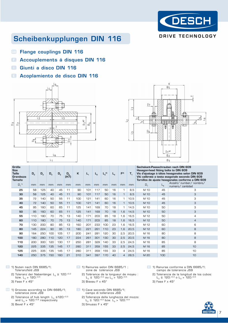
Scheibenkupplungen DIN 116
Flange couplings DIN 116
Accouplements á disques DIN 116
Giunti a disco DIN 116
Acoplamiento de disco DIN 116
GB
F
I
E
GrößeSizeTailleGrandezzaTamaño
D2 D3 D4 D5 D6(H7)
K L1 L2 L32) L4 F3) T1
Sechskant-Passschrauben nach DIN 609Hexagon-head fitting bolts to DIN 609Vis d‘ajustage à têtes hexagonales selon DIN 609Viti calibrate a testa esagonale secondo DIN 609Tornillos de ajuste hexagonales conforme a DIN 609
D11) mm mm mm mm mm mm mm mm mm mm mm mm D7 L6
Anzahl/ number/ nombre/ numero/ cantidad
25 58 125 40 45 11 90 101 117 50 16 1 8,5 M 10 45 3
30 58 125 40 45 11 90 101 117 50 16 1 8,5 M 10 45 3
35 72 140 50 55 11 100 121 141 60 16 1 10,5 M 10 45 3
40 72 140 50 55 11 100 121 141 60 16 1 10,5 M 10 45 3
45 95 160 60 65 11 125 141 169 70 18 1 14,5 M 10 50 3
50 95 160 60 65 11 125 141 169 70 18 1,6 14,5 M 10 50 3
55 110 180 70 75 13 140 171 203 85 18 1,6 16,5 M 12 50 4
60 110 180 70 75 13 140 171 203 85 18 1,6 16,5 M 12 50 4
70 130 200 80 85 13 160 201 233 100 23 1,6 16,5 M 12 60 6
80 145 224 90 95 13 180 221 261 110 23 1,6 20,5 M 12 60 8
90 164 250 100 105 17 200 241 281 120 30 2,5 20,5 M 16 80 8
100 180 280 110 120 17 224 261 301 130 30 2,5 20,5 M 16 80 8
110 200 300 120 130 17 250 281 329 140 33 2,5 24,5 M 16 85 8
120 225 335 135 145 17 280 311 359 155 33 2,5 24,5 M 16 85 10
125 225 335 135 145 17 280 311 359 155 33 4 24,5 M 16 85 10
140 250 375 150 160 21 310 341 397 170 40 4 28,5 M 20 100 10
1) Nuten nach DIN 6685/1;Toleranzfeld JS9
2) Toleranz der Nabenlänge: L3 � 120:+0,3
bzw. L3 > 120:+0,5
3) Fase F x 45°
1) Grooves according to DIN 6685/1; tolerance zone JS9
2) Tolerance of hub length: L3 �120:+0,3
and L3 > 120:+0,5 respectively
3) Bevel F x 45°
F
GB I
D E1) Rainures selon DIN 6685/1 ; zone de tolérance JS9
2) Tolérance de la longueur de moyeu : L3 � 120:+0,3 ou L3 > 120:+0,5
3) Biseau F x 45°
1) Cave secondo DIN 6685/1;campo di tolleranza JS9
2) Tolleranza della lunghezza del mozzo: L3 � 120:+0,3 bzw. L3 > 120:+0,5
3) Smusso F x 45°
1) Ranuras conforme a DIN 6685/1; campo de tolerancia JS9
2) Tolerancia de la longitud de los cubos: L3 � 120:+0,3 o L3 > 120:+0,5
3) Fase F x 45°
www.beham.com www.beham.com
W H E N F U L L P O W E R I S N E E D E D
8
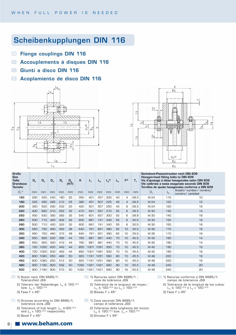
Scheibenkupplungen DIN 116
Flange couplings DIN 116
Accouplements á disques DIN 116
Giunti a disco DIN 116
Acoplamiento de disco DIN 116
GB
F
I
E
GrößeSizeTailleGrandezzaTamaño
D2 D3 D4 D5 D6(H7)
K L1 L2 L32) L4 F3) T1
Sechskant-Passschrauben nach DIN 609Hexagon-head fitting bolts to DIN 609Vis d‘ajustage à têtes hexagonales selon DIN 609Viti calibrate a testa esagonale secondo DIN 609Tornillos de ajuste hexagonales conforme a DIN 609
D11) mm mm mm mm mm mm mm mm mm mm mm mm D7 L6
Anzahl/ number/ nombre/ numero/ cantidad
160 290 425 240 180 25 350 401 457 200 40 4 28,5 M 24 110 10
180 325 450 265 212 25 380 451 507 225 45 4 28,5 M 24 120 12
200 360 500 290 232 25 420 501 557 250 45 6 28,5 M 24 120 16
220 400 560 310 252 32 470 541 597 270 52 6 28,5 M 30 140 14
250 450 630 390 282 32 540 601 657 300 52 6 28,8 M 30 140 16
260 500 710 420 302 32 600 681 741 340 55 6 30,5 M 30 150 16
280 500 710 420 322 32 600 681 741 340 55 6 30,5 M 30 150 16
300 560 750 460 352 38 640 761 831 380 62 10 35,5 M 36 170 16
320 560 750 460 372 38 640 761 831 380 62 10 35,5 M 36 170 16
340 650 900 520 392 44 760 881 961 440 70 10 40,5 M 42 190 14
360 650 900 520 412 44 760 881 961 440 70 10 40,5 M 42 190 14
380 720 1000 600 442 44 850 1001 1091 500 70 10 45,5 M 42 190 16
400 720 1000 600 462 44 850 1001 1091 500 70 10 45,5 M 42 190 16
420 800 1060 650 482 50 920 1161 1251 580 80 10 45,5 M 48 220 16
450 800 1060 650 512 50 920 1161 1251 580 80 10 45,5 M 48 220 16
460 900 1180 800 532 50 1030 1321 1421 660 90 10 50,5 M 48 240 20
500 900 1180 800 572 50 1030 1321 1421 660 90 16 50,5 M 48 240 20
1) Nuten nach DIN 6685/1;Toleranzfeld JS9
2) Toleranz der Nabenlänge: L3 � 120:+0,3
bzw. L3 > 120:+0,5
3) Fase F x 45°
1) Grooves according to DIN 6685/1; tolerance zone JS9
2) Tolerance of hub length: L3 �120:+0,3
and L3 > 120:+0,5 respectively
3) Bevel F x 45°
F
GB I
D E1) Rainures selon DIN 6685/1 ; zone de tolérance JS9
2) Tolérance de la longueur de moyeu : L3 � 120:+0,3 ou L3 > 120:+0,5
3) Biseau F x 45°
1) Cave secondo DIN 6685/1;campo di tolleranza JS9
2) Tolleranza della lunghezza del mozzo: L3 � 120:+0,3 bzw. L3 > 120:+0,5
3) Smusso F x 45°
1) Ranuras conforme a DIN 6685/1; campo de tolerancia JS9
2) Tolerancia de la longitud de los cubos: L3 � 120:+0,3 o L3 > 120:+0,5
3) Fase F x 45°
9
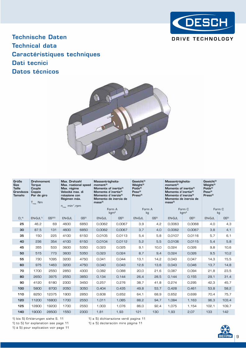
GrößeSizeTailleGrandezzaTamaño
DrehmomentTorqueCoupleCoppia Par de giro
Tmax. Nm
Max. DrehzahlMax. roational speedMax. régimeVelocitá max. di rotazione conRégimen máx.
nmax. min-1,rpm
Massenträgheits-moment3)
Moments of inertia3)
Moments d´inertie3)
Momento d´inerzia3)
Momento de inercia de masa3)
Form Akgm2
Gewicht3)
Weight3)
Poids3)
Peso3)
Preso3)
Form Akg
Massenträgheits-moment3)
Moments of inertia3)
Moments d´inertie3)
Momento d´inerzia3)
Momento de inercia de masa3)
Form Ckgm2
Gewicht3)
Weight3)
Poids3)
Peso3)
Preso3)
Form Ckg
D14) EN-GJL1) GS2)5) EN-GJL GS5) EN-GJL GS5) EN-GJL GS5) EN-GJL GS5) EN-GJL GS5)
25 46,2 69 4600 6850 0,0062 0,0067 3,9 4,2 0,0063 0,0068 4,0 4,3
30 87,5 131 4600 6850 0,0062 0,0067 3,7 4,0 0,0062 0,0067 3,8 4,1
35 150 225 4100 6150 0,0105 0,0113 5,4 5,8 0,0107 0,0116 5,7 6,1
40 236 354 4100 6150 0,0104 0,0112 5,2 5,5 0,0106 0,0115 5,4 5,8
45 355 533 3600 5350 0,023 0,025 9,1 10,0 0,024 0,026 9,8 10,6
50 515 773 3600 5350 0,023 0,024 8,7 9,4 0,024 0,026 9,5 10,2
55 730 1095 3200 4750 0,041 0,044 13,1 14,2 0,043 0,047 14,3 15,5
60 975 1463 3200 4750 0,040 0,043 12,6 13,6 0,043 0,046 13,7 14,8
70 1700 2550 2850 4300 0,082 0,088 20,0 21,6 0,087 0,094 21,8 23,5
80 2650 3975 2550 3850 0,134 0,144 26,4 28,5 0,144 0,155 29,1 31,4
90 4120 6180 2300 3450 0,257 0,276 38,7 41,8 0,274 0,295 42,3 45,7
100 5800 8700 2050 3050 0,404 0,435 49,8 53,7 0,428 0,461 53,8 58,2
110 8250 12375 1900 2850 0,608 0,652 64,1 68,9 0,652 0,699 70,4 75,7
120 11200 16800 1700 2550 1,011 1,085 88,2 94,7 1,084 1,163 96,3 103,4
125 12800 19200 1700 2550 1,003 1,076 86,0 92,4 1,075 1,154 102,1 109,7
140 19000 28500 1550 2300 1,81 1,93 121 130 1,93 2,07 133 142
Technische DatenTechnical data Caractéristiques techniquesDati tecniciDatos técnicos
1) bis 5) Erklärungen siehe S. 11
1) to 5) for explanation see page 11
1) á 5) pour explication voir page 11
1) a 5) dichiarazione verdi pagina 11
1) a 5) declaración mire página 11
www.beham.com www.beham.com
W H E N F U L L P O W E R I S N E E D E D
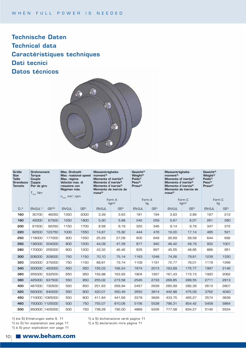
10
GrößeSizeTailleGrandezzaTamaño
DrehmomentTorqueCoupleCoppia Par de giro
Tmax. Nm
Max. DrehzahlMax. roational speedMax. régimeVelocitá max. di rotazione conRégimen máx.
nmax. min-1,rpm
Massenträgheits-moment3)
Moments of inertia3)
Moments d´inertie3)
Momento d´inerzia3)
Momento de inercia de masa3)
Form Akgm2
Gewicht3)
Weight3)
Poids3)
Peso3)
Preso3)
Form Akg
Massenträgheits-moment3)
Moments of inertia3)
Moments d´inertie3)
Momento d´inerzia3)
Momento de inercia de masa3)
Form Ckgm2
Gewicht3)
Weight3)
Poids3)
Peso3)
Preso3)
Form Ckg
D14) EN-GJL1) GS2)5) EN-GJL GS5) EN-GJL GS5) EN-GJL GS5) EN-GJL GS5) EN-GJL GS5)
160 30700 46050 1350 2000 3,39 3,63 181 194 3,63 3,89 197 212
180 45000 67500 1250 1900 5,30 5,68 242 259 5,67 6,07 261 280
200 61500 92250 1150 1700 8,58 9,19 322 346 9,14 9,79 347 372
220 82500 123750 1000 1550 14,87 15,92 444 476 16,00 17,14 485 521
250 118000 177000 900 1350 25,29 27,09 605 649 26,69 28,59 644 692
260 136000 204000 800 1200 44,09 47,28 877 942 46,42 49,79 932 1001
280 170000 255000 800 1200 43,32 46,46 835 897 45,55 48,85 886 951
300 206000 309000 750 1150 70,10 75,14 1163 1248 74,26 79,61 1239 1330
320 250000 375000 750 1150 68,81 73,74 1109 1191 72,77 78,01 1179 1266
340 300000 450000 650 950 155,03 166,24 1874 2013 163,89 175,77 1997 2146
360 355000 532500 650 950 152,88 163,93 1804 1937 161,43 173,13 1920 2062
380 425000 637500 550 850 255,02 273,58 2545 2733 269,85 289,55 2711 2913
400 487000 730500 550 850 251,63 269,94 2457 2639 265,99 285,39 2613 2807
420 560000 840000 550 800 420,01 450,49 3552 3814 442,88 475,09 3762 4040
450 710000 1065000 550 800 411,84 441,69 3378 3628 433,75 465,27 3574 3838
460 750000 1125000 500 750 755,07 810,06 5156 5538 796,31 854,42 5458 5864
500 950000 1425000 500 750 738,28 792,00 4866 5226 777,58 834,27 5142 5524
Technische DatenTechnical data Caractéristiques techniquesDati tecniciDatos técnicos
1) bis 5) Erklärungen siehe S. 11
1) to 5) for explanation see page 11
1) á 5) pour explication voir page 11
1) a 5) dichiarazione verdi pagina 11
1) a 5) declaración mire página 11
11
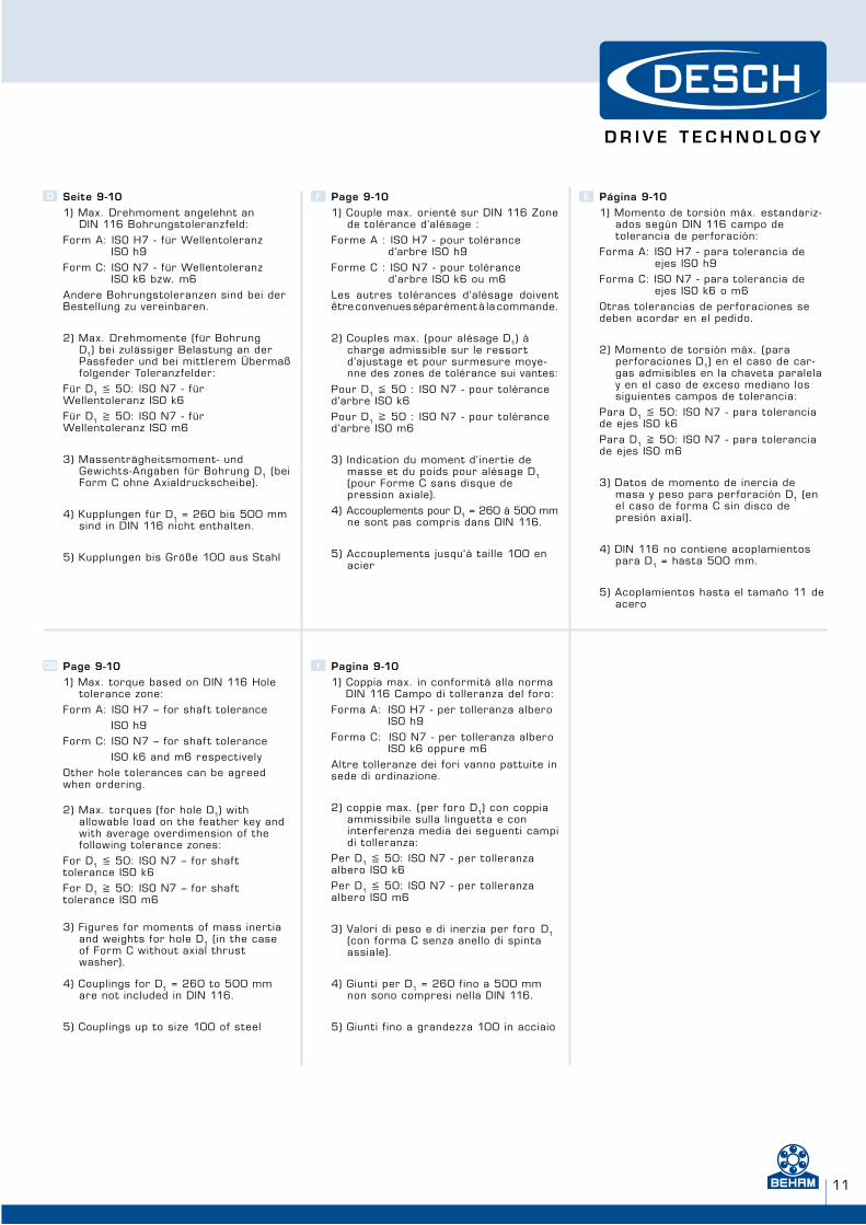
Seite 9-101) Max. Drehmoment angelehnt an
DIN 116 Bohrungstoleranzfeld:
Form A: ISO H7 - für Wellentoleranz ISO h9
Form C: ISO N7 - für Wellentoleranz ISO k6 bzw. m6
Andere Bohrungstoleranzen sind bei der Bestellung zu vereinbaren.
2) Max. Drehmomente (für Bohrung D1) bei zulässiger Belastung an der
Passfeder und bei mit t lerem Übermaß folgender Toleranzfelder:
Für D1 � 50: ISO N7 - für Wellentoleranz ISO k6
Für D1 � 50: ISO N7 - für Wellentoleranz ISO m6
3) Massenträgheitsmoment- und Gewichts-Angaben für Bohrung D1 (bei
Form C ohne Axialdruckscheibe).
4) Kupplungen für D1 = 260 bis 500 mm sind in DIN 116 nicht enthalten.
5) Kupplungen bis Größe 100 aus Stahl
GB
F
I
D E
Page 9-101) Max. torque based on DIN 116 Hole
tolerance zone:
Form A: ISO H7 – for shaf t tolerance
ISO h9
Form C: ISO N7 – for shaf t tolerance
ISO k6 and m6 respectively
Other hole tolerances can be agreed when ordering.
2) Max. torques (for hole D1) with allowable load on the feather key and with average overdimension of the following tolerance zones:
For D1 � 50: ISO N7 – for shaf t tolerance ISO k6
For D1 � 50: ISO N7 – for shaf t tolerance ISO m6
3) Figures for moments of mass inertia and weights for hole D1 (in the case of Form C without axial thrust washer).
4) Couplings for D1 = 260 to 500 mm are not included in DIN 116.
5) Couplings up to size 100 of steel
Page 9-101) Couple max. orienté sur DIN 116 Zone
de tolérance d‘alésage :
Forme A : ISO H7 - pour tolérance d‘arbre ISO h9
Forme C : ISO N7 - pour tolérance d‘arbre ISO k6 ou m6
Les autres tolérances d‘alésage doivent être convenues séparément à la commande.
2) Couples max. (pour alésage D1) àcharge admissible sur le ressort d‘ajustage et pour surmesure moye-nne des zones de tolérance sui vantes:
Pour D1 � 50 : ISO N7 - pour tolérance d‘arbre ISO k6
Pour D1 � 50 : ISO N7 - pour tolérance d‘arbre ISO m6
3) Indication du moment d‘inertie de masse et du poids pour alésage D1(pour Forme C sans disque de pression axiale).
4) Accouplements pour D1 = 260 à 500 mm ne sont pas compris dans DIN 116.
5) Accouplements jusqu‘à taille 100 en acier
Pagina 9-101) Coppia max. in conformità alla norma
DIN 116 Campo di tolleranza del foro:
Forma A: ISO H7 - per tolleranza albero ISO h9
Forma C: ISO N7 - per tolleranza albero ISO k6 oppure m6
Altre tolleranze dei fori vanno pattuite in sede di ordinazione.
2) coppie max. (per foro D1) con coppia ammissibile sulla linguetta e con interferenza media dei seguenti campi di tolleranza:
Per D1 � 50: ISO N7 - per tolleranza albero ISO k6
Per D1 � 50: ISO N7 - per tolleranza albero ISO m6
3) Valori di peso e di inerzia per foro D1(con forma C senza anello di spinta assiale).
4) Giunti per D1 = 260 fino a 500 mm non sono compresi nella DIN 116.
5) Giunti f ino a grandezza 100 in acciaio
Página 9-101) Momento de torsión máx. estandariz-
ados según DIN 116 campo de tolerancia de perforación:
Forma A: ISO H7 - para tolerancia de ejes ISO h9
Forma C: ISO N7 - para tolerancia de ejes ISO k6 o m6
Otras tolerancias de perforaciones se deben acordar en el pedido.
2) Momento de torsión máx. (para perforaciones D1) en el caso de car-gas admisibles en la chaveta paralela y en el caso de exceso mediano los siguientes campos de tolerancia:
Para D1 � 50: ISO N7 - para tolerancia de ejes ISO k6
Para D1 � 50: ISO N7 - para tolerancia de ejes ISO m6
3) Datos de momento de inercia de masa y peso para perforación D1 (en el caso de forma C sin disco de presión axial).
4) DIN 116 no contiene acoplamientos para D1 = hasta 500 mm.
5) Acoplamientos hasta el tamaño 11 de acero
www.beham.com www.beham.com
W H E N F U L L P O W E R I S N E E D E D
12
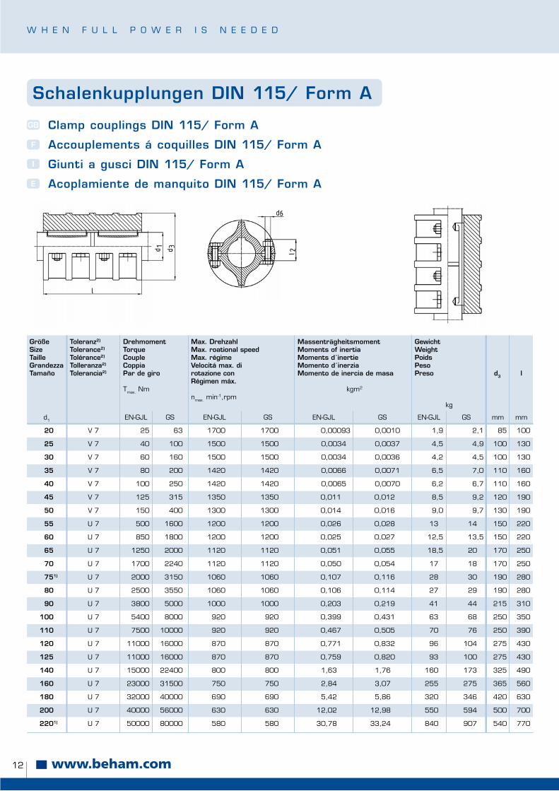
Schalenkupplungen DIN 115/ Form A
Clamp couplings DIN 115/ Form A
Accouplements á coquilles DIN 115/ Form A
Giunti a gusci DIN 115/ Form A
Acoplamiente de manquito DIN 115/ Form A
GB
F
I
E
GrößeSizeTailleGrandezzaTamaño
Toleranz2)
Tolerance2)
Tolérance2)
Tolleranza2)
Tolerancia2)
DrehmomentTorqueCoupleCoppia Par de giro
Tmax. Nm
Max. DrehzahlMax. roational speedMax. régimeVelocitá max. di rotazione conRégimen máx.
nmax. min-1,rpm
MassenträgheitsmomentMoments of inertiaMoments d´inertieMomento d´inerziaMomento de inercia de masa
kgm2
GewichtWeightPoidsPesoPreso
kg
d3 l
d1 EN-GJL GS EN-GJL GS EN-GJL GS EN-GJL GS mm mm
20 V 7 25 63 1700 1700 0,00093 0,0010 1,9 2,1 85 100
25 V 7 40 100 1500 1500 0,0034 0,0037 4,5 4,9 100 130
30 V 7 60 160 1500 1500 0,0034 0,0036 4,2 4,5 100 130
35 V 7 80 200 1420 1420 0,0066 0,0071 6,5 7,0 110 160
40 V 7 100 250 1420 1420 0,0065 0,0070 6,2 6,7 110 160
45 V 7 125 315 1350 1350 0,011 0,012 8,5 9,2 120 190
50 V 7 150 400 1300 1300 0,014 0,016 9,0 9,7 130 190
55 U 7 500 1600 1200 1200 0,026 0,028 13 14 150 220
60 U 7 850 1800 1200 1200 0,025 0,027 12,5 13,5 150 220
65 U 7 1250 2000 1120 1120 0,051 0,055 18,5 20 170 250
70 U 7 1700 2240 1120 1120 0,050 0,054 17 18 170 250
751) U 7 2000 3150 1060 1060 0,107 0,116 28 30 190 280
80 U 7 2500 3550 1060 1060 0,106 0,114 27 29 190 280
90 U 7 3800 5000 1000 1000 0,203 0,219 41 44 215 310
100 U 7 5400 8000 920 920 0,399 0,431 63 68 250 350
110 U 7 7500 10000 920 920 0,467 0,505 70 76 250 390
120 U 7 11000 16000 870 870 0,771 0,832 96 104 275 430
125 U 7 11000 16000 870 870 0,759 0,820 93 100 275 430
140 U 7 15000 22400 800 800 1,63 1,76 160 173 325 490
160 U 7 23000 31500 750 750 2,84 3,07 255 275 365 560
180 U 7 32000 40000 690 690 5,42 5,86 320 346 420 630
200 U 7 40000 56000 630 630 12,02 12,98 550 594 500 700
2201) U 7 50000 80000 580 580 30,78 33,24 840 907 540 770
13
1) Nicht in DIN 115 enthalten2) Bohrungstoleranzfeld für Wellentoleranz ISO h9
1) Not included in DIN 115
2) Hole tolerance f ield for shaf t tolerance ISO h9
D F
GB I
E1) Pas inclus dans DIN 1152) Zone de tolérance d‘alésage pour
tolérance d‘abre ISO h9
1) Non compreso nella DIN 1152) Campo di tolleranza del foro per
tolleranza albero ISO h9
1) No contenidos en DIN 1152) Campo de tolerancia de perforación
para tolerancia de ejes ISO h9
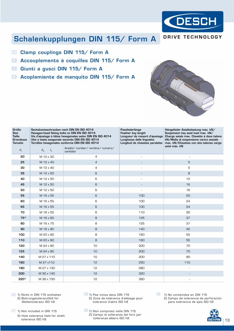
GrößeSizeTailleGrandezzaTamaño
Sechskantsschrauben nach DIN EN ISO 4014Hexagon-head fitting bolts to DIN EN ISO 4014 Vis d‘ajustage à têtes hexagonales selon DIN EN ISO 4014 Vite a testa esagonale secondo DIN EN ISO 4014Tornillos hexagonales conforme DIN EN ISO 4014
PassfederlängeFeather key lengthLongueur de ressort d‘ajustageLunghezza della linguettaLongitud de chavetas paralelas
Hängefeder Axialbelastung max. kN/Suspension key axial load max. kN/Charge axiale max. Clavette à deux talons kN/Molla di sospensione carico assiale max. kN/Chavetas con dos talones carga axial máx. kN
d1 d6 l2Anzahl/ number/ nombre/ numero/ cantidad
20 M 10 x 30 4 - -
25 M 12 x 40 4 - 5
30 M 12 x 40 4 - 5
35 M 12 x 50 6 - 8
40 M 12 x 50 6 - 12
45 M 12 x 50 6 - 16
50 M 12 x 50 6 - 16
55 M 16 x 55 6 100 20
60 M 16 x 55 6 100 24
65 M 16 x 55 6 100 24
70 M 16 x 55 6 110 30
751) M 16 x 60 8 125 37
80 M 16 x 75 8 125 37
90 M 16 x 90 8 140 42
100 M 20 x 90 8 160 55
110 M 20 x 90 8 160 55
120 M 24 x 90 10 200 70
125 M 24 x 90 10 200 70
140 M 27 x 110 10 200 90
160 M 27 x110 12 250 110
180 M 27 x 130 12 280 -
200 M 30 x 140 12 320 -
2201) M 36 x 150 12 360 -
Schalenkupplungen DIN 115/ Form A
Clamp couplings DIN 115/ Form A
Accouplements á coquilles DIN 115/ Form A
Giunti a gusci DIN 115/ Form A
Acoplamiente de manquito DIN 115/ Form A
GB
F
I
E
www.beham.com www.beham.com
W H E N F U L L P O W E R I S N E E D E D
14
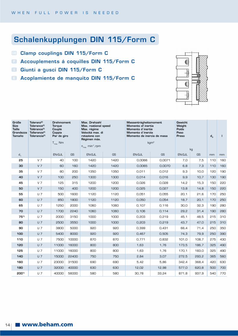
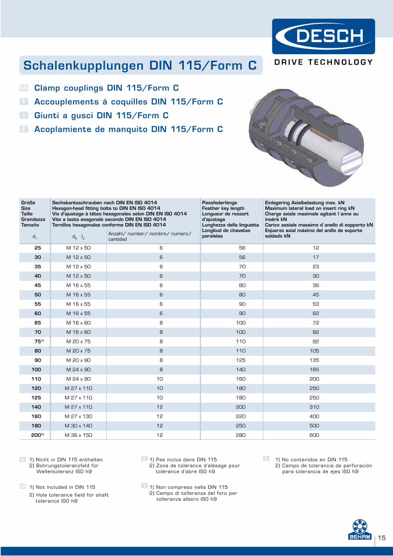
Schalenkupplungen DIN 115/Form C
Clamp couplings DIN 115/Form C
Accouplements á coquilles DIN 115/Form C
Giunti a gusci DIN 115/Form C
Acoplamiente de manquito DIN 115/Form C
GB
F
I
E
GrößeSizeTailleGrandezzaTamaño
Toleranz2)
Tolerance2)
Tolérance2)
Tolleranza2)
Tolerancia2)
DrehmomentTorqueCoupleCoppia Par de giro
Tmax. Nm
Max. DrehzahlMax. roational speedMax. régimeVelocitá max. di rotazione conRégimen máx.
nmax. min-1,rpm
MassenträgheitsmomentMoments of inertiaMoments d´inertieMomento d´inerziaMomento de inercia de masa
kgm2
GewichtWeightPoidsPesoPreso
kg
d3 l
d1 EN-GJL GS EN-GJL GS EN-GJL GS EN-GJL GS mm mm
25 V 7 40 100 1420 1420 0,0066 0,0071 7,0 7,5 110 160
30 V 7 60 160 1420 1420 0,0065 0,0070 6,8 7,3 110 160
35 V 7 80 200 1350 1350 0,011 0,012 9,3 10,0 120 190
40 V 7 100 250 1300 1300 0,014 0,016 9,9 10,7 130 190
45 V 7 125 315 1200 1200 0,026 0,028 14,2 15,3 150 220
50 V 7 150 400 1200 1200 0,025 0,027 13,8 14,8 150 220
55 U 7 500 1600 1120 1120 0,051 0,055 20,1 21,6 170 250
60 U 7 850 1800 1120 1120 0,050 0,054 18,7 20,1 170 250
65 U 7 1250 2000 1060 1060 0,107 0,116 30,0 32,3 190 280
70 U 7 1700 2240 1060 1060 0,106 0,114 29,2 31,4 190 280
751) U 7 2000 3150 1000 1000 0,203 0,219 45,1 48,5 215 310
80 U 7 2500 3550 1000 1000 0,203 0,219 43,7 47,0 215 310
90 U 7 3800 5000 920 920 0,399 0,431 66,4 71,4 250 350
100 U 7 5400 8000 920 920 0,467 0,505 74,3 79,9 250 390
110 U 7 7500 10000 870 870 0,771 0,832 101,0 108,7 275 430
120 U 7 11000 16000 800 800 1,63 1,76 173,5 186,7 325 490
125 U 7 11000 16000 800 800 1,63 1,76 170,1 183,0 325 490
140 U 7 15000 22400 750 750 2,84 3,07 272,5 293,2 365 560
160 U 7 23000 31500 690 690 5,42 5,86 342,4 368,4 420 630
180 U 7 32000 40000 630 630 12,02 12,98 577,0 620,8 500 700
2001) U 7 40000 56000 580 580 30,78 33,24 871,8 937,9 540 770
15
GrößeSizeTailleGrandezzaTamaño
Sechskantsschrauben nach DIN EN ISO 4014Hexagon-head fitting bolts to DIN EN ISO 4014 Vis d‘ajustage à têtes hexagonales selon DIN EN ISO 4014 Vite a testa esagonale secondo DIN EN ISO 4014Tornillos hexagonales conforme DIN EN ISO 4014
PassfederlängeFeather key lengthLongueur de ressort d‘ajustageLunghezza della linguettaLongitud de chavetas paralelas
Einlegering Axialbelastung max. kNMaximum lateral load on insert ring kNCharge axiale maximale agitant l´anne au inséré kNCarico assiale massimo d´anello di sopporto kNEsjuerzo axial máximo del anillo de soporte soldado kNd1 d6 l2
Anzahl/ number/ nombre/ numero/ cantidad
25 M 12 x 50 6 56 12
30 M 12 x 50 6 56 17
35 M 12 x 50 6 70 23
40 M 12 x 50 6 70 30
45 M 16 x 55 6 80 36
50 M 16 x 55 6 80 45
55 M 16 x 55 6 90 53
60 M 16 x 55 6 90 62
65 M 16 x 60 8 100 72
70 M 16 x 60 8 100 82
751) M 20 x 75 8 110 92
80 M 20 x 75 8 110 105
90 M 20 x 90 8 125 135
100 M 24 x 90 8 140 165
110 M 24 x 90 10 160 200
120 M 27 x 110 10 180 250
125 M 27 x 110 10 180 250
140 M 27 x 110 12 200 310
160 M 27 x 130 12 220 400
180 M 30 x 140 12 250 500
2001) M 36 x 150 12 280 600
1) Nicht in DIN 115 enthalten2) Bohrungstoleranzfeld für Wellentoleranz ISO h9
1) Not included in DIN 115
2) Hole tolerance f ield for shaf t tolerance ISO h9
D F
GB I
E1) Pas inclus dans DIN 1152) Zone de tolérance d‘alésage pour
tolérance d‘abre ISO h9
1) Non compreso nella DIN 1152) Campo di tolleranza del foro per
tolleranza albero ISO h9
1) No contenidos en DIN 1152) Campo de tolerancia de perforación
para tolerancia de ejes ISO h9
Schalenkupplungen DIN 115/Form C
Clamp couplings DIN 115/Form C
Accouplements á coquilles DIN 115/Form C
Giunti a gusci DIN 115/Form C
Acoplamiente de manquito DIN 115/Form C
GB
F
I
E

www.beham.com www.beham.com
W H E N F U L L P O W E R I S N E E D E D
16
ww
w.d
esch
.deDESCH Drive Technology
Postbox 14 40D-59753 Arnsberg/GermanyKleinbahnstraße 21D-59759 Arnsberg/GermanyTelephone +49 (0) 29 32 - 3 00 - 0 Fax +49 (0) 29 32 - 3 00 - 899Internet www.desch.deE-mail [email protected]
DESCH Drive TechnologyLimited Partnership240 Shearson Crescent Cambridge, OntarioCanada N 1T 1J6Telephone +1800 - 2 63 18 66
+1519 - 6 21 45 60Fax +1519 - 6 23 11 69Internet www.desch.on.caE-mail [email protected]
Telefon-Anschlüsse im Stammhaus Arnsberg/ Telephone numbers of our head office in Arnsberg/Numéros de téléphone de notre siège Arnsberg/ Numeri di telefono della nostra sede di Arnsberg/Números de teléfono en la central en Arnsberg
Phone FaxDES DESCH Engineering Service +49 (0) 29 32 300 - 200 300 - 811DPC DESCH Power Transmission Center +49 (0) 29 32 300 - 103 300 - 830DCT DESCH Clutch Technology +49 (0) 29 32 300 - 170 300 - 50DGP DESCH Gearbox and Press Drives +49 (0) 29 32 300 - 153 300 - 811
DESCH Drive TechnologyUfficio di rappresentanza in ItaliaVia Cavriana, 3I-20134 MilanoTelephone +3902 - 7 39 12 80Fax +3902 - 7 39 12 81Internet www.desch.deE-mail [email protected]
DESCH ist MitgliedDESCH is a member ofDESCH est membre deDESCH è membroDESCH es un miembro
LieferprogrammSchaltbare KupplungenElastische KupplungenDrehstarre KupplungenPressenantriebeGleitlagerRiementriebePlaneten und SondergetriebeKomplette Antriebslösungen
D
GB
F
I E
Programme de LivraisonAccouplements commutablesAccouplements élastiquesAccouplements rigidesEntraînements de pressesPaliers lissesEngrenages planétaires et spéciauxEngrenages complètes
Delivery ProgrammeClutchesFlexible couplingsRigid couplingsPress drivesPlain bearingsBelt drivesPlanetary gears and special gearsComplete drive solutions
Programma di VenditaFrizioniGiunti elasticiGiunti rigidi Azionamenti per PresseSopporti con bronzinaTrasmissioni a cinghiaRiduttori epicicloidali e specialiSoluzioni e azionamenti completi
Gama de SuministroAcoplamientos conmutablesAcoplamientos elásticosAcoplamientos rígidosTransmisiones de prensasCojinetes de deslizamientoMecanismos de correaEngranajes planetarios y especialesSoluciones de transmisión integrales
Technische Änderungen vorbehalten Technical changes reservedSous réserve de modif ications techniquesCi riserviamo eventuali modif iche tecnicheReservado el derecho a realizar modif icaciones técnicas © DESCH Antriebstechnik GmbH & Co. KG · SK 07
© DESCH Antriebstechnik GmbH & Co. KG · HW 07
Technische Änderungen vorbehalten Technical changes reservedSous réserve de modif ications techniquesCi riserviamo eventuali modif iche tecnicheReservado el derecho a realizar modif icaciones técnicas
www.desch.de
www.beham.com
BEHAM Techn. Handels GmbHA-4910 RIED . Bahnhofstraße 67 | [email protected].: +43 / (0) 7752 / 879 31 - 0 | Fax: +43 / (0) 7752 / 879 31 - 1022
A-1230 WIEN . Perfektastraße 38 | [email protected].: +43 / (0) 1 /667 06 01 - 0 | Fax: +43 / (0) 1 /667 06 01 - 5022
Die technischen Angaben in diesem Katalog stellen allgemeine, nicht verbindliche Richtwerte dar, welche auf Jahrzehnte langer Forschung und Entwicklung unserer Herstellerpartner beruhen. Die Angaben in diesem Katalog sind sorgfältig zusam-mengestellt worden. Trotzdem können wir Satz- bzw. Druckfehler nicht ausschließen. Da immer wieder einzelne Bauformen aus dem Fertigungsprogramm unserer Hersteller gestrichen werden, können wir auch keine Liefergarantie für die angeführ-ten Dimensionen und Bauformen übernehmen.
DESCH Drive Technology Postbox 14 40D-59753 Arnsberg/GermanyKleinbahnstraße 21D-59759 Arnsberg/Germany


![Inhaltsverzeichnis · [ I ] SAE-Flansche (ISO 6162) / SAE-flanges (ISO 6162) Seite / Page SAE-Flanschhälften / SAE-split flange halves FH-... 1 SAE-Vollflansch / SAE-flange](https://img.pdfslide.org/doc/110x75/5b1675127f8b9a546d8c0fe1/inhaltsverzeichnis-i-sae-flansche-iso-6162-sae-flanges-iso-6162-seite.jpg)