Embed Size (px)
Citation preview
Auslegung & Optimierung von mehrstufigen Getrieben
Dr.-Ing. Tobias Schulze – DriveConcepts GmbH, Dresden
Design and optimization of planetary gears under consideration of all relevant influences
Prof. Dr.-Ing. Berthold Schlecht, TU Dresden Dr.-Ing. Tobias Schulze, DriveConcepts GmbH Dresden
Dipl.-Ing. Christian Hartmann-Gerlach, DriveConcepts GmbH Dresden
Abstract
The calculation of gears especially planetary gears can just be carried out by the
consideration of influences of the whole drive train and the analysis of all relevant machine
elements. In this case the gear is more than the sum of its machine elements. Relevant
interactions need to be considered under real conditions. The standardized calculations are
for the safe dimensioning of the machine elements with the consideration of realistic load
assumptions decisive. But they need to be completed by extended analysis of load
distribution, flank pressure, root stress, transmission error and contact temperature, /1,2,4/.
Gear design process
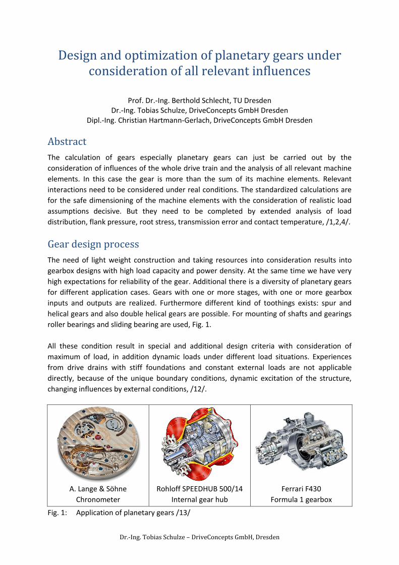
The need of light weight construction and taking resources into consideration results into
gearbox designs with high load capacity and power density. At the same time we have very
high expectations for reliability of the gear. Additional there is a diversity of planetary gears
for different application cases. Gears with one or more stages, with one or more gearbox
inputs and outputs are realized. Furthermore different kind of toothings exists: spur and
helical gears and also double helical gears are possible. For mounting of shafts and gearings
roller bearings and sliding bearing are used, Fig. 1.
All these condition result in special and additional design criteria with consideration of
maximum of load, in addition dynamic loads under different load situations. Experiences
from drive drains with stiff foundations and constant external loads are not applicable
directly, because of the unique boundary conditions, dynamic excitation of the structure,
changing influences by external conditions, /12/.
A. Lange & Söhne
Chronometer
Rohloff SPEEDHUB 500/14
Internal gear hub
Ferrari F430
Formula 1 gearbox
Fig. 1: Application of planetary gears /13/
Auslegung & Optimierung von mehrstufigen Getrieben
Dr.-Ing. Tobias Schulze – DriveConcepts GmbH, Dresden
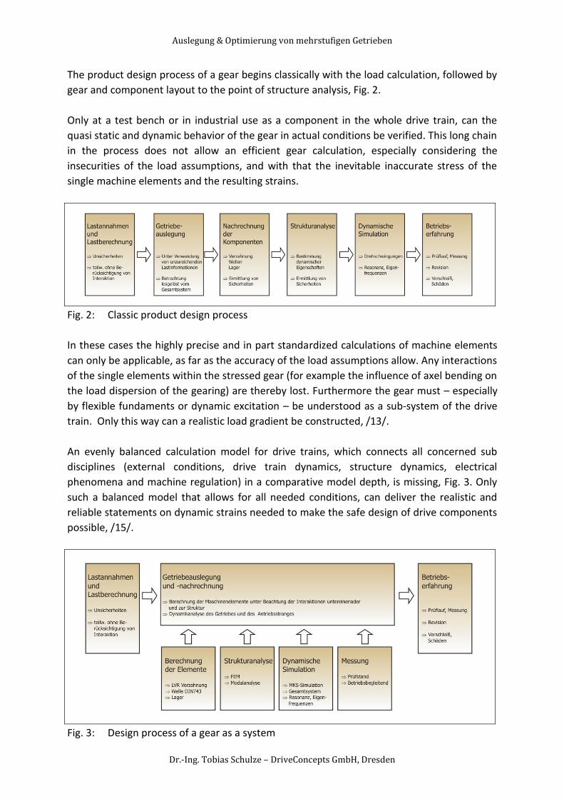
The product design process of a gear begins classically with the load calculation, followed by
gear and component layout to the point of structure analysis, Fig. 2.
Only at a test bench or in industrial use as a component in the whole drive train, can the
quasi static and dynamic behavior of the gear in actual conditions be verified. This long chain
in the process does not allow an efficient gear calculation, especially considering the
insecurities of the load assumptions, and with that the inevitable inaccurate stress of the
single machine elements and the resulting strains.
Fig. 2: Classic product design process
In these cases the highly precise and in part standardized calculations of machine elements
can only be applicable, as far as the accuracy of the load assumptions allow. Any interactions
of the single elements within the stressed gear (for example the influence of axel bending on
the load dispersion of the gearing) are thereby lost. Furthermore the gear must – especially
by flexible fundaments or dynamic excitation – be understood as a sub-system of the drive
train. Only this way can a realistic load gradient be constructed, /13/.
An evenly balanced calculation model for drive trains, which connects all concerned sub
disciplines (external conditions, drive train dynamics, structure dynamics, electrical
phenomena and machine regulation) in a comparative model depth, is missing, Fig. 3. Only
such a balanced model that allows for all needed conditions, can deliver the realistic and
reliable statements on dynamic strains needed to make the safe design of drive components
possible, /15/.
Fig. 3: Design process of a gear as a system
Auslegung & Optimierung von mehrstufigen Getrieben
Dr.-Ing. Tobias Schulze – DriveConcepts GmbH, Dresden
The resulting problems and damages can not only be explained through analysis of the single
modules. In fact the essential influences of the surrounding system components must be
accounted for and included in the computation. Here arises the real difficulty of finding the
necessary system parameters to solve the respective question.
That is why the product development process of the future is moving more and more to
system analysis, instead of the design of single machine elements. Decisive in gear
development is the continuous – mostly software supported – analysis, result conditioning
and data maintenance to the point of supervision of the life cycle of a gear. On the one side
all calculations of the machine elements gear, axle, bearing, axle-hub connection, screw
connection etc. are to be implemented following the current standards. These must be
supplemented through detailed examination of load gradients, load distribution, to the point
of optimization of single target parameters (mass, stiffness, ..)
Gearbox development and calculation according standards
Especially for design concepts of planetary and spur gearboxes the newest development of
DriveConcepts GmbH - the product MDESIGN® gearbox - is established. This calculation
software gives complete product information in the early phase of product life cycle (PLC).
The calculation can’t replace measurements and test drives, but iteration steps can be
reduced economically. The software allows an intuitive and easy handling in the design
process of whole gearboxes from the dimensioning of the machine elements – shafts,
bearings and toothings - according to the actual standards, /5,6,7/.
For toothing are implemented:
- DIN 3990:1987 T1-T6
- ISO 6336:2008 T1-T3, T5 & TechnicalCorrigendum1:2008
Future work for toothings:
- micro pitting according to ISO/TR 15144-1
- scuffing according to ISO/TR 13989 1 & 2, AGMA 925
- gear mesh efficiency / loss factor HV & HVL
The shafts of the gearbox are calculated according to:
- DIN 743:2008 T1-T4 & Beiblatt 1,2
For the roller bearings are different calculations possible:
- life time LH10 according DIN ISO 281:2009
- modified life time according DIN ISO 281:2009 Beiblatt 1,3
- advanced modified life time according DIN ISO 281:2009 Beiblatt 1,3
- life time according ISO/TR 16281:2009
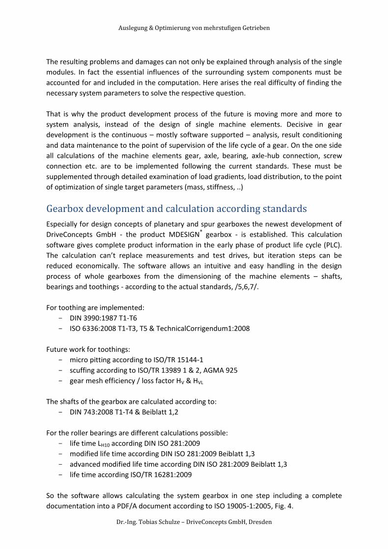
So the software allows calculating the system gearbox in one step including a complete
documentation into a PDF/A document according to ISO 19005-1:2005, Fig. 4.
Auslegung & Optimierung von mehrstufigen Getrieben
Dr.-Ing. Tobias Schulze – DriveConcepts GmbH, Dresden
Fig. 4: User interface of MDESIGN® gearbox with 3D-GearDesigner® and result page /10/
Gear optimization (macro geometry)
The following chapter shows the gear optimization at some case studies:
Load distribution
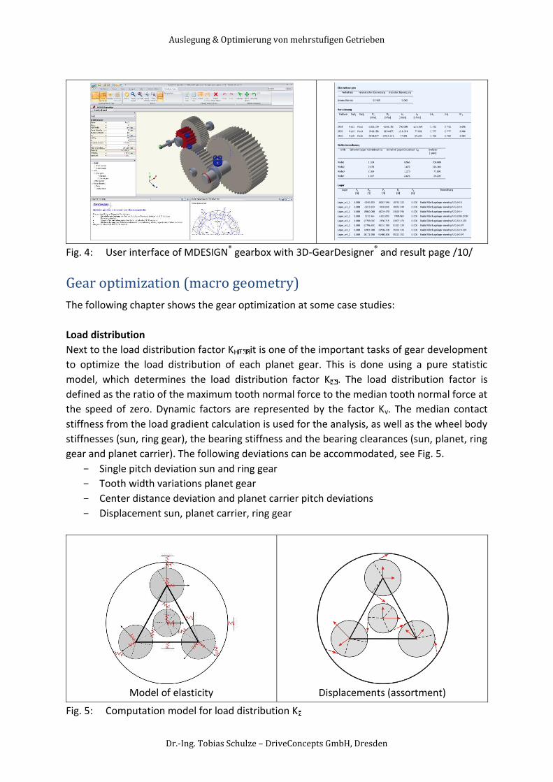
Next to the load distribution factor KH it is one of the important tasks of gear development
to optimize the load distribution of each planet gear. This is done using a pure statistic
model, which determines the load distribution factor K . The load distribution factor is
defined as the ratio of the maximum tooth normal force to the median tooth normal force at
the speed of zero. Dynamic factors are represented by the factor Kv. The median contact
stiffness from the load gradient calculation is used for the analysis, as well as the wheel body
stiffnesses (sun, ring gear), the bearing stiffness and the bearing clearances (sun, planet, ring
gear and planet carrier). The following deviations can be accommodated, see Fig. 5.
- Single pitch deviation sun and ring gear
- Tooth width variations planet gear
- Center distance deviation and planet carrier pitch deviations
- Displacement sun, planet carrier, ring gear
Model of elasticity
Displacements (assortment)
Fig. 5: Computation model for load distribution K
Auslegung & Optimierung von mehrstufigen Getrieben
Dr.-Ing. Tobias Schulze – DriveConcepts GmbH, Dresden
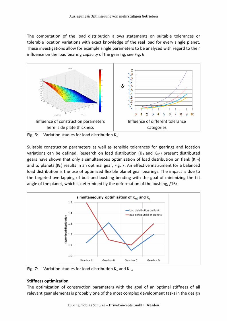
The computation of the load distribution allows statements on suitable tolerances or
tolerable location variations with exact knowledge of the real load for every single planet.
These investigations allow for example single parameters to be analyzed with regard to their
influence on the load bearing capacity of the gearing, see Fig. 6.
Influence of construction parameters
here: side plate thickness
Influence of different tolerance
categories
Fig. 6: Variation studies for load distribution K
Suitable construction parameters as well as sensible tolerances for gearings and location
variations can be defined. Research on load distribution (K and K ) present distributed
gears have shown that only a simultaneous optimization of load distribution on flank (K )
and to planets (K ) results in an optimal gear, Fig. 7. An effective instrument for a balanced
load distribution is the use of optimized flexible planet gear bearings. The impact is due to
the targeted overlapping of bolt and bushing bending with the goal of minimizing the tilt
angle of the planet, which is determined by the deformation of the bushing, /16/.
Fig. 7: Variation studies for load distribution K and K
Stiffness optimization
The optimization of construction parameters with the goal of an optimal stiffness of all
relevant gear elements is probably one of the most complex development tasks in the design
Auslegung & Optimierung von mehrstufigen Getrieben
Dr.-Ing. Tobias Schulze – DriveConcepts GmbH, Dresden
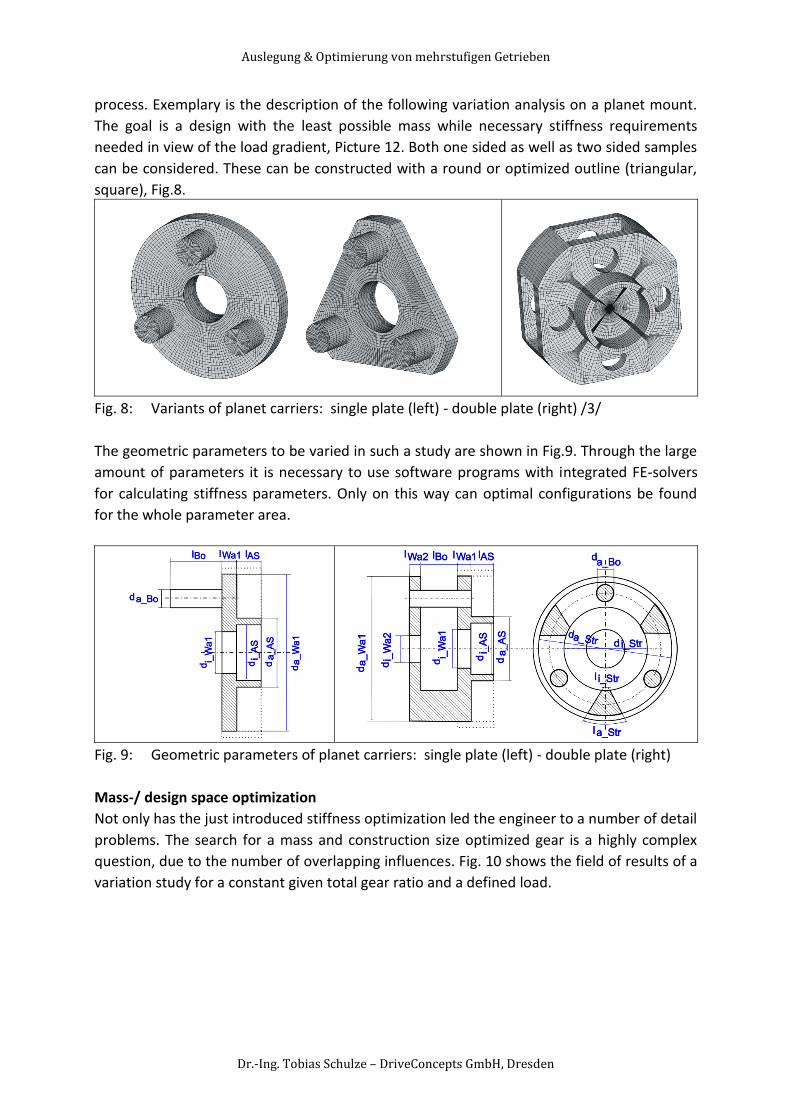
process. Exemplary is the description of the following variation analysis on a planet mount.
The goal is a design with the least possible mass while necessary stiffness requirements
needed in view of the load gradient, Picture 12. Both one sided as well as two sided samples
can be considered. These can be constructed with a round or optimized outline (triangular,
square), Fig.8.
Fig. 8: Variants of planet carriers: single plate (left) - double plate (right) /3/
The geometric parameters to be varied in such a study are shown in Fig.9. Through the large
amount of parameters it is necessary to use software programs with integrated FE-solvers
for calculating stiffness parameters. Only on this way can optimal configurations be found
for the whole parameter area.
Fig. 9: Geometric parameters of planet carriers: single plate (left) - double plate (right)
Mass-/ design space optimization
Not only has the just introduced stiffness optimization led the engineer to a number of detail
problems. The search for a mass and construction size optimized gear is a highly complex
question, due to the number of overlapping influences. Fig. 10 shows the field of results of a
variation study for a constant given total gear ratio and a defined load.
Auslegung & Optimierung von mehrstufigen Getrieben
Dr.-Ing. Tobias Schulze – DriveConcepts GmbH, Dresden
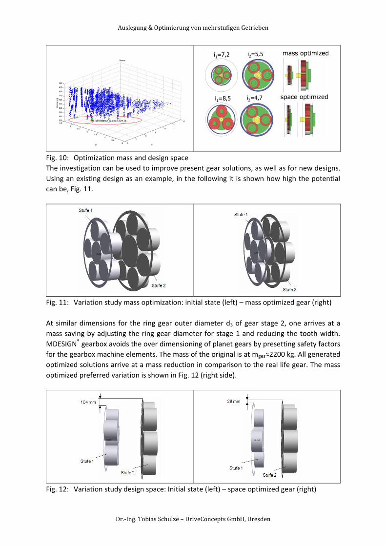
Fig. 10: Optimization mass and design space
The investigation can be used to improve present gear solutions, as well as for new designs.
Using an existing design as an example, in the following it is shown how high the potential
can be, Fig. 11.
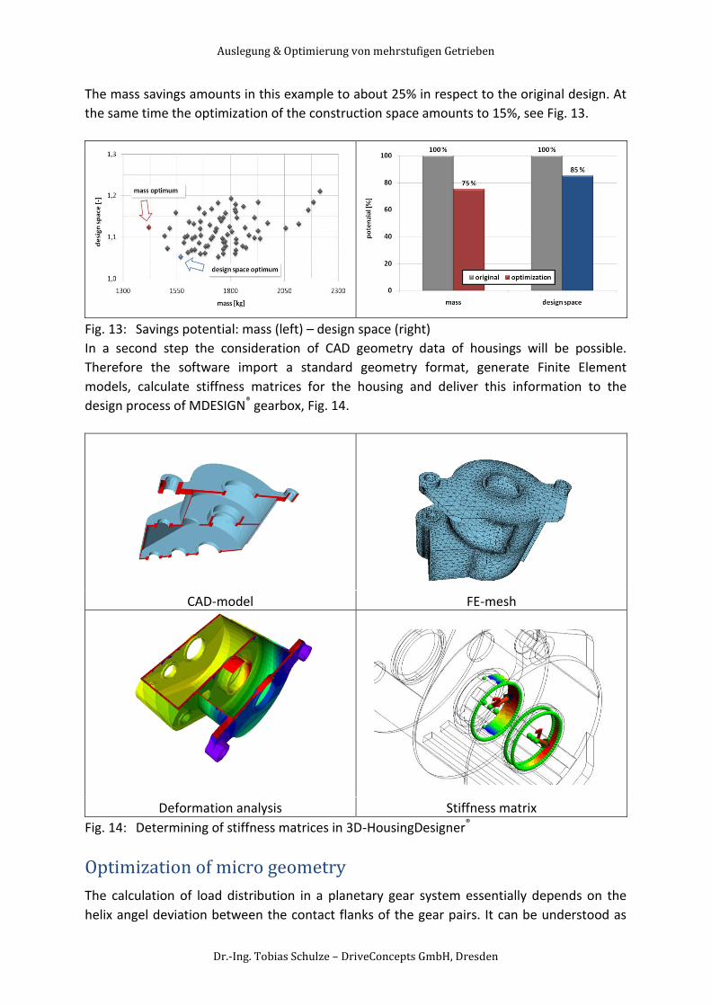
Fig. 11: Variation study mass optimization: initial state (left) – mass optimized gear (right)
At similar dimensions for the ring gear outer diameter d3 of gear stage 2, one arrives at a
mass saving by adjusting the ring gear diameter for stage 1 and reducing the tooth width.
MDESIGN® gearbox avoids the over dimensioning of planet gears by presetting safety factors
for the gearbox machine elements. The mass of the original is at mges≈2200 kg. All generated
optimized solutions arrive at a mass reduction in comparison to the real life gear. The mass
optimized preferred variation is shown in Fig. 12 (right side).
Fig. 12: Variation study design space: Initial state (left) – space optimized gear (right)
Auslegung & Optimierung von mehrstufigen Getrieben
Dr.-Ing. Tobias Schulze – DriveConcepts GmbH, Dresden
The mass savings amounts in this example to about 25% in respect to the original design. At
the same time the optimization of the construction space amounts to 15%, see Fig. 13.
Fig. 13: Savings potential: mass (left) – design space (right)
In a second step the consideration of CAD geometry data of housings will be possible.
Therefore the software import a standard geometry format, generate Finite Element
models, calculate stiffness matrices for the housing and deliver this information to the
design process of MDESIGN® gearbox, Fig. 14.
CAD-model FE-mesh
Deformation analysis Stiffness matrix
Fig. 14: Determining of stiffness matrices in 3D-HousingDesigner®
Optimization of micro geometry
The calculation of load distribution in a planetary gear system essentially depends on the
helix angel deviation between the contact flanks of the gear pairs. It can be understood as
Auslegung & Optimierung von mehrstufigen Getrieben
Dr.-Ing. Tobias Schulze – DriveConcepts GmbH, Dresden
the sum of different influences. It is assumed that the effects are overlying independently,
the sum of contact line deviation can be calculated with the single deviations, /11/.
The calculation of single displacements and deformations of all gear box bodies – especially
the planet carrier, the coupling of ring gear and gear wheel bodies and the deformation of
teeth – is in planetary gearboxes more complex than in spur gearboxes. To determine the
load distribution the flank deviation for the tooth contact sun/planet and the tooth contact
planet/ring gear is calculated by the new software MDESIGN® LVRplanet, /8,9/.
The result of the calculation is the excessive of the line load, which is expressed by the factor
KHß. In general the excessive of the line load is on the flank side opposite to the deviated
flank side.
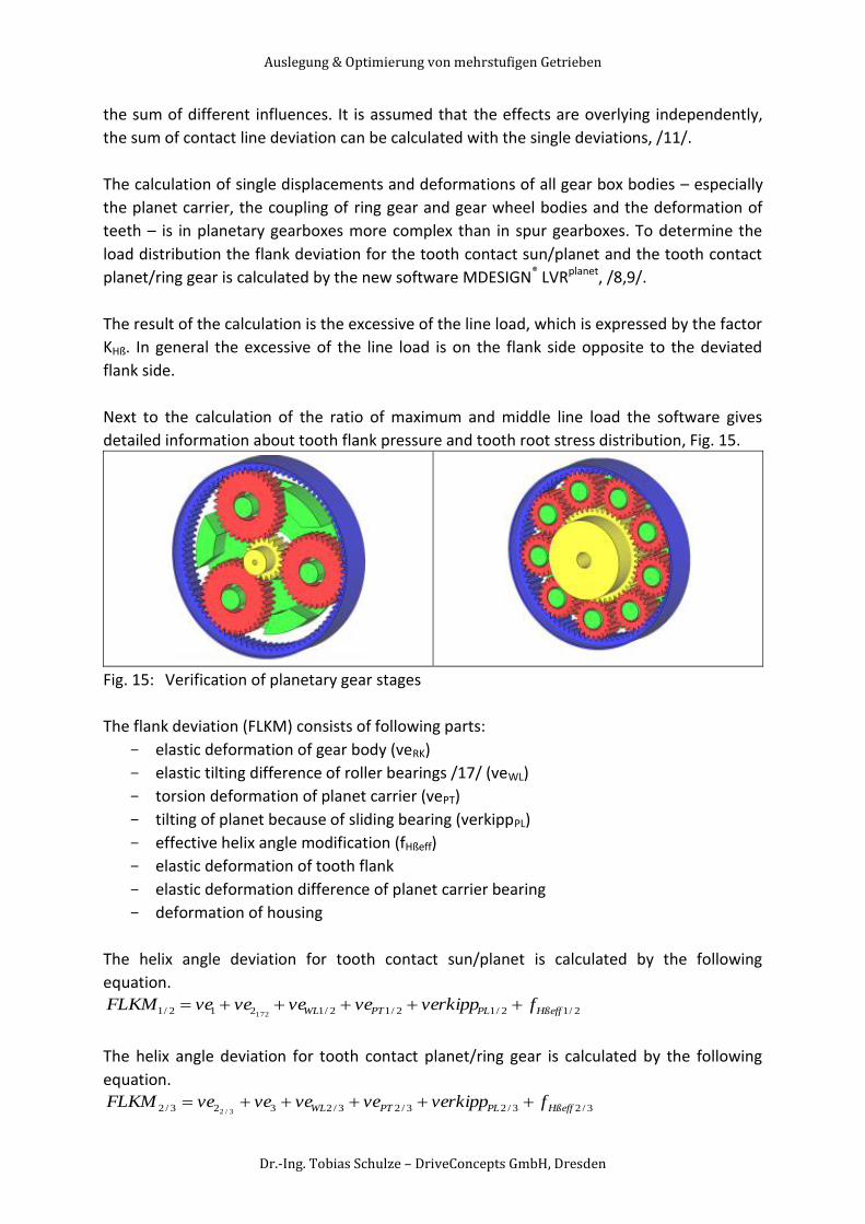
Next to the calculation of the ratio of maximum and middle line load the software gives
detailed information about tooth flank pressure and tooth root stress distribution, Fig. 15.
Fig. 15: Verification of planetary gear stages
The flank deviation (FLKM) consists of following parts:
- elastic deformation of gear body (veRK)
- elastic tilting difference of roller bearings /17/ (veWL)
- torsion deformation of planet carrier (vePT)
- tilting of planet because of sliding bearing (verkippPL)
- effective helix angle modification (fHßeff)
- elastic deformation of tooth flank
- elastic deformation difference of planet carrier bearing
- deformation of housing
The helix angle deviation for tooth contact sun/planet is calculated by the following
equation.
2/12/12/12/1212/1 172 HßeffPLPTWL fverkippveveveveFLKM
The helix angle deviation for tooth contact planet/ring gear is calculated by the following
equation.
3/23/23/23/2323/2 3/2 HßeffPLPTWL fverkippveveveveFLKM
Auslegung & Optimierung von mehrstufigen Getrieben
Dr.-Ing. Tobias Schulze – DriveConcepts GmbH, Dresden
- ve1: deformation difference of sun
- ve2: deformation difference of planet
- ve3: deformation difference of ring gear
The deformation is calculated by the FE-method and afterwards it is added to the flank
deviation. All parts of the helix angle deviation have to be added as values normal to the
flank. The database of the calculation is saved in XML-Format. With this a structured
depositing of design-, modifications-, deviation-, load- and control data is possible.
Furthermore the program has a project management which is based on a database to save
projects, for standard examples and more calculation guidelines, /14/.
After input of all necessary parameters all data are checked, the design models are
generated and the FE-models for the gears with coupling design and the planet carrier are
created. For an efficient calculation it is necessary and reasonable to use software.
DriveConcepts GmbH develops software solutions for drive technology, which is
characterized by clear and intuitive handling of all data. In the background academic
established calculation kernels and consistent structured interfaces help to solve the actual
task efficiently.
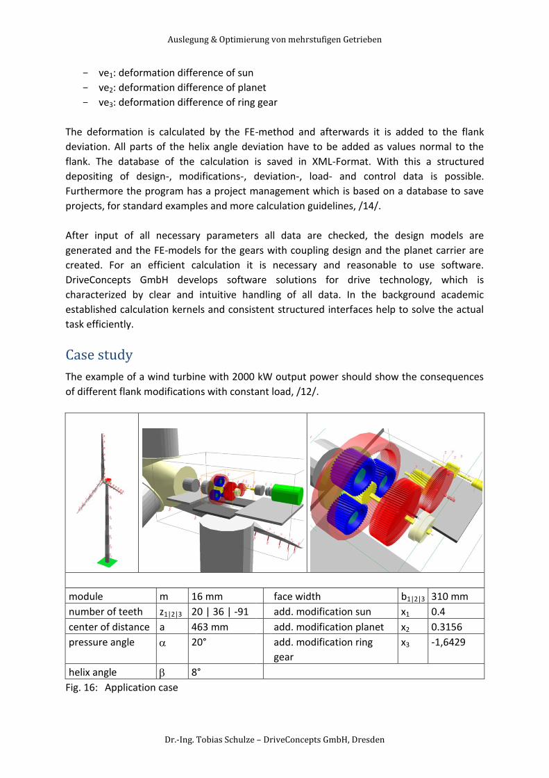
Case study
The example of a wind turbine with 2000 kW output power should show the consequences
of different flank modifications with constant load, /12/.
module m 16 mm face width b1|2|3 310 mm
number of teeth z1|2|3 20 | 36 | -91 add. modification sun x1 0.4
center of distance a 463 mm add. modification planet x2 0.3156
pressure angle 20° add. modification ring
gear
x3 -1,6429
helix angle 8°
Fig. 16: Application case
Auslegung & Optimierung von mehrstufigen Getrieben
Dr.-Ing. Tobias Schulze – DriveConcepts GmbH, Dresden
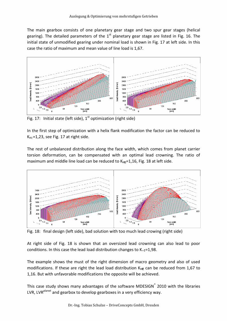
The main gearbox consists of one planetary gear stage and two spur gear stages (helical
gearing). The detailed parameters of the 1st planetary gear stage are listed in Fig. 16. The
initial state of unmodified gearing under nominal load is shown in Fig. 17 at left side. In this
case the ratio of maximum and mean value of line load is 1,67.
Fig. 17: Initial state (left side), 1st optimization (right side)
In the first step of optimization with a helix flank modification the factor can be reduced to
KH =1,23, see Fig. 17 at right side.
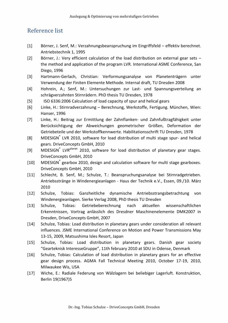
The rest of unbalanced distribution along the face width, which comes from planet carrier
torsion deformation, can be compensated with an optimal lead crowning. The ratio of
maximum and middle line load can be reduced to K =1,16, Fig. 18 at left side.
Fig. 18: final design (left side), bad solution with too much lead crowing (right side)
At right side of Fig. 18 is shown that an oversized lead crowning can also lead to poor
conditions. In this case the lead load distribution changes to K =1,98.
The example shows the must of the right dimension of macro geometry and also of used
modifications. If these are right the lead load distribution K can be reduced from 1,67 to
1,16. But with unfavorable modifications the opposite will be achieved.
This case study shows many advantages of the software MDESIGN® 2010 with the libraries
LVR, LVRplanet and gearbox to develop gearboxes in a very efficiency way.
Auslegung & Optimierung von mehrstufigen Getrieben
Dr.-Ing. Tobias Schulze – DriveConcepts GmbH, Dresden
Reference list
[1] Börner, J. Senf, M.: Verzahnungsbeanspruchung im Eingriffsfeld – effektiv berechnet.
Antriebstechnik 1, 1995
[2] Börner, J.: Very efficient calculation of the load distribution on external gear sets –
the method and application of the program LVR. International ASME Conference, San
Diego, 1996
[3] Hartmann-Gerlach, Christian: Verformungsanalyse von Planetenträgern unter
Verwendung der Finiten Elemente Methode. Internal draft, TU Dresden 2008
[4] Hohrein, A.; Senf, M.: Untersuchungen zur Last- und Spannungsverteilung an
schrägverzahnten Stirnrädern. PhD thesis TU Dresden, 1978
[5] ISO 6336:2006 Calculation of load capacity of spur and helical gears
[6] Linke, H.: Stirnradverzahnung – Berechnung, Werkstoffe, Fertigung. München, Wien:
Hanser, 1996
[7] Linke, H.: Beitrag zur Ermittlung der Zahnflanken- und Zahnfußtragfähigkeit unter
Berücksichtigung der Abweichungen geometrischer Größen, Deformation der
Getriebeteile und der Werkstoffkennwerte. Habilitationsschrift TU Dresden, 1978
[8] MDESIGN® LVR 2010, software for load distribution of multi stage spur- and helical
gears. DriveConcepts GmbH, 2010
[9] MDESIGN® LVRplanet 2010, software for load distribution of planetary gear stages.
DriveConcepts GmbH, 2010
[10] MDESIGN® gearbox 2010, design and calculation software for multi stage gearboxes.
DriveConcepts GmbH, 2010
[11] Schlecht, B. Senf, M.; Schulze, T.: Beanspruchungsanalyse bei Stirnradgetrieben.
Antriebsstränge in Windenergieanlagen - Haus der Technik e.V., Essen, 09./10. März
2010
[12] Schulze, Tobias: Ganzheitliche dynamische Antriebsstrangsbetrachtung von
Windenergieanlagen. Sierke Verlag 2008, PhD thesis TU Dresden
[13] Schulze, Tobias: Getriebeberechnung nach aktuellen wissenschaftlichen
Erkenntnissen, Vortrag anlässlich des Dresdner Maschinenelemente DMK2007 in
Dresden, DriveConcepts GmbH, 2007
[14] Schulze, Tobias: Load distribution in planetary gears under consideration all relevant
influences. JSME International Conference on Motion and Power Transmissions May
13-15, 2009, Matsushima Isles Resort, Japan
[15] Schulze, Tobias: Load distribution in planetary gears. Danish gear society
“Gearteknisk InteresseGruppe”, 11th february 2010 at SDU in Odense, Denmark
[16] Schulze, Tobias: Calculation of load distribution in planetary gears for an effective
gear design process. AGMA Fall Technical Meeting 2010, October 17-19, 2010,
Milwaukee Wis, USA
[17] Wiche, E.: Radiale Federung von Wälzlagern bei beliebiger Lagerluft. Konstruktion,
Berlin 19(1967)5