Embed Size (px)
Citation preview
© by Physik Instrumente (PI) Vorlage FM 7.3-15 A1 Pflichtenheft Page 1 of 39
Physik Instrumente (PI ) GmbH & Co. KG - Auf der Römerstraße 1 - 76228 Karlsruhe/Germany Phone +49 721 / 48 46 - 0 Fax +49 721 / 48 46 - 100 email: [email protected]
Design Study/Requirement Specification
.
Kostenträger / Project No.:
M-900K155
Titel: M2 Positioning System
Autor / Author: Karin Hernandez Mozos (KHe)
Version: 01.001
Datum / Date: 12.06.2007
Dokumenten-Nr. / Document No.: DOC-000028980
Status: 2. Revision
All information provided in this document is to be considered confidential, proprietary and secret information. It is intended only for the use of the individual or entity to whom it is sent. Individual or entity agrees to not disseminate or copy this information to anyone other than originally specified without the written consent of PHYSIK INSTRUMENTE GmbH & Co.

Proposal Title: A-900K548
ProposalDoc.-Nr. DOC-000028980 Version 01.001 Date 12.06.2007 © by Physik Instrumente (PI) Vorlage FM 7.3-15 A1 Pflichtenheft Page 2 of 39
Physik Instrumente (PI ) GmbH & Co. KG - Auf der Römerstraße 1 - 76228 Karlsruhe/Germany Phone +49 721 / 48 46 - 0 Fax +49 721 / 48 46 - 100 email: [email protected]
Authors Name Part(s) of the requirement specification Karin Hernandez Mozos (KHe)
Mechanics (Hexapod)
Ralf Krämer (RKr) Mechanics and specifications (Hexapod) Klaus Pollak (KPo) Mechanics (Tip/Tilt) Christoph Stiebel (STIE) Electronics (Hexapod) Christopher Mock (CMo) Electronics (Tip/Tilt) Erik Mankin (EMa) Software Matthias Schulz (MSz) Cables
Modification history
Version Modification Date Name 00.001 First Draft 02.05.07 ABo 01.000 First Revision: updated dynamic simulation for 70Hz bandwidth; simpli-
fied transfer function added; system stiffness added; force simulation up-dated; ambient conditions corrected; max. temp. change added; CoG added to dimensional drawing
30.05.07 ABo
01.001 Drawings and dimensions of electronic components added; dimensional drawing updated; comments about increased seismic stability; specifica-tions updated: MIM, repeatability of home position, motion response, ve-locity stability, max. cable length, system weight
12.06.07 ABo
Supporting regulations and standards
Nr. Title/Author Document number Version
Abbreviation / Definition
Abbreviation Description TMS Thermal Management System

Proposal Title: A-900K548
ProposalDoc.-Nr. DOC-000028980 Version 01.001 Date 12.06.2007 © by Physik Instrumente (PI) Vorlage FM 7.3-15 A1 Pflichtenheft Page 3 of 39
Physik Instrumente (PI ) GmbH & Co. KG - Auf der Römerstraße 1 - 76228 Karlsruhe/Germany Phone +49 721 / 48 46 - 0 Fax +49 721 / 48 46 - 100 email: [email protected]
Proposal Title: A-900K548
ProposalDoc.-Nr. DOC-000028980 Version 01.001 Date 12.06.2007 © by Physik Instrumente (PI) Vorlage FM 7.3-15 A1 Pflichtenheft Page 4 of 39
Physik Instrumente (PI ) GmbH & Co. KG - Auf der Römerstraße 1 - 76228 Karlsruhe/Germany Phone +49 721 / 48 46 - 0 Fax +49 721 / 48 46 - 100 email: [email protected]
Table of Contents 1 Introduction ..........................................................................................................................................5 2 System Description..............................................................................................................................5
2.1 Function Description Hexapod ....................................................................................................5 2.1.1 Mechanics...................................................................................................................................5 2.1.2 Linear Actuators..........................................................................................................................5 2.1.3 Details.........................................................................................................................................6 2.1.4 Positioning Ranges.....................................................................................................................6
2.2 Function Description Tip/Tilt Unit ................................................................................................7 3 Technical Specifications ......................................................................................................................8
3.1 Positioning System Specifications...............................................................................................8 3.2 Hexapod Sub-System ...............................................................................................................10
3.2.1 Specifications for one strut (linear actuator) .............................................................................10 3.2.2 Calculation of Durability ............................................................................................................10 3.2.3 Maintenance .............................................................................................................................13 3.2.4 Hexapod Controller...................................................................................................................14 3.2.5 Hexapod Power Supply ............................................................................................................14 3.2.6 Hexapod Firmware ...................................................................................................................14 3.2.7 Hexapod Software ....................................................................................................................15
3.3 Tip/Tilt Sub-System...................................................................................................................15 3.3.1 Tip/tilt Mechanics ......................................................................................................................15 3.3.2 Tip/tilt Controller........................................................................................................................15
3.4 Cabling ......................................................................................................................................16 3.5 Mechanical Interfaces ...............................................................................................................16 3.6 Ambient Conditions ...................................................................................................................16
4 Tests Required ..................................................................................................................................17 5 Supplied Documentation....................................................................................................................17 6 Organization ......................................................................................................................................18
6.1 Time Schedule for goods being ordered ...................................................................................18 6.2 Team .........................................................................................................................................18
7 Appendix............................................................................................................................................19 7.1 Simulation Diagrams .................................................................................................................20
7.1.1 Resonance Frequencies Tip/Tilt Mechanic only .......................................................................20 7.1.2 Resonance Frequencies complete system including TMS .......................................................23 7.1.3 Bandwidth and Phase Shift Simulation.....................................................................................26 7.1.4 Mechanical Interference during hexapod moves ......................................................................30 7.1.5 Load capacity test of Hexapod .................................................................................................31
7.2 Electronic Components .............................................................................................................34 7.2.1 Hexapod Controller...................................................................................................................34 7.2.2 Hexapod Power Supply ............................................................................................................35 7.2.3 Pre-Amplifier Sensor Box .........................................................................................................35 7.2.4 Tip/Tilt Controller ......................................................................................................................37
7.3 Dimensional Drawings...............................................................................................................38 7.4 Miscellaneous………………………………………………………………………………………….40
Proposal Title: A-900K548
ProposalDoc.-Nr. DOC-000028980 Version 01.001 Date 12.06.2007 © by Physik Instrumente (PI) Vorlage FM 7.3-15 A1 Pflichtenheft Page 5 of 39
Physik Instrumente (PI ) GmbH & Co. KG - Auf der Römerstraße 1 - 76228 Karlsruhe/Germany Phone +49 721 / 48 46 - 0 Fax +49 721 / 48 46 - 100 email: [email protected]
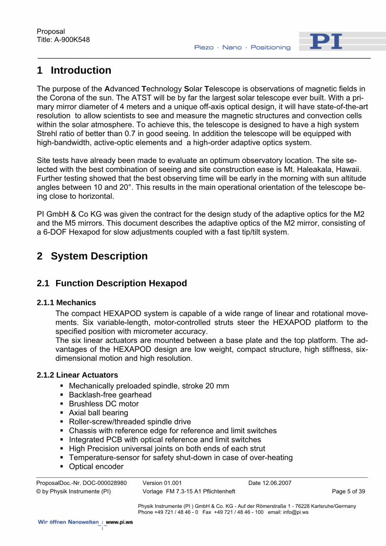
1 Introduction The purpose of the Advanced Technology Solar Telescope is observations of magnetic fields in the Corona of the sun. The ATST will be by far the largest solar telescope ever built. With a pri-mary mirror diameter of 4 meters and a unique off-axis optical design, it will have state-of-the-art resolution to allow scientists to see and measure the magnetic structures and convection cells within the solar atmosphere. To achieve this, the telescope is designed to have a high system Strehl ratio of better than 0.7 in good seeing. In addition the telescope will be equipped with high-bandwidth, active-optic elements and a high-order adaptive optics system. Site tests have already been made to evaluate an optimum observatory location. The site se-lected with the best combination of seeing and site construction ease is Mt. Haleakala, Hawaii. Further testing showed that the best observing time will be early in the morning with sun altitude angles between 10 and 20°. This results in the main operational orientation of the telescope be-ing close to horizontal. PI GmbH & Co KG was given the contract for the design study of the adaptive optics for the M2 and the M5 mirrors. This document describes the adaptive optics of the M2 mirror, consisting of a 6-DOF Hexapod for slow adjustments coupled with a fast tip/tilt system.
2 System Description
2.1 Function Description Hexapod
2.1.1 Mechanics The compact HEXAPOD system is capable of a wide range of linear and rotational move-ments. Six variable-length, motor-controlled struts steer the HEXAPOD platform to the specified position with micrometer accuracy. The six linear actuators are mounted between a base plate and the top platform. The ad-vantages of the HEXAPOD design are low weight, compact structure, high stiffness, six-dimensional motion and high resolution.
2.1.2 Linear Actuators Mechanically preloaded spindle, stroke 20 mm Backlash-free gearhead Brushless DC motor Axial ball bearing Roller-screw/threaded spindle drive Chassis with reference edge for reference and limit switches Integrated PCB with optical reference and limit switches High Precision universal joints on both ends of each strut Temperature-sensor for safety shut-down in case of over-heating Optical encoder
Proposal Title: A-900K548
ProposalDoc.-Nr. DOC-000028980 Version 01.001 Date 12.06.2007 © by Physik Instrumente (PI) Vorlage FM 7.3-15 A1 Pflichtenheft Page 6 of 39
Physik Instrumente (PI ) GmbH & Co. KG - Auf der Römerstraße 1 - 76228 Karlsruhe/Germany Phone +49 721 / 48 46 - 0 Fax +49 721 / 48 46 - 100 email: [email protected]
2.1.3 Details All components are designed to be as short as possible and are mounted free of backlash in axial orientation. This design gives the mechanical system exceptional stiffness and of-fers excellent positioning repeatability. All universal joints use specially manufactured, preloaded needle bearings and are de-signed for extra-high stiffness in the radial direction. They are designed as functional mod-ules that can be manufactured, tested and replaced separately by the manufacturer. The materials and lubricants used are chosen to assure long-term operation in the specified operational environment and temperature range. The U-joint modules allow tilting around two orthogonal axes. Freedom about the third ro-tational axis is provided by the spindle of the linear actuator itself. The operation of the optical limit and reference switches is independent of rotation around the actuator axis: it works without regard to the angular position of the strut end joints. The HEXAPOD base plate contains all motor controllers and electrical connectors. All of the six linear actuators have a brushless-DC motor-driven, backlash-free spindle com-bined with a backlash-free gear head. Each set of lengths for the six linear actuators de-fines exactly one position (location and orientation) of the platform in six degrees of free-dom. It is not possible to cause excessive mechanical stress by driving the legs to some random position. Optional is a Manual Control Pad to allow manual control of hexapod motion in all 6 DoF with programmable step size and velocity with 6 knobs .
2.1.4 Positioning Ranges Because of the special characteristics of the Hexapod design, every movement in one axis influences the available travel range in the other five axes. The following travel ranges are the maximum available travel for movement in only that direction (all other directions at zero position). x,y: -10 to +10 mm z: -10 to +10 mm u,v,w: -3 to +3°
Proposal Title: A-900K548
ProposalDoc.-Nr. DOC-000028980 Version 01.001 Date 12.06.2007 © by Physik Instrumente (PI) Vorlage FM 7.3-15 A1 Pflichtenheft Page 7 of 39
Physik Instrumente (PI ) GmbH & Co. KG - Auf der Römerstraße 1 - 76228 Karlsruhe/Germany Phone +49 721 / 48 46 - 0 Fax +49 721 / 48 46 - 100 email: [email protected]
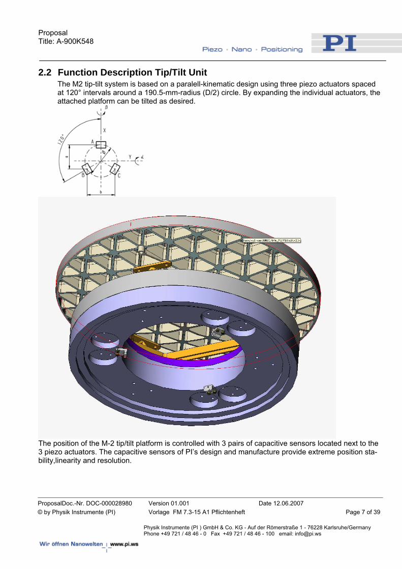
2.2 Function Description Tip/Tilt Unit The M2 tip-tilt system is based on a paralell-kinematic design using three piezo actuators spaced at 120° intervals around a 190.5-mm-radius (D/2) circle. By expanding the individual actuators, the attached platform can be tilted as desired.
The position of the M-2 tip/tilt platform is controlled with 3 pairs of capacitive sensors located next to the 3 piezo actuators. The capacitive sensors of PI’s design and manufacture provide extreme position sta-bility,linearity and resolution.
Proposal Title: A-900K548
ProposalDoc.-Nr. DOC-000028980 Version 01.001 Date 12.06.2007 © by Physik Instrumente (PI) Vorlage FM 7.3-15 A1 Pflichtenheft Page 8 of 39
Physik Instrumente (PI ) GmbH & Co. KG - Auf der Römerstraße 1 - 76228 Karlsruhe/Germany Phone +49 721 / 48 46 - 0 Fax +49 721 / 48 46 - 100 email: [email protected]
3 Technical Specifications All specifications given in this document are theoretical values determined with simulations and calcula-tions. PI’s experienced engineers have determined the values carefully and to their best abilities. There is, however, the possibility that the final product will not meet all values 100%.
3.1 Positioning System Specifications Interfacing to mirror Drawing # ATST-31-4-1-001 M2 Substrate Assembly
and the according 3D SolidWorks model Envelope diameter 550 mm Envelope height 495.5 mm including mirror Free aperture 300 mm on tip/tilt and hexapod movable platform,
355 mm on Hexapod fixed platform to avoid interfer-ence with TMS during operation (see Appendix)
Heat dissipation w/o controller (10 Hz full stroke + 10 microns/min) appr. 10 W (maximum 0.5W for 10Hz full stroke of the Tip/tilt;
Hexapod: 6.5 W; PWM-Driver: 3W) Orientation All orientations Recovery time after power loss < 30 s(<5 s spec) including 10s of booting countdown Response time (2mm step to step motion finished) <5 s (for 0.5mm/s velocity) Shock & vibration (seismic) +2/-1 g axially ±0.5 g laterally (to satisfy ATST original specification) Additional request after the design was completed for the original specifications on how to achieve request for increased seismic spec: Shock & vibration (seismic) 4 g all orientations Comment: The current design of the high speed tip/tilt positioner component on top of the hexapod unit fulfills this increased seismic specification without any design changes. For the hexapod design however we recommend using a braking system on the DC motor that opens only during commanded movements if the position at rest needs to be maintained. The hexapod can sustain 4g loads without damage. This braking system however would in-crease the power dissipation significantly and the position stability could suffer due to thermal expansions caused by the heat dissipation of the brakes. After a seismic event of
Proposal Title: A-900K548
ProposalDoc.-Nr. DOC-000028980 Version 01.001 Date 12.06.2007 © by Physik Instrumente (PI) Vorlage FM 7.3-15 A1 Pflichtenheft Page 9 of 39
Physik Instrumente (PI ) GmbH & Co. KG - Auf der Römerstraße 1 - 76228 Karlsruhe/Germany Phone +49 721 / 48 46 - 0 Fax +49 721 / 48 46 - 100 email: [email protected]
this magnitude braking may not be an issue as many observatory subsystems would have to be reset. A hexapod system reboot would bring the positioner to a fiducial home position and then the ability to relocate to last known position. First mechanical Resonance System with TMS attached 80 Hz (see Appendix) Stiffness of System and TMS attached x,y: 8 N/µm z: 55 N/µm CoG of system w/o TMS see Appendix Weight of the system Hexapod and tip/tilt mechanics ( due to integrated
systems) – 62 kg. Hexapod Section – 27 kg Tip/Tilt Section – 35 kg Mirror ( not supplied) – 17 kg Mirror Interface Plate – 3 kg
Proposal Title: A-900K548
ProposalDoc.-Nr. DOC-000028980 Version 01.001 Date 12.06.2007 © by Physik Instrumente (PI) Vorlage FM 7.3-15 A1 Pflichtenheft Page 10 of 39
Physik Instrumente (PI ) GmbH & Co. KG - Auf der Römerstraße 1 - 76228 Karlsruhe/Germany Phone +49 721 / 48 46 - 0 Fax +49 721 / 48 46 - 100 email: [email protected]
3.2 Hexapod Sub-System Load max. 55 kg Linear travel x,y,z ±10 mm (the travel ranges are the maximum available
travel for movement in only one direction, all other di-rections at zero position)
Rotational travel u,v,w ±3° Velocity max. 0.5 mm/s Velocity Stability +/- 2% after acceleration Minimum incremental motion* 1 µm (with 55kg load) Bidirectional repeatability x,y/z* ±4/±2 µm at 10 mm travel range and
±2/±1 µm at 1 mm travel range (d.g., 3 Sigma, w/o TMS attached)
Repeatability of home position* ±0.5 µm (w/o TMS attached) Accuracy x,y/z* 100/50 µm (3 Sigma, w/o TMS attached) Bidirectional repeatability tip/tilt ±1 µrad (Achievable with tip/tilt sub-system) Accuracy tip/tilt ±5 µrad (Achievable with tip/tilt sub-system) Position stability over 5 min. < ±2 µm (w/o thermal and stiffness influences) Jitter (rotational moves) <0.1 arcsec RMS (system powered on, fixed position) * These specifications can be influenced by the friction of the TMS that is mounted to the
fixed and the moving part of the positioning system, therefore the specifications are stated without TMS attached. Anyway the specifications are valid for a pure load of 55kg.
3.2.1 Specifications for one strut (linear actuator) Travel range: 20 mm Motor: DC-brushless motor Position resolution, motor: 2048 counts/revolution Gear head: Harmonic Drive 100:1 Spindle pitch: 1 mm Resolution (not step size): 0.005 μm Max. push/pull force during operation: 500 N Stiffness: ≥10 N/μm Reference Switch: Position: Center of travel ± 1 mm Signal: TTL Limit Switch: TTL, current limit 40 mA Temperature Switch Power off at 80°C
3.2.2 Calculation of Durability The following calculation of the durability of one strut is based on the following assump-tion:
Proposal Title: A-900K548
ProposalDoc.-Nr. DOC-000028980 Version 01.001 Date 12.06.2007 © by Physik Instrumente (PI) Vorlage FM 7.3-15 A1 Pflichtenheft Page 11 of 39
Physik Instrumente (PI ) GmbH & Co. KG - Auf der Römerstraße 1 - 76228 Karlsruhe/Germany Phone +49 721 / 48 46 - 0 Fax +49 721 / 48 46 - 100 email: [email protected]
- Constant load of 500 N, constant velocity of 0.5 mm/s Spindle
- Dynamic load number of spindle C = 4500 N - Max. axial load (in standard operation) Pa = 500 N Durability L (revolutions)
revxxPCL
a
663
1072910 =⎟⎟⎠
⎞⎜⎜⎝
⎛=
Every cycle consists of 20 revolutions (20 mm travel range, 1 mm spindle pitch):
cyclesxcyclesxL 66 1045.361020
729==
Gearhead
- Ratio i=100 - Torque T at 500 N load: T=0.122 Nm - Max. rpm at continuous operation nN=3500 min-1 - Rpm at v=0.5 mm/s: n=3000 min-1
- Max. torque at continuous operation TN=1.92 Nm
Durability L (hours)
hxTT
nnL NN 6
3
106815000 ≈⎟⎠⎞
⎜⎝⎛=
Every cycle takes 40 seconds (20mm at 0.5 mm/s):
cyclesxcyclesxxL 66 106120106840
3600==
Spindle Bearing
- Dynamic load number of the bearing C=6900 N - Axial load P=500 N
Durability L (revolutions):
revxxPCL 66
3
10262810 =⎟⎠⎞
⎜⎝⎛=
Every cycle consists of 12 revolutions:

Proposal Title: A-900K548
ProposalDoc.-Nr. DOC-000028980 Version 01.001 Date 12.06.2007 © by Physik Instrumente (PI) Vorlage FM 7.3-15 A1 Pflichtenheft Page 12 of 39
Physik Instrumente (PI ) GmbH & Co. KG - Auf der Römerstraße 1 - 76228 Karlsruhe/Germany Phone +49 721 / 48 46 - 0 Fax +49 721 / 48 46 - 100 email: [email protected]
cyclesxcyclesxL 66 101311020
2628≈=
Proposal Title: A-900K548
ProposalDoc.-Nr. DOC-000028980 Version 01.001 Date 12.06.2007 © by Physik Instrumente (PI) Vorlage FM 7.3-15 A1 Pflichtenheft Page 13 of 39
Physik Instrumente (PI ) GmbH & Co. KG - Auf der Römerstraße 1 - 76228 Karlsruhe/Germany Phone +49 721 / 48 46 - 0 Fax +49 721 / 48 46 - 100 email: [email protected]
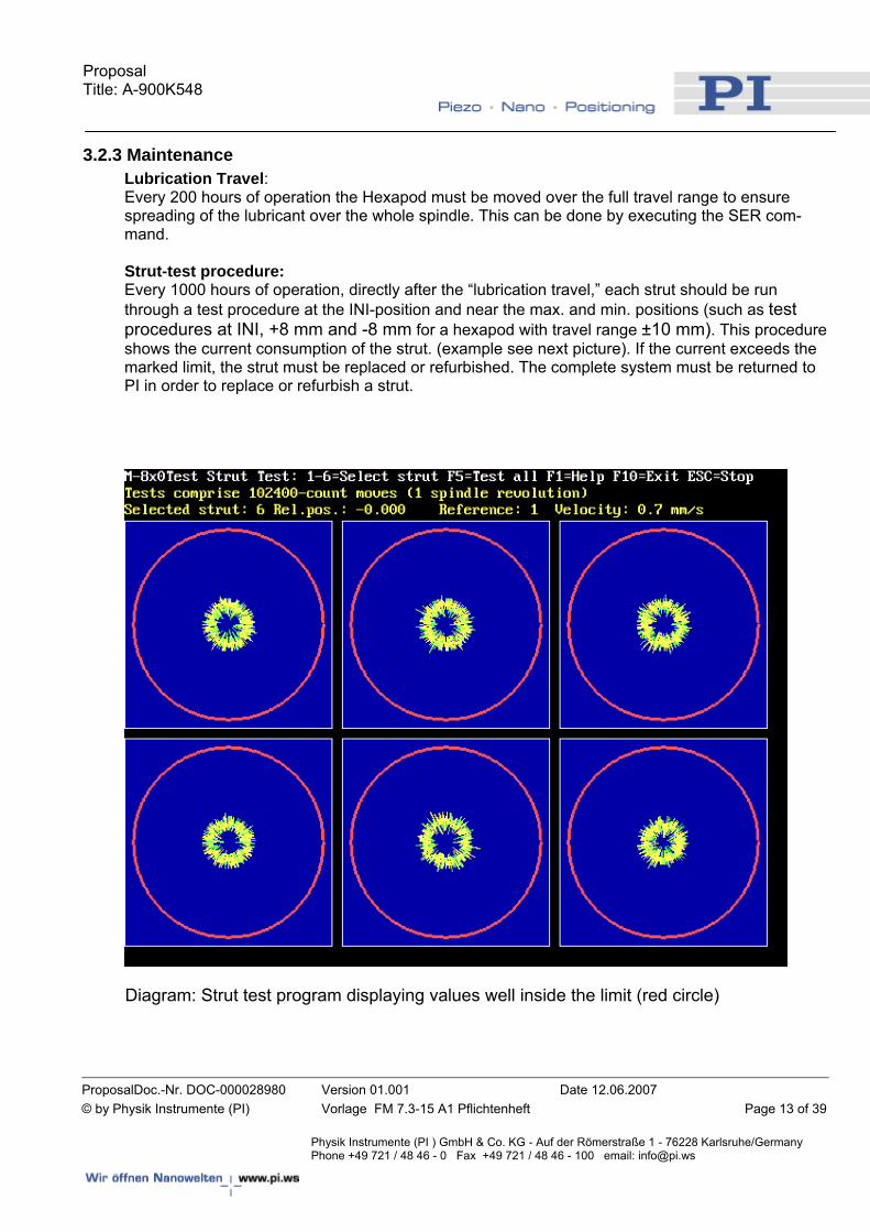
3.2.3 Maintenance Lubrication Travel: Every 200 hours of operation the Hexapod must be moved over the full travel range to ensure spreading of the lubricant over the whole spindle. This can be done by executing the SER com-mand. Strut-test procedure: Every 1000 hours of operation, directly after the “lubrication travel,” each strut should be run through a test procedure at the INI-position and near the max. and min. positions (such as test procedures at INI, +8 mm and -8 mm for a hexapod with travel range ±10 mm). This procedure shows the current consumption of the strut. (example see next picture). If the current exceeds the marked limit, the strut must be replaced or refurbished. The complete system must be returned to PI in order to replace or refurbish a strut.
Diagram: Strut test program displaying values well inside the limit (red circle)
Proposal Title: A-900K548
ProposalDoc.-Nr. DOC-000028980 Version 01.001 Date 12.06.2007 © by Physik Instrumente (PI) Vorlage FM 7.3-15 A1 Pflichtenheft Page 14 of 39
Physik Instrumente (PI ) GmbH & Co. KG - Auf der Römerstraße 1 - 76228 Karlsruhe/Germany Phone +49 721 / 48 46 - 0 Fax +49 721 / 48 46 - 100 email: [email protected]
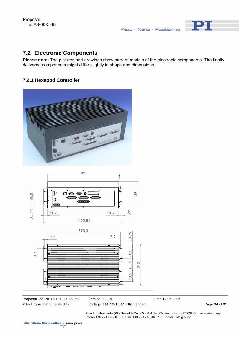
3.2.4 Hexapod Controller The bulk of the Hexapod electronics is contained in the controller. The Hexapod controller contains a multi-axis DC-motor controller and the software needed to transform the user-commands into hardware-specific commands for the six Hexapod motors. It is designed for high-reliability with no moving parts. The controller is itself a PC-based system, and can be operated without keyboard or monitor. For testing purposes, a keyboard and a VGA monitor can be connected to the controller and commands entered there directly. After starting the system, all ASCII-command activity, direct or via the host, will be dis-played on the monitor connected to the controller. Software on the host PC can send ASCII commands to the controller. The controller’s ASCII command interface is fully described in the User Manual, so as enable creation and use of custom software. Data transfer between the Hexapod controller and the host PC is based on an RS-232 or a TCP/IP over Etherlink data link. .
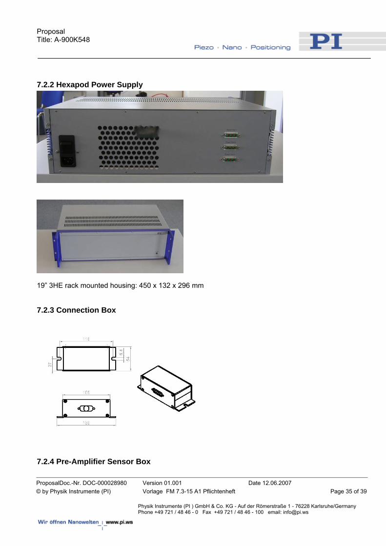
3.2.5 Hexapod Power Supply 24 V 20 A from a separate Power Unit with wide-range input (110-230 VAC, 50-60 Hz).
3.2.6 Hexapod Firmware • The Hexapod controller uses easy-to-understand ASCII commands and the interface is
fully described in the User Manual. • The controller can be operated with a directly connected keyboard and monitor or from a
host computer over an RS232 or TCP/IP over Ethernet interface • On the controller, a diagnostic program can be started that can move single struts in or-
der to test single struts. • A “jog” function will be implemented in the following way: Using a relative move com-
mand , relative moves in all directions can be performed. When sent from the control-ler’s keyboard, this moves will be repeated by any hit on the RETURN key of the control-ler’s keyboard.
• All moves of the Hexapod are dependent on the current pivot point location • The firmware will only allow moves that do not go outside the Hexapod’s working space.
Furthermore, limit switches will prevent the Hexapod from crashing. • A “Hand paddle,” also called “manual control pad” is available as an optional accessory.
There is a velocity set point in the software for the manual control pad. • Homing after inadvertent power-off is not automatic; after re-start, user must initiate.
Upon power-up of the digital controller, the firmware awaits commands only and will not initiate any motion (e.g. in order to put the Hexapod in a well-defined position). All motion is performed in response to explicit commands only.
Proposal Title: A-900K548
ProposalDoc.-Nr. DOC-000028980 Version 01.001 Date 12.06.2007 © by Physik Instrumente (PI) Vorlage FM 7.3-15 A1 Pflichtenheft Page 15 of 39
Physik Instrumente (PI ) GmbH & Co. KG - Auf der Römerstraße 1 - 76228 Karlsruhe/Germany Phone +49 721 / 48 46 - 0 Fax +49 721 / 48 46 - 100 email: [email protected]
3.2.7 Hexapod Software The system comes with a comprehensive software package ranging from a simple graph-ics user interface terminal application to a control program with user-controllable graphic representation of the hardware. Also included are fully-documented Windows DLL, COM object and LabVIEW drivers to handle communications and low-level functionality, thus fa-cilitating creation of custom software.
3.3 Tip/Tilt Sub-System
3.3.1 Tip/tilt Mechanics Load: 16,5 kg M2 Mirror including bipod flexures Interface to mirror: The flexure plate can be made of one of two different materials, as
specified by the customer: a) Invar (Ni36/1.3912) CTE (RT) ~ 0.8*10-3 K-1 b) Invar (Ni42/1.3917) CTE (RT) ~ 5.6*10-3 K-1
Vertex Rotation: Vertex position see appendix: dimensional drawing Travel: ± 75 µrad Repeatability: ± 1 µrad (3 Sigma) Accuracy: ± 5 µrad (3 Sigma) Dynamic Setting: Max. 10% overshoot for full stroke Resonant frequency: 280 Hz (see Appendix) Bandwidth (-3dB): 86Hz, limited to 70Hz well below the system resonance of 80Hz (see Appendix) Phase Shift: -14.7° @ 10Hz (for 70Hz bandwidth, see Appendix) Sensor type: capacitive Actuator: PICMA tripod El. Capacitance (small signal): 13 µF/axis Momentum compensation: not required
3.3.2 Tip/tilt Controller Multi-channel digital controller such as E-710.3CD or successor, depending on the order date. Standard interfaces for E-710 controllers are RS-232 and analog input. For later models Ethernet interface will be optional available.
Proposal Title: A-900K548
ProposalDoc.-Nr. DOC-000028980 Version 01.001 Date 12.06.2007 © by Physik Instrumente (PI) Vorlage FM 7.3-15 A1 Pflichtenheft Page 16 of 39
Physik Instrumente (PI ) GmbH & Co. KG - Auf der Römerstraße 1 - 76228 Karlsruhe/Germany Phone +49 721 / 48 46 - 0 Fax +49 721 / 48 46 - 100 email: [email protected]
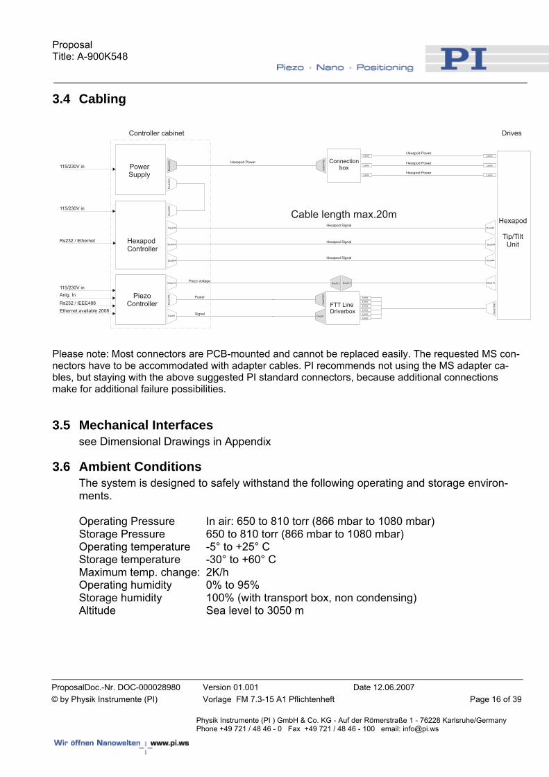
3.4 Cabling
Hexapod
Tip/TiltUnit
Drives
HexapodController
PiezoController FTT Line
Driverbox
Power
Signal
Piezo VoltageDsub15 Dsub15 Dsub15
Dsub44
Dsub44
Dsub44
Dsub44
Dsub44
Dsu
b3W
3D
sub3
W3
Dsu
b3W
3
Dsu
b13W
3
Dsub3W
3Dsub44
Dsub15
Dsub9
Dsu
b7W
2
Dsu
b7W
2
Dsub9
Lemo Lemo
Lemo Lemo
Lemo Lemo
Controller cabinet
PowerSupply
Lemo
Lemo
Lemo
Lemo
Lemo
Lemo
Connectionbox
Hexapod Signal
Hexapod Signal
Hexapod Power
Hexapod Power
Hexapod Power
Hexapod Power
Hexapod Signal
115/230V in
115/230V in
115/230V in
Rs232 / Ethernet
Rs232 / IEEE488
Anlg. In
Ethernet available 2008
Cable length max.20m
Please note: Most connectors are PCB-mounted and cannot be replaced easily. The requested MS con-nectors have to be accommodated with adapter cables. PI recommends not using the MS adapter ca-bles, but staying with the above suggested PI standard connectors, because additional connections make for additional failure possibilities.
3.5 Mechanical Interfaces see Dimensional Drawings in Appendix
3.6 Ambient Conditions The system is designed to safely withstand the following operating and storage environ-ments. Operating Pressure In air: 650 to 810 torr (866 mbar to 1080 mbar) Storage Pressure 650 to 810 torr (866 mbar to 1080 mbar) Operating temperature -5° to +25° C Storage temperature -30° to +60° C Maximum temp. change: 2K/h Operating humidity 0% to 95% Storage humidity 100% (with transport box, non condensing) Altitude Sea level to 3050 m
Proposal Title: A-900K548
ProposalDoc.-Nr. DOC-000028980 Version 01.001 Date 12.06.2007 © by Physik Instrumente (PI) Vorlage FM 7.3-15 A1 Pflichtenheft Page 17 of 39
Physik Instrumente (PI ) GmbH & Co. KG - Auf der Römerstraße 1 - 76228 Karlsruhe/Germany Phone +49 721 / 48 46 - 0 Fax +49 721 / 48 46 - 100 email: [email protected]
4 Tests Required
In principle the specifications for hexapod and tip/tilt sub-systems are tested individually. But the testing is performed with both sub-systems mounted together and a dummy mirror attached. For the Hexapod incremental motion, repeatability (x,y,z) and positioning accu-racy will be measured in our standard procedure for Hexapod measurement. For the tip/tilt sub-system the specifications such as resonance frequency, bandwidth and phase lag will be measured with dummy mirror attached.
5 Supplied Documentation
Please note: The supplied manuals describe current existing products. By time we deliver the goods described herein successor models might be delivered with slightly different software commands and/or functionalities. - Existing Software Manuals for similar standard Hexapod Controller: LabView MS91E,
GCSLabView MS93E, Dll MS71E, COM MS111E, Control MS57E
- Existing Manual for similar customized Hexapod: M840K013_User MS171E
- Existing Manuals for similar standard Tip/tilt Digital Controller: E-710_GCSLabView
PZ141E, E-710_GCSDll PZ147E, E-710_User PZ80E; GCSData_User SM146E, Nano-
Capture SM071E, PZTControl PZ145E
- CD-ROM containing:
• all above listed documentation
• this document
• SolidWorks 3D model
• Dimensional drawings
• Simulation program of Hexapod movements
• Avi files of mechanical resonances
• Matlab model of transfer function

Proposal Title: A-900K548
ProposalDoc.-Nr. DOC-000028980 Version 01.001 Date 12.06.2007 © by Physik Instrumente (PI) Vorlage FM 7.3-15 A1 Pflichtenheft Page 18 of 39
Physik Instrumente (PI ) GmbH & Co. KG - Auf der Römerstraße 1 - 76228 Karlsruhe/Germany Phone +49 721 / 48 46 - 0 Fax +49 721 / 48 46 - 100 email: [email protected]
6 Organization
6.1 Time Schedule for goods being ordered Design release depends on requested changes to the design described herein
Goods receiving 12 weeks after design release
Manufacturing 16 weeks after design release
Metrology 18 weeks after design release
Product release 18 weeks after design release
Packaging & Shipping 19 weeks after design release
6.2 Team Karin Hernandez (KHe) Mechanics (Hexapod) Ralf Krämer (RKr) Mechanics and Specifications (Hexapod) Klaus Pollak (KPo) Mechanics (Tip/Tilt) Christoph Stiebel (STIE) Electronics (Hexapod) Christopher Mock (CMo) Electronics (Tip/Tilt) Erik Mankin (EMa) Firmware/Software Matthias Schulz (MSz) Cables

Proposal Title: A-900K548
ProposalDoc.-Nr. DOC-000028980 Version 01.001 Date 12.06.2007 © by Physik Instrumente (PI) Vorlage FM 7.3-15 A1 Pflichtenheft Page 19 of 39
Physik Instrumente (PI ) GmbH & Co. KG - Auf der Römerstraße 1 - 76228 Karlsruhe/Germany Phone +49 721 / 48 46 - 0 Fax +49 721 / 48 46 - 100 email: [email protected]
7 Appendix
Proposal Title: A-900K548
ProposalDoc.-Nr. DOC-000028980 Version 01.001 Date 12.06.2007 © by Physik Instrumente (PI) Vorlage FM 7.3-15 A1 Pflichtenheft Page 20 of 39
Physik Instrumente (PI ) GmbH & Co. KG - Auf der Römerstraße 1 - 76228 Karlsruhe/Germany Phone +49 721 / 48 46 - 0 Fax +49 721 / 48 46 - 100 email: [email protected]
7.1 Simulation Diagrams
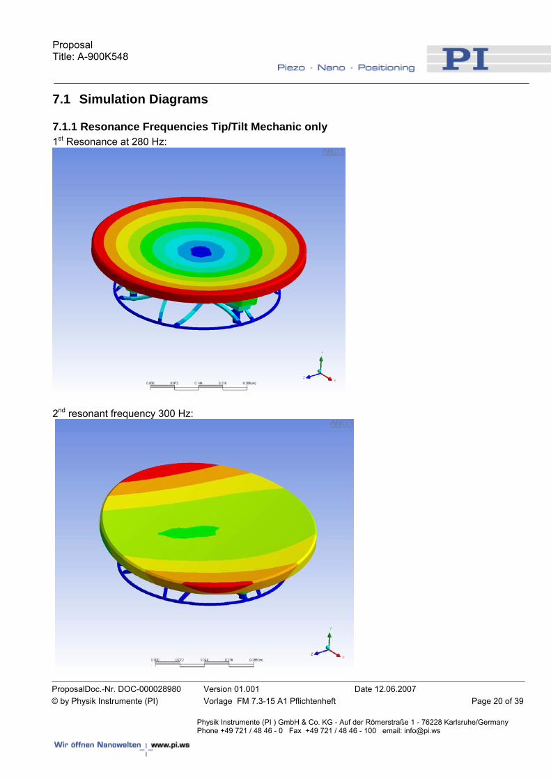
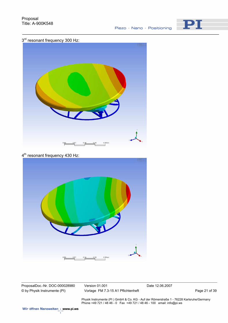
7.1.1 Resonance Frequencies Tip/Tilt Mechanic only 1st Resonance at 280 Hz:
2nd resonant frequency 300 Hz:
Proposal Title: A-900K548
ProposalDoc.-Nr. DOC-000028980 Version 01.001 Date 12.06.2007 © by Physik Instrumente (PI) Vorlage FM 7.3-15 A1 Pflichtenheft Page 21 of 39
Physik Instrumente (PI ) GmbH & Co. KG - Auf der Römerstraße 1 - 76228 Karlsruhe/Germany Phone +49 721 / 48 46 - 0 Fax +49 721 / 48 46 - 100 email: [email protected]
3rd resonant frequency 300 Hz:
4th resonant frequency 430 Hz:
Proposal Title: A-900K548
ProposalDoc.-Nr. DOC-000028980 Version 01.001 Date 12.06.2007 © by Physik Instrumente (PI) Vorlage FM 7.3-15 A1 Pflichtenheft Page 22 of 39
Physik Instrumente (PI ) GmbH & Co. KG - Auf der Römerstraße 1 - 76228 Karlsruhe/Germany Phone +49 721 / 48 46 - 0 Fax +49 721 / 48 46 - 100 email: [email protected]
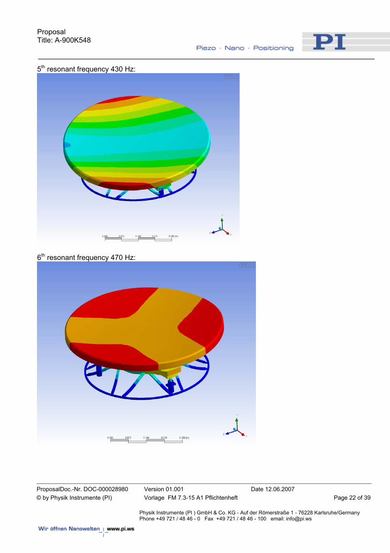
5th resonant frequency 430 Hz:
6th resonant frequency 470 Hz:
Proposal Title: A-900K548
ProposalDoc.-Nr. DOC-000028980 Version 01.001 Date 12.06.2007 © by Physik Instrumente (PI) Vorlage FM 7.3-15 A1 Pflichtenheft Page 23 of 39
Physik Instrumente (PI ) GmbH & Co. KG - Auf der Römerstraße 1 - 76228 Karlsruhe/Germany Phone +49 721 / 48 46 - 0 Fax +49 721 / 48 46 - 100 email: [email protected]
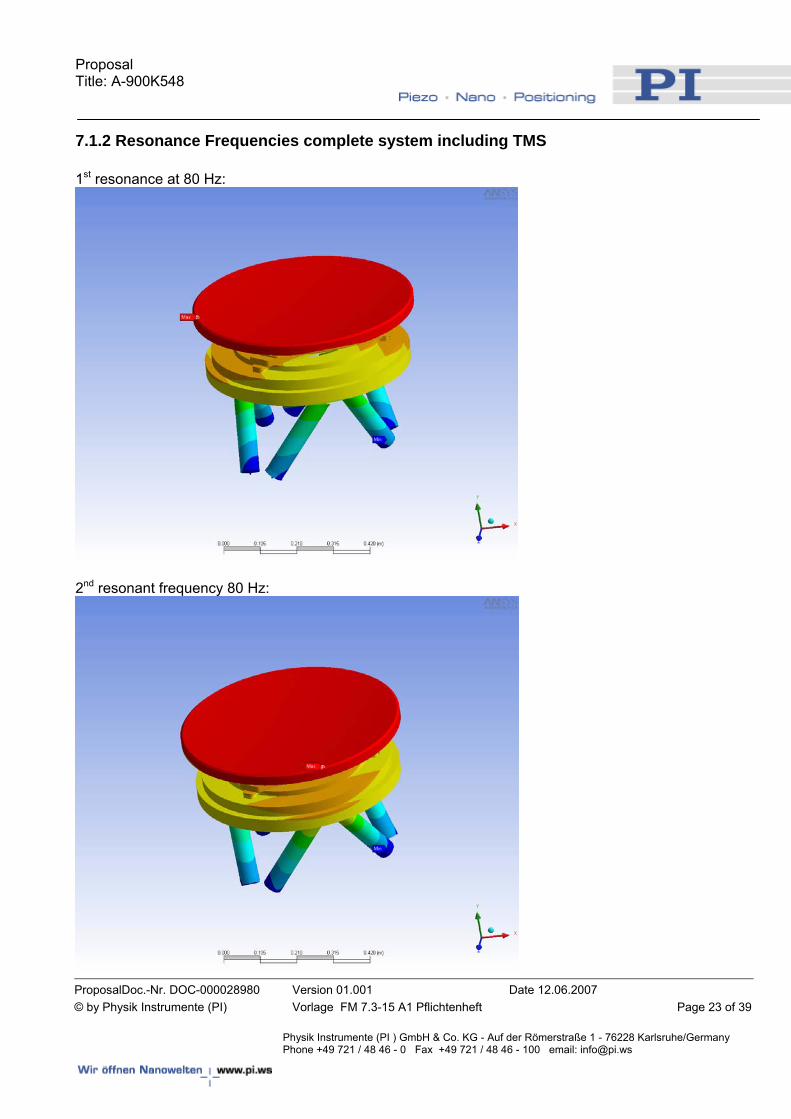
7.1.2 Resonance Frequencies complete system including TMS 1st resonance at 80 Hz:
2nd resonant frequency 80 Hz:
Proposal Title: A-900K548
ProposalDoc.-Nr. DOC-000028980 Version 01.001 Date 12.06.2007 © by Physik Instrumente (PI) Vorlage FM 7.3-15 A1 Pflichtenheft Page 24 of 39
Physik Instrumente (PI ) GmbH & Co. KG - Auf der Römerstraße 1 - 76228 Karlsruhe/Germany Phone +49 721 / 48 46 - 0 Fax +49 721 / 48 46 - 100 email: [email protected]
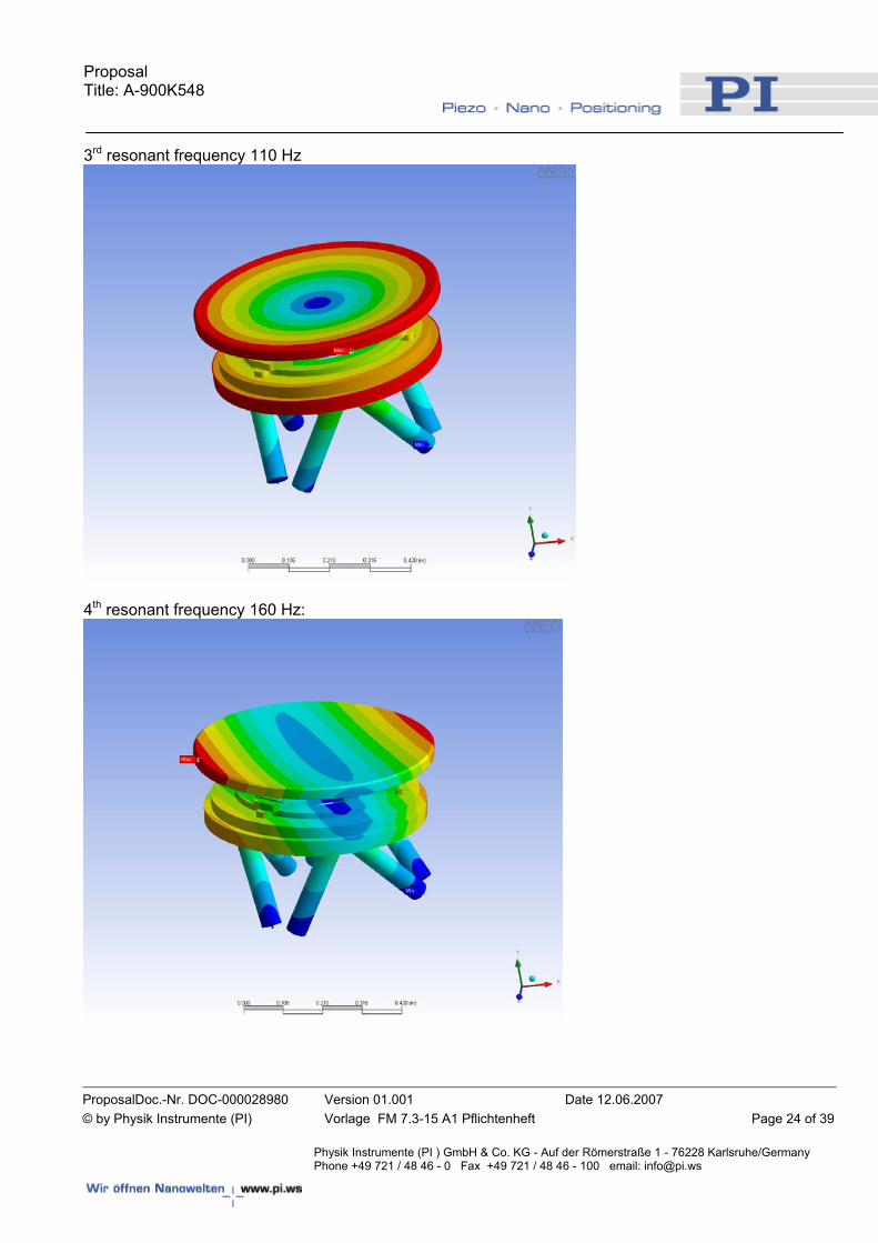
3rd resonant frequency 110 Hz
4th resonant frequency 160 Hz:
Proposal Title: A-900K548
ProposalDoc.-Nr. DOC-000028980 Version 01.001 Date 12.06.2007 © by Physik Instrumente (PI) Vorlage FM 7.3-15 A1 Pflichtenheft Page 25 of 39
Physik Instrumente (PI ) GmbH & Co. KG - Auf der Römerstraße 1 - 76228 Karlsruhe/Germany Phone +49 721 / 48 46 - 0 Fax +49 721 / 48 46 - 100 email: [email protected]
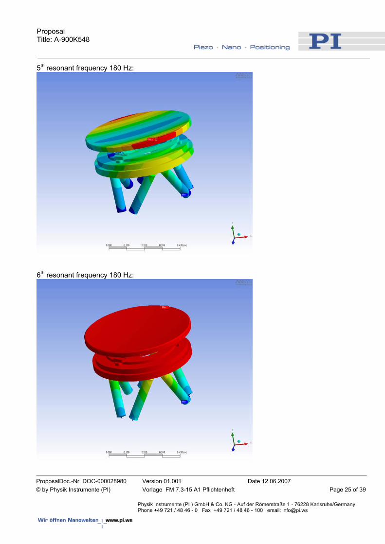
5th resonant frequency 180 Hz:
6th resonant frequency 180 Hz:
Proposal Title: A-900K548
ProposalDoc.-Nr. DOC-000028980 Version 01.001 Date 12.06.2007 © by Physik Instrumente (PI) Vorlage FM 7.3-15 A1 Pflichtenheft Page 26 of 39
Physik Instrumente (PI ) GmbH & Co. KG - Auf der Römerstraße 1 - 76228 Karlsruhe/Germany Phone +49 721 / 48 46 - 0 Fax +49 721 / 48 46 - 100 email: [email protected]
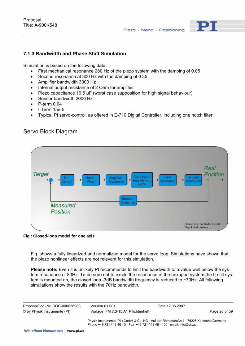
7.1.3 Bandwidth and Phase Shift Simulation Simulation is based on the following data:
• First mechanical resonance 280 Hz of the piezo system with the damping of 0.05 • Second resonance at 300 Hz with the damping of 0.35 • Amplifier bandwidth 3000 Hz • Internal output resistance of 2 Ohm for amplifier • Piezo capacitance 19.5 µF (worst case supposition for high signal behaviour) • Sensor bandwidth 2000 Hz • P-term 0.04 • I-Term 15e-5 • Typical PI servo-control, as offered in E-710 Digital Controller, including one notch filter
Servo Block Diagram
Fig.: Closed-loop model for one axis
Fig. shows a fully linearized and normalized model for the servo loop. Simulations have shown that the piezo nonlinear effects are not relevant for this simulation. Please note: Even it is unlikely PI recommends to limit the bandwidth to a value well below the sys-tem resonance of 80Hz. To be sure not to excite the resonance of the hexapod system the tip-tilt sys-tem is mounted on, the closed loop -3dB bandwidth frequency is reduced to ~70Hz. All following simulations show the results with the 70Hz bandwidth.
Proposal Title: A-900K548
ProposalDoc.-Nr. DOC-000028980 Version 01.001 Date 12.06.2007 © by Physik Instrumente (PI) Vorlage FM 7.3-15 A1 Pflichtenheft Page 27 of 39
Physik Instrumente (PI ) GmbH & Co. KG - Auf der Römerstraße 1 - 76228 Karlsruhe/Germany Phone +49 721 / 48 46 - 0 Fax +49 721 / 48 46 - 100 email: [email protected]
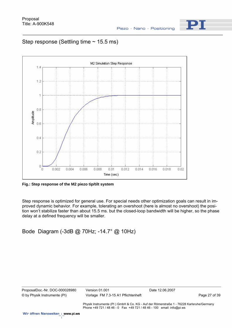
Step response (Settling time ~ 15.5 ms)
Fig.: Step response of the M2 piezo tip/tilt system
Step response is optimized for general use. For special needs other optimization goals can result in im-proved dynamic behavior. For example, tolerating an overshoot (here is almost no overshoot) the posi-tion won’t stabilize faster than about 15.5 ms. but the closed-loop bandwidth will be higher, so the phase delay at a defined frequency will be smaller. Bode Diagram (-3dB @ 70Hz; -14.7° @ 10Hz)
Proposal Title: A-900K548
ProposalDoc.-Nr. DOC-000028980 Version 01.001 Date 12.06.2007 © by Physik Instrumente (PI) Vorlage FM 7.3-15 A1 Pflichtenheft Page 28 of 39
Physik Instrumente (PI ) GmbH & Co. KG - Auf der Römerstraße 1 - 76228 Karlsruhe/Germany Phone +49 721 / 48 46 - 0 Fax +49 721 / 48 46 - 100 email: [email protected]
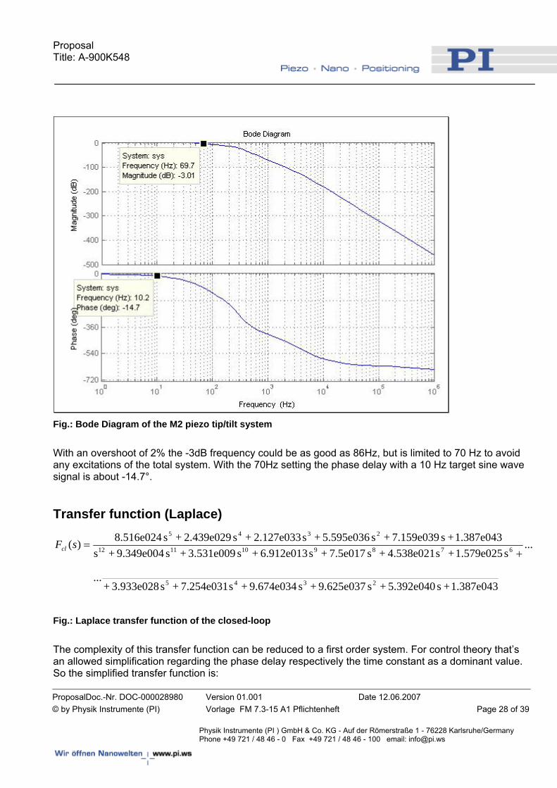
Fig.: Bode Diagram of the M2 piezo tip/tilt system
With an overshoot of 2% the -3dB frequency could be as good as 86Hz, but is limited to 70 Hz to avoid any excitations of the total system. With the 70Hz setting the phase delay with a 10 Hz target sine wave signal is about -14.7°. Transfer function (Laplace)
...
1.387e043 + s 5.392e040 + s 9.625e037 + s 9.674e034 + s 7.254e031 + s 3.933e028 +...
s 1.579e025 + s 4.538e021 + s 7.5e017 + s 6.912e013 + s 3.531e009 + s 9.349e004 + s1.387e043 + s 7.159e039 + s 5.595e036 + s 2.127e033 + s 2.439e029 + s 8.516e024)(
2345
6789101112
2345
+=sFcl
Fig.: Laplace transfer function of the closed-loop
The complexity of this transfer function can be reduced to a first order system. For control theory that’s an allowed simplification regarding the phase delay respectively the time constant as a dominant value. So the simplified transfer function is:
Proposal Title: A-900K548
ProposalDoc.-Nr. DOC-000028980 Version 01.001 Date 12.06.2007 © by Physik Instrumente (PI) Vorlage FM 7.3-15 A1 Pflichtenheft Page 29 of 39
Physik Instrumente (PI ) GmbH & Co. KG - Auf der Römerstraße 1 - 76228 Karlsruhe/Germany Phone +49 721 / 48 46 - 0 Fax +49 721 / 48 46 - 100 email: [email protected]
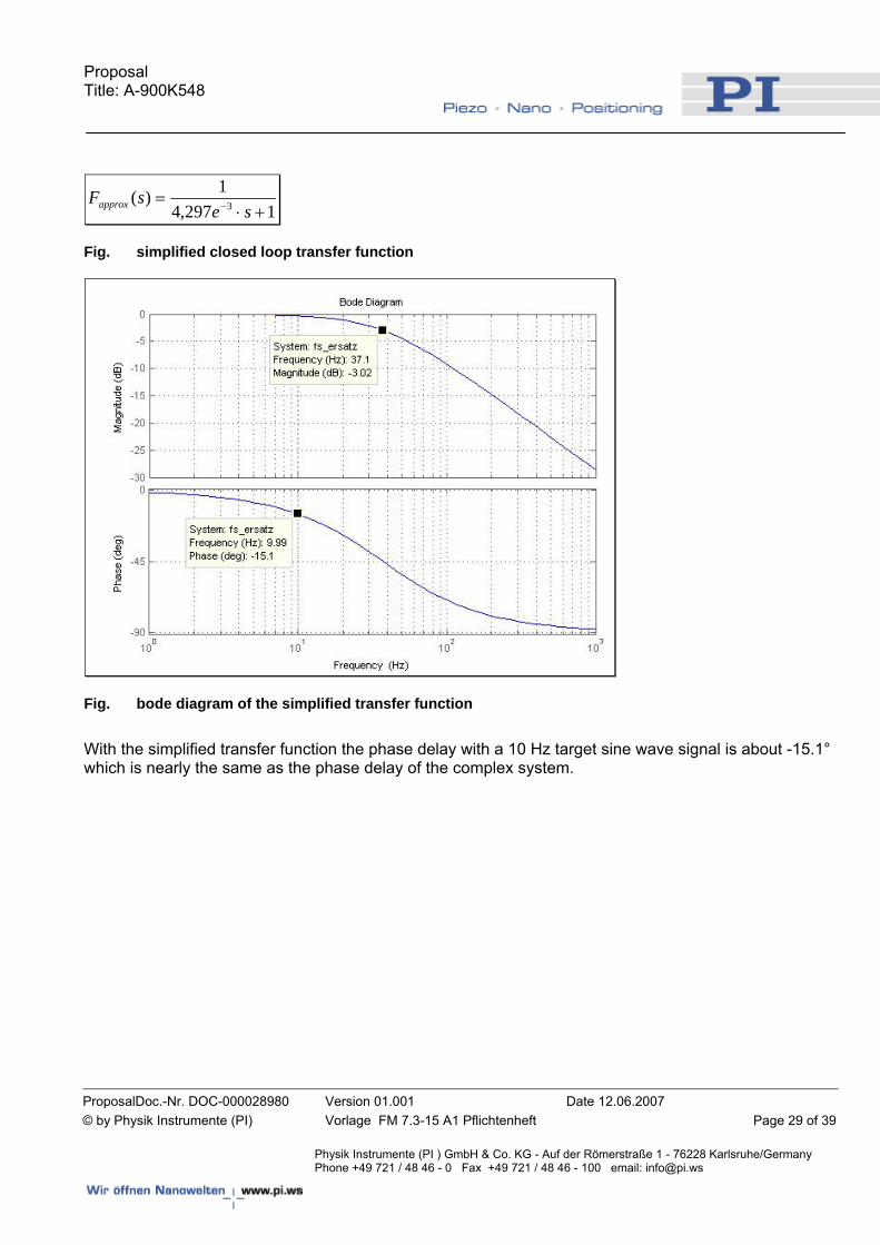
1297,41)( 3 +⋅
= − sesFapprox
Fig. simplified closed loop transfer function
Fig. bode diagram of the simplified transfer function
With the simplified transfer function the phase delay with a 10 Hz target sine wave signal is about -15.1° which is nearly the same as the phase delay of the complex system.
Proposal Title: A-900K548
ProposalDoc.-Nr. DOC-000028980 Version 01.001 Date 12.06.2007 © by Physik Instrumente (PI) Vorlage FM 7.3-15 A1 Pflichtenheft Page 30 of 39
Physik Instrumente (PI ) GmbH & Co. KG - Auf der Römerstraße 1 - 76228 Karlsruhe/Germany Phone +49 721 / 48 46 - 0 Fax +49 721 / 48 46 - 100 email: [email protected]
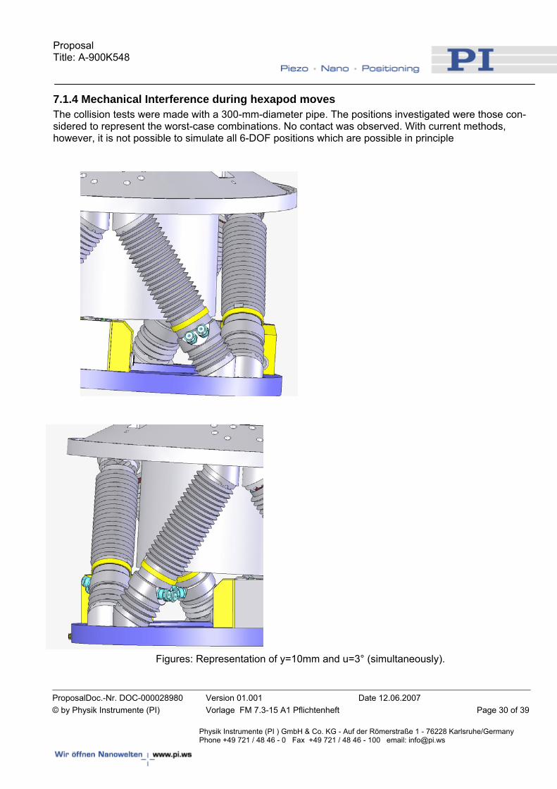
7.1.4 Mechanical Interference during hexapod moves The collision tests were made with a 300-mm-diameter pipe. The positions investigated were those con-sidered to represent the worst-case combinations. No contact was observed. With current methods, however, it is not possible to simulate all 6-DOF positions which are possible in principle
Figures: Representation of y=10mm and u=3° (simultaneously).
Proposal Title: A-900K548
ProposalDoc.-Nr. DOC-000028980 Version 01.001 Date 12.06.2007 © by Physik Instrumente (PI) Vorlage FM 7.3-15 A1 Pflichtenheft Page 31 of 39
Physik Instrumente (PI ) GmbH & Co. KG - Auf der Römerstraße 1 - 76228 Karlsruhe/Germany Phone +49 721 / 48 46 - 0 Fax +49 721 / 48 46 - 100 email: [email protected]
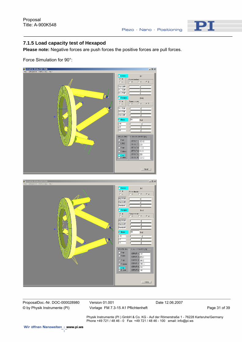
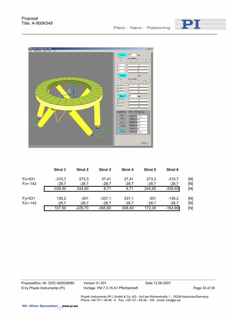
7.1.5 Load capacity test of Hexapod Please note: Negative forces are push forces the positive forces are pull forces. Force Simulation for 90°:
Proposal Title: A-900K548
ProposalDoc.-Nr. DOC-000028980 Version 01.001 Date 12.06.2007 © by Physik Instrumente (PI) Vorlage FM 7.3-15 A1 Pflichtenheft Page 32 of 39
Physik Instrumente (PI ) GmbH & Co. KG - Auf der Römerstraße 1 - 76228 Karlsruhe/Germany Phone +49 721 / 48 46 - 0 Fax +49 721 / 48 46 - 100 email: [email protected]
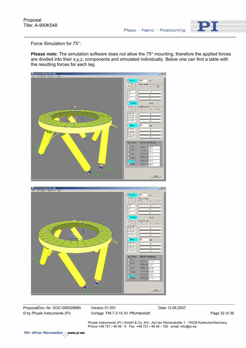
Force Simulation for 75°: Please note: The simulation software does not allow the 75° mounting, therefore the applied forces are divided into their x,y,z, components and simulated individually. Below one can find a table with the resulting forces for each leg.
Proposal Title: A-900K548
ProposalDoc.-Nr. DOC-000028980 Version 01.001 Date 12.06.2007 © by Physik Instrumente (PI) Vorlage FM 7.3-15 A1 Pflichtenheft Page 33 of 39
Physik Instrumente (PI ) GmbH & Co. KG - Auf der Römerstraße 1 - 76228 Karlsruhe/Germany Phone +49 721 / 48 46 - 0 Fax +49 721 / 48 46 - 100 email: [email protected]
Strut 1 Strut 2 Strut 3 Strut 4 Strut 5 Strut 6
Fx=531 -310,7 273,3 37,41 37,41 273,3 -310,7 [N]Fz=-142 -28,7 -28,7 -28,7 -28,7 -28,7 -28,7 [N]
-339,40 244,60 8,71 8,71 244,60 -339,40 [N]
Fy=531 136,2 -201 -337,1 337,1 201 -136,2 [N]Fz=-142 -28,7 -28,7 -28,7 -28,7 -28,7 -28,7 [N]
107,50 -229,70 -365,80 308,40 172,30 -164,90 [N]
Proposal Title: A-900K548
ProposalDoc.-Nr. DOC-000028980 Version 01.001 Date 12.06.2007 © by Physik Instrumente (PI) Vorlage FM 7.3-15 A1 Pflichtenheft Page 34 of 39
Physik Instrumente (PI ) GmbH & Co. KG - Auf der Römerstraße 1 - 76228 Karlsruhe/Germany Phone +49 721 / 48 46 - 0 Fax +49 721 / 48 46 - 100 email: [email protected]
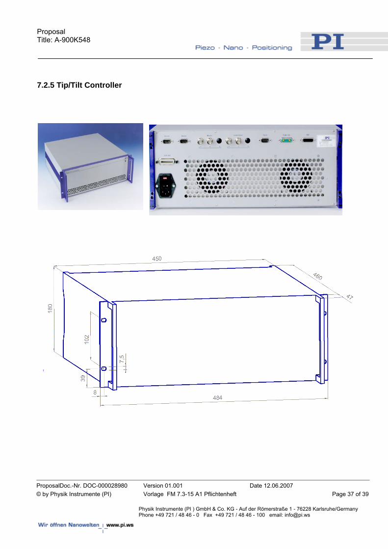
7.2 Electronic Components Please note: The pictures and drawings show current models of the electronic components. The finally delivered components might differ slightly in shape and dimensions.
7.2.1 Hexapod Controller
Proposal Title: A-900K548
ProposalDoc.-Nr. DOC-000028980 Version 01.001 Date 12.06.2007 © by Physik Instrumente (PI) Vorlage FM 7.3-15 A1 Pflichtenheft Page 35 of 39
Physik Instrumente (PI ) GmbH & Co. KG - Auf der Römerstraße 1 - 76228 Karlsruhe/Germany Phone +49 721 / 48 46 - 0 Fax +49 721 / 48 46 - 100 email: [email protected]
7.2.2 Hexapod Power Supply
19” 3HE rack mounted housing: 450 x 132 x 296 mm
7.2.3 Connection Box
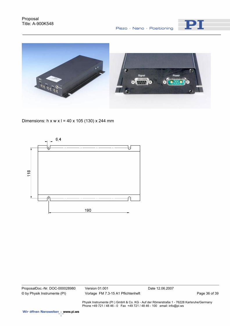
7.2.4 Pre-Amplifier Sensor Box
Proposal Title: A-900K548
ProposalDoc.-Nr. DOC-000028980 Version 01.001 Date 12.06.2007 © by Physik Instrumente (PI) Vorlage FM 7.3-15 A1 Pflichtenheft Page 36 of 39
Physik Instrumente (PI ) GmbH & Co. KG - Auf der Römerstraße 1 - 76228 Karlsruhe/Germany Phone +49 721 / 48 46 - 0 Fax +49 721 / 48 46 - 100 email: [email protected]
Dimensions: h x w x l = 40 x 105 (130) x 244 mm
Proposal Title: A-900K548
ProposalDoc.-Nr. DOC-000028980 Version 01.001 Date 12.06.2007 © by Physik Instrumente (PI) Vorlage FM 7.3-15 A1 Pflichtenheft Page 37 of 39
Physik Instrumente (PI ) GmbH & Co. KG - Auf der Römerstraße 1 - 76228 Karlsruhe/Germany Phone +49 721 / 48 46 - 0 Fax +49 721 / 48 46 - 100 email: [email protected]
7.2.5 Tip/Tilt Controller
Proposal Title: A-900K548
ProposalDoc.-Nr. DOC-000028980 Version 01.001 Date 12.06.2007 © by Physik Instrumente (PI) Vorlage FM 7.3-15 A1 Pflichtenheft Page 38 of 39
Physik Instrumente (PI ) GmbH & Co. KG - Auf der Römerstraße 1 - 76228 Karlsruhe/Germany Phone +49 721 / 48 46 - 0 Fax +49 721 / 48 46 - 100 email: [email protected]
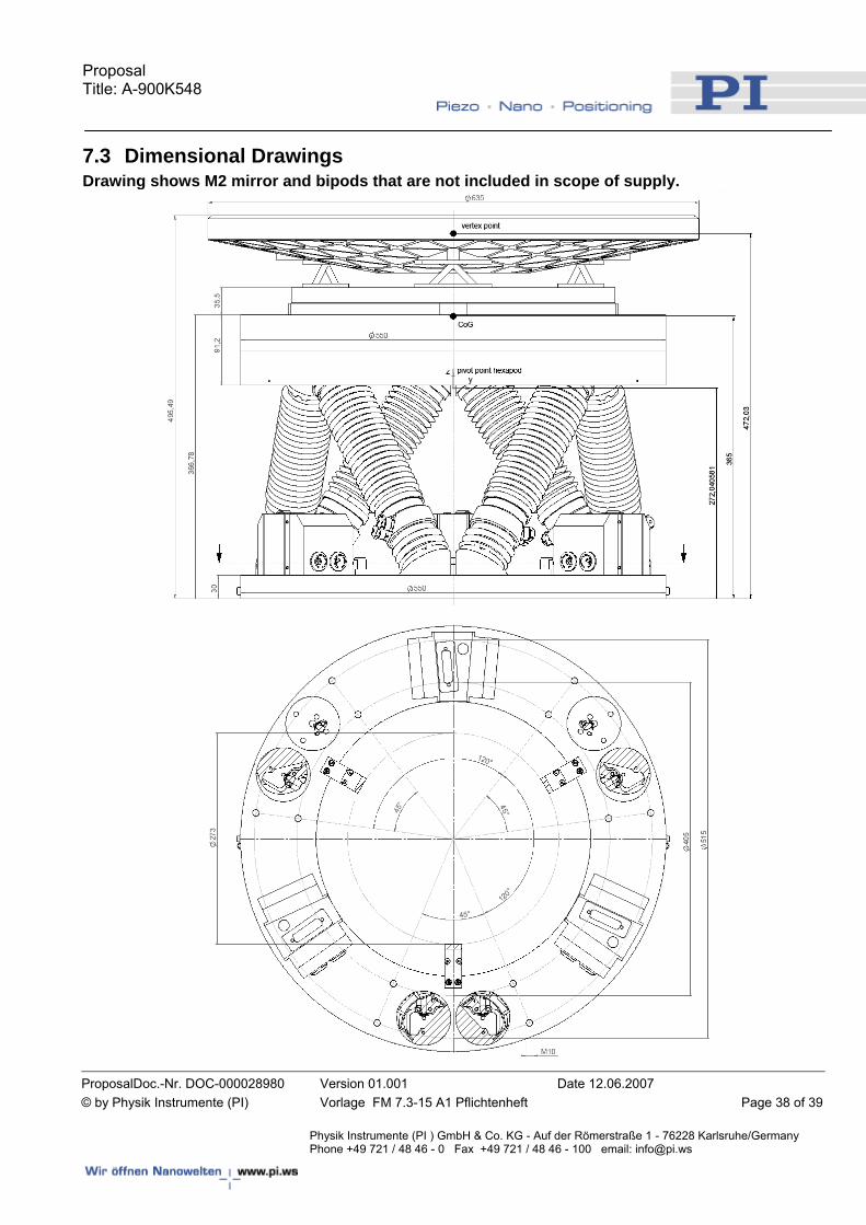
7.3 Dimensional Drawings Drawing shows M2 mirror and bipods that are not included in scope of supply.
Proposal Title: A-900K548
ProposalDoc.-Nr. DOC-000028980 Version 01.001 Date 12.06.2007 © by Physik Instrumente (PI) Vorlage FM 7.3-15 A1 Pflichtenheft Page 39 of 39
Physik Instrumente (PI ) GmbH & Co. KG - Auf der Römerstraße 1 - 76228 Karlsruhe/Germany Phone +49 721 / 48 46 - 0 Fax +49 721 / 48 46 - 100 email: [email protected]
7.4 Miscellaneous : A number of items discussed in the Final Design Review are better addressed when the assembly and integration details for the system are better defined. These are small but important user interface details that will not add any significant cost
These are identified here for future consideration:
Lifting handles – location depends on method of installing mirror and positioner into struc-ture. Does tip/tilt hexapod need to be lifted in vertical or horizontal position…or does lift-ing lug/handles need to provide for both? Mirror Fastening Screws – M4 or M6?, M6 are possible and it is feasible to access M6 screws from back plate of hexapod if access holes are in appropriate place depending on final TMS & Interface to structure details.