Embed Size (px)
Citation preview
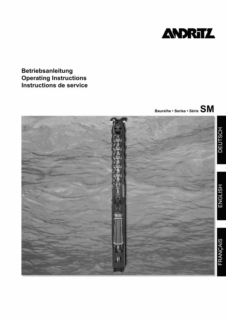
BetriebsanleitungOperating InstructionsInstructions de service
Baureihe • Series • Série SM
DE
UT
SC
HE
NG
LIS
HF
RA
NÇ
AIS
Baureihe SM
DE
UT
SC
H
Inhaltsverzeichnis Seite
1. Allgemein .................................................................................................................................41.1 Einleitung ............................................................................................................................................................................. 41.2 Benennung........................................................................................................................................................................... 41.3 Fabrikschild .......................................................................................................................................................................... 41.4 Sicherheitshinweise ............................................................................................................................................................. 4
2. Unbedingt beachten................................................................................................................42.1 Verwendungszweck ............................................................................................................................................................. 42.2 Anforderungen beim Einsatz................................................................................................................................................ 52.3 Anforderungen der EG-Richtlinien ....................................................................................................................................... 6
3. Transport und Lagerung.........................................................................................................63.1 Transportieren...................................................................................................................................................................... 63.2 Lagerung .............................................................................................................................................................................. 63.3 Auspacken ........................................................................................................................................................................... 73.4 Erste Überprüfung................................................................................................................................................................ 7
4. Motor montieren ......................................................................................................................74.1 Benötigtes Werkzeug ........................................................................................................................................................... 74.2 Auffüllen des Motors ............................................................................................................................................................ 74.3 Zusammenbau von Motor und Pumpe (Aggregat)............................................................................................................... 74.4 Motorkabel anschließen ....................................................................................................................................................... 8
5. Elektrischer Anschluss...........................................................................................................85.1 Voraussetzungen ................................................................................................................................................................. 85.2 Energieversorgung............................................................................................................................................................... 85.3 Motor anschließen................................................................................................................................................................ 9
6. Inbetriebnahme......................................................................................................................106.1 Voraussetzungen ............................................................................................................................................................... 106.2 Prüfung vor der Inbetriebnahme ........................................................................................................................................ 106.3 Motor einschalten............................................................................................................................................................... 106.4 Beim Testbetrieb ................................................................................................................................................................ 10
7. Wartung..................................................................................................................................118.1 Allgemein ........................................................................................................................................................................... 118.2 Elektrische Störungen........................................................................................................................................................ 11
8. Störungen : Ursachen und Beseitigung..............................................................................118.1 Allgemein ........................................................................................................................................................................... 118.2 Elektrische Störungen........................................................................................................................................................ 118.3 Mechanische oder hydraulische Störungen....................................................................................................................... 118.4 Störungen im Überblick...................................................................................................................................................... 12
9. Anhang ...................................................................................................................................339.1 Richtwerttabellen für Kühlmitteltemperaturen .................................................................................................................... 339.2 Anschlussplan PT100 mit Ausgleichsleitung...................................................................................................................... 40
3
Baureihe SM
1. Allgemein
1.1 EinleitungWir gratulieren Ihnen zu Ihrer Entscheidung für unsere Unter-wassermotoren. Mit diesem Motor haben Sie ein hochwertiges Qualitätsprodukt erstanden, in deren Entwicklung viele Jahre Erfahrung im Bereich der Motorentechnik eingeflossen sind.Die folgende Anleitung hilft Ihnen bei der Inbetriebnahme und dem Betrieb des Motors. Sollten Sie darüber hinaus weitere Unterstützung benötigen, wenden Sie sich bitte an unser Werk.Um eine schnelle und reibungslose Bearbeitung zu ermögli-chen, geben Sie bitte bei Rückfragen immer die Fabrikations-nummer des Motors an. Sie finden diese mindestens 5-stellige Zahl auf dem Typenschild des Motors bzw. an der Außenseite der oberen Gehäusekappe (oberes Motorlager).
1.2 Benennung
1.3 FabrikschildWir empfehlen vor dem Einbau des Motors die technischen Werte auf dem Fabrikschild in das nachfolgende Feld zu über-tragen. Damit haben Sie auch nach dem Einbau die wichtigsten Informationen immer schnell zur Hand.
1.4 Sicherheitshinweise
• Die Motoren dürfen nur unter genauer Beachtung dieser Anleitung verwendet werden. Bewahren Sie diese Anlei-tung auf, damit sie Ihnen auch bei später auftretenden Fragen zur Verfügung steht.
• Beachten Sie ergänzend zu dieser Betriebsanleitung die separate Betriebsanleitung “Sicherheitshinweise”, alle Hinweise der Vertragsdokumentation, sowie alle evtl. mitgelieferten Merkblätter und Betriebsanleitungen an-derer Komponenten (Pumpenbetriebsanleitung etc.).
• Motoren oder Aggregate die mit gesundheitsschädlichen Substanzen in Kontakt gekommen sind, müssen vor jeg-lichen Arbeiten dekontaminiert werden. Bei Einsendung zum Hersteller oder zu einer Vertrags-werkstätte müssen diese vor dem Versand dekontami-niert oder deutlich sichtbar gekennzeichnet werden.
• Unmittelbar nachdem die Arbeiten beendet sind, müssen alle Sicherheits- und Schutzeinrichtungen wieder einge-setzt und in Betrieb genommen werden.
• Die Betriebssicherheit des ausgelieferten Motors ist nur gewährleistet, wenn der Motor entsprechend den Vor-schriften und Grenzwerten der Vertragsdokumentation (Betriebsanleitung etc.) eingesetzt wird. Die vorgegebe-nen Grenzwerte dürfen in keinem Fall überschritten wer-den.
2. Unbedingt beachten
2.1 VerwendungszweckNachwickelbare, wassergefüllte Unterwassermotoren sind ausschließlich für den Betrieb unter Wasser geeignet. Sie wer-den vorwiegend für den Antrieb von Pumpen eingesetzt.
Die Motoren werden standardmäßig in unbefülltem Zu-stand ausgeliefert. Um ausreichende Schmierung und Kühlung des Motors zu gewährleisten, muss unbedingt si-chergestellt werden, dass der Motor gemäß den Hersteller-hinweisen befüllt und untergetaucht wurde, bevor eine Inbetriebnahme erfolgt!
2.1.1 Typische EinsatzbereicheTypische Einsatzbereiche für die mit Unterwassermotoren an-getriebenen Pumpen sind:• Trinkwasserversorgung in Städten und Gemeinden.• Brunnen in Wasserwerken.• Wasserhaltung im Tief- und Bergbau.• Druckerhöhungsanlagen in der Industrie
(mit Pumpe im Druckmantel).
2.1.2 Zulässige MedienDie Unterwassermotoren dürfen ausschließlich in reinen, dünnflüssigen Medien eingesetzt werden, wie zum Beispiel Trink- und Brauchwasser.
Beispiel
Abbildung : Fabrikschild
SM 8 T / 75 / 2
Baureihe
Min. Brunnendurchmesser [Zoll]
Motorausführung (Optional)T = Hochwärmebeständige WicklungF = 60 Hz AusführungR = BergbauS = Sonderausführung
Motornennleistung P2 [kW]
Polzahl
Typ
Bj.
Nr. Rep.
U V
I A
P1 kW P2 kW
n min-1
cos
Hz
Iso~ IP
�
• Gefahren von elektrischem Strom müssen aus-geschaltet werden (entsprechend den Bestim-mungen der VDE und der Stromversorger).
• Arbeiten am elektrischen System dürfen nur von qualifizierten Fachkräften durchgeführt werden.
• Vor Wartungs- und Reparaturarbeiten muss der Motor vollständig von der elektrischen Spannungsversorgung getrennt werden.
4
Baureihe SM
DE
UT
SC
H
Generell ist die Eignung und Materialauswahl der Motoren Auf-grund von Wasseranalysen oder chem. Analysen durch den Besteller zu prüfen. Dies kann wahlweise auch in Zusammen-arbeit mit dem Motorhersteller erfolgen. Die Verantwortung für die richtige Materialauswahl liegt beim Besteller.
Die Motoren dürfen ausschließlich in Medien eingesetzt werden, die in der Vertragsdokumentation ausdrücklich zugelassen sind!
2.1.3 Nicht zulässige MedienAuf keinen Fall dürfen die Unterwassermotoren in anderen Me-dien eingesetzt werden,• insbesondere nicht zur Förderung von Luft, explosiven Me-
dien oder Schmutzwasser.• Für den Einsatz in aggressiven Medien stehen Motoren aus
korrosionsbeständigen Materialien zur Verfügung. Die Verantwortung für die richtige Materialauswahl liegt beim Besteller.
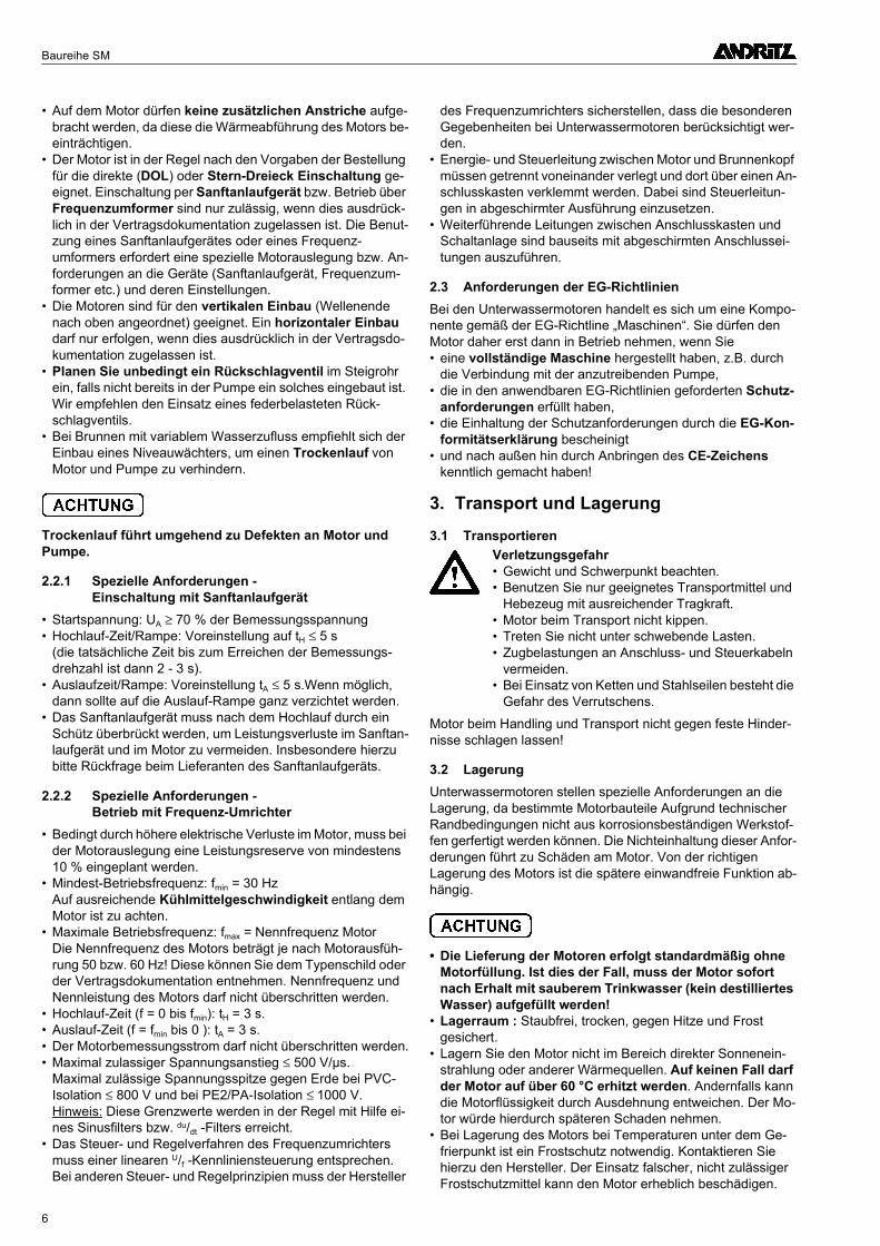
2.1.4 Kühlmitteltemperatur und GeschwindigkeitIm Betrieb wird die Motorbetriebswärme über den Motormantel und eventuell angebaute Wärmetauscher an das umfließende Medium abgegeben.Abhängig von Fließgeschwindigkeit und den zu erwartenden Ablagerungen am Motormantel, darf die für diese Einsatzbe-dingung festgelegte maximale Kühlmitteltemperatur nicht überschritten werden, um eine optimale Kühlung zu gewährlei-sten.Angaben zu diesen Werten finden Sie in der Regel in der bei-liegenden Vertragsdokumentation.Für Standardmotoren finden Sie im Anhang dieser Anleitung Richtwerttabellen für die maximal zulässigen Kühlmitteltem-peraturen in Abhängigkeit verschiedener Einsatzbedingun-gen.Empfohlen wird eine Kühlmittelgeschwindigkeit von minde-stens > 0,5 m/s entlang dem Motor.Sollten die erforderlichen Informationen nicht gefunden wer-den, oder Unklarheiten bestehen, so wenden Sie sich bitte an den Motorhersteller.
Der Einsatz bei höheren Mediumtemperaturen oder niedri-geren Fließgeschwindigkeiten ist nur nach Rückfrage mit dem Hersteller oder bei ausdrücklichem Vermerk in der Vertragsdokumentation zulässig. Andernfalls kann dies zur Überhitzung und Beschädigung des Motors führen.
2.1.5 KühlmantelKann die geforderte minimale Geschwindigkeit des Kühlmittels nicht erreicht werden, z.B. wenn die Einlassöffnung des Brun-nens oberhalb des Motors liegt oder es sich um einen Brunnen mit großem Durchmesser handelt, ist ein Kühlmantel erforder-
lich. Dieser sollte den Motor komplett und die Wassereintritts-öffnung der Pumpe derart umschließen, dass eine Zwangskühlung des Motors erfolgt (siehe Bild 1).
Die Kühlmittelgeschwindigkeit ergibt sich aus dem Brunnen-durchmesser und der Fördermenge der Pumpe.
Berechnung der Fließgeschwindigkeit:
V = Fließgeschwindigkeit Q = Fördermenge [m³/h] D = Brunnendurchmesser [mm] d = Motordurchmesser [mm]
2.2 Anforderungen beim Einsatz• Die maximale Eintauchtiefe unterhalb des Wasserspiegels
darf 350 m nicht überschreiten.• Größere Eintauchtiefen auf Anfrage.• Die maximal zulässige Schalthäufigkeit des Motors darf
nicht überschritten werden. Vor dem erneuten Einschalten ist eine festgelegte Schaltpause einzuhalten . Ansonsten er-folgt eine Überhitzung und Beschädigung der Wicklung! Die folgende Tabelle zeigt die geltenden Werte für Schalt-häufigkeiten und Schaltpausen:
• Die Abführung der Motorbetriebswärme an das Förderme-dium erfolgt über die Motoroberfläche. Der Einsatz in Medien, bei denen die Gefahr von Ablagerungen besteht, ist nur zu-lässig, wenn dies in der Vertragsdokumentation berücksich-tigt ist.
Bild 1: Kühlmantel
TypSchalthäufigkeit
[Schaltungenpro h]
Stillstandszeit[min]
SM8 15 2
SM8T, SM8F, SM8FT
10 2
SM9, SM9T, SM9F, SM9FT
8 3
SM10, SM10T, SM10F, SM10FT
8 3
SM12, SM12T, SM12F, SM12FT
8 3
SM14, SM14T, SM14F, SM14FT
4 5
Tabelle 1: Schalthäufigkeiten und Stillstandszeiten
[ ]VQ x
D dm s=
-
353 682 2
,/
5
Baureihe SM
• Auf dem Motor dürfen keine zusätzlichen Anstriche aufge-bracht werden, da diese die Wärmeabführung des Motors be-einträchtigen.
• Der Motor ist in der Regel nach den Vorgaben der Bestellung für die direkte (DOL) oder Stern-Dreieck Einschaltung ge-eignet. Einschaltung per Sanftanlaufgerät bzw. Betrieb über Frequenzumformer sind nur zulässig, wenn dies ausdrück-lich in der Vertragsdokumentation zugelassen ist. Die Benut-zung eines Sanftanlaufgerätes oder eines Frequenz-umformers erfordert eine spezielle Motorauslegung bzw. An-forderungen an die Geräte (Sanftanlaufgerät, Frequenzum-former etc.) und deren Einstellungen.
• Die Motoren sind für den vertikalen Einbau (Wellenende nach oben angeordnet) geeignet. Ein horizontaler Einbau darf nur erfolgen, wenn dies ausdrücklich in der Vertragsdo-kumentation zugelassen ist.
• Planen Sie unbedingt ein Rückschlagventil im Steigrohr ein, falls nicht bereits in der Pumpe ein solches eingebaut ist. Wir empfehlen den Einsatz eines federbelasteten Rück-schlagventils.
• Bei Brunnen mit variablem Wasserzufluss empfiehlt sich der Einbau eines Niveauwächters, um einen Trockenlauf von Motor und Pumpe zu verhindern.
Trockenlauf führt umgehend zu Defekten an Motor und Pumpe.
2.2.1 Spezielle Anforderungen - Einschaltung mit Sanftanlaufgerät
• Startspannung: UA ≥ 70 % der Bemessungsspannung• Hochlauf-Zeit/Rampe: Voreinstellung auf tH ≤ 5 s
(die tatsächliche Zeit bis zum Erreichen der Bemessungs-drehzahl ist dann 2 - 3 s).
• Auslaufzeit/Rampe: Voreinstellung tA ≤ 5 s.Wenn möglich, dann sollte auf die Auslauf-Rampe ganz verzichtet werden.
• Das Sanftanlaufgerät muss nach dem Hochlauf durch ein Schütz überbrückt werden, um Leistungsverluste im Sanftan-laufgerät und im Motor zu vermeiden. Insbesondere hierzu bitte Rückfrage beim Lieferanten des Sanftanlaufgeräts.
2.2.2 Spezielle Anforderungen - Betrieb mit Frequenz-Umrichter
• Bedingt durch höhere elektrische Verluste im Motor, muss bei der Motorauslegung eine Leistungsreserve von mindestens 10 % eingeplant werden.
• Mindest-Betriebsfrequenz: fmin = 30 Hz Auf ausreichende Kühlmittelgeschwindigkeit entlang dem Motor ist zu achten.
• Maximale Betriebsfrequenz: fmax = Nennfrequenz Motor Die Nennfrequenz des Motors beträgt je nach Motorausfüh-rung 50 bzw. 60 Hz! Diese können Sie dem Typenschild oder der Vertragsdokumentation entnehmen. Nennfrequenz und Nennleistung des Motors darf nicht überschritten werden.
• Hochlauf-Zeit (f = 0 bis fmin): tH = 3 s.• Auslauf-Zeit (f = fmin bis 0 ): tA = 3 s.• Der Motorbemessungsstrom darf nicht überschritten werden.• Maximal zulassiger Spannungsanstieg ≤ 500 V/µs.
Maximal zulässige Spannungsspitze gegen Erde bei PVC-Isolation ≤ 800 V und bei PE2/PA-Isolation ≤ 1000 V. Hinweis: Diese Grenzwerte werden in der Regel mit Hilfe ei-nes Sinusfilters bzw. du/dt -Filters erreicht.
• Das Steuer- und Regelverfahren des Frequenzumrichters muss einer linearen U/f -Kennliniensteuerung entsprechen. Bei anderen Steuer- und Regelprinzipien muss der Hersteller
des Frequenzumrichters sicherstellen, dass die besonderen Gegebenheiten bei Unterwassermotoren berücksichtigt wer-den.
• Energie- und Steuerleitung zwischen Motor und Brunnenkopf müssen getrennt voneinander verlegt und dort über einen An-schlusskasten verklemmt werden. Dabei sind Steuerleitun-gen in abgeschirmter Ausführung einzusetzen.
• Weiterführende Leitungen zwischen Anschlusskasten und Schaltanlage sind bauseits mit abgeschirmten Anschlussei-tungen auszuführen.
2.3 Anforderungen der EG-RichtlinienBei den Unterwassermotoren handelt es sich um eine Kompo-nente gemäß der EG-Richtline „Maschinen“. Sie dürfen den Motor daher erst dann in Betrieb nehmen, wenn Sie• eine vollständige Maschine hergestellt haben, z.B. durch
die Verbindung mit der anzutreibenden Pumpe,• die in den anwendbaren EG-Richtlinien geforderten Schutz-
anforderungen erfüllt haben,• die Einhaltung der Schutzanforderungen durch die EG-Kon-
formitätserklärung bescheinigt• und nach außen hin durch Anbringen des CE-Zeichens
kenntlich gemacht haben!
3. Transport und Lagerung
3.1 Transportieren
Motor beim Handling und Transport nicht gegen feste Hinder-nisse schlagen lassen!
3.2 LagerungUnterwassermotoren stellen spezielle Anforderungen an die Lagerung, da bestimmte Motorbauteile Aufgrund technischer Randbedingungen nicht aus korrosionsbeständigen Werkstof-fen gerfertigt werden können. Die Nichteinhaltung dieser Anfor-derungen führt zu Schäden am Motor. Von der richtigen Lagerung des Motors ist die spätere einwandfreie Funktion ab-hängig.
• Die Lieferung der Motoren erfolgt standardmäßig ohne Motorfüllung. Ist dies der Fall, muss der Motor sofort nach Erhalt mit sauberem Trinkwasser (kein destilliertes Wasser) aufgefüllt werden!
• Lagerraum : Staubfrei, trocken, gegen Hitze und Frost gesichert.
• Lagern Sie den Motor nicht im Bereich direkter Sonnenein-strahlung oder anderer Wärmequellen. Auf keinen Fall darf der Motor auf über 60 °C erhitzt werden. Andernfalls kann die Motorflüssigkeit durch Ausdehnung entweichen. Der Mo-tor würde hierdurch späteren Schaden nehmen.
• Bei Lagerung des Motors bei Temperaturen unter dem Ge-frierpunkt ist ein Frostschutz notwendig. Kontaktieren Sie hierzu den Hersteller. Der Einsatz falscher, nicht zulässiger Frostschutzmittel kann den Motor erheblich beschädigen.
Verletzungsgefahr• Gewicht und Schwerpunkt beachten.• Benutzen Sie nur geeignetes Transportmittel und
Hebezeug mit ausreichender Tragkraft.• Motor beim Transport nicht kippen.• Treten Sie nicht unter schwebende Lasten.• Zugbelastungen an Anschluss- und Steuerkabeln
vermeiden.• Bei Einsatz von Ketten und Stahlseilen besteht die
Gefahr des Verrutschens.
6
Baureihe SM
DE
UT
SC
H
• Motor stehend (Wellenende nach oben) lagern! Sorgen Sie bei stehender Lagerung dafür, dass der Motor nicht umfallen kann.
• Monatlich Motorwelle drehen. Lage der Welle zum vorherge-henden Zustand verändern.
3.3 AuspackenLieferung auf Vollständigkeit und Unversehrtheit überprüfen. Lassen Sie festgestellte Mängel vom Transportunternehmen auf dem Orginal-Frachtbrief bestätigen und unterrichten Sie uns unverzüglich darüber.
3.4 Erste ÜberprüfungPrüfen Sie nach dem Auspacken, ob äußerlich Beschädigun-gen sichtbar sind, zum Beispiel• am Gehäuseboden• am Gehäuse (Stator)• an der oberen und unteren Gehäusekappe (Motorlager)• am Anschluss- oder Steuerkabel
4. Motor montieren
4.1 Benötigtes WerkzeugFür die erforderlichen Überprüfungen und eine einwandfreie Montage benötigen Sie folgende Werkzeuge und Instrumente:• Isolationsmessgerät mit 500 Volt Prüfspannung bzw. 5000
Volt Prüfspannung für Hochspannungsmotoren mit mehr als 3000 Volt Betriebsspannung. Anzeige bis mindestens 200 MOhm.
• Geeignetes Werkzeug für die Befüllung und den Zusammen-bau des Motors (Wasserbehälter, Trichter, Schraubenschlüs-sel, Drehmomentschlüssel etc.).
4.2 Auffüllen des Motors
• Vor der Installation muss der Motor mit sauberem Trink-wasser (kein destilliertes Wasser) aufgefüllt werden.
• Wurde der Motor mit Motorfüllung geliefert oder bereits zur Lagerung gefüllt, muss die Motorfüllung vor der In-stallation kontrolliert werden. Wenn die Prüfung ergeben hat, dass Motorflüssigkeit fehlt, können Sie sauberes Trinkwasser (kein destilliertes Wasser) nachfüllen.
• Verwenden Sie bitte Füllwasser mit einem PH-Wert zwischen 7 und 7,5, sowie 7...8 deutschem Härtegrad, 10-20mg/l Nitrat. Schwebstoffe und Sand dürfen nicht enthalten sein. Passen-de Messgeräte sind auf Anfrage erhältlich.
• Für die Lagerung konservierte bzw. mit Frostschutz gefüllte Motoren müssen vor dem Einsatz in Trinkwasser entleert, ge-spült, gereinigt und anschließend wieder mit sauberem Trink-wasser gefüllt werden.
4.2.1 Motorflüssigkeit einfüllen
• Motor in senkrechte Lage bringen.• Der Motor ist grundsätzlich in senkrechter Lage aufzufüllen!• Verschlussschraube der Auffüll- und Entlüftungsöffnung
entfernen.• Trichter (Winkeltrichter) in die Auffüllöffnung einsetzen.• Motor über Trichter mit Wasser drucklos befüllen, bis das
Wasser aus der Füllöffnung tritt.• Füllstand nach 2 Stunden Wartezeit erneut kontrollieren. Der
Füllvorgang ist solange durchzuführen, bis das Wasser in der Auffüll- und Entlüftungsöffnung blasenfrei stehen bleibt.
• Verschlussschraube mit Dichtung sind wieder dicht einzudrehen.
4.3 Zusammenbau von Motor und Pumpe (Aggregat)
4.3.1 Vorbereitende Prüfungen• Entfernen Sie ggf. den Wellenschutz.• Drehen Sie die Motorwelle vor dem Zusammenbau mit der
Hand oder mit einem Hilfswerkzeug durch. Es darf nur geeig-netes Hilfswerkzeug eingesetzt werden um mechanische Be-schädiungen an der Welle zu verhindern. Die Welle muss nach Überwindung der Haftreibung frei laufen. Falls nicht, muss die Ursache ermittelt werden.
• Achten Sie darauf, dass die Oberflächen der zu verbindenden Teile schmutz- und staubfrei sind.
4.3.2 Zusammenbau
4.3.2.1 Motoren mit NEMA-Kupplung (SM8, SM9)• Bestreichen Sie das Innenteil der Kupplung mit einem was-
serfesten, säurefreien Fett (z.B. Mobil FM 102, Texaco Cyg-nus 2661, Gleitmo 746). Das Fett minimiert die Reibung und bietet einen zusätzlichen Schutz gegen das Eindringen von Sand.
• Achten Sie beim Zusammenfügen von Motor und Pumpe dar-auf, dass die Verzahnung durch einen O-Ring umfasst wird. Dieser O-Ring verhindert ein Eindringen von Sand und Schmutz in die Wellenverzahnung.
• Richten Sie die Pumpen- und Motorwelle gegeneinander aus, und führen Sie Pumpe und Motor zusammen.
• Die Pumpen- und Motorwellen dürfen keine starre Verbin-dung (Kupplung) in Axialrichtung haben.
• Die Kupplung soll auf der Pumpenwelle befestigt sein und auf der Motorwelle gleiten.
• Benutzen Sie nur Befestigungschrauben der entsprechenden Güteklasse und Abmessungen, die vom Pumpenhersteller vorgeschrieben und zugelassen sind.
• Halten Sie die vom Pumpenhersteller vorgeschriebenen An-zugsdrehmomente ein.
• Verschrauben Sie den Motor mit dem Aggregat und ziehen Sie die Befestigungsschrauben vorschriftsmäßig über Kreuz an.
Verletzungsgefahr• Nehmen Sie den Motor vorsichtig aus der Verpak-
kung, um Schäden zu vermeiden.• Gewicht und Schwerpunkt beachten.• Benutzen Sie nur geeignetes Hebezeug mit aus-
reichender Tragkraft.• Treten Sie nicht unter schwebende Lasten.• Schützen Sie die Motorkabel vor mechanischer
Einwirkung.
Wenn Sie Schäden feststellen, dürfen Sie den Motor nicht montieren oder in Betrieb nehmen. Bei be-schädigtem Motor besteht Verletzungs- und Lebensgefahr.
Verletzungsgefahr!Sorgen Sie dafür, dass der Motor während des Vor-gangs nicht umfallen kann.
Verwenden Sie den Motor niemals mit beschä-digten Pumpen oder Teilen. Wegen der hohen Antriebskräfte kann es anderenfalls zu Unfällen kommen. Es besteht Verletzungs- und Lebens-gefahr!
7
Baureihe SM
4.3.2.2 Motoren mit Wellenkupplung (SM10, SM12, SM14)
Die Montage von Motor und Pumpe erfordert spezielle Kennt-nisse über die Einstellung der Pumpe und sollte entsprechend den Anforderungen der Pumpe vorgenommen werden.Bei der Montage ist auf ausreichende Dimensionierung der Verbindungselemente und Freigängigkeit des Rotors zu ach-ten.
4.3.3 Abschließende PrüfungenSollte die Kupplungsstelle beim Betrieb frei zugänglich sein, müssen Sie diese unbedingt gegen Berührung schützen!
4.4 Motorkabel anschließen
• Das Kabel darf auf keinen Fall scharfe Kanten berühren können.
• Verlegen Sie das Kabel entlang der Pumpe und schützen Sie es vor Beschädigungen mit der Kabelschutzschiene. Beach-ten Sie hierzu auch die Angaben des Pumpenherstellers.
4.4.1 Anschluss des Erdleiters
• Prüfen Sie ob die Motoren mit Erdleiter ausgeliefert wurden. Dies hängt von der bestellten Anschlussvariante des Motors ab.
• Bauseits ist für den fachgerechten Anschluss eines Erdleiters zu sorgen. Besitzt der Motor keinen Erdleiter so ist an der oberen Gehäusekappe des Motors eine entsprechende Er-dungsklemme vorhanden, an der ein seperater Erdleiter fach-gerecht angeschlossen werden muss.
4.4.2 Motorkabel verlängernDas mitgelieferte Motorkabel kann bauseits verlängert werden. Verwenden Sie hierzu nur Verlängerungskabel
- deren Material für den Einsatz geeignet sind.- die für in Ihrem Medium auftretenden Temperaturen zuge-
lassen sind.- die einen für die Bedingungen (Leistung, Kabellänge, etc.)
ausreichenden Querschnitt aufweisen.• Achten Sie bei der Auswahl des Kabels sowohl auf eine ent-
sprechende Spannungsfestigkeit, als auch auf die Eignung für das Medium (insbesondere bei Trinkwasser). Prüfen Sie bei der Auswahl den Spannungsabfall auf dem Kabel um die Vorgaben der Toleranzen der Versorgungsspannung am Mo-tor einzuhalten! Nichtbeachtung kann eine Beschädigung des Motors durch Überhitzung hervorrufen.
• Für die richtige Auswahl und Dimensionierung des Kabels ist der Installateur verantwortlich!
• Schützen Sie die Verbindungsstelle der Kabel gegen das Ein-dringen von Wasser. Hierfür sind am Markt Schrumpf-schläuche, Vergussmassen oder fertige Kabelgarnituren erhältlich.
• Beachten Sie die Anleitung des jeweiligen Lieferanten über den Umgang mit dem Isoliermaterial.
• Das Kabel ist an jeder Steigrohrleitung mit Kabelbändern oder Kabelschellen sorgfältig zu befestigen. Je nach Größe und Schwere des Kabels muss die Befestigung mindestens in 3 m Abstand oder kürzer erfolgen. Das Kabel darf keiner Zugbelastung ausgesetzt werden.
• Beachten Sie in diesem Zusammenhang auch die Hinweise des Pumpenherstellers.
4.4.3 Isolationswiderstand messenFühren Sie diese Messung durch, bevor und während das fertig montierte Aggregat am Einsatzort abgesenkt wird.• Verbinden Sie das eine Messkabel mit dem Erdleiter während
dem Absenken.• Das andere Messkabel verbinden Sie nun nacheinander mit
jeder Ader des angeschlossenen Motorkabels - jedoch nicht mit dem Erdleiter.
• Achten Sie darauf, dass die Kontaktstellen sauber sind.• Der Motor ist in Ordnung, wenn der Isolationswiderstand den
Wert in der nachfolgenden Tabelle nicht unterscheitet. Für eine korrekte Messung muss der Motor vollständig sein.
5. Elektrischer Anschluss
5.1 VoraussetzungenDieses Kapitel setzt voraus, dass• der Motor ordnungsgemäß mit der Pumpe zusammenge-
baut ist, wie im Kapitel 4 beschrieben.• der Isolationswiderstand gemessen und für einwandfrei be-
funden wurde, wie im Kapitel 4 beschrieben.• das fertigmontierte Aggregat ordnungsgemäß am Einsatzort
installiert ist, wie in der Anleitung des Pumpenherstellers be-schrieben.
5.2 EnergieversorgungDie Energieversorgung muss mindestens den folgenden Anfor-derungen entsprechen, um Schäden am Motor und uner-wünschte Netzrückwirkungen zu vermeiden.
• Das Kabel ist beim Einbau (und auch beim Ziehen des Aggregates) sorgfältig aufgerollt oder ausge-legt zu lagern, damit bei einem evtl. Absturz der Pumpe in den Brunnenschacht keine Personen- oder Sachschäden, durch das zwangsläufig mitge-rissene Kabel, auftreten können.
• Es ist darauf zu achten, dass keine Personen in die aufgerollte Kabelspirale treten.
Motorzustand Spannung> 1000 Volt
Neuer Motor 500 MOhm
Installierter / Reparierter Motor 200 MOhm
Tabelle 2: Isolationswiderstände
Zu Ihrer Sicherheit!• Arbeiten am elektrischen System dürfen nur von
qualifizierten Fachkäften durchgeführt werden.• Bevor Sie irgendwelche Anschlussarbeiten aus-
führen, stellen Sie unbedingt erst sicher, dass auf der gesamten Anlage keinerlei elektrische Spannung anliegt und niemand versehentlich die Spannung wieder einschalten kann, während an der Anlage noch gearbeitet wird.
• Arbeiten Sie niemals an elektrischen Anlagen, während ein Gewitter aufzieht oder stattfindet. Durch Blitzschlag können gefährliche Überspan-nungen auftreten.
• Wenn Sie diese Hinweise nicht beachten, be-steht akute Lebensgefahr durch einen elektri-schen Schlag.
8
Baureihe SM
DE
UT
SC
H
5.2.1 Energieversorgung durch NetzanschlussFolgende Toleranzen dürfen nicht überschritten werden, da sonst der Motor beschädigt werden kann:• Die Spannungstoleranz muss insgesamt in einem Bereich
von -10% bis +6% von der Nennspannung liegen (an den Mo-torklemmen gemessen).
• Die Abweichung eines Motorstromes vom Mittelwert aller drei Ströme darf max. 10% nicht überschreiten.
• Im Betrieb darf der Mittelwert aller 3 Phasenströme den Nennstrom des Motors nicht überschreiten.
5.3 Motor anschließen• Beachten Sie hierzu auch die Angaben auf dem Typenschild
am Motor und dimensionieren Sie danach die elektrische An-lage.
• Die folgenden Anschlussbeispiele beziehen sich ausschließ-lich auf den Motor selber - sie sind keine Empfehlung hin-sichtlich der vorgeschalteten Steuerelemente!
• Für eine fachlich einwandfreie Planung und Ausführung der Installation ist der Installateur verantwortlich.
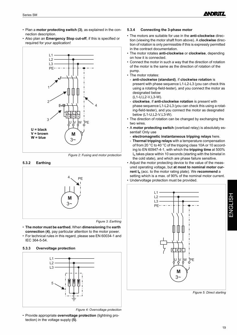
5.3.1 Absicherung und Motorschutz• Planen Sie einen externen Netzschalter (1) ein, um die An-
lage jederzeit spannungsfrei schalten zu können - zum Bei-spiel bei Gefahr oder bei Arbeiten an der Anlage.
• Planen Sie bauseits Sicherungen (2) für jede einzelne Phase ein.
• Planen Sie einen Motorschutzschalter (3) ein, wie in der An-schlussbeschreibung erläutert.
• Planen Sie auch eine Not-Aus-Abschaltung ein, soweit dies für Ihren Verwendungszweck vorgeschrieben oder erforder-lich ist!
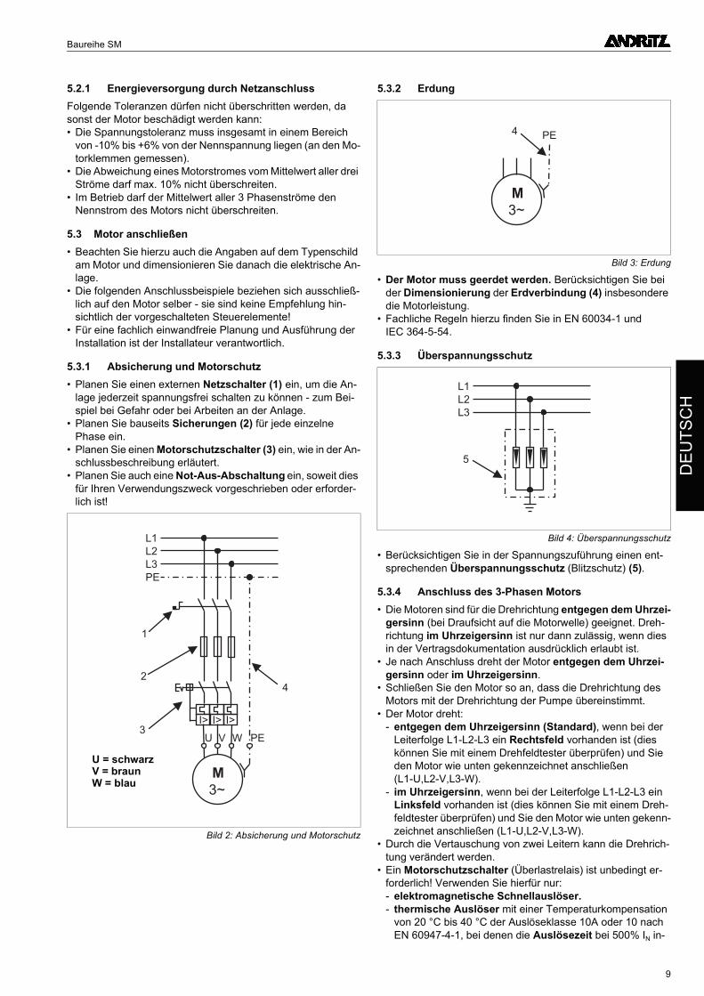
5.3.2 Erdung
• Der Motor muss geerdet werden. Berücksichtigen Sie bei der Dimensionierung der Erdverbindung (4) insbesondere die Motorleistung.
• Fachliche Regeln hierzu finden Sie in EN 60034-1 und IEC 364-5-54.
5.3.3 Überspannungsschutz
• Berücksichtigen Sie in der Spannungszuführung einen ent-sprechenden Überspannungsschutz (Blitzschutz) (5).
5.3.4 Anschluss des 3-Phasen Motors• Die Motoren sind für die Drehrichtung entgegen dem Uhrzei-
gersinn (bei Draufsicht auf die Motorwelle) geeignet. Dreh-richtung im Uhrzeigersinn ist nur dann zulässig, wenn dies in der Vertragsdokumentation ausdrücklich erlaubt ist.
• Je nach Anschluss dreht der Motor entgegen dem Uhrzei-gersinn oder im Uhrzeigersinn.
• Schließen Sie den Motor so an, dass die Drehrichtung des Motors mit der Drehrichtung der Pumpe übereinstimmt.
• Der Motor dreht:- entgegen dem Uhrzeigersinn (Standard), wenn bei der
Leiterfolge L1-L2-L3 ein Rechtsfeld vorhanden ist (dies können Sie mit einem Drehfeldtester überprüfen) und Sie den Motor wie unten gekennzeichnet anschließen (L1-U,L2-V,L3-W).
- im Uhrzeigersinn, wenn bei der Leiterfolge L1-L2-L3 ein Linksfeld vorhanden ist (dies können Sie mit einem Dreh-feldtester überprüfen) und Sie den Motor wie unten gekenn-zeichnet anschließen (L1-U,L2-V,L3-W).
• Durch die Vertauschung von zwei Leitern kann die Drehrich-tung verändert werden.
• Ein Motorschutzschalter (Überlastrelais) ist unbedingt er-forderlich! Verwenden Sie hierfür nur:- elektromagnetische Schnellauslöser.- thermische Auslöser mit einer Temperaturkompensation
von 20 °C bis 40 °C der Auslöseklasse 10A oder 10 nach EN 60947-4-1, bei denen die Auslösezeit bei 500% IN in-
Bild 2: Absicherung und Motorschutz
M
3~
I>
L1
L2
L3
PE
2
3
4
1
I> I>
U V W PE
U = schwarzV = braunW = blau
Bild 3: Erdung
Bild 4: Überspannungsschutz
M
3~
PE4
L1
L2
L3
5
9
Baureihe SM
nerhalb von 10 Sekunden erfolgt (ausgehend vom kalten Zustand der Bimetalle), und die phasenausfallempfindlich sind.
• Stellen Sie das Motorschutzgerät auf den Wert des gemesse-nen Betriebsstromes ein, jedoch maximal auf Motornenn-strom IN (gem. Motortypenschild). Wir empfehlen eine Einstellung auf max. 90% des Motornennstromes.
• Ein Unterspannungsschutz ist vorzusehen.
5.3.5 Thermische Überwachung• Bei thermischer Überwachung mit Temperatursensoren
PT100 ist das passende Auslösegerät zu verwenden.• Bei Motoren für Frequenzumrichterbetrieb müssen Steuerlei-
tungen in abgeschirmter Ausführung eingesetzt werden. Der Schirm ist dabei auf beiden Kabelenden auf Masse zu legen.
• Um Messfehler bei langen Leitungswegen zu vermeiden, müssen bei einer Kabellänge größer 50 Meter Ausgleichslei-tungen eingesetzt werden. Ein geeignetes Auslösegerät mit 3-Leiterkompensation ist zu verwenden. Anschlusspläne für PT100 mit Ausgleichsleitungen finden Sie im Anhang dieser Anleitung.
6. Inbetriebnahme
6.1 VoraussetzungenDieses Kapitel setzt voraus, dass• der Motor ordnungsgemäß mit der Pumpe zusammenge-
baut ist, wie im Kapitel 4 beschrieben.• der Isolationswiderstand gemessen und für einwandfrei be-
funden wurde, wie im Kapitel 4 beschrieben.• das fertigmontierte Aggregat ordnungsgemäß am Einsatzort
installiert ist, wie in der Anleitung des Pumpenherstellers be-schrieben.
• der Motor ordnungsgemäß angeschlossen und abgesi-chert ist, wie im Kapitel 5 beschrieben.
6.2 Prüfung vor der InbetriebnahmeBevor Sie den Motor in Betrieb nehmen stellen Sie unbedingt erst sicher, dass• der Motor vollständig untergetaucht ist. Der Motor darf nur
unter Wasser betrieben werden.• das Steigrohr entlüftet ist, um Wasserschläge beim Anlau-
fen zu vermeiden. Andernfalls können sowohl das Aggregat als auch die Förderleitungen beschädigt werden.
• die vom Pumpenhersteller geforderten Bedingungen zur In-betriebnahme erfüllt sind.
• alle elektrischen Anschlüsse und Schutzeinrichtungen über-prüft und Absicherungen ordnungsgemäß eingestellt sind.
• keine Gefahrenstellen mehr frei zugänglich sind, insbe-sondere keine drehenden Teile, Ansaugstellen oder Druck-ausgänge sowie elektrische Anschlüsse.
• die Medientemperatur bei Motoren mit Wasserfüllung nicht unter 0 °C sinkt.
Andernfalls dürfen Sie den Motor nicht in Betrieb nehmen, weil Unfallgefahr besteht und der Motor beschädigt werden kann!
6.3 Motor einschaltenWenn Sie alle vorstehend genannten Punkte überprüft und de-ren Einhaltung sichergestellt haben, können Sie nun den Motor einschalten.Messen Sie sofort nach dem Einschalten:• den Betriebsstrom des Motors in jeder Phase.• die Netzspannung bei laufendem Motor.• den Stand des zu fördernden Mediums.Schalten Sie den Motor sofort ab, wenn• eine Überschreitung des Nennstroms gemäß der Angaben
auf dem Leistungsschild eintritt.• Spannungstoleranzen von mehr als +6%/-10% gegenüber
der Nennspannung gemessen werden. Bei schwachen Ver-sorgungsnetzen empfehlen wir den Einbau eines Span-nungswächters!
• ein Trockenlaufen droht. Bei unregelmäßigem Zulauf wird der Einbau eines Niveauwächters erforderlich, um einen Trockenlauf zu verhindern.
• Die Abweichung eines Motorstromes vom Mittelwert aller drei Ströme größer als 10% beträgt.
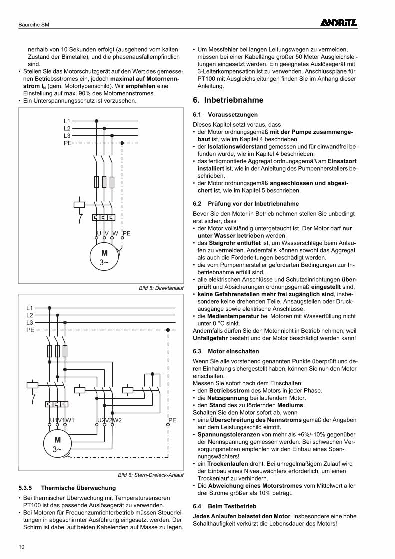
6.4 Beim TestbetriebJedes Anlaufen belastet den Motor. Insbesondere eine hohe Schalthäufigkeit verkürzt die Lebensdauer des Motors!
Bild 5: Direktanlauf
Bild 6: Stern-Dreieck-Anlauf
M
3~
L1
L2
L3
PE
U V W PE
M
3~
L1
L2
L3
PE
U1V1W1 PEU2V2W2
10
Baureihe SM
DE
UT
SC
H
Stellen Sie daher sicher, dass auch beim Testbetrieb die unter Punkt 2.2 angegebenen Werte zur Schalthäufigkeit nicht überschritten werden. Auch die zugehörige Stillstandszeit ist einzuhalten!Es ist sicherzustellen, dass durch die Schaltanlage keine Flat-terschaltungen auftreten können.
7. Wartung• Unterwassermotoren sind wartungsfrei.• Um Funktionsstörungen durch Ablagerungen zu vermeiden
sollte der Motor im Brunnen mindestens einmal pro Woche für 5 Minuten in Betrieb genommen werden. Der Motor muss dabei vollständig untergetaucht sein.
• Wir empfehlen zur rechtzeitigen Erkennung von Funktions-störungen die Durchführung und Protokollierung der folgen-den Tests:- Versorgungsspannung- Stromaufnahme- Isolationsmessung- Betriebsstunden- Vorgaben des Pumpenherstellers (Fördermenge, Förder-
druck etc.)Die Stromaufnahme ist der wichtigste Wert für die Funktions-überwachung des Motors. Bei größeren Abweichungen in der Stromaufnahme vom Sollwert muss die Ursache ermittelt werden. Eine zu hohe Stromaufnahme ist schädlich für den Motor!
8. Störungen : Ursachen und Beseitigung
8.1 Allgemein
• Nehmen Sie keine anderen Arbeiten am Motor vor, außer den hier beschriebenen. Andernfalls kann der Motor be-schädigt werden und die Betriebssicherheit der Anlage ist nicht mehr gewährleistet. Wegen der zum Teil sehr hohen Antriebs- und Förderkräfte können erhebliche Unfallgefah-ren entstehen. Es besteht auch Lebensgefahr durch einen elektrischen Schlag.
• Zur Störungssuche und -behebung an der ganzen Anlage be-achten Sie unbedingt auch die entsprechenden Hinweise in der Anleitung des Pumpenherstellers!
• Führen Sie keinerlei Veränderungen oder Umbauten am Motor oder dessen elektrischen Anschlüssen durch. An-dernfalls ist die Sicherheit des Motors nicht mehr gewährlei-stet.
• Arbeiten Sie nur im Stillstand! Es sind keinerlei Arbeiten oder Kontrollen während des laufenden Betriebs erforderlich.
• Arbeiten am elektrischen System dürfen nur von qualifizierten Fachkäften durchgeführt werden.
• Schalten Sie die Anlage spannungsfrei, bevor Sie die hier beschriebenen Arbeiten ausführen.
• Stellen Sie sicher, dass niemand versehentlich die Span-nung wieder einschalten kann, während an der Anlage noch gearbeitet wird!
• Arbeiten Sie niemals an elektrischen Anlagen, wenn ein Ge-witter aufzieht oder stattfindet.
• Sorgen Sie dafür, dass unmittelbar nach Beendigung der Ar-beiten alle Sicherheits- und Schutzeinrichtungen wieder vollständig angebracht und in Funktion gesetzt werden.
8.2 Elektrische StörungenBei elektrischen Störungen wie zum Beispiel wiederholten Ab-schaltungen sollten Sie den Isolationswiderstand vom Fach-mann überprüfen lassen.• Trennen Sie das Motoranschlusskabel von der Anlage und
messen Sie Motor und Kabel zunächst gemeinsam. Wenn der Isolationswiderstand deutlich geringer als der Sollwert un-ter Punkt 4.4.3 ist, müssen Sie die Messung einzeln für das Kabel und den Motor wiederholen. Hierzu trennen Sie das Kabel ungefähr einen Meter vor dem Motor ab.
• Liegt es am Kabel? Dann schließen Sie ein neues Kabel an.• Liegt es am Motor? Dann müssen Sie diesen vom Hersteller
oder einer autorisierten Fachwerkstatt instandsetzen lassen. Alternativ kann ein neuer Motor eingesetzt werden.
• Liegt es weder am Motor, noch am Kabel? Dann sollten Sie die elektrische Anlage prüfen lassen.
8.3 Mechanische oder hydraulische StörungenBei mechanischen oder hydraulischen Störungen wie zum Bei-spiel ungewöhnlichen Geräuschen, Störungen im Rundlauf der Pumpe oder ein zu häufiges Ein- und Ausschalten der Pumpe ist die Störungsursache am Aggregat zu suchen.• Nehmen Sie hierzu die Anleitung des Pumpenherstellers zu
Hilfe, um die Ursache zu finden.
Zu Ihrer Sicherheit!Beachten Sie insbesondere die hier aufgeführten Si-cherheitshinweise. Anderenfalls besteht Unfall- und Lebensgefahr!
11
Baureihe SM
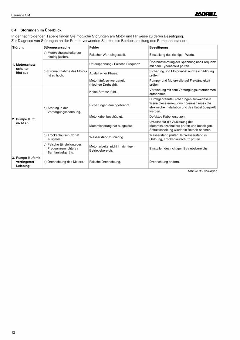
8.4 Störungen im ÜberblickIn der nachfolgenden Tabelle finden Sie mögliche Störungen am Motor und Hinweise zu deren Beseitigung. Zur Diagnose von Störungen an der Pumpe verwenden Sie bitte die Betriebsanleitung des Pumpenherstellers.
Störung Störungsursache Fehler Beseitigung
1. Motorschutz- schalter löst aus
a) Motorschutzschalter zu niedrig justiert.
Falscher Wert eingestellt. Einstellung des richtigen Werts.
b) Stromaufnahme des Motors ist zu hoch.
Unterspannung / Falsche Frequenz.Übereinstimmung der Spannung und Frequenz mit dem Typenschild prüfen.
Ausfall einer Phase.Sicherung und Motorkabel auf Beschädigung prüfen.
Motor läuft schwergängig (niedrige Drehzahl).
Pumpe- und Motorwelle auf Freigängigkeit prüfen.
2. Pumpe läuft nicht an
a) Störung in der Versorgungsspannung.
Keine Stromzufuhr.Verbindung mit dem Versorgungsunternehmen aufnehmen.
Sicherungen durchgebrannt.
Durchgebrannte Sicherungen auswechseln. Wenn diese erneut durchbrennen muss die elektrische Installation und das Kabel überprüft werden.
Motorkabel beschädigt. Defektes Kabel ersetzen.
Motorsicherung hat ausgelöst.Ursache für die Auslösung des Motorschutzschalters prüfen und beseitigen. Schutzschaltung wieder in Betrieb nehmen.
b) Trockenlaufschutz hat ausgelöst
Wasserstand zu niedrig.Wasserstand prüfen. Ist Wasserstand in Ordnung, Trockenlaufschutz prüfen.
c) Falsche Einstellung des Frequenzumrichters / Sanftanlaufgeräts.
Motor arbeitet nicht im richtigen Betriebsbereich.
Einstellen des richtigen Betriebsbereichs.
3. Pumpe läuft mit verringerter Leistung
a) Drehrichtung des Motors. Falsche Drehrichtung. Drehrichtung ändern.
Tabelle 3: Störungen
12
Series SM
EN
GL
ISH
Contents Page
1. General information ..............................................................................................................141.1 Introduction ........................................................................................................................................................................ 141.2 Designation ........................................................................................................................................................................ 141.3 Factory plate ...................................................................................................................................................................... 141.4 Safety instructions.............................................................................................................................................................. 14
2. Important - observe strictly ..................................................................................................142.1 Intended use ...................................................................................................................................................................... 142.2 Requirements for operation................................................................................................................................................ 152.3 Requirements of the EC Directives .................................................................................................................................... 16
3. Transport and storage ..........................................................................................................163.1 Transport............................................................................................................................................................................ 163.2 Storage............................................................................................................................................................................... 163.3 Unpacking .......................................................................................................................................................................... 173.4 Initial checks....................................................................................................................................................................... 17
4. Installing the motor ...............................................................................................................174.1 Required tools .................................................................................................................................................................... 174.2 Filling the motor.................................................................................................................................................................. 174.3 Assembling the motor and pump assembly ....................................................................................................................... 174.4 Connecting the motor cable ............................................................................................................................................... 17
5. Electrical connection ............................................................................................................185.1 Assumptions....................................................................................................................................................................... 185.2 Power supply...................................................................................................................................................................... 185.3 Connecting the motor......................................................................................................................................................... 18
6. Commissioning......................................................................................................................206.1 Assumptions....................................................................................................................................................................... 206.2 Checks before putting the motor into operation ................................................................................................................. 206.3 Switching the motor on....................................................................................................................................................... 206.4 In test operation ................................................................................................................................................................. 20
7. Maintenance...........................................................................................................................208.1 General .............................................................................................................................................................................. 208.2 Electrical faults ................................................................................................................................................................... 21
8. Faults: Causes and remedial action ....................................................................................208.1 General .............................................................................................................................................................................. 208.2 Electrical faults ................................................................................................................................................................... 218.3 Mechanical or hydraulic faults............................................................................................................................................ 218.4 Overview of faults............................................................................................................................................................... 22
9. Appendix ................................................................................................................................339.1 Guide value tables for coolant temperatures ..................................................................................................................... 339.2 Connection diagram PT100 with equalising line ................................................................................................................ 40
13
Series SM
1. General information
1.1 IntroductionWe congratulate you for choosing our submersible motors. With this motor you have acquired a high-quality product which has been developed based on many years of experience in the field of motor technology.The following instructions will assist you in commissioning and operating your motor. If you require any additional support, please contact us at our factory.To ensure a quick and trouble-free response, please always in-clude the motor's serial number with any queries. This number always has at least 5 digits, and can be found on the motor's rating plate and on the outside of the upper housing cover (up-per motor bearing).
1.2 Designation
1.3 Factory plateBefore installing the motor, we recommend copying thetechnical values on the factory plate into the following field. This way you will always have the most important information avail-able quickly, even after installation.
1.4 Safety instructions
• The motors may only be used if these instructions are followed exactly. Keep these instructions in a safe place so that they will be available if questions come up later.
• In addition to these operating instructions, also observe the separate "Safety instructions" manual, all of the in-structions in the contract documentation, and any infor-mation sheets and operating instructions for any other components included in the delivery (pump operating in-structions, etc.).
• Motors or assemblies that have come in contact with haz-ardous substances must be decontaminated before any work is performed. They must be decontaminated or clearly and conspicu-ously labelled before being sent back to the manufactur-er or to an authorised repair shop.
• All safety and protective equipment must be refitted and reactivated immediately after conclusion of the work.
• The operational safety of the supplied motor is only en-sured if the motor is used in accordance with the specifi-cations and limit values in the contract documentation (operating instructions, etc.). Never exceed the specified limit values.
2. Important - observe strictly
2.1 Intended useRewindable, water-filled submersible motors are suitable only for operation underwater. They are primarily used to drive pumps.
As standard, the motors are shipped in an unfilled state. In order to guarantee adequate lubrication and cooling of the motor, it must be ensured that the motor is filled and sub-merged in accordance with the manufacturer's instruc-tions before it is put into operation!
2.1.1 Typical areas of useTypical areas of use for pumps driven with submersible motors are:• Drinking water supply in cities and other municipalities.• Wells in waterworks.• Water drainage in civil engineering and mining.• Booster stations in industry
(with the pump in a pressure shroud).
2.1.2 Permissible mediaThe submersible motors may be used exclusively in pure, low viscosity media, such as drinking water and process water.
Example
Illustration : Factory plate
SM 8 T / 75 / 2
Series
Min. well diameter [inches]
Motor variant (optional)T = highly heat-resistant windingF = 60 Hz versionR = miningS = special version
Rated motor power P2 [kW]
Number of poles
Typ
Bj.
Nr. Rep.
U V
I A
P1 kW P2 kW
n min-1
cos
Hz
Iso~ IP
�
• The risk of electric shocks must be eliminated (in accordance with VDE regulations and the regulations of your power utility).
• Work on the electrical system may only be car-ried out by qualified specialists.
• The motor must be completely isolated from the electric power supply before any mainte-nance or repair work.
14
Series SM
EN
GL
ISH
As a general rule, the suitability and materials selection for the motors should be checked by the purchaser based on water analyses or chemical analyses. If desired, this can also be done in cooperation with the motor manufacturer. The purchaser bears responsibility for selecting the correct materials.
The motors may only be used in media explicitly approved in the contract documentation!
2.1.3 Impermissible mediaUnder no circumstances may the submersible motors be used in other media,• and especially not to pump air, explosive media or waste-
water.• Motors made of corrosion-resistant materials are available for
use in aggressive media. The purchaser bears responsibility for selecting the correct materials.
2.1.4 Coolant temperature and velocityThe heat generated during operation is transmitted through the motor shroud and any installed heat exchangers and into the surrounding media flow.Depending on the flow velocity and the expected sediments on the motor shroud, the maximum coolant temperature defined for that operating condition may not be exceeded. Oth-erwise optimal cooling cannot be ensured.Information on these values are generally provided in the sup-plied contract documentation.For standard motors, please see the appendix to these instruc-tions for guide value tables with the maximum permissible coolant temperatures depending on various operating condi-tions.The recommended coolant velocity is at least > 0.5 m/s along the motor.If you do not find the information you need, or if something is unclear, please consult the motor manufacturer.
Operation with higher media temperatures or lower flow velocities is only permitted after consultation with the manufacturer, or if it is explicitly noted in the contract doc-umentation. Otherwise this may lead to overheating and damage to the motor.
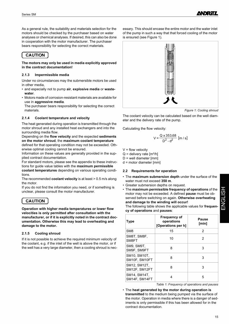
2.1.5 Cooling shroudIf it is not possible to achieve the required minimum velocity of the coolant, e.g. if the inlet of the well is above the motor, or if the well has a very large diameter, then a cooling shroud is nec-
essary. This should encase the entire motor and the water inlet of the pump in such a way that that forced cooling of the motor is ensured (see Figure 1).
The coolant velocity can be calculated based on the well diam-eter and the delivery rate of the pump.
Calculating the flow velocity:
V = flow velocity Q = delivery rate [m³/h] D = well diameter [mm] d = motor diameter [mm]
2.2 Requirements for operation• The maximum submersion depth under the surface of the
water must not exceed 350 m.• Greater submersion depths on request.• The maximum permissible frequency of operations of the
motor may not be exceeded. A defined pause must be ob-served before switching on again. Otherwise overheating and damage to the winding will occur! The following table shows the applicable values for frequen-cy of operations and pauses:
• The heat generated by the motor during operation is transmitted to the medium being pumped via the surface of the motor. Operation in media where there is a danger of sed-iments is only permissible if this has been allowed for in the contract documentation.
Figure 1: Cooling shroud
TypeFrequency of
operations[Operations per h]
Pause[min]
SM8 15 2
SM8T, SM8F, SM8FT
10 2
SM9, SM9T, SM9F, SM9FT
8 3
SM10, SM10T, SM10F, SM10FT
8 3
SM12, SM12T, SM12F, SM12FT
8 3
SM14, SM14T, SM14F, SM14FT
4 5
Table 1: Frequency of operations and pauses
[ ]VQ x
D dm s=
-
353 682 2
,/
15
Series SM
• No additional coatings may be applied to the motor, since they will compromise the heat transmission of the motor.
• According to the specifications in the order, the motor is gen-erally suitable for direct (DOL) or star-delta starting. Starting via a soft-start device or operation via a frequency convert-er are only permissible if this is explicitly approved in the con-tract documentation. The use of a soft-start device or a frequency converter requires a special motor rating or special requirements for the devices (soft-start device, frequency converter, etc.) and their settings.
• The motors are suitable for vertical installation (with the shaft end pointing upwards). Horizontal installation is only possible if this is explicitly approved in the contract documen-tation.
• If there is no check valve already integrated into the stand-pipe, be sure to provide one! We recommend using a spring-loaded check valve.
• In wells with a variable water influx, we recommend installing a level switch to keep the motor and pump from running dry.
Running dry will cause immediate damage to the motor and pump.
2.2.1 Special requirements - starting with a soft-start device
• Starting voltage: UA ≥ 70 % of the rated voltage• Acceleration time/ramp: preset to tH ≤ 5 s
(the actual time to reach the rated speed is then 2 - 3 s).• Deceleration time/ramp: Preset to tA ≤ 5 s. If possible, the de-
celeration ramp should be omitted completely.• After acceleration, the soft-start device should be bypassed
by means of a contactor to avoid loss of power in the soft-start device and in the motor. In particular, please consult the sup-plier of your soft-start device about this.
2.2.2 Special requirements - operation with a frequency converter
• Because of the higher electrical losses in the motor, the motor rating must be planned with a power reserve of at least 10%.
• Minimum operating frequency: fmin = 30 Hz Sufficient coolant velocity along the motor must be ensured.
• Maximum operating frequency: fmax = nominal frequency of the motor The nominal frequency of the motor is 50 or 60 Hz, depending on the motor variant. This is shown on the rating plate or in the contract documentation. The nominal frequency and nom-inal power of the motor may not be exceeded.
• Acceleration time (f = 0 to fmin): tH = 3 s.• Deceleration time (f = fmin to 0 ): tA = 3 s.• The rated motor current may not be exceeded.• Maximum permissible voltage rise ≤ 500 V/µs.
Maximum permissible voltage peak to earth with PVC insula-tion ≤ 800 V and with PE2/PA insulation ≤ 1000 V. Note: These limit values are generally achieved with the aid of a sinusoidal filer or du/dt filter.
• The open-loop and closed-loop control response of the fre-quency converter must correspond to a linear U/f characteris-tic control. For other open-loop and closed-loop control principles, the manufacturer of the frequency converter must guarantee that the particular characteristics of submersible motors are taken into account.
• The power and control cables between the motor and the wellhead must be laid separately from each other, and con-nected there via a terminal box. The control cables must be shielded.
• Outgoing cables from the terminal boxes to the switching sta-tion must be executed by the customer with shielded connect-ing cables.
2.3 Requirements of the EC DirectivesSubmersible motors are components subject to the EC "Ma-chinery" Directive. This means that you may only put the motor into operation if you• have create a complete machine , e.g. through connection
with the driving pump,• have fulfilled the safety requirements in the applicable EC
Directives,• have certified compliance with the safety requirements by
means of an EC Declaration of Conformity,• and have made this visible externally by applying the CE
mark.
3. Transport and storage
3.1 Transport
When handling and transporting the motor, do not let it crash into fixed objects!
3.2 StorageSubmersible motors require special storage conditions, be-cause certain motor components cannot be manufactured of corrosion-resistant materials due to technical constraints. Fail-ure to observe these requirements will result in damage to the motor. Subsequent proper functioning of the motor is depend-ent on proper storage.
• As standard, motors are supplied in an unfilled state. If this is the case, then the motor as soon as it is received the motor must be filled with clean drinking water (not distilled water)!
• Storage location : Dust-free, dry, protected against heat and frost.
• Do not store the motor in direct sunlight or other heat sources. Never let the motor be exposed to heat over 60 °C. Other-wise the motor fluid may expand and thus escape. This would result in damage to the motor later.
• If the motor is stored at temperatures below freezing, frost protection is necessary. Contact the manufacturer about this. Using incorrect, non-approved antifreezes may cause signifi-cant damage to the motor.
• Store the motor in the vertical position (with the shaft end upwards) When storing the motor in the vertical position, make sure that it cannot fall over.
• Turn the motor shaft monthly. Change the position of the shaft relative to its previous state.
Risk of injury• Pay attention to weight and centre of gravity.• Only use suitable transport equipment and lifting
tackle with sufficient carrying capacity.• Do not tilt the motor during transport.• Do not move under suspended loads.• Avoid tensile loads on connection cables and con-
trol cables.• When chains and steel cables are used, there is a
danger of slipping.
16
Series SM
EN
GL
ISH
3.3 UnpackingCheck that the delivery is complete and undamaged. Any dam-age that is detected should be confirmed on the original con-signment note and reported to us immediately.
3.4 Initial checksAfter unpacking, check for any external damage, for example• on the underside of the housing• on the housing (stator)• on the upper and lower housing cover (motor bearing)• on the connecting or control cable
4. Installing the motor
4.1 Required toolsYou will need the following tools and instruments to carry out the necessary checks and to install the motor properly:• An insulation resistance meter with 500 volts test voltage or
5000 volts test voltage for high-voltage motors with more than 3000 volts of operating voltage. Display up to at least 200 MOhm.
• Suitable tools for filling and assembling the motor (container for water, funnel, spanner, torque wrench, etc.).
4.2 Filling the motor
• Before installation, the motor must be filled with clean drinking water (not distilled water)!
• If the motor was supplied with a motor filling or already filled for storage, then the motor filling must be checked before installation. If the check shows that there is no motor fluid, then you can top it up with clean drinking water (not distilled water).
• Please fill with water with a pH value between 7 and 7.5, and from 7 to 8 hardness according to the German scale, 10-20mg/l nitrates. There must be no particulates or sand. Suit-able instruments are available on request.
• Before they can be used in drinking water, motors that have been preserved and/or filled with antifreeze must be emptied, rinsed, cleaned and then filled again with clean drinking wa-ter.
4.2.1 Filling with motor fluid
• Place the motor in the vertical position.• The motor must always be filled in the vertical position!• Remove screw plug from the filling and venting hole.• Insert funnel (angled funnel) into the filling hole.• Using the funnel, fill the motor with unpressured water until
water flows out of the filling opening.
• Wait 2 hours, then check the fill level again. Continue the fill-ing process until the water in the filling and venting opening remains constant and without bubbles.
• Re-tighten the screw plugs and seals.
4.3 Assembling the motor and pump assembly
4.3.1 Preparatory checks• If necessary, remove the shaft protection.• Before assembly, turn the motor shaft by hand or using an
auxiliary tool. To avoid mechanical damage to the shaft, only suitable auxiliary tools may be used. The shaft must move freely after overcoming the static friction. If it does not, the cause must be determined.
• Please ensure that the surfaces of the parts to be connected are free of dirt and dust.
4.3.2 Assembly
4.3.2.1 Motors with a NEMA coupling (SM8, SM9)• Apply a waterproof, acid-free grease to the inside part of the
coupling (e.g. Mobil FM 102, Texaco Cygnus 2661, Gleitmo 746). This grease minimises friction and provides additional protection against penetration by sand.
• When joining the motor and pump, make sure that the tooth-ing is enveloped by an O-ring. This O-ring prevents sand and dirt from penetrating into the shaft toothing.
• Align the pump shaft with the motor shaft and move the pump and motor together.
• The pump shaft and motor shaft must not be connected rig-idly (coupled) in the axial direction.
• The coupling should be fastened on the pump shaft and should slide on the motor shaft.
• Use only fastening screws of the appropriate grade and di-mensions, which have been specified and approved by the pump manufacturer.
• Observe the tightening torques specified by the pump man-ufacturer.
• Screw the motor to the assembly and tighten the fastening screws in diagonally opposite sequence according to the specifications.
4.3.2.2 Motors with shaft coupling (SM10, SM12, SM14)
The installation of motors and pumps requires special knowl-edge of pump adjustment, and should be carried out according to the requirements of the specific pump.During installation, it must be ensured that the connecting ele-ments are adequately dimensioned and that the rotor can move freely.
4.3.3 Final checksIf the coupling point is freely accessible during operation, then it must be protected against contact!
4.4 Connecting the motor cable
• Never let the cable come in contact with sharp edges.
Risk of injury• To avoid damage, remove the motor from the
packaging carefully.• Pay attention to weight and centre of gravity.• Only use suitable lifting tackle with sufficient carry-
ing capacity.• Do not move under suspended loads.• Protect the motor cable from mechanical damage.
If you detect any damage, you may not install the motor or put it into operation. Damaged motors rep-resent a risk of injury or death.
Risk of injury!Ensure that motor cannot fall over during this proce-dure.
Never use the motor with a damaged pump or components. Otherwise, the high driving force may lead to accidents. There is a risk of injury or death!
17
Series SM
• Lay the cable along the pump and protect it against damage using the cable protection rail. Also observe the instructions from the pump manufacturer.
4.4.1 Connecting the earth conductor
• Check whether the motors were supplied with earth conduc-tors This depends on which connection variant of the motor was ordered.
• The customer must ensure proper connection of an earth conductor. If the motor does not have any earth conductor, then an appropriate earthing terminal must be present on the upper housing cover of the motor, which must be connected properly to a separate earth conductor.
4.4.2 Extending the motor cableThe supplied motor cable can be extended by the customer. To do this, use only extension cables
- whose materials are suitable for the application.- which are approved for the temperatures occurring in your
medium.- which have an adequate cross-section for the conditions
(power, cable length, etc.).• When selecting a cable, pay attention both to the appropriate
electric strength and to suitability for the medium (especial-ly for drinking water). When making a selection, check the voltage drop on the cable in order to maintain the tolerances of the supply voltage on the motor. Failure to observe this may lead to overheating and damage to the motor.
• The installer is responsible for the proper selection and di-mensioning of the cable.
• Protect the connection point of the cable against penetration by water. There are shrink-fit sheaths, sealing compounds or prefabricated cable sets available on the market for this purpose.
• Please observe the specific supplier's instructions for han-dling the insulating materials.
• The cable must be fastened carefully to each standpipe using cable straps or cable clips. Depending on the size an weight of the cable, fastening must be carried out every 3m or less. The cable must not be subjected to any tensile load.
• Also observe the instructions from the pump manufacturer in this regard.
4.4.3 Measuring the insulation resistanceCarry out this measurement before the complete assembly is lowered at the place of use.• While it is being lowered, connect the first measurement ca-
ble to the earth conductor.• Then connect the other measurement cable in turn with each
core of the connected motor cable - but not with the earth conductor.
• Make sure that the contact points are clean.
• The motor is OK if the insulation resistance is as least as high as the value in the following table. The motor must be com-plete for the measurement to be correct.
5. Electrical connection
5.1 AssumptionsThis chapter assumes that• the motor has been assembled properly with the pump, as
described in chapter 4.• the insulation resistance has been measured and assessed
as proper, as described in Chapter 4.• the completely installed assembly has been mounted prop-
erly at the place of use, as described in the instructions of the pump manufacturer.
5.2 Power supplyThe power supply must meet the following minimum require-ments in order to prevent damage to the motor and undesirable system perturbations.
5.2.1 Power supply via mains connectionThe following tolerances must not be exceeded, since other-wise the motor will be damaged.• The voltage tolerance must generally remain in the range
from -10% to +6% of the nominal voltage (measured at the motor terminals).
• The deviation of a motor current from the average of all three currents must not exceed 10%.
• In operation, the average value of all 3 phase currents must not exceed the nominal current of the motor.
5.3 Connecting the motor• Also observe the specification on the rating plate, and dimen-
sion the electrical systems accordingly.• The following connection examples relate exclusively to the
motor itself - they do not represent any recommendation with regard to the upstream control elements!
• Technically proper planning and execution of the installation is the responsibility of the installer.
5.3.1 Fusing and motor protection• Plan for an external power switch (1), so as to be able to dis-
connect the system from voltage at any time - for example in the event of danger or work on the system.
• Plan fuses (2) for each individual phase.
• When installing the cable (or when removing the assembly), the cable must be rolled up or laid out carefully, so that if the pump should fall into the well shaft there will be no injury to persons or dam-age to property because of the cables that will nec-essarily also fall into the well.
• It must be ensured that no persons step on the coiled cables.
Motor condition Voltage> 1000 volts
New motor 500 MOhm
Installed / repaired motor 200 MOhm
Table 2: Insulation resistances
For your safety!• Work on the electrical system may only be carried
out by qualified specialists.• Before carrying out any connection work, first be
make sure that the entire system is free of any electrical voltage and that no-one can switch the voltage on again unintentionally while work is still being carried out on the system.
• Never work on electrical systems when thunder-storms are approaching or are present. Lightning can cause dangerous voltage surges.
• Failure to observe these instructions may re-sult in acute danger to life due to electric shocks.
18
Series SM
EN
GL
ISH
• Plan a motor protecting switch (3), as explained in the con-nection description.
• Also plan an Emergency Stop cut-off, if this is specified or required for your application!
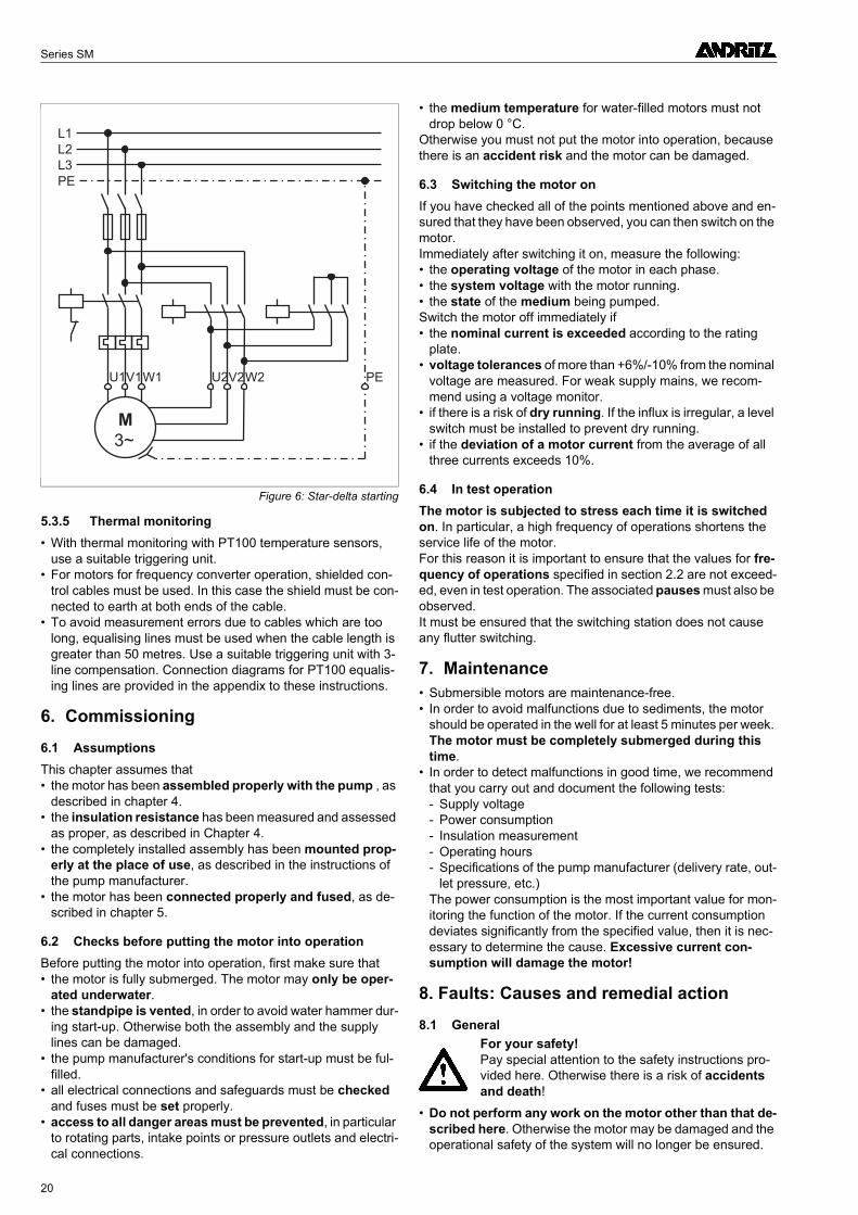
5.3.2 Earthing
• The motor must be earthed. When dimensioning the earth connection (4), pay particular attention to the motor power.
• For technical rules in this regard, please see EN 60034-1 and IEC 364-5-54.
5.3.3 Overvoltage protection
• Provide appropriate overvoltage protection (lightning pro-tection) in the voltage supply (5).
5.3.4 Connecting the 3-phase motor• The motors are suitable for use in the anti-clockwise direc-
tion (viewing the motor shaft from above). A clockwise direc-tion of rotation is only permissible if this is expressly permitted in the contract documentation.
• The motor rotates anti-clockwise or clockwise, depending on how it is connected.
• Connect the motor in such a way that the direction of rotation of the motor is the same as the direction of rotation of the pump.
• The motor rotates:- anti-clockwise (standard), if clockwise rotation is
present with phase sequence L1-L2-L3 (you can check this using a rotating-field-tester), and you connect the motor as designated below (L1-U,L2-V,L3-W).
- clockwise, if anti-clockwise rotation is present with phase sequence L1-L2-L3 (you can check this using a rotat-ing-field-tester), and you connect the motor as designated below (L1-U,L2-V,L3-W).
• The direction of rotation can be changed by exchanging the two wires.
• A motor protecting switch (overload relay) is absolutely es-sential! Only use- electromagnetic instantaneous tripping relays here.- Thermal tripping relays with a temperature compensation
of from 20 °C to 40 °C of the tripping class 10A or 10 accord-ing to EN 60947-4-1, with which the tripping time at 500% IN takes place within 10 seconds (starting with the bimetal in the cold state), and which are phase failure sensitive.
• Adjust the motor protecting device to the value of the meas-ured operating voltage, but at most to nominal motor cur-rent IN (acc. to the motor rating plate). We recommend a setting which is a max. of 90% of the nominal motor current.
• Undervoltage protection must be provided.
Figure 2: Fusing and motor protection
Figure 3: Earthing
Figure 4: Overvoltage protection
M
3~
I>
L1
L2
L3
PE
2
3
4
1
I> I>
U V W PE
U = blackV = brownW = blue
M
3~
PE4
L1
L2
L3
5
Figure 5: Direct starting
M
3~
L1
L2
L3
PE
U V W PE
19
Series SM
5.3.5 Thermal monitoring• With thermal monitoring with PT100 temperature sensors,
use a suitable triggering unit.• For motors for frequency converter operation, shielded con-
trol cables must be used. In this case the shield must be con-nected to earth at both ends of the cable.
• To avoid measurement errors due to cables which are too long, equalising lines must be used when the cable length is greater than 50 metres. Use a suitable triggering unit with 3-line compensation. Connection diagrams for PT100 equalis-ing lines are provided in the appendix to these instructions.
6. Commissioning
6.1 AssumptionsThis chapter assumes that• the motor has been assembled properly with the pump , as
described in chapter 4.• the insulation resistance has been measured and assessed
as proper, as described in Chapter 4.• the completely installed assembly has been mounted prop-
erly at the place of use, as described in the instructions of the pump manufacturer.
• the motor has been connected properly and fused, as de-scribed in chapter 5.
6.2 Checks before putting the motor into operationBefore putting the motor into operation, first make sure that• the motor is fully submerged. The motor may only be oper-
ated underwater.• the standpipe is vented, in order to avoid water hammer dur-
ing start-up. Otherwise both the assembly and the supply lines can be damaged.
• the pump manufacturer's conditions for start-up must be ful-filled.
• all electrical connections and safeguards must be checked and fuses must be set properly.
• access to all danger areas must be prevented, in particular to rotating parts, intake points or pressure outlets and electri-cal connections.
• the medium temperature for water-filled motors must not drop below 0 °C.
Otherwise you must not put the motor into operation, because there is an accident risk and the motor can be damaged.
6.3 Switching the motor onIf you have checked all of the points mentioned above and en-sured that they have been observed, you can then switch on the motor.Immediately after switching it on, measure the following:• the operating voltage of the motor in each phase.• the system voltage with the motor running.• the state of the medium being pumped.Switch the motor off immediately if• the nominal current is exceeded according to the rating
plate.• voltage tolerances of more than +6%/-10% from the nominal
voltage are measured. For weak supply mains, we recom-mend using a voltage monitor.
• if there is a risk of dry running. If the influx is irregular, a level switch must be installed to prevent dry running.
• if the deviation of a motor current from the average of all three currents exceeds 10%.
6.4 In test operationThe motor is subjected to stress each time it is switched on. In particular, a high frequency of operations shortens the service life of the motor.For this reason it is important to ensure that the values for fre-quency of operations specified in section 2.2 are not exceed-ed, even in test operation. The associated pauses must also be observed.It must be ensured that the switching station does not cause any flutter switching.
7. Maintenance• Submersible motors are maintenance-free.• In order to avoid malfunctions due to sediments, the motor
should be operated in the well for at least 5 minutes per week. The motor must be completely submerged during this time.
• In order to detect malfunctions in good time, we recommend that you carry out and document the following tests:- Supply voltage- Power consumption- Insulation measurement- Operating hours- Specifications of the pump manufacturer (delivery rate, out-
let pressure, etc.)The power consumption is the most important value for mon-itoring the function of the motor. If the current consumption deviates significantly from the specified value, then it is nec-essary to determine the cause. Excessive current con-sumption will damage the motor!
8. Faults: Causes and remedial action
8.1 General
• Do not perform any work on the motor other than that de-scribed here. Otherwise the motor may be damaged and the operational safety of the system will no longer be ensured.
Figure 6: Star-delta starting
M
3~
L1
L2
L3
PE
U1V1W1 PEU2V2W2
For your safety!Pay special attention to the safety instructions pro-vided here. Otherwise there is a risk of accidents and death!
20
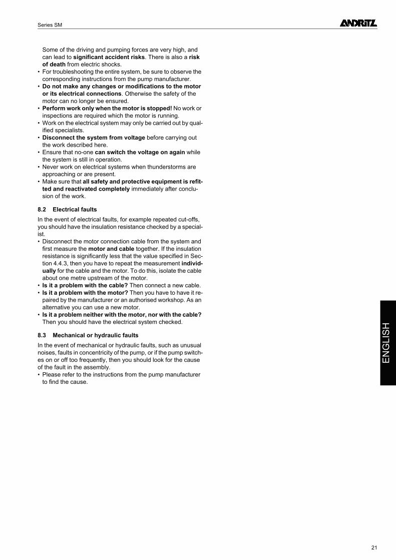
Series SM
EN
GL
ISH
Some of the driving and pumping forces are very high, and can lead to significant accident risks. There is also a risk of death from electric shocks.
• For troubleshooting the entire system, be sure to observe the corresponding instructions from the pump manufacturer.
• Do not make any changes or modifications to the motor or its electrical connections. Otherwise the safety of the motor can no longer be ensured.
• Perform work only when the motor is stopped! No work or inspections are required which the motor is running.
• Work on the electrical system may only be carried out by qual-ified specialists.
• Disconnect the system from voltage before carrying out the work described here.
• Ensure that no-one can switch the voltage on again while the system is still in operation.
• Never work on electrical systems when thunderstorms are approaching or are present.
• Make sure that all safety and protective equipment is refit-ted and reactivated completely immediately after conclu-sion of the work.
8.2 Electrical faultsIn the event of electrical faults, for example repeated cut-offs, you should have the insulation resistance checked by a special-ist.• Disconnect the motor connection cable from the system and
first measure the motor and cable together. If the insulation resistance is significantly less that the value specified in Sec-tion 4.4.3, then you have to repeat the measurement individ-ually for the cable and the motor. To do this, isolate the cable about one metre upstream of the motor.
• Is it a problem with the cable? Then connect a new cable.• Is it a problem with the motor? Then you have to have it re-
paired by the manufacturer or an authorised workshop. As an alternative you can use a new motor.
• Is it a problem neither with the motor, nor with the cable? Then you should have the electrical system checked.
8.3 Mechanical or hydraulic faultsIn the event of mechanical or hydraulic faults, such as unusual noises, faults in concentricity of the pump, or if the pump switch-es on or off too frequently, then you should look for the cause of the fault in the assembly.• Please refer to the instructions from the pump manufacturer
to find the cause.
21
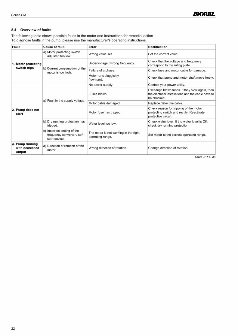
Series SM
8.4 Overview of faultsThe following table shows possible faults in the motor and instructions for remedial action. To diagnose faults in the pump, please use the manufacturer's operating instructions.
Fault Cause of fault Error Rectification
1. Motor protecting switch trips
a) Motor protecting switch adjusted too low.
Wrong value set. Set the correct value.
b) Current consumption of the motor is too high.
Undervoltage / wrong frequency.Check that the voltage and frequency correspond to the rating plate.
Failure of a phase. Check fuse and motor cable for damage.
Motor runs sluggishly (low rpm).
Check that pump and motor shaft move freely.
2. Pump does not start
a) Fault in the supply voltage.
No power supply. Contact your power utility.
Fuses blown.Exchange blown fuses. If they blow again, then the electrical installations and the cable have to be checked.
Motor cable damaged. Replace defective cable.
Motor fuse has tripped.Check reason for tripping of the motor protecting switch and rectify. Reactivate protective circuit.
b) Dry running protection has tripped.
Water level too low.Check water level. If the water level is OK, check dry running protection.
c) Incorrect setting of the frequency converter / soft-start device.
The motor is not working in the right operating range.
Set motor to the correct operating range.
3. Pump running with decreased output
a) Direction of rotation of the motor.
Wrong direction of rotation. Change direction of rotation.
Table 3: Faults
22
Série SM
FR
AN
ÇA
IS
Table des matières Page
1. Généralités.............................................................................................................................241.1 Introduction ........................................................................................................................................................................ 241.2 Désignation ........................................................................................................................................................................ 241.3 Plaque du constructeur ...................................................................................................................................................... 241.4 Consignes de sécurité........................................................................................................................................................ 24
2. À observer impérativement ..................................................................................................242.1 Application.......................................................................................................................................................................... 242.2 Exigences en matière de mise en œuvre........................................................................................................................... 252.3 Exigences des directives CE.............................................................................................................................................. 26
3. Transport et stockage...........................................................................................................263.1 Transport............................................................................................................................................................................ 263.2 Stockage ............................................................................................................................................................................ 263.3 Déballage........................................................................................................................................................................... 273.4 Première vérification .......................................................................................................................................................... 27
4. Monter le moteur ...................................................................................................................274.1 Outillage nécessaire........................................................................................................................................................... 274.2 Remplissage du moteur ..................................................................................................................................................... 274.3 Assemblage du moteur et de la pompe (groupe)............................................................................................................... 274.4 Brancher le câble du moteur .............................................................................................................................................. 28
5. Raccordement électrique......................................................................................................285.1 Conditions préalables......................................................................................................................................................... 285.2 Alimentation en énergie ..................................................................................................................................................... 295.3 Raccorder le moteur........................................................................................................................................................... 29
6. Mise en service......................................................................................................................306.1 Conditions préalables......................................................................................................................................................... 306.2 Contrôle avant la mise en service ...................................................................................................................................... 306.3 Mettre le moteur en marche............................................................................................................................................... 316.4 En mode d'essai................................................................................................................................................................. 31
7. Entretien.................................................................................................................................318.1 Généralités......................................................................................................................................................................... 318.2 Pannes électriques............................................................................................................................................................. 31
8. Défauts : Causes et dépannage ...........................................................................................318.1 Généralités......................................................................................................................................................................... 318.2 Pannes électriques............................................................................................................................................................. 318.3 Pannes mécaniques ou électriques ................................................................................................................................... 318.4 Aperçu des différentes pannes .......................................................................................................................................... 32
9. Annexe....................................................................................................................................339.1 Tableaux des valeurs de référence des températures de liquide de refroidissement........................................................ 339.2 Schéma des connexions PT100 avec ligne de compensation........................................................................................... 40
23
Série SM
1. Généralités
1.1 IntroductionNous vous félicitations d'avoir choisi nos moteurs immergés. Avec ce moteur, vous avez acheté un produit de grande quali-té, résultat de nombreuses années d'expériences dans le do-maine de la construction et de la technique des moteurs.Les instructions de service suivantes vous aident pour la mise en service et l'exploitation du moteur. Si toutefois vous devriez avoir besoin d'une assistance supplémentaire, veuillez-vous adresser à notre usine.Afin de permettre un traitement rapide et sans problèmes, en cas de questions, veuillez toujours indiquer le numéro de fa-brication du moteur. Vous trouvez ce nombre d'au moins 5 chiffres sur la plaque signalétique du moteur ou sur la face ex-térieure du couvercle supérieur du carter (palier de moteur su-périeur).
1.2 Désignation
1.3 Plaque du constructeurAvant de monter le monteur, nous vous recommandons de re-porter les caractéristiques techniques sur la plaque du constructeur dans le champ suivant. Ainsi, même après le mon-tage, vous aurez toujours les informations les plus importantes rapidement à portée de main.
1.4 Consignes de sécurité
• N'exploitez les moteurs qu'en observant de la manière la plus stricte les présentes instructions de service. Conservez les présentes instructions de service afin de pouvoir les consulter plus tard en cas de questions.
• Observez aussi, en plus des présentes instructions de service, les instructions de service spécifiques « Consi-gnes de sécurité », toutes les recommandations de la do-cumentation contractuelle ainsi que toutes les fiches techniques et instructions de service d'autres compo-sants éventuellement fournies (instructions de service de la pompe, etc.).
• Les moteurs ou les groupes entrés en contact avec des substances dangereuses pour la santé doivent être dé-contaminées avant de commencer les travaux. En cas de retour au fabricant ou d'envoi dans un atelier de réparation agréé, ces derniers doivent être décontami-nés avant l'envoi ou identifiés de manière clairement vi-sible.
• Immédiatement après la fin des travaux, tous les disposi-tifs de sécurité et de protection doivent être remis en œu-vre et en service.
• La sécurité de fonctionnement du moteur fourni par nos soins est uniquement garantie si le moteur est exploité conformément aux prescriptions et aux valeurs seuils de la documentation contractuelle (instructions de service, etc.) Les valeurs seuil prédéfinies ne doivent en aucun cas être dépassées.
2. À observer impérativement
2.1 ApplicationLes moteurs immergés rebobinables remplis à l'eau sont exclu-sivement conçus pour l'exploitation sous l'eau. Ils sont essen-tiellement utilisés pour l'entraînement de pompes.
Les moteurs sont livrés de série à l'état non rempli. Afin de garantir une lubrification et un refroidissement suffisants du moteur, il faut impérativement s'assurer que le moteur a été rempli et immergé conformément aux indications du fabricant avant de le mettre en service !
2.1.1 Domaines d'application typiquesLes domaines d'application typiques pour les pompes entraî-nées par des moteurs immergés sont les suivants :• l'adduction d'eau potable dans les villes et les communes.• les puits dans les usines de distribution d'eau.• l'exhaure dans les travaux publics et l'exploitation minière.• les installations d'augmentation de pression dans l'indus-
trie (avec pompe dans la chemise pressurisée).
2.1.2 Fluides admissiblesLes moteurs immergés doivent exclusivement être utilisés dans des fluides purs, très liquides, comme par exemple l'eau potable et l'eau industrielle.
Exemple
Illustration : Plaque du constructeur
SM 8 T / 75 / 2
Série
Diamètre de puits min. [pouces]
Modèle du moteur (en option)T = enroulement résistant à la chaleurF = modèle 60 HzR = exploitation minièreS = modèle spécial
Puissance du moteur P2 [kW]
Nombre de pôles
Typ
Bj.
Nr. Rep.
U V
I A
P1 kW P2 kW
n min-1
cos
Hz
Iso~ IP
�
• Les risques dus au courant électrique doivent être impérativement exclus (conformément aux directives du VDE et des distributeurs d'électricité).
• Les travaux sur le système électrique doivent uniquement être effectués par des spécialistes compétents.
• Avant les travaux d'entretien et de réparation, le moteur doit être complètement débranché de la tension d'alimentation électrique.
24
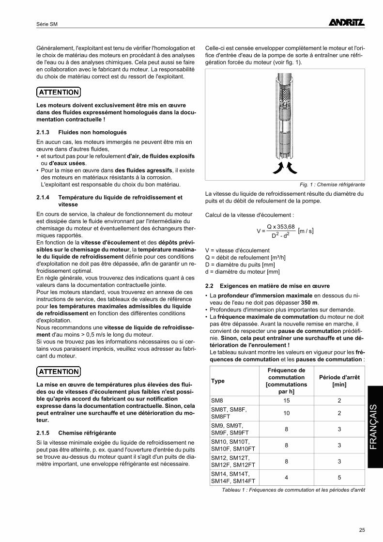
Série SM
FR
AN
ÇA
IS
Généralement, l'exploitant est tenu de vérifier l'homologation et le choix de matériau des moteurs en procédant à des analyses de l'eau ou à des analyses chimiques. Cela peut aussi se faire en collaboration avec le fabricant du moteur. La responsabilité du choix de matériau correct est du ressort de l'exploitant.
Les moteurs doivent exclusivement être mis en œuvre dans des fluides expressément homologués dans la docu-mentation contractuelle !
2.1.3 Fluides non homologuésEn aucun cas, les moteurs immergés ne peuvent être mis en œuvre dans d'autres fluides,• et surtout pas pour le refoulement d'air, de fluides explosifs
ou d'eaux usées.• Pour la mise en œuvre dans des fluides agressifs, il existe
des moteurs en matériaux résistants à la corrosion. L'exploitant est responsable du choix du bon matériau.
2.1.4 Température du liquide de refroidissement et vitesse
En cours de service, la chaleur de fonctionnement du moteur est dissipée dans le fluide environnant par l'intermédiaire du chemisage du moteur et éventuellement des échangeurs ther-miques rapportés.En fonction de la vitesse d'écoulement et des dépôts prévi-sibles sur le chemisage du moteur, la température maxima-le du liquide de refroidissement définie pour ces conditions d'exploitation ne doit pas être dépassée, afin de garantir un re-froidissement optimal.En règle générale, vous trouverez des indications quant à ces valeurs dans la documentation contractuelle jointe.Pour les moteurs standard, vous trouverez en annexe de ces instructions de service, des tableaux de valeurs de référence pour les températures maximales admissibles du liquide de refroidissement en fonction des différentes conditions d'exploitation.Nous recommandons une vitesse de liquide de refroidisse-ment d'au moins > 0,5 m/s le long du moteur.Si vous ne trouvez pas les informations nécessaires ou si cer-tains vous paraissent imprécis, veuillez vous adresser au fabri-cant du moteur.
La mise en œuvre de températures plus élevées des flui-des ou de vitesses d'écoulement plus faibles n'est possi-ble qu'après accord du fabricant ou sur notification expresse dans la documentation contractuelle. Sinon, cela peut entraîner une surchauffe et une détérioration du mo-teur.
2.1.5 Chemise réfrigéranteSi la vitesse minimale exigée du liquide de refroidissement ne peut pas être atteinte, p. ex. quand l'ouverture d'entrée du puits se trouve au-dessus du moteur quant il s'agit d'un puits de dia-mètre important, une enveloppe réfrigérante est nécessaire.
Celle-ci est censée envelopper complètement le moteur et l'ori-fice d'entrée d'eau de la pompe de sorte à entraîner une réfri-gération forcée du moteur (voir fig. 1).
La vitesse du liquide de refroidissement résulte du diamètre du puits et du débit de refoulement de la pompe.
Calcul de la vitesse d'écoulement :
V = vitesse d'écoulement Q = débit de refoulement [m³/h] D = diamètre du puits [mm] d = diamètre du moteur [mm]
2.2 Exigences en matière de mise en œuvre• La profondeur d'immersion maximale en dessous du ni-
veau de l'eau ne doit pas dépasser 350 m.• Profondeurs d'immersion plus importantes sur demande.• La fréquence maximale de commutation du moteur ne doit
pas être dépassée. Avant la nouvelle remise en marche, il convient de respecter une pause de commutation prédéfi-nie. Sinon, cela peut entraîner une surchauffe et une dé-térioration de l'enroulement ! Le tableau suivant montre les valeurs en vigueur pour les fré-quences de commutation et les pauses de commutation :
Fig. 1 : Chemise réfrigérante
Type
Fréquence de commutation
[commutationspar h]
Période d'arrêt[min]
SM8 15 2
SM8T, SM8F, SM8FT
10 2
SM9, SM9T, SM9F, SM9FT
8 3
SM10, SM10T, SM10F, SM10FT
8 3
SM12, SM12T, SM12F, SM12FT
8 3
SM14, SM14T, SM14F, SM14FT
4 5
Tableau 1 : Fréquences de commutation et les périodes d'arrêt
[ ]VQ x
D dm s=
-
353 682 2
,/
25
Série SM
• La dissipation de la chaleur de fonctionnement du mo-teur dans le fluide de refoulement s'effectue par la surface du moteur. La mise en œuvre dans des fluides présentant un danger de formation de dépôts, est uniquement autorisée si la documentation contractuelle l'autorise expressément.
• Aucune couche de peinture supplémentaire ne doit être appliquée sur le moteur car elles nuisent à la dissipation de chaleur du moteur.
• En règle générale, selon les paramètres de la commande, le moteur est approprié pour la commutation directe (DOL) ou étoile-triangle. Le démarrage par démarreur progressif ou le fonctionnement via convertisseur de fréquence ne sont autorisés que si expressément autorisé dans la documenta-tion contractuelle. L'utilisation d'un démarreur progressif ou d'un convertisseur de fréquence nécessite une conception spéciale du moteur ou pose des exigences aux appareils (dé-marreur progressif, convertisseur de fréquence, etc.) et à leurs réglages.
• Les moteurs se prêtent au montage à la verticale (bout d'ar-bre d'entraînement orienté vers le haut). Un montage hori-zontal ne peut être effectué que s'il est expressément autorisé dans la documentation contractuelle.
• Prévoyez impérativement un clapet antiretour dans la conduite ascendante si un tel dispositif n'est pas déjà intégré à la pompe. Nous recommandons l'utilisation d'un clapet an-tiretour commandé par ressort.
• Pour les puits avec afflux d'eau variable, il est recommandé d'installer un contrôleur de niveau pour empêcher toute mar-che à sec du moteur et de la pompe.
La marche à sec entraîne immédiatement des défauts au niveau du moteur et de la pompe.
2.2.1 Exigences spéciales - Démarrage avec démarreur progressif
• Tension de démarrage : UA ≥ 70 % de la tension assignée• Temps de montée en régime/Rampe : Préréglage sur tH ≤ 5 s
(la durée effective jusqu'à ce que la vitesse assignée soit at-teinte est alors de 2 à 3 s).
• Temps de ralentissement/Rampe: Préréglage tA ≤ 5 s. Si pos-sible, il faudrait entièrement renoncer à la rampe de ralentis-sement.
• Après la montée en régime, le démarreur progressif doit être shunté par un contacteur-disjoncteur afin d'éviter toute perte de puissance au niveau du démarreur progressif et du mo-teur. Et tout particulièrement, à ce propos, veuillez demander conseil au fournisseur du démarreur progressif.
2.2.2 Exigences spéciales - Fonctionnement avec un convertisseur de fréquence
• En raison des pertes électriques plus importantes dans le mo-teur, lors de la conception du moteur, il faut prévoir une réser-ve de puissance d'au moins 10 %.
• Fréquence de fonctionnement minimale : fmin = 30 Hz Veiller à une vitesse de liquide de refroidissement suffi-sante le long du moteur.
• Fréquence de fonctionnement maximale : fmax = fréquence nominale du moteur Selon le modèle de moteur, la fréquence nominale du moteur est de 50 ou de 60 Hz ! Veuillez consulter la plaque signalé-tique ou la documentation contractuelle. La fréquence nomi-nale et la puissance nominale du moteur ne doivent pas être dépassées.
• Temps de montée en régime (f = 0 à fmin): tH = 3 s.
• Temps de ralentissement (f = fmin à 0 ): tA = 3 s.• Le courant assigné du moteur ne doit pas être dépassé.• Accroissement de tension maximale admissible ≤ 500 V/µs.
Pic de tension maximal admissible par rapport à la terre avec isolation PVC ≤ 800 V et avec isolation PE2/PA ≤ 1000 V. Recommandation : En règle générale, ces valeurs limite sont atteintes à l'aide d'un filtre sinusoïdal ou d'un filtre du/dt.
• La procédure de commande et de réglage du convertisseur de fréquence doit correspondre à une commande caractéris-tique U/f linéaire. Avec d'autres principes de commande et de réglage, le fabricant du convertisseur de fréquence doit s'as-surer que les conditions particulières aux moteurs immergés soient prises en compte.
• Les lignes d'énergie et de commande entre le moteur et la tê-te de forage doivent être posées séparément et branchés dans une boîte de jonction. Les lignes de commande utilisées doivent être blindées.
• Les lignes posées sur le site d'implantation entre la boîte de jonction et le dispositif de commutation doivent être des li-gnes de raccordement blindées.
2.3 Exigences des directives CEEn ce qui concerne les moteurs immergés, il s'agit d'un compo-sant conforme à la directive CE « Machines ». En conséquen-ce, vous ne devez mettre le moteur en service que lorsque• vous avez construit une machine complète , p. ex. en assu-
rant la jonction avec la pompe à entraîner,• vous avez rempli les exigences de protection imposées aux
termes des directives CE applicables,• le respect des exigences de protection est attesté par la dé-
claration de conformité CE• et que l'apposition du sigle CE l'identifie de manière visible
pour l'extérieur !
3. Transport et stockage
3.1 Transport
Ne pas cogner le moteur contre des obstacles solides lors de la manutention et du transport !
3.2 StockageLes moteurs immergés sons soumis à des exigences spéciales en matière de stockage, car, en raison de conditions techni-ques marginales, certains composants du moteur ne peuvent pas être fabriqués en matériaux résistants à la corrosion. Tout non-respect de ces exigences entraîne des dommages du mo-teur. Le parfait fonctionnement du moteur dépend de son bon positionnement.
• La livraison des moteurs s'effectue de série sans rem-plissage du moteur. Si c'est le cas, immédiatement après la réception, il faut remplir le moteur d'eau potable propre (pas d'eau distillée) !
Danger de blessure• Tenir compte du poids et du centre de gravité.• N'utiliser qu'un moyen de transport approprié et un
engin de levage de charge portante suffisante.• Ne pas faire basculer le moteur lors du transport.• Ne pas stationner en dessous de charges suspen-
dues.• Eviter toute contrainte de traction au niveau des
câbles de raccordement et de commande.• En cas d'utilisation de chaînes et de câbles en
acier, attention aux risques de dérapage.
26
Série SM
FR
AN
ÇA
IS
• Local de stockage : exempt de poussières, sec, protégé contre la chaleur et le gel.
• Ne pas stocker le moteur dans une zone soumise à un enso-leillement direct ou à d'autres sources de chaleur. En aucun cas le moteur ne doit être chauffé à plus de 60 °C. Sinon, le liquide du moteur pourrait s'en échapper par expansion. Ce qui pourrait causer des dommages ultérieurs au moteur.
• En cas de stockage du moteur à des températures inférieures à zéro, un produit antigel est nécessaire. À ce propos, veuillez contacter le fabricant. L'utilisation de produits antigel incorrects, non autorisés peut gravement endommager le moteur.
• Stocker le moteur à la verticale (bout d'arbre d'entraîne-ment vers le haut) ! Lors du stockage vertical, assurez-vous que le moteur ne puisse pas basculer.
• Tourner l'arbre du moteur tous les mois. Rétablir la position précédente de l'arbre.
3.3 DéballageVérifier l'intégrité et l'absence de dommage de la livraison. Fai-re consigner par l'entreprise de transport les défauts constatés sur le bon de livraison d'origine et nous signaler lesdits défauts sans tarder.
3.4 Première vérificationAprès le déballage, vérifier si des dommages sont visibles de l'extérieur, par exemple• sur le fond du carter• sur le carter (stator)• sur le couvercle de carter supérieur et inférieur (palier du
moteur)• sur les câbles de raccordement ou de commande
4. Monter le moteur
4.1 Outillage nécessairePour les vérifications nécessaires et un montage parfait, voici les outils et instruments dont vous avez besoin :• appareil de mesure d'isolement avec 500 Volts de tension
d'essai ou 5000 Volts de tension d'essai pour les moteurs haute tension de plus de 3000 Volts de tension de service. Afficheur jusqu'à au moins 200 Mohm.
• outillage approprié pour le remplissage et l'assemblage du moteur (récipient d'eau, entonnoir, clé plate, clé dynamomé-trique, etc.).
4.2 Remplissage du moteur
• Avant l'installation, le moteur doit être rempli d'eau pota-ble propre (pas d'eau distillée).
• Si le moteur a été livré avec plein d'eau ou qu'il a déjà été rempli pour les besoins du stockage, il faut contrôler le plein d'eau avant l'installation. Si la vérification met en évidence qu'il manque du liquide moteur, vous pouvez ajouter de l'eau potable propre (pas d'eau distillée) et fai-re l'appoint.
• Veuillez utiliser de l'eau de remplissage présentant un pH en-tre 7 et 7,5, d'une dureté comprise entre 7 et 8 et contenant 10 à 20 mg/l de nitrate. Il ne doit pas y avoir de sable ni de matières en suspension. Appareils de mesure adaptés dispo-nibles sur demande.
• Avant d'être mise en œuvre dans de l'eau potable, les mo-teurs conservés pour le stockage ou remplis d'antigel, doivent être vidés, rincés, nettoyés et remplis à nouveau d'eau pota-ble propre.
4.2.1 Remplissage du liquide moteur
• Amener le moteur en position verticale.• Le moteur doit être systématiquement rempli en position ver-
ticale !• Retirer la vis de fermeture de l'orifice de remplissage et de
purge.• Insérer l'entonnoir (entonnoir coudé) dans l'orifice de remplis-
sage.• Remplir le moteur d'eau non pressurisée par l'entonnoir jus-
qu'à ce que l'eau émerge de l'orifice de remplissage.• Au bout de 2 heures, contrôler à nouveau le niveau de rem-
plissage. Poursuivre la procédure de remplissage jusqu'à ce que l'eau stagne sans bulles dans l'orifice de remplissage et de purge.
• Revisser la vis de fermeture de manière étanche sans oublier le joint.
4.3 Assemblage du moteur et de la pompe (groupe)
4.3.1 Vérifications préparatoires• Retirez éventuellement la protection d'arbre.• Avant l'assemblage, tournez l'arbre à la main ou à l'aide d'un
outil. Utiliser impérativement un outil approprié pour éviter de causer des dommages mécaniques sur l'arbre. Après avoir surmonté le frottement statique, l'arbre doit tourner librement. Dans le cas contraire, il faut déterminer la cause.
• Veillez à ce que les surfaces des éléments à relier soient exemptes de saleté et de poussière.
4.3.2 Assemblage
4.3.2.1 Moteurs avec accouplement NEMA (SM8, SM9)• Enduisez l'intérieur de l'accouplement d'une graisse hydroré-
sistante et sans acides (p. ex. Mobil FM 102, Texaco Cygnus 2661, Gleitmo 746). La graisse minimise le frottement et offre une protection supplémentaire contre la pénétration du sable.
• Lors de l'assemblage du moteur et de la pompe, veillez à ce que l'endentement soit recouvert par un joint torique. Ce joint torique empêche toute pénétration de sable et de saleté dans l'endentement de l'arbre.
Danger de blessure• Sortir le moteur de son emballage avec précaution
afin d'éviter tout dommage.• Tenir compte du poids et du centre de gravité.• N'utiliser qu'un engin de levage approprié et de
charge portante suffisante.• Ne pas stationner en dessous de charges suspen-
dues.• Protéger les câbles du moteur de tout influence
mécanique.
Si des dommages sont constatés, ne pas monter le moteur ni le mettre en service. Avec un moteur en-dommagé, il y a des risques de blessures et pou-vant être mortelles.
Danger de blessure !Veillez à ce que le moteur ne puisse pas se renver-ser pendant la procédure.
Ne jamais utiliser le moteur avec des pompes ou des éléments endommagés. Sinon, les impor-tantes forces d'entraînement pourraient provo-quer des accidents. Danger de blessures et de mort !
27
Série SM
• Alignez l'arbre de la pompe par rapport à l'arbre du moteur et assemblez la pompe et le moteur.
• Les arbres de la pompe et du moteur ne doivent pas consti-tuer de liaison rigide (accouplement) dans le sens axial.
• L'accouplement doit être fixé sur l'arbre de la, pompe et doit coulisser sur l'arbre du moteur.
• N'utiliser que des vis de fixation de classe de qualité et de dimensions correspondantes et prescrites et homologuées par le fabricant de la pompe.
• Observez les couples de serrage prescrits par le fabricant de la pompe.
• Vissez le moteur sur le groupe et serrer les vis de fixation en croix conformément aux prescriptions.
4.3.2.2 Moteurs avec accouplement de l'arbre (SM10, SM12, SM14)
Le montage du moteur et de la pompe nécessite des connais-sances spéciales relatives au réglage de la pompe et doit être effectué conformément aux exigences de la pompe.Lors du montage, il faut veiller au dimensionnement suffisant des éléments de jonction et aux mouvements libres du rotor.
4.3.3 Vérifications finalesSi l'emplacement d'accouplement devait être librement acces-sible en cours de service, vous devez impérativement le pro-téger contre tout contact !
4.4 Brancher le câble du moteur
• Le câble ne doit en aucun cas se trouver en contact avec des arêtes vives.
• Posez le câble le long de la pompe et protégez-le de toute dé-térioration à l'aide de la baguette de protection du câble. Pour ce faire, observez les indications du fabricant de la pompe.
4.4.1 Branchement du conducteur de mise à la terre
• Vérifiez si les moteurs ont été livrés avec un conducteur de mise à la terre. Cela dépend de la variante de branchement du moteur.
• Sur site, il faut veiller au branchement dans les règles d'un conducteur de mise à la terre. Si le moteur ne possède pas de conducteur de mise à la terre, vous trouverez sur le cou-vercle de carter supérieur une borne de mise à la terre cor-respondante sur laquelle il faut brancher dans les règles un conducteur de mise à la terre distinct.
4.4.2 Rallonge du câble du moteurLe câble du moteur fourni peut être rallongé sur site. Pour ce faire, utilisez uniquement des rallonges
- dont le matériau est compatible avec l'utilisation.- homologués pour les températures existantes dans votre
fluide.- présentant une section suffisante pour les conditions (puis-
sance, longueur du câble, etc.)..• Lors du choix du câble, tenez autant compte d'une résistan-
ce diélectrique correspondante que de la compatibilité avec le fluide (en particulier avec l'eau potable). Lors de votre choix, vérifiez la chute de tension sur le câble afin d'obser-
ver les consignes des tolérances de la tension d'alimentation du moteur ! Toute non observation peut entraîner une dété-rioration du moteur due à la surchauffe.
• C'est le monteur-électricien qui est responsable du choix et du dimensionnement correct du câble !
• Protégez le point de jonction des câbles contre toute pénétra-tion possible d'eau. Pour ce faire, il existe sur le marché des gaines thermorétractables, des masses de scellement ou des garnitures de câble prêtes à l'emploi.
• Observez les instructions du fournisseur concerné sur l'utili-sation du matériau isolant.
• Fixer soigneusement le câble sur chaque conduite ascendan-te à l'aide de serre-câbles ou de colliers pour câbles. Selon la taille et le poids du câble, la fixation doit s'effectuer au moins tous les 3 m, voire moins. Le câble ne doit en aucun cas être soumis à la moindre contrainte de traction.
• Dans ce contexte, veuillez également observer les indications du fabricant de la pompe.
4.4.3 Mesurer la résistance d'isolementEffectuez la mesure avant et pendant la descente sur le site d'exploitation du groupe monté.• Pendant la descente, reliez l'un des câbles de mesure au
conducteur de mise à la terre.• Puis, reliez l'autre câble de mesure l'un après l'autre avec
chacun des brins du câble moteur raccordé, mais pas avec le conducteur de mise à la terre.
• Veillez à ce que les points de contact soient propres.• Le moteur est en ordre de marche quand la résistance d'iso-
lement ne dépasse par la valeur indiquée dans le tableau sui-vant. Pour que la mesure soit correcte, le moteur doit être complet.
5. Raccordement électrique
5.1 Conditions préalablesCe chapitre suppose que• le moteur est assemblé avec la pompe dans les règles,
comme décrit au chapitre 4.• la résistance d'isolement a été mesurée et jugée parfaite,
comme décrit au chapitre 4.
• Lors du montage (et également lors de la traction du groupe), le câble doit être stocké soigneuse-ment enroulé ou déposé, afin d'éviter, dans le cas d'une chute éventuelle de la pompe dans le puits, toute blessure corporelle ou dommage matériel, occasionné par le câble, forcément entraîné par le poids.
• Il faut veiller à ce personne ne mette le pied dans la spirale de câble déroulée.
Etat du moteur Tension> 1000 Volts
Moteur neuf 500 MOhm
Moteur installé/ réparé 200 MOhm
Tableau 2 : Résistances d'isolement
28
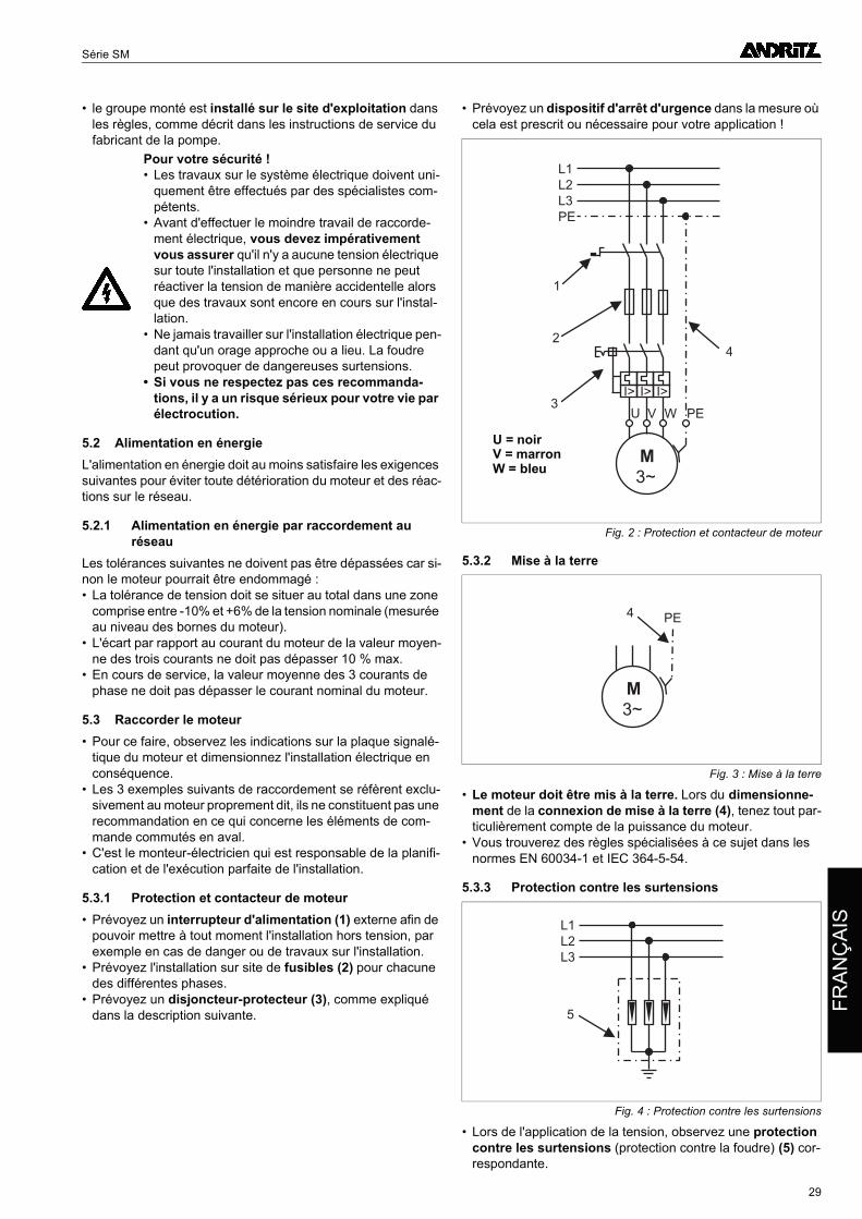
Série SM
FR
AN
ÇA
IS
• le groupe monté est installé sur le site d'exploitation dans les règles, comme décrit dans les instructions de service du fabricant de la pompe.
5.2 Alimentation en énergieL'alimentation en énergie doit au moins satisfaire les exigences suivantes pour éviter toute détérioration du moteur et des réac-tions sur le réseau.
5.2.1 Alimentation en énergie par raccordement au réseau
Les tolérances suivantes ne doivent pas être dépassées car si-non le moteur pourrait être endommagé :• La tolérance de tension doit se situer au total dans une zone
comprise entre -10% et +6% de la tension nominale (mesurée au niveau des bornes du moteur).
• L'écart par rapport au courant du moteur de la valeur moyen-ne des trois courants ne doit pas dépasser 10 % max.
• En cours de service, la valeur moyenne des 3 courants de phase ne doit pas dépasser le courant nominal du moteur.
5.3 Raccorder le moteur• Pour ce faire, observez les indications sur la plaque signalé-
tique du moteur et dimensionnez l'installation électrique en conséquence.
• Les 3 exemples suivants de raccordement se réfèrent exclu-sivement au moteur proprement dit, ils ne constituent pas une recommandation en ce qui concerne les éléments de com-mande commutés en aval.
• C'est le monteur-électricien qui est responsable de la planifi-cation et de l'exécution parfaite de l'installation.
5.3.1 Protection et contacteur de moteur• Prévoyez un interrupteur d'alimentation (1) externe afin de
pouvoir mettre à tout moment l'installation hors tension, par exemple en cas de danger ou de travaux sur l'installation.
• Prévoyez l'installation sur site de fusibles (2) pour chacune des différentes phases.
• Prévoyez un disjoncteur-protecteur (3), comme expliqué dans la description suivante.
• Prévoyez un dispositif d'arrêt d'urgence dans la mesure où cela est prescrit ou nécessaire pour votre application !
5.3.2 Mise à la terre
• Le moteur doit être mis à la terre. Lors du dimensionne-ment de la connexion de mise à la terre (4), tenez tout par-ticulièrement compte de la puissance du moteur.
• Vous trouverez des règles spécialisées à ce sujet dans les normes EN 60034-1 et IEC 364-5-54.
5.3.3 Protection contre les surtensions
• Lors de l'application de la tension, observez une protection contre les surtensions (protection contre la foudre) (5) cor-respondante.
Pour votre sécurité !• Les travaux sur le système électrique doivent uni-
quement être effectués par des spécialistes com-pétents.
• Avant d'effectuer le moindre travail de raccorde-ment électrique, vous devez impérativement vous assurer qu'il n'y a aucune tension électrique sur toute l'installation et que personne ne peut réactiver la tension de manière accidentelle alors que des travaux sont encore en cours sur l'instal-lation.
• Ne jamais travailler sur l'installation électrique pen-dant qu'un orage approche ou a lieu. La foudre peut provoquer de dangereuses surtensions.
• Si vous ne respectez pas ces recommanda-tions, il y a un risque sérieux pour votre vie par électrocution.
Fig. 2 : Protection et contacteur de moteur
Fig. 3 : Mise à la terre
Fig. 4 : Protection contre les surtensions
M
3~
I>
L1
L2
L3
PE
2
3
4
1
I> I>
U V W PE
U = noirV = marronW = bleu
M
3~
PE4
L1
L2
L3
5
29
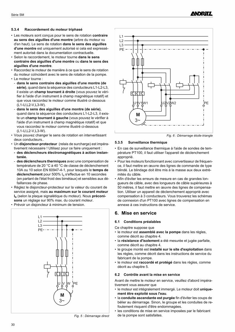
Série SM
5.3.4 Raccordement du moteur triphasé• Les moteurs sont conçus pour le sens de rotation contraire
au sens des aiguilles d'une montre (arbre du moteur vu d'en haut). Le sens de rotation dans le sens des aiguilles d'une montre est uniquement autorisé si cela est expressé-ment autorisé dans la documentation contractuelle.
• Selon le raccordement, le moteur tourne dans le sens contraire des aiguilles d'une montre ou dans le sens des aiguilles d'une montre.
• Raccordez le moteur de manière à ce que le sens de rotation du moteur coïncident avec le sens de rotation de la pompe.
• Le moteur tourne :- dans le sens contraire des aiguilles d'une montre (de
série), quand dans la séquence des conducteurs L1-L2-L3, il existe un champ tournant à droite (vous pouvez le véri-fier à l'aide d'un instrument à champ magnétique rotatif) et que vous raccordez le moteur comme illustré ci-dessous (L1-U,L2-V,L3-W).
- dans le sens des aiguilles d'une montre (de série), quand dans la séquence des conducteurs L1-L2-L3, il exis-te un champ tournant à gauche (vous pouvez le vérifier à l'aide d'un instrument à champ magnétique rotatif) et que vous raccordez le moteur comme illustré ci-dessous (L1-U,L2-V,L3-W).
• Vous pouvez changer le sens de rotation en intervertissant deux conducteurs..
• Un disjoncteur-protecteur (relais de surcharge) est impéra-tivement nécessaire ! Utilisez pour ce faire uniquement :- des déclencheurs électromagnétiques à action instan-
tanée.- des déclencheurs thermiques avec une compensation de
température de 20 °C à 40 °C de classe de déclenchement 10A ou 10 selon EN 60947-4-1, pour lesquels le temps de déclenchement pour 500% IN s'effectue en 10 secondes (en partant de l'état froid des bimétaux) et sensibles aux dé-faillances de phase.
• Réglez le disjoncteur-protecteur sur la valeur du courant de service assigné, mais au maximum sur le courant moteur IN (selon la plaque signalétique du moteur). Nous préconi-sons un réglage sur 90% max. du courant moteur.
• Prévoir un disjoncteur à minimum de tension.
5.3.5 Surveillance thermique• En cas de surveillance thermique à l'aide de sondes de tem-
pérature PT100, il faut utiliser l'appareil de déclenchement approprié.
• Pour les moteurs fonctionnant avec convertisseur de fréquen-ce, il faut mettre en œuvre des lignes de commande de type blindé. Le blindage doit être mis à la masse aux deux extré-mités du câble.
• Afin d'éviter les erreurs de mesure en cas de grandes lon-gueurs de câble, avec des longueurs de câble supérieures à 50 mètres, il faut mettre en œuvre des lignes de compensa-tion. Utiliser un appareil de déclenchement approprié avec compensation à 3 conducteurs. Vous trouverez les schémas de connexion d'un PT100 avec lignes de compensation en annexe à ces instructions de service.
6. Mise en service
6.1 Conditions préalablesCe chapitre suppose que• le moteur est assemblé avec la pompe dans les règles,
comme décrit au chapitre 4.• la résistance d'isolement a été mesurée et jugée parfaite,
comme décrit au chapitre 4.• le groupe monté est installé sur le site d'exploitation dans
les règles, comme décrit dans les instructions de service du fabricant de la pompe.
• le moteur est raccordé et protégé dans les règles, comme décrit au chapitre 5.
6.2 Contrôle avant la mise en serviceAvant de mettre le moteur en service, veuillez d'abord impéra-tivement vous assurer que• le moteur est intégralement immergé. Le moteur doit unique-
ment être exploité sous l'eau.• la conduite ascendante est purgée fin d'éviter les coups de
bélier au démarrage. Sinon, le groupe et les conduites de re-foulement risquent d'être endommagées.
• les conditions de mise en service imposées par le fabricant de la pompe sont satisfaites.Fig. 5 : Démarrage direct
M
3~
L1
L2
L3
PE
U V W PE
Fig. 6 : Démarrage étoile-triangle
M
3~
L1
L2
L3
PE
U1V1W1 PEU2V2W2
30
Série SM
FR
AN
ÇA
IS
• tous les raccordements et dispositifs de protection électriques sont vérifiés et que les protections par fusibles sont correc-tement réglées.
• plus aucune zone de danger n'est librement accessible, en particulier aucune pièce rotative, aucune zone d'aspiration ou sortie sous pression et aucun branchement électrique.
• la température du fluide ne chute pas dessous de 0 °C pour les moteurs remplis d'eau.
Sinon, vous ne devez pas mettre le moteur en service en raison du risque d'accident et de la possibilité de détérioration du moteur !
6.3 Mettre le moteur en marcheUne fois que vous avez vérifié tous les points précédemment ci-tés et que leur respect est garanti, vous pouvez mettre le mo-teur en marche.Immédiatement après le démarrage, mesurez :• le courant de service du moteur au niveau de chaque pha-
se.• la tension de réseau, moteur en marche.• l'état du fluide à refouler.Coupez immédiatement le moteur si• un dépassement du courant nominal, selon les indications
de la plaque signalétique, survient.• des tolérances de tension de plus de +6%/-10% par rap-
port à la tension nominale sont constatées. Avec les réseaux d'alimentation de faible puissance, nous recommandons d'installer un dispositif de surveillance de la tension !
• une marche à sec menace. En cas d'afflux irrégulier, le mon-tage d'un contrôleur de niveau s'avère nécessaire pour éviter toute marche à sec.
• l'écart d'un courant moteur par rapport à la valeur moyenne des trois courants est supérieure à 10%.
6.4 En mode d'essaiTout démarrage sollicite le moteur. Et plus particulièrement, une grande fréquence de commutation réduit la durée de vie du moteur !Assurez-vous donc de ne pas dépasser les valeurs indiquées au point 2.2 relatives à la fréquence de commutation, même en mode d'essai. Respecter également la période d'arrêt cor-respondante !Il faut s'assurer que l'installation de commutation ne peut pas engendrer de commutations fréquentes.
7. Entretien• Les moteurs immergés sont sans entretien.• Afin d'éviter les dysfonctionnements dus aux dépôts, il faut
mettre en service le moteur dans le puits au moins une fois par semaine pendant 5 minutes. Le moteur doit être totale-ment immergé.
• Pour détecter à temps les dysfonctionnements, nous vous re-commandons d'effectuer les essais suivants et d'en consi-gner les résultats :- Tension d'alimentation- Consommation de courant- Mesure de l'isolement- Heures de service- Consignes du fabricant de la pompe (quantité refoulée,
pression de refoulement, etc.)La consommation de courant est la valeur la plus importante pour surveiller le fonctionnement du moteur. En cas d'écarts importants de la consommation de courant par rapport à la valeur de consigne, il faut déterminer la cause. Une trop for-te consommation de courant est nuisible au moteur !
8. Défauts : Causes et dépannage
8.1 Généralités
• N'effectuez aucun autre travail sur le moteur que ceux décrits ci-après. Le moteur pourrait sinon être détruit et la sécurité de fonctionnement de l'installation ne serait plus ga-rantie. En raison des forces d'entraînement et de refoulement en partie très importantes, d'importants risques d'accident peuvent être générés. Il existe aussi danger de mort par dé-charge électrique.
• Pour rechercher et corriger les pannes sur la totalité de l'ins-tallation, veuillez impérativement observer les indications cor-respondantes dans les instructions de service du fabricant de la pompe !
• Ne procédez à aucune modification ou transformation du moteur ou de ses raccordements électriques. Dans le cas contraire, la sécurité du moteur ne serait plus garantie.
• Ne travaillez qu'à l'arrêt ! Aucun travail ni contrôle n'est né-cessaire en cours de service.
• Les travaux sur le système électrique doivent uniquement être effectués par des spécialistes compétents.
• Mettez l'installation hors tension, avant de procéder aux travaux décrits ici.
• Veuillez-vous assurer que personne ne peut réactiver invo-lontairement la tension, alors que des travaux sont encore en cours sur l'installation !
• Ne jamais travailler sur l'installation électrique pendant qu'un orage approche ou a lieu.
• Veuillez faire en sorte que, juste après la fin des travaux , tous les dispositifs de sécurité et de protection soient à nouveau intégralement remontés et à nouveau opéra-tionnels.
8.2 Pannes électriquesEn cas de pannes électriques comme par exemple, les décon-nexions répétées, il faut faire vérifier la résistance d'isolement par un spécialiste.• Débranchez le câble de raccordement du moteur de l'instal-
lation et commencez par mesurer ensemble le moteur et le câble. Si la résistance d'isolement est sensiblement inférieu-re à la valeur de consigne donnée au point 4.4.3, vous devez répéter la mesure séparément pour le câble et le moteur. Pour ce faire, coupez le câble environ un mètre avant le mo-teur.
• Est-ce le câble qui est en cause ? Alors, branchez un nou-veau câble.
• Est-ce le moteur qui est en cause ? Vous devez le faire ré-viser par le fabricant ou par un atelier de réparation agréé. Al-ternativement, il est possible de mettre en œuvre un moteur neuf.
• Ni le câble ni le moteur ne sont en cause ? Vous devez fai-re vérifier l'installation électrique.
8.3 Pannes mécaniques ou électriquesEn cas de pannes mécaniques ou hydrauliques comme par exemple, des bruits inhabituels, des défauts de rotation de la pompe ou une activation/désactivation trop fréquente de la pompe, il faut rechercher la cause de la panne au niveau du groupe.• Pour ce faire, consultez les instructions de service du fabri-
cant de la pompe pour déceler la cause.
Pour votre sécurité !Observez tout particulièrement les consignes de sé-curité ci-après. Sinon, il y a un risque d'accident et un danger de mort !
31
Série SM
8.4 Aperçu des différentes pannesLe tableau suivant regroupe les défauts possibles du moteur et des indications quant à leur élimination. Pour le diagnostic des pannes survenues sur la pompe, veuillez consulter les instructions de service du fabricant de la pompe.
Panne Cause de la panne Elimination du défaut
1. Disjoncteur- contacteur se déclenche
a) Disjoncteur-contacteur réglé trop bas.
Valeur incorrecte réglée. Réglage de la valeur correcte.
b) La consommation du moteur est trop élevée.
Sous-tension / Fréquence incorrecte.Vérifier la coïncidence de la tension et de la fréquence avec les valeurs de la plaque signalétique.
Défaillance d'une phase.Vérifier les fusibles et le câble du moteur quant aux dommages.
Le moteur tourne difficilement (faible vitesse de rotation).
Vérifier la rotation libre de l'arbre de la pompe et du moteur.
2. La pompe ne démarre pas
a) Défaut de la tension d'alimentation.
Pas d'alimentation en courant.Prendre contact avec la société distributrice d'électricité.
Fusibles claqués.Remplacer les fusibles claqués. Si ces derniers claquent encore une fois, il faut vérifier l'installation électrique et le câble.
Câble du moteur endommagé. Remplacer le câble défectueux.
Le coupe-circuit du moteur s'est déclenché.
Vérifier et éliminer la cause du déclenchement du disjoncteur-protecteur. Remettre le circuit protecteur en service.
b) La protection contre la marche à vide s'est déclenchée.
Niveau d'eau trop bas.Vérifier le niveau d'eau. Si le niveau d'eau est correct, vérifier la protection contre la marche à vide.
c) Réglage incorrect du convertisseur de fréquence / démarreur progressif.
Le moteur ne travaille pas dans la plage de service correcte.
Réglage de la plage de service correcte.
3. La pompe tourne à puissance réduite
a) Sens de rotation du moteur. Sens de rotation incorrect. Modifier le sens de rotation.
Tableau 3 : Pannes
32
Baureihe | Series | Série SM
H
9 Anhang
9.1 Richtwerttabellen für Kühlmitteltemperaturen
• Die nachfolgenden Richtwerttabellen gelten nur für Motoren in Standardaus-führung. Sie zeigen die maximal zuläs-sigen Kühlmitteltemperaturen in °C bei verschiedenen Betriebsbedingungen, unter Berücksichtigung der Pumpen-schubkraft auf das Spurlager.
• Bei abweichenden Motorausführungen oder Betriebsbedingungen wenden Sie sich bitte an den Hersteller.
• Durch den Einsatz von Wärmetau-schern in verschiedenen Größen kön-nen höhere Kühlmitteltemperaturen erreicht werden. Nähere Informationen über Wärmetauscher des gelieferten Motors finden Sie in der Vertragsdoku-mentation.
9 Appendix
9.1 Guide value tables for coolant temperatures
• The following guide value tables are only valid for motors in the standard version. They indicate the maximum permissible coolant temperature in °C for various operating conditions, and taking into account the pump's thrust against the thrust bearing.
• For different motor variants or operat-ing conditions, please consult the man-ufacturer.
• Higher coolant temperatures can be achieved through the use of heat ex-changers in various sizes. For more in-formation on the heat exchangers of the supplied motor, please refer to the contract documentation.
9 Annexe
9.1 Tableaux des valeurs de référence des températures de liquide de refroidissement
• Les tableaux de valeurs de référence suivants concernent les moteurs dans leur version standard. Ils montrent les températures maximales admissibles du liquide de refroidissement en °C, dans différentes conditions d'exploita-tion en tenant compte de la force de poussée de la pompe sur la crapaudine.
• Pour les versions de moteur ou les conditions d'exploitation divergentes, veuillez vous adresser au fabricant.
• La mise en œuvre d'échangeurs thermi-ques de tailles différentes permet d'at-teindre des températures de liquide de refroidissement plus élevées. Vous trouverez de plus amples informations sur les échangeurs thermiques du mo-teur fourni dans la documentation contractuelle.
DE
UT
SC
EN
GL
ISH
FR
AN
ÇA
IS
9.1.1 Motortyp | Motor type | Type de moteur SM8-2
9.1.2 Motortyp | Motor type | Type de moteur SM8T-2
MotortypMotor typeType de moteur
Sauberes Wasser, keine Ablagerungen am MotorClean water, no sediments at motor
Eau claire, pas de sédiments au moteur
Mäßig verschmutztes Wasser, Ablagerungen < 0,5 mmSlightly polluted water, sediments < 0,5 mm
Eau polluée légèrement, sédiments < 0,5 mm
Wasser stehendbis leicht bewegtWater standing toslightly movingEau stagnate à
mouvant légèrement
Wasser fließendFlowing waterEau coulante(v > 0,5 m/s)
Wasser stehendbis leicht bewegtWater standing to
slightly movingEau stagnate à
mouvant légèrement
Wasser fließendFlowing waterEau coulante(v > 0,5 m/s)
ohnewithout
sansWA
mitwithavec
WA 0,37m²
mitwithavec
WA 0,8m²
ohnewithout
sansWA
mitwithavec
WA 0,37m²
mitwithavec
WA 0,8m²
ohnewithout
sansWA
mitwithavec
WA 0,37m²
mitwithavec
WA 0,8m²
ohnewithout
sansWA
mitwithavec
WA 0,37m²
mitwithavec
WA 0,8m²
SM8/30/2 24 32 38 33 39 43 - 18 27 20 28 35
SM8/40/2 21 29 35 31 37 41 - 14 23 16 25 32
SM8/52/2 17 25 32 30 34 39 - 9 18 12 21 28
SM8/65/2 16 24 30 28 32 37 - 6 15 10 19 26
SM8/75/2 16 23 29 26 32 36 - - 14 10 18 25
SM8/85/2 13 20 26 24 30 35 - - 10 7 15 22
SM8/95/2 12 19 25 24 29 34 - - 9 6 14 21
SM8/105/2 11 18 24 23 28 33 - - 7 5 13 19
WA = Wärmeaustauscher | heat exchanger | échangeur thermique; Axialschub | axial thrust | poussée axiale < 750 kg
MotortypMotor typeType de moteur
Sauberes Wasser, keine Ablagerungen am MotorClean water, no sediments at motor
Eau claire, pas de sédiments au moteur
Mäßig verschmutztes Wasser, Ablagerungen < 0,5 mmSlightly polluted water, sediments on motor < 0,5 mm
Eau polluée légèrement, sédiments < 0,5 mm
Wasser stehendbis leicht bewegtWater standing toslightly movingEau stagnate à
mouvant légèrement
Wasser fließendFlowing waterEau coulante(v > 0,5 m/s)
Wasser stehendbis leicht bewegtWater standing to
slightly movingEau stagnate à
mouvant légèrement
Wasser fließendFlowing waterEau coulante(v > 0,5 m/s)
ohnewithout
sansWA
mitwithavec
WA 0,37m²
mitwithavec
WA 0,8m²
ohnewithout
sansWA
mitwithavec
WA 0,37m²
mitwithavec
WA 0,8m²
ohnewithout
sansWA
mitwithavec
WA 0,37m²
mitwithavec
WA 0,8m²
ohnewithout
sansWA
mitwithavec
WA 0,37m²
mitwithavec
WA 0,8m²
SM8T/30/2 37 46 52 47 53 58 - 32 41 33 42 49
SM8T/37/2 37 45 51 46 53 57 - 30 39 32 41 48
SM8T/45/2 37 44 50 46 52 57 - 29 38 32 40 47
SM8T/56/2 38 45 50 47 52 56 - 30 37 33 41 47
SM8T/67/2 34 41 47 44 50 54 - - 33 29 37 43
SM8T/75/2 35 41 46 45 50 53 - - 32 29 37 43
SM8T/86/2 31 37 43 42 47 52 - - 27 25 33 39
SM8T/93/2 31 37 42 42 46 51 - - 27 25 32 38
WA = Wärmeaustauscher | heat exchanger | échangeur thermique; Axialschub | axial thrust | poussée axiale < 750 kg
33
Baureihe | Series | Série SM
9.1.3 Motortyp | Motor type | Type de moteur SM8F-2
9.1.4 Motortyp | Motor type | Type de moteur SM8FT-2
9.1.5 Motortyp | Motor type | Type de moteur SM9-2
MotortypMotor typeType de moteur
Sauberes Wasser, keine Ablagerungen am MotorClean water, no sediments at motor
Eau claire, pas de sédiments au moteur
Mäßig verschmutztes Wasser, Ablagerungen < 0,5 mmSlightly polluted water, sediments on motor < 0,5 mm
Eau polluée légèrement, sédiments < 0,5 mm
Wasser stehendbis leicht bewegtWater standing to
slightly movingEau stagnate à
mouvant légèrement
Wasser fließendFlowing waterEau coulante(v > 0,5 m/s)
Wasser stehendbis leicht bewegtWater standing to
slightly movingEau stagnate à
mouvant légèrement
Wasser fließendFlowing waterEau coulante(v > 0,5 m/s)
ohnewithout
sansWA
mitwithavec
WA 0,37m²
mitwithavec
WA 0,8m²
ohnewithout
sansWA
mitwithavec
WA 0,37m²
mitwithavec
WA 0,8m²
ohnewithout
sansWA
mitwithavec
WA 0,37m²
mitwithavec
WA 0,8m²
ohnewithout
sansWA
mitwithavec
WA 0,37m²
mitwithavec
WA 0,8m²
SM8F/30/2 23 31 37 32 38 42 - 18 26 19 28 34
SM8F/38/2 22 30 35 31 37 41 - 16 24 18 26 33
SM8F/45/2 18 29 34 28 36 40 - 15 23 14 25 31
SM8F/56/2 21 28 33 29 35 39 - 14 21 17 24 30
SM8F/75/2 16 22 28 26 31 36 - 6 14 10 18 24
SM8F/94/2 8 16 22 20 26 31 - - 5 2 11 18
WA = Wärmeaustauscher | heat exchanger | échangeur thermique; Axialschub | axial thrust | poussée axiale < 750 kg
MotortypMotor typeType de moteur
Sauberes Wasser, keine Ablagerungen am MotorClean water, no sediments at motor
Eau claire, pas de sédiments au moteur
Mäßig verschmutztes Wasser, Ablagerungen < 0,5 mmSlightly polluted water, sediments on motor < 0,5 mm
Eau polluée légèrement, sédiments < 0,5 mm
Wasser stehendbis leicht bewegtWater standing to
slightly movingEau stagnate à
mouvant légèrement
Wasser fließendFlowing waterEau coulante(v > 0,5 m/s)
Wasser stehendbis leicht bewegtWater standing to
slightly movingEau stagnate à
mouvant légèrement
Wasser fließendFlowing waterEau coulante(v > 0,5 m/s)
mitwithavec
WA 0,37m²
mitwithavec
WA 0,8m²
mitwithavec
WA 1,2m²
mitwithavec
WA 0,37m²
mitwithavec
WA 0,8m²
mitwithavec
WA 1,2m²
mitwithavec
WA 0,37m²
mitwithavec
WA 0,8m²
mitwithavec
WA 1,2m²
mitwithavec
WA 0,37m²
mitwithavec
WA 0,8m²
mitwithavec
WA 1,2m²
SM8FT/30/2 46 52 55 53 57 60 - 41 46 43 49 53
SM8FT/38/2 44 49 53 51 55 58 - 38 43 40 46 51
SM8FT/45/2 43 48 52 49 54 57 - 36 42 39 45 49
SM8FT/56/2 42 47 51 48 53 56 - 34 40 38 44 48
SM8FT/75/2 36 42 46 45 49 52 - 27 33 31 38 42
SM8FT/94/2 31 37 41 41 46 50 - - 26 26 33 37
WA = Wärmeaustauscher | heat exchanger | échangeur thermique; Axialschub | axial thrust | poussée axiale < 750 kg
MotortypMotor typeType de moteur
Sauberes Wasser, keine Ablagerungen am MotorClean water, no sediments at motor
Eau claire, pas de sédiments au moteur
Mäßig verschmutztes Wasser, Ablagerungen < 0,5 mmSlightly polluted water, sediments on motor < 0,5 mm
Eau polluée légèrement, sédiments < 0,5 mm
Wasser stehendbis leicht bewegtWater standing to
slightly movingEau stagnate à
mouvant légèrement
Wasser fließendFlowing waterEau coulante(v > 0,5 m/s)
Wasser stehendbis leicht bewegtWater standing to
slightly movingEau stagnate à
mouvant légèrement
Wasser fließendFlowing waterEau coulante(v > 0,5 m/s)
ohnewithout
sansWA
mitwithavec
WA 1,2m²
mitwithavec
WA 1,6m²
ohnewithout
sansWA
mitwithavec
WA 1,2m²
mitwithavec
WA 1,6m²
ohnewithout
sansWA
mitwithavec
WA 1,2m²
mitwithavec
WA 1,6m²
ohnewithout
sansWA
mitwithavec
WA 1,2m²
mitwithavec
WA 1,6m²
SM9/115/2 8 25 29 19 33 35 - 11 16 2 21 25
SM9/132/2 6 24 27 18 31 34 - 9 14 - 20 24
SM9/150/2 5 22 25 17 29 33 - 6 11 - 18 21
SM9/168/2 3 19 23 15 28 31 - - 8 - 15 19
WA = Wärmeaustauscher | heat exchanger | échangeur thermique; Axialschub | axial thrust | poussée axiale < 750 kg
34
Baureihe | Series | Série SM
DE
UT
SC
HE
NG
LIS
HF
RA
NÇ
AIS
9.1.6 Motortyp | Motor type | Type de moteur SM9T-2
9.1.7 Motortyp | Motor type | Type de moteur SM9F-2
9.1.8 Motortyp | Motor type | Type de moteur SM9FT-2
9.1.9 Motortyp | Motor type | Type de moteur SM10-2
MotortypMotor typeType de moteur
Sauberes Wasser, keine Ablagerungen am MotorClean water, no sediments at motor
Eau claire, pas de sédiments au moteur
Mäßig verschmutztes Wasser, Ablagerungen < 0,5 mmSlightly polluted water, sediments on motor < 0,5 mm
Eau polluée légèrement, sédiments < 0,5 mm
Wasser stehendbis leicht bewegtWater standing toslightly movingEau stagnate à
mouvant légèrement
Wasser fließendFlowing waterEau coulante(v > 0,5 m/s)
Wasser stehendbis leicht bewegtWater standing to
slightly movingEau stagnate à
mouvant légèrement
Wasser fließendFlowing waterEau coulante(v > 0,5 m/s)
ohnewithout
sansWA
mitwithavec
WA 1,2m²
mitwithavec
WA 1,6m²
ohnewithout
sansWA
mitwithavec
WA 1,2m²
mitwithavec
WA 1,6m²
ohnewithout
sansWA
mitwithavec
WA 1,2m²
mitwithavec
WA 1,6m²
ohnewithout
sansWA
mitwithavec
WA 1,2m²
mitwithavec
WA 1,6m²
SM9T/110/2 27 45 48 39 52 55 - 31 36 21 41 45
SM9T/125/2 29 45 49 40 53 55 - 31 36 - 42 45
SM9T/145/2 24 41 45 36 48 52 - 25 30 - 37 41
SM9T/160/2 22 39 43 35 48 51 - - 27 - 35 39
WA = Wärmeaustauscher | heat exchanger | échangeur thermique; Axialschub | axial thrust | poussée axiale < 750 kg
MotortypMotor typeType de moteur
Sauberes Wasser, keine Ablagerungen am MotorClean water, no sediments at motor
Eau claire, pas de sédiments au moteur
Mäßig verschmutztes Wasser, Ablagerungen < 0,5 mmSlightly polluted water, sediments on motor < 0,5 mm
Eau polluée légèrement, sédiments < 0,5 mm
Wasser stehendbis leicht bewegtWater standing toslightly movingEau stagnate à
mouvant légèrement
Wasser fließendFlowing waterEau coulante(v > 0,5 m/s)
Wasser stehendbis leicht bewegtWater standing to
slightly movingEau stagnate à
mouvant légèrement
Wasser fließendFlowing waterEau coulante(v > 0,5 m/s)
ohnewithout
sansWA
mitwithavec
WA 1,2m²
mitwithavec
WA 1,6m²
ohnewithout
sansWA
mitwithavec
WA 1,2m²
mitwithavec
WA 1,6m²
ohnewithout
sansWA
mitwithavec
WA 1,2m²
mitwithavec
WA 1,6m²
ohnewithout
sansWA
mitwithavec
WA 1,2m²
mitwithavec
WA 1,6m²
SM9F/120/2 - 23 27 16 31 34 - - 13 - 19 23
SM9F/140/2 - 23 26 17 30 34 - - 12 - 19 23
SM9F/160/2 - 20 24 15 28 32 - - 9 - 16 20
SM9F/180/2 - 18 22 13 27 30 - - 5 - 13 17
WA = Wärmeaustauscher | heat exchanger | échangeur thermique; Axialschub | axial thrust | poussée axiale < 750 kg
MotortypMotor typeType de moteur
Sauberes Wasser, keine Ablagerungen am MotorClean water, no sediments at motor
Eau claire, pas de sédiments au moteur
Mäßig verschmutztes Wasser, Ablagerungen < 0,5 mmSlightly polluted water, sediments on motor < 0,5 mm
Eau polluée légèrement, sédiments < 0,5 mm
Wasser stehendbis leicht bewegtWater standing toslightly movingEau stagnate à
mouvant légèrement
Wasser fließendFlowing waterEau coulante(v > 0,5 m/s)
Wasser stehendbis leicht bewegtWater standing to
slightly movingEau stagnate à
mouvant légèrement
Wasser fließendFlowing waterEau coulante(v > 0,5 m/s)
ohnewithout
sansWA
mitwithavec
WA 1,2m²
mitwithavec
WA 1,6m²
ohnewithout
sansWA
mitwithavec
WA 1,2m²
mitwithavec
WA 1,6m²
ohnewithout
sansWA
mitwithavec
WA 1,2m²
mitwithavec
WA 1,6m²
ohnewithout
sansWA
mitwithavec
WA 1,2m²
mitwithavec
WA 1,6m²
SM9FT/120/2 24 43 47 36 51 54 - 28 33 18 39 43
SM9FT/140/2 24 43 46 37 50 54 - 27 32 - 39 43
SM9FT/160/2 23 40 44 35 48 52 - 24 29 - 36 40
SM9FT/180/2 20 38 42 33 47 50 - - 25 - 33 37
WA = Wärmeaustauscher | heat exchanger | échangeur thermique; Axialschub | axial thrust | poussée axiale < 750 kg
MotortypMotor typeType de moteur
Sauberes Wasser, keine Ablagerungen am MotorClean water, no sediments at motor
Eau claire, pas de sédiments au moteur
Mäßig verschmutztes Wasser, Ablagerungen < 0,5 mmSlightly polluted water, sediments on motor < 0,5 mm
Eau polluée légèrement, sédiments < 0,5 mm
Wasser stehendbis leicht bewegtWater standing toslightly movingEau stagnate à
mouvant légèrement
Wasser fließendFlowing waterEau coulante(v > 0,5 m/s)
Wasser stehendbis leicht bewegtWater standing to
slightly movingEau stagnate à
mouvant légèrement
Wasser fließendFlowing waterEau coulante(v > 0,5 m/s)
mitwithavec
WA 0,4m²
mitwithavec
WA 0,8m²
mitwithavec
WA 1,2m²
mitwithavec
WA 0,4m²
mitwithavec
WA 0,8m²
mitwithavec
WA 1,2m²
mitwithavec
WA 0,4m²
mitwithavec
WA 0,8m²
mitwithavec
WA 1,2m²
mitwithavec
WA 0,4m²
mitwithavec
WA 0,8m²
mitwithavec
WA 1,2m²
SM10/100/2 19 25 30 30 34 38 - - 16 14 21 27
SM10/120/2 17 24 28 28 33 36 - - 13 12 19 24
SM10/140/2 16 22 27 27 31 35 - - 10 10 17 22
SM10/160/2 15 21 25 26 30 34 - - - 9 16 20
SM10/180/2 14 20 24 25 30 33 - - - - 14 19
SM10/200/2 12 18 22 24 28 31 - - - - 13 18
SM10/220/2 9 15 20 22 26 30 - - - - 10 14
WA = Wärmeaustauscher | heat exchanger | échangeur thermique; Axialschub | axial thrust | poussée axiale < 1100 kg
35
Baureihe | Series | Série SM
9.1.10 Motortyp | Motor type | Type de moteur SM10T-2
9.1.11 Motortyp | Motor type | Type de moteur SM10F-2
9.1.12 Motortyp | Motor type | Type de moteur SM10FT-2
MotortypMotor typeType de moteur
Sauberes Wasser, keine Ablagerungen am MotorClean water, no sediments at motor
Eau claire, pas de sédiments au moteur
Mäßig verschmutztes Wasser, Ablagerungen < 0,5 mmSlightly polluted water, sediments on motor < 0,5 mm
Eau polluée légèrement, sédiments < 0,5 mm
Wasser stehendbis leicht bewegtWater standing to
slightly movingEau stagnate à
mouvant légèrement
Wasser fließendFlowing waterEau coulante(v > 0,5 m/s)
Wasser stehendbis leicht bewegtWater standing to
slightly movingEau stagnate à
mouvant légèrement
Wasser fließendFlowing waterEau coulante(v > 0,5 m/s)
mitwithavec
WA 0,4m²
mitwithavec
WA 0,8m²
mitwithavec
WA 1,2m²
mitwithavec
WA 0,4m²
mitwithavec
WA 0,8m²
mitwithavec
WA 1,2m²
mitwithavec
WA 0,4m²
mitwithavec
WA 0,8m²
mitwithavec
WA 1,2m²
mitwithavec
WA 0,4m²
mitwithavec
WA 0,8m²
mitwithavec
WA 1,2m²
SM10T/90/2 40 46 50 50 54 57 22 31 37 35 42 47
SM10T/110/2 38 44 48 47 52 55 19 27 34 33 39 44
SM10T/130/2 36 42 46 46 51 54 16 25 31 31 37 42
SM10T/150/2 35 40 44 45 50 52 14 22 28 29 35 40
SM10T/170/2 34 39 43 44 48 51 13 20 27 28 34 39
SM10T/190/2 32 37 41 43 47 50 10 18 24 26 32 37
SM10T/210/2 29 34 38 40 45 50 - 13 20 23 30 33
WA = Wärmeaustauscher | heat exchanger | échangeur thermique; Axialschub | axial thrust | poussée axiale < 1100 kg
MotortypMotor typeType de moteur
Sauberes Wasser, keine Ablagerungen am MotorClean water, no sediments at motor
Eau claire, pas de sédiments au moteur
Mäßig verschmutztes Wasser, Ablagerungen < 0,5 mmSlightly polluted water, sediments on motor < 0,5 mm
Eau polluée légèrement, sédiments < 0,5 mm
Wasser stehendbis leicht bewegtWater standing to
slightly movingEau stagnate à
mouvant légèrement
Wasser fließendFlowing waterEau coulante(v > 0,5 m/s)
Wasser stehendbis leicht bewegtWater standing to
slightly movingEau stagnate à
mouvant légèrement
Wasser fließendFlowing waterEau coulante(v > 0,5 m/s)
mitwithavec
WA 0,8m²
mitwithavec
WA 1,2m²
mitwithavec
WA 1,6m²
mitwithavec
WA 0,8m²
mitwithavec
WA 1,2m²
mitwithavec
WA 1,6m²
mitwithavec
WA 0,8m²
mitwithavec
WA 1,2m²
mitwithavec
WA 1,6m²
mitwithavec
WA 0,8m²
mitwithavec
WA 1,2m²
mitwithavec
WA 1,6m²
SM10F/110/2 22 27 32 32 36 39 - - 17 17 23 28
SM10F/132/2 20 25 29 30 34 37 - - 14 15 21 25
SM10F/154/2 18 23 27 29 32 36 - - 12 13 19 23
SM10F/176/2 17 22 25 27 31 34 - - - 11 17 21
SM10F/198/2 16 20 24 26 30 33 - - - - 15 20
SM10F/219/2 14 19 23 25 29 31 - - - - 13 18
SM10F/240/2 11 16 20 23 27 30 - - - - 11 15
WA = Wärmeaustauscher | heat exchanger | échangeur thermique; Axialschub | axial thrust | poussée axiale < 1100 kg
MotortypMotor typeType de moteur
Sauberes Wasser, keine Ablagerungen am MotorClean water, no sediments at motor
Eau claire, pas de sédiments au moteur
Mäßig verschmutztes Wasser, Ablagerungen < 0,5 mmSlightly polluted water, sediments on motor < 0,5 mm
Eau polluée légèrement, sédiments < 0,5 mm
Wasser stehendbis leicht bewegtWater standing to
slightly movingEau stagnate à
mouvant légèrement
Wasser fließendFlowing waterEau coulante(v > 0,5 m/s)
Wasser stehendbis leicht bewegtWater standing to
slightly movingEau stagnate à
mouvant légèrement
Wasser fließendFlowing waterEau coulante(v > 0,5 m/s)
mitwithavec
WA 0,8m²
mitwithavec
WA 1,2m²
mitwithavec
WA 1,6m²
mitwithavec
WA 0,8m²
mitwithavec
WA 1,2m²
mitwithavec
WA 1,6m²
mitwithavec
WA 0,8m²
mitwithavec
WA 1,2m²
mitwithavec
WA 1,6m²
mitwithavec
WA 0,8m²
mitwithavec
WA 1,2m²
mitwithavec
WA 1,6m²
SM10FT/110/2 42 47 52 52 56 59 - - 37 37 43 48
SM10FT/132/2 40 45 49 50 54 57 - - 34 35 41 45
SM10FT/154/2 38 43 47 49 52 56 - - 32 33 39 43
SM10FT/176/2 37 42 45 47 51 54 - - - 31 37 41
SM10FT/198/2 36 40 44 46 50 53 - - - - 35 40
SM10FT/219/2 34 39 43 45 49 51 - - - - 33 38
SM10FT/240/2 31 36 40 43 47 50 - - - - 31 35
WA = Wärmeaustauscher | heat exchanger | échangeur thermique; Axialschub | axial thrust | poussée axiale < 1100 kg
36
Baureihe | Series | Série SM
DE
UT
SC
HE
NG
LIS
HF
RA
NÇ
AIS
9.1.13 Motortyp | Motor type | Type de moteur SM12-2
9.1.14 Motortyp | Motor type | Type de moteur SM12T-2
9.1.15 Motortyp | Motor type | Type de moteur SM12F-2
MotortypMotor typeType de moteur
Sauberes Wasser, keine Ablagerungen am MotorClean water, no sediments at motor
Eau claire, pas de sédiments au moteur
Mäßig verschmutztes Wasser, Ablagerungen < 0,5 mmSlightly polluted water, sediments on motor < 0,5 mm
Eau polluée légèrement, sédiments < 0,5 mm
Wasser stehendbis leicht bewegtWater standing toslightly movingEau stagnate à
mouvant légèrement
Wasser fließendFlowing waterEau coulante(v > 0,5 m/s)
Wasser stehendbis leicht bewegtWater standing to
slightly movingEau stagnate à
mouvant légèrement
Wasser fließendFlowing waterEau coulante(v > 0,5 m/s)
mitwithavec
WA 0,8m²
mitwithavec
WA 1,6m²
mitwithavec
WA 2,4m²
mitwithavec
WA 0,8m²
mitwithavec
WA 1,6m²
mitwithavec
WA 2,4m²
mitwithavec
WA 0,8m²
mitwithavec
WA 1,6m²
mitwithavec
WA 2,4m²
mitwithavec
WA 0,8m²
mitwithavec
WA 1,6m²
mitwithavec
WA 2,4m²
SM12/150/2 22 30 35 32 37 41 - 14 22 17 26 31
SM12/170/2 21 28 33 31 36 40 - 13 20 16 24 30
SM12/200/2 19 26 31 29 35 39 - 9 17 13 22 27
SM12/230/2 15 22 28 27 32 36 - - 12 9 18 24
SM12/260/2 13 21 27 25 31 34 - - 10 8 16 22
SM12/310/2 9 17 22 21 27 32 - - - - 11 18
SM12/350/2 - 12 19 18 24 30 - - - - 7 13
WA = Wärmeaustauscher | heat exchanger | échangeur thermique; Axialschub | axial thrust | poussée axiale < 1400 kg
MotortypMotor typeType de moteur
Sauberes Wasser, keine Ablagerungen am MotorClean water, no sediments at motor
Eau claire, pas de sédiments au moteur
Mäßig verschmutztes Wasser, Ablagerungen < 0,5 mmSlightly polluted water, sediments on motor < 0,5 mm
Eau polluée légèrement, sédiments < 0,5 mm
Wasser stehendbis leicht bewegtWater standing toslightly movingEau stagnate à
mouvant légèrement
Wasser fließendFlowing waterEau coulante(v > 0,5 m/s)
Wasser stehendbis leicht bewegtWater standing to
slightly movingEau stagnate à
mouvant légèrement
Wasser fließendFlowing waterEau coulante(v > 0,5 m/s)
mitwithavec
WA 0,8m²
mitwithavec
WA 1,6m²
mitwithavec
WA 2,4m²
mitwithavec
WA 0,8m²
mitwithavec
WA 1,6m²
mitwithavec
WA 2,4m²
mitwithavec
WA 0,8m²
mitwithavec
WA 1,6m²
mitwithavec
WA 2,4m²
mitwithavec
WA 0,8m²
mitwithavec
WA 1,6m²
mitwithavec
WA 2,4m²
SM12T/145/2 40 47 52 51 54 58 - 33 40 36 43 48
SM12T/165/2 39 46 50 50 53 57 - 31 38 34 42 47
SM12T/195/2 37 44 48 48 52 55 - 28 35 32 40 45
SM12T/225/2 33 40 45 45 51 53 - - 30 28 36 41
SM12T/250/2 33 40 45 43 50 52 - - 30 27 35 41
SM12T/300/2 31 38 43 42 47 51 - - - - 33 38
SM12T/340/2 - 34 39 38 44 50 - - - - 30 35
WA = Wärmeaustauscher | heat exchanger | échangeur thermique; Axialschub | axial thrust | poussée axiale < 1400 kg
MotortypMotor typeType de moteur
Sauberes Wasser, keine Ablagerungen am MotorClean water, no sediments at motor
Eau claire, pas de sédiments au moteur
Mäßig verschmutztes Wasser, Ablagerungen < 0,5 mmSlightly polluted water, sediments on motor < 0,5 mm
Eau polluée légèrement, sédiments < 0,5 mm
Wasser stehendbis leicht bewegtWater standing toslightly movingEau stagnate à
mouvant légèrement
Wasser fließendFlowing waterEau coulante(v > 0,5 m/s)
Wasser stehendbis leicht bewegtWater standing to
slightly movingEau stagnate à
mouvant légèrement
Wasser fließendFlowing waterEau coulante(v > 0,5 m/s)
mitwithavec
WA 0,8m²
mitwithavec
WA 1,6m²
mitwithavec
WA 2,4m²
mitwithavec
WA 0,8m²
mitwithavec
WA 1,6m²
mitwithavec
WA 2,4m²
mitwithavec
WA 0,8m²
mitwithavec
WA 1,6m²
mitwithavec
WA 2,4m²
mitwithavec
WA 0,8m²
mitwithavec
WA 1,6m²
mitwithavec
WA 2,4m²
SM12F/165/2 20 28 33 31 36 40 - 12 20 15 24 30
SM12F/187/2 19 27 32 30 35 39 - 10 18 14 22 28
SM12F/220/2 15 23 28 28 32 36 - 4 13 9 18 24
SM12F/253/2 13 21 26 26 31 35 - - 10 7 16 22
SM12F/286/2 12 19 25 23 30 33 - - 8 6 14 21
SM12F/341/2 10 17 23 22 28 32 - - - - 12 18
SM12F/385/2 - 13 19 18 25 30 - - - - 8 14
WA = Wärmeaustauscher | heat exchanger | échangeur thermique; Axialschub | axial thrust | poussée axiale < 1400 kg
37
Baureihe | Series | Série SM
9.1.16 Motortyp | Motor type | Type de moteur SM12FT-2
9.1.17 Motortyp | Motor type | Type de moteur SM14-2
9.1.18 Motortyp | Motor type | Type de moteur SM14T-2
MotortypMotor typeType de moteur
Sauberes Wasser, keine Ablagerungen am MotorClean water, no sediments at motor
Eau claire, pas de sédiments au moteur
Mäßig verschmutztes Wasser, Ablagerungen < 0,5 mmSlightly polluted water, sediments on motor < 0,5 mm
Eau polluée légèrement, sédiments < 0,5 mm
Wasser stehendbis leicht bewegtWater standing to
slightly movingEau stagnate à
mouvant légèrement
Wasser fließendFlowing waterEau coulante(v > 0,5 m/s)
Wasser stehendbis leicht bewegtWater standing to
slightly movingEau stagnate à
mouvant légèrement
Wasser fließendFlowing waterEau coulante(v > 0,5 m/s)
mitwithavec
WA 1,6m²
mitwithavec
WA 2,4m²
mitwithavec
WA 3,2m²
mitwithavec
WA 1,6m²
mitwithavec
WA 2,4m²
mitwithavec
WA 3,2m²
mitwithavec
WA 1,6m²
mitwithavec
WA 2,4m²
mitwithavec
WA 3,2m²
mitwithavec
WA 1,6m²
mitwithavec
WA 2,4m²
mitwithavec
WA 3,2m²
SM12FT/165/2 43 48 52 52 55 58 - 35 41 39 45 49
SM12FT/187/2 42 47 51 51 54 57 - 33 39 37 43 48
SM12FT/220/2 38 43 48 49 52 55 - 28 34 33 39 44
SM12FT/253/2 36 41 46 47 51 53 - - 31 31 37 42
SM12FT/286/2 34 40 45 44 50 52 - - 30 29 36 41
SM12FT/341/2 32 38 42 43 47 51 - - - - 33 38
SM12FT/385/2 - 34 39 40 44 50 - - - - 30 34
WA = Wärmeaustauscher | heat exchanger | échangeur thermique; Axialschub | axial thrust | poussée axiale < 1400 kg
MotortypMotor typeType de moteur
Sauberes Wasser, keine Ablagerungen am MotorClean water, no sediments at motor
Eau claire, pas de sédiments au moteur
Mäßig verschmutztes Wasser, Ablagerungen < 0,5 mmSlightly polluted water, sediments on motor < 0,5 mm
Eau polluée légèrement, sédiments < 0,5 mm
Wasser stehendbis leicht bewegtWater standing to
slightly movingEau stagnate à
mouvant légèrement
Wasser fließendFlowing waterEau coulante(v > 0,5 m/s)
Wasser stehendbis leicht bewegtWater standing to
slightly movingEau stagnate à
mouvant légèrement
Wasser fließendFlowing waterEau coulante(v > 0,5 m/s)
ohnewithout
sansWA
mitwithavec
WA 2m²
mitwithavec
WA 4m²
ohnewithout
sansWA
mitwithavec
WA 2m²
mitwithavec
WA 4m²
ohnewithout
sansWA
mitwithavec
WA 2m²
mitwithavec
WA 4m²
ohnewithout
sansWA
mitwithavec
WA 2m²
mitwithavec
WA 4m²
SM14/210/2 - 29 39 19 37 44 - 14 28 - 25 36
SM14/250/2 - 26 36 17 34 42 - 10 25 - 22 33
SM14/290/2 - 25 35 16 33 41 - 8 23 - 20 32
SM14/330/2 - 23 34 14 32 40 - - 21 - 18 30
SM14/390/2 - 18 30 9 28 37 - - 15 - 13 26
SM14/450/2 - 13 26 - 24 34 - - 9 - 7 21
SM14/500/2 - 10 23 - 22 32 - - 6 - - 19
WA = Wärmeaustauscher | heat exchanger | échangeur thermique; Axialschub | axial thrust | poussée axiale < 1500 kg
MotortypMotor typeType de moteur
Sauberes Wasser, keine Ablagerungen am MotorClean water, no sediments at motor
Eau claire, pas de sédiments au moteur
Mäßig verschmutztes Wasser, Ablagerungen < 0,5 mmSlightly polluted water, sediments on motor < 0,5 mm
Eau polluée légèrement, sédiments < 0,5 mm
Wasser stehendbis leicht bewegtWater standing to
slightly movingEau stagnate à
mouvant légèrement
Wasser fließendFlowing waterEau coulante(v > 0,5 m/s)
Wasser stehendbis leicht bewegtWater standing to
slightly movingEau stagnate à
mouvant légèrement
Wasser fließendFlowing waterEau coulante(v > 0,5 m/s)
ohnewithout
sansWA
mitwithavec
WA 2m²
mitwithavec
WA 4m²
ohnewithout
sansWA
mitwithavec
WA 2m²
mitwithavec
WA 4m²
ohnewithout
sansWA
mitwithavec
WA 2m²
mitwithavec
WA 4m²
ohnewithout
sansWA
mitwithavec
WA 2m²
mitwithavec
WA 4m²
SM14T/180/2 32 51 60 43 58 64 - 39 51 - 48 57
SM14T/220/2 28 48 57 40 56 62 - 34 47 - 45 55
SM14T/260/2 26 46 55 38 54 61 - 31 44 - 42 53
SM14T/300/2 20 42 53 34 52 59 - - 40 - 38 49
SM14T/350/2 18 40 51 32 50 57 - - 37 - 36 47
SM14T/400/2 14 36 48 - 46 55 - - 33 - 31 44
SM14T/450/2 11 33 45 - 44 53 - - 29 - - 41
WA = Wärmeaustauscher | heat exchanger | échangeur thermique; Axialschub | axial thrust | poussée axiale < 1500 kg
38
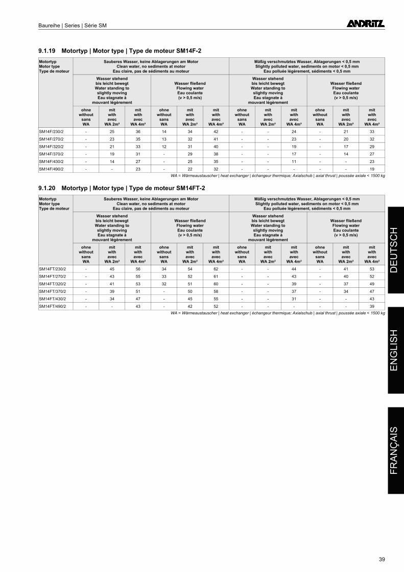
Baureihe | Series | Série SM
DE
UT
SC
HE
NG
LIS
HF
RA
NÇ
AIS
9.1.19 Motortyp | Motor type | Type de moteur SM14F-2
9.1.20 Motortyp | Motor type | Type de moteur SM14FT-2
MotortypMotor typeType de moteur
Sauberes Wasser, keine Ablagerungen am MotorClean water, no sediments at motor
Eau claire, pas de sédiments au moteur
Mäßig verschmutztes Wasser, Ablagerungen < 0,5 mmSlightly polluted water, sediments on motor < 0,5 mm
Eau polluée légèrement, sédiments < 0,5 mm
Wasser stehendbis leicht bewegtWater standing toslightly movingEau stagnate à
mouvant légèrement
Wasser fließendFlowing waterEau coulante(v > 0,5 m/s)
Wasser stehendbis leicht bewegtWater standing to
slightly movingEau stagnate à
mouvant légèrement
Wasser fließendFlowing waterEau coulante(v > 0,5 m/s)
ohnewithout
sansWA
mitwithavec
WA 2m²
mitwithavec
WA 4m²
ohnewithout
sansWA
mitwithavec
WA 2m²
mitwithavec
WA 4m²
ohnewithout
sansWA
mitwithavec
WA 2m²
mitwithavec
WA 4m²
ohnewithout
sansWA
mitwithavec
WA 2m²
mitwithavec
WA 4m²
SM14F/230/2 - 25 36 14 34 42 - - 24 - 21 33
SM14F/270/2 - 23 35 13 32 41 - - 23 - 20 32
SM14F/320/2 - 21 33 12 31 40 - - 19 - 17 29
SM14F/370/2 - 19 31 - 29 38 - - 17 - 14 27
SM14F/430/2 - 14 27 - 25 35 - - 11 - - 23
SM14F/490/2 - - 23 - 22 32 - - - - - 19
WA = Wärmeaustauscher | heat exchanger | échangeur thermique; Axialschub | axial thrust | poussée axiale < 1500 kg
MotortypMotor typeType de moteur
Sauberes Wasser, keine Ablagerungen am MotorClean water, no sediments at motor
Eau claire, pas de sédiments au moteur
Mäßig verschmutztes Wasser, Ablagerungen < 0,5 mmSlightly polluted water, sediments on motor < 0,5 mm
Eau polluée légèrement, sédiments < 0,5 mm
Wasser stehendbis leicht bewegtWater standing toslightly movingEau stagnate à
mouvant légèrement
Wasser fließendFlowing waterEau coulante(v > 0,5 m/s)
Wasser stehendbis leicht bewegtWater standing to
slightly movingEau stagnate à
mouvant légèrement
Wasser fließendFlowing waterEau coulante(v > 0,5 m/s)
ohnewithout
sansWA
mitwithavec
WA 2m²
mitwithavec
WA 4m²
ohnewithout
sansWA
mitwithavec
WA 2m²
mitwithavec
WA 4m²
ohnewithout
sansWA
mitwithavec
WA 2m²
mitwithavec
WA 4m²
ohnewithout
sansWA
mitwithavec
WA 2m²
mitwithavec
WA 4m²
SM14FT/230/2 - 45 56 34 54 62 - - 44 - 41 53
SM14FT/270/2 - 43 55 33 52 61 - - 43 - 40 52
SM14FT/320/2 - 41 53 32 51 60 - - 39 - 37 49
SM14FT/370/2 - 39 51 - 50 58 - - 37 - 34 47
SM14FT/430/2 - 34 47 - 45 55 - - 31 - - 43
SM14FT/490/2 - - 43 - 42 52 - - - - - 39
WA = Wärmeaustauscher | heat exchanger | échangeur thermique; Axialschub | axial thrust | poussée axiale < 1500 kg
39
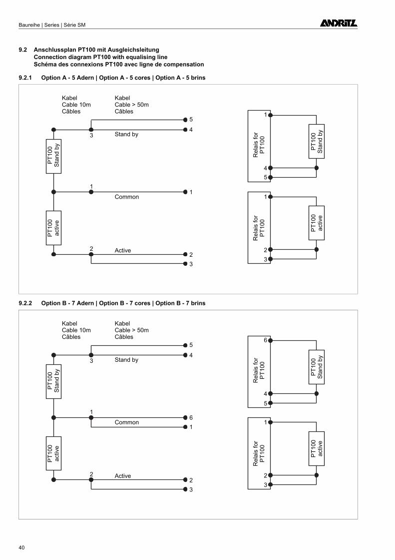
Baureihe | Series | Série SM
9.2 Anschlussplan PT100 mit Ausgleichsleitung Connection diagram PT100 with equalising line Schéma des connexions PT100 avec ligne de compensation
9.2.1 Option A - 5 Adern | Option A - 5 cores | Option A - 5 brins
9.2.2 Option B - 7 Adern | Option B - 7 cores | Option B - 7 brins
KabelCable 10mCâbles
KabelCable > 50mCâbles
PT
100
Sta
nd b
yP
T1
00ac
tive
PT
10
0S
tand
by
PT
10
0a
ctiv
e
Stand by
Common
Active
1
2
3
4
5
1
2
3
Re
lais
for
PT
100
Re
lais
fo
rP
T1
00
1
2
3
4
5
1
KabelCable 10mCâbles
KabelCable > 50mCâbles
PT
100
Sta
nd
by
PT
10
0a
ctiv
e
PT
100
Sta
nd
by
PT
100
activ
e
Stand by
Common
Active
6
2
3
4
5
1
2
3
1
Rel
ais
for
PT
100
Re
lais
for
PT
10
0
6
2
3
4
5
1
40

Baureihe | Series | Série SM
Für Ihre Notizen | For your notes | Pour vos notes
41
DE
UT
SC
HE
NG
LIS
HF
RA
NÇ
AIS

Baureihe | Series | Série SM
Für Ihre Notizen | For your notes | Pour vos notes
42

Te
chn
isch
e Ä
nd
eru
ng
en
vo
rbe
ha
lten
We
re
serv
e t
he
rig
ht
to m
ake
te
chn
ica
l ch
an
ge
sT
ou
s d
roits
ré
serv
és
po
ur
act
ua
lisa
tion
te
chn
iqu
e
4006739/07.11ANDRITZ Ritz GmbH | Güglingstraße 50 | 73529 Schwäbisch Gmünd | GermanyPhone +49 (0) 7171 609-0 | Fax +49 (0) 7171 609-287 | [email protected] | www.ritz.de