Embed Size (px)
Citation preview
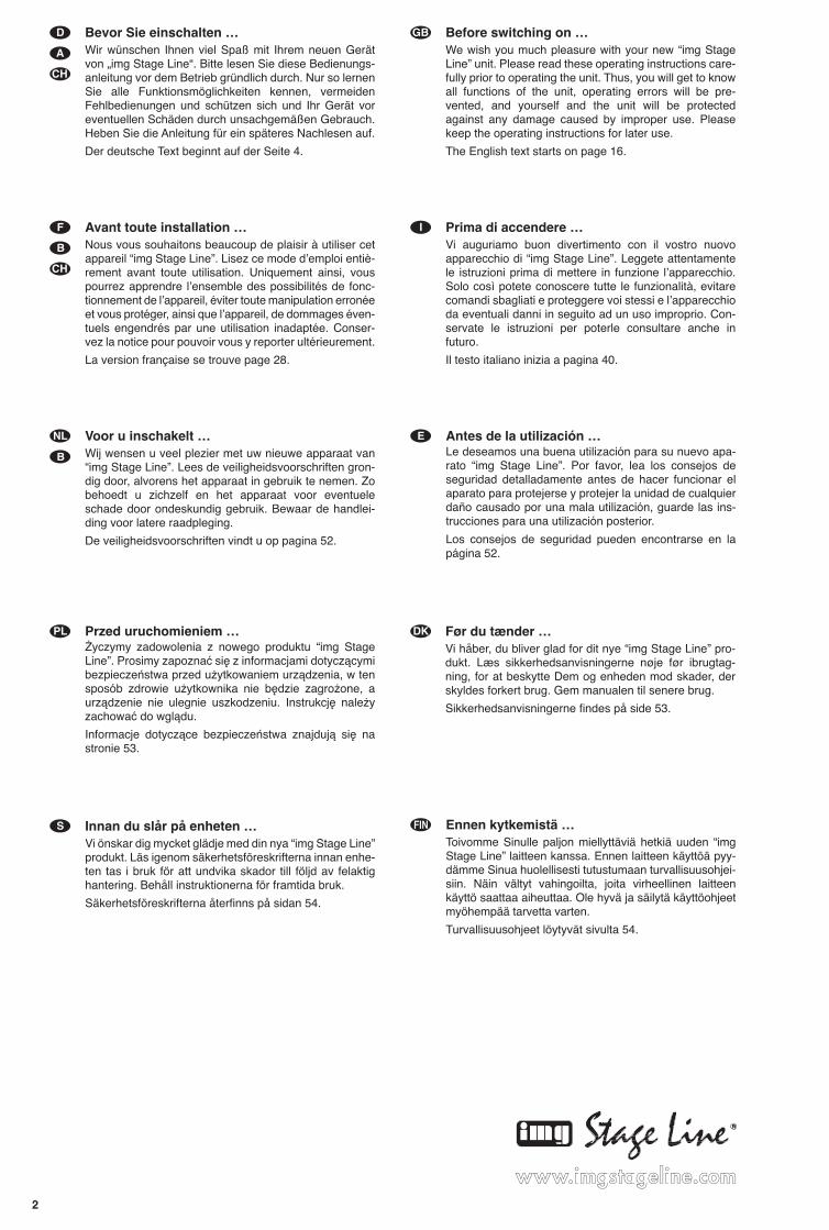
DRM-880LAN Best.-Nr. 17.3750
DRM-880WP Best.-Nr. 17.3760
DIGITALER MATRIX-ROUTERDIGITAL MATRIX ROUTERROUTEUR MATRICIEL NUMÉRIQUEROUTER MATRICE DIGITALE
BEDIENUNGSANLEITUNG • INSTRUCTION MANUAL • MODE D’EMPLOI • ISTRUZIONI PER L’USOVEILIGHEIDSVOORSCHRIFTEN • CONSEJOS DE SEGURIDAD • ŚRODKI BEZPIECZEŃSTWA
SIKKERHEDSOPLYSNINGER • SÄKERHETSFÖRESKRIFTER • TURVALLISUUDESTA
2
wwwwww..iimmggssttaaggeelliinnee..ccoomm
Bevor Sie einschalten …Wir wünschen Ihnen viel Spaß mit Ihrem neuen Gerätvon „img Stage Line“. Bitte lesen Sie diese Bedienungs-anleitung vor dem Betrieb gründlich durch. Nur so lernenSie alle Funktionsmöglichkeiten kennen, vermeidenFehlbedienungen und schützen sich und Ihr Gerät voreventuellen Schäden durch unsachgemäßen Gebrauch.Heben Sie die Anleitung für ein späteres Nachlesen auf.
Der deutsche Text beginnt auf der Seite 4.
Before switching on …We wish you much pleasure with your new “img StageLine” unit. Please read these operating instructions care-fully prior to operating the unit. Thus, you will get to knowall functions of the unit, operating errors will be pre-vented, and yourself and the unit will be protectedagainst any damage caused by improper use. Pleasekeep the oper ating instructions for later use.
The English text starts on page 16.
Avant toute installation …Nous vous souhaitons beaucoup de plaisir à utiliser cetappareil “img Stage Line”. Lisez ce mode dʼemploi entiè-rement avant toute utilisation. Uniquement ainsi, vouspourrez apprendre lʼensemble des possibilités de fonc-tionnement de lʼappareil, éviter toute manipulation erronéeet vous protéger, ainsi que lʼappareil, de dommages éven-tuels engendrés par une utilisation inadaptée. Conser-vez la notice pour pouvoir vous y reporter ultérieurement.
La version française se trouve page 28.
Prima di accendere …Vi auguriamo buon divertimento con il vostro nuovoapparecchio di “img Stage Line”. Leggete attentamentele istruzioni prima di mettere in funzione lʼapparecchio.Solo così potete conoscere tutte le funzionalità, evitarecomandi sbagliati e proteggere voi stessi e lʼapparecchioda eventuali danni in seguito ad un uso improprio. Con-servate le istruzioni per poterle consultare anche infuturo.
Il testo italiano inizia a pagina 40.
D
A
CH
GB
Voor u inschakelt …Wij wensen u veel plezier met uw nieuwe apparaat van“img Stage Line”. Lees de veiligheidsvoorschriften gron-dig door, alvorens het apparaat in gebruik te nemen. Zobehoedt u zichzelf en het apparaat voor eventueleschade door ondeskundig gebruik. Bewaar de handlei-ding voor latere raadpleging.
De veiligheidsvoorschriften vindt u op pagina 52.
Før du tænder …Vi håber, du bliver glad for dit nye “img Stage Line” pro-dukt. Læs sikkerhedsanvisningerne nøje før ibrugtag-ning, for at beskytte Dem og enheden mod skader, derskyldes forkert brug. Gem manualen til senere brug.
Sikkerhedsanvisningerne findes på side 53.
Innan du slår på enheten …Vi önskar dig mycket glädje med din nya “img Stage Line”produkt. Läs igenom säkerhetsföre skrifterna innan en he-ten tas i bruk för att undvika skador till följd av felaktighantering. Behåll instruktionerna för framtida bruk.
Säkerhetsföreskrifterna återfinns på sidan 54.
Ennen kytkemistä …Toivomme Sinulle paljon miellyttäviä hetkiä uuden “imgStage Line” laitteen kanssa. Ennen laitteen käyttöä pyy-dämme Sinua huolellisesti tutustumaan turvallisuusohjei-siin. Näin vältyt vahingoilta, joita virheellinen laitteenkäyttö saattaa aiheuttaa. Ole hyvä ja säilytä käyttöohjeetmyöhempää tarvetta varten.
Turvallisuusohjeet löytyvät sivulta 54.
F
B
CH
I
NL
FIN
B
Antes de la utilización …Le deseamos una buena utilización para su nuevo apa-rato “img Stage Line”. Por favor, lea los consejos deseguridad detalladamente antes de hacer funcionar elaparato para protejerse y protejer la unidad de cualquierdaño causado por una mala utilización, guarde las ins-trucciones para una utilización posterior.
Los consejos de seguridad pueden encontrarse en lapágina 52.
E
DK
S
Przed uruchomieniem …Życzymy zadowolenia z nowego produktu “img StageLine”. Prosimy zapoznać się z informacjami dotyczącymibezpieczeństwa przed użytkowaniem urządzenia, w tensposób zdrowie użytkownika nie będzie zagrożone, aurządzenie nie ulegnie uszkodzeniu. Instrukcję należyzachować do wglądu.
Informacje dotyczące bezpieczeństwa znajdują się nastronie 53.
PL
3
③
④
⑤
②
1 2 3 4 5
6 7 8 9 10 11 12 13 14 15
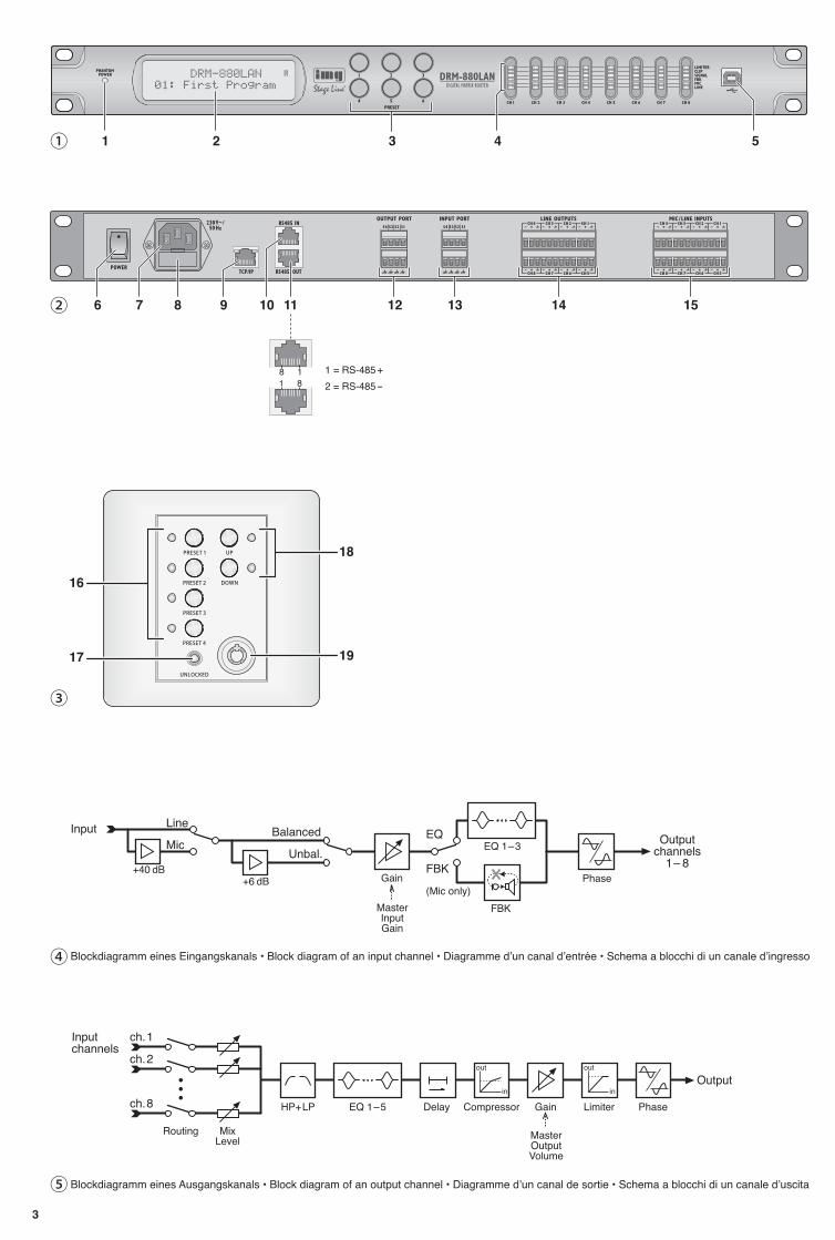
Blockdiagramm eines Eingangskanals • Block diagram of an input channel • Diagramme dʼun canal dʼentrée • Schema a blocchi di un canale dʼingresso
Blockdiagramm eines Ausgangskanals • Block diagram of an output channel • Diagramme dʼun canal de sortie • Schema a blocchi di un canale dʼuscita
16
17
18
19
①
4
D
A
CH
Inhalt1 Übersicht der Bedienelemente und
Anschlüsse . . . . . . . . . . . . . . . . . . . . . 4
1.1 Vorderseite . . . . . . . . . . . . . . . . . . . . . . 4
1.2 Rückseite . . . . . . . . . . . . . . . . . . . . . . . 4
1.3 Bedieneinheit DRM-880WP . . . . . . . . . 5
2 Hinweise für den sicheren Gebrauch 5
3 Einsatzmöglichkeiten . . . . . . . . . . . . . 5
4 Gerät aufstellen und anschließen . . . 5
4.1 Signalquellen . . . . . . . . . . . . . . . . . . . . . 5
4.2 Verstärker oder andere Geräte . . . . . . . 5
4.3 Externe Schaltsignale . . . . . . . . . . . . . . 5
4.4 Zu steuernde Geräte . . . . . . . . . . . . . . . 5
4.5 Bedieneinheit DRM-880WP . . . . . . . . . 5
4.6 Computer . . . . . . . . . . . . . . . . . . . . . . . 5
4.7 Netzanschluss . . . . . . . . . . . . . . . . . . . . 6
5 Bedienung . . . . . . . . . . . . . . . . . . . . . . 6
5.1 Ein- /Ausschalten . . . . . . . . . . . . . . . . . . 6
5.2 Konfiguration wählen . . . . . . . . . . . . . . . 6
5.3 Systemeinstellungen . . . . . . . . . . . . . . . 6
5.3.1 IP-Adresse einstellen . . . . . . . . . . . . . . 6
5.3.2 Schnittstelle wählen . . . . . . . . . . . . . . . 6
5.3.3 Gerätenummer für RS-485 . . . . . . . . . . 6
5.3.4 Schaltkombination abrufen . . . . . . . . . . 7
5.3.5 Schaltkombinationen an Konfigurationenkoppeln . . . . . . . . . . . . . . . . . . . . . . . . . 7
5.4 Status-LEDs . . . . . . . . . . . . . . . . . . . . . 7
5.5 Bedienung über DRM-880WP . . . . . . . . 7
5.5.1 Bedieneinheit einrichten . . . . . . . . . . . . 7
6 Fernbedienung über einen Computer 7
6.1 PC-Software installieren . . . . . . . . . . . . 7
6.1.1 Schnittstellentreiber installieren . . . . . . 7
6.2 PC-Software starten . . . . . . . . . . . . . . . 7
6.2.1 Geräte hinzufügen . . . . . . . . . . . . . . . . . 8
6.2.2 Geräte verbinden oder trennen . . . . . . . 8
6.2.3 Gerät benennen . . . . . . . . . . . . . . . . . . 8
6.2.4 Konfigurationsfenster öffnen . . . . . . . . . 8
6.2.5 Geräte entfernen . . . . . . . . . . . . . . . . . . 8
6.2.6 Gerätekonstellation speichern . . . . . . . . 8
6.2.7 Gerätekonstellation laden . . . . . . . . . . . 8
6.2.8 Schnittstelle wechseln . . . . . . . . . . . . . . 8
6.2.9 ID oder IP-Adresse einstellen . . . . . . . . 8
6.2.10 Programm beenden . . . . . . . . . . . . . . 9
6.3 Ansichten . . . . . . . . . . . . . . . . . . . . . . . 9
6.3.1 Einheit für Signalverzögerung . . . . . . . . 9
6.4 Eingänge konfigurieren . . . . . . . . . . . . . 9
6.4.1 Signalpegel wählen . . . . . . . . . . . . . . . . 9
6.4.2 Signalübertragungsart wählen . . . . . . . 9
6.4.3 Phantomspeisung . . . . . . . . . . . . . . . . . 9
6.4.4 Verstärkung . . . . . . . . . . . . . . . . . . . . . 10
6.4.4.1 Hauptregler „Master Input Gain“ . . . . 10
6.4.5 Klangregelung (EQ) . . . . . . . . . . . . . . 10
6.4.5.1 Frequenzgang . . . . . . . . . . . . . . . . . . 10
6.4.6 Rückkopplungsunterdrückung (FBK) . 10
6.4.7 Phasenumkehr . . . . . . . . . . . . . . . . . . 10
6.5 Ausgänge konfigurieren . . . . . . . . . . . 10
6.5.1 Eingangssignale zuweisen /mischen . . 10
6.5.2 Signalverzögerung . . . . . . . . . . . . . . . 11
6.5.3 Hochpass- und Tiefpassfilter . . . . . . . . 11
6.5.4 Klangregelung . . . . . . . . . . . . . . . . . . . 11
6.5.4.1 Frequenzgang . . . . . . . . . . . . . . . . . . 11
6.5.5 Kompressor . . . . . . . . . . . . . . . . . . . . . 11
6.5.6 Verstärkung . . . . . . . . . . . . . . . . . . . . . 12
6.5.7 Pegelbegrenzung (Limiter) . . . . . . . . . 12
6.5.8 Phasenumkehr . . . . . . . . . . . . . . . . . . 12
6.5.9 Hauptregler . . . . . . . . . . . . . . . . . . . . . 12
6.6 Status-Anzeige . . . . . . . . . . . . . . . . . . 12
6.7 Stummschaltung . . . . . . . . . . . . . . . . . 12
6.8 Kopplung der Kanäle . . . . . . . . . . . . . . 12
6.9 Einstellungen kopieren . . . . . . . . . . . . 13
6.9.1 Einstellungen eines Eingangs kopieren 13
6.9.2 Einstellungen eines Ausgangs kopieren 13
6.10 Ein- und Ausgänge umbenennen . . . . 13
6.11 Verwaltung der Konfigurationen . . . . . 13
6.11.1 Konfiguration auf dem Computer speichern . . . . . . . . . . . . . . . . . . . . . . 13
6.11.2 Konfiguration vom Computer laden . . 13
6.11.3 Konfiguration im Gerät speichern . . . 13
6.11.4 Konfiguration aus dem Gerät laden . 13
6.11.5 Extra-Konfigurationen . . . . . . . . . . . . 13
6.12 Schaltausgänge . . . . . . . . . . . . . . . . . 14
6.12.1 Schaltausgänge umbenennen . . . . . 14
6.12.2 Schaltkombination im Gerät speichern14
6.12.3 Schaltkombination auf dem Computerspeichern . . . . . . . . . . . . . . . . . . . . . . 14
6.12.4 Schaltkombination vom Computer laden . . . . . . . . . . . . . . . . . . . . . . . . . 14
6.13 Schalteingänge . . . . . . . . . . . . . . . . . . 14
6.13.1 Eingänge freigeben oder sperren . . . 14
6.13.2 Logikart (high / low) wählen . . . . . . . . 14
6.13.3 Prioritäten wählen . . . . . . . . . . . . . . . 14
6.14 Schnittstellenmodus wählen . . . . . . . . 15
6.15 Konfigurationsfenster schließen . . . . . 15
7 Technische Daten . . . . . . . . . . . . . . . 15
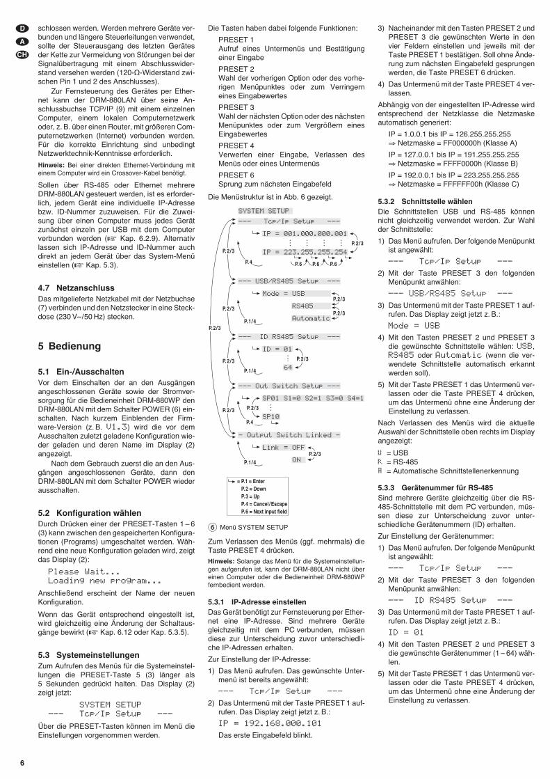
Auf der ausklappbaren Seite 3 finden Sie alle beschriebenen Bedienelemente und An -schlüsse.
1 Übersicht der Bedienelemente und Anschlüsse
1.1 Vorderseite
1 Anzeige PHANTOM POWER; leuchtet beieingeschalteter Phantomspeisung für dieMikrofoneingänge
2 LC-Display
3 Tasten PRESET 1 – 6 zum Abrufen zuvorgespeicherter KonfigurationenZum Aufrufen des Menüs für die Systemein-stellungen die Taste 5 für mehrere Sekundengedrückt halten. Die Funktionen der Tastenfür die Systemeinstellungen sind in Kapitel5.3 beschrieben.
4 Status-LEDs jeweils für die Ein-/Ausgangs-kanäle CH 1 – CH 8
LIMITER – Limiter oder Kompressor aktiv
CLIP – Eingang übersteuert (nach EQ)
SIGNAL – Signal für Ausgangskanal vorhan-den
FBK – Feedback-Unterdrückung aktiv
MIC – Eingang für Mikrofon
LINE – Eingang für Line-Signalquelle
5 USB-Buchse, Typ B, für den Anschluss einesComputers zur Fernsteuerung und zum Kon-figurieren des DRM-880LAN
1.2 Rückseite
6 Netzschalter POWER
7 Netzbuchse zum Anschluss an eine Steck-dose (230 V~/50 Hz) über das beiliegendeNetzkabel
8 Halterung für die Netzsicherung;eine durchgebrannte Sicherung nur durcheine gleichen Typs ersetzen
9 RJ45-Buchse TCP/ IP für den Anschlusseines Computers zur Fernsteuerung desDRM-880LAN über Ethernet; die beidenLEDs über der Buchse signalisieren den Ver-bindungsaufbau und den Datenverkehr
10 RJ45-Buchse RS485 IN für den Anschlusseines Computers zur Fernsteuerung oder derFernbedieneinheit DRM-880WP (Abb. 3)
11 RJ45-Buchse RS485 OUT für den Anschlusseines weiteren zu steuernden Gerätes beiFernsteuerung durch einen Computer überdie Buchse RS485 IN (10)
12 Schaltausgänge S1 – S4 als Schraubklem-men*
13 Schalteingänge S1 – S4 als Schraubklem-men* zum Abrufen zuvor gespeicherter Extra-Konfigurationen
14 symmetrisch beschaltete Audiosignal-Aus-gänge CH 1 – CH 8 als Schraubklemmen*
15 symmetrisch beschaltete Audiosignal-Ein-gänge CH 1 – CH 8 als Schraubklemmen*
* Zum bequemeren Anschluss kann jeweils eine kom-plette Klemmenreihe vom Gerät abgezogen werden.
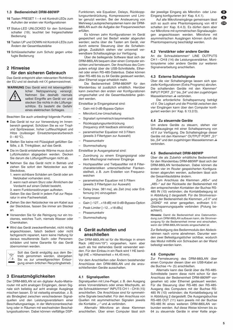
1.3 Bedieneinheit DRM-880WP
16 Tasten PRESET 1 – 4 mit Kontroll-LEDs zumAufrufen der ersten vier Konfigurationen
17 Status-LED UNLOCKED für den Schlüssel-schalter (19); leuchtet bei freigeschalteterBedienung
18 Tasten UP und DOWN mit Kontroll-LEDs zumÄndern der Gesamtlautstärke
19 Schlüsselschalter zum Schutz gegen unbe-fugte Bedienung
2 Hinweise für den sicheren Gebrauch
Das Gerät entspricht allen relevanten Richt liniender EU und ist deshalb mit � gekennzeichnet.
Beachten Sie auch unbedingt folgende Punkte:
� Das Gerät ist nur zur Verwendung im Innen -bereich geeignet. Schützen Sie es vor Tropf-und Spritzwas ser, hoher Luftfeuchtigkeit undHitze (zulässiger Einsatztemperaturbereich0 – 40 °C).
� Stellen Sie keine mit Flüssigkeit gefüllten Ge -fäße, z. B. Trinkgläser, auf das Gerät.
� Die im Gerät entstehende Wärme muss durchLuftzirkulation abgegeben werden. DeckenSie darum die Lüftungsöffnungen nicht ab.
� Nehmen Sie das Gerät nicht in Betrieb undziehen Sie sofort den Netzstecker aus derSteckdose,1. wenn sichtbare Schäden am Gerät oder am
Netzkabel vorhanden sind,2. wenn nach einem Sturz oder Ähnlichem der
Verdacht auf einen Defekt besteht,3. wenn Funktionsstörungen auftreten.Geben Sie das Gerät in jedem Fall zur Repa-ratur in eine Fachwerkstatt.
� Ziehen Sie den Netzstecker nie am Kabel ausder Steckdose, fassen Sie immer am Steckeran.
� Verwenden Sie für die Reinigung nur ein tro-ckenes, weiches Tuch, niemals Wasser oderChemikalien.
� Wird das Gerät zweckentfremdet, nicht richtigangeschlossen, falsch be dient oder nichtfachgerecht repariert, kann keine Haftung fürdaraus resultierende Sach- oder Personen-schäden und keine Garantie für das Gerätübernommen werden.
3 EinsatzmöglichkeitenDer DRM-880LAN ist ein digitaler Audio-Matrix-router mit acht analogen Eingängen, deren Sig-nale sich beliebig auf acht analoge Ausgängemischen lassen. Er ist vielseitig einsetzbar, z. B.als Bindeglied zwischen verschiedenen Signal-quellen und den Leistungsverstärkern einerBeschallungsanlage, in der Mehrzonenbeschal-lung oder in Räumen mit wechselnden Be schal-lungssituationen. Dabei können vielfältige DSP-
Funktionen, wie Equalizer, Delays, Rückkopp-lungsunterdrückung, Kompressoren und Limi-ter genutzt werden. Bei der Ansteuerung vonMehrweg-Lautsprechersystemen kann der DRM-880LAN auch die Aufgabe der Frequenz weichenerfüllen.
Es können zehn Konfigurationen im Gerätgespeichert und bei Bedarf wieder abgerufenwerden; sechs über die Tasten am Gerät, vierdurch externe Steuerung über die Schaltein-gänge. Zusätzlich stehen vier universell ver-wendbare Schaltausgänge zur Verfügung.
Über die beiliegende Software lässt sich derDRM-880LAN bequem über einen Computer ein-richten und fernsteuern. Der Anschluss des Com-puters erfolgt über die USB-Schnittstelle, Ether-net oder einen RS-485-Datenbus. Dabei könnenüber RS-485 bis zu 64 Geräte gesteuert werden,über Ethernet sogar erheblich mehr.
Die Bedieneinheit DRM-880WP für denWandeinbau ist zusätzlich erhältlich. Hierüberkann zwischen den ersten vier Konfigurationenumgeschaltet und die Gesamtlautstärke geän-dert werden.
Einstellbar je Eingangskanal sind:
– Gain mit 0-dB-Bypass-Option
– Mikrofon/Line-Umschaltung
– Signalart symmetrisch/asymmetrisch
– Rückkopplungsunterdrückung (frequency shift feedback eliminator)
– parametrischer Equalizer mit 3 Filtern (jeweils 3 Filtertypen zur Auswahl)
– Phasenumkehr
– Stummschaltung
Einstellbar je Ausgangskanal sind:
– Zuordnung zu einem Eingangssignal oderdem Mischsignal mehrerer Eingänge
– Hochpassfilter und Tiefpassfilter mit 8 Filter-charakteristiken unterschiedlicher Flanken -steilheit, z. B. zum Erstellen von Frequenz -weichen
– parametrischer Equalizer mit 5 Filtern (jeweils 3 Filtertypen zur Auswahl)
– Delay [max. 381 ms], als Zeit (ms) oder Ent-fernung (m) einzugeben
– Kompressor
– Gain [-127...+18 dB] mit 0-dB-Bypass-Option
– Peak-Limiter [-12...+18 dBu]
– Phasenumkehr
– Stummschaltung
4 Gerät aufstellen undanschließen
Der DRM-880LAN ist für die Montage in einemRack (482 mm / 19″) vorgesehen, kann aberauch als frei stehendes Gerät verwendet wer-den. Für den Einbau in ein Rack wird 1 HE benö-tigt (HE = Höheneinheit = 44,45 mm).
Vor dem Anschließen oder Ändern bestehenderAnschlüsse den DRM-880LAN und die anzu-schließenden Geräte ausschalten.
4.1 SignalquellenSignalquellen mit Line-Pegel, z. B. den Ausgangeines Vorverstärkers oder eines Mischpults, andie Schraubklemmen* INPUTS CH 1 – CH 8 (15)anschließen. Die Anschlüsse sind für symmetri-sche Signale beschaltet. Für den Anschluss vonQuellen mit asymmetrischen Signalen jeweilsdie Kontakte „-“ und verbinden.
Alternativ Mikrofone an diese Klemmenanschließen. Über einen Computer lässt sich
der jeweilige Eingang als Mikrofon- oder Line-Eingang konfigurieren (� Kap. 6.4.1).
Auf alle Mikrofoneingänge gemeinsam lässtsich so auch eine Phantomspeisung von 48 Vschalten (� Kap. 6.4.3). Es dürfen dann abernur Mikrofone mit symmetrischen Signalausgän-gen angeschlossen werden. Mikrofone mitasymmetrischen Ausgängen können durch diePhantomspannung beschädigt werden.
4.2 Verstärker oder andere GeräteAn die Schraubklemmen* LINE OUTPUTSCH 1 – CH 8 (14) die Leistungsverstärker, Moni-torsysteme oder andere Geräte zur weiterenSignalverarbeitung anschließen.
4.3 Externe SchaltsignaleÜber die vier Schalteingänge lassen sich spe-zielle Konfigurationen (Extra Programs) abrufen.Die schaltenden Geräte mit den Klemmen*INPUT PORT „S1“ bis „S4“ und den zugehörigenMasseklemmen verbinden.
Die erforderliche Schaltspannung beträgt+5 V. Die Logikart und die Priorität zwischen denvier Eingängen kann über den Computer konfi-guriert werden (� Kap. 6.13.2/ 3).
4.4 Zu steuernde GeräteUm andere Geräte zu steuern, stehen vierSchaltausgänge mit einer Schaltspannung von+5 V zur Verfügung. Die Schalteingänge dieserGeräte mit den Klemmen* OUTPUT PORT „S1“bis „S4“ und den zugehörigen Masseklemmenverbinden.
4.5 Bedieneinheit DRM-880WPÜber die als Zubehör erhältliche Bedieneinheitfür den Wandeinbau DRM-880WP lässt sich derDRM-880LAN fernbedienen. Dabei können dieersten vier im Router gespeicherten Konfigura-tionen abgerufen werden, außerdem lässt sichdie Gesamtlautstärke ändern.
Zum Anschluss die Klemmen „485+“ und„485-“ auf der Rückseite der Bedieneinheit mitden entsprechenden Kontakten der Buchse RS-485 IN (10) verbinden; die Kontaktbelegung istin Abbildung 2 dargestellt. Für die Stromversor-gung der Bedieneinheit die Klemmen „+5 V“ und„DGND“ mit einer geregelten, erdfreien 5-V-Gleich span nungsquelle verbinden (Polung be -achten!).
Hinweis: Damit die Bedieneinheit eine Datenverbin-dung zum DRM-880LAN aufbauen kann, die Stromver-sorgung für die Bedieneinheit immer erst einschalten,wenn der DRM-880LAN bereits eingeschaltet ist.
Zur Befestigung des Bedienmoduls den Abdeck-rahmen nach vorne abnehmen. Darunter wer-den zwei Befestigungslöcher sichtbar, wodurchdas Modul mithilfe von Schrauben an der Wandbefestigt werden kann.
4.6 ComputerZur Fernsteuerung des DRM-880LAN übereinen Computer diesen über ein USB-Kabel andie Buchse (5) anschließen.
Alternativ kann das Gerät über die RS-485-Schnittstelle (wenn diese nicht schon für denAnschluss der Bedieneinheit DRM-880WP vor-gesehen ist) oder Ethernet gesteuert werden.Für die Steuerung über RS-485 den RS-485-Ausgang des Computers mit der Buchse RS-485 IN (10) verbinden; die Kontaktbelegung istin Abbildung 2 dargestellt. Die AusgangsbuchseRS-485 OUT (11) kann jeweils mit der BuchseRS-485 IN eines weiteren DRM-880LAN ver-bunden werden. Auf diese Weise können bis zu64 zu steuernde Geräte in einer Kette ange-
Soll das Gerät endgültig aus dem Be -trieb genommen werden, übergebenSie es zur umweltgerechten Entsor-gung einem örtlichen Recyclingbetrieb.
WARNUNG Das Gerät wird mit lebensge fähr -licher Netzspannung versorgt.Nehmen Sie deshalb niemalsselbst Eingriffe am Gerät vor undstecken Sie nichts in die Lüftungs-schlitze. Es besteht die Gefahreines elektrischen Schlages.
D
A
CH
5
schlossen werden. Werden mehrere Geräte ver-bunden und längere Steuerleitungen verwendet,sollte der Steuerausgang des letzten Gerätesder Kette zur Vermeidung von Störungen bei derSignalübertragung mit einem Abschlusswider-stand versehen werden (120-Ω-Widerstand zwi-schen Pin 1 und 2 des Anschlusses).
Zur Fernsteuerung des Gerätes per Ether-net kann der DRM-880LAN über seine An -schlussbuchse TCP/ IP (9) mit einem einzelnenComputer, einem lokalen Computernetzwerkoder, z. B. über einen Router, mit größeren Com-puternetzwerken (Internet) verbunden werden.Für die korrekte Einrichtung sind unbedingtNetzwerktechnik-Kenntnisse erforderlich.
Hinweis: Bei einer direkten Ethernet-Verbindung miteinem Computer wird ein Crossover-Kabel benötigt.
Sollen über RS-485 oder Ethernet mehrereDRM-880LAN gesteuert werden, ist es erforder-lich, jedem Gerät eine individuelle IP-Adressebzw. ID-Nummer zuzuweisen. Für die Zuwei-sung über einen Computer muss jedes Gerätzunächst einzeln per USB mit dem Computerverbunden werden (� Kap. 6.2.9). Alternativlassen sich IP-Adresse und ID-Nummer auchdirekt an jedem Gerät über das System-Menüeinstellen (� Kap. 5.3).
4.7 NetzanschlussDas mitgelieferte Netzkabel mit der Netzbuchse(7) verbinden und den Netzstecker in eine Steck-dose (230 V~/50 Hz) stecken.
5 Bedienung
5.1 Ein-/AusschaltenVor dem Einschalten der an den Ausgängenangeschlossenen Geräte sowie der Stromver-sorgung für die Bedieneinheit DRM-880WP denDRM-880LAN mit dem Schalter POWER (6) ein-schalten. Nach kurzem Einblenden der Firm-ware-Version (z. B. V1.3) wird die vor demAusschalten zuletzt geladene Konfiguration wie-der geladen und deren Name im Display (2)angezeigt.
Nach dem Gebrauch zuerst die an den Aus-gängen angeschlossenen Geräte, dann denDRM-880LAN mit dem Schalter POWER wiederausschalten.
5.2 Konfiguration wählenDurch Drücken einer der PRESET-Tasten 1 – 6(3) kann zwischen den gespeicherten Konfigura-tionen (Programs) umgeschaltet werden. Wäh-rend eine neue Konfiguration geladen wird, zeigtdas Display (2):
Please Wait...Loading new program...
Anschließend erscheint der Name der neuenKonfiguration.
Wenn das Gerät entsprechend eingestellt ist,wird gleichzeitig eine Änderung der Schaltaus-gänge bewirkt (� Kap. 6.12 oder Kap. 5.3.5).
5.3 SystemeinstellungenZum Aufrufen des Menüs für die Systemeinstel-lungen die PRESET-Taste 5 (3) länger als5 Sekunden gedrückt halten. Das Display (2)zeigt jetzt:
SYSTEM SETUP--- Tcp/Ip Setup ---
Über die PRESET-Tasten können im Menü dieEinstellungen vorgenommen werden.
Die Tasten haben dabei folgende Funktionen:
PRESET 1Aufruf eines Untermenüs und Bestätigungeiner Eingabe
PRESET 2Wahl der vorherigen Option oder des vorhe-rigen Menüpunktes oder zum Verringerneines Eingabewertes
PRESET 3Wahl der nächsten Option oder des nächstenMenüpunktes oder zum Vergrößern einesEingabewertes
PRESET 4Verwerfen einer Eingabe, Verlassen desMenüs oder eines Untermenüs
PRESET 6Sprung zum nächsten Eingabefeld
Die Menüstruktur ist in Abb. 6 gezeigt.
Zum Verlassen des Menüs (ggf. mehrmals) dieTaste PRESET 4 drücken. Hinweis: Solange das Menü für die Systemeinstellun-gen aufgerufen ist, kann der DRM-880LAN nicht übereinen Computer oder die Bedieneinheit DRM-880WPfernbedient werden.
5.3.1 IP-Adresse einstellenDas Gerät benötigt zur Fernsteuerung per Ether-net eine IP-Adresse. Sind mehrere Gerätegleichzeitig mit dem PC verbunden, müssendiese zur Unterscheidung zuvor unterschiedli-che IP-Adressen erhalten.
Zur Einstellung der IP-Adresse:
1) Das Menü aufrufen. Das gewünschte Unter-menü ist bereits angewählt:
--- Tcp/Ip Setup ---
2) Das Untermenü mit der Taste PRESET 1 auf-rufen. Das Display zeigt jetzt z. B.:
IP = 192.168.000.101
Das erste Eingabefeld blinkt.
3) Nacheinander mit den Tasten PRESET 2 undPRESET 3 die gewünschten Werte in denvier Feldern einstellen und jeweils mit derTaste PRESET 1 bestätigen. Soll ohne Ände-rung zum nächsten Eingabefeld gesprungenwerden, die Taste PRESET 6 drücken.
4) Das Untermenü mit der Taste PRESET 4 ver-lassen.
Abhängig von der eingestellten IP-Adresse wirdentsprechend der Netzklasse die Netzmaskeautomatisch generiert:
IP = 1.0.0.1 bis IP = 126.255.255.255⇒ Netzmaske = FF000000h (Klasse A)
IP = 127.0.0.1 bis IP = 191.255.255.255⇒ Netzmaske = FFFF0000h (Klasse B)
IP = 192.0.0.1 bis IP = 223.255.255.255⇒ Netzmaske = FFFFFF00h (Klasse C)
5.3.2 Schnittstelle wählenDie Schnittstellen USB und RS-485 könnennicht gleichzeitig verwendet werden. Zur Wahlder Schnittstelle:
1) Das Menü aufrufen. Der folgende Menüpunktist angewählt:
--- Tcp/Ip Setup ---
2) Mit der Taste PRESET 3 den folgendenMenüpunkt anwählen:
--- USB/RS485 Setup ---
3) Das Untermenü mit der Taste PRESET 1 auf-rufen. Das Display zeigt jetzt z. B.:
Mode = USB
4) Mit den Tasten PRESET 2 und PRESET 3die gewünschte Schnittstelle wählen: USB,RS485 oder Automatic (wenn die ver-wendete Schnittstelle automatisch erkanntwerden soll).
5) Mit der Taste PRESET 1 das Untermenü ver-lassen oder die Taste PRESET 4 drücken,um das Untermenü ohne eine Änderung derEinstellung zu verlassen.
Nach Verlassen des Menüs wird die aktuelleAuswahl der Schnittstelle oben rechts im Displayangezeigt:
= USB= RS-485= Automatische Schnittstellenerkennung
5.3.3 Gerätenummer für RS-485Sind mehrere Geräte gleichzeitig über die RS-485-Schnittstelle mit dem PC verbunden, müs-sen diese zur Unterscheidung zuvor unter-schiedliche Gerätenummern (ID) erhalten.
Zur Einstellung der Gerätenummer:
1) Das Menü aufrufen. Der folgende Menüpunktist angewählt:
--- Tcp/Ip Setup ---
2) Mit der Taste PRESET 3 den folgendenMenüpunkt anwählen:
--- ID RS485 Setup ---
3) Das Untermenü mit der Taste PRESET 1 auf-rufen. Das Display zeigt jetzt z. B.:
ID = 01
4) Mit den Tasten PRESET 2 und PRESET 3die gewünschte Gerätenummer (1 – 64) wäh-len.
5) Mit der Taste PRESET 1 das Untermenü ver-lassen oder die Taste PRESET 4 drücken,um das Untermenü ohne eine Änderung derEinstellung zu verlassen.
⑥ Menü SYSTEM SETUP
D
A
CH
6
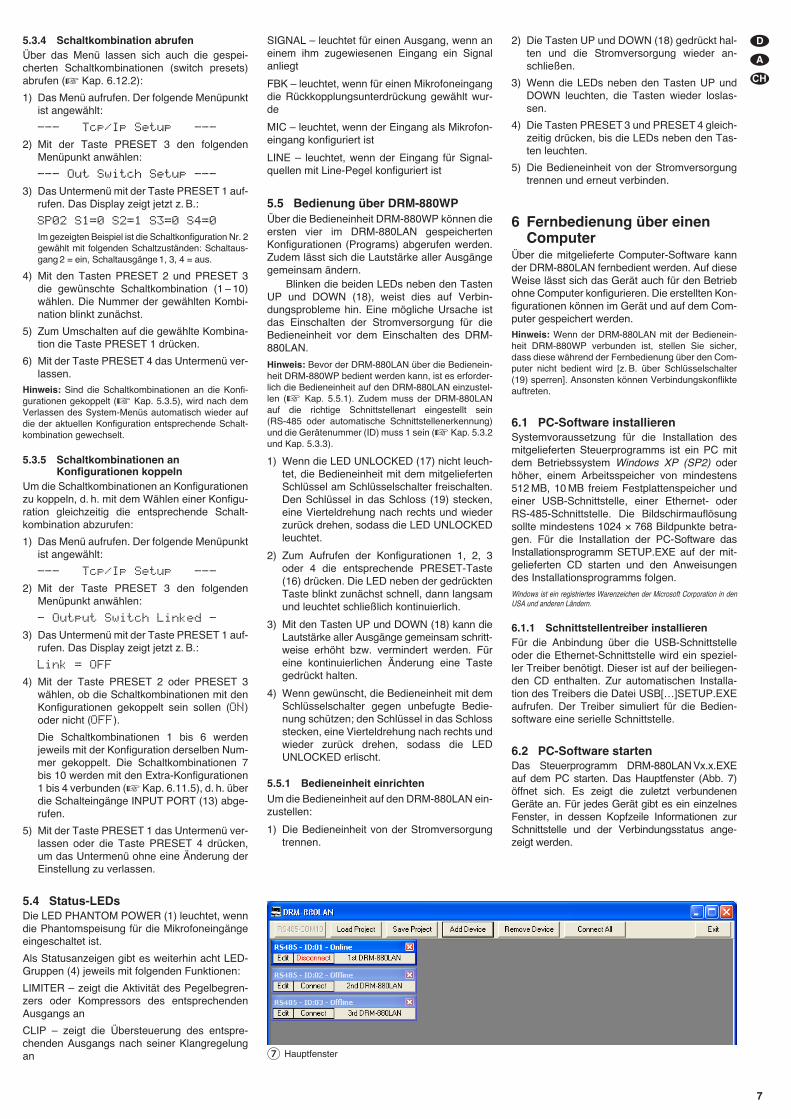
5.3.4 Schaltkombination abrufenÜber das Menü lassen sich auch die gespei-cherten Schaltkombinationen (switch presets)abrufen (� Kap. 6.12.2):
1) Das Menü aufrufen. Der folgende Menüpunktist angewählt:
--- Tcp/Ip Setup ---
2) Mit der Taste PRESET 3 den folgendenMenüpunkt anwählen:
--- Out Switch Setup ---
3) Das Untermenü mit der Taste PRESET 1 auf-rufen. Das Display zeigt jetzt z. B.:
SP02 S1=0 S2=1 S3=0 S4=0
Im gezeigten Beispiel ist die Schaltkonfiguration Nr. 2gewählt mit folgenden Schaltzuständen: Schalt aus -gang 2 = ein, Schaltausgänge 1, 3, 4 = aus.
4) Mit den Tasten PRESET 2 und PRESET 3die gewünschte Schaltkombination (1 – 10)wählen. Die Nummer der gewählten Kombi-nation blinkt zunächst.
5) Zum Umschalten auf die gewählte Kombina-tion die Taste PRESET 1 drücken.
6) Mit der Taste PRESET 4 das Untermenü ver-lassen.
Hinweis: Sind die Schaltkombinationen an die Konfi-gurationen gekoppelt (� Kap. 5.3.5), wird nach demVerlassen des System-Menüs automatisch wieder aufdie der aktuellen Konfiguration entsprechende Schalt-kombination gewechselt.
5.3.5 Schaltkombinationen anKonfigurationen koppeln
Um die Schaltkombinationen an Konfigurationenzu koppeln, d. h. mit dem Wählen einer Konfigu-ration gleichzeitig die entsprechende Schalt-kombination abzurufen:
1) Das Menü aufrufen. Der folgende Menüpunktist angewählt:
--- Tcp/Ip Setup ---
2) Mit der Taste PRESET 3 den folgendenMenüpunkt anwählen:
- Output Switch Linked -
3) Das Untermenü mit der Taste PRESET 1 auf-rufen. Das Display zeigt jetzt z. B.:
Link = OFF
4) Mit der Taste PRESET 2 oder PRESET 3wählen, ob die Schaltkombinationen mit denKonfigurationen gekoppelt sein sollen (ON)oder nicht (OFF).
Die Schaltkombinationen 1 bis 6 werdenjeweils mit der Konfiguration derselben Num-mer gekoppelt. Die Schaltkombinationen 7bis 10 werden mit den Extra-Konfigurationen1 bis 4 verbunden (� Kap. 6.11.5), d. h. überdie Schalteingänge INPUT PORT (13) abge-rufen.
5) Mit der Taste PRESET 1 das Untermenü ver-lassen oder die Taste PRESET 4 drücken,um das Untermenü ohne eine Änderung derEinstellung zu verlassen.
5.4 Status-LEDsDie LED PHANTOM POWER (1) leuchtet, wenndie Phantomspeisung für die Mikrofoneingängeeingeschaltet ist.
Als Statusanzeigen gibt es weiterhin acht LED-Gruppen (4) jeweils mit folgenden Funktionen:
LIMITER – zeigt die Aktivität des Pegelbegren-zers oder Kompressors des entsprechendenAusgangs an
CLIP – zeigt die Übersteuerung des entspre-chenden Ausgangs nach seiner Klangregelungan
SIGNAL – leuchtet für einen Ausgang, wenn aneinem ihm zugewiesenen Eingang ein Signalanliegt
FBK – leuchtet, wenn für einen Mikrofoneingangdie Rückkopplungsunterdrückung gewählt wur -de
MIC – leuchtet, wenn der Eingang als Mikrofon-eingang konfiguriert ist
LINE – leuchtet, wenn der Eingang für Signal-quellen mit Line-Pegel konfiguriert ist
5.5 Bedienung über DRM-880WPÜber die Bedieneinheit DRM-880WP können dieersten vier im DRM-880LAN gespeichertenKonfigurationen (Programs) abgerufen werden.Zudem lässt sich die Lautstärke aller Ausgängegemeinsam ändern.
Blinken die beiden LEDs neben den TastenUP und DOWN (18), weist dies auf Verbin-dungsprobleme hin. Eine mögliche Ursache istdas Einschalten der Stromversorgung für dieBe dieneinheit vor dem Einschalten des DRM-880LAN.
Hinweis: Bevor der DRM-880LAN über die Bedienein-heit DRM-880WP bedient werden kann, ist es erforder-lich die Bedieneinheit auf den DRM-880LAN einzustel-len (� Kap. 5.5.1). Zudem muss der DRM-880LANauf die richtige Schnittstellenart eingestellt sein(RS-485 oder automatische Schnittstellenerkennung)und die Gerätenummer (ID) muss 1 sein (� Kap. 5.3.2und Kap. 5.3.3).
1) Wenn die LED UNLOCKED (17) nicht leuch-tet, die Bedieneinheit mit dem mitgeliefertenSchlüssel am Schlüsselschalter freischalten.Den Schlüssel in das Schloss (19) stecken,eine Vierteldrehung nach rechts und wiederzurück drehen, sodass die LED UNLOCKEDleuchtet.
2) Zum Aufrufen der Konfigurationen 1, 2, 3oder 4 die entsprechende PRESET-Taste(16) drücken. Die LED neben der gedrücktenTaste blinkt zunächst schnell, dann langsamund leuchtet schließlich kontinuierlich.
3) Mit den Tasten UP und DOWN (18) kann dieLautstärke aller Ausgänge gemeinsam schritt-weise er höht bzw. vermindert werden. Füreine kontinuierlichen Änderung eine Tastegedrückt halten.
4) Wenn gewünscht, die Bedieneinheit mit demSchlüsselschalter gegen unbefugte Bedie-nung schützen; den Schlüssel in das Schlossstecken, eine Vierteldrehung nach rechts undwieder zurück drehen, sodass die LEDUNLOCKED erlischt.
5.5.1 Bedieneinheit einrichtenUm die Bedieneinheit auf den DRM-880LAN ein-zustellen:
1) Die Bedieneinheit von der Stromversorgungtrennen.
2) Die Tasten UP und DOWN (18) gedrückt hal-ten und die Stromversorgung wieder an -schließen.
3) Wenn die LEDs neben den Tasten UP undDOWN leuchten, die Tasten wieder loslas-sen.
4) Die Tasten PRESET 3 und PRESET 4 gleich-zeitig drücken, bis die LEDs neben den Tas-ten leuchten.
5) Die Bedieneinheit von der Stromversorgungtrennen und erneut verbinden.
6 Fernbedienung über einenComputer
Über die mitgelieferte Computer-Software kannder DRM-880LAN fernbedient werden. Auf dieseWeise lässt sich das Gerät auch für den Betriebohne Computer konfigurieren. Die erstellten Kon-figurationen können im Gerät und auf dem Com-puter gespeichert werden.
Hinweis: Wenn der DRM-880LAN mit der Bedienein-heit DRM-880WP verbunden ist, stellen Sie sicher,dass diese während der Fernbedienung über den Com-puter nicht bedient wird [z. B. über Schlüsselschalter(19) sperren]. Ansonsten können Verbindungskonflikteauftreten.
6.1 PC-Software installierenSystemvoraussetzung für die Installation desmitgelieferten Steuerprogramms ist ein PC mitdem Betriebssystem Windows XP (SP2) oderhöher, einem Arbeitsspeicher von mindestens512 MB, 10 MB freiem Festplattenspeicher undeiner USB-Schnittstelle, einer Ethernet- oderRS-485-Schnittstelle. Die Bildschirmauflösungsollte mindestens 1024 × 768 Bildpunkte betra-gen. Für die Installation der PC-Software dasInstallationsprogramm SETUP.EXE auf der mit-gelieferten CD starten und den Anweisungendes Installationsprogramms folgen.
Windows ist ein registriertes Warenzeichen der Microsoft Corporation in denUSA und anderen Ländern.
6.1.1 Schnittstellentreiber installierenFür die Anbindung über die USB-Schnittstelleoder die Ethernet-Schnittstelle wird ein speziel-ler Treiber benötigt. Dieser ist auf der beiliegen-den CD enthalten. Zur automatischen Installa-tion des Treibers die Datei USB[…]SETUP.EXEaufrufen. Der Treiber simuliert für die Bedien -software eine serielle Schnittstelle.
6.2 PC-Software startenDas Steuerprogramm DRM-880LAN Vx.x.EXEauf dem PC starten. Das Hauptfenster (Abb. 7)öffnet sich. Es zeigt die zuletzt verbundenenGeräte an. Für jedes Gerät gibt es ein einzelnesFenster, in dessen Kopfzeile Informationen zurSchnittstelle und der Verbindungsstatus ange-zeigt werden.
D
A
CH
7
⑦ Hauptfenster
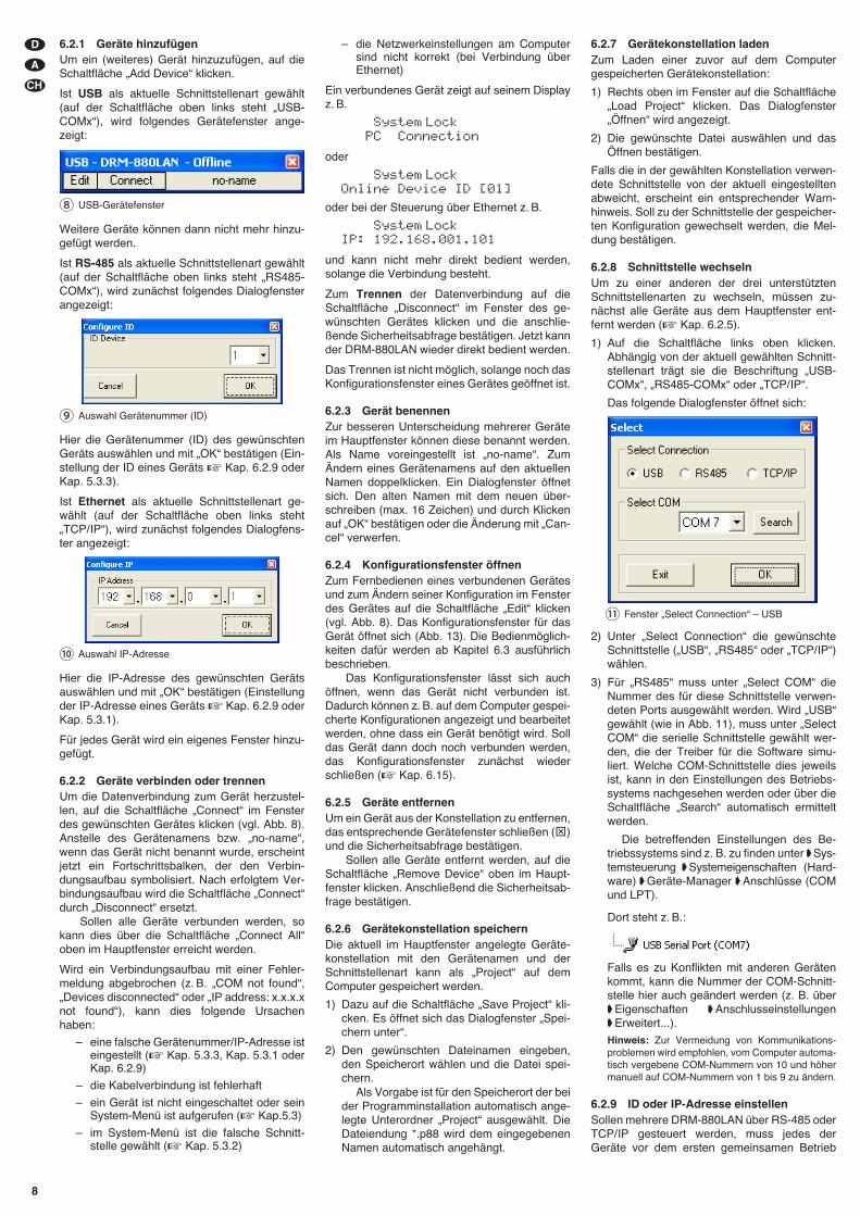
6.2.1 Geräte hinzufügenUm ein (weiteres) Gerät hinzuzufügen, auf dieSchaltfläche „Add Device“ klicken.
Ist USB als aktuelle Schnittstellenart gewählt(auf der Schaltfläche oben links steht „USB-COMx“), wird folgendes Gerätefenster ange-zeigt:
Weitere Geräte können dann nicht mehr hinzu-gefügt werden.
Ist RS-485 als aktuelle Schnittstellenart ge wählt(auf der Schaltfläche oben links steht „RS485-COMx“), wird zunächst folgendes Dialogfensterangezeigt:
Hier die Gerätenummer (ID) des gewünschtenGeräts auswählen und mit „OK“ bestätigen (Ein-stellung der ID eines Geräts � Kap. 6.2.9 oderKap. 5.3.3).
Ist Ethernet als aktuelle Schnittstellenart ge -wählt (auf der Schaltfläche oben links steht„TCP/ IP“), wird zunächst folgendes Dialogfens-ter angezeigt:
Hier die IP-Adresse des gewünschten Gerätsauswählen und mit „OK“ bestätigen (Einstellungder IP-Adresse eines Geräts � Kap. 6.2.9 oderKap. 5.3.1).
Für jedes Gerät wird ein eigenes Fenster hinzu-gefügt.
6.2.2 Geräte verbinden oder trennenUm die Datenverbindung zum Gerät herzustel-len, auf die Schaltfläche „Connect“ im Fensterdes gewünschten Gerätes klicken (vgl. Abb. 8).Anstelle des Gerätenamens bzw. „no-name“,wenn das Gerät nicht benannt wurde, erscheintjetzt ein Fortschrittsbalken, der den Verbin-dungsaufbau symbolisiert. Nach erfolgtem Ver-bindungsaufbau wird die Schaltfläche „Connect“durch „Disconnect“ ersetzt.
Sollen alle Geräte verbunden werden, sokann dies über die Schaltfläche „Connect All“oben im Hauptfenster erreicht werden.
Wird ein Verbindungsaufbau mit einer Fehler-meldung abgebrochen (z. B. „COM not found“,„Devices disconnected“ oder „IP address: x.x.x.xnot found“), kann dies folgende Ursachenhaben:
– eine falsche Gerätenummer/ IP-Adresse isteingestellt (� Kap. 5.3.3, Kap. 5.3.1 oderKap. 6.2.9)
– die Kabelverbindung ist fehlerhaft
– ein Gerät ist nicht eingeschaltet oder seinSystem-Menü ist aufgerufen (� Kap.5.3)
– im System-Menü ist die falsche Schnitt-stelle gewählt (� Kap. 5.3.2)
– die Netzwerkeinstellungen am Computersind nicht korrekt (bei Verbindung überEthernet)
Ein verbundenes Gerät zeigt auf seinem Displayz. B.
System LockPC Connection
oder
System LockOnline Device ID [01]
oder bei der Steuerung über Ethernet z. B.
System LockIP: 192.168.001.101
und kann nicht mehr direkt bedient werden,solange die Verbindung besteht.
Zum Trennen der Datenverbindung auf dieSchaltfläche „Disconnect“ im Fenster des ge -wünschten Gerätes klicken und die an schlie-ßende Sicherheitsabfrage bestätigen. Jetzt kannder DRM-880LAN wieder direkt bedient werden.
Das Trennen ist nicht möglich, solange noch dasKonfigurationsfenster eines Gerätes geöffnet ist.
6.2.3 Gerät benennenZur besseren Unterscheidung mehrerer Geräteim Hauptfenster können diese benannt werden.Als Name voreingestellt ist „no-name“. ZumÄndern eines Gerätenamens auf den aktuellenNamen doppelklicken. Ein Dialogfenster öffnetsich. Den alten Namen mit dem neuen über-schreiben (max. 16 Zeichen) und durch Klickenauf „OK“ bestätigen oder die Änderung mit „Can-cel“ verwerfen.
6.2.4 Konfigurationsfenster öffnenZum Fernbedienen eines verbundenen Gerätesund zum Ändern seiner Konfiguration im Fensterdes Gerätes auf die Schaltfläche „Edit“ klicken(vgl. Abb. 8). Das Konfigurationsfenster für dasGerät öffnet sich (Abb. 13). Die Bedienmöglich-keiten dafür werden ab Kapitel 6.3 ausführlichbeschrieben.
Das Konfigurationsfenster lässt sich auchöffnen, wenn das Gerät nicht verbunden ist.Dadurch können z. B. auf dem Computer gespei-cherte Konfigurationen angezeigt und bearbeitetwerden, ohne dass ein Gerät benötigt wird. Solldas Gerät dann doch noch verbunden werden,das Konfigurationsfenster zunächst wiederschließen (� Kap. 6.15).
6.2.5 Geräte entfernenUm ein Gerät aus der Konstellation zu entfernen,das entsprechende Gerätefenster schließen (⊠)und die Sicherheitsabfrage bestätigen.
Sollen alle Geräte entfernt werden, auf dieSchaltfläche „Remove Device“ oben im Haupt-fenster klicken. Anschließend die Sicherheitsab-frage bestätigen.
6.2.6 Gerätekonstellation speichernDie aktuell im Hauptfenster angelegte Geräte-konstellation mit den Gerätenamen und derSchnittstellenart kann als „Project“ auf demComputer gespeichert werden.
1) Dazu auf die Schaltfläche „Save Project“ kli-cken. Es öffnet sich das Dialogfenster „Spei-chern unter“.
2) Den gewünschten Dateinamen eingeben,den Speicherort wählen und die Datei spei-chern.
Als Vorgabe ist für den Speicherort der beider Programminstallation automatisch ange-legte Unterordner „Project“ ausgewählt. DieDateiendung *.p88 wird dem eingegebenenNamen automatisch angehängt.
6.2.7 Gerätekonstellation ladenZum Laden einer zuvor auf dem Computergespeicherten Gerätekonstellation:
1) Rechts oben im Fenster auf die Schaltfläche„Load Project“ klicken. Das Dialogfenster„Öffnen“ wird angezeigt.
2) Die gewünschte Datei auswählen und dasÖffnen bestätigen.
Falls die in der gewählten Konstellation verwen-dete Schnittstelle von der aktuell eingestelltenabweicht, erscheint ein entsprechender Warn-hinweis. Soll zu der Schnittstelle der gespeicher-ten Konfiguration gewechselt werden, die Mel-dung bestätigen.
6.2.8 Schnittstelle wechselnUm zu einer anderen der drei unterstütztenSchnittstellenarten zu wechseln, müssen zu -nächst alle Geräte aus dem Hauptfenster ent-fernt werden (� Kap. 6.2.5).
1) Auf die Schaltfläche links oben klicken.Abhängig von der aktuell gewählten Schnitt-stellenart trägt sie die Beschriftung „USB-COMx“, „RS485-COMx“ oder „TCP/ IP“.
Das folgende Dialogfenster öffnet sich:
2) Unter „Select Connection“ die gewünschteSchnittstelle („USB“, „RS485“ oder „TCP/ IP“)wählen.
3) Für „RS485“ muss unter „Select COM“ dieNummer des für diese Schnittstelle verwen-deten Ports ausgewählt werden. Wird „USB“gewählt (wie in Abb. 11), muss unter „SelectCOM“ die serielle Schnittstelle gewählt wer-den, die der Treiber für die Software simu-liert. Welche COM-Schnittstelle dies jeweilsist, kann in den Einstellungen des Betriebs-systems nachgesehen werden oder über dieSchaltfläche „Search“ automatisch ermitteltwerden.
Die betreffenden Einstellungen des Be -triebssystems sind z. B. zu finden unter �Sys-temsteuerung �Systemeigenschaften (Hard-ware) �Geräte-Manager �An schlüsse (COMund LPT).
Dort steht z. B.:
Falls es zu Konflikten mit anderen Gerätenkommt, kann die Nummer der COM-Schnitt-stelle hier auch geändert werden (z. B. über�Eigenschaften �Anschlusseinstellungen�Erweitert...).
Hinweis: Zur Vermeidung von Kommunikations-problemen wird empfohlen, vom Computer automa-tisch vergebene COM-Nummern von 10 und höhermanuell auf COM-Nummern von 1 bis 9 zu ändern.
6.2.9 ID oder IP-Adresse einstellenSollen mehrere DRM-880LAN über RS-485 oderTCP/ IP gesteuert werden, muss jedes derGeräte vor dem ersten gemeinsamen Betrieb
⑪ Fenster „Select Connection“ – USB
⑨ Auswahl Gerätenummer (ID)
⑩ Auswahl IP-Adresse
⑧ USB-Gerätefenster
D
A
CH
8
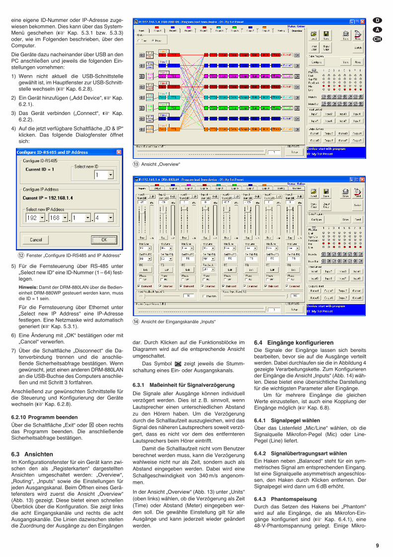
eine eigene ID-Nummer oder IP-Adresse zuge-wiesen bekommen. Dies kann über das System-Menü geschehen (� Kap. 5.3.1 bzw. 5.3.3)oder, wie im Folgenden beschrieben, über denComputer.
Die Geräte dazu nacheinander über USB an denPC anschließen und jeweils die folgenden Ein-stellungen vornehmen:
1) Wenn nicht aktuell die USB-Schnittstellegewählt ist, im Hauptfenster zur USB-Schnitt-stelle wechseln (� Kap. 6.2.8).
2) Ein Gerät hinzufügen („Add Device“, � Kap.6.2.1).
3) Das Gerät verbinden („Connect“, � Kap.6.2.2).
4) Auf die jetzt verfügbare Schaltfläche „ID & IP“klicken. Das folgende Dialogfenster öffnetsich:
5) Für die Fernsteuerung über RS-485 unter„Select new ID“ eine ID-Nummer (1 – 64) fest-legen.
Hinweis: Damit der DRM-880LAN über die Bedien-einheit DRM-880WP gesteuert werden kann, mussdie ID = 1 sein.
Für die Fernsteuerung über Ethernet unter„Select new IP Address“ eine IP-Adressefestlegen. Eine Netzmaske wird automatischgeneriert (� Kap. 5.3.1).
6) Eine Änderung mit „OK“ bestätigen oder mit„Cancel“ verwerfen.
7) Über die Schaltfläche „Disconnect“ die Da -tenverbindung trennen und die an schlie-ßende Sicherheitsabfrage bestätigen. Wenngewünscht, jetzt einen anderen DRM-880LANan die USB-Buchse des Computers anschlie-ßen und mit Schritt 3 fortfahren.
Anschließend zur gewünschten Schnittstelle fürdie Steuerung und Konfigurierung der Gerätewechseln (� Kap. 6.2.8).
6.2.10 Programm beendenÜber die Schaltfläche „Exit“ oder ⊠ oben rechtsdas Programm beenden. Die an schließendeSicherheitsabfrage bestätigen.
6.3 AnsichtenIm Konfigurationsfenster für ein Gerät kann zwi-schen den als „Registerkarten“ dargestelltenAnsichten umgeschaltet werden: „Overview“,„Routing“, „Inputs“ sowie die Einstellungen fürjeden Ausgangskanal. Beim Öffnen eines Gerä-tefensters wird zuerst die Ansicht „Overview“(Abb. 13) gezeigt. Diese bietet einen schnellenÜberblick über die Konfiguration. Sie zeigt linksdie acht Eingangskanäle und rechts die achtAusgangskanäle. Die Linien dazwischen stellendie Zuordnung der Ausgänge zu den Eingängen
⑫ Fenster „Configure ID-RS485 and IP Address“
D
A
CH
9
⑭ Ansicht der Eingangskanäle „Inputs“
⑬ Ansicht „Overview“
dar. Durch Klicken auf die Funktionsblöcke imDiagramm wird auf die entsprechende Ansichtumgeschaltet.
Das Symbol zeigt jeweils die Stumm-schaltung eines Ein- oder Ausgangskanals.
6.3.1 Maßeinheit für Signalverzögerung
Die Signale aller Ausgänge können individuellverzögert werden. Dies ist z. B. sinnvoll, wennLautsprecher einen unterschiedlichen Abstandzu den Hörern haben. Um die Verzögerungdurch die Schalllaufzeit auszugleichen, wird dasSignal des näheren Lautsprechers soweit verzö-gert, dass es nicht vor dem des entfernterenLautsprechers beim Hörer eintrifft.
Damit die Schalllaufzeit nicht vom Benutzerberechnet werden muss, kann die Verzögerungwahlweise nicht nur als Zeit, sondern auch alsAbstand eingegeben werden. Dabei wird eineSchallgeschwindigkeit von 340 m/s angenom-men.
In der Ansicht „Overview“ (Abb. 13) unter „Units“(oben links) wählen, ob die Verzögerung als Zeit(Time) oder Abstand (Meter) eingegeben wer-den soll. Die gewählte Einstellung gilt für alleAusgänge und kann jederzeit wieder geändertwerden.
6.4 Eingänge konfigurierenDie Signale der Eingänge lassen sich bereitsbearbeiten, bevor sie auf die Ausgänge verteiltwerden. Dabei durchlaufen sie die in Abbildung 4gezeigte Verarbeitungskette. Zum Konfigurierender Eingänge die Ansicht „Inputs“ (Abb. 14) wäh-len. Diese bietet eine übersichtliche Darstellungfür die wichtigsten Parameter aller Eingänge.
Um für mehrere Eingänge die gleichenWerte einzustellen, ist auch eine Kopplung derEingänge möglich (� Kap. 6.8).
6.4.1 Signalpegel wählenÜber das Listenfeld „Mic/ Line“ wählen, ob dieSignalquelle Mikrofon-Pegel (Mic) oder Line-Pegel (Line) liefert.
6.4.2 Signalübertragungsart wählenEin Haken neben „Balanced“ steht für ein sym-metrisches Signal am entsprechenden Eingang.Ist eine Signalquelle asymmetrisch angeschlos-sen, den Haken durch Klicken entfernen. DerSignalpegel wird dann um 6 dB erhöht.
6.4.3 PhantomspeisungDurch das Setzen des Hakens bei „Phantom“wird auf alle Eingänge, die als Mikrofon-Ein-gänge konfiguriert sind (� Kap. 6.4.1), eine48-V-Phantomspannung gelegt. Einige Mikro-
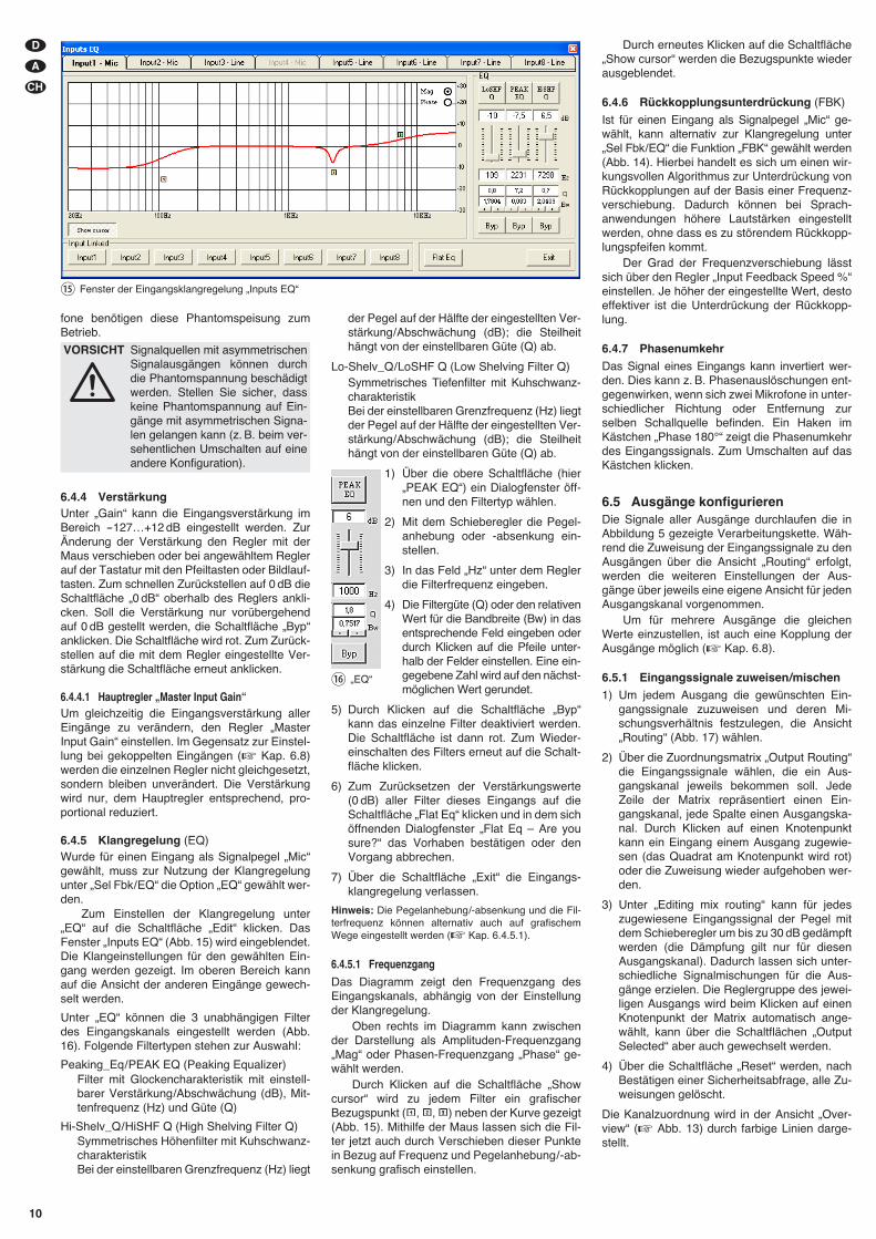
Durch erneutes Klicken auf die Schaltfläche„Show cursor“ werden die Bezugspunkte wiederausgeblendet.
6.4.6 Rückkopplungsunterdrückung (FBK)
Ist für einen Eingang als Signalpegel „Mic“ ge -wählt, kann alternativ zur Klangregelung unter„Sel Fbk/ EQ“ die Funktion „FBK“ gewählt werden(Abb. 14). Hierbei handelt es sich um einen wir-kungsvollen Algorithmus zur Unterdrückung vonRückkopplungen auf der Basis einer Frequenz-verschiebung. Dadurch können bei Sprach -anwendungen höhere Lautstärken eingestelltwerden, ohne dass es zu störendem Rückkopp-lungspfeifen kommt.
Der Grad der Frequenzverschiebung lässtsich über den Regler „Input Feedback Speed %“einstellen. Je höher der eingestellte Wert, destoeffektiver ist die Unterdrückung der Rückkopp-lung.
6.4.7 PhasenumkehrDas Signal eines Eingangs kann invertiert wer-den. Dies kann z. B. Phasenauslöschungen ent-gegenwirken, wenn sich zwei Mikrofone in unter-schiedlicher Richtung oder Entfernung zurselben Schallquelle befinden. Ein Haken imKästchen „Phase 180°“ zeigt die Phasenumkehrdes Eingangssignals. Zum Um schalten auf dasKästchen klicken.
6.5 Ausgänge konfigurierenDie Signale aller Ausgänge durchlaufen die inAbbildung 5 gezeigte Verarbeitungskette. Wäh-rend die Zuweisung der Eingangssignale zu denAusgängen über die Ansicht „Routing“ erfolgt,werden die weiteren Einstellungen der Aus-gänge über jeweils eine eigene Ansicht für jedenAusgangskanal vorgenommen.
Um für mehrere Ausgänge die gleichenWerte einzustellen, ist auch eine Kopplung derAusgänge möglich (� Kap. 6.8).
6.5.1 Eingangssignale zuweisen/mischen1) Um jedem Ausgang die gewünschten Ein-
gangssignale zuzuweisen und deren Mi -schungsverhältnis festzulegen, die Ansicht„Routing“ (Abb. 17) wählen.
2) Über die Zuordnungsmatrix „Output Routing“die Eingangssignale wählen, die ein Aus-gangskanal jeweils bekommen soll. JedeZeile der Matrix repräsentiert einen Ein-gangskanal, jede Spalte einen Ausgangska-nal. Durch Klicken auf einen Knotenpunktkann ein Eingang einem Ausgang zugewie-sen (das Quadrat am Knotenpunkt wird rot)oder die Zuweisung wieder aufgehoben wer-den.
3) Unter „Editing mix routing“ kann für jedeszugewiesene Eingangssignal der Pegel mitdem Schieberegler um bis zu 30 dB gedämpftwerden (die Dämpfung gilt nur für diesenAusgangskanal). Dadurch lassen sich unter-schiedliche Signalmischungen für die Aus-gänge erzielen. Die Reglergruppe des jewei-ligen Ausgangs wird beim Klicken auf einenKnotenpunkt der Matrix automatisch ange-wählt, kann über die Schaltflächen „OutputSelected“ aber auch gewechselt werden.
4) Über die Schaltfläche „Reset“ werden, nachBestätigen einer Sicherheitsabfrage, alle Zu -weisungen gelöscht.
Die Kanalzuordnung wird in der Ansicht „Over-view“ (� Abb. 13) durch farbige Linien darge-stellt.
D
A
CH
10
⑮ Fenster der Eingangsklangregelung „Inputs EQ“
fone benötigen diese Phantomspeisung zumBetrieb.
6.4.4 VerstärkungUnter „Gain“ kann die Eingangsverstärkung imBereich -127…+12 dB eingestellt werden. ZurÄnderung der Verstärkung den Regler mit derMaus verschieben oder bei angewähltem Reglerauf der Tastatur mit den Pfeiltasten oder Bildlauf-tasten. Zum schnellen Zurückstellen auf 0 dB dieSchaltfläche „0 dB“ oberhalb des Reglers ankli-cken. Soll die Verstärkung nur vorübergehendauf 0 dB gestellt werden, die Schaltfläche „Byp“anklicken. Die Schaltfläche wird rot. Zum Zurück-stellen auf die mit dem Regler eingestellte Ver-stärkung die Schaltfläche erneut anklicken.
6.4.4.1 Hauptregler „Master Input Gain“Um gleichzeitig die Eingangsverstärkung allerEingänge zu verändern, den Regler „MasterInput Gain“ einstellen. Im Gegensatz zur Einstel-lung bei gekoppelten Eingängen (� Kap. 6.8)werden die einzelnen Regler nicht gleichgesetzt,sondern bleiben unverändert. Die Verstärkungwird nur, dem Hauptregler entsprechend, pro-portional reduziert.
6.4.5 Klangregelung (EQ)Wurde für einen Eingang als Signalpegel „Mic“gewählt, muss zur Nutzung der Klangregelungunter „Sel Fbk/ EQ“ die Option „EQ“ gewählt wer-den.
Zum Einstellen der Klangregelung unter„EQ“ auf die Schaltfläche „Edit“ klicken. DasFenster „Inputs EQ“ (Abb. 15) wird eingeblendet.Die Klangeinstellungen für den gewählten Ein-gang werden gezeigt. Im oberen Bereich kannauf die Ansicht der anderen Eingänge gewech-selt werden.
Unter „EQ“ können die 3 unabhängigen Filterdes Eingangskanals eingestellt werden (Abb.16). Folgende Filtertypen stehen zur Auswahl:
Peaking_Eq/ PEAK EQ (Peaking Equalizer)Filter mit Glockencharakteristik mit einstell-barer Verstärkung/Abschwächung (dB), Mit-tenfrequenz (Hz) und Güte (Q)
Hi-Shelv_Q/ HiSHF Q (High Shelving Filter Q)Symmetrisches Höhenfilter mit Kuhschwanz -charakteristikBei der einstellbaren Grenz frequenz (Hz) liegt
der Pegel auf der Hälfte der eingestellten Ver-stärkung/ Ab schwächung (dB); die Steilheithängt von der einstellbaren Güte (Q) ab.
Lo-Shelv_Q/ LoSHF Q (Low Shelving Filter Q)Symmetrisches Tiefenfilter mit Kuhschwanz -charakteristikBei der einstellbaren Grenz frequenz (Hz) liegtder Pegel auf der Hälfte der eingestellten Ver-stärkung/ Ab schwächung (dB); die Steilheithängt von der einstellbaren Güte (Q) ab.
1) Über die obere Schaltfläche (hier„PEAK EQ“) ein Dialogfenster öff-nen und den Filtertyp wählen.
2) Mit dem Schieberegler die Pegel-anhebung oder -absenkung ein-stellen.
3) In das Feld „Hz“ unter dem Reglerdie Filterfrequenz eingeben.
4) Die Filtergüte (Q) oder den relativenWert für die Bandbreite (Bw) in dasentsprechende Feld eingeben oderdurch Klicken auf die Pfeile unter-halb der Felder einstellen. Eine ein-gegebene Zahl wird auf den nächst-möglichen Wert gerundet.
5) Durch Klicken auf die Schaltfläche „Byp“kann das einzelne Filter deaktiviert werden.Die Schaltfläche ist dann rot. Zum Wieder-einschalten des Filters erneut auf die Schalt-fläche klicken.
6) Zum Zurücksetzen der Verstärkungswerte(0 dB) aller Filter dieses Eingangs auf dieSchaltfläche „Flat Eq“ klicken und in dem sichöffnenden Dialogfenster „Flat Eq – Are yousure?“ das Vorhaben bestätigen oder denVorgang abbrechen.
7) Über die Schaltfläche „Exit“ die Eingangs-klangregelung verlassen.
Hinweis: Die Pegelanhebung/-absenkung und die Fil-terfrequenz können alternativ auch auf grafischemWege eingestellt werden (� Kap. 6.4.5.1).
6.4.5.1 Frequenzgang
Das Diagramm zeigt den Frequenzgang desEingangskanals, abhängig von der Einstellungder Klangregelung.
Oben rechts im Diagramm kann zwischender Darstellung als Amplituden-Frequenzgang„Mag“ oder Phasen-Frequenzgang „Phase“ ge -wählt werden.
Durch Klicken auf die Schaltfläche „Showcursor“ wird zu jedem Filter ein grafischerBezugspunkt ( , , ) neben der Kurve gezeigt(Abb. 15). Mithilfe der Maus lassen sich die Fil-ter jetzt auch durch Verschieben dieser Punktein Bezug auf Frequenz und Pegelanhebung/ -ab -senkung grafisch einstellen.
⑯ „EQ“
VORSICHT Signalquellen mit asymmetrischenSignalausgängen können durchdie Phantomspannung beschädigtwerden. Stellen Sie sicher, dasskeine Phantomspannung auf Ein-gänge mit asymmetrischen Signa-len gelangen kann (z. B. beim ver-sehentlichen Umschalten auf eineandere Konfiguration).
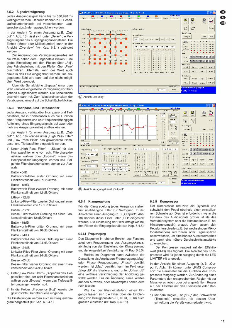
6.5.2 SignalverzögerungJedes Ausgangssignal kann bis zu 380,998 msverzögert werden. Dadurch können z. B. Schall-laufzeitunterschiede bei verschiedenen Laut-sprecherabständen ausgeglichen werden.
In der Ansicht für einen Ausgang (z. B. „Out-put1“, Abb. 18) lässt sich unter „Delay“ die Ver-zögerung für das Ausgangssignal einstellen. DieEinheit (Meter oder Millisekunden) kann in derAnsicht „Overview“ (� Kap. 6.3.1) geändertwerden.
Zur Änderung des Verzögerungswertes aufdie Pfeile neben dem Eingabefeld klicken: Einegrobe Einstellung mit den Pfeilen über „Adj“,eine Feineinstellung mit den Pfeilen über „Fine“durchführen. Alternativ kann der Wert auchdirekt in das Feld eingegeben werden. Die ein-gegebene Zahl wird dann auf den nächstmögli-chen Wert gerundet.
Über die Schaltfläche „Bypass“ unter demWert kann die eingestellte Verzögerung vorüber-gehend ausgeschaltet werden. Die Schaltflächeerscheint dann rot. Zum Wiedereinschalten derVerzögerung erneut auf die Schaltfläche klicken.
6.5.3 Hochpass- und TiefpassfilterJeder Ausgang verfügt über Hochpass- und Tief-passfilter, die in Kombination auch die Funktioneiner Frequenzweiche (zur frequenzabhängigenAufteilung eines Eingangssignals auf zwei odermehrere Ausgangskanäle) erfüllen können.
In der Ansicht für einen Ausgang (z. B. „Out-put1“, Abb. 18) können unter „High Pass Filter“und „Low Pass Filter“ das gewünschte Hoch-pass- und Tiefpassfilter eingestellt werden.
1) Unter „High Pass Filter“ – „Slope“ für dasHochpassfilter eine von acht Filtercharakte-ristiken wählen oder „Bypass“, wenn dasHochpassfilter umgangen werden soll. Fol-gende Filtercharakteristiken stehen zur Aus-wahl:
Buttw -6dBButterworth-Filter erster Ordnung mit einerFlankensteilheit von 6 dB/ Oktave
Buttw -12dBButterworth-Filter zweiter Ordnung mit einerFlankensteilheit von 12 dB/ Oktave
LRiley -12dBLinkwitz-Riley-Filter zweiter Ordnung mit einerFlankensteilheit von 12 dB/ Oktave
Bessel -12dBBessel-Filter zweiter Ordnung mit einer Flan-kensteilheit von 12 dB/ Oktave
Buttw -18dBButterworth-Filter dritter Ordnung mit einerFlankensteilheit von 18 dB/ Oktave
Buttw -24dBButterworth-Filter vierter Ordnung mit einerFlankensteilheit von 24 dB/ Oktave
LRiley -24dBLinkwitz-Riley-Filter vierter Ordnung mit einerFlankensteilheit von 24 dB/ Oktave
Bessel -24dBBessel-Filter vierter Ordnung mit einer Flan-kensteilheit von 24 dB/ Oktave
2) Unter „Low Pass Filter“ – „Slope“ für das Tief-passfilter eine der acht Filtercharakteristikenwählen oder „Bypass“, wenn das Tiefpassfil-ter umgangen werden soll.
3) In die Felder „Frequency [Hz]“ jeweils diegewünschte Grenzfrequenz eingeben.
Die Einstellungen werden auch im Frequenzdia-gram dargestellt (� Kap. 6.5.4.1).
D
A
CH
11
⑰ Ansicht „Routing“
⑱ Ansicht Ausgangskanal „Output1“
6.5.4 Klangregelung
Für die Klangregelung jedes Ausgangs stehenfünf unabhängige Filter zur Verfügung. In derAnsicht für einen Ausgang (z. B. „Output1“, Abb.18) können diese Filter unter „EQ“ eingestelltwerden. Die Einstellung der Filter erfolgt wie beiden Filtern der Eingangskanäle (� Kap. 6.4.5).
6.5.4.1 Frequenzgang
Das Diagramm im oberen Bereich des Fensterszeigt den Frequenzgang des Ausgangskanals,abhängig von der Einstellung der Klangregelungund der eingestellten Verstärkung (�Kap. 6.5.6).
Rechts im Diagramm kann zwischen derDarstellung als Amplituden-Frequenzgang „Mag“oder Phasen-Frequenzgang „Phase“ ge wähltwerden. Ist „Mag“ gewählt, kann im Feld unter„Step dB“ die Skalierung und unter „Offset dB“eine vertikale Verschiebung der Abbildung ge -wählt werden. Für die Änderung eines Wertesauf den Aufwärts- oder Abwärtspfeil neben demFeld klicken.
Wie bei der Klangeinstellung eines Ein-gangs lassen sich die Filter über die Einblen-dung von Bezugspunkten ( , , , , ) auchgrafisch einstellen (� Kap. 6.4.5.1).
6.5.5 KompressorDer Kompressor reduziert die Dynamik undschwächt den Pegel oberhalb einer einstellba-ren Schwelle ab. Dies ist erforderlich, wenn dieDynamik des Audiosignals größer ist als dasVerstärkersystem oder die Hörsituation (z. B. beiHintergrundmusik) erlaubt. Auch lassen sichPegelunterschiede (z. B. bei wechselnden Mikro-fonabständen) reduzieren oder Signalspitzenabschwächen, um eine höhere Aussteuerbarkeitund damit eine höhere Durchschnittslautstärkezu erreichen.
Der Kompressor reagiert auf den Effektiv-wert (RMS) des Signals. Die Aktivität des Kom-pressors wird für jeden Ausgang durch die LEDLIMITER (4) angezeigt.
In der Ansicht für einen Ausgang (z. B. „Out-put1“, Abb. 18) können unter „RMS Compres-sor“ die Parameter für die Funktion des Kom-pressors festgelegt werden. Zur Änderung einesParameters den entsprechenden Regler mit derMaus verschieben oder bei angewähltem Reglerauf der Tastatur mit den Pfeiltasten oder Bild-lauftasten.
1) Mit dem Regler „Thr [dBu]“ den Schwellwert(Threshold) einstellen, ab dessen Über-schreitung die Verstärkung reduziert wird.
2) Mit dem Regler „Ratio“ das Kompressions-verhältnis einstellen. Dabei bedeutet z. B. einKompressionsverhältnis von 10 : 1, dass sichoberhalb des Schwellwertes bei einem Ein-gangspegelanstieg von 20 dB der Ausgangs-pegel nur um 2 dB erhöht.
3) Mit dem Regler „Attack [ms]“ die Ansprech-zeit (Attack Time) einstellen.
4) Mit dem Regler „Release [sec.]“ die Rückstell-zeit (Release Time) einstellen, d. h. die Dauer,bis die Verstärkung wieder ihren ursprüngli-chen Wert erreicht, nachdem der Signalpegelden Schwellwert unterschritten hat.
5) Mit dem Regler „S/ H Knee [%]“ kann einge-stellt werden, ob beim Überschreiten desSchwellwertes der Wechsel zur Kompressionabrupt (0 % = Hard Knee) oder mit einemÜbergangsbereich (100 % = Soft Knee) erfol-gen soll. Der Wert bestimmt die Größe desÜbergangsbereichs.
6) Zum Umgehen des Kompressors oder zumWiedereinschalten auf die Schaltfläche „By -pass“ klicken. Bei ausgeschaltetem Kom-pressor ist die Schaltfläche rot.
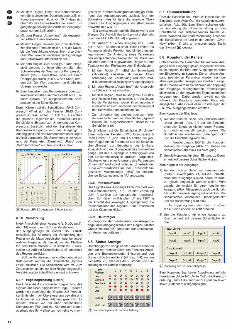
Durch Klicken auf die Schaltfläche „RMS Com-pressor“ öffnet sich das Fenster „RMS Com-pressor & Peak Limiter ...“ (Abb. 19). Es enthältdie gleichen Regler für die Parameter und dieSchaltfläche „Bypass“ zur Umgehung des Kom-pressors. Zusätzlich wird der Signalpegel desKompressor-Eingangs und des Ausgangs inAbhängigkeit von den Kompressoreinstellungengrafisch dargestellt. Die Auswirkung einer Ände-rung der Parameter „Threshold“, „Ratio“ oder„Soft/ Hard Knee“ wird hier sofort sichtbar.
6.5.6 Verstärkung
In der Ansicht für einen Ausgang (z. B. „Output1“,Abb. 18) unter „Lev [dB]“ die Verstärkung, d. h.den Ausgangspegel im Bereich -127…+18 dBeinstellen. Zur Änderung der Verstärkung denRegler mit der Maus verschieben oder bei ange-wähltem Regler auf der Tastatur mit den Pfeiltas-ten oder Bildlauftasten. Zum schnellen Zurück-stellen auf 0 dB die Schaltfläche „0 dB“ unterhalbdes Reglers anklicken.
Soll die Verstärkung nur vorübergehend auf0 dB gestellt werden, die Schaltfläche „BypassLevel“ anklicken. Die Schaltfläche wird rot. ZumZurückstellen auf die mit dem Regler eingestellteVerstärkung die Schaltfläche erneut anklicken.
6.5.7 Pegelbegrenzung (Limiter)Der Limiter dient zur schnellen Begrenzung desSignals auf einen eingestellten Pegel. Dadurchwerden die nachfolgenden Geräte (z. B. Verstär-ker-Endstufen) vor Übersteuerung be wahrt undLautsprecher vor Beschädigung geschützt. Erarbeitet ähnlich wie der oben beschriebeneKompressor. Während der Kompressor jedochoberhalb des Schwellwertes noch eine vom ein-
gestellten Kompressionsgrad abhängige Erhö-hung des Ausgangspegels zulässt, legt derSchwellwert des Limiters die absolute Ober-grenze des Ausgangssignals fest (Kompressi-onsverhältnis = ∞ : 1).
Der Limiter reagiert auf die Spitzenwerte desSignals. Die Aktivität des Limiters wird ebenfallsdurch die LED LIMITER (4) angezeigt.
In der Ansicht für einen Ausgang (z. B. „Out-put1“, Abb. 18) können unter „Peak Limiter“ dieParameter für die Funktion des Limiters festge-legt werden. Zur Änderung eines Parametersden entsprechenden Regler mit der Maus ver-schieben oder bei angewähltem Regler auf derTastatur mit den Pfeiltasten oder Bildlauftasten.
1) Mit dem Regler „Thr [dBu]“ den Schwellwert(Threshold) einstellen, ab dessen Über-schreitung die Verstärkung reduziert wird,d. h. den maximal zulässigen Ausgangspegel.
2) Mit dem Regler „Attack [ms]“ die Ansprech-zeit (Attack Time) einstellen.
3) Mit dem Regler „Release [sec.]“ die Rückstell-zeit (Release Time) einstellen, d. h. die Dauer,bis die Verstärkung wieder ihren ursprüngli-chen Wert erreicht, nachdem der Signalpegelden Schwellwert unterschritten hat.
4) Zum Umgehen des Limiters oder zum Wie-dereinschalten auf die Schaltfläche „Bypass“klicken. Bei ausgeschaltetem Limiter ist dieSchaltfläche rot.
Durch Klicken auf die Schaltfläche „P. Limiter“öffnet sich das Fenster „RMS Compressor &Peak Limiter ...“ (Abb. 19). Es enthält die glei-chen Regler für die Parameter und die Schaltflä-che „Bypass“ zur Umgehung des Limiters.Zusätzlich wird der Signalpegel des Limiter-Ein-gangs und des Ausgangs in Abhängigkeit vonden Limitereinstellungen grafisch dargestellt.Die Auswirkung einer Änderung des Parameters„Threshold“ wird sofort sichtbar. Unterhalb derKurve wird zusätzlich zum über „Threshold“ ein-gestellten Maximalpegel [dBu] die entspre-chende Spitzenspannung [Vp] angezeigt.
6.5.8 PhasenumkehrDas Signal eines Ausgangs kann invertiert wer-den (Phasenumkehr), z. B. um eine Verpolungbeim Anschluss der Lautsprecher auszuglei-chen. Ein Haken im Kästchen „Phase 180°“ inder Ansicht des jeweiligen Ausgangs zeigt diePhasenumkehr des Signals. Zum Um schaltenauf das Kästchen klicken.
6.5.9 HauptreglerZur proportionalen Veränderung der Ausgangs-pegel aller Ausgangskanäle den Regler „MasterOutput Volume [dB]“ unterhalb der umschaltba-ren Ansichten betätigen.
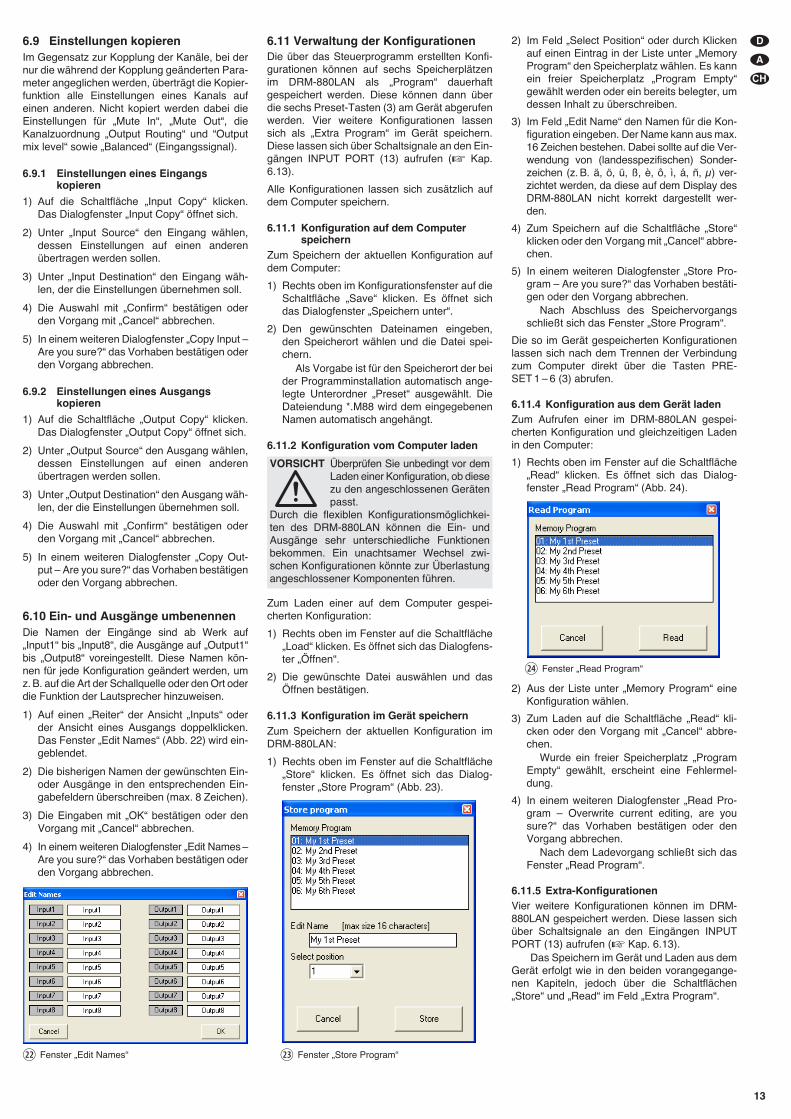
6.6 Status-AnzeigeUnabhängig von der gewählten Ansicht befindensich auf der rechten Seite des Fensters Anzei-gen und Bedienelemente. Entsprechend denStatus-LEDs (4) am Gerät (� Kap. 5.4), werdenhier (Abb. 20) ebenfalls die Zustände und Ein-stellungen der Kanäle angezeigt.
6.7 StummschaltungÜber die Schaltflächen „Mute In“ lassen sich dieEingänge, über „Mute Out“ die Ausgänge stumm-schalten (Abb. 20). Zum Stummschalten oderzur Aufhebung der Stummschaltung auf dieSchaltfläche des entsprechenden Kanals kli-cken. Während der Stummschaltung erscheintdie Schaltfläche rot und in der Ansicht „Over-view“ (Abb. 13) wird an entsprechender Stelledas Symbol gezeigt.
6.8 Kopplung der KanäleSollen bestimmte Parameter für mehrere Aus-gänge oder Eingänge gleich eingestellt werden,ist es möglich, die Ein- oder Ausgänge währendder Einstellung zu koppeln. Die an einem Aus-gang geänderten Parameter werden nun beiallen gekoppelten Ausgängen identisch einge-stellt. Ebenso werden die während der Kopplungder Eingänge durchgeführten Einstellungengleichzeitig an den gewählten Eingangskanälenvorgenommen. Dabei werden jeweils nur diewährend der Kopplung geänderten Parameterangeglichen. Alle individuellen Einstellungen derEin- bzw. Ausgänge bleiben erhalten.
Zum Koppeln der Eingänge:
1) Auf der rechten Seite des Fensters unter„Input Linked“ (Abb. 21) auf die Schaltflä-chen aller Eingänge klicken, deren Parame-ter gleich eingestellt werden sollen. DieSchaltflächen er scheinen „hineingedrückt“und die Be schriftung wird blau.
Im Fenster „Inputs EQ“ für die Klangein-stellung der Eingänge (Abb. 15) stehen dieSchaltflächen ebenfalls zur Verfügung.
2) Um die Kopplung für einen Eingang zu lösen,erneut auf dessen Schaltfläche klicken.
Zum Koppeln der Ausgänge:
1) Auf der rechten Seite des Fensters unter„Output Linked“ (Abb. 21) auf die Schaltflä-chen aller Ausgänge klicken, deren Parame-ter gleich eingestellt werden sollen. Wirdgerade die Ansicht für einen bestimmtenAusgang (Abb. 18) gezeigt, auch die Schalt-fläche für diesen Ausgang mit anklicken. DieSchaltflächen erscheinen „hineingedrückt“und die Be schriftung wird blau.
Die Kopplung bleibt auch beim Umschal-ten auf eine andere Ansicht erhalten.
2) Um die Kopplung für einen Ausgang zulösen, erneut auf dessen Schaltfläche kli-cken.
Eine Kopplung hat keine Auswirkung auf dieFunktionen „Mute In“, „Mute Out“, die Kanalzu-ordnung „Output Routing“ und “Output mix level“sowie „Balanced“ (Eingangssignal).
㉑ Kopplung der Ein- oder Ausgänge
⑳ Statusanzeigen und Stummschaltung
⑲ Fenster „RMS Compressor & Peak Limiter“
D
A
CH
12
6.9 Einstellungen kopierenIm Gegensatz zur Kopplung der Kanäle, bei dernur die während der Kopplung geänderten Para-meter angeglichen werden, überträgt die Kopier-funktion alle Einstellungen eines Kanals aufeinen anderen. Nicht kopiert werden dabei dieEinstellungen für „Mute In“, „Mute Out“, dieKanalzuordnung „Output Routing“ und “Outputmix level“ sowie „Balanced“ (Eingangssignal).
6.9.1 Einstellungen eines Eingangskopieren
1) Auf die Schaltfläche „Input Copy“ klicken.Das Dialogfenster „Input Copy“ öffnet sich.
2) Unter „Input Source“ den Eingang wählen,dessen Einstellungen auf einen anderenübertragen werden sollen.
3) Unter „Input Destination“ den Eingang wäh-len, der die Einstellungen übernehmen soll.
4) Die Auswahl mit „Confirm“ bestätigen oderden Vorgang mit „Cancel“ abbrechen.
5) In einem weiteren Dialogfenster „Copy Input –Are you sure?“ das Vorhaben bestätigen oderden Vorgang abbrechen.
6.9.2 Einstellungen eines Ausgangskopieren
1) Auf die Schaltfläche „Output Copy“ klicken.Das Dialogfenster „Output Copy“ öffnet sich.
2) Unter „Output Source“ den Ausgang wählen,dessen Einstellungen auf einen anderenübertragen werden sollen.
3) Unter „Output Destination“ den Ausgang wäh-len, der die Einstellungen übernehmen soll.
4) Die Auswahl mit „Confirm“ bestätigen oderden Vorgang mit „Cancel“ abbrechen.
5) In einem weiteren Dialogfenster „Copy Out-put – Are you sure?“ das Vorhaben bestätigenoder den Vorgang abbrechen.
6.10 Ein- und Ausgänge umbenennenDie Namen der Eingänge sind ab Werk auf„Input1“ bis „Input8“, die Ausgänge auf „Output1“bis „Output8“ voreingestellt. Diese Namen kön-nen für jede Konfiguration geändert werden, umz. B. auf die Art der Schallquelle oder den Ort oderdie Funktion der Lautsprecher hinzuweisen.
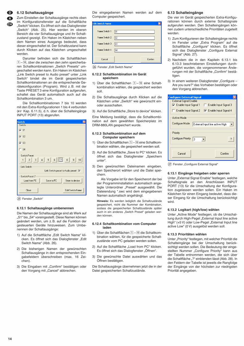
1) Auf einen „Reiter“ der Ansicht „Inputs“ oderder Ansicht eines Ausgangs doppelklicken.Das Fenster „Edit Names“ (Abb. 22) wird ein-geblendet.
2) Die bisherigen Namen der gewünschten Ein-oder Ausgänge in den entsprechenden Ein-gabefeldern überschreiben (max. 8 Zeichen).
3) Die Eingaben mit „OK“ bestätigen oder denVorgang mit „Cancel“ abbrechen.
4) In einem weiteren Dialogfenster „Edit Names –Are you sure?“ das Vorhaben bestätigen oderden Vorgang abbrechen.
6.11 Verwaltung der KonfigurationenDie über das Steuerprogramm erstellten Konfi-gurationen können auf sechs Speicherplätzenim DRM-880LAN als „Program“ dauerhaftgespeichert werden. Diese können dann überdie sechs Preset-Tasten (3) am Gerät abgerufenwerden. Vier weitere Konfigurationen lassensich als „Extra Program“ im Gerät speichern.Diese lassen sich über Schaltsignale an den Ein-gängen INPUT PORT (13) aufrufen (� Kap.6.13).
Alle Konfigurationen lassen sich zusätzlich aufdem Computer speichern.
6.11.1 Konfiguration auf dem Computerspeichern
Zum Speichern der aktuellen Konfiguration aufdem Computer:
1) Rechts oben im Konfigurationsfenster auf dieSchaltfläche „Save“ klicken. Es öffnet sichdas Dialogfenster „Speichern unter“.
2) Den gewünschten Dateinamen eingeben,den Speicherort wählen und die Datei spei-chern.
Als Vorgabe ist für den Speicherort der beider Programminstallation automatisch ange-legte Unterordner „Preset“ ausgewählt. DieDateiendung *.M88 wird dem eingegebenenNamen automatisch angehängt.
6.11.2 Konfiguration vom Computer laden
Zum Laden einer auf dem Computer gespei-cherten Konfiguration:
1) Rechts oben im Fenster auf die Schaltfläche„Load“ klicken. Es öffnet sich das Dialogfens-ter „Öffnen“.
2) Die gewünschte Datei auswählen und dasÖffnen bestätigen.
6.11.3 Konfiguration im Gerät speichernZum Speichern der aktuellen Konfiguration imDRM-880LAN:
1) Rechts oben im Fenster auf die Schaltfläche„Store“ klicken. Es öffnet sich das Dialog-fenster „Store Program“ (Abb. 23).
2) Im Feld „Select Position“ oder durch Klickenauf einen Eintrag in der Liste unter „MemoryProgram“ den Speicherplatz wählen. Es kannein freier Speicherplatz „Program Empty“gewählt werden oder ein bereits belegter, umdessen Inhalt zu überschreiben.
3) Im Feld „Edit Name“ den Namen für die Kon-figuration eingeben. Der Name kann aus max.16 Zeichen bestehen. Dabei sollte auf die Ver-wendung von (landesspezifischen) Sonder-zeichen (z. B. ä, ö, ü, ß, è, ô, ì, á, ñ, μ) ver-zichtet werden, da diese auf dem Display desDRM-880LAN nicht korrekt dargestellt wer-den.
4) Zum Speichern auf die Schaltfläche „Store“klicken oder den Vorgang mit „Cancel“ abbre-chen.
5) In einem weiteren Dialogfenster „Store Pro-gram – Are you sure?“ das Vorhaben bestäti-gen oder den Vorgang abbrechen.
Nach Abschluss des Speichervorgangsschließt sich das Fenster „Store Program“.
Die so im Gerät gespeicherten Konfigurationenlassen sich nach dem Trennen der Verbindungzum Computer direkt über die Tasten PRE-SET 1 – 6 (3) abrufen.
6.11.4 Konfiguration aus dem Gerät ladenZum Aufrufen einer im DRM-880LAN gespei-cherten Konfiguration und gleichzeitigen Ladenin den Computer:
1) Rechts oben im Fenster auf die Schaltfläche„Read“ klicken. Es öffnet sich das Dialog-fenster „Read Program“ (Abb. 24).
2) Aus der Liste unter „Memory Program“ eineKonfiguration wählen.
3) Zum Laden auf die Schaltfläche „Read“ kli-cken oder den Vorgang mit „Cancel“ abbre-chen.
Wurde ein freier Speicherplatz „ProgramEmpty“ gewählt, erscheint eine Fehlermel-dung.
4) In einem weiteren Dialogfenster „Read Pro-gram – Overwrite current editing, are yousure?“ das Vorhaben bestätigen oder denVorgang abbrechen.
Nach dem Ladevorgang schließt sich dasFenster „Read Program“.
6.11.5 Extra-KonfigurationenVier weitere Konfigurationen können im DRM-880LAN gespeichert werden. Diese lassen sichüber Schaltsignale an den Eingängen INPUTPORT (13) aufrufen (� Kap. 6.13).
Das Speichern im Gerät und Laden aus demGerät erfolgt wie in den beiden vorangegange-nen Kapiteln, jedoch über die Schaltflächen„Store“ und „Read“ im Feld „Extra Program“.
㉔ Fenster „Read Program“
㉓ Fenster „Store Program“
VORSICHT Überprüfen Sie unbedingt vor demLaden einer Konfiguration, ob diesezu den angeschlossenen Gerätenpasst.
Durch die flexiblen Konfigurationsmöglichkei-ten des DRM-880LAN können die Ein- undAusgänge sehr unterschiedliche Funktionenbekommen. Ein unachtsamer Wechsel zwi-schen Konfigurationen könnte zur Überlastungangeschlossener Komponenten führen.
㉒ Fenster „Edit Names“
D
A
CH
13
6.12 SchaltausgängeZum Einstellen der Schaltausgänge rechts obenim Konfigurationsfenster auf die Schaltfläche„Switch“ klicken. Es öffnet sich das Dialogfenster„Switch“ (Abb. 25). Hier werden im oberenBereich die vier Schaltausgänge und ihr Schalt-zustand gezeigt. Ein Haken im Kästchen nebendem Namen eines Ausgangs bedeutet, dassdieser eingeschaltet ist. Der Schaltzustand kanndurch Klicken auf das Kästchen umgeschaltetwerden.
Darunter befinden sich die Schaltflächen1 – 10, über die zwischen den zehn speicherba-ren Schaltkombinationen „Switch Presets“ um -geschaltet werden kann. Ein Haken im Kästchen„Link Switch preset to Audio preset“ unter „LinkSwitch“ bindet die im Gerät gespeichertenSchaltkombinationen an die entsprechende Ge -rätekonfiguration (Program). Wird z. B. mit derTaste PRESET 3 eine Konfiguration aufgerufen,schaltet das Gerät automatisch auch auf dieSchaltkombination 3 um.
Die Schaltkombinationen 7 bis 10 werdenmit den Extra-Konfigurationen 1 bis 4 verbunden(� Kap. 6.11.5), d. h. über die SchalteingängeINPUT PORT (13) abgerufen.
6.12.1 Schaltausgänge umbenennen
Die Namen der Schaltausgänge sind ab Werk auf„S1“ bis „S4“ voreingestellt. Diese Namen könnengeändert werden, um z. B. auf die Funktion dergesteuerten Geräte hinzuweisen. Zum Umbe-nennen der Schaltausgänge:
1) Auf die Schaltfläche „Edit Switch Name“ kli-cken. Es öffnet sich das Dialogfenster „EditSwitch Name“ (Abb. 26).
2) Die bisherigen Namen der gewünschtenSchaltausgänge in den entsprechenden Ein-gabefeldern überschreiben (max. 16 Zei-chen).
3) Die Eingaben mit „Confirm“ bestätigen oderden Vorgang mit „Cancel“ abbrechen.
Die eingegebenen Namen werden auf demComputer gespeichert.
6.12.2 Schaltkombination im Gerätspeichern
1) Über die Schaltflächen 1 – 10 eine Schalt-kombination wählen, die gespeichert werdensoll.
2) Die Schaltausgänge durch Klicken auf dieKästchen unter „Switch“ wie gewünscht ein-oder ausschalten.
3) Auf die Schaltfläche „Store to device“ klicken.
Eine Meldung bestätigt, dass die Schaltkombi-nation auf dem gewählten Speicherplatz imDRM-880LAN gespeichert wurde.
6.12.3 Schaltkombination auf demComputer speichern
1) Über die Schaltflächen 1– 10 eine Schaltkom-bination wählen, die gespeichert werden soll.
2) Auf die Schaltfläche „Save to PC“ klicken. Esöffnet sich das Dialogfenster „Speichernunter“.
3) Den gewünschten Dateinamen eingeben,den Speicherort wählen und die Datei spei-chern.
Als Vorgabe ist für den Speicherort der beider Programminstallation automatisch ange-legte Unterordner „Preset“ ausgewählt. DieDateiendung *.swc wird dem eingegebenenNamen automatisch angehängt.
Hinweis: Es werden lediglich die Schaltzuständegespeichert, nicht die Nummer der Kombination,sodass die gespeicherten Schaltzustände späterauch in ein anderes „Switch Preset“ geladen wer-den können.
6.12.4 Schaltkombination vom Computerladen
1) Über die Schaltflächen 1– 10 die Schaltkom-bination wählen, für die gespeicherte Schalt-zustände vom PC geladen werden sollen.
2) Auf die Schaltfläche „Load from PC“ klicken.Es öffnet sich das Dialogfenster „Öffnen“.
3) Die gewünschte Datei auswählen und dasÖffnen bestätigen.
Die Schaltausgänge übernehmen jetzt die in derDatei gespeicherten Schaltzustände.
6.13 SchalteingängeDie vier im Gerät gespeicherten Extra-Konfigu-rationen können durch externe Schaltsignaleaufgerufen werden. Den Schalteingängen kön-nen zudem unterschiedliche Prioritäten zugeteiltwerden.
1) Zum Konfigurieren der Schalteingänge rechtsim Fenster unter „Extra Program“ auf dieSchaltfläche „Configure“ klicken. Es öffnetsich das Dialogfenster „Configure ExternalSignal“ (Abb. 27).
2) Nachdem die in den Kapiteln 6.13.1 bis6.13.3 beschriebenen Einstellungen durch-geführt wurden, die vorgenommenen Ände-rungen mit der Schaltfläche „Confirm“ bestä-tigen.
3) In einem weiteren Dialogfenster „Configure –Are you sure?“ das Vorhaben bestätigen oderden Vorgang abbrechen.
6.13.1 Eingänge freigeben oder sperrenUnter „External Signal Enable“ festlegen, welcheSchaltsignale an den Anschlüssen INPUTPORT (13) für die Umschaltung der Konfigura-tion zugelassen werden sollen. Ein Haken imKästchen für einen Eingang bedeutet, dass die-ser Eingang für die Umschaltung berücksichtigtwird.
6.13.2 Logikart (high/ low) wählenUnter „Active Mode“ festlegen, ob die Umschal-tung durch High-Pegel „External Input line activeHigh“ (+5 V) oder Low-Pegel „External Input lineactive Low“ (0 V) ausgelöst werden soll.
6.13.3 Prioritäten wählenUnter „Priority“ festlegen, mit welcher Priorität dieSchalteingänge bei der Umschaltung be rück-sichtigt werden sollen. Die Bedeutung der einge-stellten Nummer „Configure Priority“ kann ausder Tabelle entnommen werden, die sich überdie Schaltfläche „?“ einblenden lässt (Abb. 28). Inden Feldern der Tabelle ist jeweils die Rangfolgeder Eingänge von der höchsten zur niedrigstenPriorität angegeben.
㉗ Fenster „Configure External Signal“
㉖ Fenster „Edit Switch Name“
㉕ Fenster „Switch“
D
A
CH
14
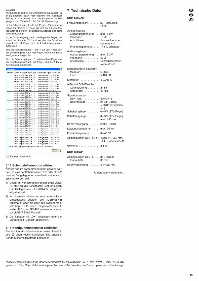
Beispiel:Alle Eingänge sind für die Umschaltung zugelassen. Esist als Logikart „active High“ gewählt und „ConfigurePriority“ = 3 eingestellt, d. h. die Rangfolge der Ein-gänge ist laut Tabelle S1, S4, S3, S2. Daraus folgt:
Ist der Schalteingang 1 auf High-Pegel (+5 V liegen zwi-schen der Klemme „S1“ und ) wird die 1. Extra-Kon-figuration aufgerufen (die anderen Eingänge sind damitohne Bedeutung).
Ist der Schalteingang 1 auf Low-Pegel (0 V liegen zwi-schen der Klemme „S1“ und ) aber der Schaltein-gang 4 auf High-Pegel, wird die 4. Extra-Konfigurationaufgerufen.
Sind die Schalteingänge 1 und 4 auf Low-Pegel aberder Schalteingang 3 auf High-Pegel, wird die 3. Extra-Konfiguration aufgerufen.
Sind die Schalteingänge 1, 3 und 4 auf Low-Pegel aberder Schalteingang 2 auf High-Pegel, wird die 2. Extra-Konfiguration aufgerufen.
6.14 Schnittstellenmodus wählenÄhnlich wie im Systemmenü kann gewählt wer-den, ob eine der Schnittstellen USB oder RS 485manuell festgelegt oder vom Gerät automatischerkannt werden soll.
1) Unten im Konfigurationsfenster unter „USB/RS 485“ auf die Schaltfläche „Setup“ klicken.Das Dialogfenster „USB/ RS 485 Setup“ wirdeingeblendet.
2) Im Listenfeld wählen, ob eine automatischeUmschaltung erfolgen soll „USB/ RS 485Automatic“ oder die über das System-Menü(� Kap. 5.3.2) zuletzt eingestellte Schnitt-stelle USB oder RS-485 verwendet werdensoll „USB/ RS 485 Manual“.
3) Die Eingabe mit „OK“ bestätigen oder denVorgang mit „Cancel“ abbrechen.
6.15 Konfigurationsfenster schließenEin Konfigurationsfenster über seine Schaltflä-che ⊠ oben rechts schließen. Die an schlie-ßende Sicherheitsabfrage bestätigen.
7 Technische Daten
DRM-880LAN
Frequenzbereich: . . . . . . . 20 – 20 000 Hz±1 dB
AudioeingängeEingangsspannung: . . . max. 6,2 VImpedanz: . . . . . . . . . . . 10 kΩAnschlüsse: . . . . . . . . . . Schraubklemmen,
symmetrischPhantomspannung: . . . . +48 V, schaltbar
AudioausgängeAusgangsspannung: . . . max. 6,2 VImpedanz: . . . . . . . . . . . 50 ΩAnschlüsse: . . . . . . . . . . Schraubklemmen,
symmetrisch
Störabstand (A-bewertet)Mikrofon: . . . . . . . . . . . . > 98 dBLine: . . . . . . . . . . . . . . . > 104 dB
Klirrfaktor: . . . . . . . . . . . . . < 0,005 %
A / D- und D /A-WandlerQuantisierung: . . . . . . . . 24 BitAbtastrate: . . . . . . . . . . . 48 kHz
SignalprozessorDSP-Typ: . . . . . . . . . . . SAM3716Datenformat: . . . . . . . . . 24 Bit (Daten)
× 96 Bit (Koeffizien-ten)
Schalteingänge: . . . . . . . . 0 – 5 V (TTL-Pegel)
Schaltausgänge: . . . . . . . . 0 – 5 V (TTL-Pegel),max. 150 mA
Stromversorgung: . . . . . . . 230 V~ / 50 Hz
Leistungsaufnahme: . . . . . max. 20 VA
Einsatztemperatur: . . . . . . 0 – 40 °C
Abmessungen (B × H × T): 482 × 44 × 250 mm,1 HE (Höheneinheit)
Gewicht: . . . . . . . . . . . . . . 2,5 kg
DRM-880WP
Abmessungen (B × H): . . . 86 × 86 mmEinbautiefe: . . . . . . . . . . 30 mm
Stromversorgung: . . . . . . . 5 V�/ 20 mA
Änderungen vorbehalten.
㉘ Fenster „Priority info“
D
A
CH
15
Diese Bedienungsanleitung ist urheberrechtlich für MONACOR ® INTERNATIONAL GmbH & Co. KGgeschützt. Eine Reproduktion für eigene kommerzielle Zwecke – auch auszugsweise – ist untersagt.
16
GB Contents
1 Operating Elements and Connections 16
1.1 Front panel . . . . . . . . . . . . . . . . . . . . . 16
1.2 Rear panel . . . . . . . . . . . . . . . . . . . . . . 16
1.3 Control panel DRM-880WP . . . . . . . . . 17
2 Safety Notes . . . . . . . . . . . . . . . . . . . 17
3 Applications . . . . . . . . . . . . . . . . . . . . 17
4 Setting up and Connecting the Unit 17
4.1 Signal sources . . . . . . . . . . . . . . . . . . . 17
4.2 Amplifiers or other units . . . . . . . . . . . 17
4.3 External switching signals . . . . . . . . . . 17
4.4 Units to be controlled . . . . . . . . . . . . . 17
4.5 Control panel DRM-880WP . . . . . . . . . 17
4.6 Computer . . . . . . . . . . . . . . . . . . . . . . 17
4.7 Mains connection . . . . . . . . . . . . . . . . 18
5 Operation . . . . . . . . . . . . . . . . . . . . . . 18
5.1 Switching on/off . . . . . . . . . . . . . . . . . . 18
5.2 Selecting a configuration . . . . . . . . . . . 18
5.3 System settings . . . . . . . . . . . . . . . . . . 18
5.3.1 Setting the IP address . . . . . . . . . . . . . 18
5.3.2 Selecting an interface . . . . . . . . . . . . . 18
5.3.3 Unit number for RS-485 . . . . . . . . . . . 18
5.3.4 Retrieving switching combinations . . . 18
5.3.5 Linking switching combinations to configurations . . . . . . . . . . . . . . . . . 19
5.4 Status LEDs . . . . . . . . . . . . . . . . . . . . 19
5.5 Operation via DRM-880WP . . . . . . . . . 19
5.5.1 Setting up the control panel . . . . . . . . 19
6 Remote Control via a Computer . . . 19
6.1 Installing PC software . . . . . . . . . . . . . 19
6.1.1 Installing an interface driver . . . . . . . . 19
6.2 Starting the PC software . . . . . . . . . . . 19
6.2.1 Adding units . . . . . . . . . . . . . . . . . . . . 19
6.2.2 Connecting or disconnecting units . . . 20
6.2.3 Naming a unit . . . . . . . . . . . . . . . . . . . 20
6.2.4 Calling up the configuration window . . 20
6.2.5 Removing units . . . . . . . . . . . . . . . . . . 20
6.2.6 Saving a unit constellation . . . . . . . . . 20
6.2.7 Loading a unit constellation . . . . . . . . . 20
6.2.8 Changing the interface . . . . . . . . . . . . 20
6.2.9 Setting the ID number or the IP address 20
6.2.10 Exiting the program . . . . . . . . . . . . . . 21
6.3 Views . . . . . . . . . . . . . . . . . . . . . . . . . . 21
6.3.1 Unit for signal delay . . . . . . . . . . . . . . . 21
6.4 Configuring inputs . . . . . . . . . . . . . . . . 21
6.4.1 Selecting the signal level . . . . . . . . . . . 21
6.4.2 Selecting the signal transmission type 21
6.4.3 Phantom power supply . . . . . . . . . . . . 21
6.4.4 Gain . . . . . . . . . . . . . . . . . . . . . . . . . . . 21
6.4.4.1 Main control “Master Input Gain” . . . . 21
6.4.5 Equalization (EQ) . . . . . . . . . . . . . . . . 21
6.4.5.1 Frequency response . . . . . . . . . . . . . 22
6.4.6 Feedback suppression (FBK) . . . . . . . 22
6.4.7 Phase reversal . . . . . . . . . . . . . . . . . . 22
6.5 Configuring outputs . . . . . . . . . . . . . . . 22
6.5.1 Assigning/ Mixing input signals . . . . . . 22
6.5.2 Signal delay . . . . . . . . . . . . . . . . . . . . . 22
6.5.3 High pass filter and low pass filter . . . . 22
6.5.4 Equalization . . . . . . . . . . . . . . . . . . . . . 22
6.5.4.1 Frequency response . . . . . . . . . . . . . 23
6.5.5 Compressor . . . . . . . . . . . . . . . . . . . . . 23
6.5.6 Gain . . . . . . . . . . . . . . . . . . . . . . . . . . . 23
6.5.7 Limiter . . . . . . . . . . . . . . . . . . . . . . . . . 23
6.5.8 Phase reversal . . . . . . . . . . . . . . . . . . 24
6.5.9 Main control . . . . . . . . . . . . . . . . . . . . . 24
6.6 Status display . . . . . . . . . . . . . . . . . . . 24
6.7 Muting . . . . . . . . . . . . . . . . . . . . . . . . 24
6.8 Linking channels . . . . . . . . . . . . . . . . . 24
6.9 Copying adjustments . . . . . . . . . . . . . . 24
6.9.1 Copying adjustments of an input . . . . . 24
6.9.2 Copying adjustments of an output . . . .24
6.10 Renaming inputs and outputs . . . . . . . 24
6.11 Managing configurations . . . . . . . . . . . 24
6.11.1 Saving configurations on the computer 24
6.11.2 Loading configurations from the computer . . . . . . . . . . . . . . . 25
6.11.3 Saving configurations on the unit . . . 25
6.11.4 Loading configurations from the unit . 25
6.11.5 Extra configurations . . . . . . . . . . . . . 25
6.12 Switching outputs . . . . . . . . . . . . . . . . 25
6.12.1 Renaming switching outputs . . . . . . . 25
6.12.2 Saving a switching combination on the unit . . . . . . . . . . . . . . . . . . . . .25
6.12.3 Saving a switching combination on the computer . . . . . . . . . . . . . . . . 25
6.12.4 Loading a switching combination from the computer . . . . . . . . . . . . . . . 26
6.13 Switching inputs . . . . . . . . . . . . . . . . . 26
6.13.1 Enabling or disabling inputs . . . . . . . 26
6.13.2 Selecting the logic type (high/ low) . . 26
6.13.3 Selecting priorities . . . . . . . . . . . . . . . 26
6.14 Selecting the interface mode . . . . . . . . 26
6.15 Exiting a configuration window . . . . . . 26
7 Specifications . . . . . . . . . . . . . . . . . . 27
All operating elements and connections de -scribed can be found on the fold-out page 3.
1 Operating Elements andConnections
1.1 Front panel
1 LED PHANTOM POWER; lights up when thephantom power supply for the microphoneinputs is switched on
2 LC display
3 Buttons PRESET 1 – 6 for retrieving the con-figurations previously savedTo call up the system setting menu, keep but-ton 5 pressed for several seconds. The func-tions of the system setting buttons aredescribed in chapter 5.3.
4 Status LEDs for the input/output channelsCH 1 – CH 8
LIMITER – limiter or compressor active
CLIP – input overloaded (after EQ)
SIGNAL – signal for output signal available
FBK – feedback suppression active
MIC – input for microphone
LINE – input for line signal source
5 USB jack, type B, to connect a computer forremote control and for configuration of theDRM-880LAN
1.2 Rear panel
6 POWER switch
7 Mains jack for connection to a socket (230 V~/50 Hz) via the mains cable supplied
8 Support for the mains fuse;always replace a blown fuse by a fuse of thesame type
9 RJ45 jack TCP/IP to connect a computer forremote-controlled operation of the DRM-880LAN via Ethernet; the two LEDs abovethe jack indicate that the connection is beingestablished or that data is being transferred
10 RJ45 jack RS485 IN to connect a computerfor remote-controlled operation or to connectthe remote-control panel DRM-880WP (fig. 3)
11 RJ45 jack RS485 OUT to connect an addi-tional unit to be remote-controlled by thecomputer that is connected to jack RS485 IN(10)
12 Switching outputs S1 – S4 as screw termi-nals*
13 Switching inputs S1 – S4 as screw terminals*to retrieve the extra configurations previouslysaved
14 Balanced audio signal outputs CH 1 – CH 8as screw terminals*
15 Balanced audio signal inputs CH 1 – CH 8 asscrew terminals*
* For easier connection, the entire terminal block maybe removed from the unit.
1.3 Control panel DRM-880WP
16 Buttons PRESET 1 – 4 with indicating LEDsfor retrieving the first four configurations
17 Status LED UNLOCKED for the key switch(19); lights up when the key switch isunlocked
18 Buttons UP and DOWN with LED indicatorsfor changing the overall volume
19 Key switch for protecting the system againstoperation by unauthorized personnel
2 Safety NotesThis unit corresponds to all relevant directives ofthe EU and is therefore marked with �.
Please observe the following items in any case:
� The unit is suitable for indoor use only. Protectit against dripping water and splash water,high air humidity and heat (admissible ambi-ent temperature range: 0 – 40 °C).
� Do not place any vessel filled with liquid on theunit, e. g. a drinking glass.
� The heat generated inside the unit must bedissipated by air circulation; never cover theair vents of the housing.
� Do not operate the unit and immediately dis-connect the mains plug from the socket1. if the unit or the mains cable is visibly dam-
aged,2. if a defect might have occurred after the unit
was dropped or suffered a similar accident,3. if malfunctions occur.In any case the unit must be repaired byskilled personnel.
� Never pull the mains cable to disconnect themains plug from the socket; always seize theplug.
� For cleaning only use a dry, soft cloth; neveruse water or chemicals.
� No guarantee claims for the unit and no liabil-ity for any resulting personal damage or mate-rial damage will be accepted if the unit is usedfor other purposes than originally intended, if itis not correctly connected or operated, or if itis not repaired in an expert way.
3 ApplicationsThe DRM-880LAN is a digital audio matrix routerwith eight analog inputs. The signals of theinputs can be mixed to eight analog outputs asdesired. The DRM-880LAN can be used in awide range of applications, e. g. as a linkbetween different signal sources and the ampli-fiers of a PA system, for multi-zone PA applica-tions or in rooms with varying PA situations. Var-ious DSP functions such as equalizers, delays,feedback suppression, compressors and limitersare available. In the control of multi-way speakersystems, the DRM-800LAN can assume thetasks of the crossover networks.
Ten configurations may be saved on the unitand be retrieved when required: six via the but-tons on the unit, four by external control via theswitching inputs. In addition, four all-purposeswitching outputs are available.
The software supplied with the unit allows theuser to comfortably set up the DRM-880LAN via acomputer and to operate it by remote control. Thecomputer is connected via the USB interface, Eth-ernet or a RS-485 data bus. With the RS-485 databus, up to 64 units can be controlled; and withEthernet even considerably more.
The control panel DRM-880WP for wall-mounting is separately available. It allows theuser to switch over between the first four config-urations and to change the overall volume.
The following adjustments can be made for eachinput channel:
– gain with 0 dB bypass option
– microphone/ line switchover
– signal type balanced/ unbalanced
– feedback suppression (frequency shift feed-back eliminator)
– parametric equalizer with 3 filters(for each filter, 3 filter types are available)
– phase reversal
– muting
The following adjustments can be made for eachoutput channel:
– assignment to one input signal or to themixed signal of multiple inputs
– high pass filter and low pass filter with 8 filtercharacteristics of different slopes, e. g. forcreating crossover networks
– parametric equalizer with 5 filters(for each filter, 3 filter types are available)
– delay [max. 381 ms], to be entered as time(ms) or distance (m)
– compressor
– gain [-127…+18 dB] with 0 dB bypass option
– peak limiter [-12...+18 dBu]
– phase reversal
– muting
4 Setting up and Connectingthe Unit
The DRM-880LAN is provided for rack mounting(482 mm/ 19″) but it can also be used as a table-top unit. For rack installation, 1 rs is required(rs = rack space = 44.45 mm).
Prior to connecting or changing existing connec-tions, switch off the DRM-880LAN and the unitsto be connected.
4.1 Signal sourcesConnect line-level signal sources, e. g. the out-put of a preamplifier or of a mixer, to the screwterminals* INPUTS CH 1 – CH 8 (15). The con-nections are provided for balanced signals. Toconnect unbalanced signal sources, connect thecontacts “-” and .
Alternatively, connect microphones to theseterminal screws. Use the computer to configurethe respective input as a microphone or lineinput (� chapter 6.4.1).
This procedure can also be used to provideall microphone inputs with a phantom powersupply of 48 V (� chapter 6.4.3). In this case,only microphones with balanced signal outputscan be connected. Microphones with unbal-anced outputs may be damaged by the phantompower supply.
4.2 Amplifiers or other unitsConnect the amplifiers, monitoring systems orother units for further signal processing to thescrew terminals* LINE OUTPUTS CH 1 – CH 8(14).
4.3 External switching signals Use the four switching inputs to retrieve specialconfigurations (extra programs). Connect theunits that are to be used as switching units to thescrew terminals* INPUT PORT “S1” to “S4” andthe corresponding ground terminals .
A switching voltage of +5 V is required. Thelogic type and the priority between the fourinputs can be configured via the computer(� chapter 6.13.2 / 3).
4.4 Units to be controlledFour switching outputs with a switching voltageof +5 V are available for controlling other units.Connect the switching inputs of these units to thescrew terminals* OUTPUT PORT “S1” to “S4”and the corresponding ground terminals .
4.5 Control panel DRM-880WPThe wall-mount control panel DRM-880WP(separately available as an option) allows usersto operate the DRM-880LAN by remote control:the first four configurations saved on the routercan be retrieved, and the overall volume can bechanged as well.
Connect the terminals “485+” and “485-”located on the rear side of the operating panel tothe appropriate contacts of the jack RS-485 IN(10); the pin configuration is shown in figure 2.To supply power to the control panel, connectthe terminals “+ 5V” and “DGND” to a regulated,unearthed DC voltage source of 5 V (observe thecorrect polarity!).
Note: In order to enable the control panel to establish adata connection to the DRM-880LAN, only switch onthe power supply for the control panel when the DRM-880LAN has already been switched on.
For mounting the control panel, remove thecover frame. Behind the cover frame, two mount-ing holes are located that can be used to mountthe panel on the wall with screws.
4.6 ComputerTo operate the DRM-880LAN by remote controlvia a computer, connect the computer to the jack
(5), using a USB cable. Alternatively, the unit may also be controlled
via the RS-485 interface (provided the interfaceis not to be used for connecting the control panelDRM-880WP) or Ethernet. To control the DRM-880LAN via the RS-485 interface, connect theRS-485 output of the computer to the jack RS-485 IN (10); the pin configuration is shown in fig-ure 2. The output jack RS-485 OUT (11) may beconnected to the jack RS-485 IN of an additionalDRM-880LAN. Thus, up to 64 units to be con-trolled may be connected in a chain. If multipleunits are connected and if longer control linesare used, the control output of the last unit in thechain should be equipped with a terminal resis-tor (120 Ω resistor between pin 1 and pin 2 of theconnection) to prevent interference while signalsare transmitted.
To operate the DRM-880LAN by remotecontrol via Ethernet, the jack TCP/ IP (9) may beused to connect the DRM-880LAN to an individ-ual computer, a local computer network or, e. g.via a router, to larger computer networks (Inter-net). Network technology expertise is indispen-sable for the correct installation of the connec-tion.
If the unit is to be put out of operationdefinitively, take it to a local recyclingplant for a disposal which is not harmfulto the environment.
WARNING The unit uses dangerous mainsvoltage. Leave servicing to skilledpersonnel only and do not insertanything into the air vents! Inex-pert handling of the unit may resultin electric shock.
17
GB
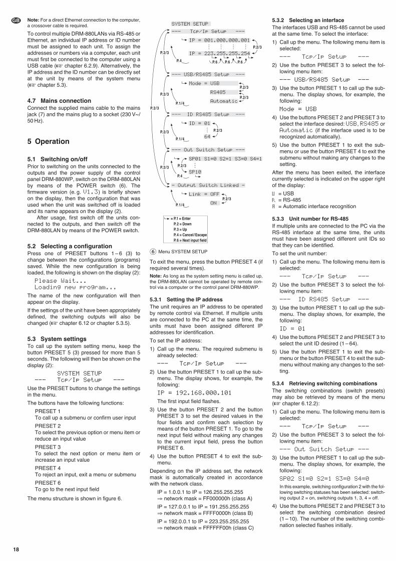
Note: For a direct Ethernet connection to the computer,a crossover cable is required.
To control multiple DRM-880LANs via RS-485 orEthernet, an individual IP address or ID numbermust be assigned to each unit. To assign theaddresses or numbers via a computer, each unitmust first be connected to the computer using aUSB cable (� chapter 6.2.9). Alternatively, theIP address and the ID number can be directly setat the unit by means of the system menu(� chapter 5.3).
4.7 Mains connectionConnect the supplied mains cable to the mainsjack (7) and the mains plug to a socket (230 V~/50 Hz).
5 Operation
5.1 Switching on/offPrior to switching on the units connected to theoutputs and the power supply of the controlpanel DRM-880WP, switch on the DRM-880LANby means of the POWER switch (6). Thefirmware version (e. g. V1.3) is briefly shownon the display, then the configuration that wasused when the unit was switched off is loadedand its name appears on the display (2).
After usage, first switch off the units con-nected to the outputs, and then switch off theDRM-880LAN by means of the POWER switch.
5.2 Selecting a configurationPress one of PRESET buttons 1 – 6 (3) tochange between the configurations (programs)saved. While the new configuration is beingloaded, the following is shown on the display (2):
Please Wait...Loading new program...
The name of the new configuration will thenappear on the display.
If the settings of the unit have been appropriatelydefined, the switching outputs will also bechanged (� chapter 6.12 or chapter 5.3.5).
5.3 System settingsTo call up the system setting menu, keep thebutton PRESET 5 (3) pressed for more than 5seconds. The following will then be shown on thedisplay (2):
SYSTEM SETUP--- Tcp/Ip Setup ---
Use the PRESET buttons to change the settingsin the menu.
The buttons have the following functions:
PRESET 1To call up a submenu or confirm user input
PRESET 2To select the previous option or menu item orreduce an input value
PRESET 3To select the next option or menu item orincrease an input value
PRESET 4To reject an input, exit a menu or submenu
PRESET 6To go to the next input field
The menu structure is shown in figure 6.
To exit the menu, press the button PRESET 4 (ifrequired several times).Note: As long as the system setting menu is called up,the DRM-880LAN cannot be operated by remote con-trol via a computer or the control panel DRM-880WP.
5.3.1 Setting the IP addressThe unit requires an IP address to be operatedby remote control via Ethernet. If multiple unitsare connected to the PC at the same time, theunits must have been assigned different IPaddresses for identification.
To set the IP address:
1) Call up the menu. The required submenu isalready selected:
--- Tcp/Ip Setup ---
2) Use the button PRESET 1 to call up the sub-menu. The display shows, for example, thefollowing:
IP = 192.168.000.101
The first input field flashes.
3) Use the button PRESET 2 and the buttonPRESET 3 to set the desired values in thefour fields and confirm each selection bymeans of the button PRESET 1. To go to thenext input field without making any changesto the current input field, press the buttonPRESET 6.
4) Use the button PRESET 4 to exit the sub-menu.
Depending on the IP address set, the networkmask is automatically created in accordancewith the network class.
IP = 1.0.0.1 to IP = 126.255.255.255⇒ network mask = FF000000h (class A)
IP = 127.0.0.1 to IP = 191.255.255.255⇒ network mask = FFFF0000h (class B)
IP = 192.0.0.1 to IP = 223.255.255.255⇒ network mask = FFFFFF00h (class C)
5.3.2 Selecting an interfaceThe interfaces USB and RS-485 cannot be usedat the same time. To select the interface:
1) Call up the menu. The following menu item isselected:
--- Tcp/Ip Setup ---
2) Use the button PRESET 3 to select the fol-lowing menu item:
--- USB/RS485 Setup ---
3) Use the button PRESET 1 to call up the sub-menu. The display shows, for example, thefollowing:
Mode = USB
4) Use the buttons PRESET 2 and PRESET 3 toselect the interface desired: USB, RS485 orAutomatic (if the interface used is to berecognized automatically).
5) Use the button PRESET 1 to exit the sub-menu or use the button PRESET 4 to exit thesubmenu without making any changes to thesetting.
After the menu has been exited, the interfacecurrently selected is indicated on the upper rightof the display:
= USB= RS-485= Automatic interface recognition
5.3.3 Unit number for RS-485If multiple units are connected to the PC via theRS-485 interface at the same time, the unitsmust have been assigned different unit IDs sothat they can be identified.
To set the unit number:
1) Call up the menu. The following menu item isselected:
--- Tcp/Ip Setup ---
2) Use the button PRESET 3 to select the fol-lowing menu item:
--- ID RS485 Setup ---
3) Use the button PRESET 1 to call up the sub-menu. The display shows, for example, thefollowing:
ID = 01
4) Use the buttons PRESET 2 and PRESET 3 toselect the unit ID desired (1 – 64).
5) Use the button PRESET 1 to exit the sub-menu or the button PRESET 4 to exit the sub-menu without making any changes to the set-ting.
5.3.4 Retrieving switching combinationsThe switching combinations (switch presets)may also be retrieved by means of the menu(� chapter 6.12.2):
1) Call up the menu. The following menu item isselected:
--- Tcp/Ip Setup ---
2) Use the button PRESET 3 to select the fol-lowing menu item:
--- Out Switch Setup ---
3) Use the button PRESET 1 to call up the sub-menu. The display shows, for example, thefollowing:
SP02 S1=0 S2=1 S3=0 S4=0
In this example, switching configuration 2 with the fol-lowing switching statuses has been selected: switch-ing output 2 = on, switching outputs 1, 3, 4 = off.
4) Use the buttons PRESET 2 and PRESET 3 toselect the switching combination desired(1 – 10). The number of the switching combi-nation selected flashes initially.
⑥ Menu SYSTEM SETUP
18
GB
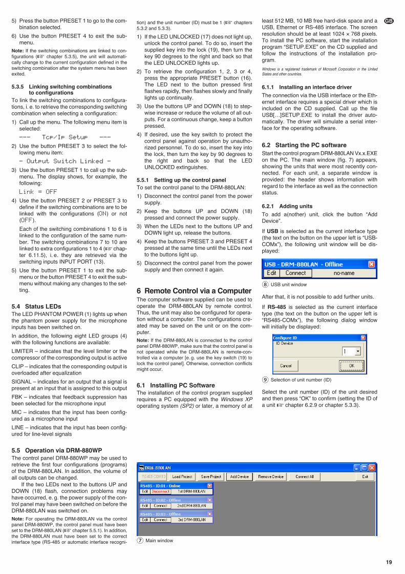
5) Press the button PRESET 1 to go to the com-bination selected.
6) Use the button PRESET 4 to exit the sub-menu.
Note: If the switching combinations are linked to con-figurations (� chapter 5.3.5), the unit will automati-cally change to the current configuration defined in theswitching combination after the system menu has beenexited.
5.3.5 Linking switching combinations to configurations
To link the switching combinations to configura-tions, i. e. to retrieve the corresponding switchingcombination when selecting a configuration:
1) Call up the menu. The following menu item isselected:
--- Tcp/Ip Setup ---
2) Use the button PRESET 3 to select the fol-lowing menu item:
- Output Switch Linked -
3) Use the button PRESET 1 to call up the sub-menu. The display shows, for example, thefollowing:
Link = OFF
4) Use the button PRESET 2 or PRESET 3 todefine if the switching combinations are to belinked with the configurations (ON) or not(OFF).
Each of the switching combinations 1 to 6 islinked to the configuration of the same num-ber. The switching combinations 7 to 10 arelinked to extra configurations 1 to 4 (� chap-ter 6.11.5), i. e. they are retrieved via theswitching inputs INPUT PORT (13).
5) Use the button PRESET 1 to exit the sub-menu or the button PRESET 4 to exit the sub-menu without making any changes to the set-ting.
5.4 Status LEDsThe LED PHANTOM POWER (1) lights up whenthe phantom power supply for the microphoneinputs has been switched on.
In addition, the following eight LED groups (4)with the following functions are available:
LIMITER – indicates that the level limiter or thecompressor of the corresponding output is active
CLIP – indicates that the corresponding output isoverloaded after equalization
SIGNAL – indicates for an output that a signal ispresent at an input that is assigned to this output
FBK – indicates that feedback suppression hasbeen selected for the microphone input
MIC – indicates that the input has been config-ured as a microphone input
LINE – indicates that the input has been config-ured for line-level signals
5.5 Operation via DRM-880WPThe control panel DRM-880WP may be used toretrieve the first four configurations (programs)of the DRM-880LAN. In addition, the volume ofall outputs can be changed.
If the two LEDs next to the buttons UP andDOWN (18) flash, connection problems mayhave occurred, e. g. the power supply of the con-trol panel may have been switched on before theDRM-880LAN was switched on.
Note: For operating the DRM-880LAN via the controlpanel DRM-880WP, the control panel must have beenset to the DRM-880LAN (� chapter 5.5.1). In addition,the DRM-880LAN must have been set to the correctinterface type (RS-485 or automatic interface recogni-
tion) and the unit number (ID) must be 1 (� chapters5.3.2 and 5.3.3).
1) If the LED UNLOCKED (17) does not light up,unlock the control panel. To do so, insert thesupplied key into the lock (19), then turn thekey 90 degrees to the right and back so thatthe LED UNLOCKED lights up.
2) To retrieve the configuration 1, 2, 3 or 4,press the appropriate PRESET button (16).The LED next to the button pressed firstflashes rapidly, then flashes slowly and finallylights up continually.
3) Use the buttons UP and DOWN (18) to step-wise increase or reduce the volume of all out-puts. For a continuous change, keep a buttonpressed.
4) If desired, use the key switch to protect thecontrol panel against operation by unautho-rized personnel. To do so, insert the key intothe lock, then turn the key by 90 degrees tothe right and back so that the LEDUNLOCKED extinguishes.
5.5.1 Setting up the control panelTo set the control panel to the DRM-880LAN:
1) Disconnect the control panel from the powersupply.
2) Keep the buttons UP and DOWN (18)pressed and connect the power supply.
3) When the LEDs next to the buttons UP andDOWN light up, release the buttons.
4) Keep the buttons PRESET 3 and PRESET 4pressed at the same time until the LEDs nextto the buttons light up.
5) Disconnect the control panel from the powersupply and then connect it again.
6 Remote Control via a ComputerThe computer software supplied can be used tooperate the DRM-880LAN by remote control.Thus, the unit may also be configured for opera-tion without a computer. The configurations cre-ated may be saved on the unit or on the com-puter. Note: If the DRM-880LAN is connected to the controlpanel DRM-880WP, make sure that the control panel isnot operated while the DRM-880LAN is remote-con-trolled via a computer [e. g. use the key switch (19) tolock the control panel]. Otherwise, connection conflictsmight occur.
6.1 Installing PC SoftwareThe installation of the control program suppliedrequires a PC equipped with the Windows XPoperating system (SP2) or later, a memory of at
least 512 MB, 10 MB free hard-disk space and aUSB, Ethernet or RS-485 interface. The screenresolution should be at least 1024 × 768 pixels.To install the PC software, start the installationprogram “SETUP.EXE” on the CD supplied andfollow the instructions of the installation pro-gram.
Windows is a registered trademark of Microsoft Corporation in the UnitedStates and other countries.
6.1.1 Installing an interface driver
The connection via the USB interface or the Eth-ernet interface requires a special driver which isincluded on the CD supplied. Call up the fileUSB[…]SETUP.EXE to install the driver auto-matically. The driver will simulate a serial inter-face for the operating software.
6.2 Starting the PC softwareStart the control program DRM-880LAN Vx.x.EXEon the PC. The main window (fig. 7) appears,showing the units that were most recently con-nected. For each unit, a separate window isprovided: the header shows information withregard to the interface as well as the connectionstatus.
6.2.1 Adding units
To add a(nother) unit, click the button “AddDevice”.
If USB is selected as the current interface type(the text on the button on the upper left is “USB-COMx”), the following unit window will be dis-played:
After that, it is not possible to add further units.
If RS-485 is selected as the current interfacetype (the text on the button on the upper left is“RS485-COMx”), the following dialog windowwill initially be displayed:
Select the unit number (ID) of the unit desiredand then press “OK” to confirm (setting the ID ofa unit � chapter 6.2.9 or chapter 5.3.3).
⑨ Selection of unit number (ID)
⑧ USB unit window
19
GB
⑦ Main window
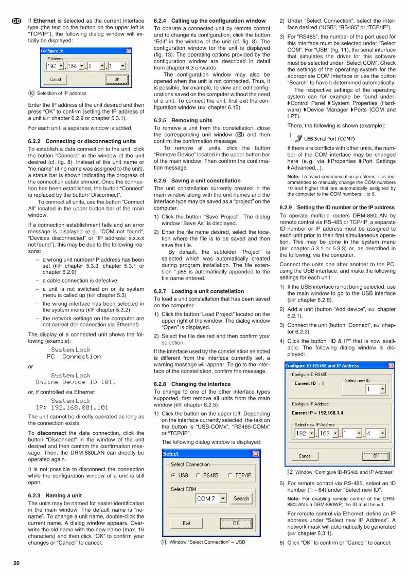
If Ethernet is selected as the current interfacetype (the text on the button on the upper left is“TCP/ IP”), the following dialog window will ini-tially be displayed:
Enter the IP address of the unit desired and thenpress “OK” to confirm (setting the IP address ofa unit � chapter 6.2.9 or chapter 5.3.1).
For each unit, a separate window is added.
6.2.2 Connecting or disconnecting unitsTo establish a data connection to the unit, clickthe button “Connect” in the window of the unitdesired (cf. fig. 8). Instead of the unit name or“no-name” (if no name was assigned to the unit),a status bar is shown indicating the progress ofthe connection establishment. Once the connec-tion has been established, the button “Connect”is replaced by the button “Disconnect”.
To connect all units, use the button “ConnectAll” located in the upper button bar of the mainwindow.
If a connection establishment fails and an errormessage is displayed (e. g. “COM not found”,“Devices disconnected” or “IP address: x.x.x.xnot found”), this may be due to the following rea-sons:
– a wrong unit number/ IP address has beenset (� chapter 5.3.3, chapter 5.3.1 orchapter 6.2.9)
– a cable connection is defective
– a unit is not switched on or its systemmenu is called up (� chapter 5.3)
– the wrong interface has been selected inthe system menu (� chapter 5.3.2)
– the network settings on the computer arenot correct (for connection via Ethernet)
The display of a connected unit shows the fol-lowing (example):
System LockPC Connection
or
System LockOnline Device ID [01]
or, if controlled via Ethernet
System LockIP: 192.168.001.101
The unit cannot be directly operated as long asthe connection exists.
To disconnect the data connection, click thebutton “Disconnect” in the window of the unitdesired and then confirm the confirmation mes-sage. Then, the DRM-880LAN can directly beoperated again.
It is not possible to disconnect the connectionwhile the configuration window of a unit is stillopen.
6.2.3 Naming a unitThe units may be named for easier identificationin the main window. The default name is “no-name”. To change a unit name, double-click thecurrent name. A dialog window appears. Over-write the old name with the new name (max. 16characters) and then click “OK” to confirm yourchanges or “Cancel” to cancel.
6.2.4 Calling up the configuration window To operate a connected unit by remote controland to change its configuration, click the button“Edit” in the window of the unit (cf. fig. 8). Theconfiguration window for the unit is displayed(fig. 13). The operating options provided by theconfiguration window are described in detailfrom chapter 6.3 onwards.
The configuration window may also beopened when the unit is not connected. Thus, itis possible, for example, to view and edit config-urations saved on the computer without the needof a unit. To connect the unit, first exit the con-figuration window (� chapter 6.15).
6.2.5 Removing unitsTo remove a unit from the constellation, closethe corresponding unit window (⊠) and thenconfirm the confirmation message.
To remove all units, click the button“Remove Device” located in the upper button barof the main window. Then confirm the confirma-tion message.
6.2.6 Saving a unit constellationThe unit constellation currently created in themain window along with the unit names and theinterface type may be saved as a “project” on thecomputer.
1) Click the button “Save Project”. The dialogwindow “Save As” is displayed.
2) Enter the file name desired, select the loca-tion where the file is to be saved and thensave the file.
By default, the subfolder “Project” isselected which was automatically createdduring program installation. The file exten-sion *.p88 is automatically appended to thefile name entered.
6.2.7 Loading a unit constellationTo load a unit constellation that has been savedon the computer:
1) Click the button “Load Project” located on theupper right of the window. The dialog window“Open” is displayed.
2) Select the file desired and then confirm yourselection.
If the interface used by the constellation selectedis different from the interface currently set, awarning message will appear. To go to the inter-face of the constellation, confirm the message.
6.2.8 Changing the interfaceTo change to one of the other interface typessupported, first remove all units from the mainwindow (� chapter 6.2.5).
1) Click the button on the upper left. Dependingon the interface currently selected, the text onthe button is “USB-COMx”, “RS485-COMx”or “TCP/ IP”.
The following dialog window is displayed:
2) Under “Select Connection”, select the inter-face desired (“USB”, “RS485” or “TCP/ IP”).
3) For “RS485”, the number of the port used forthis interface must be selected under “SelectCOM”. For “USB” (fig. 11), the serial interfacethat simulates the driver for this softwaremust be selected under “Select COM”. Checkthe settings of the operating system for theappropriate COM interface or use the button“Search” to have it determined automatically.
The respective settings of the operatingsystem can for example be found under:�Control Panel �System Properties (Hard-ware) �Device Manager �Ports (COM andLPT).
There, the following is shown (example):
If there are conflicts with other units, the num-ber of the COM interface may be changedhere (e. g. via �Properties �Port Settings�Advanced...).
Note: To avoid communication problems, it is rec-ommended to manually change the COM numbers10 and higher that are automatically assigned bythe computer to the COM numbers 1 to 9.
6.2.9 Setting the ID number or the IP address
To operate multiple routers DRM-880LAN byremote control via RS-485 or TCP/ IP, a separateID number or IP address must be assigned toeach unit prior to their first simultaneous opera-tion. This may be done in the system menu(� chapter 5.3.1 or 5.3.3) or, as described inthe following, via the computer.
Connect the units one after another to the PC,using the USB interface, and make the followingsettings for each unit:
1) If the USB interface is not being selected, usethe main window to go to the USB interface(� chapter 6.2.8).
2) Add a unit (button “Add device”, � chapter6.2.1).
3) Connect the unit (button “Connect”, � chap-ter 6.2.2).
4) Click the button “ID & IP” that is now avail-able. The following dialog window is dis-played:
5) For remote control via RS-485, select an IDnumber (1 – 64) under “Select new ID”.
Note: For enabling remote control of the DRM-880LAN via DRM-880WP, the ID must be = 1.
For remote control via Ethernet, define an IPaddress under “Select new IP Address”. Anetwork mask will automatically be generated(� chapter 5.3.1).
6) Click “OK” to confirm or “Cancel” to cancel.
⑫ Window “Configure ID-RS485 and IP Address”
⑪ Window “Select Connection” – USB
⑩ Selection of IP address
20
GB
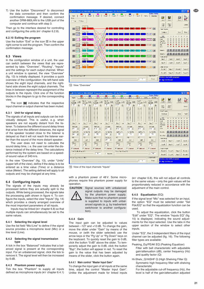
21
GB7) Use the button “Disconnect” to disconnectthe data connection and then confirm theconfirmation message. If desired, connectanother DRM-880LAN to the USB port of thecomputer and continue with step 3.
Then go to the interface desired for controllingand configuring the units (� chapter 6.2.8).
6.2.10 Exiting the programUse the button “Exit” or the icon ⊠ in the upperright corner to exit the program. Then confirm theconfirmation message.
6.3 ViewsIn the configuration window of a unit, the usercan switch between the views that are repre-sented by tabs: “Overview”, “Routing”, “Inputs”and the settings for each output channel. Whena unit window is opened, the view “Overview”(fig. 13) is initially displayed. It provides a quickoverview of the configuration: the left-hand sideshows the eight input channels, and the right-hand side shows the eight output channels. Thelines in between represent the assignment of theoutputs to the inputs. Click one of the functionblocks in the diagram to go to the correspondingview.
The icon indicates that the respectiveinput channel or output channel has been muted.
6.3.1 Unit for signal delayThe signals of all inputs and outputs can be indi-vidually delayed. This is useful, e. g. whenspeakers are not equally distant from the lis-tener. To balance the different sound delay timesthat arise from the different distances, the signalof the speaker located close to the listener isdelayed so that it will not reach the listener ear-lier than the sound of the more distant speaker.
The user does not need to calculate thesound delay time, i. e. the user can enter the dis-tance instead of the delay time. The calculationsperformed by the system are based on a speed-of-sound value of 340 m/s.
In the view “Overview” (fig. 13), under “Units”(upper left of the view), define if the delay is to beentered as a time value (Time) or a distancevalue (Meter). The setting defined will apply to alloutputs and may be changed at any time.
6.4 Configuring inputsThe signals of the inputs may already beprocessed before they are actually split to theoutputs. While being processed, the signals takethe processing path shown in figure 4. To con-figure the inputs, select the view “Inputs” (fig. 14)which provides a clearly arranged overview ofthe most important parameters of all inputs.
Inputs may be linked (� chapter 6.8) so thatmultiple inputs can simultaneously be set to thesame values.
6.4.1 Selecting the signal levelUse the list field “Mic / Line” to define if the signalsource provides a microphone level (Mic) or aline level (Line).
6.4.2 Selecting the signal transmissiontype
A tick in the box “Balanced” indicates that a bal-anced signal is present at the correspondinginput. For an unbalanced signal, click the tick toremove it. The signal level will then be increasedby 6 dB.
6.4.3 Phantom power supplyTick the box “Phantom” to supply all inputsdefined as microphone inputs (� chapter 6.4.1)
with a phantom power of 48 V. Some micro-phones require this phantom power supply foroperation.
6.4.4 GainThe input gain can be adjusted to valuesbetween -127 and +12 dB. To change the gain,move the slider under “Gain” by means of themouse, or (with the slider selected) use thearrow keys or the “Pg Up” or “Pg Down” keys onthe keyboard. To quickly reset the gain to 0 dB,click the button “0 dB” above the slider. To tem-porarily adjust the gain to 0 dB, click the button“Byp”; the button will appear in red. To reset thegain to the value that has been adjusted bymeans of the slider, click the button again.
6.4.4.1 Main control “Master Input Gain”To change the input gain of all inputs at the sametime, adjust the control “Master Input Gain”.Unlike the adjustment made for linked inputs
(� chapter 6.8), this will not adjust all controlsto the same values – only the gain values will beproportionately reduced in accordance with theadjustment of the main control.
6.4.5 Equalization (EQ)
If the signal level “Mic” was selected for an input,the option “EQ” must be selected under “SelFbk/EQ” so that the equalization function can beused.
To adjust the equalization, click the button“Edit” under “EQ”. The window “Inputs EQ” (fig.15) is displayed, indicating the sound adjust-ments for the input selected. Use the tabs in theupper section of the window to select otherinputs.
Under “EQ”, the 3 independent filters of the inputchannel can be adjusted (fig. 16). The followingfilter types are available:
Peaking_Eq / PEAK EQ (Peaking Equalizer)Filter with bell characteristic with adjustablegain/attenuation (dB), center frequency (Hz)and quality factor (Q)
Hi-Shelv_Q / HiSHF Q (High Shelving Filter Q)Symmetric high frequency filter with shelvingcharacteristicFor the adjustable cut-off frequency (Hz), thelevel is half of the gain/attenuation adjusted
CAUTION Signal sources with unbalancedsignal outputs may be damagedby the phantom power supply.Make sure that no phantom poweris supplied to inputs with unbal-anced signals (e. g. by inadvertentswitchover to another configura-tion).
⑭ View of the input channels “Inputs”
⑬ View “Overview”
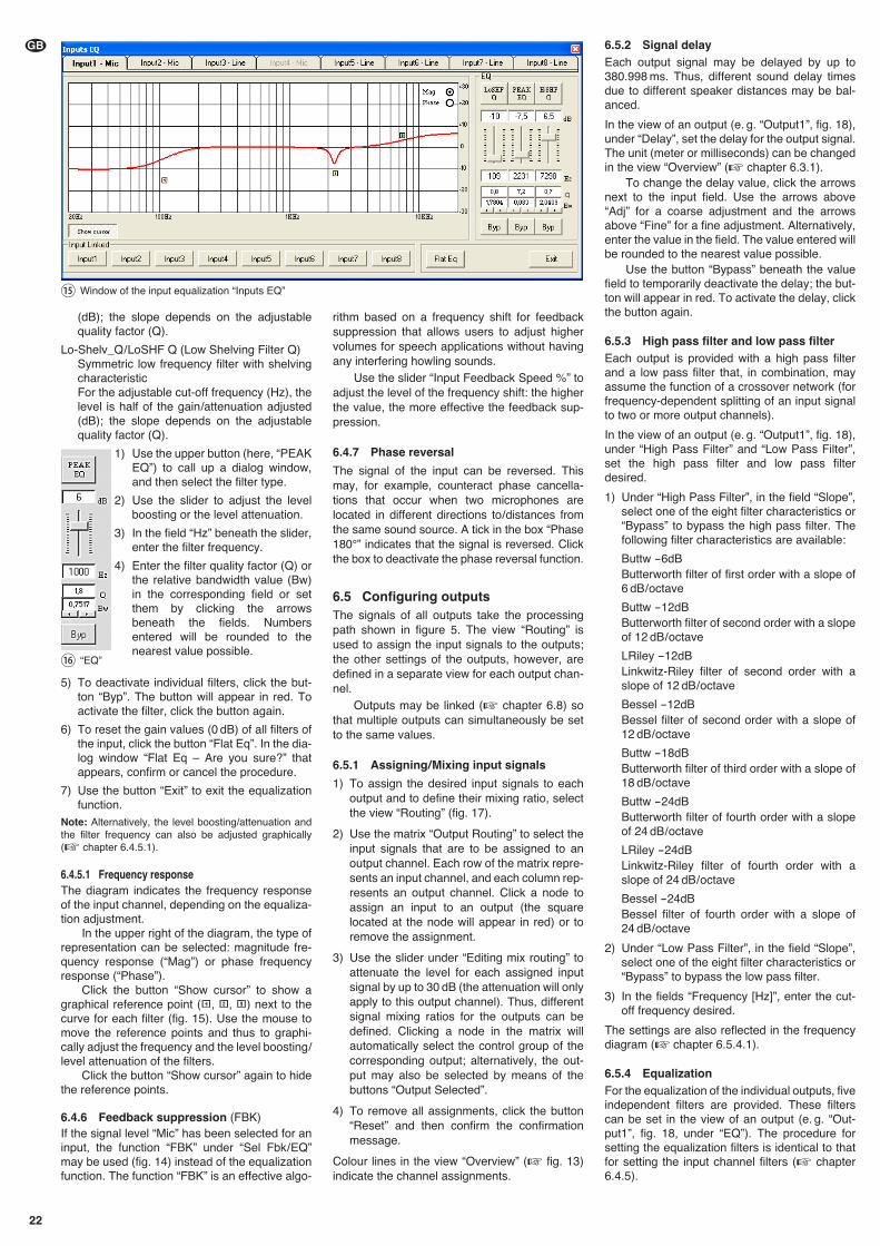
22
GB 6.5.2 Signal delayEach output signal may be delayed by up to380.998 ms. Thus, different sound delay timesdue to different speaker distances may be bal-anced.
In the view of an output (e. g. “Output1”, fig. 18),under “Delay”, set the delay for the output signal.The unit (meter or milliseconds) can be changedin the view “Overview” (� chapter 6.3.1).
To change the delay value, click the arrowsnext to the input field. Use the arrows above“Adj” for a coarse adjustment and the arrowsabove “Fine” for a fine adjustment. Alternatively,enter the value in the field. The value entered willbe rounded to the nearest value possible.
Use the button “Bypass” beneath the valuefield to temporarily deactivate the delay; the but-ton will appear in red. To activate the delay, clickthe button again.
6.5.3 High pass filter and low pass filterEach output is provided with a high pass filterand a low pass filter that, in combination, mayassume the function of a crossover network (forfrequency-dependent splitting of an input signalto two or more output channels).
In the view of an output (e. g. “Output1”, fig. 18),under “High Pass Filter” and “Low Pass Filter”,set the high pass filter and low pass filterdesired.
1) Under “High Pass Filter”, in the field “Slope”,select one of the eight filter characteristics or“Bypass” to bypass the high pass filter. Thefollowing filter characteristics are available:
Buttw -6dBButterworth filter of first order with a slope of6 dB / octave
Buttw -12dBButterworth filter of second order with a slopeof 12 dB / octave
LRiley -12dBLinkwitz-Riley filter of second order with aslope of 12 dB / octave
Bessel -12dBBessel filter of second order with a slope of12 dB / octave
Buttw -18dBButterworth filter of third order with a slope of18 dB / octave
Buttw -24dBButterworth filter of fourth order with a slopeof 24 dB / octave
LRiley -24dBLinkwitz-Riley filter of fourth order with aslope of 24 dB / octave
Bessel -24dBBessel filter of fourth order with a slope of24 dB / octave
2) Under “Low Pass Filter”, in the field “Slope”,select one of the eight filter characteristics or“Bypass” to bypass the low pass filter.
3) In the fields “Frequency [Hz]”, enter the cut-off frequency desired.
The settings are also reflected in the frequencydiagram (� chapter 6.5.4.1).
6.5.4 EqualizationFor the equalization of the individual outputs, fiveindependent filters are provided. These filterscan be set in the view of an output (e. g. “Out-put1”, fig. 18, under “EQ”). The procedure forsetting the equalization filters is identical to thatfor setting the input channel filters (� chapter6.4.5).
(dB); the slope depends on the adjustablequality factor (Q).
Lo-Shelv_Q / LoSHF Q (Low Shelving Filter Q)Symmetric low frequency filter with shelvingcharacteristicFor the adjustable cut-off frequency (Hz), thelevel is half of the gain/attenuation adjusted(dB); the slope depends on the adjustablequality factor (Q).
1) Use the upper button (here, “PEAKEQ”) to call up a dialog window,and then select the filter type.
2) Use the slider to adjust the levelboosting or the level attenuation.
3) In the field “Hz” beneath the slider,enter the filter frequency.
4) Enter the filter quality factor (Q) orthe relative bandwidth value (Bw)in the corresponding field or setthem by clicking the arrowsbeneath the fields. Numbersentered will be rounded to thenearest value possible.
5) To deactivate individual filters, click the but-ton “Byp”. The button will appear in red. Toactivate the filter, click the button again.
6) To reset the gain values (0 dB) of all filters ofthe input, click the button “Flat Eq”. In the dia-log window “Flat Eq – Are you sure?” thatappears, confirm or cancel the procedure.
7) Use the button “Exit” to exit the equalizationfunction.
Note: Alternatively, the level boosting/attenuation andthe filter frequency can also be adjusted graphically(� chapter 6.4.5.1).
6.4.5.1 Frequency responseThe diagram indicates the frequency responseof the input channel, depending on the equaliza-tion adjustment.
In the upper right of the diagram, the type ofrepresentation can be selected: magnitude fre-quency response (“Mag”) or phase frequencyresponse (“Phase”).
Click the button “Show cursor” to show agraphical reference point ( , , ) next to thecurve for each filter (fig. 15). Use the mouse tomove the reference points and thus to graphi-cally adjust the frequency and the level boosting/level attenuation of the filters.
Click the button “Show cursor” again to hidethe reference points.
6.4.6 Feedback suppression (FBK)If the signal level “Mic” has been selected for aninput, the function “FBK” under “Sel Fbk/ EQ”may be used (fig. 14) instead of the equalizationfunction. The function “FBK” is an effective algo-
rithm based on a frequency shift for feedbacksuppression that allows users to adjust highervolumes for speech applications without havingany interfering howling sounds.
Use the slider “Input Feedback Speed %” toadjust the level of the frequency shift: the higherthe value, the more effective the feedback sup-pression.
6.4.7 Phase reversal
The signal of the input can be reversed. Thismay, for example, counteract phase cancella-tions that occur when two microphones arelocated in different directions to/ distances fromthe same sound source. A tick in the box “Phase180°” indicates that the signal is reversed. Clickthe box to deactivate the phase reversal function.
6.5 Configuring outputsThe signals of all outputs take the processingpath shown in figure 5. The view “Routing” isused to assign the input signals to the outputs;the other settings of the outputs, however, aredefined in a separate view for each output chan-nel.
Outputs may be linked (� chapter 6.8) sothat multiple outputs can simultaneously be setto the same values.
6.5.1 Assigning/ Mixing input signals
1) To assign the desired input signals to eachoutput and to define their mixing ratio, selectthe view “Routing” (fig. 17).
2) Use the matrix “Output Routing” to select theinput signals that are to be assigned to anoutput channel. Each row of the matrix repre-sents an input channel, and each column rep-resents an output channel. Click a node toassign an input to an output (the squarelocated at the node will appear in red) or toremove the assignment.
3) Use the slider under “Editing mix routing” toattenuate the level for each assigned inputsignal by up to 30 dB (the attenuation will onlyapply to this output channel). Thus, differentsignal mixing ratios for the outputs can bedefined. Clicking a node in the matrix willautomatically select the control group of thecorresponding output; alternatively, the out-put may also be selected by means of thebuttons “Output Selected”.
4) To remove all assignments, click the button“Reset” and then confirm the confirmationmessage.
Colour lines in the view “Overview” (� fig. 13)indicate the channel assignments.
⑯ “EQ”
⑮ Window of the input equalization “Inputs EQ”
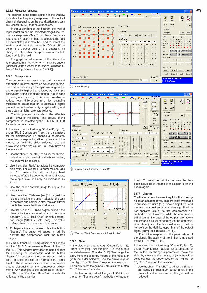
23
GB6.5.4.1 Frequency response
The diagram in the upper section of the windowindicates the frequency response of the outputchannel, depending on the equalization and gain(� chapter 6.5.6) that have been set.
In the upper right of the diagram, the type ofrepresentation can be selected: magnitude fre-quency response (“Mag”) or phase frequencyresponse (“Phase”). If “Mag” is selected, the fieldbeneath “Step dB” may be used to select thescaling and the field beneath “Offset dB” toselect the vertical shift of the diagram. Tochange a value, click the up or down arrow but-tons next to the field.
For graphical adjustment of the filters, thereference points ( , , , , ) may be shown[identical to the procedure for the equalization fil-ters of the inputs (� chapter 6.4.5.1)].
6.5.5 Compressor
The compressor reduces the dynamic range andattenuates the level above an adjustable thresh-old. This is necessary if the dynamic range of theaudio signal is higher than allowed by the ampli-fier system or the listening situation (e. g. in caseof background music). It is also possible toreduce level differences (e. g. for changingmicrophone distances) or to attenuate signalpeaks in order to allow a higher gain setting andthus obtain a higher average volume.
The compressor responds to the effectivevalue (RMS) of the signal. The activity of thecompressor is indicated by the LED LIMITER (4)for each output channel.
In the view of an output (e. g. “Output1”, fig. 18),under “RMS Compressor”, set the parametersfor the compressor. To change a parameter,move the corresponding slider by means of themouse, or (with the slider selected) use thearrow keys or the “Pg Up” or “Pg Down” keys onthe keyboard.
1) Use the slider “Thr [dBu]” to adjust the thresh-old value. If this threshold value is exceeded,the gain will be reduced.
2) Use the slider “Ratio” to adjust the compres-sion ratio. For example, a compression ratioof 10 : 1 means that with an input levelincrease of 20 dB above the threshold value,the output level will only be increased by2 dB.
3) Use the slider “Attack [ms]” to adjust theattack time.
4) Use the slider “Release [sec]” to adjust therelease time, i. e. the time it takes for the gainto reach its original value after the signal levelhas fallen below the threshold value.
5) Use the slider “S / H Knee [%]” to define if thechange to the compression is to be madeabruptly (0 % = Hard Knee) or with a transi-tion range (100 % = Soft Knee). The valuedefines the size of the transition range.
6) To bypass the compressor, click the button“Bypass”. The button will appear in red. Toactivate the compressor, click the buttonagain.
Click the button “RMS Compressor” to call up thewindow “RMS Compressor & Peak Limiter …”(fig. 19). This window provides the same slidersfor adjusting the parameters and the button“Bypass” for bypassing the compressor. In addi-tion, it includes graphics that represent the signallevel of the compressor input and compressoroutput, depending on the compressor adjust-ments. Any changes to the parameters “Thresh-old”, “Ratio” or “Soft/ Hard Knee” will be instantlyreflected in the graphics.
6.5.6 Gain
In the view of an output (e. g. “Output1”, fig. 18),under “Lev [dB]”, set the gain, i. e. the outputlevel (between -127 and +18 dB). To change thegain, move the slider by means of the mouse, or(with the slider selected) use the arrow keys orthe “Pg Up” or “Pg Down” keys on the keyboard.To quickly reset the gain to 0 dB, click the button“0 dB” beneath the slider.
To temporarily adjust the gain to 0 dB, clickthe button “Bypass Level”; the button will appear
in red. To reset the gain to the value that hasbeen adjusted by means of the slider, click thebutton again.
6.5.7 LimiterThe limiter allows the user to quickly limit the sig-nal to an adjusted level. This prevents overloadsin subsequent units (e. g. power amplifiers) andprotects the speakers against damage. The lim-iter operates similar to the compressor de -scribed above. However, while the compressorstill allows an increase of the output level abovethe threshold value depending on the compres-sion rate adjusted, the threshold value of the lim-iter defines the definite upper limit of the outputsignal (compression ratio = ∞ : 1).
The limiter responds to the peak values ofthe signal. The activity of the limiter is indicatedby the LED LIMITER (4).
In the view of an output (e. g. “Output1”, fig. 18),under “Peak Limiter”, adjust the parameters forthe limiter. To change a parameter, move theslider by means of the mouse, or (with the sliderselected) use the arrow keys or the “Pg Up” or“Pg Down” keys on the keyboard.
1) Use the slider “Thr [dBu]” to adjust the thresh-old value, i. e. maximum output level. If thisthreshold value is exceeded, the gain will bereduced.
⑲ Window “RMS Compressor & Peak Limiter”
⑰ View “Routing”
⑱ View of output channel “Output1”
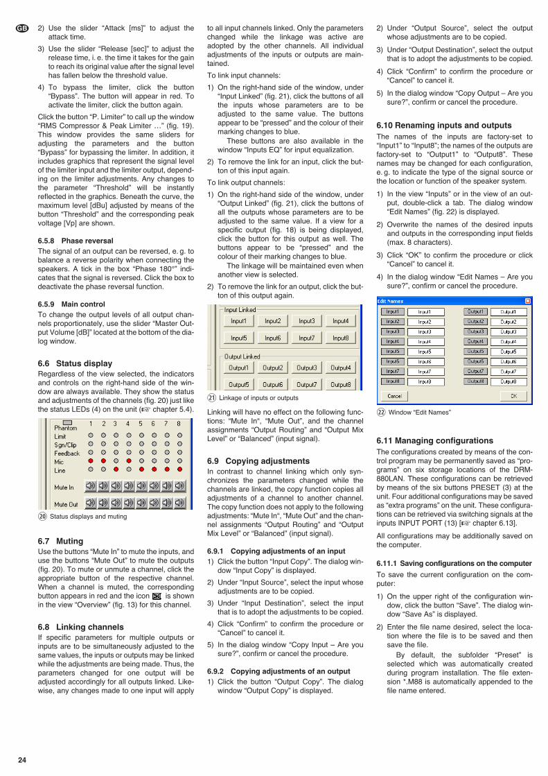
2) Use the slider “Attack [ms]” to adjust theattack time.
3) Use the slider “Release [sec]” to adjust therelease time, i. e. the time it takes for the gainto reach its original value after the signal levelhas fallen below the threshold value.
4) To bypass the limiter, click the button“Bypass”. The button will appear in red. Toactivate the limiter, click the button again.
Click the button “P. Limiter” to call up the window“RMS Compressor & Peak Limiter …” (fig. 19).This window provides the same sliders foradjusting the parameters and the button“Bypass” for bypassing the limiter. In addition, itincludes graphics that represent the signal levelof the limiter input and the limiter output, depend-ing on the limiter adjustments. Any changes tothe parameter “Threshold” will be instantlyreflected in the graphics. Beneath the curve, themaximum level [dBu] adjusted by means of thebutton “Threshold” and the corresponding peakvoltage [Vp] are shown.
6.5.8 Phase reversalThe signal of an output can be reversed, e. g. tobalance a reverse polarity when connecting thespeakers. A tick in the box “Phase 180°” indi-cates that the signal is reversed. Click the box todeactivate the phase reversal function.
6.5.9 Main controlTo change the output levels of all output chan-nels proportionately, use the slider “Master Out-put Volume [dB]” located at the bottom of the dia-log window.
6.6 Status displayRegardless of the view selected, the indicatorsand controls on the right-hand side of the win-dow are always available. They show the statusand adjustments of the channels (fig. 20) just likethe status LEDs (4) on the unit (� chapter 5.4).
6.7 MutingUse the buttons “Mute In” to mute the inputs, anduse the buttons “Mute Out” to mute the outputs(fig. 20). To mute or unmute a channel, click theappropriate button of the respective channel.When a channel is muted, the correspondingbutton appears in red and the icon is shownin the view “Overview” (fig. 13) for this channel.
6.8 Linking channelsIf specific parameters for multiple outputs orinputs are to be simultaneously adjusted to thesame values, the inputs or outputs may be linkedwhile the adjustments are being made. Thus, theparameters changed for one output will beadjusted accordingly for all outputs linked. Like-wise, any changes made to one input will apply
to all input channels linked. Only the parameterschanged while the linkage was active areadopted by the other channels. All individualadjustments of the inputs or outputs are main-tained.
To link input channels:
1) On the right-hand side of the window, under“Input Linked” (fig. 21), click the buttons of allthe inputs whose parameters are to beadjusted to the same value. The buttonsappear to be “pressed” and the colour of theirmarking changes to blue.
These buttons are also available in thewindow “Inputs EQ” for input equalization.
2) To remove the link for an input, click the but-ton of this input again.
To link output channels:
1) On the right-hand side of the window, under“Output Linked” (fig. 21), click the buttons ofall the outputs whose parameters are to beadjusted to the same value. If a view for aspecific output (fig. 18) is being displayed,click the button for this output as well. Thebuttons appear to be “pressed” and thecolour of their marking changes to blue.
The linkage will be maintained even whenanother view is selected.
2) To remove the link for an output, click the but-ton of this output again.
Linking will have no effect on the following func-tions: “Mute In“, “Mute Out”, and the channelassignments “Output Routing” and “Output MixLevel” or “Balanced” (input signal).
6.9 Copying adjustmentsIn contrast to channel linking which only syn-chronizes the parameters changed while thechannels are linked, the copy function copies alladjustments of a channel to another channel.The copy function does not apply to the followingadjustments: “Mute In“, “Mute Out” and the chan-nel assignments “Output Routing” and “OutputMix Level” or “Balanced” (input signal).
6.9.1 Copying adjustments of an input1) Click the button “Input Copy”. The dialog win-
dow “Input Copy” is displayed.
2) Under “Input Source”, select the input whoseadjustments are to be copied.
3) Under “Input Destination”, select the inputthat is to adopt the adjustments to be copied.
4) Click “Confirm” to confirm the procedure or“Cancel” to cancel it.
5) In the dialog window “Copy Input – Are yousure?”, confirm or cancel the procedure.
6.9.2 Copying adjustments of an output1) Click the button “Output Copy”. The dialog
window “Output Copy” is displayed.
2) Under “Output Source”, select the outputwhose adjustments are to be copied.
3) Under “Output Destination”, select the outputthat is to adopt the adjustments to be copied.
4) Click “Confirm” to confirm the procedure or“Cancel” to cancel it.
5) In the dialog window “Copy Output – Are yousure?”, confirm or cancel the procedure.
6.10 Renaming inputs and outputsThe names of the inputs are factory-set to“Input1” to “Input8”; the names of the outputs arefactory-set to “Output1” to “Output8”. Thesenames may be changed for each configuration,e. g. to indicate the type of the signal source orthe location or function of the speaker system.
1) In the view “Inputs” or in the view of an out-put, double-click a tab. The dialog window“Edit Names” (fig. 22) is displayed.
2) Overwrite the names of the desired inputsand outputs in the corresponding input fields(max. 8 characters).
3) Click “OK” to confirm the procedure or click“Cancel” to cancel it.
4) In the dialog window “Edit Names – Are yousure?”, confirm or cancel the procedure.
6.11 Managing configurationsThe configurations created by means of the con-trol program may be permanently saved as “pro-grams” on six storage locations of the DRM-880LAN. These configurations can be retrievedby means of the six buttons PRESET (3) at theunit. Four additional configurations may be savedas “extra programs” on the unit. These configura-tions can be retrieved via switching signals at theinputs INPUT PORT (13) [� chapter 6.13].
All configurations may be additionally saved onthe computer.
6.11.1 Saving configurations on the computer
To save the current configuration on the com-puter:
1) On the upper right of the configuration win-dow, click the button “Save”. The dialog win-dow “Save As” is displayed.
2) Enter the file name desired, select the loca-tion where the file is to be saved and thensave the file.
By default, the subfolder “Preset” isselected which was automatically createdduring program installation. The file exten-sion *.M88 is automatically appended to thefile name entered.
㉒ Window “Edit Names”
㉑ Linkage of inputs or outputs
⑳ Status displays and muting
24
GB
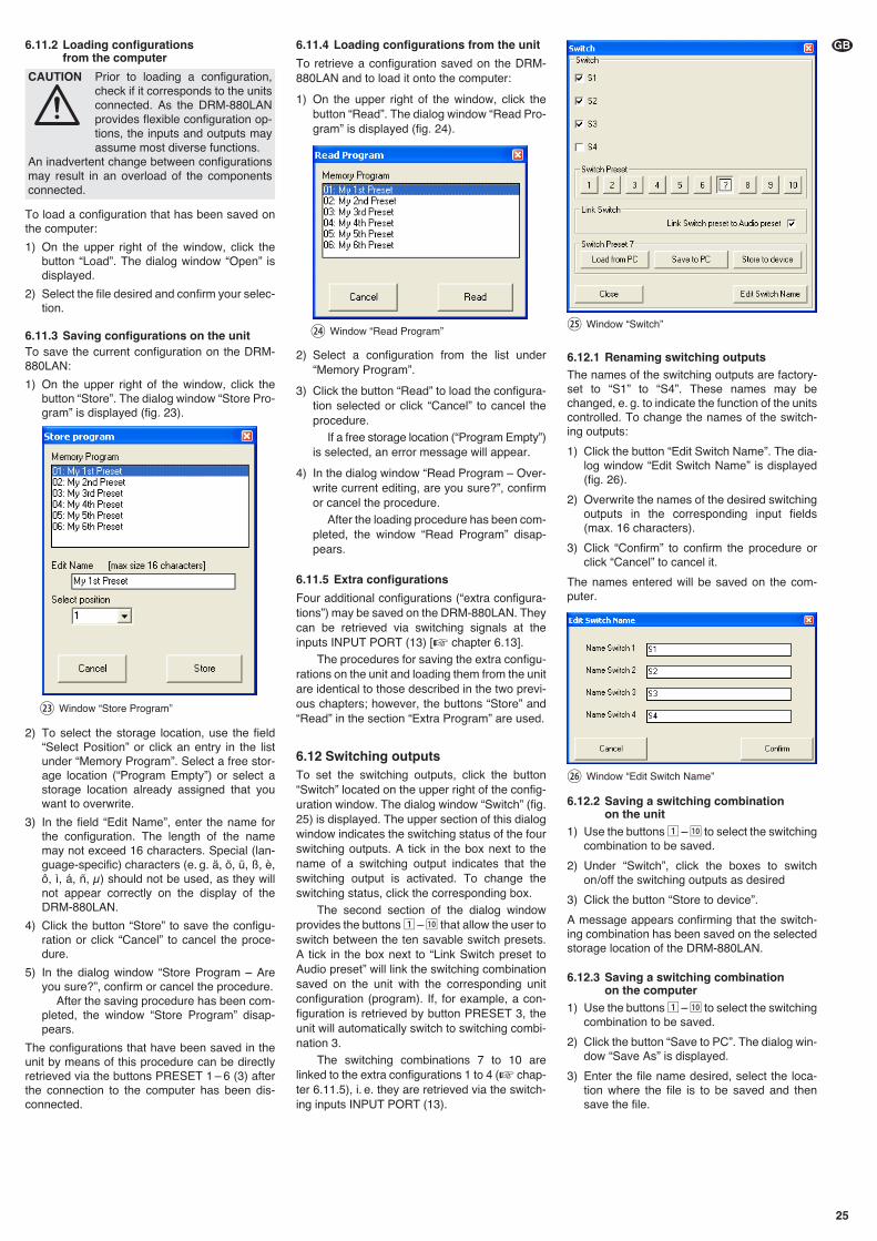
6.11.2 Loading configurations from the computer
To load a configuration that has been saved onthe computer:
1) On the upper right of the window, click thebutton “Load”. The dialog window “Open” isdisplayed.
2) Select the file desired and confirm your selec-tion.
6.11.3 Saving configurations on the unitTo save the current configuration on the DRM-880LAN:
1) On the upper right of the window, click thebutton “Store”. The dialog window “Store Pro-gram” is displayed (fig. 23).
2) To select the storage location, use the field“Select Position” or click an entry in the listunder “Memory Program”. Select a free stor-age location (“Program Empty”) or select astorage location already assigned that youwant to overwrite.
3) In the field “Edit Name”, enter the name forthe configuration. The length of the namemay not exceed 16 characters. Special (lan-guage-specific) characters (e. g. ä, ö, ü, ß, è,ô, ì, á, ñ, μ) should not be used, as they willnot appear correctly on the display of theDRM-880LAN.
4) Click the button “Store” to save the configu-ration or click “Cancel” to cancel the proce-dure.
5) In the dialog window “Store Program – Areyou sure?”, confirm or cancel the procedure.
After the saving procedure has been com-pleted, the window “Store Program” disap-pears.
The configurations that have been saved in theunit by means of this procedure can be directlyretrieved via the buttons PRESET 1 – 6 (3) afterthe connection to the computer has been dis-connected.
6.11.4 Loading configurations from the unit
To retrieve a configuration saved on the DRM-880LAN and to load it onto the computer:
1) On the upper right of the window, click thebutton “Read”. The dialog window “Read Pro-gram” is displayed (fig. 24).
2) Select a configuration from the list under“Memory Program”.
3) Click the button “Read” to load the configura-tion selected or click “Cancel” to cancel theprocedure.
If a free storage location (“Program Empty”)is selected, an error message will appear.
4) In the dialog window “Read Program – Over-write current editing, are you sure?”, confirmor cancel the procedure.
After the loading procedure has been com-pleted, the window “Read Program” disap-pears.
6.11.5 Extra configurations
Four additional configurations (“extra configura-tions”) may be saved on the DRM-880LAN. Theycan be retrieved via switching signals at theinputs INPUT PORT (13) [� chapter 6.13].
The procedures for saving the extra configu-rations on the unit and loading them from the unitare identical to those described in the two previ-ous chapters; however, the buttons “Store” and“Read” in the section “Extra Program” are used.
6.12 Switching outputsTo set the switching outputs, click the button“Switch” located on the upper right of the config-uration window. The dialog window “Switch” (fig.25) is displayed. The upper section of this dialogwindow indicates the switching status of the fourswitching outputs. A tick in the box next to thename of a switching output indicates that theswitching output is activated. To change theswitching status, click the corresponding box.
The second section of the dialog windowprovides the buttons 1 – 10 that allow the user toswitch between the ten savable switch presets.A tick in the box next to “Link Switch preset toAudio preset” will link the switching combinationsaved on the unit with the corresponding unitconfiguration (program). If, for example, a con-figuration is retrieved by button PRESET 3, theunit will automatically switch to switching combi-nation 3.
The switching combinations 7 to 10 arelinked to the extra configurations 1 to 4 (� chap-ter 6.11.5), i. e. they are retrieved via the switch-ing inputs INPUT PORT (13).
6.12.1 Renaming switching outputsThe names of the switching outputs are factory-set to “S1” to “S4”. These names may bechanged, e. g. to indicate the function of the unitscontrolled. To change the names of the switch-ing outputs:
1) Click the button “Edit Switch Name”. The dia-log window “Edit Switch Name” is displayed(fig. 26).
2) Overwrite the names of the desired switchingoutputs in the corresponding input fields(max. 16 characters).
3) Click “Confirm” to confirm the procedure orclick “Cancel” to cancel it.
The names entered will be saved on the com-puter.
6.12.2 Saving a switching combination on the unit
1) Use the buttons 1 – 10 to select the switchingcombination to be saved.
2) Under “Switch”, click the boxes to switchon/off the switching outputs as desired
3) Click the button “Store to device”.
A message appears confirming that the switch-ing combination has been saved on the selectedstorage location of the DRM-880LAN.
6.12.3 Saving a switching combination on the computer
1) Use the buttons 1 – 10 to select the switchingcombination to be saved.
2) Click the button “Save to PC”. The dialog win-dow “Save As” is displayed.
3) Enter the file name desired, select the loca-tion where the file is to be saved and thensave the file.
CAUTION Prior to loading a configuration,check if it corresponds to the unitsconnected. As the DRM-880LANprovides flexible configuration op -tions, the inputs and outputs mayassume most diverse functions.
An inadvertent change between configurationsmay result in an overload of the componentsconnected.
㉖ Window “Edit Switch Name”
㉕ Window “Switch”㉔ Window “Read Program”
㉓ Window “Store Program”
25
GB
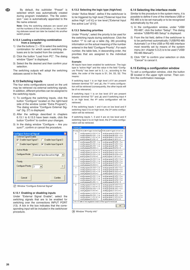
By default, the subfolder “Preset” isselected which was automatically createdduring program installation. The file exten-sion *.swc is automatically appended to thefile name entered. Note: Only the switching statuses are saved andnot the numbers of the combination, i. e. the switch-ing statuses saved can later be loaded into anotherswitch preset.
6.12.4 Loading a switching combinationfrom a computer
1) Use the buttons 1 – 10 to select the switchingcombination for which saved switching sta-tuses are to be loaded from the computer.
2) Click the button “Load from PC”. The dialogwindow “Open” is displayed.
3) Select the file desired and then confirm yourselection.
The switching outputs will adopt the switchingstatuses saved in the file.
6.13 Switching inputsThe four extra configurations saved on the unitmay be retrieved via external switching signals.In addition, different priorities can be assigned tothe switching inputs.
1) To configure the switching inputs, click thebutton “Configure” located on the right-handside of the window (under “Extra Program”).The dialog window “Configure External Sig-nal” (fig. 27) is displayed.
2) After the settings described in chapters6.13.1 to 6.13.3 have been made, click thebutton “Confirm” to confirm your changes.
3) In the dialog window “Configure – Are yousure?”, confirm or cancel the procedure.
6.13.1 Enabling or disabling inputsUnder “External Signal Enable”, select theswitching signals that are to be enabled forswitching over the connections INPUT PORT(13). A tick in the box indicates that the corre-sponding input will be included in the switchoverprocedure.
6.13.2 Selecting the logic type (high / low)
Under “Active Mode”, define if the switchover isto be triggered by high level [“External Input lineactive High” (+5 V)] or low level [“External Inputline active Low” (0 V)].
6.13.3 Selecting priorities
Under “Priority”, select the priority to be used forthe switching inputs during switchover. Click thebutton “?” to call up a table (fig. 28) providinginformation on the actual meaning of the numberentered in the field “Configure Priority”. For eachnumber, the table lists, in descending order, thepriorities that are assigned to the individualinputs.
Example:All inputs have been enabled for switchover. The logictype is “active High” and the value in the field “Config-ure Priority” has been set to 3, i. e., according to thetable, the order of the inputs is S1, S4, S3, S2. Thismeans:
If switching input 1 is on high level (+5 V are presentbetween terminal “S1” and ), the 1st extra configura-tion will be retrieved (consequently, the other inputs willbe of no relevance).
If switching input 1 is on low level (0 V are presentbetween terminal “S1” and ) and if switching input 4is on high level, the 4th extra configuration will beretrieved.
If the switching inputs 1 and 4 are on low level and ifswitching input 3 is on high level, the 3rd extra configu-ration will be retrieved.
If switching inputs 1, 3 and 4 are on low level and ifswitching input 2 is on high level, the 2nd extra configu-ration will be retrieved.
6.14 Selecting the interface modeSimilar to the procedure in the system menu, it ispossible to define if one of the interfaces USB orRS 485 is to be set manually or to be recognizedautomatically by the unit.
1) In the configuration window, under “USB/RS 485”, click the button “Setup”. The dialogwindow “USB/ RS 485 Setup” is displayed.
2) From the list field, define if the switchover isto be performed automatically (“USB/ RS 485Automatic”) or if the USB or RS-485 interfacemost recently set by means of the systemmenu (� chapter 5.3.2) is to be used (“USB/RS 485 Manual”).
3) Click “OK” to confirm your selection or click“Cancel” to cancel it.
6.15 Exiting a configuration windowTo exit a configuration window, click the button⊠ located in the upper right corner. Then con-firm the confirmation message.
㉘ Window “Priority info”
㉗ Window “Configure External Signal”
26
GB
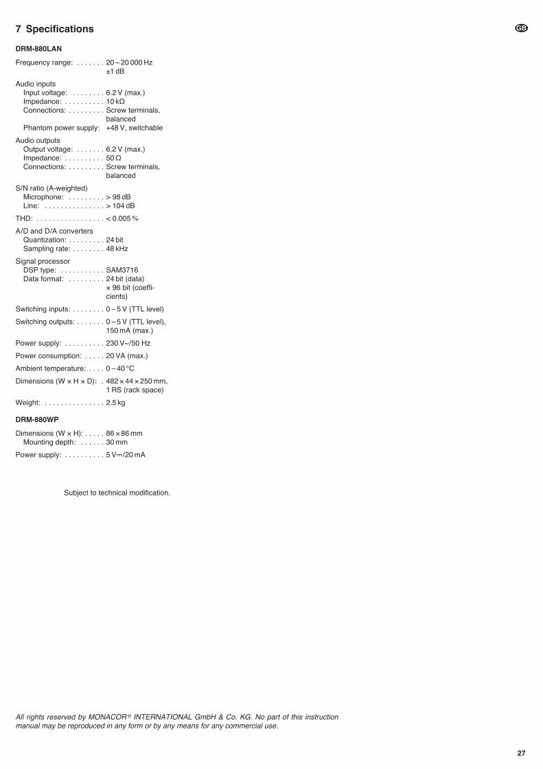
7 Specifications
DRM-880LAN
Frequency range: . . . . . . . 20 – 20 000 Hz±1 dB
Audio inputsInput voltage: . . . . . . . . 6.2 V (max.)Impedance: . . . . . . . . . . 10 kΩConnections: . . . . . . . . . Screw terminals,
balancedPhantom power supply: +48 V, switchable
Audio outputsOutput voltage: . . . . . . . 6.2 V (max.)Impedance: . . . . . . . . . . 50 ΩConnections: . . . . . . . . . Screw terminals,
balanced
S/ N ratio (A-weighted)Microphone: . . . . . . . . . > 98 dBLine: . . . . . . . . . . . . . . . > 104 dB
THD: . . . . . . . . . . . . . . . . . < 0.005 %
A / D and D /A convertersQuantization: . . . . . . . . . 24 bitSampling rate: . . . . . . . . 48 kHz
Signal processorDSP type: . . . . . . . . . . . SAM3716Data format: . . . . . . . . . 24 bit (data)
× 96 bit (coeffi-cients)
Switching inputs: . . . . . . . . 0 – 5 V (TTL level)
Switching outputs: . . . . . . . 0 – 5 V (TTL level),150 mA (max.)
Power supply: . . . . . . . . . . 230 V~ / 50 Hz
Power consumption: . . . . . 20 VA (max.)
Ambient temperature: . . . . 0 – 40 °C
Dimensions (W × H × D): . 482 × 44 × 250 mm,1 RS (rack space)
Weight: . . . . . . . . . . . . . . . 2.5 kg
DRM-880WP
Dimensions (W × H): . . . . . 86 × 86 mmMounting depth: . . . . . . 30 mm
Power supply: . . . . . . . . . . 5 V�/ 20 mA
Subject to technical modification.
27
GB
All rights reserved by MONACOR ® INTERNATIONAL GmbH & Co. KG. No part of this instructionmanual may be reproduced in any form or by any means for any commercial use.
Table des matières1 Eléments et branchements . . . . . . . 28
1.1 Face avant . . . . . . . . . . . . . . . . . . . . . 28
1.2 Face arrière . . . . . . . . . . . . . . . . . . . . . 28
1.3 Unité de commande DRM-880WP . . . 29
2 Conseils dʼutilisation et de sécurité 29
3 Possibilités dʼutilisation . . . . . . . . . . 29
4 Positionnement et branchements . . 29
4.1 Sources de signal . . . . . . . . . . . . . . . . 29
4.2 Amplificateur ou autres appareils . . . . 29
4.3 Signaux externes de commutation . . . 29
4.4 Appareils à gérer . . . . . . . . . . . . . . . . . 29
4.5 Unité de commande DRM-880WP . . . 29
4.6 Ordinateur . . . . . . . . . . . . . . . . . . . . . . 30
4.7 Branchement secteur . . . . . . . . . . . . . 30
5 Utilisation . . . . . . . . . . . . . . . . . . . . . . 30
5.1 Marche/ Arrêt . . . . . . . . . . . . . . . . . . . . 30
5.2 Sélection de la configuration . . . . . . . . 30
5.3 Réglages système . . . . . . . . . . . . . . . . 30
5.3.1 Réglage de lʼadresse IP . . . . . . . . . . . 30
5.3.2 Sélection de lʼinterface . . . . . . . . . . . . 30
5.3.3 Numéro dʼappareil pour RS-485 . . . . . 30
5.3.4 Appeler une combinaison de commutation . . . . . . . . . . . . . . . . . . 31
5.3.5 Combinaisons de commutation couplées aux configurations . . . . . . . . 31
5.4 LEDs dʼétat . . . . . . . . . . . . . . . . . . . . . 31
5.5 Utilisation via DRM-880WP . . . . . . . . . 31
5.5.1 Réglage de lʼunité de commande . . . . 31
6 Utilisation via un ordinateur . . . . . . . 31
6.1 Installation du logiciel PC . . . . . . . . . . 31
6.1.1 Installation du driver interface . . . . . . . 31
6.2 Démarrage du logiciel PC . . . . . . . . . . 31
6.2.1 Ajouter des appareils . . . . . . . . . . . . . 32
6.2.2 Relier ou séparer des appareils . . . . . 32
6.2.3 Nommer un appareil . . . . . . . . . . . . . . 32
6.2.4 Ouvrir la fenêtre de configuration . . . . 32
6.2.5 Retirer des appareils . . . . . . . . . . . . . . 32
6.2.6 Mémoriser une constellation dʼappareils . . . . . . . . . . . . . . . . . . . . . . 32
6.2.7 Charger une constellation dʼappareils . 32
6.2.8 Changement dʼinterface . . . . . . . . . . . 32
6.2.9 Réglage de lʼID ou de lʼadresse IP . . . 32
6.2.10 Quitter le programme . . . . . . . . . . . . 33
6.3 Vues . . . . . . . . . . . . . . . . . . . . . . . . . . 33
6.3.1 Unité de mesure pour la temporisation de signal . . . . . . . . . . . . . . . . . . . . . . . 33
6.4 Configuration des entrées . . . . . . . . . . 33
6.4.1 Sélection du niveau de signal . . . . . . . 33
6.4.2 Sélection du type de transmission de signal . . . . . . . . . . . . . . . . . . . . . . . 33
6.4.3 Alimentation fantôme . . . . . . . . . . . . . 33
6.4.4 Amplification . . . . . . . . . . . . . . . . . . . . 34
6.4.4.1 Réglage principal “Master Input Gain” 34
6.4.5 Egaliseur (EQ) . . . . . . . . . . . . . . . . . . . 34
6.4.5.1 Bande passante . . . . . . . . . . . . . . . . 34
6.4.6 Elimination des interférences (FBK) . . 34
6.4.7 Inversion de phase . . . . . . . . . . . . . . . 34
6.5 Configuration des sorties . . . . . . . . . . 34
6.5.1 Attribution/ Mixage des signaux dʼentrée . . . . . . . . . . . . . . . . . . . . . . . . 34
6.5.2 Temporisation de signal . . . . . . . . . . . 34
6.5.3 Filtres passe-haut et passe-bas . . . . . 35
6.5.4 Egaliseur . . . . . . . . . . . . . . . . . . . . . . . 35
6.5.4.1 Bande passante . . . . . . . . . . . . . . . . 35
6.5.5 Compresseur . . . . . . . . . . . . . . . . . . . .35
6.5.6 Amplification . . . . . . . . . . . . . . . . . . . . 36
6.5.7 Limitation de niveau (Limiter) . . . . . . . 36
6.5.8 Inversion de phase . . . . . . . . . . . . . . . 36
6.5.9 Réglage principal . . . . . . . . . . . . . . . . 36
6.6 LEDs dʼétat . . . . . . . . . . . . . . . . . . . . . 36
6.7 Coupure du son . . . . . . . . . . . . . . . . . . 36
6.8 Couplage des canaux . . . . . . . . . . . . . 36
6.9 Copie des réglages . . . . . . . . . . . . . . . 36
6.9.1 Copie des réglages dʼune entrée . . . . 37
6.9.2 Copie des réglages dʼune sortie . . . . . 37
6.10 Renommer des entrées et sorties . . . . 37
6.11 Gestion des configurations . . . . . . . . . 37
6.11.1 Mémoriser une configuration sur lʼordinateur . . . . . . . . . . . . . . . . . 37
6.11.2 Charger une configuration depuis lʼordinateur . . . . . . . . . . . . . . . 37
6.11.3 Mémoriser la configuration dans lʼappareil . . . . . . . . . . . . . . . . . . 37
6.11.4 Charger des configurations depuis lʼappareil . . . . . . . . . . . . . . . . 37
6.11.5 Configurations extra . . . . . . . . . . . . . 37
6.12 Sorties de commutation . . . . . . . . . . . 37
6.12.1 Renommer les sorties de commutation . . . . . . . . . . . . . . . . . 38
6.12.2 Mémoriser une combinaison de commutation dans lʼappareil . . . . 38
6.12.3 Mémoriser une combinaison de commutation sur lʼordinateur . . . . 38
6.12.4 Charger une combinaison de commutation depuis lʼordinateur . 38
6.13 Entrées de commutation . . . . . . . . . . . 38
6.13.1 Libérer ou verrouiller des entrées . . . 38
6.13.2 Sélectionner le type de logique (high/ low) . . . . . . . . . . . . . . . . . . . . . 38
6.13.3 Sélection des priorités . . . . . . . . . . . . 38
6.14 Sélection du mode dʼinterface . . . . . . . 39
6.15 Fermeture de la fenêtre de configuration . . . . . . . . . . . . . . . . . . 39
7 Caractéristiques techniques . . . . . . 39
Ouvrez le présent livret page 3, dépliable, demanière à visualiser les éléments et branche-ments.
1 Eléments et branchements
1.1 Face avant
1 LED PHANTOM POWER : brille lorsque lʼali-mentation fantôme est allumée pour lesentrées micro
2 Affichage LCD
3 Touches PRESET 1 – 6 pour appeler desconfigurations préalablement mémorisées.Pour appeler le menu pour les réglages sys-tème, maintenez la touche 5 enfoncée plu-sieurs secondes. Vous retrouverez dans lechapitre 5.3 les fonctions des touches pourles réglages système.
4 LEDs dʼétat respectivement pour les canauxdʼentrée et de sortie CH 1 – CH 8
LIMITER : limiteur ou compresseur actif
CLIP : entrée en surcharge (après EQ)
SIGNAL : signal pour le canal de sortie pré-sent
FBK : élimination feedback (larsen) activée
MIC : entrée pour micro
LINE : entrée pour source de signal ligne
5 Prise USB, type B, pour brancher un ordina-teur pour une gestion à distance et une confi-guration du DRM-880LAN
1.2 Face arrière
6 Interrupteur secteur POWER
7 Prise secteur pour brancher à une prise230 V~/50 Hz via le cordon secteur livré
8 Porte-fusible : tout fusible fondu doit impéra-tivement être remplacé par un fusible demême type
9 Prise RJ45 TCP/ IP pour brancher un ordina-teur pour une gestion à distance du DRM-880LAN via Ethernet ; les deux LEDs au-des-sus de la prise indiquent que la connexion estétablie et que les données sont transférées
10 Prise RJ45 RS485 IN pour brancher un ordi-nateur pour une gestion à distance ou lʼunitéde commande à distance DRM-880WP(schéma 3)
11 Prise RJ45 RS485 OUT pour brancher unautre appareil à commander en cas de com-mande à distance via un ordinateur via laprise RS485 IN (10)
12 Sorties de commutation S1 – S4, bornes àvis*
13 Entrées de commutation S1 – S4, bornes àvis* pour appeler des configurations extrapréalablement mémorisées
14 Sorties symétriques signal audio CH 1 – CH 8,bornes à vis*
15 Entrées symétriques signal audio CH 1 – CH 8,bornes à vis*
* On peut retirer une série complète de bornes à vispour un accès plus simple.
28
F
B
CH
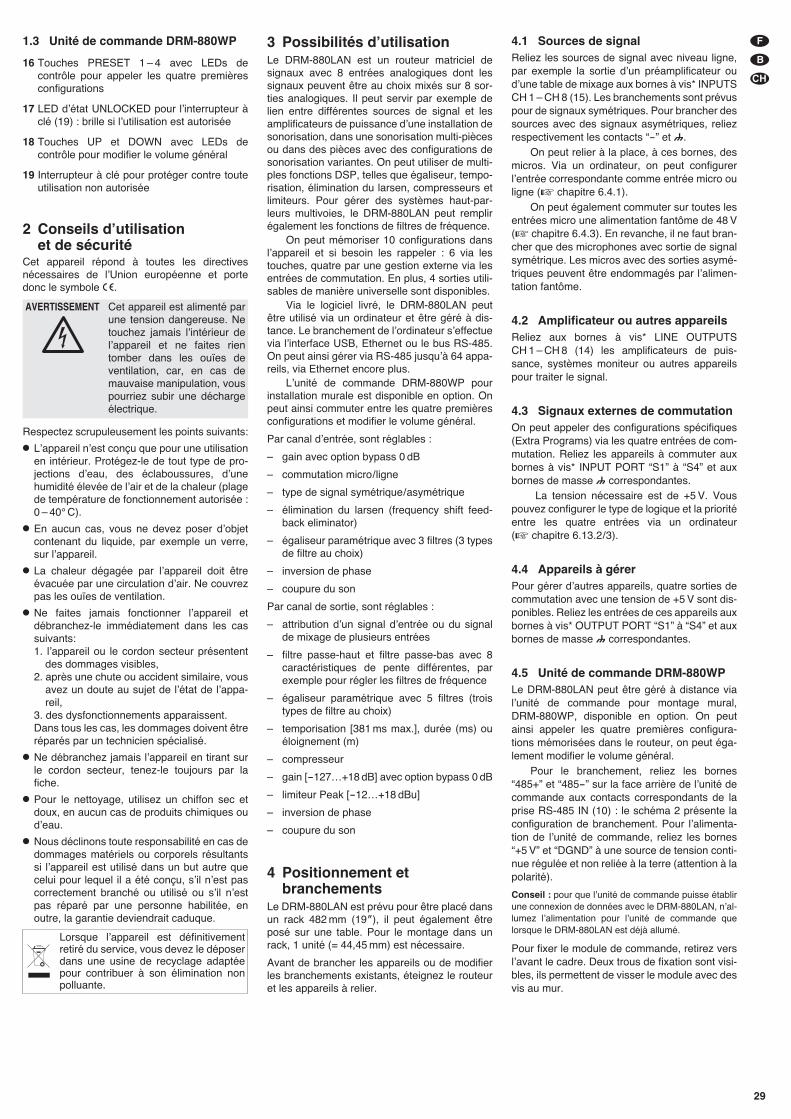
1.3 Unité de commande DRM-880WP
16 Touches PRESET 1 – 4 avec LEDs decontrôle pour appeler les quatre premièresconfigurations
17 LED dʼétat UNLOCKED pour lʼinterrupteur àclé (19) : brille si lʼutilisation est autorisée
18 Touches UP et DOWN avec LEDs decontrôle pour modifier le volume général
19 Interrupteur à clé pour protéger contre touteutilisation non autorisée
2 Conseils dʼutilisation et de sécurité
Cet appareil répond à toutes les directivesnécessaires de lʼUnion européenne et portedonc le symbole �.
Respectez scrupuleusement les points suivants:
� Lʼappareil nʼest conçu que pour une utilisationen intérieur. Protégez-le de tout type de pro-jections dʼeau, des éclaboussures, dʼunehumidité élevée de lʼair et de la chaleur (plagede température de fonctionnement autorisée :0 – 40° C).
� En aucun cas, vous ne devez poser dʼobjetcontenant du liquide, par exemple un verre,sur lʼappareil.
� La chaleur dégagée par lʼappareil doit êtreévacuée par une circulation dʼair. Ne couvrezpas les ouïes de ventilation.
� Ne faites jamais fonctionner lʼappareil etdébranchez-le immédiatement dans les cassuivants:1. lʼappareil ou le cordon secteur présentent
des dommages visibles,2. après une chute ou accident similaire, vous
avez un doute au sujet de lʼétat de lʼappa-reil,
3. des dysfonctionnements apparaissent.Dans tous les cas, les dommages doivent êtreréparés par un technicien spécialisé.
� Ne débranchez jamais lʼappareil en tirant surle cordon secteur, tenez-le toujours par lafiche.
� Pour le nettoyage, utilisez un chiffon sec etdoux, en aucun cas de produits chimiques oudʼeau.
� Nous déclinons toute responsabilité en cas dedommages matériels ou corporels résultantssi lʼappareil est utilisé dans un but autre quecelui pour lequel il a été conçu, sʼil nʼest pascorrectement branché ou utilisé ou sʼil nʼestpas réparé par une personne habilitée, enoutre, la garantie deviendrait caduque.
3 Possibilités dʼutilisationLe DRM-880LAN est un routeur matriciel designaux avec 8 entrées analogiques dont lessignaux peuvent être au choix mixés sur 8 sor-ties analogiques. Il peut servir par exemple delien entre différentes sources de signal et lesamplificateurs de puissance dʼune installation desonorisation, dans une sonorisation multi-piècesou dans des pièces avec des configurations desonorisation variantes. On peut utiliser de multi-ples fonctions DSP, telles que égaliseur, tempo-risation, élimination du larsen, compresseurs etlimiteurs. Pour gérer des systèmes haut-par-leurs multivoies, le DRM-880LAN peut remplirégalement les fonctions de filtres de fréquence.
On peut mémoriser 10 configurations danslʼappareil et si besoin les rappeler : 6 via lestouches, quatre par une gestion externe via lesentrées de commutation. En plus, 4 sorties utili-sables de manière universelle sont disponibles.
Via le logiciel livré, le DRM-880LAN peutêtre utilisé via un ordinateur et être géré à dis-tance. Le branchement de lʼordinateur sʼeffectuevia lʼinterface USB, Ethernet ou le bus RS-485.On peut ainsi gérer via RS-485 jusquʼà 64 appa-reils, via Ethernet encore plus.
Lʼunité de commande DRM-880WP pourinstallation murale est disponible en option. Onpeut ainsi commuter entre les quatre premièresconfigurations et modifier le volume général.
Par canal dʼentrée, sont réglables :
– gain avec option bypass 0 dB
– commutation micro/ ligne
– type de signal symétrique/ asymétrique
– élimination du larsen (frequency shift feed-back eliminator)
– égaliseur paramétrique avec 3 filtres (3 typesde filtre au choix)
– inversion de phase
– coupure du son
Par canal de sortie, sont réglables :
– attribution dʼun signal dʼentrée ou du signalde mixage de plusieurs entrées
– filtre passe-haut et filtre passe-bas avec 8caractéristiques de pente différentes, parexemple pour régler les filtres de fréquence
– égaliseur paramétrique avec 5 filtres (troistypes de filtre au choix)
– temporisation [381 ms max.], durée (ms) ouéloignement (m)
– compresseur
– gain [-127…+18 dB] avec option bypass 0 dB
– limiteur Peak [-12…+18 dBu]
– inversion de phase
– coupure du son
4 Positionnement etbranchements
Le DRM-880LAN est prévu pour être placé dansun rack 482 mm (19″), il peut également êtreposé sur une table. Pour le montage dans unrack, 1 unité (= 44,45 mm) est nécessaire.
Avant de brancher les appareils ou de modifierles branchements existants, éteignez le routeuret les appareils à relier.
4.1 Sources de signalReliez les sources de signal avec niveau ligne,par exemple la sortie dʼun préamplificateur oudʼune table de mixage aux bornes à vis* INPUTSCH 1 – CH 8 (15). Les branchements sont prévuspour de signaux symétriques. Pour brancher dessources avec des signaux asymétriques, reliezrespectivement les contacts “-” et .
On peut relier à la place, à ces bornes, desmicros. Via un ordinateur, on peut configurerlʼentrée correspondante comme entrée micro ouligne (� chapitre 6.4.1).
On peut également commuter sur toutes lesentrées micro une alimentation fantôme de 48 V(� chapitre 6.4.3). En revanche, il ne faut bran-cher que des microphones avec sortie de signalsymétrique. Les micros avec des sorties asymé-triques peuvent être endommagés par lʼalimen-tation fantôme.
4.2 Amplificateur ou autres appareilsReliez aux bornes à vis* LINE OUTPUTSCH 1 – CH 8 (14) les amplificateurs de puis-sance, systèmes moniteur ou autres appareilspour traiter le signal.
4.3 Signaux externes de commutationOn peut appeler des configurations spécifiques(Extra Programs) via les quatre entrées de com-mutation. Reliez les appareils à commuter auxbornes à vis* INPUT PORT “S1” à “S4” et auxbornes de masse correspondantes.
La tension nécessaire est de +5 V. Vouspouvez configurer le type de logique et la prioritéentre les quatre entrées via un ordinateur(� chapitre 6.13.2/ 3).
4.4 Appareils à gérerPour gérer dʼautres appareils, quatre sorties decommutation avec une tension de +5 V sont dis-ponibles. Reliez les entrées de ces appareils auxbornes à vis* OUTPUT PORT “S1” à “S4” et auxbornes de masse correspondantes.
4.5 Unité de commande DRM-880WPLe DRM-880LAN peut être géré à distance vialʼunité de commande pour montage mural,DRM-880WP, disponible en option. On peutainsi appeler les quatre premières configura-tions mémorisées dans le routeur, on peut éga-lement modifier le volume général.
Pour le branchement, reliez les bornes“485+” et “485-” sur la face arrière de lʼunité decommande aux contacts correspondants de laprise RS-485 IN (10) : le schéma 2 présente laconfiguration de branchement. Pour lʼalimenta-tion de lʼunité de commande, reliez les bornes“+5 V” et “DGND” à une source de tension conti-nue régulée et non reliée à la terre (attention à lapolarité).
Conseil : pour que lʼunité de commande puisse établirune connexion de données avec le DRM-880LAN, nʼal-lumez lʼalimentation pour lʼunité de commande quelorsque le DRM-880LAN est déjà allumé.
Pour fixer le module de commande, retirez verslʼavant le cadre. Deux trous de fixation sont visi-bles, ils permettent de visser le module avec desvis au mur.
Lorsque lʼappareil est définitivementretiré du service, vous devez le déposerdans une usine de recyclage adaptéepour contribuer à son élimination nonpolluante.
AVERTISSEMENT Cet appareil est alimenté parune tension dangereuse. Netouchez jamais lʼintérieur delʼappareil et ne faites rientomber dans les ouïes deventilation, car, en cas demauvaise manipulation, vouspourriez subir une déchargeélectrique.
29
F
B
CH
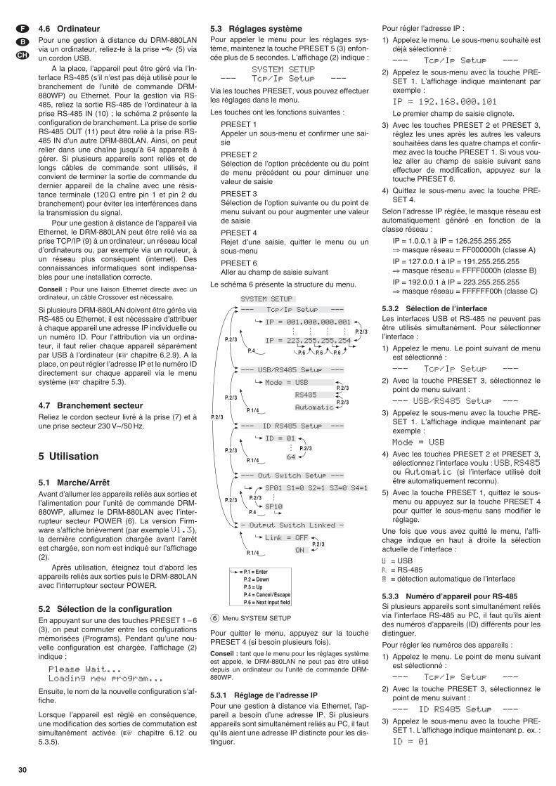
4.6 OrdinateurPour une gestion à distance du DRM-880LANvia un ordinateur, reliez-le à la prise (5) viaun cordon USB.
A la place, lʼappareil peut être géré via lʼin-terface RS-485 (sʼil nʼest pas déjà utilisé pour lebranchement de lʼunité de commande DRM-880WP) ou Ethernet. Pour la gestion via RS-485, reliez la sortie RS-485 de lʼordinateur à laprise RS-485 IN (10) ; le schéma 2 présente laconfiguration de branchement. La prise de sortieRS-485 OUT (11) peut être relié à la prise RS-485 IN dʼun autre DRM-880LAN. Ainsi, on peutrelier dans une chaîne jusquʼà 64 appareils àgérer. Si plusieurs appareils sont reliés et delongs câbles de commande sont utilisés, ilconvient de terminer la sortie de commande dudernier appareil de la chaîne avec une résis-tance terminale (120 Ω entre pin 1 et pin 2 dubranchement) pour éviter les interférences dansla transmission du signal.
Pour une gestion à distance de lʼappareil viaEthernet, le DRM-880LAN peut être relié via saprise TCP/ IP (9) à un ordinateur, un réseau localdʼordinateurs ou, par exemple via un routeur, àun réseau plus conséquent (internet). Desconnaissances informatiques sont indispensa-bles pour une installation correcte.
Conseil : Pour une liaison Ethernet directe avec unordinateur, un câble Crossover est nécessaire.
Si plusieurs DRM-880LAN doivent être gérés viaRS-485 ou Ethernet, il est nécessaire dʼattribuerà chaque appareil une adresse IP individuelle ouun numéro ID. Pour lʼattribution via un ordina-teur, il faut relier chaque appareil séparémentpar USB à lʼordinateur (� chapitre 6.2.9). A laplace, on peut régler lʼadresse IP et le numéro IDdirectement sur chaque appareil via le menusystème (� chapitre 5.3).
4.7 Branchement secteurReliez le cordon secteur livré à la prise (7) et àune prise secteur 230 V~/ 50 Hz.
5 Utilisation
5.1 Marche/ ArrêtAvant dʼallumer les appareils reliés aux sorties etlʼalimentation pour lʼunité de commande DRM-880WP, allumez le DRM-880LAN avec lʼinter-rupteur secteur POWER (6). La version Firm-ware sʼaffiche brièvement (par exemple V1.3),la dernière configuration chargée avant lʼarrêtest chargée, son nom est indiqué sur lʼaffichage(2).
Après utilisation, éteignez tout dʻabord lesappareils reliés aux sorties puis le DRM-880LANavec lʼinterrupteur secteur POWER.
5.2 Sélection de la configurationEn appuyant sur une des touches PRESET 1 – 6(3), on peut commuter entre les configurationsmémorisées (Programs). Pendant quʼune nou-velle configuration est chargée, lʼaffichage (2)indique :
Please Wait...Loading new program...
Ensuite, le nom de la nouvelle configuration sʼaf-fiche.
Lorsque lʼappareil est réglé en conséquence,une modification des sorties de commutation estsimultanément activée (� chapitre 6.12 ou5.3.5).
5.3 Réglages systèmePour appeler le menu pour les réglages sys-tème, maintenez la touche PRESET 5 (3) enfon-cée plus de 5 secondes. Lʼaffichage (2) indique :
SYSTEM SETUP--- Tcp/Ip Setup ---
Via les touches PRESET, vous pouvez effectuerles réglages dans le menu.
Les touches ont les fonctions suivantes :
PRESET 1Appeler un sous-menu et confirmer une sai-sie
PRESET 2Sélection de lʼoption précédente ou du pointde menu précédent ou pour diminuer unevaleur de saisie
PRESET 3Sélection de lʼoption suivante ou du point demenu suivant ou pour augmenter une valeurde saisie
PRESET 4Rejet dʼune saisie, quitter le menu ou unsous-menu
PRESET 6Aller au champ de saisie suivant
Le schéma 6 présente la structure du menu.
Pour quitter le menu, appuyez sur la touchePRESET 4 (si besoin plusieurs fois).
Conseil : tant que le menu pour les réglages systèmeest appelé, le DRM-880LAN ne peut pas être utilisédepuis un ordinateur ou lʼunité de commande DRM-880WP.
5.3.1 Réglage de lʼadresse IPPour une gestion à distance via Ethernet, lʼap-pareil a besoin dʼune adresse IP. Si plusieursappareils sont simultanément reliés au PC, il fautquʼils aient une adresse IP distincte pour les dis-tinguer.
Pour régler lʼadresse IP :
1) Appelez le menu. Le sous-menu souhaité estdéjà sélectionné :
--- Tcp/Ip Setup ---
2) Appelez le sous-menu avec la touche PRE-SET 1. Lʼaffichage indique maintenant parexemple :
IP = 192.168.000.101
Le premier champ de saisie clignote.
3) Avec les touches PRESET 2 et PRESET 3,réglez les unes après les autres les valeurssouhaitées dans les quatre champs et confir-mez avec la touche PRESET 1. Si vous vou-lez aller au champ de saisie suivant sanseffectuer de modification, appuyez sur latouche PRESET 6.
4) Quittez le sous-menu avec la touche PRE-SET 4.
Selon lʼadresse IP réglée, le masque réseau estautomatiquement généré en fonction de laclasse réseau :
IP = 1.0.0.1 à IP = 126.255.255.255⇒ masque réseau = FF000000h (classe A)
IP = 127.0.0.1 à IP = 191.255.255.255⇒ masque réseau = FFFF0000h (classe B)
IP = 192.0.0.1 à IP = 223.255.255.255⇒ masque réseau = FFFFFF00h (classe C)
5.3.2 Sélection de lʼinterfaceLes interfaces USB et RS-485 ne peuvent pasêtre utilisés simultanément. Pour sélectionnerlʼinterface :
1) Appelez le menu. Le point suivant de menuest sélectionné :
--- Tcp/Ip Setup ---
2) Avec la touche PRESET 3, sélectionnez lepoint de menu suivant :
--- USB/RS485 Setup ---
3) Appelez le sous-menu avec la touche PRE-SET 1. Lʼaffichage indique maintenant parexemple :
Mode = USB
4) Avec les touches PRESET 2 et PRESET 3,sélectionnez lʼinterface voulu : USB, RS485ou Automatic (si lʼinterface utilisé doitêtre automatiquement reconnu).
5) Avec la touche PRESET 1, quittez le sous-menu ou appuyez sur la touche PRESET 4pour quitter le sous-menu sans modifier leréglage.
Une fois que vous avez quitté le menu, lʼaffi-chage indique en haut à droite la sélectionactuelle de lʼinterface :
= USB= RS-485= détection automatique de lʼinterface
5.3.3 Numéro dʼappareil pour RS-485Si plusieurs appareils sont simultanément reliésvia lʼinterface RS-485 au PC, il faut quʼils aientdes numéros dʼappareils (ID) différents pour lesdistinguer.
Pour régler les numéros des appareils :
1) Appelez le menu. Le point de menu suivantest sélectionné :
--- Tcp/Ip Setup ---
2) Avec la touche PRESET 3, sélectionnez lepoint de menu suivant :
--- ID RS485 Setup ---
3) Appelez le sous-menu avec la touche PRE-SET 1. Lʼaffichage indique maintenant p. ex. :
ID = 01
⑥ Menu SYSTEM SETUP
30
F
B
CH
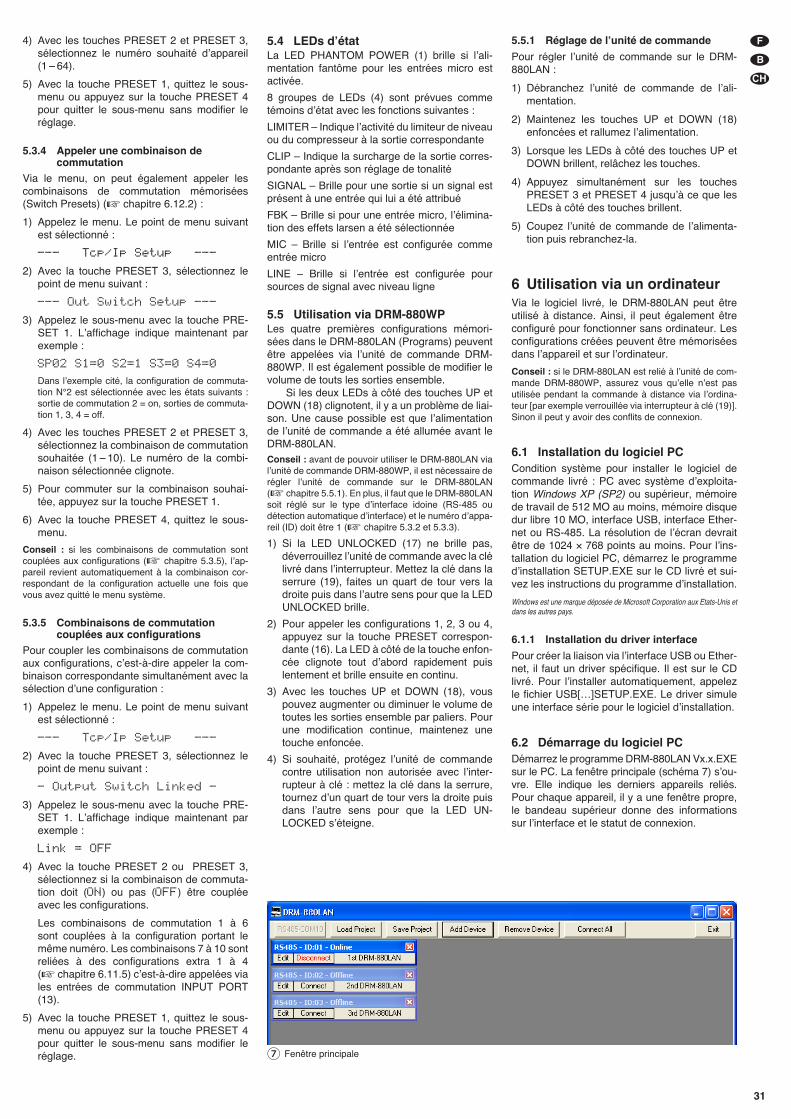
31
F
B
CH
4) Avec les touches PRESET 2 et PRESET 3,sélectionnez le numéro souhaité dʼappareil(1 – 64).
5) Avec la touche PRESET 1, quittez le sous-menu ou appuyez sur la touche PRESET 4pour quitter le sous-menu sans modifier leréglage.
5.3.4 Appeler une combinaison decommutation
Via le menu, on peut également appeler lescombinaisons de commutation mémorisées(Switch Presets) (� chapitre 6.12.2) :
1) Appelez le menu. Le point de menu suivantest sélectionné :
--- Tcp/Ip Setup ---
2) Avec la touche PRESET 3, sélectionnez lepoint de menu suivant :
--- Out Switch Setup ---
3) Appelez le sous-menu avec la touche PRE-SET 1. Lʼaffichage indique maintenant parexemple :
SP02 S1=0 S2=1 S3=0 S4=0
Dans lʼexemple cité, la configuration de commuta-tion N°2 est sélectionnée avec les états suivants :sortie de commutation 2 = on, sorties de commuta-tion 1, 3, 4 = off.
4) Avec les touches PRESET 2 et PRESET 3,sélectionnez la combinaison de commutationsouhaitée (1 – 10). Le numéro de la combi-naison sélectionnée clignote.
5) Pour commuter sur la combinaison souhai-tée, appuyez sur la touche PRESET 1.
6) Avec la touche PRESET 4, quittez le sous-menu.
Conseil : si les combinaisons de commutation sontcouplées aux configurations (� chapitre 5.3.5), lʼap-pareil revient automatiquement à la combinaison cor-respondant de la configuration actuelle une fois quevous avez quitté le menu système.
5.3.5 Combinaisons de commutationcouplées aux configurations
Pour coupler les combinaisons de commutationaux configurations, cʼest-à-dire appeler la com-binaison correspondante simultanément avec lasélection dʼune configuration :
1) Appelez le menu. Le point de menu suivantest sélectionné :
--- Tcp/Ip Setup ---
2) Avec la touche PRESET 3, sélectionnez lepoint de menu suivant :
- Output Switch Linked -
3) Appelez le sous-menu avec la touche PRE-SET 1. Lʼaffichage indique maintenant parexemple :
Link = OFF
4) Avec la touche PRESET 2 ou PRESET 3,sélectionnez si la combinaison de commuta-tion doit (ON) ou pas (OFF) être coupléeavec les configurations.
Les combinaisons de commutation 1 à 6 sont couplées à la configuration portant lemême numéro. Les combinaisons 7 à 10 sontreliées à des configurations extra 1 à 4(� chapitre 6.11.5) cʼest-à-dire appelées viales entrées de commutation INPUT PORT(13).
5) Avec la touche PRESET 1, quittez le sous-menu ou appuyez sur la touche PRESET 4pour quitter le sous-menu sans modifier leréglage.
5.4 LEDs dʼétatLa LED PHANTOM POWER (1) brille si lʼali-mentation fantôme pour les entrées micro estactivée.
8 groupes de LEDs (4) sont prévues commetémoins dʼétat avec les fonctions suivantes :
LIMITER – Indique lʼactivité du limiteur de niveauou du compresseur à la sortie correspondante
CLIP – Indique la surcharge de la sortie corres-pondante après son réglage de tonalité
SIGNAL – Brille pour une sortie si un signal estprésent à une entrée qui lui a été attribué
FBK – Brille si pour une entrée micro, lʼélimina-tion des effets larsen a été sélectionnée
MIC – Brille si lʼentrée est configurée commeentrée micro
LINE – Brille si lʼentrée est configurée poursources de signal avec niveau ligne
5.5 Utilisation via DRM-880WPLes quatre premières configurations mémori-sées dans le DRM-880LAN (Programs) peuventêtre appelées via lʼunité de commande DRM-880WP. Il est également possible de modifier levolume de touts les sorties ensemble.
Si les deux LEDs à côté des touches UP etDOWN (18) clignotent, il y a un problème de liai-son. Une cause possible est que lʼalimentationde lʼunité de commande a été allumée avant leDRM-880LAN.Conseil : avant de pouvoir utiliser le DRM-880LAN vialʼunité de commande DRM-880WP, il est nécessaire derégler lʼunité de commande sur le DRM-880LAN(� chapitre 5.5.1). En plus, il faut que le DRM-880LANsoit réglé sur le type dʼinterface idoine (RS-485 oudétection automatique dʼinterface) et le numéro dʼappa-reil (ID) doit être 1 (� chapitre 5.3.2 et 5.3.3).
1) Si la LED UNLOCKED (17) ne brille pas,déverrouillez lʼunité de commande avec la clélivré dans lʼinterrupteur. Mettez la clé dans laserrure (19), faites un quart de tour vers ladroite puis dans lʼautre sens pour que la LEDUNLOCKED brille.
2) Pour appeler les configurations 1, 2, 3 ou 4,appuyez sur la touche PRESET correspon-dante (16). La LED à côté de la touche enfon-cée clignote tout dʼabord rapidement puislentement et brille ensuite en continu.
3) Avec les touches UP et DOWN (18), vouspouvez augmenter ou diminuer le volume detoutes les sorties ensemble par paliers. Pourune modification continue, maintenez unetouche enfoncée.
4) Si souhaité, protégez lʼunité de commandecontre utilisation non autorisée avec lʼinter-rupteur à clé : mettez la clé dans la serrure,tournez dʼun quart de tour vers la droite puisdans lʼautre sens pour que la LED UN -LOCKED sʼéteigne.
5.5.1 Réglage de lʼunité de commande
Pour régler lʼunité de commande sur le DRM-880LAN :
1) Débranchez lʼunité de commande de lʼali-mentation.
2) Maintenez les touches UP et DOWN (18)enfoncées et rallumez lʼalimentation.
3) Lorsque les LEDs à côté des touches UP etDOWN brillent, relâchez les touches.
4) Appuyez simultanément sur les touchesPRESET 3 et PRESET 4 jusquʼà ce que lesLEDs à côté des touches brillent.
5) Coupez lʼunité de commande de lʼalimenta-tion puis rebranchez-la.
6 Utilisation via un ordinateurVia le logiciel livré, le DRM-880LAN peut être utilisé à distance. Ainsi, il peut également êtreconfiguré pour fonctionner sans ordinateur. Lesconfigurations créées peuvent être mémoriséesdans lʼappareil et sur lʼordinateur.
Conseil : si le DRM-880LAN est relié à lʼunité de com-mande DRM-880WP, assurez vous quʼelle nʼest pasutilisée pendant la commande à distance via lʼordina-teur [par exemple verrouillée via interrupteur à clé (19)].Sinon il peut y avoir des conflits de connexion.
6.1 Installation du logiciel PCCondition système pour installer le logiciel decommande livré : PC avec système dʼexploita-tion Windows XP (SP2) ou supérieur, mémoirede travail de 512 MO au moins, mémoire disquedur libre 10 MO, interface USB, interface Ether-net ou RS-485. La résolution de lʼécran devraitêtre de 1024 × 768 points au moins. Pour lʼins-tallation du logiciel PC, démarrez le programmedʼinstallation SETUP.EXE sur le CD livré et sui-vez les instructions du programme dʼinstallation.
Windows est une marque déposée de Microsoft Corporation aux Etats-Unis etdans les autres pays.
6.1.1 Installation du driver interface
Pour créer la liaison via lʼinterface USB ou Ether-net, il faut un driver spécifique. Il est sur le CDlivré. Pour lʼinstaller automatiquement, appelezle fichier USB[…]SETUP.EXE. Le driver simuleune interface série pour le logiciel dʼinstallation.
6.2 Démarrage du logiciel PCDémarrez le programme DRM-880LAN Vx.x.EXEsur le PC. La fenêtre principale (schéma 7) sʼou-vre. Elle indique les derniers appareils reliés.Pour chaque appareil, il y a une fenêtre propre,le bandeau supérieur donne des informationssur lʼinterface et le statut de connexion.
⑦ Fenêtre principale
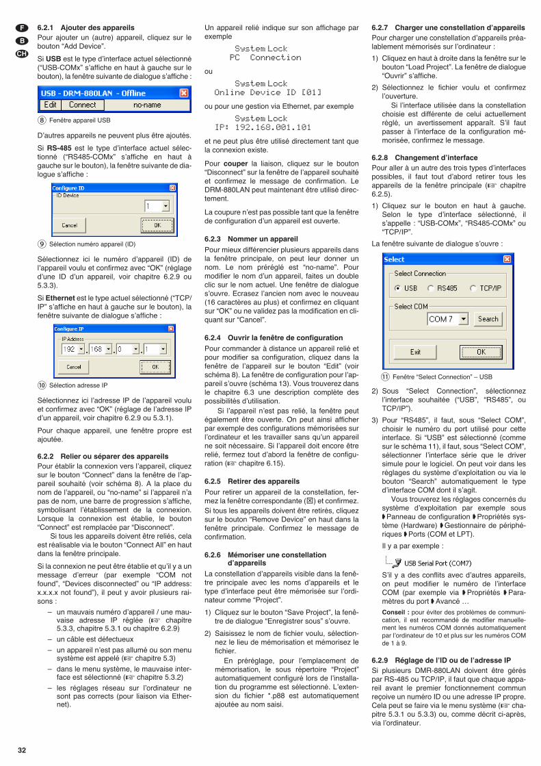
6.2.1 Ajouter des appareilsPour ajouter un (autre) appareil, cliquez sur lebouton “Add Device”.
Si USB est le type dʼinterface actuel sélectionné(“USB-COMx” sʼaffiche en haut à gauche sur lebouton), la fenêtre suivante de dialogue sʼaffiche :
Dʼautres appareils ne peuvent plus être ajoutés.
Si RS-485 est le type dʼinterface actuel sélec-tionné (“RS485-COMx” sʼaffiche en haut àgauche sur le bouton), la fenêtre suivante de dia-logue sʼaffiche :
Sélectionnez ici le numéro dʼappareil (ID) delʼappareil voulu et confirmez avec “OK” (réglagedʼune ID dʼun appareil, voir chapitre 6.2.9 ou5.3.3).
Si Ethernet est le type actuel sélectionné (“TCP/IP” sʼaffiche en haut à gauche sur le bouton), lafenêtre suivante de dialogue sʼaffiche :
Sélectionnez ici lʼadresse IP de lʼappareil vouluet confirmez avec “OK” (réglage de lʼadresse IPdʼun appareil, voir chapitre 6.2.9 ou 5.3.1).
Pour chaque appareil, une fenêtre propre estajoutée.
6.2.2 Relier ou séparer des appareilsPour établir la connexion vers lʼappareil, cliquezsur le bouton “Connect” dans la fenêtre de lʼap-pareil souhaité (voir schéma 8). A la place dunom de lʼappareil, ou “no-name” si lʼappareil nʼapas de nom, une barre de progression sʼaffiche,symbolisant lʼétablissement de la connexion.Lorsque la connexion est établie, le bouton“Connect” est remplacée par “Disconnect”.
Si tous les appareils doivent être reliés, celaest réalisable via le bouton “Connect All” en hautdans la fenêtre principale.
Si la connexion ne peut être établie et quʼil y a unmessage dʼerreur (par exemple “COM notfound”, “Devices disconnected” ou “IP address:x.x.x.x not found”), il peut y avoir plusieurs rai-sons :
– un mauvais numéro dʼappareil / une mau-vaise adresse IP réglée (� chapitre5.3.3, chapitre 5.3.1 ou chapitre 6.2.9)
– un câble est défectueux
– un appareil nʼest pas allumé ou son menusystème est appelé (� chapitre 5.3)
– dans le menu système, le mauvaise inter-face est sélectionné (� chapitre 5.3.2)
– les réglages réseau sur lʼordinateur nesont pas corrects (pour liaison via Ether-net).
Un appareil relié indique sur son affichage parexemple
System LockPC Connection
ou
System LockOnline Device ID [01]
ou pour une gestion via Ethernet, par exemple
System LockIP: 192.168.001.101
et ne peut plus être utilisé directement tant quela connexion existe.
Pour couper la liaison, cliquez sur le bouton“Disconnect” sur la fenêtre de lʼappareil souhaitéet confirmez le message de confirmation. LeDRM-880LAN peut maintenant être utilisé direc-tement.
La coupure nʼest pas possible tant que la fenêtrede configuration dʼun appareil est ouverte.
6.2.3 Nommer un appareilPour mieux différencier plusieurs appareils dansla fenêtre principale, on peut leur donner unnom. Le nom préréglé est “no-name”. Pourmodifier le nom dʼun appareil, faites un doubleclic sur le nom actuel. Une fenêtre de dialoguesʼouvre. Ecrasez lʼancien nom avec le nouveau(16 caractères au plus) et confirmez en cliquantsur “OK” ou ne validez pas la modification en cli-quant sur “Cancel”.
6.2.4 Ouvrir la fenêtre de configurationPour commander à distance un appareil relié etpour modifier sa configuration, cliquez dans lafenêtre de lʼappareil sur le bouton “Edit” (voirschéma 8). La fenêtre de configuration pour lʼap-pareil sʼouvre (schéma 13). Vous trouverez dansle chapitre 6.3 une description complète despossibilités dʼutilisation.
Si lʼappareil nʼest pas relié, la fenêtre peutégalement être ouverte. On peut ainsi afficherpar exemple des configurations mémorisées surlʼordinateur et les travailler sans quʼun appareilne soit nécessaire. Si lʼappareil doit encore êtrerelié, fermez tout dʼabord la fenêtre de configu-ration (� chapitre 6.15).
6.2.5 Retirer des appareilsPour retirer un appareil de la constellation, fer-mez la fenêtre correspondante (⊠) et confirmez.Si tous les appareils doivent être retirés, cliquezsur le bouton “Remove Device” en haut dans lafenêtre principale. Confirmez le message deconfirmation.
6.2.6 Mémoriser une constellationdʼappareils
La constellation dʼappareils visible dans la fenê-tre principale avec les noms dʼappareils et letype dʼinterface peut être mémorisée sur lʼordi-nateur comme “Project”.
1) Cliquez sur le bouton “Save Project”, la fenê-tre de dialogue “Enregistrer sous” sʼouvre.
2) Saisissez le nom de fichier voulu, sélection-nez le lieu de mémorisation et mémorisez lefichier.
En préréglage, pour lʼemplacement demémorisation, le sous répertoire “Project”automatiquement configuré lors de lʼinstalla-tion du programme est sélectionné. Lʼexten-sion du fichier *.p88 est automatiquementajoutée au nom saisi.
6.2.7 Charger une constellation dʼappareilsPour charger une constellation dʼappareils préa-lablement mémorisés sur lʼordinateur :
1) Cliquez en haut à droite dans la fenêtre sur lebouton “Load Project”. La fenêtre de dialogue“Ouvrir” sʼaffiche.
2) Sélectionnez le fichier voulu et confirmezlʼouverture.
Si lʼinterface utilisée dans la constellationchoisie est différente de celui actuellementréglé, un avertissement apparaît. Sʼil fautpasser à lʼinterface de la configuration mé -morisée, confirmez le message.
6.2.8 Changement dʼinterfacePour aller à un autre des trois types dʼinterfacespossibles, il faut tout dʼabord retirer tous lesappareils de la fenêtre principale (� chapitre6.2.5).
1) Cliquez sur le bouton en haut à gauche.Selon le type dʼinterface sélectionné, il sʼappelle : “USB-COMx”, “RS485-COMx” ou“TCP/ IP”.
La fenêtre suivante de dialogue sʼouvre :
2) Sous “Select Connection”, sélectionnez lʼinterface souhaitée (“USB”, “RS485”, ouTCP/ IP”).
3) Pour “RS485”, il faut, sous “Select COM”,choisir le numéro du port utilisé pour cetteinterface. Si “USB” est sélectionné (commesur le schéma 11), il faut, sous “Select COM”,sélectionner lʼinterface série que le driversimule pour le logiciel. On peut voir dans lesréglages du système dʼexploitation ou via lebouton “Search” automatiquement le typedʼinterface COM dont il sʼagit.
Vous trouverez les réglages concernés dusystème dʼexploitation par exemple sous�Panneau de configuration �Propriétés sys-tème (Hardware) �Gestionnaire de périphé-riques �Ports (COM et LPT).
Il y a par exemple :
Sʼil y a des conflits avec dʼautres appareils,on peut modifier le numéro de lʼinterfaceCOM (par exemple via �Propriétés �Para-mètres du port �Avancé …
Conseil : pour éviter des problèmes de communi-cation, il est recommandé de modifier manuelle-ment les numéros COM donnés automatiquementpar lʼordinateur de 10 et plus sur les numéros COMde 1 à 9.
6.2.9 Réglage de lʼID ou de lʼadresse IPSi plusieurs DMR-880LAN doivent être géréspar RS-485 ou TCP/IP, il faut que chaque appa-reil avant le premier fonctionnement communreçoive un numéro ID ou une adresse IP propre.Cela peut se faire via le menu système (� cha-pitre 5.3.1 ou 5.3.3) ou, comme décrit ci-après,via lʼordinateur.
⑪ Fenêtre “Select Connection” – USB
⑩ Sélection adresse IP
⑨ Sélection numéro appareil (ID)
⑧ Fenêtre appareil USB
32
F
B
CH
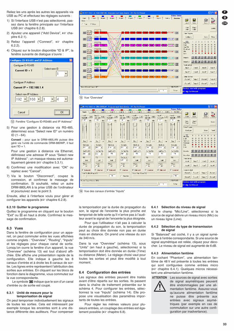
33
F
B
CH
Reliez les uns après les autres les appareils viaUSB au PC et effectuez les réglages suivants :
1) Si lʼinterface USB nʼest pas sélectionné, pas-sez dans la fenêtre principale sur lʼinterfaceUSB (� chapitre 6.2.8).
2) Ajoutez une appareil (“Add Device”, � cha-pitre 6.2.1).
3) Reliez lʼappareil (“Connect”, � chapitre6.2.2).
4) Cliquez sur le bouton disponible “ID & IP”, lafenêtre suivante de dialogue sʼouvre :
5) Pour une gestion à distance via RS-485,déterminez sous “Select new ID” un numéroID (1 – 64).Conseil : pour que le DRM-480LAN puisse êtregéré via lʼunité de commande DRM-880WP, il fautque lʼID = 1.
Pour une gestion à distance via Ethernet,définissez une adresse IP sous “Select newIP Address” ; un masque réseau est automa-tiquement généré (� chapitre 5.3.1).
6) Confirmez une modification avec “OK” ourejetez avec “Cancel”.
7) Via le bouton “Disconnect”, coupez laconnexion, et confirmez le message deconfirmation. Si souhaité, reliez un autreDRM-880LAN à la prise USB de lʼordinateuret poursuivez avec le point 3.
Ensuite, allez à lʼinterface voulu pour gérer etconfigurer les appareils (� chapitre 6.2.8).
6.2.10 Quitter le programmeQuittez le programme en cliquant sur le bouton“Exit” ou ⊠ en haut à droite. Confirmez le mes-sage de confirmation.
6.3 VuesDans la fenêtre de configuration pour un appa-reil, on peut commuter entre les vues affichéescomme onglets : “Overview”, “Routing”, “Inputs”et les réglages pour chaque canal de sortie.Lorsquʼon ouvre la fenêtre dʼun appareil, la vue“Overview” (schéma 13) est tout dʼabord affi-chée. Elle affiche une présentation rapide de laconfiguration. Elle indique à gauche les 8canaux dʼentrée et à droite les 8 canaux de sor-tie. Les lignes entre représentent lʼattribution dessorties aux entrées. En cliquant sur les blocs defonction dans le diagramme, vous commutez surla vue correspondante.
Le symbole indique que le son dʼun canaldʼentrée ou de sortie est coupé.
6.3.1 Unité de mesure pour latemporisation de signal
On peut temporiser individuellement les signauxde toutes les sorties. Cela est intéressant parexemple lorsque les enceintes sont à une dis-tance différente des auditeurs. Pour compenser
⑫ Fenêtre “Configure ID-RS485 and IP Address”
la temporisation par la durée de propagation duson, le signal de lʼenceinte la plus proche esttemporisé de telle sorte quʼil nʼarrive pas à lʼaudi-teur avant le signal de lʼenceinte la plus éloignée.
Pour que lʼutilisateur nʼait pas à calculer ladurée de propagation du son, la temporisationpeut au choix être donnée non pas en duréemais en distance. On prend une vitesse du sonde 340 m/s.
Dans la vue “Overview” (schéma 13), sous“Units” (en haut à gauche), sélectionnez si latemporisation doit être donnée en durée (Time)ou distance (Meter). Le réglage choisi vaut pourtoutes les sorties et peut être modifié à toutmoment.
6.4 Configuration des entréesLes signaux des entrées peuvent être traitésavant dʼêtre répartis sur les sorties. Ils passentdans la chaîne de traitement présentée sur leschéma 4. Pour configurer les entrées, sélec-tionnez la vue “Inputs” (schéma 14). Elle pro-pose une visualisation des paramètres impor-tants de toutes les entrées.
Pour régler les mêmes valeurs pour plu-sieurs entrées, un couplage des entrées est éga-lement possible (� chapitre 6.8).
6.4.1 Sélection du niveau de signalVia le champ “Mic/ Line”, sélectionnez si lasource de signal délivre un niveau micro (Mic) ouun niveau ligne (Line).
6.4.2 Sélection du type de transmission de signal
Si “Balanced” est coché, il y a un signal symé-trique à lʼentrée correspondante. Si une source designal asymétrique est reliée, cliquez pour déco-cher. Le niveau de signal est augmenté de 6 dB.
6.4.3 Alimentation fantômeEn cochant “Phantom”, une alimentation fan-tôme de 48 V est présente à toutes les entréesqui sont configurées comme entrées micro(� chapitre 6.4.1). Quelques micros nécessi-tent une alimentation fantôme.
ATTENTION Les sources de signal avec sortiesde signal asymétriques peuventêtre endommagées par une ali-mentation fantôme. Assurez-vousquʼaucune alimentation fantômene puisse être présente auxentrées avec signaux asymé-triques (par exemple en cas decommutation sur une autre confi-guration par inadvertance).
⑭ Vue des canaux dʼentrée “Inputs”
⑬ Vue “Overview”
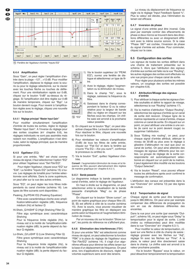
34
F
B
CH
Le niveau du déplacement de fréquence serègle via le réglage “Input Feedback Speed %”.Plus la valeur est élevée, plus lʼélimination dularsen est efficace.
6.4.7 Inversion de phaseLe signal dʼune entrée peut être inversé. Celapeut par exemple contrer des effacements dephase si deux micros se trouvent dans des direc-tions différentes ou avec un éloignement diffé-rent avec la même source sonore. Si la case“Phase 180°” est cochée, lʼinversion de phasedu signal dʼentrée est activée. Pour commuter,cliquez sur la case.
6.5 Configuration des sortiesLes signaux de toutes les sorties défilent dansune chaîne de traitement présentée sur leschéma 5. Alors que lʼattribution des signauxdʼentrée aux sorties est faite via la vue “Routing”,les autres réglages des sorties sont effectués viaune vue propre pour chaque canal de sortie.
Pour régler pour plusieurs sorties les mêmesvaleurs, un couplage des sorties est possible(� chapitre 6.8).
6.5.1 Attribution/ Mixage des signauxdʼentrée
1) Pour attribuer à chaque sortie les signaux dʼen-trée souhaités et définir le rapport de mixage,sélectionnez la vue “Routing” (schéma 17).
2) Via la matrice dʼattribution “Output Routing”,sélectionnez les signaux dʼentrée quʼun canalde sortie doit recevoir. Chaque ligne de lamatrice représente un canal dʼentrée, chaquecolonne un canal de sortie. En cliquant sur unpoint, on peut attribuer une entrée à une sor-tie (le carré sur le point devient rouge) ousupprimer lʼattribution.
3) Sous “Editing mix routing”, on peut, pourchaque signal dʼentrée attribué, atténuer leniveau de 30 dB au plus avec le réglage àglissière (lʼatténuation ne vaut que pour cecanal de sortie). On peut ainsi atteindre desmixages de signaux différents pour les sor-ties. Le groupe de réglage de la sortie cor-respondante est automatiquement sélec-tionné en cliquant sur un point de la matrice,il peut également être modifié via les boutons“Output Selected”.
4) Via le bouton “Reset”, vous pouvez effacertoutes les attributions après avoir confirmé lemessage de confirmation.
Lʼattribution des canaux est présentée dans lavue “Overview” (� schéma 13) par des lignesde couleur.
6.5.2 Temporisation de signalChaque signal de sortie peut être temporiséjusquʼà 380,998 ms. On peut ainsi par exemplecompenser des différences de propagation duson en cas de distances différentes desenceintes.
Dans la vue pour une sortie (par exemple “Out-put1”, schéma 18), on peut régler sous “Delay” latemporisation pour le signal de sortie. Lʼunité(mètre ou millisecondes) peut être modifiéedans la vue “Overview” (� chapitre 6.3.1).
Pour modifier la valeur de temporisation, cli-quez sur une flèche à côté du champ de saisie :réglage grossier avec les flèches sur “Adj”,réglage fin avec les flèches sur “Fine”. A laplace, la valeur peut être directement saisiedans le champ. Le chiffre saisi est arrondi à lavaleur prochaine possible.
Via le bouton “Bypass” sous la valeur, onpeut désactiver temporairement la temporisation
6.4.4 Amplification
Sous “Gain”, on peut régler lʼamplification dʼen-trée dans la plage -127…+12 dB. Pour modifierlʼamplification, déplacez le réglage avec la sou-ris ou pour le réglage sélectionné, sur le clavieravec les touches flèche ou touches de défile-ment. Pour une réinitialisation rapide sur 0 dB,cliquez sur le bouton “0 dB” au-dessus du ré -glage. Si lʼamplification doit être réglée sur 0 dBde manière temporaire, cliquez sur “Byp”. Lebouton devient rouge. Pour revenir à lʼamplifica-tion réglée avec le réglage, cliquez une nouvellefois sur le bouton.
6.4.4.1 Réglage principal “Master Input Gain”
Pour modifier simultanément lʼamplificationdʼentrée de toutes les sorties, réglez le réglage“Master Input Gain”. A lʼinverse du réglage pourdes sorties couplées (� chapitre 6.8), lesréglages individuels ne sont pas assimilés maisrestent non modifiés. Lʼamplification nʼest dimi-nuée, selon le réglage principal, que de manièreproportionnelle.
6.4.5 Egaliseur (EQ)
Si pour une entrée, “Mic” est choisi commeniveau de signal, il faut sélectionner lʼoption “EQ”pour utiliser lʼégaliseur sous “Sel Fbk/ EQ”.
Pour régler lʼégaliseur, cliquez sous “EQ” sur“Edit”. La fenêtre “Inputs EQ” (schéma 15) sʼou-vre. Les réglages de tonalité pour lʼentrée sélec-tionnée sont affichés. Dans la zone supérieure,on peut aller sur la vue des autres entrées.
Sous “EQ”, on peut régler les trois filtres indé-pendants du canal dʼentrée (schéma 16). Lestypes de filtre suivants sont disponibles :
Peaking_Eq / PEAK EQ (Peaking Equalizer)Filtre avec caractéristique cloche avec ampli-fication/ atténuation réglable (dB), fréquencemédium (Hz) et facteur Q
Hi-Shelv_Q / HiSHF Q (High Shelving Filter Q)Filtre aigu symétrique avec caractéristiqueShelvingPour la fréquence limite réglable (Hz), leniveau est à la moitié de lʼamplification/ atté-nuation réglée (dB); la pente dépend du fac-teur Q réglable.
Lo-Shelv_Q / LoSHF Q (Low Shelving Filter Q)Filtre grave symétrique avec caractéristiqueShelvingPour la fréquence limite réglable (Hz), leniveau est à la moitié de lʼamplification/ atté-nuation réglée (dB); la pente dépend du fac-teur Q réglable.
1) Via le bouton supérieur (ici “PEAKEQ”), ouvrez une fenêtre de dia-logue et sélectionnez un type de fil-tre.
2) Avec le réglage, réglez lʼaugmen-tation ou la diminution de niveau.
3) Dans le champ “Hz”, sous leréglage, saisissez la fréquence dufiltre.
4) Saisissez dans le champ corres-pondant le facteur Q ou la valeurrelative pour la largeur de bande(Bw) ou réglez en cliquant sur lesflèches sous les champs. Un chif-fre saisi est arrondi à la prochainevaleur possible.
5) En cliquant sur le bouton “Byp”, on peut dés-activer chaque filtre. Le bouton devient rouge.Pour réactiver le filtre, cliquez une nouvellefois sur le bouton.
6) Pour réinitialiser les valeurs dʼamplification(0 dB) de tous les filtres de cette entrée, cliquez sur “Flat Eq” et dans la fenêtre quisʼouvre “Fla EQ – Are you sure?”, confirmezle processus ou arrêtez-le.
7) Via le bouton “Exit”, quittez lʼégaliseur dʼen-trée.
Conseil : lʼaugmentation/ diminution de niveau et la fré-quence de filtre peuvent alternativement être régléesde manière graphique (� chapitre 6.4.5.1).
6.4.5.1 Bande passanteLe diagramme indique la bande passante ducanal dʼentrée, selon le réglage de lʼégaliseur.
En haut à droite sur le diagramme, on peutsélectionner entre la visualisation de la bandepassante dʼamplitude “Mag” ou de phase“Phase”.
En cliquant sur le bouton “Show cursor”, unpoint de repère graphique pour chaque filtre ( ,
, ) est affiché à côté de la courbe (schéma15). Avec la souris, vous pouvez visualiser demanière graphique les filtre en déplaçant cespoints selon la fréquence et lʼaugmentation/ dimi-nution de niveau.
Par un nouveau clic sur le bouton “Show cur-sor”, les points de référence ne sʼaffichent plus.
6.4.6 Elimination des interférences (FBK)
Si pour une entrée “Mic” est sélectionné commeniveau de signal, on peut sélectionner la fonction“FBK” à la place du réglage de lʼégaliseur sous“Sel Fbk/ EQ” (schéma 14). Il sʼagit dʼun algo-rithme efficace pour éliminer les effets larsen surla base dʼun déplacement de fréquence. On peutainsi, lors dʼapplications de discours, régler desvolumes supérieurs sans avoir des larsens.
⑯ “EQ”
⑮ Fenêtre de lʼégaliseur dʼentrée “Inputs EQ”
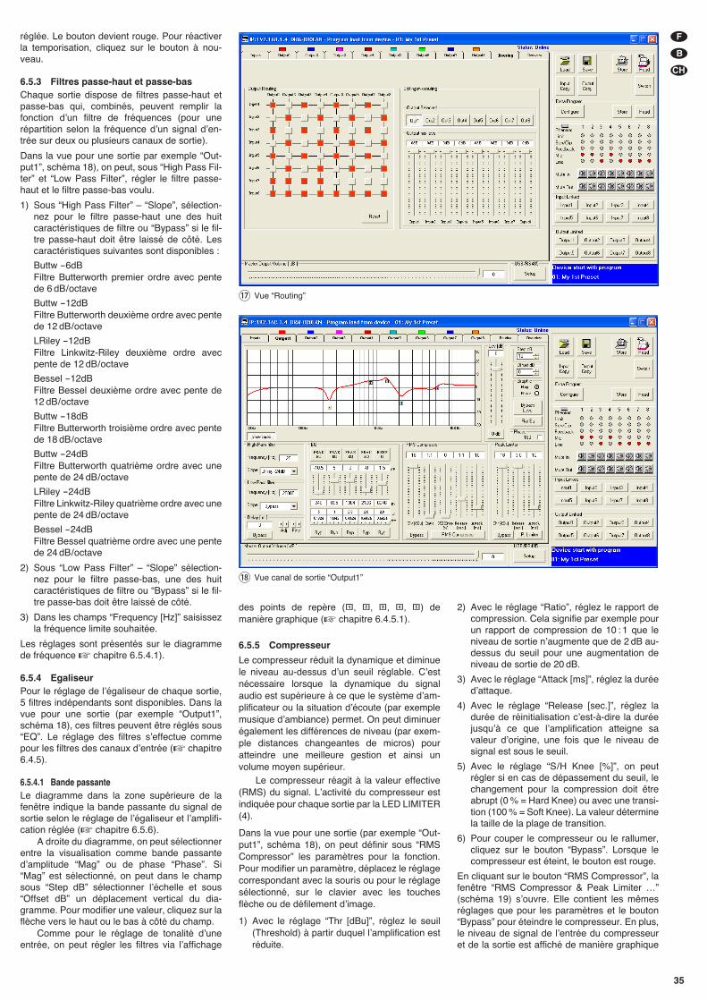
35
F
B
CH
réglée. Le bouton devient rouge. Pour réactiverla temporisation, cliquez sur le bouton à nou-veau.
6.5.3 Filtres passe-haut et passe-basChaque sortie dispose de filtres passe-haut etpasse-bas qui, combinés, peuvent remplir lafonction dʼun filtre de fréquences (pour unerépartition selon la fréquence dʼun signal dʼen-trée sur deux ou plusieurs canaux de sortie).
Dans la vue pour une sortie par exemple “Out-put1”, schéma 18), on peut, sous “High Pass Fil-ter” et “Low Pass Filter”, régler le filtre passe-haut et le filtre passe-bas voulu.
1) Sous “High Pass Filter” – “Slope”, sélection-nez pour le filtre passe-haut une des huitcaractéristiques de filtre ou “Bypass” si le fil-tre passe-haut doit être laissé de côté. Lescaractéristiques suivantes sont disponibles :
Buttw -6dBFiltre Butterworth premier ordre avec pentede 6 dB / octave
Buttw -12dBFiltre Butterworth deuxième ordre avec pentede 12 dB / octave
LRiley -12dBFiltre Linkwitz-Riley deuxième ordre avecpente de 12 dB / octave
Bessel -12dBFiltre Bessel deuxième ordre avec pente de12 dB / octave
Buttw -18dBFiltre Butterworth troisième ordre avec pentede 18 dB / octave
Buttw -24dBFiltre Butterworth quatrième ordre avec unepente de 24 dB / octave
LRiley -24dBFiltre Linkwitz-Riley quatrième ordre avec unepente de 24 dB / octave
Bessel -24dBFiltre Bessel quatrième ordre avec une pentede 24 dB / octave
2) Sous “Low Pass Filter” – “Slope” sélection-nez pour le filtre passe-bas, une des huitcaractéristiques de filtre ou “Bypass” si le fil-tre passe-bas doit être laissé de côté.
3) Dans les champs “Frequency [Hz]” saisissezla fréquence limite souhaitée.
Les réglages sont présentés sur le diagrammede fréquence � chapitre 6.5.4.1).
6.5.4 EgaliseurPour le réglage de lʼégaliseur de chaque sortie,5 filtres indépendants sont disponibles. Dans lavue pour une sortie (par exemple “Output1”,schéma 18), ces filtres peuvent être réglés sous“EQ”. Le réglage des filtres sʼeffectue commepour les filtres des canaux dʼentrée (� chapitre6.4.5).
6.5.4.1 Bande passanteLe diagramme dans la zone supérieure de lafenêtre indique la bande passante du signal desortie selon le réglage de lʼégaliseur et lʼamplifi-cation réglée (� chapitre 6.5.6).
A droite du diagramme, on peut sélectionnerentre la visualisation comme bande passantedʼamplitude “Mag” ou de phase “Phase”. Si“Mag” est sélectionné, on peut dans le champsous “Step dB” sélectionner lʼéchelle et sous“Offset dB” un déplacement vertical du dia-gramme. Pour modifier une valeur, cliquez sur laflèche vers le haut ou le bas à côté du champ.
Comme pour le réglage de tonalité dʼuneentrée, on peut régler les filtres via lʼaffichage
des points de repère ( , , , , ) demanière graphique (� chapitre 6.4.5.1).
6.5.5 Compresseur
Le compresseur réduit la dynamique et diminuele niveau au-dessus dʼun seuil réglable. Cʼestnécessaire lorsque la dynamique du signalaudio est supérieure à ce que le système dʼam-plificateur ou la situation dʼécoute (par exemplemusique dʼambiance) permet. On peut diminuerégalement les différences de niveau (par exem-ple distances changeantes de micros) pouratteindre une meilleure gestion et ainsi unvolume moyen supérieur.
Le compresseur réagit à la valeur effective(RMS) du signal. Lʼactivité du compresseur estindiquée pour chaque sortie par la LED LIMITER(4).
Dans la vue pour une sortie (par exemple “Out-put1”, schéma 18), on peut définir sous “RMSCompressor” les paramètres pour la fonction.Pour modifier un paramètre, déplacez le réglagecorrespondant avec la souris ou pour le réglagesélectionné, sur le clavier avec les touchesflèche ou de défilement dʼimage.
1) Avec le réglage “Thr [dBu]”, réglez le seuil(Threshold) à partir duquel lʼamplification estréduite.
2) Avec le réglage “Ratio”, réglez le rapport decompression. Cela signifie par exemple pourun rapport de compression de 10 : 1 que leniveau de sortie nʼaugmente que de 2 dB au-dessus du seuil pour une augmentation deniveau de sortie de 20 dB.
3) Avec le réglage “Attack [ms]”, réglez la duréedʼattaque.
4) Avec le réglage “Release [sec.]”, réglez ladurée de réinitialisation cʼest-à-dire la duréejusquʼà ce que lʼamplification atteigne savaleur dʼorigine, une fois que le niveau designal est sous le seuil.
5) Avec le réglage “S/ H Knee [%]”, on peutrégler si en cas de dépassement du seuil, lechangement pour la compression doit êtreabrupt (0 % = Hard Knee) ou avec une transi-tion (100 % = Soft Knee). La valeur déterminela taille de la plage de transition.
6) Pour couper le compresseur ou le rallumer,cliquez sur le bouton “Bypass”. Lorsque lecompresseur est éteint, le bouton est rouge.
En cliquant sur le bouton “RMS Compressor”, lafenêtre “RMS Compressor & Peak Limiter …”(schéma 19) sʼouvre. Elle contient les mêmesréglages que pour les paramètres et le bouton“Bypass” pour éteindre le compresseur. En plus,le niveau de signal de lʼentrée du compresseuret de la sortie est affiché de manière graphique
⑰ Vue “Routing”
⑱ Vue canal de sortie “Output1”
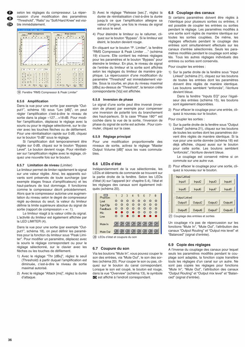
selon les réglages du compresseur. La réper-cussion dʼune modification des paramètres“Threshold”, “Ratio” ou “Soft/ Hard Knee” est visi-ble immédiatement.
6.5.6 AmplificationDans la vue pour une sortie (par exemple “Out-put1”, schéma 18) sous “Lev [dB]”, on peutrégler lʼamplification cʼest-à-dire le niveau desortie dans la plage -127…+18 dB. Pour modi-fier lʼamplification, déplacez le réglage avec lasouris ou pour le réglage sélectionné, sur le cla-vier avec les touches flèches ou de défilement.Pour une réinitialisation rapide sur 0 dB, cliquezsur le bouton “0 dB” sous le réglage.
Si lʼamplification doit temporairement êtreréglée sur 0 dB, cliquez sur le bouton “BypassLevel”. Le bouton devient rouge. Pour réinitiali-ser sur lʼamplification réglée avec le réglage, cli-quez une nouvelle fois sur le bouton.
6.5.7 Limitation de niveau (Limiter)Le limiteur permet de limiter rapidement le signalsur une valeur réglée. Ainsi, les appareils sui-vants sont préservés de toute surcharge (parexemple étages finaux dʼamplificateurs) et leshaut-parleurs de tout dommage. Il fonctionnecomme le compresseur décrit précédemment.Alors que le compresseur autorise une augmen-tation du niveau selon le degré de compresseurréglé au-dessus du seuil, la valeur du limiteurdéfinie la limite supérieure absolue du signal desortie (rapport de compression = ∞ : 1).
Le limiteur réagit à la valeur crête du signal.Lʼactivité du limiteur est également affichée parla LED LIMITER (4).
Dans la vue pour une sortie (par exemple “Out-put1”, schéma 18), on peut définir les paramè-tres pour la fonction du limiteur sous “Peak Limi-ter”. Pour modifier un paramètre, déplacez avecla souris le réglage correspondant ou pour leréglage sélectionné, sur le clavier avec lesflèches ou les touches de défilement.
1) Avec le réglage “Thr [dBu]”, réglez le seuil(Threshold) à partir duquel lʼamplification estdiminuée, cʼest-à-dire le niveau de sortiemaximal autorisé.
2) Avec le réglage “Attack [ms]”, réglez la duréedʼattaque.
3) Avec le réglage “Release [sec.]”, réglez ladurée de réinitialisation cʼest-à-dire la duréejusquʼà ce que lʼamplification atteigne savaleur dʼorigine, une fois le niveau de signalest sous le seuil.
4) Pour éteindre le limiteur ou le rallumer, cli-quez sur le bouton “Bypass”. Si le limiteur estéteint, le bouton devient rouge.
En cliquant sur le bouton “P. Limiter”, la fenêtre“RMS Compressor & Peak Limiter …” (schéma19) sʼouvre. Elle contient les mêmes réglagespour les paramètres et le bouton “Bypass” pouréteindre le limiteur. En plus, le niveau de signalde lʼentrée du limiteur et la sortie sont affichésselon les réglages du limiteur de manière gra-phique. La répercussion dʼune modification duparamètre “Threshold” est immédiatement visi-ble. Sous la courbe, en plus du niveau maximal[dBu] au-dessus de “Threshold”, la tension crêtecorrespondante [Vp] est affichée.
6.5.8 Inversion de phase
Le signal dʼune sortie peut être inversé (inver-sion de phase) par exemple pour compenserune inversion de polarité lors du branchementdes haut-parleurs. Si la case “Phase 180°” estcochée dans la vue de la sortie, lʼinversion dephase du signal de sortie est activée . Pour com-muter, cliquez sur la case.
6.5.9 Réglage principal
Pour une modification proportionnelle desniveaux de sortie, activez le réglage “MasterOutput Volume [dB]” sous les vues commuta-bles.
6.6 LEDs dʼétatIndépendamment de la vue sélectionnée, lesLEDs et éléments de commande se trouvent surla partie droite de la fenêtre. Selon les LEDsdʼétat (4) sur lʼappareil (� chapitre 5.4), lʼétat etles réglages des canaux sont également indi-qués (schéma 20).
6.7 Coupure du sonVia les boutons “Mute In”, vous pouvez couper leson des entrées, via “Mute Out”, le son des sor-ties (schéma 20). Pour couper le son ou pas, cli-quez sur le bouton du canal correspondant.Lorsque le son est coupé, le bouton est rouge,dans la vue “Overview” (schéma 13), le symbole
est affiché à lʼendroit correspondant.
6.8 Couplage des canauxSi certains paramètres doivent être réglés àlʼidentique pour plusieurs sorties ou entrées, ilest possible de coupler les entrées ou sortiespendant le réglage. Les paramètres modifiés àune sortie sont réglés de manière identique surtoutes les sorties couplées. De même, lesréglages effectués pendant le couplage desentrées sont simultanément effectués sur lescanaux dʼentrée sélectionnés. Seuls les para-mètres modifiés pendant le couplage sont adap-tés. Tous les autres réglages individuels desentrées ou sorties sont conservés.
Pour coupler les entrées :
1) Sur la partie droite de la fenêtre sous “InputLinked” (schéma 21), cliquez sur les boutonsde toutes les entrées dont les paramètresdoivent être réglés de manière identique. Les boutons semblent “enfoncés”, lʼécrituredevient bleue.
Dans la fenêtre “Inputs EQ” pour lʼégali-seur des entrées (schéma 15), les boutonssont également disponibles.
2) Pour effacer le couplage pour une entrée, cli-quez à nouveau sur le bouton.
Pour coupler les sorties :
1) Sur la partie droite de la fenêtre sous “OutputLinked” (schéma 21), cliquez sur les boutonsde toutes les sorties dont les paramètres doi-vent être réglés de manière identique. Si lavue pour une sortie donnée (schéma 18) estdéjà affichée, cliquez aussi sur le boutonpour cette sortie. Les boutons semblent“enfoncés”, lʼécriture devient bleue.
Le couplage est conservé même si oncommute sur une autre vue.
2) Pour effacer le couplage pour une sortie, cli-quez à nouveau sur le bouton.
Un couplage nʼa pas de répercussion sur lesfonctions “Mute In”, “Mute Out”, lʼattribution descanaux “Output Routing” et “Output mix level” et“Balanced” (signal dʼentrée).
6.9 Copie des réglagesA lʼinverse du couplage des canaux pour lequelseuls les paramètres modifiés pendant le cou-plage sont adaptés, la fonction copie transfèretouts les réglages dʼun canal sur un autre. Nesont pas copiés les réglages pour fonctions“Mute In”, “Mute Out”, lʼattribution des canaux“Output Routing” et “Output mix level” et “Balan-ced” (signal dʼentrée).
㉑ Couplage des entrées et sorties
⑳ LEDs dʼétat et coupure du son
⑲ Fenêtre “RMS Compressor & Peak Limiter”
36
F
B
CH
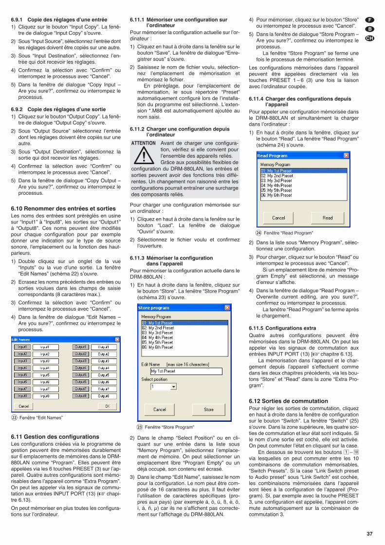
6.9.1 Copie des réglages dʼune entrée1) Cliquez sur le bouton “Input Copy”. La fenê-
tre de dialogue “Input Copy” sʼouvre.
2) Sous “Input Source”, sélectionnez lʼentrée dontles réglages doivent être copiés sur une autre.
3) Sous “Input Destination”, sélectionnez lʼen-trée qui doit recevoir les réglages.
4) Confirmez la sélection avec “Confirm” ouinterrompez le processus avec “Cancel”.
5) Dans la fenêtre de dialogue “Copy Input –Are you sure?”, confirmez ou interrompez leprocessus.
6.9.2 Copie des réglages dʼune sortie1) Cliquez sur le bouton “Output Copy”. La fenê-
tre de dialogue “Output Copy” sʼouvre.
2) Sous “Output Source” sélectionnez lʼentréedont les réglages doivent être copiés sur uneautre.
3) Sous “Output Destination”, sélectionnez lasortie qui doit recevoir les réglages.
4) Confirmez la sélection avec “Confirm” ouinterrompez le processus avec “Cancel”.
5) Dans la fenêtre de dialogue “Copy Output –Are you sure?”, confirmez ou interrompez leprocessus.
6.10 Renommer des entrées et sortiesLes noms des entrées sont préréglés en usinesur “Input1” à “Input8”, les sorties sur “Output1”à “Output8”. Ces noms peuvent être modifiéspour chaque configuration pour par exempledonner une indication sur le type de sourcesonore, lʼemplacement ou la fonction des haut-parleurs.
1) Double cliquez sur un onglet de la vue“Inputs” ou la vue dʼune sortie. La fenêtre“Edit Names” (schéma 22) sʼouvre.
2) Ecrasez les noms précédents des entrées ousorties voulues dans les champs de saisiecorrespondants (8 caractères max.).
3) Confirmez la sélection avec “Confirm” ouinterrompez le processus avec “Cancel”.
4) Dans la fenêtre de dialogue “Edit Names –Are you sure?”, confirmez ou interrompez leprocessus.
6.11 Gestion des configurationsLes configurations créées via le programme degestion peuvent être mémorisées durablementsur 6 emplacements de mémoires dans le DRM-880LAN comme “Program”. Elles peuvent êtreappelées via les 6 touches PRESET (3) sur lʼap-pareil. Quatre autres configurations sont mémo-risables dans lʼappareil comme “Extra Program”.On peut les appeler via les signaux de commu-tation aux entrées INPUT PORT (13) (� chapi-tre 6.13).
On peut mémoriser en plus toutes les configura-tions sur lʼordinateur.
6.11.1 Mémoriser une configuration surlʼordinateur
Pour mémoriser la configuration actuelle sur lʼor-dinateur :
1) Cliquez en haut à droite dans la fenêtre sur lebouton “Save”. La fenêtre de dialogue “Enre-gistrer sous” sʼouvre.
2) Saisissez le nom de fichier voulu, sélection-nez lʼemplacement de mémorisation etmémorisez le fichier.
En préréglage, pour lʼemplacement demémorisation, le sous répertoire “Preset”automatiquement configuré lors de lʼinstalla-tion du programme est sélectionné. Lʼexten-sion *.M88 est automatiquement ajoutée aunom saisi.
6.11.2 Charger une configuration depuislʼordinateur
Pour charger une configuration mémorisée surun ordinateur :
1) Cliquez en haut à droite dans la fenêtre sur lebouton “Load”. La fenêtre de dialogue“Ouvrir” sʼouvre.
2) Sélectionnez le fichier voulu et confirmezlʼouverture.
6.11.3 Mémoriser la configuration dans lʼappareil
Pour mémoriser la configuration actuelle dans leDRM-880LAN :
1) En haut à droite dans la fenêtre, cliquez surle bouton “Store”. La fenêtre “Store Program”(schéma 23) sʼouvre.
2) Dans le champ “Select Position” ou en cli-quant sur une entrée dans la liste sous“Memory Program”, sélectionnez lʼemplace-ment de mémoire. On peut sélectionner unemplacement libre “Program Empty” ou undéjà occupé, son contenu est écrasé.
3) Dans le champ “Edit Name”, saisissez le nompour la configuration. Le nom peut être com-posé de 16 caractères au plus. Il faut éviterlʼutilisation de caractères spécifiques (pro-pres aux pays) (par exemple ä, ö, ü, ß, è, ô,ì, á, ñ, μ) car ils ne sʼaffichent pas correcte-ment sur lʼaffichage du DRM-880LAN.
4) Pour mémoriser, cliquez sur le bouton “Store”ou interrompez le processus avec “Cancel”.
5) Dans la fenêtre de dialogue “Store Program –Are you sure?”, confirmez ou interrompez leprocessus.
La fenêtre “Store Program” se ferme unefois le processus de mémorisation terminé.
Les configurations mémorisées dans lʼappareilpeuvent être appelées directement via lestouches PRESET 1 – 6 (3) une fois la liaisonavec lʼordinateur coupée.
6.11.4 Charger des configurations depuislʼappareil
Pour appeler une configuration mémorisée dansle DRM-880LAN et simultanément la chargerdans lʼordinateur :
1) En haut à droite dans la fenêtre, cliquez surle bouton “Read”. La fenêtre “Read Program”(schéma 24) sʼouvre.
2) Dans la liste sous “Memory Program”, sélec-tionnez une configuration.
3) Pour charger, cliquez sur le bouton “Read” ouinterrompez le processus avec “Cancel”.
Si un emplacement libre de mémoire “Pro-gram Empty” est sélectionné, un messagedʼerreur sʼaffiche.
4) Dans la fenêtre de dialogue “Read Program –Overwrite current editing, are you sure?”,confirmez ou interrompez le processus.
La fenêtre “Read Program” se ferme aprèsle chargement.
6.11.5 Configurations extra Quatre autres configurations peuvent êtremémorisées dans le DRM-880LAN. On peut lesappeler via les signaux de commutation auxentrées INPUT PORT (13) [� chapitre 6.13].
La mémorisation dans lʼappareil et le char-gement depuis lʼappareil sʼeffectuent commedans les deux chapitres précédents, via les bou-tons “Store” et “Read” dans la zone “Extra Pro-gram”.
6.12 Sorties de commutationPour régler les sorties de commutation, cliquezen haut à droite dans la fenêtre de configurationsur le bouton “Switch”. La fenêtre “Switch” (25)sʼouvre. Dans la zone supérieure, les quatre sor-ties de commutation et leur état sont indiqués. Sile nom dʼune sortie est coché, elle est activée.On peut commuter lʼétat en cliquant sur la case.
En dessous se trouvent les boutons 1 – 10via lesquelles on peut commuter entre les 10combinaisons de commutation mémorisables,“Switch Presets”. Si la case “Link Switch presetto Audio preset” sous “Link Switch” est cochée,les combinaisons mémorisées dans lʼappareilsont liées à la configuration de lʼappareil (Pro-gram). Si, par exemple avec la touche PRESET3, une configuration est appelée, lʼappareil com-mute automatiquement sur la combinaison decommutation 3.
㉔ Fenêtre “Read Program”
㉓ Fenêtre “Store Program”
㉒ Fenêtre “Edit Names”
ATTENTION Avant de charger une configura-tion, vérifiez si elle convient pourlʼensemble des appareils reliés.Grâce aux possibilités flexibles de
configuration du DRM-880LAN, les entrées etsorties peuvent avoir des fonctions très diffé-rentes. Un changement non raisonné entre lesconfigurations pourrait entraîner une surchargedes composants reliés.
37
F
B
CH
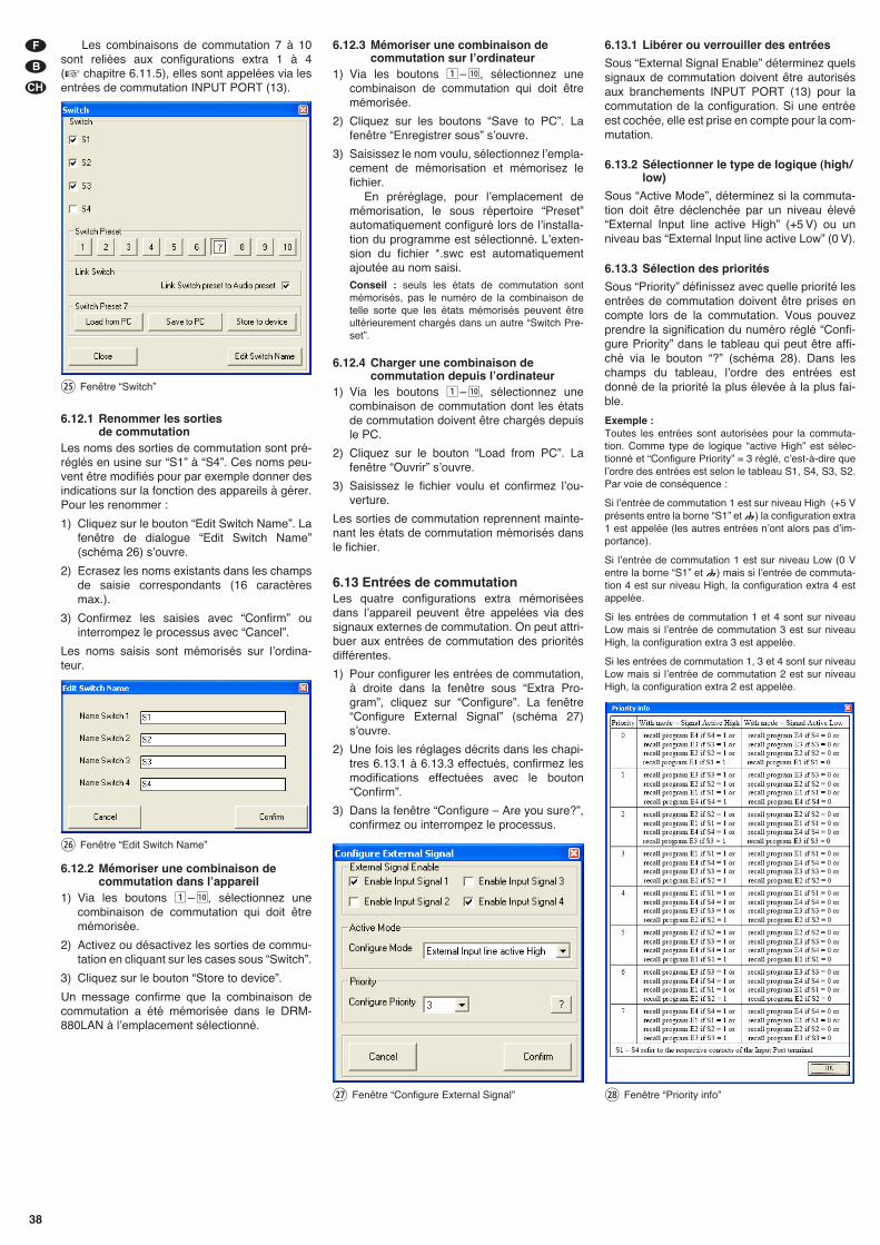
Les combinaisons de commutation 7 à 10sont reliées aux configurations extra 1 à 4(� chapitre 6.11.5), elles sont appelées via lesentrées de commutation INPUT PORT (13).
6.12.1 Renommer les sorties de commutation
Les noms des sorties de commutation sont pré-réglés en usine sur “S1” à “S4”. Ces noms peu-vent être modifiés pour par exemple donner desindications sur la fonction des appareils à gérer.Pour les renommer :
1) Cliquez sur le bouton “Edit Switch Name”. Lafenêtre de dialogue “Edit Switch Name”(schéma 26) sʼouvre.
2) Ecrasez les noms existants dans les champsde saisie correspondants (16 caractèresmax.).
3) Confirmez les saisies avec “Confirm” ouinterrompez le processus avec “Cancel”.
Les noms saisis sont mémorisés sur lʼordina-teur.
6.12.2 Mémoriser une combinaison decommutation dans lʼappareil
1) Via les boutons 1– 10, sélectionnez unecombinaison de commutation qui doit êtremémorisée.
2) Activez ou désactivez les sorties de commu-tation en cliquant sur les cases sous “Switch”.
3) Cliquez sur le bouton “Store to device”.
Un message confirme que la combinaison decommutation a été mémorisée dans le DRM-880LAN à lʼemplacement sélectionné.
6.12.3 Mémoriser une combinaison decommutation sur lʼordinateur
1) Via les boutons 1– 10, sélectionnez unecombinaison de commutation qui doit êtremémorisée.
2) Cliquez sur les boutons “Save to PC”. Lafenêtre “Enregistrer sous” sʼouvre.
3) Saisissez le nom voulu, sélectionnez lʼempla-cement de mémorisation et mémorisez lefichier.
En préréglage, pour lʼemplacement demémorisation, le sous répertoire “Preset”automatiquement configuré lors de lʼinstalla-tion du programme est sélectionné. Lʼexten-sion du fichier *.swc est automatiquementajoutée au nom saisi.Conseil : seuls les états de commutation sontmémorisés, pas le numéro de la combinaison detelle sorte que les états mémorisés peuvent êtreultérieurement chargés dans un autre “Switch Pre-set”.
6.12.4 Charger une combinaison decommutation depuis lʼordinateur
1) Via les boutons 1– 10, sélectionnez unecombinaison de commutation dont les étatsde commutation doivent être chargés depuisle PC.
2) Cliquez sur le bouton “Load from PC”. Lafenêtre “Ouvrir” sʼouvre.
3) Saisissez le fichier voulu et confirmez lʼou-verture.
Les sorties de commutation reprennent mainte-nant les états de commutation mémorisés dansle fichier.
6.13 Entrées de commutationLes quatre configurations extra mémoriséesdans lʼappareil peuvent être appelées via dessignaux externes de commutation. On peut attri-buer aux entrées de commutation des prioritésdifférentes.
1) Pour configurer les entrées de commutation,à droite dans la fenêtre sous “Extra Pro-gram”, cliquez sur “Configure”. La fenêtre“Configure External Signal” (schéma 27)sʼouvre.
2) Une fois les réglages décrits dans les chapi-tres 6.13.1 à 6.13.3 effectués, confirmez lesmodifications effectuées avec le bouton“Confirm”.
3) Dans la fenêtre “Configure – Are you sure?”,confirmez ou interrompez le processus.
6.13.1 Libérer ou verrouiller des entrées
Sous “External Signal Enable” déterminez quelssignaux de commutation doivent être autorisésaux branchements INPUT PORT (13) pour lacommutation de la configuration. Si une entréeest cochée, elle est prise en compte pour la com-mutation.
6.13.2 Sélectionner le type de logique (high/low)
Sous “Active Mode”, déterminez si la commuta-tion doit être déclenchée par un niveau élevé“External Input line active High” (+5 V) ou unniveau bas “External Input line active Low” (0 V).
6.13.3 Sélection des priorités
Sous “Priority” définissez avec quelle priorité lesentrées de commutation doivent être prises encompte lors de la commutation. Vous pouvezprendre la signification du numéro réglé “Confi-gure Priority” dans le tableau qui peut être affi-ché via le bouton “?” (schéma 28). Dans leschamps du tableau, lʼordre des entrées estdonné de la priorité la plus élevée à la plus fai-ble.
Exemple : Toutes les entrées sont autorisées pour la commuta-tion. Comme type de logique “active High” est sélec-tionné et “Configure Priority” = 3 réglé, cʼest-à-dire quelʼordre des entrées est selon le tableau S1, S4, S3, S2.Par voie de conséquence :
Si lʼentrée de commutation 1 est sur niveau High (+5 Vprésents entre la borne “S1” et ) la configuration extra1 est appelée (les autres entrées nʼont alors pas dʼim-portance).
Si lʼentrée de commutation 1 est sur niveau Low (0 Ventre la borne “S1” et ) mais si lʼentrée de commuta-tion 4 est sur niveau High, la configuration extra 4 estappelée.
Si les entrées de commutation 1 et 4 sont sur niveauLow mais si lʼentrée de commutation 3 est sur niveauHigh, la configuration extra 3 est appelée.
Si les entrées de commutation 1, 3 et 4 sont sur niveauLow mais si lʼentrée de commutation 2 est sur niveauHigh, la configuration extra 2 est appelée.
㉘ Fenêtre “Priority info”㉗ Fenêtre “Configure External Signal”
㉖ Fenêtre “Edit Switch Name”
㉕ Fenêtre “Switch”
38
F
B
CH
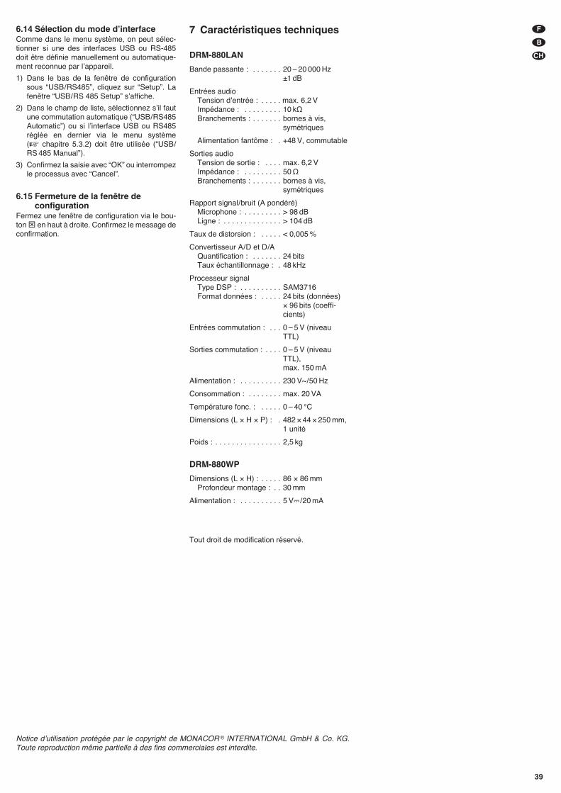
6.14 Sélection du mode dʼinterfaceComme dans le menu système, on peut sélec-tionner si une des interfaces USB ou RS-485doit être définie manuellement ou automatique-ment reconnue par lʼappareil.
1) Dans le bas de la fenêtre de configurationsous “USB/ RS485”, cliquez sur “Setup”. Lafenêtre “USB/ RS 485 Setup” sʼaffiche.
2) Dans le champ de liste, sélectionnez sʼil fautune commutation automatique (“USB/ RS485Automatic”) ou si lʼinterface USB ou RS485réglée en dernier via le menu système(� chapitre 5.3.2) doit être utilisée (“USB/RS 485 Manual”).
3) Confirmez la saisie avec “OK” ou interrompezle processus avec “Cancel”.
6.15 Fermeture de la fenêtre deconfiguration
Fermez une fenêtre de configuration via le bou-ton ⊠ en haut à droite. Confirmez le message deconfirmation.
7 Caractéristiques techniques
DRM-880LAN
Bande passante : . . . . . . . 20 – 20 000 Hz±1 dB
Entrées audioTension dʼentrée : . . . . . max. 6,2 VImpédance : . . . . . . . . . 10 kΩBranchements : . . . . . . . bornes à vis,
symétriques
Alimentation fantôme : . +48 V, commutable
Sorties audioTension de sortie : . . . . max. 6,2 VImpédance : . . . . . . . . . 50 ΩBranchements : . . . . . . . bornes à vis,
symétriques
Rapport signal/ bruit (A pondéré)Microphone : . . . . . . . . . > 98 dBLigne : . . . . . . . . . . . . . . > 104 dB
Taux de distorsion : . . . . . < 0,005 %
Convertisseur A/ D et D /AQuantification : . . . . . . . 24 bitsTaux échantillonnage : . 48 kHz
Processeur signalType DSP : . . . . . . . . . . SAM3716Format données : . . . . . 24 bits (données)
× 96 bits (coeffi-cients)
Entrées commutation : . . . 0 – 5 V (niveauTTL)
Sorties commutation : . . . . 0 – 5 V (niveauTTL),max. 150 mA
Alimentation : . . . . . . . . . . 230 V~ / 50 Hz
Consommation : . . . . . . . . max. 20 VA
Température fonc. : . . . . . 0 – 40 °C
Dimensions (L × H × P) : . 482 × 44 × 250 mm,1 unité
Poids : . . . . . . . . . . . . . . . . 2,5 kg
DRM-880WP
Dimensions (L × H) : . . . . . 86 × 86 mmProfondeur montage : . . 30 mm
Alimentation : . . . . . . . . . . 5 V�/ 20 mA
Tout droit de modification réservé.
39
F
B
CH
Notice dʼutilisation protégée par le copyright de MONACOR ® INTERNATIONAL GmbH & Co. KG.Toute reproduction même partielle à des fins commerciales est interdite.
Indice1 Elementi di comando
e collegamenti . . . . . . . . . . . . . . . . . . 40
1.1 Lato anteriore . . . . . . . . . . . . . . . . . . . 40
1.2 Lato posteriore . . . . . . . . . . . . . . . . . . 40
1.3 Unità di comando DRM-880WP . . . . . 41
2 Avvertenze di sicurezza . . . . . . . . . . 41
3 Possibilità dʻimpiego . . . . . . . . . . . . 41
4 Collocare e collegare lʻapparecchio 41
4.1 Fonti di segnali . . . . . . . . . . . . . . . . . . 41
4.2 Amplificatori o altri apparecchi . . . . . . 41
4.3 Segnali esterni di commutazione . . . . 41
4.4 Apparecchi da comandare . . . . . . . . . 41
4.5 Unità di comando DRM-880WP . . . . . 41
4.6 Computer . . . . . . . . . . . . . . . . . . . . . . 41
4.7 Collegamento con la rete . . . . . . . . . . 42
5 Funzionamento . . . . . . . . . . . . . . . . . 42
5.1 Accendere/spegnere . . . . . . . . . . . . . . 42
5.2 Scegliere la configurazione . . . . . . . . . 42
5.3 Impostazioni del sistema . . . . . . . . . . . 42
5.3.1 Impostare l'indirizzo IP . . . . . . . . . . . . 42
5.3.2 Selezionare lʼinterfaccia . . . . . . . . . . . 42
5.3.3 Numero dell'apparecchio per RS-485 . 42
5.3.4 Aprire una combinazione di commutazione . . . . . . . . . . . . . . . . . 42
5.3.5 Accoppiare le combinazioni di commutazione con la configurazione . 43
5.4 LED di stato . . . . . . . . . . . . . . . . . . . . . 43
5.5 Funzionamento tramite DRM-880WP . 43
5.5.1 Impostare lʼunità di comando . . . . . . . 43
6 Telecomando tramite un computer . 43
6.1 Installare il software per il PC . . . . . . . 43
6.1.1 Installare il driver dellʼinterfaccia . . . . . 43
6.2 Avviare il software PC . . . . . . . . . . . . . 43
6.2.1 Aggiungere degli apparecchi . . . . . . . . 43
6.2.2 Collegare o separare degli apparecchi 44
6.2.3 Dare un nome allʼapparecchio . . . . . . 44
6.2.4 Aprire la finestra di configurazione . . . 44
6.2.5 Eliminare degli apparecchi . . . . . . . . . 44
6.2.6 Memorizzare la costellazione degli apparecchi . . . . . . . . . . . . . . . . . 44
6.2.7 Caricare la costellazione degli apparecchi . . . . . . . . . . . . . . . . . 44
6.2.8 Cambiare lʼinterfaccia . . . . . . . . . . . . . 44
6.2.9 Impostare ID o indirizzo IP . . . . . . . . . 44
6.2.10 Terminare il programma . . . . . . . . . . 45
6.3 Visualizzazioni . . . . . . . . . . . . . . . . . . . 45
6.3.1 Unità di misura per il ritardo dei segnali . . . . . . . . . . . . . . . . . . . . . . 45
6.4 Configurare gli ingressi . . . . . . . . . . . . 45
6.4.1 Scegliere il livello del segnale . . . . . . . 45
6.4.2 Scegliere il modo di trasmissione dei segnali . . . . . . . . . . . . . . . . . . . . . . 45
6.4.3 Alimentazione phantom . . . . . . . . . . . . 45
6.4.4 Amplificazione . . . . . . . . . . . . . . . . . . . 46
6.4.4.1 Regolatore principale “Master Input Gain” . . . . . . . . . . . . . . 46
6.4.5 Regolazione toni (EQ) . . . . . . . . . . . . . 46
6.4.5.1 Risposta in frequenza . . . . . . . . . . . . 46
6.4.6 Soppressione del feedback (FBK) . . . 46
6.4.7 Inversione di fase . . . . . . . . . . . . . . . . 46
6.5 Configurare le uscite . . . . . . . . . . . . . . 46
6.5.1 Assegnare/ miscelare i segnali dʼingresso . . . . . . . . . . . . . . . . . . . . . . 46
6.5.2 Ritardo dei segnali . . . . . . . . . . . . . . . 47
6.5.3 Filtri passa-alto e passa-basso . . . . . . 47
6.5.4 Regolazione toni . . . . . . . . . . . . . . . . . 47
6.5.4.1 Risposta in frequenza . . . . . . . . . . . . 47
6.5.5 Compressore . . . . . . . . . . . . . . . . . . . . 47
6.5.6 Amplificazione . . . . . . . . . . . . . . . . . . . 48
6.5.7 Limitazione del livello (Limiter) . . . . . . 48
6.5.8 Inversione di fase . . . . . . . . . . . . . . . . 48
6.5.9 Regolatore principale . . . . . . . . . . . . . 48
6.6 Spia di stato . . . . . . . . . . . . . . . . . . . . 48
6.7 Messa in muto . . . . . . . . . . . . . . . . . . . 48
6.8 Accoppiamento dei canali . . . . . . . . . . 48
6.9 Copiare le impostazioni . . . . . . . . . . . . 49
6.9.1 Copiare le impostazioni di un ingresso 49
6.9.2 Copiare le impostazioni di unʼuscita . . 49
6.10 Rinominare ingressi e uscite . . . . . . . . 49
6.11 Gestione della configurazione . . . . . . . 49
6.11.1 Salvare la configurazione sul computer . . . . . . . . . . . . . . . . . . . 49
6.11.2 Caricare la configurazione dal computer . . . . . . . . . . . . . . . . . . . 49
6.11.3 Salvare la configurazione nellʻapparecchio . . . . . . . . . . . . . . . . 49
6.11.4 Caricare la configurazione dallʻapparecchio . . . . . . . . . . . . . . . . 49
6.11.5 Configurazioni extra . . . . . . . . . . . . . 49
6.12 Uscite di commutazione . . . . . . . . . . . 50
6.12.1 Cambiare nome alle uscite di commutazione . . . . . . . . . . . . . . . . 50
6.12.2 Salvare la combinazione di commutazione nellʻapparecchio . . 50
6.12.3 Salvare la combinazione di commutazione sul computer . . . . . 50
6.12.4 Caricare la combinazione di commutazione dal computer . . . . . 50
6.13 Ingressi di commutazione . . . . . . . . . . 50
6.13.1 Abilitare o bloccare gli ingressi . . . . . 50
6.13.2 Scegliere il tipo di logica (high / low) . . 50
6.13.3 Scegliere delle priorità . . . . . . . . . . . . 50
6.14 Scegliere il modo dʻinterfaccia . . . . . . 51
6.15 Chiudere la finestra di configurazione . 51
7 Dati tecnici . . . . . . . . . . . . . . . . . . . . . 51
A pagina 3, se aperta completamente, vedretetutti gli elementi di comando e i collegamentidescritti.
1 Elementi di comando e collegamenti
1.1 Lato anteriore
1 Spia PHANTOM POWER; è accesa se lʼali-mentazione phantom per gli ingressi permicrofoni è attivata
2 Display a LC
3 Tasti PRESET 1 – 6 per chiamare le configu-razioni memorizzate precedentementePer chiamare il menù per le impostazioni delsistema, tener premuto per alcuni secondi iltasto 5. Le funzioni dei tasti per le imposta-zioni del sistema sono descritte nel capitolo5.3.
4 LED di stato per i canali in/out CH 1 – CH 8
LIMITER – Limiter o compressore attivo
CLIP – Ingresso sovrapilotato (dopo EQ)
SIGNAL – Segnale per il canale dʼuscita presente
FBK – Soppressione feedback attiva
MIC – Ingresso per un microfono
LINE – Ingresso per segnali Line
5 Presa USB, tipo B, per collegare un compu-ter per il telecomando e per la configurazionedel DRM-880LAN
1.2 Lato posteriore
6 Interruttore rete POWER
7 Presa per il collegamento con una presa direte (230 V~ / 50 Hz) per mezzo del cavo indotazione
8 Portafusibile;Sostituire un fusibile difettoso sempre conuno dello stesso tipo
9 Presa RJ45 TCP/ IP per il collegamento di uncomputer per il comando remoto del DRM-880LAN tramite Ethernet; i due LED sopra lapresa segnalano la creazione del collega-mento e il traffico di dati
10 Presa RJ45 RS485 IN per il collegamento diun computer per il comando remoto oppuredellʼunità di controllo remoto DRM-880WP(fig. 3)
11 Presa RJ45 RS485 OUT per il collegamentodi un ulteriore apparecchio da gestire in casodi telecomando per mezzo di un computertramite la presa RS485 IN (10)
12 Uscite di commutazione S1 – S4 come mor-setti a vite*
13 Uscite di commutazione S1 – S4 come mor-setti a vite* per chiamare le configurazioniextra memorizzate prima
14 Uscite audio bilanciate CH 1 – CH 8 comemorsetti a vite*
15 Ingressi audio bilanciati CH 1 – CH 8 comemorsetti a vite*
* Per facilitare la connessione è possibile staccare dal-lʼapparecchio una fila completa di morsetti.
40
I
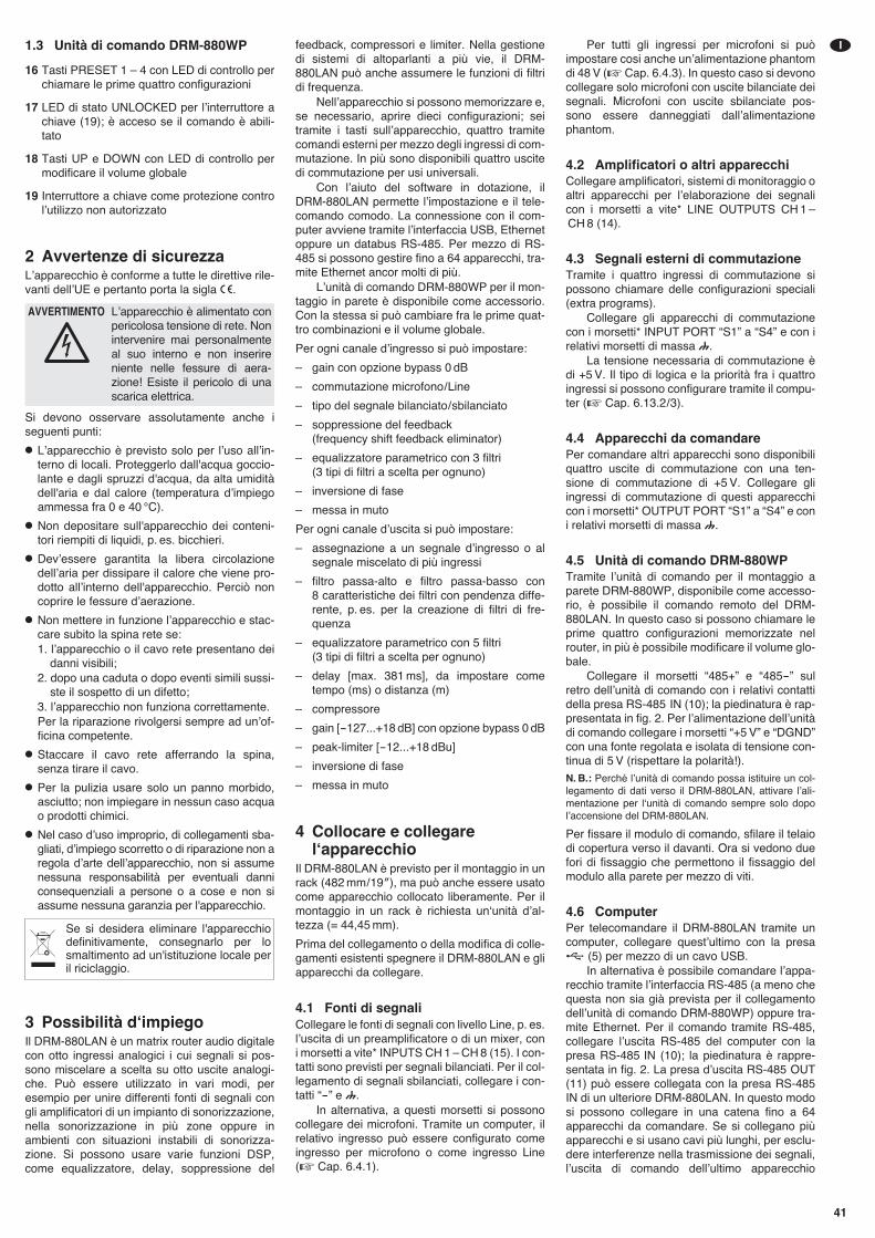
1.3 Unità di comando DRM-880WP
16 Tasti PRESET 1 – 4 con LED di controllo perchiamare le prime quattro configurazioni
17 LED di stato UNLOCKED per lʼinterruttore achiave (19); è acceso se il comando è abili-tato
18 Tasti UP e DOWN con LED di controllo permodificare il volume globale
19 Interruttore a chiave come protezione controlʼutilizzo non autorizzato
2 Avvertenze di sicurezzaLʼapparecchio è conforme a tutte le direttive rile-vanti dellʼUE e pertanto porta la sigla �.
Si devono osservare assolutamente anche iseguenti punti:
� Lʼapparecchio è previsto solo per lʼuso allʼin-terno di locali. Proteggerlo dall'acqua goccio-lante e dagli spruzzi d'acqua, da alta umiditàdell'aria e dal calore (temperatura dʼimpiegoammessa fra 0 e 40 °C).
� Non depositare sull'apparecchio dei conteni-tori riempiti di liquidi, p. es. bicchieri.
� Devʼessere garantita la libera circolazione dellʼaria per dissipare il calore che viene pro-dotto allʼinterno dell'apparecchio. Perciò noncoprire le fessure dʼaerazione.
� Non mettere in funzione lʼapparecchio e stac-care subito la spina rete se:1. lʼapparecchio o il cavo rete presentano dei
danni visibili;2. dopo una caduta o dopo eventi simili sussi-
ste il sospetto di un difetto;3. lʼapparecchio non funziona correttamente.Per la riparazione rivolgersi sempre ad unʼof-ficina competente.
� Staccare il cavo rete afferrando la spina,senza tirare il cavo.
� Per la pulizia usare solo un panno morbido,asciutto; non impiegare in nessun caso acquao prodotti chimici.
� Nel caso dʼuso improprio, di collegamenti sba-gliati, dʼimpiego scorretto o di riparazione non aregola dʼarte dellʼapparecchio, non si assumenessuna responsabilità per eventuali danniconsequenziali a persone o a cose e non siassume nessuna garanzia per l'apparecchio.
3 Possibilità dʻimpiegoIl DRM-880LAN è un matrix router audio digitalecon otto ingressi analogici i cui segnali si pos-sono miscelare a scelta su otto uscite analogi-che. Può essere utilizzato in vari modi, peresempio per unire differenti fonti di segnali congli amplificatori di un impianto di sonorizzazione,nella sonorizzazione in più zone oppure inambienti con situazioni instabili di sonorizza-zione. Si possono usare varie funzioni DSP,come equalizzatore, delay, soppressione del
feedback, compressori e limiter. Nella gestionedi sistemi di altoparlanti a più vie, il DRM-880LAN può anche assumere le funzioni di filtridi frequenza.
Nellʼapparecchio si possono memorizzare e,se necessario, aprire dieci configurazioni; seitramite i tasti sullʼapparecchio, quattro tramitecomandi esterni per mezzo degli ingressi di com-mutazione. In più sono disponibili quattro uscitedi commutazione per usi universali.
Con lʼaiuto del software in dotazione, ilDRM-880LAN permette lʼimpostazione e il tele-comando comodo. La connessione con il com-puter avviene tramite lʼinterfaccia USB, Ethernetoppure un databus RS-485. Per mezzo di RS-485 si possono gestire fino a 64 apparecchi, tra-mite Ethernet ancor molti di più.
Lʼunità di comando DRM-880WP per il mon-taggio in parete è disponibile come accessorio.Con la stessa si può cambiare fra le prime quat-tro combinazioni e il volume globale.
Per ogni canale dʼingresso si può impostare:
– gain con opzione bypass 0 dB
– commutazione microfono/ Line
– tipo del segnale bilanciato/ sbilanciato
– soppressione del feedback(frequency shift feedback eliminator)
– equalizzatore parametrico con 3 filtri(3 tipi di filtri a scelta per ognuno)
– inversione di fase
– messa in muto
Per ogni canale dʼuscita si può impostare:
– assegnazione a un segnale dʼingresso o alsegnale miscelato di più ingressi
– filtro passa-alto e filtro passa-basso con8 caratteristiche dei filtri con pendenza diffe-rente, p. es. per la creazione di filtri di fre-quenza
– equalizzatore parametrico con 5 filtri(3 tipi di filtri a scelta per ognuno)
– delay [max. 381 ms], da impostare cometempo (ms) o distanza (m)
– compressore
– gain [-127...+18 dB] con opzione bypass 0 dB
– peak-limiter [-12...+18 dBu]
– inversione di fase
– messa in muto
4 Collocare e collegarelʻapparecchio
Il DRM-880LAN è previsto per il montaggio in unrack (482 mm / 19″), ma può anche essere usatocome apparecchio collocato liberamente. Per ilmontaggio in un rack è richiesta unʻunità dʼal-tezza (= 44,45 mm).
Prima del collegamento o della modifica di colle-gamenti esistenti spegnere il DRM-880LAN e gliapparecchi da collegare.
4.1 Fonti di segnaliCollegare le fonti di segnali con livello Line, p. es.lʼuscita di un preamplificatore o di un mixer, coni morsetti a vite* INPUTS CH 1 – CH 8 (15). I con-tatti sono previsti per segnali bilanciati. Per il col-legamento di segnali sbilanciati, collegare i con-tatti “-” e .
In alternativa, a questi morsetti si possonocollegare dei microfoni. Tramite un computer, ilrelativo ingresso può essere configurato comeingresso per microfono o come ingresso Line(� Cap. 6.4.1).
Per tutti gli ingressi per microfoni si puòimpostare cosi anche unʼalimentazione phantomdi 48 V (�Cap. 6.4.3). In questo caso si devonocollegare solo microfoni con uscite bilanciate deisegnali. Microfoni con uscite sbilanciate pos-sono essere danneggiati dallʼalimentazionephantom.
4.2 Amplificatori o altri apparecchiCollegare amplificatori, sistemi di monitoraggio oaltri apparecchi per lʼelaborazione dei segnalicon i morsetti a vite* LINE OUTPUTS CH 1 –CH 8 (14).
4.3 Segnali esterni di commutazioneTramite i quattro ingressi di commutazione sipossono chiamare delle configurazioni speciali(extra programs).
Collegare gli apparecchi di commutazionecon i morsetti* INPUT PORT “S1” a “S4” e con irelativi morsetti di massa .
La tensione necessaria di commutazione èdi +5 V. Il tipo di logica e la priorità fra i quattroingressi si possono configurare tramite il compu-ter (� Cap. 6.13.2 / 3).
4.4 Apparecchi da comandarePer comandare altri apparecchi sono disponibiliquattro uscite di commutazione con una ten-sione di commutazione di +5 V. Collegare gliingressi di commutazione di questi apparecchicon i morsetti* OUTPUT PORT “S1” a “S4” e coni relativi morsetti di massa .
4.5 Unità di comando DRM-880WPTramite lʼunità di comando per il montaggio aparete DRM-880WP, disponibile come accesso-rio, è possibile il comando remoto del DRM-880LAN. In questo caso si possono chiamare leprime quattro configurazioni memorizzate nelrouter, in più è possibile modificare il volume glo-bale.
Collegare il morsetti “485+” e “485-” sulretro dellʼunità di comando con i relativi contattidella presa RS-485 IN (10); la piedinatura è rap-presentata in fig. 2. Per lʼalimentazione dellʼunitàdi comando collegare i morsetti “+5 V” e “DGND”con una fonte regolata e isolata di tensione con-tinua di 5 V (rispettare la polarità!).
N. B.: Perché lʼunità di comando possa istituire un col-legamento di dati verso il DRM-880LAN, attivare lʼali-mentazione per lʻunità di comando sempre solo dopolʼaccensione del DRM-880LAN.
Per fissare il modulo di comando, sfilare il telaiodi copertura verso il davanti. Ora si vedono duefori di fissaggio che permettono il fissaggio delmodulo alla parete per mezzo di viti.
4.6 ComputerPer telecomandare il DRM-880LAN tramite uncomputer, collegare questʼultimo con la presa
(5) per mezzo di un cavo USB.In alternativa è possibile comandare lʼappa-
recchio tramite lʼinterfaccia RS-485 (a meno chequesta non sia già prevista per il collegamentodellʼunità di comando DRM-880WP) oppure tra-mite Ethernet. Per il comando tramite RS-485,collegare lʼuscita RS-485 del computer con lapresa RS-485 IN (10); la piedinatura è rappre-sentata in fig. 2. La presa dʼuscita RS-485 OUT(11) può essere collegata con la presa RS-485IN di un ulteriore DRM-880LAN. In questo modosi possono collegare in una catena fino a 64apparecchi da comandare. Se si collegano piùapparecchi e si usano cavi più lunghi, per esclu-dere interferenze nella trasmissione dei segnali,lʼuscita di comando dellʼultimo apparecchio
Se si desidera eliminare l'apparecchiodefinitivamente, consegnarlo per losmaltimento ad un'istituzione locale peril riciclaggio.
AVVERTIMENTO Lʼapparecchio è alimentato conpericolosa tensione di rete. Nonintervenire mai personalmenteal suo interno e non inserireniente nelle fessure di aera-zione! Esiste il pericolo di unascarica elettrica.
41
I
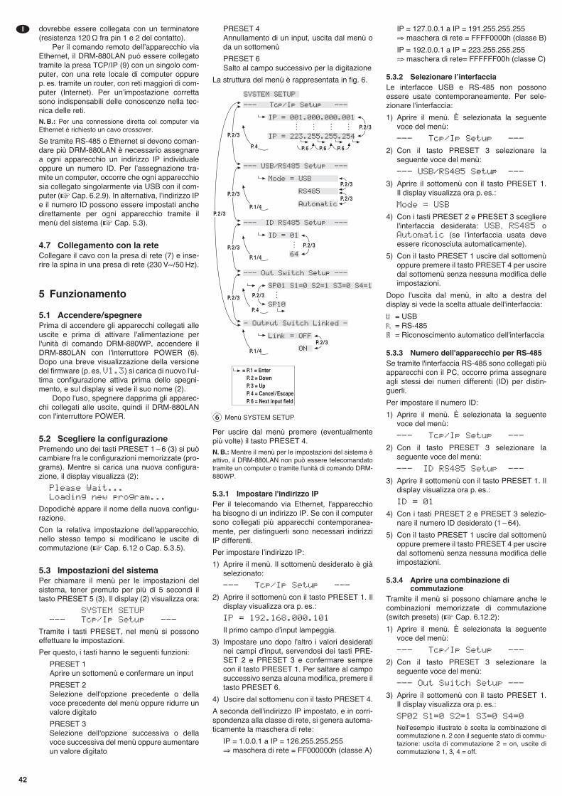
dovrebbe essere collegata con un terminatore(resistenza 120 Ω fra pin 1 e 2 del contatto).
Per il comando remoto dellʼapparecchio viaEthernet, il DRM-880LAN può essere collegatotramite la presa TCP/ IP (9) con un singolo com-puter, con una rete locale di computer oppurep. es. tramite un router, con reti maggiori di com-puter (Internet). Per unʼimpostazione correttasono indispensabili delle conoscenze nella tec-nica delle reti.N. B.: Per una connessione diretta col computer viaEthernet è richiesto un cavo crossover.
Se tramite RS-485 o Ethernet si devono coman-dare più DRM-880LAN è necessario assegnarea ogni apparecchio un indirizzo IP individualeoppure un numero ID. Per lʼassegnazione tra-mite un computer, occorre che ogni apparecchiosia collegato singolarmente via USB con il com-puter (� Cap. 6.2.9). In alternativa, lʼindirizzo IPe il numero ID possono essere impostati anchedirettamente per ogni apparecchio tramite ilmenù del sistema (� Cap. 5.3).
4.7 Collegamento con la reteCollegare il cavo con la presa di rete (7) e inse-rire la spina in una presa di rete (230 V~ / 50 Hz).
5 Funzionamento
5.1 Accendere/ spegnerePrima di accendere gli apparecchi collegati alleuscite e prima di attivare l'alimentazione perl'unità di comando DRM-880WP, accendere ilDRM-880LAN con l'interruttore POWER (6).Dopo una breve visualizzazione della versionedel firmware (p. es. V1.3) si carica di nuovo l'ul-tima configurazione attiva prima dello spegni-mento, e sul display si vede il suo nome (2).
Dopo l'uso, spegnere dapprima gli apparec-chi collegati alle uscite, quindi il DRM-880LANcon l'interruttore POWER.
5.2 Scegliere la configurazionePremendo uno dei tasti PRESET 1 – 6 (3) si puòcambiare fra le configurazioni memorizzate (pro-grams). Mentre si carica una nuova configura-zione, il display visualizza (2):
Please Wait...Loading new program...
Dopodiché appare il nome della nuova configu-razione.
Con la relativa impostazione dell'apparecchio,nello stesso tempo si modificano le uscite dicommutazione (� Cap. 6.12 o Cap. 5.3.5).
5.3 Impostazioni del sistemaPer chiamare il menù per le impostazioni delsistema, tener premuto per più di 5 secondi iltasto PRESET 5 (3). Il display (2) visualizza ora:
SYSTEM SETUP--- Tcp/Ip Setup ---
Tramite i tasti PRESET, nel menù si possonoeffettuare le impostazioni.
Per questo, i tasti hanno le seguenti funzioni:
PRESET 1Aprire un sottomenù e confermare un input
PRESET 2Selezione dell'opzione precedente o dellavoce precedente del menù oppure ridurre unvalore digitato
PRESET 3Selezione dell'opzione successiva o dellavoce successiva del menù oppure aumentareun valore digitato
PRESET 4Annullamento di un input, uscita dal menù oda un sottomenù
PRESET 6Salto al campo successivo per la digitazione
La struttura del menù è rappresentata in fig. 6.
Per uscire dal menù premere (eventualmentepiù volte) il tasto PRESET 4.N. B.: Mentre il menù per le impostazioni del sistema èattivo, il DRM-880LAN non può essere telecomandatotramite un computer o tramite l'unità di comando DRM-880WP.
5.3.1 Impostare l'indirizzo IPPer il telecomando via Ethernet, l'apparecchioha bisogno di un indirizzo IP. Se con il computersono collegati più apparecchi contemporanea-mente, per distinguerli sono necessari indirizziIP differenti.
Per impostare lʼindirizzo IP:
1) Aprire il menù. Il sottomenù desiderato è giàselezionato:
--- Tcp/Ip Setup ---
2) Aprire il sottomenù con il tasto PRESET 1. Ildisplay visualizza ora p. es.:
IP = 192.168.000.101
Il primo campo dʼinput lampeggia.
3) Impostare uno dopo l'altro i valori desideratinei campi d'input, servendosi dei tasti PRE-SET 2 e PRESET 3 e confermare semprecon il tasto PRESET 1. Per saltare al camposuccessivo senza alcuna modifica, premere iltasto PRESET 6.
4) Uscire dal sottomenu con il tasto PRESET 4.
A seconda dell'indirizzo IP impostato, e in corri-spondenza alla classe di rete, si genera automa-ticamente la maschera di rete:
IP = 1.0.0.1 a IP = 126.255.255.255⇒ maschera di rete = FF000000h (classe A)
IP = 127.0.0.1 a IP = 191.255.255.255⇒ maschera di rete = FFFF0000h (classe B)
IP = 192.0.0.1 a IP = 223.255.255.255⇒ maschera di rete= FFFFFF00h (classe C)
5.3.2 Selezionare lʼinterfacciaLe interfacce USB e RS-485 non possonoessere usate contemporaneamente. Per sele-zionare l'interfaccia:
1) Aprire il menù. È selezionata la seguentevoce del menù:
--- Tcp/Ip Setup ---
2) Con il tasto PRESET 3 selezionare laseguente voce del menù:
--- USB/RS485 Setup ---
3) Aprire il sottomenù con il tasto PRESET 1. Il display visualizza ora p. es.:
Mode = USB
4) Con i tasti PRESET 2 e PRESET 3 sceglierel'interfaccia desiderata: USB, RS485 oAutomatic (se l'interfaccia usata deveessere riconosciuta automaticamente).
5) Con il tasto PRESET 1 uscire dal sottomenùoppure premere il tasto PRESET 4 per usciredal sottomenù senza nessuna modifica delleimpostazioni.
Dopo l'uscita dal menù, in alto a destra deldisplay si vede la scelta attuale dell'interfaccia:
= USB= RS-485= Riconoscimento automatico dell'interfaccia
5.3.3 Numero dell'apparecchio per RS-485Se tramite l'interfaccia RS-485 sono collegati piùapparecchi con il PC, occorre prima assegnareagli stessi dei numeri differenti (ID) per distin-guerli.
Per impostare il numero ID:
1) Aprire il menù. È selezionata la seguentevoce del menù:
--- Tcp/Ip Setup ---
2) Con il tasto PRESET 3 selezionare laseguente voce del menù:
--- ID RS485 Setup ---
3) Aprire il sottomenù con il tasto PRESET 1. Ildisplay visualizza ora p. es.:
ID = 01
4) Con i tasti PRESET 2 e PRESET 3 selezio-nare il numero ID desiderato (1 – 64).
5) Con il tasto PRESET 1 uscire dal sottomenùoppure premere il tasto PRESET 4 per usciredal sottomenù senza nessuna modifica delleimpostazioni.
5.3.4 Aprire una combinazione dicommutazione
Tramite il menù si possono chiamare anche lecombinazioni memorizzate di commutazione(switch presets) (� Cap. 6.12.2):
1) Aprire il menù. È selezionata la seguentevoce del menù:
--- Tcp/Ip Setup ---
2) Con il tasto PRESET 3 selezionare laseguente voce del menù:
--- Out Switch Setup ---
3) Aprire il sottomenù con il tasto PRESET 1. Il display visualizza ora p. es.:
SP02 S1=0 S2=1 S3=0 S4=0
Nell'esempio illustrato è scelta la combinazione dicommutazione n. 2 con il seguente stato di commu-tazione: uscita di commutazione 2 = on, uscite dicommutazione 1, 3, 4 = off.
⑥ Menù SYSTEM SETUP
42
I
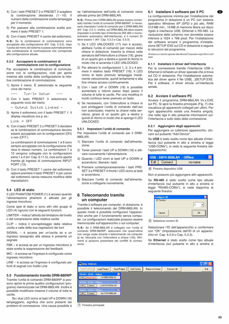
43
I4) Con i tasti PRESET 2 e PRESET 3 sceglierela combinazione desiderata (1 – 10). Ilnumero della combinazione scelta lampeggiaper il momento.
5) Per passare alla combinazione scelta pre-mere il tasto PRESET 1.
6) Con il tasto PRESET 4 uscire dal sottomenù.
N. B.: Se le combinazioni di commutazione sonoaccoppiate alla configurazione (� Cap. 5.3.5), dopolʼuscita dal menù del sistema si passa automaticamentealla combinazione di commutazione che corrispondealla configurazione attuale.
5.3.5 Accoppiare le combinazioni dicommutazione con la configurazione
Per accoppiare le combinazioni di commuta-zione con le configurazioni, cioè per aprireinsieme alla scelta della configurazione la rela-tiva combinazione di commutazione:
1) Aprire il menù. È selezionata la seguentevoce del menù:
--- Tcp/Ip Setup ---
2) Con il tasto PRESET 3 selezionare laseguente voce del menù:
- Output Switch Linked -
3) Aprire il sottomenù con il tasto PRESET 1. Ildisplay visualizza ora p. es.:
Link = OFF
4) Con il tasto PRESET 2 o PRESET 3 deciderese le combinazioni di commutazione devonoessere accoppiate con le configurazioni (ON)o non (OFF).
Le combinazioni di commutazione 1 a 6 sonosempre accoppiate con la configurazione chereca lo stesso numero. Le combinazioni 7 a10 vengono collegate con le configurazioniextra 1 a 4 (�Cap. 6.11.5), cioè sono apertetramite gli ingressi di commutazione INPUTPORT (13).
5) Con il tasto PRESET 1 uscire dal sottomenùoppure premere il tasto PRESET 4 per usciredal sottomenù senza nessuna modifica delleimpostazioni.
5.4 LED di statoIl LED PHANTOM POWER (1) è acceso quandolʼalimentazione phantom è attivata per gliingressi microfono.
Come spie di stato ci sono altri otto gruppi diLED (4) ognuno con le seguenti funzioni:
LIMITER – indica lʼattività del limitatore del livelloo del compressore della relativa uscita
CLIP – indica il sovrapilotaggio della relativauscita a valle della sua regolazioni dei toni
SIGNAL – è accesa per unʼuscita se a uningresso assegnato alla stessa è presente unsegnale
FBK – è accesa se per un ingresso microfono èstata scelta la soppressione del feedback
MIC – è accesa se lʼingresso è configurato comeingresso microfono
LINE – è accesa se lʼingresso è configurato perfonti di segnali con livello Line
5.5 Funzionamento tramite DRM-880WPTramite lʼunità di comando DRM-880WP si pos-sono aprire le prime quattro configurazioni (pro-grams) memorizzate nel DRM-880LAN. Inoltre èpossibile modificare insieme il volume di tutte leuscite.
Se i due LED vicino ai tasti UP e DOWN (18)lampeggiano, significa che sono presenti deiproblemi di connessione. Una causa possibile è
se lʼalimentazione dellʼunità di comando vieneattivata prima del DRM-880LAN.N. B.: Prima che il DRM-880LAN possa essere coman-dato tramite lʼunità di comando DRM-880WP, è neces-sario impostare lʼunità di comando per il DRM-880LAN(� Cap. 5.5.1). Inoltre, sul DRM-880LAN deve essereimpostato il corretto tipo dʼinterfaccia (RS 485 o ricono-scimento automatico dellʻinterfaccia), e il numero IDdeve essere 1 (� Cap. 5.3.2 e Cap. 5.3.3).
1) Se il LED UNLOCKED (17) non è acceso,abilitare lʼunità di comando per mezzo dellachiave in dotazione. Inserire la chiave nellaserratura dellʼinterruttore a chiave (19), giraredi un quarto giro a destra e quindi di ritorno inmodo che si accenda il LED UNLOCKED.
2) Per attivare le configurazioni 1, 2, 3 o 4 pre-mere il relativo tasto PRESET (16). Il LEDvicino al tasto premuto lampeggia inizial-mente velocemente, quindi lentamente e allafine rimane acceso continuamente.
3) Con i tasti UP e DOWN (18) è possibileaumentare o ridurre passo dopo passo ilvolume di tutte le uscite. Per una modifica inmodo continuo tener premuto un tasto.
4) Se necessario, con lʼinterruttore a chiave sipuò proteggere lʼunità di comando dallʼusonon autorizzato; inserire la chiave nella ser-ratura, girare di un quarto giro a destra equindi di ritorno in modo che si spenga il LEDUNLOCKED.
5.5.1 Impostare lʼunità di comandoPer impostare lʼunità di comando per il DRM-880LAN:
1) Staccare lʼunità di comando dallʻalimenta-zione.
2) Tener premuti i tasti UP e DOWN (18) e atti-vare nuovamente lʻalimentazione.
3) Quando i LED vicini ai tasti UP e DOWN siaccendono, liberare i tasti.
4) Premere contemporaneamente i tasti PRE-SET 3 e PRESET 4 finché i LED vicino ai tastisi accendono.
5) Staccare lʼunità di comando dallʻalimenta-zione e collegarla nuovamente.
6 Telecomando tramite un computer
Tramite il software per computer, in dotazione, èpossibile il telecomando del DRM-880LAN. Inquesto modo è possibile configurare lʼapparec-chio anche per il funzionamento senza compu-ter. Le configurazioni realizzate possono esserememorizzate sullʼapparecchio o sul computer.N. B.: Se il DRM-880LAN è collegato con lʼunità dicomando DRM-880WP, assicurarsi che questʼultimanon venga usata durante il telecomando via computer[p. es. bloccarla con lʼinterruttore a chiave (19)]. Altri-menti si possono presentare dei conflitti di connes-sione.
6.1 Installare il software per il PCLa configurazione minima per lʼinstallazione delprogramma in dotazione è un PC con sistemaoperativo Windows XP (SP2) o più alto, RAM512 MB min., 10 MB di memoria libera sul discorigido e interfacce USB, Ethernet o RS-485. Larisoluzione dello schermo non dovrebbe essereinferiore a 1024 × 768 pixel. Per lʼinstallazionedel software avviare il programma dʼinstalla-zione SETUP.EXE sul CD in dotazione e seguirele istruzioni del programma.
Windows è un marchio registrato della Microsoft Corporation negli USA e in altripaesi.
6.1.1 Installare il driver dellʼinterfacciaPer la connessione tramite lʼinterfaccia USB oEthernet è richiesto un driver speciale che si trovasul CD in dotazione. Per lʼinstallazione automa-tica del driver aprire il file USB[…]SETUP.EXE.Per il software, il driver simula unʼinterfacciaseriale.
6.2 Avviare il software PCAvviare il programma DRM-880LAN Vx.x.EXEsul PC. Si apre la finestra principale (Fig. 7) chevisualizza gli apparecchi collegati per ultimi. Perogni apparecchio esiste una finestra singola,che nella riga in alto presenta informazioni sul-lʼinterfaccia e sullo stato della connessione.
6.2.1 Aggiungere degli apparecchiPer aggiungere un (ulteriore) apparecchio, clic-care sul pulsante “Add Device”.
Se USB è stato scelto come tipo attuale dʻinter-faccia (sul pulsante in alto a sinistra si legge“USB-COMx”), si vede la seguente finestra del-lʼapparecchio:
Non si possono più aggiungere altri apparecchi.
Se RS-485 è stato scelto come tipo attualedʻinterfaccia (sul pulsante in alto a sinistra silegge “RS485-COMx”), si vede dapprima laseguente finestra:
Selezionare lʼID dellʼapparecchio e confermarecon “OK” (Impostazione dellʼID di un apparec-chio � Cap. 6.2.9 o Cap. 5.3.3).
Se Ethernet è stato scelto come tipo attualedʻinterfaccia (sul pulsante in alto a sinistra si
⑨ Selezione numero ID
⑧ Finestra dispositivo USB
⑦ Finestra principale
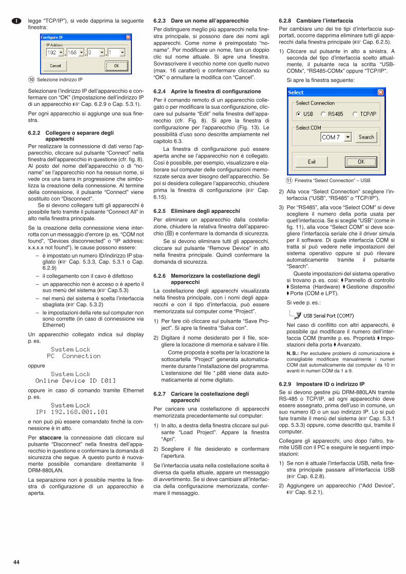
legge “TCP/ IP”), si vede dapprima la seguentefinestra:
Selezionare lʼindirizzo IP dellʼapparecchio e con-fermare con “OK” (Impostazione dellʼindirizzo IPdi un apparecchio � Cap. 6.2.9 o Cap. 5.3.1).
Per ogni apparecchio si aggiunge una sua fine-stra.
6.2.2 Collegare o separare degliapparecchi
Per realizzare la connessione di dati verso lʼap-parecchio, cliccare sul pulsante “Connect” nellafinestra dellʼapparecchio in questione (cfr. fig. 8).Al posto del nome dellʼapparecchio o di “no-name” se lʼapparecchio non ha nessun nome, sivede ora una barra in progressione che simbo-lizza la creazione della connessione. Al terminedella connessione, il pulsante “Connect” vienesostituito con “Disconnect”.
Se si devono collegare tutti gli apparecchi èpossibile farlo tramite il pulsante “Connect All” inalto nella finestra principale.
Se la creazione della connessione viene inter-rotta con un messaggio dʼerrore (p. es. “COM notfound”, “Devices disconnected” o “IP address:x.x.x.x not found”), le cause possono essere:
– è impostato un numero ID/indirizzo IP sba-gliato (� Cap. 5.3.3, Cap. 5.3.1 o Cap.6.2.9)
– il collegamento con il cavo è difettoso
– un apparecchio non è acceso o è aperto ilsuo menù del sistema (� Cap.5.3)
– nel menù del sistema è scelta lʼinterfacciasbagliata (� Cap. 5.3.2)
– le impostazioni della rete sul computer nonsono corrette (in caso di connessione viaEthernet)
Un apparecchio collegato indica sul displayp. es.
System LockPC Connection
oppure
System LockOnline Device ID [01]
oppure in caso di comando tramite Ethernetp. es.
System LockIP: 192.168.001.101
e non può più essere comandato finché la con-nessione è in atto.
Per staccare la connessione dati cliccare sulpulsante “Disconnect” nella finestra dellʼappa-recchio in questione e confermare la domanda disicurezza che segue. A questo punto è nuova-mente possibile comandare direttamente ilDRM-880LAN.
La separazione non è possibile mentre la fine-stra di configurazione di un apparecchio èaperta.
6.2.3 Dare un nome allʼapparecchio
Per distinguere meglio più apparecchi nella fine-stra principale, si possono dare dei nomi agliapparecchi. Come nome è preimpostato “no-name”. Per modificare un nome, fare un doppioclic sul nome attuale. Si apre una finestra.Sovrascrivere il vecchio nome con quello nuovo(max. 16 caratteri) e confermare cliccando su“OK” o annullare la modifica con “Cancel”.
6.2.4 Aprire la finestra di configurazione
Per il comando remoto di un apparecchio colle-gato o per modificare la sua configurazione, clic-care sul pulsante “Edit” nella finestra dellʼappa-recchio (cfr. Fig. 8). Si apre la finestra diconfigurazione per lʼapparecchio (Fig. 13). Lepossibilità dʼuso sono descritte ampiamente nelcapitolo 6.3.
La finestra di configurazione può essereaperta anche se lʼapparecchio non è collegato.Così è possibile, per esempio, visualizzare e ela-borare sul computer delle configurazioni memo-rizzate senza aver bisogno dellʼapparecchio. Sepoi si desidera collegare lʼapparecchio, chiudereprima la finestra di configurazione (� Cap.6.15).
6.2.5 Eliminare degli apparecchi
Per eliminare un apparecchio dalla costella-zione, chiudere la relativa finestra dellʼapparec-chio (⊠) e confermare la domanda di sicurezza.
Se si devono eliminare tutti gli apparecchi,cliccare sul pulsante “Remove Device” in altonella finestra principale. Quindi confermare ladomanda di sicurezza.
6.2.6 Memorizzare la costellazione degliapparecchi
La costellazione degli apparecchi visualizzatanella finestra principale, con i nomi degli appa-recchi e con il tipo dʼinterfaccia, può esserememorizzata sul computer come “Project”.
1) Per fare ciò cliccare sul pulsante “Save Pro-ject”. Si apre la finestra “Salva con”.
2) Digitare il nome desiderato per il file, sce-gliere la locazione di memoria e salvare il file.
Come proposta è scelta per la locazione lasottocartella “Project” generata automatica-mente durante lʼinstallazione del programma.Lʼestensione del file *.p88 viene data auto-maticamente al nome digitato.
6.2.7 Caricare la costellazione degliapparecchi
Per caricare una costellazione di apparecchimemorizzata precedentemente sul computer:
1) In alto, a destra della finestra cliccare sul pul-sante “Load Project”. Appare la finestra“Apri”.
2) Scegliere il file desiderato e confermarelʼapertura.
Se lʼinterfaccia usata nella costellazione scelta èdiversa da quella attuale, appare un messaggiodi avvertimento. Se si deve cambiare allʼinterfac-cia della configurazione memorizzata, confer-mare il messaggio.
6.2.8 Cambiare lʼinterfaccia
Per cambiare uno dei tre tipi dʼinterfaccia sup-portati, occorre dapprima eliminare tutti gli appa-recchi dalla finestra principale (� Cap. 6.2.5).
1) Cliccare sul pulsante in alto a sinistra. Aseconda del tipo dʼinterfaccia scelto attual-mente, il pulsante reca la scritta “USB-COMx”, “RS485-COMx” oppure “TCP/ IP”.
Si apre la finestra seguente:
2) Alla voce “Select Connection” scegliere lʼin-terfaccia (“USB”, “RS485” o ”TCP/ IP”).
3) Per “RS485”, alla voce “Select COM” si devescegliere il numero della porta usata perquellʼinterfaccia. Se si sceglie “USB” (come infig. 11), alla voce “Select COM” si deve sce-gliere lʼinterfaccia seriale che il driver simulaper il software. Di quale interfaccia COM sitratta si può vedere nelle impostazioni delsistema operativo oppure si può rilevareautomaticamente tramite il pulsante“Search”.
Queste impostazioni del sistema operativosi trovano p. es. cosi: ➧Pannello di controllo➧Sistema (Hardware) ➧Gestione dispositivi➧Porte (COM e LPT).
Si vede p. es.:
Nel caso di conflitto con altri apparecchi, èpossibile qui modificare il numero dellʼinter-faccia COM (tramite p. es. Proprietà ➧ Impo-stazioni della porta ➧Avanzato.
N. B.: Per escludere problemi di comunicazione èconsigliabile modificare manualmente i numeriCOM dati automaticamente dal computer da 10 inavanti in numeri COM da 1 a 9.
6.2.9 Impostare ID o indirizzo IP
Se si devono gestire più DRM-880LAN tramiteRS-485 o TCP/ IP, ad ogni apparecchio deveessere assegnato, prima dellʼuso in comune, unsuo numero ID o un suo indirizzo IP. Lo si puòfare tramite il menù del sistema (� Cap. 5.3.1opp. 5.3.3) oppure, come descritto qui, tramite ilcomputer.
Collegare gli apparecchi, uno dopo lʼaltro, tra-mite USB con il PC e eseguire le seguenti impo-stazioni:
1) Se non è attuale lʼinterfaccia USB, nella fine-stra principale passare allʼinterfaccia USB(� Cap. 6.2.8).
2) Aggiungere un apparecchio (“Add Device”,� Cap. 6.2.1).
⑪ Finestra “Select Connection” – USB
⑩ Selezione indirizzo IP
44
I
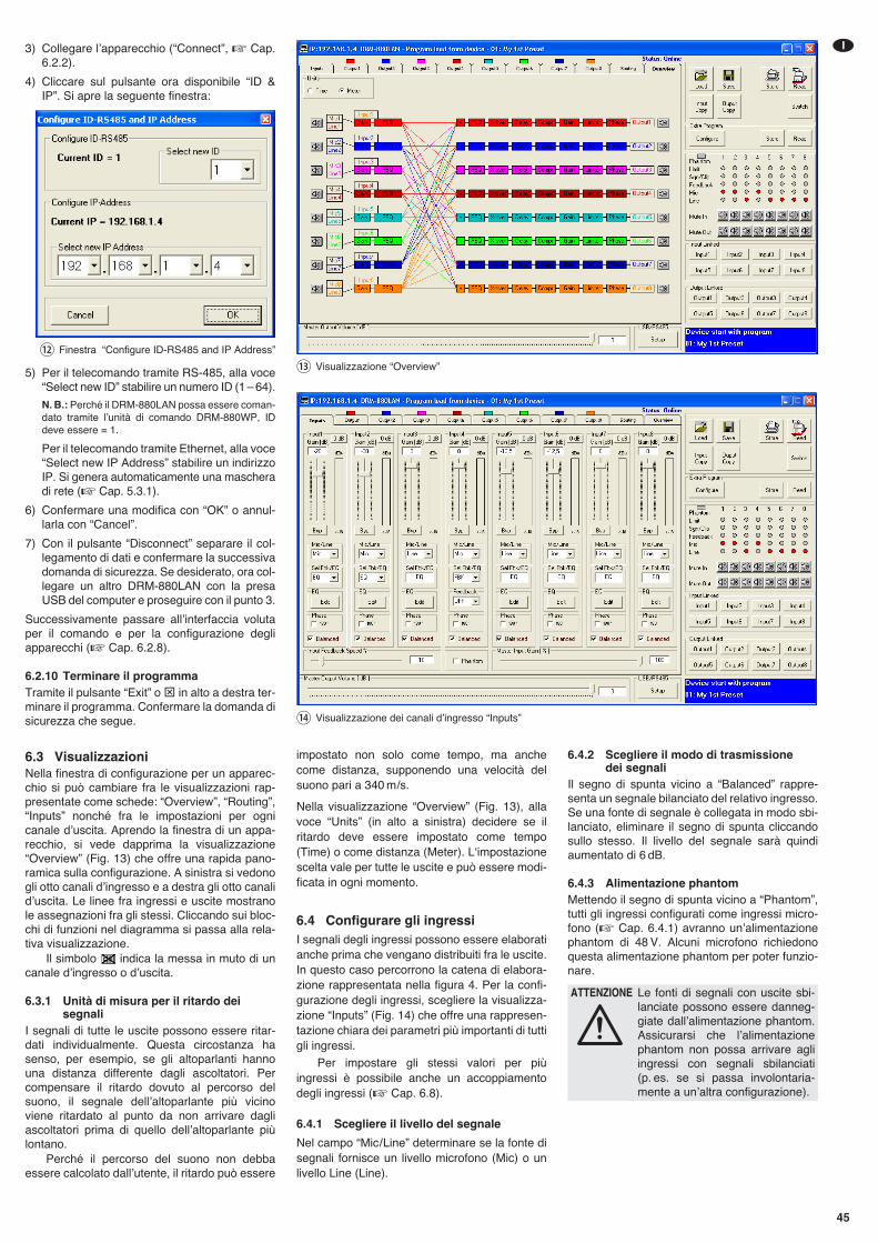
3) Collegare lʼapparecchio (“Connect”, � Cap.6.2.2).
4) Cliccare sul pulsante ora disponibile “ID &IP”. Si apre la seguente finestra:
5) Per il telecomando tramite RS-485, alla voce“Select new ID” stabilire un numero ID (1 – 64).
N. B.: Perché il DRM-880LAN possa essere coman-dato tramite lʼunità di comando DRM-880WP, IDdeve essere = 1.
Per il telecomando tramite Ethernet, alla voce“Select new IP Address” stabilire un indirizzoIP. Si genera automaticamente una mascheradi rete (� Cap. 5.3.1).
6) Confermare una modifica con “OK” o annul-larla con “Cancel”.
7) Con il pulsante “Disconnect” separare il col-legamento di dati e confermare la successivadomanda di sicurezza. Se desiderato, ora col-legare un altro DRM-880LAN con la presaUSB del computer e proseguire con il punto 3.
Successivamente passare allʼinterfaccia volutaper il comando e per la configurazione degliapparecchi (� Cap. 6.2.8).
6.2.10 Terminare il programmaTramite il pulsante “Exit” o ⊠ in alto a destra ter-minare il programma. Confermare la domanda disicurezza che segue.
6.3 VisualizzazioniNella finestra di configurazione per un apparec-chio si può cambiare fra le visualizzazioni rap-presentate come schede: “Overview”, “Routing”,“Inputs” nonché fra le impostazioni per ognicanale dʼuscita. Aprendo la finestra di un appa-recchio, si vede dapprima la visualizzazione“Overview” (Fig. 13) che offre una rapida pano-ramica sulla configurazione. A sinistra si vedonogli otto canali dʼingresso e a destra gli otto canalidʼuscita. Le linee fra ingressi e uscite mostranole assegnazioni fra gli stessi. Cliccando sui bloc-chi di funzioni nel diagramma si passa alla rela-tiva visualizzazione.
Il simbolo indica la messa in muto di uncanale dʼingresso o dʼuscita.
6.3.1 Unità di misura per il ritardo deisegnali
I segnali di tutte le uscite possono essere ritar-dati individualmente. Questa circostanza hasenso, per esempio, se gli altoparlanti hannouna distanza differente dagli ascoltatori. Percompensare il ritardo dovuto al percorso delsuono, il segnale dellʼaltoparlante più vicinoviene ritardato al punto da non arrivare dagliascoltatori prima di quello dellʼaltoparlante piùlontano.
Perché il percorso del suono non debbaessere calcolato dallʼutente, il ritardo può essere
⑫ Finestra “Configure ID-RS485 and IP Address”
45
I
impostato non solo come tempo, ma anchecome distanza, supponendo una velocità delsuono pari a 340 m /s.
Nella visualizzazione “Overview” (Fig. 13), allavoce “Units” (in alto a sinistra) decidere se ilritardo deve essere impostato come tempo(Time) o come distanza (Meter). Lʻimpostazionescelta vale per tutte le uscite e può essere modi-ficata in ogni momento.
6.4 Configurare gli ingressiI segnali degli ingressi possono essere elaboratianche prima che vengano distribuiti fra le uscite.In questo caso percorrono la catena di elabora-zione rappresentata nella figura 4. Per la confi-gurazione degli ingressi, scegliere la visualizza-zione “Inputs” (Fig. 14) che offre una rappresen-tazione chiara dei parametri più importanti di tuttigli ingressi.
Per impostare gli stessi valori per piùingressi è possibile anche un accoppiamentodegli ingressi (� Cap. 6.8).
6.4.1 Scegliere il livello del segnale
Nel campo “Mic / Line” determinare se la fonte disegnali fornisce un livello microfono (Mic) o unlivello Line (Line).
6.4.2 Scegliere il modo di trasmissione dei segnali
Il segno di spunta vicino a “Balanced” rappre-senta un segnale bilanciato del relativo ingresso.Se una fonte di segnale è collegata in modo sbi-lanciato, eliminare il segno di spunta cliccandosullo stesso. Il livello del segnale sarà quindiaumentato di 6 dB.
6.4.3 Alimentazione phantomMettendo il segno di spunta vicino a “Phantom”,tutti gli ingressi configurati come ingressi micro-fono (� Cap. 6.4.1) avranno unʼalimentazionephantom di 48 V. Alcuni microfono richiedonoquesta alimentazione phantom per poter funzio-nare.
ATTENZIONE Le fonti di segnali con uscite sbi-lanciate possono essere danneg-giate dallʼalimentazione phantom.Assicurarsi che lʼalimentazionephantom non possa arrivare agliingressi con segnali sbilanciati(p. es. se si passa involontaria-mente a unʼaltra configurazione).
⑭ Visualizzazione dei canali dʼingresso “Inputs”
⑬ Visualizzazione “Overview”
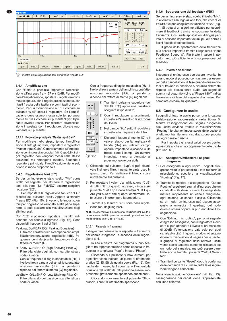
6.4.6 Soppressione del feedback (FBK)
Se per un ingresso è stato scelto il livello “Mic”,in alternativa alla regolazione toni, alla voce “SelFbk/ EQ” si può scegliere la funzione “FBK” (Fig.14). Si tratta di un algoritmo efficace per soppri-mere il feedback tramite lo spostamento dellafrequenza. Così, nelle applicazioni di lingua par-lata si possono impostare volumi più alti senza ifischi fastidiosi del feedback.
Il grado dello spostamento della frequenzapuò essere impostato tramite il regolatore “InputFeedback Speed %”. Più è alto il valore impo-stato, tanto più efficiente è la soppressione delfeedback.
6.4.7 Inversione di fase
Il segnale di un ingresso può essere invertito. Inquesto modo si possono contrastare per esem-pio delle cancellazioni di fase quando due micro-foni si trovano in direzione o distanza differenterispetto alla stessa fonte audio. Un segno dispunta nel quadrato vicino a “Phase 180°” indicalʼinversione di fase del segnale dʼingresso. Percambiare cliccare sul quadrato.
6.5 Configurare le usciteI segnali di tutte le uscite percorrono la catenadʼelaborazione rappresentata nella figura 5.Mentre lʼassegnazione dei segnali dʼingressoalle uscite avviene tramite la visualizzazione“Routing”, le ulteriori impostazioni delle uscite sieffettuano tramite una visualizzazione propriaper ogni canale dʼuscita.
Per impostare gli stessi valori per più uscite,è possibile anche un accoppiamento delle uscite(� Cap. 6.8).
6.5.1 Assegnare/ miscelare i segnalidʼingresso
1) Per assegnare a ogni uscita i segnali dʼin-gresso voluti e per stabilire il loro rapporto dimiscelazione, scegliere la visualizzazione“Routing” (Fig. 17).
2) Tramite la matrice dʼassegnazione “OutputRouting” scegliere i segnali dʼingresso che uncanale dʼuscita deve ricevere. Ogni riga dellamatrice rappresenta un canale dʼingresso,ogni colonna un canale dʼuscita. Cliccandosu un nodo, un ingresso può essere asse-gnato a unʼuscita (il quadrato del nododiventa rosso) oppure si può annullare lʼas-segnazione.
3) Con “Editing mix routing”, per ogni segnaledʼingresso assegnato, con il regolatore a cur-sore si può attenuare il livello di un massimodi 30 dB (lʼattenuazione vale solo per quelcanale dʼuscita). In questo modo si ottengonodifferenti miscelazioni di segnali per le uscite.Il gruppo di regolatori della relativa uscitaviene scelto automaticamente cliccando suun nodo della matrice, ma può essere cam-biato anche tramite i pulsanti “Output Selec-ted”.
4) Tramite il pulsante “Reset”, dopo la confermadella domanda di sicurezza, tutte le assegna-zioni vengono cancellate.
Nella visualizzazione “Overview” (� Fig. 13),lʼassegnazione dei canali viene rappresentatacon linee colorate.
46
I
6.4.4 AmplificazioneCon “Gain” è possibile impostare lʼamplifica-zione allʼingresso fra -127 e +12 dB. Per modifi-care lʼamplificazione, spostare il regolatore con ilmouse oppure, con il regolatore selezionato, coni tasti freccia della tastiera o con i tasti di scorri-mento. Per un ritorno veloce a 0 dB, cliccare sulpulsante “0 dB” sopra il regolatore. Se lʼamplifi-cazione deve essere messa solo temporanea-mente su 0 dB, cliccare sul pulsante “Byp”. Il pul-sante diventa rosso. Per ritornare al lʼamplifica-zione impostata con il regolatore, cliccare nuo-vamente sul pulsante.
6.4.4.1 Regolatore principale “Master Input Gain”Per modificare nello stesso tempo lʼamplifica-zione di tutti gli ingressi, impostare il regolatore“Master Input Gain”. Contrariamente allʼimposta-zione con ingressi accoppiati (�Cap. 6.8), i sin-goli regolatori non vengono messi nella stessaposizione, ma rimangono invariati. Secondo ilregolatore principale, lʼamplificazione viene soloridotto in modo proporzionale.
6.4.5 Regolazione toni (EQ)Se per un ingresso è stato scelto “Mic” comelivello del segnale, per sfruttare la regolazionetoni, alla voce “Sel Fbk/ EQ” occorre sceglierelʼopzione “EQ”.
Per impostare la regolazione toni con “EQ”,cliccare sul pulsante “Edit”. Appare la finestra“Inputs EQ” (Fig. 15). Si vedono le impostazionitoni per lʼingresso selezionato. Nella parte supe-riore, si può passare alla visualizzazione deglialtri ingressi.
Con “EQ” si possono impostare i tre filtri indi-pendenti del canale dʼingresso (Fig. 16). Sonodisponibili i seguenti tipi di filtri:
Peaking_Eq / PEAK EQ (Peaking Equalizer)Filtro con caratteristica a campana con ampli-ficazione/attenuazione regolabile (dB), fre-quenza centrale (center frequency) (Hz) efattore di merito (Q)
Hi-Shelv_Q / HiSHF Q (High Shelving Filter Q)Filtro bilanciato degli alti con caratteristica acoda di vacca Con la frequenza di taglio impostabile (Hz), illivello si trova a metà dellʼamplificazione/atte-nuazione impostata (dB); la pendenzadipende dal fattore di merito (Q) regolabile.
Lo-Shelv_Q / LoSHF Q (Low Shelving Filter Q)Filtro bilanciato dei bassi con caratteristica acoda di vacca
Con la frequenza di taglio impostabile (Hz), illivello si trova a metà dellʼamplificazione/atte-nuazione impostata (dB); la pendenzadipende dal fattore di merito (Q) regolabile
1) Tramite il pulsante superiore (qui“PEAK EQ”) aprire una finestra escegliere il tipo di filtro.
2) Con il regolatore a scorrimentoimpostare lʼaumento o la riduzionedel livello.
3) Nel campo “Hz” sotto il regolatoreimpostare la frequenza del filtro.
4) Digitare il fattore di merito (Q) o ilvalore relativo per la larghezza dibanda (Bw) nel relativo campooppure impostarlo cliccando sullefrecce sotto i campi. Un numeroimpostato viene arrotondato alprossimo valore possibile.
5) Cliccando sul pulsante “Byp”, si può disatti-vare il singolo filtro. Il pulsante sarà rosso inquesto caso. Per riattivare il filtro, cliccarenuovamente sul pulsante.
6) Per resettare i valori dʼamplificazione (0 dB)di tutti i filtri di questo ingresso, cliccare sulpulsante “Flat Eq” e nella finestra “Flat Eq –Are you sure?” che si apre, confermare lʼin-tenzione o interrompere la procedura.
7) Tramite il pulsante “Exit” uscire dalla regola-zione toni degli ingressi.
N. B.: In alternativa, lʼaumento/la riduzione del livello ela frequenza dei filtri possono essere impostati anche inmodo grafico (� Cap. 6.4.5.1).
6.4.5.1 Risposta in frequenza
Il diagramma visualizza la risposta in frequenzadel canale dʼingresso, a seconda della regola-zione toni.
In alto a destra del diagramma si può sce-gliere fra rappresentazione come risposta in fre-quenza in ampiezza “Mag” o in fase “Phase”.
Cliccando sul pulsante “Show cursor”, perogni filtro viene indicato un punto di riferimentografico ( , , ) vicino alla curva (Fig. 15). Conlʼaiuto del mouse, la frequenza e lʼaumento/lariduzione del livello dei filtri possono essere rap-presentati graficamente spostando questi punti.
Cliccando nuovamente sul pulsante “Showcursor”, i punti di riferimento spariscono.
⑯ “EQ”
⑮ Finestra della regolazione toni dʼingresso “Inputs EQ”
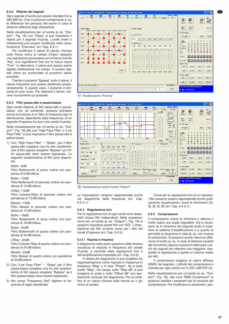
6.5.2 Ritardo dei segnaliOgni segnale dʼuscita può essere ritardato fino a380,998 ms. Così si possono compensare p. es.le differenze nel percorso del suono in caso didistanze differenti degli altoparlanti.
Nella visualizzazione per unʼuscita (p. es. “Out-put1”, Fig. 18) con “Delay” si può impostare ilritardo per il segnale dʼuscita. Lʼunità (metri omillisecondi) può essere modificata nella visua-lizzazione “Overview” (� Cap. 6.3.1).
Per modificare il valore di ritardo, cliccaresulle frecce vicino al campo dʼinput: eseguireuna regolazione grossolana con le frecce tramite“Adj”, una regolazione fine con le frecce sopra“Fine”. In alternativa, il valore può essere anchedigitato direttamente nel campo. Il numero digi-tato viene poi arrotondato al prossimo valorepossibile.
Tramite il pulsante “Bypass” sotto il valore, ilritardo impostato può essere disattivato tempo-raneamente. In questo caso, il pulsante si pre-senta di color rosso. Per riattivare il ritardo, clic-care nuovamente sul pulsante.
6.5.3 Filtri passa-alto e passa-bassoOgni uscita dispone di filtri passa-alto e passa-basso, che, se combinati, possono prendereanche la funzione di un filtro di frequenza (per ladistribuzione, dipendente dalla frequenza, di unsegnale dʼingresso fra due o più canali dʼuscita).
Nella visualizzazione per unʼuscita (p. es. “Out-put1”, Fig. 18) alle voci “High Pass Filter” e “LowPass Filter” si può impostare il filtro passa-alto epassa-basso.
1) Con “High Pass Filter” – “Slope”, per il filtropassa-alto scegliere una fra otto caratteristi-che di filtri oppure scegliere “Bypass” se il fil-tro passa-alto deve essere bypassato. Leseguenti caratteristiche di filtri sono disponi-bili:
Buttw -6dBFiltro Butterworth di primo ordine con pen-denza di 6 dB / ottava
Buttw -12dBFiltro Butterworth di secondo ordine con pen-denza di 12 dB / ottava
LRiley -12dBFiltro Linkwitz-Riley di secondo ordine conpendenza di 12 dB / ottava
Bessel -12dBFiltro Bessel di secondo ordine con pen-denza di 12 dB / ottava
Buttw -18dBFiltro Butterworth di terzo ordine con pen-denza di 18 dB / ottava
Buttw -24dBFiltro Butterworth di quarto ordine con pen-denza di 24 dB / ottava
LRiley -24dBFiltro Linkwitz-Riley di quarto ordine con pen-denza di 24 dB / ottava
Bessel -24dBFiltro Bessel di quarto ordine con pendenzadi 24 dB / ottava
2) Con “Low Pass Filter” – “Slope” per il filtropassa-basso scegliere una fra otto caratteri-stiche di filtri oppure scegliere “Bypass” se ilfiltro passa-basso deve essere bypassato.
3) Nei campi “Frequency [Hz]” digitare la fre-quenza di taglio desiderata.
47
I
Le impostazioni vengono rappresentate anchenel diagramma delle frequenze (� Cap.6.5.4.1).
6.5.4 Regolazione toniPer la regolazione toni di ogni uscita sono dispo-nibili cinque filtri indipendenti. Nella visualizza-zione per unʼuscita (p. es. “Output1”, Fig. 18) sipossono impostare questi filtri con “EQ”. Lʼimpo-stazione dei filtri avviene come per i filtri deicanali dʼingresso (� Cap. 6.4.5).
6.5.4.1 Risposta in frequenzaIl diagramma nella parte superiore della finestravisualizza la risposta in frequenza del canaledʼuscita, a seconda della regolazione toni edellʼamplificazione impostata (� Cap. 6.5.6).
A destra del diagramma si può scegliere frarappresentazione come risposta in frequenza inampiezza “Mag” o in fase “Phase”. Se è statoscelto “Mag”, nel campo sotto “Step dB” si puòscegliere la scala e sotto “Offset dB” uno spo-stamento verticale del diagramma. Per la modi-fica di un valore cliccare sulla freccia su o giùvicino al campo.
Come per la regolazione toni di un ingresso,i filtri possono essere rappresentati anche grafi-camente visualizzando i punti di riferimento ( ,
, , , ) (� Cap. 6.4.5.1).
6.5.5 Compressore
Il compressore riduce la dinamica e attenua illivello sopra una soglia regolabile. Ciò è neces-sario se la dinamica del segnale audio è supe-riore al sistema dʼamplificazione e a quanto lopermette la situazione in sala (p. es. con musicadi sottofondo). Si possono anche ridurre le diffe-renze di livello (p. es. in caso di distanze variabilidal microfono) oppure si possono attenuare i pic-chi dei segnali per ottenere una maggiore pos-sibilità di regolazione e quindi un volume mediopiù alto.
Il compressore reagisce al valore efficace(RMS) del segnale. Lʼattività del compressore èindicata per ogni uscita con il LED LIMITER (4).
Nella visualizzazione per unʼuscita (p. es. “Out-put1”, Fig. 18), alla voce “RMS Compressor” sipossono stabilire i parametri per la funzione delcompressore. Per modificare un parametro, spo-
⑰ Visualizzazione “Routing”
⑱ Visualizzazione canali dʼuscita “Output1”
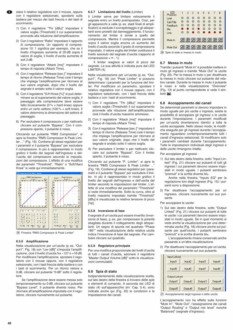
stare il relativo regolatore con il mouse, oppurecon il regolatore selezionato, spostarlo sullatastiera per mezzo dei tasti freccia o dei tasti discorrimento.
1) Con il regolatore “Thr [dBu]” impostare ilvalore soglia (Threshold) il cui superamentoprovvede alla riduzione dellʼamplificazione.
2) Con il regolatore “Ratio” impostare il rapportodi compressione. Un rapporto di compres-sione 10 : 1 significa per esempio, che se illivello dʼingresso aumenta di 20 dB sopra ilvalore di soglia, il livello dʼuscita aumenta disoli 2 dB.
3) Con il regolatore “Attack [ms]” impostare iltempo di risposta (Attack Time).
4) Con il regolatore “Release [sec.]” impostare iltempo di ritorno (Release Time) cioè il tempoche impiega lʼamplificazione per ritornare alsuo valore originale, dopo che il livello delsegnale è andato sotto il valore soglia.
5) Con il regolatore “S / H Knee [%]” si può deter-minare se al superamento del valore soglia, ilpassaggio alla compressione deve esserefatto bruscamente (0 % = hard knee) oppureentro un certo settore (100 % = soft knee). Ilvalore determina la dimensione del settore dipassaggio.
6) Per escludere il compressore o per riattivarlocliccare sul pulsante “Bypass”. Con il com-pressore spento, il pulsante è rosso.
Cliccando sul pulsante “RMS Compressor”, siapre la finestra “RMS Compressor & Peak Limi-ter ...” (Fig. 19). Contiene gli stessi regolatori peri parametri e il pulsante “Bypass” per escludereil compressore. In più è rappresentato in modografico il livello dei segnali dellʼingresso e del-lʼuscita del compressore secondo le imposta-zioni del compressore. Lʼeffetto di una modificadei parametri “Threshold”, “Ratio” o “Soft / HardKnee” si vede qui immediatamente.
6.5.6 AmplificazioneNella visualizzazione per unʼuscita (p. es. “Out-put1”, Fig. 18) con “Lev [dB]” sʼimposta lʼamplifi-cazione, cioè il livello dʼuscita fra -127 e +18 dB.Per modificare lʼamplificazione, spostare il rego-latore con il mouse oppure, con il regolatoreselezionato, con i tasti freccia della tastiera o coni tasti di scorrimento. Per un ritorno veloce a0 dB, cliccare sul pulsante “0 dB” sotto il regola-tore.
Se lʼamplificazione deve essere messa solotemporaneamente su 0 dB, cliccare sul pulsante“Bypass Level”. Il pulsante diventa rosso. Perritornare allʼamplificazione impostata con il rego-latore, cliccare nuovamente sul pulsante.
6.5.7 Limitazione del livello (Limiter)
Il Limiter serve per limitare velocemente ilsegnale entro un livello preimpostato. Così, pergli apparecchi a valle (p. es. stadi finali di ampli-ficatori) si esclude il sovrapilotaggio e gli altopar-lanti sono protetti dal danneggiamento. Il funzio-namento del limiter è simile a quello delcompressore. Mentre il compressore permettesopra il valore soglia ancora un aumento dellivello dʼuscita secondo il grado di compressioneimpostato, il valore soglia del limiter costituisce illivello assoluto del segnale dʼuscita (rapporto dicompressione = ∞ : 1).
Il limiter reagisce ai valori di picco delsegnale. La sua attività è indicata pure dal LEDLIMITER (4).
Nella visualizzazione per unʼuscita (p. es. “Out-put1”, Fig. 18) con “Peak Limiter” si possonodeterminare i parametri per la funzione del limi-ter. Per modificare un parametro, spostare ilrelativo regolatore con il mouse oppure, con ilregolatore selezionato, con i tasti freccia dellatastiera o con i tasti di scorrimento.
1) Con il regolatore “Thr [dBu]” impostare ilvalore soglia (Threshold) il cui superamentoprovvede alla riduzione dellʼamplificazione,cioè il livello dʼuscita massimo ammesso.
2) Con il regolatore “Attack [ms]” impostare iltempo di risposta (Attack Time).
3) Con il regolatore “Release [sec.]” impostare iltempo di ritorno (Release Time) cioè il tempoche impiega lʼamplificazione per ritornare alsuo valore originale, dopo che il livello delsegnale è andato sotto il valore soglia.
4) Per escludere il limiter o per riattivarlo clic-care sul pulsante “Bypass”. Con il limiterspento, il pulsante è rosso.
Cliccando sul pulsante “P. Limiter”, si apre lafinestra “RMS Compressor & Peak Limiter ...”(Fig. 19). Contiene gli stessi regolatori per i para-metri e il pulsante “Bypass” per escludere il limi-ter. In più è rappresentato in modo grafico illivello dei segnali dellʼingresso e dellʼuscita dellimiter secondo le impostazioni del limiter. Lʼef-fetto di una modifica del parametro “Threshold”si vede immediatamente. Sotto la curva, oltre allivello massimo impostato tramite “Threshold”[dBu] è visualizzata la relativa tensione di picco[Vp].
6.5.8 Inversione di faseIl segnale di unʼuscita può essere invertito (inver-sione di fase), p. es. per compensare la polaritàsbagliata durante il collegamento degli altopar-lanti. Un segno di spunta nel quadrato “Phase180°” nella visualizzazione della relativa uscitaindica lʼinversione di fase del segnale. Per cam-biare cliccare sul quadrato.
6.5.9 Regolatore principalePer una modifica proporzionale dei livelli dʼuscitadi tutti i canali dʼuscita, azionare il regolatore“Master Output Volume [dB]” sotto le visualizza-zioni commutabili.
6.6 Spia di statoIndipendentemente dalla visualizzazione scelta,sul lato destro della finestra si trovano delle spiee elementi di comando. A seconda dei LED distato (4) sullʼapparecchio (� Cap. 5.4), sonoindicate anche qui (Fig. 20) le condizioni e leimpostazione dei canali.
6.7 Messa in mutoTramite i pulsanti “Mute In” è possibile mettere inmuto gli ingressi e tramite “Mute Out” le uscite(Fig. 20). Per la messa in muto o per disattivarela messa in muto cliccare sul pulsante del rela-tivo canale. Durante la messa in muto il pulsanteè rosso e nella visualizzazione “Overview”(Fig. 13) al punto corrispondente si vede il sim-bolo .
6.8 Accoppiamento dei canaliSe determinati parametri si devono impostare inmodo uguale per più uscite o ingressi, esiste lapossibilità di accoppiare gli ingressi o le uscitedurante lʻimpostazione. I parametri modificatiper unʼuscita diventeranno identici a tutte leuscite accoppiate. Nello stesso modo, le modifi-che eseguite per gli ingressi durante lʼaccoppia-mento riguardano contemporaneamente tutti icanali dʼingresso selezionati. Si modificano soloi parametri cambiati durante lʼaccoppiamento.Tutte le impostazioni individuali degli ingressi edelle uscite rimangono intatte.
Per accoppiare gli ingressi :
1) Sul lato destro della finestra, sotto “Input Lin-ked” (Fig. 21) cliccare sui pulsanti di tutti gliingressi i cui parametri devono essere impo-stati in modo uguale. I pulsanti sembrano“premuti” e la scritta diventa blu.
Anche nella finestra “Inputs EQ” per laregolazione toni degli ingressi (Fig. 15) i pul-santi sono a disposizione.
2) Per disattivare lʼaccoppiamento per uningresso, cliccare nuovamente sul suo pul-sante.
Per accoppiare le uscite:
1) Sul lato destro della finestra, sotto “OutputLinked” (Fig. 21) cliccare sui pulsanti di tuttele uscite i cui parametri devono essere impo-stati in modo uguale. Se in quel momento sivede anche la visualizzazione per una deter-minata uscita (Fig. 18) cliccare anche sul pul-sante per quell'uscita. I pulsanti sembrano“premuti” e la scritta diventa blu.
Lʼaccoppiamento rimane conservato anchepassando a unʼaltra visualizzazione.
2) Per disattivare lʼaccoppiamento per unʼuscita,cliccare nuovamente sul suo pulsante.
Lʼaccoppiamento non ha effetto sulle funzioni“Mute In”, “Mute Out”, lʼassegnazione dei canali“Output Routing” e “Output mix level” nonché“Balanced” (segnale dʼingresso).
㉑ Accoppiamento degli ingressi e delle uscite
⑳ Spie di stato e messa in muto
⑲ Finestra “RMS Compressor & Peak Limiter”
48
I
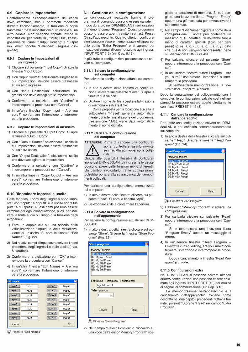
6.9 Copiare le impostazioniContrariamente allʼaccoppiamento dei canalidove cambiano solo i parametri modificatidurante lʼaccoppiamento, la funzione di copiatrasmette tutte le impostazioni di un canale su unaltro canale. Non vengono copiate invece leimpostazioni per “Mute In”, “Mute Out”, lʼasse-gnazione dei canali “Output Routing” e “Outputmix level” nonché “Balanced” (segnale dʼin-gresso).
6.9.1 Copiare le impostazioni di un ingresso
1) Cliccare sul pulsante “Input Copy”. Si apre lafinestra “Input Copy”.
2) Con “Input Source” selezionare lʼingresso lecui impostazioni devono essere trasmessesu un altro ingresso.
3) Con “Input Destination” selezionare lʼin-gresso che deve accogliere le impostazioni.
4) Confermare la selezione con “Confirm” ointerrompere la procedura con “Cancel”.
5) In unʼaltra finestra “Copy Input – Are yousure?” confermare lʼintenzione o interrom-pere la procedura.
6.9.2 Copiare le impostazioni di unʼuscita
1) Cliccare sul pulsante “Output Copy”. Si aprela finestra “Output Copy”.
2) Con “Output Source” selezionare lʼuscita lecui impostazioni devono essere trasmessesu unʼaltra uscita.
3) Con “Output Destination” selezionare lʼuscitache deve accogliere le impostazioni.
4) Confermare la selezione con “Confirm” ointerrompere la procedura con “Cancel”.
5) In unʼaltra finestra “Copy Output – Are yousure?” confermare lʼintenzione o interrom-pere la procedura.
6.10 Rinominare ingressi e usciteDalla fabbrica, i nomi degli ingressi sono impo-stati con “Input1” a “Input8” e le uscite con “Out-put 1” a “Output8”. Questi nomi possono esserecambiati per ogni configurazione, p. es. per indi-care la fonte audio o il luogo o la funzione deglialtoparlanti.
1) Fare un doppio clic su una scheda dellavisualizzazione “Inputs” o della visualizza-zione di unʼuscita. Si apre la finestra “EditNames” (Fig. 22).
2) Nei relativi campi dʼinput sovrascrivere i nomiprecedenti degli ingressi o delle uscite (max.8 caratteri).
3) Confermare la digitazione con “OK” o inter-rompere la procedura con “Cancel”.
4) In unʼaltra finestra “Edit Names – Are yousure?” confermare lʼintenzione o interrom-pere la procedura.
6.11 Gestione della configurazioneLe configurazioni realizzate tramite il pro-gramma di comando possono essere salvate inmodo duraturo nel DRM-880LAN in sei locazionidi memoria come “Program”. Questi programmipossono essere aperti tramite i sei tasti Preset(3) sullʼapparecchio. Quattro ulteriori configura-zioni possono essere memorizzate nellʼapparec-chio come “Extra Program” e si aprono permezzo dei segnali di commutazione agli ingressiINPUT PORT (13) (� Cap. 6.13).
In più, tutte le configurazioni possono essere sal-vate sul computer.
6.11.1 Salvare la configurazione sul computer
Per salvare la configurazione attuale sul compu-ter:
1) In alto a destra della finestra di configura-zione, cliccare sul pulsante “Save”. Si apre lafinestra “Salva con”.
2) Digitare il nome del file, scegliere la locazionedi memoria e salvare il file.
Come proposta per la locazione è scelta lasottocartella “Preset” generata automatica-mente durante lʼinstallazione del programma.Lʼestensione *.M88 viene data automatica-mente al nome digitato.
6.11.2 Caricare la configurazione dal computer
Per caricare una configurazione memorizzatasul computer:
1) In alto a destra della finestra cliccare sul pul-sante “Load”. Si apre la finestra “Apri”.
2) Selezionare il file e confermare lʻapertura.
6.11.3 Salvare la configurazionenellʻapparecchio
Per salvare la configurazione attuale nel DRM-880LAN:
1) In alto a destra della finestra cliccare sul pul-sante “Store”. Si apre la finestra “Store Pro-gram” (Fig. 23).
2) Nel campo “Select Position” o cliccando suuna voce dellʼelenco “Memory Program” sce-
gliere la locazione di memoria. Si può sce-gliere una locazione libera “Program Empty”oppure una già occupata per sovrascrivere ilsuo contenuto.
3) Nel campo “Edit Name” digitare il nome dellaconfigurazione. Il nome può contenere unmassimo di 16 caratteri. Si dovrebbe fare ameno di caratteri speciali (tipici per certipaesi) (p. es. ä, ö, ü, ß, è, ô, ì, á, ñ, μ) datoche questi non vengono rappresentati benesul display del DRM-880LAN.
4) Per salvare, cliccare sul pulsante “Store”oppure interrompere la procedura con “Can-cel”.
5) In unʼulteriore finestra “Store Program – Areyou sure?” confermare lʼintenzione o inter-rompere la procedura.
Al termine della memorizzazione, la fine-stra “Store Program” si chiude.
Dopo la separazione del collegamento con ilcomputer, le configurazioni salvate così nellʼap-parecchio possono essere aperte direttamentecon i tasti PRESET 1 – 6 (3).
6.11.4 Caricare la configurazionedallʻapparecchio
Per aprire una configurazione salvata nel DRM-880LAN e per caricarla contemporaneamentesul computer:
1) In alto a destra della finestra cliccare sul pul-sante “Read”. Si apre la finestra “Read Pro-gram” (Fig. 24).
2) Dallʼelenco “Memory Program” scegliere unaconfigurazione.
3) Per caricarla cliccare sul pulsante “Read”oppure interrompere la procedura con “Can-cel”.
Se è stata scelta una locazione libera“Program Empty” appare un messaggio dierrore.
4) In unʼulteriore finestra “Read Program –Overwrite current editing, are you sure?” con-fermare lʼintenzione o interrompere la proce-dura.
Dopo il caricamento la finestra “Read Pro-gram” si chiude.
6.11.5 Configurazioni extraNel DRM-880LAN si possono salvare ulterioriquattro configurazioni che possono essere chia-mate agli ingressi INPUT PORT (13) per mezzodi segnali di commutazione (� Cap. 6.13).
La memorizzazione nellʼapparecchio e ilcaricamento dallʼapparecchio avviene comedescritto nei due capitoli precedenti, tuttavia tra-mite i pulsanti “Store” e “Read” nel campo “ExtraProgram”.
㉔ Finestra “Read Program”
㉓ Finestra “Store Program”
㉒ Finestra “Edit Names”
ATTENZIONE Prima di caricare una configura-zione controllare assolutamentese si adatta agli apparecchi colle-gati.
Grazie alle possibilità flessibili di configura-zione del DRM-880LAN, gli ingressi e le uscitepossono avere delle funzioni molto differenti.Un cambio involontario fra le configurazionipotrebbe portare alla sovraccarica dei compo-nenti collegati.
49
I
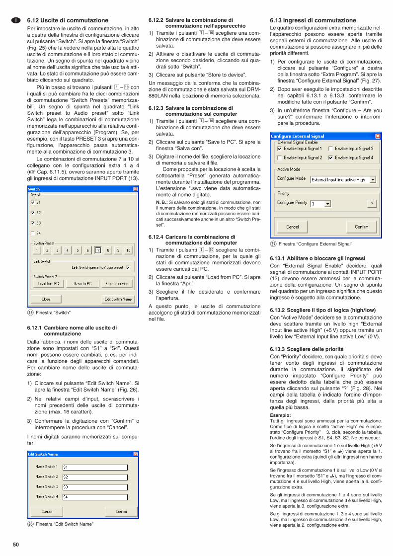
6.12 Uscite di commutazionePer impostare le uscite di commutazione, in altoa destra della finestra di configurazione cliccaresul pulsante “Switch”. Si apre la finestra “Switch”(Fig. 25) che fa vedere nella parte alta le quattrouscite di commutazione e il loro stato di commu-tazione. Un segno di spunta nel quadrato vicinoal nome dellʼuscita significa che tale uscita è atti-vata. Lo stato di commutazione può essere cam-biato cliccando sul quadrato.
Più in basso si trovano i pulsanti 1 – 10 coni quali si può cambiare fra le dieci combinazionidi commutazione “Switch Presets” memorizza-bili. Un segno di spunta nel quadrato “LinkSwitch preset to Audio preset” sotto “LinkSwitch” lega le combinazioni di commutazionememorizzate nellʼapparecchio alla relativa confi-gurazione dellʼapparecchio (Program). Se, peresempio, con il tasto PRESET 3 si apre una con-figurazione, lʼapparecchio passa automatica-mente alla combinazione di commutazione 3.
Le combinazioni di commutazione 7 a 10 sicollegano con le configurazioni extra 1 a 4(� Cap. 6.11.5), ovvero saranno aperte tramitegli ingressi di commutazione INPUT PORT (13).
6.12.1 Cambiare nome alle uscite dicommutazione
Dalla fabbrica, i nomi delle uscite di commuta-zione sono impostati con “S1” a “S4”. Questinomi possono essere cambiati, p. es. per indi-care la funzione degli apparecchi comandati.Per cambiare nome delle uscite di commuta-zione:
1) Cliccare sul pulsante “Edit Switch Name”. Siapre la finestra “Edit Switch Name” (Fig. 26).
2) Nei relativi campi dʼinput, sovrascrivere inomi precedenti delle uscite di commuta-zione (max. 16 caratteri).
3) Confermare la digitazione con “Confirm” ointerrompere la procedura con “Cancel”.
I nomi digitati saranno memorizzati sul compu-ter.
6.12.2 Salvare la combinazione dicommutazione nellʻapparecchio
1) Tramite i pulsanti 1 – 10 scegliere una com-binazione di commutazione che deve esseresalvata.
2) Attivare o disattivare le uscite di commuta-zione secondo desiderio, cliccando sui qua-drati sotto “Switch”.
3) Cliccare sul pulsante “Store to device”.
Un messaggio dà la conferma che la combina-zione di commutazione è stata salvata sul DRM-880LAN nella locazione di memoria selezionata.
6.12.3 Salvare la combinazione dicommutazione sul computer
1) Tramite i pulsanti 1 – 10 scegliere una com-binazione di commutazione che deve esseresalvata.
2) Cliccare sul pulsante “Save to PC”. Si apre lafinestra “Salva con”.
3) Digitare il nome del file, scegliere la locazionedi memoria e salvare il file.
Come proposta per la locazione è scelta lasottocartella “Preset” generata automatica-mente durante lʼinstallazione del programma.Lʼestensione *.swc viene data automatica-mente al nome digitato.N. B.: Si salvano solo gli stati di commutazione, nonil numero della combinazione, in modo che gli statidi commutazione memorizzati possono essere cari-cati successivamente anche in un altro “Switch Pre-set”.
6.12.4 Caricare la combinazione dicommutazione dal computer
1) Tramite i pulsanti 1 – 10 scegliere la combi-nazione di commutazione, per la quale glistati di commutazione memorizzati devonoessere caricati dal PC.
2) Cliccare sul pulsante “Load from PC”. Si aprela finestra “Apri”.
3) Scegliere il file desiderato e confermarelʻapertura.
A questo punto, le uscite di commutazioneaccolgono gli stati di commutazione memorizzatinel file.
6.13 Ingressi di commutazioneLe quattro configurazioni extra memorizzate nel-lʼapparecchio possono essere aperte tramitesegnali esterni di commutazione. Alle uscite dicommutazione si possono assegnare in più dellepriorità differenti.
1) Per configurare le uscite di commutazione,cliccare sul pulsante “Configure” a destradella finestra sotto “Extra Program”. Si apre lafinestra “Configure External Signal” (Fig. 27).
2) Dopo aver eseguito le impostazioni descrittenei capitoli 6.13.1 a 6.13.3, confermare lemodifiche fatte con il pulsante “Confirm”.
3) In unʼulteriroe finestra “Configure – Are yousure?” confermare lʼintenzione o interrom-pere la procedura.
6.13.1 Abilitare o bloccare gli ingressiCon “External Signal Enable” decidere, qualisegnali di commutazione ai contatti INPUT PORT(13) devono essere ammessi per la commuta-zione della configurazione. Un segno di spuntanel quadrato per un ingresso significa che questoingresso è soggetto alla commutazione.
6.13.2 Scegliere il tipo di logica (high / low)Con “Active Mode” decidere se la commutazionedeve scattare tramite un livello high “ExternalInput line active High” (+5 V) oppure tramite unlivello low “External Input line active Low” (0 V).
6.13.3 Scegliere delle prioritàCon “Priority” decidere, con quale priorità si devetener conto degli ingressi di commutazionedurante la commutazione. Il significato delnumero impostato “Configure Priority” puòessere dedotto dalla tabella che può essereaperta cliccando sul pulsante “?” (Fig. 28). Neicampi della tabella è indicato lʼordine dʼimpor-tanza degli ingressi, dalla priorità più alta aquella più bassa.
Esempio:Tutti gli ingressi sono ammessi per la commutazione.Come tipo di logica è scelto “active High” ed è impo-stato “Configure Priority” = 3, cioè, secondo la tabella,lʼordine degli ingressi è S1, S4, S3, S2. Ne consegue:
Se lʼingresso di commutazione 1 è sul livello High (+5 Vsi trovano fra il morsetto “S1” e ) viene aperta la 1.configurazione extra (quindi gli altri ingressi non hannoimportanza).
Se lʼingresso di commutazione 1 è sul livello Low (0 V sitrovano fra il morsetto “S1” e ), ma lʼingresso di com-mutazione 4 è sul livello High, viene aperta la 4. confi-gurazione extra.
Se gli ingressi di commutazione 1 e 4 sono sul livelloLow, ma lʼingresso di commutazione 3 è sul livello High,viene aperta la 3. configurazione extra.
Se gli ingressi di commutazione 1, 3 e 4 sono sul livelloLow, ma lʼingresso di commutazione 2 e sul livello High,viene aperta la 2. configurazione extra.
㉗ Finestra “Configure External Signal”
㉖ Finestra “Edit Switch Name”
㉕ Finestra “Switch”
50
I
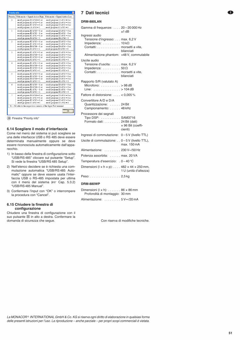
6.14 Scegliere il modo dʻinterfacciaCome nel menù del sistema si può scegliere seuna delle interfacce USB o RS 485 deve esseredeterminata manualmente oppure se deveessere riconosciuta automaticamente dallʻappa-recchio.
1) In basso della finestra di configurazione sotto“USB/ RS 485” cliccare sul pulsante “Setup”.Si vede la finestra “USB/ RS 485 Setup”.
2) Nellʼelenco decidere se è richiesta una com-mutazione automatica “USB/ RS 485 Auto-matic” oppure se deve essere usata lʼinter-faccia USB o RS-485 impostata per ultimacon il menù del sistema (� Cap. 5.3.2)“USB/ RS 485 Manual”.
3) Confermare lʼinput con “OK” o interromperela procedura con “Cancel”.
6.15 Chiudere la finestra diconfigurazione
Chiudere una finestra di configurazione con ilsuo pulsante ⊠ in alto a destra. Confermare ladomanda di sicurezza che segue.
7 Dati tecnici
DRM-880LAN
Gamma di frequenze: . . . . 20 – 20 000 Hz ±1 dB
Ingressi audioTensione dʻingresso: . . . max. 6,2 VImpedenza: . . . . . . . . . . 10 kΩContatti: . . . . . . . . . . . . . morsetti a vite,
bilanciatiAlimentazione phantom: +48 V, commutabile
Uscite audioTensione dʻuscita: . . . . . max. 6,2 VImpedenza: . . . . . . . . . . 50 ΩContatti: . . . . . . . . . . . . . morsetti a vite,
bilanciati
Rapporto S/R (valutato A)Microfono: . . . . . . . . . . . > 98 dBLine: . . . . . . . . . . . . . . . > 104 dB
Fattore di distorsione: . . . . < 0,005 %
Convertitore A / D e D /AQuantizzazione: . . . . . . 24 BitCampionamento: . . . . . . 48 kHz
Processore dei segnaliTipo DSP: . . . . . . . . . . . SAM3716Formato dati: . . . . . . . . . 24 Bit (dati)
× 96 Bit (coeffi-cienti)
Ingressi di commutazione: 0 – 5 V (livello TTL)
Uscite di commutazione: . . 0 – 5 V (livello TTL),max. 150 mA
Alimentazione: . . . . . . . . . 230 V~ / 50 Hz
Potenza assorbita: . . . . . . max. 20 VA
Temperatura dʻesercizio: . 0 – 40 °C
Dimensioni (l × h × p): . . . . 482 × 44 × 250 mm,1 U (unità dʻaltezza)
Peso: . . . . . . . . . . . . . . . . . 2,5 kg
DRM-880WP
Dimensioni (l × h): . . . . . . . 86 × 86 mmProfondità di montaggio: 30 mm
Alimentazione: . . . . . . . . . 5 V�/ 20 mA
Con riserva di modifiche tecniche.
㉘ Finestra “Priority info”
51
I
La MONACOR ® INTERNATIONAL GmbH & Co. KG si riserva ogni diritto di elaborazione in qualsiasi formadelle presenti istruzioni per lʼuso. La riproduzione – anche parziale – per propri scopi commerciali è vietata.
52
Por favor, antes del uso del aparato ob servar entodo caso los consejos de seguridad siguientes.Si informaciones ad icionales son necesariaspara la operación del aparato, estas se encuen-tran en los otros idiomas de estas instrucciones.
Consejos de SeguridadEl aparato cumple con todas las directivas rele-vantes de la UE y por lo tanto está marcado conel símbolo .
Es imprescindible que preste atención a los pun-tos siguientes:
� El aparato está adecuado para su utilizaciónsólo en interiores. Protéjalo de goteos y salpi-caduras, elevada humedad del aire y calor(temperatura ambiente admisible: 0 – 40 ºC).
� No coloque ningún recipiente lleno de líquidoencima del aparato, como por ejemplo unvaso.
� El calor que se genera en el aparato tiene queexpulsarse mediante la circulación del aire.Así pues, las rejillas de ventilación no debenobstruirse.
� No ponga el aparato en funcionamiento y des-conecte inmediatamente el enchufe de latoma de corriente si:1. Existe algún daño visible en el aparato o en
el cable de corriente.2. Aparece algún defecto por caída o acci-
dente similar.3. No funciona correctamente.Sólo el personal cualificado puede reparar elaparato bajo cualquier circunstancia.
� No tire nunca del cable de corriente para des-conectar el enchufe de la toma de corriente,tire siempre del enchufe.
� Utilice sólo un paño suave y seco para la lim-pieza, no utilice nunca ni productos químicosni agua.
� No podrá reclamarse garantía o responsabili-dad alguna por cualquier daño personal omaterial resultante si el aparato se utiliza paraotros fines diferentes a los originalmente con-cebidos, si no se conecta o se utiliza adecua-damente o no se repara por expertos. Delmismo modo, no se aceptará ninguna respon-sabilidad por la pérdida de datos provocadapor un defecto o por los daños a consecuen-cia de esta pérdida de datos.
Si va a poner el aparato fuera de serviciodefinitivamente, llévelo a la planta de reci-claje de la zona para que su eliminaciónno sea perjudicial para el medio ambiente.
ADVERTENCIA El aparato está alimentado conun voltaje peligroso. Deje elmantenimiento en manos delpersonal cualificado. No insertenada a través de las rejillas deventilación. El manejo inex-perto o la modificación del apa-rato pueden provocar una des-carga.
E
Lees aandachtig de onderstaande veiligheids-voorschriften, alvorens het toestel in gebruik tene men. Mocht u bijkomende informatie over debediening van het toestel nodig hebben, leesdan de En gelse tekst van deze hand lei ding.
VeiligheidsvoorschriftenDit apparaat is in overeenstemming met alle ver-eiste EU-Richtlijnen en is daarom met geken-merkt.
Let eveneens op het volgende:
� Het apparaat is enkel geschikt voor gebruikbinnenshuis; vermijd druip- en spatwater,plaatsen met een hoge vochtigheid en uitzon-derlijk warme plaatsen (toegestaan omge-vingstemperatuurbereik: 0 – 40 °C).
� Plaats geen bekers met vloeistof zoals drink-glazen etc. op het apparaat.
� De warmte die in het toestel ontstaat, moetdoor ventilatie worden afgevoerd. Dek daar -om de ventilatieopeningen van de behuizingniet af.
� Schakel het apparaat niet in resp. trek onmid-dellijk de stekker uit het stopcontact,1. wanneer het apparaat of het netsnoer zicht-
baar beschadigd is,
2. wanneer er een defect zou kunnen optre-den nadat het apparaat bijvoorbeeld isgevallen,
3. wanneer het apparaat slecht functioneert.Het apparaat moet in elk geval worden her-steld door een gekwalificeerd vakman.
� Trek de stekker nooit met het snoer uit hetstopcontact, maar met de stekker zelf.
� Verwijder het stof met een droge, zachtedoek. Gebruik zeker geen water of chemica-liën.
� In geval van ongeoorloofd of verkeerd ge -bruik, verkeerde aansluiting, foutieve bedie-ning of van herstelling door een niet-gekwalifi-ceerd persoon vervalt de garantie en deverantwoordelijkheid voor hieruit resulterendemateriële of lichamelijke schade. Zo kunnenwij ook niet aansprakelijkheid worden gesteldvoor gegevensverliezen als gevolg van fou-tieve bediening of een defect, noch voor deschade die hieruit volgt.
Wanneer het apparaat definitief uit be -drijf wordt genomen, bezorg het danvoor milieuvriendelijke verwerking aaneen plaatselijk recyclagebedrijf.
WAARSCHUWING De netspanning van de ap -paraat is levensgevaarlijk.Open het apparaat niet, enzorg dat u niets in de venti-latieopeningen steekt! U loopt het risico van eenelektrische schok.
NL
B
53
Przed użyciem urządzenia należy przeczytaćuważnie poniższą instrukcję obsługi i zachowaćtekst do wglądu. Więcej informacji dotyczącychobsługi urządzenia znajduje się w innych wers-jach językowych niniejszej instrukcji obsługi.
Środki bezpieczeństwaUrządzenie spełnia wymogi norm obowiązują-cych w Unii Europejskiej, oznaczone zostałowięc symbolem .
Należy przestrzegać następujących zasad:
� Urządzenie przeznaczone jest do użytku wpomieszczeniach zamkniętych. Należy chro-nić je przed bezpośrednim kontaktem z wodą,działaniem wilgoci oraz wysokiej temperatury(zakres dopuszczalnej temperatury otoczeniapracy wynosi od 0 do 40 °C).
� Na obudowie urządzenia nie wolno stawiaćpojemników z płynem (np. szklanek).
� Należy zapewnić swobodną cyrkulacjępowietrza, aby zapobiec przegrzaniu. Nie
wolno zasłaniać otworów wentylacyjnych wobudowie urządzenia.
� Należy przerwać użytkowanie urządzeniaoraz niezwłocznie wyjąć wtyczkę zasilania zgniazda jeśli: 1. nastąpiło widoczne uszkodzenie urządze-
nia lub kabla zasilającego,2. mogło nastąpić uszkodzenie urządzenia
np. na skutek jego upuszczenia,3. urządzenie działa nieprawidłowo.Wszelkie naprawy należy zlecić specjaliście.
� Nie wolno odłączać urządzenia z gniazda sie-ciowego ciągnąc za kabel zasilania - należyzawsze chwytać za wtyczkę.
� Do czyszczenia urządzenia należy używaćsuchej, miękkiej tkaniny. Nie wolno stosowaćwody ani chemicznych środków czyszczą-cych.
� Producent ani dostawca nie ponoszą odpo-wiedzialności za wynikłe szkody: uszkodzeniesprzętu lub obrażenia użytkownika, jeśli urzą-dzenie było używane niezgodnie z ich prze-znaczeniem, nieprawidłowo zamontowane,podłączone lub obsługiwane bądź poddanenieautoryzowanej naprawie. Producent orazdostawca nie ponoszą również odpowiedzial-
ności za błędną obsługę, utratę danych wwyniku usterki, a także za szkody wynikającez utraty danych.
Po całkowitym zakończeniu eksploata-cji urządzenia należy przekazać je dopunktu utylizacji odpadów, aby uniknąćzanieczyszczenia środowiska.
OSTRZEŻENIE Urządzenie jest zasilane napię-ciem sieciowym, które stanowipotencjalne zagrożenie dla użyt-kownika. Naprawę urządzenianależy zlecić specjaliście. Niewolno zakrywać otworów wenty-lacyjnych. Nieostrożne obcho-dzenie się z urządzeniem lubzmiana połączeń mogą spowo-dować porażenie prądem elek-trycznym.
Læs nedenstående sikkerhedsoplysninger grun-digt igennem før ibrugtagning af enheden. Bort-set fra sikkerhedsoplysningerne henvises til denengelske tekst.
Vigtige sikkerhedsoplysningerDenne enhed overholder alle nødvendige EU-direktiver og er som følge deraf mærket .
Vær altid opmærksom på følgende:
� Enheden er kun beregnet til indendørs brug.Beskyt den mod vanddråber og -stænk, højluftfugtighed og varme (tilladt omgivelsestem-peratur 0 – 40 °C).
� Undgå at placere væskefyldte genstande,som f. eks. glas, ovenpå enheden.
� Varmen, der udvikles i enheden, skal kunneslippe ud ved hjælp af luftcirkulation. Kabinet-tets ventilationshuller må derfor aldrig tildæk-kes.
� Tag ikke enheden i brug og tag straks stikketud af stikkontakten i følgende tilfælde:1. hvis der er synlig skade på enheden eller
netkablet.2. hvis der kan være opstået skade, efter at
enheden er tabt eller lignende.3. hvis der forekommer fejlfunktion.
Enheden skal altid repareres af autoriseretpersonel.
� Tag aldrig netstikket ud af stikkontakten ved attrække i kablet, tag fat i selve stikket.
� Til rengøring må kun benyttes en tør, blødklud; der må under ingen omstændighederbenyttes kemikalier eller vand.
� Hvis enheden benyttes til andre formål, endden oprindeligt er beregnet til, hvis den ikke erkorrekt tilsluttet, hvis den betjenes forkert,eller hvis den ikke repareres af autoriseretpersonel, omfattes eventuelle skader ikke afgarantien. Der ydes ingen garanti ved betje-ningsfejl eller tab af data som følge af endefekt i enheden og for den skade dette data-tab vil udgøre.
Hvis enheden skal tages ud af drift forbestandigt, skal den bringes til en lokalgenbrugsstation for bortskaffelse.
ADVARSEL Dette produkt benytter 230 V~.Udfør aldrig nogen form for modi-fikationer på produktet og indføraldrig genstande i ventilationshul-lerne, da du dermed risikere at fåelektrisk stød.
PL
DK
Läs igenom säkerhetsföreskrifterna innan enhe-ten tas i bruk. Ytterligare information återfinns påövriga språk i manualen.
SäkerhetsföreskrifterEnheten uppfyller samtliga Eu-direktiv och hardärför försett med symbolen .
Ge ovillkorligen även akt på följande:
� Enheten är endast avsedd för inomhusbruk.Skyd da enheten mot vätskor, hög luftfuktighetoch hög värme (tillåten omgivningstemperatur0 – 40 °C).
� Placera inte föremål innehållande vätskor,t. ex. dricksglas, på enheten.
� Värmen som alstras skall ledas bort genomcirkulation. Täck därför aldrig över hålen ichassiet.
� Använd inte enheten och tag omedelbart utkontakten ur eluttaget om något av följandeuppstår:1. Enheten eller elsladden har synliga skador.2. Enheten är skadad av fall e. d.3. Enheten har andra felfunktioner.Enheten skall alltid lagas av kunnig personal.
� Drag aldrig ur kontakten genom att dra i slad-den, utan ta tag i kontaktkroppen.
� Rengör endast med en mjuk och torr trasa,an vänd aldrig kemikalier eller vatten vid ren-göring.
� Om enheten används på annat sätt än somavses, om den inte kopplas in ordentligt, omden används på fel sätt eller inte repareras avauktoriserad personal upphör alla garantier attgäll. I dessa fall tas inget ansvar för uppkom-men skada på person eller materiel. Likasåaccepteras inget ansvar för driftsfel eller fördataförlust orsakad av en defekt och för följds-kador av denna dataförlust.
Om enheten skall kasseras skall denlämnas till återvinning.
VARNING Enheten använder hög spänninginternt (230 V~). Gör inga modifie-ringar i enheten eller stoppa före-mål i ventilhålen. Risk för elskadorföreligger.
54
Ole hyvä ja tutustu seuraaviin ohjeisiin varmis-taaksesi tuotteen turvallisen käytön. Tarvitessasilisätietoja tuotteen käytöstä löydät ne muun kie-lisistä käyttöohjeista.
TurvallisuudestaLaite vastaa kaikkia vaadittuja EU direktiivejä,joten se on varustettu merkinnällä.
Ole hyvä ja huomioi seuraavat seikat:
� Laitteet soveltuvat vain sisätilakäyttöön. Suo-jele niitä kosteudelta, vedeltä ja kuumuudelta(sallittu ympäröivä lämpötila 0 – 40 °C).
� Älä sijoita laitteen päälle mitään nestettä sisäl-tävää, kuten vesilasia tms.
� Laitteessa kehittyvä lämpö poistetaan ilman-vaihdolla. Tämän vuoksi laitteen tuuletusauk-koja ei saa peittää.
� Älä kytke virtaa päälle ja irrota laite välittö-mästi sähköverkosta jos:1. laitteessa on näkyvä vika.2. laite on saattanut vaurioitua pudotuksessa
tai vas taavassa tilanteessa.3. laite toimii väärin.Kaikissa näissä tapauksissa laitteen saa kor-jata vain hyväksytty huolto.
� Älä koskaan irroita verkkoliitintä johdostavetämällä. Vedä aina itse liittimestä.
� Käytä puhdistamiseen pelkästään kuivaa,pehmeää kangasta. Älä käytä kemikaaleja taivettä.
� Laitteen takuu raukeaa, eikä valmistaja, maa-hantuoja tai myyjä ota vastuuta mahdollisista välit tömistä tai välillisistä vahingoista, jos lai-tetta on käytetty muuhun kuin alkuperäiseenkäyttötarkoitukseen, laitet ta on taitamatto-masti käytetty tai kytketty tai jos laitetta onhuollettu muussa kuin valtuutetussa huol-lossa. Myöskään mitään vastuuta mahdolli-sista käyttövirheiden, tai muun vian aiheutta-mista tietohävikeistä tai välillisistä vahingoistaei oteta.
Kun laite poistetaan lopullisesti käy-tösta, vie se paikalliseen kierrätyskes-kukseen jälkikäsittelyä varten.
VAROITUS Tämä laite toimii vaarallisella230 V~ jännitteellä. Älä koskaantee mitään muutoksia laitteeseentaikka asenna mitään ilmanvaihtoaukkoihin, koska siitä saattaa seu-rata sähköisku.
FIN
S

® MONACOR INTERNATIONAL GmbH & Co. KG • Zum Falsch 36 • 28307 Bremen • GermanyCopyright © by MONACOR INTERNATIONAL. All rights reserved. A-1400.99.01.08.2013


![]Matrix Tablet](https://img.pdfslide.org/doc/110x75/577ccf211a28ab9e788ef4c9/matrix-tablet.jpg)