Embed Size (px)
Citation preview
Vorlage erstellt am: 14.01.2010 Erstellt von: RB Änderung am: 18.02.2010 Änd.-Index: 00
Baudisch.SIP DoorModule_manual_current.doc Seite 1 von 112
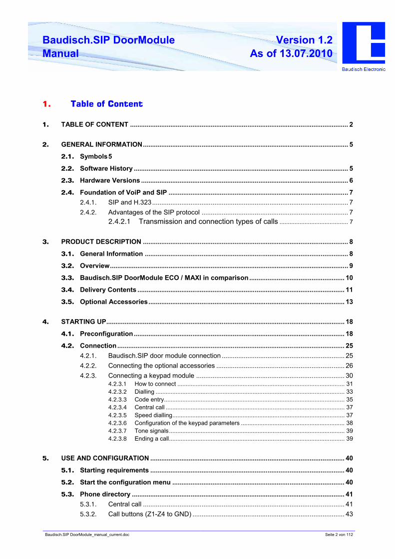
Baudisch.SIP DoorModule MAXI / ECO
Manual
History:
Version Date Name Change
1.0 18.02.2010 R. Bley Regenerated
1.1 07.04.2010 R. Bley Enhancement KeypadModule
1.1 27.04.2010 E. Czeschka English translation
1.2 07.07.2010 M. Bönisch Update
1.2 13.07.2010 U.Meinert Proofreading
Approval latest version:
Date Name Division KZZ Signature
Checked DEV
Checked PF
Checked VT
Checked user
Checked FE
Approved GL
Baudisch.SIP DoorModule_manual_current.doc Seite 2 von 112
Baudisch.SIP DoorModule
Manual
Version 1.2
As of 13.07.2010
1. Table of Content
1. TABLE OF CONTENT ....................................................................................................................... 2
2. GENERAL INFORMATION................................................................................................................ 5
2.1. Symbols5
2.2. Software History ..................................................................................................................... 5
2.3. Hardware Versions ................................................................................................................. 6
2.4. Foundation of VoiP and SIP .................................................................................................. 7
2.4.1. SIP and H.323........................................................................................................... 7
2.4.2. Advantages of the SIP protocol ................................................................................ 7
2.4.2.1 Transmission and connection types of calls ......................................... 7
3. PRODUCT DESCRIPTION ................................................................................................................ 8
3.1. General Information ............................................................................................................... 8
3.2. Overview.................................................................................................................................. 9
3.3. Baudisch.SIP DoorModule ECO / MAXI in comparison.................................................... 10
3.4. Delivery Contents ................................................................................................................. 11
3.5. Optional Accessories........................................................................................................... 13
4. STARTING UP.................................................................................................................................. 18
4.1. Preconfiguration................................................................................................................... 18
4.2. Connection ............................................................................................................................ 25
4.2.1. Baudisch.SIP door module connection ................................................................... 25
4.2.2. Connecting the optional accessories ...................................................................... 26
4.2.3. Connecting a keypad module ................................................................................. 30
4.2.3.1 How to connect .................................................................................................... 31
4.2.3.2 Dialling ................................................................................................................. 33
4.2.3.3 Code entry............................................................................................................ 35
4.2.3.4 Central call ........................................................................................................... 37
4.2.3.5 Speed dialling....................................................................................................... 37
4.2.3.6 Configuration of the keypad parameters .............................................................. 38
4.2.3.7 Tone signals......................................................................................................... 39
4.2.3.8 Ending a call......................................................................................................... 39
5. USE AND CONFIGURATION .......................................................................................................... 40
5.1. Starting requirements .......................................................................................................... 40
5.2. Start the configuration menu .............................................................................................. 40
5.3. Phone directory .................................................................................................................... 41
5.3.1. Central call .............................................................................................................. 41
5.3.2. Call buttons (Z1-Z4 to GND) ................................................................................... 43
Baudisch.SIP DoorModule_manual_current.doc Seite 3 von 112
Baudisch.SIP DoorModule
Manual
Version 1.2
As of 13.07.2010
5.3.3. Call buttons via the matrix module.......................................................................... 44
5.3.3.1 Entries in the call destination lists ........................................................................ 45
5.3.4. Unknown caller........................................................................................................ 46
5.4. VoIP settings......................................................................................................................... 47
5.4.1. Network ................................................................................................................... 48
5.4.2. Language ................................................................................................................ 50
5.4.3. SIP settings ............................................................................................................. 51
5.4.4. Additional SIP settings ............................................................................................ 52
5.4.5. System .................................................................................................................... 54
5.5. Hardware settings ................................................................................................................ 55
5.5.1. Audio ....................................................................................................................... 56
5.5.2. System .................................................................................................................... 58
5.5.3. Call options.............................................................................................................. 60
5.5.4. Status / Remote ...................................................................................................... 63
5.6. Update ................................................................................................................................ 65
5.6.1. Firmware ................................................................................................................. 66
5.7. Reset to factory settings...................................................................................................... 67
6. PRODUCT DETAILS........................................................................................................................ 69
6.1. Technical data....................................................................................................................... 69
6.2. Technical drawings .............................................................................................................. 72
6.2.1. Baudisch.SIP DoorModule MAXI/ECO ................................................................... 72
6.2.2. VA4 front panel ....................................................................................................... 73
6.2.2.1 Installation instructions for V4A front panels ........................................................ 74
6.3. How to connect..................................................................................................................... 75
6.4. Displays ................................................................................................................................ 79
6.4.1. Power supply........................................................................................................... 79
6.4.2. Connections and operating states .......................................................................... 79
6.5. Declaration of conformity .................................................................................................... 81
7. EXTRAS ........................................................................................................................................... 82
7.1. AVR firmware update ........................................................................................................... 82
7.2. EasyLan connection............................................................................................................. 86
7.2.1. General information................................................................................................. 86
7.2.2. Using an EasyLan connection ................................................................................ 86
7.2.3. Baudisch.EasyLan field bus module and functions ................................................ 86
7.2.3.1 Operating per PC or embedded PC via an EasyLan PC interface ....................... 86
7.2.3.2 The connection to the ASB_32InSPS_4OutRelais............................................... 87
7.2.4. Configuration Baudisch.SIP DoorModule MAXI for EasyLan ................................. 87
7.3. Chain operation .................................................................................................................... 88
7.4. Special functions.................................................................................................................. 89
7.4.1. Functions with the configuration parameters .......................................................... 89
Baudisch.SIP DoorModule_manual_current.doc Seite 4 von 112
Baudisch.SIP DoorModule
Manual
Version 1.2
As of 13.07.2010
7.4.1.1 Send a door opening code during a call ............................................................... 89
7.4.1.2 Call logic............................................................................................................... 89
7.4.1.3 Button simulation.................................................................................................. 89
7.4.1.4 Disconnect a call after remote relay ..................................................................... 90
7.4.1.5 Activation of the DTMF relay selection................................................................. 91
7.4.2. Read or write the configuration parameters............................................................ 92
7.5. Status messages .................................................................................................................. 96
7.5.1. Protocol ................................................................................................................... 96
7.5.2. Messages ................................................................................................................ 96
7.6. Remote control ..................................................................................................................... 97
7.6.1. Protocol ................................................................................................................... 97
7.7. Pin strips on the hardware .................................................................................................. 98
7.8. IP Video integration with Baudisch.CP CAM Steel ........................................................... 99
7.8.1. Video display in the web browser ........................................................................... 99
7.8.2. Baudisch.SIP video client........................................................................................ 99
7.8.3. SNOM IP telephone with TFT display................................................................... 100
7.9. Guide for audio settings .................................................................................................... 101
7.10. Create ring tone and announcement message ............................................................... 102
8. FAQ ................................................................................................................................................ 106
9. CUSTOMER SERVICE .................................................................................................................. 108
10. VOCABULARY............................................................................................................................... 109
Baudisch.SIP DoorModule_manual_current.doc Seite 5 von 112
Baudisch.SIP DoorModule
Manual
Version 1.2
As of 13.07.2010
2. General Information
2.1. Symbols
Warning of dangerous electrical voltage.
This symbol points out important references which must be followed to avoid injuries, as well as
damages and malfunctions of the product.
This symbol points out helpful references.
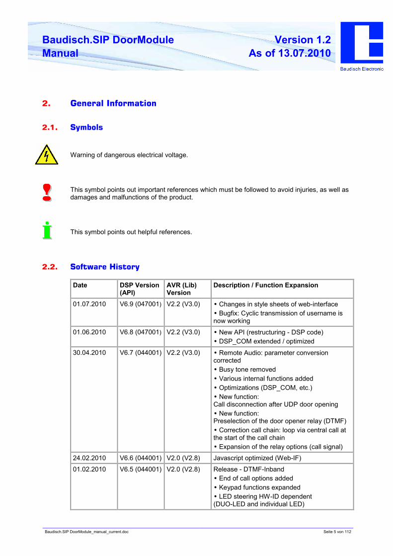
2.2. Software History
Date DSP Version
(API)
AVR (Lib)
Version
Description / Function Expansion
01.07.2010 V6.9 (047001) V2.2 (V3.0) •• Changes in style sheets of web-interface
•• Bugfix: Cyclic transmission of username is
now working
01.06.2010 V6.8 (047001) V2.2 (V3.0) •• New API (restructuring - DSP code)
•• DSP_COM extended / optimized
30.04.2010 V6.7 (044001) V2.2 (V3.0) •• Remote Audio: parameter conversion
corrected
•• Busy tone removed
•• Various internal functions added
•• Optimizations (DSP_COM, etc.)
•• New function:
Call disconnection after UDP door opening
•• New function:
Preselection of the door opener relay (DTMF)
•• Correction call chain: loop via central call at
the start of the call chain
•• Expansion of the relay options (call signal)
24.02.2010 V6.6 (044001) V2.0 (V2.8) Javascript optimized (Web-IF)
01.02.2010 V6.5 (044001) V2.0 (V2.8) Release - DTMF-Inband
•• End of call options added
•• Keypad functions expanded
•• LED steering HW-ID dependent
(DUO-LED and individual LED)
Baudisch.SIP DoorModule_manual_current.doc Seite 6 von 112
Baudisch.SIP DoorModule
Manual
Version 1.2
As of 13.07.2010
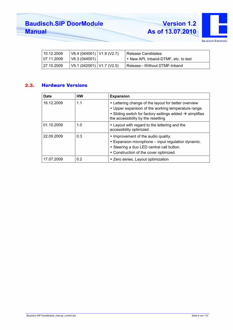
10.12.2009
07.11.2009
V6.4 (044001)
V6.3 (044001)
V1.9 (V2.7) Release Candidates
•• New API, Inband-DTMF, etc. to test
27.10.2009 V5.1 (042001) V1.7 (V2.5) Release - Without DTMF-Inband
2.3. Hardware Versions
Date HW Expansion
16.12.2009 1.1 •• Lettering change of the layout for better overview
•• Upper expansion of the working temperature range.
•• Sliding switch for factory settings added à simplifies
the accessibility by the resetting
01.10.2009 1.0 •• Layout with regard to the lettering and the
accessibility optimized.
22.09.2009 0.3 •• Improvement of the audio quality.
•• Expansion microphone – input regulation dynamic.
•• Steering a duo LED central call button.
•• Construction of the cover optimized.
17.07.2009 0.2 •• Zero series, Layout optimization
Baudisch.SIP DoorModule_manual_current.doc Seite 7 von 112
Baudisch.SIP DoorModule
Manual
Version 1.2
As of 13.07.2010
2.4. Foundation of VoiP and SIP
The transmission of voice and images over the Ethernet and by IP is increasingly replacing
analog and ISDN-based transmission technologies.
The voice communication and image are converted into digital signals (VoIP=VoiceOverIP) and
are then transmitted over the IP network in a specific protocol such as SIP (Session Initiation
Protocol). Also, by using an IP camera, the digital video image data is sent over the same
network.
2.4.1. SIP and H.323
Apart from SIP, systems are also using the H.323 protocol. This method can simplistically also
be called ISDN over IP. However, it requires very powerful hardware and has several
disadvantages related to firewalls and network integration.
The Baudisch.SIP door module ECO/MAXI solely supports the sustainable SIP protocol.
2.4.2. Advantages of the SIP protocol
This creates substantial advantages, especially in companies which already have IT networks
and structured cabelling. Existing IT resources can be used; there is no need for an additional
cable network.
Where there is no cable connection, intercoms can be operated over W-LAN (IP radio link).
This ideal intercom system provides a solution even in private homes where almost always LAN
connections are found.
Other devices such as specific exchange or switchboard technology, storey distributors or
interface modules are also unnecessary.
2.4.2.1 Transmission and connection types of calls
Direct connections (Door intercom – PoE switch – IP phone)
For the simplest applications, for example in a home. The intercoms call the IP address of an IP
phone directly. By connecting several ring buttons, every ring button can have a different call
destination assigned.
Public SIP provider
Door intercom and IP phone are switched, free of charge, via a public SIP provider (internet
access and at least one DSL connection required). Transfers from SIP to the fixed and mobile
phone network are offered on favourable terms. This makes the door intercom a worldwide
telephone. Even switching functions, e.g. the door opening, can be carried out while on the
road.
Local SIP server software
This software can be run on any PC. For example, the 3CX-SIP-server software (also available
as freeware) runs directly on a Windows server. Alternatively, Asterisk is frequently installed on
a Linux PC.
IP phone systems
Many phone system manufacturer offer devices with SIP features. Our door intercoms can also
be directly connected there.
A current compatibility list is available on request.
Baudisch.SIP DoorModule_manual_current.doc Seite 8 von 112
Baudisch.SIP DoorModule
Manual
Version 1.2
As of 13.07.2010
3. Product Description
3.1. General Information
The Baudisch.SIP door module is a door intercom with internal loudspeaker, hands-free
microphone, inputs for external call buttons as well as relay outputs for door opening and light.
The device is the ideal solution for vandalism protection requirements or for outdoor
applications. It includes a phone directory with 76 speed dialling numbers, which can be
triggered via external buttons. Fast dialling and very good quality giving a clear and loud replay
are the characteristic features of this robust intercom.
The features are:
• Suitable for outdoor applications (protection class IP65 toward the front), poke-through
protection by using the Baudisch V4A front panel or another front with a similar hole profile.
• Rear mount module, for example for mail box systems, cabinets or other panels. Suitable
mounting frames are available.
• The voice connection occurs per VoiceOverIP (VoIP) over the installed Ethernet-LAN either
directly to a SIP capable phone, via a SIP phone system or per internet over a SIP provider.
• Priority of voice from the control station; which means dialog is possible even if there are
loud noises in the intercom’s environment.
• The calls are triggered through the external ring buttons, which can be directly connected to
the module. The maximum number of call buttons is dependent of the chosen model and
optional expansions. The connection of a minumum of 4 call buttons and a central call
button is possible by all models in the basic setup.
• Simple configuration via the built-in web server which is pre-installed in a required language
version (German, English, French, Italian).
• Switch output for the door opening per DTMF dial or per UDP command.
• Emergency call logic: Features such as redialling, call forwarding to alternative destinations
and call acceptance confirmation of the control station over DTMF.
• The electrical supply occurs over the LAN (PoE). Alternatively, a power supply can be
connected.
• There is a cheaper ECO version available, where the connection possibilities are limited to
a maximum of 5 ring buttons and one relay for the door opening.
• The model MAXI has in comparison to the ECO version a second relay, a built-in Ethernet
LAN switch for the connection and supply of a Baudisch.CP-CAM (or a linkage of several
intercoms), a Baudisch.EasyLan-Bus for the connection of Baudisch switch components
and a cable ribbon connector for a keypad module or for matrix boards, allowing up to 76
ring buttons to be connected.
Baudisch.SIP DoorModule_manual_current.doc Seite 9 von 112
Baudisch.SIP DoorModule
Manual
Version 1.2
As of 13.07.2010
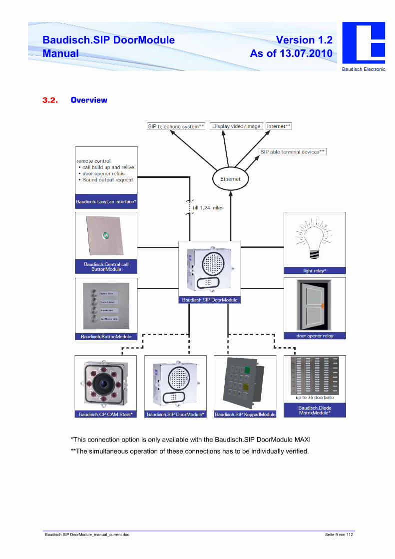
3.2. Overview
*This connection option is only available with the Baudisch.SIP DoorModule MAXI
**The simultaneous operation of these connections has to be individually verified.
Baudisch.SIP DoorModule_manual_current.doc Seite 10 von 112
Baudisch.SIP DoorModule
Manual
Version 1.2
As of 13.07.2010
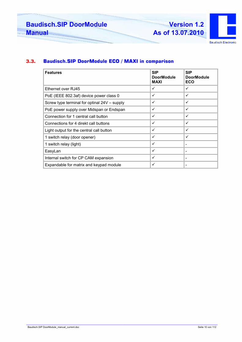
3.3. Baudisch.SIP DoorModule ECO / MAXI in comparison
Features SIP
DoorModule
MAXI
SIP
DoorModule
ECO
Ethernet over RJ45 ü ü
PoE (IEEE 802.3af) device power class 0 ü ü
Screw type terminal for optinal 24V – supply ü ü
PoE power supply over Midspan or Endspan ü ü
Connection for 1 central call button ü ü
Connections for 4 direkt call buttons ü ü
Light output for the central call button ü ü
1 switch relay (door opener) ü ü
1 switch relay (light) ü -
EasyLan ü -
Internal switch for CP CAM expansion ü -
Expandable for matrix and keypad module ü -
Baudisch.SIP DoorModule_manual_current.doc Seite 11 von 112
Baudisch.SIP DoorModule
Manual
Version 1.2
As of 13.07.2010
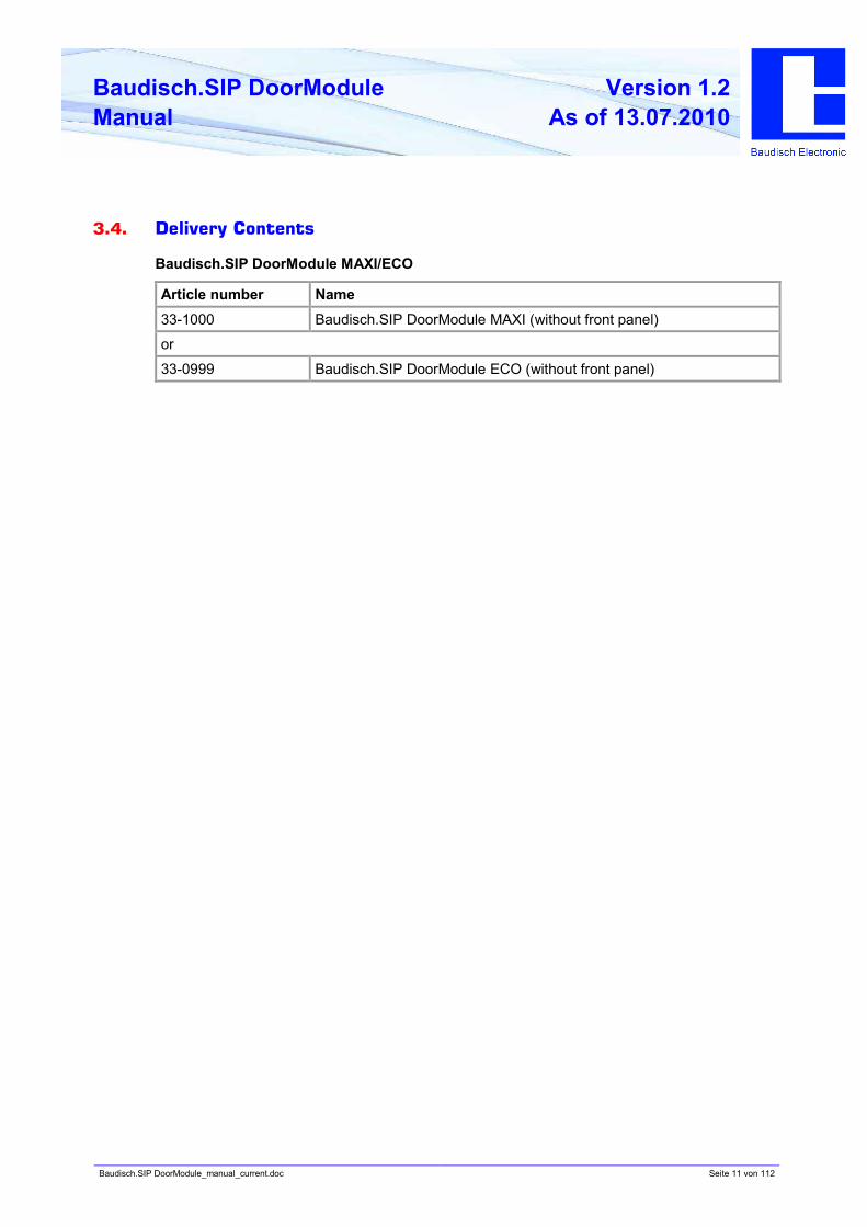
3.4. Delivery Contents
Baudisch.SIP DoorModule MAXI/ECO
Article number Name
33-1000 Baudisch.SIP DoorModule MAXI (without front panel)
or
33-0999 Baudisch.SIP DoorModule ECO (without front panel)
Baudisch.SIP DoorModule_manual_current.doc Seite 12 von 112
Baudisch.SIP DoorModule
Manual
Version 1.2
As of 13.07.2010
Optional Accessories
Article number Name
33-1119 V4A front panel for door module
33-1218 Dummy front panel for empty module spaces
33-1001 Baudisch.CP-CAM Steel (without front panel)
33-1121 V4A front panel for CP-CAM Steel
33-1116 Baudisch.ButtonModule 4 buttons (without front panel and buttons)
33-1122 V4A front panel for ButtonModule
33-1144 Baudisch central call Button.Module (incl. front panel)
33-1202 Baudisch.KeypadModule 16B (without front panel)
33-1198 V4A front panel for KeypadModule 16B
33-1200 SIP DisplayModule
33-1201 V4A front panel for SIP DisplayModule
33-1127 Baudisch Diode MatrixModule
33-1123 Baudisch system housing IP65
27-0235A Baudisch Mounting frame single RB 120x120x5,7mm (Rear Bolting)
27-0235B Baudisch Mounting frame douple RB 230x120x5,7mm
-2-fach 230x120x5,7mm à Art.-No.27-0235B
-3-fach 340x120x5,7mm à Art.-Nr.27-0235C
-4-fach 450x120x5,7mm à Art.-Nr.27-0235D
27-0235C Baudisch Mounting frame triple RB 340x120x5,7mm
-2-fach 230x120x5,7mm à Art.-Nr.27-0235B
-3-fach 340x120x5,7mm à Art.-Nr.27-0235C
-4-fach 450x120x5,7mm à Art.-Nr.27-0235D
27-0235D Baudisch Mounting frame quadruple RB 450x120x5,7mm
27-0281A Baudisch Mounting frame single FB 150x150x7,5mm (Front Bolting)
27-0281B Baudisch Mounting frame douple FB 260x150x7,5mm
27-0281C Baudisch Mounting frame triple FB 370x150x7,5mm
27-0281D Baudisch Mounting frame quadruple FB 480x150x7,5mm
33-1193 Screw set V2A M5x12mm with 2 hole inward urge
33-1194 Screw set 4,8x50mm with 2 hole inward urge and cavity dowels
33-1195 Screw set 4,8x50mm with torx drive and cavity dowels
33-1196 Screw set M5x16mm with torx drive and safety pin
27-0169 Special bit tool for 2 hole inward urge screws
27-0282A Flush-mounting box single 138x138x41mm
27-0282B Flush-mounting box double 248x138x41mm
27-0282C Flush-mounting box triple 358x138x41mm
27-0282D Flush-mounting box quadruple 468x138x41mm
The optional accessories are not included in the delivery contents and must be ordered
separately.
Baudisch.SIP DoorModule_manual_current.doc Seite 13 von 112
Baudisch.SIP DoorModule
Manual
Version 1.2
As of 13.07.2010
3.5. Optional Accessories
Name and Article Number Description
Product Image Product Information
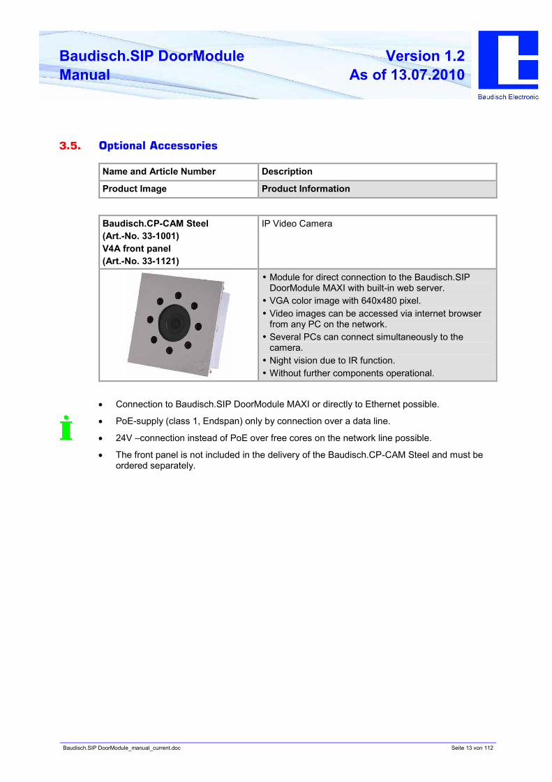
Baudisch.CP-CAM Steel
(Art.-No. 33-1001)
V4A front panel
(Art.-No. 33-1121)
IP Video Camera
•• Module for direct connection to the Baudisch.SIP
DoorModule MAXI with built-in web server.
•• VGA color image with 640x480 pixel.
•• Video images can be accessed via internet browser
from any PC on the network.
•• Several PCs can connect simultaneously to the
camera.
•• Night vision due to IR function.
•• Without further components operational.
• Connection to Baudisch.SIP DoorModule MAXI or directly to Ethernet possible.
• PoE-supply (class 1, Endspan) only by connection over a data line.
• 24V –connection instead of PoE over free cores on the network line possible.
• The front panel is not included in the delivery of the Baudisch.CP-CAM Steel and must be
ordered separately.
Baudisch.SIP DoorModule_manual_current.doc Seite 14 von 112
Baudisch.SIP DoorModule
Manual
Version 1.2
As of 13.07.2010
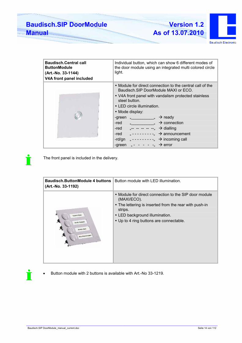
Baudisch.Central call
ButtonModule
(Art.-No. 33-1144)
V4A front panel included
Individual button, which can show 6 different modes of
the door module using an integrated multi colored circle
light.
•• Module for direct connection to the central call of the
Baudisch.SIP DoorModule MAXI or ECO.
•• V4A front panel with vandalism protected stainless
steel button.
•• LED circle illumination.
•• Mode display:
-green „__________„ à ready
-red „__________„ à connection
-red „-- -- -- -- --„ à dialling
-red „ - - - - - - - - -„ à announcement
-rd/gn „ - - - - - - - - -„ à incoming call
-green „ - - - - -„ à error
The front panel is included in the delivery.
Baudisch.ButtonModule 4 buttons
(Art.-No. 33-1192)
Button module with LED illumination.
•• Module for direct connection to the SIP door module
(MAXI/ECO).
•• The lettering is inserted from the rear with push-in
strips.
•• LED background illumination.
•• Up to 4 ring buttons are connectable.
• Button module with 2 buttons is available with Art.-No 33-1219.
Baudisch.SIP DoorModule_manual_current.doc Seite 15 von 112
Baudisch.SIP DoorModule
Manual
Version 1.2
As of 13.07.2010
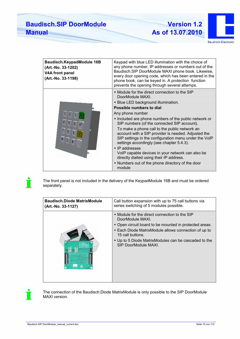
Baudisch.KeypadModule 16B
(Art.-No. 33-1202)
V4A front panel
(Art.-No. 33-1198)
Keypad with blue LED illumination with the choice of
any phone number, IP addresses or numbers out of the
Baudisch.SIP DoorModule MAXI phone book. Likewise,
every door opening code, which has been entered in the
phone book, can be keyed in. A protection function
prevents the opening through several attemps.
•• Module for the direct connection to the SIP
DoorModule MAXI.
•• Blue LED background illumination.
Possible numbers to dial
Any phone number
•• Included are phone numbers of the public network or
SIP numbers (of the connected SIP account).
To make a phone call to the public network an
account with a SIP provider is needed. Adjusted the
SIP settings in the configuration menu under the VoIP
settings accordingly (see chapter 5.4.3).
•• IP addresses
VoIP capable devices in your network can also be
directly dialled using their IP address.
•• Numbers out of the phone directory of the door
module
The front panel is not included in the delivery of the KeypadModule 16B and must be ordered
separately.
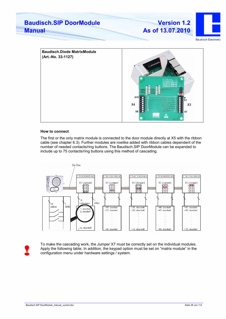
Baudisch.Diode MatrixModule
(Art.-No. 33-1127)
Call button expansion with up to 75 call buttons via
series switching of 5 modules possible.
•• Module for the direct connection to the SIP
DoorModule MAXI.
•• Open circuit board to be mounted in protected areas.
•• Each Diode MatrixModule allows connection of up to
15 call buttons.
•• Up to 5 Diode MatrixModules can be cascaded to the
SIP DoorModule MAXI.
The connection of the Baudisch.Diode MatrixModule is only possible to the SIP DoorModule
MAXI version.
Baudisch.SIP DoorModule_manual_current.doc Seite 16 von 112
Baudisch.SIP DoorModule
Manual
Version 1.2
As of 13.07.2010
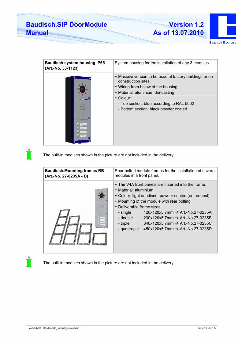
Baudisch system housing IP65
(Art.-No. 33-1123)
System housing for the installation of any 3 modules.
•• Massive version to be used at factory buildings or on
construction sites.
•• Wiring from below of the housing.
•• Material: aluminium die-casting
•• Colour:
- Top section: blue according to RAL 5002
- Bottom section: black powder coated
The built-in modules shown in the picture are not included in the delivery.
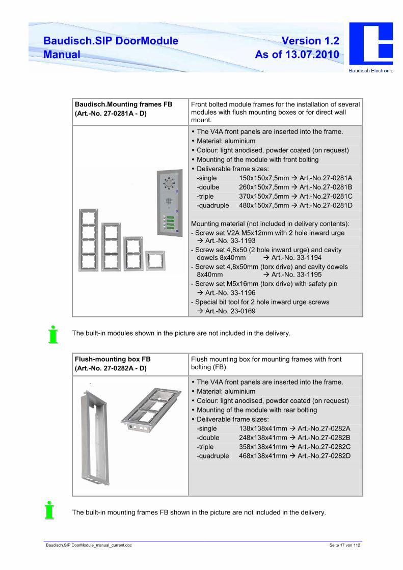
Baudisch.Mounting frames RB
(Art.-No. 27-0235A - D)
Rear bolted module frames for the installation of several
modules in a front panel.
•• The V4A front panels are inserted into the frame.
•• Material: aluminium
•• Colour: light anodised, powder coated (on request)
•• Mounting of the module with rear bolting
•• Deliverable frame sizes:
- single 120x120x5,7mm à Art.-No.27-0235A
- double 230x120x5,7mm à Art.-No.27-0235B
- triple 340x120x5,7mm à Art.-No.27-0235C
- quadruple 450x120x5,7mm à Art.-No.27-0235D
The built-in modules shown in the picture are not included in the delivery.
Baudisch.SIP DoorModule_manual_current.doc Seite 17 von 112
Baudisch.SIP DoorModule
Manual
Version 1.2
As of 13.07.2010
Baudisch.Mounting frames FB
(Art.-No. 27-0281A - D)
Front bolted module frames for the installation of several
modules with flush mounting boxes or for direct wall
mount.
•• The V4A front panels are inserted into the frame.
•• Material: aluminium
•• Colour: light anodised, powder coated (on request)
•• Mounting of the module with front bolting
•• Deliverable frame sizes:
-single 150x150x7,5mm à Art.-No.27-0281A
-doulbe 260x150x7,5mm à Art.-No.27-0281B
-triple 370x150x7,5mm à Art.-No.27-0281C
-quadruple 480x150x7,5mm à Art.-No.27-0281D
Mounting material (not included in delivery contents):
- Screw set V2A M5x12mm with 2 hole inward urge
à Art.-No. 33-1193
- Screw set 4,8x50 (2 hole inward urge) and cavity
dowels 8x40mm à Art.-No. 33-1194
- Screw set 4,8x50mm (torx drive) and cavity dowels
8x40mm à Art.-No. 33-1195
- Screw set M5x16mm (torx drive) with safety pin
à Art.-No. 33-1196
- Special bit tool for 2 hole inward urge screws
à Art.-No. 23-0169
The built-in modules shown in the picture are not included in the delivery.
Flush-mounting box FB
(Art.-No. 27-0282A - D)
Flush mounting box for mounting frames with front
bolting (FB)
•• The V4A front panels are inserted into the frame.
•• Material: aluminium
•• Colour: light anodised, powder coated (on request)
•• Mounting of the module with rear bolting
•• Deliverable frame sizes:
-single 138x138x41mm à Art.-No.27-0282A
-double 248x138x41mm à Art.-No.27-0282B
-triple 358x138x41mm à Art.-No.27-0282C
-quadruple 468x138x41mm à Art.-No.27-0282D
The built-in mounting frames FB shown in the picture are not included in the delivery.
Baudisch.SIP DoorModule_manual_current.doc Seite 18 von 112
Baudisch.SIP DoorModule
Manual
Version 1.2
As of 13.07.2010
4. Starting up
4.1. Preconfiguration
After the installation, to activate the door module, an IP address in the address range of the
network has to be assigned to it. This setup can be carried out with a PC/laptop which is directly
connected to the door module along with an external 24V power supply (see chapter 4.2
Connection). Another possibility without external power would be to connect the door module to
a PC/laptop via a PoE switch.
To be able to connect to the door module, it is necessary that the PC/laptop temporarily is setup
for the IP address range of the door module. The address range is defined from 192.168.1.1 to
192.168.1.254 with the delivery. The door module has the address 192.168.1.200.
To configurate the door module, follow the coming instructions.
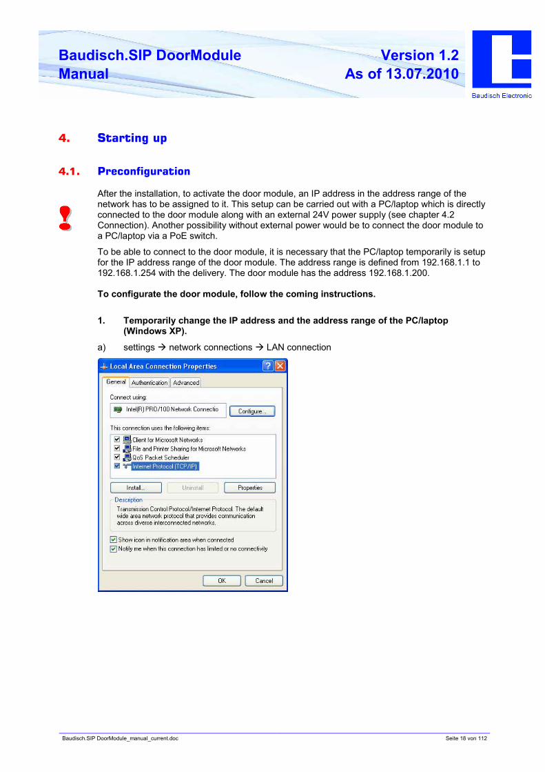
1. Temporarily change the IP address and the address range of the PC/laptop
(Windows XP).
a) settings à network connections à LAN connection
Baudisch.SIP DoorModule_manual_current.doc Seite 19 von 112
Baudisch.SIP DoorModule
Manual
Version 1.2
As of 13.07.2010
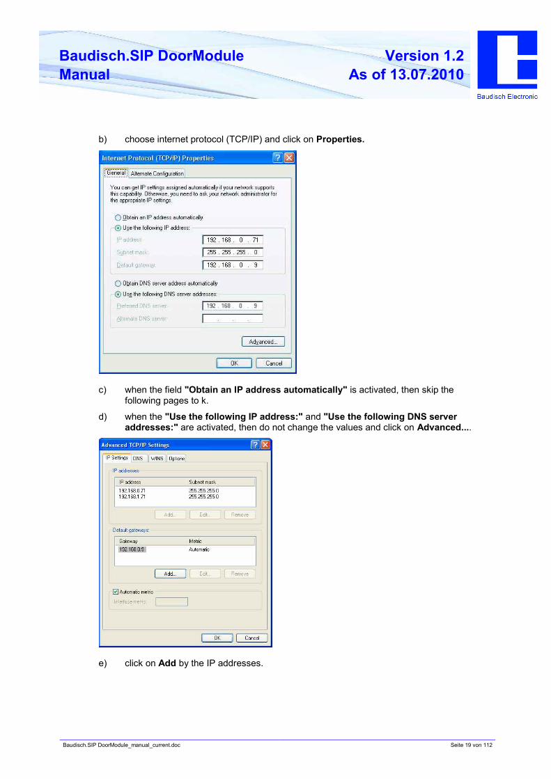
b) choose internet protocol (TCP/IP) and click on Properties.
c) when the field "Obtain an IP address automatically" is activated, then skip the
following pages to k.
d) when the "Use the following IP address:" and "Use the following DNS server
addresses:" are activated, then do not change the values and click on Advanced....
e) click on Add by the IP addresses.
Baudisch.SIP DoorModule_manual_current.doc Seite 20 von 112
Baudisch.SIP DoorModule
Manual
Version 1.2
As of 13.07.2010
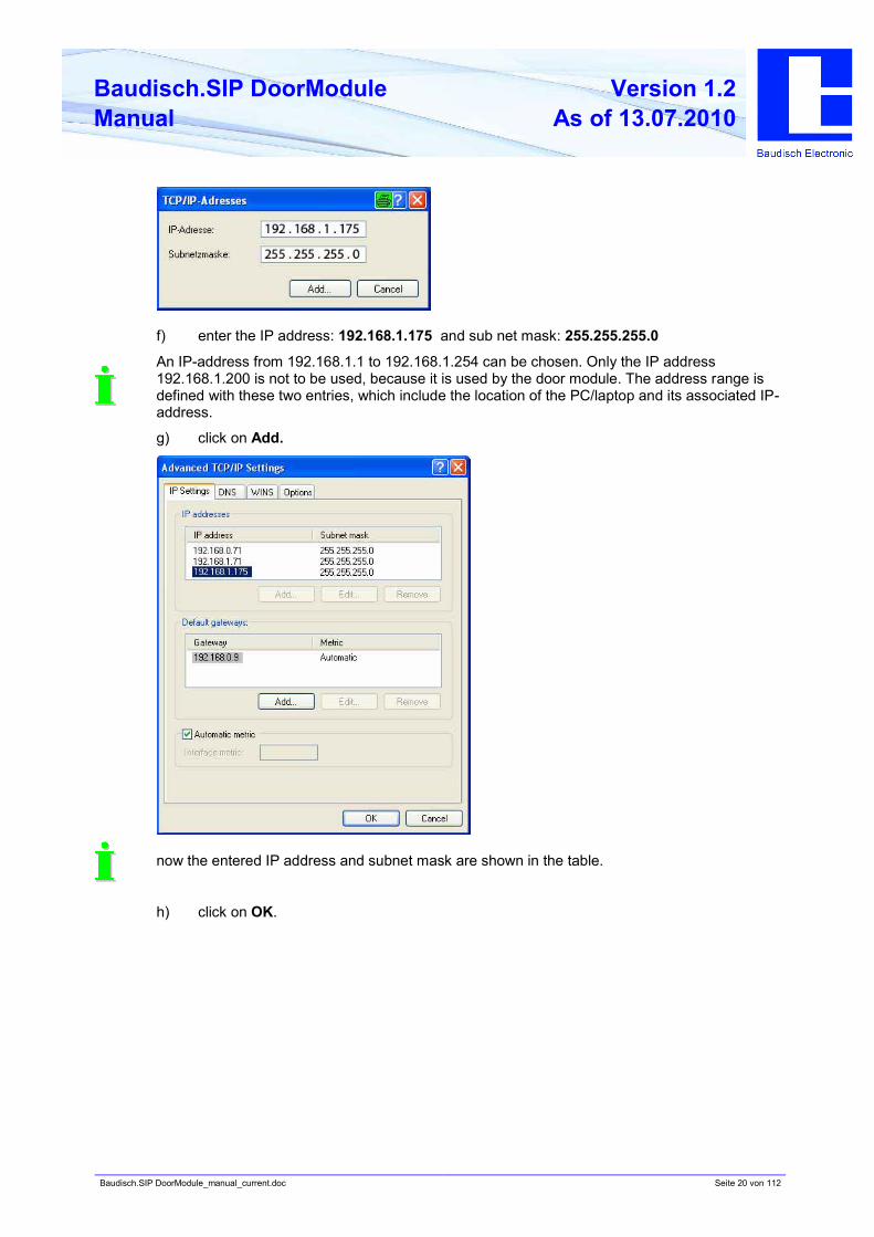
f) enter the IP address: 192.168.1.175 and sub net mask: 255.255.255.0
An IP-address from 192.168.1.1 to 192.168.1.254 can be chosen. Only the IP address
192.168.1.200 is not to be used, because it is used by the door module. The address range is
defined with these two entries, which include the location of the PC/laptop and its associated IP-
address.
g) click on Add.
now the entered IP address and subnet mask are shown in the table.
h) click on OK.
Baudisch.SIP DoorModule_manual_current.doc Seite 21 von 112
Baudisch.SIP DoorModule
Manual
Version 1.2
As of 13.07.2010
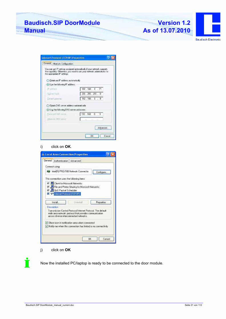
i) click on OK.
j) click on OK
Now the installed PC/laptop is ready to be connected to the door module.
Baudisch.SIP DoorModule_manual_current.doc Seite 22 von 112
Baudisch.SIP DoorModule
Manual
Version 1.2
As of 13.07.2010
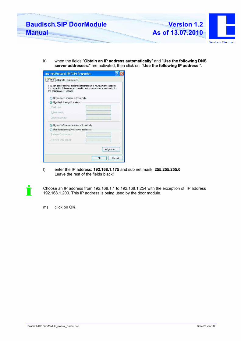
k) when the fields "Obtain an IP address automatically" and "Use the following DNS
server addresses:" are activated, then click on "Use the following IP address:".
l) enter the IP address: 192.168.1.175 and sub net mask: 255.255.255.0
Leave the rest of the fields black!
Choose an IP address from 192.168.1.1 to 192.168.1.254 with the exception of IP address
192.168.1.200. This IP address is being used by the door module.
m) click on OK.
Baudisch.SIP DoorModule_manual_current.doc Seite 23 von 112
Baudisch.SIP DoorModule
Manual
Version 1.2
As of 13.07.2010
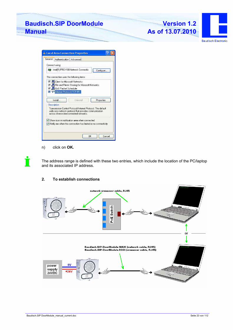
n) click on OK.
The address range is defined with these two entries, which include the location of the PC/laptop
and its associated IP address.
2. To establish connections
Baudisch.SIP DoorModule_manual_current.doc Seite 24 von 112
Baudisch.SIP DoorModule
Manual
Version 1.2
As of 13.07.2010
Establish connection from PC/laptop to door module via PoE switch.
or
• Connect the SIP door module directly to the PC/laptop with a network cable and to an
external power supply (+24VDC,1A secured). In this case, a crossover cable must be used
with the ECO version.
3. Start the configuration menu (see chapter 5.2)
• Access the starting page in the web browser using the factory preset IP address
"192.168.1.200".
• Choose „Settings VoIP“ and login using preset password "1234".
• Now you are in the sub menu network and you can carry out your network settings (see
chapter 5.4.1 Network).
Is the new IP address saved, then the configurations menu can only be accessed with this
address.
Baudisch.SIP DoorModule_manual_current.doc Seite 25 von 112
Baudisch.SIP DoorModule
Manual
Version 1.2
As of 13.07.2010
4.2. Connection
4.2.1. Baudisch.SIP door module connection
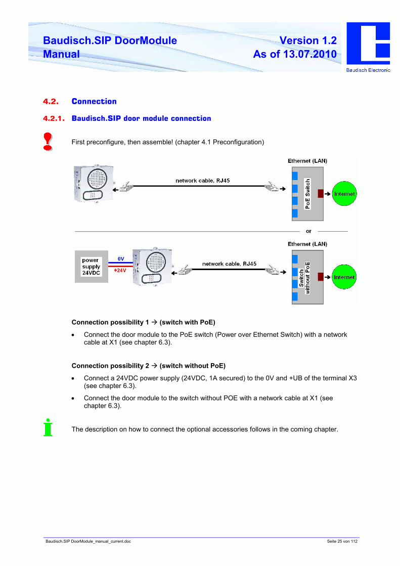
First preconfigure, then assemble! (chapter 4.1 Preconfiguration)
Connection possibility 1 à (switch with PoE)
• Connect the door module to the PoE switch (Power over Ethernet Switch) with a network
cable at X1 (see chapter 6.3).
Connection possibility 2 à (switch without PoE)
• Connect a 24VDC power supply (24VDC, 1A secured) to the 0V and +UB of the terminal X3
(see chapter 6.3).
• Connect the door module to the switch without POE with a network cable at X1 (see
chapter 6.3).
The description on how to connect the optional accessories follows in the coming chapter.
Baudisch.SIP DoorModule_manual_current.doc Seite 26 von 112
Baudisch.SIP DoorModule
Manual
Version 1.2
As of 13.07.2010
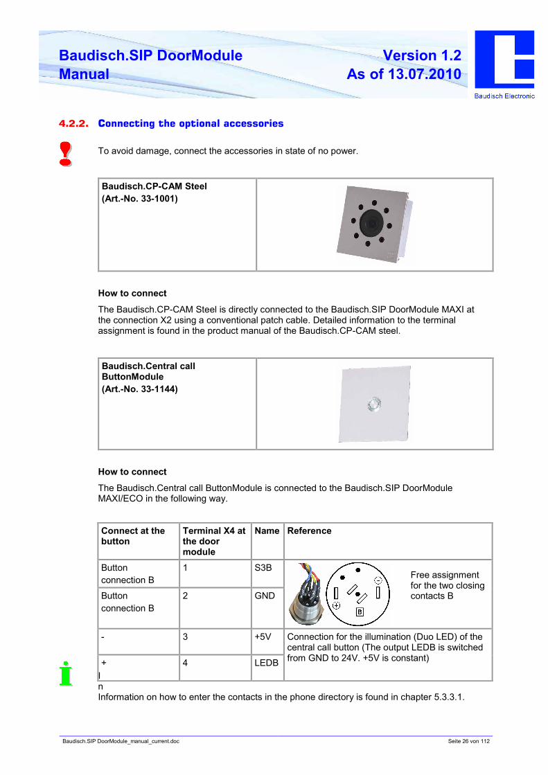
4.2.2. Connecting the optional accessories
To avoid damage, connect the accessories in state of no power.
Baudisch.CP-CAM Steel
(Art.-No. 33-1001)
How to connect
The Baudisch.CP-CAM Steel is directly connected to the Baudisch.SIP DoorModule MAXI at
the connection X2 using a conventional patch cable. Detailed information to the terminal
assignment is found in the product manual of the Baudisch.CP-CAM steel.
Baudisch.Central call
ButtonModule
(Art.-No. 33-1144)
How to connect
The Baudisch.Central call ButtonModule is connected to the Baudisch.SIP DoorModule
MAXI/ECO in the following way.
I
n
Information on how to enter the contacts in the phone directory is found in chapter 5.3.3.1.
Connect at the
button
Terminal X4 at
the door
module
Name Reference
Button
connection B
1 S3B
Button
connection B
2 GND
- 3 +5V
+ 4 LEDB
Connection for the illumination (Duo LED) of the
central call button (The output LEDB is switched
from GND to 24V. +5V is constant)
Free assignment
for the two closing
contacts B
Baudisch.SIP DoorModule_manual_current.doc Seite 27 von 112
Baudisch.SIP DoorModule
Manual
Version 1.2
As of 13.07.2010
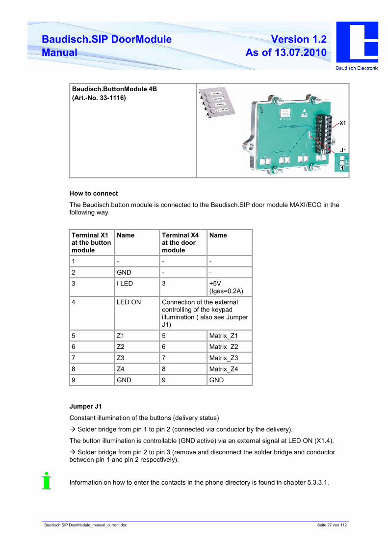
Baudisch.ButtonModule 4B
(Art.-No. 33-1116)
How to connect
The Baudisch.button module is connected to the Baudisch.SIP door module MAXI/ECO in the
following way.
Jumper J1
Constant illumination of the buttons (delivery status)
à Solder bridge from pin 1 to pin 2 (connected via conductor by the delivery).
The button illumination is controllable (GND active) via an external signal at LED ON (X1.4).
à Solder bridge from pin 2 to pin 3 (remove and disconnect the solder bridge and conductor
between pin 1 and pin 2 respectively).
Information on how to enter the contacts in the phone directory is found in chapter 5.3.3.1.
Terminal X1
at the button
module
Name Terminal X4
at the door
module
Name
1 - - -
2 GND - -
3 I LED 3 +5V
(Iges=0.2A)
4 LED ON Connection of the external
controlling of the keypad
illumination ( also see Jumper
J1)
5 Z1 5 Matrix_Z1
6 Z2 6 Matrix_Z2
7 Z3 7 Matrix_Z3
8 Z4 8 Matrix_Z4
9 GND 9 GND
Baudisch.SIP DoorModule_manual_current.doc Seite 28 von 112
Baudisch.SIP DoorModule
Manual
Version 1.2
As of 13.07.2010
Baudisch.Diode MatrixModule
(Art.-No. 33-1127)
How to connect
The first or the only matrix module is connected to the door module directly at X5 with the ribbon
cable (see chapter 6.3). Further modules are rowlike added with ribbon cables dependent of the
number of needed contacts/ring buttons. The Baudisch.SIP DoorModule can be expanded to
include up to 75 contacts/ring buttons using this method of cascading.
To make the cascading work, the Jumper X7 must be correctly set on the individual modules.
Apply the following table. In addition, the keypad option must be set on “matrix module” in the
configuration menu under hardware settings / system.
Baudisch.SIP DoorModule_manual_current.doc Seite 29 von 112
Baudisch.SIP DoorModule
Manual
Version 1.2
As of 13.07.2010
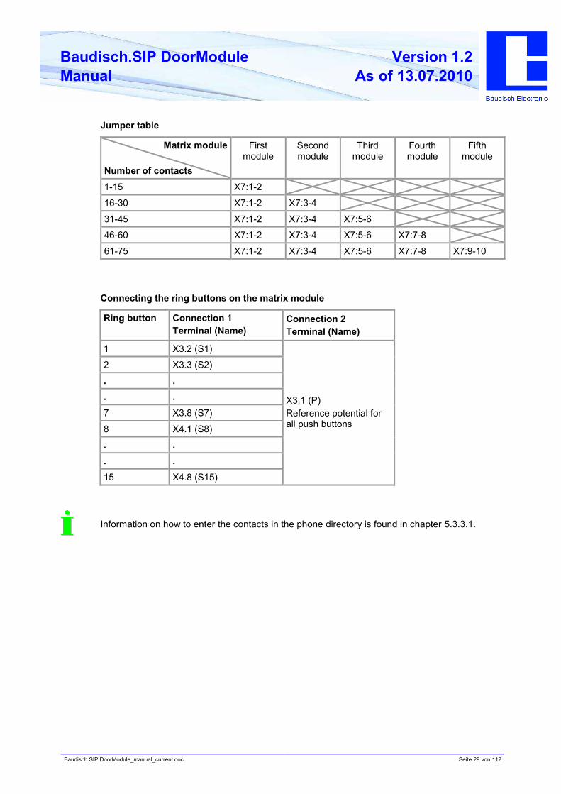
Jumper table
Matrix module
Number of contacts
First
module
Second
module
Third
module
Fourth
module
Fifth
module
1-15 X7:1-2
16-30 X7:1-2 X7:3-4
31-45 X7:1-2 X7:3-4 X7:5-6
46-60 X7:1-2 X7:3-4 X7:5-6 X7:7-8
61-75 X7:1-2 X7:3-4 X7:5-6 X7:7-8 X7:9-10
Connecting the ring buttons on the matrix module
Ring button Connection 1
Terminal (Name)
Connection 2
Terminal (Name)
1 X3.2 (S1)
2 X3.3 (S2)
. .
. .
7 X3.8 (S7)
8 X4.1 (S8)
. .
. .
15 X4.8 (S15)
X3.1 (P)
Reference potential for
all push buttons
Information on how to enter the contacts in the phone directory is found in chapter 5.3.3.1.
Baudisch.SIP DoorModule_manual_current.doc Seite 30 von 112
Baudisch.SIP DoorModule
Manual
Version 1.2
As of 13.07.2010
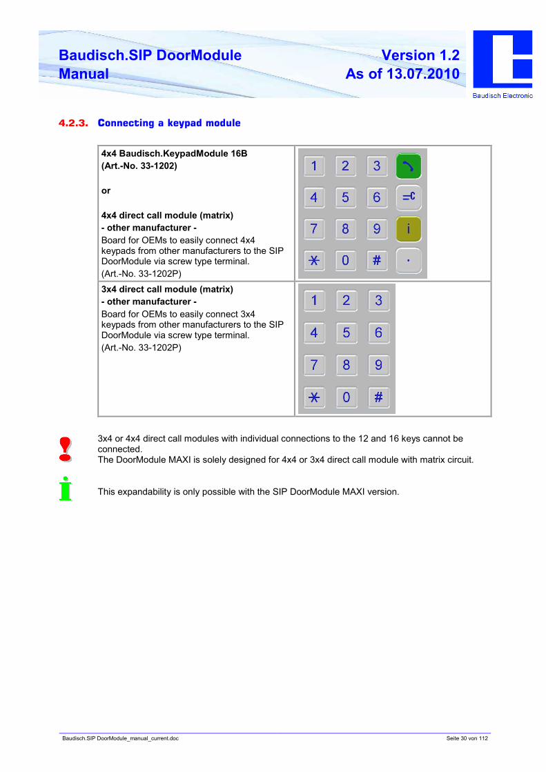
4.2.3. Connecting a keypad module
4x4 Baudisch.KeypadModule 16B
(Art.-No. 33-1202)
or
4x4 direct call module (matrix)
- other manufacturer -
Board for OEMs to easily connect 4x4
keypads from other manufacturers to the SIP
DoorModule via screw type terminal.
(Art.-No. 33-1202P)
3x4 direct call module (matrix)
- other manufacturer -
Board for OEMs to easily connect 3x4
keypads from other manufacturers to the SIP
DoorModule via screw type terminal.
(Art.-No. 33-1202P)
3x4 or 4x4 direct call modules with individual connections to the 12 and 16 keys cannot be
connected.
The DoorModule MAXI is solely designed for 4x4 or 3x4 direct call module with matrix circuit.
This expandability is only possible with the SIP DoorModule MAXI version.
Baudisch.SIP DoorModule_manual_current.doc Seite 31 von 112
Baudisch.SIP DoorModule
Manual
Version 1.2
As of 13.07.2010
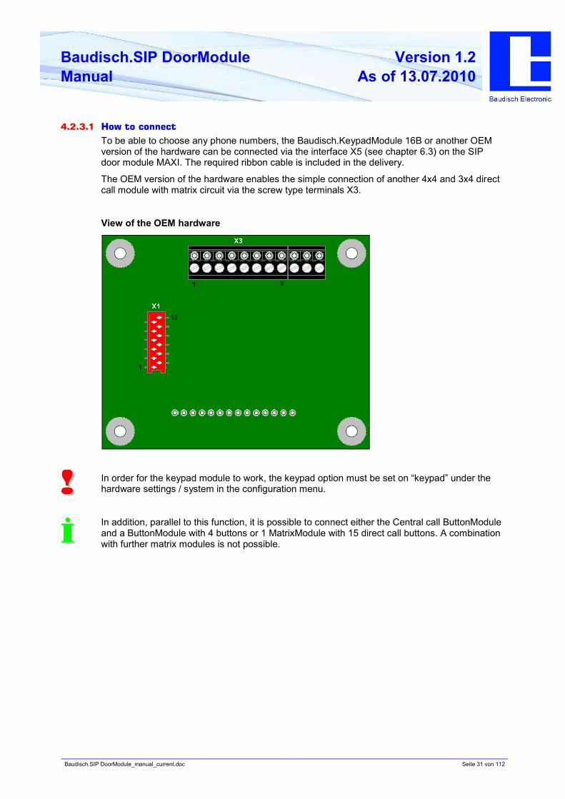
4.2.3.1 How to connect
To be able to choose any phone numbers, the Baudisch.KeypadModule 16B or another OEM
version of the hardware can be connected via the interface X5 (see chapter 6.3) on the SIP
door module MAXI. The required ribbon cable is included in the delivery.
The OEM version of the hardware enables the simple connection of another 4x4 and 3x4 direct
call module with matrix circuit via the screw type terminals X3.
View of the OEM hardware
In order for the keypad module to work, the keypad option must be set on “keypad” under the
hardware settings / system in the configuration menu.
In addition, parallel to this function, it is possible to connect either the Central call ButtonModule
and a ButtonModule with 4 buttons or 1 MatrixModule with 15 direct call buttons. A combination
with further matrix modules is not possible.
Baudisch.SIP DoorModule_manual_current.doc Seite 32 von 112
Baudisch.SIP DoorModule
Manual
Version 1.2
As of 13.07.2010
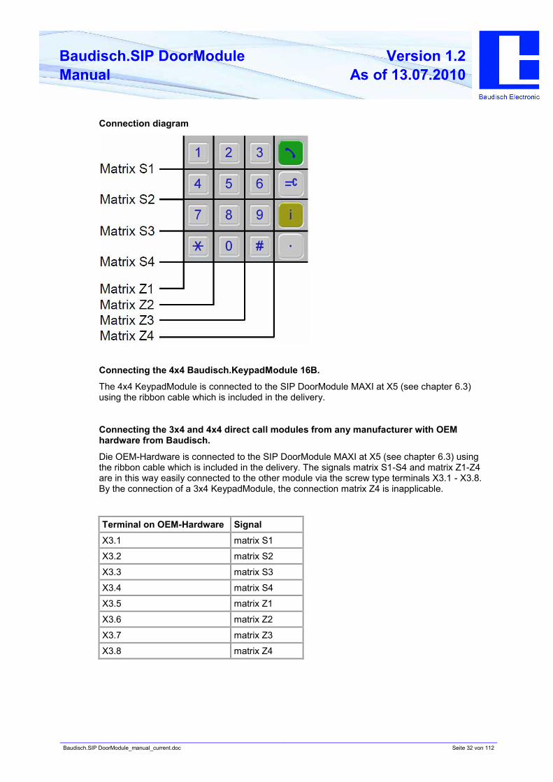
Connection diagram
Connecting the 4x4 Baudisch.KeypadModule 16B.
The 4x4 KeypadModule is connected to the SIP DoorModule MAXI at X5 (see chapter 6.3)
using the ribbon cable which is included in the delivery.
Connecting the 3x4 and 4x4 direct call modules from any manufacturer with OEM
hardware from Baudisch.
Die OEM-Hardware is connected to the SIP DoorModule MAXI at X5 (see chapter 6.3) using
the ribbon cable which is included in the delivery. The signals matrix S1-S4 and matrix Z1-Z4
are in this way easily connected to the other module via the screw type terminals X3.1 - X3.8.
By the connection of a 3x4 KeypadModule, the connection matrix Z4 is inapplicable.
Terminal on OEM-Hardware Signal
X3.1 matrix S1
X3.2 matrix S2
X3.3 matrix S3
X3.4 matrix S4
X3.5 matrix Z1
X3.6 matrix Z2
X3.7 matrix Z3
X3.8 matrix Z4
Baudisch.SIP DoorModule_manual_current.doc Seite 33 von 112
Baudisch.SIP DoorModule
Manual
Version 1.2
As of 13.07.2010
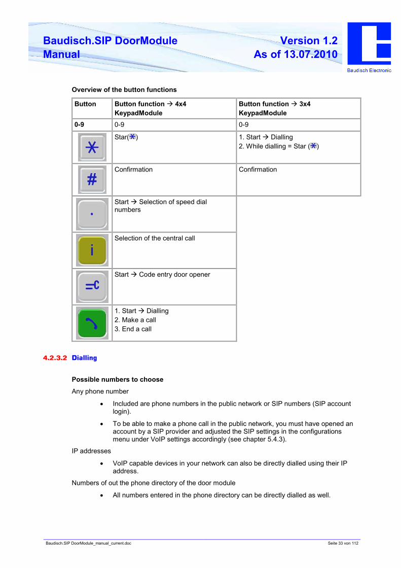
Overview of the button functions
Button Button function à 4x4
KeypadModule
Button function à 3x4
KeypadModule
0-9 0-9 0-9
Star( ) 1. Start à Dialling
2. While dialling = Star ( )
Confirmation Confirmation
Start à Selection of speed dial
numbers
Selection of the central call
Start à Code entry door opener
1. Start à Dialling
2. Make a call
3. End a call
4.2.3.2 Dialling
Possible numbers to choose
Any phone number
• Included are phone numbers in the public network or SIP numbers (SIP account
login).
• To be able to make a phone call in the public network, you must have opened an
account by a SIP provider and adjusted the SIP settings in the configurations
menu under VoIP settings accordingly (see chapter 5.4.3).
IP addresses
• VoIP capable devices in your network can also be directly dialled using their IP
address.
Numbers of out the phone directory of the door module
• All numbers entered in the phone directory can be directly dialled as well.
Baudisch.SIP DoorModule_manual_current.doc Seite 34 von 112
Baudisch.SIP DoorModule
Manual
Version 1.2
As of 13.07.2010
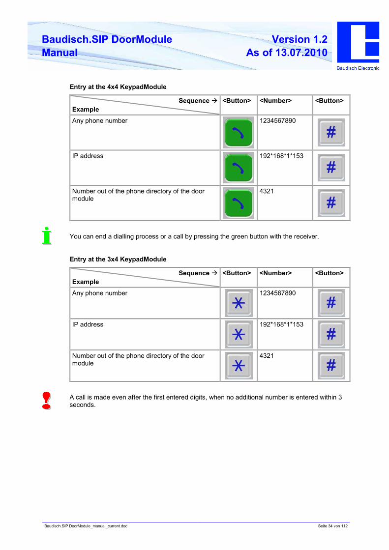
Entry at the 4x4 KeypadModule
Sequence à
Example
<Button> <Number> <Button>
Any phone number 1234567890
IP address 192*168*1*153
Number out of the phone directory of the door
module
4321
You can end a dialling process or a call by pressing the green button with the receiver.
Entry at the 3x4 KeypadModule
Sequence à
Example
<Button> <Number> <Button>
Any phone number 1234567890
IP address 192*168*1*153
Number out of the phone directory of the door
module
4321
A call is made even after the first entered digits, when no additional number is entered within 3
seconds.
Baudisch.SIP DoorModule_manual_current.doc Seite 35 von 112
Baudisch.SIP DoorModule
Manual
Version 1.2
As of 13.07.2010
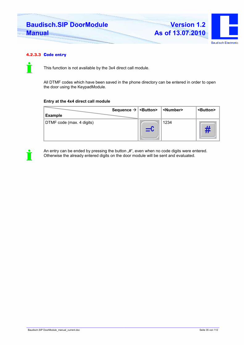
4.2.3.3 Code entry
This function is not available by the 3x4 direct call module.
All DTMF codes which have been saved in the phone directory can be entered in order to open
the door using the KeypadModule.
Entry at the 4x4 direct call module
Sequence à
Example
<Button> <Number> <Button>
DTMF code (max. 4 digits) 1234
An entry can be ended by pressing the button „#“, even when no code digits were entered.
Otherwise the already entered digits on the door module will be sent and evaluated.
Baudisch.SIP DoorModule_manual_current.doc Seite 36 von 112
Baudisch.SIP DoorModule
Manual
Version 1.2
As of 13.07.2010
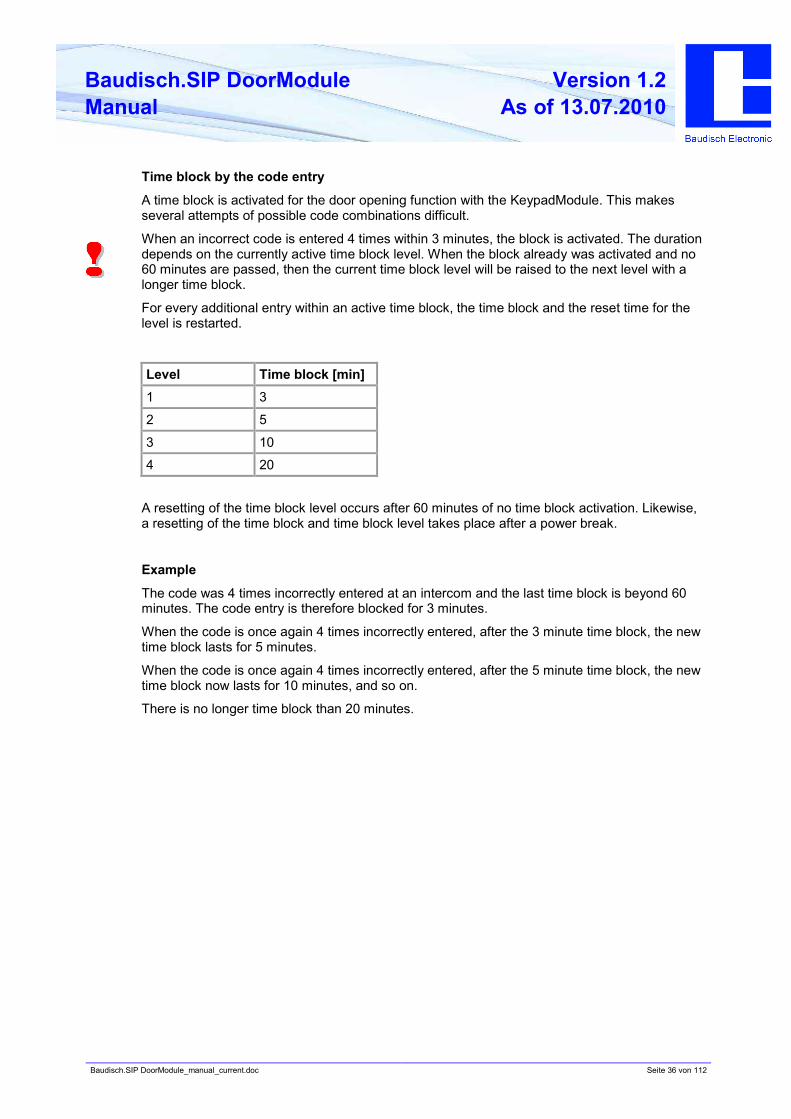
Time block by the code entry
A time block is activated for the door opening function with the KeypadModule. This makes
several attempts of possible code combinations difficult.
When an incorrect code is entered 4 times within 3 minutes, the block is activated. The duration
depends on the currently active time block level. When the block already was activated and no
60 minutes are passed, then the current time block level will be raised to the next level with a
longer time block.
For every additional entry within an active time block, the time block and the reset time for the
level is restarted.
Level Time block [min]
1 3
2 5
3 10
4 20
A resetting of the time block level occurs after 60 minutes of no time block activation. Likewise,
a resetting of the time block and time block level takes place after a power break.
Example
The code was 4 times incorrectly entered at an intercom and the last time block is beyond 60
minutes. The code entry is therefore blocked for 3 minutes.
When the code is once again 4 times incorrectly entered, after the 3 minute time block, the new
time block lasts for 5 minutes.
When the code is once again 4 times incorrectly entered, after the 5 minute time block, the new
time block now lasts for 10 minutes, and so on.
There is no longer time block than 20 minutes.
Baudisch.SIP DoorModule_manual_current.doc Seite 37 von 112
Baudisch.SIP DoorModule
Manual
Version 1.2
As of 13.07.2010
4.2.3.4 Central call
This function is not available with the 3x4 direct call module.
By pressing the yellow i-button at the 4x4 direct call module, the central call is dialled which has
been set up in the phone directory. To end a call press the green receiver button.
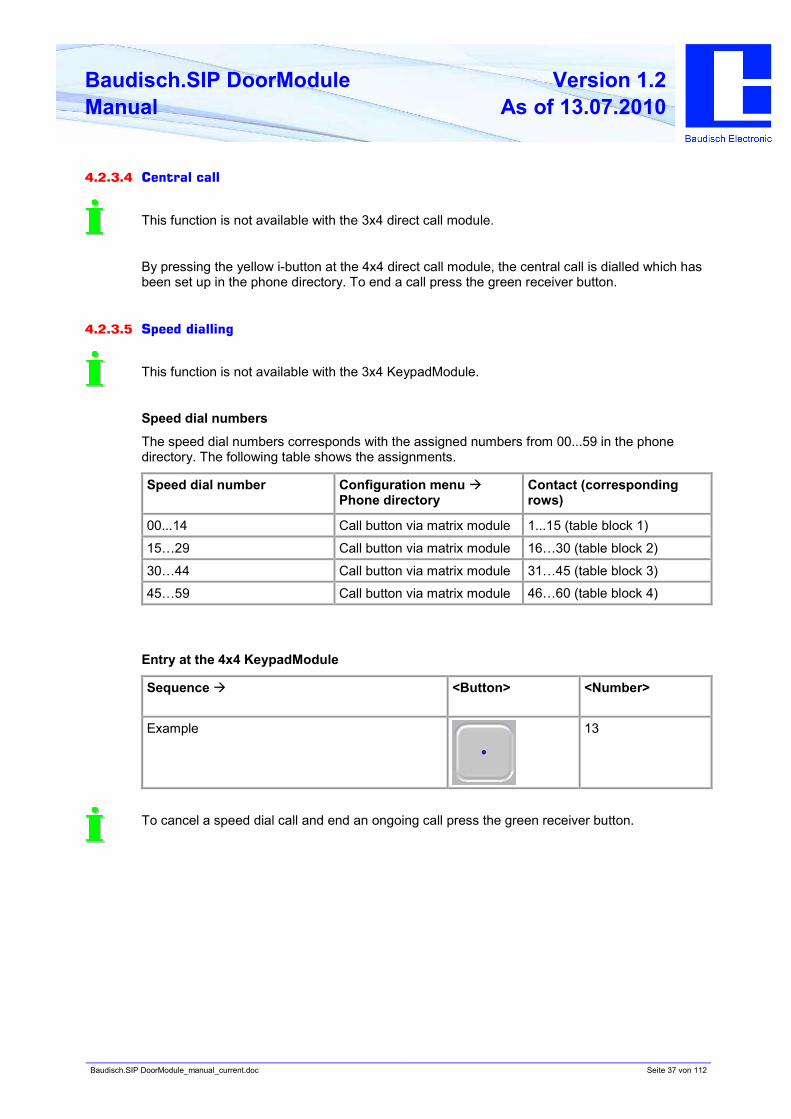
4.2.3.5 Speed dialling
This function is not available with the 3x4 KeypadModule.
Speed dial numbers
The speed dial numbers corresponds with the assigned numbers from 00...59 in the phone
directory. The following table shows the assignments.
Speed dial number Configuration menu à
Phone directory
Contact (corresponding
rows)
00...14 Call button via matrix module 1...15 (table block 1)
15…29 Call button via matrix module 16…30 (table block 2)
30…44 Call button via matrix module 31…45 (table block 3)
45…59 Call button via matrix module 46…60 (table block 4)
Entry at the 4x4 KeypadModule
Sequence à <Button> <Number>
Example 13
To cancel a speed dial call and end an ongoing call press the green receiver button.
Baudisch.SIP DoorModule_manual_current.doc Seite 38 von 112
Baudisch.SIP DoorModule
Manual
Version 1.2
As of 13.07.2010
4.2.3.6 Configuration of the keypad parameters
First the configuration selection must be started in order to configure the keypad parameters.
Activation of the configuration selection
To activate this mode, the following button combination must be pressed:
• Press and hold the key „0“. Now press the green receiver button.
à In addition to the error tone, a button confirmation follows. Then release the buttons.
• Press „*“ and „1“ simultaneously.
à A confirmation follows as well. Then release the buttons.
• Press „#“ and „2“ simultaneously.
à A short continuous tone follows as confirmation.
• Now you are in the selection of the configuration options.
There is a time limit by all the steps. It switches to idle mode after 10 seconds of no further
entry.
Configuration of the keypad parameters
à Setting of timeout for number entry
• Press the key „*“ and „1“ simultaneously in the configuration selection. A confirmation
follows.
• Two digits must be entered just like the speed dialling. Values in the range „01“ to „10“ (one
to ten seconds) can be entered. To large values are limited to 10 seconds and „00“ is
corrected to „01“.
• After the entry of the new timeout value a confirmation follows and the keypad switches to
idle mode. The procedure „activation of the configuration selection“ must be
reaccomplished if further settings are to be made.
Baudisch.SIP DoorModule_manual_current.doc Seite 39 von 112
Baudisch.SIP DoorModule
Manual
Version 1.2
As of 13.07.2010
4.2.3.7 Tone signals
Pressing the keys
• Confirmation tone (pressed key)
• No confirmation tone (pressed more than 2 keys or no key)
• Negative confirmation 1 – button has currently no function
• Negative confirmation 2 – keypad is blocked
Alarm
• Alarm tone sequence
• Confirmation from intercom by dialling (normal confirmation tone)
Error tone (general)
• Incorrect code entry
• Function could not be accomplished (for example call request when intercom is not in idle
mode).
Door opener
• Signal that block is removed.
4.2.3.8 Ending a call
A dialling process or a call can be ended by pressing the green receiver button, when no entry
mode is active. This corresponds to pressing the ring button at the door module. Ending a call is
always possible, even when the keypad is blocked. Likewise, repressing a ring button ends the
dialling process or the call.
Baudisch.SIP DoorModule_manual_current.doc Seite 40 von 112
Baudisch.SIP DoorModule
Manual
Version 1.2
As of 13.07.2010
5. Use and configuration
5.1. Starting requirements
• Connection of the SIP door module with an Ethernet 10/100 LAN.
• The supply of current can take place over the Ethernet via PoE (Power over Ethernet) or
with a suitable power supply.
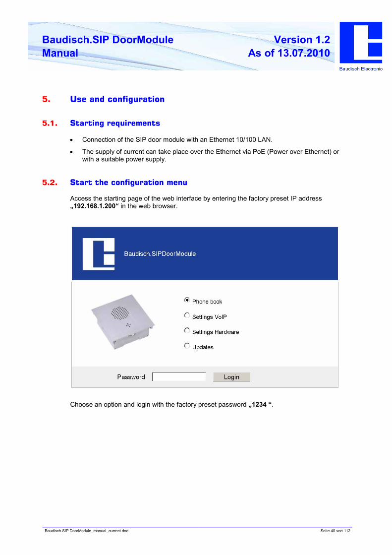
5.2. Start the configuration menu
Access the starting page of the web interface by entering the factory preset IP address
„192.168.1.200“ in the web browser.
Choose an option and login with the factory preset password „1234 “.
Baudisch.SIP DoorModule_manual_current.doc Seite 41 von 112
Baudisch.SIP DoorModule
Manual
Version 1.2
As of 13.07.2010
5.3. Phone directory
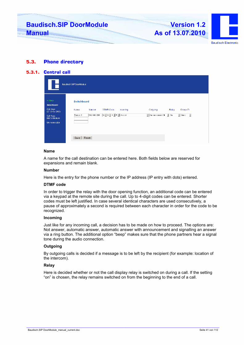
5.3.1. Central call
Name
A name for the call destination can be entered here. Both fields below are reserved for
expansions and remain blank.
Number
Here is the entry for the phone number or the IP address (IP entry with dots) entered.
DTMF code
In order to trigger the relay with the door opening function, an additional code can be entered
via a keypad at the remote site during the call. Up to 4-digit codes can be entered. Shorter
codes must be left justified. In case several identical characters are used consecutively, a
pause of approximately a second is required between each character in order for the code to be
recognized.
Incoming
Just like for any incoming call, a decision has to be made on how to proceed. The options are:
Not answer, automatic answer, automatic answer with announcement and signalling an answer
via a ring button. The additional option “beep” makes sure that the phone partners hear a signal
tone during the audio connection.
Outgoing
By outgoing calls is decided if a message is to be left by the recipient (for example: location of
the intercom).
Relay
Here is decided whether or not the call display relay is switched on during a call. If the setting
“on” is chosen, the relay remains switched on from the beginning to the end of a call.
Baudisch.SIP DoorModule_manual_current.doc Seite 42 von 112
Baudisch.SIP DoorModule
Manual
Version 1.2
As of 13.07.2010
Group ID
It is possible to assign a group of several call destinations with this setting. When a call
destination out of a group is called and not reached, then all call destinations out of this group
are called. They are called one by one according to how they are listed in the phone directory.
Other related settings are possible in chapter 5.5.3 under „global call parameters“ and „chain
call“.
Baudisch.SIP DoorModule_manual_current.doc Seite 43 von 112
Baudisch.SIP DoorModule
Manual
Version 1.2
As of 13.07.2010
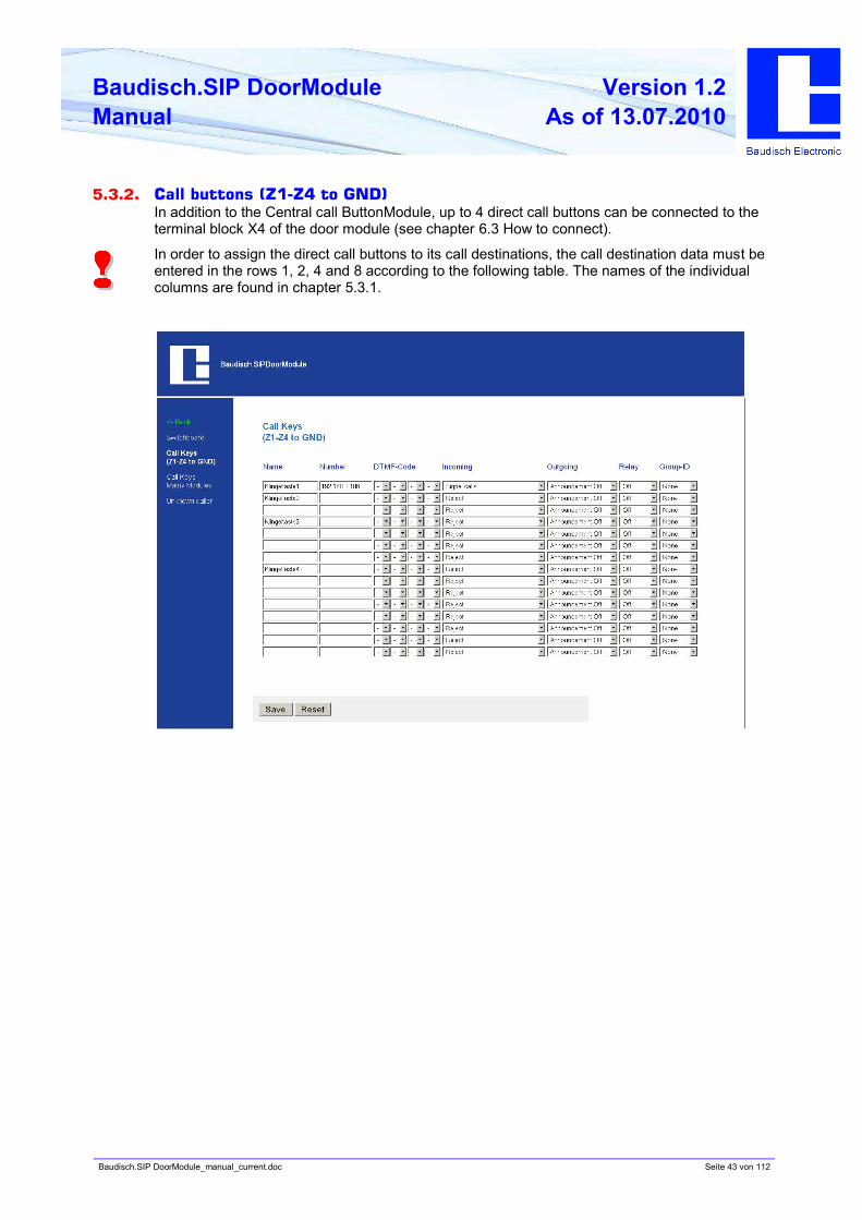
5.3.2. Call buttons (Z1-Z4 to GND)
In addition to the Central call ButtonModule, up to 4 direct call buttons can be connected to the
terminal block X4 of the door module (see chapter 6.3 How to connect).
In order to assign the direct call buttons to its call destinations, the call destination data must be
entered in the rows 1, 2, 4 and 8 according to the following table. The names of the individual
columns are found in chapter 5.3.1.
Baudisch.SIP DoorModule_manual_current.doc Seite 44 von 112
Baudisch.SIP DoorModule
Manual
Version 1.2
As of 13.07.2010
5.3.3. Call buttons via the matrix module
This expansion possibility is only available with the SIP DoorModule MAXI version.
The „MAXI“ version of the SIP door module has an expansion possibility of up to a total of 76
call buttons. This is possible with a series switch of a maximum of 5 Diode MatrixModules (see
chapter 3.5 Optional Accessories). Each module has 15 connections for ring buttons and one
connection for another diode matrix module. An expansion to 76 ring buttons is possible with
the central call button and the 5 x 15 connections of the individual modules.
When the fifth diode matrix module is connected, the 4 direct call buttons of the DoorModule
MAXI can no longer be used.
Information on how to connect the MatrixModule is found in chapter 4.2.2 and information about
the entries in the call destination list in the following chapter.
Baudisch.SIP DoorModule_manual_current.doc Seite 45 von 112
Baudisch.SIP DoorModule
Manual
Version 1.2
As of 13.07.2010
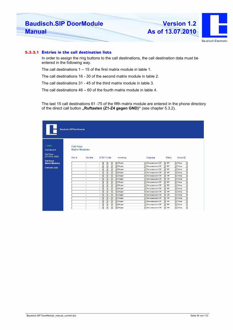
5.3.3.1 Entries in the call destination lists
In order to assign the ring buttons to the call destinations, the call destination data must be
entered in the following way.
The call destinations 1 – 15 of the first matrix module in table 1.
The call destinations 16 - 30 of the second matrix module in table 2.
The call destinations 31 - 45 of the third matrix module in table 3.
The call destinations 46 – 60 of the fourth matrix module in table 4.
The last 15 call destinations 61 -75 of the fifth matrix module are entered in the phone directory
of the direct call button „Ruftasten (Z1-Z4 gegen GND)“ (see chapter 5.3.2).
Baudisch.SIP DoorModule_manual_current.doc Seite 46 von 112
Baudisch.SIP DoorModule
Manual
Version 1.2
As of 13.07.2010
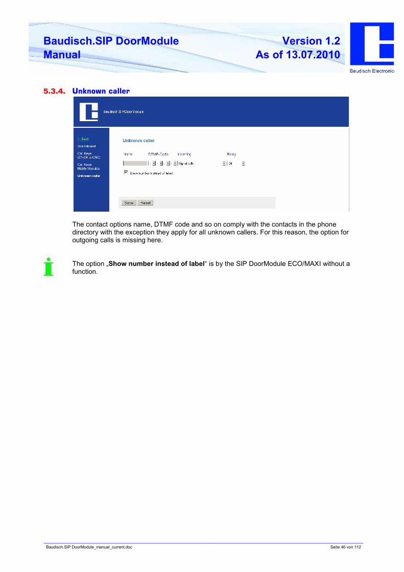
5.3.4. Unknown caller
The contact options name, DTMF code and so on comply with the contacts in the phone
directory with the exception they apply for all unknown callers. For this reason, the option for
outgoing calls is missing here.
The option „Show number instead of label“ is by the SIP DoorModule ECO/MAXI without a
function.
Baudisch.SIP DoorModule_manual_current.doc Seite 47 von 112
Baudisch.SIP DoorModule
Manual
Version 1.2
As of 13.07.2010
5.4. VoIP settings
Network
The corresponding settings for the network in which the SIP DoorModule is integrated, must be
entered here.
Language
Selection and setting possibilities about the used codecs.
SIP settings
The access data of the SIP provider must be entered here.
Additional SIP settings
Additional settings when required.
System
System settings such as passwords, time zone etc.
Baudisch.SIP DoorModule_manual_current.doc Seite 48 von 112
Baudisch.SIP DoorModule
Manual
Version 1.2
As of 13.07.2010
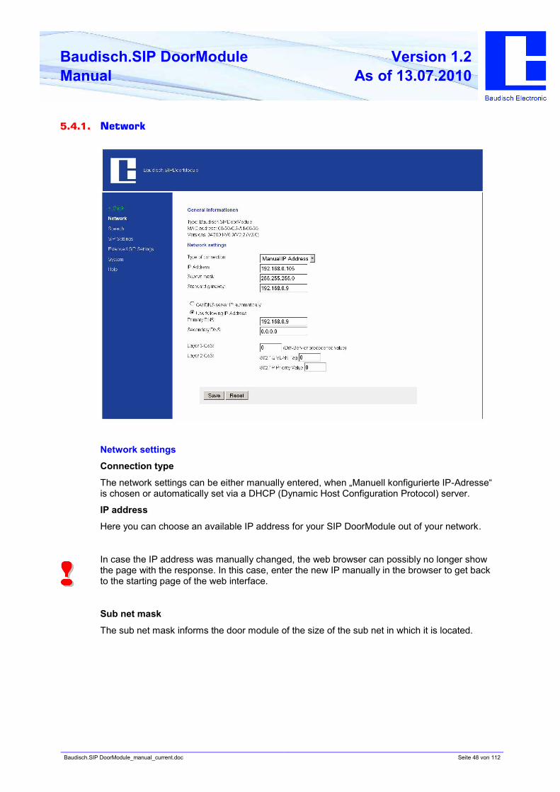
5.4.1. Network
Network settings
Connection type
The network settings can be either manually entered, when „Manuell konfigurierte IP-Adresse“
is chosen or automatically set via a DHCP (Dynamic Host Configuration Protocol) server.
IP address
Here you can choose an available IP address for your SIP DoorModule out of your network.
In case the IP address was manually changed, the web browser can possibly no longer show
the page with the response. In this case, enter the new IP manually in the browser to get back
to the starting page of the web interface.
Sub net mask
The sub net mask informs the door module of the size of the sub net in which it is located.
Baudisch.SIP DoorModule_manual_current.doc Seite 49 von 112
Baudisch.SIP DoorModule
Manual
Version 1.2
As of 13.07.2010
Standard Gateway
A gateway is a transmission point between different nets.
The settings for the DNS (Domain Name Server) can be set either manually or automatically via
the DHCP Server.
• Automatically obtain the DNS server IP
When this option is chosen, the fields for the primary and secondary DNS are shown gray and
the IP address is automatically obtained.
• Use the following address
If this option is chosen, the primary and secondary DNS must have been assigned addresses.
The settings for QoS (Quality of Service) are only to be adjusted by experienced system
administrators. Basically, these settings serve to prioritize the data packages for the voice
transmission compared to other network data communication.
Baudisch.SIP DoorModule_manual_current.doc Seite 50 von 112
Baudisch.SIP DoorModule
Manual
Version 1.2
As of 13.07.2010
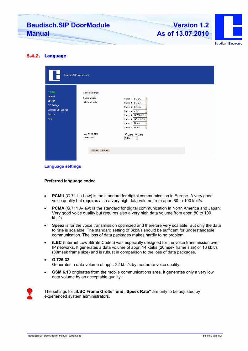
5.4.2. Language
Language settings
Preferred language codec
• PCMU (G.711 µ-Law) is the standard for digital commumication in Europe. A very good
voice quality but requires also a very high data volume from appr. 80 to 100 kbit/s.
• PCMA (G.711 A-law) is the standard for digital communication in North America and Japan.
Very good voice quality but requires also a very high data volume from appr. 80 to 100
kbit/s.
• Speex is for the voice transmission optimized and therefore very scalable. But only the data
to rate is scalable. The standard setting of 8kbit/s should be sufficent for understandable
communication. The loss of data packages makes hardly to no problem.
• iLBC (Internet Low Bitrate Codec) was especially designed for the voice transmission over
IP networks. It generates a data volume of appr. 14 kbit/s (20msek frame size) or 16 kbit/s
(30msek frame size) and is rubust in comparison to the loss of data packages.
• G.726-32
Generates a data volume of appr. 32 kbit/s by moderate voice quality.
• GSM 6.10 originates from the mobile communications area. It generates only a very low
data volume by an acceptable quality.
The settings for „iLBC Frame Größe“ und „Speex Rate“ are only to be adjusted by
experienced system administrators.
Baudisch.SIP DoorModule_manual_current.doc Seite 51 von 112
Baudisch.SIP DoorModule
Manual
Version 1.2
As of 13.07.2010
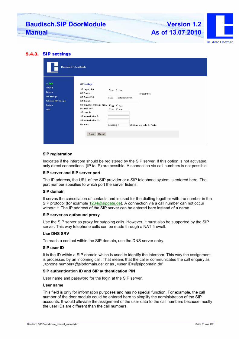
5.4.3. SIP settings
SIP registration
Indicates if the intercom should be registered by the SIP server. If this option is not activated,
only direct connections (IP to IP) are possible. A connection via call numbers is not possible.
SIP server and SIP server port
The IP address, the URL of the SIP provider or a SIP telephone system is entered here. The
port number specifies to which port the server listens.
SIP domain
It serves the cancellation of contacts and is used for the dialling together with the number in the
SIP protocol (for example [email protected]). A connection via a call number can not occur
without it. The IP address of the SIP server can be entered here instead of a name.
SIP server as outbound proxy
Use the SIP server as proxy for outgoing calls. However, it must also be supported by the SIP
server. This way telephone calls can be made through a NAT firewall.
Use DNS SRV
To reach a contact within the SIP domain, use the DNS server entry.
SIP user ID
It is the ID within a SIP domain which is used to identify the intercom. This way the assignment
is processed by an incoming call. That means that the caller communicates the call enquiry as
„<phone number>@sipdomain.de“ or as „<user ID>@sipdomain.de“.
SIP authentication ID and SIP authentication PIN
User name and password for the login at the SIP server.
User name
This field is only for information purposes and has no special function. For example, the call
number of the door module could be entered here to simplify the administration of the SIP
accounts. It would alleviate the assignment of the user data to the call numbers because mostly
the user IDs are different than the call numbers.
Baudisch.SIP DoorModule_manual_current.doc Seite 52 von 112
Baudisch.SIP DoorModule
Manual
Version 1.2
As of 13.07.2010
5.4.4. Additional SIP settings
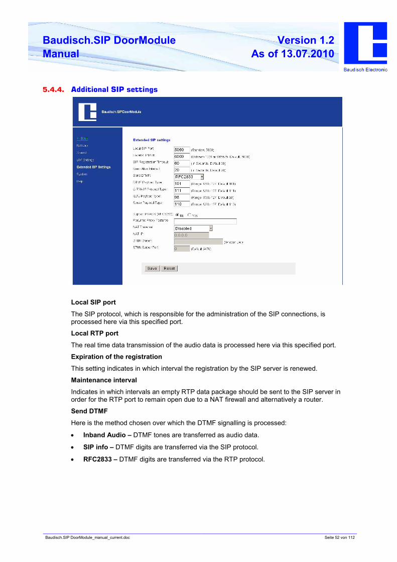
Local SIP port
The SIP protocol, which is responsible for the administration of the SIP connections, is
processed here via this specified port.
Local RTP port
The real time data transmission of the audio data is processed here via this specified port.
Expiration of the registration
This setting indicates in which interval the registration by the SIP server is renewed.
Maintenance interval
Indicates in which intervals an empty RTP data package should be sent to the SIP server in
order for the RTP port to remain open due to a NAT firewall and alternatively a router.
Send DTMF
Here is the method chosen over which the DTMF signalling is processed:
• Inband Audio – DTMF tones are transferred as audio data.
• SIP info – DTMF digits are transferred via the SIP protocol.
• RFC2833 – DTMF digits are transferred via the RTP protocol.
Baudisch.SIP DoorModule_manual_current.doc Seite 53 von 112
Baudisch.SIP DoorModule
Manual
Version 1.2
As of 13.07.2010
Data type to be used (DTMF, G.726-32, ILBC, Speex)
The data type to be used should be left on its standard setting. There is no special benefit for
the user here.
PRACK support (provisional acknowledge)
If this setting is activated, specific signalling in the SIP protocol is secured.
Required proxy characteristics
Characteristics which the proxy server must handle.
NAT Traversal
Here is defined how the door module identifies its public IP address when the door module is
located behind a NAT firewall or alternatively a router. This can be done either by a permanent
IP address (for example a dedicated line) with the option use NAT IP or by a dynamic
assignment via a STUN server. This option can be deactivated when exclusively a local network
is used.
NAT IP
Describes the IP address of the door module from the view of the internet (WAN address). This
should automatically occur via a STUN server by a dynamic assignment.
STUN server and STUN server port
IP or URL of the server, over which the current, public IP address of the door module should be
identified and its port number.
Baudisch.SIP DoorModule_manual_current.doc Seite 54 von 112
Baudisch.SIP DoorModule
Manual
Version 1.2
As of 13.07.2010
5.4.5. System
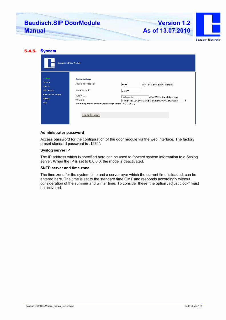
Administrator password
Access password for the configuration of the door module via the web interface. The factory
preset standard password is „1234“.
Syslog server IP
The IP address which is specified here can be used to forward system information to a Syslog
server. When the IP is set to 0.0.0.0, the mode is deactivated.
SNTP server and time zone
The time zone for the system time and a server over which the current time is loaded, can be
entered here. The time is set to the standard time GMT and responds accordingly without
consideration of the summer and winter time. To consider these, the option „adjust clock“ must
be activated.
Baudisch.SIP DoorModule_manual_current.doc Seite 55 von 112
Baudisch.SIP DoorModule
Manual
Version 1.2
As of 13.07.2010
5.5. Hardware settings
Audio
Settings for the precedence control of the speaker and microphone levels by the connection
with another intercom, as well as the switch barrier and switch duration.
Signalling settings for the volume of the ring tone and the signal tones.
System
Settings for the function and pulse duration of relay 1 and 2, the door opener signalling, the ID
announcement, the extensionport function and the keypad options.
Call options
Settings
...for the call duration, the dialling and the redial attempts.
...for the request for acknowledgement via DTMF characters.
...for the call buttons of the matrix module, the central call button as well as the direct call button
(Z1-4 to GND).
...for the number of cycles of the chain calls.
Status / Remote
Settings...
...to activate the status message and/or the remote control.
...of for the entry port for the remote control and the exit port for the status message.
...for the code authentication which is required for the use of the remote control.
...for an IP address which indicates the status message to the recipient.
...for the connection of a Snom 820 VoIP Phone.
Baudisch.SIP DoorModule_manual_current.doc Seite 56 von 112
Baudisch.SIP DoorModule
Manual
Version 1.2
As of 13.07.2010
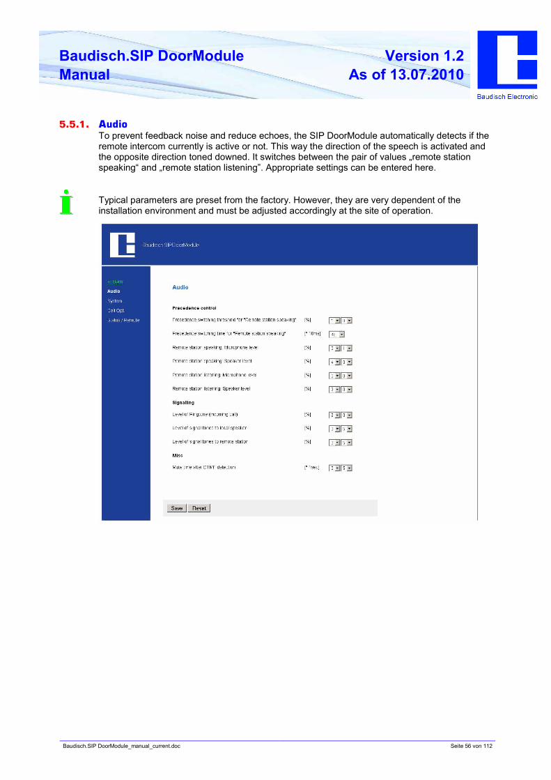
5.5.1. Audio
To prevent feedback noise and reduce echoes, the SIP DoorModule automatically detects if the
remote intercom currently is active or not. This way the direction of the speech is activated and
the opposite direction toned downed. It switches between the pair of values „remote station
speaking“ and „remote station listening”. Appropriate settings can be entered here.
Typical parameters are preset from the factory. However, they are very dependent of the
installation environment and must be adjusted accordingly at the site of operation.
Baudisch.SIP DoorModule_manual_current.doc Seite 57 von 112
Baudisch.SIP DoorModule
Manual
Version 1.2
As of 13.07.2010
Precedence control
Switching threshold for „remote station speaking“
Sensitivity of the switching to „remote station speaking”. Be aware that the volume while
speaking doesn’t stay constant.
Switching time for „remote station speaking“
Delay of the return switching when below the switching threshold.
Remote station speaking: microphone and speaker level
Microphone level and speaker level when the switching is active. Then the microphone level
should be lower than with “remote station listening” and the speaker level should be higher.
Remote station listening: microphone and speaker level
Microphone level and speaker level when the switching is not active. Then the speaker level
should be lower than with „remote station speaking” and the microphone level should be higher.
Signalling
Level of ring tone (incoming call)
The volume of the ring tone being played back. The dial and busy tones while dialling are
played back with half of the preset value.
Level to signal tones to local speaker
The volume of the signal tones which is heard by the person at the intercom (local). Included
are the button confirmation tones, the switchon tune and action confirmation (for example call
ended)
Level of signal tones to remote station
The setting decides the volume of the signalling tones which the person hears at the remote
station (DTMF confirmation, confirmation acknowledgement, door opener signalling and error
tone)
Miscellaneous
Mute time after DTMF detection
The speaker at the door module is switched to mute mode as soon as the second DTMF digit is
entered. When the code is correctly entered, the mute modus is immediately cancelled after the
positive confirmation. When an incorrect or an incomplete code is entered, the mute modus is
cancelled after the mute time.
Baudisch.SIP DoorModule_manual_current.doc Seite 58 von 112
Baudisch.SIP DoorModule
Manual
Version 1.2
As of 13.07.2010
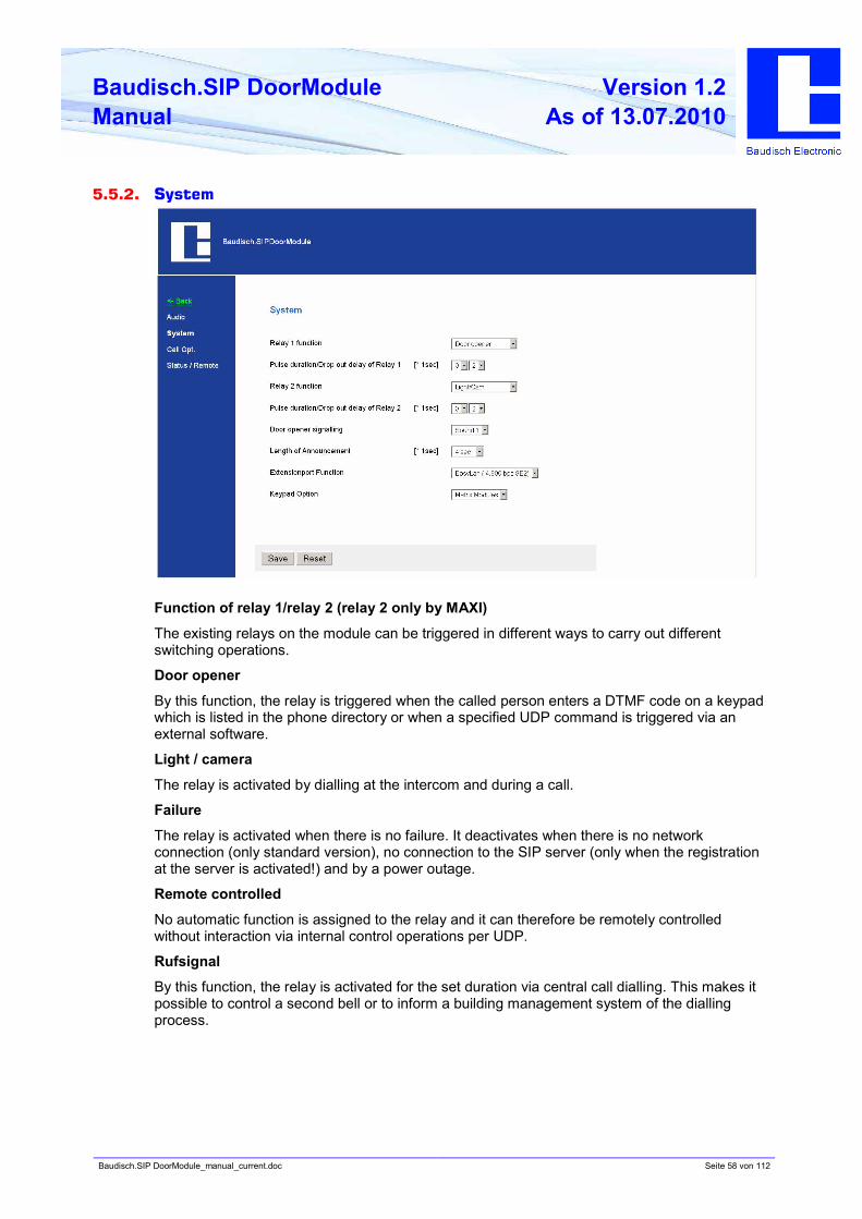
5.5.2. System
Function of relay 1/relay 2 (relay 2 only by MAXI)
The existing relays on the module can be triggered in different ways to carry out different
switching operations.
Door opener
By this function, the relay is triggered when the called person enters a DTMF code on a keypad
which is listed in the phone directory or when a specified UDP command is triggered via an
external software.
Light / camera
The relay is activated by dialling at the intercom and during a call.
Failure
The relay is activated when there is no failure. It deactivates when there is no network
connection (only standard version), no connection to the SIP server (only when the registration
at the server is activated!) and by a power outage.
Remote controlled
No automatic function is assigned to the relay and it can therefore be remotely controlled
without interaction via internal control operations per UDP.
Rufsignal
By this function, the relay is activated for the set duration via central call dialling. This makes it
possible to control a second bell or to inform a building management system of the dialling
process.
Baudisch.SIP DoorModule_manual_current.doc Seite 59 von 112
Baudisch.SIP DoorModule
Manual
Version 1.2
As of 13.07.2010
Pulse duration / Drop out delay of relay 1 (door) / relay 2 (light)
Depending on the assigned function, the setting is either a pulse duration (door opener) or a
drop out delay (light / camera). There is an immediate switch by the failure notification function
when a new condition is recognized. By the remote control is the preset pulse duration relevant.
Door opening signalling
The door opening signalling operates with the same principle as a blind traffic light. A tone
signal is heard as long as the door opener is pressed. It can for example be useful by the
application of a direct current voltage opener because there is no electro acoustics carried out.
Length of ID announcement
Here the length of the recorded announcement must be set.
Extensionport function
The extension port serves the connection of external add-on modules and intra-company
service purposes. An external add-on module could for example be a switch component, which
makes it possible to connect up to 115 ring buttons at the intercom.
Keypad option
This choice must be made when you would like to expand the door module with a „keypad“ or
matrix modules“.
The keypad option has no function by the DoorModule ECO version.
Baudisch.SIP DoorModule_manual_current.doc Seite 60 von 112
Baudisch.SIP DoorModule
Manual
Version 1.2
As of 13.07.2010
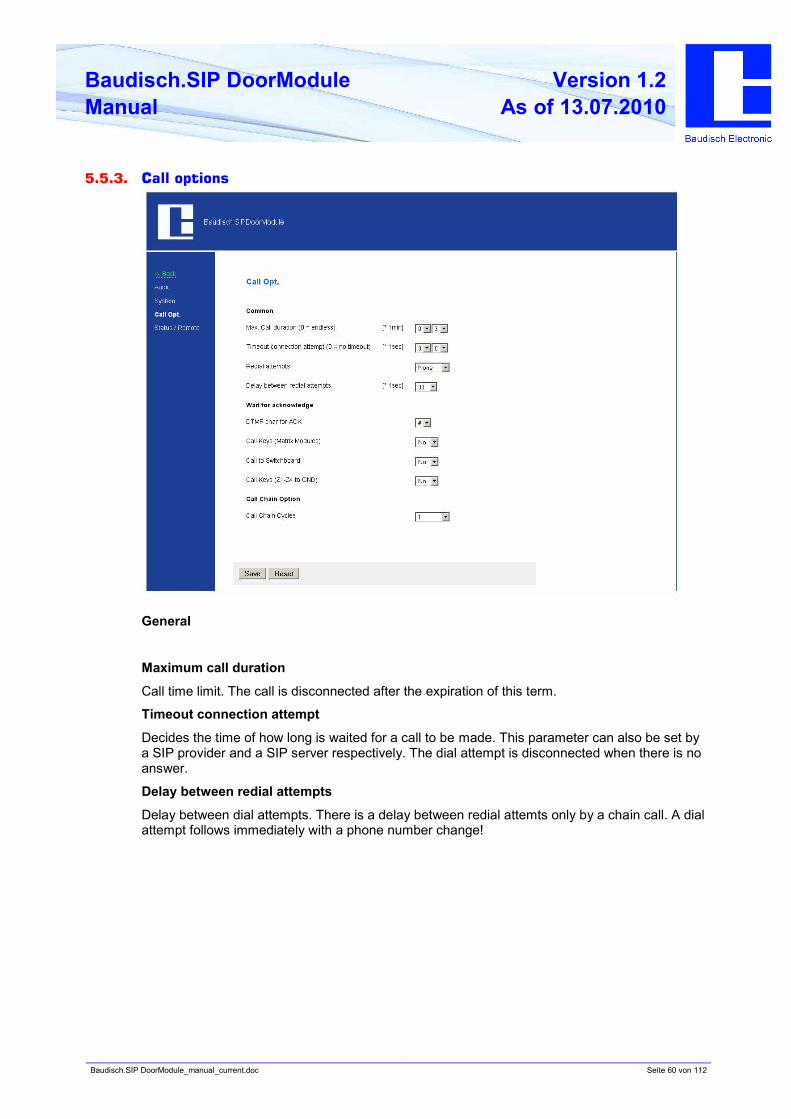
5.5.3. Call options
General
Maximum call duration
Call time limit. The call is disconnected after the expiration of this term.
Timeout connection attempt
Decides the time of how long is waited for a call to be made. This parameter can also be set by
a SIP provider and a SIP server respectively. The dial attempt is disconnected when there is no
answer.
Delay between redial attempts
Delay between dial attempts. There is a delay between redial attemts only by a chain call. A dial
attempt follows immediately with a phone number change!
Baudisch.SIP DoorModule_manual_current.doc Seite 61 von 112
Baudisch.SIP DoorModule
Manual
Version 1.2
As of 13.07.2010
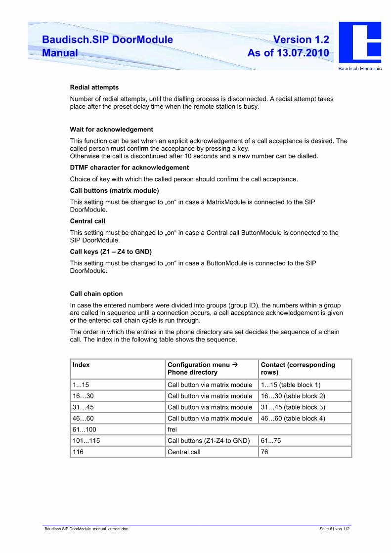
Redial attempts
Number of redial attempts, until the dialling process is disconnected. A redial attempt takes
place after the preset delay time when the remote station is busy.
Wait for acknowledgement
This function can be set when an explicit acknowledgement of a call acceptance is desired. The
called person must confirm the acceptance by pressing a key.
Otherwise the call is discontinued after 10 seconds and a new number can be dialled.
DTMF character for acknowledgement
Choice of key with which the called person should confirm the call acceptance.
Call buttons (matrix module)
This setting must be changed to „on“ in case a MatrixModule is connected to the SIP
DoorModule.
Central call
This setting must be changed to „on“ in case a Central call ButtonModule is connected to the
SIP DoorModule.
Call keys (Z1 – Z4 to GND)
This setting must be changed to „on“ in case a ButtonModule is connected to the SIP
DoorModule.
Call chain option
In case the entered numbers were divided into groups (group ID), the numbers within a group
are called in sequence until a connection occurs, a call acceptance acknowledgement is given
or the entered call chain cycle is run through.
The order in which the entries in the phone directory are set decides the sequence of a chain
call. The index in the following table shows the sequence.
Index Configuration menu à
Phone directory
Contact (corresponding
rows)
1...15 Call button via matrix module 1...15 (table block 1)
16…30 Call button via matrix module 16…30 (table block 2)
31…45 Call button via matrix module 31…45 (table block 3)
46…60 Call button via matrix module 46…60 (table block 4)
61...100 frei
101...115 Call buttons (Z1-Z4 to GND) 61...75
116 Central call 76
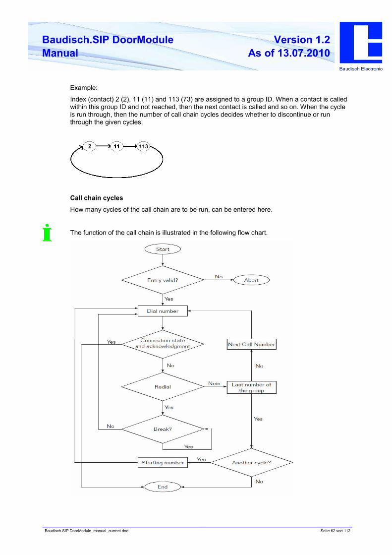
Baudisch.SIP DoorModule_manual_current.doc Seite 62 von 112
Baudisch.SIP DoorModule
Manual
Version 1.2
As of 13.07.2010
Example:
Index (contact) 2 (2), 11 (11) and 113 (73) are assigned to a group ID. When a contact is called
within this group ID and not reached, then the next contact is called and so on. When the cycle
is run through, then the number of call chain cycles decides whether to discontinue or run
through the given cycles.
Call chain cycles
How many cycles of the call chain are to be run, can be entered here.
The function of the call chain is illustrated in the following flow chart.
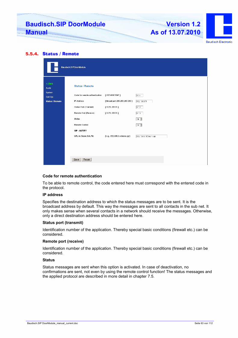
Baudisch.SIP DoorModule_manual_current.doc Seite 63 von 112
Baudisch.SIP DoorModule
Manual
Version 1.2
As of 13.07.2010
5.5.4. Status / Remote
Code for remote authentication
To be able to remote control, the code entered here must correspond with the entered code in
the protocol.
IP address
Specifies the destination address to which the status messages are to be sent. It is the
broadcast address by default. This way the messages are sent to all contacts in the sub net. It
only makes sense when several contacts in a network should receive the messages. Otherwise,
only a direct destination address should be entered here.
Status port (transmit)
Identification number of the application. Thereby special basic conditions (firewall etc.) can be
considered.
Remote port (receive)
Identification number of the application. Thereby special basic conditions (firewall etc.) can be
considered.
Status
Status messages are sent when this option is activated. In case of deactivation, no
confirmations are sent, not even by using the remote control function! The status messages and
the applied protocol are described in more detail in chapter 7.5.
Baudisch.SIP DoorModule_manual_current.doc Seite 64 von 112
Baudisch.SIP DoorModule
Manual
Version 1.2
As of 13.07.2010
Remote control
The relays of the SIP DoorModule can be operated by remote control over the network when
this function is activated. By the DoorModule MAXI, both camera IO’s can additionally be
controlled. The remote control operates indeed by activated remote control, however, without
activated status message, no confirmation will be sent on a remote command!
SIP NOTIFY
When a Baudisch.CP-CAM is connected to the DoorModule, the image of the corresponding
CAM can be shown by calls to a Snom 820 (VoIP phone). Therefore a separate file must be run
which is located on the Baudisch.CP-CAM. The path for the URL to the Snom-XML file must be
entered here.
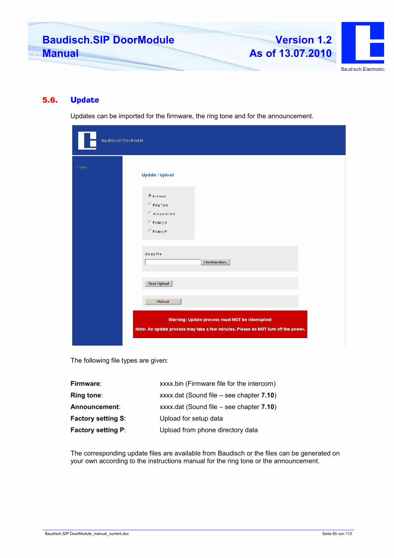
Baudisch.SIP DoorModule_manual_current.doc Seite 65 von 112
Baudisch.SIP DoorModule
Manual
Version 1.2
As of 13.07.2010
5.6. Update
Updates can be imported for the firmware, the ring tone and for the announcement.
The following file types are given:
Firmware: xxxx.bin (Firmware file for the intercom)
Ring tone: xxxx.dat (Sound file – see chapter 7.10)
Announcement: xxxx.dat (Sound file – see chapter 7.10)
Factory setting S: Upload for setup data
Factory setting P: Upload from phone directory data
The corresponding update files are available from Baudisch or the files can be generated on
your own according to the instructions manual for the ring tone or the announcement.
Baudisch.SIP DoorModule_manual_current.doc Seite 66 von 112
Baudisch.SIP DoorModule
Manual
Version 1.2
As of 13.07.2010
5.6.1. Firmware
The software of the SIP DoorModule can be updated by updating the firmware.
The update is available from Baudisch on request. Send us an e-mail with the product names
and serial numbers. We need this information in order to send you the applicable firmware. In
case you do not have the serial numbers, indicate the date of purchase.
E-mail : [email protected]
To keep the functions of the DoorModule warranted, an update of the AVR firmware should
follow an update of the firmware (see chapter 7.1 AVR firmware update).
To perform an update of the firmware.
1. Start the configuration menu (chapter 5.2).
2. Choose updates, enter password and login.
3. Choose firmware.
• File to be transferred: enter the path where the file xxx.bin from us is located.
• Start the transfer and wait until the automatic reset of the module, which is performed after
an update, is completed. (< 2Min.)
You have successfully undated the firmware.
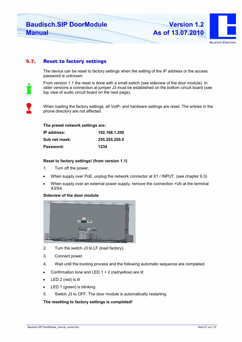
Baudisch.SIP DoorModule_manual_current.doc Seite 67 von 112
Baudisch.SIP DoorModule
Manual
Version 1.2
As of 13.07.2010
5.7. Reset to factory settings
The device can be reset to factory settings when the setting of the IP address or the access
password is unknown.
From version 1.1 the reset is done with a small switch (see sideview of the door module). In
older versions a connection at jumper J3 must be established on the bottom circuit board (see
top view of audio circuit board on the next page).
When loading the factory settings, all VoIP- and hardware settings are reset. The entries in the
phone directory are not affected.
The preset network settings are:
IP address: 192.168.1.200
Sub net mask: 255.255.255.0
Password: 1234
Reset to factory settings! (from version 1.1)
1. Turn off the power.
• When supply over PoE, unplug the network connector at X1 / INPUT. (see chapter 6.3)
• When supply over an external power supply, remove the connection +Ub at the terminal
X3/X4.
Sideview of the door module
2. Turn the switch J3 to LF (load factory).
3. Connect power.
4. Wait until the booting process and the following automatic sequence are completed.
• Confirmation tone and LED 1 + 2 (red/yellow) are lit
• LED 2 (red) is lit
• LED 1 (green) is blinking
5. Switch J3 to OFF. The door module is automatically restarting.
The resetting to factory settings is completed!
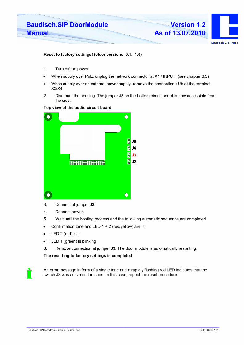
Baudisch.SIP DoorModule_manual_current.doc Seite 68 von 112
Baudisch.SIP DoorModule
Manual
Version 1.2
As of 13.07.2010
Reset to factory settings! (older versions 0.1...1.0)
1. Turn off the power.
• When supply over PoE, unplug the network connector at X1 / INPUT. (see chapter 6.3)
• When supply over an external power supply, remove the connection +Ub at the terminal
X3/X4.
2. Dismount the housing. The jumper J3 on the bottom circuit board is now accessible from
the side.
Top view of the audio circuit board
3. Connect at jumper J3.
4. Connect power.
5. Wait until the booting process and the following automatic sequence are completed.
• Confirmation tone and LED 1 + 2 (red/yellow) are lit
• LED 2 (red) is lit
• LED 1 (green) is blinking
6. Remove connection at jumper J3. The door module is automatically restarting.
The resetting to factory settings is completed!
An error message in form of a single tone and a rapidly flashing red LED indicates that the
switch J3 was activated too soon. In this case, repeat the reset procedure.
Baudisch.SIP DoorModule_manual_current.doc Seite 69 von 112
Baudisch.SIP DoorModule
Manual
Version 1.2
As of 13.07.2010
6. Product details
6.1. Technical data
Connections and interfaces
Ethernet with PoE à without external supply Ethernet over RJ45
10/100 Mbit/s
Ethernet without PoE à with external supply
Ethernet over RJ45 Integrated switch for direct connection of a CP-CAM
(only by the MAXI version)
Grounding
External supply (Ub, 0V), 24V DC 1A secured!
Relay (closer, dry contacts, max. loading 24V/2A) for door opener
Relay (closer, dry contacts, max. loading 24V/2A) for call display
alternatively useful for online monitoring (only by the MAXI version)
EasyLan (24V,Bus,GND) (only by the MAXI version)
Button (closer) (max. cable length to push button 0,5m)
Output illumination central call button ( for two coloured LED )
4 inputs for external, dry contact buttons for direct call triggering.
Binary codable for direct call to 15 contacts.
Screw type terminal
GND
Female connector
12 pin
Expansionport for diode matrix module (only by the MAXI version)
Baudisch.SIP DoorModule_manual_current.doc Seite 70 von 112
Baudisch.SIP DoorModule
Manual
Version 1.2
As of 13.07.2010
Physical characteristics
without Baudisch VA4 panel
(LxHxW) ca. 95 x 95 x 40 mm
Dimensions
with Baudisch VA4 panel
(WxHxW) ca. 109,5 x 109,5 x 43 mm
48 V by supply over PoE (Power over Ethernet) Operating voltage
24V DC (20-36V DC, 1A secured), by external supply
Power input Open-circuit operation: ca. 2,2W
Voice transmission: ca. 4W
Working temperature –20 to 50°C
(- 20°C after 15 min. operating time)
Environmental conditions
Protection class IP 65 up front for outdoor applications with
protection against splash water
Poke through protection by using the Baudisch V4A panel
Weight •• without Baudisch VA4 panel, ca. 320 g
•• with Baudisch VA4 panel, ca. 460g
Protection class IP65 in conjuction with a suitable housing
CE conform
EN 61000-4-4 Interference resistance against rapid transient interference
volumes. (Burst) Evaluation criterion: B
Limit/severity level: U=2KV/1KV, td= 15ms, tr=300ms, f=5KHz
EN 61000-4-2, EN 61000-
6-2, EN 50121-3-2
Interference resistance against electrostatic discharge. (ESD)
Evaluation criterion: B
Limit/severity level: air discharge 8 KV /contact entladung 6KV
EN 61000-4-5, EN 61000-
6-2, EN 50121-3-2
Interference resistance against surge voltage. (Surge)
Evaluation criterion: B
Limit/severity level: DM 0,5KV/ CM 0,5KV
EN 61000-4-6, EN 61000-
6-2, EN 50121-3-2
Interference resistance against conducted disturbances, induced
by high-frequency fields.
Limit/severity level: Coupling with 10V
EN 61000-4-3, EN61000-
6-2, EN50121-3-1
Interference resistance against high-frequency electromagnetic
fields. Limit/severity level: 70MHz bis 1GHz: 20V/m, 70 MHz bis
2GHz: 10V/m, 2GHz to 2,7 GHz: 3V/m, AM=80%, AF=1KHz.
EN 61000-6-3, EN55011,
EN 55022, EN 50121-3-2
Emission for residential, business and commercial areas, small
businesses as well as railway vehicles – and equipment.
Limit class B
Baudisch.SIP DoorModule_manual_current.doc Seite 71 von 112
Baudisch.SIP DoorModule
Manual
Version 1.2
As of 13.07.2010
Configuration, operating display
Integrated web server for configuration of all operating parameters and its internal phone
directory per network via a web browser.
In the MAXI version: 6 LEDsIlluminating diodes
indicating device status
In the ECO version: 5 LEDs
Miscellaneous
Network switch •• REALTEK RTL8305SC
•• Ethernet 10Base-T and 100Base-TX
•• Half duplex, full duplex
•• Auto negotiation
SIP RFC 2833 (DTMF), RFC2976 (SIP info)
Protocols SIP over 10/100 Mbit LAN, Ipv4, TCP, RTP, DHCP UDP, http, tftp,
easyLan, VLAN (IEEE 802.1pq)
Audio •• Built-in speaker RL=8Ohm/1W
Typ. power output=1,36W with RL= 8Ohm
Typ. power output =2,22W with RL= 4Ohm
Typ. power output =2,45W with RL= 3Ohm
•• Built-in hands-free microphone
•• Jitter buffer
Used audio codecs PCMU, PCMA, Speex, iLBC, G.726-32, GSM 6.10
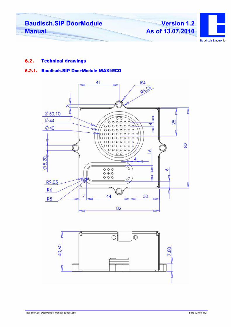
Baudisch.SIP DoorModule_manual_current.doc Seite 72 von 112
Baudisch.SIP DoorModule
Manual
Version 1.2
As of 13.07.2010
6.2. Technical drawings
6.2.1. Baudisch.SIP DoorModule MAXI/ECO
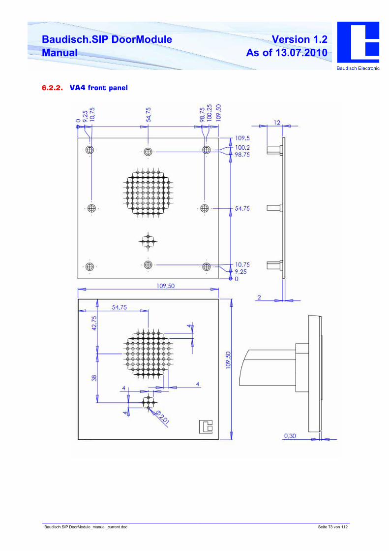
Baudisch.SIP DoorModule_manual_current.doc Seite 73 von 112
Baudisch.SIP DoorModule
Manual
Version 1.2
As of 13.07.2010
6.2.2. VA4 front panel
Baudisch.SIP DoorModule_manual_current.doc Seite 74 von 112
Baudisch.SIP DoorModule
Manual
Version 1.2
As of 13.07.2010
6.2.2.1 Installation instructions for V4A front panels
Risk of cutting injury on the back of the front panel!
By the installation of the VA4 front panel on the Baudisch.SIP DoorModule, be aware that the
surface of the front panel can be deformed when the screws are tightened too firmly. The
reason is the different hardness of the welded stud (VA2) and the front panel (VA4).
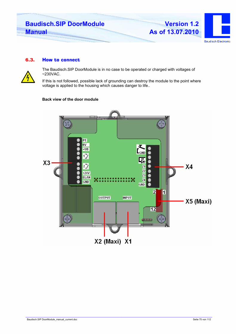
Baudisch.SIP DoorModule_manual_current.doc Seite 75 von 112
Baudisch.SIP DoorModule
Manual
Version 1.2
As of 13.07.2010
6.3. How to connect
The Baudisch.SIP DoorModule is in no case to be operated or charged with voltages of
~230VAC.
If this is not followed, possible lack of grounding can destroy the module to the point where
voltage is applied to the housing which causes danger to life..
Back view of the door module
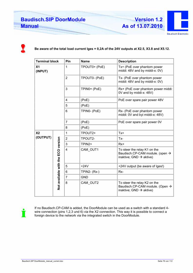
Baudisch.SIP DoorModule_manual_current.doc Seite 76 von 112
Baudisch.SIP DoorModule
Manual
Version 1.2
As of 13.07.2010
Be aware of the total load current Iges = 0,2A of the 24V outputs at X2.5, X3.8 and X5.12.
Terminal block Pin Name Description
1 TPOUT0+ (PoE) Tx+ (PoE over phantom power
middi: 48V and by middi-x: 0V)
2 TPOUT0- (PoE) Tx- (PoE over phantom power
middi: 48V and by middi-x: 0V)
3 TPIN0+ (PoE) Rx+ (PoE over phantom power middi:
0V and by middi-x: 48V)
4 (PoE)
5 (PoE)
PoE over spare pair power 48V
6 TPIN0- (PoE) Rx- (PoE over phantom power
middi: 0V and byi middi-x: 48V)
7 (PoE)
X1
(INPUT)
8 (PoE)
PoE over spare pair power 0V
1 TPOUT2+ Tx+
2 TPOUT2- Tx-
3 TPIN2+ Rx+
4 CAM_OUT1 To steer the relay K1 on the
Baudisch.CP-CAM module. (open à
inaktive; GND à aktive)
5 +24V +24V output (be aware of Iges!)
6 TPIN2- (Rx-) Rx-
7 GND
X2
(OUTPUT)
No
t a
vail
ab
le w
ith
th
e E
CO
vers
ion
8 CAM_OUT2 To steer the relay K2 on the
Baudisch.CP-CAM module. (Open à
inaktive; GND à aktive)
If no Baudisch.CP-CAM is added, the DoorModule can be used as a switch with a standard 4-
wire connection (pins 1,2,3 und 6) via the X2 connection. This way it is possible to connect a
foreign device to the network via the integrated switch in the DoorModule.
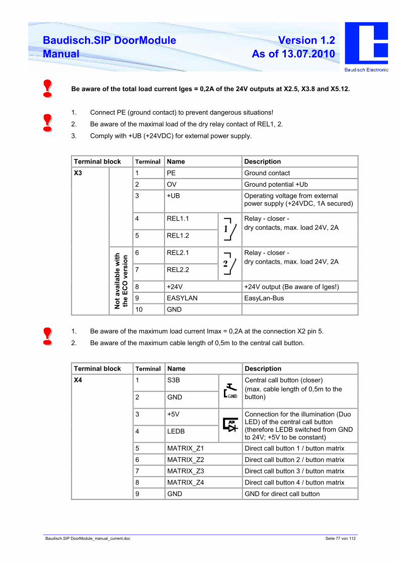
Baudisch.SIP DoorModule_manual_current.doc Seite 77 von 112
Baudisch.SIP DoorModule
Manual
Version 1.2
As of 13.07.2010
Be aware of the total load current Iges = 0,2A of the 24V outputs at X2.5, X3.8 and X5.12.
1. Connect PE (ground contact) to prevent dangerous situations!
2. Be aware of the maximal load of the dry relay contact of REL1, 2.
3. Comply with +UB (+24VDC) for external power supply.
Terminal block Terminal Name Description
1 PE Ground contact
2 OV Ground potential +Ub
der externen Versorgung (0V)
3 +UB Operating voltage from external
power supply (+24VDC, 1A secured)
4 REL1.1
5 REL1.2
Relay - closer -
dry contacts, max. load 24V, 2A
6 REL2.1
7 REL2.2
Relay - closer -
dry contacts, max. load 24V, 2A
8 +24V +24V output (Be aware of Iges!)
9 EASYLAN EasyLan-Bus
X3
No
t a
vail
ab
le w
ith
th
e E
CO
vers
ion
10 GND
1. Be aware of the maximum load current Imax = 0,2A at the connection X2 pin 5.
2. Be aware of the maximum cable length of 0,5m to the central call button.
Terminal block Terminal Name Description
1 S3B
2 GND
Central call button (closer)
(max. cable length of 0,5m to the
button)
3 +5V
4 LEDB
Connection for the illumination (Duo
LED) of the central call button
(therefore LEDB switched from GND
to 24V; +5V to be constant)
5 MATRIX_Z1 Direct call button 1 / button matrix
6 MATRIX_Z2 Direct call button 2 / button matrix
7 MATRIX_Z3 Direct call button 3 / button matrix
8 MATRIX_Z4 Direct call button 4 / button matrix
X4
9 GND GND for direct call button
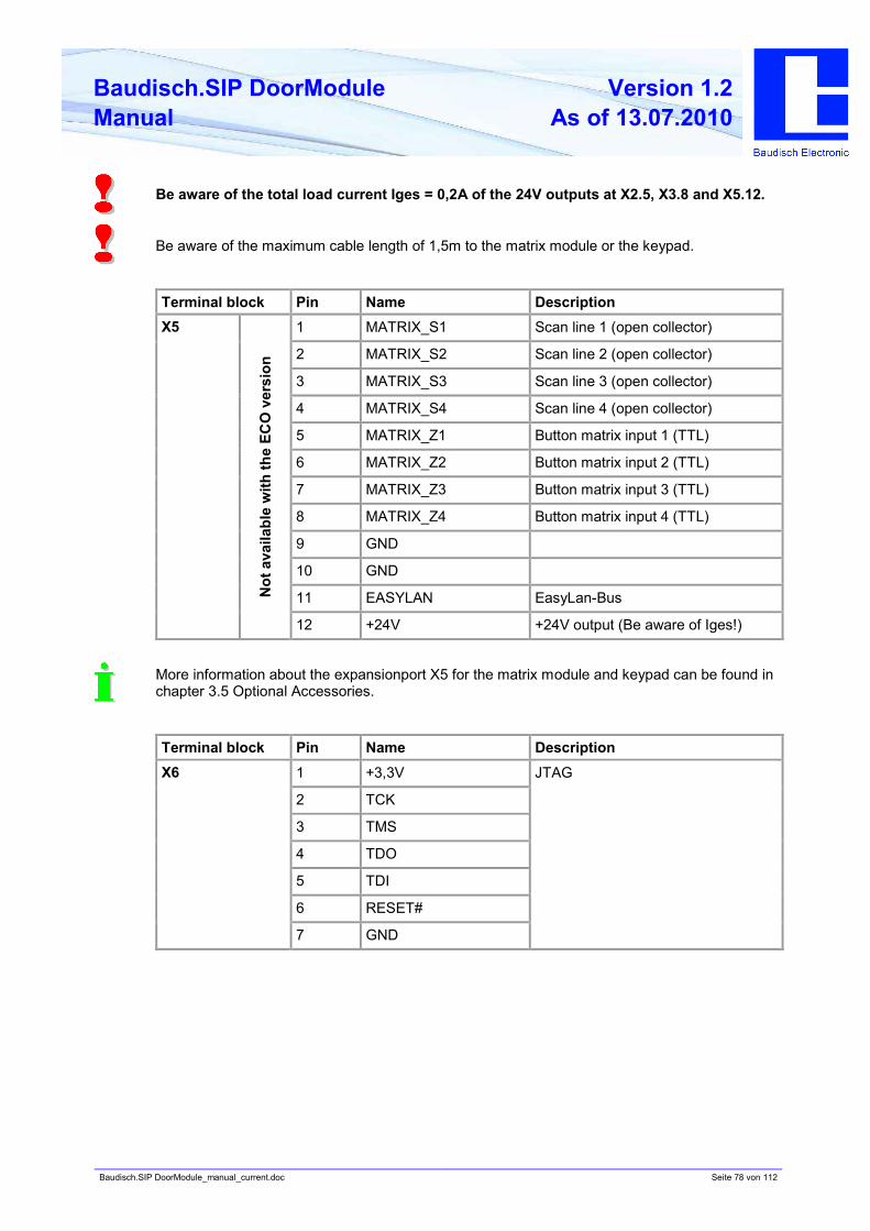
Baudisch.SIP DoorModule_manual_current.doc Seite 78 von 112
Baudisch.SIP DoorModule
Manual
Version 1.2
As of 13.07.2010
Be aware of the total load current Iges = 0,2A of the 24V outputs at X2.5, X3.8 and X5.12.
Be aware of the maximum cable length of 1,5m to the matrix module or the keypad.
Terminal block Pin Name Description
1 MATRIX_S1 Scan line 1 (open collector)
2 MATRIX_S2 Scan line 2 (open collector)
3 MATRIX_S3 Scan line 3 (open collector)
4 MATRIX_S4 Scan line 4 (open collector)
5 MATRIX_Z1 Button matrix input 1 (TTL)
6 MATRIX_Z2 Button matrix input 2 (TTL)
7 MATRIX_Z3 Button matrix input 3 (TTL)
8 MATRIX_Z4 Button matrix input 4 (TTL)
9 GND
10 GND
11 EASYLAN EasyLan-Bus
X5
No
t a
vail
ab
le w
ith
th
e E
CO
vers
ion
12 +24V +24V output (Be aware of Iges!)
More information about the expansionport X5 for the matrix module and keypad can be found in
chapter 3.5 Optional Accessories.
Terminal block Pin Name Description
1 +3,3V
2 TCK
3 TMS
4 TDO
5 TDI
6 RESET#
X6
7 GND
JTAG
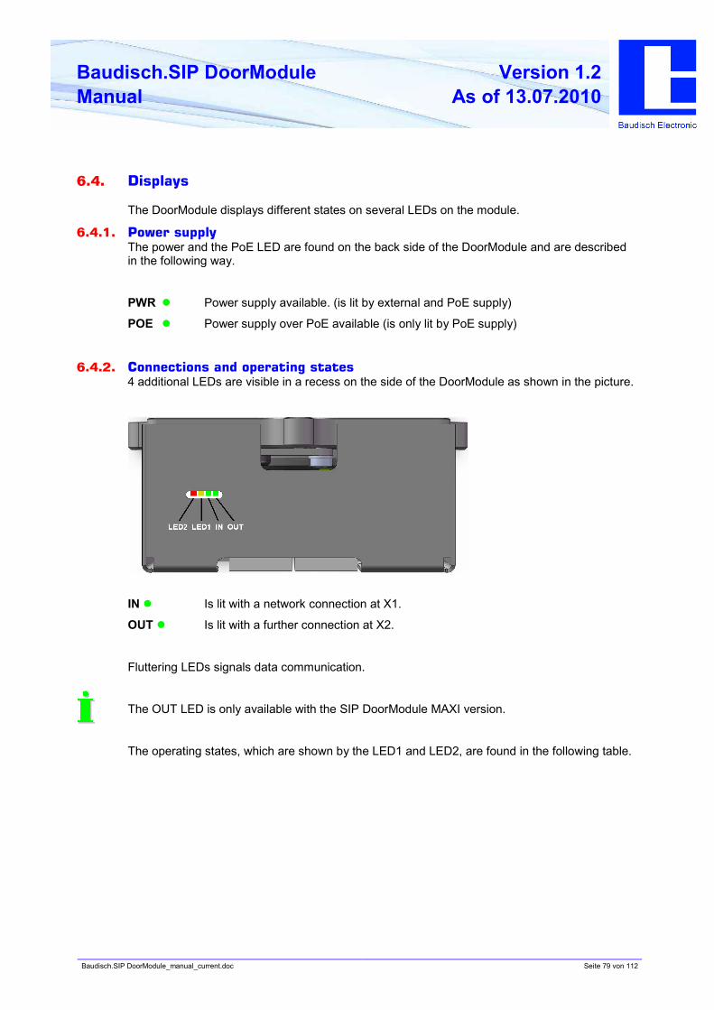
Baudisch.SIP DoorModule_manual_current.doc Seite 79 von 112
Baudisch.SIP DoorModule
Manual
Version 1.2
As of 13.07.2010
6.4. Displays
The DoorModule displays different states on several LEDs on the module.
6.4.1. Power supply
The power and the PoE LED are found on the back side of the DoorModule and are described
in the following way.
PWR l Power supply available. (is lit by external and PoE supply)
POE l Power supply over PoE available (is only lit by PoE supply)
6.4.2. Connections and operating states
4 additional LEDs are visible in a recess on the side of the DoorModule as shown in the picture.
IN l Is lit with a network connection at X1.
OUT l Is lit with a further connection at X2.
Fluttering LEDs signals data communication.
The OUT LED is only available with the SIP DoorModule MAXI version.
The operating states, which are shown by the LED1 and LED2, are found in the following table.
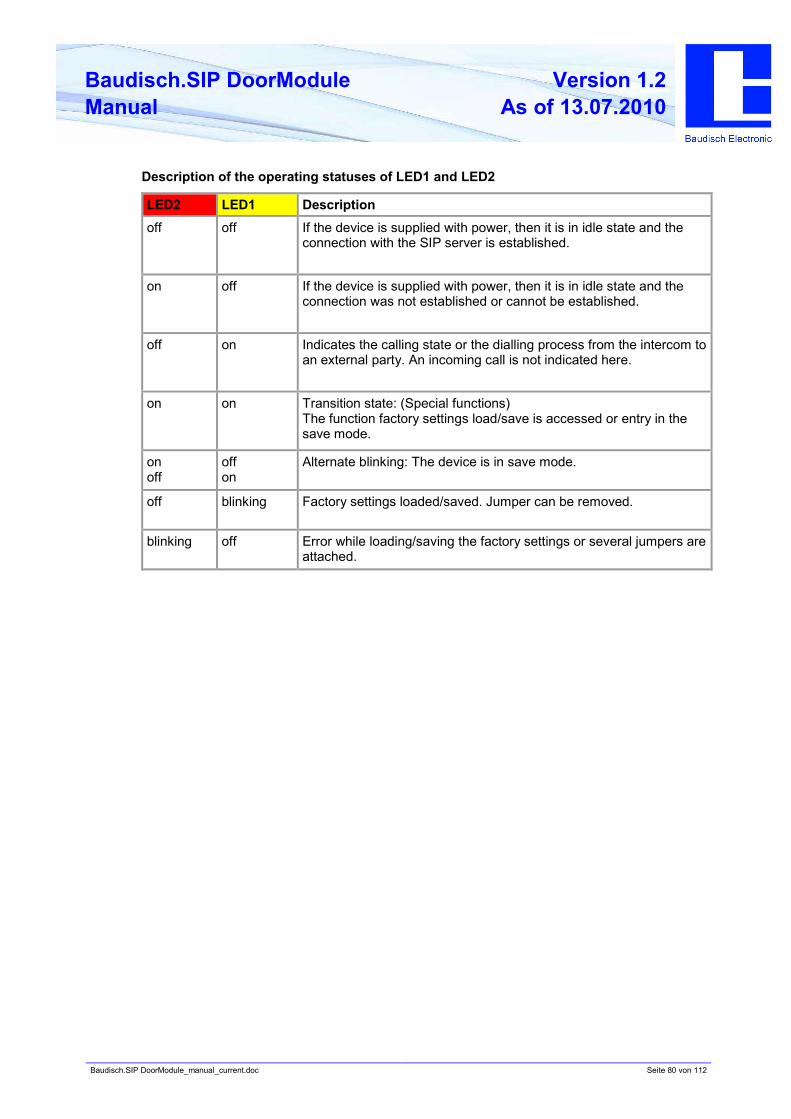
Baudisch.SIP DoorModule_manual_current.doc Seite 80 von 112
Baudisch.SIP DoorModule
Manual
Version 1.2
As of 13.07.2010
Description of the operating statuses of LED1 and LED2
LED2 LED1 Description
off off If the device is supplied with power, then it is in idle state and the
connection with the SIP server is established.
on off If the device is supplied with power, then it is in idle state and the
connection was not established or cannot be established.
off on Indicates the calling state or the dialling process from the intercom to
an external party. An incoming call is not indicated here.
on on Transition state: (Special functions)
The function factory settings load/save is accessed or entry in the
save mode.
on
off
off
on
Alternate blinking: The device is in save mode.
off blinking Factory settings loaded/saved. Jumper can be removed.
blinking off Error while loading/saving the factory settings or several jumpers are
attached.
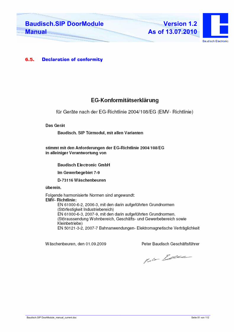
Baudisch.SIP DoorModule_manual_current.doc Seite 81 von 112
Baudisch.SIP DoorModule
Manual
Version 1.2
As of 13.07.2010
6.5. Declaration of conformity
Baudisch.SIP DoorModule_manual_current.doc Seite 82 von 112
Baudisch.SIP DoorModule
Manual
Version 1.2
As of 13.07.2010
7. Extras
7.1. AVR firmware update
An update of the AVR firmware is only recommended when you have previosly installed an
update for the DoorModule (see chapter 5.6.1).
A program („SIP Remote Control“) was developed, which enables an update of the firmware
over the network, without opening the device.
Why and when should the AVR firmware be updated?
To keep the functions of the DoorModule warranted, an update of the AVR firmware should be
made after an update of the firmware is performed.
How do I get the latest firmware and SIP Remote Control?
You receive the SIP Remote Control and the AVR firmware together with the e-mail, in which
the firmware for the DoorModule was sent on your request.
To perform an update of the AVR firmware via the boot loader function in SIP Remote
Control.
Before you can start the SIP Remote Control, the following configurations must be made in the
web interface of the DoorModule.
1. Start the configuration menu (chapter 5.2)
• Select hardware settings, enter password and login (Standardpasswort:1234).
2. Select status / remote control and enter the following settings.
• IP address: The IP address of the PC over which the firmware update is made should be
entered here. Otherwise, there is too much data communication in the network.
• Status port (send): 8112 (recommended)
• Remote control port (receive): 8113 (recommended)
• Status: „on“
• Remote control: „on“
3. Save
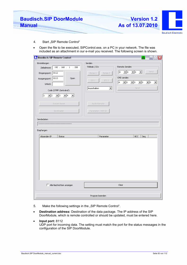
Baudisch.SIP DoorModule_manual_current.doc Seite 83 von 112
Baudisch.SIP DoorModule
Manual
Version 1.2
As of 13.07.2010
4. Start „SIP Remote Control“
• Open the file to be executed, SIPControl.exe, on a PC in your network. The file was
included as an attachment in our e-mail you received. The following screen is shown.
5. Make the following settings in the „SIP Remote Control“.
• Destination address: Destination of the data package. The IP address of the SIP
DoorModule, which is remote controlled or should be updated, must be entered here.
• Input port: 8112
UDP port for incoming data. The setting must match the port for the status messages in the
configuration of the SIP DoorModule.
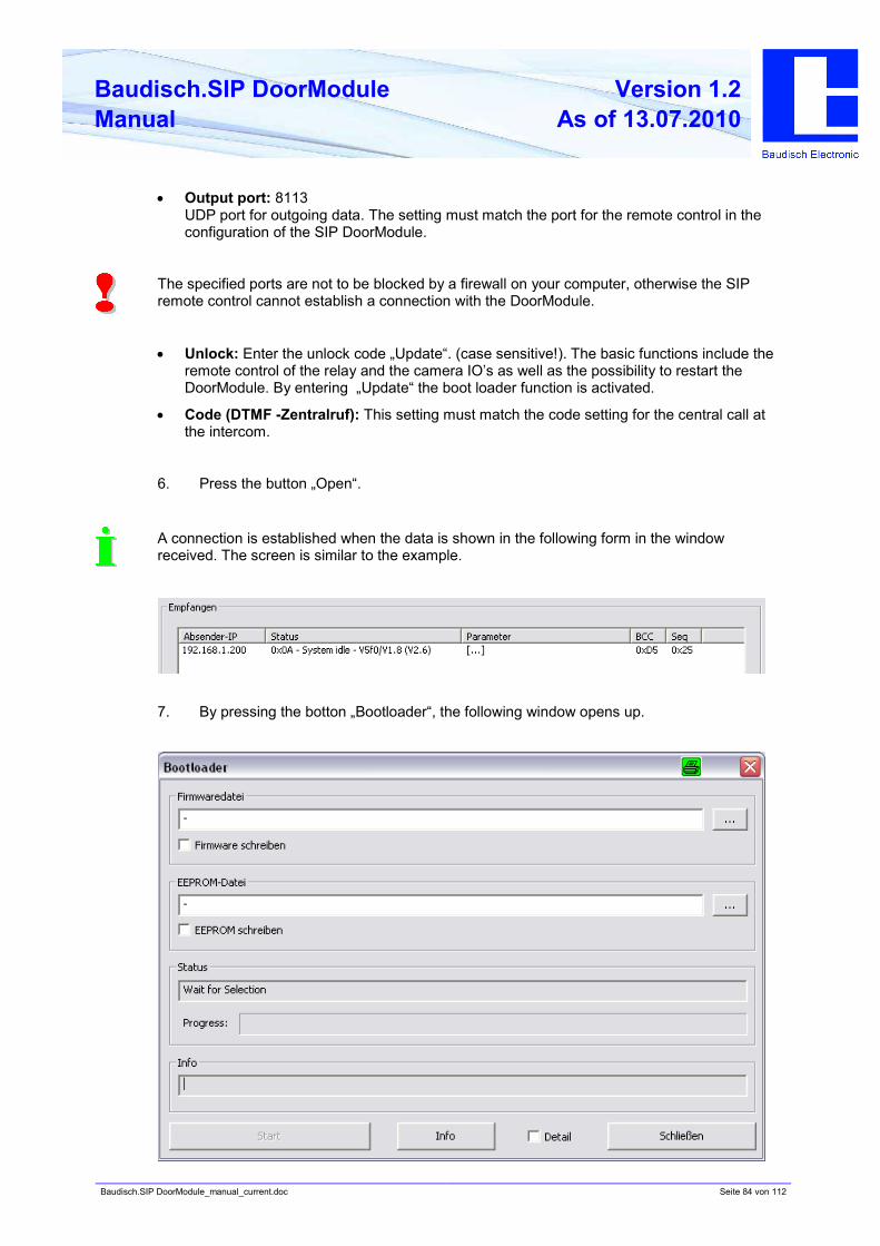
Baudisch.SIP DoorModule_manual_current.doc Seite 84 von 112
Baudisch.SIP DoorModule
Manual
Version 1.2
As of 13.07.2010
• Output port: 8113
UDP port for outgoing data. The setting must match the port for the remote control in the
configuration of the SIP DoorModule.
The specified ports are not to be blocked by a firewall on your computer, otherwise the SIP
remote control cannot establish a connection with the DoorModule.
• Unlock: Enter the unlock code „Update“. (case sensitive!). The basic functions include the
remote control of the relay and the camera IO’s as well as the possibility to restart the
DoorModule. By entering „Update“ the boot loader function is activated.
• Code (DTMF -Zentralruf): This setting must match the code setting for the central call at
the intercom.
6. Press the button „Open“.
A connection is established when the data is shown in the following form in the window
received. The screen is similar to the example.
7. By pressing the botton „Bootloader“, the following window opens up.
Baudisch.SIP DoorModule_manual_current.doc Seite 85 von 112
Baudisch.SIP DoorModule
Manual
Version 1.2
As of 13.07.2010
8. Enter the path of the file xxx.hex in the firmware file, which you have received as an e-
mail attachment.
9. Make a check at Firmware schreiben.
10. By pressing „Start“, the firmware is installed.
The process may take longer and is complete when „Operation successful” is shown in the
status field.
Reset the status and remote control in the web interface to „off“.
You have successfully completed the update of the AVR firmware.
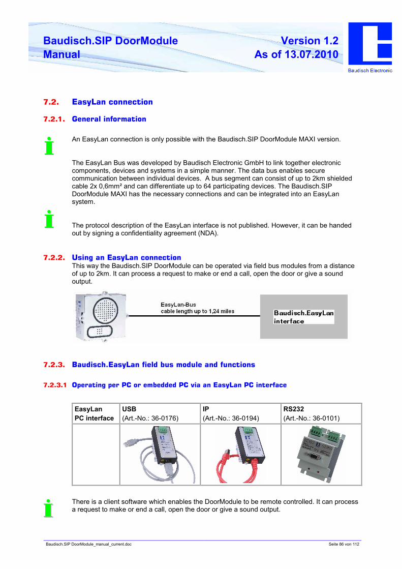
Baudisch.SIP DoorModule_manual_current.doc Seite 86 von 112
Baudisch.SIP DoorModule
Manual
Version 1.2
As of 13.07.2010
7.2. EasyLan connection
7.2.1. General information
An EasyLan connection is only possible with the Baudisch.SIP DoorModule MAXI version.
The EasyLan Bus was developed by Baudisch Electronic GmbH to link together electronic
components, devices and systems in a simple manner. The data bus enables secure
communication between individual devices. A bus segment can consist of up to 2km shielded
cable 2x 0,6mm² and can differentiate up to 64 participating devices. The Baudisch.SIP
DoorModule MAXI has the necessary connections and can be integrated into an EasyLan
system.
The protocol description of the EasyLan interface is not published. However, it can be handed
out by signing a confidentiality agreement (NDA).
7.2.2. Using an EasyLan connection
This way the Baudisch.SIP DoorModule can be operated via field bus modules from a distance
of up to 2km. It can process a request to make or end a call, open the door or give a sound
output.
7.2.3. Baudisch.EasyLan field bus module and functions
7.2.3.1 Operating per PC or embedded PC via an EasyLan PC interface
EasyLan
PC interface
USB
(Art.-No.: 36-0176)
IP
(Art.-No.: 36-0194)
RS232
(Art.-No.: 36-0101)
There is a client software which enables the DoorModule to be remote controlled. It can process
a request to make or end a call, open the door or give a sound output.
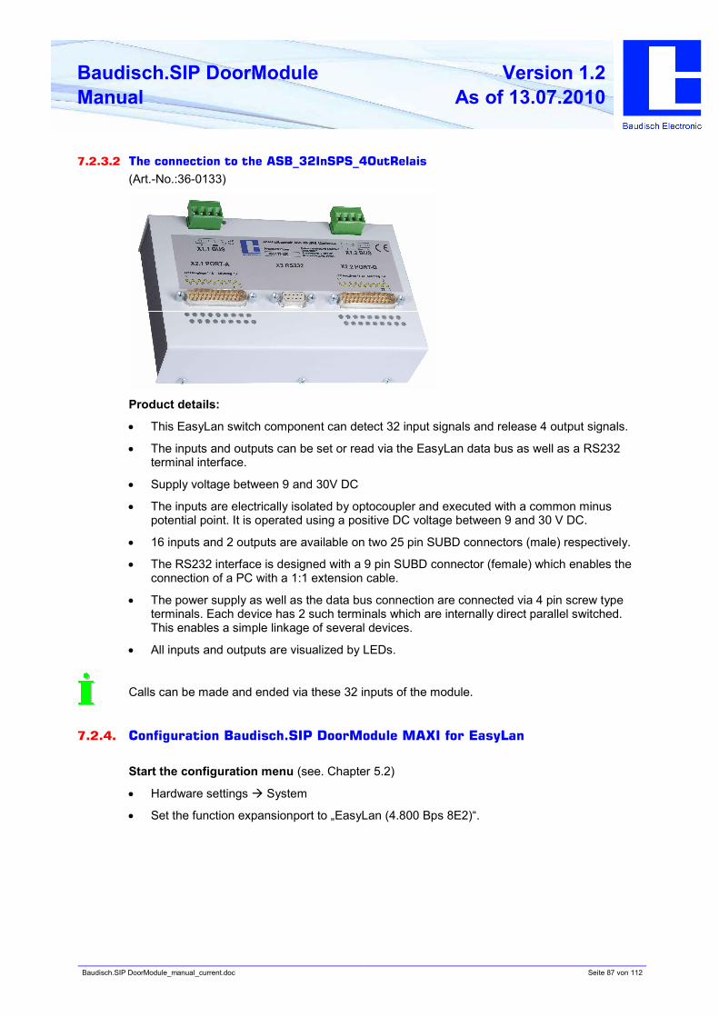
Baudisch.SIP DoorModule_manual_current.doc Seite 87 von 112
Baudisch.SIP DoorModule
Manual
Version 1.2
As of 13.07.2010
7.2.3.2 The connection to the ASB_32InSPS_4OutRelais
(Art.-No.:36-0133)
Product details:
• This EasyLan switch component can detect 32 input signals and release 4 output signals.
• The inputs and outputs can be set or read via the EasyLan data bus as well as a RS232
terminal interface.
• Supply voltage between 9 and 30V DC
• The inputs are electrically isolated by optocoupler and executed with a common minus
potential point. It is operated using a positive DC voltage between 9 and 30 V DC.
• 16 inputs and 2 outputs are available on two 25 pin SUBD connectors (male) respectively.
• The RS232 interface is designed with a 9 pin SUBD connector (female) which enables the
connection of a PC with a 1:1 extension cable.
• The power supply as well as the data bus connection are connected via 4 pin screw type
terminals. Each device has 2 such terminals which are internally direct parallel switched.
This enables a simple linkage of several devices.
• All inputs and outputs are visualized by LEDs.
Calls can be made and ended via these 32 inputs of the module.
7.2.4. Configuration Baudisch.SIP DoorModule MAXI for EasyLan
Start the configuration menu (see. Chapter 5.2)
• Hardware settings à System
• Set the function expansionport to „EasyLan (4.800 Bps 8E2)“.
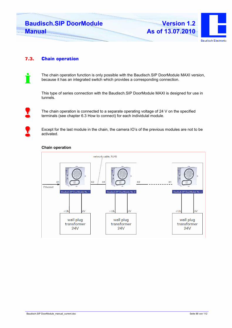
Baudisch.SIP DoorModule_manual_current.doc Seite 88 von 112
Baudisch.SIP DoorModule
Manual
Version 1.2
As of 13.07.2010
7.3. Chain operation
The chain operation function is only possible with the Baudisch.SIP DoorModule MAXI version,
because it has an integrated switch which provides a corresponding connection.
This type of series connection with the Baudisch.SIP DoorModule MAXI is designed for use in
tunnels.
The chain operation is connected to a separate operating voltage of 24 V on the specified
terminals (see chapter 6.3 How to connect) for each individulal module.
Except for the last module in the chain, the camera IO’s of the previous modules are not to be
activated.
Chain operation
Baudisch.SIP DoorModule_manual_current.doc Seite 89 von 112
Baudisch.SIP DoorModule
Manual
Version 1.2
As of 13.07.2010
7.4. Special functions
Different parameters in the EEPROM-Register can be read and overwritten via UDP. Due to the
change, special functions can be activated and configured which are not accessible over the
web interface.
7.4.1. Functions with the configuration parameters
7.4.1.1 Send a door opening code during a call
Parameter: SendDoorEnable (Address: 0x0603 / 1539d)
When this parameter is set to a value other than 0, a DTMF code from the phone directory can
be sent to the remote station during a call by pressing the UP button twice. As code is either the
code of the called person sent, or in case the call was made from the remote station, the code
of the identified participant or the code of the unknown caller.
7.4.1.2 Call logic
Parameter: CallAbortOptions (Adresse: 0x0602 / 1538d)
Value Function
0 Ending the dialling process und ending a call via any button possible.
1 Ending the dialling process und ending a call via any button blocked.
2 Ending the dialling process and ending a call via any other button than the one
used to dial possible.
3 Ending the dialling process and ending a call via any other button than the one
used to dial possible as well as the selection of a new number.
4...255 Works the same as for 0!
7.4.1.3 Button simulation
The activation of the following option of active simulation intervenes with the internal functional
logic making normal operation no longer possible. This option should therefore only be used by
specialized persons!
Parameter: TestOptions (Address: 0xFF1 / 4081d)
Bit 0=1 à Activation of the call button simulation for long term or load tests.
It simulates a keystroke according to the following parameters. With the delivery is bit 0=0
(deactivated).
The remaining 7 bits are not used.
Parameter: SwitchPattern (Address: 0xFF2 / 4082d)
Bit pattern with which the buttons are set to be simulated.
Bit 0 = SW_EXT1
Bit 1 = SW_EXT2
Bit 2 = SW_EXT3
Bit 3 = SW_EXT4
Bit 4 = UP
Bit 5 = DOWN
Bit 6 = OK
Bit 7 = no function
Baudisch.SIP DoorModule_manual_current.doc Seite 90 von 112
Baudisch.SIP DoorModule
Manual
Version 1.2
As of 13.07.2010
Not all combinations can be used, because the buttons UP, DOWN and
OK only individually make sense and the other 4 buttons only a a bit combination.
If all bits are set to 0 is no button pressed.
The value of the following 3 parameters must be between 1 and 255!
Parameter: SwitchOnTime (Address: 0xFF3 / 4083d)
Time, which should fit the bit pattern. The time is:
à Value * SwitchGranularity * 50ms
Parameter: SwitchPauseTime (Address: 0xFF4 / 4084d)
Time expected between the strokes. The time is:
à Value * SwitchGranularity * 50ms
Parameter: SwitchGranularity (Address: 0xFF5 / 4085d)
Unit of time for „SwitchOnTime“ und „SwitchPauseTime“.
7.4.1.4 Disconnect a call after remote relay
Parameter: RemoteCancelCall (Address: 0x0604 / 1540d)
Bit 0 = ending the dialling process
Bit 1 = disconnect a call
Bit 2 = always execute the function at remote relay 1
Bit 3 = always execute the function at remote relay 2
Bit 4 = no function
Bit 5 = no function
Bit 6 = no function
Bit 7 = no function
This function is used to end the dialling process or disconnects a call when the door opening
relay was activated via the UDP remote control. Each relay must be configured with the function
“door opener”. Otherwise, the function is only executed when bit 2 or bit 3 is set.
Baudisch.SIP DoorModule_manual_current.doc Seite 91 von 112
Baudisch.SIP DoorModule
Manual
Version 1.2
As of 13.07.2010
7.4.1.5 Activation of the DTMF relay selection
Parameter: EnableDTMFDoorSelect (Address: 0x0605 / 1541d)
If this parameter is set to a value other than 0, then the relay to be used can be selected with
the code sequence „*99n#“ giving n one of the following values:
0 = Both relays (always with a new connection or after DTMF timeout )
1 = only switch relay 1
2 = only switch relay 2
The actual door opening code must be sent immediately after the selection sequence, otherwise
the selection value is reset due to the timeout.
Also when the function is activated, the door code can still be entered alone (without
preselection „*99n#“).
Baudisch.SIP DoorModule_manual_current.doc Seite 92 von 112
Baudisch.SIP DoorModule
Manual
Version 1.2
As of 13.07.2010
7.4.2. Read or write the configuration parameters
These parameters can be changed with the software „SIP Remote Control“ from Baudisch
Electronic. You receive the software on request.
E-mail : [email protected]
Read or write parameters with SIP Remote Control.
Before you can start SIP Remote Control, the following configurations must be made on the
web interface of the DoorModule.
1. Start the configuration menu (Kapitel 5.2)
• Choose hardware settings, enter password eingeben and login. (Standard password: 1234)
2. Choose status / remote control and select the following settings.
• IP address: Here the IP address of the PC should be entered over which the parameters
are changed.
• Status port (send): 8112 (recommended)
• Remote control port (receive): 8113 (recommended)
• Status: „on“
• Remote control: „on“
3. Save
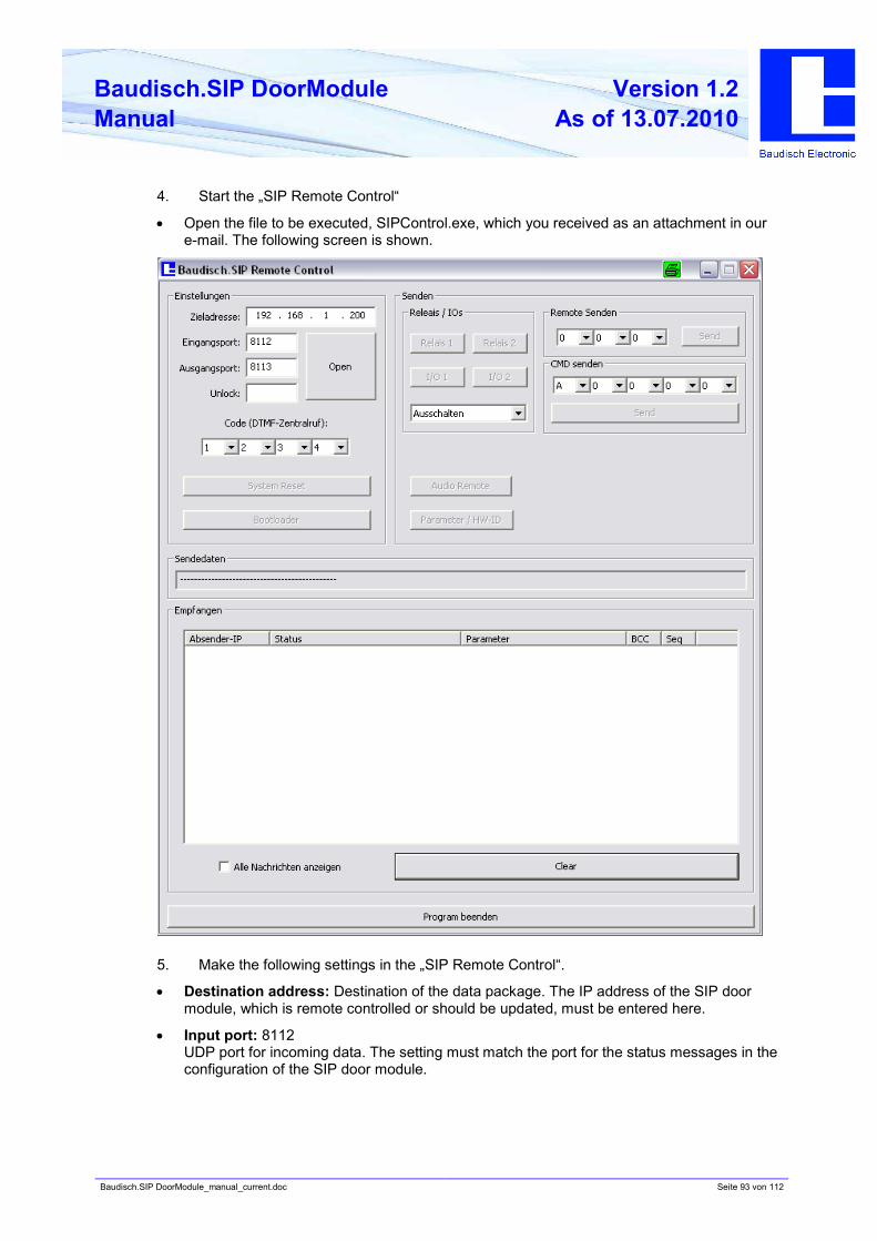
Baudisch.SIP DoorModule_manual_current.doc Seite 93 von 112
Baudisch.SIP DoorModule
Manual
Version 1.2
As of 13.07.2010
4. Start the „SIP Remote Control“
• Open the file to be executed, SIPControl.exe, which you received as an attachment in our
e-mail. The following screen is shown.
5. Make the following settings in the „SIP Remote Control“.
• Destination address: Destination of the data package. The IP address of the SIP door
module, which is remote controlled or should be updated, must be entered here.
• Input port: 8112
UDP port for incoming data. The setting must match the port for the status messages in the
configuration of the SIP door module.
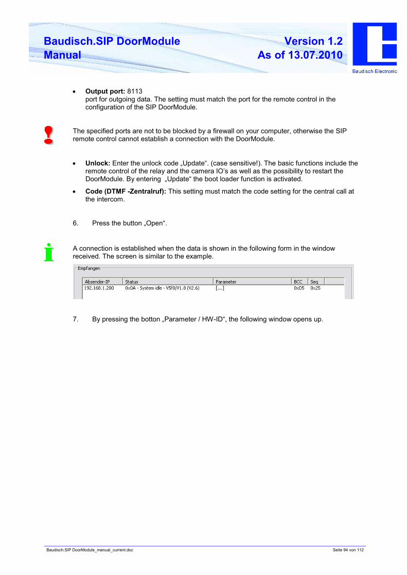
Baudisch.SIP DoorModule_manual_current.doc Seite 94 von 112
Baudisch.SIP DoorModule
Manual
Version 1.2
As of 13.07.2010
• Output port: 8113
port for outgoing data. The setting must match the port for the remote control in the
configuration of the SIP DoorModule.
The specified ports are not to be blocked by a firewall on your computer, otherwise the SIP
remote control cannot establish a connection with the DoorModule.
• Unlock: Enter the unlock code „Update“. (case sensitive!). The basic functions include the
remote control of the relay and the camera IO’s as well as the possibility to restart the
DoorModule. By entering „Update“ the boot loader function is activated.
• Code (DTMF -Zentralruf): This setting must match the code setting for the central call at
the intercom.
6. Press the button „Open“.
A connection is established when the data is shown in the following form in the window
received. The screen is similar to the example.
7. By pressing the botton „Parameter / HW-ID“, the following window opens up.
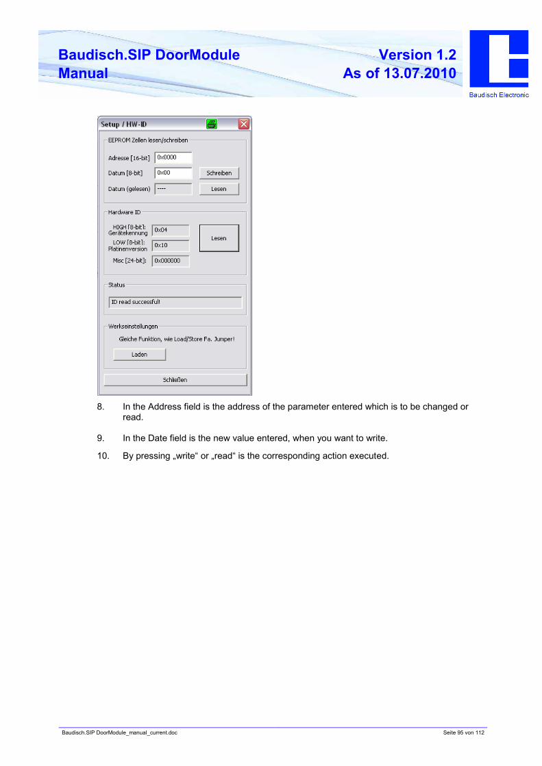
Baudisch.SIP DoorModule_manual_current.doc Seite 95 von 112
Baudisch.SIP DoorModule
Manual
Version 1.2
As of 13.07.2010
8. In the Address field is the address of the parameter entered which is to be changed or
read.
9. In the Date field is the new value entered, when you want to write.
10. By pressing „write“ or „read“ is the corresponding action executed.
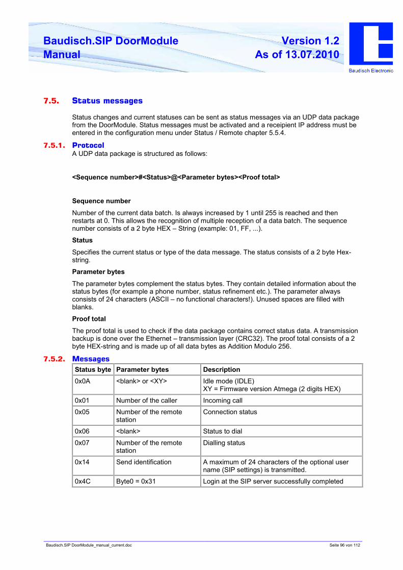
Baudisch.SIP DoorModule_manual_current.doc Seite 96 von 112
Baudisch.SIP DoorModule
Manual
Version 1.2
As of 13.07.2010
7.5. Status messages
Status changes and current statuses can be sent as status messages via an UDP data package
from the DoorModule. Status messages must be activated and a receipient IP address must be
entered in the configuration menu under Status / Remote chapter 5.5.4.
7.5.1. Protocol
A UDP data package is structured as follows:
<Sequence number>#<Status>@<Parameter bytes><Proof total>
Sequence number
Number of the current data batch. Is always increased by 1 until 255 is reached and then
restarts at 0. This allows the recognition of multiple reception of a data batch. The sequence
number consists of a 2 byte HEX – String (example: 01, FF, ...).
Status
Specifies the current status or type of the data message. The status consists of a 2 byte Hex-
string.
Parameter bytes
The parameter bytes complement the status bytes. They contain detailed information about the
status bytes (for example a phone number, status refinement etc.). The parameter always
consists of 24 characters (ASCII – no functional characters!). Unused spaces are filled with
blanks.
Proof total
The proof total is used to check if the data package contains correct status data. A transmission
backup is done over the Ethernet – transmission layer (CRC32). The proof total consists of a 2
byte HEX-string and is made up of all data bytes as Addition Modulo 256.
7.5.2. Messages
Status byte Parameter bytes Description
0x0A <blank> or <XY> Idle mode (IDLE)
XY = Firmware version Atmega (2 digits HEX)
0x01 Number of the caller Incoming call
0x05 Number of the remote
station
Connection status
0x06 <blank> Status to dial
0x07 Number of the remote
station
Dialling status
0x14 Send identification A maximum of 24 characters of the optional user
name (SIP settings) is transmitted.
0x4C Byte0 = 0x31 Login at the SIP server successfully completed
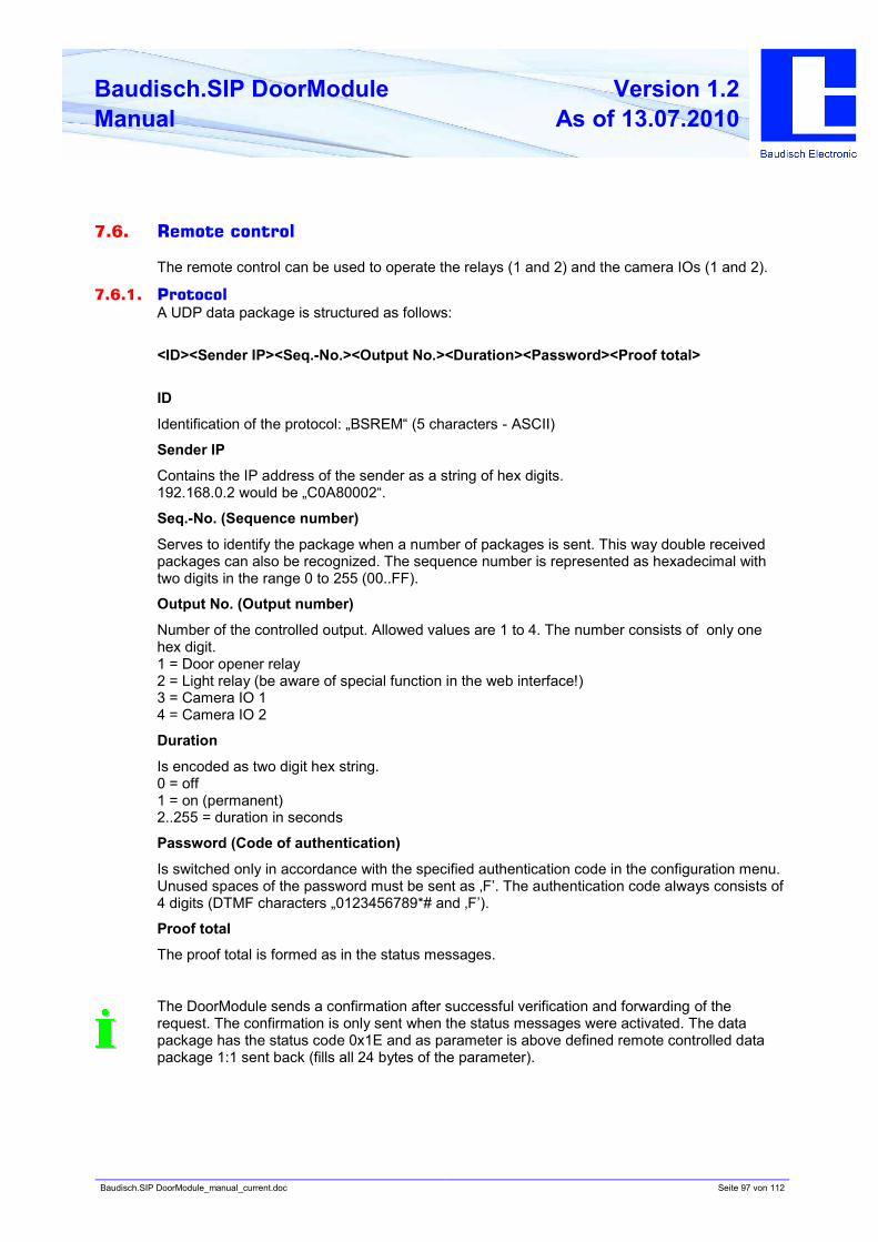
Baudisch.SIP DoorModule_manual_current.doc Seite 97 von 112
Baudisch.SIP DoorModule
Manual
Version 1.2
As of 13.07.2010
7.6. Remote control
The remote control can be used to operate the relays (1 and 2) and the camera IOs (1 and 2).
7.6.1. Protocol
A UDP data package is structured as follows:
<ID><Sender IP><Seq.-No.><Output No.><Duration><Password><Proof total>
ID
Identification of the protocol: „BSREM“ (5 characters - ASCII)
Sender IP
Contains the IP address of the sender as a string of hex digits.
192.168.0.2 would be „C0A80002“.
Seq.-No. (Sequence number)
Serves to identify the package when a number of packages is sent. This way double received
packages can also be recognized. The sequence number is represented as hexadecimal with
two digits in the range 0 to 255 (00..FF).
Output No. (Output number)
Number of the controlled output. Allowed values are 1 to 4. The number consists of only one
hex digit.
1 = Door opener relay
2 = Light relay (be aware of special function in the web interface!)
3 = Camera IO 1
4 = Camera IO 2
Duration
Is encoded as two digit hex string.
0 = off
1 = on (permanent)
2..255 = duration in seconds
Password (Code of authentication)
Is switched only in accordance with the specified authentication code in the configuration menu.
Unused spaces of the password must be sent as ‚F’. The authentication code always consists of
4 digits (DTMF characters „0123456789*# and ‚F’).
Proof total
The proof total is formed as in the status messages.
The DoorModule sends a confirmation after successful verification and forwarding of the
request. The confirmation is only sent when the status messages were activated. The data
package has the status code 0x1E and as parameter is above defined remote controlled data
package 1:1 sent back (fills all 24 bytes of the parameter).
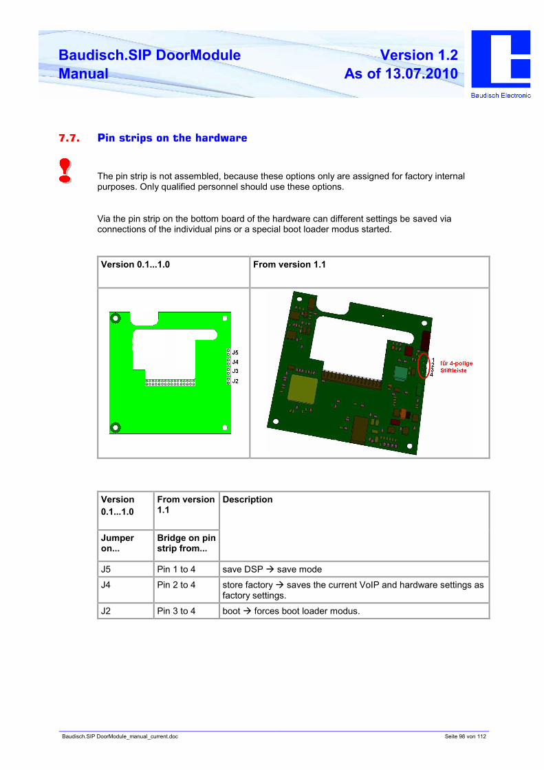
Baudisch.SIP DoorModule_manual_current.doc Seite 98 von 112
Baudisch.SIP DoorModule
Manual
Version 1.2
As of 13.07.2010
7.7. Pin strips on the hardware
The pin strip is not assembled, because these options only are assigned for factory internal
purposes. Only qualified personnel should use these options.
Via the pin strip on the bottom board of the hardware can different settings be saved via
connections of the individual pins or a special boot loader modus started.
Version 0.1...1.0 From version 1.1
Version
0.1...1.0
From version
1.1
Jumper
on...
Bridge on pin
strip from...
Description
J5 Pin 1 to 4 save DSP à save mode
J4 Pin 2 to 4 store factory à saves the current VoIP and hardware settings as
factory settings.
J2 Pin 3 to 4 boot à forces boot loader modus.
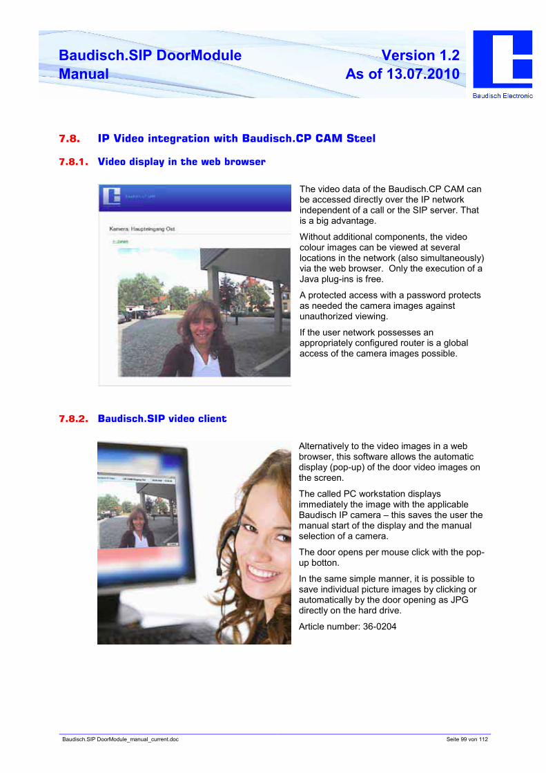
Baudisch.SIP DoorModule_manual_current.doc Seite 99 von 112
Baudisch.SIP DoorModule
Manual
Version 1.2
As of 13.07.2010
7.8. IP Video integration with Baudisch.CP CAM Steel
7.8.1. Video display in the web browser
The video data of the Baudisch.CP CAM can
be accessed directly over the IP network
independent of a call or the SIP server. That
is a big advantage.
Without additional components, the video
colour images can be viewed at several
locations in the network (also simultaneously)
via the web browser. Only the execution of a
Java plug-ins is free.
A protected access with a password protects
as needed the camera images against
unauthorized viewing.
If the user network possesses an
appropriately configured router is a global
access of the camera images possible.
7.8.2. Baudisch.SIP video client
Alternatively to the video images in a web
browser, this software allows the automatic
display (pop-up) of the door video images on
the screen.
The called PC workstation displays
immediately the image with the applicable
Baudisch IP camera – this saves the user the
manual start of the display and the manual
selection of a camera.
The door opens per mouse click with the pop-
up botton.
In the same simple manner, it is possible to
save individual picture images by clicking or
automatically by the door opening as JPG
directly on the hard drive.
Article number: 36-0204
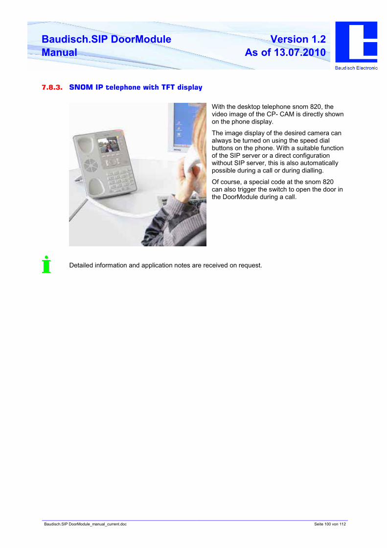
Baudisch.SIP DoorModule_manual_current.doc Seite 100 von 112
Baudisch.SIP DoorModule
Manual
Version 1.2
As of 13.07.2010
7.8.3. SNOM IP telephone with TFT display
With the desktop telephone snom 820, the
video image of the CP- CAM is directly shown
on the phone display.
The image display of the desired camera can
always be turned on using the speed dial
buttons on the phone. With a suitable function
of the SIP server or a direct configuration
without SIP server, this is also automatically
possible during a call or during dialling.
Of course, a special code at the snom 820
can also trigger the switch to open the door in
the DoorModule during a call.
Detailed information and application notes are received on request.
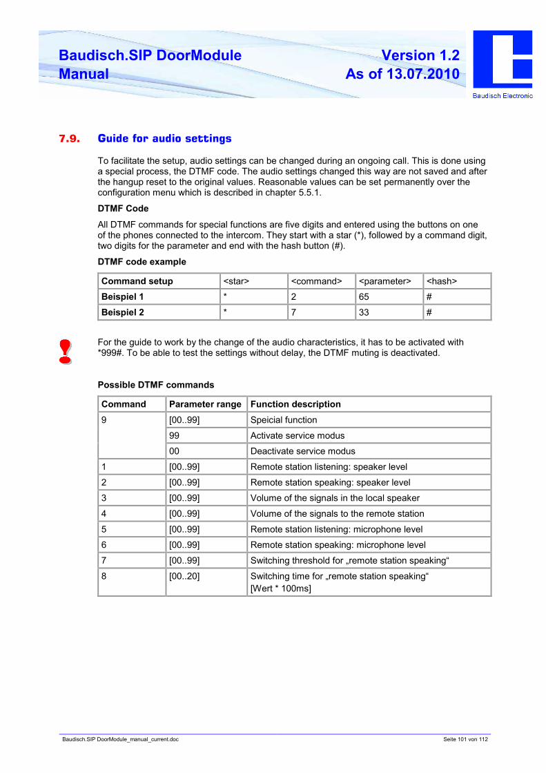
Baudisch.SIP DoorModule_manual_current.doc Seite 101 von 112
Baudisch.SIP DoorModule
Manual
Version 1.2
As of 13.07.2010
7.9. Guide for audio settings
To facilitate the setup, audio settings can be changed during an ongoing call. This is done using
a special process, the DTMF code. The audio settings changed this way are not saved and after
the hangup reset to the original values. Reasonable values can be set permanently over the
configuration menu which is described in chapter 5.5.1.
DTMF Code
All DTMF commands for special functions are five digits and entered using the buttons on one
of the phones connected to the intercom. They start with a star (*), followed by a command digit,
two digits for the parameter and end with the hash button (#).
DTMF code example
Command setup <star> <command> <parameter> <hash>
Beispiel 1 * 2 65 #
Beispiel 2 * 7 33 #
For the guide to work by the change of the audio characteristics, it has to be activated with
*999#. To be able to test the settings without delay, the DTMF muting is deactivated.
Possible DTMF commands
Command Parameter range Function description
[00..99] Speicial function
99 Activate service modus
9
00 Deactivate service modus
1 [00..99] Remote station listening: speaker level
2 [00..99] Remote station speaking: speaker level
3 [00..99] Volume of the signals in the local speaker
4 [00..99] Volume of the signals to the remote station
5 [00..99] Remote station listening: microphone level
6 [00..99] Remote station speaking: microphone level
7 [00..99] Switching threshold for „remote station speaking“
8 [00..20] Switching time for „remote station speaking“
[Wert * 100ms]
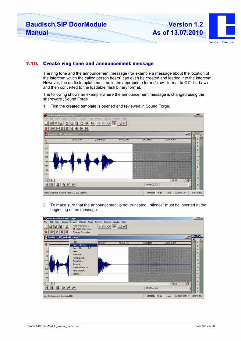
Baudisch.SIP DoorModule_manual_current.doc Seite 102 von 112
Baudisch.SIP DoorModule
Manual
Version 1.2
As of 13.07.2010
7.10. Create ring tone and announcement message
The ring tone and the announcement message (for example a message about the location of
the intercom which the called person hears) can even be created and loaded into the intercom.
However, the audio template must be in the appropriate form (*.raw –format to G711 u-Law)
and then converted to the loadable flash binary format.
The following shows an example where the announcement message is changed using the
shareware „Sound Forge“.
1. First the created template is opened and reviewed in Sound Forge.
2. To make sure that the announcement is not truncated, „silence“ must be inserted at the
beginning of the message.

Baudisch.SIP DoorModule_manual_current.doc Seite 103 von 112
Baudisch.SIP DoorModule
Manual
Version 1.2
As of 13.07.2010
3. The inserted silence should be appr. 1,5 to 2 seconds.......
.....and look like this after successful insertion.
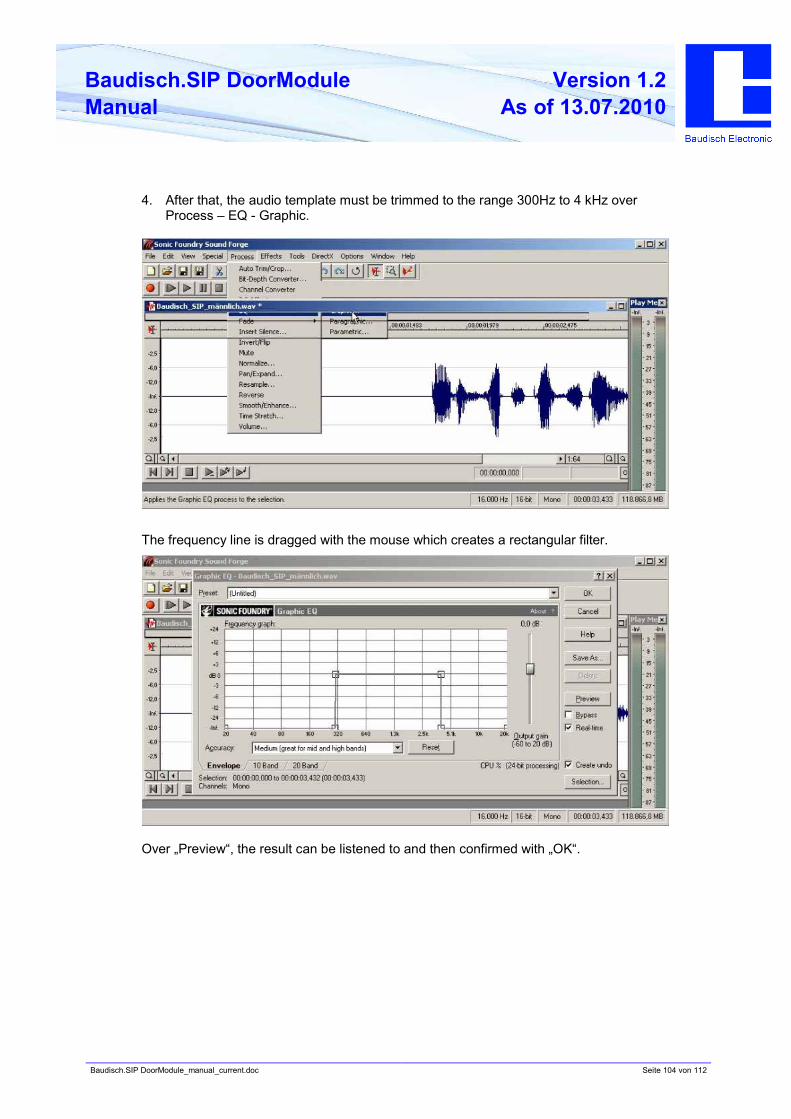
Baudisch.SIP DoorModule_manual_current.doc Seite 104 von 112
Baudisch.SIP DoorModule
Manual
Version 1.2
As of 13.07.2010
4. After that, the audio template must be trimmed to the range 300Hz to 4 kHz over
Process – EQ - Graphic.
The frequency line is dragged with the mouse which creates a rectangular filter.
Over „Preview“, the result can be listened to and then confirmed with „OK“.
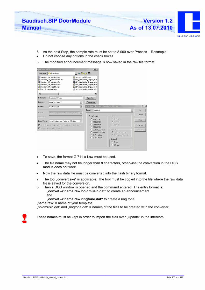
Baudisch.SIP DoorModule_manual_current.doc Seite 105 von 112
Baudisch.SIP DoorModule
Manual
Version 1.2
As of 13.07.2010
5. As the next Step, the sample rate must be set to 8.000 over Process – Resample.
• Do not choose any options in the check boxes.
6. The modified announcement message is now saved in the raw file format.
• To save, the format G.711 u-Law must be used.
• The file name may not be longer than 8 characters, otherwise the conversion in the DOS
modus does not work.
• Now the raw data file must be converted into the flash binary format.
7. The tool „convert.exe“ is applicable. The tool must be copied into the file where the raw data
file is saved for the conversion.
8. Then a DOS window is opened and the command entered. The entry format is:
„convet –r name.raw holdmusic.dat“ to create an announcement
and
„convet –r name.raw ringtone.dat“ to create a ring tone
„name.raw“ = name of your template
„holdmusic.dat“ and „ringtone.dat“ = names of the files to be created with the converter.
These names must be kept in order to import the files over „Update“ in the intercom.
Baudisch.SIP DoorModule_manual_current.doc Seite 106 von 112
Baudisch.SIP DoorModule
Manual
Version 1.2
As of 13.07.2010
8. FAQ
Which methods of DTMF transmission can be used?
There are 3 ways of transmission!
1. Inband audio method over RTP
A DTMF tone is created by pressing a button and coded via the set audio codec and then
transmitted as payload (voice data) in the RTP package.
2. SIP INFO method over SIP (RFC2976)
The information that a button pressed during a SIP session is transmitted as info
message in the SIP data package.
3. DTMF event method over RTP (RFC2833)
The information that a button pressed during a SIP session is recognized as DTMF event
and is transmitted as payload in a separate RTP data package.
Cause of error, when dialling is not possible? (disconnection shortly after activation)
There can be different reasons when dialling is not possible. The most common reasons are
related to the configuration field „SIP domain“:
• field bland (not allowed)
• field with FQDN (a filled domain without a given DNS server)
• Typing error in the domain or in the IP address
Solutions:
• If in doubt, enter the IP address of the SIP server when working in a local network.
• set up DNS server
• correct the typing error
Baudisch.SIP DoorModule_manual_current.doc Seite 107 von 112
Baudisch.SIP DoorModule
Manual
Version 1.2
As of 13.07.2010
With which system solutions is the Baudisch.SIP DoorModule tested to date and
software compatible?
1. Sipgate.de
2. 3CX Free Edition
3. Asterisk
4. accessVoIP
5. Asterisk-Cluster
6. FOXFON
7. EasyPBX
8. Swyx
9. Siemens HiPath
10. Octopus NetPhone
11. Cytel
There are problems with the transmission of the DTMF data. No DTMF or always only the first
comes through after starting the server.
The problem should at least be partially solved from version 4.0 build 175a according to Cytel
(and an intermal test with an inofficial patch). The transmission worked reliably over RFC 2833.
With the SIP info, there are still problems.
12. Agfeo
a) Disconnection after appr. 10 seconds
There can be two causes:
• Confirmation request is set and no confirmation DTMF is sent
• Server does not answer to „SIP-NOTIFY“ (Snom video display
Solutions:
• Deactivate confirmation request or send confirmation sign before 10 second deadline is
passed
• Remove NOTIFY-URL (then NOTIFY is no longer sent) or use firmware from version 6.1
(from test version 6a0 is the SIP stack adjusted).
b) DTMF transmission problem
Currently, these units are not able to convert DTMF signals from an analog participant in SIP
info or RFC2833 (as of 12/2009).
The only solution is to apply units soley with SIP products with new DSP, because only the
DTMF inband analysis works.
Baudisch.SIP DoorModule_manual_current.doc Seite 108 von 112
Baudisch.SIP DoorModule
Manual
Version 1.2
As of 13.07.2010
9. Customer service
Updates
The description, where you found the latest firmware and how to perform the updates is
mentioned in chapter 4.6..
Support using FAQ
Answers to frequently asked questions are found in chapter 8 FAQ.
E-Mail support:
Baudisch.SIP DoorModule_manual_current.doc Seite 109 von 112
Baudisch.SIP DoorModule
Manual
Version 1.2
As of 13.07.2010
10. Vocabulary
SIP (Session Initiation Protocol)
is a network protocol to dial, to control and to end a communication session between two and
more participants. The protocol is specified in RFC 3261. SIP is a frequently used protocol in
the IP phone communication.
http://de.wikipedia.org/wiki/Session_Initiation_Protocol
H.323
is a protocol in the H32X serie which also includes the communication over public phone
networks and ISDN.
http://de.wikipedia.org/wiki/H.323
PoE (Power over Ethernet)
describes a method where network capable devices are supplied with energy over the 8 core
Ethernet cable.
http://de.wikipedia.org/wiki/Power_over_Ethernet
Midspan
By the midspan power supply, a feeding device is placed between the switch and the PoE end
device. This way the switched feeder supplies the end device with the necessary PoE voltage
using both free pairs of core.
Endspan
With this type of PoE supply, the switch is able to directly deliver the supply of voltage to a PoE
end device without midspan feeder. The feeding takes place via the data lines.

Baudisch.SIP DoorModule_manual_current.doc Seite 110 von 112
Baudisch.SIP DoorModule
Manual
Version 1.2
As of 13.07.2010
Baudisch.SIP DoorModule_manual_current.doc Seite 111 von 112
Baudisch.SIP DoorModule
Manual
Version 1.2
As of 13.07.2010

Baudisch.SIP DoorModule_manual_current.doc Seite 112 von 112
Baudisch.SIP DoorModule
Manual
Version 1.2
As of 13.07.2010
Herstellung und Vertrieb
Baudisch Electronic GmbH
Im Gewerbegebiet 7-9
D-73116 Wäschenbeuren
Tel.: +49 7172 / 92613-0
Fax: +49 7172 / 92613-30
Mail: [email protected]
Web: www.baudisch.de