Embed Size (px)
Citation preview
1 BH 5932 / 04.10.17 de / 917
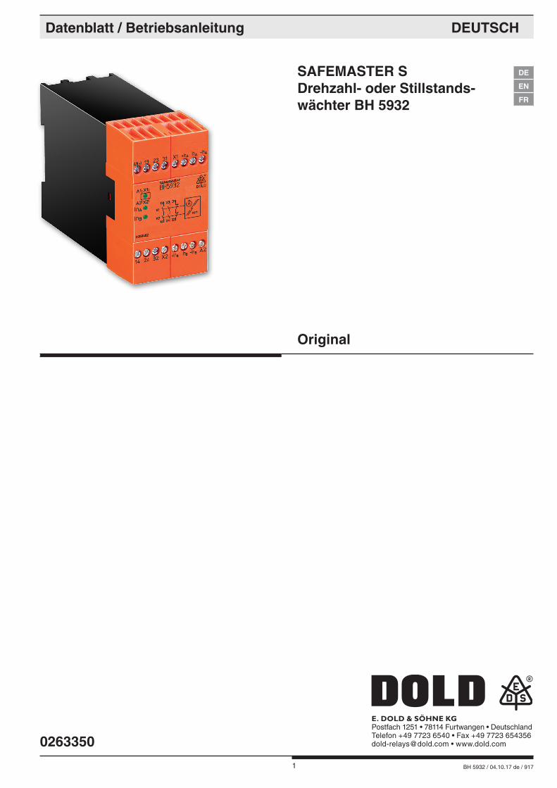
SAFEMASTER S Drehzahl- oder Stillstands- wächter BH 5932
0263350
Datenblatt / Betriebsanleitung DEUTSCH
E. DOLD & SÖHNE KGPostfach 1251 • 78114 Furtwangen • DeutschlandTelefon +49 7723 6540 • Fax +49 7723 [email protected] • www.dold.com
Original
DE
EN
FR
2 BH 5932 / 04.10.17 de / 917
Inhaltsverzeichnis
Symbol- und Hinweiserklärung ..........................................................................................................................................3
Allgemeine Hinweise ........................................................................................................................................................3
Bestimmungsgemäße Verwendung ...................................................................................................................................3
Sicherheitshinweise ...........................................................................................................................................................3
Funktionsdiagramm ...........................................................................................................................................................5
Blockschaltbild ...................................................................................................................................................................5
Zulassungen und Kennzeichen .........................................................................................................................................5
Anwendungen ....................................................................................................................................................................5
Geräteanzeigen .................................................................................................................................................................5
Schaltbild ...........................................................................................................................................................................5
Geräteprogrammierung .....................................................................................................................................................6
Hinweise ............................................................................................................................................................................6
Hinweise ............................................................................................................................................................................7
Technische Daten ..............................................................................................................................................................7
UL-Daten ...........................................................................................................................................................................8
Standardtypen ...................................................................................................................................................................8
Bestellbeispiel für Varianten ..............................................................................................................................................8
Anschlussbeispiel ..............................................................................................................................................................8
Anschlussbeispiele ............................................................................................................................................................9
Anwendungsbeispiel ..........................................................................................................................................................9
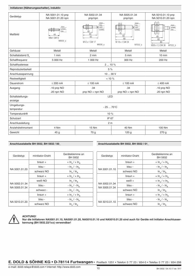
Initiatoren (Näherungsschalter), induktiv .........................................................................................................................10
Anschlusstabelle BH 5932, BH 5932 / 00_ ......................................................................................................................10
Anschlusstabelle BH 5932, BH 5932 / 01_ ......................................................................................................................10
Unit Programming ............................................................................................................................................................16
Beschriftung und Anschlüsse ..........................................................................................................................................31
Maßbild (Maße in mm) ....................................................................................................................................................31
Montage / Demontage der Klemmenblöcke ....................................................................................................................31
Sicherheitstechnische Kenndaten ...................................................................................................................................32
EG-Konformitätserklärung ...............................................................................................................................................33
Notizen ............................................................................................................................................................................34
Notizen ............................................................................................................................................................................35
3 BH 5932 / 04.10.17 de / 917
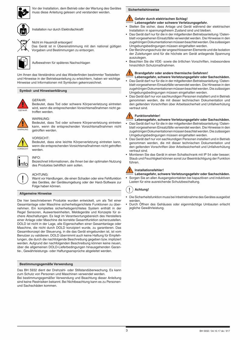
Sicherheitshinweise
WARNUNG
Gefahr durch elektrischen Schlag! Lebensgefahr oder schwere Verletzungsgefahr.• Stellen Sie sicher, dass Anlage und Gerät während der elektrischen Installation in spannungsfreiem Zustand sind und bleiben.• Das Gerät darf nur für die in der mitgeltenden Betriebsanleitung / Daten-
blatt vorgesehenen Einsatzfälle verwendet werden. Die Hinweise in den zugehörigen Dokumentationen müssen beachtet werden. Die zulässigen Umgebungsbedingungen müssen eingehalten werden.
• Der Berührungsschutz der angeschlossenen Elemente und die Isolation der Zuleitungen sind für die höchste am Gerät anliegende Spannung auszulegen.
• Beachten Sie die VDE- sowie die örtlichen Vorschriften, insbesondere hinsichtlich Schutzmaßnahmen.
WARNUNG
Brandgefahr oder andere thermische Gefahren! Lebensgefahr, schwere Verletzungsgefahr oder Sachschäden.• Das Gerät darf nur für die in der mitgeltenden Betriebsanleitung / Daten-
blatt vorgesehenen Einsatzfälle verwendet werden. Die Hinweise in den zugehörigen Dokumentationen müssen beachtet werden. Die zulässigen Umgebungsbedingungen müssen eingehalten werden.
• Das Gerät darf nur von sachkundigen Personen installiert und in Betrieb genommen werden, die mit dieser technischen Dokumentation und den geltenden Vorschriften über Arbeitssicherheit und Unfallverhütung vertraut sind.
WARNUNG
Funktionsfehler! Lebensgefahr, schwere Verletzungsgefahr oder Sachschäden.• Das Gerät darf nur für die in der mitgeltenden Betriebsanleitung / Daten-
blatt vorgesehenen Einsatzfälle verwendet werden. Die Hinweise in den zugehörigen Dokumentationen müssen beachtet werden. Die zulässigen Umgebungsbedingungen müssen eingehalten werden.
• Das Gerät darf nur von sachkundigen Personen installiert und in Betrieb genommen werden, die mit dieser technischen Dokumentation und den geltenden Vorschriften über Arbeitssicherheit und Unfallverhütung vertraut sind.
• Montieren Sie das Gerät in einen Schaltschrank mit IP 54 oder besser; Staub und Feuchtigkeit können sonst zur Beeinträchtigung der Funktion führen.
WARNUNG
Installationsfehler! Lebensgefahr, schwere Verletzungsgefahr oder Sachschäden. • Sorgen Sie an allen Ausgangskontakten bei kapazitiven und induktiven
Lasten für eine ausreichende Schutzbeschaltung.
! Achtung! • Die Sicherheitsfunktion muss bei Inbetriebnahme des Gerätes ausgelöst werden.• Durch Öffnen des Gehäuses oder eigenmächtige Umbauten erlischt jegliche Gewährleistung.
GEFAHR
GEFAHR: Bedeutet, dass Tod oder schwere Körperverletzung eintreten
wird, wenn die entsprechenden Vorsichtsmaßnahmen nicht ge-troffen werden.
WARNUNG
WARNUNG: Bedeutet, dass Tod oder schwere Körperverletzung eintreten
kann, wenn die entsprechenden Vorsichtsmaßnahmen nicht getroffen werden.
VORSICHT
VORSICHT: Bedeutet, dass eine leichte Körperverletzung eintreten kann,
wenn die entsprechenden Vorsichtsmaßnahmen nicht getroffen werden.
! ACHTUNG:
Warnt vor Handlungen, die einen Schaden oder eine Fehlfunktion des Gerätes, der Geräteumgebung oder der Hard-/Software zur Folge haben können.
nfo INFO:
Bezeichnet Informationen, die Ihnen bei der optimalen Nutzung des Produktes behilflich sein sollen.
Die hier beschriebenen Produkte wurden entwickelt, um als Teil einer Gesamtanlage oder Maschine sicherheitsgerichtete Funktionen zu über-nehmen. Ein komplettes sicherheitsgerichtetes System enthält in der Regel Sensoren, Auswerteeinheiten, Meldegeräte und Konzepte für si-chere Abschaltungen. Es liegt im Verantwortungsbereich des Herstellers einer Anlage oder Maschine die korrekte Gesamtfunktion sicherzustellen. DOLD ist nicht in der Lage, alle Eigenschaften einer Gesamtanlage oder Maschine, die nicht durch DOLD konzipiert wurde, zu garantieren. Das Gesamtkonzept der Steuerung, in die das Gerät eingebunden ist, ist vom Benutzer zu validieren. DOLD übernimmt auch keine Haftung für Empfeh-lungen, die durch die nachfolgende Beschreibung gegeben bzw. impliziert werden. Aufgrund der nachfolgenden Beschreibung können keine neuen, über die allgemeinen DOLD-Lieferbedingungen hinausgehenden Garan-tie-, Gewährleistungs- oder Haftungsansprüche abgeleitet werden.
Allgemeine Hinweise
Symbol- und Hinweiserklärung
Bestimmungsgemäße Verwendung
Das BH 5932 dient der Drehzahl- oder Stillstandüberwachung. Es kann zum Schutz von Personen und Maschinen verwendet werden.Bei bestimmungsgemäßer Verwendung und Beachtung dieser Anleitung sind keine Restrisiken bekannt. Bei Nichtbeachtung kann es zu Personen- und Sachschäden kommen.
Installation nur durch Elektrofachkraft!
Nicht im Hausmüll entsorgen! Das Gerät ist in Übereinstimmung mit den national gültigen Vorgaben und Bestimmungen zu entsorgen.
Aufbewahren für späteres Nachschlagen
Um Ihnen das Verständnis und das Wiederfinden bestimmter Textstellen und Hinweise in der Betriebsanleitung zu erleichtern, haben wir wichtige Hinweise und Informationen mit Symbolen gekennzeichnet.
Vor der Installation, dem Betrieb oder der Wartung des Gerätes muss diese Anleitung gelesen und verstanden werden.

4 BH 5932 / 04.10.17 de / 917

5 BH 5932 / 04.10.17 de / 917
• entspricht - Performance Level (PL) e und Kategorie 3 nach EN ISO 13849-1 - SIL-Anspruchsgrenze (SIL CL) 3 nach IEC/EN 62061 - Safety Integrity Level (SIL) 3 nach IEC/EN 61508 und IEC/EN 61511
• für Stop-Kategorie 0 nach EN 418• 2-kanaliger Aufbau• für Überwachungen von Dreh- und Längsbewegungen geeignet• Eingänge für pnp-Näherungsschalter• wahlweise Eingänge für npn-Näherungsschalter• Näherungsschalter-Anschlussüberwachung• fester Ansprechwert• wahlweise einstellbarer Ansprechwert• Rückführkreis X1 - X2 für die Überwachung externer Kontakte• zwangsgeführte Kontakte• 2 Schließer, 1 Öffner• Leiteranschluss: auch 2 x 1,5 mm2 Litze mit Hülse und Kunststoffkragen DIN 46 228-1/-2/-3/-4 oder 2 x 2,5 mm2 Litze mit Hülse DIN 46 228-1/-2/-3• 45 mm Baubreite
0222
807
Für Einrichtbetrieb, Drehzahl- oder Stillstandüberwachung
Stillstandswächter-Betrieb1. grüne LED: leuchtet bei anliegender Hilfsspannung2. grüne LED: leuchtet bei Motorstillstand (Kanal 1)3. grüne LED: leuchtet bei Motorstillstand (Kanal 2)
Überdrehzahl-Überwachung1. grüne LED: leuchtet bei anliegender Hilfsspannung2. grüne LED: leuchtet, wenn keine Überdrehzahl vorliegt (Kanal 1)3. grüne LED: leuchtet, wenn keine Überdrehzahl vorliegt (Kanal 2)
t +tvsRes
tRes : Reset-Zeit nach Anlegen der Versorgungsspannung
tvs : Einschaltverzögerungszeit nach Stillstandserkennung
taus : Ausschaltverzögerungszeit nach Überdrehzahlerkennung
tvs taus
13-1423-24
Stop
Stop
Stop
Mot
orau
s
Mot
orSt
illst
and
Mot
orSt
illst
and
Mot
orSt
illst
and
Mot
orEi
n
Span
nung
Ein
Anwendung Stillstandserkennung AnwendungÜberdrehzahlerkennung
Mot
orEi
n
Mot
orEi
n
Mot
orEi
n
Mot
orEi
n
Über
dreh
zahl
IN A
UH
A1/A2
IN B
IN A : Näherungsschalter A
IN B : Näherungsschalter B
Motor-drehzahl
M6690_e
M7711_a
A1
A2
INA+INA-INA
-INB+INB INB
K1
K2
K1
K2
32
K1
K2
3113 23
14 24
X1 X2
Netzt
eilm
itÜb
ersp
annu
ngs-
und
Kurz
schl
ußsc
hutz
Über
wach
ungs
logi
kAuswertung A
Auswertung B
A1 13 23 31 X1 +INA
+INB
INA -INA
INA
INB -INB
INB
14 24 32 X2 A2M7401_d
K1
K2
13 23 31
14 24 32
A1 X1
A2 X2
Canada / USA A025518
Sicherheitstechnik
SAFEMASTER SDrehzahl- oder StillstandswächterBH 5932
Funktionsdiagramm
Blockschaltbild Schaltbild
Geräteanzeigen
Anwendungen
Zulassungen und Kennzeichen
Alle Angaben in dieser Liste entsprechen dem technischen Stand zum Zeitpunkt der Ausgabe. Technische Verbesserungen und Änderungen behalten wir uns jederzeit vor.
6 BH 5932 / 04.10.17 de / 917
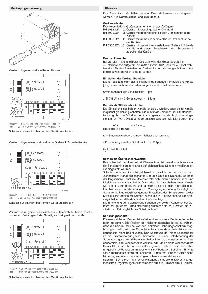
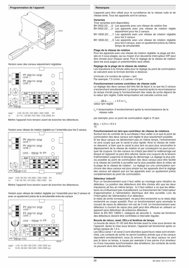
Schalter nur am nicht bestromten Gerät umschalten.
Platte
M23
47_a
Schalter nur am nicht bestromten Gerät umschalten.
Version mit getrennt einstellbaren Kanälen
Version mit gemeinsam einstellbarer Drehzahl für beide Kanäle
Version mit mit gemeinsam einstellbarer Drehzahl für beide Kanäleund einem Feinabgleich der Schaltgleichzeitigkeit der Kanäle
Schalter nur am nicht bestromten Gerät umschalten
Das Gerät kann für Stillstand- oder Drehzahlüberwachung eingesetzt werden. Alle Geräte sind 2-kanalig aufgebaut.
GerätevariantenDrei verschiedene Gerätevarianten stehen zur Verfügung:BH 5932.22/_ _0: Geräte mit fest eingestellter DrehzahlBH 5932.22/_ _2: Geräte mit getrennt einstellbarer Drehzahl für beide KanäleBH 5932.22/_ _1: Geräte mit gemeinsam einstellbarer Drehzahl für bei- de KanäleBH 5932.22/_ _3: Geräte mit gemeinsam einstellbarer Drehzahl für beide Kanäle und einem Feinabgleich der Schaltgleich- zeitigkeit der Kanäle
DrehzahlbereicheBei Geräten mit einstellbarer Drehzahl wird der Gesamtbereich in 4 Unterbereiche aufgeteilt, die mittels zweier DIP-Schalter je Kanal wähl-bar sind. Für das Einstellen der Drehzahl innerhalb des gewählten Unter-bereichs werden Potentiometer benutzt.
Einstellen der DrehzahlbereicheDie für das Einstellen des Schaltpunktes benötigten Impulse pro Minute [lpm] lassen sich mit der unten aufgeführten Formel berechnen:
U/min x Anzahl der Schaltnocken = Ipm
z. B. 7,5 U/min x 2 Schaltnocken = 15 Ipm
Betrieb als StillstandswächterDie Einstellung der beiden Kanäle ist so zu wählen, dass beide Kanäle möglichst gleichzeitig schalten. Die maximale Zeit nach der Stillstandser-kennung bis zum Schalten der Ausgangsrelais ist abhängig vom einge-stellten Ipm-Wert. Diese Verzögerungszeit lässt sich wie folgt berechnen:
60 s + 2,5 s = tvs
eingestellter Ipm-Wert tvs Einschaltverzögerung nach Stillstandserkennung
z.B. beim eingestellten Schaltpunkt von 15 Ipm
60 s + 2,5 s = 6,5 s15
Betrieb als ÜberdrehzahlwächterBesonders bei der Überdrehzahlüberwachung ist darauf zu achten, dass die Schaltpunkte beider Kanäle auf gleichzeitiges Schalten möglichst ex-akt eingestellt werden.Schalten beide Kanäle nicht gleichzeitig ab, wird der Antrieb nur von dem „schnelleren“ Kanal abgeschaltet. Dadurch sinkt die Drehzahl, so dass der langsamere Kanal die Überdrehzahl nicht mehr erkennen kann und folglich auch nicht abschaltet. Durch das Nichtabschalten eines Kanals wird der Neustart blockiert, und das Gerät lässt sich nicht mehr einschal-ten. Nur eine Unterbrechung der Versorgungsspannung beseitigt die Startsperre. Eine möglichst genaue Einstellung der Schaltpunkte beider Kanäle kann erleichtert werden, wenn die zu überwachende Drehzahl möglichst in der Mitte des Drehzahlbereichs liegt.Die Einstellung auf gleichzeitiges Schalten der beiden Kanäle ist bei Ge-räten mit getrennter Kanaleinstellung einfacher als bei Geräten mit zu-sätzlichem Feinabgleich des Schaltpunktes.
NäherungsschalterFür einen sicheren Betrieb ist auf eine vibrationsfreie Montage der Initia-toren zu achten. Die Position der Näherungsschalter ist so zu wählen, dass die beiden Impulse von den einzelnen Näherungsschaltern mög-lichst gleichzeitig erfolgen. Dabei ist zu beachten, dass die Initiatoren sich gegenseitig nicht beeinflussen. Der Anschluss der Näherungsschalter an die Stromversorgung wird überwacht. Bei einer Unterbrechung der Stromversorgung am Näherungsschalter kann das entsprechende Aus-gangsrelais nicht eingeschaltet werden, oder das bereits eingeschaltete Relais fällt sofort ab. Für einen störungsfreien Betrieb muss der Nähe-rungsschalter-Ruhestrom mindestens 3 mA betragen. Bei einem Einsatz von Näherungsschaltern mit kleinerem Ruhestrom können Geräte ohne Näherungsschalter-Überwachungsanschluss verwendet werden.Nach EN ISO 13849-1, Sicherheitskategorie 3 sind die Initiatoren in ange-messenen, regelmäßigen Zeitabständen auf ihre Funktionalität zu prüfen.
*
Bereich* : 8-60 / 60-450 / 450-3600 / 1800-14000oder 20-110 / 120-900 / 950-7000 / 3700-26000
M7821_b
xx-xx xx-xx xx-xx xx-xx
IpmIpm
*
Bereich* : 5-40 / 35-340 / 300-2700 / 1200-10500oder 10-80 / 80-650 / 600-5300 / 2400-20000
xx-xx xx-xx xx-xx xx-xx
M9406
IpmIpm
*
Bereich* : 8-60 / 60-450 / 450-3600 / 1800-14000
oder 7-90 / 60-700 / 470-5500 / 1800-21000
xx-xx xx-xx xx-xx xx-xx
M10948
IpmIpm
Geräteprogrammierung Hinweise
7 BH 5932 / 04.10.17 de / 917
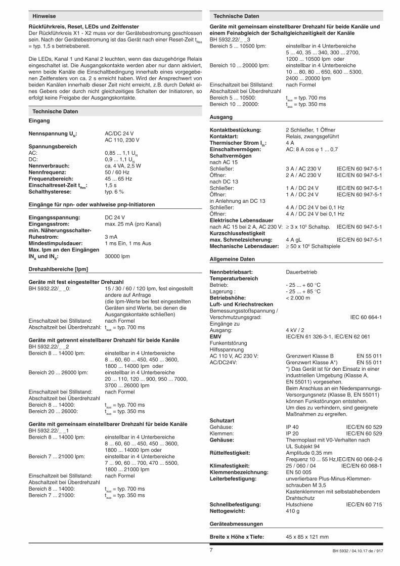
Geräte mit gemeinsam einstellbarer Drehzahl für beide Kanäle und einem Feinabgleich der Schaltgleichzeitigkeit der KanäleBH 5932.22/_ _3Bereich 5 ... 10500 lpm: einstellbar in 4 Unterbereiche 5 ... 40, 35 ... 340, 300 ... 2700, 1200 ... 10500 Ipm oderBereich 10 ... 20000 lpm: einstellbar in 4 Unterbereiche 10 ... 80, 80 ... 650, 600 ... 5300, 2400 ... 20000 IpmEinschaltzeit bei Stillstand: nach FormelAbschaltzeit bei Überdrehzahl Bereich 5 ... 10500: taus = typ. 700 msBereich 10 ... 20000: taus = typ. 350 ms
Ausgang
Kontaktbestückung: 2 Schließer, 1 ÖffnerKontaktart: Relais, zwangsgeführtThermischer Strom Ith: 4 AEinschaltvermögen: AC: 8 A cos ϕ 1 ... 0,7Schaltvermögennach AC 15Schließer: 3 A / AC 230 V IEC/EN 60 947-5-1Öffner: 2 A / AC 230 V IEC/EN 60 947-5-1nach DC 13Schließer: 1 A / DC 24 V IEC/EN 60 947-5-1Öffner: 1 A / DC 24 V IEC/EN 60 947-5-1in Anlehnung an DC 13Schließer: 4 A / DC 24 V bei 0,1 Hz Öffner: 4 A / DC 24 V bei 0,1 Hz Elektrische Lebensdauer nach AC 15 bei 2 A, AC 230 V: ≥ 3 x 10⁵ Schaltsp. IEC/EN 60 947-5-1Kurzschlussfestigkeitmax. Schmelzsicherung: 4 A gL IEC/EN 60 947-5-1Mechanische Lebensdauer: ≥ 50 x 106 Schaltspiele
Allgemeine Daten
Nennbetriebsart: DauerbetriebTemperaturbereichBetrieb: - 25 ... + 60 °CLagerung : - 25 ... + 85 °CBetriebshöhe: < 2.000 mLuft- und KriechstreckenBemessungsstoßspannung /Verschmutzungsgrad: IEC 60 664-1Eingänge zuAusgang: 4 kV / 2EMV IEC/EN 61 326-3-1, IEC/EN 62 061FunkentstörungHilfsspannung AC 110 V, AC 230 V: Grenzwert Klasse B EN 55 011AC/DC24V: Grenzwert Klasse A*) EN 55 011 *) Das Gerät ist für den Einsatz in einer industriellen Umgebung (Klasse A, EN 55011) vorgesehen. Beim Anschluss an ein Niederspannungs- Versorgungsnetz (Klasse B, EN 55011) können Funkstörungen entstehen. Um dies zu verhindern, sind geeignete Maßnahmen zu ergreifen.SchutzartGehäuse: IP 40 IEC/EN 60 529Klemmen: IP 20 IEC/EN 60 529Gehäuse: Thermoplast mit V0-Verhalten nach UL Subjekt 94Rüttelfestigkeit: Amplitude 0,35 mm Frequenz 10 ... 55 Hz, IEC/EN 60 068-2-6Klimafestigkeit: 25 / 060 / 04 IEC/EN 60 068-1Klemmenbezeichnung: EN 50 005Leiterbefestigung: unverlierbare Plus-Minus-Klemmen- schrauben M 3,5 Kastenklemmen mit selbstabhebendem DrahtschutzSchnellbefestigung: Hutschiene IEC/EN 60 715Nettogewicht: 410 g
Geräteabmessungen
Breite x Höhe x Tiefe: 45 x 85 x 121 mm
Eingang
Nennspannung UN: AC/DC 24 V AC 110, 230 VSpannungsbereichAC: 0,85 ... 1,1 UN
DC: 0,9 ... 1,1 UN
Nennverbrauch: ca. 4 VA, 2,5 WNennfrequenz: 50 / 60 HzFrequenzbereich: 45 ... 65 HzEinschaltreset-Zeit tRes: 1,5 sSchalthysterese: typ. 6 %
Eingänge für npn- oder wahlweise pnp-Initiatoren
Eingangsspannung: DC 24 VEingangsstrom: max. 25 mA (pro Kanal)min. Näherungsschalter-Ruhestrom: 3 mAMindestimpulsdauer: 1 ms Ein, 1 ms AusMax. lpm an den EingängenINA und INB: 30000 lpm
Drehzahlbereiche [lpm]
Geräte mit fest eingestellter DrehzahlBH 5932.22/_ _0: 15 / 30 / 60 / 120 Ipm, fest eingestellt andere auf Anfrage (die Ipm-Werte bei fest eingestellten Geräten sind Werte, bei denen die Ausgangskontakte schließen)Einschaltzeit bei Stillstand: nach FormelAbschaltzeit bei Überdrehzahl: taus = typ. 700 ms
Geräte mit getrennt einstellbarer Drehzahl für beide KanäleBH 5932.22/_ _2Bereich 8 ... 14000 lpm: einstellbar in 4 Unterbereiche 8 ... 60, 60 ... 450, 450 ... 3600, 1800 ... 14000 Ipm oderBereich 20 ... 26000 lpm: einstellbar in 4 Unterbereiche 20 ... 110, 120 ... 900, 950 ... 7000, 3700 ... 26000 IpmEinschaltzeit bei Stillstand: nach FormelAbschaltzeit bei Überdrehzahl Bereich 8 ... 14000: taus = typ. 700 msBereich 20 ... 26000: taus = typ. 350 ms
Geräte mit gemeinsam einstellbarer Drehzahl für beide KanäleBH 5932.22/_ _1Bereich 8 ... 14000 lpm: einstellbar in 4 Unterbereiche 8 ... 60, 60 ... 450, 450 ... 3600, 1800 ... 14000 Ipm oderBereich 7 ... 21000 lpm: einstellbar in 4 Unterbereiche 7 ... 90, 60 ... 700, 470 ... 5500, 1800 ... 21000 IpmEinschaltzeit bei Stillstand: nach FormelAbschaltzeit bei ÜberdrehzahlBereich 8 ... 14000: taus = typ. 700 msBereich 7 ... 21000: taus = typ. 350 ms
Rückführkreis, Reset, LEDs und ZeitfensterDer Rückführkreis X1 - X2 muss vor der Gerätebestromung geschlossen sein. Nach der Gerätebestromung ist das Gerät nach einer Reset-Zeit tRes = typ. 1,5 s betriebsbereit.
Die LEDs, Kanal 1 und Kanal 2 leuchten, wenn das dazugehörige Relais eingeschaltet ist. Die Ausgangskontakte werden aber nur dann aktiviert, wenn beide Kanäle die Einschaltbedingung innerhalb eines vorgegebe-nen Zeitfensters von ca. 2 s erreicht haben. Wird der Ansprechwert von beiden Kanälen innerhalb dieser Zeit nicht erreicht, z.B. durch Defekt ei-nes Gebers oder durch nicht gleichzeitiges Schalten der Initiatoren, so erfolgt keine Freigabe der Ausgangskontakte.
Hinweise Technische Daten
Technische Daten
8 BH 5932 / 04.10.17 de / 917
A2
INA INB
-INA -INB
+INA +INB
M6688_b
A1 X1 X2 13
14N(-)
L1(+)
31
32
23
24
BH5932
Nähe
rung
ssch
alte
r1
Nähe
rung
ssch
alte
r2
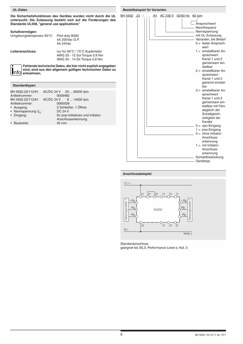
Standardanschlussgeeignet bis SIL3, Performance Level e, Kat. 3
BH 5932.22/112/61 AC/DC 24 V 20 ... 26000 IpmArtikelnummer: 0059482BH 5932.22/112/61 AC/DC 24 V 8 ... 14000 IpmArtikelnummer: 0065009• Ausgang: 2 Schließer, 1 Öffner• Nennspannung UN: DC 24 V• Eingang: für pnp-Initiatoren und Initiator- Anschlusserkennung• Baubreite: 45 mm
Die Sicherheitsfunktionen des Gerätes wurden nicht durch die UL untersucht. Die Zulassung bezieht sich auf die Forderungen des Standards UL508, “general use applications“
Schaltvermögen:Umgebungstemperatur 60°C: Pilot duty B300 4A 250Vac G.P. 4A 24Vdc
Leiteranschluss: nur für 60°C / 75°C Kupferleiter AWG 20 - 12 Sol Torque 0.8 Nm AWG 20 - 14 Str Torque 0.8 Nm
nfoFehlende technische Daten, die hier nicht explizit angegeben sind, sind aus den allgemein gültigen technischen Daten zu entnehmen.
BH 5932 .22 /_ _ _ /61 AC 230 V 50/60 Hz 60 Ipm Ansprechwert Nennfrequenz Nennspannung mit UL-Zulassung Varianten, bei Bedarf 0 = fester Ansprech- wert 1 = einstellbarer An- sprechwert Kanal 1 und 2 gemeinsam ein- stellbar 2 = einstellbarer An- sprechwert Kanal 1 und 2 getrennt einstell- bar 3 = einstellbarer An- sprechwert Kanal 1 und 2 gemeinsam ein- stellbar mit Fein- abgleich der Schalt gleich- zeitigkeit der Kanäle 0 = npn-Eingang 1 = pnp-Eingang 0 = ohne Initiator- Anschluss- erken nung 1 = mit Initiator- Anschluss- erken nung Kontaktbestückung Gerätetyp
Bestellbeispiel für VariantenUL-Daten
Standardtypen
Anschlussbeispiel
9 BH 5932 / 04.10.17 de / 917
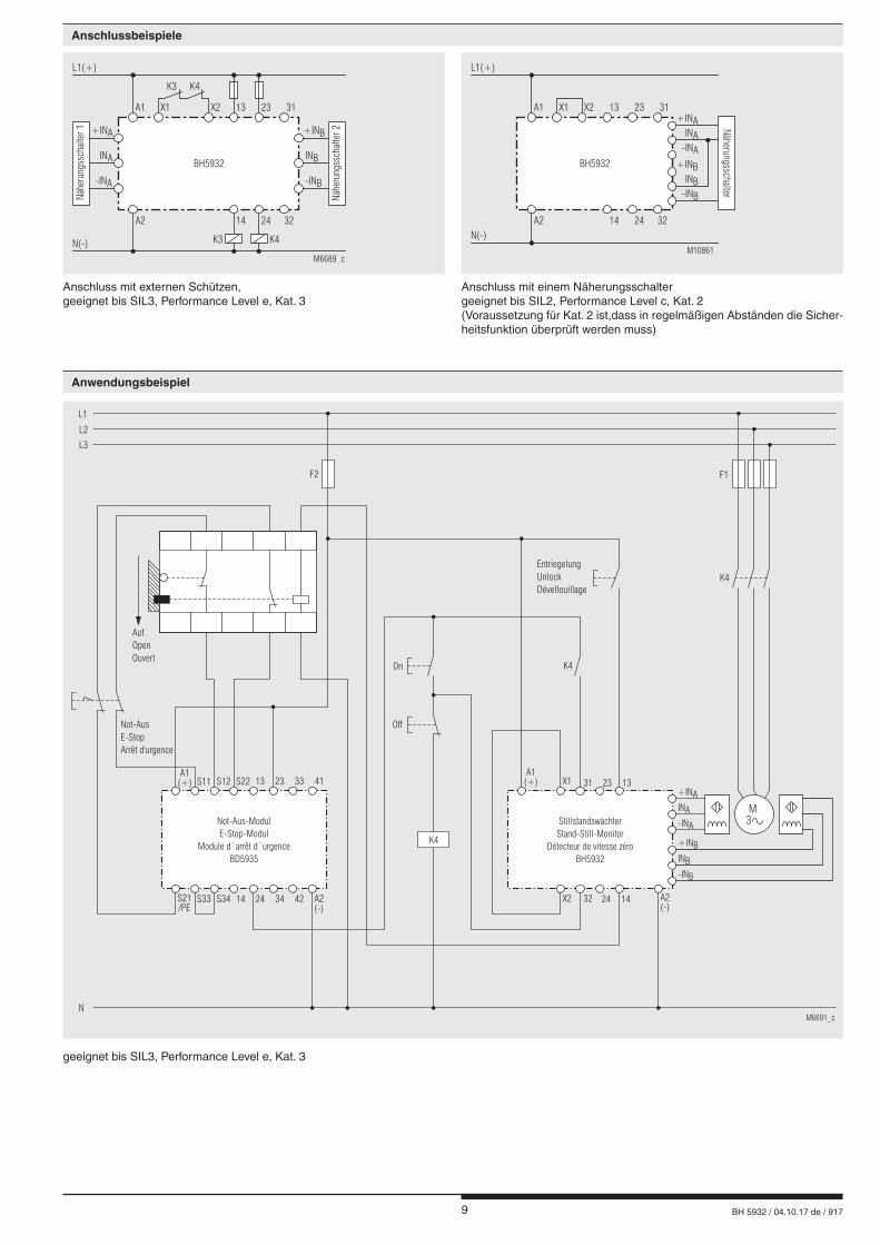
Anschluss mit externen Schützen, geeignet bis SIL3, Performance Level e, Kat. 3
A1(+)
On K4
K4
F2
S11 S12 S22 13 23 33 41
S21/PE
S33 S34 14 24 34 42 A2(-)
EntriegelungUnlockDévellouillage
F1
Off
StillstandswächterStand-Still-Monitor
Détecteur de vitesse zéroBH5932
Not-AusE-StopArrêt d'urgence
AufOpenOuvert
L1
L2
L3
N
Not-Aus-ModulE-Stop-Modul
Module d`arrêt d`urgenceBD5935
M6691_c
A1(+) X1
X2
31
32
13
14 A2(-)
23
24
K4
INA
+INA
-INA
INB
+INB
-INB
M3
A2
INA INB
-INA -INB
+INA +INB
M6689_c
A1 X1 X2 13
14
N(-)
L1(+)
31
32
K3
K3 K4
K4
23
24
BH5932
Näh
erungss
chal
ter
1
Näh
erungss
chal
ter
2
A2
INB
INA
-INB
-INA
+INB
+INA
M10861
A1 X1 X2 13
14
N(-)
L1(+)
31
32
23
24
BH5932
Näh
erungssc
halter
Anschluss mit einem Näherungsschaltergeeignet bis SIL2, Performance Level c, Kat. 2 (Voraussetzung für Kat. 2 ist,dass in regelmäßigen Abständen die Sicher-heitsfunktion überprüft werden muss)
geeignet bis SIL3, Performance Level e, Kat. 3
Anschlussbeispiele
Anwendungsbeispiel
10 BH 5932 / 04.10.17 de / 917
GerätetypNA 5001.01.10 pnpNA 5001.01.20 npn
NA 5002.01.34pnp/npn
NA 5005.01.34pnp/npn
NA 5010.01.10 pnpNA 5010.01.20 npn
Maßbild
M6935_a
44
M8x1 SW13
braunschwarzblau 49
6065
M12 x 1 SW 17M6936_a
braunblau
schwarzweiß
M7032_a
456068
M 18 x 1 SW 24
braunblau
schwarzweiß
M7033_b
4960
80
M30 x 1,5 SW 36
braun
blauschwarz
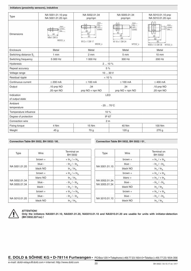
Gehäuse Metall Metall Metall Metall
Schaltabstand Sn 1 mm 2 mm 5 mm 10 mm
Schaltfrequenz 5 000 Hz 1 000 Hz 300 Hz 200 Hz
Schalthysterese 2 ... 10 %
Reproduzierbarkeit 5 %
Anschlussspannung 10 ... 30 V
Restwelligkeit < 10 %
Dauerstrom ≤ 200 mA ≤ 100 mA ≤ 100 mA ≤ 400 mA
Ausgang .10 pnp NO
.20 npn NO
.34
pnp NO + npn NO
.34
pnp NO + npn NO
.10 pnp NO
.20 npn NO
Schaltstellungs-
anzeige
LED
Umgebungs-
temperatur- 25 ... 70°C
Temperaturdrift 10 %
Schutzart IP 67
Anschlussleitung 2 m
Anziehdrehmoment 4 Nm 15 Nm 40 Nm 100 Nm
Gewicht 45 g 70 g 120 g 270 g
Anschlusstabelle BH 5932, BH 5932 / 00_
Gerätetyp minitiator-DrahtGeräteklemme an
BH 5932
NA 5001.01.20
braun + + InA / + InB
blau - - InA / - InB
schwarz NO InA / InB
NA 5002.01.34
NA 5005.01.34
braun + + InA / + InB
weiß NO InA / InB
blau - - InA / - InB
schwarz - - InA / - InB
NA 5010.01.20
braun + + InA / + InB
blau - - InA / - InB
schwarz NO InA / InB
Anschlusstabelle BH 5932, BH 5932 / 01_
Gerätetyp minitiator-DrahtGeräteklemme an
BH 5932
NA 5001.01.10
braun + + InA / + InB
blau - - InA / - InB
schwarz NO InA / InB
NA 5002.01.34
NA 5005.01.34
braun + + InA / + InB
weiß + + InA / + InB
blau - - InA / - InB
schwarz NO InA / InB
NA 5010.01.10
braun + + InA / + InB
blau - - InA / - InB
schwarz NO InA / InB
ACHTUNG! Nur die Initiatoren NA5001.01.10, NA5001.01.20, NA5010.01.10 und NA5010.01.20 sind auch für Geräte mit Initiator-Anschlusser-
kennung (BH 5932.22/1xx) verwendbar!
Initiatoren (Näherungsschalter), induktiv
E. DOLD & SÖHNE KG • D-78114 Furtwangene-mail: [email protected] • internet: http://www.dold.com
• Postfach 1251 • Telefon 0 77 23 / 654-0 • Telefax 0 77 23 / 654-356
11 BH 5932 / 04.10.17 en / 917
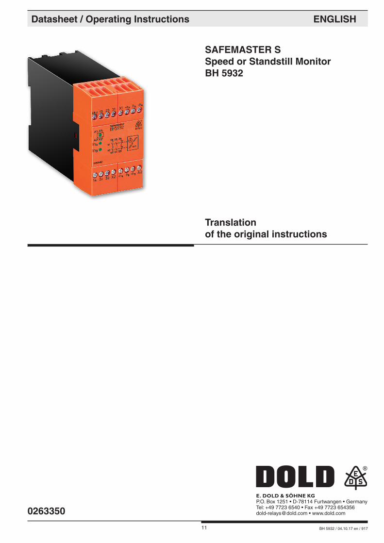
SAFEMASTER S Speed or Standstill Monitor BH 5932
Datasheet / Operating Instructions ENGLISH
E. DOLD & SÖHNE KGP.O. Box 1251 • D-78114 Furtwangen • GermanyTel: +49 7723 6540 • Fax +49 7723 [email protected] • www.dold.com
Translation of the original instructions
0263350
12 BH 5932 / 04.10.17 en / 917
Contents
Symbol and Notes Statement ..........................................................................................................................................13
General Notes .................................................................................................................................................................13
Designated Use ...............................................................................................................................................................13
Safety Notes ....................................................................................................................................................................13
Function Diagram ............................................................................................................................................................15
Block Diagram .................................................................................................................................................................15
Approvals and Markings ..................................................................................................................................................15
Application .......................................................................................................................................................................15
Indication .........................................................................................................................................................................15
Circuit Diagram ................................................................................................................................................................15
Notes ...............................................................................................................................................................................16
Technical Data .................................................................................................................................................................17
UL-Data ...........................................................................................................................................................................18
Standard Type ..................................................................................................................................................................18
Ordering example for variants .........................................................................................................................................18
Connection Example .......................................................................................................................................................18
Connection Examples ......................................................................................................................................................19
Application Example ........................................................................................................................................................19
Initiators (proximity sensors), induktive ............................................................................................................................20
Connection Table BH 5932, BH 5932 / 00_ .....................................................................................................................20
Connection Table BH 5932, BH 5932 / 01_ .....................................................................................................................20
Labeling and connections ................................................................................................................................................31
Dimensions (dimensions in mm) .....................................................................................................................................31
Mounting / disassembly of the terminal blocks ................................................................................................................31
Safety Related Data ........................................................................................................................................................32
CE-Declaration of Conformity ..........................................................................................................................................33
Notice ..............................................................................................................................................................................34
Notice ..............................................................................................................................................................................35
13 BH 5932 / 04.10.17 en / 917
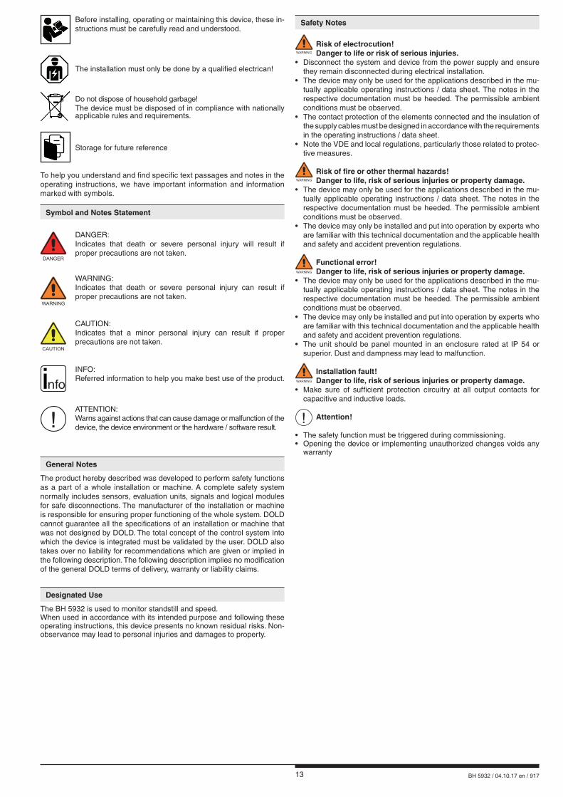
Safety Notes
WARNING
Risk of electrocution! Danger to life or risk of serious injuries. • Disconnect the system and device from the power supply and ensure they remain disconnected during electrical installation.• The device may only be used for the applications described in the mu-
tually applicable operating instructions / data sheet. The notes in the respective documentation must be heeded. The permissible ambient conditions must be observed.
• The contact protection of the elements connected and the insulation of the supply cables must be designed in accordance with the requirements in the operating instructions / data sheet.
• Note the VDE and local regulations, particularly those related to protec-tive measures.
WARNING
Risk of fire or other thermal hazards! Danger to life, risk of serious injuries or property damage. • The device may only be used for the applications described in the mu-
tually applicable operating instructions / data sheet. The notes in the respective documentation must be heeded. The permissible ambient conditions must be observed.
• The device may only be installed and put into operation by experts who are familiar with this technical documentation and the applicable health and safety and accident prevention regulations.
WARNING
Functional error! Danger to life, risk of serious injuries or property damage. • The device may only be used for the applications described in the mu-
tually applicable operating instructions / data sheet. The notes in the respective documentation must be heeded. The permissible ambient conditions must be observed.
• The device may only be installed and put into operation by experts who are familiar with this technical documentation and the applicable health and safety and accident prevention regulations.
• The unit should be panel mounted in an enclosure rated at IP 54 or superior. Dust and dampness may lead to malfunction.
WARNING
Installation fault! Danger to life, risk of serious injuries or property damage. • Make sure of sufficient protection circuitry at all output contacts for
capacitive and inductive loads.
! Attention! • The safety function must be triggered during commissioning.• Opening the device or implementing unauthorized changes voids any warranty
DANGER
DANGER: Indicates that death or severe personal injury will result if
proper precautions are not taken.
WARNING
WARNING: Indicates that death or severe personal injury can result if
proper precautions are not taken.
CAUTION
CAUTION: Indicates that a minor personal injury can result if proper
precautions are not taken.
! ATTENTION:
Warns against actions that can cause damage or malfunction of the device, the device environment or the hardware / software result.
nfo INFO:
Referred information to help you make best use of the product.
Symbol and Notes Statement
The installation must only be done by a qualified electrican!
Do not dispose of household garbage! The device must be disposed of in compliance with nationally
applicable rules and requirements.
To help you understand and find specific text passages and notes in the operating instructions, we have important information and information marked with symbols.
Before installing, operating or maintaining this device, these in-structions must be carefully read and understood.
The product hereby described was developed to perform safety functions as a part of a whole installation or machine. A complete safety system normally includes sensors, evaluation units, signals and logical modules for safe disconnections. The manufacturer of the installation or machine is responsible for ensuring proper functioning of the whole system. DOLD cannot guarantee all the specifications of an installation or machine that was not designed by DOLD. The total concept of the control system into which the device is integrated must be validated by the user. DOLD also takes over no liability for recommendations which are given or implied in the following description. The following description implies no modification of the general DOLD terms of delivery, warranty or liability claims.
General Notes
Designated Use
The BH 5932 is used to monitor standstill and speed.When used in accordance with its intended purpose and following these operating instructions, this device presents no known residual risks. Non-observance may lead to personal injuries and damages to property.
Storage for future reference

14 BH 5932 / 04.10.17 en / 917
15 BH 5932 / 04.10.17 en / 917
Safety technique
SAFEMASTER S Speed or Standstill Monitor BH 5932
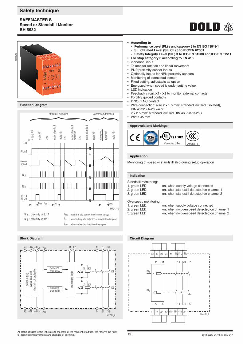
• According to - Performance Level (PL) e and category 3 to EN ISO 13849-1 - SIL Claimed Level (SIL CL) 3 to IEC/EN 62061 - Safety Integrity Level (SIL) 3 to IEC/EN 61508 and IEC/EN 61511
• For stop category 0 according to EN 418• 2-channel input• To monitor rotation and linear movement• PNP proximity sensor inputs• Optionally inputs for NPN proximity sensors• Monitoring of connected sensor• Fixed setting, adjustable as option• Energized when speed is under setting value• LED indication• Feedback circuit X1 - X2 to monitor external contacts• Forcibly guided contacts• 2 NO, 1 NC contact• Wire connection: also 2 x 1.5 mm2 stranded ferruled (isolated), DIN 46 228-1/-2/-3/-4 or 2 x 2.5 mm2 stranded ferruled DIN 46 228-1/-2/-3• Width 45 mm
0223
010
Monitoring of speed or standstill also during setup operation
Standstill monitoring:1. green LED: on, when supply voltage connected2. green LED: on, when standstill detected on channel 13. green LED: on, when standstill detected on channel 2
Overspeed monitoring:1. green LED: on, when supply voltage connected2. green LED: on, when no overspeed detected on channel 13. green LED: on, when no overspeed detected on channel 2
M7712_a
A1
A2
INA+INA-INA
-INB+INB INB
K1
K2
K1
K2
32
K1
K2
3113 23
14 24
X1 X2
powe
rsup
ply
over
volta
gean
dsh
ort c
ircui
t pro
tect
ion
mon
itorin
glo
gic
detectionchannel A
detectionchannel B
A1 13 23 31 X1 +INA
+INB
INA -INA
INA
INB -INB
INB
14 24 32 X2 A2M7401_d
K1
K2
13 23 31
14 24 32
A1 X1
A2 X2
t +tvsRes
tRes : reset time after connection of supply voltage
tvs : operate delay after detection of standstill/underspeed
taus : release delay after detection of overspeed
tvs taus
13-1423-24
stop
stop
stop
mot
orOf
f
mot
orst
ands
till
mot
orst
ands
till
mot
orst
ands
till
mot
orOn
supp
lyOn
standstill detection overspeed detection
mot
orOn
mot
orOn
mot
orOn
mot
orOn
over
spee
d
IN A
UH
A1/A2
IN B
IN A : proximity switch A
IN B : proximity switch B
motor-speed
M7047_c
Canada / USA A025518
Function Diagram
Block Diagram
Approvals and Markings
Application
Indication
Circuit Diagram
All technical data in this list relate to the state at the moment of edition. We reserve the rightfor technical improvements and changes at any time.
16 BH 5932 / 04.10.17 en / 917
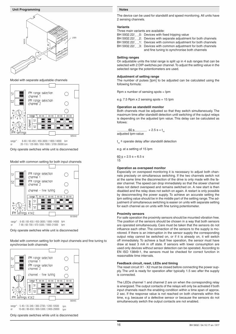
Only operate switches while unit is disconnected
Model with separate adjustable channels
Model with common setting for both input channels and fine tuning to synchronise both channels
The device can be used for standstill and speed monitoring. All units have 2 sensing channels.
VariantsThree main variants are available:BH 5932.22/_ _0: Devices with fixed tripping valueBH 5932.22/_ _2: Devices with separate adjustment for both channelsBH 5932.22/_ _1: Devices with common adjustment for both channelsBH 5932.22/_ _3: Devices with common adjustment for both channels and fine tuning to synchronise both channels
Setting rangesOn adjustable units the total range is split up in 4 sub ranges that can be selected with 2 DIP-switches per channel. To adjust the setting value in the selected range the potentiometers are used.
Adjustment of setting rangeThe number of pulses [lpm] to be adjusted can be calculated using the following formula:
Rpm x number of sensing spots = Ipm
e.g. 7.5 Rpm x 2 sensing spots = 15 Ipm
Operation as standstill monitorBoth channels must be adjusted so that they switch simultaneously. The maximum time after standstill detection until switching of the output relays is depending on the adjusted lpm value. This delay can be calculated as follows:
60 s + 2.5 s = tvs
adjusted Ipm-value tvs operate delay after standstill detection
e.g. at a setting of 15 lpm
60 s + 2.5 s = 6.5 s15
Operation as overspeed monitorEspecially on overspeed monitoring it is necessary to adjust both chan-nels precisely on simultaneous switching. If the two channels switch not at the same time the disconnection of the drive is only made with the fa-ster channel. The speed can drop immediately so that the slower channel does not detect overspeed and remains switched on. A new start is then disabled and the relay does not switch on again. A restart is only possible by desconnecting the power supply. To achieve an accurate setting the lpm setting value should be in the middle part of the setting range. The ad-justment of simultaneous switching is easier on units with separate setting for each channel as on units with fine tuning potentiometer.
Proximity sensorsFor safe operation the proximity sensors should be mounted vibration free. The position of the sensors should be chosen in a way that both sensors are operated simultaneously. Care must be taken that the sensors do not influence each other. The connection of the sensors to the supply is mo-nitored. If there is an interruption in the sensor supply the corresponding output relay cannot be switched on, or if it is already on, it will switch off immediately. To achieve a fault free operation, the sensor must have draw at least 3 mA in off state. If sensors with lower consumption are used only devices without sensor detection can be operated. According to EN ISO 13849-1, the sensors must be checked for correct function in reasonalble time intervals.
Feedback circuit, reset, LEDs and timingThe reset circuit X1 - X2 must be closed before connecting the power sup-ply. The unit is ready for operation after typically 1.5 sec after the supply is connected.
The LEDs channel 1 and channel 2 are on when the corresponding relay is energized. The output contacts of the relays will only be activated if both input channels reach the enabling condition within a time span of approx. 2 sec. If the response value is not reached on both channels within this time, e.g. because of a defective sensor or because the sensors do not simultaneously switch the output contacts are not enabled.
*
range* : 8-60 / 60-450 / 450-3600 / 1800-14000
or 20-110 / 120-900 / 950-7000 / 3700-26000
M9444
xx-xx xx-xx xx-xx xx-xx
IpmIpm
*
range* : 5-40 / 35-340 / 300-2700 / 1200-10500
or 10-80 / 80-650 / 600-5300 / 2400-20000
xx-xx xx-xx xx-xx xx-xx
M9445
IpmIpm
plate
M29
29
Only operate switches while unit is disconnected
Model with common setting for both input channels
Only operate switches while unit is disconnected
*
range* :
or
8-60 / 60-450 / 450-3600 / 1800-14000
7-90 / 60-700 / 470-5500 / 1800-21000
xx-xx xx-xx xx-xx xx-xx
M10949
IpmIpm
Unit Programming Notes
17 BH 5932 / 04.10.17 en / 917
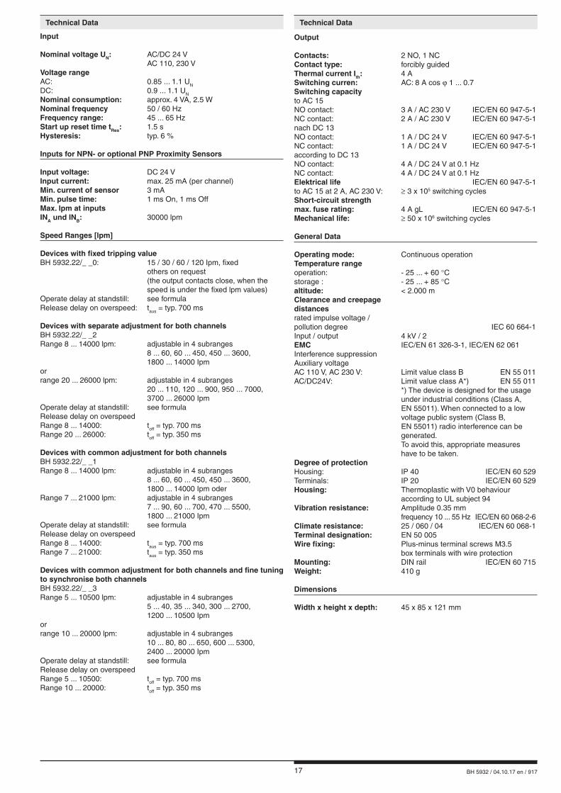
Output
Contacts: 2 NO, 1 NCContact type: forcibly guidedThermal current Ith: 4 ASwitching curren: AC: 8 A cos ϕ 1 ... 0.7Switching capacity to AC 15NO contact: 3 A / AC 230 V IEC/EN 60 947-5-1NC contact: 2 A / AC 230 V IEC/EN 60 947-5-1nach DC 13NO contact: 1 A / DC 24 V IEC/EN 60 947-5-1NC contact: 1 A / DC 24 V IEC/EN 60 947-5-1according to DC 13NO contact: 4 A / DC 24 V at 0.1 Hz NC contact: 4 A / DC 24 V at 0.1 HzElektrical life IEC/EN 60 947-5-1to AC 15 at 2 A, AC 230 V: ≥ 3 x 10⁵ switching cycles Short-circuit strengthmax. fuse rating: 4 A gL IEC/EN 60 947-5-1Mechanical life: ≥ 50 x 106 switching cycles
General Data
Operating mode: Continuous operationTemperature rangeoperation: - 25 ... + 60 °Cstorage : - 25 ... + 85 °Caltitude: < 2.000 mClearance and creepagedistancesrated impulse voltage /pollution degree IEC 60 664-1Input / output 4 kV / 2EMC IEC/EN 61 326-3-1, IEC/EN 62 061Interference suppressionAuxiliary voltage AC 110 V, AC 230 V: Limit value class B EN 55 011AC/DC24V: Limit value class A*) EN 55 011 *) The device is designed for the usage under industrial conditions (Class A, EN 55011). When connected to a low voltage public system (Class B, EN 55011) radio interference can be generated. To avoid this, appropriate measures have to be taken.Degree of protectionHousing: IP 40 IEC/EN 60 529Terminals: IP 20 IEC/EN 60 529Housing: Thermoplastic with V0 behaviour according to UL subject 94Vibration resistance: Amplitude 0.35 mm frequency 10 ... 55 Hz IEC/EN 60 068-2-6Climate resistance: 25 / 060 / 04 IEC/EN 60 068-1Terminal designation: EN 50 005Wire fixing: Plus-minus terminal screws M3.5 box terminals with wire protectionMounting: DIN rail IEC/EN 60 715Weight: 410 g
Dimensions
Width x height x depth: 45 x 85 x 121 mm
Input
Nominal voltage UN: AC/DC 24 V AC 110, 230 VVoltage rangeAC: 0.85 ... 1.1 UN
DC: 0.9 ... 1.1 UN
Nominal consumption: approx. 4 VA, 2.5 WNominal frequency 50 / 60 HzFrequency range: 45 ... 65 HzStart up reset time tRes: 1.5 sHysteresis: typ. 6 %
Inputs for NPN- or optional PNP Proximity Sensors
Input voltage: DC 24 VInput current: max. 25 mA (per channel)Min. current of sensor 3 mAMin. pulse time: 1 ms On, 1 ms OffMax. lpm at inputsINA und INB: 30000 lpm
Speed Ranges [lpm]
Devices with fixed tripping valueBH 5932.22/_ _0: 15 / 30 / 60 / 120 Ipm, fixed others on request (the output contacts close, when the speed is under the fixed lpm values)Operate delay at standstill: see formulaRelease delay on overspeed: taus = typ. 700 ms
Devices with separate adjustment for both channelsBH 5932.22/_ _2Range 8 ... 14000 lpm: adjustable in 4 subranges 8 ... 60, 60 ... 450, 450 ... 3600, 1800 ... 14000 Ipmorrange 20 ... 26000 lpm: adjustable in 4 subranges 20 ... 110, 120 ... 900, 950 ... 7000, 3700 ... 26000 IpmOperate delay at standstill: see formulaRelease delay on overspeed Range 8 ... 14000: toff = typ. 700 msRange 20 ... 26000: toff = typ. 350 ms
Devices with common adjustment for both channelsBH 5932.22/_ _1Range 8 ... 14000 lpm: adjustable in 4 subranges 8 ... 60, 60 ... 450, 450 ... 3600, 1800 ... 14000 Ipm oderRange 7 ... 21000 lpm: adjustable in 4 subranges 7 ... 90, 60 ... 700, 470 ... 5500, 1800 ... 21000 IpmOperate delay at standstill: see formulaRelease delay on overspeedRange 8 ... 14000: taus = typ. 700 msRange 7 ... 21000: taus = typ. 350 ms
Devices with common adjustment for both channels and fine tuning to synchronise both channelsBH 5932.22/_ _3Range 5 ... 10500 lpm: adjustable in 4 subranges 5 ... 40, 35 ... 340, 300 ... 2700, 1200 ... 10500 Ipmorrange 10 ... 20000 lpm: adjustable in 4 subranges 10 ... 80, 80 ... 650, 600 ... 5300, 2400 ... 20000 IpmOperate delay at standstill: see formulaRelease delay on overspeed Range 5 ... 10500: toff = typ. 700 msRange 10 ... 20000: toff = typ. 350 ms
Technical Data Technical Data
18 BH 5932 / 04.10.17 en / 917
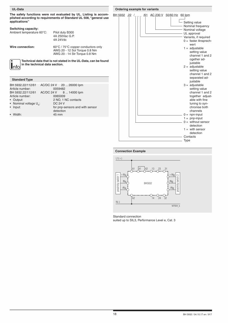
BH 5932.22/112/61 AC/DC 24 V 20 ... 26000 IpmArticle number: 0059482BH 5932.22/112/61 AC/DC 24 V 8 ... 14000 IpmArticle number: 0065009• Output: 2 NO, 1 NC contacts• Nominal voltage UN: DC 24 V• Input: for pnp-sensors and with sensor detection• Width: 45 mm
The safety functions were not evaluated by UL. Listing is accom-plished according to requirements of Standard UL 508, “general use applications”
Switching capacity:Ambient temperature 60°C: Pilot duty B300 4A 250Vac G.P. 4A 24Vdc
Wire connection: 60°C / 75°C copper conductors only AWG 20 - 12 Sol Torque 0.8 Nm AWG 20 - 14 Str Torque 0.8 Nm
nfoTechnical data that is not stated in the UL-Data, can be found in the technical data section.
UL-Data
Standard Type
Standard connectionsuited up to SIL3, Performance Level e, Cat. 3
A2
INA INB
-INA -INB
+INA +INB
M7604_b
A1 X1 X2 13
14N(-)
L1(+)
31
32
23
24
BH5932
prox
imity
switc
h2
prox
imity
switc
h1
BH 5932 .22 /_ _ _ /61 AC 230 V 50/60 Hz 60 Ipm Setting value Nominal frequency Nominal voltage UL approval Variants, if required 0 = fester Ansprech- wert 1 = adjustable setting value channel 1 and 2 ogether ad - justable 2 = adjustable setting value channel 1 and 2 separated ad - justable 3 = adjustable setting value channel 1 and 2 together adjust- able with fine tuning to syn- chro nise both channels 0 = npn-input 1 = pnp-input 0 = without sensor detection 1 = with sensor detection Contacts Type
Ordering example for variants
Connection Example

19 BH 5932 / 04.10.17 en / 917
Connection with external contactors,suited up to SIL3, Performance Level e, Cat. 3
A1(+)
On K4
K4
F2
S11 S12 S22 13 23 33 41
S21/PE
S33 S34 14 24 34 42 A2(-)
EntriegelungUnlockDévellouillage
F1
Off
StillstandswächterStand-Still-Monitor
Détecteur de vitesse zéroBH5932
Not-AusE-StopArrêt d'urgence
AufOpenOuvert
L1
L2
L3
N
Not-Aus-ModulE-Stop-Modul
Module d`arrêt d`urgenceBD5935
M6691_c
A1(+) X1
X2
31
32
13
14 A2(-)
23
24
K4
INA
+INA
-INA
INB
+INB
-INB
M3
A2
INB
INA
-INB
-INA
+INB
+INA
M10861
A1 X1 X2 13
14
N(-)
L1(+)
31
32
23
24
BH5932
Näh
erungssc
halter
Connection with proximity sensorssuited up to SIL2, Performance Level c, Cat. 2(to achieve Cat. 2 the safety function has to be tested on a regulare base.)
A2
INA INB
-INA -INB
+INA +INB
M7605_c
A1 X1 X2 13
14
N(-)
L1(+)
31
32
K3
K3 K4
K4
23
24
BH5932
pro
xim
ity
switch
2
pro
xim
ity
switch
1
suited up to SIL3, Performance Level e, Cat. 3
Connection Examples
Application Example
20 BH 5932 / 04.10.17 en / 917
TypeNA 5001.01.10 pnpNA 5001.01.20 npn
NA 5002.01.34pnp/npn
NA 5005.01.34pnp/npn
NA 5010.01.10 pnpNA 5010.01.20 npn
Dimensions
M6935_a
44
M8x1 SW13
braunschwarzblau 49
6065
M12 x 1 SW 17M6936_a
braunblau
schwarzweiß
M7032_a
456068
M 18 x 1 SW 24
braunblau
schwarzweiß
M7033_b
4960
80
M30 x 1,5 SW 36
braun
blauschwarz
Enclosure Metal Metal Metal Metal
Switching distance Sn 1 mm 2 mm 5 mm 10 mm
Switching frequency 5 000 Hz 1 000 Hz 300 Hz 200 Hz
Hysteresis 2 ... 10 %
Repeat accuracy 5 %
Voltage range 10 ... 30 V
Residual ripple < 10 %
Continuous current ≤ 200 mA ≤ 100 mA ≤ 100 mA ≤ 400 mA
Output .10 pnp NO
.20 npn NO
.34
pnp NO + npn NO
.34
pnp NO + npn NO
.10 pnp NO
.20 npn NO
Indication
of output state
LED
Ambient
temperature- 25 ... 70°C
Temperature influence 10 %
Degree of protection IP 67
Connection wire 2 m
Fixing torque 4 Nm 15 Nm 40 Nm 100 Nm
Weight 45 g 70 g 120 g 270 g
Connection Table BH 5932, BH 5932 / 00_
Type WireTerminal on
BH 5932
NA 5001.01.20
brown + + InA / + InB
blue - - InA / - InB
black NO InA / InB
NA 5002.01.34
NA 5005.01.34
brown + + InA / + InB
blanc NO InA / InB
blue - - InA / - InB
black - - InA / - InB
NA 5010.01.20
brown + + InA / + InB
blue - - InA / - InB
black NO InA / InB
Connection Table BH 5932, BH 5932 / 01_
Type WireTerminal on
BH 5932
NA 5001.01.10
brown + + InA / + InB
blue - - InA / - InB
black NO InA / InB
NA 5002.01.34
NA 5005.01.34
brown + + InA / + InB
blanc + + InA / + InB
blue - - InA / - InB
black NO InA / InB
NA 5010.01.10
brown + + InA / + InB
blue - - InA / - InB
black NO InA / InB
ATTENTION! Only the initiators NA5001.01.10, NA5001.01.20, NA5010.01.10 and NA5010.01.20 are usable for units with initiator-detection
(BH 5932.22/1xx) !
Initiators (proximity sensors), induktive
E. DOLD & SÖHNE KG • D-78114 Furtwangene-mail: [email protected] • internet: http://www.dold.com
• PO Box 1251 • Telephone (+49) 77 23 / 654-0 • Telefax (+49) 77 23 / 654-356

21 BH 5932 / 04.10.17 fr / 917
SAFEMASTER S Contrôleur de vitesse nulle ou lente BH 5932
Fiche Technique / Manuel d'utilisation FRANÇAIS
E. DOLD & SÖHNE KGB.P. 1251 • 78114 Furtwangen • AllemagneTél. +49 7723 6540 • Fax +49 7723 [email protected] • www.dold.com
Traduction de la notice originale
0263350
22 BH 5932 / 04.10.17 fr / 917
Tables des matières
Explication des symboles et remarques ..........................................................................................................................23
Remarques ......................................................................................................................................................................23
Usage approprié ..............................................................................................................................................................23
Consignes de sécurité .....................................................................................................................................................23
Diagramme de fonctionnement ........................................................................................................................................25
Schéma-bloc ....................................................................................................................................................................25
Homologations et sigles ..................................................................................................................................................25
Utilisation .........................................................................................................................................................................25
Affichages ........................................................................................................................................................................25
Schéma ...........................................................................................................................................................................25
Programmation de l‘appareil ............................................................................................................................................26
Remarques ......................................................................................................................................................................26
Caractéristiques techniques ............................................................................................................................................27
Versions standard ............................................................................................................................................................28
Exemple de commande de variantes ..............................................................................................................................28
Exemples de raccordement .............................................................................................................................................28
Exemples de raccordement .............................................................................................................................................29
Exemple d‘utilisation ........................................................................................................................................................29
Initiateurs (détecteur de proximité), inductifs .................................................................................................................30
Tableau de raccordement BH 5932, BH 5932 / 00_ ........................................................................................................30
Tableau de raccordement BH 5932, BH 5932 / 01_ ........................................................................................................30
Marquage et raccordements ............................................................................................................................................31
Dimensions (dimensions en mm) ....................................................................................................................................31
Montage / Démontage des borniers ammovibles ............................................................................................................31
Données techniques sécuritaires ....................................................................................................................................32
Déclaration de conformité européenne ...........................................................................................................................33
Note .................................................................................................................................................................................34
Note .................................................................................................................................................................................35
23 BH 5932 / 04.10.17 fr / 917
Consignes de sécurité
AVERTISSEMENT
Risque d'électrocution ! Danger de mort ou risque de blessure grave.• Assurez-vous que l'installation et l'appareil est et rese en l'état hors tension pendant l'installation électrique.• L'appareil peut uniquement être utilisé dans les cas d'application pré-
vus dans le mode d'emploi / la fiche technique. Les instructions de la documentation correspondante doivent être respectées. Les conditions ambiantes autorisées doivent être respectées.
• La protection de contact des éléments raccordés et l'isolation des câbles d'alimentation doivent être conçus conformément aux prescriptions du mode d'emploi/ fiche technique.
• Respecter les prescriptions de la VDE et les prescriptions locales, et tout particulièrement les mesures de sécurité.
AVERTISSEMENT
Risques d'incendie et autres risques thermiques ! Danger de mort, risque de blessure grave ou dégâts matériels. • L'appareil peut uniquement être utilisé dans les cas d'application pré-
vus dans le mode d'emploi / la fiche technique. Les instructions de la documentation correspondante doivent être respectées. Les conditions ambiantes autorisées doivent être respectées.
• L'appareil peut uniquement être installé et mis en service par un personnel dûment qualifié et familier avec la présente documentation technique et avec les prescriptions en vigueur relatives à la sécurité du travail et à la préservation de l'environnement.
AVERTISSEMENT
Erreur de fonctionnement ! Danger de mort, risque de blessure grave ou dégâts matériels. • L'appareil peut uniquement être utilisé dans les cas d'application pré-
vus dans le mode d'emploi / la fiche technique. Les instructions de la documentation correspondante doivent être respectées. Les conditions ambiantes autorisées doivent être respectées.
• L'appareil peut uniquement être installé et mis en service par un personnel dûment qualifié et familier avec la présente documentation technique et avec les prescriptions en vigueur relatives à la sécurité du travail et à la préservation de l'environnement.
• Le relais doit être monté en armoire ayant un indice de protection au moins IP 54; la poussière et l'humidité pouvant entraîner des disfonctionnements.
AVERTISSEMENT
Erreur d'installation ! Danger de mort, risque de blessure grave ou dégâts matériels. • Veillez à protéger suffisamment les contacts de sortie de charges ca-
pacitives et inductives.
! Attention! • La fonction de sécurité doit être activée lors de la mise en service.• L'ouverture de l'appareil ou des transformations non autorisées annulent la garantie.
DANGER
DANGER: Indique que la mort ou des blessures graves vont survenir en
cas de non respect des précautions demandées.
AVERTISSEMENT
AVERTISSEMENT: Indique que la mort ou des blessures graves peuvent survenir
si les précautions appropriées ne sont pas prises.
PRUDENCE
PRUDENCE: Signifie qu'une blessures légère peut survenir si les précautions
appropriées ne sont pas prises.
! ATTENTION:
Met en garde contre les actions qui peuvent causer des dommages au materiel Software ou hardware suite à un mauvais fonctionne-ment de l'appareil ou de l'environnement de l'appareil.
nfo INFO:
Concerne les informations qui vous sont mises à disposition pour le meilleur usage du produit.
Explication des symboles et remarques
L'installation ne doit être effectuée que par un electricien qualifié
Ne pas jeter aux ordures ménagères! L'appareil doit être éliminé conformément aux prescriptions et
directives nationales en vigueur.
Pour vous aider à comprendre et trouver des passages et des notes de texte spécifiques dans les instructions d'utilisation, nous avons marquées les informations importantes avec des symboles.
Avant l'installation, la mise en service ou l'entretien de cet appareil, on doit avoir lu et compris ce manuel d'utilisation.
Usage approprié
Le produit décrit ici a été développé pour remplir les fonctions de sécurité en tant qu'élément d'une installation globale ou d'une machine. Un systè-me de sécurité complet inclut habituellement des détecteurs ainsi que des modules d'évaluation, de signalisation et de logique aptes à déclencher des coupures de courant sûres. La responsabilité d'assurer la fiabilité de l'ensemble de la fonction incombe au fabricant de l'installation ou de la ma-chine. DOLD n'est pas en mesure de garantir toutes les caractéristiques d'une installation ou d'une machine dont la conception lui échappe. C'est à l'utilisateur de valider la conception globale du système auquel ce relais est connecté. DOLD ne prend en charge aucune responsabilité quant aux recommandations qui sont données ou impliquées par la description sui-vante. Sur la base du présent manuel d'utilisation, on ne pourra déduire aucune modification concernant les conditions générales de livraison de DOLD, les exigences de garantie ou de responsabilité.
Remarques
Le BH 5932 permet la surveillance de vitesse de rotation de de vitesse nulle.En cas d'emploi approprié et d'observation de ces instructions, on ne connaît aucun risque résiduel. Dans le cas contraire, on encourt des dommagescorporels et matériels.
Stockage pour référence future

24 BH 5932 / 04.10.17 fr / 917
25 BH 5932 / 04.10.17 fr / 917
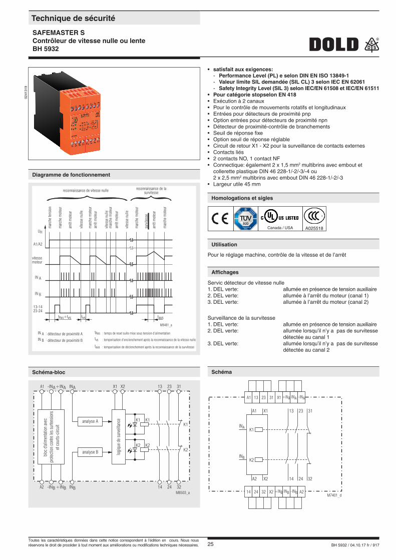
• satisfait aux exigences: - Performance Level (PL) e selon DIN EN ISO 13849-1 - Valeur limite SIL demandée (SIL CL) 3 selon IEC EN 62061 - Safety Integrity Level (SIL 3) selon IEC/EN 61508 et IEC/EN 61511
• Pour catégorie stopselon EN 418• Exécution à 2 canaux• Pour le contrôle de mouvements rotatifs et longitudinaux• Entrées pour détecteurs de proximité pnp• Option entrées pour détecteurs de proximité npn• Détecteur de proximité-contrôle de branchements• Seuil de réponse fixe• Option seuil de réponse réglable• Circuit de retour X1 - X2 pour la surveillance de contacts externes• Contacts liés• 2 contacts NO, 1 contact NF• Connectique: également 2 x 1,5 mm2 multibrins avec embout et collerette plastique DIN 46 228-1/-2/-3/-4 ou 2 x 2,5 mm2 multibrins avec embout DIN 46 228-1/-2/-3• Largeur utile 45 mm
0241
319
A1 13 23 31 X1 +INA
+INB
INA -INA
INA
INB -INB
INB
14 24 32 X2 A2M7401_d
K1
K2
13 23 31
14 24 32
A1 X1
A2 X2
t +tvsRes
tRes : temps de reset suite mise sous tension d’alimentation
tvs : temporisation d’enclenchement aprés la reconnaissance de la vitesse nulle
taus : temporisation de déclenchement aprés la reconnaissance de la survitesse
tvs taus
13-1423-24
arrê
tm
ote
ur
arrê
tm
ote
ur
arrê
tm
ote
ur
arrê
tm
ote
ur
vite
sse
nulle
vite
sse
nulle
vite
sse
nulle
mar
che
mote
ur
mar
che
tensi
on
reconnaissance de vitesse nullereconnaissance de la
survitesse
mar
che
mote
ur
mar
che
mote
ur
mar
che
mote
ur
mar
che
mote
ur
surv
ites
se
IN A
UH
A1/A2
IN B
IN A : détecteur de proximité A
IN B : détecteur de proximité B
vitessemoteur
M8481_a
M8503_a
A1
A2
INA+INA-INA
-INB+INB INB
K1
K2
K1
K2
32
K1
K2
3113 23
14 24
X1 X2
bloc
d'alim
enta
tion
avec
prot
ectio
nco
ntre
les
surte
nsio
nset
cour
ts-c
ircui
t
logi
que
desu
rvei
llanc
eanalyse A
analyse B
Pour le réglage machine, contrôle de la vitesse et de l’arrêt
Servic détecteur de vitesse nulle1. DEL verte: allumée en présence de tension auxiliaire2. DEL verte: allumée à l’arrêt du moteur (canal 1)3. DEL verte: allumée à l’arrêt du moteur (canal 2)
Surveillance de la survitesse1. DEL verte: allumée en présence de tension auxiliaire2. DEL verte: allumée lorsqu’il n’y a pas de survitesse détectée au canal 13. DEL verte: allumée lorsqu’il n’y a pas de survitesse détectée au canal 2
Canada / USA A025518
Technique de sécurité
SAFEMASTER SContrôleur de vitesse nulle ou lenteBH 5932
Diagramme de fonctionnement
Homologations et sigles
Utilisation
Affichages
SchémaSchéma-bloc
Toutes les caractéristiques données dans cette notice correspondent à l’édition en cours. Nous nous réservons le droit de procéder à tout moment aux améliorations ou modifications techniques nécessaires.
26 BH 5932 / 04.10.17 fr / 917
plaque
M28
13
Mettre l‘appareil hors tension avant de brancher les détecteurs.
*
plage* : 5-40 / 35-340 / 300-2700 / 1200-10500
ou 10-80 / 80-650 / 600-5300 / 2400-20000
xx-xx xx-xx xx-xx xx-xx
M9446
Version avec des canaux séparément réglables
Version avec vitesse de rotation réglable sur l´ensemble pour les 2 canaux et avec un ajustement précis de la simultanéité entre les canaux
L’appareil peut être utilisé pour la surveillance de la vitesse nulle et de vitesse lente. Tous les appareils sont bi-canaux.
VariantesTrois variantes sont disponibles:BH 5932.22/_ _0: Les appareils avec une vitesse de rotation fixeBH 5932.22/_ _2: Les appareils avec une vitesse de rotation réglée séparément pour les 2 canaux.BH 5932.22/_ _1: Les appareils avec une vitesse de rotation réglable pour les 2 canauxBH 5932.22/_ _3: Les appareils avec une vitesse de rotation réglable pour les 2 canaux, avec un ajustement précis du même temps de simultanéité.
Plage de la vitesse de rotationPour les appareils avec une vitesse de rotation réglable, la plage est divi-sée en 4 sous plages, qui au moyen d’un deuxième interrupteur DIP peut être choisie pour chaque canal. Pour le réglage de la vitesse de rotation dans les sous pages un potentiomètre sera utilisé.
Réglage de la plage de la vitesse de rotationLes impulsions à la minute utiles pour le réglage du point de commutation se calculent avec la formule donnée ci-dessous:
U/minute x le nombre de cames = IpmPar exemple: 7,5 U/min. x 2 cames =15 Ipm
Fonctionnement comme contrôleur de vitesse nulleLe réglage des deux canaux doit être fait de façon à ce que les 2 canaux s’enclenchent simultanément. Le temps maximal après la reconnaissance du temps d’arrêt jusqu’à l’enclenchement des relais de sortie dépend de la valeur Ipm réglée. Cette temporisation est calculée comme suit:
60 s + 2,5 s= tvsvaleur Ipm réglée
tvs temporisation d´enclenchement après la reconnaissance de la vitesse nulle
par exemple: pour un point de commutation réglé à 15 Ipm
60 s + 2,5 s = 6,5 s15
Fonctionnement en tant que contrôleur de vitesse de rotationsSurtout lors du contrôle de la survitesse il faut veiller á ce que le point de commutation des deux canaux soit réglée le plus exactement possible. Si les deux canaux ne déclenchent pas en même temps, l’entraînement ne sera coupé que par le canal le plus rapide. Ainsi la vitesse de rotati-on descend, si bien que le canal le plus lent ne peut plus reconnaître le dépassement de la vitesse de rotation et par conséquent ne peut provo-quer de coupure. Un des canaux ne s’étant pas éteint le redémarrage est bloqué et l’appareil ne peut être rallumé. Seule une coupure de la tension d’alimentation supprime le blocage du démarrage. Le réglage le plus pré-cis possible du point de commutation des deux canaux peut être facilité si la vitesse de contrôle à surveiller est le plus possible dans le milieu de la plage de la vitesse de rotation. Le réglage sur une commutation syn-chrone des deux canaux est plus simple sur les appareils dont le réglage des canaux est séparé que sur les appareils avec un ajustement précis complémentaire du point de commutation.
Détecteur inductifPour un fonctionnement sure il faut veiller au montage sans vibration du détecteur. La position des détecteurs doit être choisie afin que les deux impulsions ait lieu en même temps. Ici il faut veilleur a ce que les détec-teurs ne s’influencent pas mutuellement. Le branchement de l’interrupteur d’approximation á l’alimentation électrique doit être surveillé. Lors de l’interruption de l’alimentation d’un détecteur, le relais de sortie correspondant ne peut être enclenché ou le relais déjà enclenché se coupe aussitôt. Pour un fonctionnement sans anomalie le courant de repos du détecteur min est de 3 mA. Un fonctionnement avec détecteur à courant de repos plus petit peut être effectué en utilisant un appareil sans détectiopn de présence détecteur.Selon le EN ISO 13849-1, catégorie de sécurité 3, toutes les fonctions des détecteurs doivent être contrôlées à intervalle régulier.
Boucle de retour, reset, DELs et fenêtres de tempsLa boucle de retour X1-X2 doit être fermée avant la mise sous tension de l’appareil. Après la mise sous tension, l’appareil est fonctionnel après un temps typique de 1,5 s. Les DELs canal 1 et canal 2 sont allumées quand leurs relais sont enclen-chés. Les contacts de sortie ne seront toutefois activés que si les canaux répondent simultanément, sous 2s environ. Si les deux canaux ne sont pas là dans ce temps, à cause par exemple d´une panne d’un émetteur ou d’une mauvaise synchronisation des émetteurs, les contacts de sortie ne peuvent alors être déclenchés.
Version avec vitesse de rotation réglable sur l´ensemble pour les 2 canaux
Mettre l‘appareil hors tension avant de brancher les détecteurs.
*
plage* :
ou
8-60 / 60-450 / 450-3600 / 1800-14000
7-90 / 60-700 / 470-5500 / 1800-21000
xx-xx xx-xx xx-xx xx-xx
M10950
IpmIpm
IpmIpm
IpmIpm
*
plage* : 8-60 / 60-450 / 450-3600 / 1800-14000
ou 20-110 / 120-900 / 950-7000 / 3700-26000
M8504_a
xx-xx xx-xx xx-xx xx-xx
Programmation de l‘appareil Remarques
27 BH 5932 / 04.10.17 fr / 917
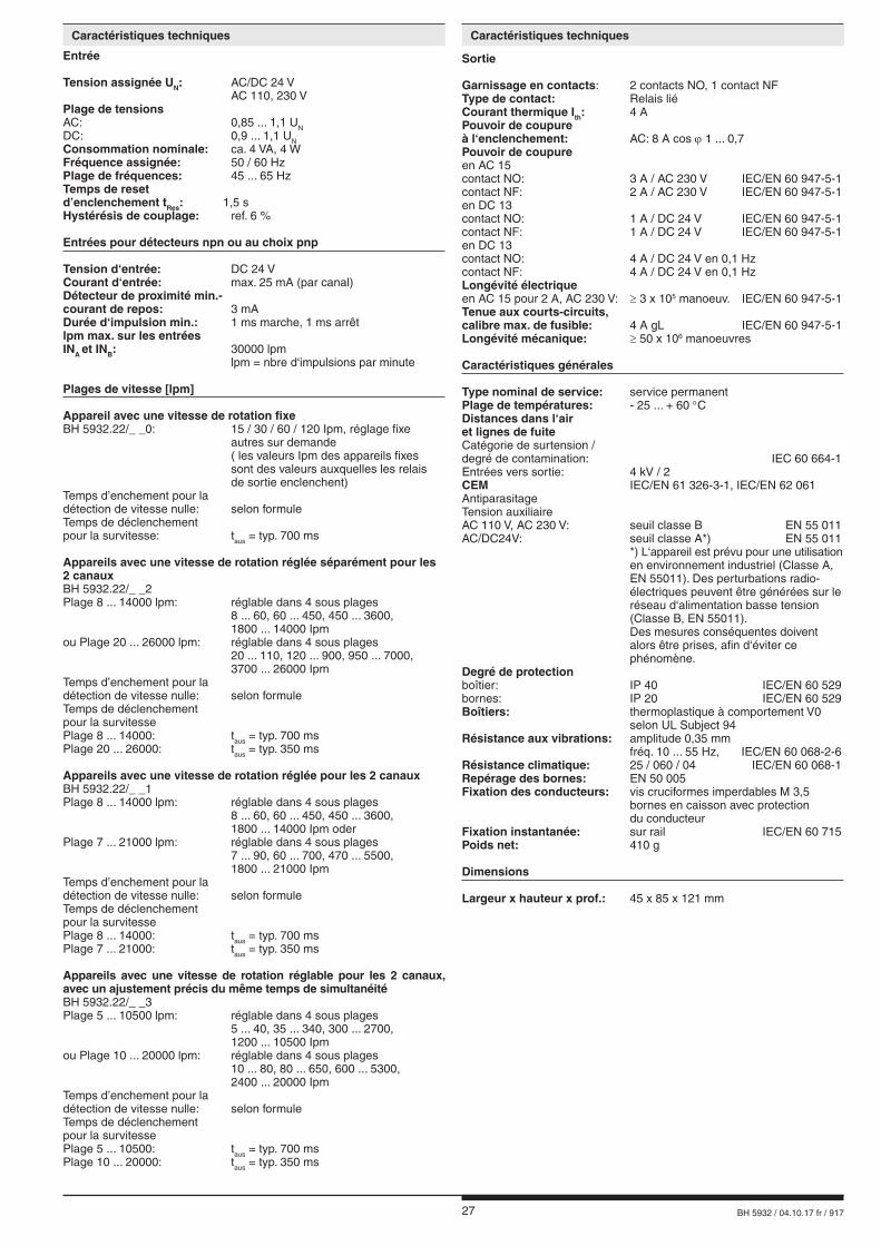
Entrée
Tension assignée UN: AC/DC 24 V AC 110, 230 VPlage de tensionsAC: 0,85 ... 1,1 UNDC: 0,9 ... 1,1 UNConsommation nominale: ca. 4 VA, 4 WFréquence assignée: 50 / 60 HzPlage de fréquences: 45 ... 65 HzTemps de reset d’enclenchement tRes: 1,5 sHystérésis de couplage: ref. 6 %
Entrées pour détecteurs npn ou au choix pnp
Tension d‘entrée: DC 24 VCourant d‘entrée: max. 25 mA (par canal)Détecteur de proximité min.-courant de repos: 3 mADurée d‘impulsion min.: 1 ms marche, 1 ms arrêtlpm max. sur les entréesINA et INB: 30000 lpm lpm = nbre d‘impulsions par minute
Plages de vitesse [lpm]
Appareil avec une vitesse de rotation fixeBH 5932.22/_ _0: 15 / 30 / 60 / 120 Ipm, réglage fixe autres sur demande ( les valeurs Ipm des appareils fixes sont des valeurs auxquelles les relais de sortie enclenchent)Temps d’enchement pour la détection de vitesse nulle: selon formule Temps de déclenchement pour la survitesse: taus = typ. 700 ms
Appareils avec une vitesse de rotation réglée séparément pour les 2 canauxBH 5932.22/_ _2Plage 8 ... 14000 lpm: réglable dans 4 sous plages 8 ... 60, 60 ... 450, 450 ... 3600, 1800 ... 14000 Ipmou Plage 20 ... 26000 lpm: réglable dans 4 sous plages 20 ... 110, 120 ... 900, 950 ... 7000, 3700 ... 26000 IpmTemps d’enchement pour la détection de vitesse nulle: selon formuleTemps de déclenchement pour la survitessePlage 8 ... 14000: taus = typ. 700 msPlage 20 ... 26000: taus = typ. 350 ms
Appareils avec une vitesse de rotation réglée pour les 2 canauxBH 5932.22/_ _1Plage 8 ... 14000 lpm: réglable dans 4 sous plages 8 ... 60, 60 ... 450, 450 ... 3600, 1800 ... 14000 Ipm oderPlage 7 ... 21000 lpm: réglable dans 4 sous plages 7 ... 90, 60 ... 700, 470 ... 5500, 1800 ... 21000 IpmTemps d’enchement pour la détection de vitesse nulle: selon formuleTemps de déclenchement pour la survitessePlage 8 ... 14000: taus = typ. 700 msPlage 7 ... 21000: taus = typ. 350 ms
Appareils avec une vitesse de rotation réglable pour les 2 canaux, avec un ajustement précis du même temps de simultanéitéBH 5932.22/_ _3Plage 5 ... 10500 lpm: réglable dans 4 sous plages 5 ... 40, 35 ... 340, 300 ... 2700, 1200 ... 10500 Ipmou Plage 10 ... 20000 lpm: réglable dans 4 sous plages 10 ... 80, 80 ... 650, 600 ... 5300, 2400 ... 20000 IpmTemps d’enchement pour la détection de vitesse nulle: selon formuleTemps de déclenchement pour la survitessePlage 5 ... 10500: taus = typ. 700 msPlage 10 ... 20000: taus = typ. 350 ms
Sortie
Garnissage en contacts: 2 contacts NO, 1 contact NFType de contact: Relais liéCourant thermique Ith: 4 APouvoir de coupureà l‘enclenchement: AC: 8 A cos ϕ 1 ... 0,7Pouvoir de coupureen AC 15contact NO: 3 A / AC 230 V IEC/EN 60 947-5-1contact NF: 2 A / AC 230 V IEC/EN 60 947-5-1en DC 13contact NO: 1 A / DC 24 V IEC/EN 60 947-5-1contact NF: 1 A / DC 24 V IEC/EN 60 947-5-1en DC 13contact NO: 4 A / DC 24 V en 0,1 Hz contact NF: 4 A / DC 24 V en 0,1 Hz Longévité électrique en AC 15 pour 2 A, AC 230 V: ≥ 3 x 10⁵ manoeuv. IEC/EN 60 947-5-1Tenue aux courts-circuits,calibre max. de fusible: 4 A gL IEC/EN 60 947-5-1Longévité mécanique: ≥ 50 x 106 manoeuvres
Caractéristiques générales
Type nominal de service: service permanentPlage de températures: - 25 ... + 60 °CDistances dans l‘airet lignes de fuiteCatégorie de surtension /degré de contamination: IEC 60 664-1Entrées vers sortie: 4 kV / 2CEM IEC/EN 61 326-3-1, IEC/EN 62 061AntiparasitageTension auxiliaire AC 110 V, AC 230 V: seuil classe B EN 55 011AC/DC24V: seuil classe A*) EN 55 011 *) L‘appareil est prévu pour une utilisation en environnement industriel (Classe A, EN 55011). Des perturbations radio- électriques peuvent être générées sur le réseau d‘alimentation basse tension (Classe B, EN 55011). Des mesures conséquentes doivent alors être prises, afin d‘éviter ce phénomène.Degré de protectionboîtier: IP 40 IEC/EN 60 529bornes: IP 20 IEC/EN 60 529Boîtiers: thermoplastique à comportement V0 selon UL Subject 94Résistance aux vibrations: amplitude 0,35 mm fréq. 10 ... 55 Hz, IEC/EN 60 068-2-6Résistance climatique: 25 / 060 / 04 IEC/EN 60 068-1Repérage des bornes: EN 50 005Fixation des conducteurs: vis cruciformes imperdables M 3,5 bornes en caisson avec protection du conducteurFixation instantanée: sur rail IEC/EN 60 715Poids net: 410 g
Dimensions
Largeur x hauteur x prof.: 45 x 85 x 121 mm
Caractéristiques techniquesCaractéristiques techniques
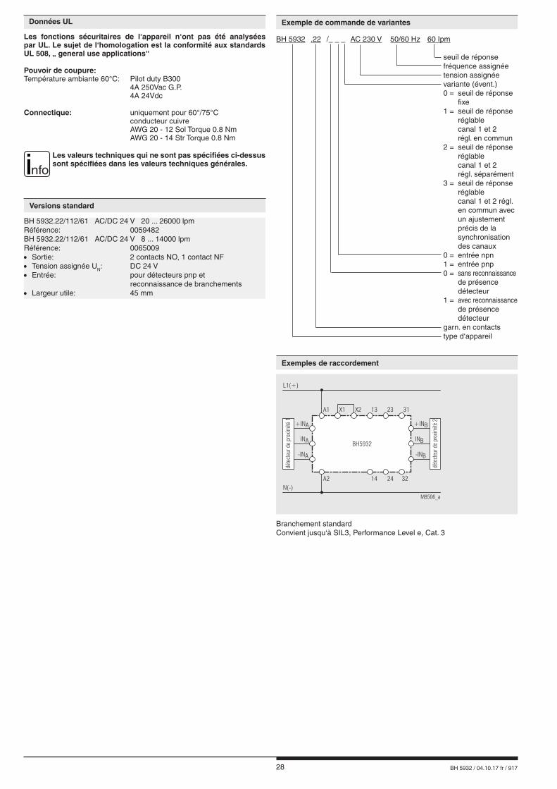
28 BH 5932 / 04.10.17 fr / 917
BH 5932.22/112/61 AC/DC 24 V 20 ... 26000 lpmRéférence: 0059482BH 5932.22/112/61 AC/DC 24 V 8 ... 14000 lpmRéférence: 0065009• Sortie: 2 contacts NO, 1 contact NF• Tension assignée UN: DC 24 V• Entrée: pour détecteurs pnp et reconnaissance de branchements• Largeur utile: 45 mm
Données UL
Les fonctions sécuritaires de l‘appareil n‘ont pas été analysées par UL. Le sujet de l‘homologation est la conformité aux standards UL 508, „ general use applications“
Pouvoir de coupure:Température ambiante 60°C: Pilot duty B300 4A 250Vac G.P. 4A 24Vdc
Connectique: uniquement pour 60°/75°C conducteur cuivre AWG 20 - 12 Sol Torque 0.8 Nm AWG 20 - 14 Str Torque 0.8 Nm
nfoLes valeurs techniques qui ne sont pas spécifiées ci-dessus sont spécifiées dans les valeurs techniques générales.
Versions standard
BH 5932 .22 /_ _ _ AC 230 V 50/60 Hz 60 Ipm seuil de réponse fréquence assignée tension assignée variante (évent.) 0 = seuil de réponse fixe 1 = seuil de réponse réglable canal 1 et 2 régl. en commun 2 = seuil de réponse réglable canal 1 et 2 régl. séparément 3 = seuil de réponse réglable canal 1 et 2 régl. en commun avec un ajustement précis de la synchronisation des canaux 0 = entrée npn 1 = entrée pnp 0 = sans reconnaissance de présence détecteur 1 = avec reconnaissance de présence détecteur garn. en contacts type d‘appareil
Branchement standardConvient jusqu‘à SIL3, Performance Level e, Cat. 3
A2
INA INB
-INA -INB
+INA +INB
M8506_a
A1 X1 X2 13
14N(-)
L1(+)
31
32
23
24
BH5932
déte
cteu
rde
prox
imité
1
déte
cteu
r de
prox
imité
2
Exemple de commande de variantes
Exemples de raccordement
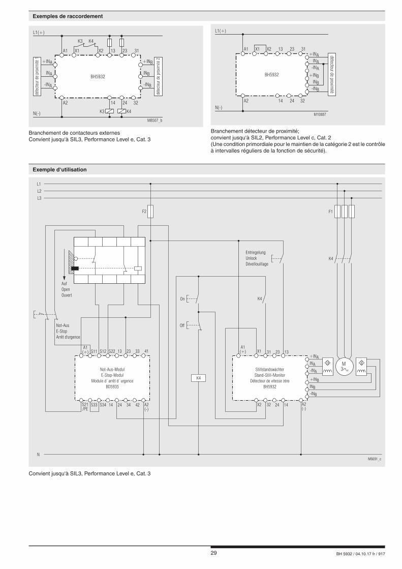
29 BH 5932 / 04.10.17 fr / 917
A1(+)
On K4
K4
F2
S11 S12 S22 13 23 33 41
S21/PE
S33 S34 14 24 34 42 A2(-)
EntriegelungUnlockDévellouillage
F1
Off
StillstandswächterStand-Still-Monitor
Détecteur de vitesse zéroBH5932
Not-AusE-StopArrêt d'urgence
AufOpenOuvert
L1
L2
L3
N
Not-Aus-ModulE-Stop-Modul
Module d`arrêt d`urgenceBD5935
M6691_c
A1(+) X1
X2
31
32
13
14 A2(-)
23
24
K4
INA
+INA
-INA
INB
+INB
-INB
M3
Branchement de contacteurs externesConvient jusqu‘à SIL3, Performance Level e, Cat. 3
A2
INA INB
-INA -INB
+INA +INB
M8507_b
A1 X1 X2 13
14
N(-)
L1(+)
31
32
K3
K3 K4
K4
23
24
BH5932
dét
ecte
ur
de
pro
xim
ité
1
dét
ecte
ur
de
pro
xim
ité
2
Convient jusqu‘à SIL3, Performance Level e, Cat. 3
A2
INB
INA
-INB
-INA
+INB
+INA
M10887
A1 X1 X2 13
14
N(-)
L1(+)
31
32
23
24
BH5932
détec
teur
de
pro
ximité
Branchement détecteur de proximité;convient jusqu‘à SIL2, Performance Level c, Cat. 2(Une condition primordiale pour le maintien de la catégorie 2 est le contrôle à intervalles réguliers de la fonction de sécurité).
Exemples de raccordement
Exemple d‘utilisation
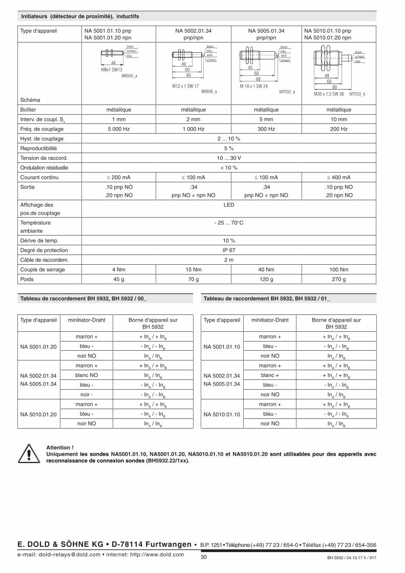
30 BH 5932 / 04.10.17 fr / 917
Type d‘appareil NA 5001.01.10 pnpNA 5001.01.20 npn
NA 5002.01.34pnp/npn
NA 5005.01.34pnp/npn
NA 5010.01.10 pnpNA 5010.01.20 npn
Schéma
M6935_a
44
M8x1 SW13
braunschwarzblau
496065
M12 x 1 SW 17M6936_a
braunblau
schwarzweiß
M7032_a
456068
M 18 x 1 SW 24
braunblau
schwarzweiß
M7033_b
4960
80
M30 x 1,5 SW 36
braun
blauschwarz
Boîtier métallique métallique métallique métallique
Interv. de coupl. Sn 1 mm 2 mm 5 mm 10 mm
Fréq. de couplage 5 000 Hz 1 000 Hz 300 Hz 200 Hz
Hyst. de couplage 2 ... 10 %
Reproductibilité 5 %
Tension de raccord. 10 ... 30 V
Ondulation résiduelle < 10 %
Courant continu ≤ 200 mA ≤ 100 mA ≤ 100 mA ≤ 400 mA
Sortie .10 pnp NO
.20 npn NO
.34
pnp NO + npn NO
.34
pnp NO + npn NO
.10 pnp NO
.20 npn NO
Affichage des
pos.de couplage
LED
Température
ambiante
- 25 ... 70°C
Dérive de temp. 10 %
Degré de protection IP 67
Câble de raccordem. 2 m
Couple de serrage 4 Nm 15 Nm 40 Nm 100 Nm
Poids 45 g 70 g 120 g 270 g
Tableau de raccordement BH 5932, BH 5932 / 00_
Type d‘appareil minitiator-Draht Borne d‘appareil surBH 5932
NA 5001.01.20
marron + + InA / + InB
bleu - - InA / - InB
noir NO InA / InB
NA 5002.01.34
NA 5005.01.34
marron + + InA / + InB
blanc NO InA / InB
bleu - - InA / - InB
noir - - InA / - InB
NA 5010.01.20
marron + + InA / + InB
bleu - - InA / - InB
noir NO InA / InB
Tableau de raccordement BH 5932, BH 5932 / 01_
Type d‘appareil minitiator-Draht Borne d‘appareil surBH 5932
NA 5001.01.10
marron + + InA / + InB
bleu - - InA / - InB
noir NO InA / InB
NA 5002.01.34
NA 5005.01.34
marron + + InA / + InB
blanc + + InA / + InB
bleu - - InA / - InB
noir NO InA / InB
NA 5010.01.10
marron + + InA / + InB
bleu - - InA / - InB
noir NO InA / InB
Attention ! Uniquement les sondes NA5001.01.10, NA5001.01.20, NA5010.01.10 et NA5010.01.20 sont utilisables pour des appareils avec
reconnaissance de connexion sondes (BH5932.22/1xx).
Initiateurs (détecteur de proximité), inductifs
E. DOLD & SÖHNE KG • D-78114 Furtwangene-mail: [email protected] • internet: http://www.dold.com
• B.P. 1251 • Téléphone (+49) 77 23 / 654-0 • Téléfax (+49) 77 23 / 654-356
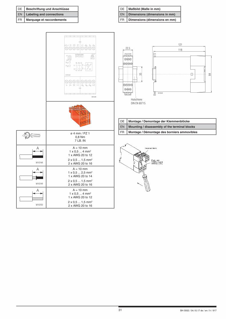
31 BH 5932 / 04.10.17 de / en / fr / 917
DE Beschriftung und Anschlüsse
EN Labeling and connections
FR Marquage et raccordements
M10049
121
118
84
22,5
Hutschiene
DIN EN 60715
35
DE Maßbild (Maße in mm)
EN Dimensions (dimensions in mm)
FR Dimensions (dimensions en mm)
DE Montage / Demontage der Klemmenblöcke
EN Mounting / disassembly of the terminal blocks
FR Montage / Démontage des borniers ammovibles
M10349
M20183_a
ø 4 mm / PZ 10,8 Nm7 LB. IN
M10248
A A = 10 mm1 x 0,5 ... 4 mm2
1 x AWG 20 to 12
2 x 0,5 ... 1,5 mm2
2 x AWG 20 to 16
M10249
A A = 10 mm1 x 0,5 ... 2,5 mm2
1 x AWG 20 to 14
2 x 0,5 ... 1,5 mm2
2 x AWG 20 to 16
M10250
A A = 10 mm1 x 0,5 ... 4 mm2
1 x AWG 20 to 12
2 x 0,5 ... 1,5 mm2
2 x AWG 20 to 16
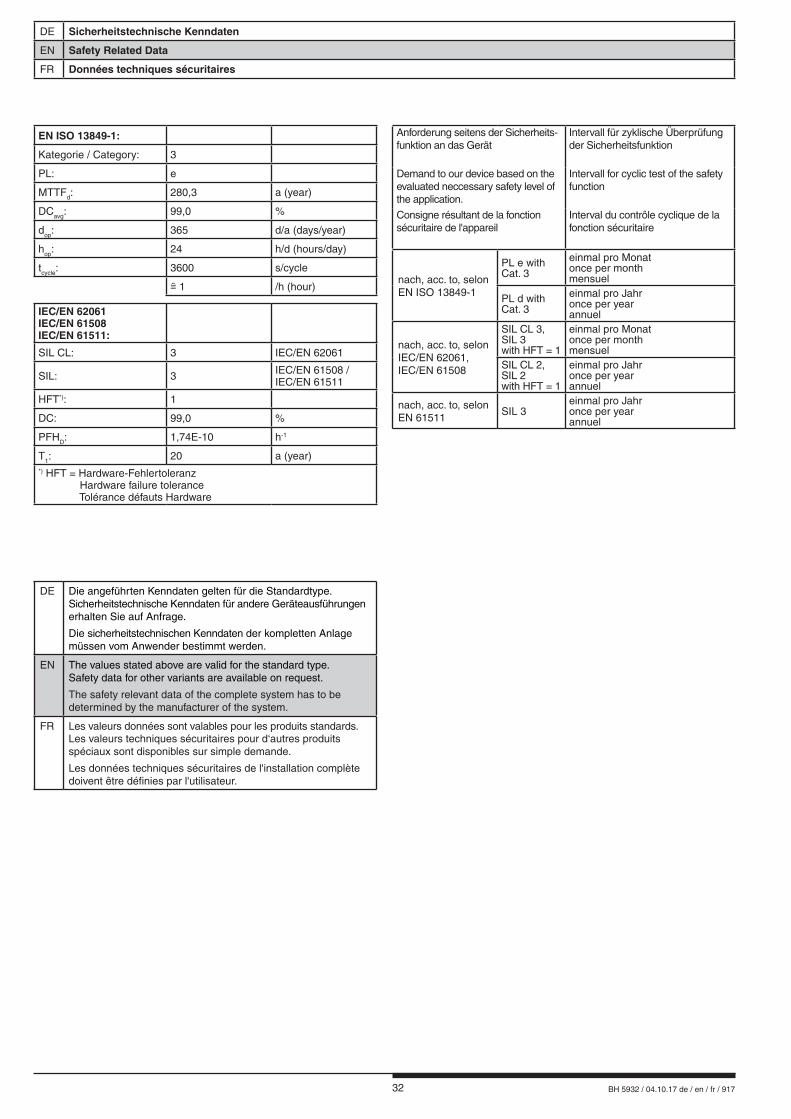
32 BH 5932 / 04.10.17 de / en / fr / 917
DE Sicherheitstechnische Kenndaten
EN Safety Related Data
FR Données techniques sécuritaires
DE Die angeführten Kenndaten gelten für die Standardtype. Sicherheitstechnische Kenndaten für andere Geräteausführungen erhalten Sie auf Anfrage.
Die sicherheitstechnischen Kenndaten der kompletten Anlagemüssen vom Anwender bestimmt werden.
EN The values stated above are valid for the standard type.Safety data for other variants are available on request.
The safety relevant data of the complete system has to be determined by the manufacturer of the system.
FR Les valeurs données sont valables pour les produits standards.Les valeurs techniques sécuritaires pour d‘autres produits spéciaux sont disponibles sur simple demande.
Les données techniques sécuritaires de l'installation complète doivent être définies par l'utilisateur.
EN ISO 13849-1:
Kategorie / Category: 3
PL: e
MTTFd: 280,3 a (year)
DCavg: 99,0 %
dop: 365 d/a (days/year)
hop: 24 h/d (hours/day)
tcycle: 3600 s/cycle
1 /h (hour)
IEC/EN 62061IEC/EN 61508IEC/EN 61511:
SIL CL: 3 IEC/EN 62061
SIL: 3 IEC/EN 61508 /IEC/EN 61511
HFT*): 1
DC: 99,0 %
PFHD: 1,74E-10 h-1
T1: 20 a (year)*) HFT = Hardware-Fehlertoleranz Hardware failure tolerance Tolérance défauts Hardware
Anforderung seitens der Sicherheits- funktion an das Gerät
Intervall für zyklische Überprüfung der Sicherheitsfunktion
Demand to our device based on the evaluated neccessary safety level of the application.
Intervall for cyclic test of the safety function
Consigne résultant de la fonction sécuritaire de l'appareil
Interval du contrôle cyclique de la fonction sécuritaire
nach, acc. to, selonEN ISO 13849-1
PL e with Cat. 3
einmal pro Monatonce per monthmensuel
PL d with Cat. 3
einmal pro Jahronce per yearannuel
nach, acc. to, selon IEC/EN 62061, IEC/EN 61508
SIL CL 3,SIL 3with HFT = 1
einmal pro Monatonce per monthmensuel
SIL CL 2,SIL 2with HFT = 1
einmal pro Jahronce per yearannuel
nach, acc. to, selon EN 61511
SIL 3einmal pro Jahronce per yearannuel
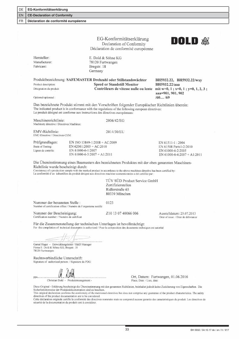
33 BH 5932 / 04.10.17 de / en / fr / 917
DE EG-Konformitätserklärung
EN CE-Declaration of Conformity
FR Déclaration de conformité européenne
34 BH 5932 / 04.10.17 de / en / fr / 917
DE Notizen
EN Notice
FR Note

35 BH 5932 / 04.10.17 de / en / fr / 917
DE Notizen
EN Notice
FR Note

36 BH 5932 / 04.10.17 de / en / fr / 917
E. DOLD & SÖHNE KG • D-78114 Furtwangene-mail: [email protected] • internet: http://www.dold.com
• Bregstraße 18 • Telefon 0 77 23 / 654-0 • Telefax 0 77 23 / 654-356