Embed Size (px)
Citation preview
ECHOGRAPH Ultrasonic Testing Electronics Examples for the Automated Component Testing
(Echograph1093 ComponentTest WD+Ti Oct07.doc)
KARL DEUTSCH Prüf- und Messgerätebau GmbH+Co KG Otto-Hausmann-Ring 101 D-42115 Wuppertal Tel (+49-202) 71 92 - 0 Fax (+49-202) 714 932 [email protected] Seite 1 von 9
ECHOGRAPH Ultrasonic Testing Electronics Examples for Automated Component Testing with Ultrasound Dr. (USA) Wolfram A. Karl Deutsch, Dr. rer.nat. Manfred Tietze
Dr.-Ing. Volker Schuster, Dipl.-Ing. Marcus Lok, Dipl.-Phys. Klaus Maxam
KARL DEUTSCH Prüf- und Messgerätebau GmbH + Co KG, Wuppertal
Tel.: (+49-202) 7192-0, Fax: (+49-202) 714-932, [email protected], www.karldeutsch.de
Abstract A new multi-channel ultrasonic testing electronics, type ECHOGRAPH, is presented in this paper in several configurations. Ultrasonic testing is often used to detect internal defects. Ultrasonic testing can easily be automated because it is a fast method and the signals are available in electronic form. Several applications are presented such as testing of forged gear shafts, testing of ceramic bolts, cleanliness inspection on steel samples and the semi-automated testing of heavy steel plates. The low price of the new testing electronics will allow for many future applications in various industries. Introduction In the manufacturing industries there are many applications for automated ultrasonic testing during production. Here ultrasonic testing is used for location of discontinuities within the material under test. By experience the minimum size of a defect may range from approx. 0.5 mm onwards. This minimum size is related to metallic work pieces only and strongly depends on the test conditions. Especially the inspection of mass production parts within the automobile industries requires automated testing concepts where cycle time and through put speed is of paramount importance. Within this paper a recently developed multi-channel testing electronics is presented and some testing examples will be demonstrated out of the automobile and steel production industries. Overview of the ECHOGRAPH Testing Electronics A new multi-channel testing electronics has been developed to be implemented into smaller testing systems. The measurement system is based on the mobile ultrasonic test instrument ECHOGRAPGH 1090 which has been introduced in 2005. The comprehensive and comfortable operation of the unit and the fast recovery and high contrast screen respectively are still significant components of this innovative testing concept. Where the handheld unit ECHOGRAPGH 1090 operates with batteries the measurement system ECHOGRAPH 1093 is powered by line voltage. In addition its measurement channels are optimized to a high repetition pulse frequency where for each testing channel up to 3000 Hz are possible (this is 3000 testing cycles per second). The maximum repetition rate depends on the material characteristics of the work piece like sound propagation time of ultrasonic pulse waves. Depending on the configuration of the electronics you can use one A-scan representation per channel (typical display of ultrasonic signal amplitudes) which corresponds to ECHOGRAPH 1092 or one can have a switchable A-scan (Type ECHOGRAPH 1093), which is just relevant for the operator during calibration of the system. A superior PC serves on the one hand as operating interface and as parameter store or can be used on the other hand for archiving or processing of testing results respectively. Depending on the testing task or where cost constraints require simplification, several test heads can be operated by multiplexing of signals via one and the same testing channel. During each subsequent cycle of the multiplexing electronics differences in signal gain and propagation time can be balanced accordingly for each individual test head. Just as well individual testing results per test head are back traceable.
ECHOGRAPH Ultrasonic Testing Electronics Examples for the Automated Component Testing
(Echograph1093 ComponentTest WD+Ti Oct07.doc)
KARL DEUTSCH Prüf- und Messgerätebau GmbH+Co KG Otto-Hausmann-Ring 101 D-42115 Wuppertal Tel (+49-202) 71 92 - 0 Fax (+49-202) 714 932 [email protected] Seite 2 von 9
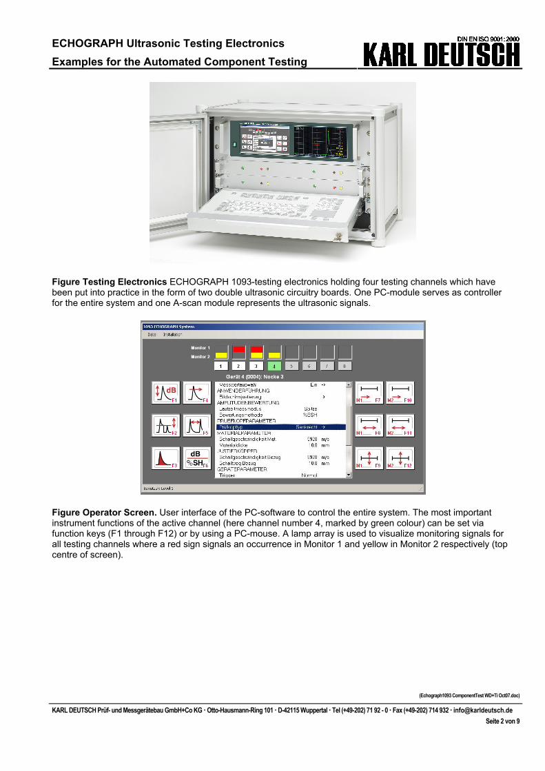
Figure Testing Electronics ECHOGRAPH 1093-testing electronics holding four testing channels which have been put into practice in the form of two double ultrasonic circuitry boards. One PC-module serves as controller for the entire system and one A-scan module represents the ultrasonic signals.
Figure Operator Screen. User interface of the PC-software to control the entire system. The most important instrument functions of the active channel (here channel number 4, marked by green colour) can be set via function keys (F1 through F12) or by using a PC-mouse. A lamp array is used to visualize monitoring signals for all testing channels where a red sign signals an occurrence in Monitor 1 and yellow in Monitor 2 respectively (top centre of screen).
ECHOGRAPH Ultrasonic Testing Electronics Examples for the Automated Component Testing
(Echograph1093 ComponentTest WD+Ti Oct07.doc)
KARL DEUTSCH Prüf- und Messgerätebau GmbH+Co KG Otto-Hausmann-Ring 101 D-42115 Wuppertal Tel (+49-202) 71 92 - 0 Fax (+49-202) 714 932 [email protected] Seite 3 von 9
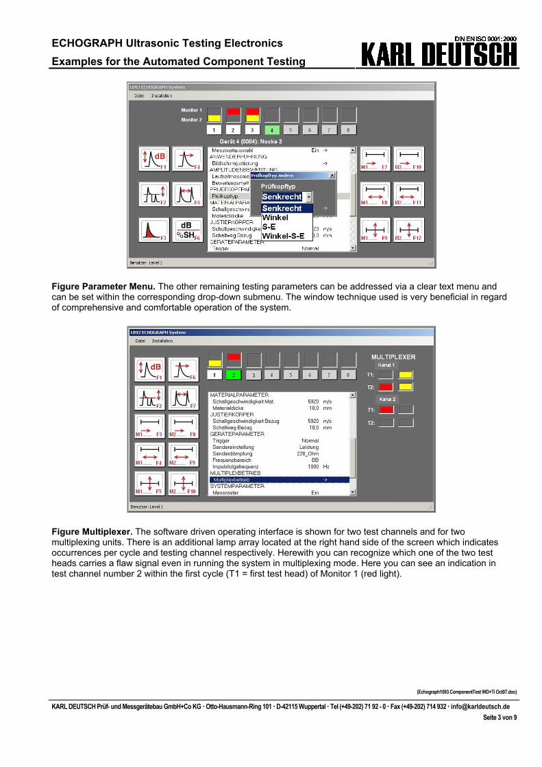
Figure Parameter Menu. The other remaining testing parameters can be addressed via a clear text menu and can be set within the corresponding drop-down submenu. The window technique used is very beneficial in regard of comprehensive and comfortable operation of the system.
Figure Multiplexer. The software driven operating interface is shown for two test channels and for two multiplexing units. There is an additional lamp array located at the right hand side of the screen which indicates occurrences per cycle and testing channel respectively. Herewith you can recognize which one of the two test heads carries a flaw signal even in running the system in multiplexing mode. Here you can see an indication in test channel number 2 within the first cycle (T1 = first test head) of Monitor 1 (red light).
ECHOGRAPH Ultrasonic Testing Electronics Examples for the Automated Component Testing
(Echograph1093 ComponentTest WD+Ti Oct07.doc)
KARL DEUTSCH Prüf- und Messgerätebau GmbH+Co KG Otto-Hausmann-Ring 101 D-42115 Wuppertal Tel (+49-202) 71 92 - 0 Fax (+49-202) 714 932 [email protected] Seite 4 von 9
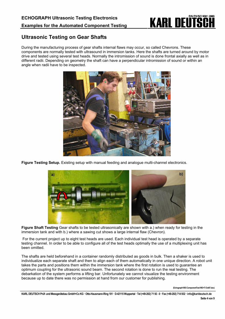
Ultrasonic Testing on Gear Shafts During the manufacturing process of gear shafts internal flaws may occur, so called Chevrons. These components are normally tested with ultrasound in immersion tanks. Here the shafts are turned around by motor drive and tested using several test heads. Normally the intromission of sound is done frontal axially as well as in different radii. Depending on geometry the shaft can have a perpendicular intromission of sound or within an angle when radii have to be inspected.
Figure Testing Setup. Existing setup with manual feeding and analogue multi-channel electronics.
Figure Shaft Testing Gear shafts to be tested ultrasonically are shown with a.) when ready for testing in the immersion tank and with b.) where a sawing cut shows a large internal flaw (Chevron).
For the current project up to eight test heads are used. Each individual test head is operated by a separate testing channel. In order to be able to configure all of the test heads optimally the use of a multiplexing unit has been omitted. The shafts are held beforehand in a container randomly distributed as goods in bulk. Then a shaker is used to individualize each separate shaft and then to align each of them automatically in one unique direction. A robot unit takes the parts and positions them within the immersion tank where the first rotation is used to guarantee an optimum coupling for the ultrasonic sound beam. The second rotation is done to run the real testing. The debarkation of the system performs a lifting bar. Unfortunately we cannot visualize the testing environment because up to date there was no permission at hand from our customer for publishing.
ECHOGRAPH Ultrasonic Testing Electronics Examples for the Automated Component Testing
(Echograph1093 ComponentTest WD+Ti Oct07.doc)
KARL DEUTSCH Prüf- und Messgerätebau GmbH+Co KG Otto-Hausmann-Ring 101 D-42115 Wuppertal Tel (+49-202) 71 92 - 0 Fax (+49-202) 714 932 [email protected] Seite 5 von 9
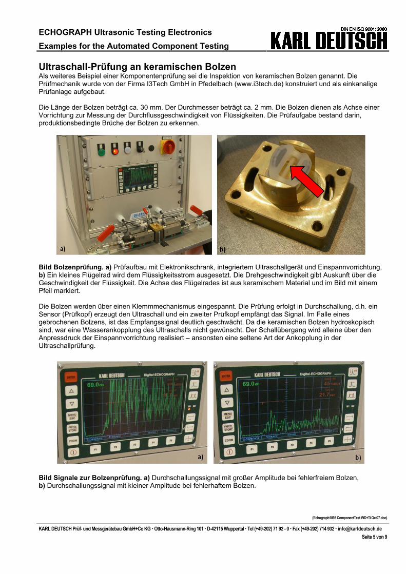
Ultraschall-Prüfung an keramischen Bolzen Als weiteres Beispiel einer Komponentenprüfung sei die Inspektion von keramischen Bolzen genannt. Die Prüfmechanik wurde von der Firma I3Tech GmbH in Pfedelbach (www.i3tech.de) konstruiert und als einkanalige Prüfanlage aufgebaut. Die Länge der Bolzen beträgt ca. 30 mm. Der Durchmesser beträgt ca. 2 mm. Die Bolzen dienen als Achse einer Vorrichtung zur Messung der Durchflussgeschwindigkeit von Flüssigkeiten. Die Prüfaufgabe bestand darin, produktionsbedingte Brüche der Bolzen zu erkennen.
Bild Bolzenprüfung. a) Prüfaufbau mit Elektronikschrank, integriertem Ultraschallgerät und Einspannvorrichtung, b) Ein kleines Flügelrad wird dem Flüssigkeitsstrom ausgesetzt. Die Drehgeschwindigkeit gibt Auskunft über die Geschwindigkeit der Flüssigkeit. Die Achse des Flügelrades ist aus keramischem Material und im Bild mit einem Pfeil markiert. Die Bolzen werden über einen Klemmmechanismus eingespannt. Die Prüfung erfolgt in Durchschallung, d.h. ein Sensor (Prüfkopf) erzeugt den Ultraschall und ein zweiter Prüfkopf empfängt das Signal. Im Falle eines gebrochenen Bolzens, ist das Empfangssignal deutlich geschwächt. Da die keramischen Bolzen hydroskopisch sind, war eine Wasserankopplung des Ultraschalls nicht gewünscht. Der Schallübergang wird alleine über den Anpressdruck der Einspannvorrichtung realisiert – ansonsten eine seltene Art der Ankopplung in der Ultraschallprüfung.
Bild Signale zur Bolzenprüfung. a) Durchschallungssignal mit großer Amplitude bei fehlerfreiem Bolzen, b) Durchschallungssignal mit kleiner Amplitude bei fehlerhaftem Bolzen.
ECHOGRAPH Ultrasonic Testing Electronics Examples for the Automated Component Testing
(Echograph1093 ComponentTest WD+Ti Oct07.doc)
KARL DEUTSCH Prüf- und Messgerätebau GmbH+Co KG Otto-Hausmann-Ring 101 D-42115 Wuppertal Tel (+49-202) 71 92 - 0 Fax (+49-202) 714 932 [email protected] Seite 6 von 9
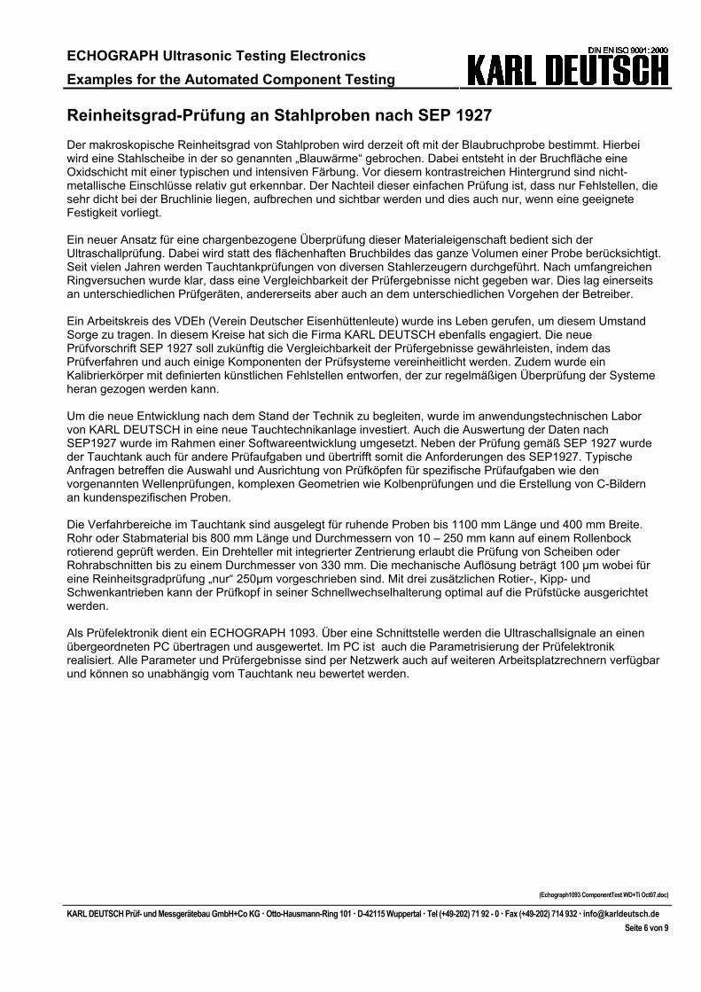
Reinheitsgrad-Prüfung an Stahlproben nach SEP 1927 Der makroskopische Reinheitsgrad von Stahlproben wird derzeit oft mit der Blaubruchprobe bestimmt. Hierbei wird eine Stahlscheibe in der so genannten „Blauwärme“ gebrochen. Dabei entsteht in der Bruchfläche eine Oxidschicht mit einer typischen und intensiven Färbung. Vor diesem kontrastreichen Hintergrund sind nicht-metallische Einschlüsse relativ gut erkennbar. Der Nachteil dieser einfachen Prüfung ist, dass nur Fehlstellen, die sehr dicht bei der Bruchlinie liegen, aufbrechen und sichtbar werden und dies auch nur, wenn eine geeignete Festigkeit vorliegt. Ein neuer Ansatz für eine chargenbezogene Überprüfung dieser Materialeigenschaft bedient sich der Ultraschallprüfung. Dabei wird statt des flächenhaften Bruchbildes das ganze Volumen einer Probe berücksichtigt. Seit vielen Jahren werden Tauchtankprüfungen von diversen Stahlerzeugern durchgeführt. Nach umfangreichen Ringversuchen wurde klar, dass eine Vergleichbarkeit der Prüfergebnisse nicht gegeben war. Dies lag einerseits an unterschiedlichen Prüfgeräten, andererseits aber auch an dem unterschiedlichen Vorgehen der Betreiber. Ein Arbeitskreis des VDEh (Verein Deutscher Eisenhüttenleute) wurde ins Leben gerufen, um diesem Umstand Sorge zu tragen. In diesem Kreise hat sich die Firma KARL DEUTSCH ebenfalls engagiert. Die neue Prüfvorschrift SEP 1927 soll zukünftig die Vergleichbarkeit der Prüfergebnisse gewährleisten, indem das Prüfverfahren und auch einige Komponenten der Prüfsysteme vereinheitlicht werden. Zudem wurde ein Kalibrierkörper mit definierten künstlichen Fehlstellen entworfen, der zur regelmäßigen Überprüfung der Systeme heran gezogen werden kann. Um die neue Entwicklung nach dem Stand der Technik zu begleiten, wurde im anwendungstechnischen Labor von KARL DEUTSCH in eine neue Tauchtechnikanlage investiert. Auch die Auswertung der Daten nach SEP1927 wurde im Rahmen einer Softwareentwicklung umgesetzt. Neben der Prüfung gemäß SEP 1927 wurde der Tauchtank auch für andere Prüfaufgaben und übertrifft somit die Anforderungen des SEP1927. Typische Anfragen betreffen die Auswahl und Ausrichtung von Prüfköpfen für spezifische Prüfaufgaben wie den vorgenannten Wellenprüfungen, komplexen Geometrien wie Kolbenprüfungen und die Erstellung von C-Bildern an kundenspezifischen Proben. Die Verfahrbereiche im Tauchtank sind ausgelegt für ruhende Proben bis 1100 mm Länge und 400 mm Breite. Rohr oder Stabmaterial bis 800 mm Länge und Durchmessern von 10 – 250 mm kann auf einem Rollenbock rotierend geprüft werden. Ein Drehteller mit integrierter Zentrierung erlaubt die Prüfung von Scheiben oder Rohrabschnitten bis zu einem Durchmesser von 330 mm. Die mechanische Auflösung beträgt 100 µm wobei für eine Reinheitsgradprüfung „nur“ 250µm vorgeschrieben sind. Mit drei zusätzlichen Rotier-, Kipp- und Schwenkantrieben kann der Prüfkopf in seiner Schnellwechselhalterung optimal auf die Prüfstücke ausgerichtet werden. Als Prüfelektronik dient ein ECHOGRAPH 1093. Über eine Schnittstelle werden die Ultraschallsignale an einen übergeordneten PC übertragen und ausgewertet. Im PC ist auch die Parametrisierung der Prüfelektronik realisiert. Alle Parameter und Prüfergebnisse sind per Netzwerk auch auf weiteren Arbeitsplatzrechnern verfügbar und können so unabhängig vom Tauchtank neu bewertet werden.
ECHOGRAPH Ultrasonic Testing Electronics Examples for the Automated Component Testing
(Echograph1093 ComponentTest WD+Ti Oct07.doc)
KARL DEUTSCH Prüf- und Messgerätebau GmbH+Co KG Otto-Hausmann-Ring 101 D-42115 Wuppertal Tel (+49-202) 71 92 - 0 Fax (+49-202) 714 932 [email protected] Seite 7 von 9
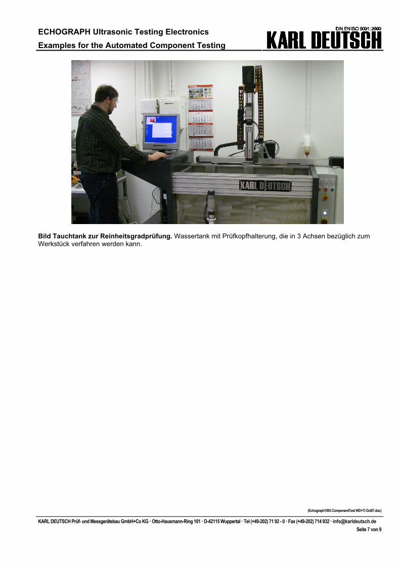
Bild Tauchtank zur Reinheitsgradprüfung. Wassertank mit Prüfkopfhalterung, die in 3 Achsen bezüglich zum Werkstück verfahren werden kann.
ECHOGRAPH Ultrasonic Testing Electronics Examples for the Automated Component Testing
(Echograph1093 ComponentTest WD+Ti Oct07.doc)
KARL DEUTSCH Prüf- und Messgerätebau GmbH+Co KG Otto-Hausmann-Ring 101 D-42115 Wuppertal Tel (+49-202) 71 92 - 0 Fax (+49-202) 714 932 [email protected] Seite 8 von 9
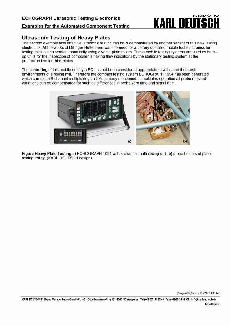
Ultrasonic Testing of Heavy Plates The second example how effective ultrasonic testing can be is demonstrated by another variant of this new testing electronics. At the works of Dillinger Hütte there was the need for a battery operated mobile test electronics for testing thick plates semi-automatically using diverse plate rollers. These mobile testing systems are used as back-up units for the inspection of components having flaw indications by the stationary testing system at the production line for thick plates. The controlling of this mobile unit by a PC has not been considered appropriate to withstand the harsh environments of a rolling mill. Therefore the compact testing system ECHOGRAPH 1094 has been generated which carries an 8-channel multiplexing unit. As already mentioned, in multiplex-operation all probe relevant variations can be compensated for such as differences in probe zero time and signal gain.
Figure Heavy Plate Testing a) ECHOGRAPH 1094 with 8-channel multiplexing unit, b) probe holders of plate testing trolley, (KARL DEUTSCH design).
ECHOGRAPH Ultrasonic Testing Electronics Examples for the Automated Component Testing
(Echograph1093 ComponentTest WD+Ti Oct07.doc)
KARL DEUTSCH Prüf- und Messgerätebau GmbH+Co KG Otto-Hausmann-Ring 101 D-42115 Wuppertal Tel (+49-202) 71 92 - 0 Fax (+49-202) 714 932 [email protected] Seite 9 von 9
Literature
[1] V. Deutsch, M. Platte, M. Vogt: Ultrasonic Testing – Basic Principles and Industrial Applications (in German language), Springer Publishing House, 1997.
[2] V. Deutsch, M. Platte, M. Vogt, W.A.K. Deutsch, V. Schuster: Ultrasonic Testing, Vol 1 of the series NDT Compact and Understandable, Castell Publishing House Wuppertal, 77 pages, 2002. [3] SEP 1927 Ultrasonic Immersion Testing Method for Determining the Macroscopic Degree of Purity of Rolled or Forged Steel Bars, VDEh, draft version September 2007.
[
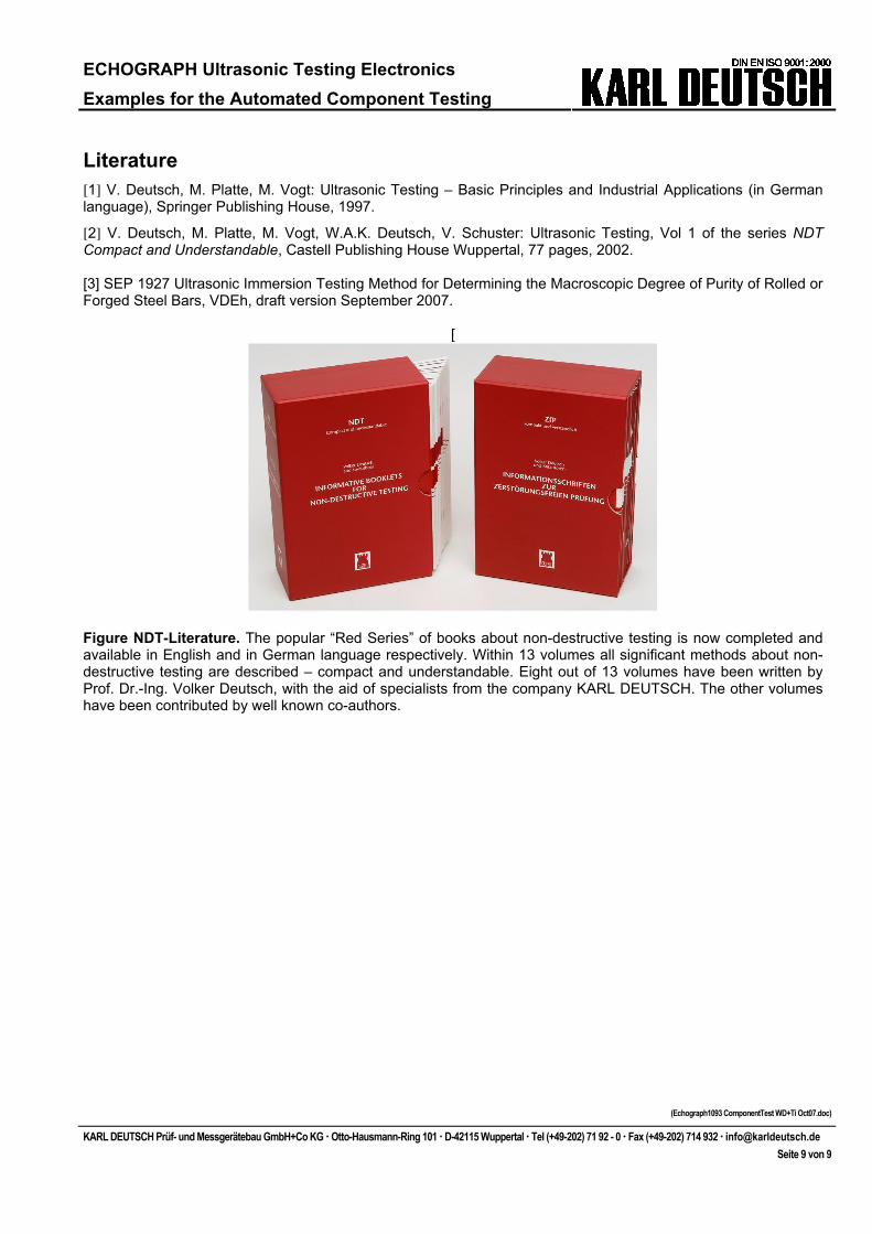
Figure NDT-Literature. The popular “Red Series” of books about non-destructive testing is now completed and available in English and in German language respectively. Within 13 volumes all significant methods about non-destructive testing are described – compact and understandable. Eight out of 13 volumes have been written by Prof. Dr.-Ing. Volker Deutsch, with the aid of specialists from the company KARL DEUTSCH. The other volumes have been contributed by well known co-authors.