Embed Size (px)
Citation preview
- 1 -
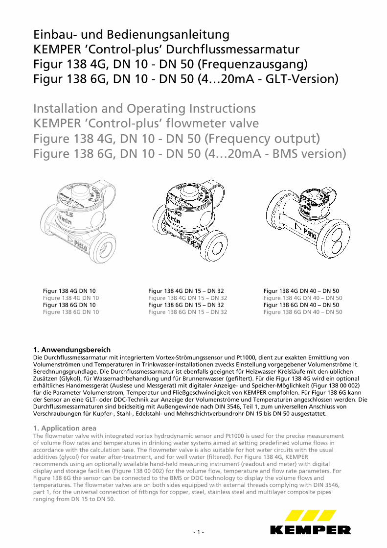
Einbau- und Bedienungsanleitung KEMPER ’Control-plus’ Durchflussmessarmatur Figur 138 4G, DN 10 - DN 50 (Frequenzausgang) Figur 138 6G, DN 10 - DN 50 (4…20mA - GLT-Version) Installation and Operating Instructions KEMPER ’Control-plus’ flowmeter valve Figure 138 4G, DN 10 - DN 50 (Frequency output) Figure 138 6G, DN 10 - DN 50 (4…20mA - BMS version)
Figur 138 4G DN 10 Figur 138 4G DN 15 – DN 32 Figur 138 4G DN 40 – DN 50 Figure 138 4G DN 10 Figure 138 4G DN 15 – DN 32 Figure 138 4G DN 40 – DN 50 Figur 138 6G DN 10 Figur 138 6G DN 15 – DN 32 Figur 138 6G DN 40 – DN 50 Figure 138 6G DN 10 Figure 138 6G DN 15 – DN 32 Figure 138 6G DN 40 – DN 50 1. Anwendungsbereich Die Durchflussmessarmatur mit integriertem Vortex-Strömungssensor und Pt1000, dient zur exakten Ermittlung von Volumenströmen und Temperaturen in Trinkwasser-Installationen zwecks Einstellung vorgegebener Volumenströme lt. Berechnungsgrundlage. Die Durchflussmessarmatur ist ebenfalls geeignet für Heizwasser-Kreisläufe mit den üblichen Zusätzen (Glykol), für Wassernachbehandlung und für Brunnenwasser (gefiltert). Für die Figur 138 4G wird ein optional erhältliches Handmessgerät (Auslese und Messgerät) mit digitaler Anzeige- und Speicher-Möglichkeit (Figur 138 00 002) für die Parameter Volumenstrom, Temperatur und Fließgeschwindigkeit von KEMPER empfohlen. Für Figur 138 6G kann der Sensor an eine GLT- oder DDC-Technik zur Anzeige der Volumenströme und Temperaturen angeschlossen werden. Die Durchflussmessarmaturen sind beidseitig mit Außengewinde nach DIN 3546, Teil 1, zum universellen Anschluss von Verschraubungen für Kupfer-, Stahl-, Edelstahl- und Mehrschichtverbundrohr DN 15 bis DN 50 ausgestattet. 1. Application area The flowmeter valve with integrated vortex hydrodynamic sensor and Pt1000 is used for the precise measurement of volume flow rates and temperatures in drinking water systems aimed at setting predefined volume flows in accordance with the calculation base. The flowmeter valve is also suitable for hot water circuits with the usual additives (glycol) for water after-treatment, and for well water (filtered). For Figure 138 4G, KEMPER recommends using an optionally available hand-held measuring instrument (readout and meter) with digital display and storage facilities (Figure 138 00 002) for the volume flow, temperature and flow rate parameters. For Figure 138 6G the sensor can be connected to the BMS or DDC technology to display the volume flows and temperatures. The flowmeter valves are on both sides equipped with external threads complying with DIN 3546, part 1, for the universal connection of fittings for copper, steel, stainless steel and multilayer composite pipes ranging from DN 15 to DN 50.
- 2 -
2. Funktion Die Funktion des Durchflusssensors basiert auf dem Prinzip der Karman’schen Wirbelstrasse. Die Wirbelablösung an dem in der Strömung stehenden Staukörper erfolgt proportional zur Strömungsgeschwindigkeit. Die erzeugten Wirbel werden durch ein piezoelektrisches Paddel detektiert und durch die integrierte Elektronik in ein Frequenzsignal umgewandelt. Zur Temperaturmessung ist zusätzlich im Staukörper ein Pt1000 integriert. Die Durchflussmessarmatur darf nicht für Durchflussmengen unterhalb des Messbereiches eingesetzt werden, da sich unterhalb des Messbereiches keine auswertbaren Wirbelströme ergeben. Diese Messergebnisse unterhalb des Messbereiches sind mit einem großen Fehler behaftet und daher falsch (auf Messbereich achten!). Bei Benutzung des KEMPER ´Control-plus´ Handmessgerätes (Auslese- und Messgerät, Figur 138 00 002) wird ein Unterschreiten des Messbereiches automatisch erkannt. 2. Function The function of the flowmeter sensor is based on the principle of Karman’s vortex trail. The vortices are shed at the damming body placed in the current in proportion to the flow rate. Any vortices created are detected via a piezoelectrical paddle and converted into a frequency signal by the integrated electronic circuits. A Pt1000 is additionally integrated in the damming body for measuring the temperature. The flowmeter valve may not be applied to throughflow volumes below the measuring range as no assessable vortices occur below this measuring range. The results of measurements taken below the measuring range are hence misleading and erroneous (please pay attention to the measuring range!). With the KEMPER portable 'Control-plus´ measuring device (reading and measuring device, Figure 138 00 002), any application below the measuring range is detected automatically. 3. Einbau und Montage Die Einbaulage ist grundsätzlich beliebig. Bei Gefahr von Ablagerungen in horizontalen Rohrleitungen wird empfohlen, den Sensor auf der Oberseite des Rohres zu montieren. In der Messstrecke dürfen keine Fremdkörper sein. Einbau Einlaufseite: nach Armaturen bzw. Formstücken mind. 5 x DN, nach Pumpen mind. 30 x DN Einbau Auslaufseite: Der Anschlussdurchmesser auf der Auslaufseite darf nicht kleiner als der Durchmesser der Armatur sein. ACHTUNG: Durchmessersprünge in Rohrleitungen sind ausschließlich nur von groß nach klein erlaubt, um Fehlmessungen zu vermeiden. 3. Installation and assembly The installation position is arbitrary as a matter of principle. If there is a risk of sediments being deposited in horizontal pipes, mounting the sensor on top of the pipe is recommended. The measuring section may not contain any foreign bodies. Inflow side installation: following valves and/or fittings a minimum of 5 x DN, following pumps a minimum of 30 x DN Outflow side installation: the connection diameter on the outflow side may not be smaller than the valve diameter. PLEASE NOTE: diameter leaps in pipes are only permissible from larger to smaller if faulty measurements are to be avoided. 4. Technische Eigenschaften 4. Technical attributes
Durchflussmessung (Figur 138 4G): Messbereich für Wasser: Throughflow Measurement: Measuring range for water:
DN Durchfluss (l/min.) Throughflow (l/min.)
Frequenz (f) Frequency (f)
Handmessgerät-Bereich Portable device range
Qmin - Qmax
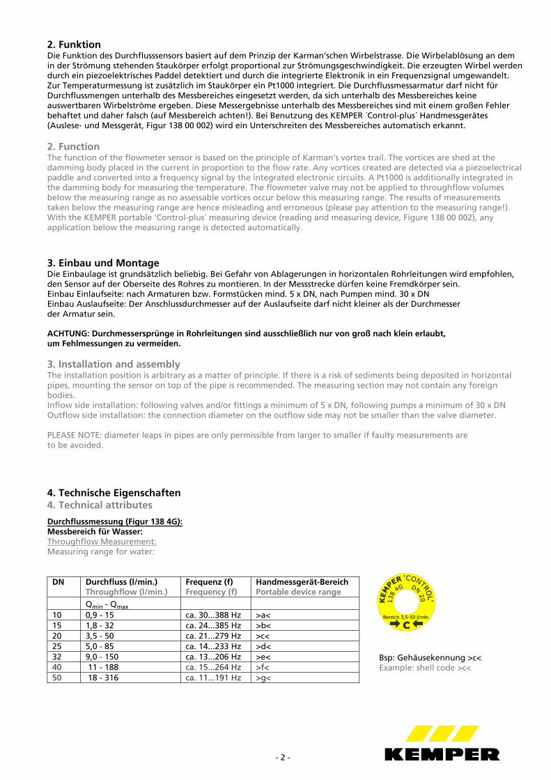
10 0,9 - 15 ca. 30...388 Hz >a< 15 1,8 - 32 ca. 24...385 Hz >b< 20 3,5 - 50 ca. 21...279 Hz >c< 25 5,0 - 85 ca. 14...233 Hz >d< 32 9,0 - 150 ca. 13...206 Hz >e< 40 11 - 188 ca. 15...264 Hz >f< 50 18 - 316 ca. 11...191 Hz >g<
Bsp: Gehäusekennung >c< Example: shell code >c<
- 3 -
Zur eindeutigen Kennzeichnung der entsprechenden Messbereiche des Sensors befindet sich bei jeder Sensordimension auf der Schutzkappe am oberen Gehäuse der entsprechende Buchstabe (z.B. >c<), um Fehleinstellungen bei der GLT oder dem optionalen Handmessgerät (Figur 138 00 002) zu vermeiden. Beispiel: Die Gehäusekennung >c< weist die Sensorgröße (oder Armaturengröße) DN 20 mit einem messbaren Durchfluss von 3,5 – 50 l/min und einer Frequenz f von ca. 21…279 Hz aus. For unequivocal identification of the sensor’s attendant measuring ranges, each sensor dimension on the protective cap of the upper shell is supplied with the relevant letter (e.g. >c<), in order to avoid erroneous settings in the central building control system or the optional portable measuring device (Figure 138 00 002). Example: shell code >c< indicates a DN 20 sensor size (or valve size) with a measurable throughflow of 3.5 – 50 l/min. and a frequency f of ca. 21…279 Hz. Durchflussmessung (Figur 138 6G): Messbereich für Wasser:
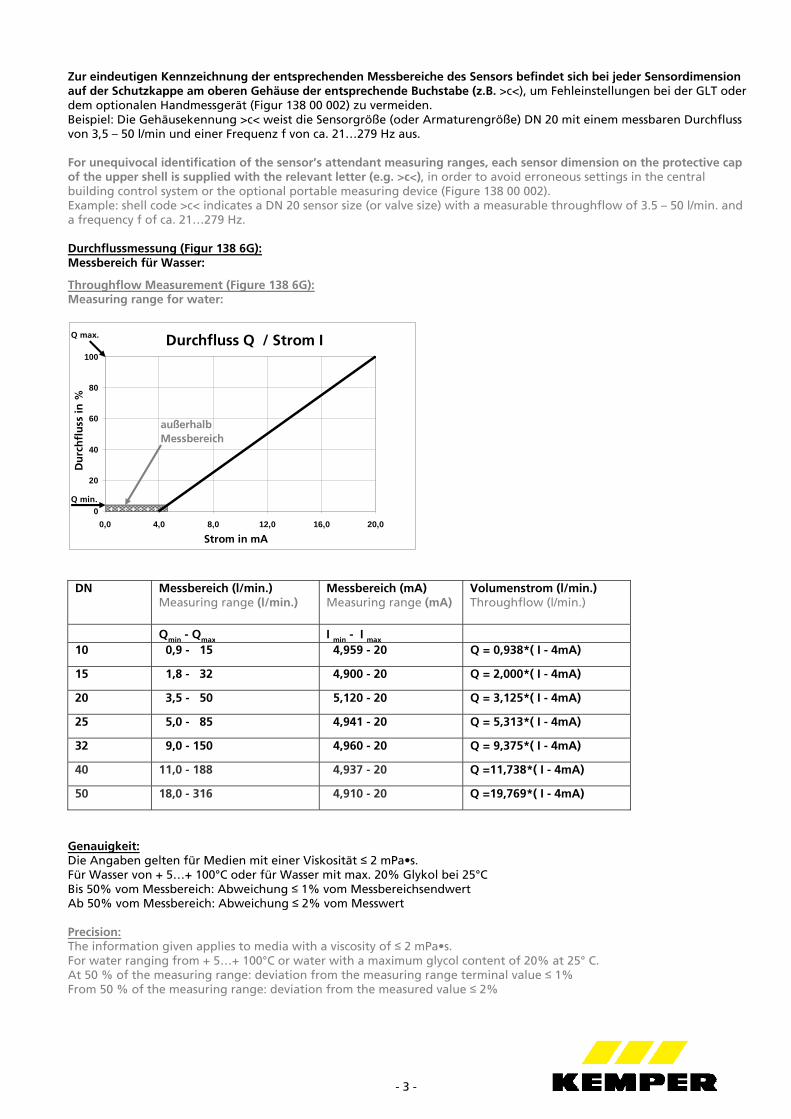
Throughflow Measurement (Figure 138 6G): Measuring range for water:
Durchfluss Q / Strom I
0
20
40
60
80
100
0,0 4,0 8,0 12,0 16,0 20,0
Strom in mA
Du
rch
flu
ss in
%
Q min.
Q max.
außerhalb Messbereich
DN Messbereich (l/min.) Measuring range (l/min.)
Messbereich (mA) Measuring range (mA)
Volumenstrom (l/min.) Throughflow (l/min.)
Qmin - Qmax I min - I max
10 0,9 - 15 4,959 - 20 Q = 0,938*( I - 4mA)
15 1,8 - 32 4,900 - 20 Q = 2,000*( I - 4mA)
20 3,5 - 50 5,120 - 20 Q = 3,125*( I - 4mA)
25 5,0 - 85 4,941 - 20 Q = 5,313*( I - 4mA)
32 9,0 - 150 4,960 - 20 Q = 9,375*( I - 4mA)
40 11,0 - 188 4,937 - 20 Q =11,738*( I - 4mA)
50 18,0 - 316 4,910 - 20 Q =19,769*( I - 4mA)
Genauigkeit: Die Angaben gelten für Medien mit einer Viskosität ≤ 2 mPa•s. Für Wasser von + 5…+ 100°C oder für Wasser mit max. 20% Glykol bei 25°C Bis 50% vom Messbereich: Abweichung ≤ 1% vom Messbereichsendwert Ab 50% vom Messbereich: Abweichung ≤ 2% vom Messwert Precision: The information given applies to media with a viscosity of ≤ 2 mPa•s. For water ranging from + 5…+ 100°C or water with a maximum glycol content of 20% at 25° C. At 50 % of the measuring range: deviation from the measuring range terminal value ≤ 1% From 50 % of the measuring range: deviation from the measured value ≤ 2%
- 4 -
Temperaturmessung: PT 1000 nach DIN EN 60751 Klasse B, 2-Leiter, z.B. +/- 0,45°C bei 20°C z.B. +/- 0,75°C bei 90°C Messbereich – 40 ... +150 °C
Temperature measurement: PT 1000 in compliance with DIN EN 60751 class B, two-core, e.g. +/- 0.45°C at 20°C e.g. +/- 0.75°C at 90°C Measuring range – 40 ... +150 °C
Toleranzgrenzen Fig. 1384G, DN15 - DN32
-20
-15
-10
-5
0
5
10
15
20
0 20 40 60 80 100
Durchflussmenge in %
Ab
we
ich
un
g v
om
Me
ss
we
rt in
%
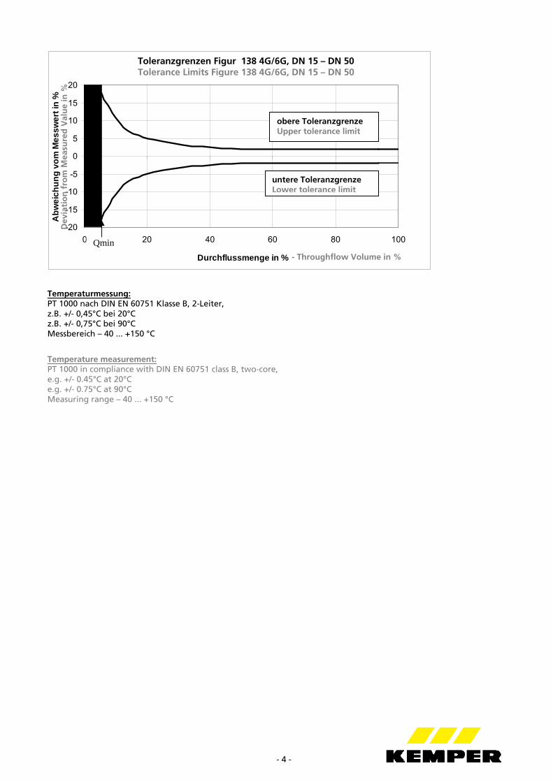
untere Toleranzgrenze Lower tolerance limit
obere Toleranzgrenze Upper tolerance limit
Qmin
- Throughflow Volume in %
Dev
iati
on
fro
m M
easu
red
Val
ue
in %
Toleranzgrenzen Figur 138 4G/6G, DN 15 – DN 50 Tolerance Limits Figure 138 4G/6G, DN 15 – DN 50
- 5 -
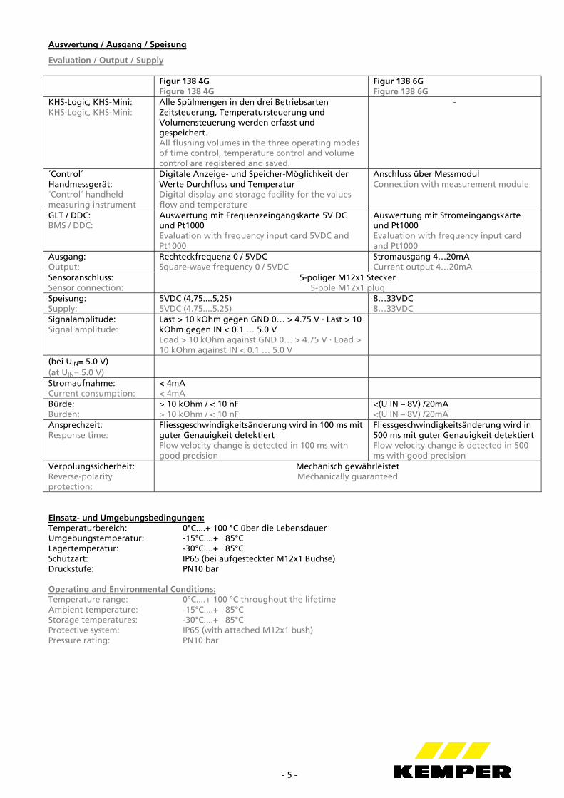
Auswertung / Ausgang / Speisung
Evaluation / Output / Supply Figur 138 4G
Figure 138 4G Figur 138 6G Figure 138 6G
KHS-Logic, KHS-Mini: KHS-Logic, KHS-Mini:
Alle Spülmengen in den drei Betriebsarten Zeitsteuerung, Temperatursteuerung und Volumensteuerung werden erfasst und gespeichert. All flushing volumes in the three operating modes of time control, temperature control and volume control are registered and saved.
-
´Control´ Handmessgerät: ´Control´ handheld measuring instrument
Digitale Anzeige- und Speicher-Möglichkeit der Werte Durchfluss und Temperatur Digital display and storage facility for the values flow and temperature
Anschluss über Messmodul Connection with measurement module
GLT / DDC: BMS / DDC:
Auswertung mit Frequenzeingangskarte 5V DC und Pt1000 Evaluation with frequency input card 5VDC and Pt1000
Auswertung mit Stromeingangskarte und Pt1000 Evaluation with frequency input card and Pt1000
Ausgang: Output:
Rechteckfrequenz 0 / 5VDC Square-wave frequency 0 / 5VDC
Stromausgang 4…20mA Current output 4…20mA
Sensoranschluss: Sensor connection:
5-poliger M12x1 Stecker 5-pole M12x1 plug
Speisung: Supply:
5VDC (4,75....5,25) 5VDC (4.75....5.25)
8…33VDC 8…33VDC
Signalamplitude: Signal amplitude:
Last > 10 kOhm gegen GND 0… > 4.75 V · Last > 10 kOhm gegen IN < 0.1 … 5.0 V Load > 10 kOhm against GND 0… > 4.75 V · Load > 10 kOhm against IN < 0.1 … 5.0 V
(bei UIN= 5.0 V) (at UIN= 5.0 V)
Stromaufnahme: Current consumption:
< 4mA < 4mA
Bürde: Burden:
> 10 kOhm / < 10 nF > 10 kOhm / < 10 nF
<(U IN – 8V) /20mA <(U IN – 8V) /20mA
Ansprechzeit: Response time:
Fliessgeschwindigkeitsänderung wird in 100 ms mit guter Genauigkeit detektiert Flow velocity change is detected in 100 ms with good precision
Fliessgeschwindigkeitsänderung wird in 500 ms mit guter Genauigkeit detektiert Flow velocity change is detected in 500 ms with good precision
Verpolungssicherheit: Reverse-polarity protection:
Mechanisch gewährleistet Mechanically guaranteed
Einsatz- und Umgebungsbedingungen: Temperaturbereich: 0°C....+ 100 °C über die Lebensdauer Umgebungstemperatur: -15°C....+ 85°C Lagertemperatur: -30°C....+ 85°C Schutzart: IP65 (bei aufgesteckter M12x1 Buchse) Druckstufe: PN10 bar Operating and Environmental Conditions: Temperature range: 0°C....+ 100 °C throughout the lifetime Ambient temperature: -15°C....+ 85°C Storage temperatures: -30°C....+ 85°C Protective system: IP65 (with attached M12x1 bush) Pressure rating: PN10 bar
- 6 -
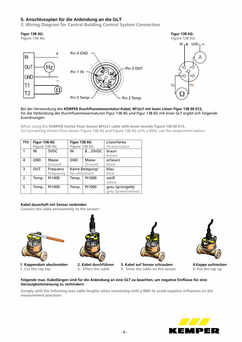
5. Anschlussplan für die Anbindung an die GLT 5. Wiring Diagram for Central Building Control System Connection Figur 138 4G: Figur 138 6G: Figure 138 4G: Figure 138 6G:
Bei der Verwendung des KEMPER Durchflussmessarmatur-Kabel, M12x1 mit losen Litzen Figur 138 00 012, für die Verbindung der Durchflussmessarmaturen Figur 138 4G und Figur 138 6G mit einer GLT ergibt sich folgende Zuordnungen: When using the KEMPER Vortex Flow Sensor M12x1 cable with loose strands Figure 138 00 012, for connecting Vortex Flow Sensor Figure 138 4G and Figure 138 6G with a BMS, use the assignments below:
PIN Figur 138 4G Figure 138 4G
Figur 138 6G Figure 138 6G
Litzenfarbe Strand colour
1 IN 5VDC IN 8…33VDC braun brown
4 GND Masse Ground
GND Masse Ground
schwarz black
3 OUT Frequenz Frequency
Keine Belegung! No allocation!
blau blue
2 Temp. Pt1000 Temp. Pt1000 weiß white
5 Temp. Pt1000 Temp. Pt1000 grau (grün/gelb) grey (green/yellow)
Kabel dauerhaft mit Sensor verbinden Connect the cable permanently to the sensor!
Folgende max. Kabellängen sind für die Anbindung an eine GLT zu beachten, um negative Einflüsse für eine Genauigkeitsmessung zu verhindern:
Comply with the following max cable lengths when connecting with a BMS to avoid negative influences on the measurement precision:
1. Kappendom abschneiden 2. Kabel durchführen 3. Kabel auf Sensor schrauben 4.Kappe aufstecken 1. Cut the cap top 2. Effect the cable 3. Srew the cable on the sensor 4. Put the cap up
- 7 -
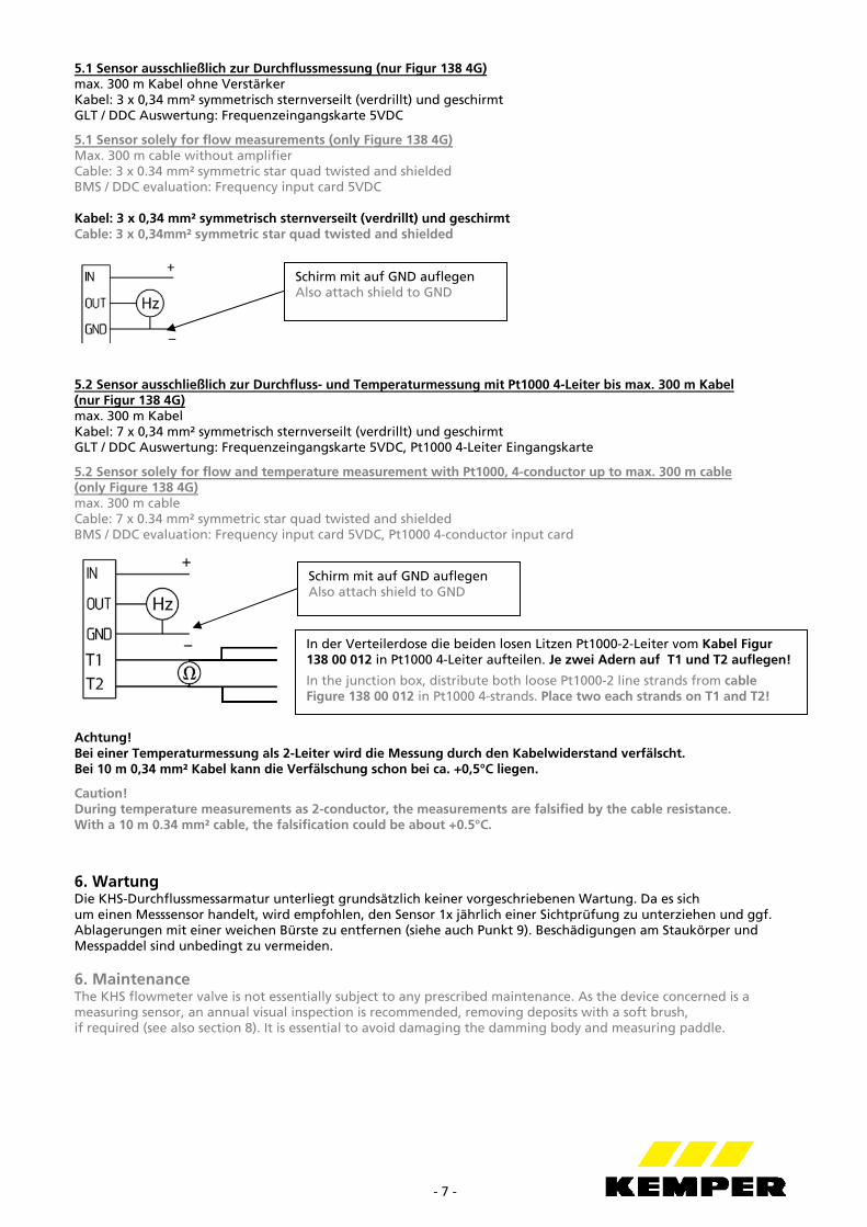
5.1 Sensor ausschließlich zur Durchflussmessung (nur Figur 138 4G) max. 300 m Kabel ohne Verstärker Kabel: 3 x 0,34 mm² symmetrisch sternverseilt (verdrillt) und geschirmt GLT / DDC Auswertung: Frequenzeingangskarte 5VDC
5.1 Sensor solely for flow measurements (only Figure 138 4G) Max. 300 m cable without amplifier Cable: 3 x 0.34 mm² symmetric star quad twisted and shielded BMS / DDC evaluation: Frequency input card 5VDC Kabel: 3 x 0,34 mm² symmetrisch sternverseilt (verdrillt) und geschirmt Cable: 3 x 0,34mm² symmetric star quad twisted and shielded
5.2 Sensor ausschließlich zur Durchfluss- und Temperaturmessung mit Pt1000 4-Leiter bis max. 300 m Kabel (nur Figur 138 4G) max. 300 m Kabel Kabel: 7 x 0,34 mm² symmetrisch sternverseilt (verdrillt) und geschirmt GLT / DDC Auswertung: Frequenzeingangskarte 5VDC, Pt1000 4-Leiter Eingangskarte
5.2 Sensor solely for flow and temperature measurement with Pt1000, 4-conductor up to max. 300 m cable (only Figure 138 4G) max. 300 m cable Cable: 7 x 0.34 mm² symmetric star quad twisted and shielded BMS / DDC evaluation: Frequency input card 5VDC, Pt1000 4-conductor input card
Achtung! Bei einer Temperaturmessung als 2-Leiter wird die Messung durch den Kabelwiderstand verfälscht. Bei 10 m 0,34 mm² Kabel kann die Verfälschung schon bei ca. +0,5°C liegen.
Caution! During temperature measurements as 2-conductor, the measurements are falsified by the cable resistance. With a 10 m 0.34 mm² cable, the falsification could be about +0.5°C.
6. Wartung Die KHS-Durchflussmessarmatur unterliegt grundsätzlich keiner vorgeschriebenen Wartung. Da es sich um einen Messsensor handelt, wird empfohlen, den Sensor 1x jährlich einer Sichtprüfung zu unterziehen und ggf. Ablagerungen mit einer weichen Bürste zu entfernen (siehe auch Punkt 9). Beschädigungen am Staukörper und Messpaddel sind unbedingt zu vermeiden. 6. Maintenance The KHS flowmeter valve is not essentially subject to any prescribed maintenance. As the device concerned is a measuring sensor, an annual visual inspection is recommended, removing deposits with a soft brush, if required (see also section 8). It is essential to avoid damaging the damming body and measuring paddle.
Schirm mit auf GND auflegen Also attach shield to GND
In der Verteilerdose die beiden losen Litzen Pt1000-2-Leiter vom Kabel Figur 138 00 012 in Pt1000 4-Leiter aufteilen. Je zwei Adern auf T1 und T2 auflegen!
In the junction box, distribute both loose Pt1000-2 line strands from cable Figure 138 00 012 in Pt1000 4-strands. Place two each strands on T1 and T2!
Schirm mit auf GND auflegen Also attach shield to GND
- 8 -
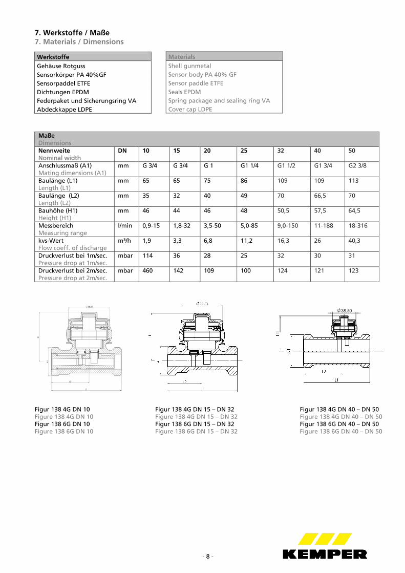
7. Werkstoffe / Maße 7. Materials / Dimensions
Werkstoffe Gehäuse Rotguss Sensorkörper PA 40%GF Sensorpaddel ETFE Dichtungen EPDM Federpaket und Sicherungsring VA Abdeckkappe LDPE
Figur 138 4G DN 10 Figur 138 4G DN 15 – DN 32 Figur 138 4G DN 40 – DN 50 Figure 138 4G DN 10 Figure 138 4G DN 15 – DN 32 Figure 138 4G DN 40 – DN 50 Figur 138 6G DN 10 Figur 138 6G DN 15 – DN 32 Figur 138 6G DN 40 – DN 50 Figure 138 6G DN 10 Figure 138 6G DN 15 – DN 32 Figure 138 6G DN 40 – DN 50
Maße Dimensions Nennweite Nominal width
DN 10 15 20 25 32 40 50
Anschlussmaß (A1) Mating dimensions (A1)
mm G 3/4 G 3/4 G 1 G1 1/4 G1 1/2 G1 3/4 G2 3/8
Baulänge (L1) Length (L1)
mm 65 65 75 86 109 109 113
Baulänge (L2) Length (L2)
mm 35 32 40 49 70 66,5 70
Bauhöhe (H1) Height (H1)
mm 46 44 46 48 50,5 57,5 64,5
Messbereich Measuring range
l/min 0,9-15 1,8-32 3,5-50 5,0-85 9,0-150 11-188 18-316
kvs-Wert Flow coeff. of discharge
m³/h 1,9 3,3 6,8 11,2 16,3 26 40,3
Druckverlust bei 1m/sec. Pressure drop at 1m/sec.
mbar 114 36 28 25 32 30 31
Druckverlust bei 2m/sec. Pressure drop at 2m/sec.
mbar 460 142 109 100 124 121 123
Materials Shell gunmetal Sensor body PA 40% GF Sensor paddle ETFE Seals EPDM Spring package and sealing ring VA Cover cap LDPE
- 9 -
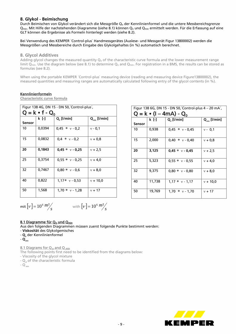
8. Glykol - Beimischung Durch Beimischen von Glykol verändert sich die Messgröße Qo der Kennlinienformel und die untere Messbereichsgrenze Qmin. Mit Hilfe der nachstehenden Diagramme (siehe 8.1) können Qo und Qmin ermittelt werden. Für die Erfassung auf eine GLT können die Ergebnisse als Formeln hinterlegt werden (siehe 8.2). Bei Verwendung des KEMPER ´Control-plus` Handmessgerätes (Auslese- und Messgerät Figur 13800002) werden die Messgrößen und Messbereiche durch Eingabe des Glykolgehaltes (in %) automatisch berechnet. 8. Glycol Additives Adding glycol changes the measured quantity Qo of the characteristic curve formula and the lower measurement range limit Qmin. Use the diagram below (see 8.1) to determine Qo and Qmin. For registration in a BMS, the results can be stored as formulas (see 8.2). When using the portable KEMPER ´Control-plus` measuring device (reading and measuring device Figure13800002), the measured quantities and measuring ranges are automatically calculated following entry of the glycol contents (in %). Kennlinienformeln Characteristic curve formula
Figur 138 4G, DN 15 - DN 50,´Control-plus´,
Q = k • f - Q0 Sensor
k [-] Q0 [l/min] Qmin [l/min]
10 0,0394 0,45 - 0,2 - 0,1
15 0,0832 0,4 - 0,2 + 0,8
20 0,1843 0,45 - 0,25 + 2,5
25 0,3754 0,55 - 0,25 + 4,0
32 0,7467 0,80 - 0,6 + 8,0
40 0,822 1,17 - 0,53 + 10,0
50 1,568 1,70 - 1,28 + 17
mit sm²106 with s
m²106
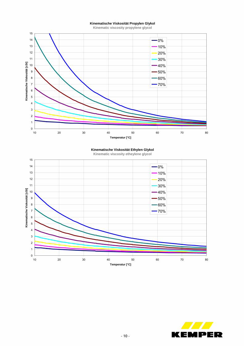
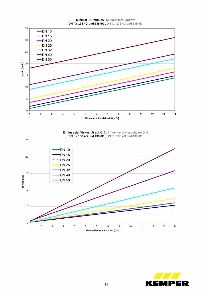
8.1 Diagramme für Qo und Qmin
Aus den folgenden Diagrammen müssen zuerst folgende Punkte bestimmt werden: - Viskosität des Glykolgemisches - Q0 der Kennlinienformel - Qmin 8.1 Diagrams for Q
oo and Q
mimin
The following points first need to be identified from the diagrams below: - Viscosity of the glycol mixture - Q
00 of the characteristic formula - Q min
Figur 138 6G, DN 15 - DN 50,´Control-plus 4 – 20 mA´,
Q = k • (I – 4mA) - Q0 Sensor
k [-] Q0 [l/min] Qmin [l/min]
10 0,938 0,45 - 0,45 - 0,1
15 2,000 0,40 - 0,40 + 0,8
20 3,125 0,45 - 0,45 + 2,5
25 5,323 0,55 - 0,55 + 4,0
32 9,375 0,80 - 0,80 + 8,0
40 11,738 1,17 - 1,17 + 10,0
50 19,769 1,70 - 1,70 + 17
- 10 -
Kinematische Viskosität Propylen GlykolKinematic viscosity propylene glycol
0
1
2
3
4
5
6
7
8
9
10
11
12
13
14
15
10 20 30 40 50 60 70 80
Temperatur [°C]
Kin
emat
isch
e V
isko
sitä
t [c
St]
0%
10%
20%
30%
40%
50%
60%
70%
Kinematische Viskosität Ethylen GlykolKinematic viscosity etheylene glycol
0
1
2
3
4
5
6
7
8
9
10
11
12
13
14
15
10 20 30 40 50 60 70 80
Temperatur [°C]
Kin
emat
isch
e V
isko
sitä
t [c
St]
0%
10%
20%
30%
40%
50%
60%
70%
- 11 -
Minimal Durchfluss , minimal throughflowDN für 138 4G und 138 6G , DN for 138 4G and 138 6G
0
5
10
15
20
25
30
35
1 2 3 4 5 6 7 8 9 10 11 12 13 14
Kinematische Viskosität [cSt]
Q_m
in [
l/min
]
DN 10DN 15DN 20DN 25DN 32DN 40DN 50
Einfluss der Viskosität auf Q_0 , Influence of viscosity on Q_0 DN für 138 4G und 138 6G , DN for 138 4G and 138 6G
0
5
10
15
20
25
1 2 3 4 5 6 7 8 9 10 11 12 13 14
Kinematische Viskosität [cSt]
Q_0
[l/m
in]
DN 10
DN 15
DN 20
DN 25
DN 32
DN 40
DN 50
- 12 -
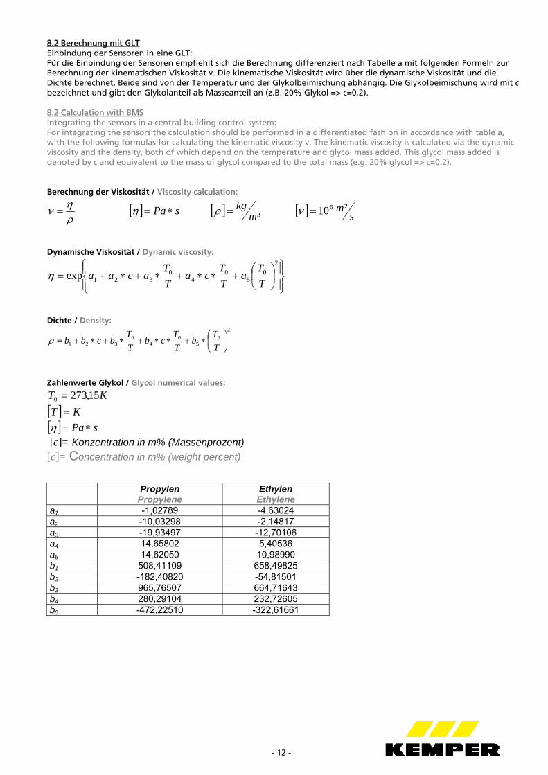
8.2 Berechnung mit GLT Einbindung der Sensoren in eine GLT: Für die Einbindung der Sensoren empfiehlt sich die Berechnung differenziert nach Tabelle a mit folgenden Formeln zur Berechnung der kinematischen Viskosität ν. Die kinematische Viskosität wird über die dynamische Viskosität und die Dichte berechnet. Beide sind von der Temperatur und der Glykolbeimischung abhängig. Die Glykolbeimischung wird mit c bezeichnet und gibt den Glykolanteil als Masseanteil an (z.B. 20% Glykol => c=0,2). 8.2 Calculation with BMS Integrating the sensors in a central building control system: For integrating the sensors the calculation should be performed in a differentiated fashion in accordance with table a, with the following formulas for calculating the kinematic viscosity ν. The kinematic viscosity is calculated via the dynamic viscosity and the density, both of which depend on the temperature and glycol mass added. This glycol mass added is denoted by c and equivalent to the mass of glycol compared to the total mass (e.g. 20% glycol => c=0.2). Berechnung der Viskosität / Viscosity calculation:
sPa ³m
kg sm²106
Dynamische Viskosität / Dynamic viscosity:
2
05
04
0321exp
T
Ta
T
Tca
T
Tacaa
Dichte / Density:
2
05
04
0321
T
Tb
T
Tcb
T
Tbcbb
Zahlenwerte Glykol / Glycol numerical values:
KT 15,2730 KT sPa
[c]= Konzentration in m% (Massenprozent)
[c]= Concentration in m% (weight percent)
Propylen
Propylene Ethylen Ethylene
a1 -1,02789 -4,63024 a2 -10,03298 -2,14817 a3 -19,93497 -12,70106 a4 14,65802 5,40536 a5 14,62050 10,98990 b1 508,41109 658,49825 b2 -182,40820 -54,81501 b3 965,76507 664,71643 b4 280,29104 232,72605 b5 -472,22510 -322,61661
- 13 -
Aus den nun bekannten Größen dynamische Viskosität η und Dichte ρ kann die kinematische Viskosität
mit berechnet werden.
Zusätzlich kann neben dem Volumenstrom Q auch der Massenstrom
m über die Beziehung Qm
berechnet
werden. Über die Beziehungen in Tabelle a und der Kenntnis der Dichte ρ – wie eben berechnet – ist der Massenstrom indirekt bekannt. The kinematic viscosity v can now be calculated from the known values for the dynamic viscosity η and density ρ using the formula
Besides the volume flow rate Q , the mass flow rate
m can also be calculated via the relation Qm
. The mass flow
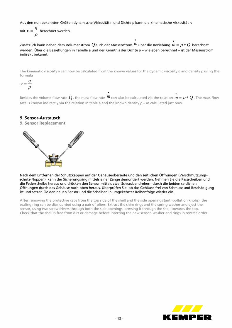
rate is known indirectly via the relation in table a and the known density ρ – as calculated just now. 9. Sensor-Austausch 9. Sensor Replacement
Nach dem Entfernen der Schutzkappen auf der Gehäuseoberseite und den seitlichen Öffnungen (Verschmutzungs- schutz-Noppen), kann der Sicherungsring mittels einer Zange demontiert werden. Nehmen Sie die Passscheiben und die Federscheibe heraus und drücken den Sensor mittels zwei Schraubendrehern durch die beiden seitlichen Öffnungen durch das Gehäuse nach oben heraus. Überprüfen Sie, ob das Gehäuse frei von Schmutz und Beschädigung ist und setzen Sie den neuen Sensor und die Scheiben in umgekehrter Reihenfolge wieder ein. After removing the protective caps from the top side of the shell and the side openings (anti-pollution knobs), the sealing ring can be dismounted using a pair of pliers. Extract the shim rings and the spring washer and eject the sensor, using two screwdrivers through both the side openings, pressing it through the shell towards the top. Check that the shell is free from dirt or damage before inserting the new sensor, washer and rings in reverse order.
- 14 -
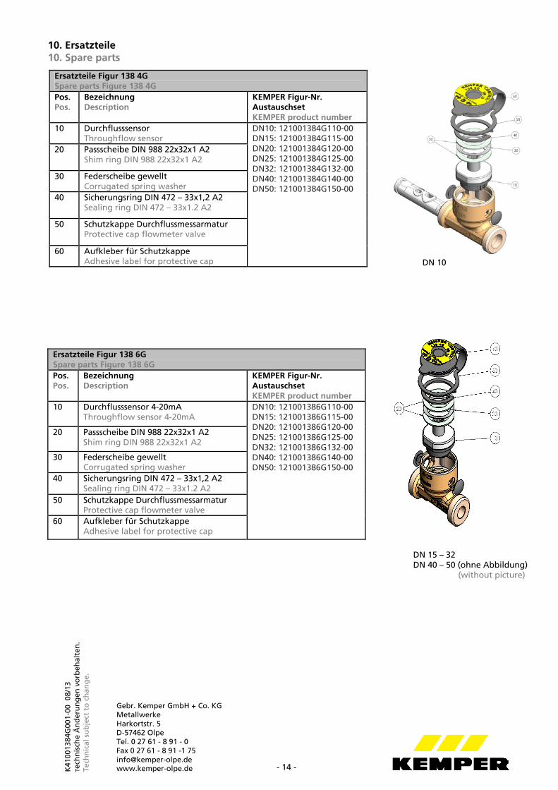
10. Ersatzteile 10. Spare parts
Ersatzteile Figur 138 6G Spare parts Figure 138 6G Pos. Pos.
Bezeichnung Description
KEMPER Figur-Nr. Austauschset KEMPER product number
10 Durchflusssensor 4-20mA Throughflow sensor 4-20mA
DN10: 121001386G110-00 DN15: 121001386G115-00 DN20: 121001386G120-00 DN25: 121001386G125-00 DN32: 121001386G132-00 DN40: 121001386G140-00 DN50: 121001386G150-00
20 Passscheibe DIN 988 22x32x1 A2 Shim ring DIN 988 22x32x1 A2
30 Federscheibe gewellt Corrugated spring washer
40 Sicherungsring DIN 472 – 33x1,2 A2 Sealing ring DIN 472 – 33x1.2 A2
50 Schutzkappe Durchflussmessarmatur Protective cap flowmeter valve
60 Aufkleber für Schutzkappe Adhesive label for protective cap
DN 15 – 32 DN 40 – 50 (ohne Abbildung) (without picture)
Ersatzteile Figur 138 4G Spare parts Figure 138 4G Pos. Pos.
Bezeichnung Description
KEMPER Figur-Nr. Austauschset KEMPER product number
10 Durchflusssensor Throughflow sensor
DN10: 121001384G110-00 DN15: 121001384G115-00 DN20: 121001384G120-00 DN25: 121001384G125-00 DN32: 121001384G132-00 DN40: 121001384G140-00 DN50: 121001384G150-00
20 Passscheibe DIN 988 22x32x1 A2 Shim ring DIN 988 22x32x1 A2
30 Federscheibe gewellt Corrugated spring washer
40 Sicherungsring DIN 472 – 33x1,2 A2 Sealing ring DIN 472 – 33x1.2 A2
50 Schutzkappe Durchflussmessarmatur Protective cap flowmeter valve
60 Aufkleber für Schutzkappe Adhesive label for protective cap DN 10
K41
0013
84G
001-
00 0
8/13
Te
chn
isch
e Ä
nd
eru
ng
en v
orb
ehal
ten
. Te
chn
ical
su
bje
ct t
o c
han
ge.
Gebr. Kemper GmbH + Co. KG Metallwerke Harkortstr. 5 D-57462 Olpe Tel. 0 27 61 - 8 91 - 0 Fax 0 27 61 - 8 91 -1 75 [email protected] www.kemper-olpe.de