Embed Size (px)
Citation preview
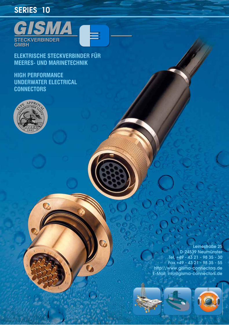
ELEKTRISCHE STECKVERBINDER FÜRMEERES- UND MARINETECHNIK
HIGH PERFORMANCEUNDERWATER ELECTRICALCONNECTORS
Leinestraße 25D-24539 Neumünster
Tel. +49 - 43 21 - 98 35 - 30 Fax +49 - 43 21 - 98 35 - 55
http://www.gisma-connectors.deE-Mail: [email protected]
SERIES 10
GISMA SERIES 10 / Rev.-Index: 05/2014 3
PLUG
Size Contact arrangement Ø A Ø B C D E F SW G
1 4 x 1 30 16.9 27 33.5 45,5 55 26
2 3 x 1.5 ; 7 x 1 37 19.9 27 33.5 44 56 32
3 7 x 1.5 ; 12 x 1 39 24 27 33.5 45 56 34
4 12 x 1.5 ; 19 x 1 46.5 28.5 27 33.5 45 55 41
5 24 x 1.5 ; 37 x 1 58 41 30 37.2 50,5 55 54
6 37 x 1.5 ; 61 x 1 67 48 31 37 50 56 62
7 4 x 10 110 77 66.5 78 138 153 100
71 4 x 10 120 105 104.5 154 184 223 110
ENDBELL
Size Contact arrangementstandard endbell large cable Ø endbell
max. cable Ø A 1max. cable Ø A B ca. C ca. D ca.
1 4 x 1 14 28 98 142 16 (see dimensions size 3)
2 3 x 1.5 ; 7 x 1 14 28 98 142 16 (see dimensions size 3)
3 7 x 1.5 ; 12 x 1 16 34 109 160 22 (see dimensions size 4)
4 12 x 1.5 ; 19 x 1 20 42 107 157 31 (see dimensions size 5)
5 24 x 1.5 ; 37 x 1 31 52 113 219 42 (dimensions on request)
6 37 x 1.5 ; 61 x 1 31 52 113 207 52 (dimensions on request)
7 4 x 10 57 83 229 342 ---
71 4 x 10 57 83 128 433 ---
12
NEW: 120° AND 90° MOULDING ENDBELL WITH RUBBER BOOT
Size Ø A B Ø C SW D E F Ø G max. Ø H J K
1 30 27 35 26 --- --- 28 13 106 158
2 37 27 41 32 --- --- 28 13 99 160
3 39 27 42 34 156 162 34 15 114 195
4 46,5 27 49 41 --- --- 47 25 119 196
5 58 30 59 54 215 203 52 31 172 244
6 67 31 70 62 --- --- 52 42 198 280
7 110 66,5 --- 100 --- --- 83 --- --- ---
13
A
SW D
J
C
90°
K
B
HG
A
120
°
SW D
F
B
E
C
G
H
NEW: 120° AND 90° MOULDING ENDBELL WITH RUBBER BOOT
Size Ø A B Ø C SW D E F Ø G max. Ø H J K
1 30 27 35 26 --- --- 28 13 106 158
2 37 27 41 32 --- --- 28 13 99 160
3 39 27 42 34 156 162 34 15 114 195
4 46,5 27 49 41 --- --- 47 25 119 196
5 58 30 59 54 215 203 52 31 172 244
6 67 31 70 62 --- --- 52 42 198 280
7 110 66,5 --- 100 --- --- 83 --- --- ---
13
13GISMA SERIES 10 / Rev.-Index: 01/2013
CONTENTS PAGE
COMPANY PROFILE....................................................................................................................................................4SHELL STYLES.............................................................................................................................................................5DESIGN.........................................................................................................................................................................6MECHANICAL FEATURES...........................................................................................................................................7ELECTRICAL FEATURES............................................................................................................................................7REFERENCE SYSTEM.................................................................................................................................................8SHELL SIZE / CONTACT LAYOUTS............................................................................................................................9RECEPTACLE.............................................................................................................................................................10FLANGE RECEPTACLE.............................................................................................................................................10THROUGH BULKHEAD RECEPTACLE.....................................................................................................................11CABLE CONNECTING RECEPTACLE......................................................................................................................11PLUG...........................................................................................................................................................................12ENDBELL....................................................................................................................................................................12NEW: 120° AND 90° MOULDING ENDBELL WITH RUBBER BOOT........................................................................13SEALING CAP.............................................................................................................................................................14KEYWAYS...................................................................................................................................................................15SPACER......................................................................................................................................................................15CONTACT ARRANGEMENTS (NUMBERING SYSTEM, PLUG BACKVIEW)..........................................................16CONTACT ARRANGEMENTS (NUMBERING SYSTEM, RECEPTACLE BACKVIEW)...........................................17
This catalogue supersedes all previous editions. This catalogue is available as PDF file as well. GISMA reserves the right to modify products because of technical improvements and development without prior notice. Dimensions are given for information purposes only and must be confirmed by GISMA.
ATTENTION: Catalogue data apply to standard connectors only. Technical data of special designs (p/n LV XXX) may differ. Upon request, technical data sheets are available.
3
3GISMA SERIES 10 / Rev.-Index: 01/2013
GISMA SERIES 10 / Rev.-Index: 05/20144
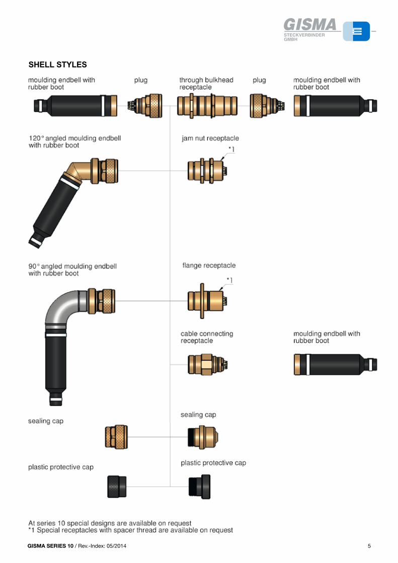
SHELL STYLES
5
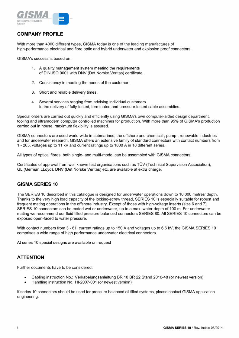
COMPANY PROFILE
With more than 4000 different types, GISMA today is one of the leading manufactures of high-performance electrical and fibre optic and hybrid underwater and explosion proof connectors.
GISMA's success is based on:
1. A quality management system meeting the requirements of DIN ISO 9001 with DNV (Det Norske Veritas) certificate.
2. Consistency in meeting the needs of the customer.
3. Short and reliable delivery times.
4. Several services ranging from advising individual customers to the delivery of fully-tested, terminated and pressure tested cable assemblies.
Special orders are carried out quickly and efficiently using GISMA's own computer-aided design department, tooling and ultramodern computer controlled machines for production. With more than 95% of GISMA's production carried out in house, maximum flexibility is assured.
GISMA connectors are used world-wide in submarines, the offshore and chemical-, pump-, renewable industries and for underwater research. GISMA offers an extensive family of standard connectors with contact numbers from 1 - 265, voltages up to 11 kV and current ratings up to 1000 A in 18 different series.
All types of optical fibres, both single- and multi-mode, can be assembled with GISMA connectors.
Certificates of approval from well known test organisations such as TÜV (Technical Supervision Association), GL (German LLoyd), DNV (Det Norske Veritas) etc. are available at extra charge.
GISMA SERIES 10
The SERIES 10 described in this catalogue is designed for underwater operations down to 10.000 metres' depth. Thanks to the very high load capacity of the locking-screw thread, SERIES 10 is especially suitable for robust and frequent mating operations in the offshore industry. Except of those with high-voltage inserts (size 6 and 7), SERIES 10 connectors can be mated wet or underwater, up to a max. water-depth of 100 m. For underwater mating we recommend our fluid filled pressure balanced connectors SERIES 80. All SERIES 10 connectors can be exposed open-faced to water pressure.
With contact numbers from 3 - 61, current ratings up to 150 A and voltages up to 6.6 kV, the GISMA SERIES 10 comprises a wide range of high performance underwater electrical connectors.
At series 10 special designs are available on request
ATTENTION
Further documents have to be considered:
• Cabling instruction No.: Verkabelungsanleitung BR 10 BR 22 Stand 2010-48 (or newest version)• Handling instruction No.:HI-2007-001 (or newest version)
If series 10 connectors should be used for pressure balanced oil filled systems, please contact GISMA application engineering.
44 GISMA SERIES 10 / Rev.-Index: 01/2013
SHELL STYLES
5
COMPANY PROFILE
With more than 4000 different types, GISMA today is one of the leading manufactures of high-performance electrical and fibre optic and hybrid underwater and explosion proof connectors.
GISMA's success is based on:
1. A quality management system meeting the requirements of DIN ISO 9001 with DNV (Det Norske Veritas) certificate.
2. Consistency in meeting the needs of the customer.
3. Short and reliable delivery times.
4. Several services ranging from advising individual customers to the delivery of fully-tested, terminated and pressure tested cable assemblies.
Special orders are carried out quickly and efficiently using GISMA's own computer-aided design department, tooling and ultramodern computer controlled machines for production. With more than 95% of GISMA's production carried out in house, maximum flexibility is assured.
GISMA connectors are used world-wide in submarines, the offshore and chemical-, pump-, renewable industries and for underwater research. GISMA offers an extensive family of standard connectors with contact numbers from 1 - 265, voltages up to 11 kV and current ratings up to 1000 A in 18 different series.
All types of optical fibres, both single- and multi-mode, can be assembled with GISMA connectors.
Certificates of approval from well known test organisations such as TÜV (Technical Supervision Association), GL (German LLoyd), DNV (Det Norske Veritas) etc. are available at extra charge.
GISMA SERIES 10
The SERIES 10 described in this catalogue is designed for underwater operations down to 10.000 metres' depth. Thanks to the very high load capacity of the locking-screw thread, SERIES 10 is especially suitable for robust and frequent mating operations in the offshore industry. Except of those with high-voltage inserts (size 6 and 7), SERIES 10 connectors can be mated wet or underwater, up to a max. water-depth of 100 m. For underwater mating we recommend our fluid filled pressure balanced connectors SERIES 80. All SERIES 10 connectors can be exposed open-faced to water pressure.
With contact numbers from 3 - 61, current ratings up to 150 A and voltages up to 6.6 kV, the GISMA SERIES 10 comprises a wide range of high performance underwater electrical connectors.
At series 10 special designs are available on request
ATTENTION
Further documents have to be considered:
• Cabling instruction No.: Verkabelungsanleitung BR 10 BR 22 Stand 2010-48 (or newest version)• Handling instruction No.:HI-2007-001 (or newest version)
If series 10 connectors should be used for pressure balanced oil filled systems, please contact GISMA application engineering.
44 GISMA SERIES 10 / Rev.-Index: 01/2013
GISMA SERIES 10 / Rev.-Index: 05/2014 5
PLUG
Size Contact arrangement Ø A Ø B C D E F SW G
1 4 x 1 30 16.9 27 33.5 45,5 55 26
2 3 x 1.5 ; 7 x 1 37 19.9 27 33.5 44 56 32
3 7 x 1.5 ; 12 x 1 39 24 27 33.5 45 56 34
4 12 x 1.5 ; 19 x 1 46.5 28.5 27 33.5 45 55 41
5 24 x 1.5 ; 37 x 1 58 41 30 37.2 50,5 55 54
6 37 x 1.5 ; 61 x 1 67 48 31 37 50 56 62
7 4 x 10 110 77 66.5 78 138 153 100
71 4 x 10 120 105 104.5 154 184 223 110
ENDBELL
Size Contact arrangementstandard endbell large cable Ø endbell
max. cable Ø A 1max. cable Ø A B ca. C ca. D ca.
1 4 x 1 14 28 98 142 16 (see dimensions size 3)
2 3 x 1.5 ; 7 x 1 14 28 98 142 16 (see dimensions size 3)
3 7 x 1.5 ; 12 x 1 16 34 109 160 22 (see dimensions size 4)
4 12 x 1.5 ; 19 x 1 20 42 107 157 31 (see dimensions size 5)
5 24 x 1.5 ; 37 x 1 31 52 113 219 42 (dimensions on request)
6 37 x 1.5 ; 61 x 1 31 52 113 207 52 (dimensions on request)
7 4 x 10 57 83 229 342 ---
71 4 x 10 57 83 128 433 ---
12
NEW: 120° AND 90° MOULDING ENDBELL WITH RUBBER BOOT
Size Ø A B Ø C SW D E F Ø G max. Ø H J K
1 30 27 35 26 --- --- 28 13 106 158
2 37 27 41 32 --- --- 28 13 99 160
3 39 27 42 34 156 162 34 15 114 195
4 46,5 27 49 41 --- --- 47 25 119 196
5 58 30 59 54 215 203 52 31 172 244
6 67 31 70 62 --- --- 52 42 198 280
7 110 66,5 --- 100 --- --- 83 --- --- ---
13
A
SW D
J
C
90°
K
B
HG
A
120
°
SW D
F
B
E
C
G
H
NEW: 120° AND 90° MOULDING ENDBELL WITH RUBBER BOOT
Size Ø A B Ø C SW D E F Ø G max. Ø H J K
1 30 27 35 26 --- --- 28 13 106 158
2 37 27 41 32 --- --- 28 13 99 160
3 39 27 42 34 156 162 34 15 114 195
4 46,5 27 49 41 --- --- 47 25 119 196
5 58 30 59 54 215 203 52 31 172 244
6 67 31 70 62 --- --- 52 42 198 280
7 110 66,5 --- 100 --- --- 83 --- --- ---
13
13GISMA SERIES 10 / Rev.-Index: 01/2013
SHELL STYLES
5
COMPANY PROFILE
With more than 4000 different types, GISMA today is one of the leading manufactures of high-performance electrical and fibre optic and hybrid underwater and explosion proof connectors.
GISMA's success is based on:
1. A quality management system meeting the requirements of DIN ISO 9001 with DNV (Det Norske Veritas) certificate.
2. Consistency in meeting the needs of the customer.
3. Short and reliable delivery times.
4. Several services ranging from advising individual customers to the delivery of fully-tested, terminated and pressure tested cable assemblies.
Special orders are carried out quickly and efficiently using GISMA's own computer-aided design department, tooling and ultramodern computer controlled machines for production. With more than 95% of GISMA's production carried out in house, maximum flexibility is assured.
GISMA connectors are used world-wide in submarines, the offshore and chemical-, pump-, renewable industries and for underwater research. GISMA offers an extensive family of standard connectors with contact numbers from 1 - 265, voltages up to 11 kV and current ratings up to 1000 A in 18 different series.
All types of optical fibres, both single- and multi-mode, can be assembled with GISMA connectors.
Certificates of approval from well known test organisations such as TÜV (Technical Supervision Association), GL (German LLoyd), DNV (Det Norske Veritas) etc. are available at extra charge.
GISMA SERIES 10
The SERIES 10 described in this catalogue is designed for underwater operations down to 10.000 metres' depth. Thanks to the very high load capacity of the locking-screw thread, SERIES 10 is especially suitable for robust and frequent mating operations in the offshore industry. Except of those with high-voltage inserts (size 6 and 7), SERIES 10 connectors can be mated wet or underwater, up to a max. water-depth of 100 m. For underwater mating we recommend our fluid filled pressure balanced connectors SERIES 80. All SERIES 10 connectors can be exposed open-faced to water pressure.
With contact numbers from 3 - 61, current ratings up to 150 A and voltages up to 6.6 kV, the GISMA SERIES 10 comprises a wide range of high performance underwater electrical connectors.
At series 10 special designs are available on request
ATTENTION
Further documents have to be considered:
• Cabling instruction No.: Verkabelungsanleitung BR 10 BR 22 Stand 2010-48 (or newest version)• Handling instruction No.:HI-2007-001 (or newest version)
If series 10 connectors should be used for pressure balanced oil filled systems, please contact GISMA application engineering.
4 5GISMA SERIES 10 / Rev.-Index: 01/2013
GISMA SERIES 10 / Rev.-Index: 05/20146
SHELL STYLES
5
COMPANY PROFILE
With more than 4000 different types, GISMA today is one of the leading manufactures of high-performance electrical and fibre optic and hybrid underwater and explosion proof connectors.
GISMA's success is based on:
1. A quality management system meeting the requirements of DIN ISO 9001 with DNV (Det Norske Veritas) certificate.
2. Consistency in meeting the needs of the customer.
3. Short and reliable delivery times.
4. Several services ranging from advising individual customers to the delivery of fully-tested, terminated and pressure tested cable assemblies.
Special orders are carried out quickly and efficiently using GISMA's own computer-aided design department, tooling and ultramodern computer controlled machines for production. With more than 95% of GISMA's production carried out in house, maximum flexibility is assured.
GISMA connectors are used world-wide in submarines, the offshore and chemical-, pump-, renewable industries and for underwater research. GISMA offers an extensive family of standard connectors with contact numbers from 1 - 265, voltages up to 11 kV and current ratings up to 1000 A in 18 different series.
All types of optical fibres, both single- and multi-mode, can be assembled with GISMA connectors.
Certificates of approval from well known test organisations such as TÜV (Technical Supervision Association), GL (German LLoyd), DNV (Det Norske Veritas) etc. are available at extra charge.
GISMA SERIES 10
The SERIES 10 described in this catalogue is designed for underwater operations down to 10.000 metres' depth. Thanks to the very high load capacity of the locking-screw thread, SERIES 10 is especially suitable for robust and frequent mating operations in the offshore industry. Except of those with high-voltage inserts (size 6 and 7), SERIES 10 connectors can be mated wet or underwater, up to a max. water-depth of 100 m. For underwater mating we recommend our fluid filled pressure balanced connectors SERIES 80. All SERIES 10 connectors can be exposed open-faced to water pressure.
With contact numbers from 3 - 61, current ratings up to 150 A and voltages up to 6.6 kV, the GISMA SERIES 10 comprises a wide range of high performance underwater electrical connectors.
At series 10 special designs are available on request
ATTENTION
Further documents have to be considered:
• Cabling instruction No.: Verkabelungsanleitung BR 10 BR 22 Stand 2010-48 (or newest version)• Handling instruction No.:HI-2007-001 (or newest version)
If series 10 connectors should be used for pressure balanced oil filled systems, please contact GISMA application engineering.
44 GISMA SERIES 10 / Rev.-Index: 01/20136
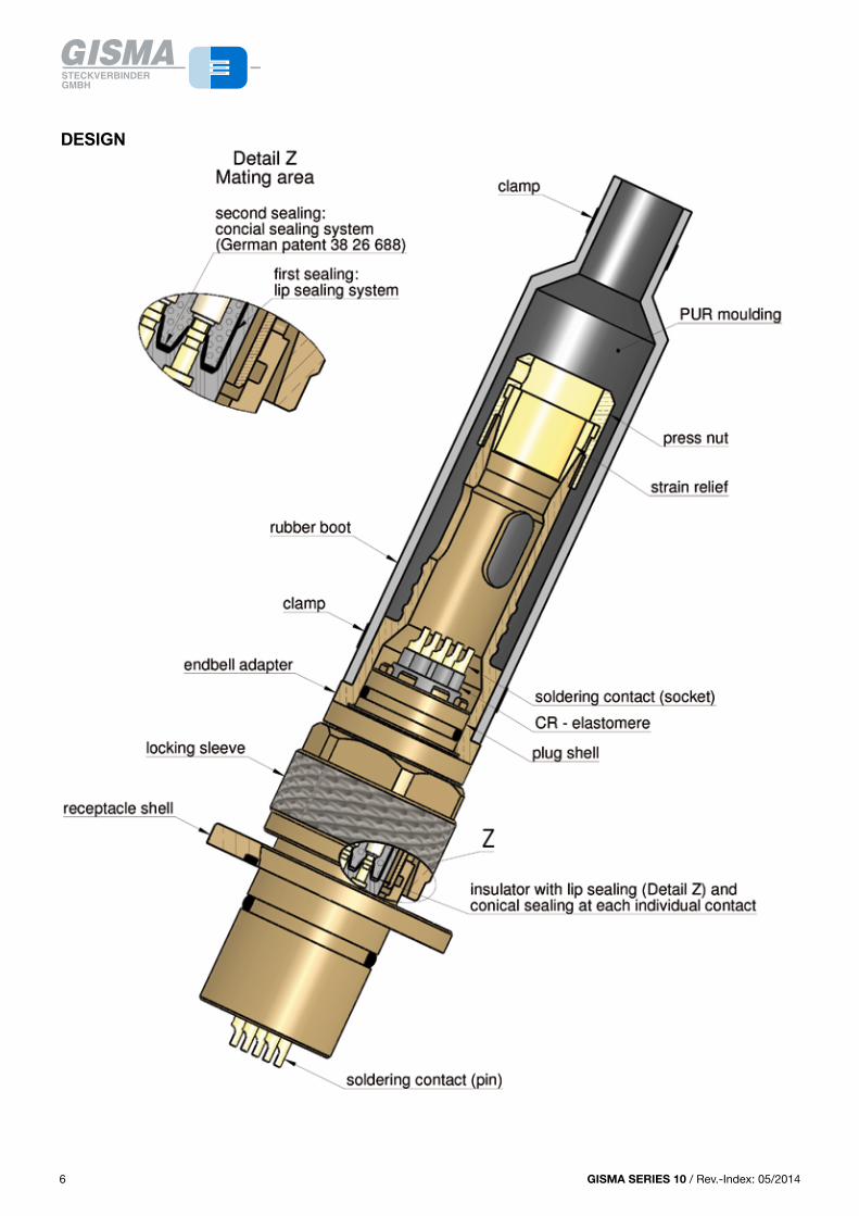
DESIGN
GISMA SERIES 10 / Rev.-Index: 05/2014 7
PLUG
Size Contact arrangement Ø A Ø B C D E F SW G
1 4 x 1 30 16.9 27 33.5 45,5 55 26
2 3 x 1.5 ; 7 x 1 37 19.9 27 33.5 44 56 32
3 7 x 1.5 ; 12 x 1 39 24 27 33.5 45 56 34
4 12 x 1.5 ; 19 x 1 46.5 28.5 27 33.5 45 55 41
5 24 x 1.5 ; 37 x 1 58 41 30 37.2 50,5 55 54
6 37 x 1.5 ; 61 x 1 67 48 31 37 50 56 62
7 4 x 10 110 77 66.5 78 138 153 100
71 4 x 10 120 105 104.5 154 184 223 110
ENDBELL
Size Contact arrangementstandard endbell large cable Ø endbell
max. cable Ø A 1max. cable Ø A B ca. C ca. D ca.
1 4 x 1 14 28 98 142 16 (see dimensions size 3)
2 3 x 1.5 ; 7 x 1 14 28 98 142 16 (see dimensions size 3)
3 7 x 1.5 ; 12 x 1 16 34 109 160 22 (see dimensions size 4)
4 12 x 1.5 ; 19 x 1 20 42 107 157 31 (see dimensions size 5)
5 24 x 1.5 ; 37 x 1 31 52 113 219 42 (dimensions on request)
6 37 x 1.5 ; 61 x 1 31 52 113 207 52 (dimensions on request)
7 4 x 10 57 83 229 342 ---
71 4 x 10 57 83 128 433 ---
12
NEW: 120° AND 90° MOULDING ENDBELL WITH RUBBER BOOT
Size Ø A B Ø C SW D E F Ø G max. Ø H J K
1 30 27 35 26 --- --- 28 13 106 158
2 37 27 41 32 --- --- 28 13 99 160
3 39 27 42 34 156 162 34 15 114 195
4 46,5 27 49 41 --- --- 47 25 119 196
5 58 30 59 54 215 203 52 31 172 244
6 67 31 70 62 --- --- 52 42 198 280
7 110 66,5 --- 100 --- --- 83 --- --- ---
13
A
SW D
J
C
90°
K
B
HG
A
120
°
SW D
F
B
E
C
G
H
NEW: 120° AND 90° MOULDING ENDBELL WITH RUBBER BOOT
Size Ø A B Ø C SW D E F Ø G max. Ø H J K
1 30 27 35 26 --- --- 28 13 106 158
2 37 27 41 32 --- --- 28 13 99 160
3 39 27 42 34 156 162 34 15 114 195
4 46,5 27 49 41 --- --- 47 25 119 196
5 58 30 59 54 215 203 52 31 172 244
6 67 31 70 62 --- --- 52 42 198 280
7 110 66,5 --- 100 --- --- 83 --- --- ---
13
13GISMA SERIES 10 / Rev.-Index: 01/2013
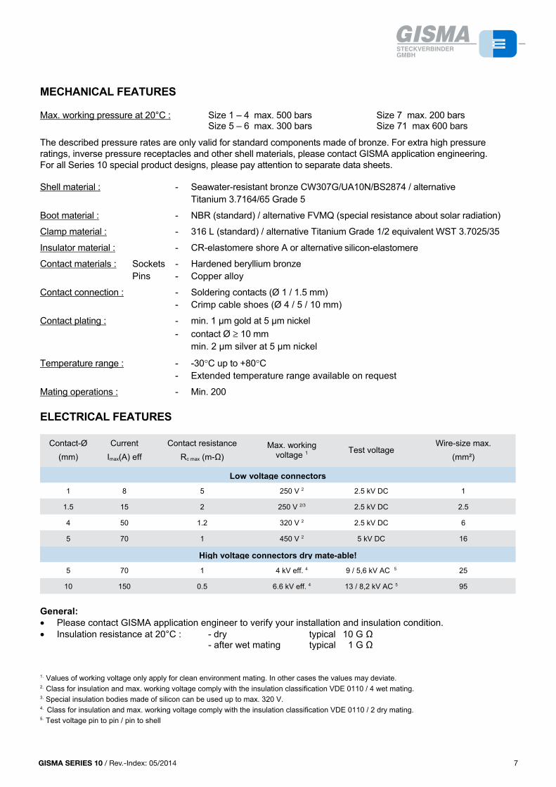
MECHANICAL FEATURES
Max. working pressure at 20°C : Size 1 – 4 max. 500 bars Size 7 max. 200 barsSize 5 – 6 max. 300 bars Size 71 max 600 bars
The described pressure rates are only valid for standard components made of bronze. For extra high pressure ratings, inverse pressure receptacles and other shell materials, please contact GISMA application engineering.For all Series 10 special product designs, please pay attention to separate data sheets.
Shell material : - Seawater-resistant bronze CW307G/UA10N/BS2874 / alternative Titanium 3.7164/65 Grade 5
Boot material : - NBR (standard) / alternative FVMQ (special resistance about solar radiation)
Clamp material : - 316 L (standard) / alternative Titanium Grade 1/2 equivalent WST 3.7025/35
Insulator material : - CR-elastomere shore A or alternative Silicon-elastomere
Contact materials : Sockets - Hardened beryllium bronzePins - Copper alloy
Contact connection : - Soldering contacts (Ø 1 / 1.5 mm)- Crimp cable shoes (Ø 4 / 5 / 10 mm)
Contact plating : - min. 1 µm gold at 5 µm nickel- contact Ø ≥ 10 mm
min. 2 µm silver at 5 µm nickel
Temperature range : - -30°C up to +80°C- Extended temperature range available on request
Mating operations : - Min. 200
ELECTRICAL FEATURES
Contact-Ø(mm)
CurrentImax(A) eff
Contact resistanceRc max (m-Ω)
Max. working voltage 1 Test voltage
Wire-size max.(mm²)
Low voltage connectors
1 8 5 250 V 2 2.5 kV DC 1
1.5 15 2 250 V 2/3 2.5 kV DC 2.5
4 50 1.2 320 V 2 2.5 kV DC 6
5 70 1 450 V 2 5 kV DC 16
High voltage connectors dry mate-able!
5 70 1 4 kV eff. 4 9 / 5,6 kV AC 5 25
10 150 0.5 6.6 kV eff. 4 13 / 8,2 kV AC 5 95
General:• Please contact GISMA application engineer to verify your installation and insulation condition.• Insulation resistance at 20°C : - dry typical 10 G Ω
- after wet mating typical 1 G Ω
1. Values of working voltage only apply for clean environment mating. In other cases the values may deviate.2. Class for insulation and max. working voltage comply with the insulation classification VDE 0110 / 4 wet mating.3. Special insulation bodies made of silicon can be used up to max. 320 V.4. Class for insulation and max. working voltage comply with the insulation classification VDE 0110 / 2 dry mating.5. Test voltage pin to pin / pin to shell
7
DESIGN
6 7GISMA SERIES 10 / Rev.-Index: 01/2013 7
MECHANICAL FEATURES
Max. working pressure at 20°C : Size 1 – 4 max. 500 bars Size 7 max. 200 barsSize 5 – 6 max. 300 bars Size 71 max 600 bars
The described pressure rates are only valid for standard components made of bronze. For extra high pressure ratings, inverse pressure receptacles and other shell materials, please contact GISMA application engineering.For all Series 10 special product designs, please pay attention to separate data sheets.
Shell material : - Seawater-resistant bronze CW307G/UA10N/BS2874 / alternative Titanium 3.7164/65 Grade 5
Boot material : - NBR (standard) / alternative FVMQ (special resistance about solar radiation)
Clamp material : - 316 L (standard) / alternative Titanium Grade 1/2 equivalent WST 3.7025/35
Insulator material : - CR-elastomere shore A or alternative silicon-elastomere
Contact materials : Sockets - Hardened beryllium bronzePins - Copper alloy
Contact connection : - Soldering contacts (Ø 1 / 1.5 mm)- Crimp cable shoes (Ø 4 / 5 / 10 mm)
Contact plating : - min. 1 µm gold at 5 µm nickel- contact Ø ≥ 10 mm
min. 2 µm silver at 5 µm nickel
Temperature range : - -30°C up to +80°C- Extended temperature range available on request
Mating operations : - Min. 200
ELECTRICAL FEATURES
Contact-Ø(mm)
CurrentImax(A) eff
Contact resistanceRc max (m-Ω)
Max. working voltage 1 Test voltage
Wire-size max.(mm²)
Low voltage connectors
1 8 5 250 V 2 2.5 kV DC 1
1.5 15 2 250 V 2/3 2.5 kV DC 2.5
4 50 1.2 320 V 2 2.5 kV DC 6
5 70 1 450 V 2 5 kV DC 16
High voltage connectors dry mate-able!
5 70 1 4 kV eff. 4 9 / 5.6 kV AC 5 25
10 150 0.5 6.6 kV eff. 4 13 / 8.2 kV AC 5 95
General:• Please contact GISMA application engineer to verify your installation and insulation condition.• Insulation resistance at 20°C : - dry typical 10 G Ω
- after wet mating typical 1 G Ω
1. Values of working voltage only apply for clean environment mating. In other cases the values may deviate.2. Class for insulation and max. working voltage comply with the insulation classification VDE 0110 / 4 wet mating.3. Special insulation bodies made of silicon can be used up to max. 320 V.4. Class for insulation and max. working voltage comply with the insulation classification VDE 0110 / 2 dry mating.5. Test voltage pin to pin / pin to shell
GISMA SERIES 10 / Rev.-Index: 05/20148
SHELL STYLES
5
COMPANY PROFILE
With more than 4000 different types, GISMA today is one of the leading manufactures of high-performance electrical and fibre optic and hybrid underwater and explosion proof connectors.
GISMA's success is based on:
1. A quality management system meeting the requirements of DIN ISO 9001 with DNV (Det Norske Veritas) certificate.
2. Consistency in meeting the needs of the customer.
3. Short and reliable delivery times.
4. Several services ranging from advising individual customers to the delivery of fully-tested, terminated and pressure tested cable assemblies.
Special orders are carried out quickly and efficiently using GISMA's own computer-aided design department, tooling and ultramodern computer controlled machines for production. With more than 95% of GISMA's production carried out in house, maximum flexibility is assured.
GISMA connectors are used world-wide in submarines, the offshore and chemical-, pump-, renewable industries and for underwater research. GISMA offers an extensive family of standard connectors with contact numbers from 1 - 265, voltages up to 11 kV and current ratings up to 1000 A in 18 different series.
All types of optical fibres, both single- and multi-mode, can be assembled with GISMA connectors.
Certificates of approval from well known test organisations such as TÜV (Technical Supervision Association), GL (German LLoyd), DNV (Det Norske Veritas) etc. are available at extra charge.
GISMA SERIES 10
The SERIES 10 described in this catalogue is designed for underwater operations down to 10.000 metres' depth. Thanks to the very high load capacity of the locking-screw thread, SERIES 10 is especially suitable for robust and frequent mating operations in the offshore industry. Except of those with high-voltage inserts (size 6 and 7), SERIES 10 connectors can be mated wet or underwater, up to a max. water-depth of 100 m. For underwater mating we recommend our fluid filled pressure balanced connectors SERIES 80. All SERIES 10 connectors can be exposed open-faced to water pressure.
With contact numbers from 3 - 61, current ratings up to 150 A and voltages up to 6.6 kV, the GISMA SERIES 10 comprises a wide range of high performance underwater electrical connectors.
At series 10 special designs are available on request
ATTENTION
Further documents have to be considered:
• Cabling instruction No.: Verkabelungsanleitung BR 10 BR 22 Stand 2010-48 (or newest version)• Handling instruction No.:HI-2007-001 (or newest version)
If series 10 connectors should be used for pressure balanced oil filled systems, please contact GISMA application engineering.
44 GISMA SERIES 10 / Rev.-Index: 01/2013
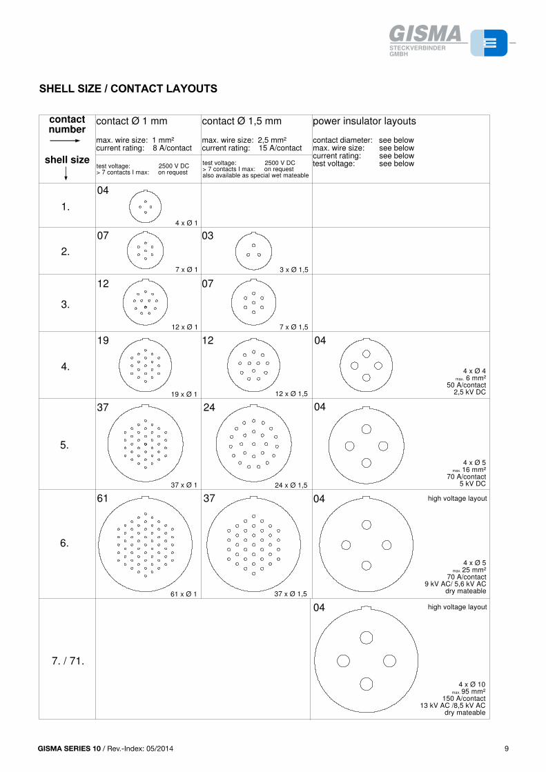
SHELL SIZE / CONTACT LAYOUTS
9
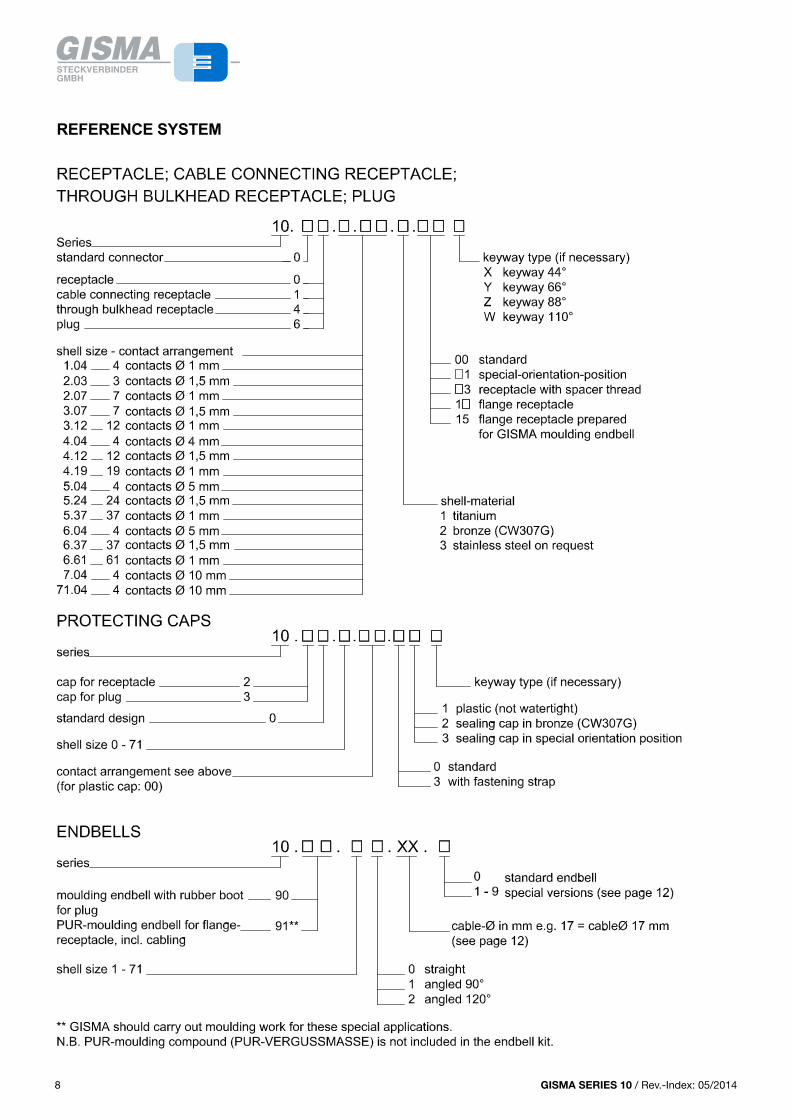
REFERENCE SYSTEM
88 GISMA SERIES 10 / Rev.-Index: 01/2013
GISMA SERIES 10 / Rev.-Index: 05/2014 9
PLUG
Size Contact arrangement Ø A Ø B C D E F SW G
1 4 x 1 30 16.9 27 33.5 45,5 55 26
2 3 x 1.5 ; 7 x 1 37 19.9 27 33.5 44 56 32
3 7 x 1.5 ; 12 x 1 39 24 27 33.5 45 56 34
4 12 x 1.5 ; 19 x 1 46.5 28.5 27 33.5 45 55 41
5 24 x 1.5 ; 37 x 1 58 41 30 37.2 50,5 55 54
6 37 x 1.5 ; 61 x 1 67 48 31 37 50 56 62
7 4 x 10 110 77 66.5 78 138 153 100
71 4 x 10 120 105 104.5 154 184 223 110
ENDBELL
Size Contact arrangementstandard endbell large cable Ø endbell
max. cable Ø A 1max. cable Ø A B ca. C ca. D ca.
1 4 x 1 14 28 98 142 16 (see dimensions size 3)
2 3 x 1.5 ; 7 x 1 14 28 98 142 16 (see dimensions size 3)
3 7 x 1.5 ; 12 x 1 16 34 109 160 22 (see dimensions size 4)
4 12 x 1.5 ; 19 x 1 20 42 107 157 31 (see dimensions size 5)
5 24 x 1.5 ; 37 x 1 31 52 113 219 42 (dimensions on request)
6 37 x 1.5 ; 61 x 1 31 52 113 207 52 (dimensions on request)
7 4 x 10 57 83 229 342 ---
71 4 x 10 57 83 128 433 ---
12
NEW: 120° AND 90° MOULDING ENDBELL WITH RUBBER BOOT
Size Ø A B Ø C SW D E F Ø G max. Ø H J K
1 30 27 35 26 --- --- 28 13 106 158
2 37 27 41 32 --- --- 28 13 99 160
3 39 27 42 34 156 162 34 15 114 195
4 46,5 27 49 41 --- --- 47 25 119 196
5 58 30 59 54 215 203 52 31 172 244
6 67 31 70 62 --- --- 52 42 198 280
7 110 66,5 --- 100 --- --- 83 --- --- ---
13
A
SW D
J
C
90°
K
B
HG
A
120
°
SW D
F
B
E
C
G
H
NEW: 120° AND 90° MOULDING ENDBELL WITH RUBBER BOOT
Size Ø A B Ø C SW D E F Ø G max. Ø H J K
1 30 27 35 26 --- --- 28 13 106 158
2 37 27 41 32 --- --- 28 13 99 160
3 39 27 42 34 156 162 34 15 114 195
4 46,5 27 49 41 --- --- 47 25 119 196
5 58 30 59 54 215 203 52 31 172 244
6 67 31 70 62 --- --- 52 42 198 280
7 110 66,5 --- 100 --- --- 83 --- --- ---
13
13GISMA SERIES 10 / Rev.-Index: 01/2013
SHELL SIZE / CONTACT LAYOUTS
9
REFERENCE SYSTEM
8
19 x Ø 1
37 x Ø 1 24 x Ø 1,5
4 x Ø 5max. 16 mm²
70 A/contact5 kV DC
04
04
4 x Ø 5max. 25 mm²
70 A/contact9 kV AC/ 5,6 kV AC
dry mateable
4 x Ø 10max. 95 mm²
150 A/contact13 kV AC /8,5 kV AC
dry mateable
37 x Ø 1,5
37
37
61
24
61 x Ø 1
7 x Ø 1,5
12 x Ø 1,5
3 x Ø 1,57 x Ø 1
12 x Ø 1
4 x Ø 1
5.
4.
3.
6.
04
07 03
12 07
19 12
2.
04
high voltage layout
high voltage layout
04
1.
7. / 71.
4 x Ø 4max. 6 mm²
50 A/contact2,5 kV DC
contact Ø 1 mm
max. wire size: 1 mm²current rating: 8 A/contact
contact Ø 1,5 mm
max. wire size: 2,5 mm²current rating: 15 A/contact
power insulator layouts
contact diameter: see belowmax. wire size: see belowcurrent rating: see belowtest voltage: see below
contact
number
shell sizetest voltage: 2500 V DC> 7 contacts I max: on request
test voltage: 2500 V DC> 7 contacts I max: on requestalso available as special wet mateable
9GISMA SERIES 10 / Rev.-Index: 01/2013
GISMA SERIES 10 / Rev.-Index: 05/201410
SHELL STYLES
5
COMPANY PROFILE
With more than 4000 different types, GISMA today is one of the leading manufactures of high-performance electrical and fibre optic and hybrid underwater and explosion proof connectors.
GISMA's success is based on:
1. A quality management system meeting the requirements of DIN ISO 9001 with DNV (Det Norske Veritas) certificate.
2. Consistency in meeting the needs of the customer.
3. Short and reliable delivery times.
4. Several services ranging from advising individual customers to the delivery of fully-tested, terminated and pressure tested cable assemblies.
Special orders are carried out quickly and efficiently using GISMA's own computer-aided design department, tooling and ultramodern computer controlled machines for production. With more than 95% of GISMA's production carried out in house, maximum flexibility is assured.
GISMA connectors are used world-wide in submarines, the offshore and chemical-, pump-, renewable industries and for underwater research. GISMA offers an extensive family of standard connectors with contact numbers from 1 - 265, voltages up to 11 kV and current ratings up to 1000 A in 18 different series.
All types of optical fibres, both single- and multi-mode, can be assembled with GISMA connectors.
Certificates of approval from well known test organisations such as TÜV (Technical Supervision Association), GL (German LLoyd), DNV (Det Norske Veritas) etc. are available at extra charge.
GISMA SERIES 10
The SERIES 10 described in this catalogue is designed for underwater operations down to 10.000 metres' depth. Thanks to the very high load capacity of the locking-screw thread, SERIES 10 is especially suitable for robust and frequent mating operations in the offshore industry. Except of those with high-voltage inserts (size 6 and 7), SERIES 10 connectors can be mated wet or underwater, up to a max. water-depth of 100 m. For underwater mating we recommend our fluid filled pressure balanced connectors SERIES 80. All SERIES 10 connectors can be exposed open-faced to water pressure.
With contact numbers from 3 - 61, current ratings up to 150 A and voltages up to 6.6 kV, the GISMA SERIES 10 comprises a wide range of high performance underwater electrical connectors.
At series 10 special designs are available on request
ATTENTION
Further documents have to be considered:
• Cabling instruction No.: Verkabelungsanleitung BR 10 BR 22 Stand 2010-48 (or newest version)• Handling instruction No.:HI-2007-001 (or newest version)
If series 10 connectors should be used for pressure balanced oil filled systems, please contact GISMA application engineering.
44 GISMA SERIES 10 / Rev.-Index: 01/2013
THROUGH BULKHEAD RECEPTACLE
Size Contact arrangement A ØB Ø C Ø C 1 SW D SW E F G H min H max J
1 4 x 1 22 35 23.5 25 32 27 5 19 21 47 97
2 3 x 1.5 ; 7 x 1 25 38 26.5 28 35 32 5 19 21 47 99
3 7 x 1.5 ; 12 x 1 30 45 32 34 41 36 5 21 21 47 99
4 4 x 4 ; 12 x 1.5 ; 19 x 1 34.5 50 36.5 38 46 41 5 21 21 47 99
5 4 x 5 ; 24 x 1.5 ; 37 x 1 49 70 51 53 64 60 5 24 20 50 104.5
6 37 x 1.5 ; 61 x 1 59 80 61 63 75 70 5 26 20 56 112.5
CABLE CONNECTING RECEPTACLE
Size Contact arrangement Ø A Ø B Ø C SW D E F G H J ca.
1 4 x 1 22 16.9 28 24 19 37,5 43,5 56 64
2 3 x 1.5 ; 7 x 1 25 19.9 30 26 19 37,5 43.5 56 63
3 7 x 1.5 ; 12 x 1 30 24 35 32 21 39,5 47,5 58 65
4 12 x 1.5 ; 19 x 1 34.5 28.5 40 36 21 41,5 47,5 58 65
5 24 x 1.5 ; 37 x 1 49 41 54 50 24 43 54 61 68
6 37 x 1.5 ; 61 x 1 59 48 64 60 26 47 55,5 63 70
7 4 x 10 94 77 110 100 52 98 130 141 184
11
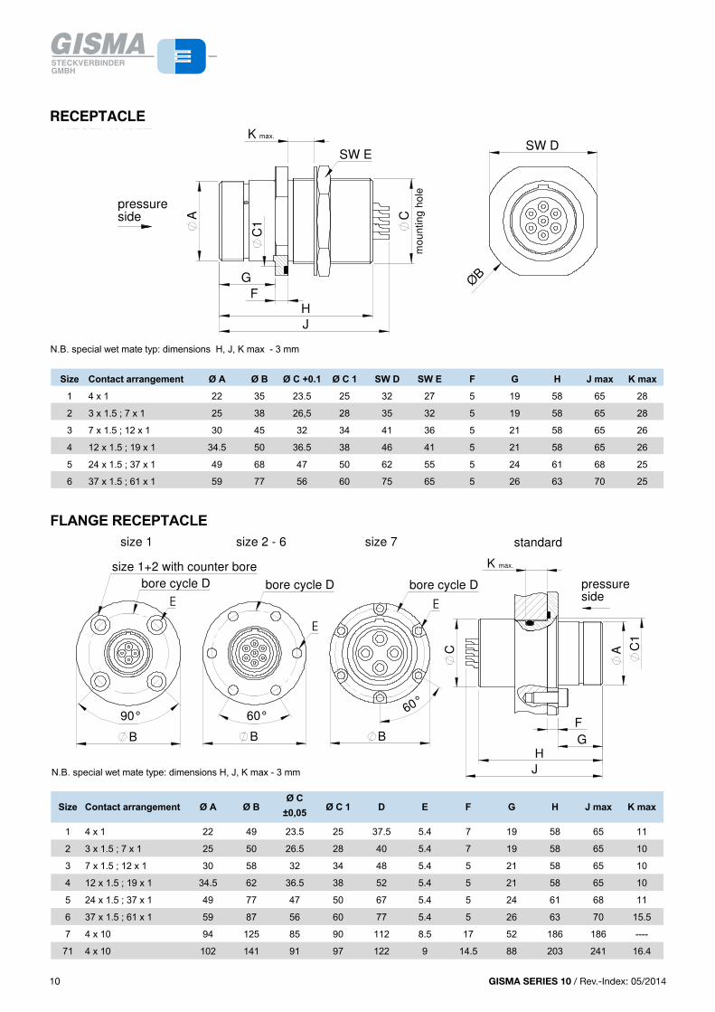
RECEPTACLE
N.B. special wet mate typ: dimensions H, J, K max - 3 mm
Size Contact arrangement Ø A Ø B Ø C +0.1 Ø C 1 SW D SW E F G H J max K max
1 4 x 1 22 35 23.5 25 32 27 5 19 58 65 28
2 3 x 1.5 ; 7 x 1 25 38 26,5 28 35 32 5 19 58 65 28
3 7 x 1.5 ; 12 x 1 30 45 32 34 41 36 5 21 58 65 26
4 12 x 1.5 ; 19 x 1 34.5 50 36.5 38 46 41 5 21 58 65 26
5 24 x 1.5 ; 37 x 1 49 68 47 50 62 55 5 24 61 68 25
6 37 x 1.5 ; 61 x 1 59 77 56 60 75 65 5 26 63 70 25
FLANGE RECEPTACLE
N.B. special wet mate type: dimensions H, J, K max - 3 mm
Size Contact arrangement Ø A Ø BØ C
±0,05 Ø C 1 D E F G H J max K max
1 4 x 1 22 49 23.5 25 37.5 5.4 7 19 58 65 11
2 3 x 1.5 ; 7 x 1 25 50 26.5 28 40 5.4 7 19 58 65 10
3 7 x 1.5 ; 12 x 1 30 58 32 34 48 5.4 5 21 58 65 10
4 12 x 1.5 ; 19 x 1 34.5 62 36.5 38 52 5.4 5 21 58 65 10
5 24 x 1.5 ; 37 x 1 49 77 47 50 67 5.4 5 24 61 68 11
6 37 x 1.5 ; 61 x 1 59 87 56 60 77 5.4 5 26 63 70 15.5
7 4 x 10 94 125 85 90 112 8.5 17 52 186 186 ----
71 4 x 10 102 141 91 97 122 9 14.5 88 203 241 16.4
10
THROUGH BULKHEAD RECEPTACLE
Size Contact arrangement A ØB Ø C Ø C 1 SW D SW E F G H min H max J
1 4 x 1 22 35 23.5 25 32 27 5 19 21 47 97
2 3 x 1.5 ; 7 x 1 25 38 26.5 28 35 32 5 19 21 47 99
3 7 x 1.5 ; 12 x 1 30 45 32 34 41 36 5 21 21 47 99
4 4 x 4 ; 12 x 1.5 ; 19 x 1 34.5 50 36.5 38 46 41 5 21 21 47 99
5 4 x 5 ; 24 x 1.5 ; 37 x 1 49 70 51 53 64 60 5 24 20 50 104.5
6 37 x 1.5 ; 61 x 1 59 80 61 63 75 70 5 26 20 56 112.5
CABLE CONNECTING RECEPTACLE
Size Contact arrangement Ø A Ø B Ø C SW D E F G H J ca.
1 4 x 1 22 16.9 28 24 19 37,5 43,5 56 64
2 3 x 1.5 ; 7 x 1 25 19.9 30 26 19 37,5 43.5 56 63
3 7 x 1.5 ; 12 x 1 30 24 35 32 21 39,5 47,5 58 65
4 12 x 1.5 ; 19 x 1 34.5 28.5 40 36 21 41,5 47,5 58 65
5 24 x 1.5 ; 37 x 1 49 41 54 50 24 43 54 61 68
6 37 x 1.5 ; 61 x 1 59 48 64 60 26 47 55,5 63 70
7 4 x 10 94 77 110 100 52 98 130 141 184
11
RECEPTACLE
N.B. special wet mate typ: dimensions H, J, K max - 3 mm
Size Contact arrangement Ø A Ø B Ø C +0.1 Ø C 1 SW D SW E F G H J max K max
1 4 x 1 22 35 23.5 25 32 27 5 19 58 65 28
2 3 x 1.5 ; 7 x 1 25 38 26,5 28 35 32 5 19 58 65 28
3 7 x 1.5 ; 12 x 1 30 45 32 34 41 36 5 21 58 65 26
4 12 x 1.5 ; 19 x 1 34.5 50 36.5 38 46 41 5 21 58 65 26
5 24 x 1.5 ; 37 x 1 49 68 47 50 62 55 5 24 61 68 25
6 37 x 1.5 ; 61 x 1 59 77 56 60 75 65 5 26 63 70 25
FLANGE RECEPTACLE
N.B. special wet mate type: dimensions H, J, K max - 3 mm
Size Contact arrangement Ø A Ø BØ C
±0,05 Ø C 1 D E F G H J max K max
1 4 x 1 22 49 23.5 25 37.5 5.4 7 19 58 65 11
2 3 x 1.5 ; 7 x 1 25 50 26.5 28 40 5.4 7 19 58 65 10
3 7 x 1.5 ; 12 x 1 30 58 32 34 48 5.4 5 21 58 65 10
4 12 x 1.5 ; 19 x 1 34.5 62 36.5 38 52 5.4 5 21 58 65 10
5 24 x 1.5 ; 37 x 1 49 77 47 50 67 5.4 5 24 61 68 11
6 37 x 1.5 ; 61 x 1 59 87 56 60 77 5.4 5 26 63 70 15.5
7 4 x 10 94 125 85 90 112 8.5 17 52 186 186 ----
71 4 x 10 102 141 91 97 122 9 14.5 88 203 241 16.4
10
90° 60°60°
size 2 - 6 size 7size 1
sidepressure
standard
G
F
C
H
J
A
K max.
C1
E
bore cycle D
size 1+2 with counter bore
B
E
bore cycle D
B
E
bore cycle D
B
THROUGH BULKHEAD RECEPTACLE
Size Contact arrangement A ØB Ø C Ø C 1 SW D SW E F G H min H max J
1 4 x 1 22 35 23.5 25 32 27 5 19 21 47 97
2 3 x 1.5 ; 7 x 1 25 38 26.5 28 35 32 5 19 21 47 99
3 7 x 1.5 ; 12 x 1 30 45 32 34 41 36 5 21 21 47 99
4 4 x 4 ; 12 x 1.5 ; 19 x 1 34.5 50 36.5 38 46 41 5 21 21 47 99
5 4 x 5 ; 24 x 1.5 ; 37 x 1 49 70 51 53 64 60 5 24 20 50 104.5
6 37 x 1.5 ; 61 x 1 59 80 61 63 75 70 5 26 20 56 112.5
CABLE CONNECTING RECEPTACLE
Size Contact arrangement Ø A Ø B Ø C SW D E F G H J ca.
1 4 x 1 22 16.9 28 24 19 37,5 43,5 56 64
2 3 x 1.5 ; 7 x 1 25 19.9 30 26 19 37,5 43.5 56 63
3 7 x 1.5 ; 12 x 1 30 24 35 32 21 39,5 47,5 58 65
4 12 x 1.5 ; 19 x 1 34.5 28.5 40 36 21 41,5 47,5 58 65
5 24 x 1.5 ; 37 x 1 49 41 54 50 24 43 54 61 68
6 37 x 1.5 ; 61 x 1 59 48 64 60 26 47 55,5 63 70
7 4 x 10 94 77 110 100 52 98 130 141 184
11
RECEPTACLE
N.B. special wet mate typ: dimensions H, J, K max - 3 mm
Size Contact arrangement Ø A Ø B Ø C +0.1 Ø C 1 SW D SW E F G H J max K max
1 4 x 1 22 35 23.5 25 32 27 5 19 58 65 28
2 3 x 1.5 ; 7 x 1 25 38 26,5 28 35 32 5 19 58 65 28
3 7 x 1.5 ; 12 x 1 30 45 32 34 41 36 5 21 58 65 26
4 12 x 1.5 ; 19 x 1 34.5 50 36.5 38 46 41 5 21 58 65 26
5 24 x 1.5 ; 37 x 1 49 68 47 50 62 55 5 24 61 68 25
6 37 x 1.5 ; 61 x 1 59 77 56 60 75 65 5 26 63 70 25
FLANGE RECEPTACLE
N.B. special wet mate type: dimensions H, J, K max - 3 mm
Size Contact arrangement Ø A Ø BØ C
±0,05 Ø C 1 D E F G H J max K max
1 4 x 1 22 49 23.5 25 37.5 5.4 7 19 58 65 11
2 3 x 1.5 ; 7 x 1 25 50 26.5 28 40 5.4 7 19 58 65 10
3 7 x 1.5 ; 12 x 1 30 58 32 34 48 5.4 5 21 58 65 10
4 12 x 1.5 ; 19 x 1 34.5 62 36.5 38 52 5.4 5 21 58 65 10
5 24 x 1.5 ; 37 x 1 49 77 47 50 67 5.4 5 24 61 68 11
6 37 x 1.5 ; 61 x 1 59 87 56 60 77 5.4 5 26 63 70 15.5
7 4 x 10 94 125 85 90 112 8.5 17 52 186 186 ----
71 4 x 10 102 141 91 97 122 9 14.5 88 203 241 16.4
10
SW E
pressure side
J
A
H
G
C1
F
C
SW D
ØB
10 GISMA SERIES 10 / Rev.-Index: 01/2013
SW E
pressure side
G
C1
HF
J
CA
K
mo
un
tin
g h
ole
SW D
ØB
max.
90° 60°60°
standardsize 7
side
size 1 size 2 - 6
pressure
mo
un
tin
g h
ole
J
H
AC
F
G
K max.
C1
E
bore cycle D
size 1+2 with counter bore
B
E
bore cycle D
B
E
bore cycle D
B
THROUGH BULKHEAD RECEPTACLE
Size Contact arrangement A ØB Ø C Ø C 1 SW D SW E F G H min H max J
1 4 x 1 22 35 23.5 25 32 27 5 19 21 47 97
2 3 x 1.5 ; 7 x 1 25 38 26.5 28 35 32 5 19 21 47 99
3 7 x 1.5 ; 12 x 1 30 45 32 34 41 36 5 21 21 47 99
4 4 x 4 ; 12 x 1.5 ; 19 x 1 34.5 50 36.5 38 46 41 5 21 21 47 99
5 4 x 5 ; 24 x 1.5 ; 37 x 1 49 70 51 53 64 60 5 24 20 50 104.5
6 37 x 1.5 ; 61 x 1 59 80 61 63 75 70 5 26 20 56 112.5
CABLE CONNECTING RECEPTACLE
Size Contact arrangement Ø A Ø B Ø C SW D E F G H J ca.
1 4 x 1 22 16.9 28 24 19 37,5 43,5 56 64
2 3 x 1.5 ; 7 x 1 25 19.9 30 26 19 37,5 43.5 56 63
3 7 x 1.5 ; 12 x 1 30 24 35 32 21 39,5 47,5 58 65
4 12 x 1.5 ; 19 x 1 34.5 28.5 40 36 21 41,5 47,5 58 65
5 24 x 1.5 ; 37 x 1 49 41 54 50 24 43 54 61 68
6 37 x 1.5 ; 61 x 1 59 48 64 60 26 47 55,5 63 70
7 4 x 10 94 77 110 100 52 98 130 141 184
11
RECEPTACLE
N.B. special wet mate typ: dimensions H, J, K max - 3 mm
Size Contact arrangement Ø A Ø B Ø C +0.1 Ø C 1 SW D SW E F G H J max K max
1 4 x 1 22 35 23.5 25 32 27 5 19 58 65 28
2 3 x 1.5 ; 7 x 1 25 38 26,5 28 35 32 5 19 58 65 28
3 7 x 1.5 ; 12 x 1 30 45 32 34 41 36 5 21 58 65 26
4 12 x 1.5 ; 19 x 1 34.5 50 36.5 38 46 41 5 21 58 65 26
5 24 x 1.5 ; 37 x 1 49 68 47 50 62 55 5 24 61 68 25
6 37 x 1.5 ; 61 x 1 59 77 56 60 75 65 5 26 63 70 25
FLANGE RECEPTACLE
N.B. special wet mate type: dimensions H, J, K max - 3 mm
Size Contact arrangement Ø A Ø BØ C
±0,05 Ø C 1 D E F G H J max K max
1 4 x 1 22 49 23.5 25 37.5 5.4 7 19 58 65 11
2 3 x 1.5 ; 7 x 1 25 50 26.5 28 40 5.4 7 19 58 65 10
3 7 x 1.5 ; 12 x 1 30 58 32 34 48 5.4 5 21 58 65 10
4 12 x 1.5 ; 19 x 1 34.5 62 36.5 38 52 5.4 5 21 58 65 10
5 24 x 1.5 ; 37 x 1 49 77 47 50 67 5.4 5 24 61 68 11
6 37 x 1.5 ; 61 x 1 59 87 56 60 77 5.4 5 26 63 70 15.5
7 4 x 10 94 125 85 90 112 8.5 17 52 186 186 ----
71 4 x 10 102 141 91 97 122 9 14.5 88 203 241 16.4
10
90° 60°60°
size 2 - 6 size 7size 1
sidepressure
standard
G
F
C
H
J
A
K max.
C1
E
bore cycle D
size 1+2 with counter bore
B
E
bore cycle D
B
E
bore cycle D
B
THROUGH BULKHEAD RECEPTACLE
Size Contact arrangement A ØB Ø C Ø C 1 SW D SW E F G H min H max J
1 4 x 1 22 35 23.5 25 32 27 5 19 21 47 97
2 3 x 1.5 ; 7 x 1 25 38 26.5 28 35 32 5 19 21 47 99
3 7 x 1.5 ; 12 x 1 30 45 32 34 41 36 5 21 21 47 99
4 4 x 4 ; 12 x 1.5 ; 19 x 1 34.5 50 36.5 38 46 41 5 21 21 47 99
5 4 x 5 ; 24 x 1.5 ; 37 x 1 49 70 51 53 64 60 5 24 20 50 104.5
6 37 x 1.5 ; 61 x 1 59 80 61 63 75 70 5 26 20 56 112.5
CABLE CONNECTING RECEPTACLE
Size Contact arrangement Ø A Ø B Ø C SW D E F G H J ca.
1 4 x 1 22 16.9 28 24 19 37,5 43,5 56 64
2 3 x 1.5 ; 7 x 1 25 19.9 30 26 19 37,5 43.5 56 63
3 7 x 1.5 ; 12 x 1 30 24 35 32 21 39,5 47,5 58 65
4 12 x 1.5 ; 19 x 1 34.5 28.5 40 36 21 41,5 47,5 58 65
5 24 x 1.5 ; 37 x 1 49 41 54 50 24 43 54 61 68
6 37 x 1.5 ; 61 x 1 59 48 64 60 26 47 55,5 63 70
7 4 x 10 94 77 110 100 52 98 130 141 184
11
THROUGH BULKHEAD RECEPTACLE
Size Contact arrangement A ØB Ø C Ø C 1 SW D SW E F G H min H max J
1 4 x 1 22 35 23.5 25 32 27 5 19 21 47 97
2 3 x 1.5 ; 7 x 1 25 38 26.5 28 35 32 5 19 21 47 99
3 7 x 1.5 ; 12 x 1 30 45 32 34 41 36 5 21 21 47 99
4 4 x 4 ; 12 x 1.5 ; 19 x 1 34.5 50 36.5 38 46 41 5 21 21 47 99
5 4 x 5 ; 24 x 1.5 ; 37 x 1 49 70 51 53 64 60 5 24 20 50 104.5
6 37 x 1.5 ; 61 x 1 59 80 61 63 75 70 5 26 20 56 112.5
CABLE CONNECTING RECEPTACLE
Size Contact arrangement Ø A Ø B Ø C SW D E F G H J ca.
1 4 x 1 22 16.9 28 24 19 37,5 43,5 56 64
2 3 x 1.5 ; 7 x 1 25 19.9 30 26 19 37,5 43.5 56 63
3 7 x 1.5 ; 12 x 1 30 24 35 32 21 39,5 47,5 58 65
4 12 x 1.5 ; 19 x 1 34.5 28.5 40 36 21 41,5 47,5 58 65
5 24 x 1.5 ; 37 x 1 49 41 54 50 24 43 54 61 68
6 37 x 1.5 ; 61 x 1 59 48 64 60 26 47 55,5 63 70
7 4 x 10 94 77 110 100 52 98 130 141 184
11
RECEPTACLE
N.B. special wet mate typ: dimensions H, J, K max - 3 mm
Size Contact arrangement Ø A Ø B Ø C +0.1 Ø C 1 SW D SW E F G H J max K max
1 4 x 1 22 35 23.5 25 32 27 5 19 58 65 28
2 3 x 1.5 ; 7 x 1 25 38 26,5 28 35 32 5 19 58 65 28
3 7 x 1.5 ; 12 x 1 30 45 32 34 41 36 5 21 58 65 26
4 12 x 1.5 ; 19 x 1 34.5 50 36.5 38 46 41 5 21 58 65 26
5 24 x 1.5 ; 37 x 1 49 68 47 50 62 55 5 24 61 68 25
6 37 x 1.5 ; 61 x 1 59 77 56 60 75 65 5 26 63 70 25
FLANGE RECEPTACLE
N.B. special wet mate type: dimensions H, J, K max - 3 mm
Size Contact arrangement Ø A Ø BØ C
±0,05 Ø C 1 D E F G H J max K max
1 4 x 1 22 49 23.5 25 37.5 5.4 7 19 58 65 11
2 3 x 1.5 ; 7 x 1 25 50 26.5 28 40 5.4 7 19 58 65 10
3 7 x 1.5 ; 12 x 1 30 58 32 34 48 5.4 5 21 58 65 10
4 12 x 1.5 ; 19 x 1 34.5 62 36.5 38 52 5.4 5 21 58 65 10
5 24 x 1.5 ; 37 x 1 49 77 47 50 67 5.4 5 24 61 68 11
6 37 x 1.5 ; 61 x 1 59 87 56 60 77 5.4 5 26 63 70 15.5
7 4 x 10 94 125 85 90 112 8.5 17 52 186 186 ----
71 4 x 10 102 141 91 97 122 9 14.5 88 203 241 16.4
10
SW E
pressure side
J
A
H
G
C1
F
C
SW D
ØB
10 GISMA SERIES 10 / Rev.-Index: 01/201310
RECEPTACLE
N.B. special wet mate typ: dimensions H, J, K max - 3 mm
Size Contact arrangement Ø A Ø B Ø C +0.1 Ø C 1 SW D SW E F G H J max K max
1 4 x 1 22 35 23.5 25 32 27 5 19 58 65 28
2 3 x 1.5 ; 7 x 1 25 38 26.5 28 35 32 5 19 58 65 28
3 7 x 1.5 ; 12 x 1 30 45 32 34 41 36 5 21 58 65 26
4 12 x 1.5 ; 19 x 1 34.5 50 36.5 38 46 41 5 21 58 65 26
5 24 x 1.5 ; 37 x 1 49 68 47 50 62 55 5 24 61 68 25
6 37 x 1.5 ; 61 x 1 59 77 56 60 75 65 5 26 63 70 25
FLANGE RECEPTACLE
N.B. special wet mate type: dimensions H, J, K max - 3 mm
Size Contact arrangement Ø A Ø BØ C
±0,05 Ø C 1 D E F G H J max K max
1 4 x 1 22 49 23.5 25 37.5 5.4 7 19 58 65 11
2 3 x 1.5 ; 7 x 1 25 50 26.5 28 40 5.4 7 19 58 65 10
3 7 x 1.5 ; 12 x 1 30 58 32 34 48 5.4 5 21 58 65 10
4 12 x 1.5 ; 19 x 1 34.5 62 36.5 38 52 5.4 5 21 58 65 10
5 24 x 1.5 ; 37 x 1 49 77 47 50 67 5.4 5 24 61 68 11
6 37 x 1.5 ; 61 x 1 59 87 56 60 77 5.4 5 26 63 70 15.5
7 4 x 10 94 125 85 90 112 8.5 17 52 186 186 ----
71 4 x 10 102 141 91 97 122 9 14.5 88 203 241 16.4
10
RECEPTACLE N.B. special wet mate typ: dimensions H, J, K max - 3 mm
Size Contact arrangement Ø A Ø B Ø C +0.1 Ø C 1 SW D SW E F G H J max K max 1 4 x 1 22 35 23.5 25 32 27 5 19 58 65 28 2 3 x 1.5 ; 7 x 1 25 38 26.5 28 35 32 5 19 58 65 28 3 7 x 1.5 ; 12 x 1 30 45 32 34 41 36 5 21 58 65 26 4 12 x 1.5 ; 19 x 1 34.5 50 36.5 38 46 41 5 21 58 65 26 5 24 x 1.5 ; 37 x 1 49 68 47 50 62 55 5 24 61 68 25
6 37 x 1.5 ; 61 x 1 59 77 56 60 75 65 5 26 63 70 25
FLANGE RECEPTACLE N.B. special wet mate type: dimensions H, J, K max - 3 mm
Size Contact arrangement Ø A Ø B Ø C
±0,05 Ø C 1 D E F G H J max K max
1 4 x 1 22 49 23.5 25 37.5 5.4 7 19 58 65 11 2 3 x 1.5 ; 7 x 1 25 50 26.5 28 40 5.4 7 19 58 65 10 3 7 x 1.5 ; 12 x 1 30 58 32 34 48 5.4 5 21 58 65 10 4 12 x 1.5 ; 19 x 1 34.5 62 36.5 38 52 5.4 5 21 58 65 10 5 24 x 1.5 ; 37 x 1 49 77 47 50 67 5.4 5 24 61 68 11 6 37 x 1.5 ; 61 x 1 59 87 56 60 77 5.4 5 26 63 70 15.5
7 4 x 10 94 125 85 90 112 8.5 17 52 186 186 ---- 71 4 x 10 102 141 91 97 122 9 14.5 88 203 241 16.4
THROUGH BULKHEAD RECEPTACLE
Size Contact arrangement A ØB Ø C Ø C 1 SW D SW E F G H min H max J
1 4 x 1 22 35 23.5 25 32 27 5 19 21 47 97
2 3 x 1.5 ; 7 x 1 25 38 26.5 28 35 32 5 19 21 47 99
3 7 x 1.5 ; 12 x 1 30 45 32 34 41 36 5 21 21 47 99
4 4 x 4 ; 12 x 1.5 ; 19 x 1 34.5 50 36.5 38 46 41 5 21 21 47 99
5 4 x 5 ; 24 x 1.5 ; 37 x 1 49 70 51 53 64 60 5 24 20 50 104.5
6 37 x 1.5 ; 61 x 1 59 80 61 63 75 70 5 26 20 56 112.5
CABLE CONNECTING RECEPTACLE
Size Contact arrangement Ø A Ø B Ø C SW D E F G H J ca.
1 4 x 1 22 16.9 28 24 19 37,5 43,5 56 64
2 3 x 1.5 ; 7 x 1 25 19.9 30 26 19 37,5 43.5 56 63
3 7 x 1.5 ; 12 x 1 30 24 35 32 21 39,5 47,5 58 65
4 12 x 1.5 ; 19 x 1 34.5 28.5 40 36 21 41,5 47,5 58 65
5 24 x 1.5 ; 37 x 1 49 41 54 50 24 43 54 61 68
6 37 x 1.5 ; 61 x 1 59 48 64 60 26 47 55,5 63 70
7 4 x 10 94 77 110 100 52 98 130 141 184
11
RECEPTACLE
N.B. special wet mate typ: dimensions H, J, K max - 3 mm
Size Contact arrangement Ø A Ø B Ø C +0.1 Ø C 1 SW D SW E F G H J max K max
1 4 x 1 22 35 23.5 25 32 27 5 19 58 65 28
2 3 x 1.5 ; 7 x 1 25 38 26,5 28 35 32 5 19 58 65 28
3 7 x 1.5 ; 12 x 1 30 45 32 34 41 36 5 21 58 65 26
4 12 x 1.5 ; 19 x 1 34.5 50 36.5 38 46 41 5 21 58 65 26
5 24 x 1.5 ; 37 x 1 49 68 47 50 62 55 5 24 61 68 25
6 37 x 1.5 ; 61 x 1 59 77 56 60 75 65 5 26 63 70 25
FLANGE RECEPTACLE
N.B. special wet mate type: dimensions H, J, K max - 3 mm
Size Contact arrangement Ø A Ø BØ C
±0,05 Ø C 1 D E F G H J max K max
1 4 x 1 22 49 23.5 25 37.5 5.4 7 19 58 65 11
2 3 x 1.5 ; 7 x 1 25 50 26.5 28 40 5.4 7 19 58 65 10
3 7 x 1.5 ; 12 x 1 30 58 32 34 48 5.4 5 21 58 65 10
4 12 x 1.5 ; 19 x 1 34.5 62 36.5 38 52 5.4 5 21 58 65 10
5 24 x 1.5 ; 37 x 1 49 77 47 50 67 5.4 5 24 61 68 11
6 37 x 1.5 ; 61 x 1 59 87 56 60 77 5.4 5 26 63 70 15.5
7 4 x 10 94 125 85 90 112 8.5 17 52 186 186 ----
71 4 x 10 102 141 91 97 122 9 14.5 88 203 241 16.4
10
90° 60°60°
size 2 - 6 size 7size 1
sidepressure
standard
G
F
C
H
J
A
K max.
C1
E
bore cycle D
size 1+2 with counter bore
B
E
bore cycle D
B
E
bore cycle D
B
THROUGH BULKHEAD RECEPTACLE
Size Contact arrangement A ØB Ø C Ø C 1 SW D SW E F G H min H max J
1 4 x 1 22 35 23.5 25 32 27 5 19 21 47 97
2 3 x 1.5 ; 7 x 1 25 38 26.5 28 35 32 5 19 21 47 99
3 7 x 1.5 ; 12 x 1 30 45 32 34 41 36 5 21 21 47 99
4 4 x 4 ; 12 x 1.5 ; 19 x 1 34.5 50 36.5 38 46 41 5 21 21 47 99
5 4 x 5 ; 24 x 1.5 ; 37 x 1 49 70 51 53 64 60 5 24 20 50 104.5
6 37 x 1.5 ; 61 x 1 59 80 61 63 75 70 5 26 20 56 112.5
CABLE CONNECTING RECEPTACLE
Size Contact arrangement Ø A Ø B Ø C SW D E F G H J ca.
1 4 x 1 22 16.9 28 24 19 37,5 43,5 56 64
2 3 x 1.5 ; 7 x 1 25 19.9 30 26 19 37,5 43.5 56 63
3 7 x 1.5 ; 12 x 1 30 24 35 32 21 39,5 47,5 58 65
4 12 x 1.5 ; 19 x 1 34.5 28.5 40 36 21 41,5 47,5 58 65
5 24 x 1.5 ; 37 x 1 49 41 54 50 24 43 54 61 68
6 37 x 1.5 ; 61 x 1 59 48 64 60 26 47 55,5 63 70
7 4 x 10 94 77 110 100 52 98 130 141 184
11
THROUGH BULKHEAD RECEPTACLE
Size Contact arrangement A ØB Ø C Ø C 1 SW D SW E F G H min H max J
1 4 x 1 22 35 23.5 25 32 27 5 19 21 47 97
2 3 x 1.5 ; 7 x 1 25 38 26.5 28 35 32 5 19 21 47 99
3 7 x 1.5 ; 12 x 1 30 45 32 34 41 36 5 21 21 47 99
4 4 x 4 ; 12 x 1.5 ; 19 x 1 34.5 50 36.5 38 46 41 5 21 21 47 99
5 4 x 5 ; 24 x 1.5 ; 37 x 1 49 70 51 53 64 60 5 24 20 50 104.5
6 37 x 1.5 ; 61 x 1 59 80 61 63 75 70 5 26 20 56 112.5
CABLE CONNECTING RECEPTACLE
Size Contact arrangement Ø A Ø B Ø C SW D E F G H J ca.
1 4 x 1 22 16.9 28 24 19 37,5 43,5 56 64
2 3 x 1.5 ; 7 x 1 25 19.9 30 26 19 37,5 43.5 56 63
3 7 x 1.5 ; 12 x 1 30 24 35 32 21 39,5 47,5 58 65
4 12 x 1.5 ; 19 x 1 34.5 28.5 40 36 21 41,5 47,5 58 65
5 24 x 1.5 ; 37 x 1 49 41 54 50 24 43 54 61 68
6 37 x 1.5 ; 61 x 1 59 48 64 60 26 47 55,5 63 70
7 4 x 10 94 77 110 100 52 98 130 141 184
11
RECEPTACLE
N.B. special wet mate typ: dimensions H, J, K max - 3 mm
Size Contact arrangement Ø A Ø B Ø C +0.1 Ø C 1 SW D SW E F G H J max K max
1 4 x 1 22 35 23.5 25 32 27 5 19 58 65 28
2 3 x 1.5 ; 7 x 1 25 38 26,5 28 35 32 5 19 58 65 28
3 7 x 1.5 ; 12 x 1 30 45 32 34 41 36 5 21 58 65 26
4 12 x 1.5 ; 19 x 1 34.5 50 36.5 38 46 41 5 21 58 65 26
5 24 x 1.5 ; 37 x 1 49 68 47 50 62 55 5 24 61 68 25
6 37 x 1.5 ; 61 x 1 59 77 56 60 75 65 5 26 63 70 25
FLANGE RECEPTACLE
N.B. special wet mate type: dimensions H, J, K max - 3 mm
Size Contact arrangement Ø A Ø BØ C
±0,05 Ø C 1 D E F G H J max K max
1 4 x 1 22 49 23.5 25 37.5 5.4 7 19 58 65 11
2 3 x 1.5 ; 7 x 1 25 50 26.5 28 40 5.4 7 19 58 65 10
3 7 x 1.5 ; 12 x 1 30 58 32 34 48 5.4 5 21 58 65 10
4 12 x 1.5 ; 19 x 1 34.5 62 36.5 38 52 5.4 5 21 58 65 10
5 24 x 1.5 ; 37 x 1 49 77 47 50 67 5.4 5 24 61 68 11
6 37 x 1.5 ; 61 x 1 59 87 56 60 77 5.4 5 26 63 70 15.5
7 4 x 10 94 125 85 90 112 8.5 17 52 186 186 ----
71 4 x 10 102 141 91 97 122 9 14.5 88 203 241 16.4
10
SW E
pressure side
J
A
H
G
C1
F
C
SW D
ØB
10 GISMA SERIES 10 / Rev.-Index: 01/2013
SW E
pressure side
G
C1
HF
J
CA
K
mo
un
tin
g h
ole
SW D
ØB
max.
90° 60°60°
standardsize 7
side
size 1 size 2 - 6
pressure
mo
un
tin
g h
ole
J
H
AC
F
G
K max.
C1
E
bore cycle D
size 1+2 with counter bore
B
E
bore cycle D
B
E
bore cycle D
B
THROUGH BULKHEAD RECEPTACLE
Size Contact arrangement A ØB Ø C Ø C 1 SW D SW E F G H min H max J
1 4 x 1 22 35 23.5 25 32 27 5 19 21 47 97
2 3 x 1.5 ; 7 x 1 25 38 26.5 28 35 32 5 19 21 47 99
3 7 x 1.5 ; 12 x 1 30 45 32 34 41 36 5 21 21 47 99
4 4 x 4 ; 12 x 1.5 ; 19 x 1 34.5 50 36.5 38 46 41 5 21 21 47 99
5 4 x 5 ; 24 x 1.5 ; 37 x 1 49 70 51 53 64 60 5 24 20 50 104.5
6 37 x 1.5 ; 61 x 1 59 80 61 63 75 70 5 26 20 56 112.5
CABLE CONNECTING RECEPTACLE
Size Contact arrangement Ø A Ø B Ø C SW D E F G H J ca.
1 4 x 1 22 16.9 28 24 19 37,5 43,5 56 64
2 3 x 1.5 ; 7 x 1 25 19.9 30 26 19 37,5 43.5 56 63
3 7 x 1.5 ; 12 x 1 30 24 35 32 21 39,5 47,5 58 65
4 12 x 1.5 ; 19 x 1 34.5 28.5 40 36 21 41,5 47,5 58 65
5 24 x 1.5 ; 37 x 1 49 41 54 50 24 43 54 61 68
6 37 x 1.5 ; 61 x 1 59 48 64 60 26 47 55,5 63 70
7 4 x 10 94 77 110 100 52 98 130 141 184
11
RECEPTACLE
N.B. special wet mate typ: dimensions H, J, K max - 3 mm
Size Contact arrangement Ø A Ø B Ø C +0.1 Ø C 1 SW D SW E F G H J max K max
1 4 x 1 22 35 23.5 25 32 27 5 19 58 65 28
2 3 x 1.5 ; 7 x 1 25 38 26,5 28 35 32 5 19 58 65 28
3 7 x 1.5 ; 12 x 1 30 45 32 34 41 36 5 21 58 65 26
4 12 x 1.5 ; 19 x 1 34.5 50 36.5 38 46 41 5 21 58 65 26
5 24 x 1.5 ; 37 x 1 49 68 47 50 62 55 5 24 61 68 25
6 37 x 1.5 ; 61 x 1 59 77 56 60 75 65 5 26 63 70 25
FLANGE RECEPTACLE
N.B. special wet mate type: dimensions H, J, K max - 3 mm
Size Contact arrangement Ø A Ø BØ C
±0,05 Ø C 1 D E F G H J max K max
1 4 x 1 22 49 23.5 25 37.5 5.4 7 19 58 65 11
2 3 x 1.5 ; 7 x 1 25 50 26.5 28 40 5.4 7 19 58 65 10
3 7 x 1.5 ; 12 x 1 30 58 32 34 48 5.4 5 21 58 65 10
4 12 x 1.5 ; 19 x 1 34.5 62 36.5 38 52 5.4 5 21 58 65 10
5 24 x 1.5 ; 37 x 1 49 77 47 50 67 5.4 5 24 61 68 11
6 37 x 1.5 ; 61 x 1 59 87 56 60 77 5.4 5 26 63 70 15.5
7 4 x 10 94 125 85 90 112 8.5 17 52 186 186 ----
71 4 x 10 102 141 91 97 122 9 14.5 88 203 241 16.4
10
THROUGH BULKHEAD RECEPTACLE
Size Contact arrangement A ØB Ø C Ø C 1 SW D SW E F G H min H max J
1 4 x 1 22 35 23.5 25 32 27 5 19 21 47 97
2 3 x 1.5 ; 7 x 1 25 38 26.5 28 35 32 5 19 21 47 99
3 7 x 1.5 ; 12 x 1 30 45 32 34 41 36 5 21 21 47 99
4 4 x 4 ; 12 x 1.5 ; 19 x 1 34.5 50 36.5 38 46 41 5 21 21 47 99
5 4 x 5 ; 24 x 1.5 ; 37 x 1 49 70 51 53 64 60 5 24 20 50 104.5
6 37 x 1.5 ; 61 x 1 59 80 61 63 75 70 5 26 20 56 112.5
CABLE CONNECTING RECEPTACLE
Size Contact arrangement Ø A Ø B Ø C SW D E F G H J ca.
1 4 x 1 22 16.9 28 24 19 37,5 43,5 56 64
2 3 x 1.5 ; 7 x 1 25 19.9 30 26 19 37,5 43.5 56 63
3 7 x 1.5 ; 12 x 1 30 24 35 32 21 39,5 47,5 58 65
4 12 x 1.5 ; 19 x 1 34.5 28.5 40 36 21 41,5 47,5 58 65
5 24 x 1.5 ; 37 x 1 49 41 54 50 24 43 54 61 68
6 37 x 1.5 ; 61 x 1 59 48 64 60 26 47 55,5 63 70
7 4 x 10 94 77 110 100 52 98 130 141 184
11
RECEPTACLE
N.B. special wet mate typ: dimensions H, J, K max - 3 mm
Size Contact arrangement Ø A Ø B Ø C +0.1 Ø C 1 SW D SW E F G H J max K max
1 4 x 1 22 35 23.5 25 32 27 5 19 58 65 28
2 3 x 1.5 ; 7 x 1 25 38 26,5 28 35 32 5 19 58 65 28
3 7 x 1.5 ; 12 x 1 30 45 32 34 41 36 5 21 58 65 26
4 12 x 1.5 ; 19 x 1 34.5 50 36.5 38 46 41 5 21 58 65 26
5 24 x 1.5 ; 37 x 1 49 68 47 50 62 55 5 24 61 68 25
6 37 x 1.5 ; 61 x 1 59 77 56 60 75 65 5 26 63 70 25
FLANGE RECEPTACLE
N.B. special wet mate type: dimensions H, J, K max - 3 mm
Size Contact arrangement Ø A Ø BØ C
±0,05 Ø C 1 D E F G H J max K max
1 4 x 1 22 49 23.5 25 37.5 5.4 7 19 58 65 11
2 3 x 1.5 ; 7 x 1 25 50 26.5 28 40 5.4 7 19 58 65 10
3 7 x 1.5 ; 12 x 1 30 58 32 34 48 5.4 5 21 58 65 10
4 12 x 1.5 ; 19 x 1 34.5 62 36.5 38 52 5.4 5 21 58 65 10
5 24 x 1.5 ; 37 x 1 49 77 47 50 67 5.4 5 24 61 68 11
6 37 x 1.5 ; 61 x 1 59 87 56 60 77 5.4 5 26 63 70 15.5
7 4 x 10 94 125 85 90 112 8.5 17 52 186 186 ----
71 4 x 10 102 141 91 97 122 9 14.5 88 203 241 16.4
10
RECEPTACLE
N.B. special wet mate typ: dimensions H, J, K max - 3 mm
Size Contact arrangement Ø A Ø B Ø C +0.1 Ø C 1 SW D SW E F G H J max K max
1 4 x 1 22 35 23.5 25 32 27 5 19 58 65 28
2 3 x 1.5 ; 7 x 1 25 38 26,5 28 35 32 5 19 58 65 28
3 7 x 1.5 ; 12 x 1 30 45 32 34 41 36 5 21 58 65 26
4 12 x 1.5 ; 19 x 1 34.5 50 36.5 38 46 41 5 21 58 65 26
5 24 x 1.5 ; 37 x 1 49 68 47 50 62 55 5 24 61 68 25
6 37 x 1.5 ; 61 x 1 59 77 56 60 75 65 5 26 63 70 25
FLANGE RECEPTACLE
N.B. special wet mate type: dimensions H, J, K max - 3 mm
Size Contact arrangement Ø A Ø BØ C
±0,05 Ø C 1 D E F G H J max K max
1 4 x 1 22 49 23.5 25 37.5 5.4 7 19 58 65 11
2 3 x 1.5 ; 7 x 1 25 50 26.5 28 40 5.4 7 19 58 65 10
3 7 x 1.5 ; 12 x 1 30 58 32 34 48 5.4 5 21 58 65 10
4 12 x 1.5 ; 19 x 1 34.5 62 36.5 38 52 5.4 5 21 58 65 10
5 24 x 1.5 ; 37 x 1 49 77 47 50 67 5.4 5 24 61 68 11
6 37 x 1.5 ; 61 x 1 59 87 56 60 77 5.4 5 26 63 70 15.5
7 4 x 10 94 125 85 90 112 8.5 17 52 186 186 ----
71 4 x 10 102 141 91 97 122 9 14.5 88 203 241 16.4
10
90° 60°60°
size 2 - 6 size 7size 1
sidepressure
standard
G
F
C
H
J
A
K max.
C1
E
bore cycle D
size 1+2 with counter bore
B
E
bore cycle D
B
E
bore cycle D
B
THROUGH BULKHEAD RECEPTACLE
Size Contact arrangement A ØB Ø C Ø C 1 SW D SW E F G H min H max J
1 4 x 1 22 35 23.5 25 32 27 5 19 21 47 97
2 3 x 1.5 ; 7 x 1 25 38 26.5 28 35 32 5 19 21 47 99
3 7 x 1.5 ; 12 x 1 30 45 32 34 41 36 5 21 21 47 99
4 4 x 4 ; 12 x 1.5 ; 19 x 1 34.5 50 36.5 38 46 41 5 21 21 47 99
5 4 x 5 ; 24 x 1.5 ; 37 x 1 49 70 51 53 64 60 5 24 20 50 104.5
6 37 x 1.5 ; 61 x 1 59 80 61 63 75 70 5 26 20 56 112.5
CABLE CONNECTING RECEPTACLE
Size Contact arrangement Ø A Ø B Ø C SW D E F G H J ca.
1 4 x 1 22 16.9 28 24 19 37,5 43,5 56 64
2 3 x 1.5 ; 7 x 1 25 19.9 30 26 19 37,5 43.5 56 63
3 7 x 1.5 ; 12 x 1 30 24 35 32 21 39,5 47,5 58 65
4 12 x 1.5 ; 19 x 1 34.5 28.5 40 36 21 41,5 47,5 58 65
5 24 x 1.5 ; 37 x 1 49 41 54 50 24 43 54 61 68
6 37 x 1.5 ; 61 x 1 59 48 64 60 26 47 55,5 63 70
7 4 x 10 94 77 110 100 52 98 130 141 184
11
THROUGH BULKHEAD RECEPTACLE
Size Contact arrangement A ØB Ø C Ø C 1 SW D SW E F G H min H max J
1 4 x 1 22 35 23.5 25 32 27 5 19 21 47 97
2 3 x 1.5 ; 7 x 1 25 38 26.5 28 35 32 5 19 21 47 99
3 7 x 1.5 ; 12 x 1 30 45 32 34 41 36 5 21 21 47 99
4 4 x 4 ; 12 x 1.5 ; 19 x 1 34.5 50 36.5 38 46 41 5 21 21 47 99
5 4 x 5 ; 24 x 1.5 ; 37 x 1 49 70 51 53 64 60 5 24 20 50 104.5
6 37 x 1.5 ; 61 x 1 59 80 61 63 75 70 5 26 20 56 112.5
CABLE CONNECTING RECEPTACLE
Size Contact arrangement Ø A Ø B Ø C SW D E F G H J ca.
1 4 x 1 22 16.9 28 24 19 37,5 43,5 56 64
2 3 x 1.5 ; 7 x 1 25 19.9 30 26 19 37,5 43.5 56 63
3 7 x 1.5 ; 12 x 1 30 24 35 32 21 39,5 47,5 58 65
4 12 x 1.5 ; 19 x 1 34.5 28.5 40 36 21 41,5 47,5 58 65
5 24 x 1.5 ; 37 x 1 49 41 54 50 24 43 54 61 68
6 37 x 1.5 ; 61 x 1 59 48 64 60 26 47 55,5 63 70
7 4 x 10 94 77 110 100 52 98 130 141 184
11
RECEPTACLE
N.B. special wet mate typ: dimensions H, J, K max - 3 mm
Size Contact arrangement Ø A Ø B Ø C +0.1 Ø C 1 SW D SW E F G H J max K max
1 4 x 1 22 35 23.5 25 32 27 5 19 58 65 28
2 3 x 1.5 ; 7 x 1 25 38 26,5 28 35 32 5 19 58 65 28
3 7 x 1.5 ; 12 x 1 30 45 32 34 41 36 5 21 58 65 26
4 12 x 1.5 ; 19 x 1 34.5 50 36.5 38 46 41 5 21 58 65 26
5 24 x 1.5 ; 37 x 1 49 68 47 50 62 55 5 24 61 68 25
6 37 x 1.5 ; 61 x 1 59 77 56 60 75 65 5 26 63 70 25
FLANGE RECEPTACLE
N.B. special wet mate type: dimensions H, J, K max - 3 mm
Size Contact arrangement Ø A Ø BØ C
±0,05 Ø C 1 D E F G H J max K max
1 4 x 1 22 49 23.5 25 37.5 5.4 7 19 58 65 11
2 3 x 1.5 ; 7 x 1 25 50 26.5 28 40 5.4 7 19 58 65 10
3 7 x 1.5 ; 12 x 1 30 58 32 34 48 5.4 5 21 58 65 10
4 12 x 1.5 ; 19 x 1 34.5 62 36.5 38 52 5.4 5 21 58 65 10
5 24 x 1.5 ; 37 x 1 49 77 47 50 67 5.4 5 24 61 68 11
6 37 x 1.5 ; 61 x 1 59 87 56 60 77 5.4 5 26 63 70 15.5
7 4 x 10 94 125 85 90 112 8.5 17 52 186 186 ----
71 4 x 10 102 141 91 97 122 9 14.5 88 203 241 16.4
10
SW E
pressure side
J
A
H
G
C1
F
C
SW D
ØB
10 GISMA SERIES 10 / Rev.-Index: 01/2013
SW E
pressure side
G
C1
HF
J
CA
K
mo
un
tin
g h
ole
SW D
ØB
max.
90° 60°60°
standardsize 7
side
size 1 size 2 - 6
pressure
mo
un
tin
g h
ole
J
H
AC
F
G
K max.
C1
E
bore cycle D
size 1+2 with counter bore
B
E
bore cycle D
B
E
bore cycle D
B
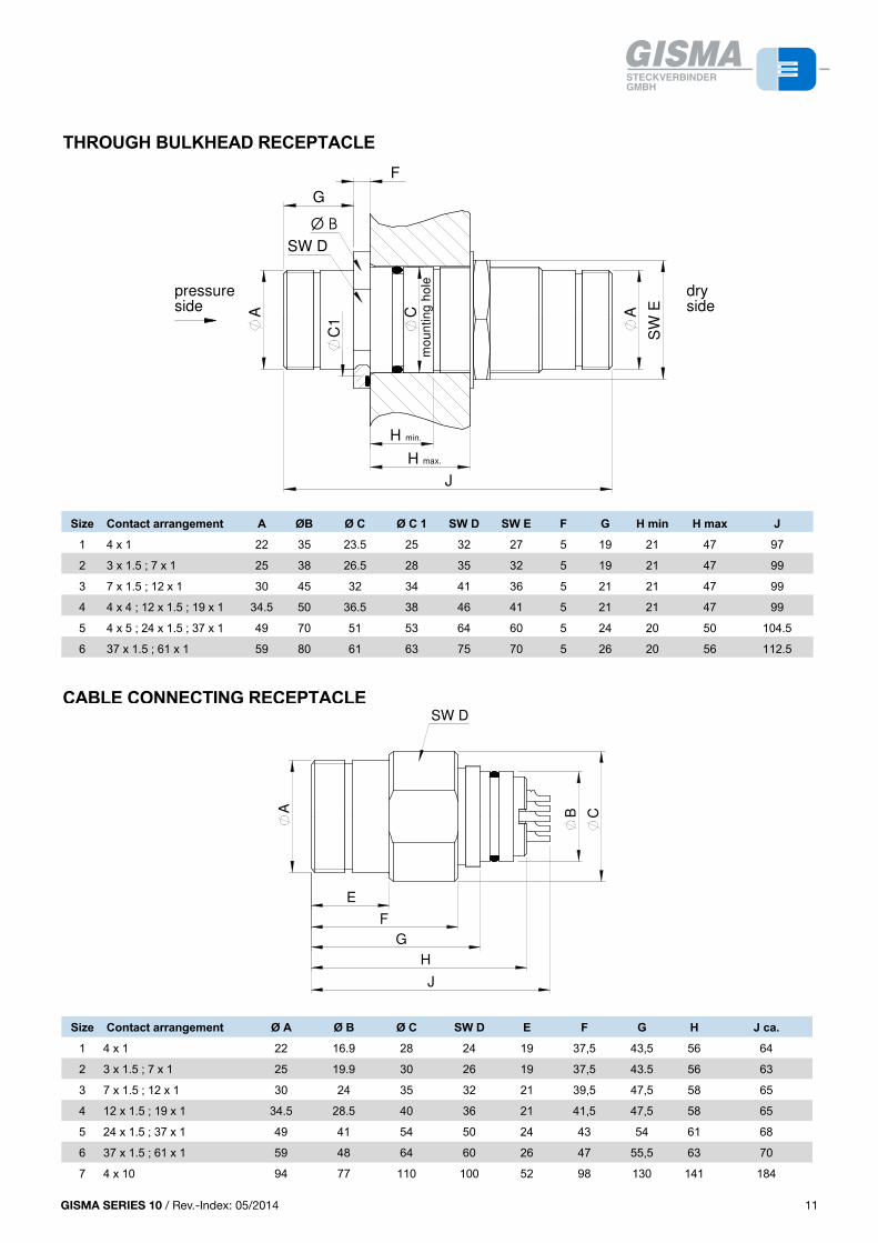
GISMA SERIES 10 / Rev.-Index: 05/2014 11
PLUG
Size Contact arrangement Ø A Ø B C D E F SW G
1 4 x 1 30 16.9 27 33.5 45,5 55 26
2 3 x 1.5 ; 7 x 1 37 19.9 27 33.5 44 56 32
3 7 x 1.5 ; 12 x 1 39 24 27 33.5 45 56 34
4 12 x 1.5 ; 19 x 1 46.5 28.5 27 33.5 45 55 41
5 24 x 1.5 ; 37 x 1 58 41 30 37.2 50,5 55 54
6 37 x 1.5 ; 61 x 1 67 48 31 37 50 56 62
7 4 x 10 110 77 66.5 78 138 153 100
71 4 x 10 120 105 104.5 154 184 223 110
ENDBELL
Size Contact arrangementstandard endbell large cable Ø endbell
max. cable Ø A 1max. cable Ø A B ca. C ca. D ca.
1 4 x 1 14 28 98 142 16 (see dimensions size 3)
2 3 x 1.5 ; 7 x 1 14 28 98 142 16 (see dimensions size 3)
3 7 x 1.5 ; 12 x 1 16 34 109 160 22 (see dimensions size 4)
4 12 x 1.5 ; 19 x 1 20 42 107 157 31 (see dimensions size 5)
5 24 x 1.5 ; 37 x 1 31 52 113 219 42 (dimensions on request)
6 37 x 1.5 ; 61 x 1 31 52 113 207 52 (dimensions on request)
7 4 x 10 57 83 229 342 ---
71 4 x 10 57 83 128 433 ---
12
NEW: 120° AND 90° MOULDING ENDBELL WITH RUBBER BOOT
Size Ø A B Ø C SW D E F Ø G max. Ø H J K
1 30 27 35 26 --- --- 28 13 106 158
2 37 27 41 32 --- --- 28 13 99 160
3 39 27 42 34 156 162 34 15 114 195
4 46,5 27 49 41 --- --- 47 25 119 196
5 58 30 59 54 215 203 52 31 172 244
6 67 31 70 62 --- --- 52 42 198 280
7 110 66,5 --- 100 --- --- 83 --- --- ---
13
A
SW D
J
C
90°
K
B
HG
A
120
°
SW D
F
B
E
C
G
H
NEW: 120° AND 90° MOULDING ENDBELL WITH RUBBER BOOT
Size Ø A B Ø C SW D E F Ø G max. Ø H J K
1 30 27 35 26 --- --- 28 13 106 158
2 37 27 41 32 --- --- 28 13 99 160
3 39 27 42 34 156 162 34 15 114 195
4 46,5 27 49 41 --- --- 47 25 119 196
5 58 30 59 54 215 203 52 31 172 244
6 67 31 70 62 --- --- 52 42 198 280
7 110 66,5 --- 100 --- --- 83 --- --- ---
13
13GISMA SERIES 10 / Rev.-Index: 01/2013
THROUGH BULKHEAD RECEPTACLE
Size Contact arrangement A ØB Ø C Ø C 1 SW D SW E F G H min H max J
1 4 x 1 22 35 23.5 25 32 27 5 19 21 47 97
2 3 x 1.5 ; 7 x 1 25 38 26.5 28 35 32 5 19 21 47 99
3 7 x 1.5 ; 12 x 1 30 45 32 34 41 36 5 21 21 47 99
4 4 x 4 ; 12 x 1.5 ; 19 x 1 34.5 50 36.5 38 46 41 5 21 21 47 99
5 4 x 5 ; 24 x 1.5 ; 37 x 1 49 70 51 53 64 60 5 24 20 50 104.5
6 37 x 1.5 ; 61 x 1 59 80 61 63 75 70 5 26 20 56 112.5
CABLE CONNECTING RECEPTACLE
Size Contact arrangement Ø A Ø B Ø C SW D E F G H J ca.
1 4 x 1 22 16.9 28 24 19 37,5 43,5 56 64
2 3 x 1.5 ; 7 x 1 25 19.9 30 26 19 37,5 43.5 56 63
3 7 x 1.5 ; 12 x 1 30 24 35 32 21 39,5 47,5 58 65
4 12 x 1.5 ; 19 x 1 34.5 28.5 40 36 21 41,5 47,5 58 65
5 24 x 1.5 ; 37 x 1 49 41 54 50 24 43 54 61 68
6 37 x 1.5 ; 61 x 1 59 48 64 60 26 47 55,5 63 70
7 4 x 10 94 77 110 100 52 98 130 141 184
11
RECEPTACLE
N.B. special wet mate typ: dimensions H, J, K max - 3 mm
Size Contact arrangement Ø A Ø B Ø C +0.1 Ø C 1 SW D SW E F G H J max K max
1 4 x 1 22 35 23.5 25 32 27 5 19 58 65 28
2 3 x 1.5 ; 7 x 1 25 38 26,5 28 35 32 5 19 58 65 28
3 7 x 1.5 ; 12 x 1 30 45 32 34 41 36 5 21 58 65 26
4 12 x 1.5 ; 19 x 1 34.5 50 36.5 38 46 41 5 21 58 65 26
5 24 x 1.5 ; 37 x 1 49 68 47 50 62 55 5 24 61 68 25
6 37 x 1.5 ; 61 x 1 59 77 56 60 75 65 5 26 63 70 25
FLANGE RECEPTACLE
N.B. special wet mate type: dimensions H, J, K max - 3 mm
Size Contact arrangement Ø A Ø BØ C
±0,05 Ø C 1 D E F G H J max K max
1 4 x 1 22 49 23.5 25 37.5 5.4 7 19 58 65 11
2 3 x 1.5 ; 7 x 1 25 50 26.5 28 40 5.4 7 19 58 65 10
3 7 x 1.5 ; 12 x 1 30 58 32 34 48 5.4 5 21 58 65 10
4 12 x 1.5 ; 19 x 1 34.5 62 36.5 38 52 5.4 5 21 58 65 10
5 24 x 1.5 ; 37 x 1 49 77 47 50 67 5.4 5 24 61 68 11
6 37 x 1.5 ; 61 x 1 59 87 56 60 77 5.4 5 26 63 70 15.5
7 4 x 10 94 125 85 90 112 8.5 17 52 186 186 ----
71 4 x 10 102 141 91 97 122 9 14.5 88 203 241 16.4
10
THROUGH BULKHEAD RECEPTACLE
Size Contact arrangement A ØB Ø C Ø C 1 SW D SW E F G H min H max J
1 4 x 1 22 35 23.5 25 32 27 5 19 21 47 97
2 3 x 1.5 ; 7 x 1 25 38 26.5 28 35 32 5 19 21 47 99
3 7 x 1.5 ; 12 x 1 30 45 32 34 41 36 5 21 21 47 99
4 4 x 4 ; 12 x 1.5 ; 19 x 1 34.5 50 36.5 38 46 41 5 21 21 47 99
5 4 x 5 ; 24 x 1.5 ; 37 x 1 49 70 51 53 64 60 5 24 20 50 104.5
6 37 x 1.5 ; 61 x 1 59 80 61 63 75 70 5 26 20 56 112.5
CABLE CONNECTING RECEPTACLE
Size Contact arrangement Ø A Ø B Ø C SW D E F G H J ca.
1 4 x 1 22 16.9 28 24 19 37,5 43,5 56 64
2 3 x 1.5 ; 7 x 1 25 19.9 30 26 19 37,5 43.5 56 63
3 7 x 1.5 ; 12 x 1 30 24 35 32 21 39,5 47,5 58 65
4 12 x 1.5 ; 19 x 1 34.5 28.5 40 36 21 41,5 47,5 58 65
5 24 x 1.5 ; 37 x 1 49 41 54 50 24 43 54 61 68
6 37 x 1.5 ; 61 x 1 59 48 64 60 26 47 55,5 63 70
7 4 x 10 94 77 110 100 52 98 130 141 184
11
pressure side
dry side
Ø B
SW D
H
G
C AA
J
C1
H min.
max.
F
SW
E
RECEPTACLE
N.B. special wet mate typ: dimensions H, J, K max - 3 mm
Size Contact arrangement Ø A Ø B Ø C +0.1 Ø C 1 SW D SW E F G H J max K max
1 4 x 1 22 35 23.5 25 32 27 5 19 58 65 28
2 3 x 1.5 ; 7 x 1 25 38 26,5 28 35 32 5 19 58 65 28
3 7 x 1.5 ; 12 x 1 30 45 32 34 41 36 5 21 58 65 26
4 12 x 1.5 ; 19 x 1 34.5 50 36.5 38 46 41 5 21 58 65 26
5 24 x 1.5 ; 37 x 1 49 68 47 50 62 55 5 24 61 68 25
6 37 x 1.5 ; 61 x 1 59 77 56 60 75 65 5 26 63 70 25
FLANGE RECEPTACLE
N.B. special wet mate type: dimensions H, J, K max - 3 mm
Size Contact arrangement Ø A Ø BØ C
±0,05 Ø C 1 D E F G H J max K max
1 4 x 1 22 49 23.5 25 37.5 5.4 7 19 58 65 11
2 3 x 1.5 ; 7 x 1 25 50 26.5 28 40 5.4 7 19 58 65 10
3 7 x 1.5 ; 12 x 1 30 58 32 34 48 5.4 5 21 58 65 10
4 12 x 1.5 ; 19 x 1 34.5 62 36.5 38 52 5.4 5 21 58 65 10
5 24 x 1.5 ; 37 x 1 49 77 47 50 67 5.4 5 24 61 68 11
6 37 x 1.5 ; 61 x 1 59 87 56 60 77 5.4 5 26 63 70 15.5
7 4 x 10 94 125 85 90 112 8.5 17 52 186 186 ----
71 4 x 10 102 141 91 97 122 9 14.5 88 203 241 16.4
10
THROUGH BULKHEAD RECEPTACLE
Size Contact arrangement A ØB Ø C Ø C 1 SW D SW E F G H min H max J
1 4 x 1 22 35 23.5 25 32 27 5 19 21 47 97
2 3 x 1.5 ; 7 x 1 25 38 26.5 28 35 32 5 19 21 47 99
3 7 x 1.5 ; 12 x 1 30 45 32 34 41 36 5 21 21 47 99
4 4 x 4 ; 12 x 1.5 ; 19 x 1 34.5 50 36.5 38 46 41 5 21 21 47 99
5 4 x 5 ; 24 x 1.5 ; 37 x 1 49 70 51 53 64 60 5 24 20 50 104.5
6 37 x 1.5 ; 61 x 1 59 80 61 63 75 70 5 26 20 56 112.5
CABLE CONNECTING RECEPTACLE
Size Contact arrangement Ø A Ø B Ø C SW D E F G H J ca.
1 4 x 1 22 16.9 28 24 19 37,5 43,5 56 64
2 3 x 1.5 ; 7 x 1 25 19.9 30 26 19 37,5 43.5 56 63
3 7 x 1.5 ; 12 x 1 30 24 35 32 21 39,5 47,5 58 65
4 12 x 1.5 ; 19 x 1 34.5 28.5 40 36 21 41,5 47,5 58 65
5 24 x 1.5 ; 37 x 1 49 41 54 50 24 43 54 61 68
6 37 x 1.5 ; 61 x 1 59 48 64 60 26 47 55,5 63 70
7 4 x 10 94 77 110 100 52 98 130 141 184
11
SW D
G
H
J
BA
E
F
C
RECEPTACLE
N.B. special wet mate typ: dimensions H, J, K max - 3 mm
Size Contact arrangement Ø A Ø B Ø C +0.1 Ø C 1 SW D SW E F G H J max K max
1 4 x 1 22 35 23.5 25 32 27 5 19 58 65 28
2 3 x 1.5 ; 7 x 1 25 38 26,5 28 35 32 5 19 58 65 28
3 7 x 1.5 ; 12 x 1 30 45 32 34 41 36 5 21 58 65 26
4 12 x 1.5 ; 19 x 1 34.5 50 36.5 38 46 41 5 21 58 65 26
5 24 x 1.5 ; 37 x 1 49 68 47 50 62 55 5 24 61 68 25
6 37 x 1.5 ; 61 x 1 59 77 56 60 75 65 5 26 63 70 25
FLANGE RECEPTACLE
N.B. special wet mate type: dimensions H, J, K max - 3 mm
Size Contact arrangement Ø A Ø BØ C
±0,05 Ø C 1 D E F G H J max K max
1 4 x 1 22 49 23.5 25 37.5 5.4 7 19 58 65 11
2 3 x 1.5 ; 7 x 1 25 50 26.5 28 40 5.4 7 19 58 65 10
3 7 x 1.5 ; 12 x 1 30 58 32 34 48 5.4 5 21 58 65 10
4 12 x 1.5 ; 19 x 1 34.5 62 36.5 38 52 5.4 5 21 58 65 10
5 24 x 1.5 ; 37 x 1 49 77 47 50 67 5.4 5 24 61 68 11
6 37 x 1.5 ; 61 x 1 59 87 56 60 77 5.4 5 26 63 70 15.5
7 4 x 10 94 125 85 90 112 8.5 17 52 186 186 ----
71 4 x 10 102 141 91 97 122 9 14.5 88 203 241 16.4
10
SW E
pressure side
J
A
H
G
C1
F
C
SW D
ØB
11GISMA SERIES 10 / Rev.-Index: 01/2013
Ø B
SW D
min.
max.
G
AA C
C1
H
J
H
F
SW
E
pressure side
dry side
mo
un
tin
g h
ole
THROUGH BULKHEAD RECEPTACLE
Size Contact arrangement A ØB Ø C Ø C 1 SW D SW E F G H min H max J
1 4 x 1 22 35 23.5 25 32 27 5 19 21 47 97
2 3 x 1.5 ; 7 x 1 25 38 26.5 28 35 32 5 19 21 47 99
3 7 x 1.5 ; 12 x 1 30 45 32 34 41 36 5 21 21 47 99
4 4 x 4 ; 12 x 1.5 ; 19 x 1 34.5 50 36.5 38 46 41 5 21 21 47 99
5 4 x 5 ; 24 x 1.5 ; 37 x 1 49 70 51 53 64 60 5 24 20 50 104.5
6 37 x 1.5 ; 61 x 1 59 80 61 63 75 70 5 26 20 56 112.5
CABLE CONNECTING RECEPTACLE
Size Contact arrangement Ø A Ø B Ø C SW D E F G H J ca.
1 4 x 1 22 16.9 28 24 19 37,5 43,5 56 64
2 3 x 1.5 ; 7 x 1 25 19.9 30 26 19 37,5 43.5 56 63
3 7 x 1.5 ; 12 x 1 30 24 35 32 21 39,5 47,5 58 65
4 12 x 1.5 ; 19 x 1 34.5 28.5 40 36 21 41,5 47,5 58 65
5 24 x 1.5 ; 37 x 1 49 41 54 50 24 43 54 61 68
6 37 x 1.5 ; 61 x 1 59 48 64 60 26 47 55,5 63 70
7 4 x 10 94 77 110 100 52 98 130 141 184
11
RECEPTACLE
N.B. special wet mate typ: dimensions H, J, K max - 3 mm
Size Contact arrangement Ø A Ø B Ø C +0.1 Ø C 1 SW D SW E F G H J max K max
1 4 x 1 22 35 23.5 25 32 27 5 19 58 65 28
2 3 x 1.5 ; 7 x 1 25 38 26,5 28 35 32 5 19 58 65 28
3 7 x 1.5 ; 12 x 1 30 45 32 34 41 36 5 21 58 65 26
4 12 x 1.5 ; 19 x 1 34.5 50 36.5 38 46 41 5 21 58 65 26
5 24 x 1.5 ; 37 x 1 49 68 47 50 62 55 5 24 61 68 25
6 37 x 1.5 ; 61 x 1 59 77 56 60 75 65 5 26 63 70 25
FLANGE RECEPTACLE
N.B. special wet mate type: dimensions H, J, K max - 3 mm
Size Contact arrangement Ø A Ø BØ C
±0,05 Ø C 1 D E F G H J max K max
1 4 x 1 22 49 23.5 25 37.5 5.4 7 19 58 65 11
2 3 x 1.5 ; 7 x 1 25 50 26.5 28 40 5.4 7 19 58 65 10
3 7 x 1.5 ; 12 x 1 30 58 32 34 48 5.4 5 21 58 65 10
4 12 x 1.5 ; 19 x 1 34.5 62 36.5 38 52 5.4 5 21 58 65 10
5 24 x 1.5 ; 37 x 1 49 77 47 50 67 5.4 5 24 61 68 11
6 37 x 1.5 ; 61 x 1 59 87 56 60 77 5.4 5 26 63 70 15.5
7 4 x 10 94 125 85 90 112 8.5 17 52 186 186 ----
71 4 x 10 102 141 91 97 122 9 14.5 88 203 241 16.4
10
THROUGH BULKHEAD RECEPTACLE
Size Contact arrangement A ØB Ø C Ø C 1 SW D SW E F G H min H max J
1 4 x 1 22 35 23.5 25 32 27 5 19 21 47 97
2 3 x 1.5 ; 7 x 1 25 38 26.5 28 35 32 5 19 21 47 99
3 7 x 1.5 ; 12 x 1 30 45 32 34 41 36 5 21 21 47 99
4 4 x 4 ; 12 x 1.5 ; 19 x 1 34.5 50 36.5 38 46 41 5 21 21 47 99
5 4 x 5 ; 24 x 1.5 ; 37 x 1 49 70 51 53 64 60 5 24 20 50 104.5
6 37 x 1.5 ; 61 x 1 59 80 61 63 75 70 5 26 20 56 112.5
CABLE CONNECTING RECEPTACLE
Size Contact arrangement Ø A Ø B Ø C SW D E F G H J ca.
1 4 x 1 22 16.9 28 24 19 37,5 43,5 56 64
2 3 x 1.5 ; 7 x 1 25 19.9 30 26 19 37,5 43.5 56 63
3 7 x 1.5 ; 12 x 1 30 24 35 32 21 39,5 47,5 58 65
4 12 x 1.5 ; 19 x 1 34.5 28.5 40 36 21 41,5 47,5 58 65
5 24 x 1.5 ; 37 x 1 49 41 54 50 24 43 54 61 68
6 37 x 1.5 ; 61 x 1 59 48 64 60 26 47 55,5 63 70
7 4 x 10 94 77 110 100 52 98 130 141 184
11
pressure side
dry side
Ø B
SW D
H
G
C AA
J
C1
H min.
max.
F
SW
E
RECEPTACLE
N.B. special wet mate typ: dimensions H, J, K max - 3 mm
Size Contact arrangement Ø A Ø B Ø C +0.1 Ø C 1 SW D SW E F G H J max K max
1 4 x 1 22 35 23.5 25 32 27 5 19 58 65 28
2 3 x 1.5 ; 7 x 1 25 38 26,5 28 35 32 5 19 58 65 28
3 7 x 1.5 ; 12 x 1 30 45 32 34 41 36 5 21 58 65 26
4 12 x 1.5 ; 19 x 1 34.5 50 36.5 38 46 41 5 21 58 65 26
5 24 x 1.5 ; 37 x 1 49 68 47 50 62 55 5 24 61 68 25
6 37 x 1.5 ; 61 x 1 59 77 56 60 75 65 5 26 63 70 25
FLANGE RECEPTACLE
N.B. special wet mate type: dimensions H, J, K max - 3 mm
Size Contact arrangement Ø A Ø BØ C
±0,05 Ø C 1 D E F G H J max K max
1 4 x 1 22 49 23.5 25 37.5 5.4 7 19 58 65 11
2 3 x 1.5 ; 7 x 1 25 50 26.5 28 40 5.4 7 19 58 65 10
3 7 x 1.5 ; 12 x 1 30 58 32 34 48 5.4 5 21 58 65 10
4 12 x 1.5 ; 19 x 1 34.5 62 36.5 38 52 5.4 5 21 58 65 10
5 24 x 1.5 ; 37 x 1 49 77 47 50 67 5.4 5 24 61 68 11
6 37 x 1.5 ; 61 x 1 59 87 56 60 77 5.4 5 26 63 70 15.5
7 4 x 10 94 125 85 90 112 8.5 17 52 186 186 ----
71 4 x 10 102 141 91 97 122 9 14.5 88 203 241 16.4
10
RECEPTACLE
N.B. special wet mate typ: dimensions H, J, K max - 3 mm
Size Contact arrangement Ø A Ø B Ø C +0.1 Ø C 1 SW D SW E F G H J max K max
1 4 x 1 22 35 23.5 25 32 27 5 19 58 65 28
2 3 x 1.5 ; 7 x 1 25 38 26,5 28 35 32 5 19 58 65 28
3 7 x 1.5 ; 12 x 1 30 45 32 34 41 36 5 21 58 65 26
4 12 x 1.5 ; 19 x 1 34.5 50 36.5 38 46 41 5 21 58 65 26
5 24 x 1.5 ; 37 x 1 49 68 47 50 62 55 5 24 61 68 25
6 37 x 1.5 ; 61 x 1 59 77 56 60 75 65 5 26 63 70 25
FLANGE RECEPTACLE
N.B. special wet mate type: dimensions H, J, K max - 3 mm
Size Contact arrangement Ø A Ø BØ C
±0,05 Ø C 1 D E F G H J max K max
1 4 x 1 22 49 23.5 25 37.5 5.4 7 19 58 65 11
2 3 x 1.5 ; 7 x 1 25 50 26.5 28 40 5.4 7 19 58 65 10
3 7 x 1.5 ; 12 x 1 30 58 32 34 48 5.4 5 21 58 65 10
4 12 x 1.5 ; 19 x 1 34.5 62 36.5 38 52 5.4 5 21 58 65 10
5 24 x 1.5 ; 37 x 1 49 77 47 50 67 5.4 5 24 61 68 11
6 37 x 1.5 ; 61 x 1 59 87 56 60 77 5.4 5 26 63 70 15.5
7 4 x 10 94 125 85 90 112 8.5 17 52 186 186 ----
71 4 x 10 102 141 91 97 122 9 14.5 88 203 241 16.4
10
THROUGH BULKHEAD RECEPTACLE
Size Contact arrangement A ØB Ø C Ø C 1 SW D SW E F G H min H max J
1 4 x 1 22 35 23.5 25 32 27 5 19 21 47 97
2 3 x 1.5 ; 7 x 1 25 38 26.5 28 35 32 5 19 21 47 99
3 7 x 1.5 ; 12 x 1 30 45 32 34 41 36 5 21 21 47 99
4 4 x 4 ; 12 x 1.5 ; 19 x 1 34.5 50 36.5 38 46 41 5 21 21 47 99
5 4 x 5 ; 24 x 1.5 ; 37 x 1 49 70 51 53 64 60 5 24 20 50 104.5
6 37 x 1.5 ; 61 x 1 59 80 61 63 75 70 5 26 20 56 112.5
CABLE CONNECTING RECEPTACLE
Size Contact arrangement Ø A Ø B Ø C SW D E F G H J ca.
1 4 x 1 22 16.9 28 24 19 37,5 43,5 56 64
2 3 x 1.5 ; 7 x 1 25 19.9 30 26 19 37,5 43.5 56 63
3 7 x 1.5 ; 12 x 1 30 24 35 32 21 39,5 47,5 58 65
4 12 x 1.5 ; 19 x 1 34.5 28.5 40 36 21 41,5 47,5 58 65
5 24 x 1.5 ; 37 x 1 49 41 54 50 24 43 54 61 68
6 37 x 1.5 ; 61 x 1 59 48 64 60 26 47 55,5 63 70
7 4 x 10 94 77 110 100 52 98 130 141 184
11
THROUGH BULKHEAD RECEPTACLE
Size Contact arrangement A ØB Ø C Ø C 1 SW D SW E F G H min H max J
1 4 x 1 22 35 23.5 25 32 27 5 19 21 47 97
2 3 x 1.5 ; 7 x 1 25 38 26.5 28 35 32 5 19 21 47 99
3 7 x 1.5 ; 12 x 1 30 45 32 34 41 36 5 21 21 47 99
4 4 x 4 ; 12 x 1.5 ; 19 x 1 34.5 50 36.5 38 46 41 5 21 21 47 99
5 4 x 5 ; 24 x 1.5 ; 37 x 1 49 70 51 53 64 60 5 24 20 50 104.5
6 37 x 1.5 ; 61 x 1 59 80 61 63 75 70 5 26 20 56 112.5
CABLE CONNECTING RECEPTACLE
Size Contact arrangement Ø A Ø B Ø C SW D E F G H J ca.
1 4 x 1 22 16.9 28 24 19 37,5 43,5 56 64
2 3 x 1.5 ; 7 x 1 25 19.9 30 26 19 37,5 43.5 56 63
3 7 x 1.5 ; 12 x 1 30 24 35 32 21 39,5 47,5 58 65
4 12 x 1.5 ; 19 x 1 34.5 28.5 40 36 21 41,5 47,5 58 65
5 24 x 1.5 ; 37 x 1 49 41 54 50 24 43 54 61 68
6 37 x 1.5 ; 61 x 1 59 48 64 60 26 47 55,5 63 70
7 4 x 10 94 77 110 100 52 98 130 141 184
11
SW D
G
H
J
BA
E
F
C
RECEPTACLE
N.B. special wet mate typ: dimensions H, J, K max - 3 mm
Size Contact arrangement Ø A Ø B Ø C +0.1 Ø C 1 SW D SW E F G H J max K max
1 4 x 1 22 35 23.5 25 32 27 5 19 58 65 28
2 3 x 1.5 ; 7 x 1 25 38 26,5 28 35 32 5 19 58 65 28
3 7 x 1.5 ; 12 x 1 30 45 32 34 41 36 5 21 58 65 26
4 12 x 1.5 ; 19 x 1 34.5 50 36.5 38 46 41 5 21 58 65 26
5 24 x 1.5 ; 37 x 1 49 68 47 50 62 55 5 24 61 68 25
6 37 x 1.5 ; 61 x 1 59 77 56 60 75 65 5 26 63 70 25
FLANGE RECEPTACLE
N.B. special wet mate type: dimensions H, J, K max - 3 mm
Size Contact arrangement Ø A Ø BØ C
±0,05 Ø C 1 D E F G H J max K max
1 4 x 1 22 49 23.5 25 37.5 5.4 7 19 58 65 11
2 3 x 1.5 ; 7 x 1 25 50 26.5 28 40 5.4 7 19 58 65 10
3 7 x 1.5 ; 12 x 1 30 58 32 34 48 5.4 5 21 58 65 10
4 12 x 1.5 ; 19 x 1 34.5 62 36.5 38 52 5.4 5 21 58 65 10
5 24 x 1.5 ; 37 x 1 49 77 47 50 67 5.4 5 24 61 68 11
6 37 x 1.5 ; 61 x 1 59 87 56 60 77 5.4 5 26 63 70 15.5
7 4 x 10 94 125 85 90 112 8.5 17 52 186 186 ----
71 4 x 10 102 141 91 97 122 9 14.5 88 203 241 16.4
10
SW E
pressure side
J
A
H
G
C1
F
C
SW D
ØB
11GISMA SERIES 10 / Rev.-Index: 01/2013
Ø B
SW D
min.
max.
G
AA C
C1
H
J
H
F
SW
E
pressure side
dry side
mo
un
tin
g h
ole

GISMA SERIES 10 / Rev.-Index: 05/201412
SHELL STYLES
5
COMPANY PROFILE
With more than 4000 different types, GISMA today is one of the leading manufactures of high-performance electrical and fibre optic and hybrid underwater and explosion proof connectors.
GISMA's success is based on:
1. A quality management system meeting the requirements of DIN ISO 9001 with DNV (Det Norske Veritas) certificate.
2. Consistency in meeting the needs of the customer.
3. Short and reliable delivery times.
4. Several services ranging from advising individual customers to the delivery of fully-tested, terminated and pressure tested cable assemblies.
Special orders are carried out quickly and efficiently using GISMA's own computer-aided design department, tooling and ultramodern computer controlled machines for production. With more than 95% of GISMA's production carried out in house, maximum flexibility is assured.
GISMA connectors are used world-wide in submarines, the offshore and chemical-, pump-, renewable industries and for underwater research. GISMA offers an extensive family of standard connectors with contact numbers from 1 - 265, voltages up to 11 kV and current ratings up to 1000 A in 18 different series.
All types of optical fibres, both single- and multi-mode, can be assembled with GISMA connectors.
Certificates of approval from well known test organisations such as TÜV (Technical Supervision Association), GL (German LLoyd), DNV (Det Norske Veritas) etc. are available at extra charge.
GISMA SERIES 10
The SERIES 10 described in this catalogue is designed for underwater operations down to 10.000 metres' depth. Thanks to the very high load capacity of the locking-screw thread, SERIES 10 is especially suitable for robust and frequent mating operations in the offshore industry. Except of those with high-voltage inserts (size 6 and 7), SERIES 10 connectors can be mated wet or underwater, up to a max. water-depth of 100 m. For underwater mating we recommend our fluid filled pressure balanced connectors SERIES 80. All SERIES 10 connectors can be exposed open-faced to water pressure.
With contact numbers from 3 - 61, current ratings up to 150 A and voltages up to 6.6 kV, the GISMA SERIES 10 comprises a wide range of high performance underwater electrical connectors.
At series 10 special designs are available on request
ATTENTION
Further documents have to be considered:
• Cabling instruction No.: Verkabelungsanleitung BR 10 BR 22 Stand 2010-48 (or newest version)• Handling instruction No.:HI-2007-001 (or newest version)
If series 10 connectors should be used for pressure balanced oil filled systems, please contact GISMA application engineering.
44 GISMA SERIES 10 / Rev.-Index: 01/2013
12
PLUG
Size Contact arrangement Ø A Ø B C D E F SW G
1 4 x 1 30 16.9 27 33.5 45.5 55 26
2 3 x 1.5 ; 7 x 1 37 19.9 27 33.5 44 56 32
3 7 x 1.5 ; 12 x 1 39 24 27 33.5 45 56 34
4 12 x 1.5 ; 19 x 1 46.5 28.5 27 33.5 45 55 41
5 24 x 1.5 ; 37 x 1 58 41 30 37.2 50.5 55 55
6 37 x 1.5 ; 61 x 1 70 48 31 37 50 56 65
7 4 x 10 110 77 66.5 78 138 153 100
71 4 x 10 120 105 104.5 154 184 223 110
ENDBELL
Size Contact arrangementstandard endbell large cable Ø endbell
max. cable Ø A 1max. cable Ø A B ca. C ca. D ca.
1 4 x 1 14 28 98 142 16 (see dimensions size 3)
2 3 x 1.5 ; 7 x 1 14 28 98 142 16 (see dimensions size 3)
3 7 x 1.5 ; 12 x 1 16 34 109 160 22 (see dimensions size 4)
4 12 x 1.5 ; 19 x 1 20 42 107 157 31 (see dimensions size 5)
5 24 x 1.5 ; 37 x 1 31 52 113 219 42 (dimensions on request)
6 37 x 1.5 ; 61 x 1 31 52 113 207 52 (dimensions on request)
7 4 x 10 57 83 229 342 ---
71 4 x 10 57 83 128 433 ---
PLUG
Size Contact arrangement Ø A Ø B C D E F SW G
1 4 x 1 30 16.9 27 33.5 45,5 55 26
2 3 x 1.5 ; 7 x 1 37 19.9 27 33.5 44 56 32
3 7 x 1.5 ; 12 x 1 39 24 27 33.5 45 56 34
4 12 x 1.5 ; 19 x 1 46.5 28.5 27 33.5 45 55 41
5 24 x 1.5 ; 37 x 1 58 41 30 37.2 50,5 55 54
6 37 x 1.5 ; 61 x 1 67 48 31 37 50 56 62
7 4 x 10 110 77 66.5 78 138 153 100
71 4 x 10 120 105 104.5 154 184 223 110
ENDBELL
Size Contact arrangementstandard endbell large cable Ø endbell
max. cable Ø A 1max. cable Ø A B ca. C ca. D ca.
1 4 x 1 14 28 98 142 16 (see dimensions size 3)
2 3 x 1.5 ; 7 x 1 14 28 98 142 16 (see dimensions size 3)
3 7 x 1.5 ; 12 x 1 16 34 109 160 22 (see dimensions size 4)
4 12 x 1.5 ; 19 x 1 20 42 107 157 31 (see dimensions size 5)
5 24 x 1.5 ; 37 x 1 31 52 113 219 42 (dimensions on request)
6 37 x 1.5 ; 61 x 1 31 52 113 207 52 (dimensions on request)
7 4 x 10 57 83 229 342 ---
71 4 x 10 57 83 128 433 ---
12
A
SW G
E
D
F
B
C
PLUG
Size Contact arrangement Ø A Ø B C D E F SW G
1 4 x 1 30 16.9 27 33.5 45,5 55 26
2 3 x 1.5 ; 7 x 1 37 19.9 27 33.5 44 56 32
3 7 x 1.5 ; 12 x 1 39 24 27 33.5 45 56 34
4 12 x 1.5 ; 19 x 1 46.5 28.5 27 33.5 45 55 41
5 24 x 1.5 ; 37 x 1 58 41 30 37.2 50,5 55 54
6 37 x 1.5 ; 61 x 1 67 48 31 37 50 56 62
7 4 x 10 110 77 66.5 78 138 153 100
71 4 x 10 120 105 104.5 154 184 223 110
ENDBELL
Size Contact arrangementstandard endbell large cable Ø endbell
max. cable Ø A 1max. cable Ø A B ca. C ca. D ca.
1 4 x 1 14 28 98 142 16 (see dimensions size 3)
2 3 x 1.5 ; 7 x 1 14 28 98 142 16 (see dimensions size 3)
3 7 x 1.5 ; 12 x 1 16 34 109 160 22 (see dimensions size 4)
4 12 x 1.5 ; 19 x 1 20 42 107 157 31 (see dimensions size 5)
5 24 x 1.5 ; 37 x 1 31 52 113 219 42 (dimensions on request)
6 37 x 1.5 ; 61 x 1 31 52 113 207 52 (dimensions on request)
7 4 x 10 57 83 229 342 ---
71 4 x 10 57 83 128 433 ---
12
NEW: 120° AND 90° MOULDING ENDBELL WITH RUBBER BOOT
Size Ø A B Ø C SW D E F Ø G max. Ø H J K
1 30 27 35 26 --- --- 28 13 106 158
2 37 27 41 32 --- --- 28 13 99 160
3 39 27 42 34 156 162 34 15 114 195
4 46,5 27 49 41 --- --- 47 25 119 196
5 58 30 59 54 215 203 52 31 172 244
6 67 31 70 62 --- --- 52 42 198 280
7 110 66,5 --- 100 --- --- 83 --- --- ---
13
press nut
rubber boot
endbell adapter
clamp strain relief clamp
B
C
D
mmca. 2
Am
ax.
NEW: 120° AND 90° MOULDING ENDBELL WITH RUBBER BOOT
Size Ø A B Ø C SW D E F Ø G max. Ø H J K
1 30 27 35 26 --- --- 28 13 106 158
2 37 27 41 32 --- --- 28 13 99 160
3 39 27 42 34 156 162 34 15 114 195
4 46,5 27 49 41 --- --- 47 25 119 196
5 58 30 59 54 215 203 52 31 172 244
6 67 31 70 62 --- --- 52 42 198 280
7 110 66,5 --- 100 --- --- 83 --- --- ---
13
12 GISMA SERIES 10 / Rev.-Index: 01/2013
A
SW G
D
F
E
B
C
PLUG
Size Contact arrangement Ø A Ø B C D E F SW G
1 4 x 1 30 16.9 27 33.5 45,5 55 26
2 3 x 1.5 ; 7 x 1 37 19.9 27 33.5 44 56 32
3 7 x 1.5 ; 12 x 1 39 24 27 33.5 45 56 34
4 12 x 1.5 ; 19 x 1 46.5 28.5 27 33.5 45 55 41
5 24 x 1.5 ; 37 x 1 58 41 30 37.2 50,5 55 54
6 37 x 1.5 ; 61 x 1 67 48 31 37 50 56 62
7 4 x 10 110 77 66.5 78 138 153 100
71 4 x 10 120 105 104.5 154 184 223 110
ENDBELL
Size Contact arrangementstandard endbell large cable Ø endbell
max. cable Ø A 1max. cable Ø A B ca. C ca. D ca.
1 4 x 1 14 28 98 142 16 (see dimensions size 3)
2 3 x 1.5 ; 7 x 1 14 28 98 142 16 (see dimensions size 3)
3 7 x 1.5 ; 12 x 1 16 34 109 160 22 (see dimensions size 4)
4 12 x 1.5 ; 19 x 1 20 42 107 157 31 (see dimensions size 5)
5 24 x 1.5 ; 37 x 1 31 52 113 219 42 (dimensions on request)
6 37 x 1.5 ; 61 x 1 31 52 113 207 52 (dimensions on request)
7 4 x 10 57 83 229 342 ---
71 4 x 10 57 83 128 433 ---
12
A
SW G
E
D
F
B
C
PLUG
Size Contact arrangement Ø A Ø B C D E F SW G
1 4 x 1 30 16.9 27 33.5 45,5 55 26
2 3 x 1.5 ; 7 x 1 37 19.9 27 33.5 44 56 32
3 7 x 1.5 ; 12 x 1 39 24 27 33.5 45 56 34
4 12 x 1.5 ; 19 x 1 46.5 28.5 27 33.5 45 55 41
5 24 x 1.5 ; 37 x 1 58 41 30 37.2 50,5 55 54
6 37 x 1.5 ; 61 x 1 67 48 31 37 50 56 62
7 4 x 10 110 77 66.5 78 138 153 100
71 4 x 10 120 105 104.5 154 184 223 110
ENDBELL
Size Contact arrangementstandard endbell large cable Ø endbell
max. cable Ø A 1max. cable Ø A B ca. C ca. D ca.
1 4 x 1 14 28 98 142 16 (see dimensions size 3)
2 3 x 1.5 ; 7 x 1 14 28 98 142 16 (see dimensions size 3)
3 7 x 1.5 ; 12 x 1 16 34 109 160 22 (see dimensions size 4)
4 12 x 1.5 ; 19 x 1 20 42 107 157 31 (see dimensions size 5)
5 24 x 1.5 ; 37 x 1 31 52 113 219 42 (dimensions on request)
6 37 x 1.5 ; 61 x 1 31 52 113 207 52 (dimensions on request)
7 4 x 10 57 83 229 342 ---
71 4 x 10 57 83 128 433 ---
12
PLUG
Size Contact arrangement Ø A Ø B C D E F SW G
1 4 x 1 30 16.9 27 33.5 45,5 55 26
2 3 x 1.5 ; 7 x 1 37 19.9 27 33.5 44 56 32
3 7 x 1.5 ; 12 x 1 39 24 27 33.5 45 56 34
4 12 x 1.5 ; 19 x 1 46.5 28.5 27 33.5 45 55 41
5 24 x 1.5 ; 37 x 1 58 41 30 37.2 50,5 55 54
6 37 x 1.5 ; 61 x 1 67 48 31 37 50 56 62
7 4 x 10 110 77 66.5 78 138 153 100
71 4 x 10 120 105 104.5 154 184 223 110
ENDBELL
Size Contact arrangementstandard endbell large cable Ø endbell
max. cable Ø A 1max. cable Ø A B ca. C ca. D ca.
1 4 x 1 14 28 98 142 16 (see dimensions size 3)
2 3 x 1.5 ; 7 x 1 14 28 98 142 16 (see dimensions size 3)
3 7 x 1.5 ; 12 x 1 16 34 109 160 22 (see dimensions size 4)
4 12 x 1.5 ; 19 x 1 20 42 107 157 31 (see dimensions size 5)
5 24 x 1.5 ; 37 x 1 31 52 113 219 42 (dimensions on request)
6 37 x 1.5 ; 61 x 1 31 52 113 207 52 (dimensions on request)
7 4 x 10 57 83 229 342 ---
71 4 x 10 57 83 128 433 ---
12
NEW: 120° AND 90° MOULDING ENDBELL WITH RUBBER BOOT
Size Ø A B Ø C SW D E F Ø G max. Ø H J K
1 30 27 35 26 --- --- 28 13 106 158
2 37 27 41 32 --- --- 28 13 99 160
3 39 27 42 34 156 162 34 15 114 195
4 46,5 27 49 41 --- --- 47 25 119 196
5 58 30 59 54 215 203 52 31 172 244
6 67 31 70 62 --- --- 52 42 198 280
7 110 66,5 --- 100 --- --- 83 --- --- ---
13
press nut
rubber boot
endbell adapter
clamp strain relief clamp
B
C
D
mmca. 2
Am
ax.
NEW: 120° AND 90° MOULDING ENDBELL WITH RUBBER BOOT
Size Ø A B Ø C SW D E F Ø G max. Ø H J K
1 30 27 35 26 --- --- 28 13 106 158
2 37 27 41 32 --- --- 28 13 99 160
3 39 27 42 34 156 162 34 15 114 195
4 46,5 27 49 41 --- --- 47 25 119 196
5 58 30 59 54 215 203 52 31 172 244
6 67 31 70 62 --- --- 52 42 198 280
7 110 66,5 --- 100 --- --- 83 --- --- ---
13
12 GISMA SERIES 10 / Rev.-Index: 01/2013
A
SW G
D
F
E
B
C
12
PLUG
Size Contact arrangement Ø A Ø B C D E F SW G
1 4 x 1 30 16.9 27 33.5 45.5 55 26
2 3 x 1.5 ; 7 x 1 37 19.9 27 33.5 44 56 32
3 7 x 1.5 ; 12 x 1 39 24 27 33.5 45 56 34
4 12 x 1.5 ; 19 x 1 46.5 28.5 27 33.5 45 55 41
5 24 x 1.5 ; 37 x 1 58 41 30 37.2 50.5 55 55
6 37 x 1.5 ; 61 x 1 70 48 31 37 50 56 65
7 4 x 10 110 77 66.5 78 138 153 100
71 4 x 10 120 105 104.5 154 184 223 110
ENDBELL
Size Contact arrangementstandard endbell large cable Ø endbell
max. cable Ø A 1max. cable Ø A B ca. C ca. D ca.
1 4 x 1 14 28 98 142 16 (see dimensions size 3)
2 3 x 1.5 ; 7 x 1 14 28 98 142 16 (see dimensions size 3)
3 7 x 1.5 ; 12 x 1 16 34 109 160 22 (see dimensions size 4)
4 12 x 1.5 ; 19 x 1 20 42 107 157 31 (see dimensions size 5)
5 24 x 1.5 ; 37 x 1 31 52 113 219 42 (dimensions on request)
6 37 x 1.5 ; 61 x 1 31 52 113 207 52 (dimensions on request)
7 4 x 10 57 83 229 342 ---
71 4 x 10 57 83 128 433 ---
PLUG
Size Contact arrangement Ø A Ø B C D E F SW G
1 4 x 1 30 16.9 27 33.5 45,5 55 26
2 3 x 1.5 ; 7 x 1 37 19.9 27 33.5 44 56 32
3 7 x 1.5 ; 12 x 1 39 24 27 33.5 45 56 34
4 12 x 1.5 ; 19 x 1 46.5 28.5 27 33.5 45 55 41
5 24 x 1.5 ; 37 x 1 58 41 30 37.2 50,5 55 54
6 37 x 1.5 ; 61 x 1 67 48 31 37 50 56 62
7 4 x 10 110 77 66.5 78 138 153 100
71 4 x 10 120 105 104.5 154 184 223 110
ENDBELL
Size Contact arrangementstandard endbell large cable Ø endbell
max. cable Ø A 1max. cable Ø A B ca. C ca. D ca.
1 4 x 1 14 28 98 142 16 (see dimensions size 3)
2 3 x 1.5 ; 7 x 1 14 28 98 142 16 (see dimensions size 3)
3 7 x 1.5 ; 12 x 1 16 34 109 160 22 (see dimensions size 4)
4 12 x 1.5 ; 19 x 1 20 42 107 157 31 (see dimensions size 5)
5 24 x 1.5 ; 37 x 1 31 52 113 219 42 (dimensions on request)
6 37 x 1.5 ; 61 x 1 31 52 113 207 52 (dimensions on request)
7 4 x 10 57 83 229 342 ---
71 4 x 10 57 83 128 433 ---
12
PLUG
Size Contact arrangement Ø A Ø B C D E F SW G
1 4 x 1 30 16.9 27 33.5 45,5 55 26
2 3 x 1.5 ; 7 x 1 37 19.9 27 33.5 44 56 32
3 7 x 1.5 ; 12 x 1 39 24 27 33.5 45 56 34
4 12 x 1.5 ; 19 x 1 46.5 28.5 27 33.5 45 55 41
5 24 x 1.5 ; 37 x 1 58 41 30 37.2 50,5 55 54
6 37 x 1.5 ; 61 x 1 67 48 31 37 50 56 62
7 4 x 10 110 77 66.5 78 138 153 100
71 4 x 10 120 105 104.5 154 184 223 110
ENDBELL
Size Contact arrangementstandard endbell large cable Ø endbell
max. cable Ø A 1max. cable Ø A B ca. C ca. D ca.
1 4 x 1 14 28 98 142 16 (see dimensions size 3)
2 3 x 1.5 ; 7 x 1 14 28 98 142 16 (see dimensions size 3)
3 7 x 1.5 ; 12 x 1 16 34 109 160 22 (see dimensions size 4)
4 12 x 1.5 ; 19 x 1 20 42 107 157 31 (see dimensions size 5)
5 24 x 1.5 ; 37 x 1 31 52 113 219 42 (dimensions on request)
6 37 x 1.5 ; 61 x 1 31 52 113 207 52 (dimensions on request)
7 4 x 10 57 83 229 342 ---
71 4 x 10 57 83 128 433 ---
12
A
SW G
E
D
F
B
C
PLUG
Size Contact arrangement Ø A Ø B C D E F SW G
1 4 x 1 30 16.9 27 33.5 45,5 55 26
2 3 x 1.5 ; 7 x 1 37 19.9 27 33.5 44 56 32
3 7 x 1.5 ; 12 x 1 39 24 27 33.5 45 56 34
4 12 x 1.5 ; 19 x 1 46.5 28.5 27 33.5 45 55 41
5 24 x 1.5 ; 37 x 1 58 41 30 37.2 50,5 55 54
6 37 x 1.5 ; 61 x 1 67 48 31 37 50 56 62
7 4 x 10 110 77 66.5 78 138 153 100
71 4 x 10 120 105 104.5 154 184 223 110
ENDBELL
Size Contact arrangementstandard endbell large cable Ø endbell
max. cable Ø A 1max. cable Ø A B ca. C ca. D ca.
1 4 x 1 14 28 98 142 16 (see dimensions size 3)
2 3 x 1.5 ; 7 x 1 14 28 98 142 16 (see dimensions size 3)
3 7 x 1.5 ; 12 x 1 16 34 109 160 22 (see dimensions size 4)
4 12 x 1.5 ; 19 x 1 20 42 107 157 31 (see dimensions size 5)
5 24 x 1.5 ; 37 x 1 31 52 113 219 42 (dimensions on request)
6 37 x 1.5 ; 61 x 1 31 52 113 207 52 (dimensions on request)
7 4 x 10 57 83 229 342 ---
71 4 x 10 57 83 128 433 ---
12
PLUG
Size Contact arrangement Ø A Ø B C D E F SW G
1 4 x 1 30 16.9 27 33.5 45,5 55 26
2 3 x 1.5 ; 7 x 1 37 19.9 27 33.5 44 56 32
3 7 x 1.5 ; 12 x 1 39 24 27 33.5 45 56 34
4 12 x 1.5 ; 19 x 1 46.5 28.5 27 33.5 45 55 41
5 24 x 1.5 ; 37 x 1 58 41 30 37.2 50,5 55 54
6 37 x 1.5 ; 61 x 1 67 48 31 37 50 56 62
7 4 x 10 110 77 66.5 78 138 153 100
71 4 x 10 120 105 104.5 154 184 223 110
ENDBELL
Size Contact arrangementstandard endbell large cable Ø endbell
max. cable Ø A 1max. cable Ø A B ca. C ca. D ca.
1 4 x 1 14 28 98 142 16 (see dimensions size 3)
2 3 x 1.5 ; 7 x 1 14 28 98 142 16 (see dimensions size 3)
3 7 x 1.5 ; 12 x 1 16 34 109 160 22 (see dimensions size 4)
4 12 x 1.5 ; 19 x 1 20 42 107 157 31 (see dimensions size 5)
5 24 x 1.5 ; 37 x 1 31 52 113 219 42 (dimensions on request)
6 37 x 1.5 ; 61 x 1 31 52 113 207 52 (dimensions on request)
7 4 x 10 57 83 229 342 ---
71 4 x 10 57 83 128 433 ---
12
NEW: 120° AND 90° MOULDING ENDBELL WITH RUBBER BOOT
Size Ø A B Ø C SW D E F Ø G max. Ø H J K
1 30 27 35 26 --- --- 28 13 106 158
2 37 27 41 32 --- --- 28 13 99 160
3 39 27 42 34 156 162 34 15 114 195
4 46,5 27 49 41 --- --- 47 25 119 196
5 58 30 59 54 215 203 52 31 172 244
6 67 31 70 62 --- --- 52 42 198 280
7 110 66,5 --- 100 --- --- 83 --- --- ---
13
press nut
rubber boot
endbell adapter
clamp strain relief clamp
B
C
D
mmca. 2
Am
ax.
NEW: 120° AND 90° MOULDING ENDBELL WITH RUBBER BOOT
Size Ø A B Ø C SW D E F Ø G max. Ø H J K
1 30 27 35 26 --- --- 28 13 106 158
2 37 27 41 32 --- --- 28 13 99 160
3 39 27 42 34 156 162 34 15 114 195
4 46,5 27 49 41 --- --- 47 25 119 196
5 58 30 59 54 215 203 52 31 172 244
6 67 31 70 62 --- --- 52 42 198 280
7 110 66,5 --- 100 --- --- 83 --- --- ---
13
12 GISMA SERIES 10 / Rev.-Index: 01/2013
A
SW G
D
F
E
B
C
PLUG
Size Contact arrangement Ø A Ø B C D E F SW G
1 4 x 1 30 16.9 27 33.5 45,5 55 26
2 3 x 1.5 ; 7 x 1 37 19.9 27 33.5 44 56 32
3 7 x 1.5 ; 12 x 1 39 24 27 33.5 45 56 34
4 12 x 1.5 ; 19 x 1 46.5 28.5 27 33.5 45 55 41
5 24 x 1.5 ; 37 x 1 58 41 30 37.2 50,5 55 54
6 37 x 1.5 ; 61 x 1 67 48 31 37 50 56 62
7 4 x 10 110 77 66.5 78 138 153 100
71 4 x 10 120 105 104.5 154 184 223 110
ENDBELL
Size Contact arrangementstandard endbell large cable Ø endbell
max. cable Ø A 1max. cable Ø A B ca. C ca. D ca.
1 4 x 1 14 28 98 142 16 (see dimensions size 3)
2 3 x 1.5 ; 7 x 1 14 28 98 142 16 (see dimensions size 3)
3 7 x 1.5 ; 12 x 1 16 34 109 160 22 (see dimensions size 4)
4 12 x 1.5 ; 19 x 1 20 42 107 157 31 (see dimensions size 5)
5 24 x 1.5 ; 37 x 1 31 52 113 219 42 (dimensions on request)
6 37 x 1.5 ; 61 x 1 31 52 113 207 52 (dimensions on request)
7 4 x 10 57 83 229 342 ---
71 4 x 10 57 83 128 433 ---
12
PLUG
Size Contact arrangement Ø A Ø B C D E F SW G
1 4 x 1 30 16.9 27 33.5 45,5 55 26
2 3 x 1.5 ; 7 x 1 37 19.9 27 33.5 44 56 32
3 7 x 1.5 ; 12 x 1 39 24 27 33.5 45 56 34
4 12 x 1.5 ; 19 x 1 46.5 28.5 27 33.5 45 55 41
5 24 x 1.5 ; 37 x 1 58 41 30 37.2 50,5 55 54
6 37 x 1.5 ; 61 x 1 67 48 31 37 50 56 62
7 4 x 10 110 77 66.5 78 138 153 100
71 4 x 10 120 105 104.5 154 184 223 110
ENDBELL
Size Contact arrangementstandard endbell large cable Ø endbell
max. cable Ø A 1max. cable Ø A B ca. C ca. D ca.
1 4 x 1 14 28 98 142 16 (see dimensions size 3)
2 3 x 1.5 ; 7 x 1 14 28 98 142 16 (see dimensions size 3)
3 7 x 1.5 ; 12 x 1 16 34 109 160 22 (see dimensions size 4)
4 12 x 1.5 ; 19 x 1 20 42 107 157 31 (see dimensions size 5)
5 24 x 1.5 ; 37 x 1 31 52 113 219 42 (dimensions on request)
6 37 x 1.5 ; 61 x 1 31 52 113 207 52 (dimensions on request)
7 4 x 10 57 83 229 342 ---
71 4 x 10 57 83 128 433 ---
12
A
SW G
E
D
F
B
C
PLUG
Size Contact arrangement Ø A Ø B C D E F SW G
1 4 x 1 30 16.9 27 33.5 45,5 55 26
2 3 x 1.5 ; 7 x 1 37 19.9 27 33.5 44 56 32
3 7 x 1.5 ; 12 x 1 39 24 27 33.5 45 56 34
4 12 x 1.5 ; 19 x 1 46.5 28.5 27 33.5 45 55 41
5 24 x 1.5 ; 37 x 1 58 41 30 37.2 50,5 55 54
6 37 x 1.5 ; 61 x 1 67 48 31 37 50 56 62
7 4 x 10 110 77 66.5 78 138 153 100
71 4 x 10 120 105 104.5 154 184 223 110
ENDBELL
Size Contact arrangementstandard endbell large cable Ø endbell
max. cable Ø A 1max. cable Ø A B ca. C ca. D ca.
1 4 x 1 14 28 98 142 16 (see dimensions size 3)
2 3 x 1.5 ; 7 x 1 14 28 98 142 16 (see dimensions size 3)
3 7 x 1.5 ; 12 x 1 16 34 109 160 22 (see dimensions size 4)
4 12 x 1.5 ; 19 x 1 20 42 107 157 31 (see dimensions size 5)
5 24 x 1.5 ; 37 x 1 31 52 113 219 42 (dimensions on request)
6 37 x 1.5 ; 61 x 1 31 52 113 207 52 (dimensions on request)
7 4 x 10 57 83 229 342 ---
71 4 x 10 57 83 128 433 ---
12
PLUG
Size Contact arrangement Ø A Ø B C D E F SW G
1 4 x 1 30 16.9 27 33.5 45,5 55 26
2 3 x 1.5 ; 7 x 1 37 19.9 27 33.5 44 56 32
3 7 x 1.5 ; 12 x 1 39 24 27 33.5 45 56 34
4 12 x 1.5 ; 19 x 1 46.5 28.5 27 33.5 45 55 41
5 24 x 1.5 ; 37 x 1 58 41 30 37.2 50,5 55 54
6 37 x 1.5 ; 61 x 1 67 48 31 37 50 56 62
7 4 x 10 110 77 66.5 78 138 153 100
71 4 x 10 120 105 104.5 154 184 223 110
ENDBELL
Size Contact arrangementstandard endbell large cable Ø endbell
max. cable Ø A 1max. cable Ø A B ca. C ca. D ca.
1 4 x 1 14 28 98 142 16 (see dimensions size 3)
2 3 x 1.5 ; 7 x 1 14 28 98 142 16 (see dimensions size 3)
3 7 x 1.5 ; 12 x 1 16 34 109 160 22 (see dimensions size 4)
4 12 x 1.5 ; 19 x 1 20 42 107 157 31 (see dimensions size 5)
5 24 x 1.5 ; 37 x 1 31 52 113 219 42 (dimensions on request)
6 37 x 1.5 ; 61 x 1 31 52 113 207 52 (dimensions on request)
7 4 x 10 57 83 229 342 ---
71 4 x 10 57 83 128 433 ---
12
NEW: 120° AND 90° MOULDING ENDBELL WITH RUBBER BOOT
Size Ø A B Ø C SW D E F Ø G max. Ø H J K
1 30 27 35 26 --- --- 28 13 106 158
2 37 27 41 32 --- --- 28 13 99 160
3 39 27 42 34 156 162 34 15 114 195
4 46,5 27 49 41 --- --- 47 25 119 196
5 58 30 59 54 215 203 52 31 172 244
6 67 31 70 62 --- --- 52 42 198 280
7 110 66,5 --- 100 --- --- 83 --- --- ---
13
press nut
rubber boot
endbell adapter
clamp strain relief clamp
B
C
D
mmca. 2
Am
ax.
NEW: 120° AND 90° MOULDING ENDBELL WITH RUBBER BOOT
Size Ø A B Ø C SW D E F Ø G max. Ø H J K
1 30 27 35 26 --- --- 28 13 106 158
2 37 27 41 32 --- --- 28 13 99 160
3 39 27 42 34 156 162 34 15 114 195
4 46,5 27 49 41 --- --- 47 25 119 196
5 58 30 59 54 215 203 52 31 172 244
6 67 31 70 62 --- --- 52 42 198 280
7 110 66,5 --- 100 --- --- 83 --- --- ---
13
12 GISMA SERIES 10 / Rev.-Index: 01/2013
A
SW G
D
F
E
B
C
PLUG
Size Contact arrangement Ø A Ø B C D E F SW G
1 4 x 1 30 16.9 27 33.5 45,5 55 26
2 3 x 1.5 ; 7 x 1 37 19.9 27 33.5 44 56 32
3 7 x 1.5 ; 12 x 1 39 24 27 33.5 45 56 34
4 12 x 1.5 ; 19 x 1 46.5 28.5 27 33.5 45 55 41
5 24 x 1.5 ; 37 x 1 58 41 30 37.2 50,5 55 54
6 37 x 1.5 ; 61 x 1 67 48 31 37 50 56 62
7 4 x 10 110 77 66.5 78 138 153 100
71 4 x 10 120 105 104.5 154 184 223 110
ENDBELL
Size Contact arrangementstandard endbell large cable Ø endbell
max. cable Ø A 1max. cable Ø A B ca. C ca. D ca.
1 4 x 1 14 28 98 142 16 (see dimensions size 3)
2 3 x 1.5 ; 7 x 1 14 28 98 142 16 (see dimensions size 3)
3 7 x 1.5 ; 12 x 1 16 34 109 160 22 (see dimensions size 4)
4 12 x 1.5 ; 19 x 1 20 42 107 157 31 (see dimensions size 5)
5 24 x 1.5 ; 37 x 1 31 52 113 219 42 (dimensions on request)
6 37 x 1.5 ; 61 x 1 31 52 113 207 52 (dimensions on request)
7 4 x 10 57 83 229 342 ---
71 4 x 10 57 83 128 433 ---
12
PLUG
Size Contact arrangement Ø A Ø B C D E F SW G
1 4 x 1 30 16.9 27 33.5 45,5 55 26
2 3 x 1.5 ; 7 x 1 37 19.9 27 33.5 44 56 32
3 7 x 1.5 ; 12 x 1 39 24 27 33.5 45 56 34
4 12 x 1.5 ; 19 x 1 46.5 28.5 27 33.5 45 55 41
5 24 x 1.5 ; 37 x 1 58 41 30 37.2 50,5 55 54
6 37 x 1.5 ; 61 x 1 67 48 31 37 50 56 62
7 4 x 10 110 77 66.5 78 138 153 100
71 4 x 10 120 105 104.5 154 184 223 110
ENDBELL
Size Contact arrangementstandard endbell large cable Ø endbell
max. cable Ø A 1max. cable Ø A B ca. C ca. D ca.
1 4 x 1 14 28 98 142 16 (see dimensions size 3)
2 3 x 1.5 ; 7 x 1 14 28 98 142 16 (see dimensions size 3)
3 7 x 1.5 ; 12 x 1 16 34 109 160 22 (see dimensions size 4)
4 12 x 1.5 ; 19 x 1 20 42 107 157 31 (see dimensions size 5)
5 24 x 1.5 ; 37 x 1 31 52 113 219 42 (dimensions on request)
6 37 x 1.5 ; 61 x 1 31 52 113 207 52 (dimensions on request)
7 4 x 10 57 83 229 342 ---
71 4 x 10 57 83 128 433 ---
12
A
SW G
E
D
F
B
C
PLUG
Size Contact arrangement Ø A Ø B C D E F SW G
1 4 x 1 30 16.9 27 33.5 45,5 55 26
2 3 x 1.5 ; 7 x 1 37 19.9 27 33.5 44 56 32
3 7 x 1.5 ; 12 x 1 39 24 27 33.5 45 56 34
4 12 x 1.5 ; 19 x 1 46.5 28.5 27 33.5 45 55 41
5 24 x 1.5 ; 37 x 1 58 41 30 37.2 50,5 55 54
6 37 x 1.5 ; 61 x 1 67 48 31 37 50 56 62
7 4 x 10 110 77 66.5 78 138 153 100
71 4 x 10 120 105 104.5 154 184 223 110
ENDBELL
Size Contact arrangementstandard endbell large cable Ø endbell
max. cable Ø A 1max. cable Ø A B ca. C ca. D ca.
1 4 x 1 14 28 98 142 16 (see dimensions size 3)
2 3 x 1.5 ; 7 x 1 14 28 98 142 16 (see dimensions size 3)
3 7 x 1.5 ; 12 x 1 16 34 109 160 22 (see dimensions size 4)
4 12 x 1.5 ; 19 x 1 20 42 107 157 31 (see dimensions size 5)
5 24 x 1.5 ; 37 x 1 31 52 113 219 42 (dimensions on request)
6 37 x 1.5 ; 61 x 1 31 52 113 207 52 (dimensions on request)
7 4 x 10 57 83 229 342 ---
71 4 x 10 57 83 128 433 ---
12
PLUG
Size Contact arrangement Ø A Ø B C D E F SW G
1 4 x 1 30 16.9 27 33.5 45,5 55 26
2 3 x 1.5 ; 7 x 1 37 19.9 27 33.5 44 56 32
3 7 x 1.5 ; 12 x 1 39 24 27 33.5 45 56 34
4 12 x 1.5 ; 19 x 1 46.5 28.5 27 33.5 45 55 41
5 24 x 1.5 ; 37 x 1 58 41 30 37.2 50,5 55 54
6 37 x 1.5 ; 61 x 1 67 48 31 37 50 56 62
7 4 x 10 110 77 66.5 78 138 153 100
71 4 x 10 120 105 104.5 154 184 223 110
ENDBELL
Size Contact arrangementstandard endbell large cable Ø endbell
max. cable Ø A 1max. cable Ø A B ca. C ca. D ca.
1 4 x 1 14 28 98 142 16 (see dimensions size 3)
2 3 x 1.5 ; 7 x 1 14 28 98 142 16 (see dimensions size 3)
3 7 x 1.5 ; 12 x 1 16 34 109 160 22 (see dimensions size 4)
4 12 x 1.5 ; 19 x 1 20 42 107 157 31 (see dimensions size 5)
5 24 x 1.5 ; 37 x 1 31 52 113 219 42 (dimensions on request)
6 37 x 1.5 ; 61 x 1 31 52 113 207 52 (dimensions on request)
7 4 x 10 57 83 229 342 ---
71 4 x 10 57 83 128 433 ---
12
NEW: 120° AND 90° MOULDING ENDBELL WITH RUBBER BOOT
Size Ø A B Ø C SW D E F Ø G max. Ø H J K
1 30 27 35 26 --- --- 28 13 106 158
2 37 27 41 32 --- --- 28 13 99 160
3 39 27 42 34 156 162 34 15 114 195
4 46,5 27 49 41 --- --- 47 25 119 196
5 58 30 59 54 215 203 52 31 172 244
6 67 31 70 62 --- --- 52 42 198 280
7 110 66,5 --- 100 --- --- 83 --- --- ---
13
press nut
rubber boot
endbell adapter
clamp strain relief clamp
B
C
D
mmca. 2
Am
ax.
NEW: 120° AND 90° MOULDING ENDBELL WITH RUBBER BOOT
Size Ø A B Ø C SW D E F Ø G max. Ø H J K
1 30 27 35 26 --- --- 28 13 106 158
2 37 27 41 32 --- --- 28 13 99 160
3 39 27 42 34 156 162 34 15 114 195
4 46,5 27 49 41 --- --- 47 25 119 196
5 58 30 59 54 215 203 52 31 172 244
6 67 31 70 62 --- --- 52 42 198 280
7 110 66,5 --- 100 --- --- 83 --- --- ---
13
12 GISMA SERIES 10 / Rev.-Index: 01/2013
A
SW G
D
F
E
B
C
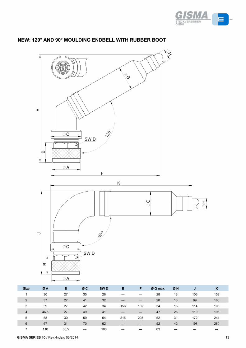
GISMA SERIES 10 / Rev.-Index: 05/2014 13
PLUG
Size Contact arrangement Ø A Ø B C D E F SW G
1 4 x 1 30 16.9 27 33.5 45,5 55 26
2 3 x 1.5 ; 7 x 1 37 19.9 27 33.5 44 56 32
3 7 x 1.5 ; 12 x 1 39 24 27 33.5 45 56 34
4 12 x 1.5 ; 19 x 1 46.5 28.5 27 33.5 45 55 41
5 24 x 1.5 ; 37 x 1 58 41 30 37.2 50,5 55 54
6 37 x 1.5 ; 61 x 1 67 48 31 37 50 56 62
7 4 x 10 110 77 66.5 78 138 153 100
71 4 x 10 120 105 104.5 154 184 223 110
ENDBELL
Size Contact arrangementstandard endbell large cable Ø endbell
max. cable Ø A 1max. cable Ø A B ca. C ca. D ca.
1 4 x 1 14 28 98 142 16 (see dimensions size 3)
2 3 x 1.5 ; 7 x 1 14 28 98 142 16 (see dimensions size 3)
3 7 x 1.5 ; 12 x 1 16 34 109 160 22 (see dimensions size 4)
4 12 x 1.5 ; 19 x 1 20 42 107 157 31 (see dimensions size 5)
5 24 x 1.5 ; 37 x 1 31 52 113 219 42 (dimensions on request)
6 37 x 1.5 ; 61 x 1 31 52 113 207 52 (dimensions on request)
7 4 x 10 57 83 229 342 ---
71 4 x 10 57 83 128 433 ---
12
NEW: 120° AND 90° MOULDING ENDBELL WITH RUBBER BOOT
Size Ø A B Ø C SW D E F Ø G max. Ø H J K
1 30 27 35 26 --- --- 28 13 106 158
2 37 27 41 32 --- --- 28 13 99 160
3 39 27 42 34 156 162 34 15 114 195
4 46,5 27 49 41 --- --- 47 25 119 196
5 58 30 59 54 215 203 52 31 172 244
6 67 31 70 62 --- --- 52 42 198 280
7 110 66,5 --- 100 --- --- 83 --- --- ---
13
A
SW D
J
C
90°
K
B
HG
A
120
°
SW D
F
B
E
C
G
H
NEW: 120° AND 90° MOULDING ENDBELL WITH RUBBER BOOT
Size Ø A B Ø C SW D E F Ø G max. Ø H J K
1 30 27 35 26 --- --- 28 13 106 158
2 37 27 41 32 --- --- 28 13 99 160
3 39 27 42 34 156 162 34 15 114 195
4 46,5 27 49 41 --- --- 47 25 119 196
5 58 30 59 54 215 203 52 31 172 244
6 67 31 70 62 --- --- 52 42 198 280
7 110 66,5 --- 100 --- --- 83 --- --- ---
13
13GISMA SERIES 10 / Rev.-Index: 01/2013
PLUG
Size Contact arrangement Ø A Ø B C D E F SW G
1 4 x 1 30 16.9 27 33.5 45,5 55 26
2 3 x 1.5 ; 7 x 1 37 19.9 27 33.5 44 56 32
3 7 x 1.5 ; 12 x 1 39 24 27 33.5 45 56 34
4 12 x 1.5 ; 19 x 1 46.5 28.5 27 33.5 45 55 41
5 24 x 1.5 ; 37 x 1 58 41 30 37.2 50,5 55 54
6 37 x 1.5 ; 61 x 1 67 48 31 37 50 56 62
7 4 x 10 110 77 66.5 78 138 153 100
71 4 x 10 120 105 104.5 154 184 223 110
ENDBELL
Size Contact arrangementstandard endbell large cable Ø endbell
max. cable Ø A 1max. cable Ø A B ca. C ca. D ca.
1 4 x 1 14 28 98 142 16 (see dimensions size 3)
2 3 x 1.5 ; 7 x 1 14 28 98 142 16 (see dimensions size 3)
3 7 x 1.5 ; 12 x 1 16 34 109 160 22 (see dimensions size 4)
4 12 x 1.5 ; 19 x 1 20 42 107 157 31 (see dimensions size 5)
5 24 x 1.5 ; 37 x 1 31 52 113 219 42 (dimensions on request)
6 37 x 1.5 ; 61 x 1 31 52 113 207 52 (dimensions on request)
7 4 x 10 57 83 229 342 ---
71 4 x 10 57 83 128 433 ---
12
NEW: 120° AND 90° MOULDING ENDBELL WITH RUBBER BOOT
Size Ø A B Ø C SW D E F Ø G max. Ø H J K
1 30 27 35 26 --- --- 28 13 106 158
2 37 27 41 32 --- --- 28 13 99 160
3 39 27 42 34 156 162 34 15 114 195
4 46,5 27 49 41 --- --- 47 25 119 196
5 58 30 59 54 215 203 52 31 172 244
6 67 31 70 62 --- --- 52 42 198 280
7 110 66,5 --- 100 --- --- 83 --- --- ---
13
A
SW D
J
C
90°
K
B
HG
A
120
°
SW D
F
B
E
C
G
H
NEW: 120° AND 90° MOULDING ENDBELL WITH RUBBER BOOT
Size Ø A B Ø C SW D E F Ø G max. Ø H J K
1 30 27 35 26 --- --- 28 13 106 158
2 37 27 41 32 --- --- 28 13 99 160
3 39 27 42 34 156 162 34 15 114 195
4 46,5 27 49 41 --- --- 47 25 119 196
5 58 30 59 54 215 203 52 31 172 244
6 67 31 70 62 --- --- 52 42 198 280
7 110 66,5 --- 100 --- --- 83 --- --- ---
13
13GISMA SERIES 10 / Rev.-Index: 01/2013
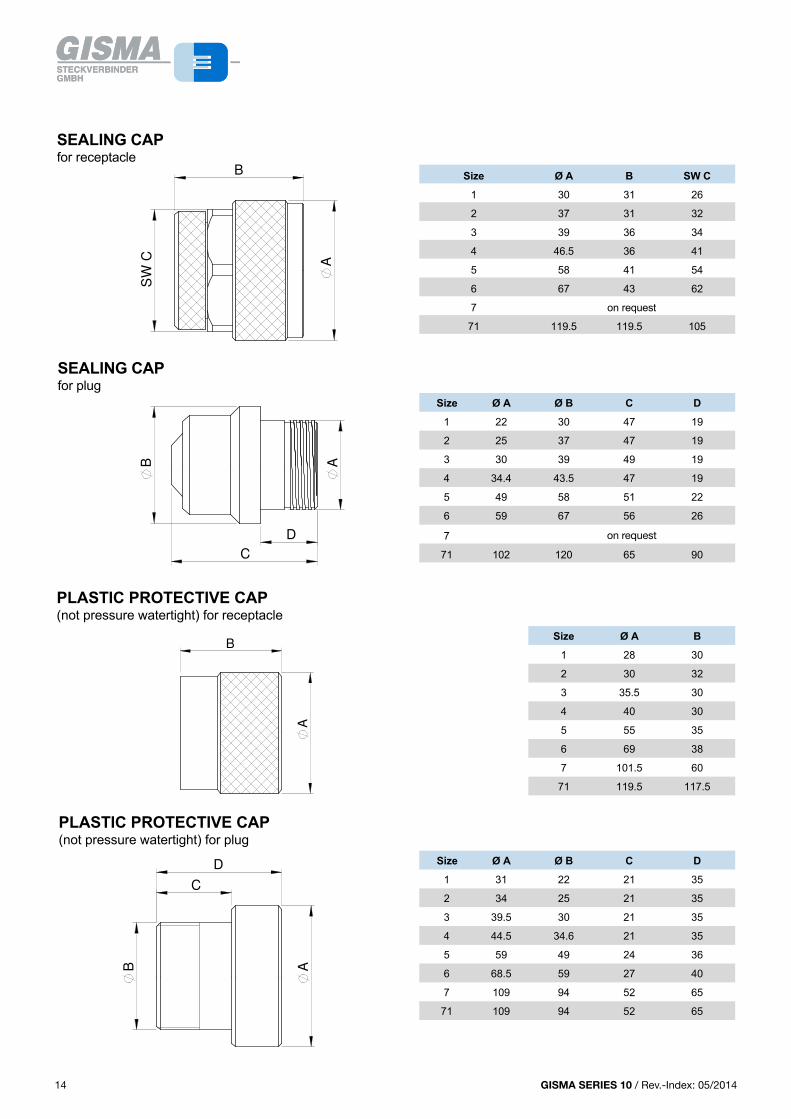
GISMA SERIES 10 / Rev.-Index: 05/201414
SHELL STYLES
5
COMPANY PROFILE
With more than 4000 different types, GISMA today is one of the leading manufactures of high-performance electrical and fibre optic and hybrid underwater and explosion proof connectors.
GISMA's success is based on:
1. A quality management system meeting the requirements of DIN ISO 9001 with DNV (Det Norske Veritas) certificate.
2. Consistency in meeting the needs of the customer.
3. Short and reliable delivery times.
4. Several services ranging from advising individual customers to the delivery of fully-tested, terminated and pressure tested cable assemblies.
Special orders are carried out quickly and efficiently using GISMA's own computer-aided design department, tooling and ultramodern computer controlled machines for production. With more than 95% of GISMA's production carried out in house, maximum flexibility is assured.
GISMA connectors are used world-wide in submarines, the offshore and chemical-, pump-, renewable industries and for underwater research. GISMA offers an extensive family of standard connectors with contact numbers from 1 - 265, voltages up to 11 kV and current ratings up to 1000 A in 18 different series.
All types of optical fibres, both single- and multi-mode, can be assembled with GISMA connectors.
Certificates of approval from well known test organisations such as TÜV (Technical Supervision Association), GL (German LLoyd), DNV (Det Norske Veritas) etc. are available at extra charge.
GISMA SERIES 10
The SERIES 10 described in this catalogue is designed for underwater operations down to 10.000 metres' depth. Thanks to the very high load capacity of the locking-screw thread, SERIES 10 is especially suitable for robust and frequent mating operations in the offshore industry. Except of those with high-voltage inserts (size 6 and 7), SERIES 10 connectors can be mated wet or underwater, up to a max. water-depth of 100 m. For underwater mating we recommend our fluid filled pressure balanced connectors SERIES 80. All SERIES 10 connectors can be exposed open-faced to water pressure.
With contact numbers from 3 - 61, current ratings up to 150 A and voltages up to 6.6 kV, the GISMA SERIES 10 comprises a wide range of high performance underwater electrical connectors.
At series 10 special designs are available on request
ATTENTION
Further documents have to be considered:
• Cabling instruction No.: Verkabelungsanleitung BR 10 BR 22 Stand 2010-48 (or newest version)• Handling instruction No.:HI-2007-001 (or newest version)
If series 10 connectors should be used for pressure balanced oil filled systems, please contact GISMA application engineering.
44 GISMA SERIES 10 / Rev.-Index: 01/2013
SEALING CAPfor receptacle
Size Ø A B SW C
1 30 31 26
2 37 31 32
3 39 36 34
4 46.5 36 41
5 58 41 54
6 67 43 62
7 on request
71 119.5 119.5 105
SEALING CAPfor plug
Size Ø A Ø B C D
1 22 30 47 19
2 25 37 47 19
3 30 39 49 19
4 34.4 43.5 47 19
5 49 58 51 22
6 59 67 56 26
7 94 109 52 65
71 102 120 65 90
PLASTIC PROTECTIVE CAP(not pressure watertight) for receptacle
Size Ø A B
1 28 30
2 30 32
3 35.5 30
4 40 30
5 55 35
6 69 38
7 101.5 60
71 119.5 117.5
PLASTIC PROTECTIVE CAP(not pressure watertight) for plug
Size Ø A Ø B C D
1 31 22 21 35
2 34 25 21 35
3 39.5 30 21 35
4 44.5 34.6 21 35
5 59 49 24 36
6 68.5 59 27 40
7 109 94 52 65
71 109 94 52 65
14
A
CS
W
B
SEALING CAPfor receptacle
Size Ø A B SW C
1 30 31 26
2 37 31 32
3 39 36 34
4 46.5 36 41
5 58 41 54
6 67 43 62
7 on request
71 119.5 119.5 105
SEALING CAPfor plug
Size Ø A Ø B C D
1 22 30 47 19
2 25 37 47 19
3 30 39 49 19
4 34.4 43.5 47 19
5 49 58 51 22
6 59 67 56 26
7 94 109 52 65
71 102 120 65 90
PLASTIC PROTECTIVE CAP(not pressure watertight) for receptacle
Size Ø A B
1 28 30
2 30 32
3 35.5 30
4 40 30
5 55 35
6 69 38
7 101.5 60
71 119.5 117.5
PLASTIC PROTECTIVE CAP(not pressure watertight) for plug
Size Ø A Ø B C D
1 31 22 21 35
2 34 25 21 35
3 39.5 30 21 35
4 44.5 34.6 21 35
5 59 49 24 36
6 68.5 59 27 40
7 109 94 52 65
71 109 94 52 65
14
B
D
C
A
D
A
C
B
A
B
KEYWAYS
Alternative orientations
To prevent cross coupling of connectors which have the same contact layout, four extra keyways are available.When ordering, please quote additional reference: for plugs and receptacles W, X, Y, Z.
SPACER
ORDERING INFORMATIONSee page 8
15
KEYWAYS
Alternative orientations
To prevent cross coupling of connectors which have the same contact layout, four extra keyways are available.When ordering, please quote additional reference: for plugs and receptacles W, X, Y, Z.
SPACER
ORDERING INFORMATIONSee page 8
15
KEYWAYS
Alternative orientations
To prevent cross coupling of connectors which have the same contact layout, four extra keyways are available.When ordering, please quote additional reference: for plugs and receptacles W, X, Y, Z.
SPACER
ORDERING INFORMATIONSee page 8
15
KEYWAYS
Alternative orientations
To prevent cross coupling of connectors which have the same contact layout, four extra keyways are available.When ordering, please quote additional reference: for plugs and receptacles W, X, Y, Z.
SPACER
ORDERING INFORMATIONSee page 8
15
14 GISMA SERIES 10 / Rev.-Index: 01/2013
on request
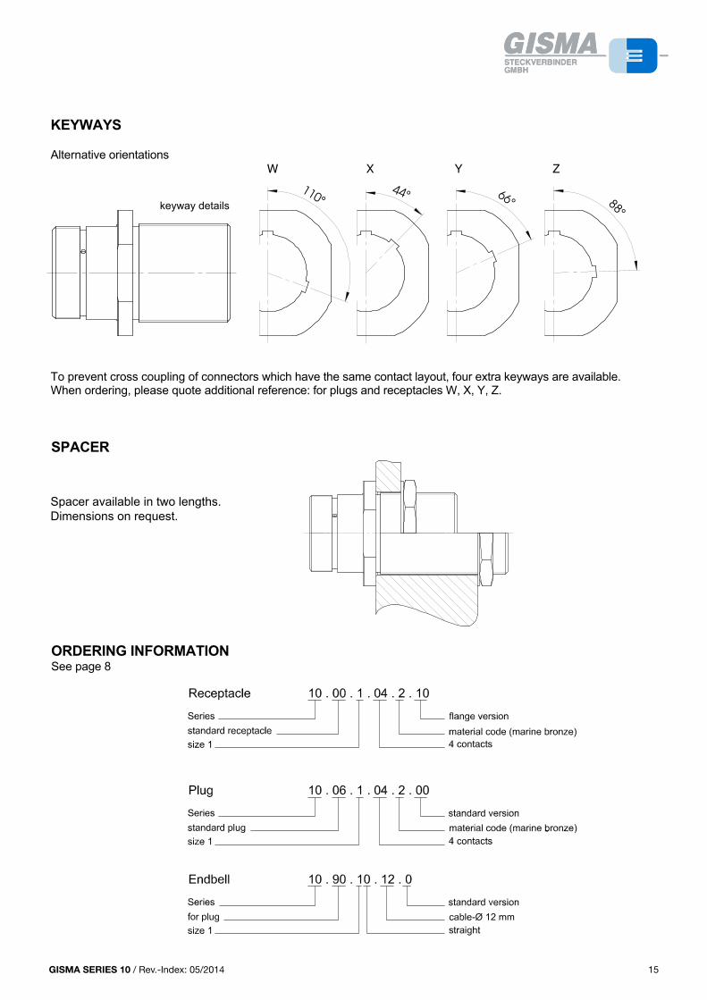
GISMA SERIES 10 / Rev.-Index: 05/2014 15
PLUG
Size Contact arrangement Ø A Ø B C D E F SW G
1 4 x 1 30 16.9 27 33.5 45,5 55 26
2 3 x 1.5 ; 7 x 1 37 19.9 27 33.5 44 56 32
3 7 x 1.5 ; 12 x 1 39 24 27 33.5 45 56 34
4 12 x 1.5 ; 19 x 1 46.5 28.5 27 33.5 45 55 41
5 24 x 1.5 ; 37 x 1 58 41 30 37.2 50,5 55 54
6 37 x 1.5 ; 61 x 1 67 48 31 37 50 56 62
7 4 x 10 110 77 66.5 78 138 153 100
71 4 x 10 120 105 104.5 154 184 223 110
ENDBELL
Size Contact arrangementstandard endbell large cable Ø endbell
max. cable Ø A 1max. cable Ø A B ca. C ca. D ca.
1 4 x 1 14 28 98 142 16 (see dimensions size 3)
2 3 x 1.5 ; 7 x 1 14 28 98 142 16 (see dimensions size 3)
3 7 x 1.5 ; 12 x 1 16 34 109 160 22 (see dimensions size 4)
4 12 x 1.5 ; 19 x 1 20 42 107 157 31 (see dimensions size 5)
5 24 x 1.5 ; 37 x 1 31 52 113 219 42 (dimensions on request)
6 37 x 1.5 ; 61 x 1 31 52 113 207 52 (dimensions on request)
7 4 x 10 57 83 229 342 ---
71 4 x 10 57 83 128 433 ---
12
NEW: 120° AND 90° MOULDING ENDBELL WITH RUBBER BOOT
Size Ø A B Ø C SW D E F Ø G max. Ø H J K
1 30 27 35 26 --- --- 28 13 106 158
2 37 27 41 32 --- --- 28 13 99 160
3 39 27 42 34 156 162 34 15 114 195
4 46,5 27 49 41 --- --- 47 25 119 196
5 58 30 59 54 215 203 52 31 172 244
6 67 31 70 62 --- --- 52 42 198 280
7 110 66,5 --- 100 --- --- 83 --- --- ---
13
A
SW D
J
C
90°
K
B
HG
A
120
°
SW D
F
B
E
C
G
H
NEW: 120° AND 90° MOULDING ENDBELL WITH RUBBER BOOT
Size Ø A B Ø C SW D E F Ø G max. Ø H J K
1 30 27 35 26 --- --- 28 13 106 158
2 37 27 41 32 --- --- 28 13 99 160
3 39 27 42 34 156 162 34 15 114 195
4 46,5 27 49 41 --- --- 47 25 119 196
5 58 30 59 54 215 203 52 31 172 244
6 67 31 70 62 --- --- 52 42 198 280
7 110 66,5 --- 100 --- --- 83 --- --- ---
13
13GISMA SERIES 10 / Rev.-Index: 01/2013
SEALING CAPfor receptacle
Size Ø A B SW C
1 30 31 26
2 37 31 32
3 39 36 34
4 46.5 36 41
5 58 41 54
6 67 43 62
7 on request
71 119.5 119.5 105
SEALING CAPfor plug
Size Ø A Ø B C D
1 22 30 47 19
2 25 37 47 19
3 30 39 49 19
4 34.4 43.5 47 19
5 49 58 51 22
6 59 67 56 26
7 94 109 52 65
71 102 120 65 90
PLASTIC PROTECTIVE CAP(not pressure watertight) for receptacle
Size Ø A B
1 28 30
2 30 32
3 35.5 30
4 40 30
5 55 35
6 69 38
7 101.5 60
71 119.5 117.5
PLASTIC PROTECTIVE CAP(not pressure watertight) for plug
Size Ø A Ø B C D
1 31 22 21 35
2 34 25 21 35
3 39.5 30 21 35
4 44.5 34.6 21 35
5 59 49 24 36
6 68.5 59 27 40
7 109 94 52 65
71 109 94 52 65
14
88°
66°
44°110°
keyway details X YW Z
keyway details
KEYWAYS
Alternative orientations
To prevent cross coupling of connectors which have the same contact layout, four extra keyways are available.When ordering, please quote additional reference: for plugs and receptacles W, X, Y, Z.
SPACER
ORDERING INFORMATIONSee page 8
15
KEYWAYS
Alternative orientations
To prevent cross coupling of connectors which have the same contact layout, four extra keyways are available.When ordering, please quote additional reference: for plugs and receptacles W, X, Y, Z.
SPACER
ORDERING INFORMATIONSee page 8
15
KEYWAYS
Alternative orientations
To prevent cross coupling of connectors which have the same contact layout, four extra keyways are available.When ordering, please quote additional reference: for plugs and receptacles W, X, Y, Z.
SPACER
ORDERING INFORMATIONSee page 8
15
KEYWAYS
Alternative orientations
To prevent cross coupling of connectors which have the same contact layout, four extra keyways are available.When ordering, please quote additional reference: for plugs and receptacles W, X, Y, Z.
SPACER
ORDERING INFORMATIONSee page 8
15
Spacer available in two lengths.Dimensions on request.
15GISMA SERIES 10 / Rev.-Index: 01/2013
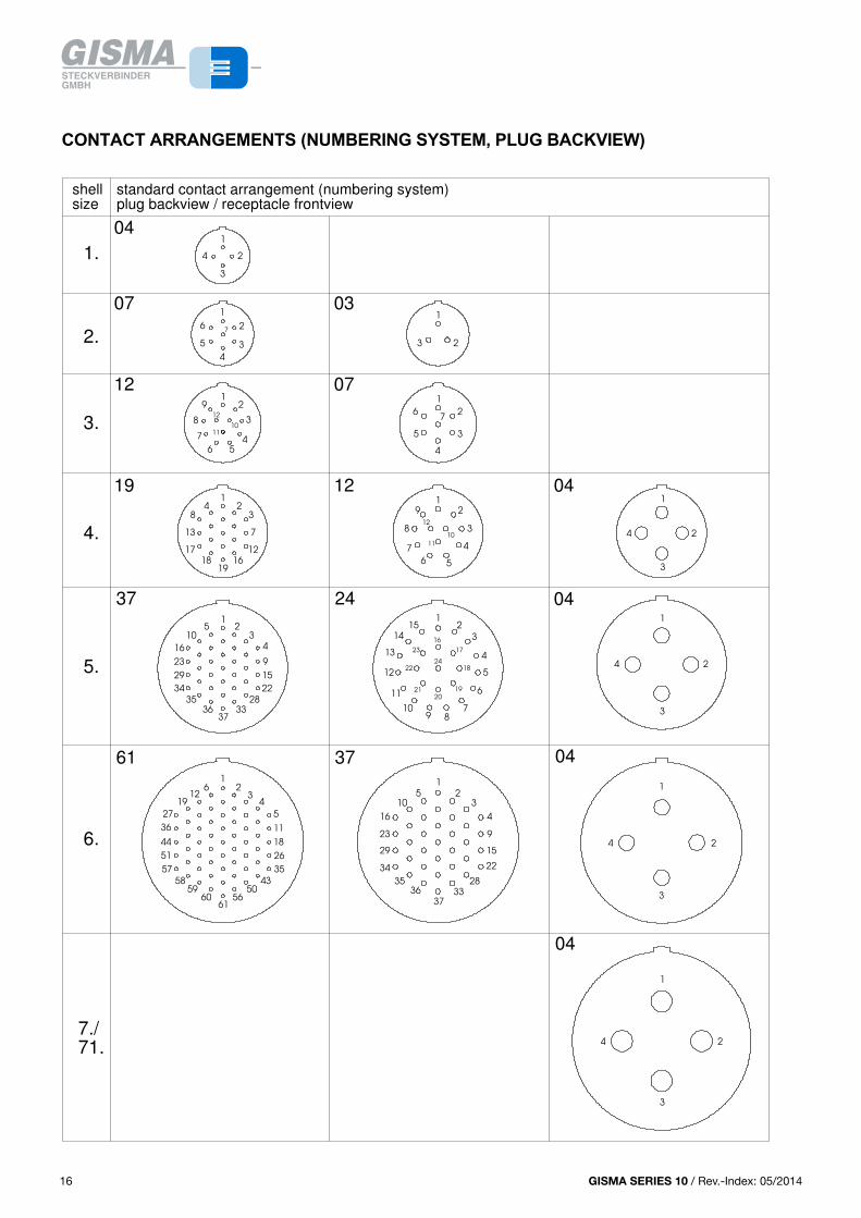
GISMA SERIES 10 / Rev.-Index: 05/201416
SHELL STYLES
5
COMPANY PROFILE
With more than 4000 different types, GISMA today is one of the leading manufactures of high-performance electrical and fibre optic and hybrid underwater and explosion proof connectors.
GISMA's success is based on:
1. A quality management system meeting the requirements of DIN ISO 9001 with DNV (Det Norske Veritas) certificate.
2. Consistency in meeting the needs of the customer.
3. Short and reliable delivery times.
4. Several services ranging from advising individual customers to the delivery of fully-tested, terminated and pressure tested cable assemblies.
Special orders are carried out quickly and efficiently using GISMA's own computer-aided design department, tooling and ultramodern computer controlled machines for production. With more than 95% of GISMA's production carried out in house, maximum flexibility is assured.
GISMA connectors are used world-wide in submarines, the offshore and chemical-, pump-, renewable industries and for underwater research. GISMA offers an extensive family of standard connectors with contact numbers from 1 - 265, voltages up to 11 kV and current ratings up to 1000 A in 18 different series.
All types of optical fibres, both single- and multi-mode, can be assembled with GISMA connectors.
Certificates of approval from well known test organisations such as TÜV (Technical Supervision Association), GL (German LLoyd), DNV (Det Norske Veritas) etc. are available at extra charge.
GISMA SERIES 10
The SERIES 10 described in this catalogue is designed for underwater operations down to 10.000 metres' depth. Thanks to the very high load capacity of the locking-screw thread, SERIES 10 is especially suitable for robust and frequent mating operations in the offshore industry. Except of those with high-voltage inserts (size 6 and 7), SERIES 10 connectors can be mated wet or underwater, up to a max. water-depth of 100 m. For underwater mating we recommend our fluid filled pressure balanced connectors SERIES 80. All SERIES 10 connectors can be exposed open-faced to water pressure.
With contact numbers from 3 - 61, current ratings up to 150 A and voltages up to 6.6 kV, the GISMA SERIES 10 comprises a wide range of high performance underwater electrical connectors.
At series 10 special designs are available on request
ATTENTION
Further documents have to be considered:
• Cabling instruction No.: Verkabelungsanleitung BR 10 BR 22 Stand 2010-48 (or newest version)• Handling instruction No.:HI-2007-001 (or newest version)
If series 10 connectors should be used for pressure balanced oil filled systems, please contact GISMA application engineering.
44 GISMA SERIES 10 / Rev.-Index: 01/2013
CONTACT ARRANGEMENTS (NUMBERING SYSTEM, RECEPTACLE BACKVIEW)
17
CONTACT ARRANGEMENTS (NUMBERING SYSTEM, PLUG BACKVIEW)
16
12 04
07
07 03
04
19
121
standard contact arrangement (numbering system)plug backview / receptacle frontview
2.
1.
shell size
04
3.
4.
5.
6.
7./71.
1
2
3
4
1
6
3
4
5
27
1
23
6
38
9
10
711
1
2
4
5
12
1
2
3
4
35
36 3337
34
10
37
16
61 37
12
3
4
9
15
22
28
24
29
23
5
6
7
8
9
10
11
12
3
4
5
12 6 2
3
4
5
7
16
3
18
17
13
8
1
19
2
7
12
4
1
2
3
4
51
36 11
27
19
50
1
23
4
5
12
18
26
35
43
44
5661
6059
58
57
6
35
10
29
23
16
15
1
2
3
4
9
34 22
28
33
37
36
5
18
1
1921
22
23
20
2
3
4
5
6
7
8910
11
12
13
14
15
16
17
24
3
2
1
04
04
4
1
2
3
4
16 GISMA SERIES 10 / Rev.-Index: 01/2013
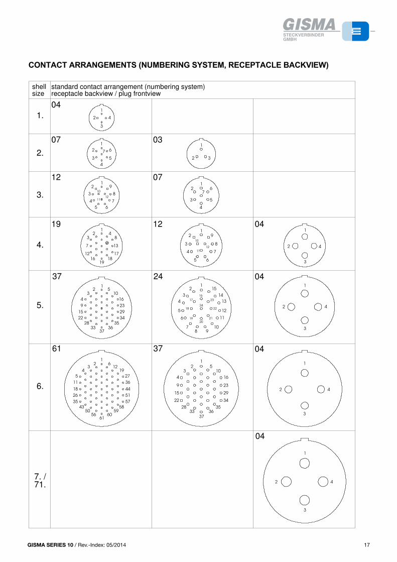
GISMA SERIES 10 / Rev.-Index: 05/2014 17
PLUG
Size Contact arrangement Ø A Ø B C D E F SW G
1 4 x 1 30 16.9 27 33.5 45,5 55 26
2 3 x 1.5 ; 7 x 1 37 19.9 27 33.5 44 56 32
3 7 x 1.5 ; 12 x 1 39 24 27 33.5 45 56 34
4 12 x 1.5 ; 19 x 1 46.5 28.5 27 33.5 45 55 41
5 24 x 1.5 ; 37 x 1 58 41 30 37.2 50,5 55 54
6 37 x 1.5 ; 61 x 1 67 48 31 37 50 56 62
7 4 x 10 110 77 66.5 78 138 153 100
71 4 x 10 120 105 104.5 154 184 223 110
ENDBELL
Size Contact arrangementstandard endbell large cable Ø endbell
max. cable Ø A 1max. cable Ø A B ca. C ca. D ca.
1 4 x 1 14 28 98 142 16 (see dimensions size 3)
2 3 x 1.5 ; 7 x 1 14 28 98 142 16 (see dimensions size 3)
3 7 x 1.5 ; 12 x 1 16 34 109 160 22 (see dimensions size 4)
4 12 x 1.5 ; 19 x 1 20 42 107 157 31 (see dimensions size 5)
5 24 x 1.5 ; 37 x 1 31 52 113 219 42 (dimensions on request)
6 37 x 1.5 ; 61 x 1 31 52 113 207 52 (dimensions on request)
7 4 x 10 57 83 229 342 ---
71 4 x 10 57 83 128 433 ---
12
NEW: 120° AND 90° MOULDING ENDBELL WITH RUBBER BOOT
Size Ø A B Ø C SW D E F Ø G max. Ø H J K
1 30 27 35 26 --- --- 28 13 106 158
2 37 27 41 32 --- --- 28 13 99 160
3 39 27 42 34 156 162 34 15 114 195
4 46,5 27 49 41 --- --- 47 25 119 196
5 58 30 59 54 215 203 52 31 172 244
6 67 31 70 62 --- --- 52 42 198 280
7 110 66,5 --- 100 --- --- 83 --- --- ---
13
A
SW D
J
C
90°
K
B
HG
A
120
°
SW D
F
B
E
C
G
H
NEW: 120° AND 90° MOULDING ENDBELL WITH RUBBER BOOT
Size Ø A B Ø C SW D E F Ø G max. Ø H J K
1 30 27 35 26 --- --- 28 13 106 158
2 37 27 41 32 --- --- 28 13 99 160
3 39 27 42 34 156 162 34 15 114 195
4 46,5 27 49 41 --- --- 47 25 119 196
5 58 30 59 54 215 203 52 31 172 244
6 67 31 70 62 --- --- 52 42 198 280
7 110 66,5 --- 100 --- --- 83 --- --- ---
13
13GISMA SERIES 10 / Rev.-Index: 01/2013
CONTACT ARRANGEMENTS (NUMBERING SYSTEM, RECEPTACLE BACKVIEW)
17
CONTACT ARRANGEMENTS (NUMBERING SYSTEM, PLUG BACKVIEW)
16
19
8
18
3
17
21
16
137
12
4
8
2
6
9
10
11
1
7
3
4
5
12
1
2
3
4
0712
04
19 04
03
12
04
1
3.
2.
1.
shell size
standard contact arrangement (numbering system)receptacle backview / plug frontview
07
4.
5.
6.
7./71.
2
1
3
4
1
53
4
2 67
1
2 3
8
7
6
9
10
11
12
3
4
5
12
4
2
3
6
5
7
24
36
35
1
16
37
23
3761
28
37
2
3
4
9
15
22
33
29
34
10
5
3
1
2 4
51
44
27
36
57
1912
1
23
4
5
11
18
26
35
4350
5661
6059
58
6
1
2
3
4
2
21
20
4
22
23
1
3
18
19
5
6
7
8 9
10
11
12
13
14
15
16
17
24
2
34
29
23
16
10
1
35
3
4
9
15
22
28
33
37
36
5
2
1
3
04
04
4
17GISMA SERIES 10 / Rev.-Index: 01/2013
shell
19
07
04
12
2.
6.
04
receptacle backview / plug frontview
12 04
4.
5.
03
1
standard contact arrangement (numbering system)
1.
07
size
3.
7. /71.
3
1
2 4
1
3
6
4
2
5
7
2
1
3
711
8
12
5
4
6
10
3
9
12
5
4
62
3
7
17
19
12
1
3
2
8
7
16
13
18
4
711
3
2
1
4
10
9
5 6
812 2
1
3
4
36
24
16
37
28
37
37
12
3
4
9
61
22
15
23
33
29
35
34
105
2
3
1
4
27
1912
12
34
5
11
18
26
35
4350
5661
6059
58
57
51
44
36
6
23
16
10
1
2
3
4
9
15
22
28
33
37
36
35
34
29
5
04
1
3
2
04
4
2
3
1
4
21
15
12
3
13
16
4
5
6
78
10
11
23
22
14
20
12
17
18
19
9
24

GISMA Steckverbinder GmbHLeinestr. 25D-24539 NeumünsterTel. +49 - 43 21 - 98 35 - 30 Fax +49 - 43 21 - 98 35 - 55http://www.gisma-connectors.deE-Mail: [email protected]
Don´t hesitate to contact us for more technical details.
Für ausführliche technische Informationen stehen wir gerne jederzeit zur Verfügung