Embed Size (px)
Citation preview
November 2008
Encoders for
Servo Drives
November 2007
Drehgeber
September 2007
Winkelmessgeräte
ohne Eigenlagerung
März 2006
Produktinformation
ERM 200Magnetische Einbau-Messgeräte
Mai 2007
Offene
Längenmessgeräte
Juni 2007
Längenmessgerätefür gesteuerte Werkzeug-maschinen
Juni 2006
Winkelmessgeräte
mit Eigenlagerung
This catalog supersedes all previous editions, which thereby become invalid.The basis for ordering from HEIDENHAIN is always the catalog edition valid when the contract is made.
Standards (ISO, EN, etc.) apply only where explicitly stated in the catalog.
This catalog is not intended as an overview of the HEIDENHAIN product program. Rather it presents a selection of encoders
for use on servo drives.
In the selection tables you will fi nd an overview of all HEIDENHAIN encoders for use on electric drives and the most important specifi cations. The descriptions of the technical features contain fundamental information on the use of rotary, angle, and linear encoders on electric drives.
The mounting information and the detailed specifi cations refer to the rotary
encoders developed specifi cally for drive technology. Other rotary encoders are described in the other product catalogs.
For the linear and angle encoders listed in the selection tables, you will fi nd detailed information such as mounting information, specifi cations and dimensions in the respective product
catalogs.
Further Product Catalogs
CatalogRotary Encoders
Contents:Incremental Rotary EncodersERN, ROD
Absolute Rotary EncodersECN, EQN, ROC, ROQ
CatalogAngle Encoders with Integral Bearing
Contents:Incremental Angle EncodersRON, RPN, ROD
Absolute Angle EncodersRCN
Product InformationERM 200
Contents:Incremental Modular Magnetic Encoders
CatalogExposed Linear Encoders
Contents: Incremental Linear EncodersLIP, PP, LIF, LIDA
CatalogLinear Encoders
for Numerically Controlled Machine ToolsContents:Incremental Linear EncodersLB, LF, LS
Absolute Linear EncodersLC
CatalogAngle Encoders without Integral Bearing
Contents:Incremental Angle EncodersERA, ERP
Overview
Explanation of the Selection Tables 6
Rotary Encoders for Mounting on Motors 8
Rotary Encoders for Integration in Motors 10
Angle Encoders and Rotary Encoders for Integrated and Hollow-Shaft Motors 12
Exposed Linear Encoders for Linear Drives 14
Sealed Linear Encoders for Linear Drives 16
Technical Features and Mounting Information
Rotary Encoders and Angle Encoders for Three-Phase AC and DC Motors 18
Linear Encoders for Linear Drives 20
Measuring Principles 22
Measuring Accuracy 25
Mechanical Designs,
Mounting and
Accessories
Rotary Encoders with Integral Bearing and Stator Coupling 28
Rotary Encoders without Integral Bearing 30
Aligning the Rotary Encoders to the Motor EMF 33
General Mechanical Information 34
Specifi cations
Rotary Encoders with
Integral Bearing
ECN/EQN 1100 Series 36
ERN 1100 Series 38
ECN/EQN 1300 Series 40
ERN 1300 Series 42
Rotary Encoders
without Integral
Bearing
ECI/EQI 1100 Series 44
ECI/EQI 1300 Series 46
ERO 1200 Series 48
ERO 1300 Series 50
ERO 1400 Series 52
Angle Encoders See catalog: Angle Encoders
Linear encoders See catalogs: Exposed Linear Encodersand Linear Encoders for Numerically Controlled Machine Tools
Electrical Connection
Interfaces Incremental Signals 54
Commutation Signals 58
EnDat Absolute Position Values 60
Connecting Elements and Cables 67
General Electrical Information 71
HEIDENHAIN Measuring and Testing Devices and Evaluation Electronics 74
Table of Contents
4
Encoders for Servo Drives
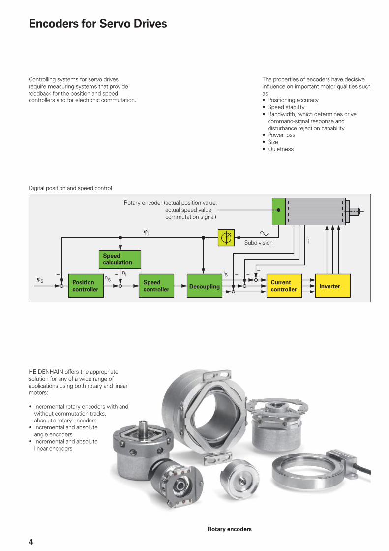
Controlling systems for servo drives require measuring systems that provide feedback for the position and speed controllers and for electronic commutation.
The properties of encoders have decisive infl uence on important motor qualities such as:
Positioning accuracySpeed stabilityBandwidth, which determines drive command-signal response and disturbance rejection capabilityPower lossSizeQuietness
•••
•••
Digital position and speed control
Position
controller
Speed
controllerDecoupling Inverter
Current
controller
Speed
calculation
Subdivision
Rotary encoder ( actual position value,actual speed value,commutation signal)
HEIDENHAIN offers the appropriate solution for any of a wide range of applications using both rotary and linear motors:
Incremental rotary encoders with and without commutation tracks, absolute rotary encodersIncremental and absolute angle encodersIncremental and absolute linear encoders
•
•
•
Rotary encoders
5
Rotary encoder
Angle encoders
Motor for “digital” drive systems (digital position and speed control)
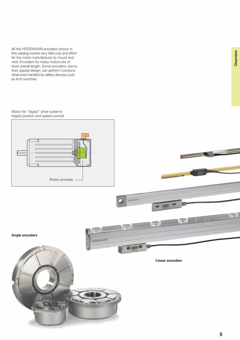
All the HEIDENHAIN encoders shown in this catalog involve very little cost and effort for the motor manufacturer to mount and wire. Encoders for rotary motors are of short overall length. Some encoders, due to their special design, can perform functions otherwise handled by safety devices such as limit switches.
Linear encoders
Overv
iew
6
Explanation of the Selection Tables
The tables on the following pages list the encoders suited for individual motor designs. The encoders are available with dimensions and output signals to fi t specifi c types of motors (dc or ac).
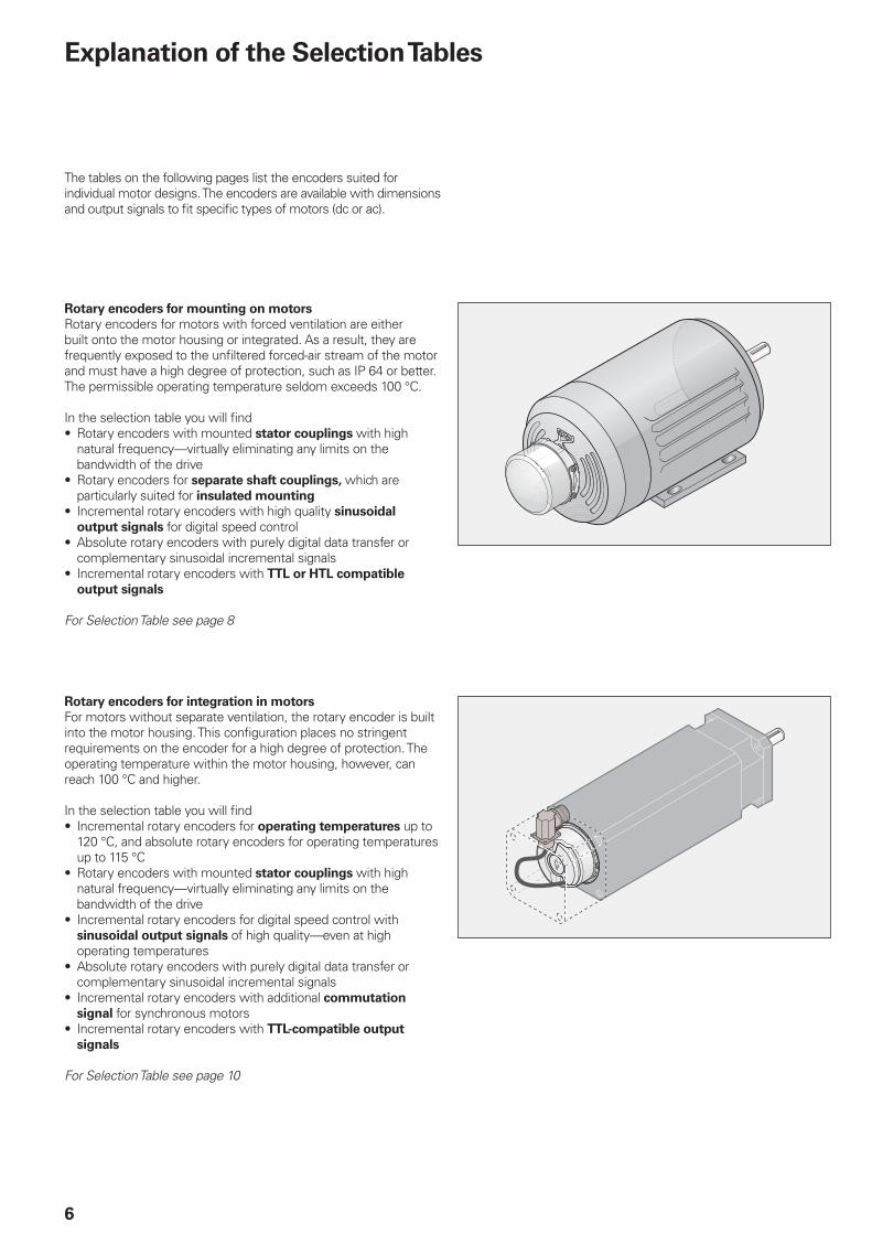
Rotary encoders for mounting on motors
Rotary encoders for motors with forced ventilation are either built onto the motor housing or integrated. As a result, they are frequently exposed to the unfi ltered forced-air stream of the motor and must have a high degree of protection, such as IP 64 or better. The permissible operating temperature seldom exceeds 100 °C.
In the selection table you will fi ndRotary encoders with mounted stator couplings with high natural frequency—virtually eliminating any limits on the bandwidth of the driveRotary encoders for separate shaft couplings, which are particularly suited for insulated mounting
Incremental rotary encoders with high quality sinusoidal
output signals for digital speed controlAbsolute rotary encoders with purely digital data transfer or complementary sinusoidal incremental signalsIncremental rotary encoders with TTL or HTL compatible
output signals
For Selection Table see page 8
•
•
•
•
•
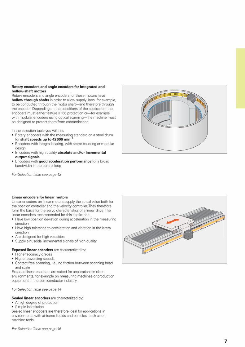
Rotary encoders for integration in motors
For motors without separate ventilation, the rotary encoder is built into the motor housing. This confi guration places no stringent requirements on the encoder for a high degree of protection. The operating temperature within the motor housing, however, can reach 100 °C and higher.
In the selection table you will fi ndIncremental rotary encoders for operating temperatures up to 120 °C, and absolute rotary encoders for operating temperatures up to 115 °CRotary encoders with mounted stator couplings with high natural frequency—virtually eliminating any limits on the bandwidth of the driveIncremental rotary encoders for digital speed control with sinusoidal output signals of high quality—even at high operating temperaturesAbsolute rotary encoders with purely digital data transfer or complementary sinusoidal incremental signalsIncremental rotary encoders with additional commutation
signal for synchronous motorsIncremental rotary encoders with TTL-compatible output
signals
For Selection Table see page 10
•
•
•
•
•
•
7
Rotary encoders and angle encoders for integrated and
hollow-shaft motors
Rotary encoders and angle encoders for these motors have hollow through shafts in order to allow supply lines, for example, to be conducted through the motor shaft—and therefore through the encoder. Depending on the conditions of the application, the encoders must either feature IP 66 protection or—for example with modular encoders using optical scanning—the machine must be designed to protect them from contamination.
In the selection table you will fi ndRotary encoders with the measuring standard on a steel drum for shaft speeds up to 42 000 min
–1
Encoders with integral bearing, with stator coupling or modular designEncoders with high quality absolute and/or incremental
output signals
Encoders with good acceleration performance for a broad bandwidth in the control loop
For Selection Table see page 12
•
•
•
•
Linear encoders for linear motors
Linear encoders on linear motors supply the actual value both for the position controller and the velocity controller. They therefore form the basis for the servo characteristics of a linear drive. The linear encoders recommended for this application:
Have low position deviation during acceleration in the measuring directionHave high tolerance to acceleration and vibration in the lateral directionAre designed for high velocitiesSupply sinusoidal incremental signals of high quality
Exposed linear encoders are characterized by:Higher accuracy gradesHigher traversing speedsContact-free scanning, i.e., no friction between scanning head and scale
Exposed linear encoders are suited for applications in clean environments, for example on measuring machines or production equipment in the semiconductor industry.
For Selection Table see page 14
Sealed linear encoders are characterized by:A high degree of protectionSimple installation
Sealed linear encoders are therefore ideal for applications in environments with airborne liquids and particles, such as on machine tools.
For Selection Table see page 16
•
•
••
•••
••
8
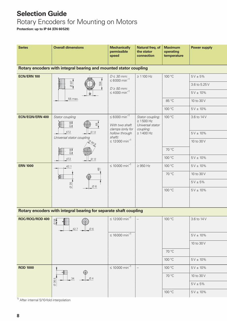
Selection Guide
Rotary Encoders for Mounting on MotorsProtection: up to IP 64 (EN 60 529)
Series Overall dimensions Mechanically
permissible
speed
Natural freq. of
the stator
connection
Maximum
operating
temperature
Power supply
Rotary encoders with integral bearing and mounted stator coupling
ECN/ERN 100 D † 30 mm:† 6 000 min–1
D ‡ 50 mm:† 4 000 min–1
‡ 1 100 Hz 100 °C 5 V ± 5%
3.6 to 5.25 V
5 V ± 10%
85 °C 10 to 30 V
100 °C 5 V ± 10%
ECN/EQN/ERN 400 Stator coupling † 6 000 min–1
With two shaft clamps (only for hollow through shaft): † 12 000 min–1
Stator coupling:‡ 1 500 HzUniversal stator coupling:‡ 1 400 Hz
100 °C 3.6 to 14 V
5 V ± 10%
10 to 30 V
70 °C
100 °C 5 V ± 10%
ERN 1000 † 10 000 min–1 ‡ 950 Hz 100 °C 5 V ± 10%
70 °C 10 to 30 V
5 V ± 5%
100 °C 5 V ± 10%
Rotary encoders with integral bearing for separate shaft coupling
ROC/ROQ/ROD 400 † 12 000 min–1 – 100 °C 3.6 to 14 V
† 16 000 min–1 5 V ± 10%
10 to 30 V
70 °C
100 °C 5 V ± 10%
ROD 1000 † 10 000 min–1 – 100 °C 5 V ± 10%
70 °C 10 to 30 V
5 V ± 5%
100 °C 5 V ± 10%
1) After internal 5/10-fold interpolation
Universal stator coupling
��
9
Incremental signals Absolute position values Model For more
information
Output signals Signal periods per
revolution
Positions per
revolution
Distinguishable
revolutions
Data interface
» 1 VPP 2 048 8 192 – EnDat 2.2 / 01 ECN 113 Catalog:
Rotary
Encoders– – 33 554 432 EnDat 2.2 / 22 ECN 125
« TTL 1 000 to 5 000 – ERN 120
« HTL ERN 130
» 1 VPP ERN 180
» 1 VPP 512, 2 048 8 192 – / 4 096 EnDat 2.2 / 01 ECN 413 / EQN 425
– – 33 554 432 EnDat 2.2 / 22 ECN 425/EQN 437
« TTL 250 to 5 000 – ERN 420
« HTL ERN 430
« TTL ERN 460
» 1 VPP 1 000 to 5 000 ERN 480
« TTL 100 to 3 600 – ERN 1020
« HTL ERN 1030
« TTL 5 000 to 36 0001)ERN 1070
» 1 VPP 100 to 3 600 ERN 1080
512, 2 048 Z1 track for sine commutation ERN 1085 Product
Information
» 1 VPP 512, 2 048 8 192 – / 4 096 EnDat 2.2 / 01 ROC 413/ROQ 425 Catalog:
Rotary
Encoders– – 33 554 432 EnDat 2.2 / 22 ROC 425/ROQ 437
« TTL 50 to 10 000 – ROD 426
« HTL 50 to 5 000 ROD 436
« TTL 50 to 10 000 ROD 466
» 1 VPP 1 000 to 5 000 ROD 486
« TTL 100 to 3 600 – ROD 1020
« HTL ROD 1030
« TTL 5 000 to 36 0001)ROD 1070
» 1 VPP 100 to 3 600 ROD 1080
10
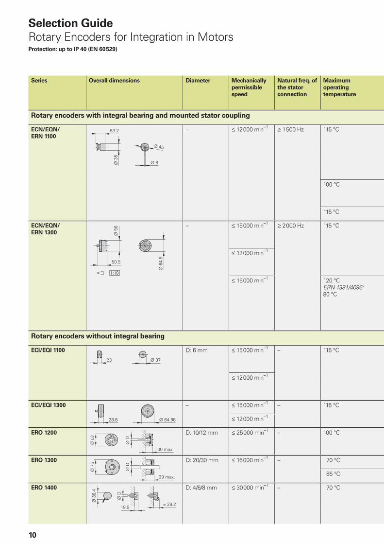
Selection Guide
Rotary Encoders for Integration in MotorsProtection: up to IP 40 (EN 60 529)
Series Overall dimensions Diameter Mechanically
permissible
speed
Natural freq. of
the stator
connection
Maximum
operating
temperature
Rotary encoders with integral bearing and mounted stator coupling
ECN/EQN/
ERN 1100
– † 12 000 min–1 ‡ 1 500 Hz 115 °C
100 °C
115 °C
ECN/EQN/
ERN 1300
– † 15 000 min–1 ‡ 2 000 Hz 115 °C
† 12 000 min–1
† 15 000 min–1 120 °CERN 1381/4096:80 °C
Rotary encoders without integral bearing
ECI/EQI 1100 D: 6 mm † 15 000 min–1 – 115 °C
† 12 000 min–1
ECI/EQI 1300 – † 15 000 min–1 – 115 °C
† 12 000 min–1
ERO 1200 D: 10/12 mm † 25 000 min–1 – 100 °C
ERO 1300 D: 20/30 mm † 16 000 min–1 – 70 °C
85 °C
ERO 1400 D: 4/6/8 mm † 30 000 min–1 – 70 °C
����
����
����
����
�� ���
���
11
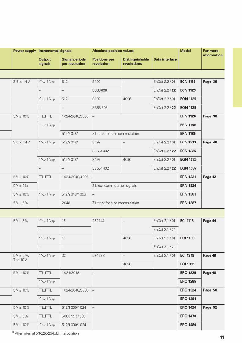
Power supply Incremental signals Absolute position values Model For more
information
Output
signals
Signal periods
per revolution
Positions per
revolution
Distinguishable
revolutions
Data interface
3.6 to 14 V » 1 VPP 512 8 192 – EnDat 2.2 / 01 ECN 1113 Page 36
– – 8 388 608 EnDat 2.2 / 22 ECN 1123
» 1 VPP 512 8 192 4 096 EnDat 2.2 / 01 EQN 1125
– – 8 388 608 EnDat 2.2 / 22 EQN 1135
5 V ± 10% « TTL 1 024/2 048/3 600 – ERN 1120 Page 38
» 1 VPP ERN 1180
512/2 048/ Z1 track for sine commutation ERN 1185
3.6 to 14 V » 1 VPP 512/2 048/ 8 192 – EnDat 2.2 / 01 ECN 1313 Page 40
– – 33 554 432 EnDat 2.2 / 22 ECN 1325
» 1 VPP 512/2 048/ 8 192 4 096 EnDat 2.2 / 01 EQN 1325
– – 33 554 432 EnDat 2.2 / 22 EQN 1337
5 V ± 10% « TTL 1 024/2 048/4 096 – ERN 1321 Page 42
5 V ± 5% 3 block commutation signals ERN 1326
5 V ± 10% » 1 VPP 512/2 048/4 096 – ERN 1381
5 V ± 5% 2 048 Z1 track for sine commutation ERN 1387
5 V ± 5% » 1 VPP 16 262 144 – EnDat 2.1 / 01 ECI 1118 Page 44
– – EnDat 2.1 / 21
» 1 VPP 16 4 096 EnDat 2.1 / 01 EQI 1130
– – EnDat 2.1 / 21
5 V ± 5 %/7 to 10 V
» 1 VPP 32 524 288 – EnDat 2.1 / 01 ECI 1319 Page 46
4 096 EQI 1331
5 V ± 10% « TTL 1 024/2 048 – ERO 1225 Page 48
» 1 VPP ERO 1285
5 V ± 10% « TTL 1 024/2 048/5 000 – ERO 1324 Page 50
» 1 VPP ERO 1384
5 V ± 10% « TTL 512/1 000/1 024 – ERO 1420 Page 52
5 V ± 5% « TTL 5 000 to 37 5001)ERO 1470
5 V ± 10% » 1 VPP 512/1 000/1 024 ERO 1480
1) After internal 5/10/20/25-fold interpolation
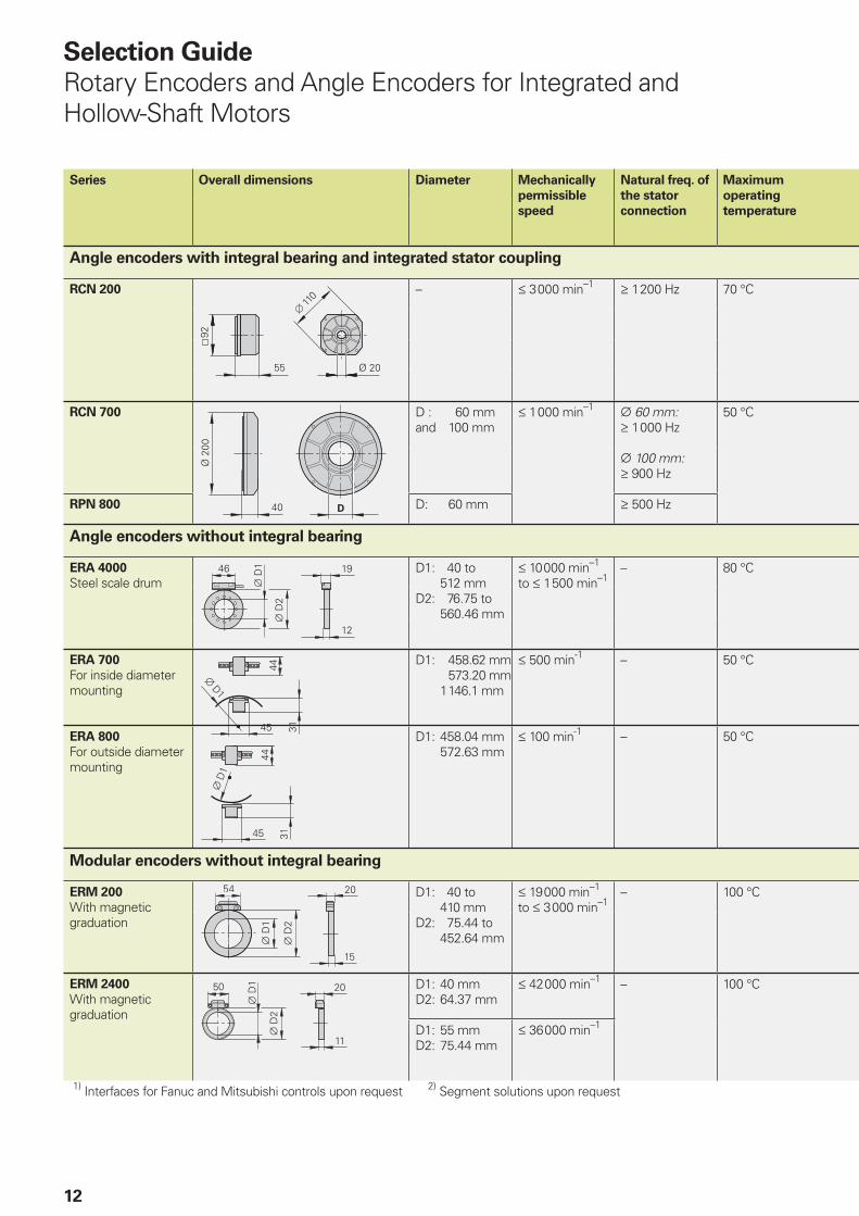
12
Series Overall dimensions Diameter Mechanically
permissible
speed
Natural freq. of
the stator
connection
Maximum
operating
temperature
Angle encoders with integral bearing and integrated stator coupling
RCN 200 – † 3 000 min–1 ‡ 1 200 Hz 70 °C
RCN 700 D : 60 mmand 100 mm
† 1 000 min–1 ¬ 60 mm:‡ 1 000 Hz
¬ 100 mm:‡ 900 Hz
50 °C
RPN 800 D: 60 mm ‡ 500 Hz
Angle encoders without integral bearing
ERA 4000
Steel scale drum D1: 40 to
512 mmD2: 76.75 to 560.46 mm
† 10 000 min–1 to † 1 500 min–1
– 80 °C
ERA 700
For inside diameter mounting
D1: 458.62 mm 573.20 mm 1 146.1 mm
† 500 min-1 – 50 °C
ERA 800
For outside diameter mounting
D1: 458.04 mm 572.63 mm
† 100 min-1 – 50 °C
Modular encoders without integral bearing
ERM 200
With magnetic graduation
D1: 40 to 410 mmD2: 75.44 to 452.64 mm
† 19 000 min–1 to † 3 000 min–1
– 100 °C
ERM 2400
With magnetic graduation
D1: 40 mmD2: 64.37 mm
† 42 000 min–1 – 100 °C
D1: 55 mmD2: 75.44 mm
† 36 000 min–1
1) Interfaces for Fanuc and Mitsubishi controls upon request 2) Segment solutions upon request
Selection Guide
Rotary Encoders and Angle Encoders for Integrated and Hollow-Shaft Motors
�
13
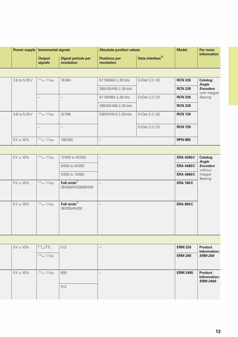
Power supply Incremental signals Absolute position values Model For more
information
Output
signals
Signal periods per
revolution
Positions per
revolution
Data interface1)
3.6 to 5.25 V » 1 VPP 16 384 67 108 864 ƒ 26 bits EnDat 2.2 / 02 RCN 226 Catalog:
Angle
Encoders
with Integral Bearing
268 435 456 ƒ 28 bits RCN 228
– – 67 108 864 ƒ 26 bits EnDat 2.2 / 22 RCN 226
268 435 456 ƒ 28 bits RCN 228
3.6 to 5.25 V » 1 VPP 32 768 536 870 912 ƒ 29 bits EnDat 2.2 / 02 RCN 729
– – EnDat 2.2 / 22 RCN 729
5 V ± 10% » 1 VPP 180 000 – RPN 886
5 V ± 10% » 1 VPP 12 000 to 52 000 – ERA 4280 C Catalog:
Angle
Encoders
without Integral Bearing
6 000 to 44 000 ERA 4480 C
3 000 to 13 000 ERA 4880 C
5 V ± 10% » 1 VPP Full circle2)
36 000/45 000/90 000– ERA 780 C
5 V ± 10% » 1 VPP Full circle2)
36 000/45 000– ERA 880 C
5 V ± 10% « TTL 512 – ERM 220 Product
Information:
ERM 200» 1 VPP ERM 280
5 V ± 10% » 1 VPP 600 – ERM 2485 Product
Information:
ERM 2400
512
14
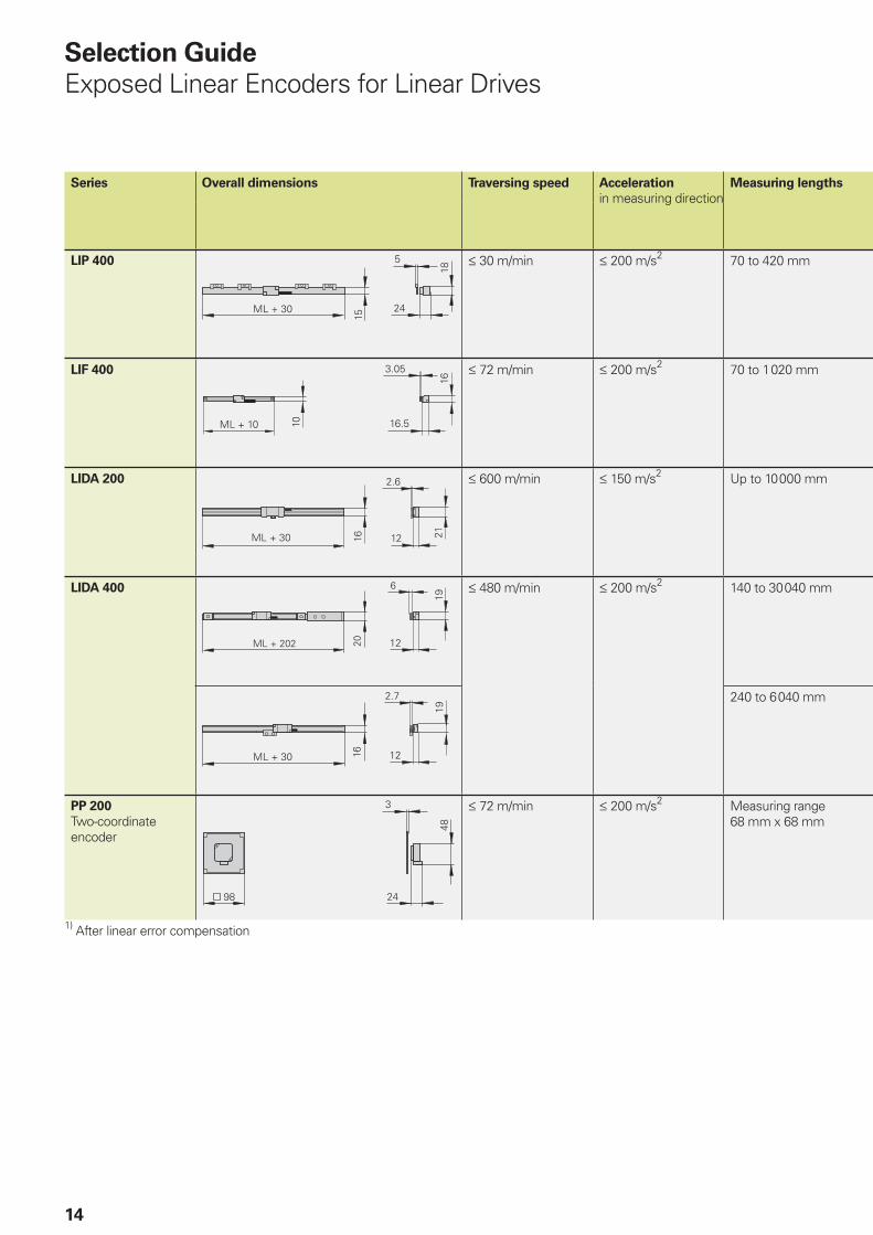
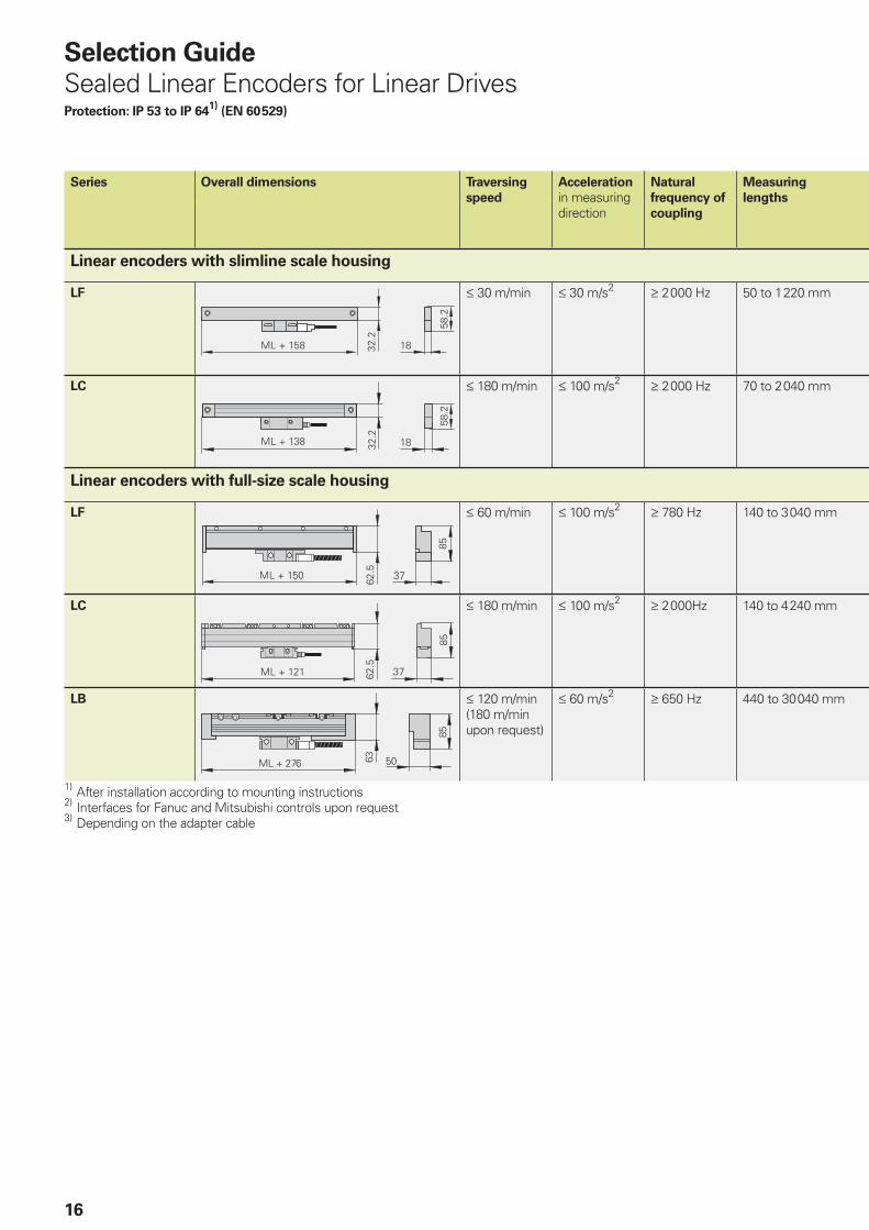
Series Overall dimensions Traversing speed Acceleration
in measuring directionMeasuring lengths
LIP 400 † 30 m/min † 200 m/s2 70 to 420 mm
LIF 400 † 72 m/min † 200 m/s2 70 to 1 020 mm
LIDA 200 † 600 m/min † 150 m/s2 Up to 10 000 mm
LIDA 400 † 480 m/min † 200 m/s2 140 to 30 040 mm
240 to 6 040 mm
PP 200
Two-coordinate encoder
† 72 m/min † 200 m/s2 Measuring range 68 mm x 68 mm
1) After linear error compensation
Selection Guide
Exposed Linear Encoders for Linear Drives
��� ��� ��
��
��
15
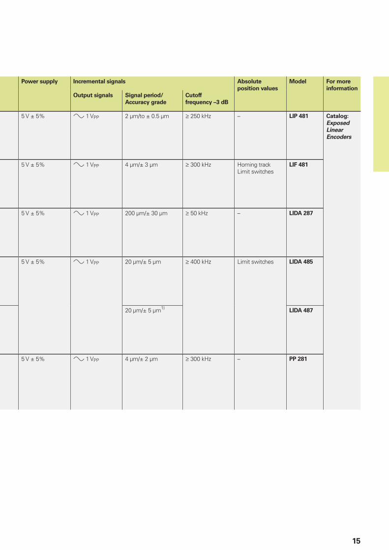
Power supply Incremental signals Absolute
position values
Model For more
information
Output signals Signal period/
Accuracy grade
Cutoff
frequency –3 dB
5 V ± 5% » 1 VPP 2 µm/to ± 0.5 µm ‡ 250 kHz – LIP 481 Catalog:
Exposed
Linear
Encoders
5 V ± 5% » 1 VPP 4 µm/± 3 µm ‡ 300 kHz Homing trackLimit switches
LIF 481
5 V ± 5% » 1 VPP 200 µm/± 30 µm ‡ 50 kHz – LIDA 287
5 V ± 5% » 1 VPP 20 µm/± 5 µm ‡ 400 kHz Limit switches LIDA 485
20 µm/± 5 µm1)LIDA 487
5 V ± 5% » 1 VPP 4 µm/± 2 µm ‡ 300 kHz – PP 281
16
Series Overall dimensions Traversing
speed
Acceleration
in measuring direction
Natural
frequency of
coupling
Measuring
lengths
Linear encoders with slimline scale housing
LF † 30 m/min † 30 m/s2 ‡ 2 000 Hz 50 to 1 220 mm
LC † 180 m/min † 100 m/s2 ‡ 2 000 Hz 70 to 2 040 mm
Linear encoders with full-size scale housing
LF † 60 m/min † 100 m/s2 ‡ 780 Hz 140 to 3 040 mm
LC † 180 m/min † 100 m/s2 ‡ 2 000Hz 140 to 4 240 mm
LB † 120 m/min(180 m/min upon request)
† 60 m/s2 ‡ 650 Hz 440 to 30 040 mm
1) After installation according to mounting instructions2) Interfaces for Fanuc and Mitsubishi controls upon request3) Depending on the adapter cable
Selection Guide
Sealed Linear Encoders for Linear DrivesProtection: IP 53 to IP 64
1) (EN 60 529)
��� ���� ����
���
����
���� ���� �
�
17
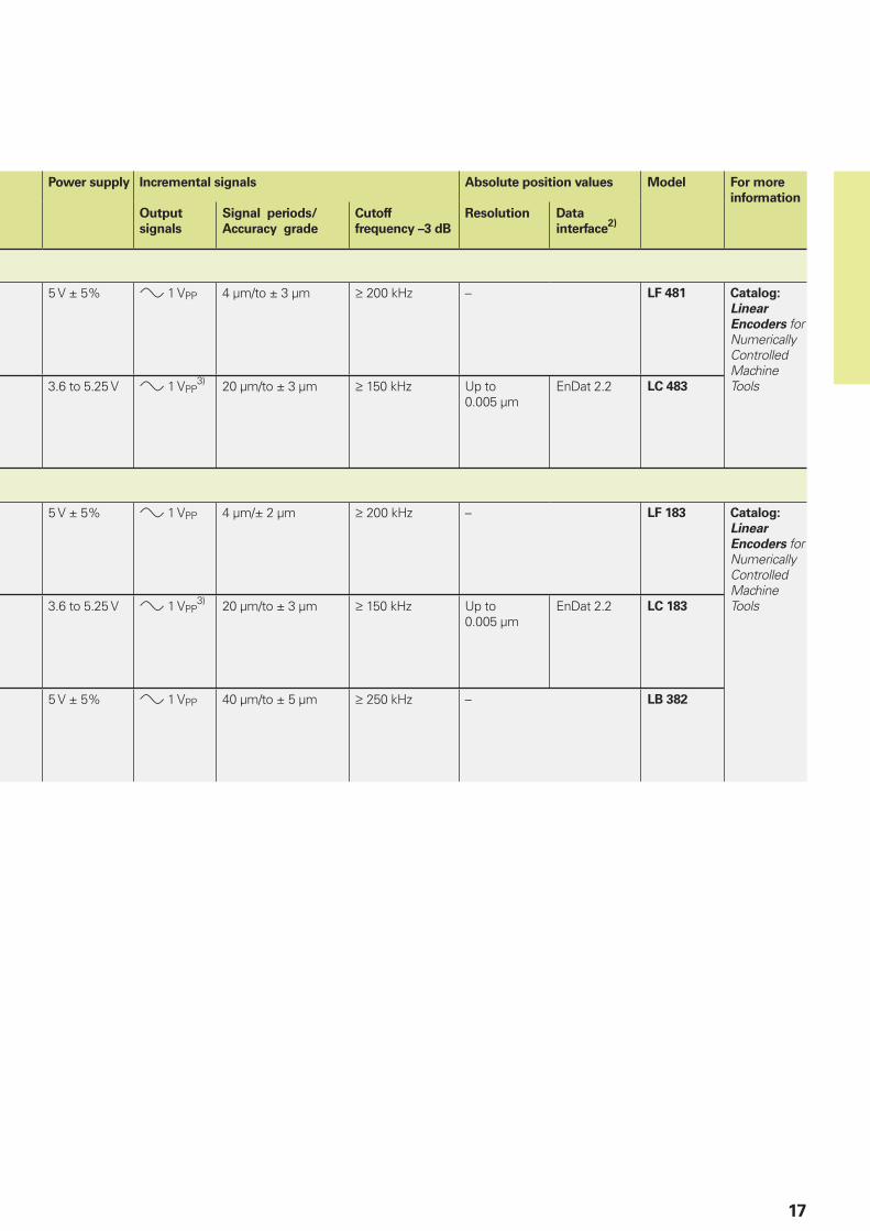
Power supply Incremental signals Absolute position values Model For more
information
Output
signals
Signal periods/
Accuracy grade
Cutoff
frequency –3 dB
Resolution Data
interface2)
5 V ± 5% » 1 VPP 4 µm/to ± 3 µm ‡ 200 kHz – LF 481 Catalog:
Linear
Encoders for Numerically Controlled Machine Tools3.6 to 5.25 V » 1 VPP
3) 20 µm/to ± 3 µm ‡ 150 kHz Up to 0.005 µm
EnDat 2.2 LC 483
5 V ± 5% » 1 VPP 4 µm/± 2 µm ‡ 200 kHz – LF 183 Catalog:
Linear
Encoders for Numerically Controlled Machine Tools3.6 to 5.25 V » 1 VPP
3) 20 µm/to ± 3 µm ‡ 150 kHz Up to 0.005 µm
EnDat 2.2 LC 183
5 V ± 5% » 1 VPP 40 µm/to ± 5 µm ‡ 250 kHz – LB 382
�� � �� ��� �������� ����� ������
����������
���������
����������
���������
��������
���������
�������
������
�������
������
������
�����
�
����
������
�����
����
��
��
18
Rotary Encoders and Angle Encoders for Three-Phase AC and
DC Motors
General Information
Speed stability
To ensure smooth drive performance, an encoder must provide a large number of
measuring steps per revolution. The encoders in the HEIDENHAIN product program are therefore designed to supply the necessary numbers of signal periods per revolution to meet the speed stability requirement.
HEIDENHAIN rotary and angle encoders featuring integral bearings and stator couplings provide very good performance: shaft misalignment within certain tolerances (see Specifi cations) do not cause any position error or impair speed stability.
At low speeds, the position error of the
encoder within one signal period affects speed stability. In encoders with purely serial data transmission, the LSB (Least Signifi cant Bit) goes into the speed stability. (See also Measuring Accuracy.)
Transmission of measuring signals
To ensure the best possible dynamic performance with digitally controlled motors, the sampling time of the speed controller should not exceed approx. 256 µs. The feedback values for the position and speed controller must therefore be available in the controlling system with the least possible delay.
High clock frequencies are needed to fulfi ll such demanding time requirements on position value transfer from the encoder to the controlling system with a serial data transmission (see also Interfaces; Absolute Position Values). HEIDENHAIN encoders for electric drives therefore provide the position values via the fast, purely serial EnDat 2.2 interface, or transmit additional incremental signals, which are available without delay for use in the subsequent electronics for speed and position control.
For standard drives, manufacturers primarily use HEIDENHAIN absolute encoders without integral bearing (ECI/EQI) or rotary encoders with TTL or HTL
compatible output signals—as well as additional commutation signals for permanent-magnet dc drives.
For digital speed control on machines with high requirements for dynamics, a large number of measuring steps is required—usually above 500 000 per revolution.For applications with standard drives, as with resolvers, approx. 60 000 measuring steps per revolution are suffi cient.
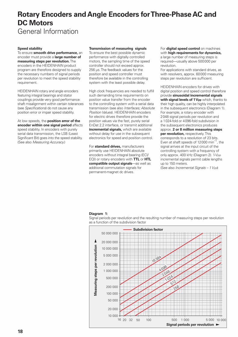
HEIDENHAIN encoders for drives with digital position and speed control therefore provide sinusoidal incremental signals
with signal levels of 1 VPP which, thanks to their high quality, can be highly interpolated in the subsequent electronics (Diagram 1). For example, a rotary encoder with 2 048 signal periods per revolution and a 1 024-fold or 4 096-fold subdivision in the subsequent electronics produces approx. 2 or 8 million measuring steps
per revolution, respectively. This corresponds to a resolution of 23 bits. Even at shaft speeds of 12 000 min–1, the signal arrives at the input circuit of the controlling system with a frequency of only approx. 400 kHz (Diagram 2). 1-VPP incremental signals permit cable lengths up to 150 meters.(See also Incremental Signals – 1 VPP)
Diagram 1:
Signal periods per revolution and the resulting number of measuring steps per revolution as a function of the subdivision factor
Subdivision factor
Signal periods per revolution
Measu
rin
g s
tep
s p
er
revo
luti
on
�����
����
����
��
����
19
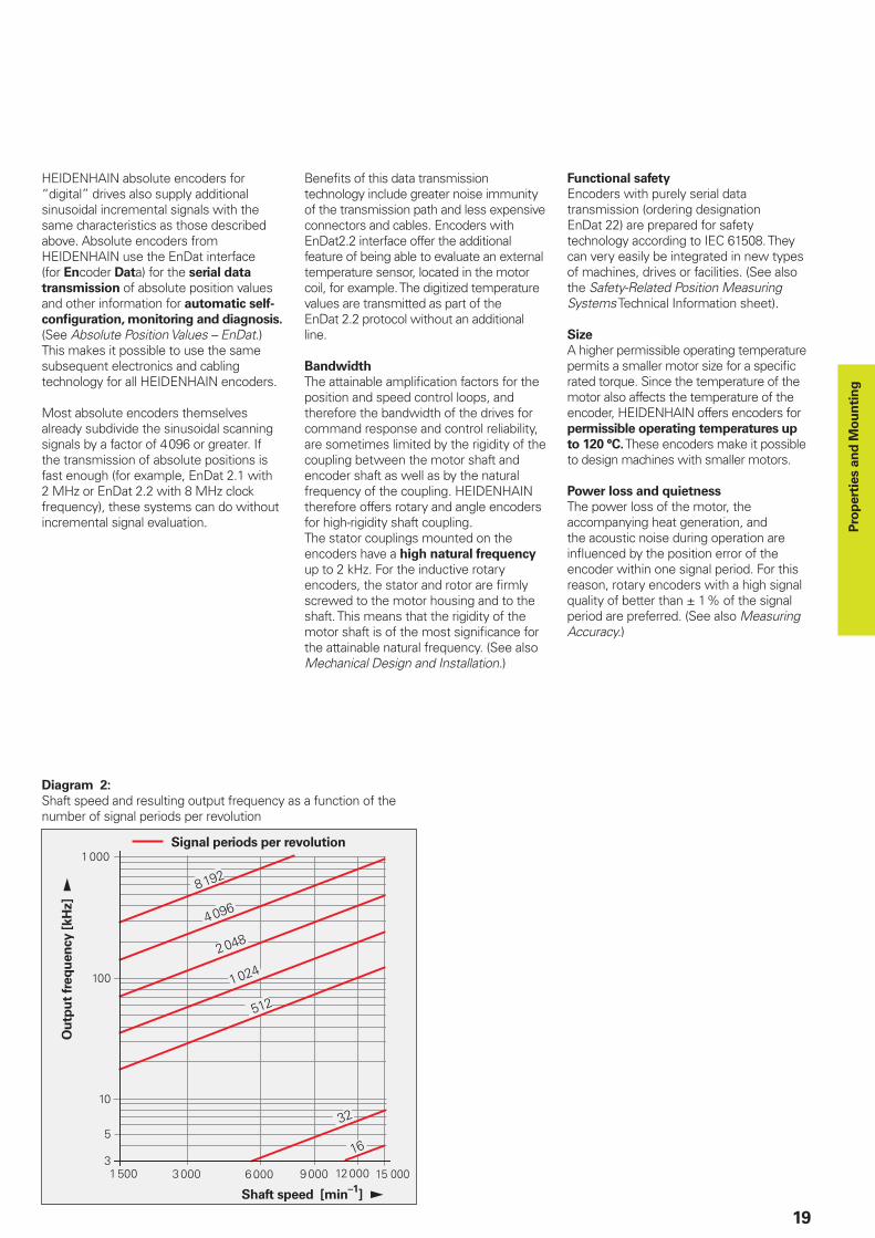
Diagram 2:
Shaft speed and resulting output frequency as a function of the number of signal periods per revolution
Shaft speed [min–1
]
Signal periods per revolution
Ou
tpu
t fr
eq
uen
cy [
kH
z]
HEIDENHAIN absolute encoders for “digital” drives also supply additional sinusoidal incremental signals with the same characteristics as those described above. Absolute encoders from HEIDENHAIN use the EnDat interface (for Encoder Data) for the serial data
transmission of absolute position values and other information for automatic self-
confi guration, monitoring and diagnosis. (See Absolute Position Values – EnDat.) This makes it possible to use the same subsequent electronics and cabling technology for all HEIDENHAIN encoders.
Most absolute encoders themselves already subdivide the sinusoidal scanning signals by a factor of 4 096 or greater. If the transmission of absolute positions is fast enough (for example, EnDat 2.1 with 2 MHz or EnDat 2.2 with 8 MHz clock frequency), these systems can do without incremental signal evaluation.
Benefi ts of this data transmission technology include greater noise immunity of the transmission path and less expensive connectors and cables. Encoders with EnDat2.2 interface offer the additional feature of being able to evaluate an external temperature sensor, located in the motor coil, for example. The digitized temperature values are transmitted as part of the EnDat 2.2 protocol without an additional line.
Bandwidth
The attainable amplifi cation factors for the position and speed control loops, and therefore the bandwidth of the drives for command response and control reliability, are sometimes limited by the rigidity of the coupling between the motor shaft and encoder shaft as well as by the natural frequency of the coupling. HEIDENHAIN therefore offers rotary and angle encoders for high-rigidity shaft coupling. The stator couplings mounted on the encoders have a high natural frequency up to 2 kHz. For the inductive rotary encoders, the stator and rotor are fi rmly screwed to the motor housing and to the shaft. This means that the rigidity of the motor shaft is of the most signifi cance for the attainable natural frequency. (See also Mechanical Design and Installation.)
Functional safety
Encoders with purely serial data transmission (ordering designation EnDat 22) are prepared for safety technology according to IEC 61508. They can very easily be integrated in new types of machines, drives or facilities. (See also the Safety-Related Position Measuring Systems Technical Information sheet).
Size
A higher permissible operating temperature permits a smaller motor size for a specifi c rated torque. Since the temperature of the motor also affects the temperature of the encoder, HEIDENHAIN offers encoders for permissible operating temperatures up
to 120 °C. These encoders make it possible to design machines with smaller motors.
Power loss and quietness
The power loss of the motor, the accompanying heat generation, and the acoustic noise during operation are infl uenced by the position error of the encoder within one signal period. For this reason, rotary encoders with a high signal quality of better than ± 1 % of the signal period are preferred. (See also Measuring Accuracy.)
Pro
pert
ies a
nd
Mo
un
tin
g
�����
����
����
20
Linear Encoders for Linear Drives
General Information
Selection criteria for linear encoders
HEIDENHAIN recommends the use of exposed linear encoders whenever the severity of contamination inherent in a particular machine environment does not preclude the use of optical measuring systems, and if relatively high accuracy is desired, e.g. for high-precision machine tools and measuring equipment, or for production, testing and inspecting equipment in the semiconductor industry.
Particularly for applications on machine tools that release coolants and lubricants, HEIDENHAIN recommends sealed linear
encoders. Here the requirements on the mounting surface and on machine guideway accuracy are less stringent than for exposed linear encoders, and therefore installation is faster.
Speed stability
To ensure smooth-running servo performance, the linear encoder must permit a resolution commensurate with the given speed control range:
On handling equipment, resolutions in the range of several microns are suffi cient.Feed drives for machine tools need resolutions of 0.1 µm and fi ner.Production equipment in the semiconductor industry requires resolutions of a few nanometers.
At low traversing speeds, the position
error within one signal period has a decisive infl uence on the speed stability of linear motors. (See also Measuring Accuracy.)
•
•
•
Traversing speeds
Exposed linear encoders function without contact between the scanning head and the scale. The maximum permissible traversing speed is limited only by the cutoff frequency (–3 dB) of the output signals.
On sealed linear encoders, the scanning unit is guided along the scale on a ball bearing. Sealing lips protect the scale and scanning unit from contamination. The ball bearing and sealing lips permit mechanical traversing speeds up to 180 m/min.
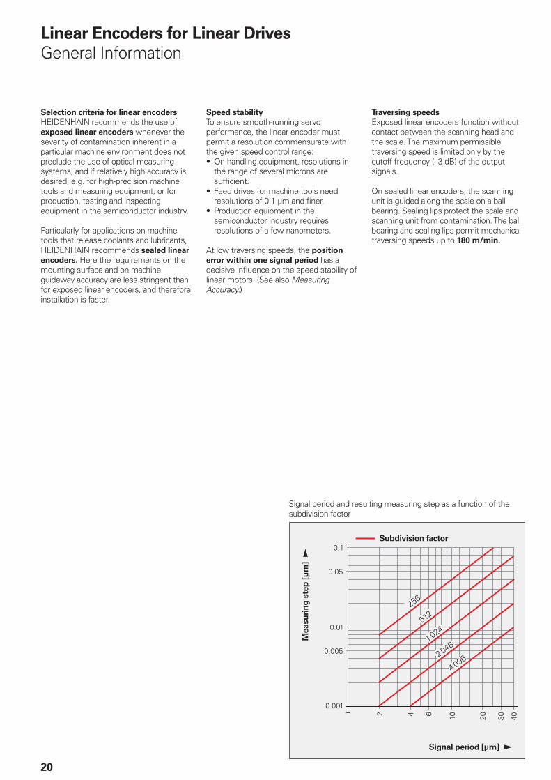
Signal period and resulting measuring step as a function of the subdivision factor
Subdivision factor
Signal period [µm]
Measu
rin
g s
tep
[µ
m]
���
����
�����
����
�����
21
Transmission of measuring signals
The information above on rotary and angle encoder signal transmission essentially applies also to linear encoders. If, for example, one wishes to traverse at a minimum velocity of 0.01 m/min with a sampling time of 250 µs, and if one assumes that the measuring step should change by at least one measuring step per sampling cycle, then one needs a measuring step of approx. 0.04 µm. To avoid the need for special measures in the subsequent electronics, input frequencies should be limited to less than 1 MHz. Linear encoders with sinusoidal output
signals are therefore best suited for high traversing speeds and small measuring steps. Sinusoidal voltage signals with levels of 1 VPP attain a –3 dB cutoff frequency of approx. 200 kHz and more at a permissible cable length of up to 150 m.
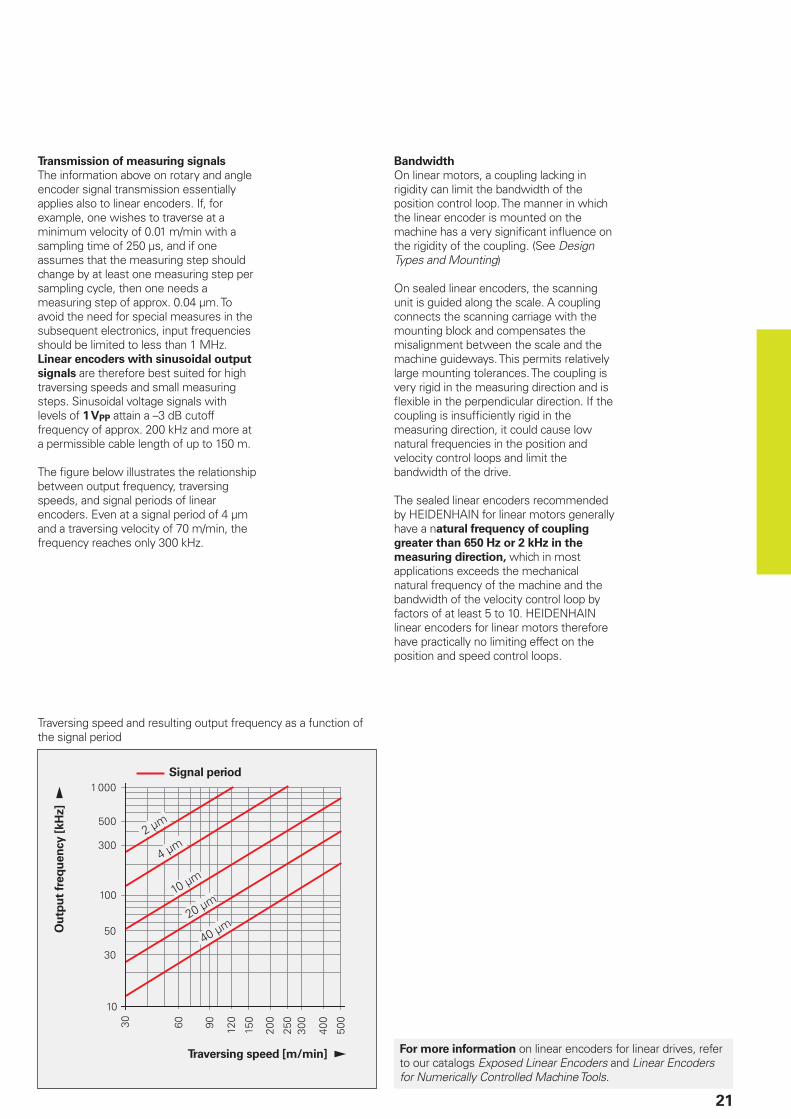
The fi gure below illustrates the relationship between output frequency, traversing speeds, and signal periods of linear encoders. Even at a signal period of 4 µm and a traversing velocity of 70 m/min, the frequency reaches only 300 kHz.
Bandwidth
On linear motors, a coupling lacking in rigidity can limit the bandwidth of the position control loop. The manner in which the linear encoder is mounted on the machine has a very signifi cant infl uence on the rigidity of the coupling. (See Design Types and Mounting)
On sealed linear encoders, the scanning unit is guided along the scale. A coupling connects the scanning carriage with the mounting block and compensates the misalignment between the scale and the machine guideways. This permits relatively large mounting tolerances. The coupling is very rigid in the measuring direction and is fl exible in the perpendicular direction. If the coupling is insuffi ciently rigid in the measuring direction, it could cause low natural frequencies in the position and velocity control loops and limit the bandwidth of the drive.
The sealed linear encoders recommended by HEIDENHAIN for linear motors generally have a natural frequency of coupling
greater than 650 Hz or 2 kHz in the
measuring direction, which in most applications exceeds the mechanical natural frequency of the machine and the bandwidth of the velocity control loop by factors of at least 5 to 10. HEIDENHAIN linear encoders for linear motors therefore have practically no limiting effect on the position and speed control loops.
Traversing speed and resulting output frequency as a function of the signal period
Signal period
Traversing speed [m/min]
Ou
tpu
t fr
eq
uen
cy [
kH
z]
For more information on linear encoders for linear drives, refer to our catalogs Exposed Linear Encoders and Linear Encoders for Numerically Controlled Machine Tools.
22
Measuring Principles
Measuring Standard
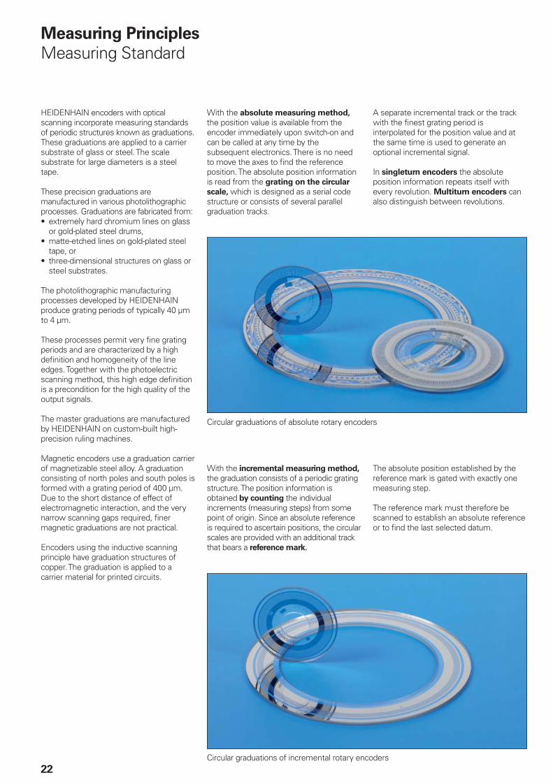
HEIDENHAIN encoders with optical scanning incorporate measuring standards of periodic structures known as graduations. These graduations are applied to a carrier substrate of glass or steel. The scale substrate for large diameters is a steel tape.
These precision graduations are manufactured in various photolithographic processes. Graduations are fabricated from:
extremely hard chromium lines on glass or gold-plated steel drums,matte-etched lines on gold-plated steel tape, orthree-dimensional structures on glass or steel substrates.
The photolithographic manufacturing processes developed by HEIDENHAIN produce grating periods of typically 40 µm to 4 µm.
These processes permit very fi ne grating periods and are characterized by a high defi nition and homogeneity of the line edges. Together with the photoelectric scanning method, this high edge defi nition is a precondition for the high quality of the output signals.
The master graduations are manufactured by HEIDENHAIN on custom-built high-precision ruling machines.
Magnetic encoders use a graduation carrier of magnetizable steel alloy. A graduation consisting of north poles and south poles is formed with a grating period of 400 µm. Due to the short distance of effect of electromagnetic interaction, and the very narrow scanning gaps required, fi ner magnetic graduations are not practical.
Encoders using the inductive scanning principle have graduation structures of copper. The graduation is applied to a carrier material for printed circuits.
•
•
•
With the absolute measuring method, the position value is available from the encoder immediately upon switch-on and can be called at any time by the subsequent electronics. There is no need to move the axes to fi nd the reference position. The absolute position information is read from the grating on the circular
scale, which is designed as a serial code structure or consists of several parallel graduation tracks.
A separate incremental track or the track with the fi nest grating period is interpolated for the position value and at the same time is used to generate an optional incremental signal.
In singleturn encoders the absolute position information repeats itself with every revolution. Multiturn encoders can also distinguish between revolutions.
Circular graduations of absolute rotary encoders
With the incremental measuring method, the graduation consists of a periodic grating structure. The position information is obtained by counting the individual increments (measuring steps) from some point of origin. Since an absolute reference is required to ascertain positions, the circular scales are provided with an additional track that bears a reference mark.
The absolute position established by the reference mark is gated with exactly one measuring step.
The reference mark must therefore be scanned to establish an absolute reference or to fi nd the last selected datum.
Circular graduations of incremental rotary encoders
23
Scanning Methods
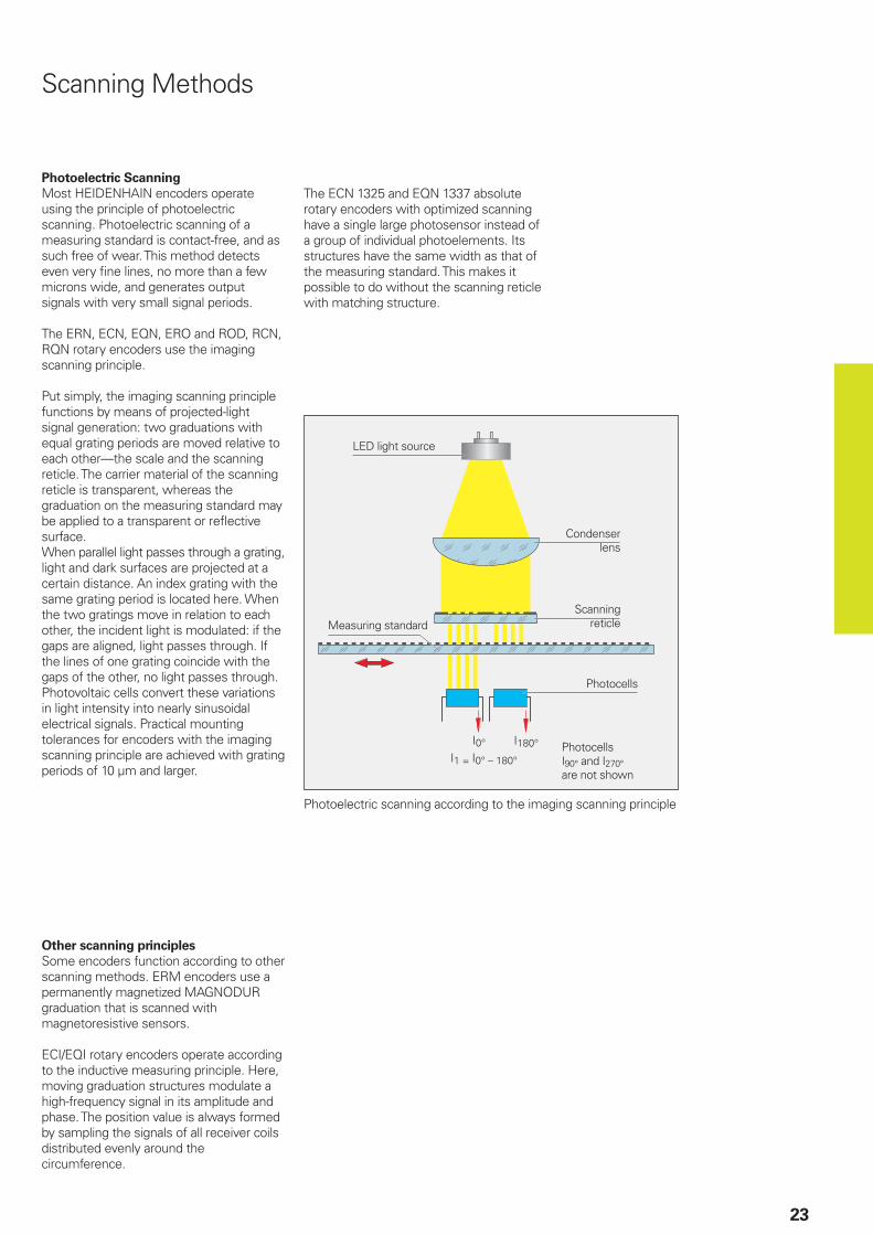
Photoelectric Scanning
Most HEIDENHAIN encoders operate using the principle of photoelectric scanning. Photoelectric scanning of a measuring standard is contact-free, and as such free of wear. This method detects even very fi ne lines, no more than a few microns wide, and generates output signals with very small signal periods.
The ERN, ECN, EQN, ERO and ROD, RCN, RQN rotary encoders use the imaging scanning principle.
Put simply, the imaging scanning principle functions by means of projected-light signal generation: two graduations with equal grating periods are moved relative to each other—the scale and the scanning reticle. The carrier material of the scanning reticle is transparent, whereas the graduation on the measuring standard may be applied to a transparent or refl ective surface.When parallel light passes through a grating, light and dark surfaces are projected at a certain distance. An index grating with the same grating period is located here. When the two gratings move in relation to each other, the incident light is modulated: if the gaps are aligned, light passes through. If the lines of one grating coincide with the gaps of the other, no light passes through. Photovoltaic cells convert these variations in light intensity into nearly sinusoidal electrical signals. Practical mounting tolerances for encoders with the imaging scanning principle are achieved with grating periods of 10 µm and larger.
Other scanning principles
Some encoders function according to other scanning methods. ERM encoders use a permanently magnetized MAGNODUR graduation that is scanned with magnetoresistive sensors.
ECI/EQI rotary encoders operate according to the inductive measuring principle. Here, moving graduation structures modulate a high-frequency signal in its amplitude and phase. The position value is always formed by sampling the signals of all receiver coils distributed evenly around the circumference.
Photoelectric scanning according to the imaging scanning principle
LED light source
Condenser lens
Scanning reticle
Photocells
Measuring standard
Photocells I90° and I270° are not shown
The ECN 1325 and EQN 1337 absolute rotary encoders with optimized scanning have a single large photosensor instead of a group of individual photoelements. Its structures have the same width as that of the measuring standard. This makes it possible to do without the scanning reticle with matching structure.
24
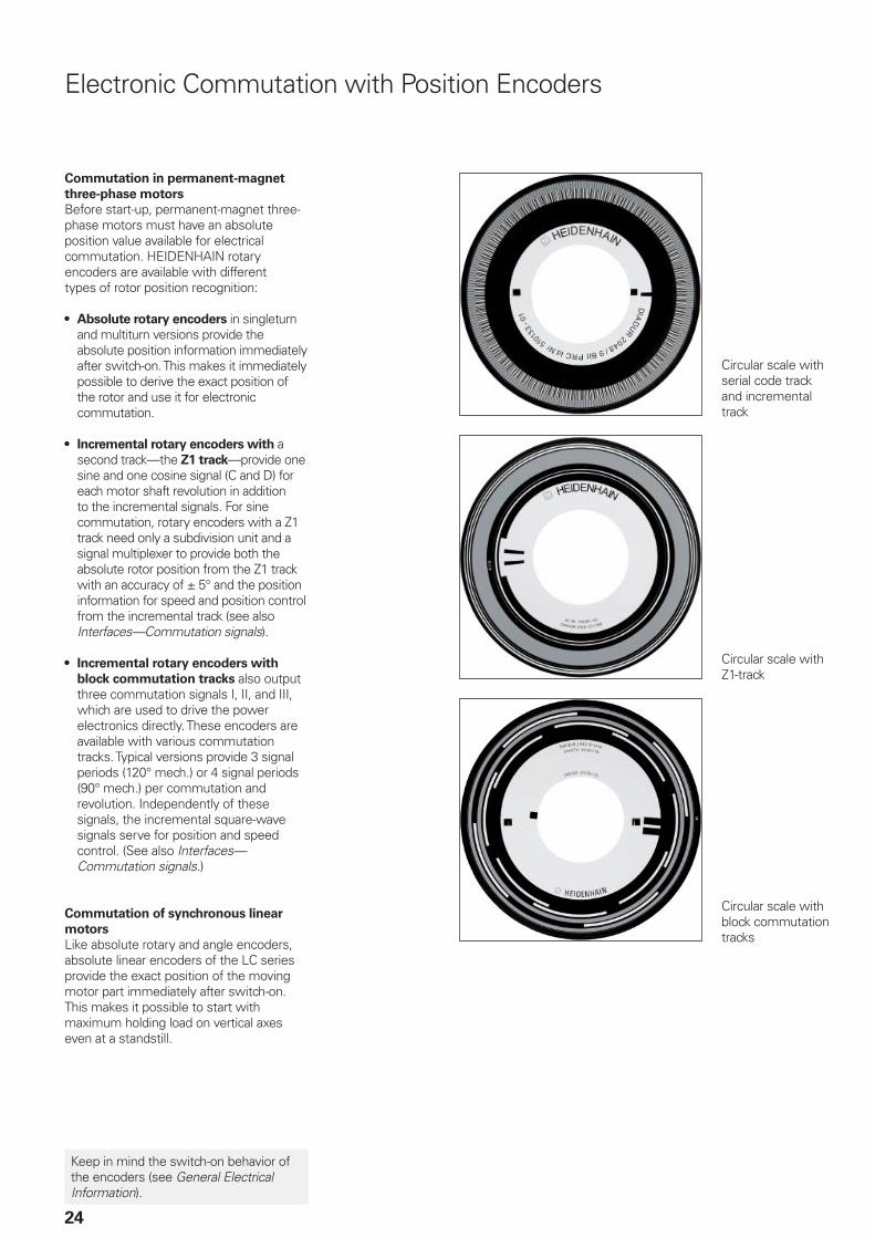
Electronic Commutation with Position Encoders
Commutation in permanent-magnet
three-phase motors
Before start-up, permanent-magnet three-phase motors must have an absolute position value available for electrical commutation. HEIDENHAIN rotary encoders are available with different types of rotor position recognition:
Absolute rotary encoders in singleturn and multiturn versions provide the absolute position information immediately after switch-on. This makes it immediately possible to derive the exact position of the rotor and use it for electronic commutation.
Incremental rotary encoders with a second track—the Z1 track—provide one sine and one cosine signal (C and D) for each motor shaft revolution in addition to the incremental signals. For sine commutation, rotary encoders with a Z1 track need only a subdivision unit and a signal multiplexer to provide both the absolute rotor position from the Z1 track with an accuracy of ± 5° and the position information for speed and position control from the incremental track (see also Interfaces—Commutation signals).
Incremental rotary encoders with
block commutation tracks also output three commutation signals I, II, and III, which are used to drive the power electronics directly. These encoders are available with various commutation tracks. Typical versions provide 3 signal periods (120° mech.) or 4 signal periods (90° mech.) per commutation and revolution. Independently of these signals, the incremental square-wave signals serve for position and speed control. (See also Interfaces—Commutation signals.)
Commutation of synchronous linear
motors
Like absolute rotary and angle encoders, absolute linear encoders of the LC series provide the exact position of the moving motor part immediately after switch-on. This makes it possible to start with maximum holding load on vertical axes even at a standstill.
•
•
•
Circular scale with serial code track and incremental track
Circular scale with Z1-track
Circular scale with block commutation tracks
Keep in mind the switch-on behavior of the encoders (see General Electrical Information).
25
The quantities infl uencing the accuracy of linear encoders are listed in the Linear Encoders for Numerically Controlled Machine Tools and Exposed Linear Encoders catalogs.
The accuracy of angular measurement is mainly determined by:1. Quality of the graduation2. Quality of scanning3. Quality of the signal processing
electronics4. Eccentricity of the graduation to the
bearing5. Error due to radial deviation of the
bearing6. Elasticity of the encoder shaft and
coupling with the drive shaft7. Elasticity of the stator coupling (ERN,
ECN, EQN) or shaft coupling (ROD, ROC, ROQ)
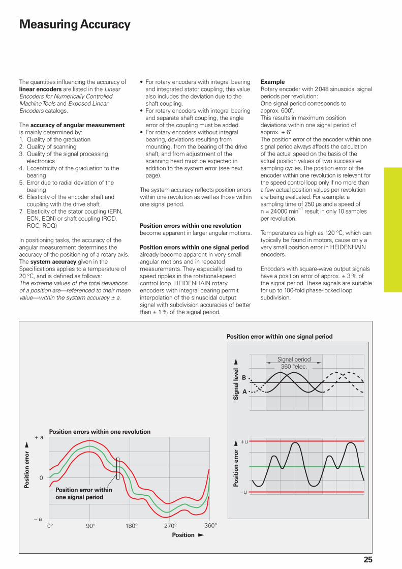
In positioning tasks, the accuracy of the angular measurement determines the accuracy of the positioning of a rotary axis. The system accuracy given in the Specifi cations applies to a temperature of 20 °C, and is defi ned as follows:The extreme values of the total deviations of a position are—referenced to their mean value—within the system accuracy ± a.
For rotary encoders with integral bearing and integrated stator coupling, this value also includes the deviation due to the shaft coupling.For rotary encoders with integral bearing and separate shaft coupling, the angle error of the coupling must be added.For rotary encoders without integral bearing, deviations resulting from mounting, from the bearing of the drive shaft, and from adjustment of the scanning head must be expected in addition to the system error (see next page).
The system accuracy refl ects position errors within one revolution as well as those within one signal period.
Position errors within one revolution become apparent in larger angular motions. Position errors within one signal period already become apparent in very small angular motions and in repeated measurements. They especially lead to speed ripples in the rotational-speed control loop. HEIDENHAIN rotary encoders with integral bearing permit interpolation of the sinusoidal output signal with subdivision accuracies of better than ± 1 % of the signal period.
•
•
•
Example
Rotary encoder with 2 048 sinusoidal signal periods per revolution:One signal period corresponds to approx. 600".This results in maximum position deviations within one signal period of approx. ± 6".The position error of the encoder within one signal period always affects the calculation of the actual speed on the basis of the actual position values of two successive sampling cycles. The position error of the encoder within one revolution is relevant for the speed control loop only if no more than a few actual position values per revolution are being evaluated. For example: a sampling time of 250 µs and a speed of n 24 000 min–1 result in only 10 samples per revolution.
Temperatures as high as 120 °C, which can typically be found in motors, cause only a very small position error in HEIDENHAIN encoders.
Encoders with square-wave output signals have a position error of approx. ± 3 % of the signal period. These signals are suitable for up to 100-fold phase-locked loop subdivision.
Position error within one signal period
Position errors within one revolution
Measuring Accuracy
Position error within
one signal period
Po
sit
ion
err
or
Po
sit
ion
err
or
Sig
nal le
vel
Signal period360 °elec.
Position
� � �� � �� ���
��
�
��
���
���
��
���
��
�������������������
������������������
�������������������
26
Measuring Accuracy
Rotary Encoders without Integral Bearing
Rotary Encoders with
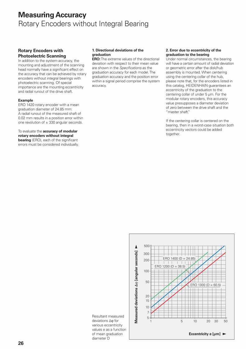
Photoelectric ScanningIn addition to the system accuracy, the mounting and adjustment of the scanning head normally have a signifi cant effect on the accuracy that can be achieved by rotary encoders without integral bearings with photoelectric scanning. Of special importance are the mounting eccentricity and radial runout of the drive shaft.
Example
ERO 1420 rotary encoder with a mean graduation diameter of 24.85 mm:A radial runout of the measured shaft of 0.02 mm results in a position error within one revolution of ± 330 angular seconds.
To evaluate the accuracy of modular
rotary encoders without integral
bearing (ERO), each of the signifi cant errors must be considered individually.
1. Directional deviations of the
graduation
ERO: The extreme values of the directional deviation with respect to their mean value are shown in the Specifi cations as the graduation accuracy for each model. The graduation accuracy and the position error within a signal period comprise the system accuracy.
2. Error due to eccentricity of the
graduation to the bearing
Under normal circumstances, the bearing will have a certain amount of radial deviation or geometric error after the disk/hub assembly is mounted. When centering using the centering collar of the hub, please note that, for the encoders listed in this catalog, HEIDENHAIN guarantees an eccentricity of the graduation to the centering collar of under 5 µm. For the modular rotary encoders, this accuracy value presupposes a diameter deviation of zero between the drive shaft and the “master shaft.”
If the centering collar is centered on the bearing, then in a worst-case situation both eccentricity vectors could be added together.
Resultant measured deviations ¹ϕ for various eccentricity values e as a function of mean graduation diameter D
Eccentricity e [µm]
Measu
red
devia
tio
ns ¹
ϕ [a
ng
ula
r seco
nd
s]
�
�
�
��
�
��
27
The following relationship exists between the eccentricity e, the mean graduation diameter D and the measuring error ¹ϕ (see illustration below):
¹ϕ = ± 412 ·
¹ϕ = Measuring error in " (angular seconds)
e = Eccentricity of the radial grating to the bearing in µm
D = Mean graduation diameter in mm
Model Mean graduation diameter D
Error per 1 µm of eccentricity
ERO 1420
ERO 1470
ERO 1480
D = 24.85 mm ± 16.5"
ERO 1225
ERO 1285
D = 38.5 mm ± 10.7"
ERO 1324
ERO 1384
D = 60.5 mm ± 6.8"
eD
3. Error due to radial deviation of the
bearing
The equation for the measuring error ¹ϕ is also valid for radial deviation of the bearing if the value e is replaced with the eccentricity value, i.e. half of the radial deviation (half of the displayed value).Bearing compliance to radial shaft loading causes similar errors.
4. Position error within one signal
period ¹ϕu
The scanning units of all HEIDENHAIN encoders are adjusted so that without any further electrical adjustment being necessary while mounting, the maximum position error values within one signal period will not exceed the values listed below.
Model Line count Position error within one signal period ¹ϕu
TTL 1 VPP
ERO 5 0002 0481 5001 0241 000 512
† ± 8.0"† ± 19.0"† ± 26.0"† ± 38.0"† ± 40.0"† ± 76.0"
† ± 2.7"† ± 6.5"† ± 8.7"† ± 13.0"† ± 14.0"† ± 25.0"
The values for the position errors within one signal period are already included in the system accuracy. Larger errors can occur if the mounting tolerances are exceeded.
Rotary Encoders with Inductive
ScanningFor rotary encoders without integrated bearing with inductive scanning, the attainable accuracy depends on the power supply, the temperature, the rotational speed, the working gap between the rotor and stator, and on the mounting conditions. The system accuracy stated in the Specifi cations takes all these factors of infl uence into account, as long as the permissible operating parameters and mounting tolerances are maintained.
Measuring error ¹ϕ as a function of the mean graduation diameter D and the eccentricity e
M Center of graduationϕ “True” angleϕ‘ Scanned angle
Scanning unit
28
Mechanical Design Types and Mounting
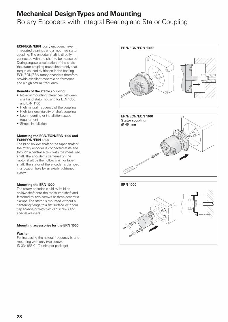
Rotary Encoders with Integral Bearing and Stator Coupling
ECN/EQN/ERN rotary encoders have integrated bearings and a mounted stator coupling. The encoder shaft is directly connected with the shaft to be measured. During angular acceleration of the shaft, the stator coupling must absorb only that torque caused by friction in the bearing. ECN/EQN/ERN rotary encoders therefore provide excellent dynamic performance and a high natural frequency.
Benefi ts of the stator coupling:
No axial mounting tolerances between shaft and stator housing for ExN 1300 and ExN 1100High natural frequency of the couplingHigh torsional rigidity of shaft couplingLow mounting or installation space requirementSimple installation
Mounting the ECN/EQN/ERN 1100 and
ECN/EQN/ERN 1300
The blind hollow shaft or the taper shaft of the rotary encoder is connected at its end through a central screw with the measured shaft. The encoder is centered on the motor shaft by the hollow shaft or taper shaft. The stator of the encoder is clamped in a location hole by an axially tightened screw.
Mounting the ERN 1000
The rotary encoder is slid by its blind hollow shaft onto the measured shaft and fastened by two screws or three eccentric clamps. The stator is mounted without a centering fl ange to a fl at surface with four cap screws or with two cap screws and special washers.
Mounting accessories for the ERN 1000
Washer
For increasing the natural frequency fN and mounting with only two screwsID 334 653-01 (2 units per package)
•
•••
•
ERN/ECN/EQN 1300
ERN/ECN/EQN 1100
Stator coupling
¬ 45 mm
ERN 1000
29
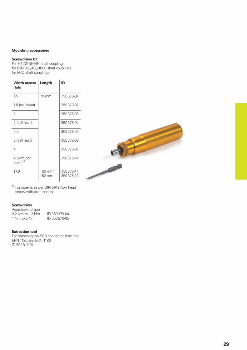
Mounting accessories
Screwdriver bit
For HEIDENHAIN shaft couplings,for ExN 100/400/1000 shaft couplingsfor ERO shaft couplings
Width across
fl ats
Length ID
1.5 70 mm 350 378-01
1.5 (ball head) 350 378-02
2 350 378-03
2 (ball head) 350 378-04
2.5 350 378-05
3 (ball head) 350 378-08
4 350 378-07
4 (with dog point)1)
350 378-14
TX8 89 mm152 mm
350 378-11350 378-12
1) For screws as per DIN 6912 (low head screw with pilot recess)
Screwdriver
Adjustable torque0.2 Nm to 1.2 Nm ID 350 379-041 Nm to 5 Nm ID 350 379-05
Extraction tool
For removing the PCB connector from the ERN 1120 and ERN 1180ID 592 818-01
30
Mechanical Design Types and Mounting
Rotary Encoders without Integral Bearing
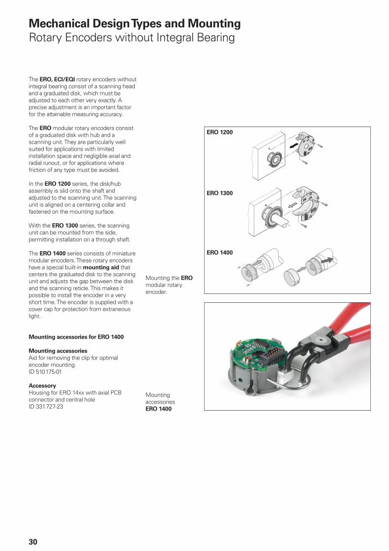
The ERO, ECI/EQI rotary encoders without integral bearing consist of a scanning head and a graduated disk, which must be adjusted to each other very exactly. A precise adjustment is an important factor for the attainable measuring accuracy.
The ERO modular rotary encoders consist of a graduated disk with hub and a scanning unit. They are particularly well suited for applications with limited installation space and negligible axial and radial runout, or for applications where friction of any type must be avoided.
In the ERO 1200 series, the disk/hub assembly is slid onto the shaft and adjusted to the scanning unit. The scanning unit is aligned on a centering collar and fastened on the mounting surface.
With the ERO 1300 series, the scanning unit can be mounted from the side, permitting installation on a through shaft.
The ERO 1400 series consists of miniature modular encoders. These rotary encoders have a special built-in mounting aid that centers the graduated disk to the scanning unit and adjusts the gap between the disk and the scanning reticle. This makes it possible to install the encoder in a very short time. The encoder is supplied with a cover cap for protection from extraneous light.
Mounting accessories for ERO 1400
Mounting accessories
Aid for removing the clip for optimal encoder mounting.ID 510 175-01
Accessory
Housing for ERO 14xx with axial PCB connector and central holeID 331 727-23
Mounting accessoriesERO 1400
Mounting the ERO modular rotary encoder.
ERO 1200
ERO 1300
ERO 1400
� ���� ��� ���� ���������������������
��
��
���
��
���
���
���
���� ���
31
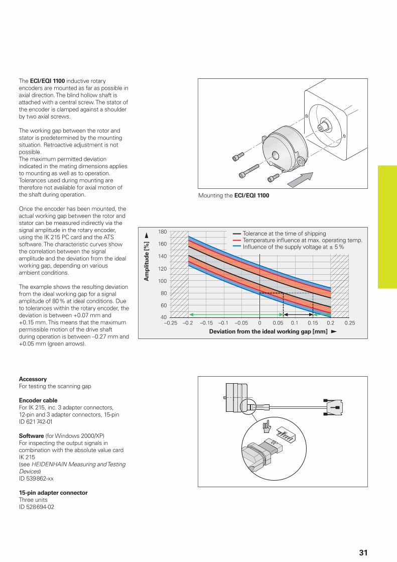
The ECI/EQI 1100 inductive rotary encoders are mounted as far as possible in axial direction. The blind hollow shaft is attached with a central screw. The stator of the encoder is clamped against a shoulder by two axial screws.
The working gap between the rotor and stator is predetermined by the mounting situation. Retroactive adjustment is not possible.The maximum permitted deviation indicated in the mating dimensions applies to mounting as well as to operation. Tolerances used during mounting are therefore not available for axial motion of the shaft during operation.
Once the encoder has been mounted, the actual working gap between the rotor and stator can be measured indirectly via the signal amplitude in the rotary encoder, using the IK 215 PC card and the ATS software. The characteristic curves show the correlation between the signal amplitude and the deviation from the ideal working gap, depending on various ambient conditions.
The example shows the resulting deviation from the ideal working gap for a signal amplitude of 80 % at ideal conditions. Due to tolerances within the rotary encoder, the deviation is between +0.07 mm and +0.15 mm. This means that the maximum permissible motion of the drive shaft during operation is between –0.27 mm and +0.05 mm (green arrows).
Mounting the ECI/EQI 1100
Accessory
For testing the scanning gap
Encoder cable
For IK 215, inc. 3 adapter connectors, 12-pin and 3 adapter connectors, 15-pinID 621 742-01
Software (for Windows 2000/XP) For inspecting the output signals in combination with the absolute value card IK 215(see HEIDENHAIN Measuring and Testing Devices)ID 539 862-xx
15-pin adapter connector
Three unitsID 528 694-02
Am
plitu
de [
%]
Deviation from the ideal working gap [mm]
Tolerance at the time of shippingTemperature infl uence at max. operating temp.Infl uence of the supply voltage at ± 5 %
32
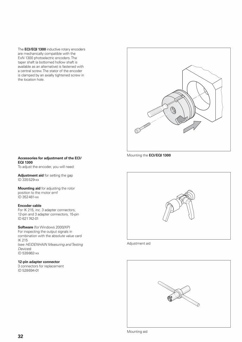
The ECI/EQI 1300 inductive rotary encoders are mechanically compatible with the ExN 1300 photoelectric encoders. The taper shaft (a bottomed hollow shaft is available as an alternative) is fastened with a central screw. The stator of the encoder is clamped by an axially tightened screw in the location hole.
Mounting the ECI/EQI 1300
Adjustment aid
Mounting aid
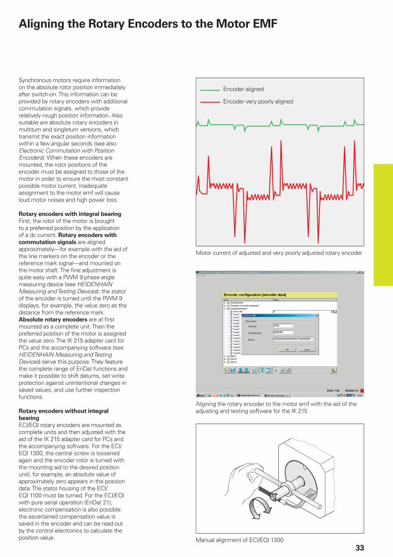
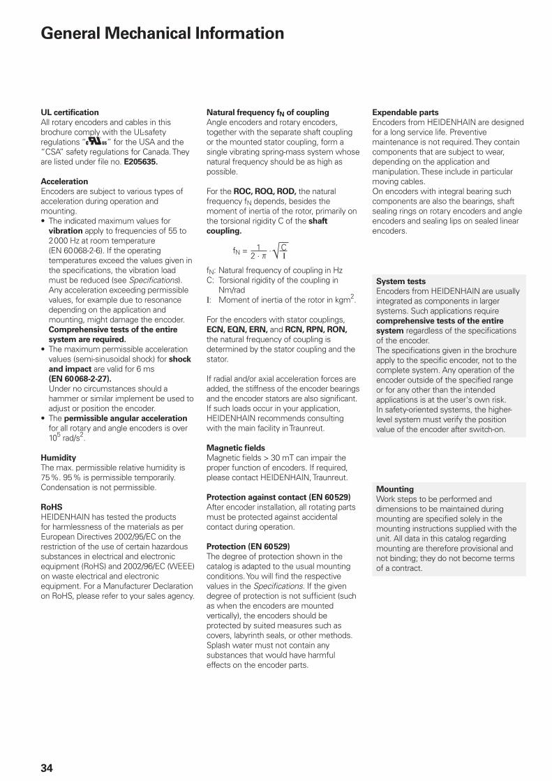
Accessories for adjustment of the ECI/
EQI 1300
To adjust the encoder, you will need:
Adjustment aid for setting the gapID 335 529-xx
Mounting aid for adjusting the rotor position to the motor emfID 352 481-xx
Encoder cable
For IK 215, inc. 3 adapter connectors, 12-pin and 3 adapter connectors, 15-pinID 621 742-01
Software (for Windows 2000/XP) For inspecting the output signals in combination with the absolute value card IK 215(see HEIDENHAIN Measuring and Testing Devices)ID 539 862-xx
12-pin adapter connector
3 connectors for replacementID 528 694-01
33
Aligning the Rotary Encoders to the Motor EMF
Synchronous motors require information on the absolute rotor position immediately after switch-on. This information can be provided by rotary encoders with additional commutation signals, which provide relatively rough position information. Also suitable are absolute rotary encoders in multiturn and singleturn versions, which transmit the exact position information within a few angular seconds (see also Electronic Commutation with Position Encoders). When these encoders are mounted, the rotor positions of the encoder must be assigned to those of the motor in order to ensure the most constant possible motor current. Inadequate assignment to the motor emf will cause loud motor noises and high power loss.
Rotary encoders with integral bearing
First, the rotor of the motor is brought to a preferred position by the application of a dc current. Rotary encoders with
commutation signals are aligned approximately—for example with the aid of the line markers on the encoder or the reference mark signal—and mounted on the motor shaft. The fi ne adjustment is quite easy with a PWM 9 phase angle measuring device (see HEIDENHAIN Measuring and Testing Devices): the stator of the encoder is turned until the PWM 9 displays, for example, the value zero as the distance from the reference mark. Absolute rotary encoders are at fi rst mounted as a complete unit. Then the preferred position of the motor is assigned the value zero. The IK 215 adapter card for PCs and the accompanying software (see HEIDENHAIN Measuring and Testing Devices) serve this purpose. They feature the complete range of EnDat functions and make it possible to shift datums, set write protection against unintentional changes in saved values, and use further inspection functions.
Rotary encoders without integral
bearing
ECI/EQI rotary encoders are mounted as complete units and then adjusted with the aid of the IK 215 adapter card for PCs and the accompanying software. For the ECI/EQI 1300, the central screw is loosened again and the encoder rotor is turned with the mounting aid to the desired position until, for example, an absolute value of approximately zero appears in the position data. The stator housing of the ECI/EQI 1100 must be turned. For the ECI/EQI with pure serial operation (EnDat 21), electronic compensation is also possible: the ascertained compensation value is saved in the encoder and can be read out by the control electronics to calculate the position value.
Motor current of adjusted and very poorly adjusted rotary encoder
Aligning the rotary encoder to the motor emf with the aid of the adjusting and testing software for the IK 215
Manual alignment of ECI/EQI 1300
Encoder aligned
Encoder very poorly aligned
34
General Mechanical Information
UL certifi cation
All rotary encoders and cables in this brochure comply with the UL-safety regulations “ ” for the USA and the “CSA” safety regulations for Canada. They are listed under fi le no. E205635.
Acceleration
Encoders are subject to various types of acceleration during operation and mounting.
The indicated maximum values for vibration apply to frequencies of 55 to 2 000 Hz at room temperature (EN 60 068-2-6). If the operating temperatures exceed the values given in the specifi cations, the vibration load must be reduced (see Specifi cations). Any acceleration exceeding permissible values, for example due to resonance depending on the application and mounting, might damage the encoder. Comprehensive tests of the entire
system are required.
The maximum permissible acceleration values (semi-sinusoidal shock) for shock
and impact are valid for 6 ms
(EN 60 068-2-27).
Under no circumstances should a hammer or similar implement be used to adjust or position the encoder.The permissible angular acceleration for all rotary and angle encoders is over 105 rad/s2.
Humidity
The max. permissible relative humidity is 75 %. 95 % is permissible temporarily. Condensation is not permissible.
RoHS
HEIDENHAIN has tested the products for harmlessness of the materials as per European Directives 2002/95/EC on the restriction of the use of certain hazardous substances in electrical and electronic equipment (RoHS) and 2002/96/EC (WEEE) on waste electrical and electronic equipment. For a Manufacturer Declaration on RoHS, please refer to your sales agency.
•
•
•
Natural frequency fN of coupling
Angle encoders and rotary encoders, together with the separate shaft coupling or the mounted stator coupling, form a single vibrating spring-mass system whose natural frequency should be as high as possible.
For the ROC, ROQ, ROD, the natural frequency fN depends, besides the moment of inertia of the rotor, primarily on the torsional rigidity C of the shaft
coupling.
fN = ·
fN: Natural frequency of coupling in HzC: Torsional rigidity of the coupling in
Nm/radΙ: Moment of inertia of the rotor in kgm2.
For the encoders with stator couplings, ECN, EQN, ERN, and RCN, RPN, RON, the natural frequency of coupling is determined by the stator coupling and the stator.
If radial and/or axial acceleration forces are added, the stiffness of the encoder bearings and the encoder stators are also signifi cant. If such loads occur in your application, HEIDENHAIN recommends consulting with the main facility in Traunreut.
Magnetic fi elds
Magnetic fi elds > 30 mT can impair the proper function of encoders. If required, please contact HEIDENHAIN, Traunreut.
Protection against contact (EN 60 529)
After encoder installation, all rotating parts must be protected against accidental contact during operation.
Protection (EN 60 529)
The degree of protection shown in the catalog is adapted to the usual mounting conditions. You will fi nd the respective values in the Specifi cations. If the given degree of protection is not suffi cient (such as when the encoders are mounted vertically), the encoders should be protected by suited measures such as covers, labyrinth seals, or other methods. Splash water must not contain any substances that would have harmful effects on the encoder parts.
12 · þ
C √ Ι
Expendable parts
Encoders from HEIDENHAIN are designed for a long service life. Preventive maintenance is not required. They contain components that are subject to wear, depending on the application and manipulation. These include in particular moving cables.On encoders with integral bearing such components are also the bearings, shaft sealing rings on rotary encoders and angle encoders and sealing lips on sealed linear encoders.
System tests
Encoders from HEIDENHAIN are usually integrated as components in larger systems. Such applications require comprehensive tests of the entire
system regardless of the specifi cations of the encoder.The specifi cations given in the brochure apply to the specifi c encoder, not to the complete system. Any operation of the encoder outside of the specifi ed range or for any other than the intended applications is at the user's own risk.In safety-oriented systems, the higher-level system must verify the position value of the encoder after switch-on.
Mounting
Work steps to be performed and dimensions to be maintained during mounting are specifi ed solely in the mounting instructions supplied with the unit. All data in this catalog regarding mounting are therefore provisional and not binding; they do not become terms of a contract.
��������
�������
35
Temperature ranges
For the unit in its packaging, the storage
temperature range is –30 °C to +80 °C.The operating temperature range indicates the temperatures the encoder may reach during operation in the actual installation environment. The function of the encoder is guaranteed within this range (DIN 32 878). The operating temperature is measured on the face of the encoder fl ange and must not be confused with the ambient temperature.
The temperature of the encoder is infl uenced by:
Mounting conditionsThe ambient temperatureSelf-heating of the encoder
The self-heating of an encoder depends both on its design characteristics (stator coupling/solid shaft, shaft sealing ring, etc.) and on the operating parameters (rotational speed, power supply). Higher heat generation in the encoder means that a lower ambient temperature is required to keep the encoder within its permissible operating temperature range. These tables show the approximate values of self-heating to be expected in the encoders. In the worst case, a combination of operating parameters can exacerbate self-heating, for example a 30 V power supply and maximum rotational speed. Therefore, the actual operating temperature should be measured directly at the encoder if the encoder is operated near the limits of permissible parameters. Then suitable measures should be taken (fan, heat sinks, etc.) to reduce the ambient temperature far enough so that the maximum permissible operating temperature will not be exceeded during continuous operation. For high speeds at maximum permissible ambient temperature, special versions are available on request with reduced degree of protection (without shaft seal and its concomitant frictional heat).
•••
Self-heating at supply voltage 15 V 30 V
ERN/ROD Approx. 5 K Approx. +10 K
ECN/EQN/ROC/ROQ Approx. 5 K Approx. +10 K
Typical self-heating of the encoder at power supplies from 10 to 30 V. In 5-V versions, self-heating is negligible.
Heat generation at speed nmax
Solid shaft ROC/ROQ/ROD Approx. + 5 K with protection class IP 64Approx. + 10 K with protection class IP 66
Blind hollow shaft ECN/EQN/ERN 400 Approx. + 30 K with protection class IP 64Approx. + 40 K with protection class IP 66
ERN 1000 Approx. +10 K
Hollow through shaft
ECN/ERN 100
ECN/EQN/ERN 400
Approx. + 40 K with protection class IP 64Approx. + 50 K with protection class IP 66
An encoder’s typical self-heating values depend on its design characteristics at maximum permissible speed. The correlation between rotational speed and heat generation is nearly linear.
Measuring the actual operating temperature at the defi ned measuring point of the rotary encoder (see Specifi cations)
����
�
���������
����
���������
������������
��
���������
�
�
�
����
�����������
�������
�������
�������������������
��������
���
��
�� ��
�����
�
�����
����������������
� ��
�����
�
�
�������
!"�#�$%&$'�()������()�����*���+,�����-�������
36
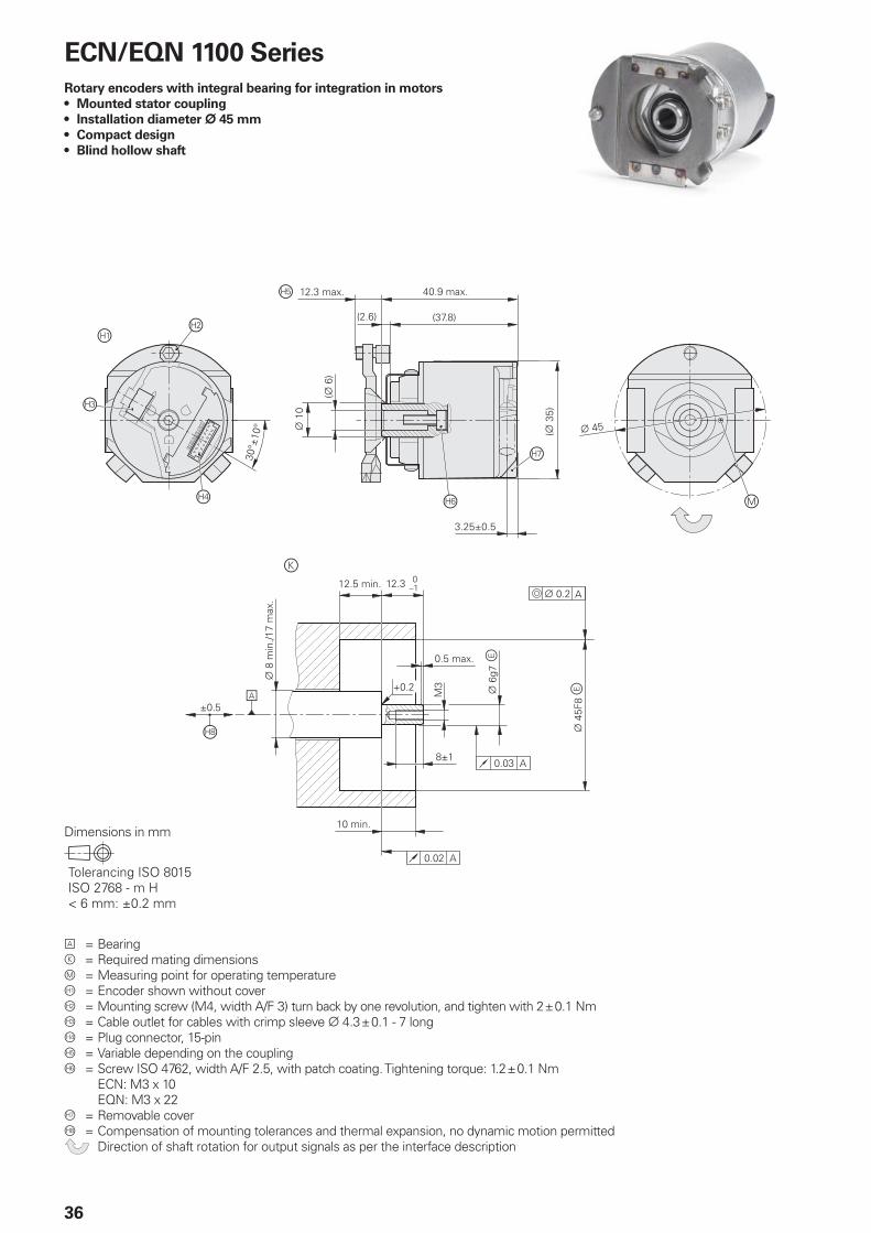
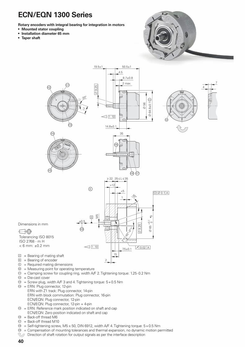
ECN/EQN 1100 Series
Rotary encoders with integral bearing for integration in motors
Mounted stator coupling
Installation diameter ¬ 45 mm
Compact design
Blind hollow shaft
•
•
•
•
A = Bearingk = Required mating dimensionsm = Measuring point for operating temperatureÀ = Encoder shown without coverÁ = Mounting screw (M4, width A/F 3) turn back by one revolution, and tighten with 2 ± 0.1 Nm = Cable outlet for cables with crimp sleeve ¬ 4.3 ± 0.1 - 7 longà = Plug connector, 15-pinÄ = Variable depending on the couplingÅ = Screw ISO 4762, width A/F 2.5, with patch coating. Tightening torque: 1.2 ± 0.1 Nm ECN: M3 x 10 EQN: M3 x 22Æ = Removable coverÇ = Compensation of mounting tolerances and thermal expansion, no dynamic motion permitted Direction of shaft rotation for output signals as per the interface description
Dimensions in mm
37
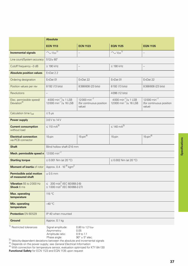
Absolute
ECN 1113 ECN 1123 EQN 1125 EQN 1135
Incremental signals » VPP1) – » VPP
1) –
Line count/System accuracy 512/± 60"
Cutoff frequency –3 dB ‡ 190 kHz – † 190 kHz –
Absolute position values EnDat 2.2
Ordering designation EnDat 01 EnDat 22 EnDat 01 EnDat 22
Position values per rev 8 192 (13 bits) 8 388 608 (23 bits) 8 192 (13 bits) 8 388 608 (23 bits)
Revolutions – 4 096 (12 bits)
Elec. permissible speed/Deviation2)
4 000 min–1/± 1 LSB12 000 min–1/± 16 LSB
12 000 min–1
(for continuous position value)
4 000 min–1/± 1 LSB12 000 min–1/± 16 LSB
12 000 min–1
(for continuous position value)
Calculation time tcal † 5 µs
Power supply 3.6 V to 14 V
Current consumption
without load† 110 mA3) † 140 mA3)
Electrical connection
via PCB connector15-pin 15-pin4) 15-pin 15-pin4)
Shaft Blind hollow shaft ¬ 6 mm
Mech. permissible speed n 12 000 min–1
Starting torque † 0.001 Nm (at 20 °C) † 0.002 Nm (at 20 °C)
Moment of inertia of rotor Approx. 0.4 · 10–6 kgm2
Permissible axial motion
of measured shaft
± 0.5 mm
Vibration 55 to 2 000 HzShock 6 ms
† 200 m/s2 (IEC 60 068-2-6)† 1 000 m/s2 (IEC 60 068-2-27)
Max. operating
temperature
115 °C
Min. operating
temperature
–40 °C
Protection EN 60 529 IP 40 when mounted
Ground Approx. 0.1 kg
1) Restricted tolerances Signal amplitude: 0.80 to 1.2 VPP
Asymmetry: 0.05 Amplitude ratio: 0.9 to 1.1 Phase angle: 90° ± 5° elec.2)
Velocity-dependent deviations between the absolute and incremental signals3)
Depends on the power supply; see General Electrical Information4)
With connection for temperature sensor, evaluation optimized for KTY 84-130Functional Safety for ECN 1123 and EQN 1135 upon request
Sp
ecifi c
ati
on
s
����
�
���������
����
���������
������������
��
���������
�
�
�
�
�
�������
����
�����������
�������
�������
�������������������
��������
���
��
�� ��
�����
�
�����
����������������
� ��
����� !"�#�$%&$'�()������()�����*���+,�����-�������
38
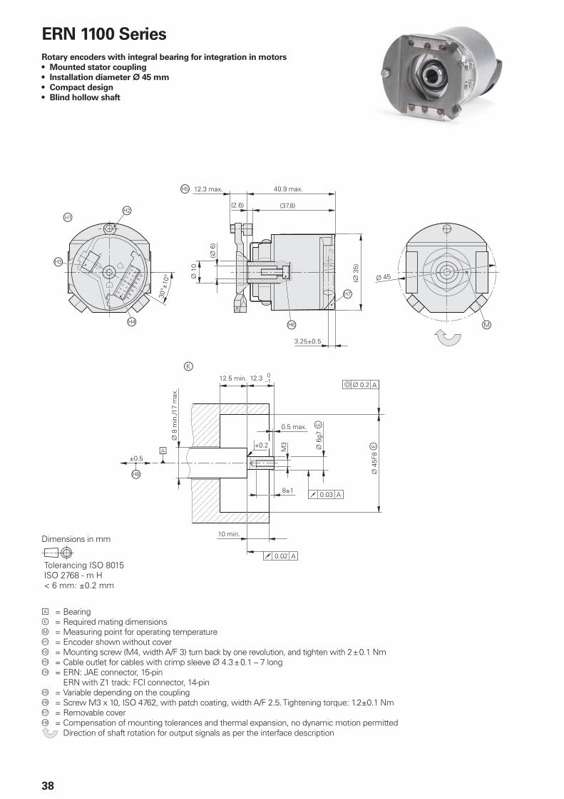
A = Bearingk = Required mating dimensionsm = Measuring point for operating temperatureÀ = Encoder shown without coverÁ = Mounting screw (M4, width A/F 3) turn back by one revolution, and tighten with 2 ± 0.1 Nm = Cable outlet for cables with crimp sleeve ¬ 4.3 ± 0.1 – 7 longà = ERN: JAE connector, 15-pin ERN with Z1 track: FCI connector, 14-pinÄ = Variable depending on the couplingÅ = Screw M3 x 10, ISO 4762, with patch coating, width A/F 2.5. Tightening torque: 1.2±0.1 NmÆ = Removable coverÇ = Compensation of mounting tolerances and thermal expansion, no dynamic motion permitted Direction of shaft rotation for output signals as per the interface description
ERN 1100 Series
Rotary encoders with integral bearing for integration in motors
Mounted stator coupling
Installation diameter ¬ 45 mm
Compact design
Blind hollow shaft
•
•
•
•
Dimensions in mm
39
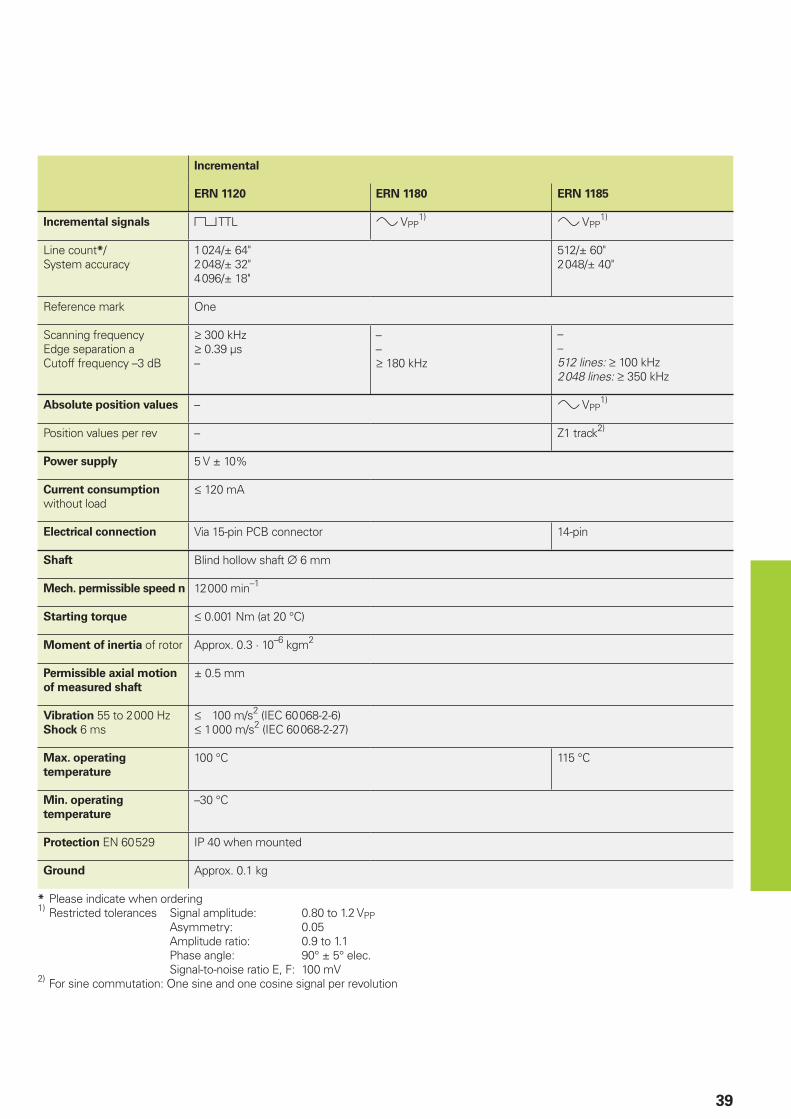
Incremental
ERN 1120 ERN 1180 ERN 1185
Incremental signals « TTL » VPP1) » VPP
1)
Line count*/System accuracy
1 024/± 64"2 048/± 32"4 096/± 18"
512/± 60"2 048/± 40"
Reference mark One
Scanning frequencyEdge separation aCutoff frequency –3 dB
‡ 300 kHz‡ 0.39 µs–
––‡ 180 kHz
––512 lines: ‡ 100 kHz2 048 lines: ‡ 350 kHz
Absolute position values – » VPP1)
Position values per rev – Z1 track2)
Power supply 5 V ± 10%
Current consumption
without load† 120 mA
Electrical connection Via 15-pin PCB connector 14-pin
Shaft Blind hollow shaft ¬ 6 mm
Mech. permissible speed n 12 000 min–1
Starting torque † 0.001 Nm (at 20 °C)
Moment of inertia of rotor Approx. 0.3 · 10–6 kgm2
Permissible axial motion
of measured shaft
± 0.5 mm
Vibration 55 to 2 000 HzShock 6 ms
† 100 m/s2 (IEC 60 068-2-6)† 1 000 m/s2 (IEC 60 068-2-27)
Max. operating
temperature
100 °C 115 °C
Min. operating
temperature
–30 °C
Protection EN 60 529 IP 40 when mounted
Ground Approx. 0.1 kg
* Please indicate when ordering1) Restricted tolerances Signal amplitude: 0.80 to 1.2 VPP Asymmetry: 0.05 Amplitude ratio: 0.9 to 1.1 Phase angle: 90° ± 5° elec. Signal-to-noise ratio E, F: 100 mV2) For sine commutation: One sine and one cosine signal per revolution
����
�� ������
��������������
�
�
�
�
�
�
�
��������
������
���
!"�#�$%&$'�()������()�����*���+,�����-�������
40
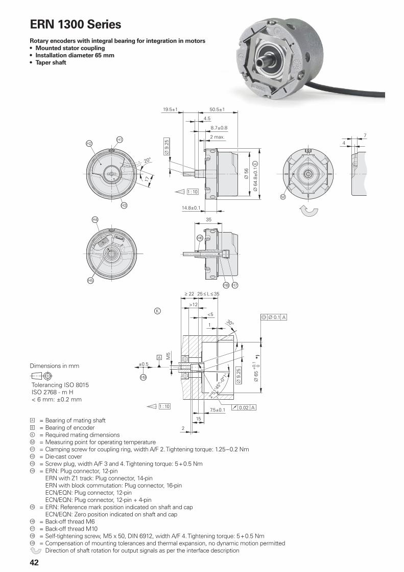
A = Bearing of mating shaftB = Bearing of encoderk = Required mating dimensionsm = Measuring point for operating temperatureÀ = Clamping screw for coupling ring, width A/F 2. Tightening torque: 1.25 - 0.2 NmÁ = Die-cast cover = Screw plug, width A/F 3 and 4. Tightening torque: 5 + 0.5 Nmà = ERN: Plug connector, 12-pin ERN with Z1 track: Plug connector, 14-pin ERN with block commutation: Plug connector, 16-pin ECN/EQN: Plug connector, 12-pin ECN/EQN: Plug connector, 12-pin + 4-pinÄ = ERN: Reference mark position indicated on shaft and cap ECN/EQN: Zero position indicated on shaft and capÅ = Back-off thread M6Æ = Back-off thread M10Ç = Self-tightening screw, M5 x 50, DIN 6912, width A/F 4. Tightening torque: 5 + 0.5 NmÈ = Compensation of mounting tolerances and thermal expansion, no dynamic motion permitted Direction of shaft rotation for output signals as per the interface description
ECN/EQN 1300 Series
Rotary encoders with integral bearing for integration in motors
Mounted stator coupling
Installation diameter 65 mm
Taper shaft
•
•
•
Dimensions in mm
41
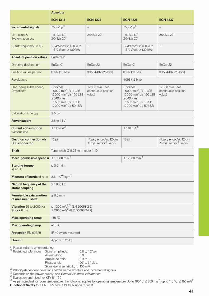
Absolute
ECN 1313 ECN 1325 EQN 1325 EQN 1337
Incremental signals » VPP1) – » VPP
1) –
Line count*/System accuracy
512/± 60"2 048/± 20"
2 048/± 20" 512/± 60"2 048/± 20"
2 048/± 20"
Cutoff frequency –3 dB 2 048 lines: ‡ 400 kHz 512 lines: ‡ 130 kHz
– 2 048 lines: ‡ 400 kHz 512 lines: ‡ 130 kHz
–
Absolute position values EnDat 2.2
Ordering designation EnDat 01 EnDat 22 EnDat 01 EnDat 22
Position values per rev 8 192 (13 bits) 33 554 432 (25 bits) 8 192 (13 bits) 33 554 432 (25 bits)
Revolutions – 4 096 (12 bits)
Elec. permissible speed/Deviation2)
512 lines: 5 000 min–1/± 1 LSB12 000 min–1/± 100 LSB2 048 lines: 1 500 min–1/± 1 LSB12 000 min–1/± 50 LSB
12 000 min–1(for continuous position value)
512 lines: 5 000 min–1/± 1 LSB12 000 min–1/± 100 LSB2 048 lines: 1 500 min–1/± 1 LSB12 000 min–1/± 50 LSB
12 000 min–1(for continuous position value)
Calculation time tcal † 5 µs
Power supply 3.6 to 14 V
Current consumption
without load† 110 mA3) † 140 mA3)
Electrical connection via
PCB connector
12-pin Rotary encoder: 12-pinTemp. sensor4): 4-pin
12-pin Rotary encoder: 12-pinTemp. sensor4): 4-pin
Shaft Taper shaft ¬ 9.25 mm; taper 1:10
Mech. permissible speed n † 15 000 min–1 † 12 000 min–1
Starting torque
at 20 °C† 0.01 Nm
Moment of inertia of rotor 2.6 · 10–6 kgm2
Natural frequency of the
stator coupling
‡ 1 800 Hz
Permissible axial motion
of measured shaft
± 0.5 mm
Vibration 55 to 2 000 HzShock 6 ms
† 300 m/s2 5) (EN 60 068-2-6)† 2 000 m/s2 (IEC 60 068-2-27)
Max. operating temp. 115 °C
Min. operating temp. –40 °C
Protection EN 60 529 IP 40 when mounted
Ground Approx. 0.25 kg
* Please indicate when ordering1)
Restricted tolerances Signal amplitude: 0.8 to 1.2 VPP Asymmetry: 0.05 Amplitude ratio: 0.9 to 1.1 Phase angle: 90° ± 5° elec. Signal-to-noise ratio E, F: 100 mV2)
Velocity-dependent deviations between the absolute and incremental signals3)
Depends on the power supply; see General Electrical Information4)
Evaluation optimized for KTY 84-1305)
As per standard for room temperature; the following applies for operating temperature Up to 100 °C: † 300 m/s2; up to 115 °C: † 150 m/s2
Functional Safety for ECN 1325 and EQN 1337 upon request
����
�� ������
��������������
�
�
�
�
�
�
�
��������
������
���
!"�#�$%&$'�()������()�����*���+,�����-�������
42
ERN 1300 Series
Rotary encoders with integral bearing for integration in motors
Mounted stator coupling
Installation diameter 65 mm
Taper shaft
•
•
•
Dimensions in mm
A = Bearing of mating shaftB = Bearing of encoderk = Required mating dimensionsm = Measuring point for operating temperatureÀ = Clamping screw for coupling ring, width A/F 2. Tightening torque: 1.25 – 0.2 NmÁ = Die-cast cover = Screw plug, width A/F 3 and 4. Tightening torque: 5 + 0.5 Nmà = ERN: Plug connector, 12-pin ERN with Z1 track: Plug connector, 14-pin ERN with block commutation: Plug connector, 16-pin ECN/EQN: Plug connector, 12-pin ECN/EQN: Plug connector, 12-pin + 4-pinÄ = ERN: Reference mark position indicated on shaft and cap ECN/EQN: Zero position indicated on shaft and capÅ = Back-off thread M6Æ = Back-off thread M10Ç = Self-tightening screw, M5 x 50, DIN 6912, width A/F 4. Tightening torque: 5 + 0.5 NmÈ = Compensation of mounting tolerances and thermal expansion, no dynamic motion permitted Direction of shaft rotation for output signals as per the interface description
43
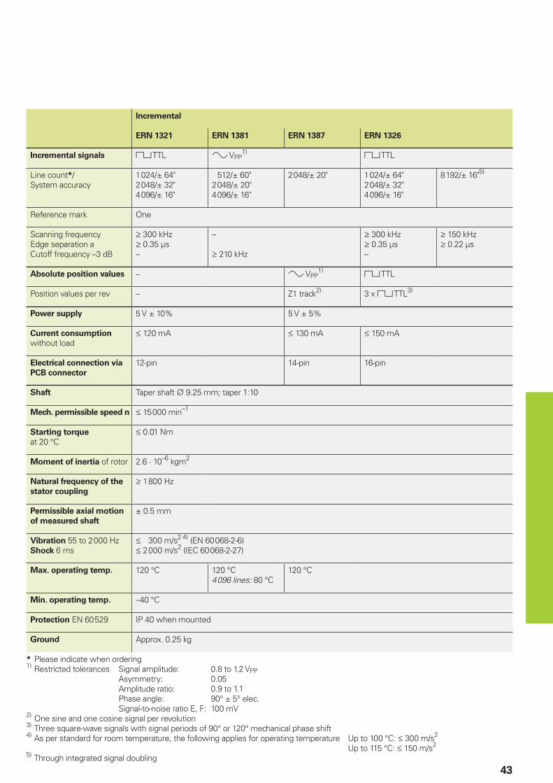
Incremental
ERN 1321 ERN 1381 ERN 1387 ERN 1326
Incremental signals « TTL » VPP1) « TTL
Line count*/System accuracy
1 024/± 64"2 048/± 32"4 096/± 16"
512/± 60"2 048/± 20"4 096/± 16"
2 048/± 20" 1 024/± 64"2 048/± 32"4 096/± 16"
8 192/± 16"5)
Reference mark One
Scanning frequencyEdge separation aCutoff frequency –3 dB
‡ 300 kHz‡ 0.35 µs–
–
‡ 210 kHz
‡ 300 kHz‡ 0.35 µs–
‡ 150 kHz‡ 0.22 µs
Absolute position values – » VPP1) « TTL
Position values per rev – Z1 track2) 3 x « TTL3)
Power supply 5 V ± 10% 5 V ± 5%
Current consumption
without load† 120 mA † 130 mA † 150 mA
Electrical connection via
PCB connector
12-pin 14-pin 16-pin
Shaft Taper shaft ¬ 9.25 mm; taper 1:10
Mech. permissible speed n † 15 000 min–1
Starting torque
at 20 °C† 0.01 Nm
Moment of inertia of rotor 2.6 · 10–6 kgm2
Natural frequency of the
stator coupling
‡ 1 800 Hz
Permissible axial motion
of measured shaft
± 0.5 mm
Vibration 55 to 2 000 HzShock 6 ms
† 300 m/s2 4) (EN 60 068-2-6)† 2 000 m/s2 (IEC 60 068-2-27)
Max. operating temp. 120 °C 120 °C4 096 lines: 80 °C
120 °C
Min. operating temp. –40 °C
Protection EN 60 529 IP 40 when mounted
Ground Approx. 0.25 kg
* Please indicate when ordering1)
Restricted tolerances Signal amplitude: 0.8 to 1.2 VPP Asymmetry: 0.05 Amplitude ratio: 0.9 to 1.1 Phase angle: 90° ± 5° elec. Signal-to-noise ratio E, F: 100 mV2)
One sine and one cosine signal per revolution3)
Three square-wave signals with signal periods of 90° or 120° mechanical phase shift4)
As per standard for room temperature, the following applies for operating temperature Up to 100 °C: † 300 m/s2
Up to 115 °C: † 150 m/s2
5) Through integrated signal doubling
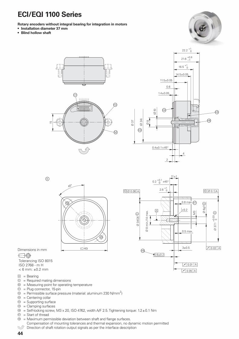
��
�
�
���
���������
���� ���
������������
�� �
��������������������
���������
������������.
�
�/���
/��
�/����
�/��
�
�
����� �
��������������������
��������
�� /��'
�
��� 0
�
/����
&$�1�������
������
��
/����� 0
/���2
��
���� 0
�������� ������ ����
������
��������������
�
/���� 0��� �
�����������
����
�����
���������
���.
����
���� 0
��� ����
���.������������
!"�#�$%&$'�()������()�����*���+,�����-�������
44
ECI/EQI 1100 Series
Rotary encoders without integral bearing for integration in motors
Installation diameter 37 mm
Blind hollow shaft
•
•
Dimensions in mm
A = Bearingk = Required mating dimensionsm = Measuring point for operating temperatureÀ = Plug connector, 15-pinÁ = Permissible surface pressure (material: aluminum 230 N/mm2) = Centering collar à = Supporting surfaceÄ = Clamping surfacesÅ = Self-locking screw, M3 x 20, ISO 4762, width A/F 2.5. Tightening torque: 1.2 ± 0.1 NmÆ = Start of threadÇ = Maximum permissible deviation between shaft and fl ange surfaces.
Compensation of mounting tolerances and thermal expansion, no dynamic motion permitted Direction of shaft rotation output signals as per the interface description
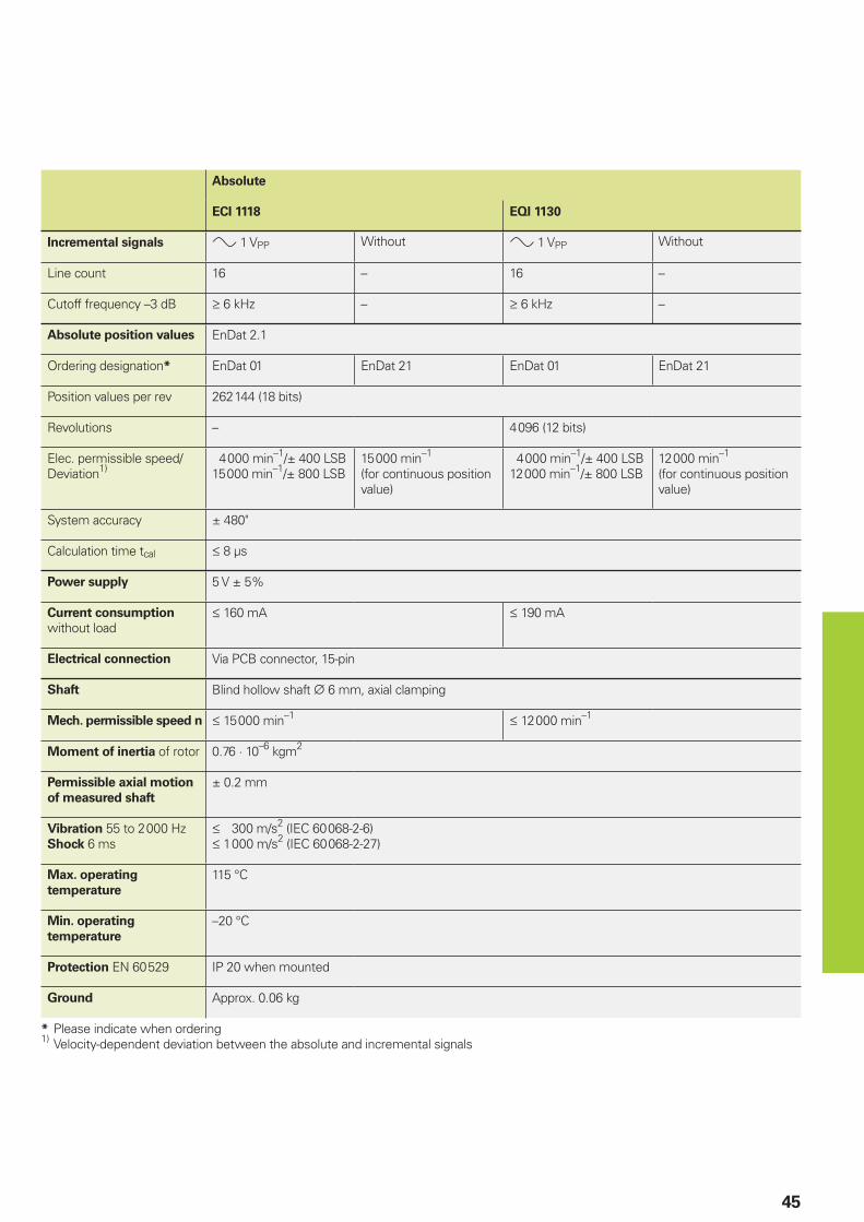
45
Absolute
ECI 1118 EQI 1130
Incremental signals » 1 VPP Without » 1 VPP Without
Line count 16 – 16 –
Cutoff frequency –3 dB ‡ 6 kHz – ‡ 6 kHz –
Absolute position values EnDat 2.1
Ordering designation* EnDat 01 EnDat 21 EnDat 01 EnDat 21
Position values per rev 262 144 (18 bits)
Revolutions – 4 096 (12 bits)
Elec. permissible speed/Deviation1)
4 000 min–1/± 400 LSB15 000 min–1/± 800 LSB
15 000 min–1
(for continuous position value)
4 000 min–1/± 400 LSB12 000 min–1/± 800 LSB
12 000 min–1
(for continuous position value)
System accuracy ± 480"
Calculation time tcal † 8 µs
Power supply 5 V ± 5%
Current consumption
without load† 160 mA † 190 mA
Electrical connection Via PCB connector, 15-pin
Shaft Blind hollow shaft ¬ 6 mm, axial clamping
Mech. permissible speed n † 15 000 min–1 † 12 000 min–1
Moment of inertia of rotor 0.76 · 10–6 kgm2
Permissible axial motion
of measured shaft
± 0.2 mm
Vibration 55 to 2 000 HzShock 6 ms
† 300 m/s2 (IEC 60 068-2-6)† 1 000 m/s2 (IEC 60 068-2-27)
Max. operating
temperature
115 °C
Min. operating
temperature
–20 °C
Protection EN 60 529 IP 20 when mounted
Ground Approx. 0.06 kg
* Please indicate when ordering1)
Velocity-dependent deviation between the absolute and incremental signals
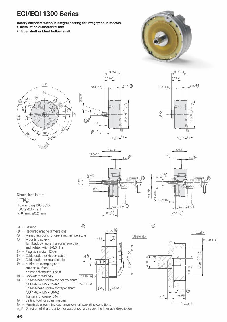
���� 0
�
���������
3��
��
3���
���� 0
����� 0
�����
�
�
,���� �
�
������
�� �������
��������������������������
����
���������
������
�������� �
��
���
�����
�
�
�
�������
�����������
����
��
����
�
�
����
��������
������
������
�����
����
�����
������
��
������
��� 0
��-���
!����
3��
����� 0
�
�
�
�
���
� ����������������
�����������
�����������
��
����
�
�
�����
��
����
.��
����
���������
��
���
���
���
��
�����
���
�
�
�
�
�
����
���
�� �������
��������������������������
�������������������
�� �������
���������
�� �������
���������
�
!"�#�$%&$'�()������()�����*���+,�����-�������
46
ECI/EQI 1300 Series
Rotary encoders without integral bearing for integration in motors
Installation diameter 65 mm
Taper shaft or blind hollow shaft
•
•
Dimensions in mm
A = Bearingk = Required mating dimensionsm = Measuring point for operating temperatureÀ = Mounting screw
Turn back by more than one revolution, and tighten with 2-0.5 Nm
Á = Plug connector, 12-pin = Cable outlet for ribbon cableà = Cable outlet for round cableÄ = Minimum clamping and
support surface; a closed diameter is best
Å = Back-off thread M6Æ = Cheese-head screw for hollow shaft:
ISO 4762 – M5 x 35-A2Cheese-head screw for taper shaft:ISO 4762 – M5 x 50-A2 Tightening torque: 5 Nm
Ç = Setting tool for scanning gapÈ = Permissible scanning gap range over all operating conditions Direction of shaft rotation for output signals as per the interface description
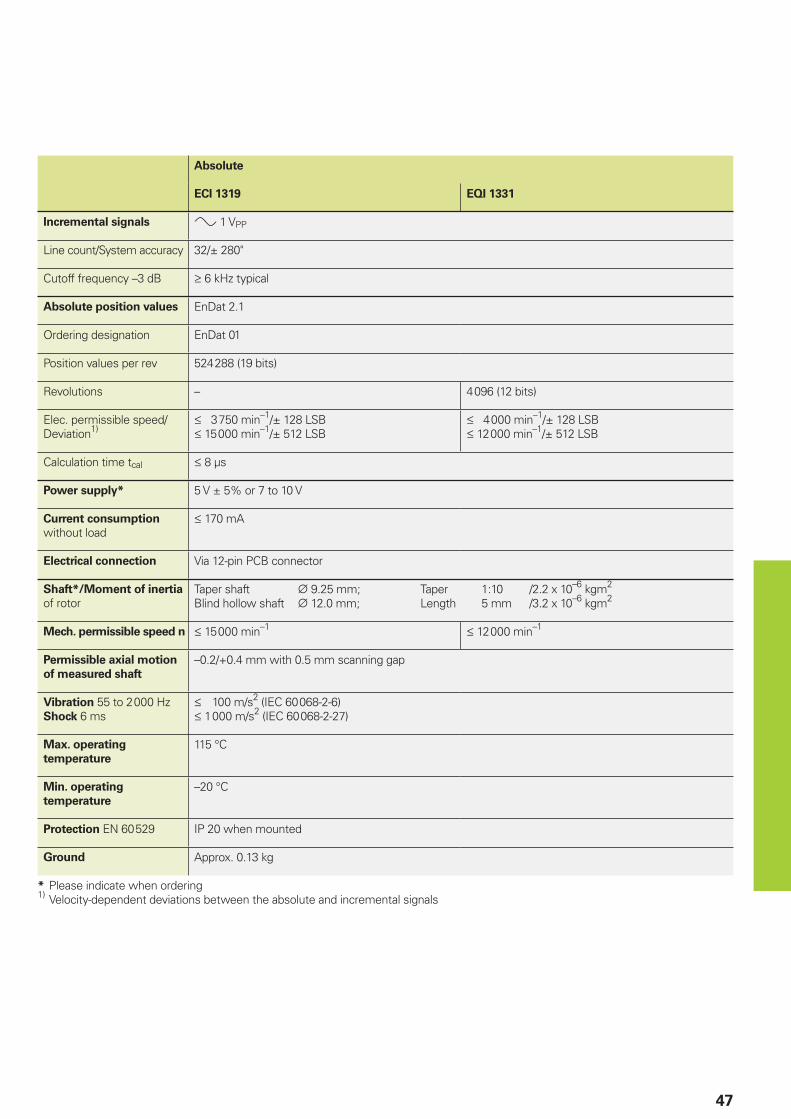
47
Absolute
ECI 1319 EQI 1331
Incremental signals » 1 VPP
Line count/System accuracy 32/± 280"
Cutoff frequency –3 dB ‡ 6 kHz typical
Absolute position values EnDat 2.1
Ordering designation EnDat 01
Position values per rev 524 288 (19 bits)
Revolutions – 4 096 (12 bits)
Elec. permissible speed/Deviation1)
† 3 750 min–1/± 128 LSB† 15 000 min–1/± 512 LSB
† 4 000 min–1/± 128 LSB† 12 000 min–1/± 512 LSB
Calculation time tcal † 8 µs
Power supply* 5 V ± 5% or 7 to 10 V
Current consumption
without load† 170 mA
Electrical connection Via 12-pin PCB connector
Shaft*/Moment of inertia
of rotorTaper shaft ¬ 9.25 mm; Taper 1:10 /2.2 x 10–6 kgm2
Blind hollow shaft ¬ 12.0 mm; Length 5 mm /3.2 x 10–6 kgm2
Mech. permissible speed n † 15 000 min–1 † 12 000 min–1
Permissible axial motion
of measured shaft
–0.2/+0.4 mm with 0.5 mm scanning gap
Vibration 55 to 2 000 HzShock 6 ms
† 100 m/s2 (IEC 60 068-2-6)† 1 000 m/s2 (IEC 60 068-2-27)
Max. operating
temperature
115 °C
Min. operating
temperature
–20 °C
Protection EN 60 529 IP 20 when mounted
Ground Approx. 0.13 kg
* Please indicate when ordering1)
Velocity-dependent deviations between the absolute and incremental signals
!"�#�$%&$'�()������()�����*���+,�����-�������
48
ERO 1200 Series
Rotary encoders without integral bearing for integration in motors
Installation diameter 52 mm
Hollow through shaft
•
•
Dimensions in mm
A = Bearingk = Required mating dimensionsÀ = Disk/hub assemblyÁ = Offset screwdriver ISO 2936 – 2.5 (I2 shortened) Direction of shaft rotation for output signals as per the
interface description
D
¬ 10h6 e
¬ 12h6 e
Z a f c
ERO 1225 1 024 0.6 ± 0.2 ¬ 0.05 ¬ 0.02
2 048 0.2 ± 0.05
ERO 1285 1 0242 048
0.2 ± 0.03 ¬ 0.03 ¬ 0.02
49
Incremental
ERO 1225 ERO 1285
Incremental signals « TTL » 1 VPP
Line count* 1 0242 048
System accuracy1)/Accuracy of the graduation2)
1 024 lines: ± 92"/± 6"2 048 lines: ± 73"/± 6"
1 024 lines: ± 67"/± 6"2 048 lines: ± 60"/± 6"
Reference mark One
Scanning frequencyEdge separation aCutoff frequency –3 dB
† 300 kHz‡ 0.39 µs–
––‡ 180 kHz typical
Power supply 5 V ± 10%
Current consumption
without load† 150 mA
Electrical connection Via 12-pin PCB connector
Shaft* Hollow through shaft ¬ 10 mm or ¬ 12 mm
Moment of inertia of rotor Shaft ¬ 10 mm: 2.2 · 10–6 kgm2
Shaft ¬ 12 mm: 2.15 · 10–6 kgm2
Mech. permissible speed n † 25 000 min–1
Permissible axial motion
of measured shaft
1 024 lines: ± 0.2 mm2 048 lines: ± 0.05 mm
± 0.03 mm
Vibration 55 to 2 000 HzShock 6 ms
† 100 m/s2 (IEC 60 068-2-6)† 1 000 m/s2 (IEC 60 068-2-27)
Max. operating
temperature
100 °C
Min. operating
temperature
–40 °C
Protection EN 60 529 IP 00
Ground Approx. 0.07 kg
* Please indicate when ordering1) Before installation. Additional errors caused by mounting inaccuracy and inaccuracy from the bearing of the drive shaft are not included.2) For other errors, see Measuring Accuracy
!"�#�$%&$'�()������()�����*���+,�����-�������
50
ERO 1300 Series
Rotary encoders without integral bearing
for integration in motors
Installation diameter 75 mm
Hollow through shaft
•
•
Dimensions in mm
ERO 1324
ERO 1384
D
¬ 20h6 e
¬ 30h6 e
a f c
ERO 1324 0.2–0.1 ¬ 0.05 ¬ 0.02
ERO 1384 0.15 ± 0.04 ¬ 0.03 ¬ 0.02
A = Bearingk = Required mating dimensionsÀ = Disk/hub assembly Direction of shaft rotation for output signals
as per the interface description
51
Incremental
ERO 1324 ERO 1384
Incremental signals « TTL » 1 VPP
Line count* 1 0242 0485 000
System accuracy1)/Accuracy of the graduation2)
1 024 lines: ± 72"/± 15"2 048 lines: ± 53"/± 5"5 000 lines: ± 42"/± 3.5"
1 024 lines: ± 47"/± 15"2 048 lines: ± 40.5"/± 5"5 000 lines: ± 37"/± 3.5"
Reference mark One
Scanning frequencyEdge separation aCutoff frequency –3 dB
† 400 kHz‡ 0.29 µs–
––‡ 180 kHz
Power supply 5 V ± 10%
Current consumption
without load† 160 mA † 150 mA
Electrical connection Via 12-pin PCB connector(adapter cable ID 295 545-xx)
Via 12-pin PCB connector(adapter cable ID 372 164-xx)
Shaft* Hollow through shaft ¬ 20 mm or ¬ 30 mm
Moment of inertia of rotor Shaft ¬ 20 mm: 26 · 10–6 kgm2
Shaft ¬ 30 mm: 35 · 10–6 kgm2
Mech. permissible speed n † 16 000 min–1
Permissible axial motion
of measured shaft
± 0.05 mm ± 0.04 mm
Vibration 55 to 2 000 HzShock 6 ms
† 100 m/s2 (IEC 60 068-2-6)† 1 000 m/s2 (IEC 60 068-2-27)
Max. operating
temperature
70 °C 85 °C
Min. operating
temperature
0 °C
Protection EN 60 529 IP 00
Ground Approx. 0.2 kg
* Please indicate when ordering1) Before installation. Additional errors caused by mounting inaccuracy and inaccuracy from the bearing of the drive shaft are not included.2) For other errors, see Measuring Accuracy
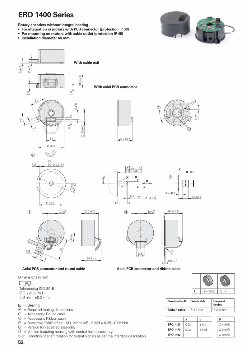
�������
� ������
������
�
�
��
�.�
�����"��
��������
��
������
��
���������
��
�
����
���
�����
��� ���
���
��������
� �
��������
�
� 0�
�����1��
0
� �
�����������
������
�����
�
.
����� 0�
�
��
��������
��
�����
�����
#
�� �� �
!"�#�$%&$'�()������()�����*���+,�����-�������
52
Dimensions in mm
a b D
ERO 1420 0.03 ± 0.1 ¬ 4h6 e
ERO 1470 0.02 ± 0.05 ¬ 6h6 e
ERO 1480 ¬ 8h6 e
ERO 1400 Series
Rotary encoders without integral bearing
For integration in motors with PCB connector (protection IP 00)
For mounting on motors with cable outlet (protection IP 40)
Installation diameter 44 mm
•
•
•
With cable exit
With axial PCB connector
Axial PCB connector and round cable Axial PCB connector and ribbon cable
A = Bearingk = Required mating dimensionsÔ = Accessory: Round cableÕ = Accessory: Ribbon cableÀ = Setscrew, 2x90° offset, M3, width A/F 1.5 Md = 0.25 ±0.05 NmÁ = Version for repeated assembly = Version featuring housing with central hole (accessory) Direction of shaft rotation for output signals as per the interface description
Bend radius R Fixed cable Frequent
fl exing
Ribbon cable R ‡ 2 mm R ‡ 10 mm
L 13+4.5/–3 10 min.
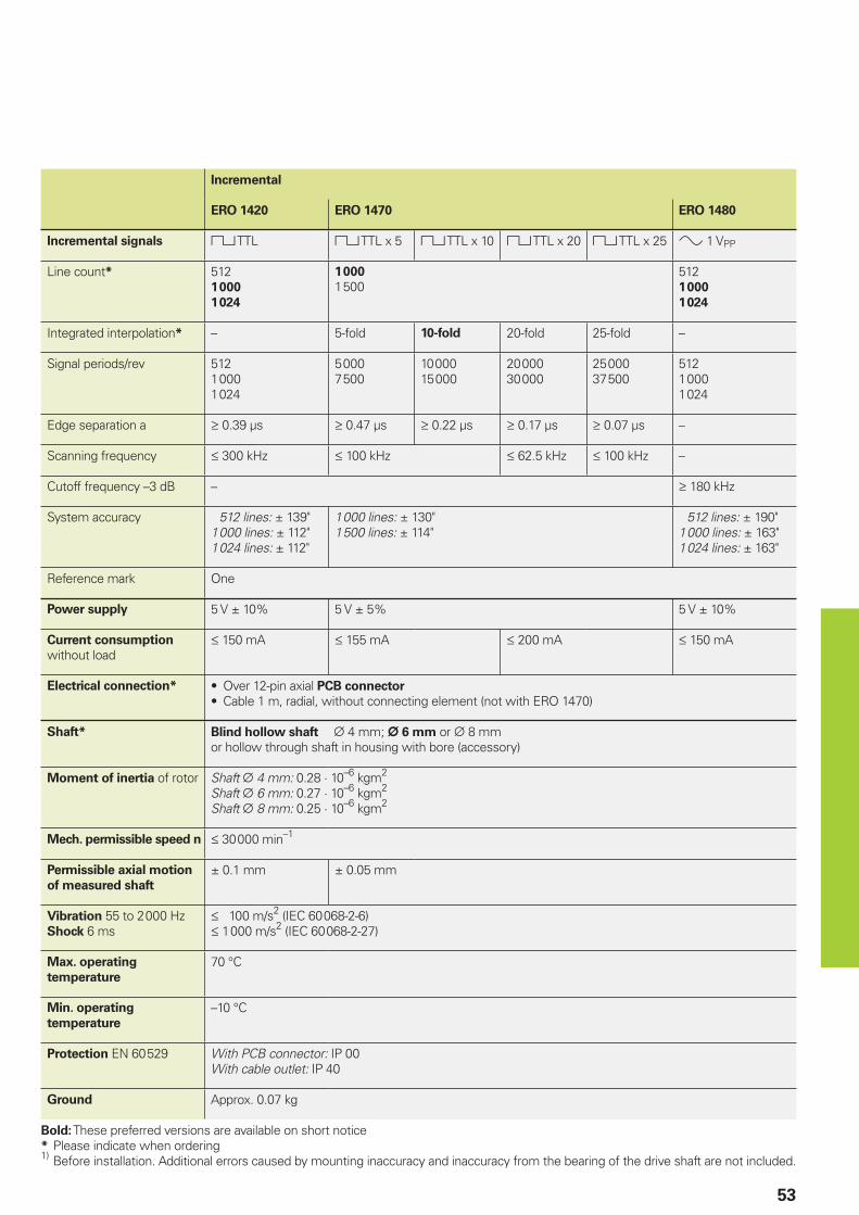
53
Incremental
ERO 1420 ERO 1470 ERO 1480
Incremental signals « TTL « TTL x 5 « TTL x 10 « TTL x 20 « TTL x 25 » 1 VPP
Line count* 5121 000
1 024
1 000
1 5005121 000
1 024
Integrated interpolation* – 5-fold 10-fold 20-fold 25-fold –
Signal periods/rev 5121 0001 024
5 0007 500
10 00015 000
20 00030 000
25 00037 500
5121 0001 024
Edge separation a ‡ 0.39 µs ‡ 0.47 µs ‡ 0.22 µs ‡ 0.17 µs ‡ 0.07 µs –
Scanning frequency † 300 kHz † 100 kHz † 62.5 kHz † 100 kHz –
Cutoff frequency –3 dB – ‡ 180 kHz
System accuracy 512 lines: ± 139"1 000 lines: ± 112"1 024 lines: ± 112"
1 000 lines: ± 130"1 500 lines: ± 114"
512 lines: ± 190"1 000 lines: ± 163"1 024 lines: ± 163"
Reference mark One
Power supply 5 V ± 10% 5 V ± 5% 5 V ± 10%
Current consumption
without load† 150 mA † 155 mA † 200 mA † 150 mA
Electrical connection* Over 12-pin axial PCB connector
Cable 1 m, radial, without connecting element (not with ERO 1470)••
Shaft* Blind hollow shaft ¬ 4 mm; ¬ 6 mm or ¬ 8 mm or hollow through shaft in housing with bore (accessory)
Moment of inertia of rotor Shaft ¬ 4 mm: 0.28 · 10–6 kgm2
Shaft ¬ 6 mm: 0.27 · 10–6 kgm2
Shaft ¬ 8 mm: 0.25 · 10–6 kgm2
Mech. permissible speed n † 30 000 min–1
Permissible axial motion
of measured shaft
± 0.1 mm ± 0.05 mm
Vibration 55 to 2 000 HzShock 6 ms
† 100 m/s2 (IEC 60 068-2-6)† 1 000 m/s2 (IEC 60 068-2-27)
Max. operating
temperature
70 °C
Min. operating
temperature
–10 °C
Protection EN 60 529 With PCB connector: IP 00With cable outlet: IP 40
Ground Approx. 0.07 kg
Bold: These preferred versions are available on short notice* Please indicate when ordering1) Before installation. Additional errors caused by mounting inaccuracy and inaccuracy from the bearing of the drive shaft are not included.
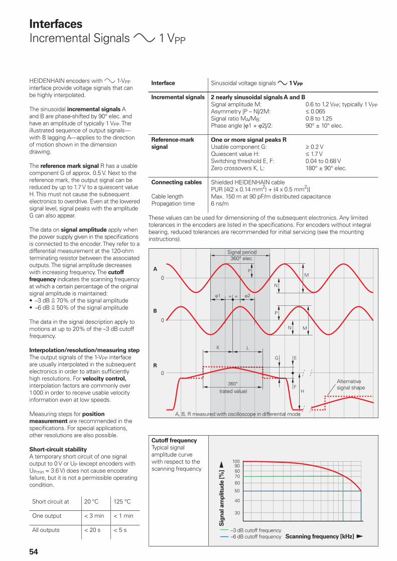
54
Interfaces
Incremental Signals » 1 VPP
Signal period360° elec.
(rated value)
A, B, R measured with oscilloscope in differential mode
Cutoff frequency
Typical signal amplitude curve with respect to the scanning frequency
Sig
nal am
plitu
de [%
]
Scanning frequency [kHz]–3 dB cutoff frequency–6 dB cutoff frequency
HEIDENHAIN encoders with » 1-VPP interface provide voltage signals that can be highly interpolated.
The sinusoidal incremental signals A and B are phase-shifted by 90° elec. and have an amplitude of typically 1 VPP. The illustrated sequence of output signals—with B lagging A—applies to the direction of motion shown in the dimension drawing.
The reference mark signal R has a usable component G of approx. 0.5 V. Next to the reference mark, the output signal can be reduced by up to 1.7 V to a quiescent value H. This must not cause the subsequent electronics to overdrive. Even at the lowered signal level, signal peaks with the amplitude G can also appear.
The data on signal amplitude apply when the power supply given in the specifi cations is connected to the encoder. They refer to a differential measurement at the 120-ohm terminating resistor between the associated outputs. The signal amplitude decreases with increasing frequency. The cutoff
frequency indicates the scanning frequency at which a certain percentage of the original signal amplitude is maintained:
–3 dB ƒ 70% of the signal amplitude–6 dB ƒ 50% of the signal amplitude
The data in the signal description apply to motions at up to 20% of the –3 dB cutoff frequency.
Interpolation/resolution/measuring step
The output signals of the 1-VPP interface are usually interpolated in the subsequent electronics in order to attain suffi ciently high resolutions. For velocity control, interpolation factors are commonly over 1 000 in order to receive usable velocity information even at low speeds.
Measuring steps for position
measurement are recommended in the specifi cations. For special applications, other resolutions are also possible.
Short-circuit stability
A temporary short circuit of one signal output to 0 V or UP (except encoders with UPmin = 3.6 V) does not cause encoder failure, but it is not a permissible operating condition.
Short circuit at 20 °C 125 °C
One output < 3 min < 1 min
All outputs < 20 s < 5 s
••
Interface Sinusoidal voltage signals » 1 VPP
Incremental signals 2 nearly sinusoidal signals A and B
Signal amplitude M: 0.6 to 1.2 VPP; typically 1 VPPAsymmetry |P – N|/2M: † 0.065Signal ratio MA/MB: 0.8 to 1.25Phase angle |ϕ1 + ϕ2|/2: 90° ± 10° elec.
Reference-mark
signal
One or more signal peaks R
Usable component G: ‡ 0.2 VQuiescent value H: † 1.7 VSwitching threshold E, F: 0.04 to 0.68 VZero crossovers K, L: 180° ± 90° elec.
Connecting cables
Cable lengthPropagation time
Shielded HEIDENHAIN cablePUR [4(2 x 0.14 mm2) + (4 x 0.5 mm2)]Max. 150 m at 90 pF/m distributed capacitance6 ns/m
These values can be used for dimensioning of the subsequent electronics. Any limited tolerances in the encoders are listed in the specifi cations. For encoders without integral bearing, reduced tolerances are recommended for initial servicing (see the mounting instructions).
Alternative signal shape
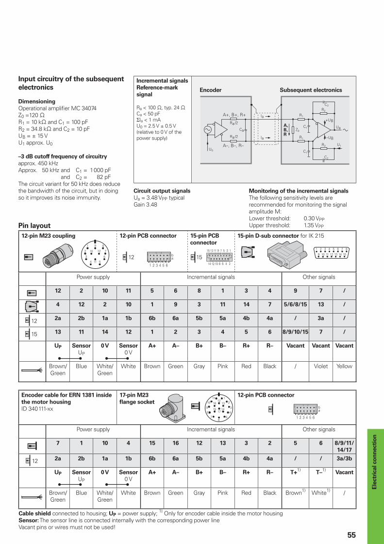
� � � � �
�4
�� � �� � � �
����������
12 15
� � � � �
�4
12
15
12
55
Pin layout
12-pin M23 coupling 12-pin PCB connector 15-pin PCB
connector
15-pin D-sub connector for IK 215
Power supply Incremental signals Other signals
12 2 10 11 5 6 8 1 3 4 9 7 /
4 12 2 10 1 9 3 11 14 7 5/6/8/15 13 /
2a 2b 1a 1b 6b 6a 5b 5a 4b 4a / 3a /
13 11 14 12 1 2 3 4 5 6 8/9/10/15 7 /
UP Sensor
UP
0 V Sensor
0 VA+ A– B+ B– R+ R– Vacant Vacant Vacant
Brown/Green
Blue White/Green
White Brown Green Gray Pink Red Black / Violet Yellow
Encoder cable for ERN 1381 inside
the motor housing
ID 340 111-xx
17-pin M23
fl ange socket
12-pin PCB connector
Power supply Incremental signals Other signals
7 1 10 4 15 16 12 13 3 2 5 6 8/9/11/
14/17
2a 2b 1a 1b 6b 6a 5b 5a 4b 4a / / 3a/3b
UP Sensor
UP
0 V Sensor
0 VA+ A– B+ B– R+ R– T+
1)T–
1)Vacant
Brown/Green
Blue White/Green
White Brown Green Gray Pink Red Black Brown1) White1) /
Cable shield connected to housing; UP = power supply; 1) Only for encoder cable inside the motor housingSensor: The sensor line is connected internally with the corresponding power lineVacant pins or wires must not be used!
Ele
ctr
ical co
nn
ecti
on
Input circuitry of the subsequent
electronics
Dimensioning
Operational amplifi er MC 34074Z0 =120 −R1 = 10 k− and C1 = 100 pFR2 = 34.8 k− and C2 = 10 pFUB = ± 15 VU1 approx. U0
–3 dB cutoff frequency of circuitry
approx. 450 kHzApprox. 50 kHz and C1 = 1 000 pF and C2 = 82 pFThe circuit variant for 50 kHz does reduce the bandwidth of the circuit, but in doing so it improves its noise immunity.
Incremental signals
Reference-mark
signal
Ra < 100 −, typ. 24 −Ca < 50 pFΣIa < 1 mAU0 = 2.5 V ± 0.5 V(relative to 0 V of the power supply)
Encoder Subsequent electronics
Circuit output signals
Ua = 3.48 VPP typicalGain 3.48
Monitoring of the incremental signals
The following sensitivity levels are recommended for monitoring the signal amplitude M:Lower threshold: 0.30 VPPUpper threshold: 1.35 VPP
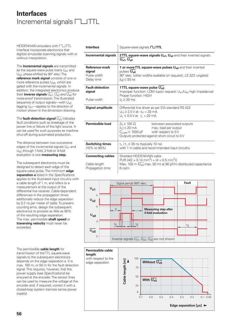
���
5)
�� ��� ��� ��� ��� �� ���
�
��
�
���
�
����
56
Interfaces
Incremental signals « TTL
HEIDENHAIN encoders with « TTL interface incorporate electronics that digitize sinusoidal scanning signals with or without interpolation.
The incremental signals are transmitted as the square-wave pulse trains Ua1 and Ua2, phase-shifted by 90° elec. The reference mark signal consists of one or more reference pulses Ua0, which are gated with the incremental signals. In addition, the integrated electronics produce their inverse signals , £ and ¤ for noise-proof transmission. The illustrated sequence of output signals—with Ua2 lagging Ua1—applies to the direction of motion shown in the dimension drawing.
The fault-detection signal ¥ indicates fault conditions such as breakage of the power line or failure of the light source. It can be used for such purposes as machine shut-off during automated production.
The distance between two successive edges of the incremental signals Ua1 and Ua2 through 1-fold, 2-fold or 4-fold evaluation is one measuring step.
The subsequent electronics must be designed to detect each edge of the square-wave pulse. The minimum edge
separation a listed in the Specifi cations applies to the illustrated input circuitry with a cable length of 1 m, and refers to a measurement at the output of the differential line receiver. Cable-dependent differences in the propagation times additionally reduce the edge separation by 0.2 ns per meter of cable. To prevent counting error, design the subsequent electronics to process as little as 90% of the resulting edge separation.The max. permissible shaft speed or traversing velocity must never be exceeded.
The permissible cable length for transmission of the TTL square-wave signals to the subsequent electronics depends on the edge separation a. It is max. 100 m, or 50 m for the fault detection signal. This requires, however, that the power supply (see Specifi cations) be ensured at the encoder. The sensor lines can be used to measure the voltage at the encoder and, if required, correct it with a closed-loop system (remote sense power supply).
Interface Square-wave signals « TTL
Incremental signals 2 TTL square-wave signals Ua1, Ua2 and their inverted signals , £
Reference-mark
signal
Pulse widthDelay time
1 or more TTL square-wave pulses Ua0 and their inverted pulses ¤90° elec. (other widths available on request); LS 323: ungated|td| † 50 ns
Fault-detection
signal
Pulse width
1 TTL square-wave pulse ¥Improper function: LOW (upon request: Ua1/Ua2 high impedance)Proper function: HIGHtS ‡ 20 ms
Signal amplitude Differential line driver as per EIA standard RS 422UH ‡ 2.5 V at –IH = 20 mAUL † 0.5 V at IL = 20 mA
Permissible load Z0 ‡ 100 − between associated outputs|IL| † 20 mA max. load per outputCLoad † 1000 pF with respect to 0 VOutputs protected against short circuit to 0 V
Switching times
(10% to 90%)t+ / t– † 30 ns (typically 10 ns)with 1 m cable and recommended input circuitry
Connecting cables
Cable lengthPropagation time
Shielded HEIDENHAIN cablePUR [4(2 × 0.14 mm2) + (4 × 0.5 mm2)]Max. 100 m (¥ max. 50 m) at 90 pF/m distributed capacitance6 ns/m
Signal period 360° elec. Fault
Measuring step after
4-fold evaluation
Inverse signals , £, ¤ are not shown
Permissible cable
length
with respect to the edge separation
Cab
le len
gth
[m
]
Edge separation [µs]
Without ¥
With ¥
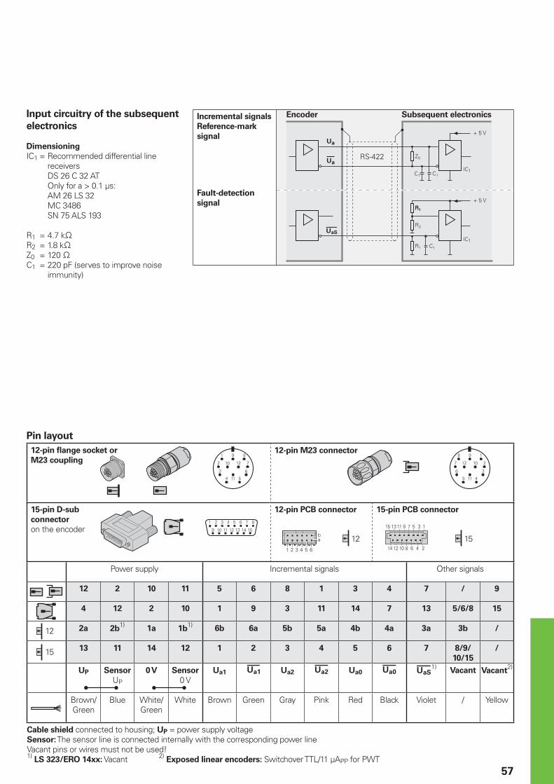
� � � � �
�4
�� � �� � � �
����������
12
15
1512
57
Pin layout
12-pin fl ange socket or
M23 coupling
12-pin M23 connector
15-pin D-sub
connector
on the encoder
12-pin PCB connector 15-pin PCB connector
Power supply Incremental signals Other signals
12 2 10 11 5 6 8 1 3 4 7 / 9
4 12 2 10 1 9 3 11 14 7 13 5/6/8 15
2a 2b1)
1a 1b1)
6b 6a 5b 5a 4b 4a 3a 3b /
13 11 14 12 1 2 3 4 5 6 7 8/9/
10/15
/
UP Sensor
UP
0 V Sensor
0 VUa1 Ua2 £ Ua0 ¤ ¥1)
Vacant Vacant2)
Brown/Green
Blue White/Green
White Brown Green Gray Pink Red Black Violet / Yellow
Cable shield connected to housing; UP = power supply voltageSensor: The sensor line is connected internally with the corresponding power lineVacant pins or wires must not be used!1) LS 323/ERO 14xx: Vacant 2) Exposed linear encoders: Switchover TTL/11 µAPP for PWT
Input circuitry of the subsequent
electronics
Dimensioning
IC1 = Recommended differential line receivers
DS 26 C 32 AT Only for a > 0.1 µs: AM 26 LS 32 MC 3486 SN 75 ALS 193
R1 = 4.7 k−R2 = 1.8 k−Z0 = 120 −C1 = 220 pF (serves to improve noise
immunity)
Incremental signals
Reference-mark
signal
Fault-detection
signal
Encoder Subsequent electronics
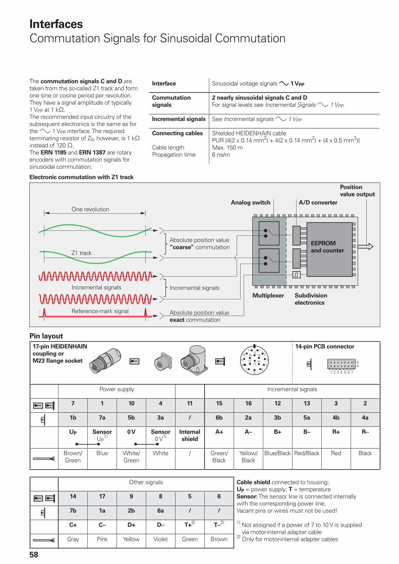
� � � � �
�4
58
Interfaces
Commutation Signals for Sinusoidal Commutation
The commutation signals C and D are taken from the so-called Z1 track and form one sine or cosine period per revolution. They have a signal amplitude of typically 1 VPP at 1 k−.The recommended input circuitry of the subsequent electronics is the same as for the » 1 VPP interface. The required terminating resistor of Z0, however, is 1 k− instead of 120 −.The ERN 1185 and ERN 1387 are rotary encoders with commutation signals for sinusoidal commutation.
Interface Sinusoidal voltage signals » 1 VPP
Commutation
signals
2 nearly sinusoidal signals C and D
For signal levels see Incremental Signals » 1 VPP
Incremental signals See Incremental signals » 1 VPP
Connecting cables
Cable lengthPropagation time
Shielded HEIDENHAIN cablePUR [4(2 x 0.14 mm2) + 4(2 x 0.14 mm2) + (4 x 0.5 mm2)]Max. 150 m6 ns/m
Electronic commutation with Z1 track
One revolution
Z1 track
Incremental signals
Reference-mark signal
Absolute position value “coarse” commutation
Absolute position value exact commutation
Incremental signals
Analog switch
Position
value output
A/D converter
EEPROM
and counter
Multiplexer Subdivision
electronics
Pin layout
17-pin HEIDENHAIN
coupling or
M23 fl ange socket
14-pin PCB connector
Power supply Incremental signals
7 1 10 4 11 15 16 12 13 3 2
1b 7a 5b 3a / 6b 2a 3b 5a 4b 4a
UP Sensor
UP1)
0 V Sensor
0 V1)Internal
shield
A+ A– B+ B– R+ R–
Brown/Green
Blue White/Green
White / Green/Black
Yellow/Black
Blue/Black Red/Black Red Black
Other signals Cable shield connected to housing;UP = power supply; T = temperatureSensor: The sensor line is connected internally with the corresponding power line.Vacant pins or wires must not be used!
1) Not assigned if a power of 7 to 10 V is supplied via motor-internal adapter cable
2) Only for motor-internal adapter cables
14 17 9 8 5 6
7b 1a 2b 6a / /
C+ C– D+ D– T+2)
T–2)
Gray Pink Yellow Violet Green Brown
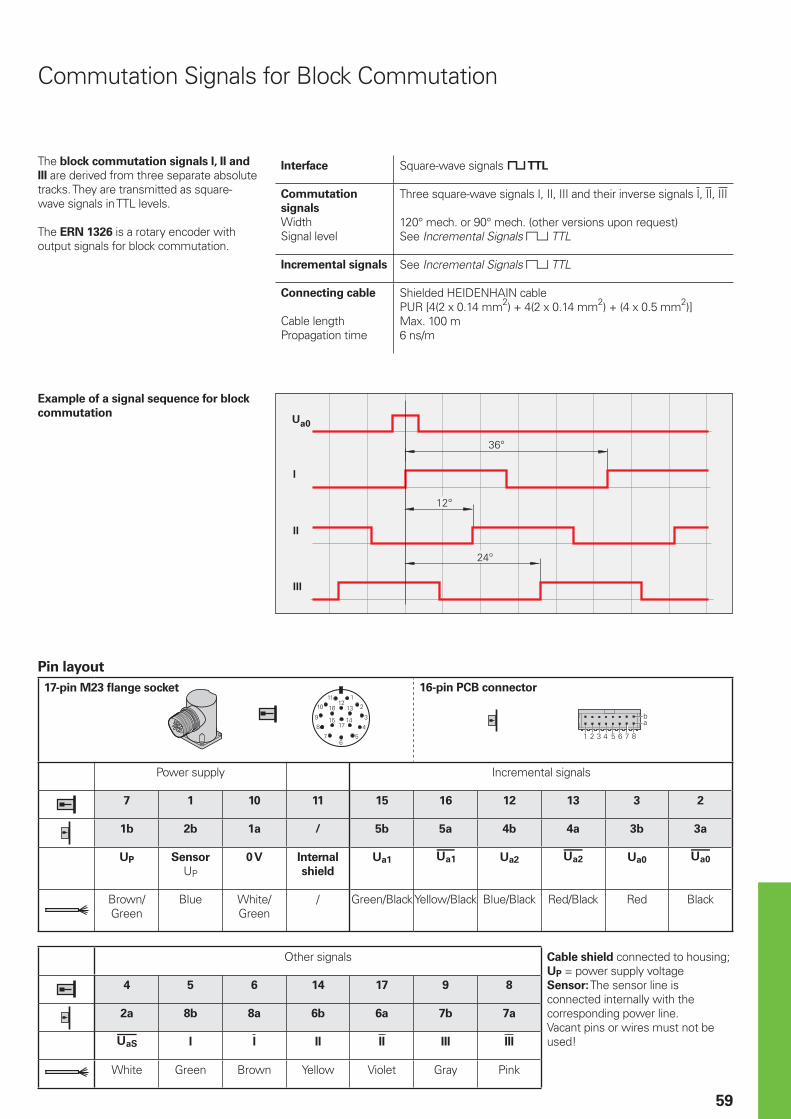
� �
��
�
��
���
���
���
� � � � � �
�4
59
Commutation Signals for Block Commutation
The block commutation signals I, II and
III are derived from three separate absolute tracks. They are transmitted as square-wave signals in TTL levels.
The ERN 1326 is a rotary encoder with output signals for block commutation.
Interface Square-wave signals « TTL
Commutation
signals
WidthSignal level
Three square-wave signals I, II, III and their inverse signals I, II, III
120° mech. or 90° mech. (other versions upon request)See Incremental Signals « TTL
Incremental signals See Incremental Signals « TTL
Connecting cable
Cable lengthPropagation time
Shielded HEIDENHAIN cablePUR [4(2 x 0.14 mm2) + 4(2 x 0.14 mm2) + (4 x 0.5 mm2)]Max. 100 m6 ns/m
Example of a signal sequence for block
commutation
Pin layout
17-pin M23 fl ange socket 16-pin PCB connector
Power supply Incremental signals
7 1 10 11 15 16 12 13 3 2
1b 2b 1a / 5b 5a 4b 4a 3b 3a
UP Sensor
UP
0 V Internal
shield
Ua1 Ua2 £ Ua0 ¤
Brown/Green
Blue White/Green
/ Green/BlackYellow/Black Blue/Black Red/Black Red Black
Other signals Cable shield connected to housing;UP = power supply voltageSensor: The sensor line is connected internally with the corresponding power line.Vacant pins or wires must not be used!
4 5 6 14 17 9 8
2a 8b 8a 6b 6a 7b 7a
¥ I I II II III III
White Green Brown Yellow Violet Gray Pink
������������������ ����� �����
60
Interfaces
Absolute position values
The EnDat interface is a digital, bidirectional interface for encoders. It is capable of transmitting position values from both absolute and—with EnDat 2.2—incremental encoders, as well as reading and updating information stored in the encoder, or of saving new information. Thanks to the serial transmission method, only four
signal lines are required. The data is transmitted in synchronism with the CLOCK signal from the subsequent electronics. The type of transmission (position values, parameters, diagnostics, etc.) is selected through mode commands that the subsequent electronics send to the encoder.
Clock frequency and cable length
Without propagation-delay compensation, the clock frequency—depending on the cable length—is variable between 100 kHz and 2 MHz.
Because large cable lengths and high clock frequencies increase the propagation time to the point that they can disturb the unambiguous assignment of data, the delay can be measured in a test run and then compensated. With this propagation-
delay compensation in the subsequent electronics, clock frequencies up to 16 MHz at cable lengths up to a maximum of 100 m (fCLK † 8 MHz) are possible. The maximum clock frequency is mainly determined by the cables and connecting elements used. To ensure proper function at clock frequencies above 2 MHz, use only original ready-made HEIDENHAIN cables.
Interface EnDat serial bidirectional
Data transfer Absolute position values, parameters and additional information
Data input Differential line receiver according to EIA standard RS 485 for the signals CLOCK, CLOCK, DATA and DATA
Data output Differential line driver according to EIA standard RS 485 for the signals DATA and DATA
Code Pure binary code
Position values Ascending during traverse in direction of arrow (see dimensions of the encoders)
Incremental signals » 1 VPP (see Incremental signals 1 VPP) depending on unit
Connecting cables Shielded HEIDENHAIN cablePUR [(4 x 0.14 mm2) + 4(2 x 0.14 mm2) + (4 x 0.5 mm2)]PUR [(4 x 0.14 mm2) + (4 x 0.34 mm2)]
WithWithout
Incremental signals
Cable length Max. 150 m
Propagation time Max. 10 ns; typ. 6 ns/m
Input Circuitry of the
Subsequent Electronics
Dimensioning
IC1 = RS 485 differential line receiver and driver
C3 = 330 pFZ0 = 120 −
Data transfer
Incremental signals
depending on encoder
Subsequent electronicsEncoder
Cab
le len
gth
[m
]
Clock frequency [kHz]
EnDat 2.1; EnDat 2.2 without propagation-delay compensation
EnDat 2.2 with propagation-delay compensation

61
VersionsThe extended EnDat interface version 2.2 is compatible in its communication, command set and time conditions with version 2.1, but also offers signifi cant advantages. It makes it possible, for example, to transfer additional information with the position value without sending a separate request for it. The interface protocol was expanded and the time conditions (clock frequency, processing time, recovery time) were optimized.
Ordering designation
Indicated on the ID label and can be read out via parameter.
Command set
The command set is the sum of all available mode commands. (See “Selecting the transmission type“). The EnDat 2.2 command set includes EnDat 2.1 mode commands. When a mode command from the EnDat 2.2 command set is transmitted to EnDat-01 subsequent electronics, the encoder or the subsequent electronics may generate an error message.
Incremental signals
EnDat 2.1 and EnDat 2.2 are both available with or without incremental signals. EnDat 2.2 encoders feature a high internal resolution. Therefore, depending on the control technology being used, interrogation of the incremental signals is not necessary. To increase the resolution of EnDat 2.1 encoders, the incremental signals are interpolated and evaluated in the subsequent electronics.
Power supply
Encoders with ordering designations EnDat 02 and EnDat 22 have an extended power supply range.
Ordering
designation
Command set Incremental
signals
Clock
frequency
Power supply
EnDat 01 EnDat 2.1 or EnDat 2.2
With † 2 MHz See specifi cations of the encoder
EnDat 21 Without
EnDat 02 EnDat 2.2 With † 2 MHz Extended range 3.6 to 5.25 V or 14 VEnDat 22 EnDat 2.2 Without † 16 MHz
Benefi ts of the EnDat InterfaceAutomatic self-confi guration: All information required by the subsequent electronics is already stored in the encoder. High system security through alarms and messages for monitoring and diagnosis.High transmission reliability through cyclic redundancy checks.Datum shift for faster commissioning.
Other benefi ts of EnDat 2.2
A single interface for all absolute and incremental encoders.Additional information (limit switch, temperature, acceleration)Quality improvement: Position value calculation in the encoder permits shorter sampling intervals (25 µs).Online diagnostics through valuation numbers that indicate the encoder’s current functional reserves and make it easier to plan the machine servicing.Safety concept for designing safety-oriented control systems consisting of safe controls and safe encoders based on the DIN EN ISO 13 849-1 and IEC 61 508 standards.
Advantages of purely serial transmission
specifi cally for EnDat 2.2 encodersCost optimization through simple
subsequent electronics with EnDat receiver component and simple
connection technology: Standard connecting element (M12; 8-pin), single-shielded standard cables and low wiring cost.Minimized transmission times through high clock frequencies up to 16 MHz. Position values available in the subsequent electronics after only approx. 10 µs.Support for state-of-the-art machine
designs e.g. direct drive technology.
•
•
•
•
•
•
•
•
•
•
•
•
FunctionsThe EnDat interface transmits absolute position values or additional physical quantities (only EnDat 2.2) in an unambiguous time sequence and serves to read from and write to the encoder’s internal memory. Some functions are available only with EnDat 2.2 mode commands.
Position values can be transmitted with or without additional information. The additional information types are selectable via the Memory Range Select (MRS) code. Other functions such as Read parameter and Write parameter can also be called after the memory area and address have been selected. Through simultaneous transmission with the position value, additional information can also be requested of axes in the feedback loop, and functions executed with them.
Parameter reading and writing is possible both as a separate function and in connection with the position value. Parameters can be read or written after the memory area and address is selected.
Reset functions serve to reset the encoder in case of malfunction. Reset is possible instead of or during position value transmission.
Servicing diagnostics make it possible to inspect the position value even at a standstill. A test command has the encoder transmit the required test values.
You can fi nd more information in the EnDat 2.2 Technical Information document or on the Internet at www.endat.de.
Specifi cation of the EnDat interface (bold print indicates standard versions)
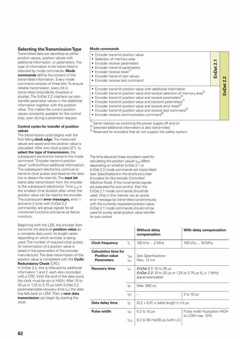
62
Selecting the Transmission TypeTransmitted data are identifi ed as either position values, position values with additional information, or parameters. The type of information to be transmitted is selected by mode commands. Mode
commands defi ne the content of the transmitted information. Every mode command consists of three bits. To ensure reliable transmission, every bit is transmitted redundantly (inverted or double). The EnDat 2.2 interface can also transfer parameter values in the additional information together with the position value. This makes the current position values constantly available for the control loop, even during a parameter request.
Control cycles for transfer of position
values
The transmission cycle begins with the fi rst falling clock edge. The measured values are saved and the position value is calculated. After two clock pulses (2T), to select the type of transmission, the subsequent electronics transmit the mode command “Encoder transmit position value” (with/without additional information).The subsequent electronics continue to transmit clock pulses and observe the data line to detect the start bit. The start bit starts data transmission from the encoder to the subsequent electronics. Time tcal is the smallest time duration after which the position value can be read by the encoder. The subsequent error messages, error 1 and error 2 (only with EnDat 2.2 commands), are group signals for all monitored functions and serve as failure monitors.
Beginning with the LSB, the encoder then transmits the absolute position value as a complete data word. Its length varies depending on which encoder is being used. The number of required clock pulses for transmission of a position value is saved in the parameters of the encoder manufacturer. The data transmission of the position value is completed with the Cyclic
Redundancy Check (CRC).In EnDat 2.2, this is followed by additional information 1 and 2, each also concluded with a CRC. With the end of the data word, the clock must be set to HIGH. After 10 to 30 µs or 1.25 to 3.75 µs (with EnDat 2.2 parameterizable recovery time tm) the data line falls back to LOW. Then a new data
transmission can begin by starting the clock.
Without delay
compensation
With delay compensation
Clock frequency fc 100 kHz ... 2 MHz 100 kHz ... 16 MHz
Calculation time for
Position value
Parameters
tcaltac
See Specifi cationsMax. 12 ms
Recovery time tm EnDat 2.1: 10 to 30 µsEnDat 2.2: 10 to 30 µs or 1.25 to 3.75 µs (fc ‡ 1 MHz) (parameterizable)
tR Max. 500 ns
tST – 2 to 10 µs
Data delay time tD (0.2 + 0.01 x cable length in m) µs
Pulse width tHI
tLO
0.2 to 10 µs
0.2 to 50 ms/30 µs (with LC)
Pulse width fl uctuation HIGH to LOW max. 10%
Mode commands
Encoder transmit position valueSelection of memory areaEncoder receive parametersEncoder transmit parametersEncoder receive reset1)
Encoder transmit test valuesEncoder receive test command
•••••••
En
Dat
2.1
En
Dat
2.2
Encoder transmit position value with additional informationEncoder transmit position value and receive selection of memory area2)
Encoder transmit position value and receive parameters2)
Encoder transmit position value and transmit parameters2)
Encoder transmit position value and receive error reset2)
Encoder transmit position value and receive test command2)
Encoder receive communication command3)
•••••••
1) Same reaction as switching the power supply off and on2) Selected additional information is also transmitted3) Reserved for encoders that do not support the safety system
The time absolute linear encoders need for calculating the position values tcal differs depending on whether EnDat 2.1 or EnDat 2.2 mode commands are transmitted (see Specifi cations in the brochure:Linear Encoders for Numerically Controlled Machine Tools). If the incremental signals are evaluated for axis control, then the EnDat 2.1 mode commands should be used. Only in this manner can an active error message be transmitted synchronously with the currently requested position value. EnDat 2.1 mode commands should not be used for purely serial position value transfer for axis control.
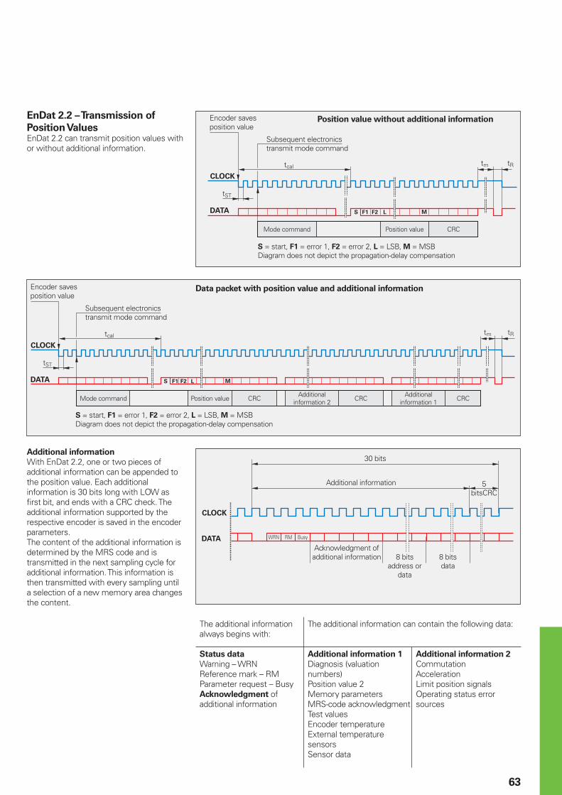
5%�"
�
5)
� � �
5� 5�
5%�" 5�
�
5)
5�
� � �
6789��:�;
63
Encoder saves position value
Subsequent electronics transmit mode command
Mode command Position value CRC
S = start, F1 = error 1, F2 = error 2, L = LSB, M = MSBDiagram does not depict the propagation-delay compensation
Position value without additional informationEnDat 2.2 – Transmission of
Position ValuesEnDat 2.2 can transmit position values with or without additional information.
Additional information
With EnDat 2.2, one or two pieces of additional information can be appended to the position value. Each additional information is 30 bits long with LOW as fi rst bit, and ends with a CRC check. The additional information supported by the respective encoder is saved in the encoder parameters.The content of the additional information is determined by the MRS code and is transmitted in the next sampling cycle for additional information. This information is then transmitted with every sampling until a selection of a new memory area changes the content.
The additional information always begins with:
The additional information can contain the following data:
Status data
Warning – WRNReference mark – RMParameter request – BusyAcknowledgment of additional information
Additional information 1
Diagnosis (valuation numbers)Position value 2Memory parametersMRS-code acknowledgmentTest valuesEncoder temperatureExternal temperature sensorsSensor data
Additional information 2
CommutationAccelerationLimit position signalsOperating status error sources
30 bits
Additional information 5 bitsCRC
Acknowledgment of additional information 8 bits
address or data
8 bitsdata
Encoder saves position value
Subsequent electronics transmit mode command
Mode command Position value CRCAdditional
information 2 CRCAdditional
information 1 CRC
S = start, F1 = error 1, F2 = error 2, L = LSB, M = MSBDiagram does not depict the propagation-delay compensation
Data packet with position value and additional information
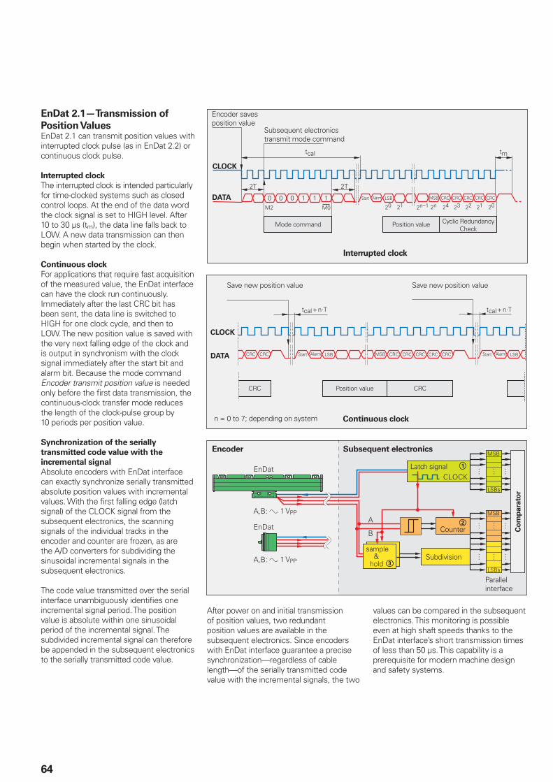
64
EnDat 2.1—Transmission of
Position ValuesEnDat 2.1 can transmit position values with interrupted clock pulse (as in EnDat 2.2) or continuous clock pulse.
Interrupted clock
The interrupted clock is intended particularly for time-clocked systems such as closed control loops. At the end of the data word the clock signal is set to HIGH level. After 10 to 30 µs (tm), the data line falls back to LOW. A new data transmission can then begin when started by the clock.
Continuous clock
For applications that require fast acquisition of the measured value, the EnDat interface can have the clock run continuously. Immediately after the last CRC bit has been sent, the data line is switched to HIGH for one clock cycle, and then to LOW. The new position value is saved with the very next falling edge of the clock and is output in synchronism with the clock signal immediately after the start bit and alarm bit. Because the mode command Encoder transmit position value is needed only before the fi rst data transmission, the continuous-clock transfer mode reduces the length of the clock-pulse group by 10 periods per position value.
Synchronization of the serially
transmitted code value with the
incremental signal
Absolute encoders with EnDat interface can exactly synchronize serially transmitted absolute position values with incremental values. With the fi rst falling edge (latch signal) of the CLOCK signal from the subsequent electronics, the scanning signals of the individual tracks in the encoder and counter are frozen, as are the A/D converters for subdividing the sinusoidal incremental signals in the subsequent electronics.
The code value transmitted over the serial interface unambiguously identifi es one incremental signal period. The position value is absolute within one sinusoidal period of the incremental signal. The subdivided incremental signal can therefore be appended in the subsequent electronics to the serially transmitted code value.
Encoder Subsequent electronics
Latch signal
Subdivision
Counter Co
mp
ara
tor
Parallel interface
1 VPP
1 VPP
After power on and initial transmission of position values, two redundant position values are available in the subsequent electronics. Since encoders with EnDat interface guarantee a precise synchronization—regardless of cable length—of the serially transmitted code value with the incremental signals, the two
Position value CRCCRC
Save new position value Save new position value
n = 0 to 7; depending on system Continuous clock
values can be compared in the subsequent electronics. This monitoring is possible even at high shaft speeds thanks to the EnDat interface’s short transmission times of less than 50 µs. This capability is a prerequisite for modern machine design and safety systems.
Encoder saves position value
Subsequent electronics transmit mode command
Mode command Position value Cyclic Redundancy Check
Interrupted clock
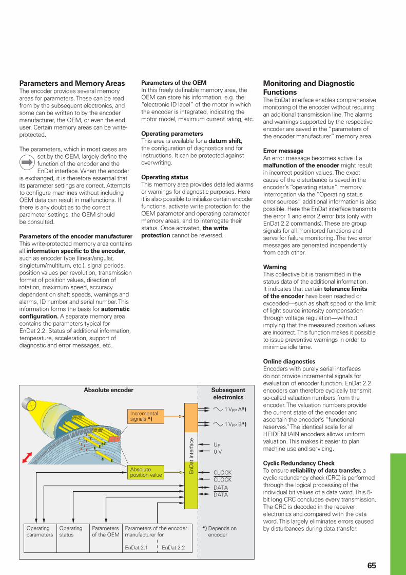
65
Parameters and Memory AreasThe encoder provides several memory areas for parameters. These can be read from by the subsequent electronics, and some can be written to by the encoder manufacturer, the OEM, or even the end user. Certain memory areas can be write-protected.
The parameters, which in most cases are set by the OEM, largely defi ne the function of the encoder and the EnDat interface. When the encoder
is exchanged, it is therefore essential that its parameter settings are correct. Attempts to confi gure machines without including OEM data can result in malfunctions. If there is any doubt as to the correct parameter settings, the OEM should be consulted.
Parameters of the encoder manufacturer
This write-protected memory area contains all information specifi c to the encoder, such as encoder type (linear/angular, singleturn/multiturn, etc.), signal periods, position values per revolution, transmission format of position values, direction of rotation, maximum speed, accuracy dependent on shaft speeds, warnings and alarms, ID number and serial number. This information forms the basis for automatic
confi guration. A separate memory area contains the parameters typical for EnDat 2.2: Status of additional information, temperature, acceleration, support of diagnostic and error messages, etc.
Absolute encoder Subsequent
electronics
Absolute position value
Operating parameters
Operating status
Parameters of the OEM
Parameters of the encoder manufacturer for
EnDat 2.1 EnDat 2.2
EnD
at in
terf
ace
Monitoring and Diagnostic
FunctionsThe EnDat interface enables comprehensive monitoring of the encoder without requiring an additional transmission line. The alarms and warnings supported by the respective encoder are saved in the “parameters of the encoder manufacturer” memory area.
Error message
An error message becomes active if a malfunction of the encoder might result in incorrect position values. The exact cause of the disturbance is saved in the encoder’s “operating status” memory.Interrogation via the “Operating status error sources” additional information is also possible. Here the EnDat interface transmits the error 1 and error 2 error bits (only with EnDat 2.2 commands). These are group signals for all monitored functions and serve for failure monitoring. The two error messages are generated independently from each other.
Warning
This collective bit is transmitted in the status data of the additional information. It indicates that certain tolerance limits
of the encoder have been reached or exceeded—such as shaft speed or the limit of light source intensity compensation through voltage regulation—without implying that the measured position values are incorrect. This function makes it possible to issue preventive warnings in order to minimize idle time.
Online diagnostics
Encoders with purely serial interfaces do not provide incremental signals for evaluation of encoder function. EnDat 2.2 encoders can therefore cyclically transmit so-called valuation numbers from the encoder. The valuation numbers provide the current state of the encoder and ascertain the encoder’s “functional reserves.” The identical scale for all HEIDENHAIN encoders allows uniform valuation. This makes it easier to plan machine use and servicing.
Cyclic Redundancy Check
To ensure reliability of data transfer, a cyclic redundancy check (CRC) is performed through the logical processing of the individual bit values of a data word. This 5-bit long CRC concludes every transmission. The CRC is decoded in the receiver electronics and compared with the data word. This largely eliminates errors caused by disturbances during data transfer.
Incremental signals *)
*) Depends on encoder
» 1 VPP A*)
» 1 VPP B*)
Parameters of the OEM
In this freely defi nable memory area, the OEM can store his information, e.g. the “electronic ID label” of the motor in which the encoder is integrated, indicating the motor model, maximum current rating, etc.
Operating parameters
This area is available for a datum shift, the confi guration of diagnostics and for instructions. It can be protected against overwriting.
Operating status
This memory area provides detailed alarms or warnings for diagnostic purposes. Here it is also possible to initialize certain encoder functions, activate write protection for the OEM parameter and operating parameter memory areas, and to interrogate their status. Once activated, the write
protection cannot be reversed.

�
�
�
�
�
�
� � � � �
�4
�� � �� � � �
����������
12
15
12
15
12 15
� �4
4 � � � � �
�4
12 �� � �� � � �
����������
15
12
15
4
66
Pin Layout
17-pin coupling or
fl ange socket M2312-pin PCB
connector
15-pin PCB
connector
Power supply Incremental signals1) Absolute position values
7 1 10 4 11 15 16 12 13 14 17 8 9
1b 6a 4b 3a / 2a 5b 4a 3b 6b 1a 2b 5a
13 11 14 12 / 1 2 3 4 7 8 9 10
UP Sensor2)
UP
0 V Sensor2)
0 VInternal
shield
A+ A– B+ B– DATA DATA CLOCK CLOCK
Brown/Green
Blue White/Green
White / Green/Black
Yellow/Black
Blue/Black
Red/Black
Gray Pink Violet Yellow
Other signals Cable shield connected to housing; UP = power supply voltage; T = temperatureSensor: The sensor line is connected internally with the corresponding power line.Vacant pins or wires must not be used!
1) Only with ordering designations 01 and 022) Not assigned if a power of 7 to 10 V is supplied via motor-internal adapter cable3) Only for motor-internal adapter cables4) For parallel supply lines5) Without separate connections for temperature sensor
5 6
/ /
/ /
T+3)
T–3)
Brown3) White3)
8-pin coupling or
M12 fl ange socket
4-pin PCB
connector
12-pin PCB
connector
15-pin PCB
connector
Power supply Absolute position values Other signals3)
2 8 1 5 3 4 7 6 / / / /
/ / / / / / / / 1a 1b / /
6a 1b 3a 4b 6b 1a 2b 6a / / / /
11 13 12 14 7 8 9 10 5 6 / /
UP4)
UP 0 V4)
0 V DATA DATA CLOCK CLOCK T+ T– T+5)
T–5)
Blue Brown/Green
White White/Green
Gray Pink Violet Yellow Brown Green Brown White
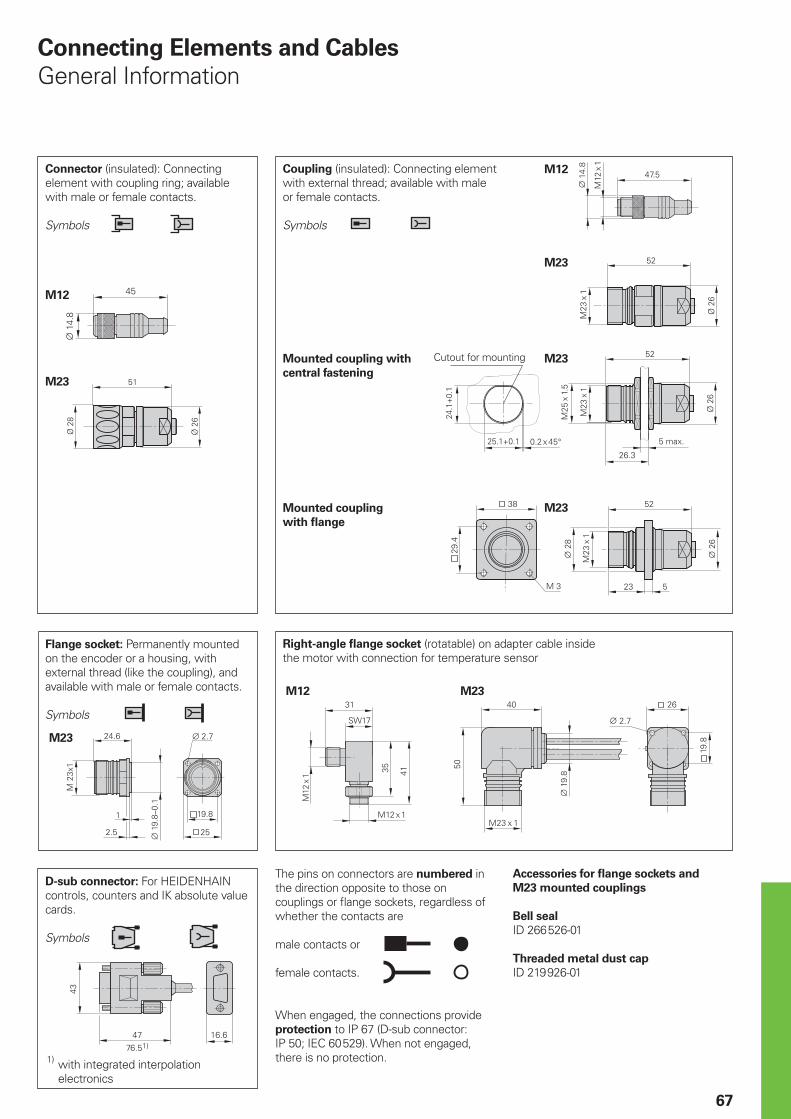
67
The pins on connectors are numbered in the direction opposite to those on couplings or fl ange sockets, regardless of whether the contacts are
male contacts or
female contacts.
When engaged, the connections provide protection to IP 67 (D-sub connector: IP 50; IEC 60 529). When not engaged, there is no protection.
Connecting Elements and Cables
General Information
Connector (insulated): Connecting element with coupling ring; available with male or female contacts.
Symbols
Coupling (insulated): Connecting element with external thread; available with male or female contacts.
Symbols
D-sub connector: For HEIDENHAIN controls, counters and IK absolute value cards.
Symbols
Accessories for fl ange sockets and
M23 mounted couplings
Bell seal
ID 266 526-01
Threaded metal dust cap
ID 219 926-01
M23
Flange socket: Permanently mounted on the encoder or a housing, with external thread (like the coupling), and available with male or female contacts.
Symbols
M23
M23
M23
M23
M23
Mounted coupling with
central fastening
Mounted coupling
with fl ange
Right-angle fl ange socket (rotatable) on adapter cable inside the motor with connection for temperature sensor
1) with integrated interpolation electronics
Cutout for mounting
M12
M12
M12
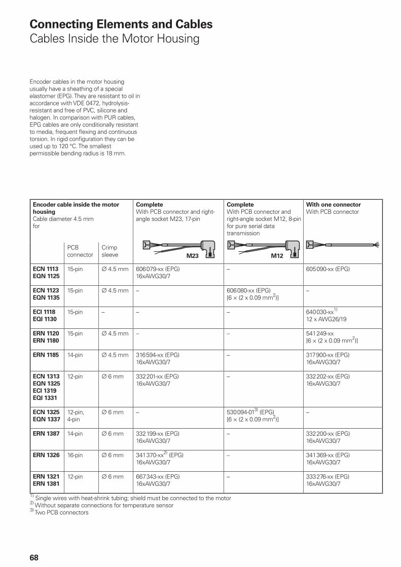
M23 M12
68
Connecting Elements and Cables
Cables Inside the Motor Housing
Encoder cable inside the motor
housing
Cable diameter 4.5 mmfor
Complete
With PCB connector and right-angle socket M23, 17-pin
Complete
With PCB connector and right-angle socket M12, 8-pin for pure serial data transmission
With one connector
With PCB connector
PCB connector
Crimp sleeve
ECN 1113
EQN 1125
15-pin ¬ 4.5 mm 606 079-xx (EPG)16xAWG30/7
– 605 090-xx (EPG)
ECN 1123
EQN 1135
15-pin ¬ 4.5 mm – 606 080-xx (EPG)[6 × (2 x 0.09 mm2)]
–
ECI 1118
EQI 1130
15-pin – – – 640 030-xx1)
12 x AWG26/19
ERN 1120
ERN 1180
15-pin ¬ 4.5 mm – – 541 249-xx[6 × (2 x 0.09 mm2)]
ERN 1185 14-pin ¬ 4.5 mm 316 594-xx (EPG)16xAWG30/7
– 317 900-xx (EPG)16xAWG30/7
ECN 1313
EQN 1325
ECI 1319
EQI 1331
12-pin ¬ 6 mm 332 201-xx (EPG)16xAWG30/7
– 332 202-xx (EPG)16xAWG30/7
ECN 1325
EQN 1337
12-pin,4-pin
¬ 6 mm – 530 094-013) (EPG)[6 × (2 x 0.09 mm2)]
–
ERN 1387 14-pin ¬ 6 mm 332 199-xx (EPG)16xAWG30/7
– 332 200-xx (EPG)16xAWG30/7
ERN 1326 16-pin ¬ 6 mm 341 370-xx2) (EPG)16xAWG30/7
– 341 369-xx (EPG)16xAWG30/7
ERN 1321
ERN 1381
12-pin ¬ 6 mm 667 343-xx (EPG)16xAWG30/7
– 333 276-xx (EPG)16xAWG30/7
1) Single wires with heat-shrink tubing; shield must be connected to the motor2) Without separate connections for temperature sensor3) Two PCB connectors
Encoder cables in the motor housing usually have a sheathing of a special elastomer (EPG). They are resistant to oil in accordance with VDE 0472, hydrolysis-resistant and free of PVC, silicone and halogen. In comparison with PUR cables, EPG cables are only conditionally resistant to media, frequent fl exing and continuous torsion. In rigid confi guration they can be used up to 120 °C. The smallest permissible bending radius is 18 mm.
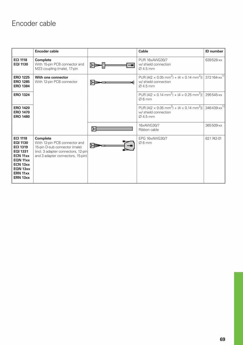
69
Encoder cable Cable ID number
ECI 1118
EQI 1130
Complete
With 15-pin PCB connector and M23 coupling (male), 17-pin
PUR 16xAWG30/7w/ shield connection¬ 4.5 mm
639 528-xx
ERO 1225
ERO 1285
ERO 1384
With one connector
With 12-pin PCB connectorPUR [4(2 × 0.05 mm2) + (4 × 0.14 mm2)]w/ shield connection¬ 4.5 mm
372 164-xx1)
ERO 1324 PUR [4(2 × 0.14 mm2) + (4 × 0.25 mm2)]¬ 6 mm
295 545-xx
ERO 1420
ERO 1470
ERO 1480
PUR [4(2 × 0.05 mm2) + (4 × 0.14 mm2)]w/ shield connection¬ 4.5 mm
346 439-xx1)
16xAWG30/7Ribbon cable
365 509-xx
ECI 1118
EQI 1130
ECI 1319
EQI 1331
ECN 11xx
EQN 11xx
ECN 13xx
EQN 13xx
ERN 11xx
ERN 13xx
Complete
With 12-pin PCB connector and 15-pin D-sub connector (male) (incl. 3 adapter connectors, 12-pin and 3 adapter connectors, 15-pin)
EPG 16xAWG30/7¬ 6 mm
621 742-01
Encoder cable
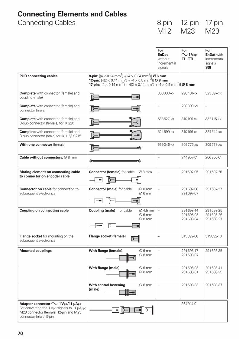
70
For
EnDat
without incremental signals
For
» 1 VPP
« TTL
For
EnDat with incremental signalsSSI
PUR connecting cables 8-pin: [(4 × 0.14 mm2) + (4 × 0.34 mm2)] ¬ 6 mm
12-pin: [4(2 × 0.14 mm2) + (4 × 0.5 mm2)] ¬ 8 mm
17-pin: [(4 × 0.14 mm2) + 4(2 × 0.14 mm2) + (4 × 0.5 mm2)] ¬ 8 mm
Complete with connector (female) and coupling (male)
368 330-xx 298 401-xx 323 897-xx
Complete with connector (female) and connector (male)
– 298 399-xx –
Complete with connector (female) and D-sub connector (female) for IK 220
533 627-xx 310 199-xx 332 115-xx
Complete with connector (female) and D-sub connector (male) for IK 115/IK 215
524 599-xx 310 196-xx 324 544-xx
With one connector (female) 559 346-xx 309 777-xx 309 778-xx
Cable without connectors, ¬ 8 mm – 244 957-01 266 306-01
Mating element on connecting cable
to connector on encoder cable
Connector (female) for cable ¬ 8 mm – 291 697-05 291 697-26
Connector on cable for connection to subsequent electronics
Connector (male) for cable ¬ 8 mm ¬ 6 mm
– 291 697-08291 697-07
291 697-27
Coupling on connecting cable Coupling (male) for cable ¬ 4.5 mm ¬ 6 mm ¬ 8 mm
– 291 698-14291 698-03291 698-04
291 698-25291 698-26291 698-27
Flange socket for mounting on the subsequent electronics
Flange socket (female) – 315 892-08 315 892-10
Mounted couplings
With fl ange (female) ¬ 6 mm ¬ 8 mm
– 291 698-17291 698-07
291 698-35
With fl ange (male) ¬ 6 mm ¬ 8 mm
– 291 698-08291 698-31
291 698-41291 698-29
With central fastening ¬ 6 mm(male)
– 291 698-33 291 698-37
Adapter connector » 1 VPP/11 µAPP
For converting the 1 VPP signals to 11 µAPP; M23 connector (female) 12-pin and M23 connector (male) 9-pin
– 364 914-01 –
Connecting Elements and Cables
Connecting Cables 8-pin 12-pin 17-pin M12 M23 M23
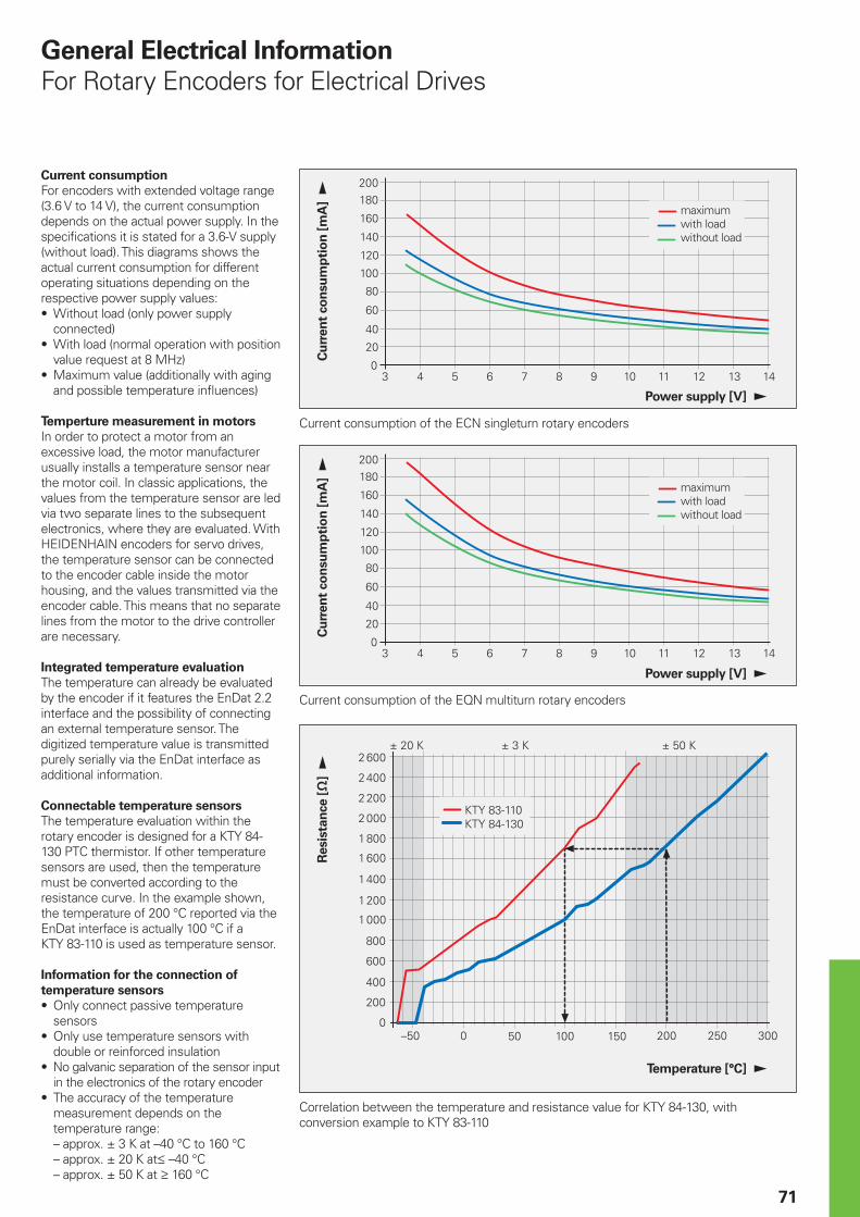
�
��
���
���
���
�����
����
�����
�����
�����
����
���
����
����
���� ��� ������������
< =���*���< =���*���
����<����< �����<
� ��
��
���
��
���
���
�����
��
��
�
� � � � �� �� � �� ��
� ��
��
���
��
���
���
�����
��
��
�
� � � � �� �� � �� ��
71
Current consumption
For encoders with extended voltage range (3.6 V to 14 V), the current consumption depends on the actual power supply. In the specifi cations it is stated for a 3.6-V supply (without load). This diagrams shows the actual current consumption for different operating situations depending on the respective power supply values:
Without load (only power supply connected)With load (normal operation with position value request at 8 MHz)Maximum value (additionally with aging and possible temperature infl uences)
Temperture measurement in motors
In order to protect a motor from an excessive load, the motor manufacturer usually installs a temperature sensor near the motor coil. In classic applications, the values from the temperature sensor are led via two separate lines to the subsequent electronics, where they are evaluated. With HEIDENHAIN encoders for servo drives, the temperature sensor can be connected to the encoder cable inside the motor housing, and the values transmitted via the encoder cable. This means that no separate lines from the motor to the drive controller are necessary.
Integrated temperature evaluation
The temperature can already be evaluated by the encoder if it features the EnDat 2.2 interface and the possibility of connecting an external temperature sensor. The digitized temperature value is transmitted purely serially via the EnDat interface as additional information.
Connectable temperature sensors
The temperature evaluation within the rotary encoder is designed for a KTY 84-130 PTC thermistor. If other temperature sensors are used, then the temperature must be converted according to the resistance curve. In the example shown, the temperature of 200 °C reported via the EnDat interface is actually 100 °C if a KTY 83-110 is used as temperature sensor.
Information for the connection of
temperature sensors
Only connect passive temperature sensorsOnly use temperature sensors with double or reinforced insulationNo galvanic separation of the sensor input in the electronics of the rotary encoderThe accuracy of the temperature measurement depends on the temperature range:– approx. ± 3 K at –40 °C to 160 °C– approx. ± 20 K at† –40 °C– approx. ± 50 K at ‡ 160 °C
•
•
•
•
•
•
•
General Electrical Information
For Rotary Encoders for Electrical Drives
Cu
rren
t co
nsu
mp
tio
n [
mA
]
Power supply [V]
Resis
tan
ce [−
]
Temperature [°C]
Correlation between the temperature and resistance value for KTY 84-130, with conversion example to KTY 83-110
Cu
rren
t co
nsu
mp
tio
n [
mA
]
Power supply [V]
Current consumption of the EQN multiturn rotary encoders
maximumwith loadwithout load
maximumwith loadwithout load
Current consumption of the ECN singleturn rotary encoders
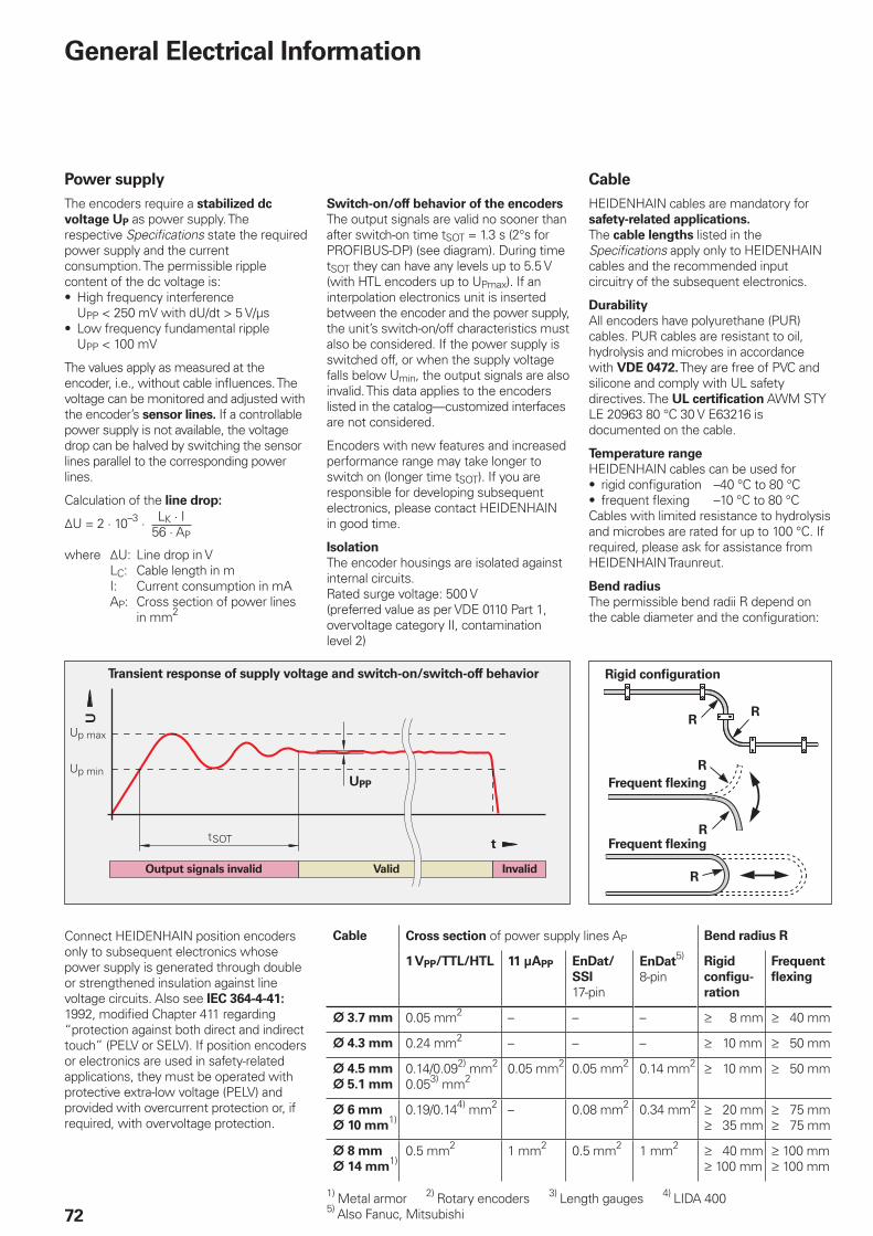
>?����
>?��&$
5�)�
�
72
General Electrical Information
Power supply
The encoders require a stabilized dc
voltage UP as power supply. The respective Specifi cations state the required power supply and the current consumption. The permissible ripple content of the dc voltage is:
High frequency interference UPP < 250 mV with dU/dt > 5 V/µsLow frequency fundamental ripple UPP < 100 mV
The values apply as measured at the encoder, i.e., without cable infl uences. The voltage can be monitored and adjusted with the encoder’s sensor lines. If a controllable power supply is not available, the voltage drop can be halved by switching the sensor lines parallel to the corresponding power lines.
Calculation of the line drop:
¹U = 2 · 10–3 ·
where ¹U: Line drop in V LC: Cable length in m I: Current consumption in mA AP: Cross section of power lines
in mm2
•
•
LK · I56 · AP
Rigid confi guration
Frequent fl exing
Frequent fl exing
Cable Cross section of power supply lines AP Bend radius R
1 VPP/TTL/HTL 11 µAPP EnDat/
SSI
17-pin
EnDat5)
8-pinRigid
confi gu-
ration
Frequent
fl exing
¬ 3.7 mm 0.05 mm2 – – – ‡ 8 mm ‡ 40 mm
¬ 4.3 mm 0.24 mm2 – – – ‡ 10 mm ‡ 50 mm
¬ 4.5 mm
¬ 5.1 mm
0.14/0.092) mm2
0.053) mm20.05 mm2 0.05 mm2 0.14 mm2 ‡ 10 mm ‡ 50 mm
¬ 6 mm
¬ 10 mm1)
0.19/0.144) mm2 – 0.08 mm2 0.34 mm2 ‡ 20 mm‡ 35 mm
‡ 75 mm‡ 75 mm
¬ 8 mm
¬ 14 mm1)
0.5 mm2 1 mm2 0.5 mm2 1 mm2 ‡ 40 mm‡ 100 mm
‡ 100 mm‡ 100 mm
1) Metal armor 2) Rotary encoders 3) Length gauges 4) LIDA 4005) Also Fanuc, Mitsubishi
Connect HEIDENHAIN position encoders only to subsequent electronics whose power supply is generated through double or strengthened insulation against line voltage circuits. Also see IEC 364-4-41: 1992, modifi ed Chapter 411 regarding “protection against both direct and indirect touch” (PELV or SELV). If position encoders or electronics are used in safety-related applications, they must be operated with protective extra-low voltage (PELV) and provided with overcurrent protection or, if required, with overvoltage protection.
Cable
HEIDENHAIN cables are mandatory for safety-related applications.
The cable lengths listed in the Specifi cations apply only to HEIDENHAIN cables and the recommended input circuitry of the subsequent electronics.
Durability
All encoders have polyurethane (PUR) cables. PUR cables are resistant to oil, hydrolysis and microbes in accordance with VDE 0472. They are free of PVC and silicone and comply with UL safety directives. The UL certifi cation AWM STYLE 20963 80 °C 30 V E63216 is documented on the cable.
Temperature range
HEIDENHAIN cables can be used forrigid confi guration –40 °C to 80 °Cfrequent fl exing –10 °C to 80 °C
Cables with limited resistance to hydrolysis and microbes are rated for up to 100 °C. If required, please ask for assistance from HEIDENHAIN Traunreut.
Bend radius
The permissible bend radii R depend on the cable diameter and the confi guration:
••
Transient response of supply voltage and switch-on/switch-off behavior
Switch-on/off behavior of the encoders
The output signals are valid no sooner than after switch-on time tSOT = 1.3 s (2°s for PROFIBUS-DP) (see diagram). During time tSOT they can have any levels up to 5.5 V (with HTL encoders up to UPmax). If an interpolation electronics unit is inserted between the encoder and the power supply, the unit’s switch-on/off characteristics must also be considered. If the power supply is switched off, or when the supply voltage falls below Umin, the output signals are also invalid. This data applies to the encoders listed in the catalog—customized interfaces are not considered.
Encoders with new features and increased performance range may take longer to switch on (longer time tSOT). If you are responsible for developing subsequent electronics, please contact HEIDENHAIN in good time.
Isolation
The encoder housings are isolated against internal circuits.Rated surge voltage: 500 V(preferred value as per VDE 0110 Part 1, overvoltage category II, contamination level 2)
Output signals invalid InvalidValid
UPP
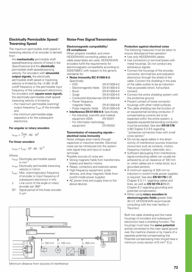
73
Minimum distance from sources of interference
Electrically Permissible Speed/
Traversing Speed
The maximum permissible shaft speed or traversing velocity of an encoder is derived from
the mechanically permissible shaft speed/traversing velocity (if listed in the Specifi cations) and the electrically permissible shaft speed/traversing velocity. For encoders with sinusoidal
output signals, the electrically permissible shaft speed or traversing velocity is limited by the –3 dB/ –6 dB cutoff frequency or the permissible input frequency of the subsequent electronics. For encoders with square-wave signals, the electrically permissible shaft speed/traversing velocity is limited by– the maximum permissible scanning/
output frequency fmax of the encoderand
– the minimum permissible edge separation a for the subsequent electronics.
For angular or rotary encoders
nmax = · 60 · 103
For linear encoders
vmax = fmax · SP · 60 · 10–3
Where: nmax: Electrically permissible speed
in min–1
vmax: Electrically permissible traversing velocity in m/min
fmax: Max. scanning/output frequency of encoder or input frequency of subsequent electronics in kHz
z: Line count of the angle or rotary encoder per 360°
SP: Signal period of the linear encoder in µm
fmaxz
Noise-Free Signal Transmission
Electromagnetic compatibility/
CE compliance
When properly installed, and when HEIDENHAIN connecting cables and cable assemblies are used, HEIDENHAIN encoders fulfi ll the requirements for electromagnetic compatibility according to 2004/108/EC with respect to the generic standards for:
Noise immunity IEC 61 000-6-2:
Specifi cally: – ESD EN 61 000-4-2 – Electromagnetic fi elds EN 61 000-4-3 – Burst EN 61 000-4-4 – Surge EN 61 000-4-5 – Conducted disturbances EN 61 000-4-6 – Power frequency
magnetic fi elds EN 61 000-4-8 – Pulse magnetic fi elds EN 61 000-4-9
Interference EN 61 000-6-4: Specifi cally: – For industrial, scientifi c and medical equipment (ISM) EN 55 011 – For information technology
equipment EN 55 022
Transmission of measuring signals—
electrical noise immunity
Noise voltages arise mainly through capacitive or inductive transfer. Electrical noise can be introduced into the system over signal lines and input or output terminals.Possible sources of noise are:
Strong magnetic fi elds from transformers, brakes and electric motorsRelays, contactors and solenoid valvesHigh-frequency equipment, pulse devices, and stray magnetic fi elds from switch-mode power suppliesAC power lines and supply lines to the above devices
•
•
•
••
•
Protection against electrical noise
The following measures must be taken to ensure disturbance-free operation:
Use only HEIDENHAIN cables.Use connectors or terminal boxes with metal housings. Do not conduct any extraneous signals.Connect the housings of the encoder, connector, terminal box and evaluation electronics through the shield of the cable. Connect the shielding in the area of the cable outlets to be as induction-free as possible (short, full-surface contact).Connect the entire shielding system with the protective ground.Prevent contact of loose connector housings with other metal surfaces.The cable shielding has the function of an equipotential bonding conductor. If compensating currents are to be expected within the entire system, a separate equipotential bonding conductor must be provided. See also EN 50 178/ 4.98 Chapter 5.2.9.5 regarding “protective connection lines with small cross section.”Do not lay signal cables in the direct vicinity of interference sources (inductive consumers such as contacts, motors, frequency inverters, solenoids, etc.).Suffi cient decoupling from interference-signal-conducting cables can usually be achieved by an air clearance of 100 mm or, when cables are in metal ducts, by a grounded partition.A minimum spacing of 200 mm to inductors in switch-mode power supplies is required. See also EN 50 178/4.98 Chapter 5.3.1.1, regarding cables and lines, as well as EN 50 174-2/09.01, Chapter 6.7, regarding grounding and potential compensation.When using rotary encoders in
electromagnetic fi elds greater than 30 mT, HEIDENHAIN recommends consulting with the main facility in Traunreut.
Both the cable shielding and the metal housings of encoders and subsequent electronics have a shielding function. The housings must have the same potential and be connected to the main signal ground over the machine chassis or by means of a separate potential compensating line. Potential compensating lines should have a minimum cross section of 6 mm2 (Cu).
••
•
•
•
•
•
•
•
•
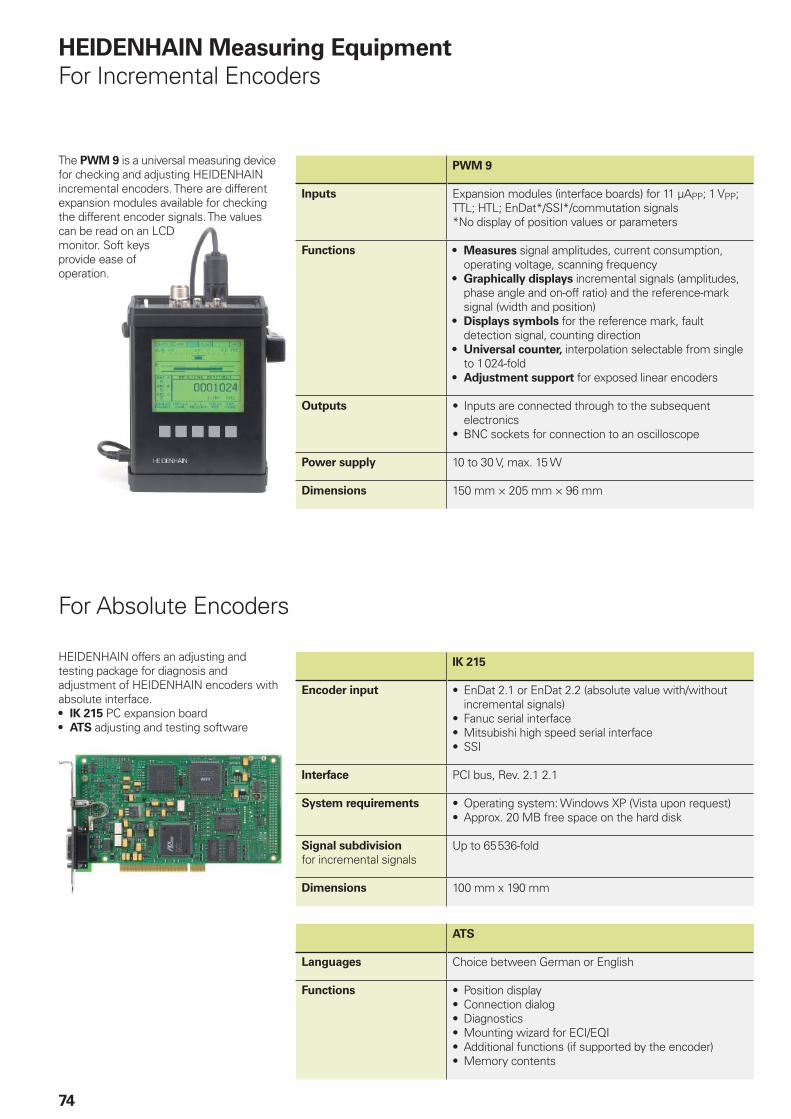
74
The PWM 9 is a universal measuring device for checking and adjusting HEIDENHAIN incremental encoders. There are different expansion modules available for checking the different encoder signals. The values can be read on an LCD monitor. Soft keys provide ease of operation.
PWM 9
Inputs Expansion modules (interface boards) for 11 µAPP; 1 VPP; TTL; HTL; EnDat*/SSI*/commutation signals*No display of position values or parameters
Functions Measures signal amplitudes, current consumption, operating voltage, scanning frequencyGraphically displays incremental signals (amplitudes, phase angle and on-off ratio) and the reference-mark signal (width and position)Displays symbols for the reference mark, fault detection signal, counting directionUniversal counter, interpolation selectable from single to 1 024-foldAdjustment support for exposed linear encoders
•
•
•
•
•
Outputs Inputs are connected through to the subsequent electronicsBNC sockets for connection to an oscilloscope
•
•
Power supply 10 to 30 V, max. 15 W
Dimensions 150 mm × 205 mm × 96 mm
For Absolute Encoders
HEIDENHAIN Measuring Equipment
For Incremental Encoders
HEIDENHAIN offers an adjusting and testing package for diagnosis and adjustment of HEIDENHAIN encoders with absolute interface.
IK 215 PC expansion boardATS adjusting and testing software
•
•
IK 215
Encoder input EnDat 2.1 or EnDat 2.2 (absolute value with/without incremental signals)Fanuc serial interfaceMitsubishi high speed serial interfaceSSI
•
•••
Interface PCI bus, Rev. 2.1 2.1
System requirements Operating system: Windows XP (Vista upon request)Approx. 20 MB free space on the hard disk
••
Signal subdivision
for incremental signalsUp to 65 536-fold
Dimensions 100 mm x 190 mm
ATS
Languages Choice between German or English
Functions Position displayConnection dialogDiagnosticsMounting wizard for ECI/EQIAdditional functions (if supported by the encoder)Memory contents
••••••
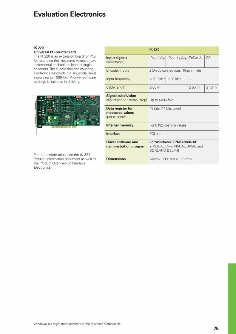
75
Windows is a registered trademark of the Microsoft Corporation.
Evaluation Electronics
IK 220
Universal PC counter card
The IK 220 is an expansion board for PCs for recording the measured values of two incremental or absolute linear or angle encoders. The subdivision and counting electronics subdivide the sinusoidal input signals up to 4 096-fold. A driver software package is included in delivery.
For more information, see the IK 220 Product Information document as well as the Product Overview of Interface Electronics.
IK 220
Input signals
(switchable)» 1 VPP » 11 µAPP EnDat 2.1 SSI
Encoder inputs 2 D-sub connections (15-pin) male
Input frequency † 500 kHz † 33 kHz –
Cable length † 60 m † 50 m † 10 m
Signal subdivision
(signal period : meas. step) Up to 4 096-fold
Data register for
measured values (per channel)
48 bits (44 bits used)
Internal memory For 8 192 position values
Interface PCI bus
Driver software and
demonstration program
For Windows 98/NT/2000/XP
in VISUAL C++, VISUAL BASIC and BORLAND DELPHI
Dimensions Approx. 190 mm × 100 mm
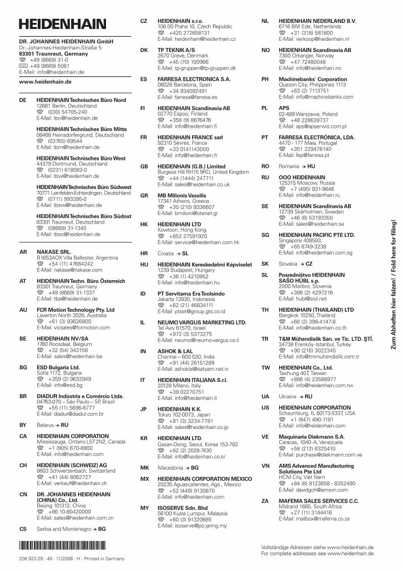
NL HEIDENHAIN NEDERLAND B.V. 6716 BM Ede, Netherlands { +31 (318) 581800 E-Mail: [email protected]
NO HEIDENHAIN Scandinavia AB 7300 Orkanger, Norway { +47 72480048 E-Mail: [email protected]
PH Machinebanks` Corporation Quezon City, Philippines 1113 { +63 (2) 7113751 E-Mail: [email protected]
PL APS 02-489 Warszawa, Poland { +48 228639737 E-Mail: [email protected]
PT FARRESA ELECTRÓNICA, LDA. 4470 - 177 Maia, Portugal { +351 229478140 E-Mail: [email protected]
RO Romania − HU
RU OOO HEIDENHAIN 125315 Moscow, Russia { +7 (495) 931-9646 E-Mail: [email protected]
SE HEIDENHAIN Scandinavia AB 12739 Skärholmen, Sweden { +46 (8) 53193350 E-Mail: [email protected]
SG HEIDENHAIN PACIFIC PTE LTD. Singapore 408593, { +65 6749-3238 E-Mail: [email protected]
SK Slovakia − CZ
SL Posredništvo HEIDENHAIN SAŠO HÜBL s.p. 2000 Maribor, Slovenia { +386 (2) 4297216 E-Mail: [email protected]
TH HEIDENHAIN (THAILAND) LTD Bangkok 10250, Thailand { +66 (2) 398-4147-8 E-Mail: [email protected]
TR T&M Mühendislik San. ve Tic. LTD. ŞTİ. 34738 Erenköy-Istanbul, Turkey { +90 (216) 3022345 E-Mail: [email protected]
TW HEIDENHAIN Co., Ltd. Taichung 407, Taiwan { +886 (4) 23588977 E-Mail: [email protected]
UA Ukraine − RU
US HEIDENHAIN CORPORATION Schaumburg, IL 60173-5337, USA { +1 (847) 490-1191 E-Mail: [email protected]
VE Maquinaria Diekmann S.A. Caracas, 1040-A, Venezuela { +58 (212) 6325410 E-Mail: [email protected]
VN AMS Advanced Manufacturing Solutions Pte Ltd HCM City, Viêt Nam { +84 (8) 9123658 - 8352490 E-Mail: [email protected]
ZA MAFEMA SALES SERVICES C.C. Midrand 1685, South Africa { +27 (11) 3144416 E-Mail: [email protected]
CZ HEIDENHAIN s.r.o. 106 00 Praha 10, Czech Republic { +420 272658131 E-Mail: [email protected]
DK TP TEKNIK A/S 2670 Greve, Denmark { +45 (70) 100966 E-Mail: [email protected]
ES FARRESA ELECTRONICA S.A. 08028 Barcelona, Spain { +34 934092491 E-Mail: [email protected]
FI HEIDENHAIN Scandinavia AB 02770 Espoo, Finland { +358 (9) 8676476 E-Mail: [email protected]
FR HEIDENHAIN FRANCE sarl 92310 Sèvres, France { +33 0141143000 E-Mail: [email protected]
GB HEIDENHAIN (G.B.) Limited Burgess Hill RH15 9RD, United Kingdom { +44 (1444) 247711 E-Mail: [email protected]
GR MB Milionis Vassilis 17341 Athens, Greece { +30 (210) 9336607 E-Mail: [email protected]
HK HEIDENHAIN LTD Kowloon, Hong Kong { +852 27591920 E-Mail: [email protected]
HR Croatia − SL
HU HEIDENHAIN Kereskedelmi Képviselet 1239 Budapest, Hungary { +36 (1) 4210952 E-Mail: [email protected]
ID PT Servitama Era Toolsindo Jakarta 13930, Indonesia { +62 (21) 46834111 E-Mail: [email protected]
IL NEUMO VARGUS MARKETING LTD. Tel Aviv 61570, Israel { +972 (3) 5373275 E-Mail: [email protected]
IN ASHOK & LAL Chennai – 600 030, India { +91 (44) 26151289 E-Mail: [email protected]
IT HEIDENHAIN ITALIANA S.r.l. 20128 Milano, Italy { +39 02270751 E-Mail: [email protected]
JP HEIDENHAIN K.K. Tokyo 102-0073, Japan { +81 (3) 3234-7781 E-Mail: [email protected]
KR HEIDENHAIN LTD. Gasan-Dong, Seoul, Korea 153-782 { +82 (2) 2028-7430 E-Mail: [email protected]
MK Macedonia − BG
MX HEIDENHAIN CORPORATION MEXICO 20235 Aguascalientes, Ags., Mexico { +52 (449) 9130870 E-Mail: [email protected]
MY ISOSERVE Sdn. Bhd 56100 Kuala Lumpur, Malaysia { +60 (3) 91320685 E-Mail: [email protected]
AR NAKASE SRL. B1653AOX Villa Ballester, Argentina { +54 (11) 47684242 E-Mail: [email protected]
AT HEIDENHAIN Techn. Büro Österreich 83301 Traunreut, Germany { +49 (8669) 31-1337 E-Mail: [email protected]
AU FCR Motion Technology Pty. Ltd Laverton North 3026, Australia { +61 (3) 93626800 E-Mail: [email protected]
BE HEIDENHAIN NV/SA 1760 Roosdaal, Belgium { +32 (54) 343158 E-Mail: [email protected]
BG ESD Bulgaria Ltd. Sofi a 1172, Bulgaria { +359 (2) 9632949 E-Mail: [email protected]
BR DIADUR Indústria e Comércio Ltda. 04763-070 – São Paulo – SP, Brazil { +55 (11) 5696-6777 E-Mail: [email protected]
BY Belarus − RU
CA HEIDENHAIN CORPORATION Mississauga, Ontario L5T2N2, Canada { +1 (905) 670-8900 E-Mail: [email protected]
CH HEIDENHAIN (SCHWEIZ) AG 8603 Schwerzenbach, Switzerland { +41 (44) 8062727 E-Mail: [email protected]
CN DR. JOHANNES HEIDENHAIN (CHINA) Co., Ltd. Beijing 101312, China { +86 10-80420000 E-Mail: [email protected]
CS Serbia and Montenegro − BG
DE HEIDENHAIN Technisches Büro Nord 12681 Berlin, Deutschland { (030) 54705-240 E-Mail: [email protected]
HEIDENHAIN Technisches Büro Mitte 08468 Heinsdorfergrund, Deutschland { (03765) 69544 E-Mail: [email protected]
HEIDENHAIN Technisches Büro West 44379 Dortmund, Deutschland { (0231) 618083-0 E-Mail: [email protected]
HEIDENHAIN Technisches Büro Südwest 70771 Leinfelden-Echterdingen, Deutschland { (0711) 993395-0 E-Mail: [email protected]
HEIDENHAIN Technisches Büro Südost 83301 Traunreut, Deutschland { (08669) 31-1345 E-Mail: [email protected]
Vollständige Adressen siehe www.heidenhain.deFor complete addresses see www.heidenhain.de
������������ ��� ��������������� ��������������������������������������� ���������������� ����������������� �!"��#�$����������
������ !���� ��!�
208 922-29 · 40 · 11/2008 · H · Printed in Germany
Zu
m A
bh
eft
en
hie
r fa
lzen
! /
Fo
ld h
ere
fo
r fi
lin
g!


![Servo DEU ENG 04 09 999015 Web - Chain & Drives · 1B = mean input speed during braking [min-1]n 1B = mittlere Antriebsdrehzahl beim Bremsen [min-1] n 1m = mean input speed during](https://img.pdfslide.org/doc/110x75/5ed363008217c4316e30a64b/servo-deu-eng-04-09-999015-web-chain-drives-1b-mean-input-speed-during.jpg)