Embed Size (px)
Citation preview
Diese Zulassung umfasst
This Approval contains
37 Seiten einschließlich 27 Anhänge 37 pages including 27 annexes
Diese Zulassung ersetzt This Approval replaces
ETA-12/0258 mit Geltungsdauer vom 08.08.2012 bis 08.08.2017 ETA-12/0258 with validity from 08.08.2012 to 08.08.2017
E u r o p ä i s c h e O r g a n i s a t i o n f ü r T e c h n i s c h e Z u l a s s u n g e n
E u r o p e a n O r g a n i s a t i o n f o r T e c h n i c a l A p p r o v a l s
Z36351.13 8.06.01-237/13
English translation prepared by DIBt - Original version in German language
Handelsbezeichnung Trade name
fischer Superbond
fischer Superbond
Zulassungsinhaber
Holder of approval fischerwerke GmbH & Co. KG Otto-Hahn-Straße 15 79211 Denzlingen DEUTSCHLAND
Zulassungsgegenstand und Verwendungszweck
Verbundanker in den Größen M8 bis M30 zur Verankerung im Beton
Generic type and use of construction product
Bonded Anchor of sizes M8 to M30 for use in concrete
Geltungsdauer:
Validity: vom from
26 June 2013
bis to
8 August 2017
Herstellwerk
Manufacturing plant fischerwerke
European Technical Approval ETA-12/0258
Ele
ctro
nic
copy
of t
he E
TA b
y D
IBt:
ETA
-12/
0258
European technical approval ETA-12/0258 English translation prepared by DIBt
Page 2 of 37 | 26 June 2013
Z36351.13 8.06.01-237/13
I LEGAL BASES AND GENERAL CONDITIONS
1 This European technical approval is issued by Deutsches Institut für Bautechnik in accordance with:
Council Directive 89/106/EEC of 21 December 1988 on the approximation of laws, regulations and administrative provisions of Member States relating to construction products1, modified by Council Directive 93/68/EEC2 and Regulation (EC) N° 1882/2003 of the European Parliament and of the Council3;
Gesetz über das In-Verkehr-Bringen von und den freien Warenverkehr mit Bauprodukten zur Umsetzung der Richtlinie 89/106/EWG des Rates vom 21. Dezember 1988 zur Angleichung der Rechts- und Verwaltungsvorschriften der Mitgliedstaaten über Bauprodukte und anderer Rechtsakte der Europäischen Gemeinschaften (Bauproduktengesetz - BauPG) vom 28. April 19984, as amended by Article 2 of the law of 8 November 20115;
Common Procedural Rules for Requesting, Preparing and the Granting of European technical approvals set out in the Annex to Commission Decision 94/23/EC6;
Guideline for European technical approval of "Metal anchors for use in concrete - Part 5: Bonded anchors", ETAG 001-05.
2 Deutsches Institut für Bautechnik is authorized to check whether the provisions of this European technical approval are met. Checking may take place in the manufacturing plant. Nevertheless, the responsibility for the conformity of the products to the European technical approval and for their fitness for the intended use remains with the holder of the European technical approval.
3 This European technical approval is not to be transferred to manufacturers or agents of manufacturers other than those indicated on page 1, or manufacturing plants other than those indicated on page 1 of this European technical approval.
4 This European technical approval may be withdrawn by Deutsches Institut für Bautechnik, in particular pursuant to information by the Commission according to Article 5(1) of Council Directive 89/106/EEC.
5 Reproduction of this European technical approval including transmission by electronic means shall be in full. However, partial reproduction can be made with the written consent of Deutsches Institut für Bautechnik. In this case partial reproduction has to be designated as such. Texts and drawings of advertising brochures shall not contradict or misuse the European technical approval.
6 The European technical approval is issued by the approval body in its official language. This version corresponds fully to the version circulated within EOTA. Translations into other languages have to be designated as such.
1 Official Journal of the European Communities L 40, 11 February 1989, p. 12
2 Official Journal of the European Communities L 220, 30 August 1993, p. 1
3 Official Journal of the European Union L 284, 31 October 2003, p. 25
4 Bundesgesetzblatt Teil I 1998, p. 812
5 Bundesgesetzblatt Teil I 2011, p. 2178
6 Official Journal of the European Communities L 17, 20 January 1994, p. 34
Ele
ctro
nic
copy
of t
he E
TA b
y D
IBt:
ETA
-12/
0258
European technical approval ETA-12/0258 English translation prepared by DIBt
Page 3 of 37 | 26 June 2013
Z36351.13 8.06.01-237/13
II SPECIFIC CONDITIONS OF THE EUROPEAN TECHNICAL APPROVAL
1 Definition of product and intended use
1.1 Definition of the construction product
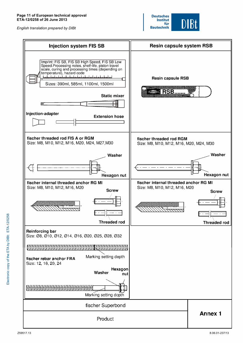
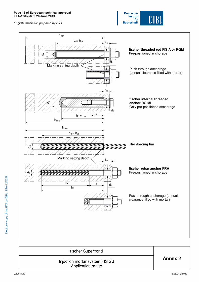
The fischer Superbond is a bonded anchor consisting of a cartridge with injection mortar FIS SB, FIS SB Low Speed or FIS SB High Speed or a mortar capsule fischer RSB and a steel element. The steel elements are either
- fischer anchor rods FIS A in the range of M8 to M30 or
- fischer threaded rod RGM in the range of M8 to M30 or
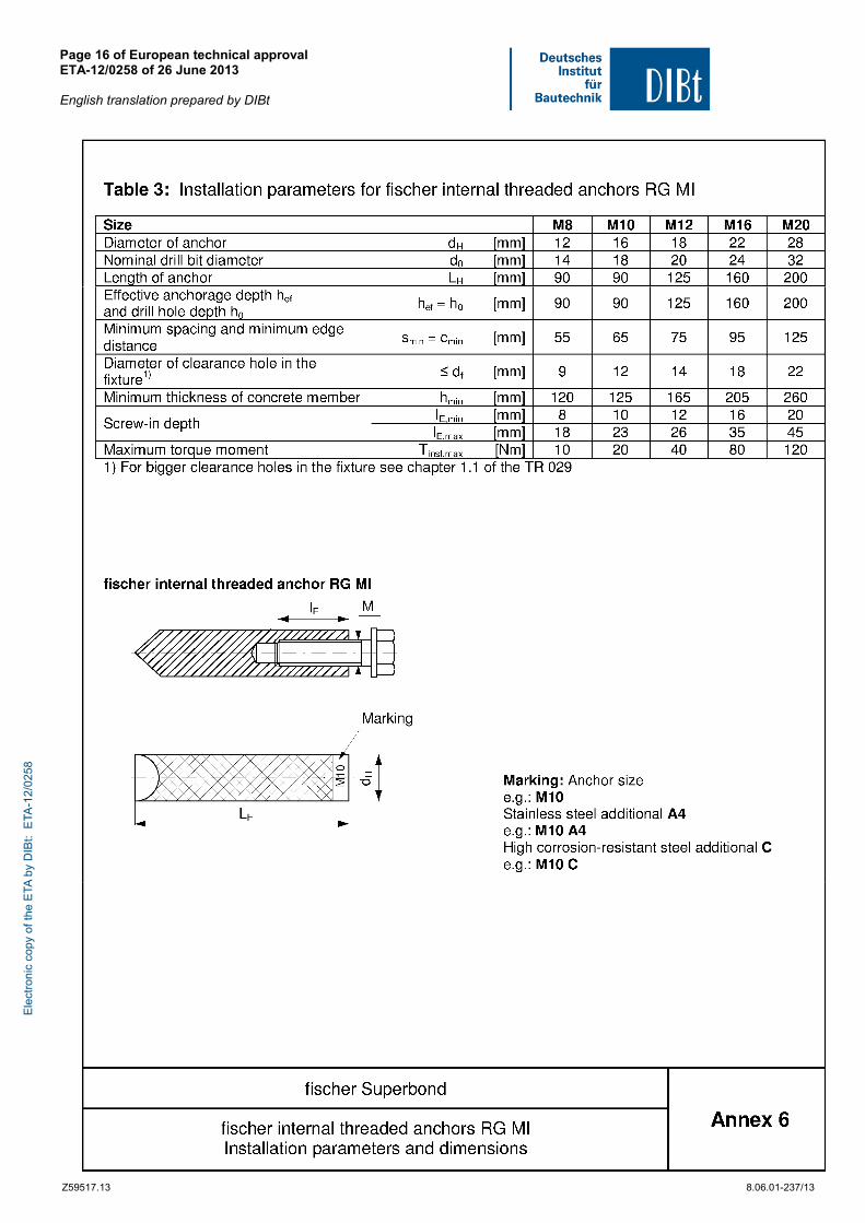
- fischer internal threaded anchor RG MI in the range of M8 to M20 or
- Reinforcing bar in the range of Ø 8 to Ø 32 or
- fischer rebar anchor FRA in the range of 12 to 24. In case of the injection system the anchor rod is placed into a drilled hole filled with injection mortar.
The mortar capsule is placed in the hole and the threaded rod or the internal threaded anchor is driven by machine with simultaneous hammering and turning.
The steel elements are anchored via the bond between steel element, injection mortar and concrete.
An illustration of the product and intended use is given in Annexes 1 to 4.
1.2 Intended use
The anchor is intended to be used for anchorages for which requirements for mechanical resistance and stability and safety in use in the sense of the Essential Requirements 1 and 4 of Council Directive 89/106 EEC shall be fulfilled and failure of anchorages made with these products would cause risk to human life and/or lead to considerable economic consequences. Safety in case of fire (Essential Requirement 2) is not covered in this European technical approval. The anchor is to be used only for anchorages subject to static or quasi-static loading in reinforced or unreinforced normal weight concrete of strength classes C20/25 at minimum and C50/60 at most according to EN 206:2000-12.
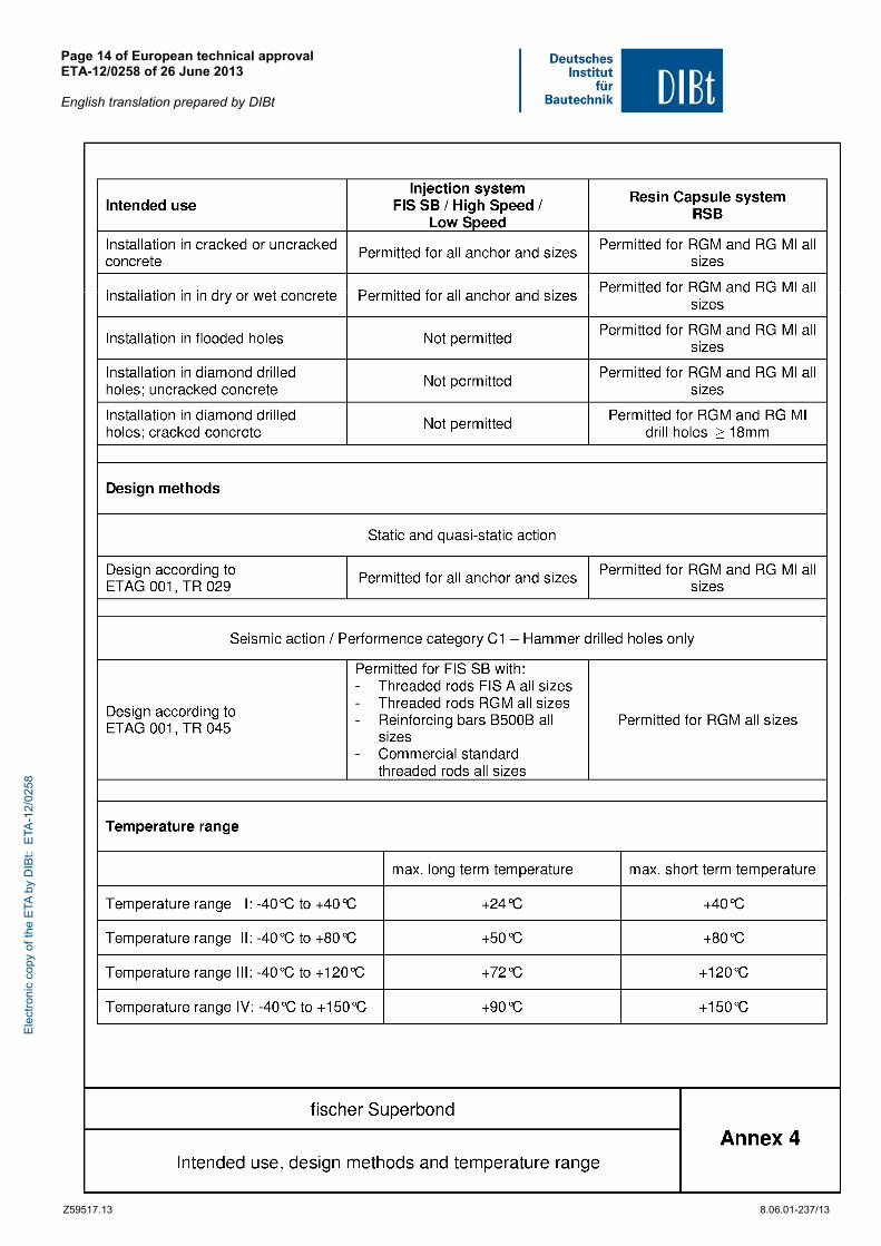
The anchor may be installed in cracked or non-cracked concrete.
The capsule system may be used in dry or wet concrete or in flooded holes excepting sea water. The injection system may be used in dry or wet concrete; it must not be installed in flooded holes.
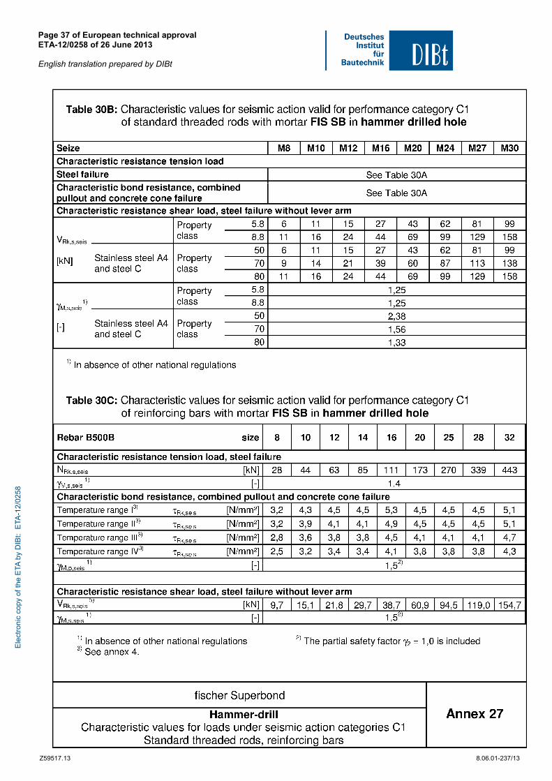
The anchor with steel elements given in Annex 4 may also be used under seismic action for performance category C1 according to Annexes 25 to 27.
The anchor may be used in the following temperature ranges:
Temperature range I: -40 °C to +40 °C (max short term temperature +40 °C and max long term temperature +24 °C)
Temperature range II: -40 °C to +80 °C (max short term temperature +80 °C and max long term temperature +50 °C)
Temperature range III: -40 °C to +120 °C (max short term temperature +120 °C and max long term temperature +72 °C)
Ele
ctro
nic
copy
of t
he E
TA b
y D
IBt:
ETA
-12/
0258
European technical approval ETA-12/0258 English translation prepared by DIBt
Page 4 of 37 | 26 June 2013
Z36351.13 8.06.01-237/13
Temperature range IV: -40 °C to +150 °C (max short term temperature +150 °C and max long term temperature +90 °C)
Elements made of zinc plated or hot-dip galvanised steel:
The steel elements made of zinc plated or hot-dip galvanised steel may only be used in structures subject to dry internal conditions.
Elements made of stainless steel A4:
The steel elements made of stainless steel may be used in structures subject to dry internal conditions and also in structures subject to external atmospheric exposure (including industrial and marine environment), or exposure in permanently damp internal conditions, if no particular aggressive conditions exist. Such particular aggressive conditions are e. g. permanent, alternating immersion in seawater or the splash zone of seawater, chloride atmosphere of indoor swimming pools or atmosphere with extreme chemical pollution (e. g. in desulphurization plants or road tunnels where de-icing materials are used).
Elements made of high corrosion resistant steel C:
The steel elements made of high corrosion resistant steel may be used in structures subject to dry internal conditions and also in structures subject to external atmospheric exposure, in permanently damp internal conditions or in other particular aggressive conditions. Such particular aggressive conditions are e. g. permanent, alternating immersion in seawater or the splash zone of seawater, chloride atmosphere of indoor swimming pools or atmosphere with chemical pollution (e. g. in desulphurization plants or road tunnels where de-icing materials are used).
Elements made of reinforcing bars:
Post-installed reinforcing bars may be used as anchor designed in accordance with the EOTA Technical Reports TR 029 and TR 045 only. Such applications are e.g. concrete overlay or shear dowel connections or the connections of a wall predominantly loaded by shear and compression forces with the foundation, where the reinforcing bars act as dowels to take up shear forces. Connections with post-installed reinforcing bars in concrete structures designed in accordance with EN1992-1-1: 2004 are not covered by this European technical approval.
The provisions made in this European technical approval are based on an assumed working life of the anchor of 50 years. The indications given on the working life cannot be interpreted as a guarantee given by the producer, but are to be regarded only as a means for choosing the right products in relation to the expected economically reasonable working life of the works.
2 Characteristics of product and methods of verification
2.1 Characteristics of product
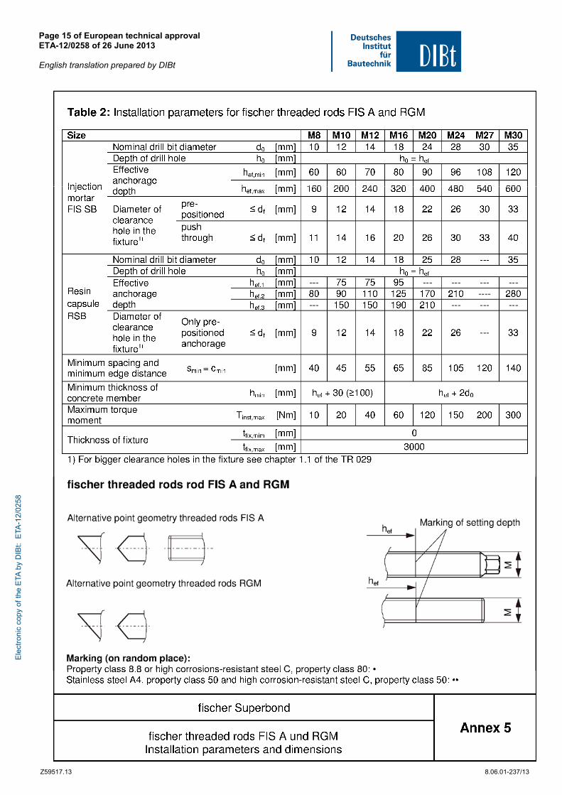
The anchor corresponds to the drawings and provisions given in the Annexes. The values, dimensions and tolerances of the anchor not indicated in the Annexes shall correspond to the respective values laid down in the technical documentation7 of this European technical approval.
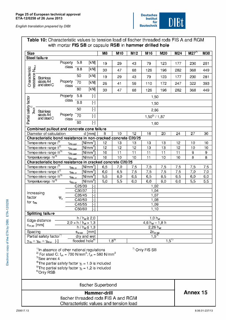
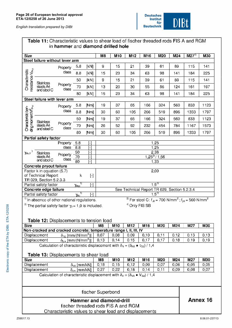
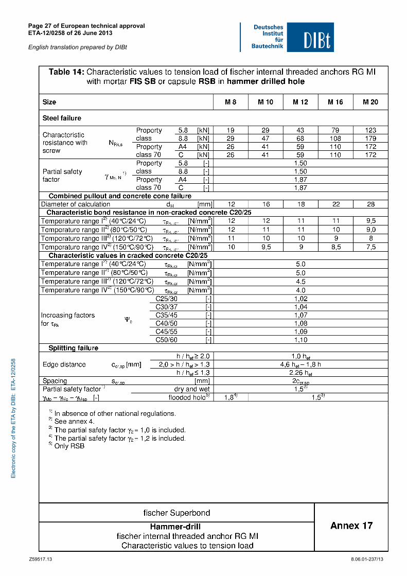
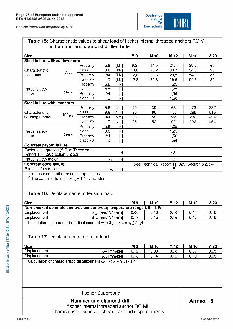
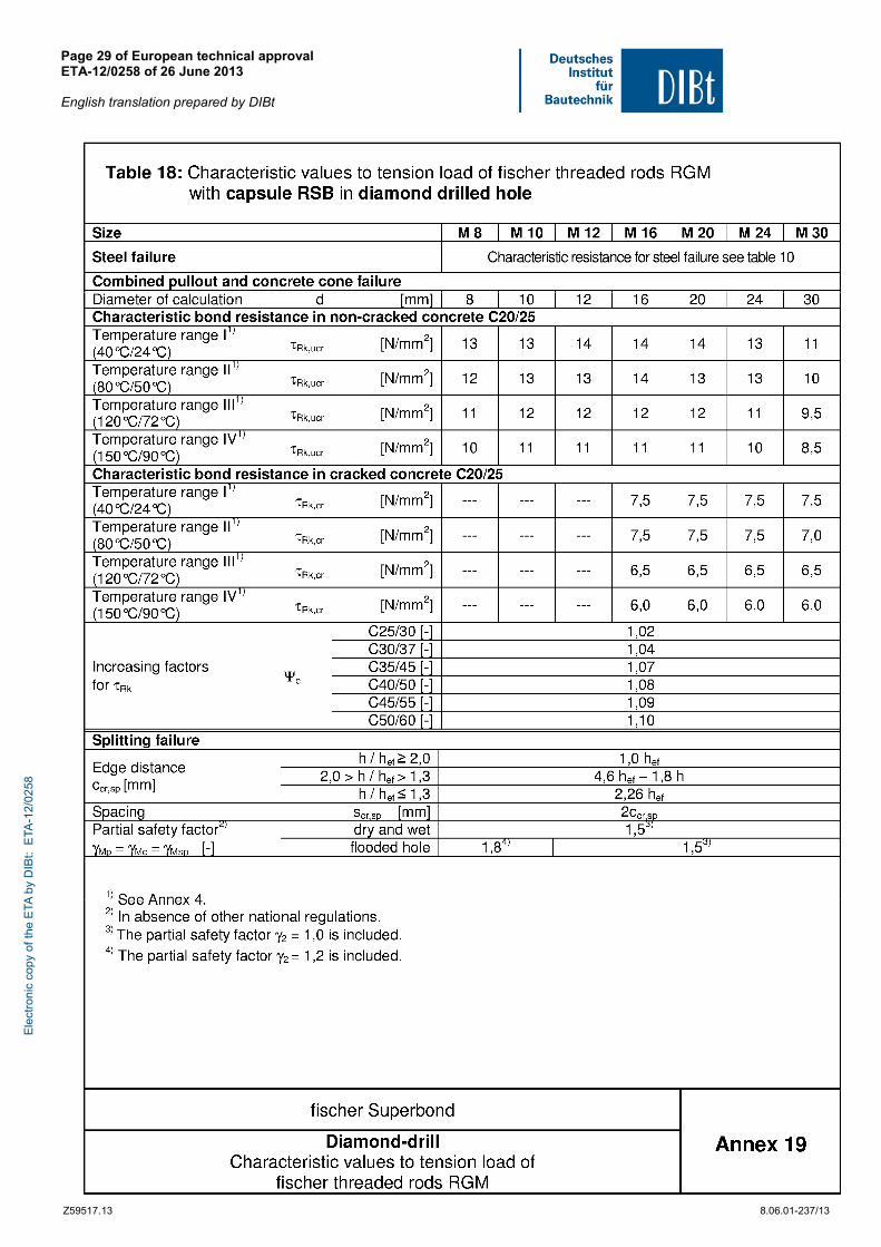
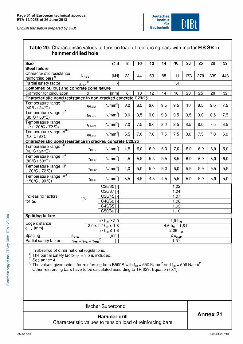
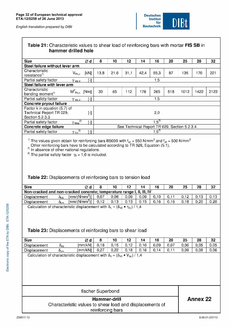
The characteristic anchor values for the design of anchorages are given in the Annexes.
The two components of the injection mortar fischer FIS SB, FIS SB High Speed and SB Low Speed are delivered in unmixed condition in side-by side-cartridges of sizes 390 ml, 585 ml, 1100 ml or 1500 ml or in resin capsules RSB according to Annex 1.
7 The technical documentation of this European technical approval is deposited at the Deutsches Institut für Bautechnik
and, as far as relevant for the tasks of the approved bodies involved in the attestation of conformity procedure, is handed over to the approved bodies.
Ele
ctro
nic
copy
of t
he E
TA b
y D
IBt:
ETA
-12/
0258
European technical approval ETA-12/0258 English translation prepared by DIBt
Page 5 of 37 | 26 June 2013
Z36351.13 8.06.01-237/13
Each mortar cartridge and each mortar capsule RSB and each steel element is marked in accordance with the Annexes.
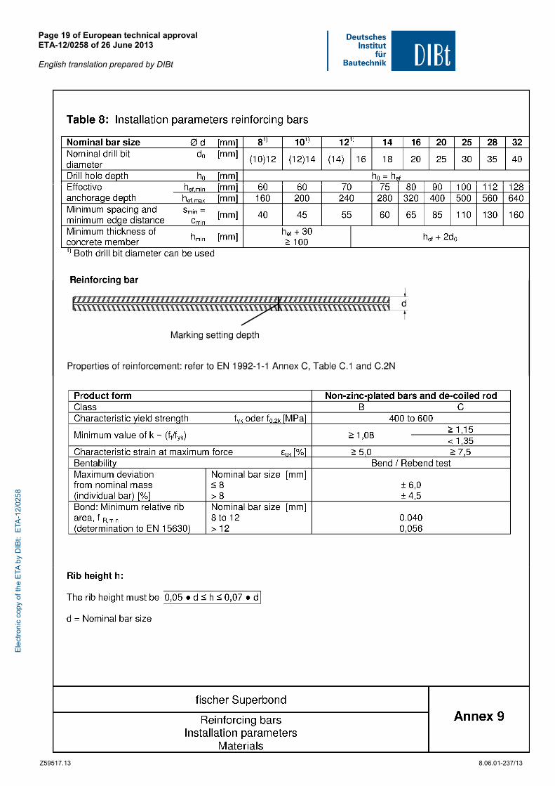
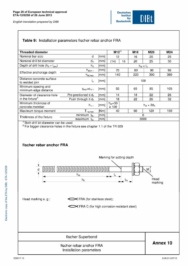
Elements made of reinforcing bars shall comply with the specifications given in Annex 9.
The marking of embedment depth may be done on jobsite.
2.2 Methods of verification
The assessment of fitness of the anchor for the intended use in relation to the requirements for mechanical resistance and stability and safety in use in the sense of the Essential Requirements 1 and 4 has been made in accordance with the "Guideline for European technical approval of Metal Anchors for Use in Concrete", Part 1 "Anchors in general" and Part 5 "Bonded anchors" on the basis of Option 1 and ETAG 001 Annex E "Assessment of Metal Anchors under Seismic Action".
In addition to the specific clauses relating to dangerous substances contained in this European technical approval, there may be other requirements applicable to the products falling within its scope (e.g. transposed European legislation and national laws, regulations and administrative provisions). In order to meet the provisions of the Construction Products Directive, these requirements need also to be complied with, when and where they apply.
3 Evaluation and attestation of conformity and CE marking
3.1 System of attestation of conformity
According to the decision 96/582/EG of the European Commission8 the system 2(i) (referred to as system 1) of attestation of conformity applies.
This system of attestation of conformity is defined as follows:
System 1: Certification of the conformity of the product by an approved certification body on the basis of:
(a) Tasks for the manufacturer:
(1) factory production control;
(2) further testing of samples taken at the factory by the manufacturer in accordance with a prescribed control plan;
(b) Tasks for the approved body:
(3) initial type-testing of the product;
(4) initial inspection of factory and of factory production control;
(5) continuous surveillance, assessment and approval of factory production control.
Note: Approved bodies are also referred to as "notified bodies".
8 Official Journal of the European Communities L 254 of 08.10.1996.
Ele
ctro
nic
copy
of t
he E
TA b
y D
IBt:
ETA
-12/
0258
European technical approval ETA-12/0258 English translation prepared by DIBt
Page 6 of 37 | 26 June 2013
Z36351.13 8.06.01-237/13
3.2 Responsibilities
3.2.1 Tasks of the manufacturer
3.2.1.1 Factory production control
The manufacturer shall exercise permanent internal control of production. All the elements, requirements and provisions adopted by the manufacturer shall be documented in a systematic manner in the form of written policies and procedures, including records of results performed. This production control system shall insure that the product is in conformity with this European technical approval.
The manufacturer may only use initial / raw / constituent materials stated in the technical documentation of this European technical approval.
The factory production control shall be in accordance with the control plan relating to this European technical approval which is part of the technical documentation of this European technical approval. The control plan is laid down in the context of the factory production control system operated by the manufacturer and deposited at Deutsches Institut für Bautechnik.9
The results of factory production control shall be recorded and evaluated in accordance with the provisions of the control plan.
3.2.1.2 Other tasks of manufacturer
The manufacturer shall, on the basis of a contract, involve a body which is approved for the tasks referred to in section 3.1 in the field of anchors in order to undertake the actions laid down in section 3.3. For this purpose, the control plan referred to in sections 3.2.1.1 and 3.2.2 shall be handed over by the manufacturer to the approved body involved.
The manufacturer shall make a declaration of conformity, stating that the construction product is in conformity with the provisions of this European technical approval.
3.2.2 Tasks of approved bodies
The approved body shall perform the
- initial type-testing of the product,
- initial inspection of factory and of factory production control,
- continuous surveillance, assessment and approval of factory production control
in accordance with the provisions laid down in the control plan relating to this European technical approval.
The approved body shall retain the essential points of its actions referred to above and state the results obtained and conclusions drawn in a written report.
The approved certification body involved by the manufacturer shall issue an EC certificate of conformity of the product stating the conformity with the provisions of this European technical approval.
In cases where the provisions of the European technical approval and its control plan are no longer fulfilled the certification body shall withdraw the certificate of conformity and inform Deutsches Institut für Bautechnik without delay.
9 The control plan is a confidential part of the European technical approval and only handed over to the approved body
involved in the procedure of attestation of conformity. See section 3.2.2.
Ele
ctro
nic
copy
of t
he E
TA b
y D
IBt:
ETA
-12/
0258
European technical approval ETA-12/0258 English translation prepared by DIBt
Page 7 of 37 | 26 June 2013
Z36351.13 8.06.01-237/13
3.3 CE marking
The CE marking shall be affixed on each packaging of the anchor. The letters "CE" shall be followed by the identification number of the approved certification body, where relevant, and be accompanied by the following additional information:
- the name and address of the producer (legal entity responsible for the manufacture),
- the last two digits of the year in which the CE marking was affixed,
- the number of the EC certificate of conformity for the product,
- the number of the European technical approval,
- the number of the guideline for European technical approval,
- use category (ETAG 001-1 Option 1, in addition: seismic performance category C1 – where applicable),
- size.
4 Assumptions under which the fitness of the product for the intended use was favourably assessed
4.1 Manufacturing
The European technical approval is issued for the product on the basis of agreed data/information, deposited with Deutsches Institut für Bautechnik, which identifies the product that has been assessed and judged. Changes to the product or production process, which could result in this deposited data/information being incorrect, should be notified to Deutsches Institut für Bautechnik before the changes are introduced. Deutsches Institut für Bautechnik will decide whether or not such changes affect the European technical approval and consequently the validity of the CE marking on the basis of the European technical approval and if so whether further assessment or alterations to the European technical approval shall be necessary.
4.2 Design of anchorages
The fitness of the anchor for the intended use is given under the following conditions:
The anchorages are designed in accordance with the EOTA Technical Report TR 029 "Design of bonded anchors"10 and EOTA Technical Report TR 045 "Design of Metal Anchors under Seismic Action" under the responsibility of an engineer experienced in anchorages and concrete work.
Anchorages shall be positioned outside of critical regions (e.g. plastic hinges) of the concrete structure. Fastenings in stand-off installation or with a grout layer under seismic action are not covered by this European technical approval.
10
The Technical Report TR 029 "Design of Bonded Anchors" is published in English on EOTA website www.eota.eu.
Ele
ctro
nic
copy
of t
he E
TA b
y D
IBt:
ETA
-12/
0258
European technical approval ETA-12/0258 English translation prepared by DIBt
Page 8 of 37 | 26 June 2013
Z36351.13 8.06.01-237/13
Post-installed reinforcing bars may be used as anchor designed in accordance with the EOTA Technical Report TR 029 and TR 045 only. The basic assumptions for the design according to anchor theory shall be observed. This includes the consideration of tension and shear loads and the corresponding failure modes as well as the assumption that the base material (concrete structural element) remains essentially in the serviceability limit state (either non-cracked or cracked) when the connection is loaded to failure. Such applications are e.g. concrete overlay or shear dowel connections or the connections of a wall predominantly loaded by shear and compression forces with the foundation, where the reinforcing bars act as dowels to take up shear forces. Connections with reinforcing bars in concrete structures designed in accordance with EN 1992-1-1:2004 (e.g. connection of a wall loaded with tension forces in one layer of the reinforcement with the foundation) are not covered by this European technical approval.
Verifiable calculation notes and drawings are prepared taking account of the loads to be anchored.
For the fischer internal threaded anchor RG MI fastening screws or threaded rods made of appropriate steel and strength class acc. to Annex 8 shall be specified. The minimum and maximum thread engagement length lE of the fastening screw or the threaded rod for installation of the fixture shall be met the requirements according to Annex 6, Table 3. The length of the fastening screw or the threaded rod shall be determined depending on thickness of fixture, admissible tolerances, available thread length and minimum and maximum thread engagement length lE.
The position of the anchor is indicated on the design drawings (e.g. position of the anchor relative to reinforcement or to supports, etc.).
4.3 Installation of anchors
The fitness for use of the anchor can only be assumed if the anchor is installed as follows:
- anchor installation carried out by appropriately qualified personnel and under the supervision of the person responsible for technical matters of the site,
- use of the anchor only as supplied by the manufacturer without exchanging the components of an anchor,
- anchor installation in accordance with the manufacturer’s specifications and drawings using the tools indicated in the technical documentation of this European technical approval,
- For use of the injection mortar fischer FIS SB, fischer FIS SB High Speed and fischer FIS SB Low speed commercial standard threaded rods, washers and hexagon nuts may also be used if the following requirements are fulfilled:
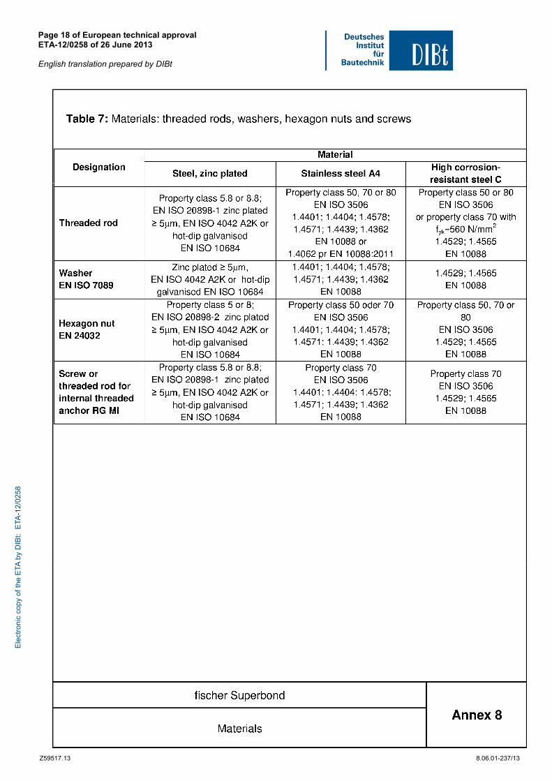
• material, dimensions and mechanical properties of the metal parts according to the specifications given in Annex 8, Table 7,
• confirmation of material and mechanical properties of the metal parts by inspection certificate 3.1 according to EN 10204:2004, the documents should be stored,
• marking of the threaded rod with the envisage embedment depth. This may be done by the manufacturer of the rod or the person on jobsite.
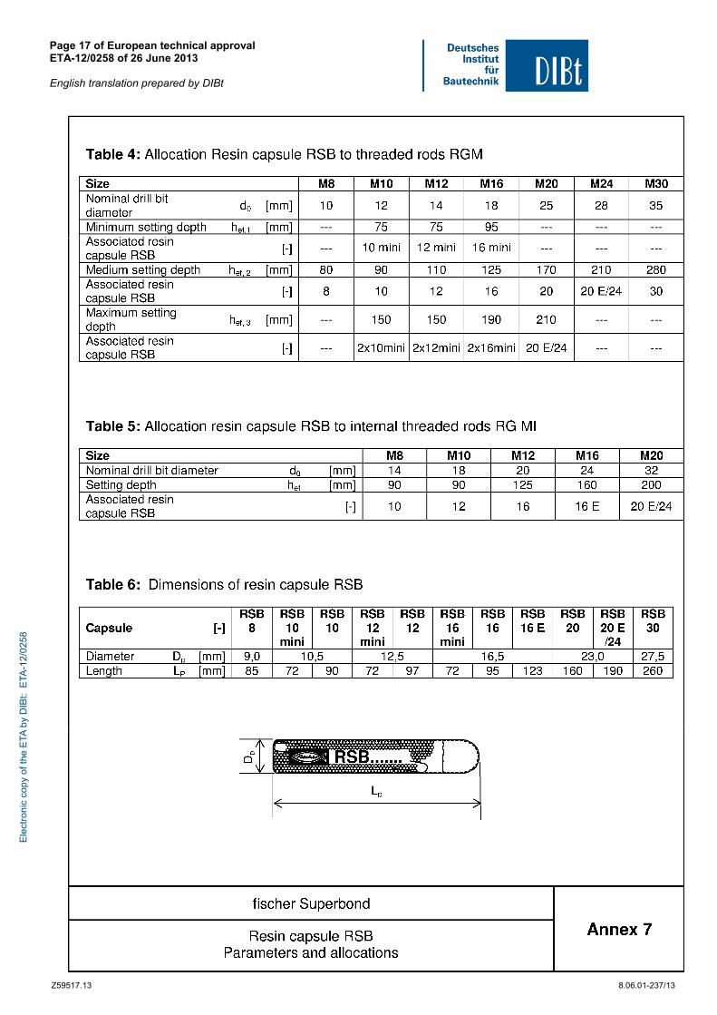
- fischer resin capsules RSB may only be used with corresponding fischer threaded rods RGM,
- reinforcing bars shall comply with specifications given in Annex 9,
- checks before placing the anchor to ensure that the strength class of the concrete in which the anchor is to be placed is in the range given and is not lower than that of the concrete to which the characteristic loads apply,
- check of concrete being well compacted, e.g. without significant voids,
Ele
ctro
nic
copy
of t
he E
TA b
y D
IBt:
ETA
-12/
0258
European technical approval ETA-12/0258 English translation prepared by DIBt
Page 9 of 37 | 26 June 2013
Z36351.13 8.06.01-237/13
- marking and keeping the effective anchorage depth,
- edge distance and spacing not less than the specified values without minus tolerances,
- positioning of the drill holes without damaging the reinforcement,
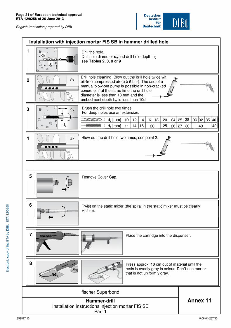
- drill holes for the cartridge injection system must be made by hammer drilling only,
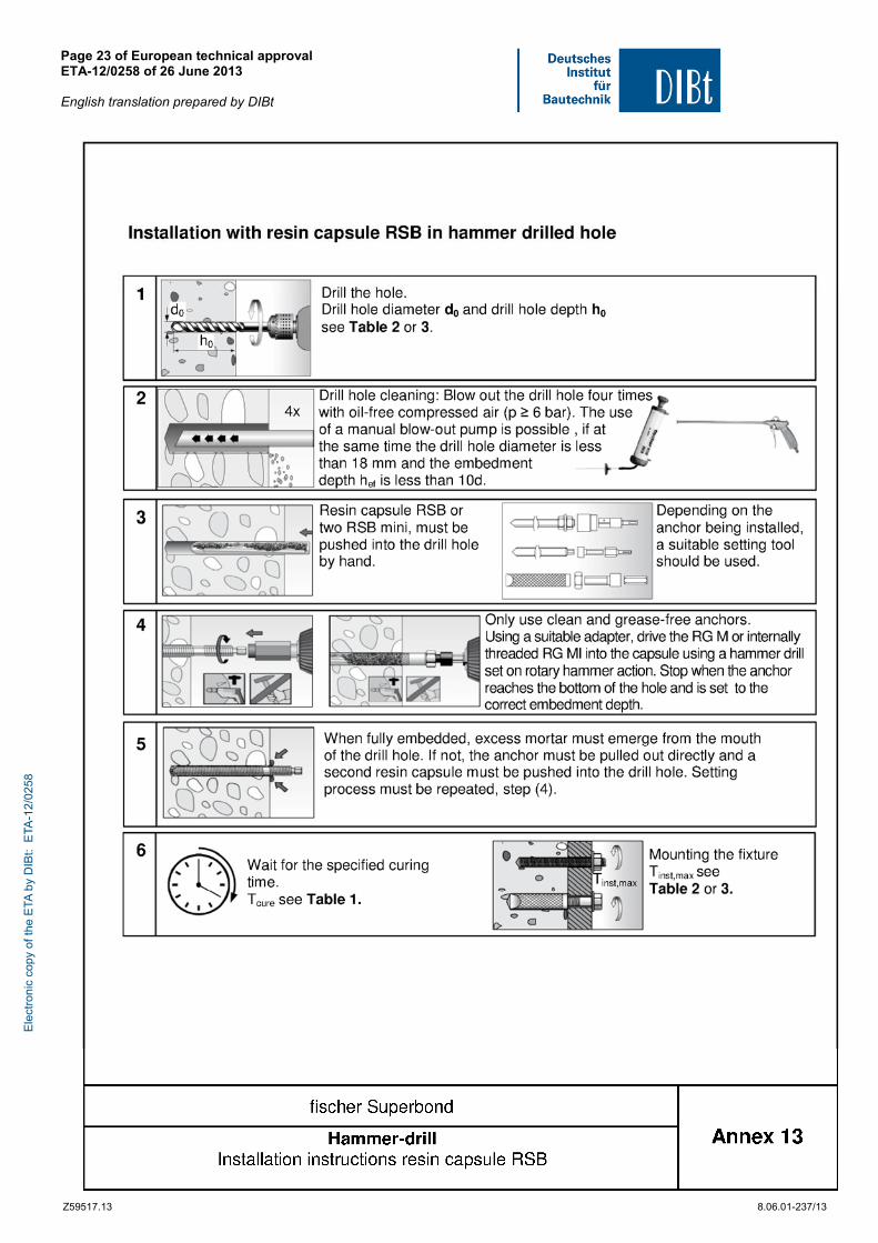
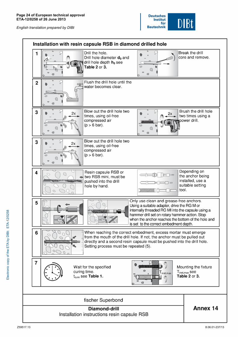
- drill holes for the capsule system by hammer drilling or diamond drilling,
- in case of aborted hole: The hole shall be filled with mortar,
- the cartridge injection system must not be installed in flooded holes,
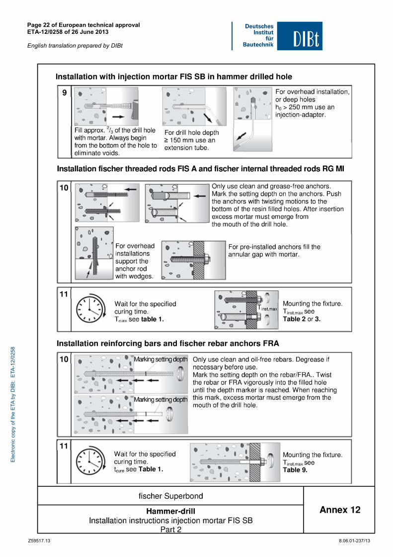
- cleaning the drill hole and installation in accordance with Annexes 11 to 14,
- if the anchor is proper installed mortar must be visible at the member surface.
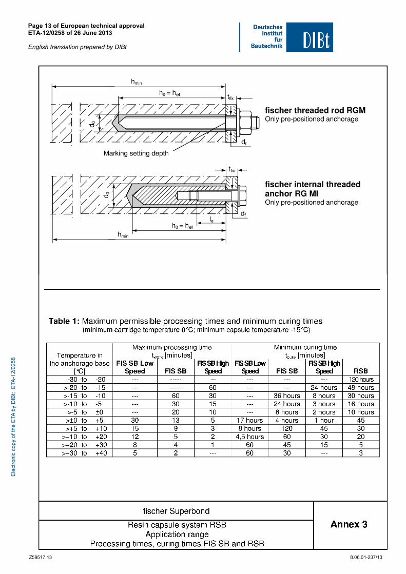
- the anchor component installation temperature shall be at least 0 °C when using the injection system FIS SB and -15 °C when using the capsule system RSB,
- during curing of the mortar the temperature of the concrete must not fall below 0°C for the injection mortar FIS SB Low Speed,
- during curing of the mortar the temperature of the concrete must not fall below -15 °C for the injection mortar FIS SB,
- during curing of the mortar the temperature of the concrete must not fall below -20 °C for the injection mortar FIS SB High Speed,
- during curing of the mortar the temperature of the concrete must not fall below -30 °C for the capsule system RSB,
- the curing time until the anchor may be loaded as given in Annex 3, Table 1 has to be observed,
- installation torque moments are not required for functioning of the anchor. However, the torque moments given in the Annexes must not be exceeded.
5 Indications to the manufacturer
5.1 Responsibility of the manufacturer
The manufacturer is responsible to ensure that the information on the specific conditions according to section 1 and 2 including Annexes referred to as well as sections 4.2, 4.3 and 5.2 is given to those who are concerned. This information may be made by reproduction of the respective parts of the European technical approval. In addition all installation data shall be shown clearly on the package and/or on an enclosed instruction sheet, preferably using illustration(s).
The minimum data required are:
- diameter of drill bit,
- hole depth,
- diameter of anchor rod,
- minimum effective anchorage depth,
- maximum thickness of the fixture,
- information on the installation procedure, including cleaning of the hole with the cleaning equipments, preferably by means of an illustration,
- temperature of anchor components while installation,
- ambient temperature of the concrete during installation of the anchor,
- admissible processing time (open time) of a cartridge,
Ele
ctro
nic
copy
of t
he E
TA b
y D
IBt:
ETA
-12/
0258
European technical approval ETA-12/0258 English translation prepared by DIBt
Page 10 of 37 | 26 June 2013
Z36351.13 8.06.01-237/13
- curing time until the anchor may be loaded as a function of the ambient temperature in the concrete during installation,
- installation torque moment,
- identification of the manufacturing batch. All data shall be presented in a clear and explicit form.
5.2 Packaging, transport and storage
The mortar cartridges and the capsules shall be protected against sun radiation and shall be stored according to the manufacturer instructions in dry condition at temperatures of at least +5 °C to not more than +25 °C (Short time storage up to +35 °C is admissible).
Mortar cartridges and glass capsules with expired shelf life must no longer be used.
The anchor shall only be packaged and supplied as a complete unit. Mortar cartridges and capsules may be packed separately from metal parts.
The manufacturer's installation instruction shall indicate that the mortar cartridges and capsules can be used only with the corresponding steel elements.
Uwe Bender beglaubigt:
Head of Department Lange
Ele
ctro
nic
copy
of t
he E
TA b
y D
IBt:
ETA
-12/
0258
Page 11 of European technical approval ETA-12/0258 of 26 June 2013 English translation prepared by DIBt
Z59517.13 8.06.01-237/13
Ele
ctro
nic
copy
of t
he E
TA b
y D
IBt:
ETA
-12/
0258
Page 12 of European technical approval ETA-12/0258 of 26 June 2013 English translation prepared by DIBt
Z59517.13 8.06.01-237/13
Ele
ctro
nic
copy
of t
he E
TA b
y D
IBt:
ETA
-12/
0258
Page 13 of European technical approval ETA-12/0258 of 26 June 2013 English translation prepared by DIBt
Z59517.13 8.06.01-237/13
Ele
ctro
nic
copy
of t
he E
TA b
y D
IBt:
ETA
-12/
0258
Page 14 of European technical approval ETA-12/0258 of 26 June 2013 English translation prepared by DIBt
Z59517.13 8.06.01-237/13
Ele
ctro
nic
copy
of t
he E
TA b
y D
IBt:
ETA
-12/
0258
Page 15 of European technical approval ETA-12/0258 of 26 June 2013 English translation prepared by DIBt
Z59517.13 8.06.01-237/13
Ele
ctro
nic
copy
of t
he E
TA b
y D
IBt:
ETA
-12/
0258
Page 16 of European technical approval ETA-12/0258 of 26 June 2013 English translation prepared by DIBt
Z59517.13 8.06.01-237/13
Ele
ctro
nic
copy
of t
he E
TA b
y D
IBt:
ETA
-12/
0258
Page 17 of European technical approval ETA-12/0258 of 26 June 2013 English translation prepared by DIBt
Z59517.13 8.06.01-237/13
Ele
ctro
nic
copy
of t
he E
TA b
y D
IBt:
ETA
-12/
0258
Page 18 of European technical approval ETA-12/0258 of 26 June 2013 English translation prepared by DIBt
Z59517.13 8.06.01-237/13
Ele
ctro
nic
copy
of t
he E
TA b
y D
IBt:
ETA
-12/
0258
Page 19 of European technical approval ETA-12/0258 of 26 June 2013 English translation prepared by DIBt
Z59517.13 8.06.01-237/13
Ele
ctro
nic
copy
of t
he E
TA b
y D
IBt:
ETA
-12/
0258
Page 20 of European technical approval ETA-12/0258 of 26 June 2013 English translation prepared by DIBt
Z59517.13 8.06.01-237/13
Ele
ctro
nic
copy
of t
he E
TA b
y D
IBt:
ETA
-12/
0258
Page 21 of European technical approval ETA-12/0258 of 26 June 2013 English translation prepared by DIBt
Z59517.13 8.06.01-237/13
Ele
ctro
nic
copy
of t
he E
TA b
y D
IBt:
ETA
-12/
0258
Page 22 of European technical approval ETA-12/0258 of 26 June 2013 English translation prepared by DIBt
Z59517.13 8.06.01-237/13
Ele
ctro
nic
copy
of t
he E
TA b
y D
IBt:
ETA
-12/
0258
Page 23 of European technical approval ETA-12/0258 of 26 June 2013 English translation prepared by DIBt
Z59517.13 8.06.01-237/13
Ele
ctro
nic
copy
of t
he E
TA b
y D
IBt:
ETA
-12/
0258
Page 24 of European technical approval ETA-12/0258 of 26 June 2013 English translation prepared by DIBt
Z59517.13 8.06.01-237/13
Ele
ctro
nic
copy
of t
he E
TA b
y D
IBt:
ETA
-12/
0258
Page 25 of European technical approval ETA-12/0258 of 26 June 2013 English translation prepared by DIBt
Z59517.13 8.06.01-237/13
Ele
ctro
nic
copy
of t
he E
TA b
y D
IBt:
ETA
-12/
0258
Page 26 of European technical approval ETA-12/0258 of 26 June 2013 English translation prepared by DIBt
Z59517.13 8.06.01-237/13
Ele
ctro
nic
copy
of t
he E
TA b
y D
IBt:
ETA
-12/
0258
Page 27 of European technical approval ETA-12/0258 of 26 June 2013 English translation prepared by DIBt
Z59517.13 8.06.01-237/13
Ele
ctro
nic
copy
of t
he E
TA b
y D
IBt:
ETA
-12/
0258
Page 28 of European technical approval ETA-12/0258 of 26 June 2013 English translation prepared by DIBt
Z59517.13 8.06.01-237/13
Ele
ctro
nic
copy
of t
he E
TA b
y D
IBt:
ETA
-12/
0258
Page 29 of European technical approval ETA-12/0258 of 26 June 2013 English translation prepared by DIBt
Z59517.13 8.06.01-237/13
Ele
ctro
nic
copy
of t
he E
TA b
y D
IBt:
ETA
-12/
0258

Page 30 of European technical approval ETA-12/0258 of 26 June 2013 English translation prepared by DIBt
Z59517.13 8.06.01-237/13
Ele
ctro
nic
copy
of t
he E
TA b
y D
IBt:
ETA
-12/
0258
Page 31 of European technical approval ETA-12/0258 of 26 June 2013 English translation prepared by DIBt
Z59517.13 8.06.01-237/13
Ele
ctro
nic
copy
of t
he E
TA b
y D
IBt:
ETA
-12/
0258
Page 32 of European technical approval ETA-12/0258 of 26 June 2013 English translation prepared by DIBt
Z59517.13 8.06.01-237/13
Ele
ctro
nic
copy
of t
he E
TA b
y D
IBt:
ETA
-12/
0258
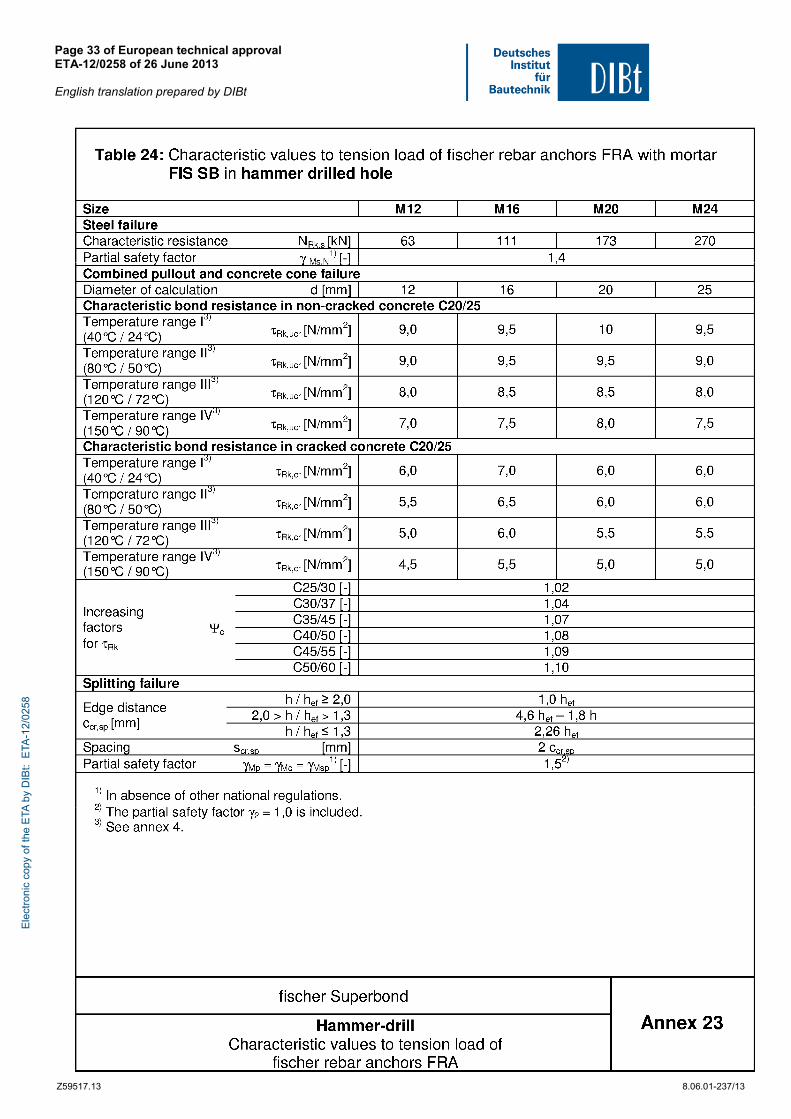
Page 33 of European technical approval ETA-12/0258 of 26 June 2013 English translation prepared by DIBt
Z59517.13 8.06.01-237/13
Ele
ctro
nic
copy
of t
he E
TA b
y D
IBt:
ETA
-12/
0258
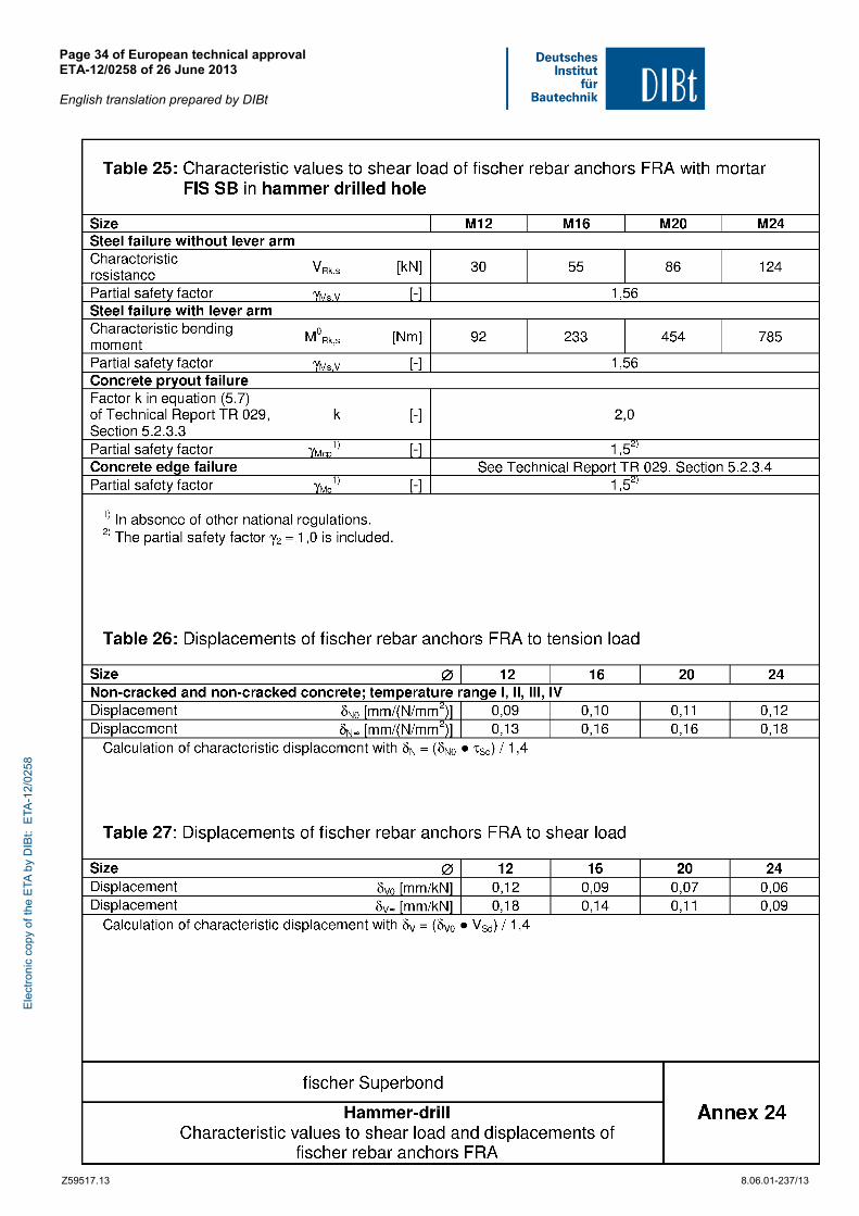
Page 34 of European technical approval ETA-12/0258 of 26 June 2013 English translation prepared by DIBt
Z59517.13 8.06.01-237/13
Ele
ctro
nic
copy
of t
he E
TA b
y D
IBt:
ETA
-12/
0258
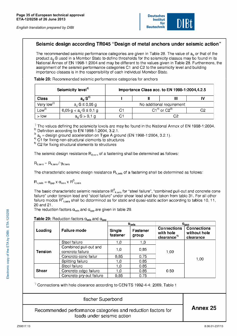
Page 35 of European technical approval ETA-12/0258 of 26 June 2013 English translation prepared by DIBt
Z59517.13 8.06.01-237/13
Ele
ctro
nic
copy
of t
he E
TA b
y D
IBt:
ETA
-12/
0258
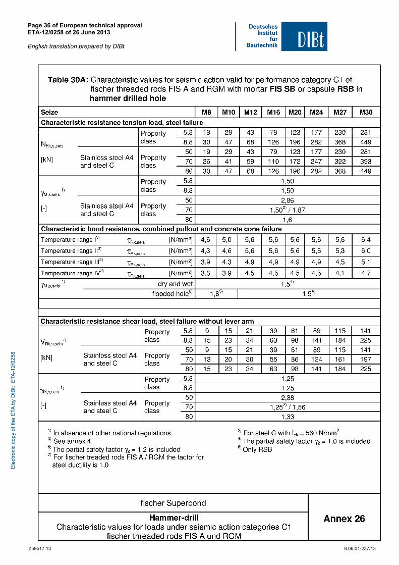
Page 36 of European technical approval ETA-12/0258 of 26 June 2013 English translation prepared by DIBt
Z59517.13 8.06.01-237/13
Ele
ctro
nic
copy
of t
he E
TA b
y D
IBt:
ETA
-12/
0258
Page 37 of European technical approval ETA-12/0258 of 26 June 2013 English translation prepared by DIBt
Z59517.13 8.06.01-237/13
Ele
ctro
nic
copy
of t
he E
TA b
y D
IBt:
ETA
-12/
0258