Embed Size (px)
Citation preview
TECHNISCHE UNIVERSITÄT MÜNCHEN
Lehrstuhl für Turbomaschinen und Flugantriebe
Evaluation of the Potential of Recuperator on a 300-kW Turboshaft
Helicopter Engine
Chengyu Zhang
Vollständiger Abdruck der von der Fakultät für Maschinenwesen der Technischen
Universität München zur Erlangung des akademischen Grades eines
Doktor -Ingenieurs
genehmigten Dissertation.
Vorsitzender: Prof. Dr.-Ing. Hartmut Spliethoff
Prüfer der Dissertation:
1. Prof. Dr.-Ing. Volker Gümmer
2. Prof. Dr.-Ing. Harald Klein
Die Dissertation wurde am 14.11.2019 bei der Technischen Universität München
eingereicht und durch die Fakultät für Maschinenwesen am 30.03.2020 angenommen.


I
Acknowledgements
During preparing this dissertation I have received a great deal of kind support and help
from many individuals. I would like to extend my profound appreciation to all of them.
First of all, I owe my deepest gratitude to my doctoral supervisor Prof. Volker Gümmer
for his dedication and keen interest in this study, for the continuous support and
illuminating discussions throughout the project. Without his sincere guidance and help,
this dissertation would not have been possible. Besides that, I also want to thank Prof.
Haidn and Prof. Hupfer for giving me the opportunity to work at the Chair of
Turbomachinery and Flight Propulsion. In addition, special thanks go to Prof. Harald
Klein for being my second examiner, and Prof. Hartmut Spliethoff for serving as the
committee chair.
I am indebted to Dr. Wolfgang Erhard for providing technical data about Allison
turboshaft engine, my colleague Martin Kerler for the stimulating discussions, and
Christian Schäffer and Julian Pauw for software support. I further owe gratitude to Oliver
Weiß, Philipp Zofer, Tobias Schmidt, Jannik Eckel, Mattia Straccia, Fabian Fuchs, Ilaria
De Dominicis, Thorsten Reiter, Marcel Schmieder, Michael Hopfinger, Christian Köhler,
Patrick Polte, Sina Eisenmann, Sebastian Lang, Anna Zimmermann, Meng Luo,
Zhendong Yu, Hao Ma, Hongxin Wang, Jianing Liu, Yongchuan Yu who have provided
great company during my staying in Munich. Also I’m grateful to Ye Hong who has
helped me in multiple aspects during these four years.
Finally, I would like to thank my parents, sister and girlfriend who have always provided
passionate encouragement, supported me with love and understanding. It is so wonderful
to have them with me through every single step of this special journey.

II
III
Zusammenfassung
Die ständig zunehmenden Anforderungen im 21. Jhd. an die Entwicklung hocheffizienter,
umweltfreundlicher Flugzeug-Triebwerke fordert den Einsatz von Rekuperatoren mit
reduziertem Kraftstoffeinsatz, geringeren Emissionen und gedämpften
Motorengeräuschen. Dies ist vor allem für Drehflügler-Triebwerke von Interesse, da
diese im Einsatz mehr als 60% in Teillast betrieben werden. Dabei liegen ineffiziente
spezifische Kraftstoffverbrauchseigenschaften vor. Die vorliegende Arbeit betreibt zuerst
eine Aufarbeitung von vorherigen Entwicklungsarbeiten rekuperierender Helikopter-
Turbowellenmotoren, gefolgt von der aktuellen Bedeutung der gesammelten Erfahrung
und der aktuellen Forschung an drei Haupttypen von Wärmetauschern, nämlich
rohrförmig, primäre Oberfläche und Platten-Rippen. Auf dieser Basis sollen
Wärmetauscher für den potenziellen Einsatz als Drehflüglertriebwerksrekuperatoren mit
aktuellen oder zukünftigen Technologien gefunden werden.
In der nächsten Phase dieser Arbeit wurde ein Prozess für die integrierte multidisziplinäre
Simulation von Drehflüglern entwickelt, um umfassende Aussagen zur Systemleistung
bei Verwendung von rohrförmigen Rekuperatoren oder Rekuperatoren mit primärer
Oberfläche während des Einsatzes treffen zu können. Ein allgemeines Drehflügler-
Modell wurde bezogen auf einen Mehrzweckhelikopter Bo105 betrieben mit zwei Allison
250-C20B Turbowellen-Motoren analysiert. Durch den Einsatz eines Rekuperators
konnte eine wesentliche Reduktion des Kraftstoffverbrauchs erzielt werden. Die
vorgeschlagene Methodik ist anschließend erweitert worden, um das Potenzial von
Drehflüglern mit Rekuperator unter dem Hauptgesichtspunkt von hocheffizienten
Rekuperatoren mit primärer Oberfläche bei Flugbedingungen von 0 – 250 km/h und 0 –
3000 m zu analysieren. Die gewonnenen Ergebnisse deuten darauf hin, dass eine hohe
Effektivität unter bestimmten Einsatzbedingungen (besonders bei Einsätzen auf kurzen
Distanzen) bei Berücksichtigung des gegebenen dramatischen Gewichtsanstiegs für den
weiteren Rekuperatorentwurf nicht geeignet sein könnte.
Nach Optimierung mit mehreren Zielfunktionen mittels der Implementierung eines
Genetischen Algorithmus (GA) wurde das Pareto Front Modell abgeleitet, um die
verbundenen Zwischenabhängigkeiten und den Zielkonflikt zwischen dem Potenzial zur
Kraftstoffeinsparung und der Gewichtsbelastung durch den Rekuperator zu erfassen. Vier
optimale Entwurfslösungen wurden ausgewählt und für drei repräsentative

IV
Helikoptereinsätze simuliert. Ein optimaler Kompromiss stellte sich für eine
Rekuperator-Effizienz von 76,1% und einem Gewicht von 27,48 kg ein. Die
vorgeschlagene Methodik kann also ein zeiteffizientes Werkzeug für die umfassende
Betrachtung von Drehflüglerantriebssystemen in Verbindung mit potenziell geeigneten
hocheffizienten Rekuperatoren hinsichtlich multidisziplinärem Entwurf und Optimierung
darstellen.
V
Abstract
The increasingly demanding requirements for developing highly efficient,
environmentally friendly aero-engines in the 21st century highlights the utilization of
recuperators with reduced fuel burn, lower emissions and attenuated engine noise. This is
particularly attractive for rotorcraft powerplants, as more than 60% of the mission time is
spent at part load, which shows non-optimum specific fuel consumption (SFC)
characteristics. The present work first conducts an elaborated investigation on previous
development work of recuperated helicopter turboshaft engines, and followed by the
relevance of accumulated experience, as well as recent research on three main kinds of
heat exchanger candidates, i.e. tubular, primary surface and plate fin, it seeks to find heat
exchangers potentially applicable to rotorcraft recuperators with technologies prevailing
to date or in the near future.
In the next phase of this work, an integrated rotorcraft multidisciplinary simulation
framework has been developed to comprehensively assess the system performance of the
rotorcraft adopting tubular or primary surface recuperator at mission levels. A generic
rotorcraft model is analyzed based on a typical multi-purpose utility helicopter Bo105
powered by two Allison 250-C20B turboshaft engines. A substantial amount of fuel burn
reduction is realized with the adoption of recuperator. The proposed methodology is then
further extended to evaluate the potential of recuperated rotorcraft with prime focus on
highly effective primary surface recuperator under the flight condition of 0-250 km/h and
0-3000 m. The obtained results suggest that the selection of high value of effectiveness
may not be suitable in certain cases (especially short range missions) for further
recuperator design considering the inherited dramatic growth in weight penalty.
Through the execution of multi-objective genetic algorithm (GA) optimization, the Pareto
front model is derived qualifying the associated interdependency and trade-off between
the fuel saving potential and recuperator weight penalty. Four optimal design solutions
are selected, and simulated for three representative helicopter missions. The optimum
trade-off is attained for the employed recuperator effectiveness of 76.1% with the weight
of 27.48 kg. The proposed methodology could be a cost-effective and computationally
efficient tool for the comprehensive assessment of the rotorcraft powerplant system
incorporating a potentially suitable, high performance recuperator, with regards to
multidisciplinary design and optimization.

VI
1
Contents
Acknowledgements .................................................................................................................. I
Zusammenfassung ................................................................................................................ III
Abstract ..................................................................................................................................V
Contents .................................................................................................................................. 1
Nomenclature ......................................................................................................................... 3
List of Figures......................................................................................................................... 7
List of Tables .......................................................................................................................... 9
1. Introduction ...................................................................................................................... 11
1.1 Background .................................................................................................................. 11
1.2 Research objectives ...................................................................................................... 13
1.3 Thesis outline ............................................................................................................... 14
2. High temperature heat exchangers for recuperated rotorcraft powerplants ................. 15
2.1 Development of recuperated turboshaft engine concepts ............................................... 15
2.1.1 Previous development activities ................................................................................ 15
2.1.2 Performance projection for turboshaft engines .......................................................... 24
2.2 Types of candidate recuperators .................................................................................... 25
2.2.1 Plate-fin geometry .................................................................................................... 26
2.2.2 Primary-surface geometry ......................................................................................... 26
2.2.3 Tubular geometry ..................................................................................................... 29
2.3 Comparison of recuperators ............................................................................................ 30
2.4 Material selection and manufacturing technology .......................................................... 32
2.5 Summary of recuperator technology status .................................................................... 35
3. Performance evaluation of recuperated rotorcraft powerplants .................................... 37
3.1 Trade-off between improved fuel economy and parasitic recuperator weight ................. 37
3.2 System modeling .......................................................................................................... 38
3.2.1 System simulation framework ................................................................................... 38
3.2.2 Recuperator weight estimation .................................................................................. 41
3.2.3 Helicopter performance prediction ............................................................................ 42
3.2.4 GasTurb engine performance .................................................................................... 45
2
3.2.5 Recuperated turboshaft engine .................................................................................. 48
3.3 Mission investigation .................................................................................................... 50
3.3.1 Generic mission analysis ........................................................................................... 52
3.3.2 Representative mission analysis ................................................................................ 55
3.4 Summary ...................................................................................................................... 62
4. The potential of rotorcraft powerplant incorporating highly effective recuperators ... 64
4.1 Highly effective primary surface recuperator................................................................. 64
4.2 Recuperator volume estimation ..................................................................................... 65
4.3 Recuperated engine part-load performance.................................................................... 68
4.4 Various flight conditions............................................................................................... 70
4.4.1 Comparison analysis ................................................................................................. 70
4.4.2 Fuel saving potential investigation ............................................................................ 73
4.5 Recuperator installation consideration ........................................................................... 76
4.6 Summary ...................................................................................................................... 77
5. Multi-objective design and optimization of recuperator ................................................. 79
5.1 Research background .................................................................................................... 79
5.2 Characteristic parameters of PSR .................................................................................. 82
5.3 Simulation methodology ............................................................................................... 84
5.3.1 Physical model and thermodynamic calculation ........................................................ 84
5.3.2 Multi-objective genetic algorithm optimization ......................................................... 88
5.3.3 Multidisciplinary simulation framework ................................................................... 89
5.4 Evaluation of heat transfer surfaces ............................................................................... 91
5.5 Multi-objective optimization ......................................................................................... 93
5.6 System evaluation ......................................................................................................... 95
5.7 Summary ...................................................................................................................... 98
6. Conclusions and outlooks ................................................................................................. 99
6.1 Summary and conclusions ...........................................................................................100
6.2 Outlooks ......................................................................................................................101
7. List of publications ..........................................................................................................103
7.1 Journal publications .....................................................................................................103
7.2 Peer-reviewed conference publications ........................................................................103
Bibliography ........................................................................................................................104
Appendix .............................................................................................................................116
A. Helicopter Bo105 data ..................................................................................................116
B. Allison 250-C20B simulation model .............................................................................117
3
Nomenclature
Acronyms
CC cross-corrugated
GA Genetic Algorithm
HPT high pressure turbine
NTU number of transfer units
ISA international standard atmosphere
LPT low pressure turbine
MSL mean sea level
MTOW maximum takeoff weight
OTS offshore transportation
PAT passenger air taxi
PSR primary surface recuperator
PSV police surveillance
PR pressure ratio
RC recuperated cycle
SAR search and rescue
SC simple cycle
SFC specific fuel consumption
SP specific power
TIT turbine inlet temperature
4
Symbols
𝐴 rotor disc area or heat transfer area [m
2]
𝐴𝑐 flow cross section area [m2]
𝐶∗ heat capacity ratio [-]
Cd0 profile drag coefficient [-]
CDS equivalent flat-plate area [m2]
cp specific heat [J/(kg∙ K)]
Dh hydraulic diameter [m]
f Fanning friction factor [-]
G gross mass [kg]
Garea area goodness factor [-]
Gvol volume goodness factor [-]
Hi internal height [m]
j Colburn factor [-]
𝐿1 width [m]
𝐿2 length [m]
𝐿3 height [m]
𝑚 mass flow rate [kg/s]
∆𝑀 weight difference [kg]
𝑁𝑢 Nusselt number [-]
𝑝 pressure [Pa]
𝑃 power or corrugation pitch [W] or [m]
Pr Prandtl number [-]
𝑆 wetted surface [m]
𝑆𝑡 Stanton number [-]
T temperature [K]
U overall heat transfer coefficient [-]
V internal volume of the unitary cell [m3]
Greek Symbols
δ wall thickness [m]
𝜃 corrugation inclination angle [°]
𝑘 empirical correction factor [-]
𝜌 air density [kg/m3]

5
ρm material density [kg/m3]
g gravitational acceleration [m/s2]
𝜎 rotor solidity [-]
𝜇 advance ratio or viscosity [-] or [Pa∙ s]
𝜈 velocity [m/s]
𝜂 efficiency [-]
λ thermal conductivity [W/(m∙ K)]
휀 effectiveness [-]
β surface compactness [-]
Subscripts
avi available
𝐴𝑢𝑥 auxiliary system
𝑑𝑠 design
f flight
ℎ flight altitude
i induced
mec mechanical
𝑀𝑅 main rotor
𝑜 profile
𝑝 parasitic
𝑟𝑒𝑞 required
sys system
𝑡 total
tip blade tip
TR tail rotor

6
7
List of Figures
Figure 1.1 A schematic illustration of the turboshaft engine [8] .................................................12
Figure 1.2 Schematic layout of a single-spool recuperated turboshaft engine [10] ....................13
Figure 2.1 Previous exploration of recuperated helicopter turboshaft engines ...........................16
Figure 2.2 a). T63 engine with twin tubular “bolt-on” recuperator modules, b). Recuperator
flow configuration [17] ......................................................................................................17
Figure 2.3 Recuperator tube matrix layout [35]..........................................................................18
Figure 2.4 Comparison of various flow arrangements ................................................................19
Figure 2.5 MTU recuperator and the U-shaped elliptic profiled tubes [49] ...............................20
Figure 2.6 a). Layout of the recuperated helicopter, b). An exploded view of the recuperator
[53] .....................................................................................................................................21
Figure 2.7 Simple cycle and recuperated turboshaft engine performance projection [57] .........25
Figure 2.8 Traditional primary surface geometries: a). cross corrugated (CC) surface, b).
corrugated undulated (CU) surface, c). cross wavy (CW) surface [82]..............................27
Figure 2.9 Configurations of modified primary surfaces with: a). anti-phase secondary
corrugation [85], b). in-phase secondary corrugation [85], c). full-wave rectified trough
corrugation [85], d). asymmetric profile [87], e). double-wave surface [89] and f).
corrugations [90] ................................................................................................................28
Figure 2.10 MTU profile tube recuperator module [93] .............................................................30
Figure 2.11 Ceramic microchannel recuperator matrix from Cermatec Inc [113] ......................34
Figure 2.12 The cross-section of the recuperated ceramic turboshaft engine [115] ...................35
Figure 3.1 The integrated rotorcraft multidisciplinary simulation framework ...........................39
Figure 3.2 The specific weight of gas turbine recuperator for different surface geometries [12].
............................................................................................................................................42
Figure 3.3 Analysis methodology block diagram of the HPCS ..................................................44
Figure 3.4 Power required for level flight at different altitudes .................................................45
Figure 3.5 Allison Engine instrumentation [123] .......................................................................46
Figure 3.6 Thermodynamic schematic of a simple Brayton cycle turboshaft engine .................47
Figure 3.7 Comparison results between simulation and experimental data [122] ......................47
Figure 3.8 Thermodynamic schematic of the recuperated turboshaft engine .............................49
Figure 3.9 The generic reference helicopter mission ..................................................................52
Figure 3.10 Delta fuel consumption versus 휀𝑑𝑠 for different mission ranges .............................53
Figure 3.11 The variation of ∆M versus mission time ................................................................54
8
Figure 3.12 Mission time required to research the equilibrium point for different 휀𝑑𝑠 values ...54
Figure 3.13 Mission segment information for selected missions................................................56
Figure 3.14 Trade-off results for PAT mission: a). Influence of 휀𝑑𝑠, b). Variation of ∆M ..........58
Figure 3.15 Trade-off results for PSV mission: a). Influence of 휀𝑑𝑠, b). Variation of ∆M ..........59
Figure 3.16 Trade-off results for SAR mission: a). Influence of 휀𝑑𝑠, b). Variation of ∆M .........60
Figure 3.17 Trade-off results for OTS mission: a). Influence of 휀𝑑𝑠, b). Variation of ∆M .........61
Figure 4.1 Gas turbine recuperator specific weight and volume tendency for primary surface
geometry (derived from Ref.[132]) ....................................................................................67
Figure 4.2 Design parameter study for turboshaft gas turbines with/without recuperator ..........69
Figure 4.3 The variation of SFC at various working load for different design effectiveness
(MSL, ISA conditions) .......................................................................................................69
Figure 4.4 The performance of recuperator at part load .............................................................70
Figure 4.5 Non-recuperated helicopter performance under various flight conditions ................72
Figure 4.6 Recuperated helicopter performance under various flight conditions (휀𝑑𝑠=80%).....73
Figure 4.7 Cruise flight time required to compensate the added recuperator weight (i.e. ∆M
=0) ......................................................................................................................................75
Figure 4.8 The internal structure of the engine bay with integrated engine model.....................76
Figure 5.1 General flow chart of recuperator optimization [82] .................................................81
Figure 5.2 a). Typical cross-corrugated (CC) plates, b). unitary cell [83] ..................................82
Figure 5.3 Schematic configuration of the V-shaped recuperator with two modules .................84
Figure 5.4 The flow chart of optimization process integrating the established thermal modeling.87
Figure 5.5 The integrated rotorcraft multidisciplinary simulation framework incorporated with
optimized recuperator .........................................................................................................91
Figure 5.6 Variation of goodness factors as function of Reynolds number for various
geometries, a). Gvol, b). Garea ..............................................................................................93
Figure 5.7 Multi-objective results, Pareto front for recuperator module weight and thermal
effectiveness with respect to two geometry candidates ......................................................94
Figure 5.8 Trade-off results in terms of saved mission fuel consumption and increased
parasitic recuperator weight, a). PAT mission, b). PSV mission, c). SAR mission ............96
9
List of Tables
Table 2.1 Primary features of previous investigated recuperated helicopter turboshaft engines
[1,12] ..................................................................................................................................18
Table 2.2 Comparison of high temperature metallic recuperator materials ................................33
Table 3.1 a). Reference helicopter characteristics, b). Engine design point parameters .............40
Table 3.2 Recuperator parameters with the designed effectiveness ............................................51
Table 3.3 Calculated results for all representative missions in terms of fuel consumption and
saving .................................................................................................................................57
Table 4.1 Recuperator weight and volume with the designed effectiveness ...............................67
Table 5.1 T Recuperator module design requirements ...............................................................85
Table 5.2 Comparisons between calculated results and Ref.[97]................................................86
Table 5.3 Different recuperator module design solutions in the optimal Pareto front with their
objective functions .............................................................................................................94

10
11
1. Introduction
1.1 Background
During these years, considerable progress has been made in the fields of combustion,
mechanical design, materials science and turbine components aerothermal improvement,
etc. which provides appealing performance for propulsion gas turbines including
turboshaft, turboprop, turbojet and turbofan [1-3]. However, after several decades of
development, it proves to be increasingly difficult to exploit the improvement potential in
the gas turbine systems merely on the basis of the simple thermodynamic cycle. Besides
that, the aero-industry has faced significant challenges from the beginning of the 21st
century, among which the most salient being the reduced emissions, improved SFC, less
noise and lower life cycle cost [4]. Advisory Council for Aerospace Research in Europe
(ACARE) suggested environmental targets for aero-engines, and based on the Clean Sky
program, a helicopter is expected to achieve a 26% reduction in CO2, a 65% cut in NOx, a
15% decline in specific fuel consumption (SFC), and halve the perceived aircraft noise by
2020 compared to the year 2000 [5]. In addition to environmental concerns, fuel
economy would also be of great importance for future aero engines development, taking
the MD 500E helicopter as an example, fuel and lubricants account for 28.6% (109.29$)
of the total direct operating cost, according to the estimated direct cost per hour in 2014
from MD Helicopters, Inc.[6]. As one of the most effective techniques to overcome these
challenges, adopting high performance heat exchangers are of great significance to meet
the growing demand for highly efficient, environmentally friendly aero-engines [7].
Turboshaft engines play a dominant role in helicopter propulsion, and they are adopted to
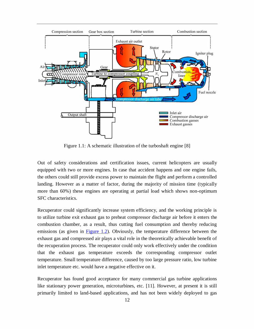
drive the main transmission and rotor systems. Figure 1.1 shows the schematic
illustration of a typical turboshaft engine and its common configuration. It presents a
conventional Brayton cycle which includes compression, combustion and turbine
expansion. Currently, turboshaft engines are normally of free power turbine configuration
with a single spool or in some cases two spool gas generators. Pressure ratio is usually in
the range 7 to 10, and turbine inlet temperature varies from about 1250 to 1450 K
requiring turbine blade cooling [9]. Larger turbine inlet temperature and higher pressure
ratio are expected for some medium and large turboshaft engines.
12
Figure 1.1: A schematic illustration of the turboshaft engine [8]
Out of safety considerations and certification issues, current helicopters are usually
equipped with two or more engines. In case that accident happens and one engine fails,
the others could still provide excess power to maintain the flight and perform a controlled
landing. However as a matter of factor, during the majority of mission time (typically
more than 60%) these engines are operating at partial load which shows non-optimum
SFC characteristics.
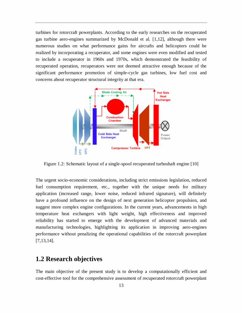
Recuperator could significantly increase system efficiency, and the working principle is
to utilize turbine exit exhaust gas to preheat compressor discharge air before it enters the
combustion chamber, as a result, thus cutting fuel consumption and thereby reducing
emissions (as given in Figure 1.2). Obviously, the temperature difference between the
exhaust gas and compressed air plays a vital role in the theoretically achievable benefit of
the recuperation process. The recuperator could only work effectively under the condition
that the exhaust gas temperature exceeds the corresponding compressor outlet
temperature. Small temperature difference, caused by too large pressure ratio, low turbine
inlet temperature etc. would have a negative effective on it.
Recuperator has found good acceptance for many commercial gas turbine applications
like stationary power generation, microturbines, etc. [11]. However, at present it is still
primarily limited to land-based applications, and has not been widely deployed to gas
13
turbines for rotorcraft powerplants. According to the early researches on the recuperated
gas turbine aero-engines summarized by McDonald et al. [1,12], although there were
numerous studies on what performance gains for aircrafts and helicopters could be
realized by incorporating a recuperator, and some engines were even modified and tested
to include a recuperator in 1960s and 1970s, which demonstrated the feasibility of
recuperated operation, recuperators were not deemed attractive enough because of the
significant performance promotion of simple-cycle gas turbines, low fuel cost and
concerns about recuperator structural integrity at that era.
Figure 1.2: Schematic layout of a single-spool recuperated turboshaft engine [10]
The urgent socio-economic considerations, including strict emissions legislation, reduced
fuel consumption requirement, etc., together with the unique needs for military
application (increased range, lower noise, reduced infrared signature), will definitely
have a profound influence on the design of next generation helicopter propulsion, and
suggest more complex engine configurations. In the current years, advancements in high
temperature heat exchangers with light weight, high effectiveness and improved
reliability has started to emerge with the development of advanced materials and
manufacturing technologies, highlighting its application in improving aero-engines
performance without penalizing the operational capabilities of the rotorcraft powerplant
[7,13,14].
1.2 Research objectives
The main objective of the present study is to develop a computationally efficient and
cost-effective tool for the comprehensive assessment of recuperated rotorcraft powerplant

14
systems in terms of operational performance under various flight condition as well as at
mission levels. The methodology deployed within this work could essentially be regarded
as an enabling technology to address the multidisciplinary design complexity and
interdependencies arising from the incorporation of high performance recuperator.
1.3 Thesis outline
The strategy of this work is given as follows:
Chapter 1 presents general information about the research background, objectives and
outline of this thesis.
In Chapter 2, it conducts an elaborated investigation on previous development work of
recuperated helicopter turboshaft engines, and followed by the relevance of accumulated
experience, as well as recent research on three main kinds of heat exchanger candidates,
i.e. tubular, primary surface and plate fin, it seeks to find heat exchangers potentially
applicable to rotorcraft recuperators with technologies prevailing to date or in the near
future.
In Chapter 3, an integrated rotorcraft multidisciplinary simulation framework, which
involves helicopter flight dynamics, engine performance, mission management and
recuperator weight estimation etc., is proposed and developed for the comprehensive
assessment of rotorcraft powerplant systems adopting tubular or primary surface
recuperators at helicopter mission levels.
For the next phase of this study, in Chapter 4, the potential of helicopter turboshaft
engines incorporating highly effective primary surface recuperators are evaluated under
various flight conditions (0-250 km/h and 0-3000 m). The improved part-load
performance against the reference non-recuperated cycle is also discussed, as well as the
recuperator size and installation considerations.
In Chapter 5, the established multidisciplinary simulation framework is further extended
through the employment of multi-objective genetic algorithm (GA) optimization for
recuperator design. Obtained optimal recuperator design solutions are evaluated under
typical mission scenarios. The overall approach and simulation methodology can be
effectively extended and applied to conduct multidisciplinary design and optimization for
recuperated rotorcraft powerplants.
15
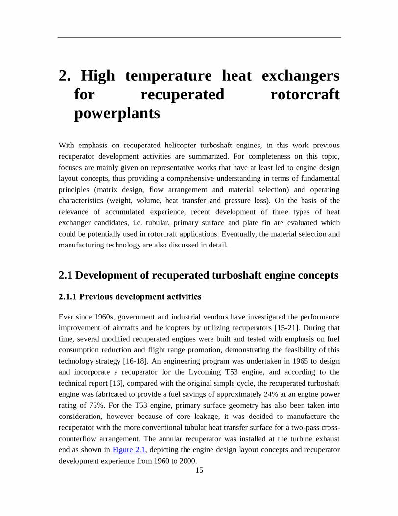
2. High temperature heat exchangers
for recuperated rotorcraft
powerplants
With emphasis on recuperated helicopter turboshaft engines, in this work previous
recuperator development activities are summarized. For completeness on this topic,
focuses are mainly given on representative works that have at least led to engine design
layout concepts, thus providing a comprehensive understanding in terms of fundamental
principles (matrix design, flow arrangement and material selection) and operating
characteristics (weight, volume, heat transfer and pressure loss). On the basis of the
relevance of accumulated experience, recent development of three types of heat
exchanger candidates, i.e. tubular, primary surface and plate fin are evaluated which
could be potentially used in rotorcraft applications. Eventually, the material selection and
manufacturing technology are also discussed in detail.
2.1 Development of recuperated turboshaft engine concepts
2.1.1 Previous development activities
Ever since 1960s, government and industrial vendors have investigated the performance
improvement of aircrafts and helicopters by utilizing recuperators [15-21]. During that
time, several modified recuperated engines were built and tested with emphasis on fuel
consumption reduction and flight range promotion, demonstrating the feasibility of this
technology strategy [16-18]. An engineering program was undertaken in 1965 to design
and incorporate a recuperator for the Lycoming T53 engine, and according to the
technical report [16], compared with the original simple cycle, the recuperated turboshaft
engine was fabricated to provide a fuel savings of approximately 24% at an engine power
rating of 75%. For the T53 engine, primary surface geometry has also been taken into
consideration, however because of core leakage, it was decided to manufacture the
recuperator with the more conventional tubular heat transfer surface for a two-pass cross-
counterflow arrangement. The annular recuperator was installed at the turbine exhaust
end as shown in Figure 2.1, depicting the engine design layout concepts and recuperator
development experience from 1960 to 2000.
16
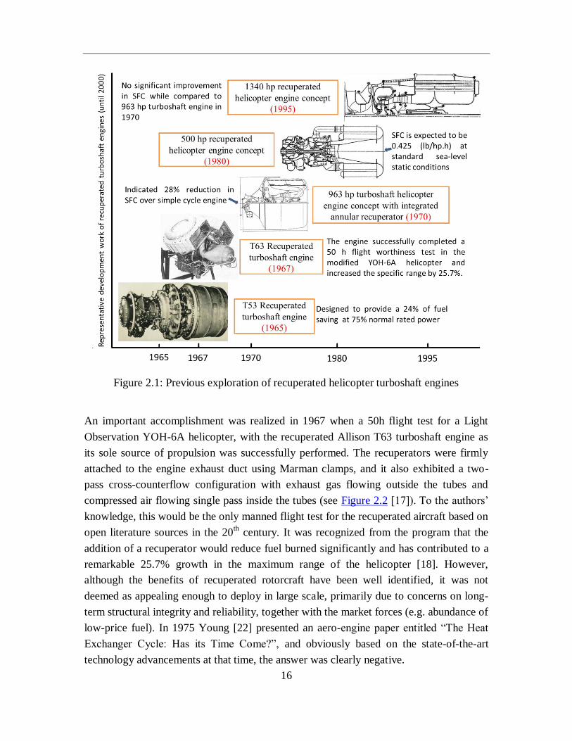
Figure 2.1: Previous exploration of recuperated helicopter turboshaft engines
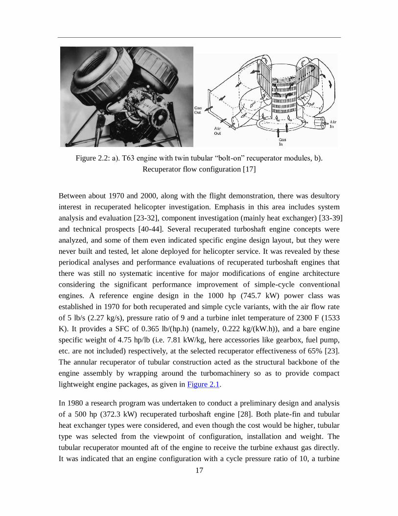
An important accomplishment was realized in 1967 when a 50h flight test for a Light
Observation YOH-6A helicopter, with the recuperated Allison T63 turboshaft engine as
its sole source of propulsion was successfully performed. The recuperators were firmly
attached to the engine exhaust duct using Marman clamps, and it also exhibited a two-
pass cross-counterflow configuration with exhaust gas flowing outside the tubes and
compressed air flowing single pass inside the tubes (see Figure 2.2 [17]). To the authors’
knowledge, this would be the only manned flight test for the recuperated aircraft based on
open literature sources in the 20th century. It was recognized from the program that the
addition of a recuperator would reduce fuel burned significantly and has contributed to a
remarkable 25.7% growth in the maximum range of the helicopter [18]. However,
although the benefits of recuperated rotorcraft have been well identified, it was not
deemed as appealing enough to deploy in large scale, primarily due to concerns on long-
term structural integrity and reliability, together with the market forces (e.g. abundance of
low-price fuel). In 1975 Young [22] presented an aero-engine paper entitled “The Heat
Exchanger Cycle: Has its Time Come?”, and obviously based on the state-of-the-art
technology advancements at that time, the answer was clearly negative.
17
Figure 2.2: a). T63 engine with twin tubular “bolt-on” recuperator modules, b).
Recuperator flow configuration [17]
Between about 1970 and 2000, along with the flight demonstration, there was desultory
interest in recuperated helicopter investigation. Emphasis in this area includes system
analysis and evaluation [23-32], component investigation (mainly heat exchanger) [33-39]
and technical prospects [40-44]. Several recuperated turboshaft engine concepts were
analyzed, and some of them even indicated specific engine design layout, but they were
never built and tested, let alone deployed for helicopter service. It was revealed by these
periodical analyses and performance evaluations of recuperated turboshaft engines that
there was still no systematic incentive for major modifications of engine architecture
considering the significant performance improvement of simple-cycle conventional
engines. A reference engine design in the 1000 hp (745.7 kW) power class was
established in 1970 for both recuperated and simple cycle variants, with the air flow rate
of 5 lb/s (2.27 kg/s), pressure ratio of 9 and a turbine inlet temperature of 2300 F (1533
K). It provides a SFC of 0.365 lb/(hp.h) (namely, 0.222 kg/(kW.h)), and a bare engine
specific weight of 4.75 hp/lb (i.e. 7.81 kW/kg, here accessories like gearbox, fuel pump,
etc. are not included) respectively, at the selected recuperator effectiveness of 65% [23].
The annular recuperator of tubular construction acted as the structural backbone of the
engine assembly by wrapping around the turbomachinery so as to provide compact
lightweight engine packages, as given in Figure 2.1.
In 1980 a research program was undertaken to conduct a preliminary design and analysis
of a 500 hp (372.3 kW) recuperated turboshaft engine [28]. Both plate-fin and tubular
heat exchanger types were considered, and even though the cost would be higher, tubular
type was selected from the viewpoint of configuration, installation and weight. The
tubular recuperator mounted aft of the engine to receive the turbine exhaust gas directly.
It was indicated that an engine configuration with a cycle pressure ratio of 10, a turbine
18
inlet temperature of 2300 F (1533 K), and a recuperator effectiveness of 70% was most
suitable for the 1980 environment. In 1987, projections were also made in Ref.[33] that
recuperated turboshaft propulsion engines would become a reality before the end of this
century considering the then current heat exchanger technology advancements. The
development and deployment of such aero-engines, initially for defence systems, seems
to be more likely a question to be resolved.
A reference reported in 1992 provided limited information about the AL-34-1
recuperated turboshaft engine in Russia, and the SFC of 0.348 lb/(hp.h) (i.e. 0.212
kg/(kW.h)) was achieved with a recuperator weight of 88 lb (40 kg) at altitude conditions
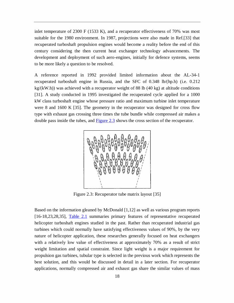
[31]. A study conducted in 1995 investigated the recuperated cycle applied for a 1000
kW class turboshaft engine whose pressure ratio and maximum turbine inlet temperature
were 8 and 1600 K [35]. The geometry in the recuperator was designed for cross flow
type with exhaust gas crossing three times the tube bundle while compressed air makes a
double pass inside the tubes, and Figure 2.3 shows the cross section of the recuperator.
Figure 2.3: Recuperator tube matrix layout [35]
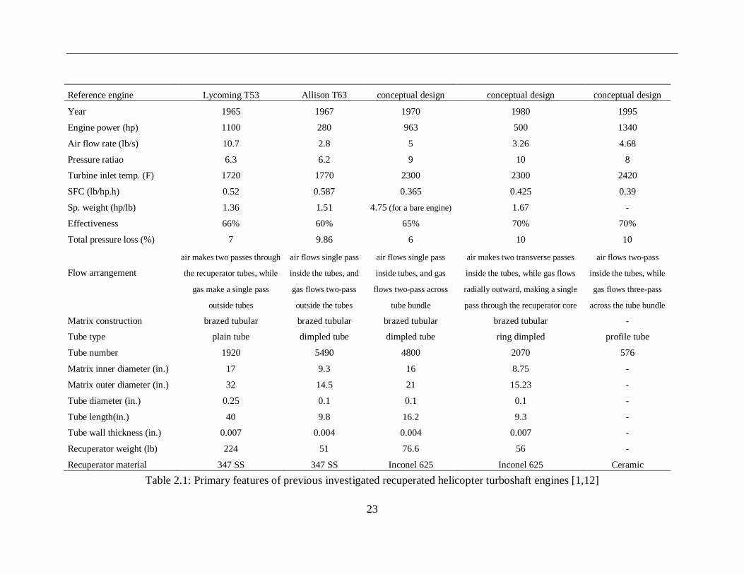
Based on the information gleaned by McDonald [1,12] as well as various program reports
[16-18,23,28,35], Table 2.1 summaries primary features of representative recuperated
helicopter turboshaft engines studied in the past. Rather than recuperated industrial gas
turbines which could normally have satisfying effectiveness values of 90%, by the very
nature of helicopter application, these researches generally focused on heat exchangers
with a relatively low value of effectiveness at approximately 70% as a result of strict
weight limitation and spatial constraint. Since light weight is a major requirement for
propulsion gas turbines, tubular type is selected in the previous work which represents the
best solution, and this would be discussed in detail in a later section. For recuperator
applications, normally compressed air and exhaust gas share the similar values of mass
19
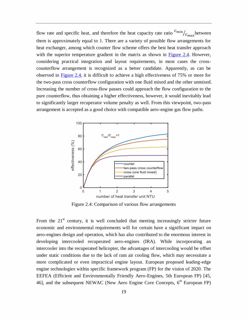
flow rate and specific heat, and therefore the heat capacity rate ratio 𝑐𝑚𝑖𝑛
𝑐𝑚𝑎𝑥⁄ between
them is approximately equal to 1. There are a variety of possible flow arrangements for
heat exchanger, among which counter flow scheme offers the best heat transfer approach
with the superior temperature gradient in the matrix as shown in Figure 2.4. However,
considering practical integration and layout requirements, in most cases the cross-
counterflow arrangement is recognized as a better candidate. Apparently, as can be
observed in Figure 2.4, it is difficult to achieve a high effectiveness of 75% or more for
the two-pass cross counterflow configuration with one fluid mixed and the other unmixed.
Increasing the number of cross-flow passes could approach the flow configuration to the
pure counterflow, thus obtaining a higher effectiveness, however, it would inevitably lead
to significantly larger recuperator volume penalty as well. From this viewpoint, two-pass
arrangement is accepted as a good choice with compatible aero-engine gas flow paths.
Figure 2.4: Comparison of various flow arrangements
From the 21st century, it is well concluded that meeting increasingly stricter future
economic and environmental requirements will for certain have a significant impact on
aero-engines design and operation, which has also contributed to the enormous interest in
developing intercooled recuperated aero-engines (IRA). While incorporating an
intercooler into the recuperated helicopter, the advantages of intercooling would be offset
under static conditions due to the lack of ram air cooling flow, which may necessitate a
more complicated or even impractical engine layout. European proposed leading-edge
engine technologies within specific framework program (FP) for the vision of 2020. The
EEFEA (Efficient and Environmentally Friendly Aero-Engines, 5th European FP) [45,
46], and the subsequent NEWAC (New Aero Engine Core Concepts, 6th European FP)
20
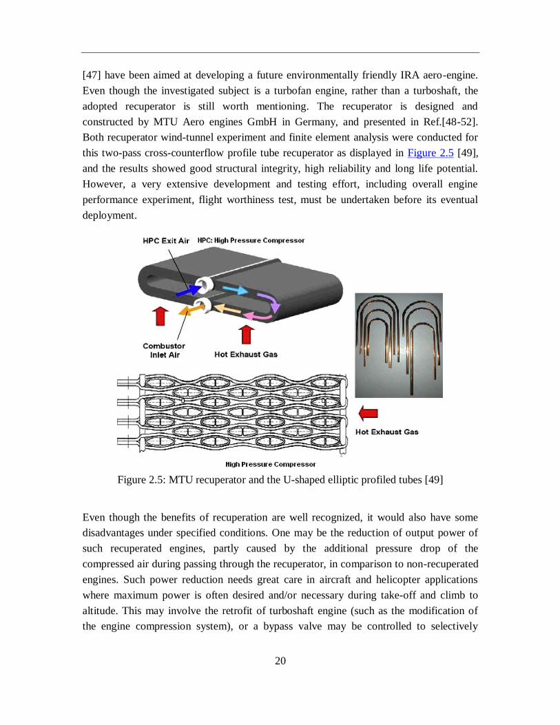
[47] have been aimed at developing a future environmentally friendly IRA aero-engine.
Even though the investigated subject is a turbofan engine, rather than a turboshaft, the
adopted recuperator is still worth mentioning. The recuperator is designed and
constructed by MTU Aero engines GmbH in Germany, and presented in Ref.[48-52].
Both recuperator wind-tunnel experiment and finite element analysis were conducted for
this two-pass cross-counterflow profile tube recuperator as displayed in Figure 2.5 [49],
and the results showed good structural integrity, high reliability and long life potential.
However, a very extensive development and testing effort, including overall engine
performance experiment, flight worthiness test, must be undertaken before its eventual
deployment.
Figure 2.5: MTU recuperator and the U-shaped elliptic profiled tubes [49]
Even though the benefits of recuperation are well recognized, it would also have some
disadvantages under specified conditions. One may be the reduction of output power of
such recuperated engines, partly caused by the additional pressure drop of the
compressed air during passing through the recuperator, in comparison to non-recuperated
engines. Such power reduction needs great care in aircraft and helicopter applications
where maximum power is often desired and/or necessary during take-off and climb to
altitude. This may involve the retrofit of turboshaft engine (such as the modification of
the engine compression system), or a bypass valve may be controlled to selectively
21
switch between recuperated and non-recuperated mode based on engine operating
conditions [20, 28, 53].
Another potential disadvantage is the additional bulk and weight of recuperator. In most
cases, turbine engines provide high power to weight ratio over reciprocating engines of
the same power rating, therefore they have found widely acceptance in aircraft
applications. The incorporation of a recuperator would to some extend weaken this
strength. The beneficial fuel saving may not compensate the additional recuperator
weight. The detailed trade-off evaluation were conducted at mission level in Ref.[54-56],
and it was suggested that the application of recuperator possesses great potential,
especially for long duration and large range mission, but it may not be necessarily
suitable for all types of helicopter missions.
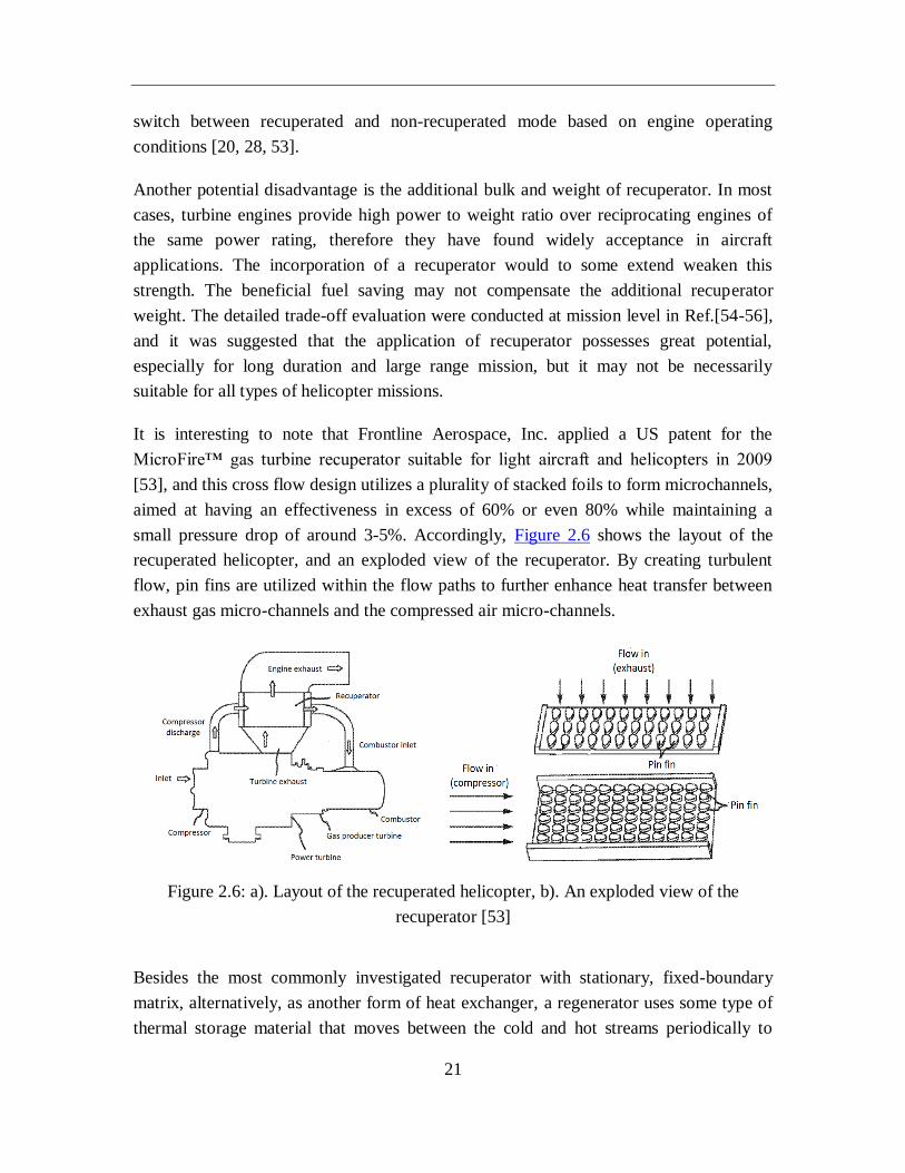
It is interesting to note that Frontline Aerospace, Inc. applied a US patent for the
MicroFire™ gas turbine recuperator suitable for light aircraft and helicopters in 2009
[53], and this cross flow design utilizes a plurality of stacked foils to form microchannels,
aimed at having an effectiveness in excess of 60% or even 80% while maintaining a
small pressure drop of around 3-5%. Accordingly, Figure 2.6 shows the layout of the
recuperated helicopter, and an exploded view of the recuperator. By creating turbulent
flow, pin fins are utilized within the flow paths to further enhance heat transfer between
exhaust gas micro-channels and the compressed air micro-channels.
Figure 2.6: a). Layout of the recuperated helicopter, b). An exploded view of the
recuperator [53]
Besides the most commonly investigated recuperator with stationary, fixed-boundary
matrix, alternatively, as another form of heat exchanger, a regenerator uses some type of
thermal storage material that moves between the cold and hot streams periodically to
22
transfer heat. A series of valuable development and testing efforts have been undertaken
by Lombardo et al. in the early 1960s using liquid mental as heat transport fluid for
applications to aircraft turboshaft engines incorporating regenerators, which demonstrates
the feasibility and performance of such a system in aircraft powerplants [57-60]. A
number of regenerative cycles for high efficiency gas turbines have been reported in
Ref.[61]. However, the negative characteristics of the regenerator in terms of durability
and seal leakage have continuously impeded its widespread application. The reduction of
seal leakage below about 7% has been achieved through the ongoing technological
development for rotary ceramic disk regenerators, but factors including complex
integration with the rotating machinery, along with the seal system and drive mechanism,
aggravate the cost concerns [13]. With magnesium alloy being selected as material, a
regenerator was designed and assessed by the CFD tool CFX in 2008 for a turboshaft
helicopter engine, and the obtained results indicated that the thermal efficiency could be
improved by 5% with 23% reduction in terms of SFC [62].
23
Reference engine Lycoming T53 Allison T63 conceptual design conceptual design conceptual design
Year 1965 1967 1970 1980 1995
Engine power (hp) 1100 280 963 500 1340
Air flow rate (lb/s) 10.7 2.8 5 3.26 4.68
Pressure ratiao 6.3 6.2 9 10 8
Turbine inlet temp. (F) 1720 1770 2300 2300 2420
SFC (lb/hp.h) 0.52 0.587 0.365 0.425 0.39
Sp. weight (hp/lb) 1.36 1.51 4.75 (for a bare engine) 1.67 -
Effectiveness 66% 60% 65% 70% 70%
Total pressure loss (%) 7 9.86 6 10 10
Flow arrangement
air makes two passes through
the recuperator tubes, while
gas make a single pass
outside tubes
air flows single pass
inside the tubes, and
gas flows two-pass
outside the tubes
air flows single pass
inside tubes, and gas
flows two-pass across
tube bundle
air makes two transverse passes
inside the tubes, while gas flows
radially outward, making a single
pass through the recuperator core
air flows two-pass
inside the tubes, while
gas flows three-pass
across the tube bundle
Matrix construction brazed tubular brazed tubular brazed tubular brazed tubular -
Tube type plain tube dimpled tube dimpled tube ring dimpled profile tube
Tube number 1920 5490 4800 2070 576
Matrix inner diameter (in.) 17 9.3 16 8.75 -
Matrix outer diameter (in.) 32 14.5 21 15.23 -
Tube diameter (in.) 0.25 0.1 0.1 0.1 -
Tube length(in.) 40 9.8 16.2 9.3 -
Tube wall thickness (in.) 0.007 0.004 0.004 0.007 -
Recuperator weight (lb) 224 51 76.6 56 -
Recuperator material 347 SS 347 SS Inconel 625 Inconel 625 Ceramic
Table 2.1: Primary features of previous investigated recuperated helicopter turboshaft engines [1,12]
24
2.1.2 Performance projection for turboshaft engines
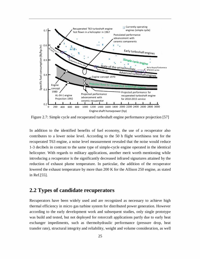
Over the past several decades, significant advancement has been achieved in turboshaft
engine performance over a wide power range, and Figure 2.7 shows the SFC tendency for
different technology strategies and engineering levels. It represents a follow-on to work
published by McDonald in 2008 [63] with updated information for the curve of state-of-
the-art technology on the basis of numerous operating engine data collected in Ref.[64],
and basically in the helicopter market, helicopters could be divided into light singles
(<500 kW), light twins (500-1500 kW), intermediate (1500-4000 kW), medium (4000-
7000 kW) and heavy-class (>7000 kW) by their shaft power [65,66]. Besides that, light
singles and twins class represent more than 60% of the civil market. Higher engine shaft
power generally represents larger geometric dimensions, which typically contributes to
better component efficiencies for turbine, compressor, combustor etc. Therefore, the SFC
shows a consistent decrease tendency with engine shaft power as depicted in Figure 2.7,
though these two parameters are indirectly relevant to each other. According to these
engine data, Rolls-Royce RTM 322 series show the best reported case with the lowest
SFC value of 0.424 lb/(hp.h) (i.e. 0.258 kg/(kW.h)) in 2400-2600 hp (1790-1939 kW)
engine power. McDonald also made an estimation for the SFC band of recuperated
turboshaft engines, based on scatter of data collected from previous introduced cases of
recuperated engines, and then extrapolate to higher power levels. He estimated the
performance of recuperated turboshaft engine for service in 2010-2015 with an appealing
SFC of 0.34 lb/(hp.h) (i.e. 0.207 kg/(kW.h)), but this is just tentative, and no such engine
has been reported.
Apparently, despite the significant improvement in simple cycle engines over these
decades, it reveals a tremendous gap in terms of SFC when compared to recuperated
turboshaft engines. As can be noted, it would be a formidable challenge to develop a
recuperated turboshaft for the engine power range below 1500 hp (1118.5 kW), achieving
an ambitious SFC of less than 0.3 lb/(hp.h) (i.e. 0.182 kg/(kW.h)). The continuous
performance promotion of simple-cycle turboshaft engines, especially in the era of low
fuel price, together with the weight, volume and reliability concerns for high temperature
heat exchangers, which have been improving in recent years, have delayed the further
application of recuperated engines for helicopter propulsion.
25
Figure 2.7: Simple cycle and recuperated turboshaft engine performance projection [57]
In addition to the identified benefits of fuel economy, the use of a recuperator also
contributes to a lower noise level. According to the 50 h flight worthiness test for the
recuperated T63 engine, a noise level measurement revealed that the noise would reduce
1-3 decibels in contrast to the same type of simple-cycle engine operated in the identical
helicopter. With regards to military applications, another merit worth mentioning while
introducing a recuperator is the significantly decreased infrared signatures attained by the
reduction of exhaust plume temperature. In particular, the addition of the recuperator
lowered the exhaust temperature by more than 200 K for the Allison 250 engine, as stated
in Ref.[55].
2.2 Types of candidate recuperators
Recuperators have been widely used and are recognized as necessary to achieve high
thermal efficiency in micro gas turbine system for distributed power generation. However
according to the early development work and subsequent studies, only single prototype
was build and tested, but not deployed for rotorcraft applications partly due to early heat
exchanger impediments, such as thermohydraulic performance (pressure drop, heat
transfer rate), structural integrity and reliability, weight and volume consideration, as well
26
as the lack of market forces (e.g. simple-cycle engine performance improvement,
abundance of low-cost fuel). Currently, there is a renewed interest in adopting
recuperators to meet the requirement for highly efficient, environmentally friendly aero-
engines in the context of the increasingly stringent emissions legislation and serious
energy challenge. In this section, promising high temperature heat exchanger candidates
embodying on-going technology advancements are evaluated for the sake of finding
recuperators potentially applicable to aeroengines, thus enhancing the integrated
performance and operational capabilities of rotorcraft powerplants. Based on the heat
transfer surface geometry, heat exchangers have been used in the gas turbine systems
acting as recuperators could be representatively classified into three different types, i.e.,
plate-fin, primary surface and tubular.
2.2.1 Plate-fin geometry
Plate-fin heat exchangers mainly consist of a series of fin surfaces together with flat
separators knows as parting sheets. The main attribute of plate-fin surface is that the
introduced fins work as secondary heat transfer surface and in the meanwhile provide
mechanical support against internal pressure differentials between layers. The plate-fin
type has been widely used in decades for a range of gas turbine applications [67-70], and
the manufacturing technologies are quite mature. Various fin designs have been
developed including plain, offset strip, wavy etc., and plenty of flow and heat transfer
characteristics data regarding these fin channels were reported on the basis of
experimental work [71] which provide a solid foundation for the recuperator design.
However there are some significant limitations for plate-fin designs including limited
material flexibility, long braze cycle, complex assembly and high capital cost etc. [72].
Most importantly, the bulky weight of matrix has essentially eliminated them for further
consideration in recuperated helicopter turboshaft engines.
2.2.2 Primary-surface geometry
The primary surface recuperator comprises corrugated thin sheets stacked together with
gas (hot) stream and air (cold) stream flowing through alternate layers, and the main
characteristic of this kind of construction is that heat transfer takes place directly through
these thin plates without secondary surface fin efficiency effects. With regards to
tightness, sealing between cold/hot stream passages could be accomplished by welding
rather than the time consuming high-temperature furnace brazing operation required for
27
plate-fin types. The primary surface recuperator is suitable for relatively low pressure (LP)
ratio engine applications, like many helicopter turboshafts engines. In addition, it is not
feasible to incorporate this type of recuperator into high pressure (HP) ratio engines due
to the lack of supporting structural elements between flow passages. Fabricated in cube-
shaped or annular configurations, several applications of primary surface recuperators in
gas turbine systems have been reported previously [73-76], which give good performance
and demonstrate a high degree of structural integrity. Furthermore, the manufacturing of
primary surface recuperators is amenable to high-volume manufacturing processes, which
leads to lower cost. For these reasons, it would be therefore a promising candidate for
further consideration.
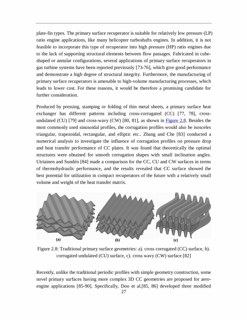
Produced by pressing, stamping or folding of thin metal sheets, a primary surface heat
exchanger has different patterns including cross-corrugated (CC) [77, 78], cross-
undulated (CU) [79] and cross-wavy (CW) [80, 81], as shown in Figure 2.8. Besides the
most commonly used sinusoidal profiles, the corrugation profiles would also be isosceles
triangular, trapezoidal, rectangular, and elliptic etc.. Zhang and Che [83] conducted a
numerical analysis to investigate the influence of corrugation profiles on pressure drop
and heat transfer performance of CC plates. It was found that theoretically the optimal
structures were obtained for smooth corrugation shapes with small inclination angles.
Utriainen and Sundén [84] made a comparison for the CC, CU and CW surfaces in terms
of thermohydraulic performance, and the results revealed that CC surface showed the
best potential for utilization in compact recuperators of the future with a relatively small
volume and weight of the heat transfer matrix.
Figure 2.8: Traditional primary surface geometries: a). cross corrugated (CC) surface, b).
corrugated undulated (CU) surface, c). cross wavy (CW) surface [82]
Recently, unlike the traditional periodic profiles with simple geometry construction, some
novel primary surfaces having more complex 3D CC geometries are proposed for aero-
engine applications [85-90]. Specifically, Doo et al.[85, 86] developed three modified
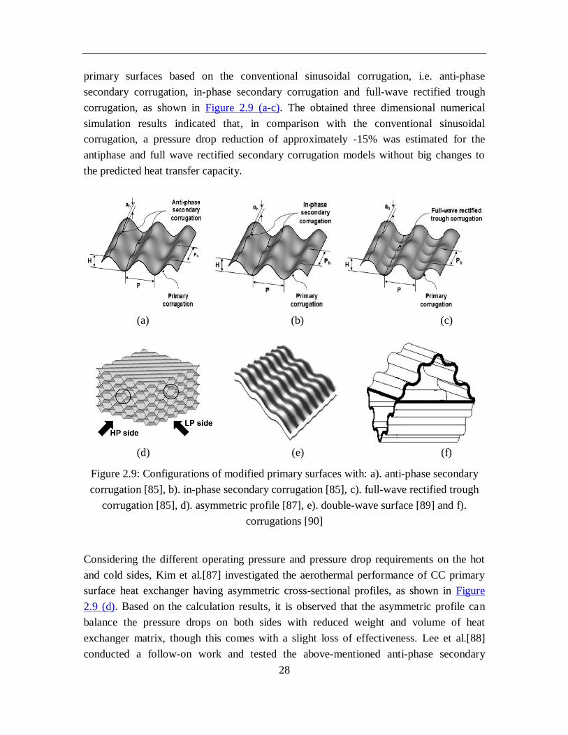
28
primary surfaces based on the conventional sinusoidal corrugation, i.e. anti-phase
secondary corrugation, in-phase secondary corrugation and full-wave rectified trough
corrugation, as shown in Figure 2.9 (a-c). The obtained three dimensional numerical
simulation results indicated that, in comparison with the conventional sinusoidal
corrugation, a pressure drop reduction of approximately -15% was estimated for the
antiphase and full wave rectified secondary corrugation models without big changes to
the predicted heat transfer capacity.
(a) (b) (c)
(d) (e) (f)
Figure 2.9: Configurations of modified primary surfaces with: a). anti-phase secondary
corrugation [85], b). in-phase secondary corrugation [85], c). full-wave rectified trough
corrugation [85], d). asymmetric profile [87], e). double-wave surface [89] and f).
corrugations [90]
Considering the different operating pressure and pressure drop requirements on the hot
and cold sides, Kim et al.[87] investigated the aerothermal performance of CC primary
surface heat exchanger having asymmetric cross-sectional profiles, as shown in Figure
2.9 (d). Based on the calculation results, it is observed that the asymmetric profile can
balance the pressure drops on both sides with reduced weight and volume of heat
exchanger matrix, though this comes with a slight loss of effectiveness. Lee et al.[88]
conducted a follow-on work and tested the above-mentioned anti-phase secondary
29
corrugation and asymmetric profile using a Transient Liquid Crystal (TLC) heat transfer
measurement technique. It is concluded that to minimize the weight of the heat
exchangers in aero-engine application, the asymmetric geometries are more favorable
with appealing values of area and volume goodness factors. Kim and Baik et al.[89]
performed an experimental study on a cross-flow air-cooled heat exchangers with newly
double-wave CC primary surface, as depicted in Figure 2.9 (e). From the tests, double-
wave prototype heat exchanger shows approximately 50% enhanced heat transfer
performance at the cost of 30% additional pressure drop while compared to single-wave
structure. Liu et al.[90] analyzed fluid flow and heat transfer characteristics of
microchannel in a CC primary surface recuperators with corrugations, as shown in Figure
2.9 (f). According to the obtained CFD calculation results, the heat transfer performance
in surface with corrugation would increase 10% in contrast to that without corrugation.
2.2.3 Tubular geometry
Tubular recuperators are made up of numerous tubes within an outer shell, and they have
favorable pressure containing capability. According to the early development activities in
the 1960-1970 time frame and subsequent intermittent researches by the end of 20th
century, tubular type was normally considered as the first choice for recuperated aero-
turboshaft applications, primarily due to its high reliability based on technologies
prevailing in that era, as well as the paramount requirement for light weight by the very
nature of aero-engine applications. In order to develop lightweight tubular recuperators,
small tube diameters and compact geometries are utilized which necessitates brazing the
assembly together [91]. It could be essentially concluded that technology has not
advanced much in dimpled tube recuperator technology which would contribute to
significant reduction in recuperator size and weight, while comparing the initially
proposed recuperated T63 turboshaft engine in 1967 with the 500 hp (372.3 kW)
recuperated turboshaft engine concept in 1980. Highly compact tubular heat exchangers
with tube diameters as small as 1 mm were fabricated in early 1990s with automated
manufacturing processes [92], and the high cost and fabrication complexity limited their
use for most applications.
Compared to rectangular cross sectional geometry, a circular tube matrix has typically
smaller surface area for a given flow area with lower heat transfer coefficient. Therefore
focus is given on using oval tubes to obviate these performance disadvantages. Previous
studies indicated that profile tubes (also known as oval tubes) arranged in bundles
showed superior fluid flow and heat transfer characteristics, and therefore adopted in
early exploration of recuperated helicopter turboshaft engines [23,28,35]. A particularly
30
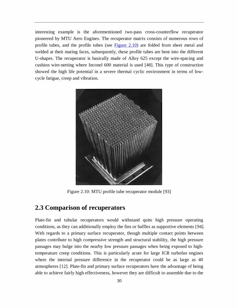
interesting example is the aforementioned two-pass cross-counterflow recuperator
pioneered by MTU Aero Engines. The recuperator matrix consists of numerous rows of
profile tubes, and the profile tubes (see Figure 2.10) are folded from sheet metal and
welded at their mating faces, subsequently, these profile tubes are bent into the different
U-shapes. The recuperator is basically made of Alloy 625 except the wire-spacing and
cushion wire-netting where Inconel 600 material is used [48]. This type of construction
showed the high life potential in a severe thermal cyclic environment in terms of low-
cycle fatigue, creep and vibration.
Figure 2.10: MTU profile tube recuperator module [93]
2.3 Comparison of recuperators
Plate-fin and tubular recuperators would withstand quite high pressure operating
conditions, as they can additionally employ the fins or baffles as supportive elements [94].
With regards to a primary surface recuperator, though multiple contact points between
plates contribute to high compressive strength and structural stability, the high pressure
passages may bulge into the nearby low pressure passages when being exposed to high-
temperature creep conditions. This is particularly acute for large ICR turbofan engines
where the internal pressure difference in the recuperator could be as large as 40
atmospheres [12]. Plate-fin and primary surface recuperators have the advantage of being
able to achieve fairly high effectiveness, however they are difficult to assemble due to the
31
large number of plates. Besides that, highly stressed welding or brazing operations for the
sake of sealing would bring about the risks of leakage or failure. Because of the bulky
weight of plate-fin recuperators, they are excluded from recuperated helicopter
propulsion. Ward et al. [95] pointed out that to meet the given thermal duty, the needed
unit volume for plate-fin and tubular recuperators are respectively 2.8 and 11.8 times that
of primary surface types.
The required recuperator operating characteristics for aero-turboshaft engines are: high
mass flow rate, large heat transfer effectiveness, moderate pressure containing capability,
high temperature resistance, and small pressure drop. Additional important performance
requirements include light weight, compact size and high reliability. Since the additional
weight of the recuperator could act as a direct penalty in the overall performance of the
rotorcraft and therefore should be strictly controlled, based on previous researches, in the
past only tubular recuperators were deployed where moderate loss of heat transfer
effectiveness was tolerated, and they exhibited a relatively low effectiveness of 60-70%.
The current evolution tendency of heat transfer enhancement technology is towards
smaller hydraulic diameters, thus increasing compactness [94]. Mehendale et al. [96]
reviewed the fluid flow and heat transfer characteristics in channels with hydraulic
diameters in the range of 1 um to 6 mm. Utriainen et al. [97] compared the thermal and
hydraulic performance of various primary surface recuperators (CC, CW, CU
configurations), and the hydraulic diameter is chosen to be as small as 1.54 mm. They all
show superior performance when compared to the available examples of operating
recuperators, and their volumes are approximately 30% less than expectation based on
the portrayal of data collected from actual cases. The limits are, flow maldistribution,
longitudinal conduction effects and fouling when used as a recuperator for heat transfer
between exhaust gas and compressed air in the gas turbine system. Doo et al. [98]
conducted a quantitative assessment using CFD simulation to study the longitudinal heat
conduction effect on the traditional CC primary surface heat exchanger. A maximum
performance degradation of 8.4% is predicted in their numerical studies.
Technology advancements have been made in recent years in the field of high
temperature heat exchanger and new surface geometries have emerged, especially for
primary surface types. With proven structural integrity, compact tubular recuperator with
small tube diameters (or even micro-channels), and novel primary surface recuperator
may be the appropriate choices for future recuperated rotorcraft propulsion development,
on the condition that moderate fabrication cost is expected when manufactured in large
production quantities.
32
2.4 Material selection and manufacturing technology
Normally due to cost considerations, most recuperators utilize existing metallic materials,
347 stainless steel (347 SS) in particular, and Inconel 625 for higher temperature
limitation (as also presented in Table 2.2). In order to meet the projected targets for
environmentally friendly future aero-engines, the potential of novel materials particularly
ceramic recuperators in the gas turbine systems is well recognized. The operating
temperature of recuperators is essentially limited by the resistance of the material to
corrosion, oxidation and creep deformation. The severe thermal cycling environment
(especially during take-off, landing) inherent to aero-engines would be posed as a major
threat for the long-term integrity (leak-tightness) and reliability of recuperators.
Oak Ridge National Laboratory (ORNL) has made a continuous effort to evaluate
candidate alloys, with primary focus on microturbine market [99-103]. Aquaro and Pieve
[104] also provide an overview of metallic recuperators for high temperature
requirements, as well as similar work done by McDonald [93] and Matthews et
al.[105,106]. Based on their research, several commonly considered candidate metallic
recuperator materials are summarized in Table 2.2 in terms of material cost (using 347 SS
as a baseline), maximal metal temperature and density. According to laboratory testing,
alloys with better creep-rupture resistance include Haynes 120, Haynes 230 and modified
Alloy 803. Besides that, Haynes 214 and Alloy 625 exhibited much better creep strength.
347 SS is widely used in recuperator industry with a fairly low material cost, but it has a
temperature limit of 675 ℃ (948 K) due to the accelerated corrosion by water vapor
contained in the exhaust gas. For higher temperature service, super alloys with a larger
nickel content are of interest. Alloy 625 and Haynes 120 show excellent corrosion
resistance in foil form. Alloy 625 would be the very high performance alternative for use
at temperature up to 800 ℃ (1073 K), and has the most cost-effective improvements
contrast to 347 SS, though at a material cost factor of 4-5. Besides the extensively
demonstrated recuperator materials 347 SS and Alloy 625, with respect to chemical
composition and cost, modified Alloy 803 and Haynes 120 could extend their application
to about 750 ℃ (1023 K), having approximately twice the creep resistance of 347 SS
with a reasonable cost of 3-3.5 times. Therefore, they are recognized as possibly the best
alternatives to 347 SS for higher temperature. Even though Haynes 230 and 214 possess
much larger temperature capability for using to 850 ℃ (1123 K) or even higher, the
substantially greater material cost essentially eliminates their widespread application in
recuperator industry.
33
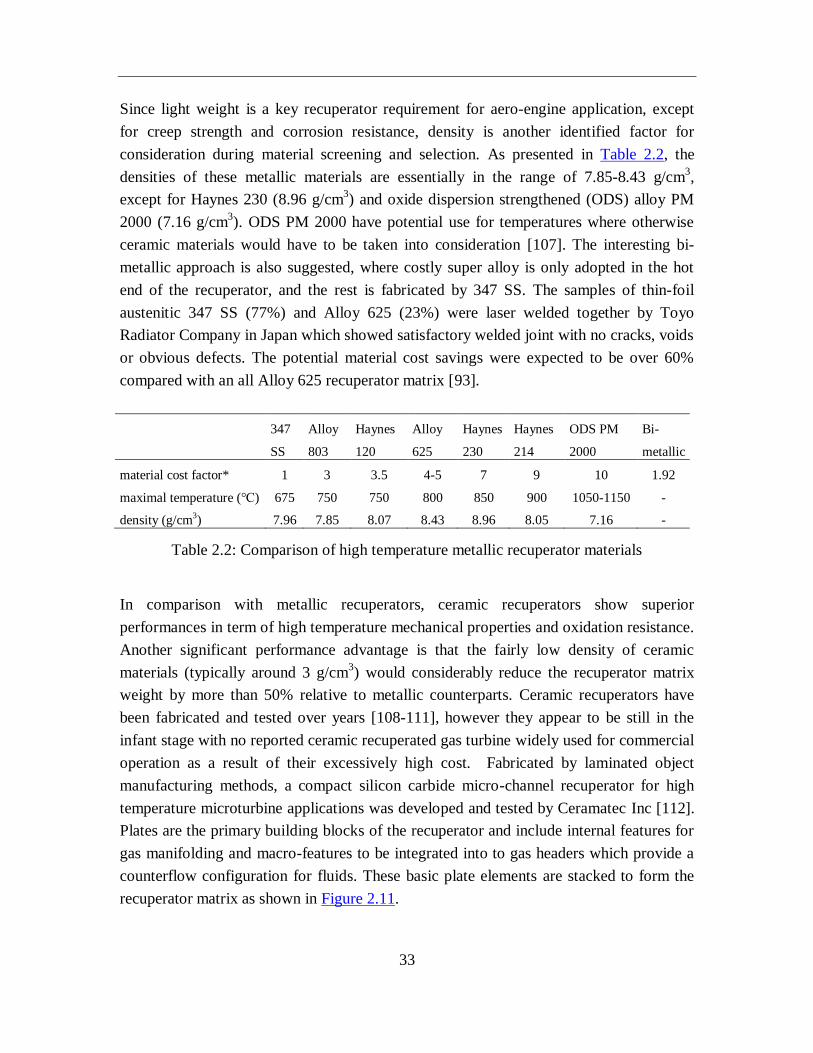
Since light weight is a key recuperator requirement for aero-engine application, except
for creep strength and corrosion resistance, density is another identified factor for
consideration during material screening and selection. As presented in Table 2.2, the
densities of these metallic materials are essentially in the range of 7.85-8.43 g/cm3,
except for Haynes 230 (8.96 g/cm3) and oxide dispersion strengthened (ODS) alloy PM
2000 (7.16 g/cm3). ODS PM 2000 have potential use for temperatures where otherwise
ceramic materials would have to be taken into consideration [107]. The interesting bi-
metallic approach is also suggested, where costly super alloy is only adopted in the hot
end of the recuperator, and the rest is fabricated by 347 SS. The samples of thin-foil
austenitic 347 SS (77%) and Alloy 625 (23%) were laser welded together by Toyo
Radiator Company in Japan which showed satisfactory welded joint with no cracks, voids
or obvious defects. The potential material cost savings were expected to be over 60%
compared with an all Alloy 625 recuperator matrix [93].
347
SS
Alloy
803
Haynes
120
Alloy
625
Haynes
230
Haynes
214
ODS PM
2000
Bi-
metallic
material cost factor* 1 3 3.5 4-5 7 9 10 1.92
maximal temperature (℃) 675 750 750 800 850 900 1050-1150 -
density (g/cm3) 7.96 7.85 8.07 8.43 8.96 8.05 7.16 -
Table 2.2: Comparison of high temperature metallic recuperator materials
In comparison with metallic recuperators, ceramic recuperators show superior
performances in term of high temperature mechanical properties and oxidation resistance.
Another significant performance advantage is that the fairly low density of ceramic
materials (typically around 3 g/cm3) would considerably reduce the recuperator matrix
weight by more than 50% relative to metallic counterparts. Ceramic recuperators have
been fabricated and tested over years [108-111], however they appear to be still in the
infant stage with no reported ceramic recuperated gas turbine widely used for commercial
operation as a result of their excessively high cost. Fabricated by laminated object
manufacturing methods, a compact silicon carbide micro-channel recuperator for high
temperature microturbine applications was developed and tested by Ceramatec Inc [112].
Plates are the primary building blocks of the recuperator and include internal features for
gas manifolding and macro-features to be integrated into to gas headers which provide a
counterflow configuration for fluids. These basic plate elements are stacked to form the
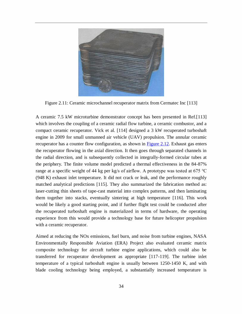
recuperator matrix as shown in Figure 2.11.
34
Figure 2.11: Ceramic microchannel recuperator matrix from Cermatec Inc [113]
A ceramic 7.5 kW microturbine demonstrator concept has been presented in Ref.[113]
which involves the coupling of a ceramic radial flow turbine, a ceramic combustor, and a
compact ceramic recuperator. Vick et al. [114] designed a 3 kW recuperated turboshaft
engine in 2009 for small unmanned air vehicle (UAV) propulsion. The annular ceramic
recuperator has a counter flow configuration, as shown in Figure 2.12. Exhaust gas enters
the recuperator flowing in the axial direction. It then goes through separated channels in
the radial direction, and is subsequently collected in integrally-formed circular tubes at
the periphery. The finite volume model predicted a thermal effectiveness in the 84-87%
range at a specific weight of 44 kg per kg/s of airflow. A prototype was tested at 675 ℃
(948 K) exhaust inlet temperature. It did not crack or leak, and the performance roughly
matched analytical predictions [115]. They also summarized the fabrication method as:
laser-cutting thin sheets of tape-cast material into complex patterns, and then laminating
them together into stacks, eventually sintering at high temperature [116]. This work
would be likely a good starting point, and if further flight test could be conducted after
the recuperated turboshaft engine is materialized in terms of hardware, the operating
experience from this would provide a technology base for future helicopter propulsion
with a ceramic recuperator.
Aimed at reducing the NOx emissions, fuel burn, and noise from turbine engines, NASA
Environmentally Responsible Aviation (ERA) Project also evaluated ceramic matrix
composite technology for aircraft turbine engine applications, which could also be
transferred for recuperator development as appropriate [117-119]. The turbine inlet
temperature of a typical turboshaft engine is usually between 1250-1450 K, and with
blade cooling technology being employed, a substantially increased temperature is
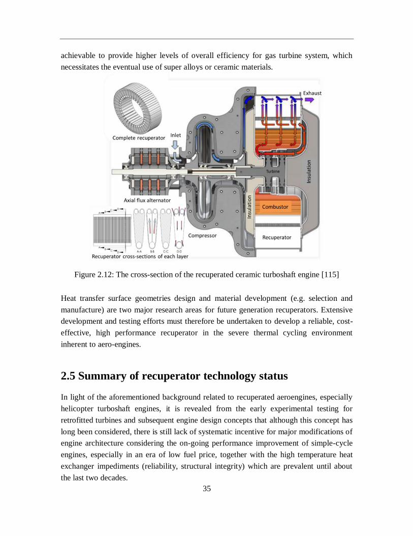
35
achievable to provide higher levels of overall efficiency for gas turbine system, which
necessitates the eventual use of super alloys or ceramic materials.
Figure 2.12: The cross-section of the recuperated ceramic turboshaft engine [115]
Heat transfer surface geometries design and material development (e.g. selection and
manufacture) are two major research areas for future generation recuperators. Extensive
development and testing efforts must therefore be undertaken to develop a reliable, cost-
effective, high performance recuperator in the severe thermal cycling environment
inherent to aero-engines.
2.5 Summary of recuperator technology status
In light of the aforementioned background related to recuperated aeroengines, especially
helicopter turboshaft engines, it is revealed from the early experimental testing for
retrofitted turbines and subsequent engine design concepts that although this concept has
long been considered, there is still lack of systematic incentive for major modifications of
engine architecture considering the on-going performance improvement of simple-cycle
engines, especially in an era of low fuel price, together with the high temperature heat
exchanger impediments (reliability, structural integrity) which are prevalent until about
the last two decades.
36
After evaluating the relevance of accumulated experience derived from previous
development work, three promising high temperature heat exchanger candidates, i.e.
tubular, primary surface and plate fin, are assessed in the light of state-of-the-art
technology advancements, aimed at finding heat exchangers potentially applicable to
rotorcraft recuperators. Furthermore, emphasis has also been placed on material selection
and manufacturing technology. It is concluded that for industrial and vehicular gas
turbine recuperators, since minimizing the recuperator weight is not paramount, plate-fin
geometries are favorable, particularly from the viewpoint of cost. However their bulky
weight actually eliminate them for further consideration in recuperated helicopter
turboshaft engines. Primary surface recuperators would likely be the appropriate choice
for future recuperator development, implementing novel 3D CC geometries with superior
heat transfer characteristics. Tubular types have been adopted in aero-turboshaft
applications ever since the initial stage of development in 1960s albeit their relatively low
effectiveness, as they have high reliability based on technologies prevailing in that era.
An additional important factor is that, they represent the best solution, essentially based
on weight consideration. Traditional profile tubes arranged in bundles are preferred for
further development. Smaller hydraulic diameters, thus increasing compactness may
contribute to light weight and small volume of the recuperator matrix, but flow
maldistribution, longitudinal conduction effects and fouling need attention.
Operating in the high temperature and severe thermal cycling environment, super alloys
and ceramic materials are suggested, but at a substantially greater projected cost relative
to the commercially used 347 SS. Modified Alloy 803 and Haynes 120 seem to be the
best alternatives up to 750 ℃ (1382 F) with respect to cost and creep-strength. The fairly
low density of ceramic materials contributes to a significant weight reduction in
recuperator matrix contrast to metallic counterparts. The advancement in heat exchanger
technologies in the fields of material science, mechanical design etc., together with the
urgent socio-economic considerations (e.g. strict emissions legislation, reduced fuel
consumption requirement) and/or specific needs for military applications (lower infrared
signature, increased flight range) necessitate more complicated aero-engine architectures
for the next generation and highlight the helicopter turboshaft concept embodying a
recuperator. An interesting technical strategy would be likely to firstly develop a quite
small ceramic recuperated turboshaft engine for UAV applications, with the accumulated
experience on bench experiment and flight testing, it could essentially provide a sound
technology base for advancing to small or medium class of recuperated helicopter
turboshaft engines for military service.
37
3. Performance evaluation of recuperated
rotorcraft powerplants
Through the recuperation process of exhaust waste heat utilization, the implementation of
recuperators for gas turbine systems has been proved to be a significant technical route to
meet the current challenges of reduced emissions and improved specific fuel
consumption (SFC) to develop highly efficient, environmentally friendly aero-engines.
This is particularly attractive for today’s rotorcraft powerplant, since one of its main
performance disadvantages is the increased SFC during part load, where the majority of
its mission time would be spent.
In this section, a computationally efficient multidisciplinary simulation framework is
proposed and implemented to analyze the influence of recuperator on the whole rotorcraft
powerplant system for further development of future recuperated aircrafts. The rotorcraft
powerplant configuration selected in this work is a generic helicopter, which is similar to
a typical multi-purpose utility helicopter Bo105, equipped with two Allison 250-C20B
turboshaft engine variants. The overall methodology comprises a series of individual
modeling theories in terms of helicopter flight dynamics, gas turbine engine performance,
etc. which are elaborated separately in detail. The research addressed within this work
could provide a solid foundation for the multidisciplinary design and optimization of
future recuperated rotorcraft powerplants.
3.1 Trade-off between improved fuel economy and
parasitic recuperator weight
As one of the main devices for many industrial gas turbines and microturbines,
recuperator is widely adopted with good performance and proven structural integrity.
However, there are several identified factors that mitigated its wide use in aircraft gas
turbine engines as elaborated in Chapter 2, including lack of market forces (low fuel
price, continuous performance advancements of simple-cycle engines) and high
temperature heat exchanger technology readiness (particularly until about the last two
decades). Furthermore, the recuperator volume and weight also need to be strictly
controlled due to stringent constraints on the carrying capability and limited space of the
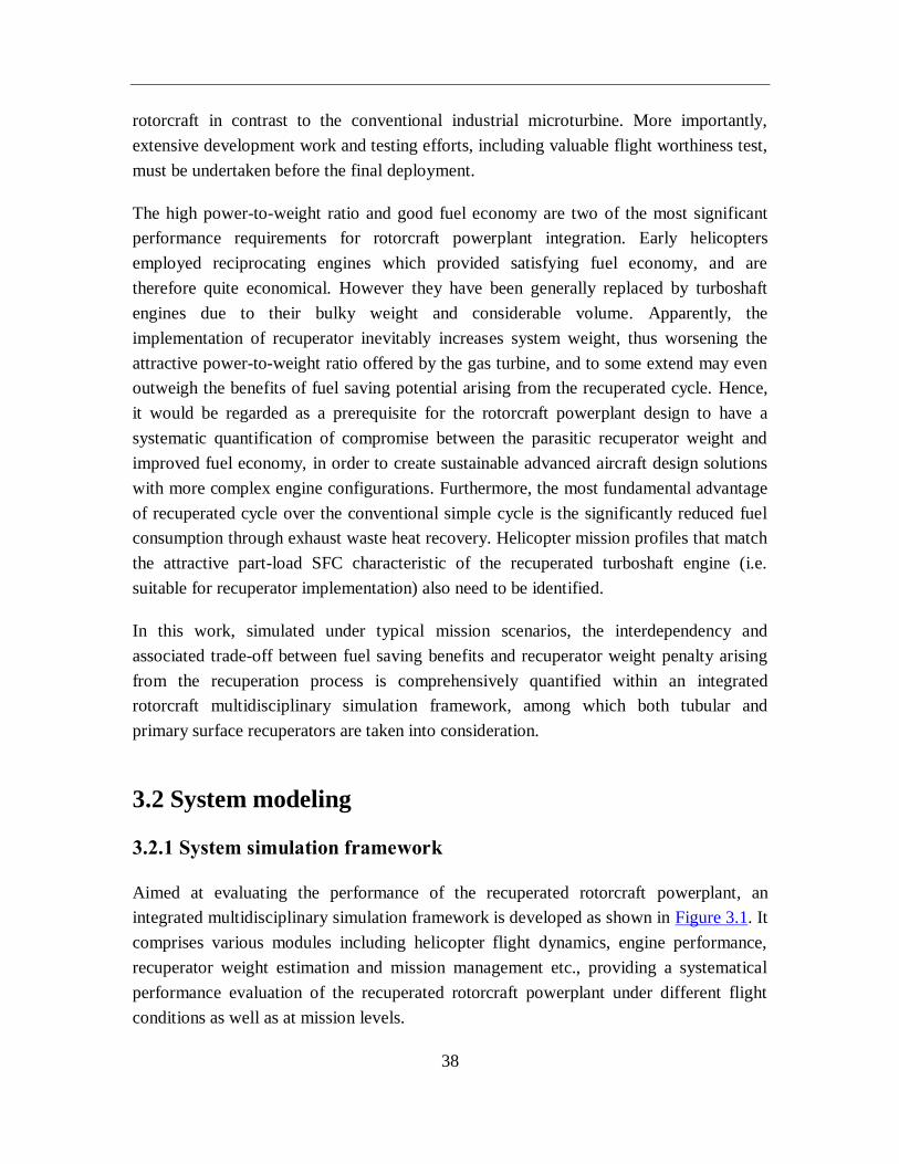
38
rotorcraft in contrast to the conventional industrial microturbine. More importantly,
extensive development work and testing efforts, including valuable flight worthiness test,
must be undertaken before the final deployment.
The high power-to-weight ratio and good fuel economy are two of the most significant
performance requirements for rotorcraft powerplant integration. Early helicopters
employed reciprocating engines which provided satisfying fuel economy, and are
therefore quite economical. However they have been generally replaced by turboshaft
engines due to their bulky weight and considerable volume. Apparently, the
implementation of recuperator inevitably increases system weight, thus worsening the
attractive power-to-weight ratio offered by the gas turbine, and to some extend may even
outweigh the benefits of fuel saving potential arising from the recuperated cycle. Hence,
it would be regarded as a prerequisite for the rotorcraft powerplant design to have a
systematic quantification of compromise between the parasitic recuperator weight and
improved fuel economy, in order to create sustainable advanced aircraft design solutions
with more complex engine configurations. Furthermore, the most fundamental advantage
of recuperated cycle over the conventional simple cycle is the significantly reduced fuel
consumption through exhaust waste heat recovery. Helicopter mission profiles that match
the attractive part-load SFC characteristic of the recuperated turboshaft engine (i.e.
suitable for recuperator implementation) also need to be identified.
In this work, simulated under typical mission scenarios, the interdependency and
associated trade-off between fuel saving benefits and recuperator weight penalty arising
from the recuperation process is comprehensively quantified within an integrated
rotorcraft multidisciplinary simulation framework, among which both tubular and
primary surface recuperators are taken into consideration.
3.2 System modeling
3.2.1 System simulation framework
Aimed at evaluating the performance of the recuperated rotorcraft powerplant, an
integrated multidisciplinary simulation framework is developed as shown in Figure 3.1. It
comprises various modules including helicopter flight dynamics, engine performance,
recuperator weight estimation and mission management etc., providing a systematical
performance evaluation of the recuperated rotorcraft powerplant under different flight
conditions as well as at mission levels.
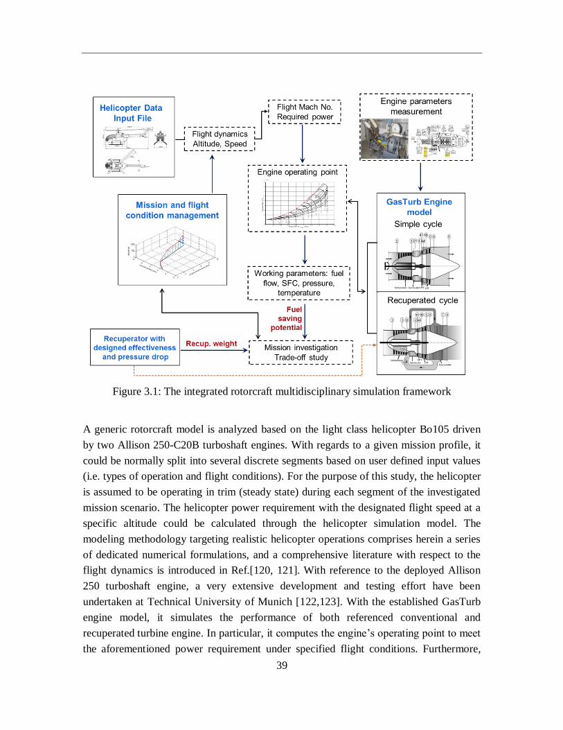
39
Figure 3.1: The integrated rotorcraft multidisciplinary simulation framework
A generic rotorcraft model is analyzed based on the light class helicopter Bo105 driven
by two Allison 250-C20B turboshaft engines. With regards to a given mission profile, it
could be normally split into several discrete segments based on user defined input values
(i.e. types of operation and flight conditions). For the purpose of this study, the helicopter
is assumed to be operating in trim (steady state) during each segment of the investigated
mission scenario. The helicopter power requirement with the designated flight speed at a
specific altitude could be calculated through the helicopter simulation model. The
modeling methodology targeting realistic helicopter operations comprises herein a series
of dedicated numerical formulations, and a comprehensive literature with respect to the
flight dynamics is introduced in Ref.[120, 121]. With reference to the deployed Allison
250 turboshaft engine, a very extensive development and testing effort have been
undertaken at Technical University of Munich [122,123]. With the established GasTurb
engine model, it simulates the performance of both referenced conventional and
recuperated turbine engine. In particular, it computes the engine’s operating point to meet
the aforementioned power requirement under specified flight conditions. Furthermore,
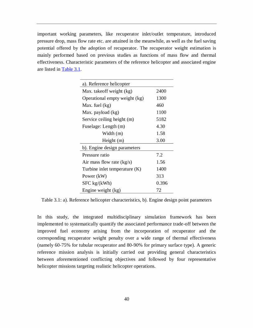
40
important working parameters, like recuperator inlet/outlet temperature, introduced
pressure drop, mass flow rate etc. are attained in the meanwhile, as well as the fuel saving
potential offered by the adoption of recuperator. The recuperator weight estimation is
mainly performed based on previous studies as functions of mass flow and thermal
effectiveness. Characteristic parameters of the reference helicopter and associated engine
are listed in Table 3.1.
a). Reference helicopter
Max. takeoff weight (kg) 2400
Operational empty weight (kg) 1300
Max. fuel (kg) 460
Max. payload (kg) 1100
Service ceiling height (m) 5182
Fuselage: Length (m) 4.30
Width (m) 1.58
Height (m) 3.00
b). Engine design parameters
Pressure ratio 7.2
Air mass flow rate (kg/s) 1.56
Turbine inlet temperature (K) 1400
Power (kW) 313
SFC kg/(kWh) 0.396
Engine weight (kg) 72
Table 3.1: a). Reference helicopter characteristics, b). Engine design point parameters
In this study, the integrated multidisciplinary simulation framework has been
implemented to systematically quantify the associated performance trade-off between the
improved fuel economy arising from the incorporation of recuperator and the
corresponding recuperator weight penalty over a wide range of thermal effectiveness
(namely 60-75% for tubular recuperator and 80-90% for primary surface type). A generic
reference mission analysis is initially carried out providing general characteristics
between aforementioned conflicting objectives and followed by four representative
helicopter missions targeting realistic helicopter operations.
41
3.2.2 Recuperator weight estimation
With reference to recuperator weight, there is basically very little data available in the
open publication, since rather than disclosed to the public, work done by industrial
manufacturers is mostly conducted targeting defined user specifications and would be
regarded as proprietary. The recuperator weight is essentially determined by various
factors, including design material, operating conditions (e.g. temperature, pressure,
allowable pressure drop) and flow configuration etc. The actual weight calculation of a
specified recuperator is beyond the scope of this section, and would require the detailed
specification for a particular case, nevertheless, based on heat exchanger information
accumulated over many years by McDonald [12], Figure 3.2 shows the recuperator
matrix specific weight data for tubular, primary surface and plate fin types over a wide
range of effectiveness, herein installation details including header, connecting ducts, etc.
are excluded from consideration.
Compared with plate-fin ones, in the construction of primary surface recuperators, heat
transfer could take place directly across thin plates that are formed into elements, thus
eliminating the need for secondary surface fins. With regards to tightness, these elements
are seal welded, and therefore obviate the requirement of high-temperature furnace
brazing operations utilized for plate-fin units [124]. Besides that, as mentioned before,
from the early development activities and subsequent researches, there were essentially
only tubular recuperators being materialized in terms of hardware and even tested for
recuperated aero-turboshaft engines despite their relatively lower effectiveness. Typically,
a basic recuperator design requirement for gas turbine aeroengines is light weight (hence
reducing size), and on the basis of work done to date, tubular type represents the best
solution in this respect. In this work, the upper limit of the band is defined as the installed
tubular recuperator weight.
As can be observed, the recuperator weight is quite sensitive to the engine mass flow and
thermal effectiveness. In particular, with the effectiveness improves from 60% to 75% for
tubular geometry regime, the recuperator matrix specific weight could be approximately
doubled. Complex recuperator geometry matrix tends to enhance heat transfer and obtain
higher effectiveness, but mostly could also lead to the unwanted increase of weight. On
the other hand, primary surface recuperators provide high heat transfer capabilities with
compact size and strong mechanical strength, and they would therefore be selected for
higher values of effectiveness. Since the data portrayed for primary surface recuperators
is on the basis of recuperated gas turbines for power generation, where minimizing the
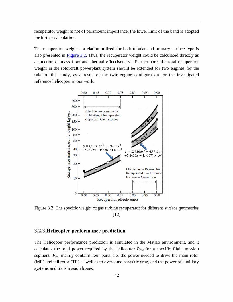
42
recuperator weight is not of paramount importance, the lower limit of the band is adopted
for further calculation.
The recuperator weight correlation utilized for both tubular and primary surface type is
also presented in Figure 3.2. Thus, the recuperator weight could be calculated directly as
a function of mass flow and thermal effectiveness. Furthermore, the total recuperator
weight in the rotorcraft powerplant system should be extended for two engines for the
sake of this study, as a result of the twin-engine configuration for the investigated
reference helicopter in our work.
Figure 3.2: The specific weight of gas turbine recuperator for different surface geometries
[12]
3.2.3 Helicopter performance prediction
The Helicopter performance prediction is simulated in the Matlab environment, and it
calculates the total power required by the helicopter Preq for a specific flight mission
segment. Preq mainly contains four parts, i.e. the power needed to drive the main rotor
(MR) and tail rotor (TR) as well as to overcome parasitic drag, and the power of auxiliary
systems and transmission losses.
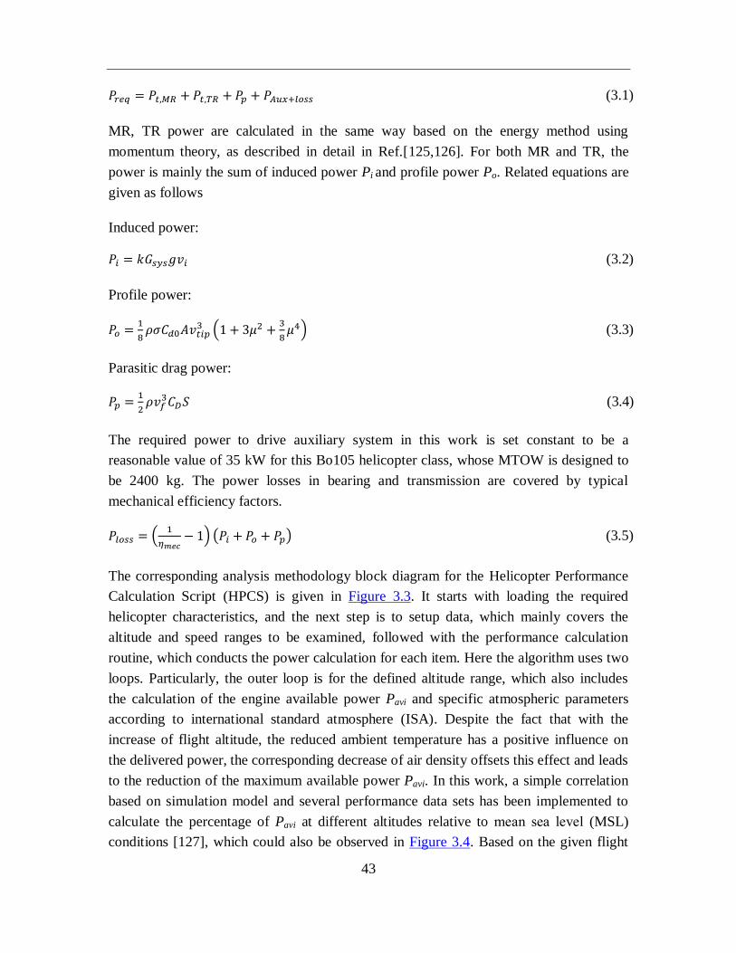
43
𝑃𝑟𝑒𝑞 = 𝑃𝑡,𝑀𝑅 + 𝑃𝑡,𝑇𝑅 + 𝑃𝑝 + 𝑃𝐴𝑢𝑥+𝑙𝑜𝑠𝑠 (3.1)
MR, TR power are calculated in the same way based on the energy method using
momentum theory, as described in detail in Ref.[125,126]. For both MR and TR, the
power is mainly the sum of induced power Pi and profile power Po. Related equations are
given as follows
Induced power:
𝑃𝑖 = 𝑘𝐺𝑠𝑦𝑠𝑔𝑣𝑖 (3.2)
Profile power:
𝑃𝑜 =1
8𝜌𝜎𝐶𝑑0𝐴𝑣𝑡𝑖𝑝
3 (1 + 3𝜇2 +3
8𝜇4) (3.3)
Parasitic drag power:
𝑃𝑝 =1
2𝜌𝑣𝑓
3𝐶𝐷𝑆 (3.4)
The required power to drive auxiliary system in this work is set constant to be a
reasonable value of 35 kW for this Bo105 helicopter class, whose MTOW is designed to
be 2400 kg. The power losses in bearing and transmission are covered by typical
mechanical efficiency factors.
𝑃𝑙𝑜𝑠𝑠 = (1
𝜂𝑚𝑒𝑐− 1) (𝑃𝑖 + 𝑃𝑜 + 𝑃𝑝) (3.5)
The corresponding analysis methodology block diagram for the Helicopter Performance
Calculation Script (HPCS) is given in Figure 3.3. It starts with loading the required
helicopter characteristics, and the next step is to setup data, which mainly covers the
altitude and speed ranges to be examined, followed with the performance calculation
routine, which conducts the power calculation for each item. Here the algorithm uses two
loops. Particularly, the outer loop is for the defined altitude range, which also includes
the calculation of the engine available power Pavi and specific atmospheric parameters
according to international standard atmosphere (ISA). Despite the fact that with the
increase of flight altitude, the reduced ambient temperature has a positive influence on
the delivered power, the corresponding decrease of air density offsets this effect and leads
to the reduction of the maximum available power Pavi. In this work, a simple correlation
based on simulation model and several performance data sets has been implemented to
calculate the percentage of Pavi at different altitudes relative to mean sea level (MSL)
conditions [127], which could also be observed in Figure 3.4. Based on the given flight
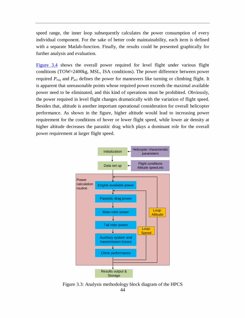
44
speed range, the inner loop subsequently calculates the power consumption of every
individual component. For the sake of better code maintainability, each item is defined
with a separate Matlab-function. Finally, the results could be presented graphically for
further analysis and evaluation.
Figure 3.4 shows the overall power required for level flight under various flight
conditions (TOW=2400kg, MSL, ISA conditions).The power difference between power
required Preq and Pavi defines the power for maneuvers like turning or climbing flight. It
is apparent that unreasonable points whose required power exceeds the maximal available
power need to be eliminated, and this kind of operations must be prohibited. Obviously,
the power required in level flight changes dramatically with the variation of flight speed.
Besides that, altitude is another important operational consideration for overall helicopter
performance. As shown in the figure, higher altitude would lead to increasing power
requirement for the conditions of hover or lower flight speed, while lower air density at
higher altitude decreases the parasitic drag which plays a dominant role for the overall
power requirement at larger flight speed.
Initialization
Data set up
Helicopter characteristic
parameters
Flight conditions
Altitude speed,etc
Engine available power
Tail rotor power
Parasitic drag power
Main rotor power
Results output &
Storage
Power
calculation
routine
Auxiliary system and
transimission losses
Climb performance
Loop:
Speed
Loop:
Altitude
Figure 3.3: Analysis methodology block diagram of the HPCS
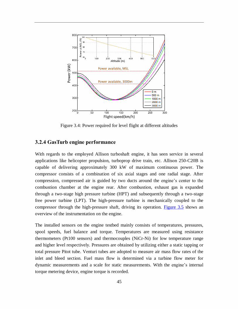
45
Figure 3.4: Power required for level flight at different altitudes
3.2.4 GasTurb engine performance
With regards to the employed Allison turboshaft engine, it has seen service in several
applications like helicopter propulsion, turboprop drive train, etc. Allison 250-C20B is
capable of delivering approximately 300 kW of maximum continuous power. The
compressor consists of a combination of six axial stages and one radial stage. After
compression, compressed air is guided by two ducts around the engine’s center to the
combustion chamber at the engine rear. After combustion, exhaust gas is expanded
through a two-stage high pressure turbine (HPT) and subsequently through a two-stage
free power turbine (LPT). The high-pressure turbine is mechanically coupled to the
compressor through the high-pressure shaft, driving its operation. Figure 3.5 shows an
overview of the instrumentation on the engine.
The installed sensors on the engine testbed mainly consists of temperatures, pressures,
spool speeds, fuel balance and torque. Temperatures are measured using resistance
thermometers (Pt100 sensors) and thermocouples (NiCr-Ni) for low temperature range
and higher level respectively. Pressures are obtained by utilizing either a static tapping or
total pressure Pitot tube. Venturi tubes are adopted to measure air mass flow rates of the
inlet and bleed section. Fuel mass flow is determined via a turbine flow meter for
dynamic measurements and a scale for static measurements. With the engine’s internal
torque metering device, engine torque is recorded.
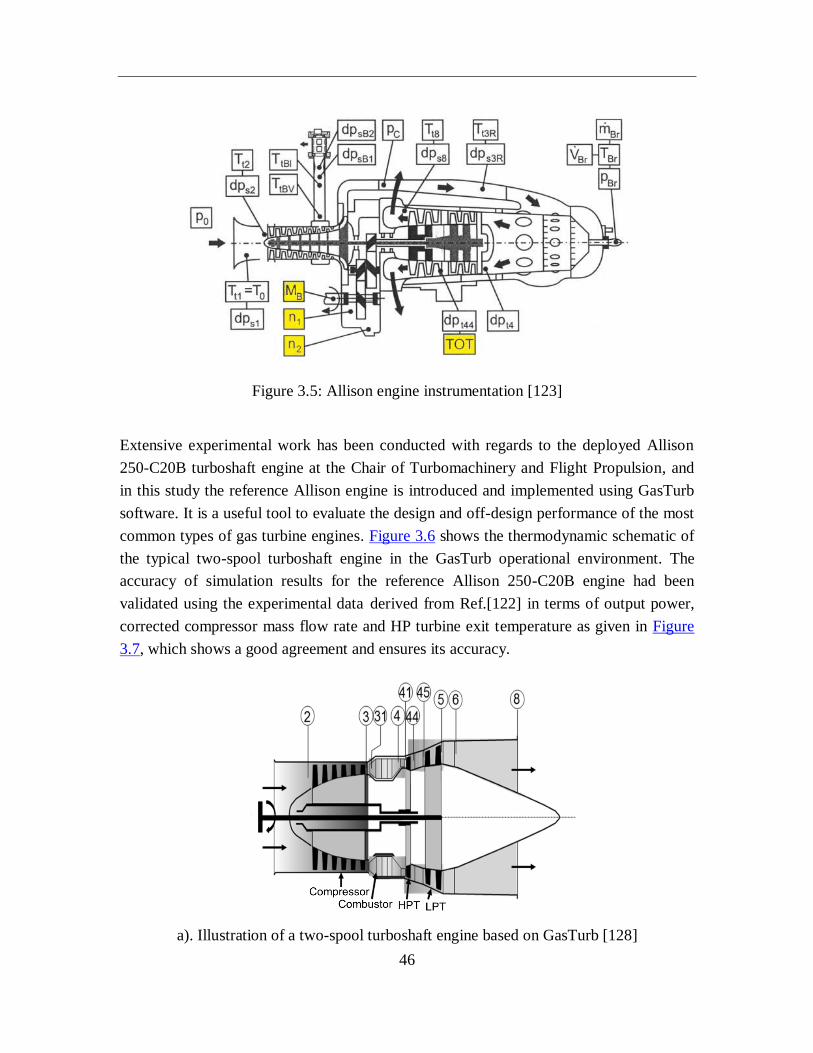
46
Figure 3.5: Allison engine instrumentation [123]
Extensive experimental work has been conducted with regards to the deployed Allison
250-C20B turboshaft engine at the Chair of Turbomachinery and Flight Propulsion, and
in this study the reference Allison engine is introduced and implemented using GasTurb
software. It is a useful tool to evaluate the design and off-design performance of the most
common types of gas turbine engines. Figure 3.6 shows the thermodynamic schematic of
the typical two-spool turboshaft engine in the GasTurb operational environment. The
accuracy of simulation results for the reference Allison 250-C20B engine had been
validated using the experimental data derived from Ref.[122] in terms of output power,
corrected compressor mass flow rate and HP turbine exit temperature as given in Figure
3.7, which shows a good agreement and ensures its accuracy.
a). Illustration of a two-spool turboshaft engine based on GasTurb [128]
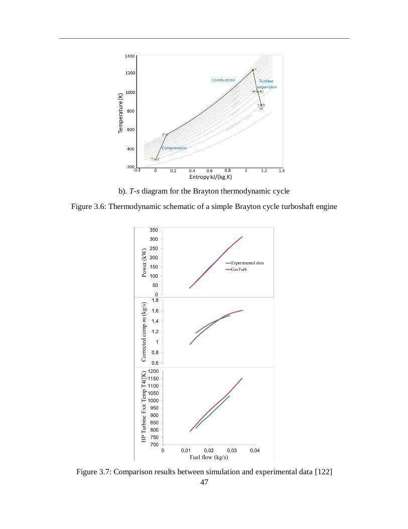
47
b). T-s diagram for the Brayton thermodynamic cycle
Figure 3.6: Thermodynamic schematic of a simple Brayton cycle turboshaft engine
Figure 3.7: Comparison results between simulation and experimental data [122]
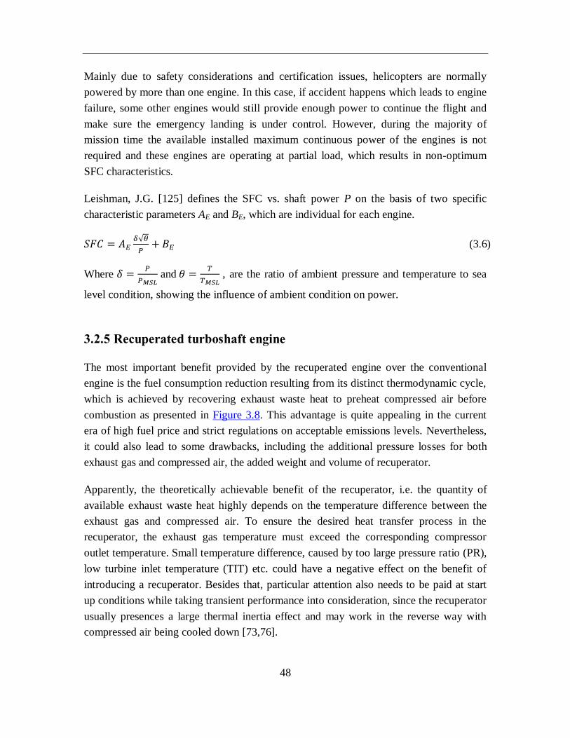
48
Mainly due to safety considerations and certification issues, helicopters are normally
powered by more than one engine. In this case, if accident happens which leads to engine
failure, some other engines would still provide enough power to continue the flight and
make sure the emergency landing is under control. However, during the majority of
mission time the available installed maximum continuous power of the engines is not
required and these engines are operating at partial load, which results in non-optimum
SFC characteristics.
Leishman, J.G. [125] defines the SFC vs. shaft power P on the basis of two specific
characteristic parameters AE and BE, which are individual for each engine.
𝑆𝐹𝐶 = 𝐴𝐸𝛿√𝜃
𝑃+ 𝐵𝐸 (3.6)
Where 𝛿 =𝑃
𝑃𝑀𝑆𝐿 and 𝜃 =
𝑇
𝑇𝑀𝑆𝐿 , are the ratio of ambient pressure and temperature to sea
level condition, showing the influence of ambient condition on power.
3.2.5 Recuperated turboshaft engine
The most important benefit provided by the recuperated engine over the conventional
engine is the fuel consumption reduction resulting from its distinct thermodynamic cycle,
which is achieved by recovering exhaust waste heat to preheat compressed air before
combustion as presented in Figure 3.8. This advantage is quite appealing in the current
era of high fuel price and strict regulations on acceptable emissions levels. Nevertheless,
it could also lead to some drawbacks, including the additional pressure losses for both
exhaust gas and compressed air, the added weight and volume of recuperator.
Apparently, the theoretically achievable benefit of the recuperator, i.e. the quantity of
available exhaust waste heat highly depends on the temperature difference between the
exhaust gas and compressed air. To ensure the desired heat transfer process in the
recuperator, the exhaust gas temperature must exceed the corresponding compressor
outlet temperature. Small temperature difference, caused by too large pressure ratio (PR),
low turbine inlet temperature (TIT) etc. could have a negative effect on the benefit of
introducing a recuperator. Besides that, particular attention also needs to be paid at start
up conditions while taking transient performance into consideration, since the recuperator
usually presences a large thermal inertia effect and may work in the reverse way with
compressed air being cooled down [73,76].
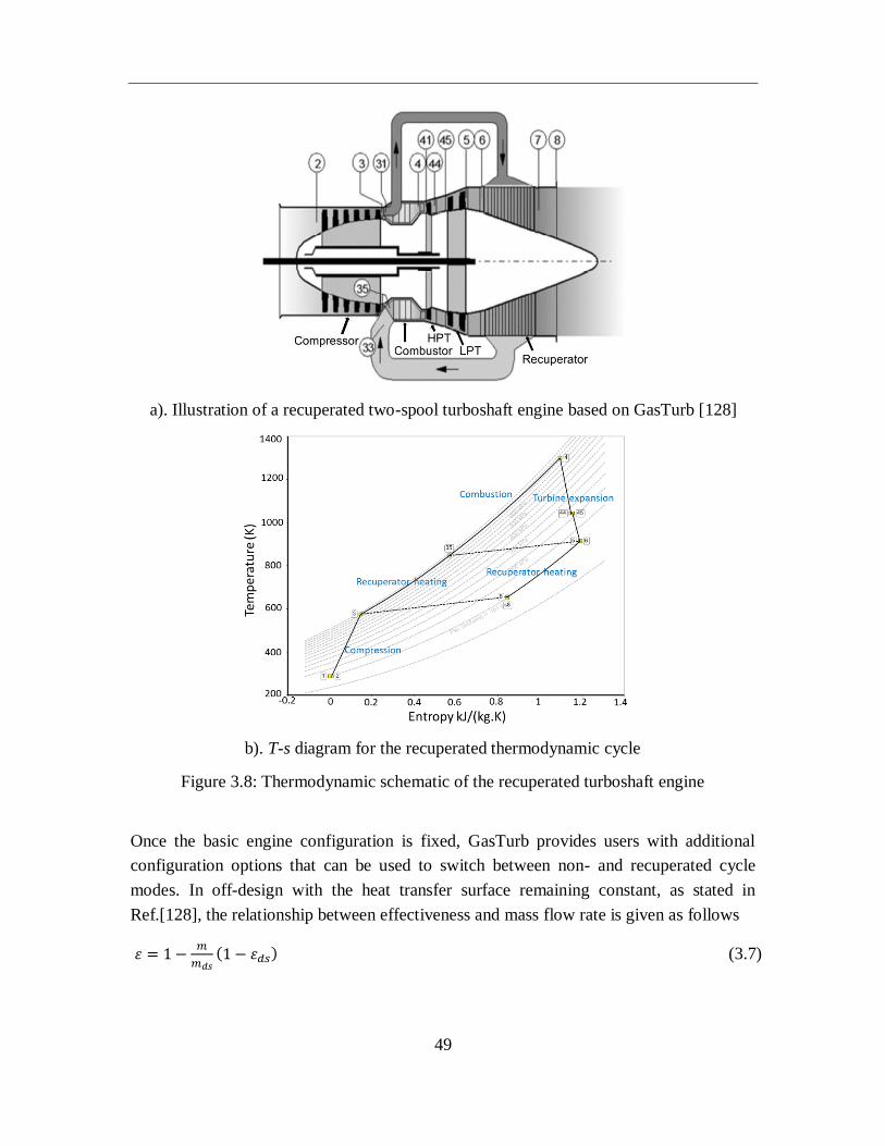
49
a). Illustration of a recuperated two-spool turboshaft engine based on GasTurb [128]
b). T-s diagram for the recuperated thermodynamic cycle
Figure 3.8: Thermodynamic schematic of the recuperated turboshaft engine
Once the basic engine configuration is fixed, GasTurb provides users with additional
configuration options that can be used to switch between non- and recuperated cycle
modes. In off-design with the heat transfer surface remaining constant, as stated in
Ref.[128], the relationship between effectiveness and mass flow rate is given as follows
휀 = 1 −𝑚
𝑚𝑑𝑠(1 − 휀𝑑𝑠) (3.7)
50
The following formulae are given to depict the relationship of pressure losses on the
cold/hot side of the recuperator between off-design and design point.
For compressor air, cold side (inlet 1, outlet 2)
𝑝1−𝑝2
𝑝1= (
𝑝1−𝑝2
𝑝1)
𝑑𝑠
(𝑚1𝑝1
)2𝑇2
1.55
𝑇10.55
(𝑚1𝑝1
)𝑑𝑠
2 𝑇2,𝑑𝑠1.55
𝑇1,𝑑𝑠0.55
(3.8)
For exhaust gas, hot side
𝑝1−𝑝2
𝑝1= (
𝑝1−𝑝2
𝑝1)
𝑑𝑠
𝑚12𝑇1
(𝑚12𝑇1)
𝑑𝑠
(3.9)
3.3 Mission investigation
With regards to the majority of typical rotorcraft applications (e.g. surveillance, fire
suppression, search and rescue etc.), the rotorcraft is often utilized for occasions where
environmental concerns would be considered secondary, and the main focuses of this
study are therefore placed on fuel economy improvement and system weight
minimization for the purpose of maximizing rotorcraft range and payload capability.
Incorporating recuperators into gas turbine systems enables the heat transfer between the
exhaust gas and compressed air, thus a remarkable increase in compressed air
temperature, prior to the combustion chamber is expected. As a result, less fuel
consumption is required to heat the compressed air/fuel mixture up to the desired turbine
inlet temperature, indicating considerable potential for lower emissions and SFC.
The additional recuperator could definitely increase the system’s overall weight, thus
acting as a weight penalty for recuperated cycle performance, meanwhile, the fuel
consumption for a given mission would be decreased resulting from the improved fuel
economy and thermal efficiency. When considering the combined weight of the heavier
engine configuration and potentially reduced fuel consumption, the point at which the
amount of fuel saved could exactly compensate the additional recuperator weight is
defined as the ‘equilibrium point’. Apparently, for a specific mission the adoption of
recuperator would be beneficial under the condition that this equilibrium point is at least
satisfied, otherwise, the parasitic recuperator weight would outweigh the benefits of
lower SFC. Here ∆M is denoted as the weight difference between the added recuperator
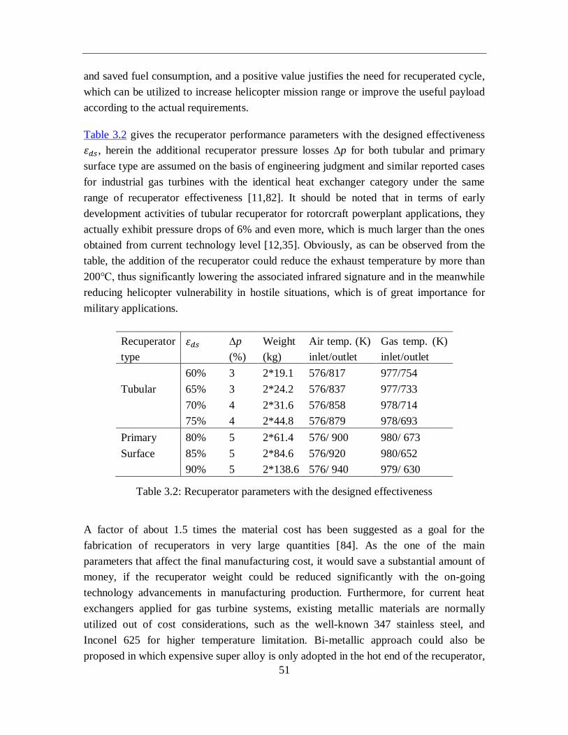
51
and saved fuel consumption, and a positive value justifies the need for recuperated cycle,
which can be utilized to increase helicopter mission range or improve the useful payload
according to the actual requirements.
Table 3.2 gives the recuperator performance parameters with the designed effectiveness
휀𝑑𝑠 , herein the additional recuperator pressure losses ∆p for both tubular and primary
surface type are assumed on the basis of engineering judgment and similar reported cases
for industrial gas turbines with the identical heat exchanger category under the same
range of recuperator effectiveness [11,82]. It should be noted that in terms of early
development activities of tubular recuperator for rotorcraft powerplant applications, they
actually exhibit pressure drops of 6% and even more, which is much larger than the ones
obtained from current technology level [12,35]. Obviously, as can be observed from the
table, the addition of the recuperator could reduce the exhaust temperature by more than
200℃, thus significantly lowering the associated infrared signature and in the meanwhile
reducing helicopter vulnerability in hostile situations, which is of great importance for
military applications.
Recuperator
type
휀𝑑𝑠 ∆p
(%)
Weight
(kg)
Air temp. (K)
inlet/outlet
Gas temp. (K)
inlet/outlet
60% 3 2*19.1 576/817 977/754
Tubular 65% 3 2*24.2 576/837 977/733
70% 4 2*31.6 576/858 978/714
75% 4 2*44.8 576/879 978/693
Primary 80% 5 2*61.4 576/ 900 980/ 673
Surface 85% 5 2*84.6 576/920 980/652
90% 5 2*138.6 576/ 940 979/ 630
Table 3.2: Recuperator parameters with the designed effectiveness
A factor of about 1.5 times the material cost has been suggested as a goal for the
fabrication of recuperators in very large quantities [84]. As the one of the main
parameters that affect the final manufacturing cost, it would save a substantial amount of
money, if the recuperator weight could be reduced significantly with the on-going
technology advancements in manufacturing production. Furthermore, for current heat
exchangers applied for gas turbine systems, existing metallic materials are normally
utilized out of cost considerations, such as the well-known 347 stainless steel, and
Inconel 625 for higher temperature limitation. Bi-metallic approach could also be
proposed in which expensive super alloy is only adopted in the hot end of the recuperator,
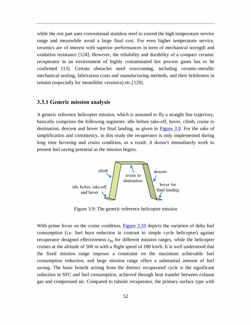
52
while the rest part uses conventional stainless steel to extend the high temperature service
range and meanwhile avoid a large final cost. For even higher temperature service,
ceramics are of interest with superior performances in term of mechanical strength and
oxidation resistance [124]. However, the reliability and durability of a compact ceramic
recuperator in an environment of highly contaminated hot process gases has to be
confirmed [13]. Certain obstacles need overcoming, including ceramic-metallic
mechanical sealing, fabrication costs and manufacturing methods, and their brittleness in
tension (especially for monolithic ceramics) etc.[129].
3.3.1 Generic mission analysis
A generic reference helicopter mission, which is assumed to fly a straight line trajectory,
basically comprises the following segments: idle before take-off, hover, climb, cruise to
destination, descent and hover for final landing, as given in Figure 3.9. For the sake of
simplification and consistency, in this study the recuperator is only implemented during
long time hovering and cruise condition, as a result, it doesn’t immediately work to
present fuel saving potential as the mission begins.
Figure 3.9: The generic reference helicopter mission
With prime focus on the cruise condition, Figure 3.10 depicts the variation of delta fuel
consumption (i.e. fuel burn reduction in contrast to simple cycle helicopter) against
recuperator designed effectiveness 휀𝑑𝑠 for different mission ranges, while the helicopter
cruises at the altitude of 500 m with a flight speed of 180 km/h. It is well understood that
the fixed mission range imposes a constraint on the maximum achievable fuel
consumption reduction, and large mission range offers a substantial amount of fuel
saving. The basic benefit arising from the distinct recuperated cycle is the significant
reduction in SFC and fuel consumption, achieved through heat transfer between exhaust
gas and compressed air. Compared to tubular recuperator, the primary surface type with
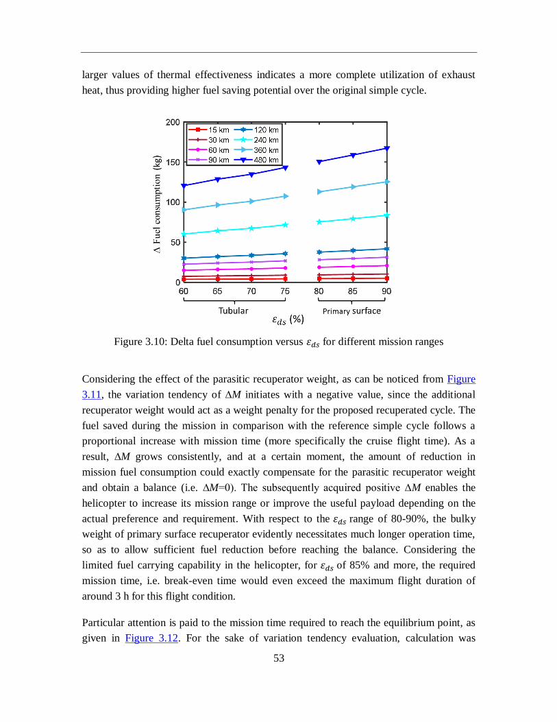
53
larger values of thermal effectiveness indicates a more complete utilization of exhaust
heat, thus providing higher fuel saving potential over the original simple cycle.
Figure 3.10: Delta fuel consumption versus 휀𝑑𝑠 for different mission ranges
Considering the effect of the parasitic recuperator weight, as can be noticed from Figure
3.11, the variation tendency of ∆M initiates with a negative value, since the additional
recuperator weight would act as a weight penalty for the proposed recuperated cycle. The
fuel saved during the mission in comparison with the reference simple cycle follows a
proportional increase with mission time (more specifically the cruise flight time). As a
result, ∆M grows consistently, and at a certain moment, the amount of reduction in
mission fuel consumption could exactly compensate for the parasitic recuperator weight
and obtain a balance (i.e. ∆M=0). The subsequently acquired positive ∆M enables the
helicopter to increase its mission range or improve the useful payload depending on the
actual preference and requirement. With respect to the 휀𝑑𝑠 range of 80-90%, the bulky
weight of primary surface recuperator evidently necessitates much longer operation time,
so as to allow sufficient fuel reduction before reaching the balance. Considering the
limited fuel carrying capability in the helicopter, for 휀𝑑𝑠 of 85% and more, the required
mission time, i.e. break-even time would even exceed the maximum flight duration of
around 3 h for this flight condition.
Particular attention is paid to the mission time required to reach the equilibrium point, as
given in Figure 3.12. For the sake of variation tendency evaluation, calculation was
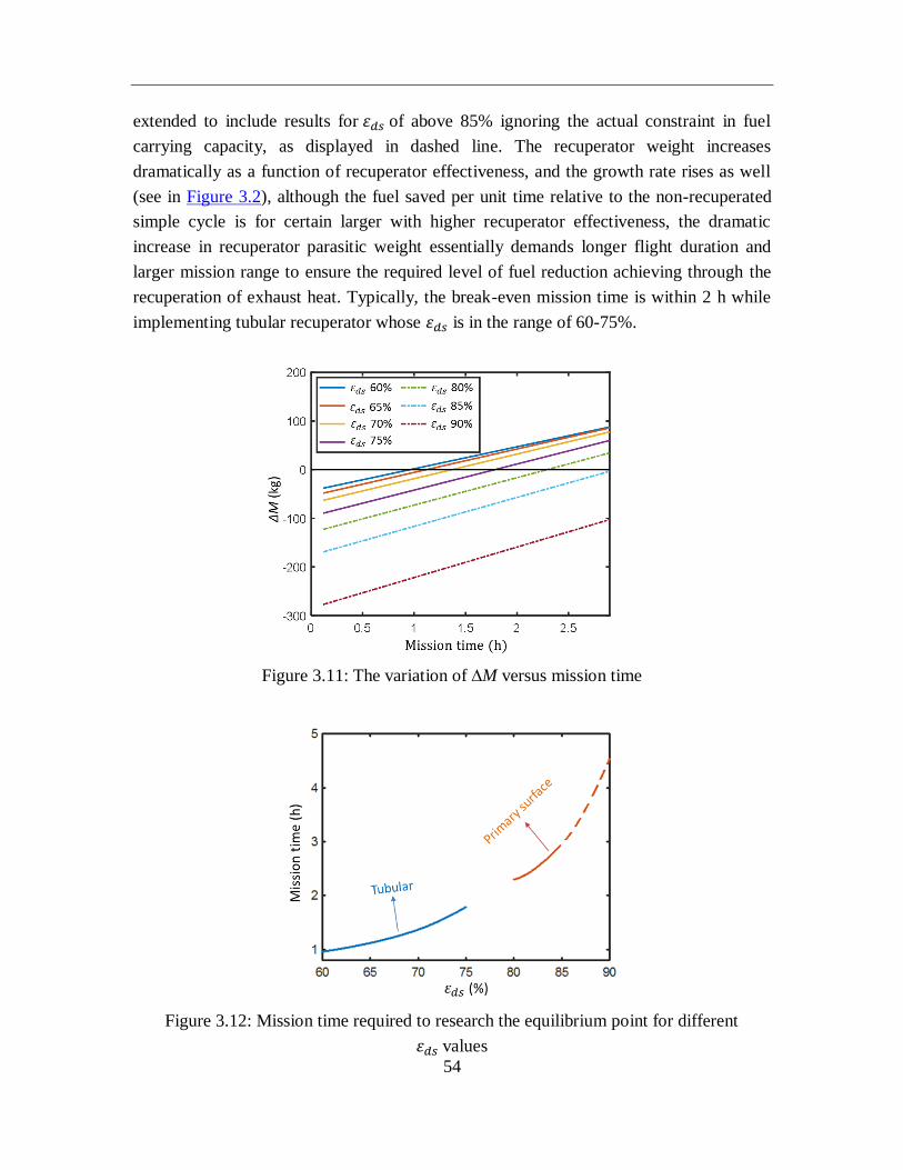
54
extended to include results for 휀𝑑𝑠 of above 85% ignoring the actual constraint in fuel
carrying capacity, as displayed in dashed line. The recuperator weight increases
dramatically as a function of recuperator effectiveness, and the growth rate rises as well
(see in Figure 3.2), although the fuel saved per unit time relative to the non-recuperated
simple cycle is for certain larger with higher recuperator effectiveness, the dramatic
increase in recuperator parasitic weight essentially demands longer flight duration and
larger mission range to ensure the required level of fuel reduction achieving through the
recuperation of exhaust heat. Typically, the break-even mission time is within 2 h while
implementing tubular recuperator whose 휀𝑑𝑠 is in the range of 60-75%.
Figure 3.11: The variation of ∆M versus mission time
Figure 3.12: Mission time required to research the equilibrium point for different
휀𝑑𝑠 values
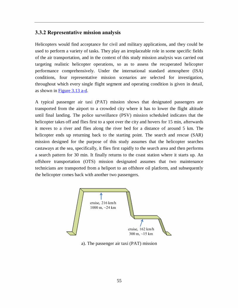
55
3.3.2 Representative mission analysis
Helicopters would find acceptance for civil and military applications, and they could be
used to perform a variety of tasks. They play an irreplaceable role in some specific fields
of the air transportation, and in the context of this study mission analysis was carried out
targeting realistic helicopter operations, so as to assess the recuperated helicopter
performance comprehensively. Under the international standard atmosphere (ISA)
conditions, four representative mission scenarios are selected for investigation,
throughout which every single flight segment and operating condition is given in detail,
as shown in Figure 3.13 a-d.
A typical passenger air taxi (PAT) mission shows that designated passengers are
transported from the airport to a crowded city where it has to lower the flight altitude
until final landing. The police surveillance (PSV) mission scheduled indicates that the
helicopter takes off and flies first to a spot over the city and hovers for 15 min, afterwards
it moves to a river and flies along the river bed for a distance of around 5 km. The
helicopter ends up returning back to the starting point. The search and rescue (SAR)
mission designed for the purpose of this study assumes that the helicopter searches
castaways at the sea, specifically, it flies first rapidly to the search area and then performs
a search pattern for 30 min. It finally returns to the coast station where it starts up. An
offshore transportation (OTS) mission designated assumes that two maintenance
technicians are transported from a heliport to an offshore oil platform, and subsequently
the helicopter comes back with another two passengers.
a). The passenger air taxi (PAT) mission
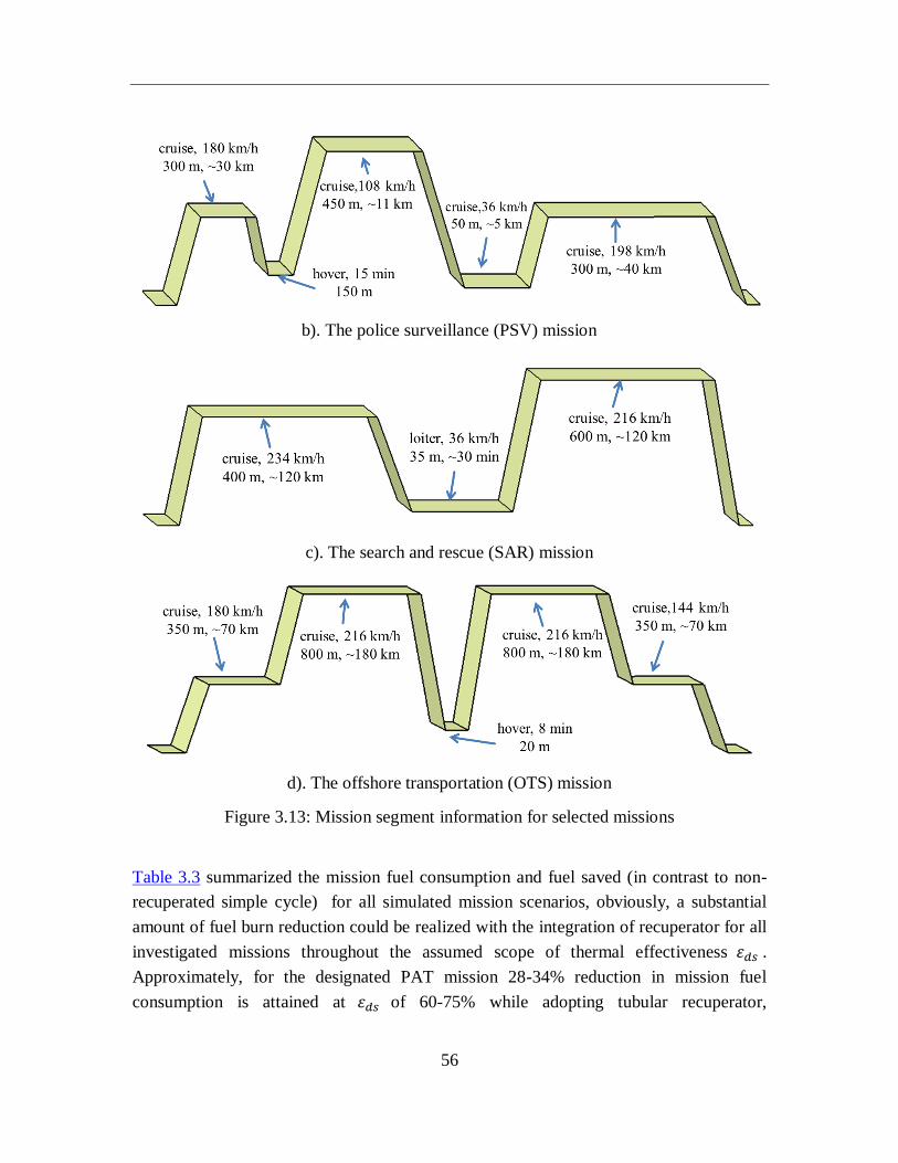
56
b). The police surveillance (PSV) mission
c). The search and rescue (SAR) mission
d). The offshore transportation (OTS) mission
Figure 3.13: Mission segment information for selected missions
Table 3.3 summarized the mission fuel consumption and fuel saved (in contrast to non-
recuperated simple cycle) for all simulated mission scenarios, obviously, a substantial
amount of fuel burn reduction could be realized with the integration of recuperator for all
investigated missions throughout the assumed scope of thermal effectiveness 휀𝑑𝑠 .
Approximately, for the designated PAT mission 28-34% reduction in mission fuel
consumption is attained at 휀𝑑𝑠 of 60-75% while adopting tubular recuperator,
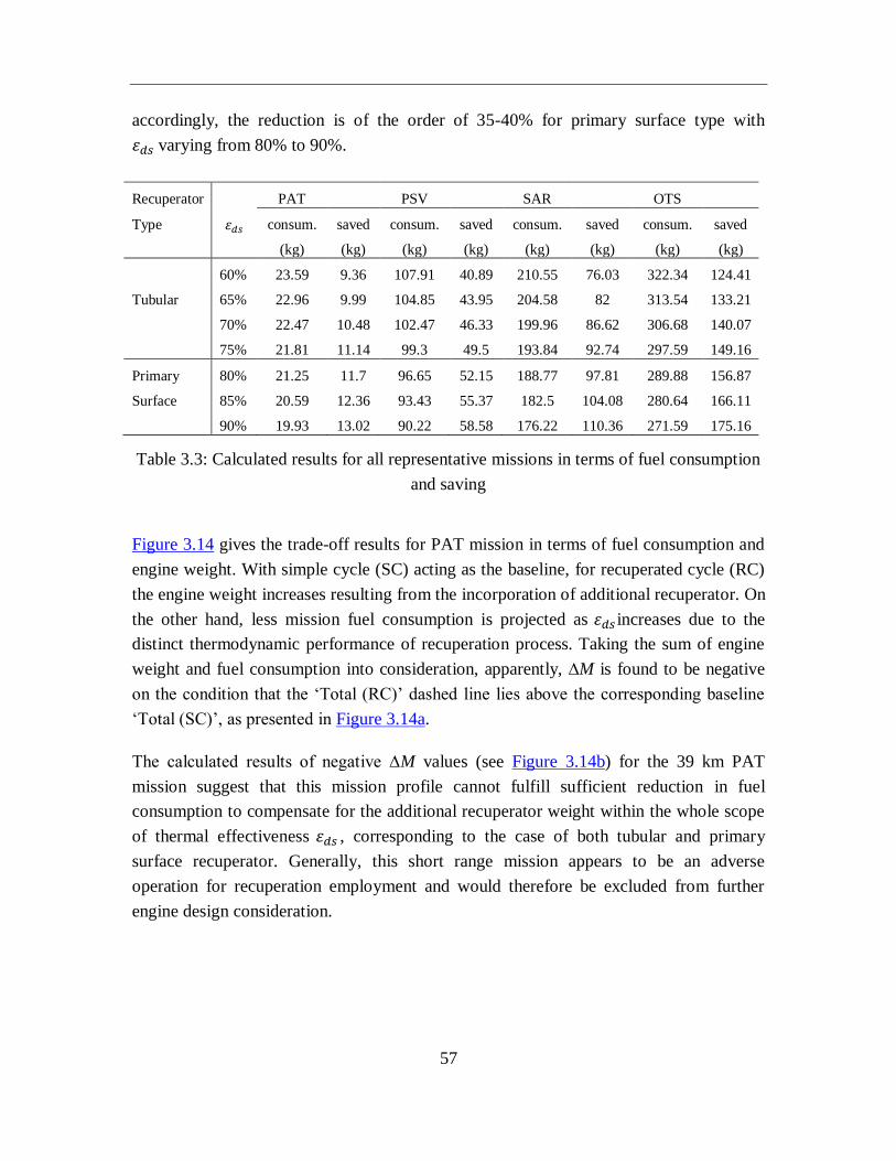
57
accordingly, the reduction is of the order of 35-40% for primary surface type with
휀𝑑𝑠 varying from 80% to 90%.
Recuperator PAT PSV SAR OTS
Type 휀𝑑𝑠 consum.
(kg)
saved
(kg)
consum.
(kg)
saved
(kg)
consum.
(kg)
saved
(kg)
consum.
(kg)
saved
(kg)
60% 23.59 9.36 107.91 40.89 210.55 76.03 322.34 124.41
Tubular 65% 22.96 9.99 104.85 43.95 204.58 82 313.54 133.21
70% 22.47 10.48 102.47 46.33 199.96 86.62 306.68 140.07
75% 21.81 11.14 99.3 49.5 193.84 92.74 297.59 149.16
Primary 80% 21.25 11.7 96.65 52.15 188.77 97.81 289.88 156.87
Surface 85% 20.59 12.36 93.43 55.37 182.5 104.08 280.64 166.11
90% 19.93 13.02 90.22 58.58 176.22 110.36 271.59 175.16
Table 3.3: Calculated results for all representative missions in terms of fuel consumption
and saving
Figure 3.14 gives the trade-off results for PAT mission in terms of fuel consumption and
engine weight. With simple cycle (SC) acting as the baseline, for recuperated cycle (RC)
the engine weight increases resulting from the incorporation of additional recuperator. On
the other hand, less mission fuel consumption is projected as 휀𝑑𝑠 increases due to the
distinct thermodynamic performance of recuperation process. Taking the sum of engine
weight and fuel consumption into consideration, apparently, ∆M is found to be negative
on the condition that the ‘Total (RC)’ dashed line lies above the corresponding baseline
‘Total (SC)’, as presented in Figure 3.14a.
The calculated results of negative ∆M values (see Figure 3.14b) for the 39 km PAT
mission suggest that this mission profile cannot fulfill sufficient reduction in fuel
consumption to compensate for the additional recuperator weight within the whole scope
of thermal effectiveness 휀𝑑𝑠 , corresponding to the case of both tubular and primary
surface recuperator. Generally, this short range mission appears to be an adverse
operation for recuperation employment and would therefore be excluded from further
engine design consideration.
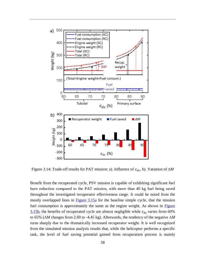
58
Figure 3.14: Trade-off results for PAT mission: a). Influence of 휀𝑑𝑠, b). Variation of ∆M
Benefit from the recuperated cycle, PSV mission is capable of exhibiting significant fuel
burn reduction compared to the PAT mission, with more than 40 kg fuel being saved
throughout the investigated recuperator effectiveness range. It could be noted from the
mostly overlapped lines in Figure 3.15a for the baseline simple cycle, that the mission
fuel consumption is approximately the same as the engine weight. As shown in Figure
3.15b, the benefits of recuperated cycle are almost negligible while 휀𝑑𝑠 varies from 60%
to 65% (∆M changes from 2.69 to -4.45 kg). Afterwards, the tendency of the negative ∆M
turns sharply due to the dramatically increased recuperator weight. It is well recognized
from the simulated mission analysis results that, while the helicopter performs a specific
task, the level of fuel saving potential gained from recuperation process is mainly
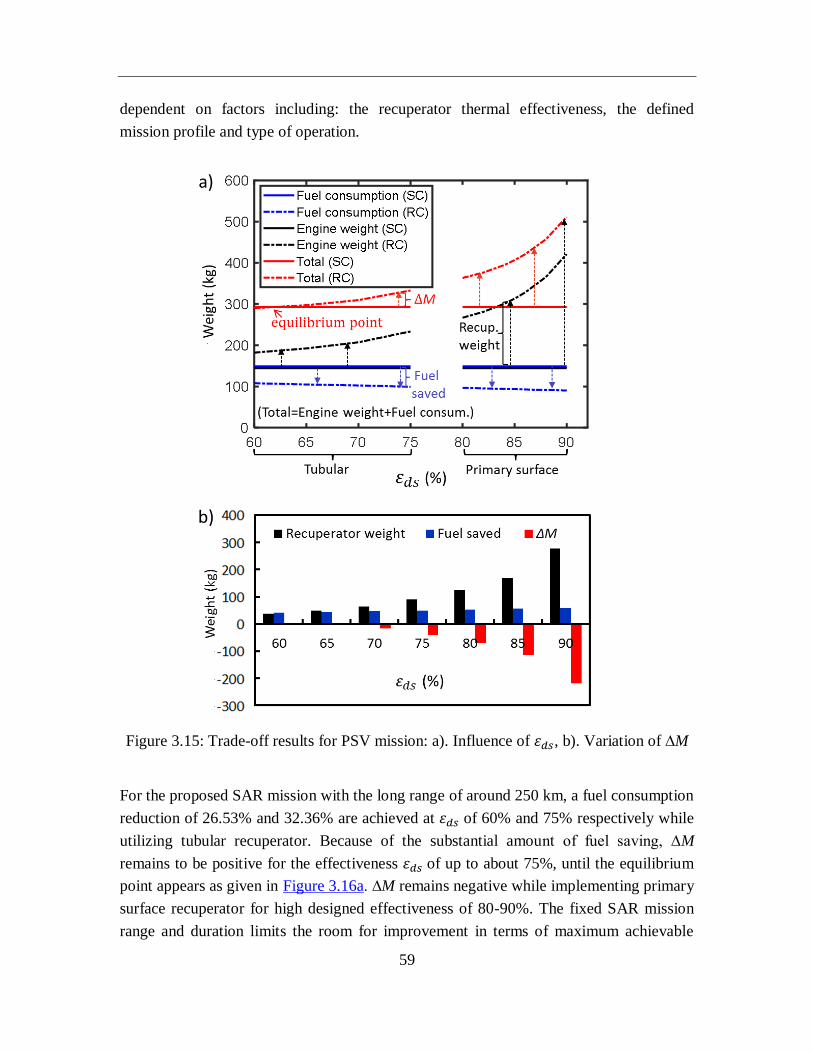
59
dependent on factors including: the recuperator thermal effectiveness, the defined
mission profile and type of operation.
Figure 3.15: Trade-off results for PSV mission: a). Influence of 휀𝑑𝑠, b). Variation of ∆M
For the proposed SAR mission with the long range of around 250 km, a fuel consumption
reduction of 26.53% and 32.36% are achieved at 휀𝑑𝑠 of 60% and 75% respectively while
utilizing tubular recuperator. Because of the substantial amount of fuel saving, ∆M
remains to be positive for the effectiveness 휀𝑑𝑠 of up to about 75%, until the equilibrium
point appears as given in Figure 3.16a. ∆M remains negative while implementing primary
surface recuperator for high designed effectiveness of 80-90%. The fixed SAR mission
range and duration limits the room for improvement in terms of maximum achievable
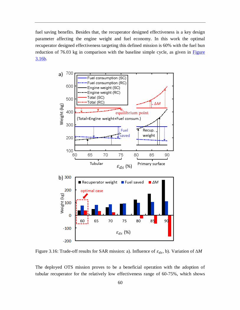
60
fuel saving benefits. Besides that, the recuperator designed effectiveness is a key design
parameter affecting the engine weight and fuel economy. In this work the optimal
recuperator designed effectiveness targeting this defined mission is 60% with the fuel bun
reduction of 76.03 kg in comparison with the baseline simple cycle, as given in Figure
3.16b.
Figure 3.16: Trade-off results for SAR mission: a). Influence of 휀𝑑𝑠, b). Variation of ∆M
The deployed OTS mission proves to be a beneficial operation with the adoption of
tubular recuperator for the relatively low effectiveness range of 60-75%, which shows
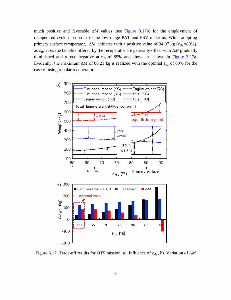
61
much positive and favorable ∆M values (see Figure 3.17b) for the employment of
recuperated cycle in contrast to the low range PAT and PSV missions. While adopting
primary surface recuperator, ∆M initiates with a positive value of 34.07 kg (휀𝑑𝑠=80%),
as 휀𝑑𝑠 rises the benefits offered by the recuperator are generally offset with ∆M gradually
diminished and turned negative at 휀𝑑𝑠 of 85% and above, as shown in Figure 3.17a.
Evidently, the maximum ∆M of 86.21 kg is realized with the optimal 휀𝑑𝑠 of 60% for the
case of using tubular recuperator.
Figure 3.17: Trade-off results for OTS mission: a). Influence of 휀𝑑𝑠, b). Variation of ∆M
62
It is found that ∆M remains negative with 휀𝑑𝑠 of 90% for all simulated missions,
highlighting the requirement for the new generation of lightweight, highly effective,
compact heat exchanger. Probably because of the small hydraulic diameter, in Ref.[97]
the calculated results for the design of primary surface recuperator applicable to
microturbines exhibit much smaller weight and volume compared to available examples
of operating recuperators. In fact, their volumes are approximately 30% less than the
expectation made on the basis of primary surface recuperators of actual cases. Primary
surface geometry with smaller hydraulic diameters (thus increasing compactness) may be
an appropriate candidate for future highly effective rotorcraft recuperator, however,
associated limitations includes flow maldistribution, longitudinal conduction effects and
fouling.
3.4 Summary
Even though the benefits of implementing recuperators have long been recognized, and
recuperators have been widely accepted as necessary components to achieve high thermal
efficiency for microturbines, they have not found good acceptance in aircraft
applications. The operating characteristics of rotorcraft impose unique requirements on
engine propulsion systems in contrast to industrial gas turbines, among which a major
recuperator demand is light weight. Besides the appealing fuel saving advantage, the
integration of recuperators definitely weakens the attractive power-to-weight ratios
provided by gas turbines in comparison with reciprocating engines. As a result, the
adoption of recuperators therefore leads to conflicting design requirements. Based on
previous development activities of recuperated rotorcrafts, tubular recuperator is
primarily considered with relatively low effectiveness, while primary surface type would
be an appropriate choice for higher level of effectiveness. In this work, it has been
proposed to quantify the interrelationship and associated trade-off between improved fuel
economy and unfavorable parasitic weight in the recuperated cycle for a wide range of
effectiveness, saying 60-75% for tubular recuperator and 80-90% for primary surface
type.
An integrated multidisciplinary simulation framework has been implemented to
comprehensively assess the performance of the proposed helicopter at mission levels for
both simple and recuperated cycles. Extensive comparisons are carried out and presented
for a generic reference mission providing general characteristics between aforementioned
conflicting objectives and four representative missions targeting realistic helicopter
operations. The trade-off study at mission levels has been developed to identify the

63
optimal recuperator design effectiveness that represents the maximum fuel saving
potential applicable to the specified mission for the investigated recuperated helicopter.
The fuel saving capacity of the adopted recuperator is highly dependent on the mission
profile and flight duration. It has been emphasized that although the employed
recuperated engine could substantially improve thermal efficiency and reduce fuel
consumption, the selection of high value of effectiveness (with the implementation of
primary surface recuperator) may not be suitable in certain cases (particularly missions
with short range) for further recuperator design, considering the inherited dramatic
growth in weight penalty.
64
4. The potential of rotorcraft powerplant
incorporating highly effective recuperators
Incorporating recuperators into gas turbines shows considerable potential for lower
emissions and fuel consumption. Nowadays the technology readiness of advanced
compact heat exchanger has provided a solid foundation for the availability of
lightweight, higher efficient recuperators which would find good acceptance on the
rotorcraft without penalizing the operational capabilities.
In this work, the previously developed system simulation methodology and performance
assessment approach corresponding to a typical multi-purpose utility helicopter Bo105,
has been further implemented to evaluate the potential of recuperated helicopter
turboshaft engine, which is equipped with compact primary surface heat exchanger for a
high level of thermal effectiveness, saying 80-90%. The improved part-load performance
against the reference non-recuperated simple cycle is discussed at first, and the study is
then extended to evaluate the fuel saving potential of recuperated helicopter under the
flight condition of 0-250 km/h and 0-3000 m, with regards to different recuperator design
effectiveness values. This is achieved through the quantification of the helicopter flight
time required to provide enough saved fuel, so as to compensate for the additional
recuperator weight. Furthermore, the influence of recuperator size and corresponding
installation have been also taken into consideration.
4.1 Highly effective primary surface recuperator
A recuperator exhibits tremendous potential in the gas turbine system to reduce fuel
consumption and improve thermal efficiency. With regards to its application on
aeroengines, in addition to cost considerations, generally the main features of
performance required for recuperators are good thermal performance, low pressure
losses, high reliability, light weight and compact structure. More specifically, following
criteria need to be satisfied:
• Controlling the size and weight strictly because of the extremely limited carrying
capability and space of the aircraft. The recuperator weight could also have a direct
influence on the final cost.
65
• Ensuring a high thermal effectiveness with low pressure losses: This has a great
impact on the system overall thermal efficiency. In general, enhanced heat transfer
surfaces would also lead to increased fluid flow friction and pressure losses [130].
• Achieving high reliability and low maintenance: A long operation life time is
expected with minimal maintain costs. Recupereator should show proven long-term
structural integrity in the severe thermal cyclic environment.
The employment of recuperator has long been considered for aircraft and helicopter
applications to enhance their operational capabilities. As elaborated earlier, although
various recuperator designs have been conducted, they have not been widely deployed in
actual aircraft aero-turboshaft engines thus far. With respect to early development
activities, tubular recuperators were generally adopted due to their high reliability and
mature manufacturing in contrast to other heat exchanger types, together with the weight
consideration. Besides that, these reported recuperators usually exhibit relatively low
effectiveness values, saying around 60-70% [1,12,124]. Currently, with the development
of advanced materials and manufacturing technologies, the new generation of compact
heat exchangers has started to emerge with good thermal performance and satisfying
reliability, highlighting the incorporation of recuperators into rotorcraft powerplant
systems without penalizing the normal operation of existing components. Ref.[82]
reviewed recuperators for micro gas turbines, and it is concluded that primary surface
recuperators shows superior thermal performance with good compactness. It comprises
corrugated thin metallic plates stacked together to form passages with small hydraulic
diameters, and heat transfer takes places directly across these plates. This type of
recuperator has seen service in the microturbine field and normally presents high levels
of effectiveness values. Besides that, the manufacturing of primary surface recuperators
is also amenable to high-volume automated fabrication, which leads to lower cost. It has
been recently proposed as a promising heat exchanger candidate that may meet the
aforementioned demanding requirements for recuperated gas turbine aeroengines.
4.2 Recuperator volume estimation
As discussed in Chapter 3, the recuperator matrix specific weight is actually affected by
many factors such as material type, hydraulic diameter, operating conditions and flow
configuration. The weight estimation for primary surface recuperator is conducted based
on the correlation highlighted in Figure 3.2. Besides that, it is not the purpose of this
section to provide in-depth technical analyses on the actual sizing of a specific
66
recuperator, which involves detailed recuperator design (we would discuss it in the later
Chapter). However, a generalized discussion on the recuperator volume is germane by
taking some major size-related factors into consideration. It is suggested that the
recuperator matrix volume could be considered approximately proportional to the
following group of parameters, including engine power related function, recuperator
performance parameters and heat transfer surface geometry characteristics [131].
Derived from Ref.[132], Figure 4.1 represents a supplement to work presented previously
for weight estimation, and now also includes information about the recuperator volume. It
shows the influence of thermal effectiveness on recuperator specific weight and volume.
It is well recognized from the portrayal of data that similar to the parameter of
recuperator specific weight, the specific volume is also very sensitive to thermal
effectiveness. The plots are merely for the recuperator matrix, which do not include
installation details such as casings, supporting structure and connecting ducts etc. The
data portrayed is based on accumulated heat exchanger information collected by
McDonald for recuperated gas turbines in power generation applications, where
minimizing the recuperator weight and volume is not paramount. Compared with
conventional industrial and vehicular gas turbine recuperators, for aeroengines the
recuperator volume and weight need to be strictly controlled during design and
manufacture process. For the purpose of this study, the lower limit of the band is defined
as the installed volume. Due to the twin-engine configuration of the investigated
reference helicopter, the gross recuperator weight and volume corresponding to the
helicopter needs to be extended for two turboshaft engines while considering the potential
installation, additional recuperator weight penalty as well as associated fuel saving
benefits.
The additional recuperator pressure loss ∆p at the design point is assumed to be 5% when
the 휀𝑑𝑠 is in the range of 80-90% based on engineering judgment and reported cases
[11,84] for microturbine applications under the identical recuperator effectiveness scope.
Correspondingly, Table 4.1 presents related recuperator parameters for the turboshaft
engine at the design point. To integrate a recuperator into the existing simple cycle
𝑉 ∝ 𝑃
√𝑃𝑅 ∙ (
휀
1 − 휀
1
√∆𝑝 𝑝⁄) ∙ (√
𝑓
𝑗3
1
𝛽)
(Power parameter) (Recuperator parameter) (Surface geometry)
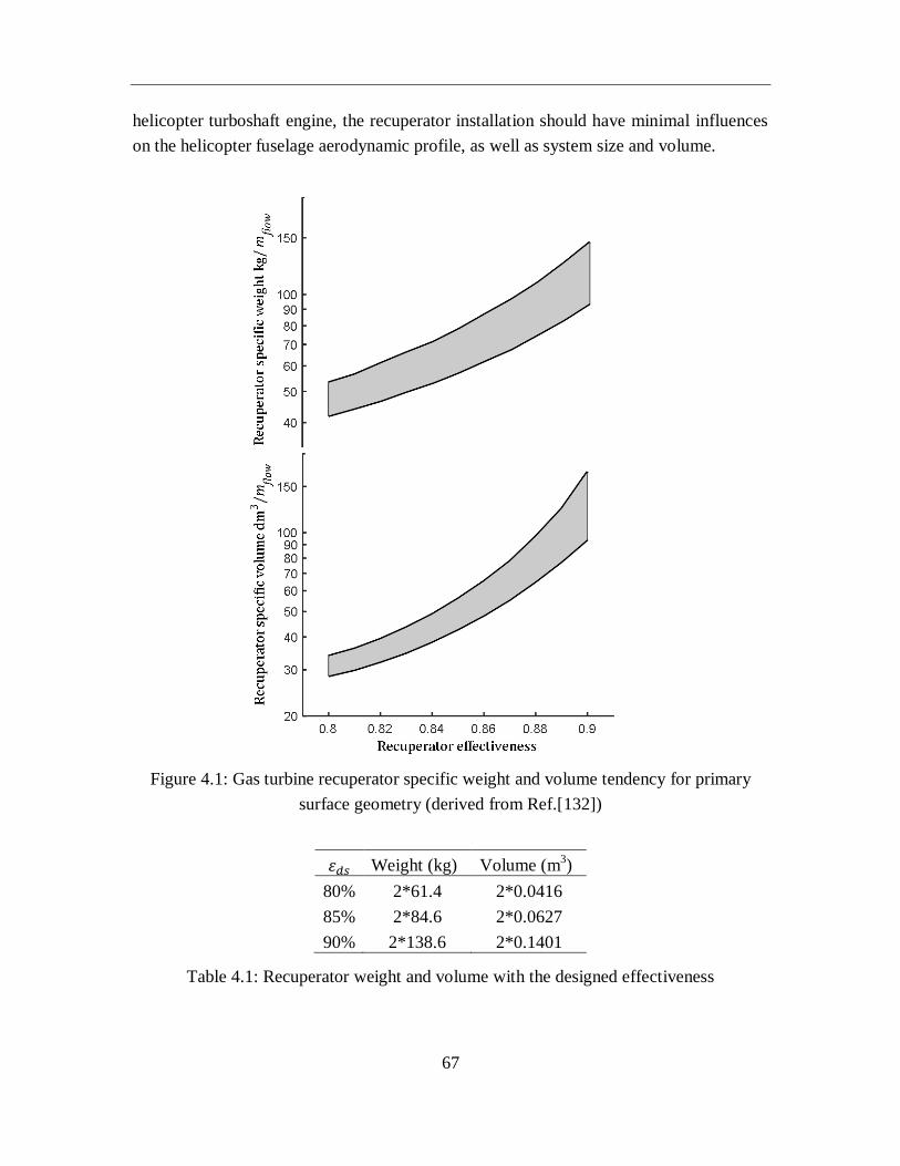
67
helicopter turboshaft engine, the recuperator installation should have minimal influences
on the helicopter fuselage aerodynamic profile, as well as system size and volume.
Figure 4.1: Gas turbine recuperator specific weight and volume tendency for primary
surface geometry (derived from Ref.[132])
휀𝑑𝑠 Weight (kg) Volume (m3)
80% 2*61.4 2*0.0416
85% 2*84.6 2*0.0627
90% 2*138.6 2*0.1401
Table 4.1: Recuperator weight and volume with the designed effectiveness
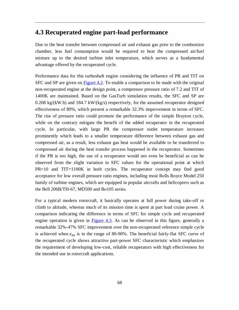
68
4.3 Recuperated engine part-load performance
Due to the heat transfer between compressed air and exhaust gas prior to the combustion
chamber, less fuel consumption would be required to heat the compressed air/fuel
mixture up to the desired turbine inlet temperature, which serves as a fundamental
advantage offered by the recuperated cycle.
Performance data for this turboshaft engine considering the influence of PR and TIT on
SFC and SP are given on Figure 4.2. To enable a comparison to be made with the original
non-recuperated engine at the design point, a compressor pressure ratio of 7.2 and TIT of
1400K are maintained. Based on the GasTurb simulation results, the SFC and SP are
0.268 kg/(kW.h) and 184.7 kW/(kg/s) respectively, for the assumed recuperator designed
effectiveness of 80%, which present a remarkable 32.3% improvement in terms of SFC.
The rise of pressure ratio could promote the performance of the simple Brayton cycle,
while on the contrary mitigate the benefit of the added recuperator in the recuperated
cycle. In particular, with large PR the compressor outlet temperature increases
prominently which leads to a smaller temperature difference between exhaust gas and
compressed air, as a result, less exhaust gas heat would be available to be transferred to
compressed air during the heat transfer process happened in the recuperator. Sometimes
if the PR is too high, the use of a recuperator would not even be beneficial as can be
observed from the slight variation in SFC values for the operational point at which
PR=10 and TIT=1100K in both cycles. The recuperator concept may find good
acceptance for low overall pressure ratio engines, including most Rolls Royce Model 250
family of turbine engines, which are equipped in popular aircrafts and helicopters such as
the Bell 206B/TH-67, MD500 and Bo105 series.
For a typical modern rotorcraft, it basically operates at full power during take-off or
climb to altitude, whereas much of its mission time is spent at part load cruise power. A
comparison indicating the difference in terms of SFC for simple cycle and recuperated
engine operation is given in Figure 4.3. As can be observed in this figure, generally a
remarkable 32%-47% SFC improvement over the non-recuperated reference simple cycle
is achieved when 휀𝑑𝑠 is in the range of 80-90%. The beneficial fairly-flat SFC curve of
the recuperated cycle shows attractive part-power SFC characteristic which emphasizes
the requirement of developing low-cost, reliable recuperators with high effectiveness for
the intended use in rotorcraft applications.
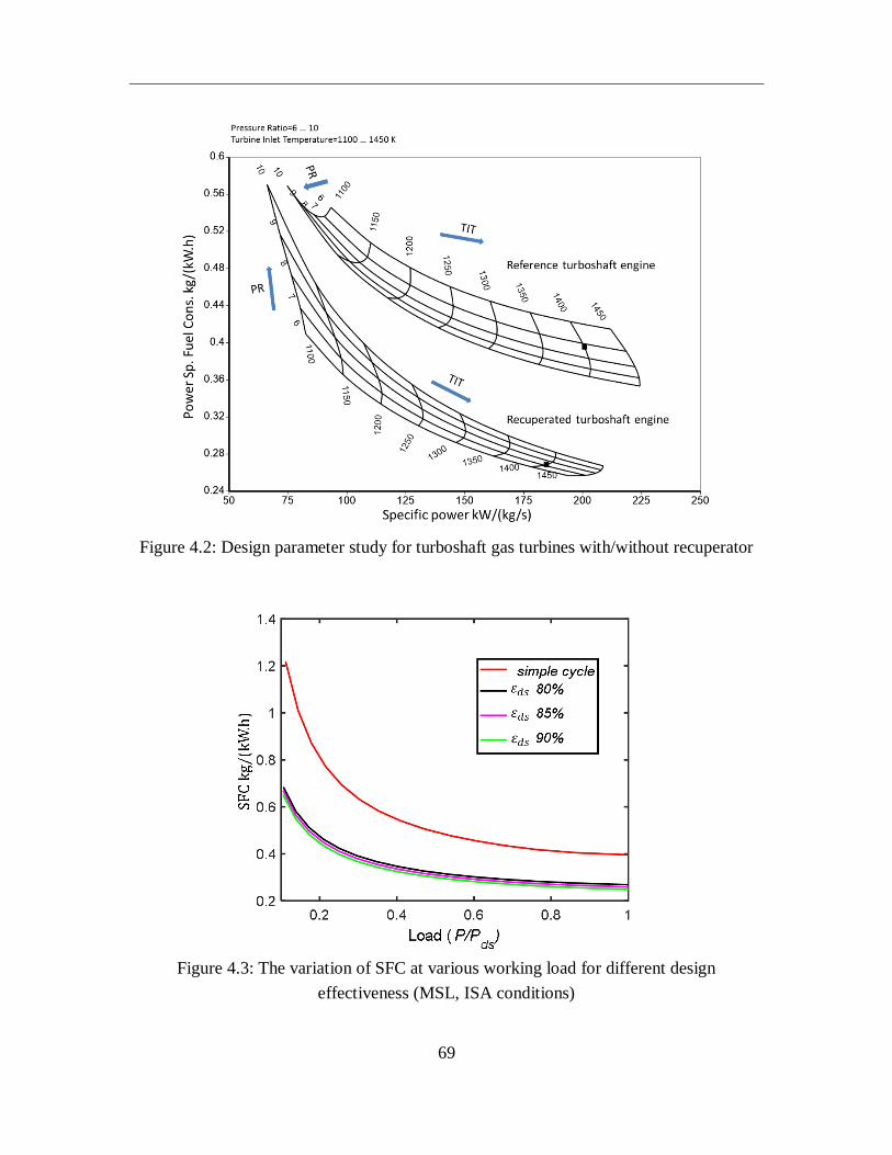
69
Figure 4.2: Design parameter study for turboshaft gas turbines with/without recuperator
Figure 4.3: The variation of SFC at various working load for different design
effectiveness (MSL, ISA conditions)
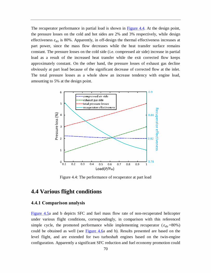
70
The recuperator performance in partial load is shown in Figure 4.4. At the design point,
the pressure losses on the cold and hot sides are 2% and 3% respectively, while design
effectiveness 휀𝑑𝑠 is 80%. Apparently, in off-design the thermal effectiveness increases at
part power, since the mass flow decreases while the heat transfer surface remains
constant. The pressure losses on the cold side (i.e. compressed air side) increase in partial
load as a result of the increased heat transfer while the exit corrected flow keeps
approximately constant. On the other hand, the pressure losses of exhaust gas decline
obviously at part load because of the significant decrease of corrected flow at the inlet.
The total pressure losses as a whole show an increase tendency with engine load,
amounting to 5% at the design point.
Figure 4.4: The performance of recuperator at part load
4.4 Various flight conditions
4.4.1 Comparison analysis
Figure 4.5a and b depicts SFC and fuel mass flow rate of non-recuperated helicopter
under various flight conditions, correspondingly, in comparison with this referenced
simple cycle, the promoted performance while implementing recuperator (휀𝑑𝑠 =80%)
could be obtained as well (see Figure 4.6a and b). Results presented are based on the
level flight, and are extended for two turboshaft engines based on the twin-engine
configuration. Apparently a significant SFC reduction and fuel economy promotion could
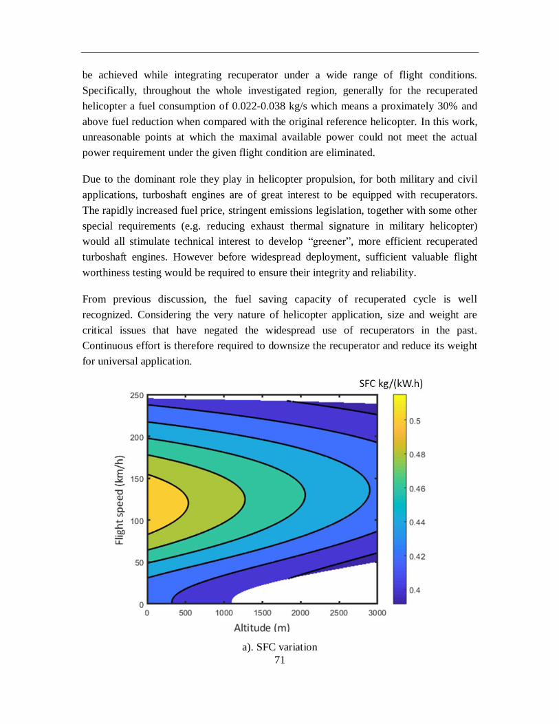
71
be achieved while integrating recuperator under a wide range of flight conditions.
Specifically, throughout the whole investigated region, generally for the recuperated
helicopter a fuel consumption of 0.022-0.038 kg/s which means a proximately 30% and
above fuel reduction when compared with the original reference helicopter. In this work,
unreasonable points at which the maximal available power could not meet the actual
power requirement under the given flight condition are eliminated.
Due to the dominant role they play in helicopter propulsion, for both military and civil
applications, turboshaft engines are of great interest to be equipped with recuperators.
The rapidly increased fuel price, stringent emissions legislation, together with some other
special requirements (e.g. reducing exhaust thermal signature in military helicopter)
would all stimulate technical interest to develop “greener”, more efficient recuperated
turboshaft engines. However before widespread deployment, sufficient valuable flight
worthiness testing would be required to ensure their integrity and reliability.
From previous discussion, the fuel saving capacity of recuperated cycle is well
recognized. Considering the very nature of helicopter application, size and weight are
critical issues that have negated the widespread use of recuperators in the past.
Continuous effort is therefore required to downsize the recuperator and reduce its weight
for universal application.
a). SFC variation
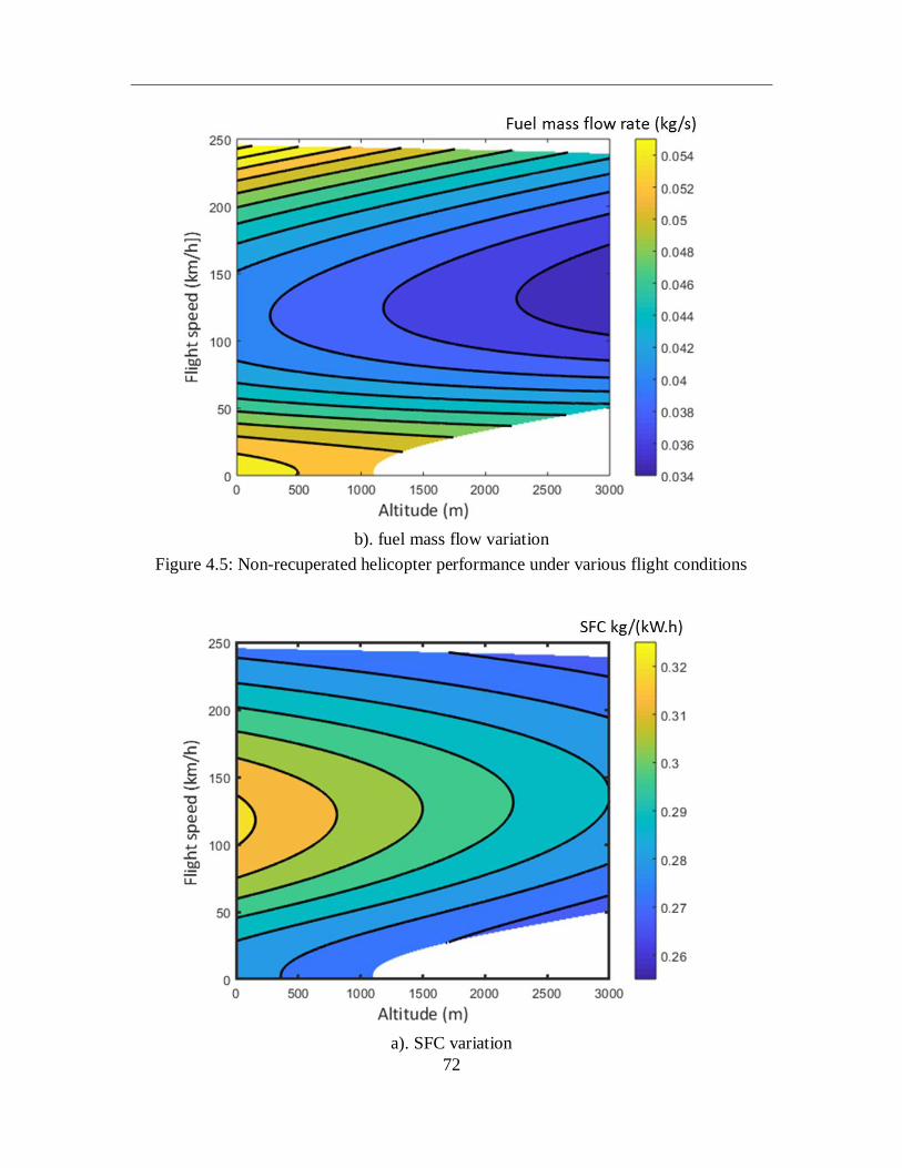
72
b). fuel mass flow variation
Figure 4.5: Non-recuperated helicopter performance under various flight conditions
a). SFC variation
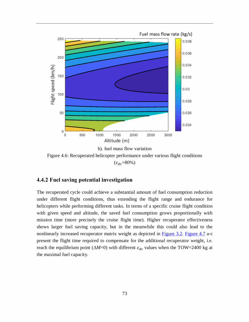
73
b). fuel mass flow variation
Figure 4.6: Recuperated helicopter performance under various flight conditions
(휀𝑑𝑠=80%)
4.4.2 Fuel saving potential investigation
The recuperated cycle could achieve a substantial amount of fuel consumption reduction
under different flight conditions, thus extending the flight range and endurance for
helicopters while performing different tasks. In terms of a specific cruise flight condition
with given speed and altitude, the saved fuel consumption grows proportionally with
mission time (more precisely the cruise flight time). Higher recuperator effectiveness
shows larger fuel saving capacity, but in the meanwhile this could also lead to the
nonlinearly increased recuperator matrix weight as depicted in Figure 3.2. Figure 4.7 a-c
present the flight time required to compensate for the additional recuperator weight, i.e.
reach the equilibrium point (∆M=0) with different 휀𝑑𝑠 values when the TOW=2400 kg at
the maximal fuel capacity.
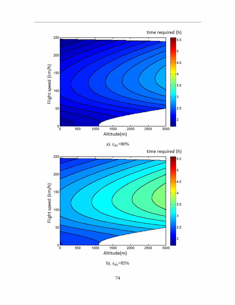
74
a). 휀𝑑𝑠=80%
b). 휀𝑑𝑠=85%
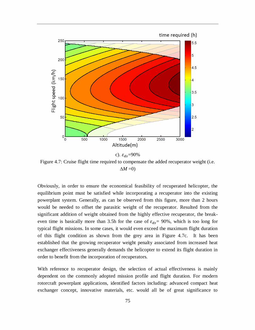
75
c). 휀𝑑𝑠=90%
Figure 4.7: Cruise flight time required to compensate the added recuperator weight (i.e.
∆M =0)
Obviously, in order to ensure the economical feasibility of recuperated helicopter, the
equilibrium point must be satisfied while incorporating a recuperator into the existing
powerplant system. Generally, as can be observed from this figure, more than 2 hours
would be needed to offset the parasitic weight of the recuperator. Resulted from the
significant addition of weight obtained from the highly effective recuperator, the break-
even time is basically more than 3.5h for the case of 휀𝑑𝑠= 90%, which is too long for
typical flight missions. In some cases, it would even exceed the maximum flight duration
of this flight condition as shown from the grey area in Figure 4.7c. It has been
established that the growing recuperator weight penalty associated from increased heat
exchanger effectiveness generally demands the helicopter to extend its flight duration in
order to benefit from the incorporation of recuperators.
With reference to recuperator design, the selection of actual effectiveness is mainly
dependent on the commonly adopted mission profile and flight duration. For modern
rotorcraft powerplant applications, identified factors including: advanced compact heat
exchanger concept, innovative materials, etc. would all be of great significance to
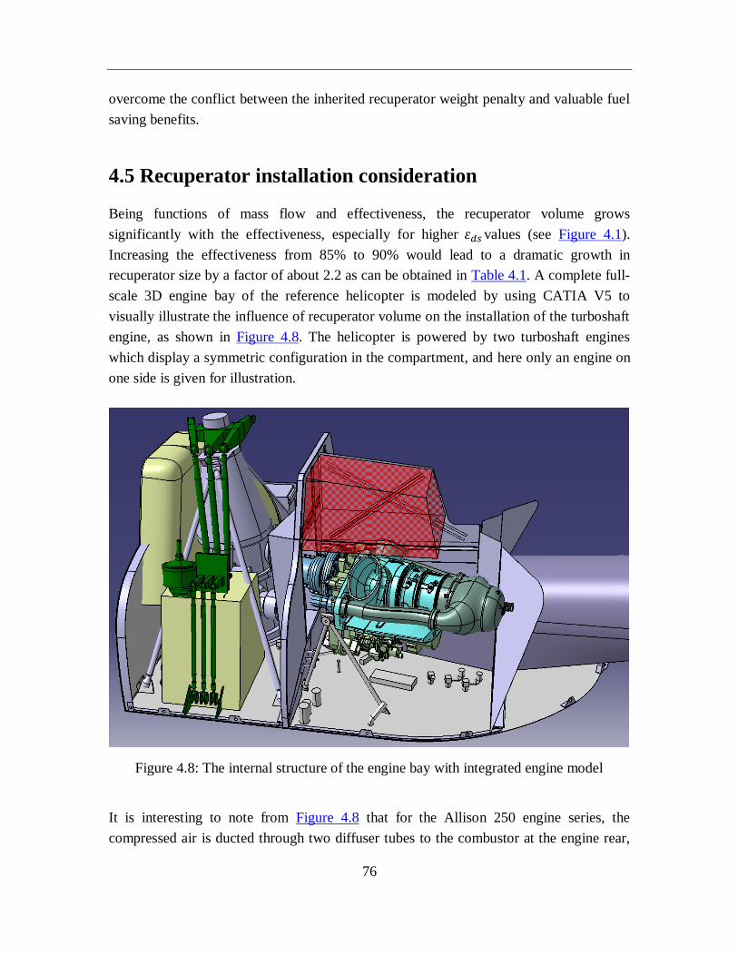
76
overcome the conflict between the inherited recuperator weight penalty and valuable fuel
saving benefits.
4.5 Recuperator installation consideration
Being functions of mass flow and effectiveness, the recuperator volume grows
significantly with the effectiveness, especially for higher 휀𝑑𝑠 values (see Figure 4.1).
Increasing the effectiveness from 85% to 90% would lead to a dramatic growth in
recuperator size by a factor of about 2.2 as can be obtained in Table 4.1. A complete full-
scale 3D engine bay of the reference helicopter is modeled by using CATIA V5 to
visually illustrate the influence of recuperator volume on the installation of the turboshaft
engine, as shown in Figure 4.8. The helicopter is powered by two turboshaft engines
which display a symmetric configuration in the compartment, and here only an engine on
one side is given for illustration.
Figure 4.8: The internal structure of the engine bay with integrated engine model
It is interesting to note from Figure 4.8 that for the Allison 250 engine series, the
compressed air is ducted through two diffuser tubes to the combustor at the engine rear,
77
after combustion the exhaust gas flows in a reversed direction to the turbine located
intermediate the combustor and compressor. Such configuration makes the investigated
turboshaft engine especially suitable to be retrofit to incorporate a high performance
recuperator without unduly changing the air flow path of the whole system. In the engine
compartment, above the engine unit it provides available space for the installation of
recuperator. Take 휀𝑑𝑠=85% as an example, the cube shaped recuperator configuration,
with a corresponding matrix volume of 0.0627 m3, is adopted using primary surface
geometry. Nevertheless, the potential installation space identified in red from Figure 4.8
offers an available volume of 0.043 m3 which is not sufficient to meet this size
requirement. Actually, this available space could only enable the incorporation of
recuperator with a maximum designed effectiveness of approximately 80% in this work.
The excessive weight and bulky size of early heat exchangers are some of major factors
that impede the wide acceptance of recuperated aeroengines, and therefore light weight,
compact volume and compatible gas flow paths are all deemed as necessary features
while developing candidate recuperators for future propulsion gas turbines.
It is accepted that meeting increasingly stricter future economic and environmental
requirements will inevitably have a profound impact on aeroengines’ design and
operation, which has also contributed to the current interest in developing high
performance heat exchangers in the aeroengine industry. For helicopter turboshaft
engines, the major advantage of the recuperated cycle over the conventional Brayton
cycle is the improved SFC at partial load, where the majority of the engine operating time
would be spent. Primarily due to the increased engine cost, weight and volume, as well as
reliability concerns, at present the recuperated helicopter has not yet come to fruition.
Novel compact heat exchangers with light weight, small volume and high effectiveness
are projected to improve rotorcraft performance with advanced materials and improved
manufacturing technologies.
4.6 Summary
In light of the previous researches on recuperator technology with respect to its
application to rotorcraft powerplants. Focus was primarily put on tubular recuperator with
a relatively low thermal effectiveness. Nowadays, primary surface recuperator would be
regarded as a promising candidate considering the current technology readiness on high
temperature heat exchanger.
78
For the purpose of this study, the integrated multidisciplinary rotorcraft simulation
framework has been further implemented to evaluate the potential of recuperated
helicopter turboshaft engine, adopting highly effective primary surface recuperator for a
higher level of thermal effectiveness, saying 80-90%. The improved part-load
performance of recuperated engine in contrast to the simple cycle counterpart is
investigated in detail, followed by the analysis and evaluation of fuel saving potential
under various flight conditions (with the flight speed of 0-250 km/h and altitude of 0-
3000 m). The impact of recuperator volume and potential installation are discussed as
well.
The obtained results suggest a considerable reduction in fuel burn and therefore have
great potential in enhancing the helicopter operational performance (e.g. rotorcraft range
and payload capability) while incorporating highly effective recuperators into rotorcraft
systems. However, it would not give favorable performance for short-term flight
duration, especially while conducting the flight at high altitude, as the fuel consumption
reduction of recuperated cycle during the whole mission is not sufficient to offset the
added parasitic weight of the recuperator.
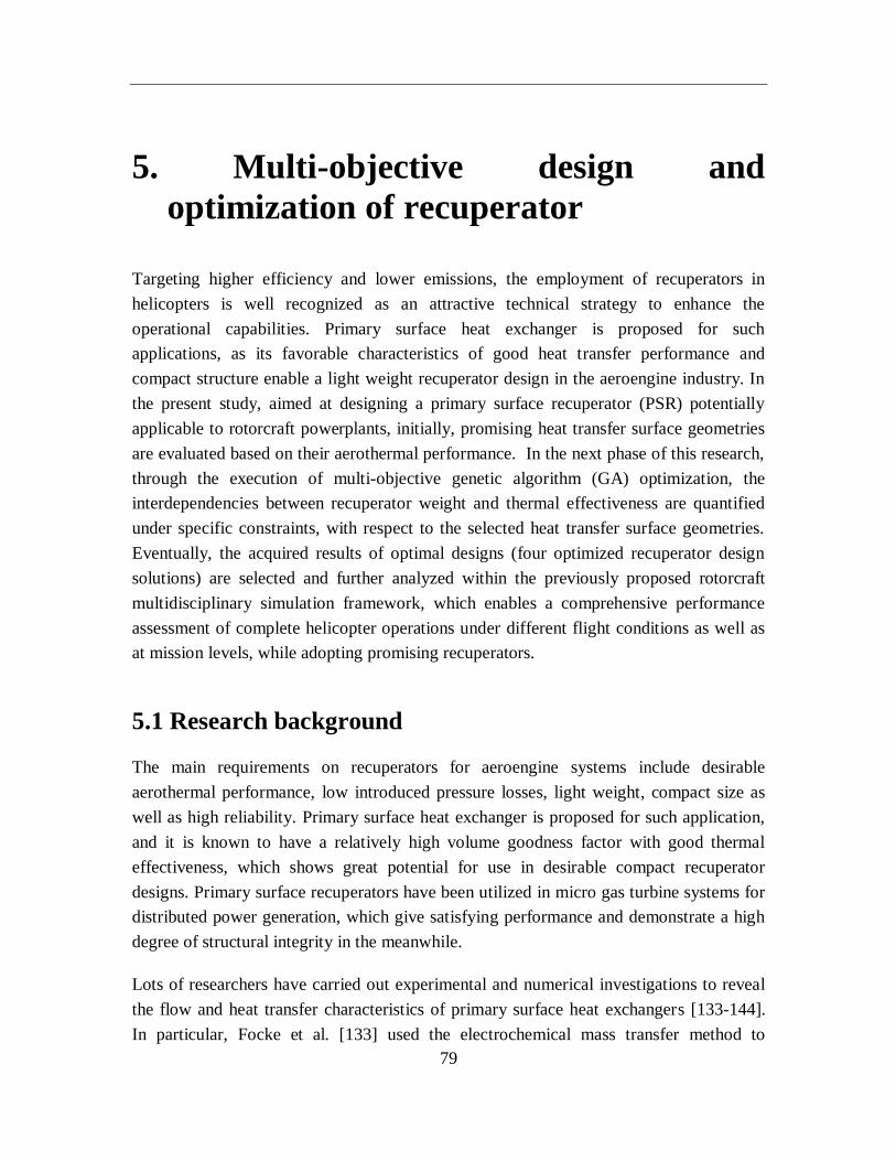
79
5. Multi-objective design and
optimization of recuperator
Targeting higher efficiency and lower emissions, the employment of recuperators in
helicopters is well recognized as an attractive technical strategy to enhance the
operational capabilities. Primary surface heat exchanger is proposed for such
applications, as its favorable characteristics of good heat transfer performance and
compact structure enable a light weight recuperator design in the aeroengine industry. In
the present study, aimed at designing a primary surface recuperator (PSR) potentially
applicable to rotorcraft powerplants, initially, promising heat transfer surface geometries
are evaluated based on their aerothermal performance. In the next phase of this research,
through the execution of multi-objective genetic algorithm (GA) optimization, the
interdependencies between recuperator weight and thermal effectiveness are quantified
under specific constraints, with respect to the selected heat transfer surface geometries.
Eventually, the acquired results of optimal designs (four optimized recuperator design
solutions) are selected and further analyzed within the previously proposed rotorcraft
multidisciplinary simulation framework, which enables a comprehensive performance
assessment of complete helicopter operations under different flight conditions as well as
at mission levels, while adopting promising recuperators.
5.1 Research background
The main requirements on recuperators for aeroengine systems include desirable
aerothermal performance, low introduced pressure losses, light weight, compact size as
well as high reliability. Primary surface heat exchanger is proposed for such application,
and it is known to have a relatively high volume goodness factor with good thermal
effectiveness, which shows great potential for use in desirable compact recuperator
designs. Primary surface recuperators have been utilized in micro gas turbine systems for
distributed power generation, which give satisfying performance and demonstrate a high
degree of structural integrity in the meanwhile.
Lots of researchers have carried out experimental and numerical investigations to reveal
the flow and heat transfer characteristics of primary surface heat exchangers [133-144].
In particular, Focke et al. [133] used the electrochemical mass transfer method to
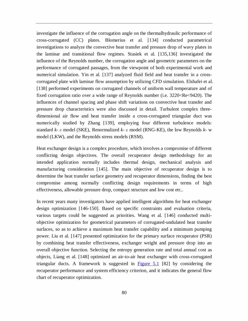
80
investigate the influence of the corrugation angle on the thermalhydraulic performance of
cross-corrugated (CC) plates. Blomerius et al. [134] conducted parametrical
investigations to analyze the convective heat transfer and pressure drop of wavy plates in
the laminar and transitional flow regimes. Stasiek et al. [135,136] investigated the
influence of the Reynolds number, the corrugation angle and geometric parameters on the
performance of corrugated passages, from the viewpoint of both experimental work and
numerical simulation. Yin et al. [137] analyzed fluid field and heat transfer in a cross-
corrugated plate with laminar flow assumption by utilizing CFD simulation. Elshafei et al.
[138] performed experiments on corrugated channels of uniform wall temperature and of
fixed corrugation ratio over a wide range of Reynolds number (i.e. 3220<Re<9420). The
influences of channel spacing and phase shift variations on convective heat transfer and
pressure drop characteristics were also discussed in detail. Turbulent complex three-
dimensional air flow and heat transfer inside a cross-corrugated triangular duct was
numerically studied by Zhang [139], employing four different turbulence models:
standard k- ε model (SKE), Renormalized k- ε model (RNG-KE), the low Reynolds k- w
model (LKW), and the Reynolds stress models (RSM).
Heat exchanger design is a complex procedure, which involves a compromise of different
conflicting design objectives. The overall recuperator design methodology for an
intended application normally includes thermal design, mechanical analysis and
manufacturing consideration [145]. The main objective of recuperator design is to
determine the heat transfer surface geometry and recuperator dimensions, finding the best
compromise among normally conflicting design requirements in terms of high
effectiveness, allowable pressure drop, compact structure and low cost etc..
In recent years many investigators have applied intelligent algorithms for heat exchanger
design optimization [146-150]. Based on specific constraints and evaluation criteria,
various targets could be suggested as priorities. Wang et al. [146] conducted multi-
objective optimization for geometrical parameters of corrugated-undulated heat transfer
surfaces, so as to achieve a maximum heat transfer capability and a minimum pumping
power. Liu et al. [147] presented optimization for the primary surface recuperator (PSR)
by combining heat transfer effectiveness, exchanger weight and pressure drop into an
overall objective function. Selecting the entropy generation rate and total annual cost as
objects, Liang et al. [148] optimized an air-to-air heat exchanger with cross-corrugated
triangular ducts. A framework is suggested in Figure 5.1 [82] by considering the
recuperator performance and system efficiency criterion, and it indicates the general flow
chart of recuperator optimization.
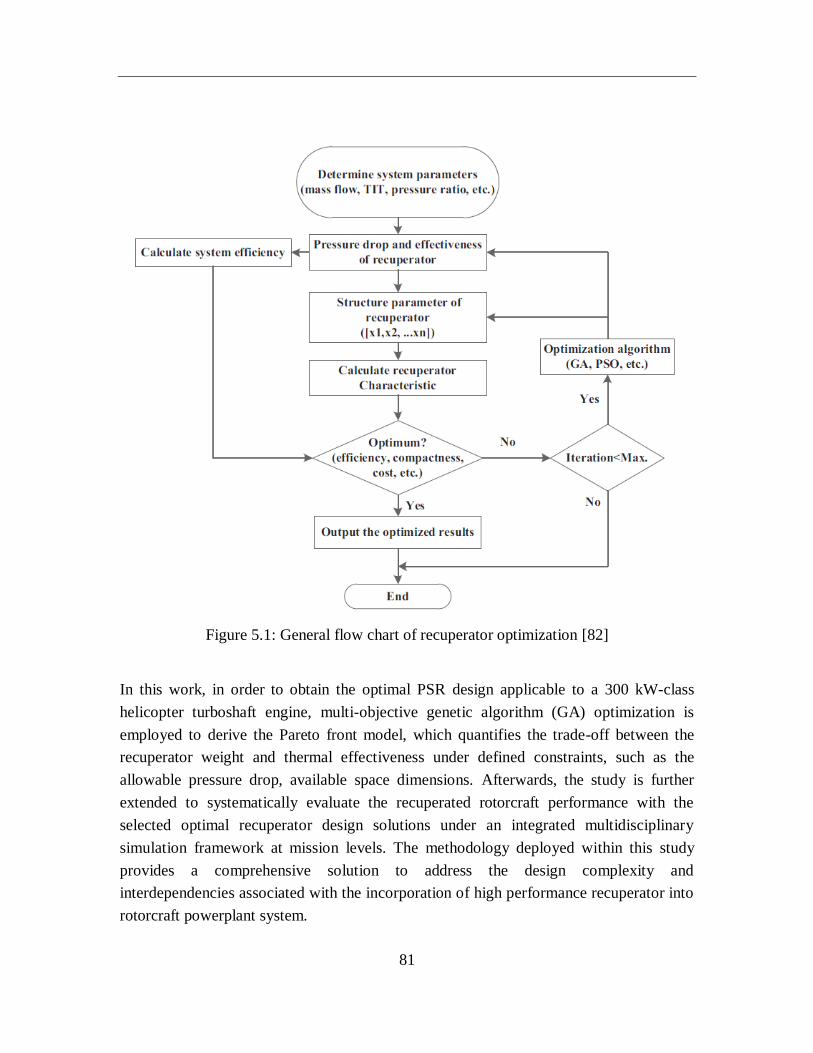
81
Figure 5.1: General flow chart of recuperator optimization [82]
In this work, in order to obtain the optimal PSR design applicable to a 300 kW-class
helicopter turboshaft engine, multi-objective genetic algorithm (GA) optimization is
employed to derive the Pareto front model, which quantifies the trade-off between the
recuperator weight and thermal effectiveness under defined constraints, such as the
allowable pressure drop, available space dimensions. Afterwards, the study is further
extended to systematically evaluate the recuperated rotorcraft performance with the
selected optimal recuperator design solutions under an integrated multidisciplinary
simulation framework at mission levels. The methodology deployed within this study
provides a comprehensive solution to address the design complexity and
interdependencies associated with the incorporation of high performance recuperator into
rotorcraft powerplant system.
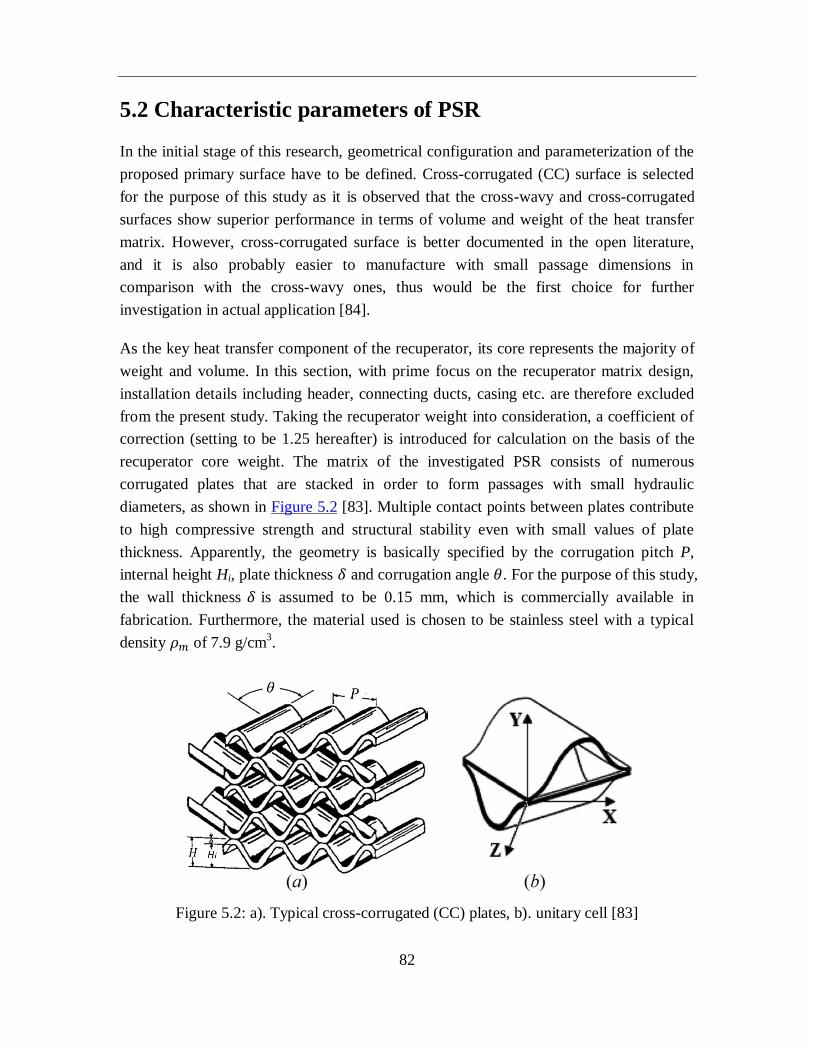
82
5.2 Characteristic parameters of PSR
In the initial stage of this research, geometrical configuration and parameterization of the
proposed primary surface have to be defined. Cross-corrugated (CC) surface is selected
for the purpose of this study as it is observed that the cross-wavy and cross-corrugated
surfaces show superior performance in terms of volume and weight of the heat transfer
matrix. However, cross-corrugated surface is better documented in the open literature,
and it is also probably easier to manufacture with small passage dimensions in
comparison with the cross-wavy ones, thus would be the first choice for further
investigation in actual application [84].
As the key heat transfer component of the recuperator, its core represents the majority of
weight and volume. In this section, with prime focus on the recuperator matrix design,
installation details including header, connecting ducts, casing etc. are therefore excluded
from the present study. Taking the recuperator weight into consideration, a coefficient of
correction (setting to be 1.25 hereafter) is introduced for calculation on the basis of the
recuperator core weight. The matrix of the investigated PSR consists of numerous
corrugated plates that are stacked in order to form passages with small hydraulic
diameters, as shown in Figure 5.2 [83]. Multiple contact points between plates contribute
to high compressive strength and structural stability even with small values of plate
thickness. Apparently, the geometry is basically specified by the corrugation pitch P,
internal height Hi, plate thickness 𝛿 and corrugation angle 𝜃. For the purpose of this study,
the wall thickness 𝛿 is assumed to be 0.15 mm, which is commercially available in
fabrication. Furthermore, the material used is chosen to be stainless steel with a typical
density 𝜌𝑚 of 7.9 g/cm3.
Figure 5.2: a). Typical cross-corrugated (CC) plates, b). unitary cell [83]
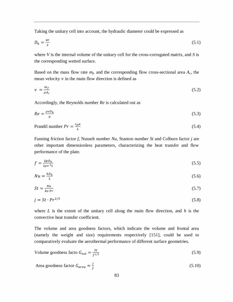
83
Taking the unitary cell into account, the hydraulic diameter could be expressed as
𝐷ℎ =4𝑉
𝑆 (5.1)
where V is the internal volume of the unitary cell for the cross-corrugated matrix, and S is
the corresponding wetted surface.
Based on the mass flow rate mf, and the corresponding flow cross-sectional area Ac, the
mean velocity 𝜈 in the main flow direction is defined as
𝜈 =𝑚𝑓
𝜌𝐴𝑐 (5.2)
Accordingly, the Reynolds number Re is calculated out as
𝑅𝑒 =𝜌𝜈𝐷ℎ
𝜇 (5.3)
Prandtl number 𝑃𝑟 =𝑐𝑝𝜇
λ (5.4)
Fanning friction factor f, Nusselt number Nu, Stanton number St and Colburn factor j are
other important dimensionless parameters, characterizing the heat transfer and flow
performance of the plate.
𝑓 =∆𝑝𝐷ℎ
2𝜌𝜈 2𝐿 (5.5)
𝑁𝑢 =ℎ𝐷ℎ
λ (5.6)
𝑆𝑡 =𝑁𝑢
𝑅𝑒∙𝑃𝑟 (5.7)
𝑗 = 𝑆𝑡 ∙ 𝑃𝑟2/3 (5.8)
where L is the extent of the unitary cell along the main flow direction, and h is the
convective heat transfer coefficient.
The volume and area goodness factors, which indicate the volume and frontal area
(namely the weight and size) requirements respectively [151], could be used to
comparatively evaluate the aerothermal performance of different surface geometries.
Volume goodness facto 𝐺𝑣𝑜𝑙 =𝑆𝑡
𝑓1/3 (5.9)
Area goodness factor 𝐺𝑎𝑟𝑒𝑎 =𝑗
𝑓 (5.10)
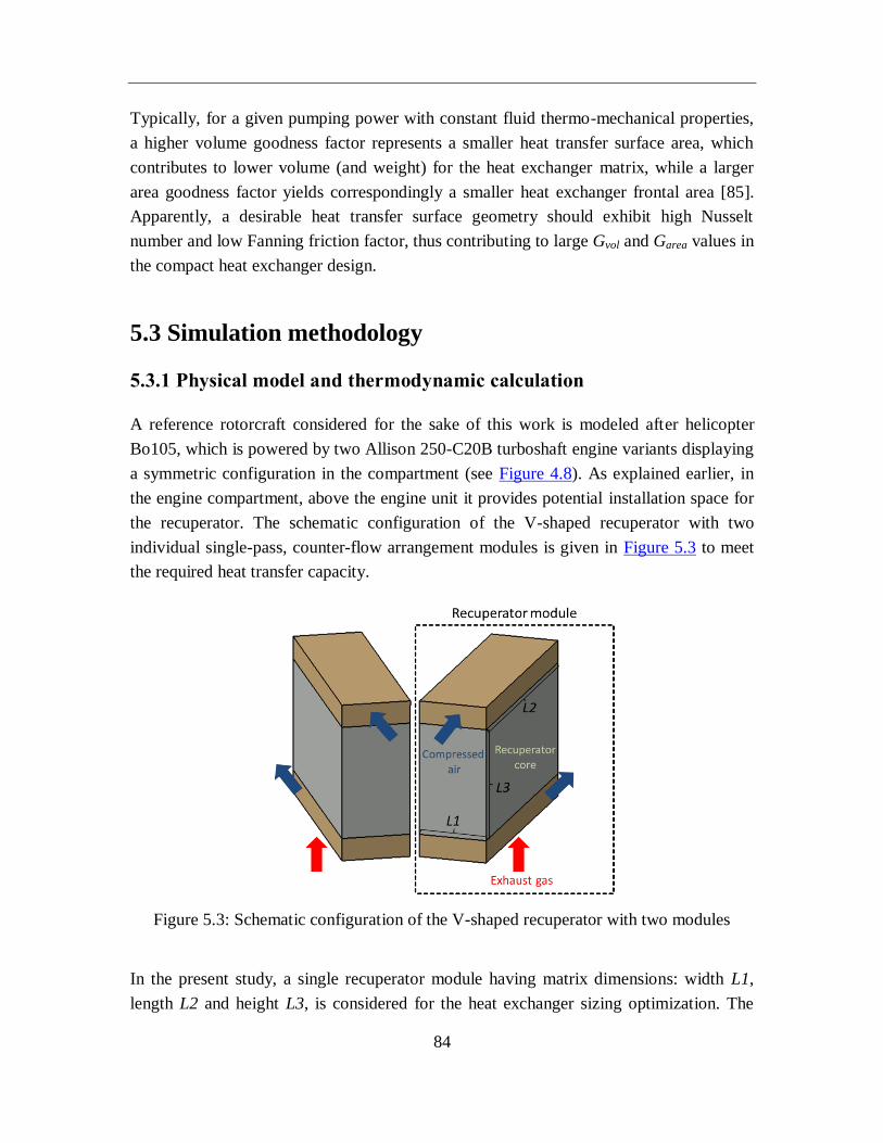
84
Typically, for a given pumping power with constant fluid thermo-mechanical properties,
a higher volume goodness factor represents a smaller heat transfer surface area, which
contributes to lower volume (and weight) for the heat exchanger matrix, while a larger
area goodness factor yields correspondingly a smaller heat exchanger frontal area [85].
Apparently, a desirable heat transfer surface geometry should exhibit high Nusselt
number and low Fanning friction factor, thus contributing to large Gvol and Garea values in
the compact heat exchanger design.
5.3 Simulation methodology
5.3.1 Physical model and thermodynamic calculation
A reference rotorcraft considered for the sake of this work is modeled after helicopter
Bo105, which is powered by two Allison 250-C20B turboshaft engine variants displaying
a symmetric configuration in the compartment (see Figure 4.8). As explained earlier, in
the engine compartment, above the engine unit it provides potential installation space for
the recuperator. The schematic configuration of the V-shaped recuperator with two
individual single-pass, counter-flow arrangement modules is given in Figure 5.3 to meet
the required heat transfer capacity.
Figure 5.3: Schematic configuration of the V-shaped recuperator with two modules
In the present study, a single recuperator module having matrix dimensions: width L1,
length L2 and height L3, is considered for the heat exchanger sizing optimization. The
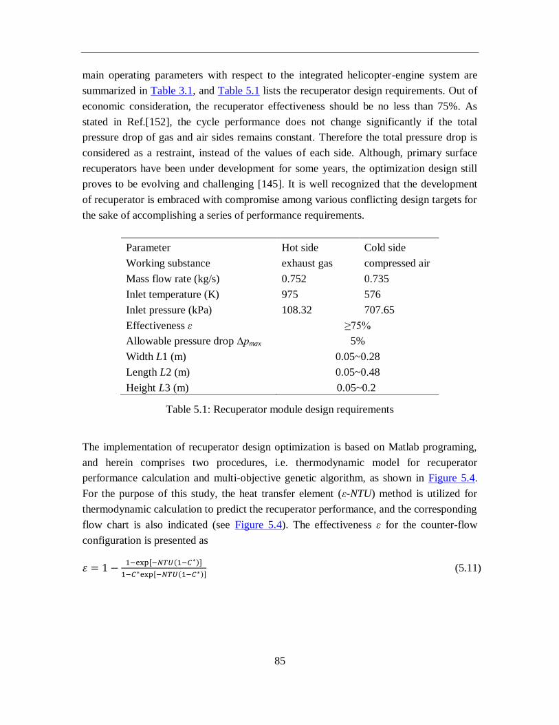
85
main operating parameters with respect to the integrated helicopter-engine system are
summarized in Table 3.1, and Table 5.1 lists the recuperator design requirements. Out of
economic consideration, the recuperator effectiveness should be no less than 75%. As
stated in Ref.[152], the cycle performance does not change significantly if the total
pressure drop of gas and air sides remains constant. Therefore the total pressure drop is
considered as a restraint, instead of the values of each side. Although, primary surface
recuperators have been under development for some years, the optimization design still
proves to be evolving and challenging [145]. It is well recognized that the development
of recuperator is embraced with compromise among various conflicting design targets for
the sake of accomplishing a series of performance requirements.
Parameter Hot side Cold side
Working substance exhaust gas compressed air
Mass flow rate (kg/s) 0.752 0.735
Inlet temperature (K) 975 576
Inlet pressure (kPa) 108.32 707.65
Effectiveness ε ≥75%
Allowable pressure drop ∆pmax 5%
Width L1 (m) 0.05~0.28
Length L2 (m) 0.05~0.48
Height L3 (m) 0.05~0.2
Table 5.1: Recuperator module design requirements
The implementation of recuperator design optimization is based on Matlab programing,
and herein comprises two procedures, i.e. thermodynamic model for recuperator
performance calculation and multi-objective genetic algorithm, as shown in Figure 5.4.
For the purpose of this study, the heat transfer element (ε-NTU) method is utilized for
thermodynamic calculation to predict the recuperator performance, and the corresponding
flow chart is also indicated (see Figure 5.4). The effectiveness ε for the counter-flow
configuration is presented as
휀 = 1 −1−exp[−𝑁𝑇𝑈(1−𝐶∗)]
1−𝐶∗exp[−𝑁𝑇𝑈(1−𝐶∗)] (5.11)
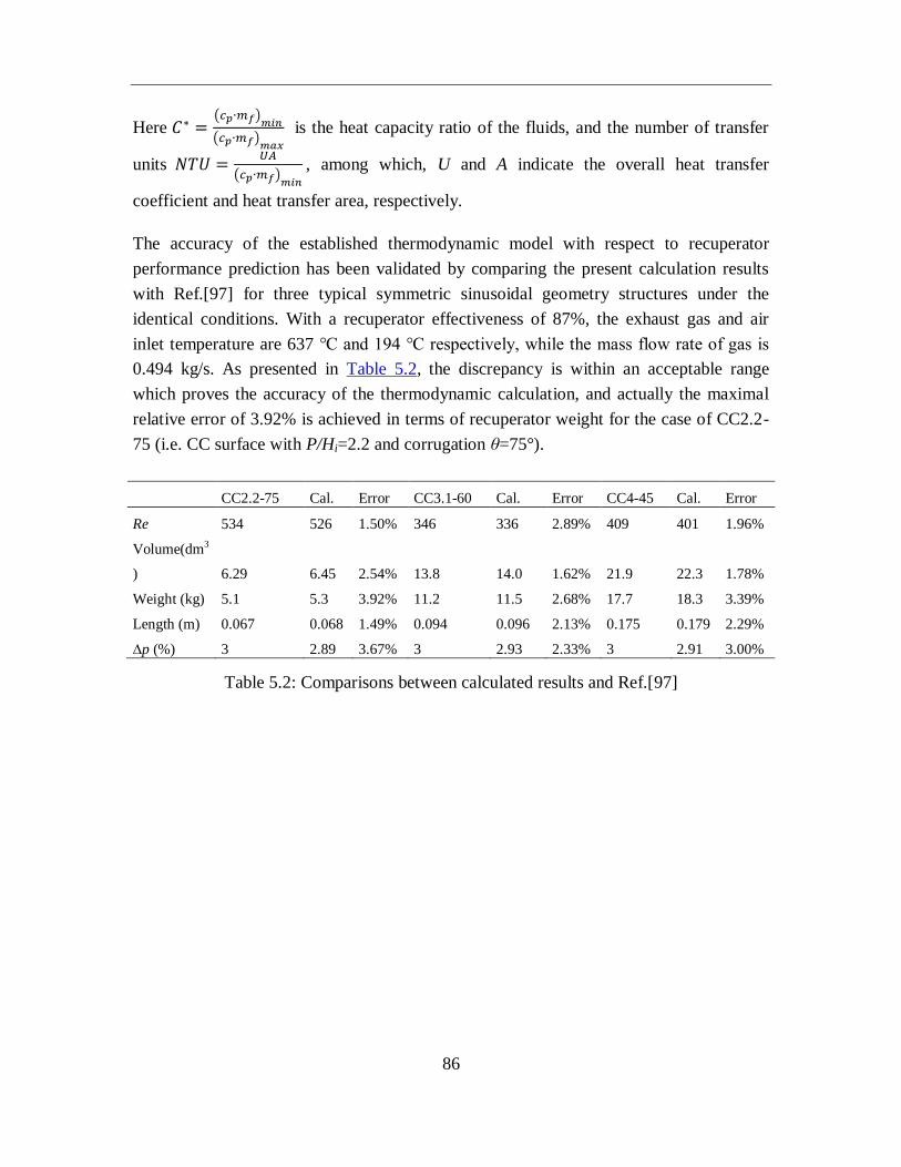
86
Here 𝐶∗ =(𝑐𝑝∙𝑚𝑓)
𝑚𝑖𝑛
(𝑐𝑝∙𝑚𝑓)𝑚𝑎𝑥
is the heat capacity ratio of the fluids, and the number of transfer
units 𝑁𝑇𝑈 =𝑈𝐴
(𝑐𝑝∙𝑚𝑓)𝑚𝑖𝑛
, among which, U and A indicate the overall heat transfer
coefficient and heat transfer area, respectively.
The accuracy of the established thermodynamic model with respect to recuperator
performance prediction has been validated by comparing the present calculation results
with Ref.[97] for three typical symmetric sinusoidal geometry structures under the
identical conditions. With a recuperator effectiveness of 87%, the exhaust gas and air
inlet temperature are 637 ℃ and 194 ℃ respectively, while the mass flow rate of gas is
0.494 kg/s. As presented in Table 5.2, the discrepancy is within an acceptable range
which proves the accuracy of the thermodynamic calculation, and actually the maximal
relative error of 3.92% is achieved in terms of recuperator weight for the case of CC2.2-
75 (i.e. CC surface with P/Hi=2.2 and corrugation θ=75°).
CC2.2-75 Cal. Error CC3.1-60 Cal. Error CC4-45 Cal. Error
Re 534 526 1.50% 346 336 2.89% 409 401 1.96%
Volume(dm3
) 6.29 6.45 2.54% 13.8 14.0 1.62% 21.9 22.3 1.78%
Weight (kg) 5.1 5.3 3.92% 11.2 11.5 2.68% 17.7 18.3 3.39%
Length (m) 0.067 0.068 1.49% 0.094 0.096 2.13% 0.175 0.179 2.29%
∆p (%) 3 2.89 3.67% 3 2.93 2.33% 3 2.91 3.00%
Table 5.2: Comparisons between calculated results and Ref.[97]
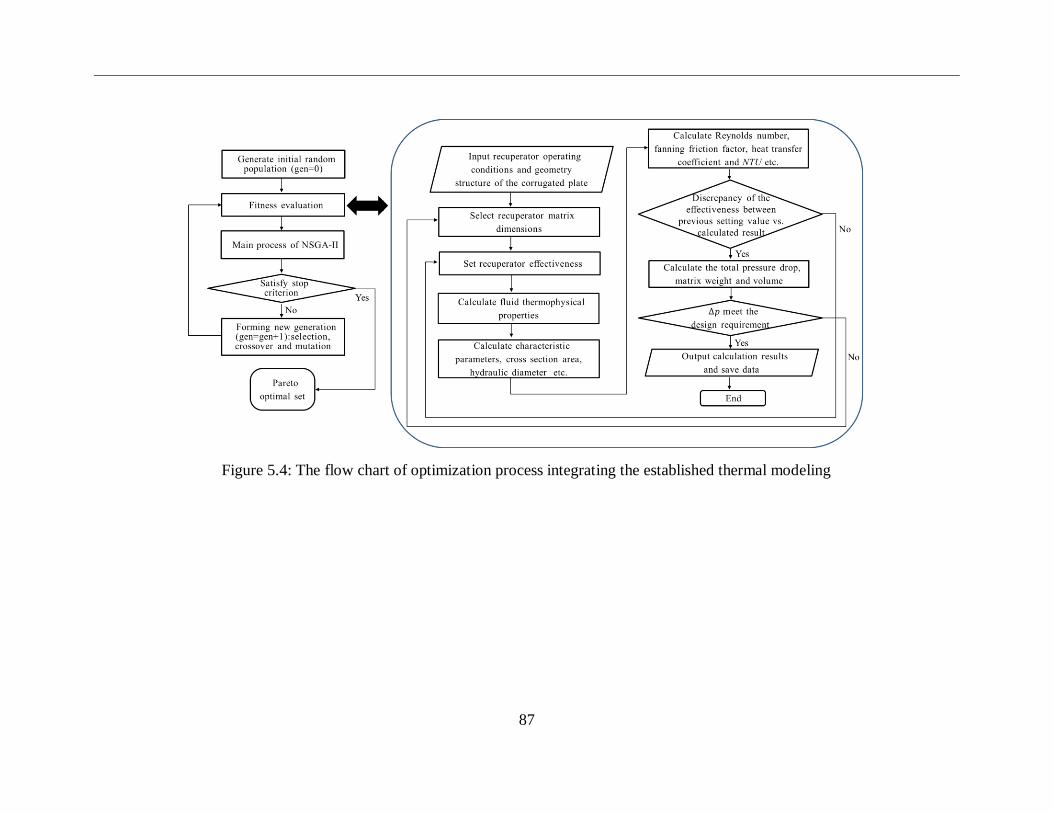
87
Figure 5.4: The flow chart of optimization process integrating the established thermal modeling
88
5.3.2 Multi-objective genetic algorithm optimization
The actual design of recuperator in the field of thermal engineering involve simultaneous
optimizations of multiple objectives, since various factors could be pursued as priorities,
such as weight, volume, heat transfer performance. By the very nature of this particular
application for aeroengines, the basic recuperator design requirements are light weight
(hence reducing size) and high effectiveness with allowable pressure drop. Resulting
from the absence of welding or brazing processes, the material quantity, which relates to
the recuperator weight directly, would be the primary factor that affects the final cost.
The goal of multi-objective optimization is to obtain the best compromise solutions
among different conflicting criterions [149].
The mathematical expression of a typical multi-objective optimization problem would be
given as
[𝑓1(𝑋), 𝑓2(𝑋), … … , 𝑓𝑘(𝑋)]𝑚𝑖𝑛
where variables 𝑋 = {𝑥1, 𝑥2, … … , 𝑥𝑗} subject to limitations
𝑔𝑚(𝑋) ≤ 0, 𝑚 = 1,2, …
ℎ𝑛(𝑋) = 0, 𝑛 = 1,2, …
The classical approach to solve the multi-objective optimization problem is to assign a
so-called weighting parameter wi to every single objective, thus obtaining an overall
objective function, i.e.
Min 𝐹(𝑋) = ∑ 𝑤𝑖𝑓𝑖𝑘𝑖=1 (𝑋) (here ∑ 𝑤𝑖 = 1) (5.12)
The inherent disadvantage of this methodology is that the final optimization results
depend strongly on the selection of weighting parameters, and would vary significantly
for different weighting parameter combinations. When a complicated multi-objective
optimization engineering problem is performed, the objectives under consideration are
generally in conflict with one another, and in most cases, it is hence impractical to find a
solution that simultaneously provides the optimal performance in terms of every single
optimization item. A reasonable approach is to analyze a set of potential optimal
solutions, each of which satisfies the objective functions at an acceptable level without
89
being dominated by any other feasible solution. Based on the theory of Pareto optimality,
solution A dominates solution B, if and only if,
(∀𝑖: 𝑓𝑖 (𝐴) ≤ 𝑓𝑖 (𝐵)) ∩ (∃𝑗: 𝑓𝑗(𝐴) < 𝑓𝑗(𝐵))
In that way, all non-dominated solutions or Pareto front, represent the best trade-off
between the involved objective functions, which means it is impractical to obtain a better
solution for one objective without worsening the others, as these requirements are mostly
inconsistent with one another.
In this study, Non-dominated Sorting Genetic Algorithms (NSGA-II) [153] is utilized to
attain these conflicting goals under the defined constraints, as presented in Figure 5.4.
Inspired by Charles Darwin’s theory of natural evolution, which could be summarized as
survival of the fittest, the genetic algorithm (GA) is a powerful tool in many real-life
problems according to the specified objectives under defined constraints. The procedure
could be shortly descripted as follows: different design variables are encoded into
corresponding binary strings, and these binary strings are subsequently grouped into a
long string, which represents an individual. Each individual is assigned a fitness value
based on its performance under the given environment. New generation of solutions, so
called child individuals are produced through the process of survival selection, crossover
and mutation between fit parent individuals. After several generations the algorithm
would converge to present optimal results.
In our calculation, a population size of 50 has been chosen, and the evolution is
controlled to be within 400 generations, besides that, the stall generations are set to be
150, which means the algorithm would also be terminated if the average change in the
spread of the Pareto front over 150 generations is less than function tolerance (i.e. 10-3
).
The conflicting objectives of recuperator weight penalty and associated thermal
effectiveness should be optimized simultaneously according to the design constraints as
presented in Table 5.1. With regards to the investigated multi-objective optimization
problem, the Pareto optimal set would be finally obtained, among which the best
compromise solution could be found, and potential recuperator designs are suggested.
5.3.3 Multidisciplinary simulation framework
Apart from the aforementioned optimization strategy for recuperator design, the present
work also requires the deployment of integrated rotorcraft simulation framework which
90
involves multidisciplinary knowledge including helicopter flight dynamics, turboshaft
engine performance and flight mission analysis etc., so as to systematically evaluate the
performance of the proposed recuperator on the whole rotorcraft powerplant under
different flight conditions.
As shown in Figure 5.5, the overall methodology combines the established
multidisciplinary rotorcraft simulation framework with the employment of recuperator
multi-objective genetic algorithm optimization. The aero-thermal performance of various
heat transfer surface geometries could be comparatively evaluated in terms of the volume
and area goodness factors Gvol and Garea, and promising candidates are then selected for
further geometry parameters and recuperator sizing optimization. Aimed at the
maximization of recuperator effectiveness and minimization of the corresponding weight,
and a set of multiple optimal solutions, namely Pareto optimal solutions would be
attained quantifying the interrelationship and trade-off between these two confliction
under specified limitations, e.g., thermal duty, spatial constraints. The recuperator
information including weight, volume, operating performance (designed effectiveness,
pressure drop, etc.) would be achieved based on multi-optimization processes. Acquired
results of optimal recuperator designs could be subsequently applied for mission
investigation targeting realistic helicopter operations within the established rotorcraft
multidisciplinary simulation framework.
With primary emphasis placed on the improvement of helicopter engine performance and
operational benefits arising from the implementation of recuperator, the scope of this
work is to further extend the integrated rotorcraft multidisciplinary simulation framework
through the employment of multi-objective GA optimization for recuperator design,
targeting at finding high performance heat exchangers potentially applicable to rotorcraft
powerplants. As a computationally efficient and cost-effective tool, the overall approach
can be effectively extended and applied to conduct multidisciplinary design and
optimization for recuperated rotorcraft at mission levels.
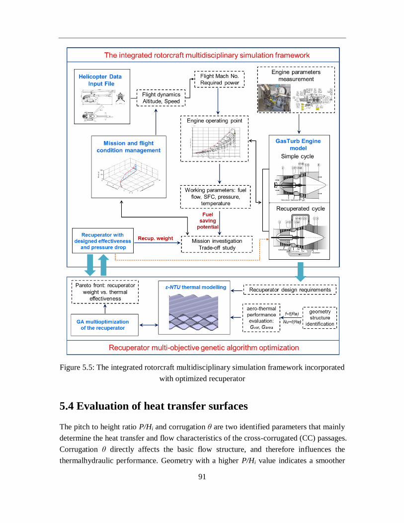
91
Figure 5.5: The integrated rotorcraft multidisciplinary simulation framework incorporated
with optimized recuperator
5.4 Evaluation of heat transfer surfaces
The pitch to height ratio P/Hi and corrugation θ are two identified parameters that mainly
determine the heat transfer and flow characteristics of the cross-corrugated (CC) passages.
Corrugation θ directly affects the basic flow structure, and therefore influences the
thermalhydraulic performance. Geometry with a higher P/Hi value indicates a smoother
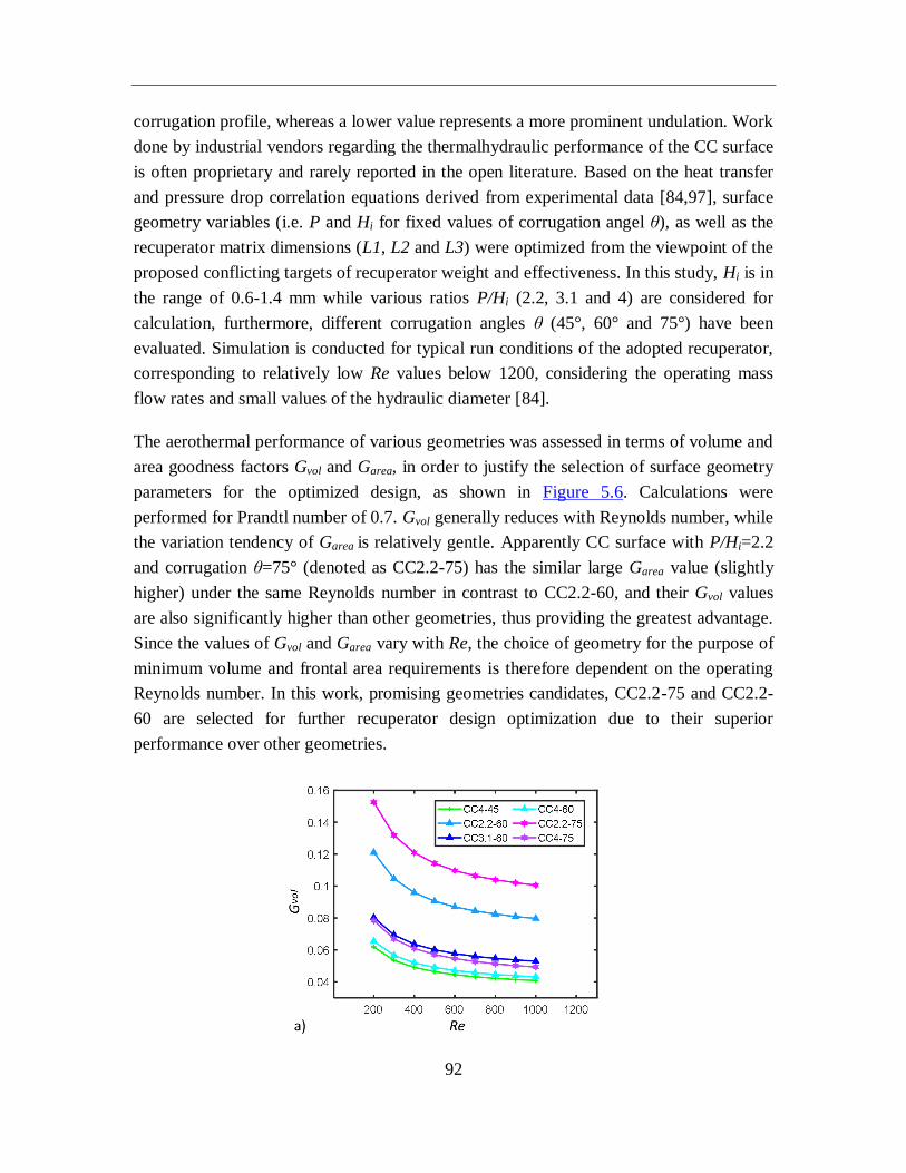
92
corrugation profile, whereas a lower value represents a more prominent undulation. Work
done by industrial vendors regarding the thermalhydraulic performance of the CC surface
is often proprietary and rarely reported in the open literature. Based on the heat transfer
and pressure drop correlation equations derived from experimental data [84,97], surface
geometry variables (i.e. P and Hi for fixed values of corrugation angel θ), as well as the
recuperator matrix dimensions (L1, L2 and L3) were optimized from the viewpoint of the
proposed conflicting targets of recuperator weight and effectiveness. In this study, Hi is in
the range of 0.6-1.4 mm while various ratios P/Hi (2.2, 3.1 and 4) are considered for
calculation, furthermore, different corrugation angles θ (45°, 60° and 75°) have been
evaluated. Simulation is conducted for typical run conditions of the adopted recuperator,
corresponding to relatively low Re values below 1200, considering the operating mass
flow rates and small values of the hydraulic diameter [84].
The aerothermal performance of various geometries was assessed in terms of volume and
area goodness factors Gvol and Garea, in order to justify the selection of surface geometry
parameters for the optimized design, as shown in Figure 5.6. Calculations were
performed for Prandtl number of 0.7. Gvol generally reduces with Reynolds number, while
the variation tendency of Garea is relatively gentle. Apparently CC surface with P/Hi=2.2
and corrugation θ=75° (denoted as CC2.2-75) has the similar large Garea value (slightly
higher) under the same Reynolds number in contrast to CC2.2-60, and their Gvol values
are also significantly higher than other geometries, thus providing the greatest advantage.
Since the values of Gvol and Garea vary with Re, the choice of geometry for the purpose of
minimum volume and frontal area requirements is therefore dependent on the operating
Reynolds number. In this work, promising geometries candidates, CC2.2-75 and CC2.2-
60 are selected for further recuperator design optimization due to their superior
performance over other geometries.
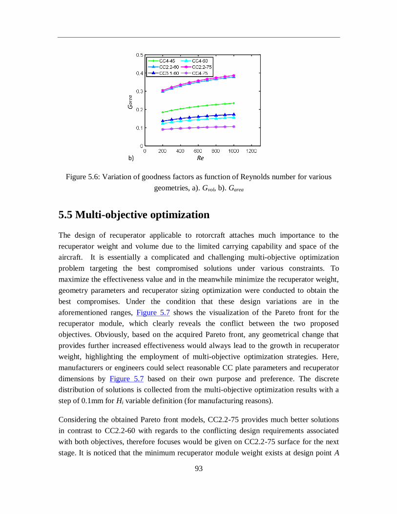
93
Figure 5.6: Variation of goodness factors as function of Reynolds number for various
geometries, a). Gvol, b). Garea
5.5 Multi-objective optimization
The design of recuperator applicable to rotorcraft attaches much importance to the
recuperator weight and volume due to the limited carrying capability and space of the
aircraft. It is essentially a complicated and challenging multi-objective optimization
problem targeting the best compromised solutions under various constraints. To
maximize the effectiveness value and in the meanwhile minimize the recuperator weight,
geometry parameters and recuperator sizing optimization were conducted to obtain the
best compromises. Under the condition that these design variations are in the
aforementioned ranges, Figure 5.7 shows the visualization of the Pareto front for the
recuperator module, which clearly reveals the conflict between the two proposed
objectives. Obviously, based on the acquired Pareto front, any geometrical change that
provides further increased effectiveness would always lead to the growth in recuperator
weight, highlighting the employment of multi-objective optimization strategies. Here,
manufacturers or engineers could select reasonable CC plate parameters and recuperator
dimensions by Figure 5.7 based on their own purpose and preference. The discrete
distribution of solutions is collected from the multi-objective optimization results with a
step of 0.1mm for Hi variable definition (for manufacturing reasons).
Considering the obtained Pareto front models, CC2.2-75 provides much better solutions
in contrast to CC2.2-60 with regards to the conflicting design requirements associated
with both objectives, therefore focuses would be given on CC2.2-75 surface for the next
stage. It is noticed that the minimum recuperator module weight exists at design point A
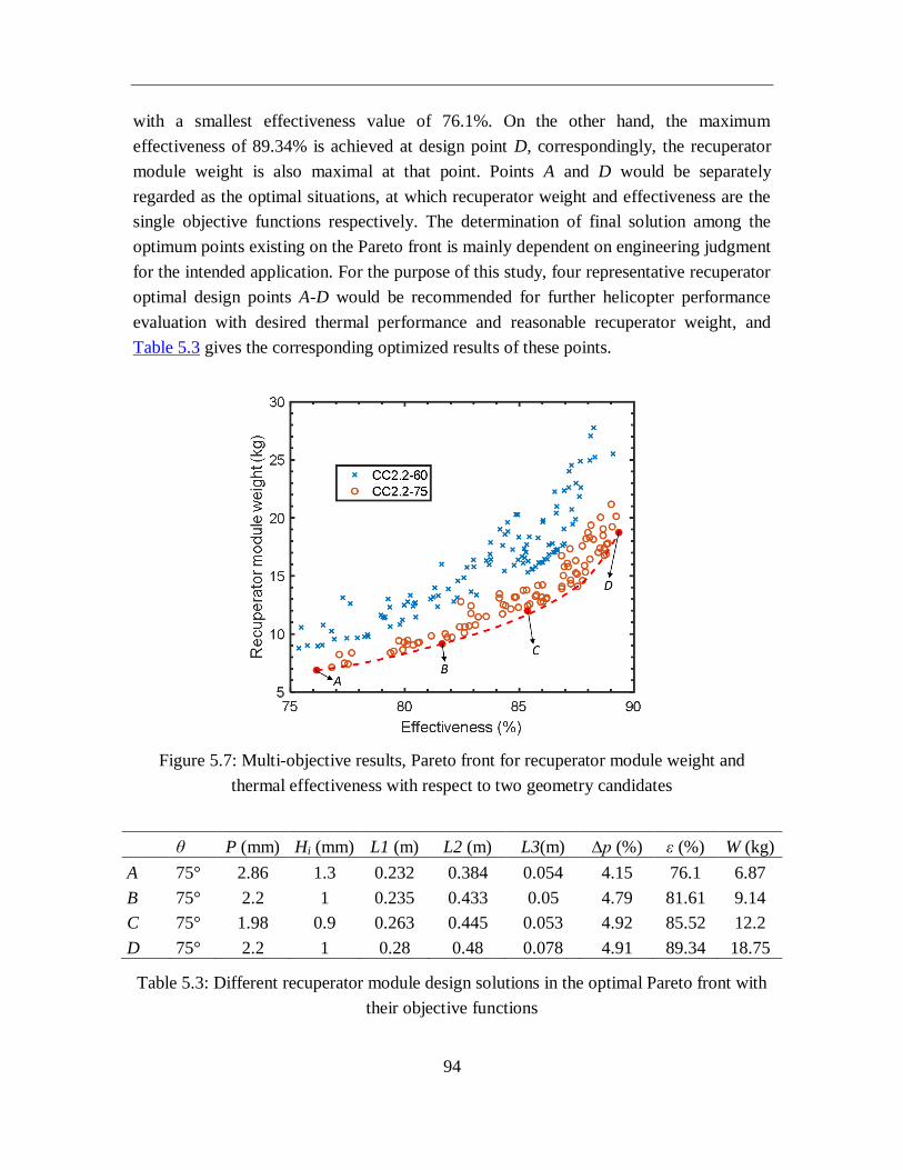
94
with a smallest effectiveness value of 76.1%. On the other hand, the maximum
effectiveness of 89.34% is achieved at design point D, correspondingly, the recuperator
module weight is also maximal at that point. Points A and D would be separately
regarded as the optimal situations, at which recuperator weight and effectiveness are the
single objective functions respectively. The determination of final solution among the
optimum points existing on the Pareto front is mainly dependent on engineering judgment
for the intended application. For the purpose of this study, four representative recuperator
optimal design points A-D would be recommended for further helicopter performance
evaluation with desired thermal performance and reasonable recuperator weight, and
Table 5.3 gives the corresponding optimized results of these points.
Figure 5.7: Multi-objective results, Pareto front for recuperator module weight and
thermal effectiveness with respect to two geometry candidates
θ P (mm) Hi (mm) L1 (m) L2 (m) L3(m) ∆p (%) ε (%) W (kg)
A 75° 2.86 1.3 0.232 0.384 0.054 4.15 76.1 6.87
B 75° 2.2 1 0.235 0.433 0.05 4.79 81.61 9.14
C 75° 1.98 0.9 0.263 0.445 0.053 4.92 85.52 12.2
D 75° 2.2 1 0.28 0.48 0.078 4.91 89.34 18.75
Table 5.3: Different recuperator module design solutions in the optimal Pareto front with
their objective functions

95
5.6 System evaluation
The helicopter plays an inimitable role in air transportation, and it is often used for
occasions including medical rescue, surveillance, law enforcement, fire suppression, etc.,
where environmental concerns would be considered secondary. The execution of this
study for system evaluation is therefore primarily devoted towards the fuel economy
improvement and associated system weight increment (namely parasitic recuperator
weight) arising from the incorporation of recuperator in optimized design solutions A-D,
so as to maximize rotorcraft range and payload capability in contrast to the conventional
non-recuperated helicopter. Comprehensive assessments are carried out in the rotorcraft
multidisciplinary simulation framework for three previously defined helicopter missions,
i.e. passenger air taxi (PAT), police surveillance (PSV) mission, and search & rescue
(SAR) mission, with the mission range varying from around 39 to 240 km, corresponding
to modern rotorcraft powerplant operations. To maintain simplification and consistency,
in the present work the helicopter only operates in the recuperated cycle under long time
hovering or cruise conditions.
The twin-engine, multi-purpose utility helicopter, based on the Bo105 configuration, has
been modified by incorporating two V-shaped recuperators in aforementioned optimal
designs. Simulated on representative mission scenarios, extensive comparisons are
carried out between helicopters employing the conventional simple cycle and advanced
recuperated turboshaft engines. While the integrated recuperator contributes to lower fuel
input requirement with higher thermal efficiency through the process of preheating
compressed air prior to the combustion chamber, the additional recuperator weight also
acts as a penalty for the limited carrying capability of the rotorcraft. In contrast to the
existing non-recuperated helicopter, the interdependency and associated trade-off
between saved fuel consumption offered by the adoption of recuperator and
corresponding weight penalty needs to be thoroughly quantified at mission level. Figure
5.8 depicts the calculation results for different recuperator design solutions A-D with
respect to the proposed helicopter missions.
Regarding the mission fuel consumption of the non-recuperated reference helicopter as
the baseline, as can be observed, a significant reduction in mission fuel burn is achieved
for all selected recuperator designs. Generally, the fuel consumption reduction is of the
order of around 33-40% for all proposed solutions, with regards to these three designated
missions.
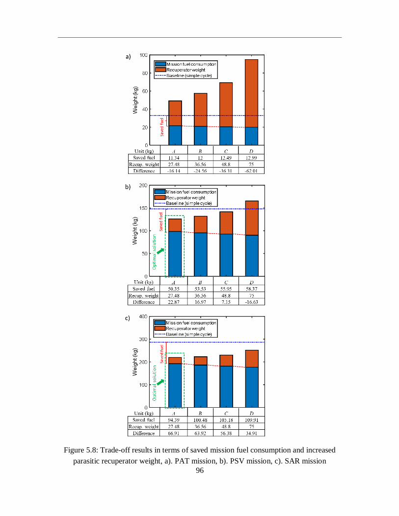
96
Figure 5.8: Trade-off results in terms of saved mission fuel consumption and increased
parasitic recuperator weight, a). PAT mission, b). PSV mission, c). SAR mission
97
To ensure a recuperated helicopter to be economically viable, the fuel saving should at
least be able to compensate for the additional recuperator weight. Obviously, results (the
sum of mission fuel burn and additional recuperator weight) exceed the indicated simple
cycle baseline would be regarded as an adverse operation for the implementation of
recuperator, such as all four solutions A-D for the PAT mission (see Figure 5.8a). The
weight difference between the increased weight and saved fuel are also listed in the table
below the figure, and positive values justify the need for recuperated cycle. It is noted
that the adoption of recuperator may not be suitable for certain type of helicopter
operations with short flight duration. The low range of 39 km for the assumed PAT
mission appears to be not sufficient to provide the required level of fuel reduction that
could offset the added recuperator weight in terms of all proposed recuperator design
solutions A-D. Representatively, the employed recuperator effectiveness is accepted as
the key design parameter that affects the improved fuel economy and associated weight
penalty in the recuperated cycle.
The PSV mission shows much positive and satisfying results for the potential of
recuperator utilization in contrast to PAT mission. Although the reduction in mission fuel
burn relative to non-recuperated simple cycle increases from solution A to D as a result of
the rising recuperator effectiveness, the dramatically increased recuperator weight penalty
gradually offsets the expected fuel saving benefits provided by the recuperation process.
The PSV mission would even turn into an unfavorable operation for recuperation
employment while recuperator design solution D is adopted, with a fuel burn reduction of
58.37 kg for the excessive recuperator weight of 75 kg (see Figure 5.8b). It is noted that
the fixed mission range and flight duration imposes a maximum achievable fuel saving
limitation while the helicopter conducts a specific task. Solution A proves to be optimal
case for the designated mission with the maximum weight difference between saved fuel
and added recuperator weight, and this obtained weight margin can either be utilized to
increase helicopter mission range or improve the useful payload depending on the actual
requirements and user preferences.
For recuperator optimized solutions A-D, the recuperator designed effectiveness varies
from 76.1% to 89.34%, while the total recuperator weight also increases significantly
from 27.48 kg to 75kg. With a substantial amount of fuel saving (94.39-109.91 kg) as
given in Figure 5.8c, the SAR mission appears to be a favorable and beneficial operation
for all considered recuperator design solutions. This mission profile could fulfill
sufficient fuel consumption reduction to compensate for the parasitic recuperator weight.
It is well concluded from the deployed mission analysis that the level of fuel reduction
during a specific helicopter mission is basically dependent on factors including the
98
mission profile, flight duration, recuperator effectiveness as well as type of operation.
Higher thermal effectiveness implies greater fuel saving potential with a more complete
utilization of exhaust waste heat, however it usually also necessitates larger recuperator
weight penalty. Due to the enormously increased tendency of required recuperator weight
over the thermal effectiveness, the optimal case is also obtained for solution A with
respect to the deployed SAR mission.
5.7 Summary
In this work, the multi-objective genetic algorithm optimization for recuperator design is
coupled with the integrated rotorcraft multidisciplinary simulation framework capable of
computing the helicopter flight dynamics and associated turboshaft engine performance
at mission levels, thus acting as a computationally efficient methodology to perform a
specific and comprehensive performance assessment of the rotorcraft powerplant
incorporating a potentially suitable, high performance recuperator. The main works and
findings could be summarized as follows:
1) The aero-thermal performance of various heat transfer surface geometries has been
considered and comparatively evaluated in terms of the volume and area goodness
factors Gvol and Garea, and promising candidates CC2.2-60 and CC2.2-75 are selected
for further geometry parameters and recuperator sizing optimization in recuperator
design.
2) The recuperator effectiveness maximization and corresponding weight minimization
are regarded as objective functions, and a set of multiple optimal solutions, namely
Pareto optimal solutions have been attained quantifying the interrelationship and
corresponding trade-off between these two conflicting goals. It is revealed that the
recuperator weight increases exponentially to achieve a high thermal effectiveness of
75% and above.
3) Four typical solutions were selected in optimal designs, and they have been further
evaluated under three representative mission scenarios targeting realistic helicopter
operations in an integrated multidisciplinary environment. It is concluded from the
substantial reduction in mission fuel consumption that the optimum level of
recuperator effectiveness is at around 75% for deployed mission scenarios within
flight range of up to 240 km, considering the parasitic recuperator weight.
99
6. Conclusions and outlooks
Air transportation is nowadays expanding remarkably with continuous growth in aviation
industry, and as an irreplaceable role, helicopters would find acceptance for both civil
and military applications in occasions like surveillance, fire suppression, search and
rescue etc. Turboshaft engines play a dominant part in helicopter propulsion, and they
provide attractive power-to-weight ratios in comparison with reciprocating engines.
Significant development efforts have been made to progressively improve engine
efficiency involving advanced manufacturing technologies, turbine blade cooling,
compressor and turbine aerothermal improvement etc. However, after several decades’
development, it is generally accepted to be increasingly difficult to achieve any further
promotion in thermal efficiency without major changes in engine architecture. Besides
that, from the start of the 21st century, environmental issues also pose a major challenge
for aeroengine design which attract great attention. The Advisory Council for Aerospace
Research and Innovation in Europe has set some ambitious goals on fuel saving and
emission reduction by 2020.
In order to meet the growing demand for highly efficient, environmentally friendly aero-
engines in the context of the increasingly stringent emissions legislation and serious
energy challenge, there is currently renewed interest in recuperated aeroengine
configurations for higher efficiency and lower emissions. Actually, the beneficial
recuperated cycle has long been recognized, it is well recognized that early development
activities and subsequent studies basically focused on utilizing tubular recuperators
exhibiting relatively low effectiveness of 60-70%, as they have high reliability based on
the then-current manufacturing technologies, together with the paramount design
requirement for light weight by the very nature of rotorcraft powerplant applications.
However, these recuperators have not been deployed due to early heat exchanger
impediments in terms of thermohydraulic performance, structural integrity, as well as
weight and volume consideration, along with the lack of market forces (i.e. simple-cycle
engine performance advancements, particularly in an era of low fuel cost).
100
6.1 Summary and conclusions
In this paper, to evaluate the operational performance of recuperated rotorcraft
powerplant, an integrated rotorcraft multidisciplinary simulation framework capable of
computing helicopter flight conditions and associated engine performance has been
proposed and developed adopting tubular or primary surface recuperator. The proposed
methodology is implemented to conduct a parametric investigation on recuperated
rotorcraft performance for any given flight condition as well as at mission level. The
performance of reference rotorcraft powerplant, modeled after the Bo 105 helicopter with
twin-engine configuration, has been initially assessed for a generic reference mission
scenario, and the overall approach and proposed methodology is then further extended for
four representative missions. The obtained results suggest that in spite of the substantial
reduction in mission fuel consumption, the deployment of recuperator may not be
favourable and beneficial for certain type of missions involving short duration and/or
small flight range, especially considering the prominent increase in recuperator weight
penalty.
In recent years, advancements in high temperature primary surface heat exchangers with
light weight, high effectiveness and improved reliability has started to emerge with the
development of advanced materials and improved manufacturing technologies,
highlighting its application to aeroengines without penalizing the operational capabilities
of existing rotorcraft powerplants.
In the next stage of our study, to understand the impact of recuperator on the whole
system for further development of future recuperated helicopter, it is proposed to assess
the potential of recuperated rotorcraft powerplant, with emphasis placed on highly
effective primary surface recuperator. The improved part-load performance against the
reference non-recuperated cycle is analyzed, and the beneficial fuel saving potential of
rotorcraft is evaluated under the flight condition of 0-250 km/h and 0-3000 m for
different recuperator design effectiveness values. It is suggested that the selection of
recuperator effectiveness should be dependent on the most commonly involved mission
profile and flight duration, in order to offset the added parasitic weight of the recuperator.
The integrated rotorcraft multidisciplinary framework proves to be an effective tool to
conduct a comprehensive assessment for the recuperated helicopter under different flight
conditions.
Besides that, we’ve further extended the established rotorcraft multidisciplinary
simulation framework through the employment of multi-objective GA optimization for
101
recuperator design, aimed at finding high performance primary surface heat exchangers
for applications to rotorcraft powerplants. A Pareto front model is obtained quantifying
the associated trade-off between the parasitic recuperator weight and thermal
effectiveness under defined constraints. Four optimal design solutions are selected, and
through the analysis of three representative helicopter missions, it is found that the
optimum trade-off between fuel saving benefits and associated recuperator weight
penalty is attained for the employed effectiveness of 76.1% with recuperator weight of
27.48 kg. The overall methodology essentially constitutes an enabling technology for the
multidisciplinary design and optimization of the rotorcraft powerplant system
incorporating a potentially suitable, high performance recuperator.
6.2 Outlooks
In continuation of the presented work, some further studies could focus on:
1) The investigation on environmental performance of recuperated rotorcraft. The
rotorcraft is typically used for occasions where environmental concerns would be
placed secondary (e.g. surveillance, law enforcement, military combat etc.). Hence,
this study mainly focuses on the fuel economy improvement and system weight
minimization to enhance rotorcraft range and payload capability. However, in today’s
climate of the increasingly stringent emissions legislation, the environmental impact
of civil aviation must be managed in the long-term considering the expanding air
transportation. With the adoption of recuperator, its influence on combustion process
and emissions would be of interest for analysis.
2) Specific design of recuperator with novel geometries. In our work, the design of
primary surface recuperator is performed with the selection of some cross-corrugated
heat transfer geometries. With the aid of computational fluid dynamics (CFD), heat
transfer coefficient and flow resistance of novel plate geometries could be calculated,
which could be potentially suitable for the intended use of our application with good
thermal performance, light weight and compact structure. Besides the investigation of
heat transfer performance of the recuperator matrix, some other important aspects
need taking great care in recuperator design, including longitudinal conduction
effects, flow maldistribution and fouling etc.
3) Experimental work and related testing. With regards to the Allison turboshaft engine,
extensive development work and measuring efforts have been undertaken at the Chair
of Turbomachinery and Flight Propulsion. If the recuperator could be fabricated and

102
materialized in terms of hardware, experimental analysis is required to prove its
structural integrity and reliability while operating in the severe thermally cyclic
environment. Besides that, particular attention also needs to be paid to the dynamic
performance of recuperator (especially at start up conditions), due to the thermal
inertia effect.
103
7. List of publications
7.1 Journal publications
1. Zhang, C. and Gümmer, V., ‘High temperature heat exchangers for recuperated rotorcraft
powerplants,’ Applied Thermal Engineering 2019; 154: 548-561.
2. Zhang, C. and Gümmer, V., ‘The Potential of helicopter turboshaft engines incorporating highly
effective recuperators under various flight conditions,’ Aerospace Science and Technology
2019;88:84-94.
3. Zhang, C. and Gümmer, V., ‘Performance assessment of recuperated rotorcraft powerplants:
Trade-off between fuel economy and weight penalty for both tubular and primary surface
recuperators,’ Applied Thermal Engineering, 2020;164:114443.
4. Zhang, C. and Gümmer, V., ‘Multi-objective optimization and system evaluation of recuperated
helicopter turboshaft engines,’ Energy, Paper number: EGY-D-19-04453. (accepted)
7.2 Peer-reviewed conference publications
1. Zhang,C., et al., ‘Evaluation of the fuel saving potential regarding recuperated helicopter flight
conditions,’ Proceedings of ASME Turbo Expo 2018, Oslo, Norway, GT2018-75637.
2. Zhang, C. and Gümmer, V., ‘Optimization design analysis of primary surface recuperator for
rotorcraft powerplant applications,’ Proceedings of ASME Turbo Expo 2019, GT2019-90842.
104
Bibliography
[1] McDonald, C.F. et al. ‘Recuperated gas turbine aeroengines, Part I: Early development activities,’
Aircraft Engineering and Aerospace Technology, 2008, 80(2):139-157.
[2] Wilson, D. G. and Korakianitis, T., The design of high-efficiency turbomachinery and gas turbines,
Prentice-Hall, Upper Saddle River, NJ, 1998.
[3] Walsh, P.P. and Fletcher, P., Gas turbine performance, Blackwell Science, 2nd
edition, 2004.
[4] McDonald, C.F. et al. ‘Recuperated gas turbine aeroengines. Part III: Engine concepts for reduced
emissions, lower fuel consumption, and noise abatement,’ Aircraft Engineering and Aerospace
Technology, 2008, 80(4):408-426.
[5] Bouty, E., Paty, G., Cheftel-PY, B. ‘SAGE 5 clean sky’s approach to quieter turboshaft engines,’
International Symposium on Air Breathing Engines, 2011, ISABE-2011-1303.
[6] MD 500E technical description. https://mdhelicopters.com/files/Models/MD500E_Tech_Desc.pdf
[7] Min, J.K. et al. ‘High temperature heat exchanger studies for applications to gas turbines,’ Heat
Mass Transfer, 2009, 46(2):175-86.
[8] Rotorcraft flying handbook, U.S. Department of Transportation, Federal Aviation Administration,
Chapter 5-2, 2000.
[9] Nkoi, B., Pilidis, P., et al., ‘Performance assessment of simple and modified cycle turboshaft gas
turbines,’ Propulsion and Power Research 2013;2(2):96-106.
[10] Fakhre, A., Pachidis, V., Goulos, I., Tashfeen, M., et al., ‘Helicopter mission analysis for a
regenerated turboshaft,’ in: Proceedings of ASME Turbo Expo 2013, San Antonio, Texas, 2013,
GT2013-94971.
[11] Traverso, A. and Massardo, A.F., ‘Optimal design of compact recuperators for microturbine
application,’ Applied Thermal Engineering, 2005, 25(14): 2054-2071.
[12] McDonald, C.F., Massardo, A.F. et al. ‘Recuperated gas turbine aeroengines, Part II: Engine
design studies following early development testing,’ Aircraft Engineering and Aerospace
Technology, 2008, 80(3):280-294.
105
[13] Sundén, B., ‘High temperature heat exchangers (HTHE),’ Proceedings of 5th international
conference on enhanced, compact and ultra-compact heat exchangers: science, engineering and
technology. Whistler, Canada, 2005.
[14] Jeong, J.H., Kim, L.S., et al., ‘Various heat exchangers utilized in gas-turbines for performance
enhancement,’ International Journal of Air-Conditioning and Refrigeration, 2008, 16(1):30-36.
[15] Dyste, N.L., ‘Economic and design aspects of gas turbine recuperators,’ Society of Automotive
Engineers (SAE) Paper 660019, 1966.
[16] USAAVLABS, ‘Heat regenerative system for T53 shaft turbine engines,’ Technical Report 65-37,
1965.
[17] Privoznik, E.J., ‘Allison T63 regenerative engine program,’ American Helicopter Society Meeting,
1968, Washington DC, paper 212.
[18] Privoznik, E.J. ‘T63 regenerative engine program: extended endurance and environmental testing,’
USAAVLABS Technical Report 68-88, 1968.
[19] Chapman, G.E., ‘The aircraft regenerative turbine engine: where now?,’ Society of Automotive
Engineers (SAE) Paper 8698, 1964.
[20] Stevens, J.H. ‘Regenerative turboprop for long-endurance aircraft,’ Flight International, 1964
November, pp. 834-6.
[21] Savostin, A.F. and Tikhonov, A.M., ‘Use of regeneration and elevated gas temperatures in
helicopter engines,’ Vertoletnyye Gasoturbinnyye Divigateli, Moscow, pp. 5-35, 1966.
[22] Young, P.H. ‘The heat-exchanger cycle: has its time come?,’ 1975, AIAA Paper 75-961.
[23] McDonald, C.F., ‘Study of lightweight integral regenerative gas turbine for high performance,’
USAAVLABS Technical Report 70-39, 1970 August.
[24] Andriani, R. et al., ‘Thermodynamic analysis of regeneration in propulsion,’ paper presented at
Workshop on Heat Engines, Florence, 1992 October.
[25] Bewley, A.D., ‘Cycle analysis for helicopter gas turbine engines,’ ASME Paper 89-GT-328, 1989.
[26] Tameo, R.W., Vinson, P.W., et al., ‘Regenerative engine analysis,’ USAAVRADCOM Report
TR-80-D-18, 1980.
[27] Schwaar, P. et al., ‘Regenerative engine analysis program,’ USAAVRADCOM Technical Report
TR-80-D-29, 1981.
[28] Heldenbrand, R.W. et al., ‘Regenerative engine analysis program,’ USAAVRADCOM Report
TR-81-D-2, 1981 January.
106
[29] Vinson, P.W. et al., ‘A study of regenerative turboshaft engines for light military helicopters,’
paper presented at ASME Gas Turbine Conference, Houston, 1981.
[30] Easterling, A.E. and Chesser, P., ‘Regenerative engine for helicopter application,’ paper
presented at American Helicopter Society Meeting, Washington, DC, 1980 May.
[31] Aviation Week & Space Technology, ‘Saturn/Lyulka diversifies business to cope with Russian
economic crisis,’ Aviation Week & Space Technology, 1992 March 30, pp. 44-6.
[32]Andriani, R. and Ghezzi, U., ‘Regeneration in propulsion,’ AIAA Paper 96-2792, 1996.
[33] Pletschacher, P., ‘Heat exchangers for turboshaft engines,’ lnteravia 42:503, 1987 May.
[34] Nina, M. and Aguas, M., ‘Heat exchangers in regenerative gas turbine cycles,’ AGARD
Proceedings, No. 390, 1985.
[35] Colantuoni, S. et al., ‘Preliminary design and performance of a variable geometry recuperative
turboshaft,’ AGARD Report CP-572, 1995.
[36] Pellischek, G. and Kumf, B. ‘Compact heat exchangers for aeroengines,’ International Society
for Air Breathing Engines (ISABE) Paper 91-7019, 1991.
[37] Miller, W.S. and Lee, S.J., ‘Recuperative heat exchangers for 500-hp helicopter engines,’ Paper
presented at ASIDE Gas Turbine Conference, Houston, Texas, 1981.
[38] Grieb, H. and Klussman, W., ‘Regenerative helicopter engines---advances in performance and
expected development problems,’ in AGARD Conference proc. No. 302, Helicopter Propulsion
Systems, 1981.
[39] Ponomarev, B.A., ‘Problems of applying regenerative heat exchangers in aviation engines,’ paper
presented at ICHMT Conference, Athens, 1992.
[40] Hirschkron, R. and Russo, C. J., ‘Small turboshaft/turboprop engine technology study,’ AIAA
Paper 86-1623, 1986.
[41] Cohen, E.E. and Jacoby, D., ‘An engine for tomorrow’s small helicopter,’ AIAA Paper 84-1277,
1984.
[42] Kaehler, H. and Schneider, W., ‘Small engine technology payoffs for future commuter aircraft,’
AIAA Paper 86-1544, 1986.
[43] Turk, M.A. and Zeiner, P.K., ‘Advanced technology payoff’s for future rotorcraft, commuter
aircraft, cruise missile and APU propulsion,’ AIAA Paper 86-1545, 1986.
[44] Piscopo, P.F. et al., ‘Fuel conservation benefits and critical technologies of recuperative and
advanced conventional cycle turboshaft engines,’ AIAA Paper 80-0224, 1980.
107
[45] Wilfert, G, et al., ‘CLEAN-validation of a high efficient low NOx core, a GTF high speed turbine
and an integration of a recuperator in an environmental friendly engine concept.’ 41st
AIAA/ASME/ASEE Joint propulsion conference, Tucson, Arizona, 2005 July 10-13, AIAA-
2005-4195.
[46] Krammer, P., Rued, K., Truebenbach, J., ‘Technology preparation for green aero engines,’ AIAA
Paper 2003-2790.
[47] Wilfert, G. et al., ‘New environmental friendly aero engine core concepts.’ ISABE-2007-1120,
Beijing, China, September.
[48] Schönenborn, H., Ebert, E., Simon, B., Storm, P., ‘Thermomechanical design of a heat exchanger
for a recuperative aero engine,’ Proceedings of ASME Turbo Expo 2004, Vienna, Austria, GT
2004-53696.
[49] Albanakis, C. et al. ‘The effect of heat transfer on the pressure drop through a heat exchanger for
aero engine applications.’ Applied Thermal Engineering, 2009, 29(4):634-644.
[50] Yakinthos, K. et al., ‘Optimization of the design of recuperative heat exchangers in the exhaust
nozzle of an aero engine.’ Applied Mathematical Modelling, 2007, 31:2524-2541.
[51] Missirlis, D., Donnerhack, S., Seite, O., Albanakis, C., et al., ‘Numerical development of a heat
transfer and pressure drop porosity model for a heat exchanger for aero engine applications,’
Applied Thermal Engineering 2010,30:1341-1350.
[52] Boggia, S. and Rüd, K., ‘Intercooled recuperated gas turbine engine concept,’ 41st AIAA
Aerospace Sciences Meeting including the New Horizons Forum and Aerospace Exposition,
AIAA 2005-4192.
[53] Recuperator for gas turbine engines, patent 2011, Pub. No.: US 2011/0146226 A1.
[54] Fakhre, A., et al., ‘A preliminary design trade-off study for an advanced propulsion technology
helicopter at mission level,’ ASME Journal of Engineering for Gas Turbines and Power, 2016,
138(1):012602.
[55] Zhang,C., et al., ‘Evaluation of the fuel saving potential regarding recuperated helicopter flight
conditions,’ Proceedings of ASME Turbo Expo 2018, Oslo, Norway, GT2018-75637.
[56] Fakhre, A., Pachidis, V., et al., ‘Helicopter mission analysis for a regenerative turboshaft engine,’
69th Annual Forum of the American Helicopter Society, Phoenix, Arizona, 2013.
[57] Lombardo, S., et al., ‘Evaluation and test of a liquid metal coupled regenerator system for aircraft
turboshaft engines,’ SAE Technical Paper 630492, 1963.
[58] Lombardo, S., ‘Component development of a liquid metal coupled regenerator system for
regenerator aircraft engines,’ SAE Technical Paper 640430, 1964.
108
[59] Ferris, J. R.,’ Liquid metal regenerator feasibility study for a light-weight turboshaft engine,’
TREC Technical Report 61-46, 1961.
[60] Moskowitz, S., et al., ‘Design and test evaluation of a liquid metal regenerator for gas turbines’
ASME 1972 International Gas Turbine and Fluids Engineering Conference and Products Show,
p. V001T01A032.
[61] McDonald, C.F. and Wilson, D. G., ‘The utilization of recuperated and regenerated engine cycles
for high-efficiency gas turbines in the 21st century,’ Applied Thermal Engineering, 1996, 16(8):
635-653.
[62] Cheeda, V. K., et al., ‘Design and CFD analysis of a regenerator for a turboshaft helicopter
engine,’ Aerospace Science and Technology, 2008, 12: 524-534.
[63] McDonald, C.F., ‘Heat-exchanged propulsion gas turbines: a candidate for future lower SFC and
reduced-emission military and civil aeroengines,’ Proceedings of ASME Turbo Expo 2009,
Florida, USA, GT2009-59156.
[64] Varga, B., ‘Power sources of military helicopters,’ Academic and Applied Research in Public
Management Science, 2018, 17(2): 139-168.
[65] Daly, M., Gunston, B., Jane’s aero-engines - Issue 28. IHS Jane’s Verlag, ISSN 1748-2534,
September 2010.
[66] Jackson, P., et al., Jane’s all the world’s aircraft 2003-2004 - Issue 94. Bath and Glasgow: Bath
Press Verlag, ISBN 0-7106-2537-5, 2003.
[67] Parker, K., Coombs, M., ‘Development in plate-fin heat exchangers.’ ASME Publication HTD, 10,
pp 171-179, 1979.
[68] Mishra, M., Das, P.K. and Sarangi, S., ‘Second law based optimization of crossflow plate-fin heat
exchanger design using genetic algorithm,’ Applied Thermal Engineering, 2009, 29:2983 -2989.
[69] Fernández-Seara, J., Diz, R., et al., ‘Pressure drop and heat transfer characteristics of a titanium
brazed plate-fin heat exchanger with offset strip fins,’ Applied Thermal Engineering, 2013, 51:
502-511.
[70] Takase, K., Furukawa, H., and Nakano, K., ‘A preliminary study of an intercooled and
recuperative microturbine below 300 kW,’ Proceedings of ASME Turbo Expo 2002, Amsterdam,
Netherlands, GT-2002-30403.
[71] Kays, W.M. and London, A.L. Compact heat exchangers. 3rd Edition, McGraw-Hill Book
Company, 1984.
[72] Shah, R.K., ‘Compact heat exchangers for microturbines,’ Neuilly-sur-Seine, France: RTO,
http://www.rto.nato.int/abstracts.asp; 2005.
109
[73] Ferrari, M.L., et al., ‘Recuperator dynamic performance: experimental investigation with a
microgas turbine test rig.’ Applied Energy, 2011, 88:5090-6.
[74] Tsai, B., Wang, Y.L., ‘A novel Swiss-Roll recuperator for the microturbine engine.’ Applied
Thermal Engineering, 2009, 29:216-23.
[75] Treece, B., Vessa, P., McKeirnan, R., ‘Microturbine recuperator manufacturing and operating
experience,’ Proceedings of ASME Turbo Expo 2002, Amsterdam, Netherlands, GT 2002-30404.
[76] Ferrari, M.L., Pascenti, M., McKeirnan, R., ‘Micro gas turbine recuperator: steady-state and
transient experimental investigation,’ ASME Journal of Engineering for Gas Turbines and Power
2010;132:022301-8.
[77] Zhang, L, Che, D. ‘Turbulence models for fluid flow and heat transfer between cross-corrugated
plates.’ Numerical Heat Transfer, Part A: Applications, 2011;60:410-40.
[78] Liu, F., Tsai, Y. ‘An experimental and numerical investigation of fluid flow in a cross-corrugated
channel.’ Heat Mass Transfer, 2010;46:585-93.
[79] Stasiek, J.A. ‘Experimental studies of heat transfer and fluid flow across corrugated-undulated
heat exchanger surfaces.’ International Journal of Heat and Mass Transfer, 1998;41:899-914.
[80] Du, L.X., et al., ‘Numerical investigations on thermohydraulic performance of cross-wavy
channels with multi-periodic boundary conditions.’ Numerical Heat Transfer, Part A:
Applications, 2014, 65:732-49.
[81] Wang, Q.W., et al. ‘Experimental investigation on heat transfer and pressure drop in a
microtubine recuperator with cross-wavy primary surface channels,’ Proceedings of ASME Turbo
Expo 2005, Nevada, USA, GT2005-68255.
[82] Xiao, G., Yang, T., Liu, H., Ni, D., et al. ‘Recuperators for micro gas turbines: A review,’
Applied Energy, 2017, 197: 83-99.
[83] Zhang, L. and Che, D., ‘Influence of corrugation profile on the thermal-hydraulic performance of
cross-corrugated plates,’ International Journal of Computation and Methodology 2011, 59: 267-
296.
[84] Utriainen, E. and Sundén, B. ‘A comparison of some heat transfer surfaces for small gas turbine
recuperators,’ Proceedings of ASME Turbo Expo 2001, New Orleans, Louisiana, USA, 2001-GT-
0474.
[85] Doo, J.H., Ha, M.Y., Min, J.K., Stieger, R., Rolt, R., Son, C., et al. ‘An investigation of cross-
corrugated heat exchanger primary surfaces for advanced intercooled-cycle aero engines (Part-I:
Novel geometry of primary surface),’ International Journal of Heat and Mass Transfer
2012;55:5256-67.
110
[86] Doo, J.H., Ha, M.Y., Min, J.K., et al. ‘An investigation of cross-corrugated heat exchanger
primary surfaces for advanced intercooled-cycle aero engines (Part-II: Design optimization of
primary surface).’ International Journal of Heat and Mass Transfer 2013; 61:138-48.
[87] Kim, M., et al. ‘Numerical study on the cross-corrugated primary surface heat exchanger having
asymmetric cross sectional profiles for advanced intercooled-cycle aero engines.’ International
Journal of Heat and Mass Transfer 2013;66:139-53.
[88] Lee, J. M., et al. ‘Characterizations of aerothermal performance of novel cross-corrugated plate
heat exchangers for advanced cycle aero-engines,’ International Journal of Heat and Mass
Transfer 2015, 85: 166-180.
[89] Kim, M., et al. ‘Experimental study on corrugated cross-flow air-cooled plate heat exchangers.’
Experimental Thermal and Fluid Science 2010;34:1265-72.
[90] Liu, X. D., Liu, H., Zhou, Li, ‘Numerical simulation of heat transfer in primary surface with
corrugations recuperators.’ World Academy of Science, Engineering and Technology
2010;41:621-6.
[91] McDonald, C.F., ‘Gas turbine recuperator technology advancements,’ ASME 1972 International
Gas Turbine and Fluids Engineering Conference and Products Show, 1972, 72-GT-32.
[92] Doty, F.D. et al. ‘The microtube strip heat exchanger,’ Heat Transfer Engineering, 1991, 12
(3):31-41.
[93] McDonald, C.F., ‘Recuperator considerations for future higher efficiency microturbines,’ Applied
Thermal Engineering 2003, 23(12): 1463-1487.
[94] Utriainen, E. and Sundén, B. ‘Recuperators in gas turbine systems.’ International Gas Turbine &
Aeroengine Congress & Exhibition 1998, Stockholm, Sweden, 98-GT-165.
[95] Ward, M.E., Stephenson, M.D. ‘Primary surface recuperator durability and applications,’ Report
No. TTS006/395. San Diego, CA: Solar Turbines, Inc.; 1995.
[96] Mehendale, S.S., Jacobi, A.M., Shah, R.K. ‘Fluid flow and heat transfer at micro- and meso-
scales with application to heat exchanger design.’ Applied Mechanics Reviews 2000, 53(7):175-
194.
[97] Utriainen, E. and Sundén, B. ‘Evaluation of the cross corrugation and some other candidate heat
transfer surface for microturbine recuperators,’ Journal of Engineering for Gas Turbines and
Power, 2002, 124(4): 550-560
[98] Doo, J.H., et al. ‘Theoretical prediction of longitudinal heat conduction effect in cross-corrugated
heat exchanger.’ International Journal of Heat and Mass Transfer 2012;55:4129-38.
111
[99] Pint, B.A., More, K.L., et al., ‘Comparison of recuperator alloy degradation in laboratory and
engine testing,’ Proceedings of ASME Turbo Expo 2006, Barcelona, Spain, GT2006-90194.
[100] Lara-Curzio, E., Trejo, R., et al. ‘Screening and evaluation of metallic materials for
microturbine recuperators,’ Proceedings of ASME Turbo Expo 2004, Vienna, Austria, GT2004-
54254.
[101] Harper, M.A., Smith, G.D., Maziasz, P.J., Swindeman, R.W., ‘Materials selection for high
temperature metal recuperators,’ Proceedings of ASME Turbo Expo 2001, New Orleans,
Louisiana, 2001-GT-0540.
[102] Pint, B.A. ‘Stainless steels with improved oxidation resistance for recuperators.’ ASME Journal
of Engineering for Gas Turbines and Power 2006;128:370-6.
[103] Maziasz, P.J. and Swindeman, R.W., ‘Selecting and developing advanced alloys for creep
resistance for microturbine recuperator applications,’ Proceedings of ASME Turbo Expo 2001,
New Orleans, Louisiana, 2001-GT-0541.
[104] Aquaro, D. and Pieve, M., ‘High temperature heat exchangers for power plants: Performance of
advanced metallic recuperators,’ Applied Thermal Engineering 2007,27: 389-400.
[105] Matthews, W.J., More, K.L., et al. ‘Long-term microturbine exposure of an advanced alloy for
microturbine primary surface recuperators,’ ASME Journal of Engineering for Gas Turbines and
Power 2009;131:32301.
[106] Matthews, W.J., More, K.L., Walker, L.R., ‘Comparison of three microturbine primary surface
recuperator alloys,’ ASME Journal of Engineering for Gas Turbines and Power 2010;132:22302.
[107] Wright, I.G. et al., ‘ODS alloy development,’ 17th Annual Fossil Energy Materials Conference,
Baltimore, MD, April 2003.
[108] Foerster, S., Kleemann, M., ‘Compact metallic and ceramic recuperators for gas turbines,’ 78-
GT-62, 1978.
[109] Carman, B.G., Kapat, J. S., Chow, L. C., An, L., ‘Impact of a ceramic microchannel heat
exchanger on a micro turbine,’ Proceedings of ASME Turbo Expo 2002, Amsterdam, Netherlands,
GT-2002- 30544.
[110] Nagarajan, V., Chen,Y., Wang,Q., Ting,M., ‘Hydraulic and thermal performances of a novel
configuration of high temperature ceramic plate-fin heat exchanger.’ Applied Energy,
2014;113:589-602.
[111] Kleiner, R.N., Strasbaugh, L. R., Coubrough, L. E., ‘Highly compact ceramic recuperator for
engine applications,’ 84-GT-50, 1984.
112
[112] Wilson, M. A., et al., ‘Design and development of a low-cost, high temperature silicon carbide
micro-channel recuperator,’ Proceedings of ASME Turbo Expo 2005, Nevada, USA, GT2005-
69143.
[113] McDonald, C.F. and Rodgers, C., ‘Small recuperated ceramic microturbine demonstrator
concept.’ Applied Thermal Engineering 2008;28:60-74.
[114] Vick, M. J., Heyes, A., Pullen, K., ‘Design overview of a three kilowatt recuperated ceramic
turboshaft engine,’ ASME Journal of Engineering for Gas Turbines and Power 2009, 132(9):
092301-9.
[115] Vick, M., ‘High efficiency recuperated ceramic gas turbine engines for small unmanned air
vehicle propulsion,’ Imperial College London, PhD thesis 2012.
[116] Kelly, M. M., Pan, M., Atre, S, et al., ‘Ceramic microchannel recuperator fabrication methods
for small gas turbine engines,’ Proceedings of ASME Turbo Expo 2012, Copenhagen, Denmark,
GT2012-68510
[117] Halbig, M, et al., ‘Evaluation of ceramic matrix composite technology for aircraft turbine engine
applications,’ 51st AIAA Aerospace Sciences Meeting including the New Horizons Forum and
Aerospace Exposition, AIAA 2013-0539
[118] Kiser, J.D., et al., ‘Overview of CMC (Ceramic Matrix Composite) research at the NASA glenn
research center.’ NASA Glenn Research Center; 2016.
[119] Suder, K., ‘Overview of the NASA environmentally responsible aviation project’s propulsion
technology portfolio,’ 48th AIAA/ASME/SAE/ASEE Joint Propulsion Conference & Exhibit,
Atlanta, Georgia, AIAA 2012-4038.
[120] Kerler, M., ‘Methods for numerical calculation of the helicopter power demand,’ Technical
Report (LFA 2011-20), Institute for Flight Propulsion, Technical University of Munich.
[121] Kerler, M., Heibel, Y., Erhard, W., ‘Evaluation of future helicopter powertrain concepts
regarding flight mission and operational aspects,’ American Helicopter Society 72nd Annual
Forum Proceedings, West Palm Beach, FA, USA, May 17th-19th 2016.
[122] Müller, H., ‘Modelling of the turboshaft engine Allison 250-C20B,’ Technical Report (LFA
2012-067), Institute for Flight Propulsion, Technical University of Munich.
[123] Kerler, M., et al. ‘Helicopter engine-in-the-loop test setup,’ 39th European Rotorcraft Forum,
Moscow, Russia, September 3rd-6th, 2013.
[124] Zhang, C. and Gümmer, V., ‘High temperature heat exchangers for recuperated rotorcraft
powerplants,’ Applied thermal engineering 2019; 154: 548-561.
113
[125] Leishman, J.G. Principles of helicopter aerodynamics, 2nd Edition, Cambridge University Press,
New York.
[126] Seddon, J., Newman, S. Basic helicopter aerodynamics, 3rd Edition, John Wiley & Sons,
Chichester, UK.
[127] Kerler, M, Erhard, W., ‘Evaluation of helicopter flight missions with intended single engine
operation,’ 40th European Rotorcraft Forum, Southampton, UK.
[128] Kurzke, J., GasTurb 12 User’s Manual, 2012, Munich.
[129] Sommers, A., Wang, Q., Han, X., et al., ‘Ceramics and ceramic matrix composites for heat
exchangers in advanced thermal systems-A review,’ Applied Thermal Engineering, 2010, 30:
1277-1291.
[130] Xie, G. N., Sundén, B., Wang, Q.W., ‘Optimization of compact heat exchangers by a genetic
algorithm,’ Applied Thermal Engineering, 2008, 28(89): 895-906.
[131] McDonald, C.F., ‘Low-cost compact primary surface recuperator concept for microturbines,’
Applied Thermal Engineering, 2000, 20(5): 471-497.
[132] McDonald, C.F., ‘Low cost recuperator concept for microturbine applications,’ Proceedings of
ASME Turbo Expo, Munich, Germany, 2000-GT-167.
[133] Focke, W.W., Zachariades, J., et al., ‘The effect of the corrugation inclination angle on the
thermohydraulic performance of plate heat exchangers,’ International Journal of Heat and Mass
Transfer, 1985, 28: 1469-1479.
[134] Blomerius, H. and Mitra, N.K., ‘Numerical investigation of convective heat transfer and
pressure drop in wavy ducts,’ Numerical Heat Transfer, Part A 2000,37 (1): 37-54.
[135] Stasiek, J., Collins, M. W., Ciofalo, M, et al., ‘Investigation of flow and heat transfer in
corrugated passages-I. Experimental results,’ International Journal of Heat and Mass Transfer,
1996, 39(1): 149-164.
[136] Ciofalo, M., Stasiek, J., Collins, M. W., ‘Investigation of flow and heat transfer in corrugated
passages-II.’ Numerical simulations, International Journal of Heat and Mass Transfer, 1996,
39(1): 165-192.
[137] Yin, J. X., Li, G. G., and Feng, Z. P., ‘The effects of the corrugation angle on flow and heat
transfer in cross corrugation channels with sinusoidal wave,’ Proceedings of ASME Turbo Expo,
Nevada, USA, GT2005-68282.
[138] Elshafei, E.A.M., Awad, M.M., El-Negiry, E. and Ali, A.G., ‘Heat transfer and pressure drop in
corrugated channels,’ Energy, 2010,35:101-110.
114
[139] Zhang, L.Z., ‘Turbulent three-dimensional air flow and heat transfer in a cross-corrugated
triangular duct,’ ASME Journal of Heat Transfer, 2005, 127:1151
[140] Sparrow, E.M., Comb, J.W., ‘Effect of interwall spacing and fluid flow inlet conditions on a
corrugated-wall heat exchanger,’ International Journal of Heat and Mass Transfer,
1983;26(7):993-1005.
[141] Islamoglu, Y. and Parmaksizoglu, C., ‘The effect of channel height on the enhanced heat
transfer characteristics in a corrugated heat exchanger channel,’ Applied Thermal Engineering,
2003; 23:979-87.
[142] Sang, I., Hyung, N., ‘Experimental study on flow and local heat/mass transfer characteristics
inside corrugated duct,’ International Journal of Heat and Fluid Flow, 2006;27:21-32.
[143] Ali, M., Ramadhyani, S., ‘Experiments on convective heat transfer in corrugated channels,’
Experimental Heat Transfer, 1992;5:175-93.
[144] Nishimura, T., Yano, K., Yoshino, T., Kawamura, Y., ‘Occurrence and structure of Taylor–
Goertler vortices induced in two-dimensional wavy channels for steady flow,’ Journal of
Chemical Engineering of Japan,1990;23(6):697-703.
[145] Muley, A., Sundén, B., ‘Advances in recuperator technology for gas turbine system,’ ASME
International Mechanical Engineering Congress, Washington, USA, Paper No. IMECE 2003-
43294.
[146] Wang, L., Deng, L., Ji, C., et al., ‘Multi-objective optimization of geometrical parameters of
corrugated-undulated heat transfer surfaces,’ Applied Energy, 2016, 174: 25-36.
[147] Liu, Z., Cheng, H., ‘Multi-objective optimization design analysis of primary surface recuperator
for microturbines,’ Applied Thermal Engineering, 2008,28: 601-610.
[148] Liang, C., Tong, X., Lei, T. and Li, Z., ‘Optimal design of an air-to-air heat exchanger with
cross-corrugated triangular ducts by using a particle swarm optimization algorithm,’ Applied
Science 2017,7: 554.
[149] Micheli, D., Pediroda, V., Pieri, S., ‘Multi-objective optimization of a microturbine compact
recuperator,’ ASME Journal of Engineering for Gas Turbines and Power 2008, 130:032301.
[150] Sanaye, S. and Hajabdollahi, H., ‘Thermal-economic multi-objective optimization of plate fin
heat exchanger using genetic algorithm,’ Applied Energy, 2010, 87:1893-1902.
[151] Shah, R.K., London, A.L., Laminar flow forced convection in ducts, Academic Press, Inc, New
York, 1978.

115
[152] Liang, H. X., Wang, Q., Luo, L., Feng, Z., ‘Numerical simulation of gas flow and heat transfer
in cross-wavy primary surface channel for microtubine recuperators.’ Proceedings of ASME
Turbo Expo, Nevada, USA, 2005-GT-68292.
[153] Deb, K., Pratap, A., Agarwal, S., Meyarivan, T., ‘A fast and elitist multiobjective genetic
algorithm: NSGA-II.’ IEEE Transactions on Evolutionary Computation, 2002, 6:182-97.
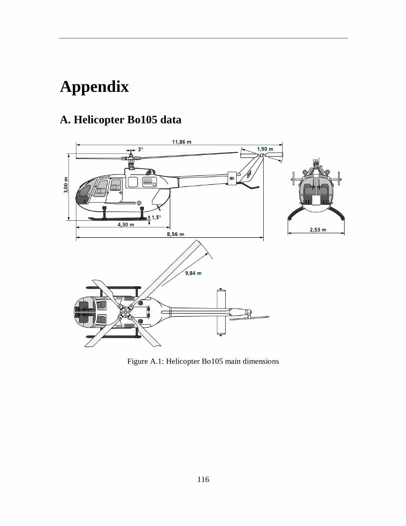
116
Appendix
A. Helicopter Bo105 data
Figure A.1: Helicopter Bo105 main dimensions
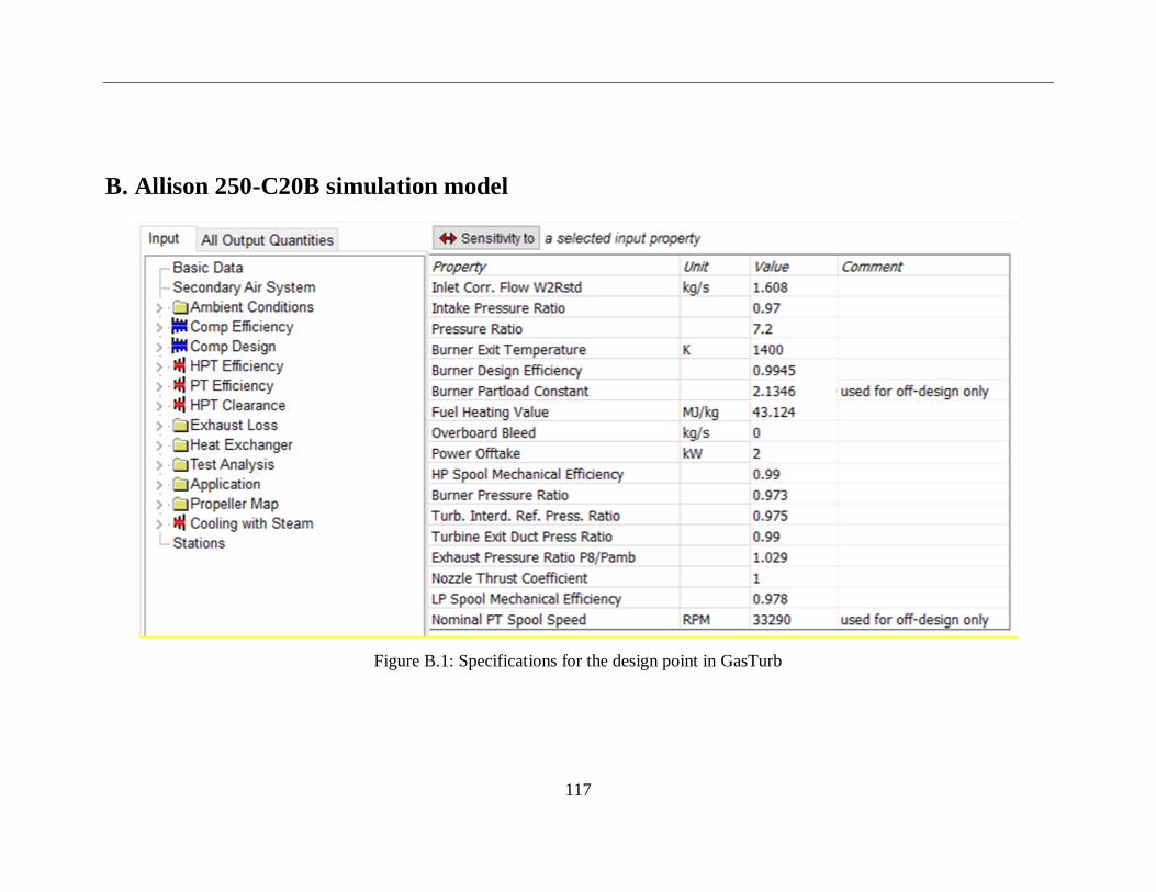
117
B. Allison 250-C20B simulation model
Figure B.1: Specifications for the design point in GasTurb
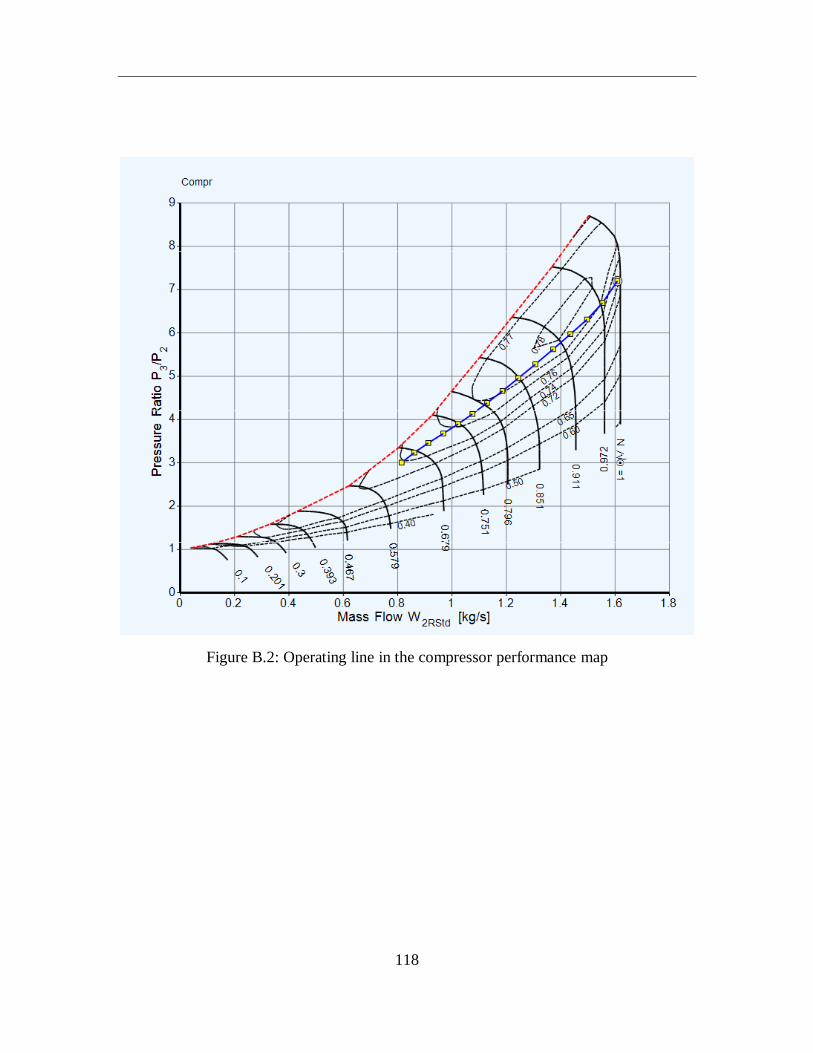
118
Figure B.2: Operating line in the compressor performance map
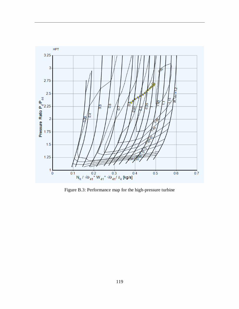
119
Figure B.3: Performance map for the high-pressure turbine
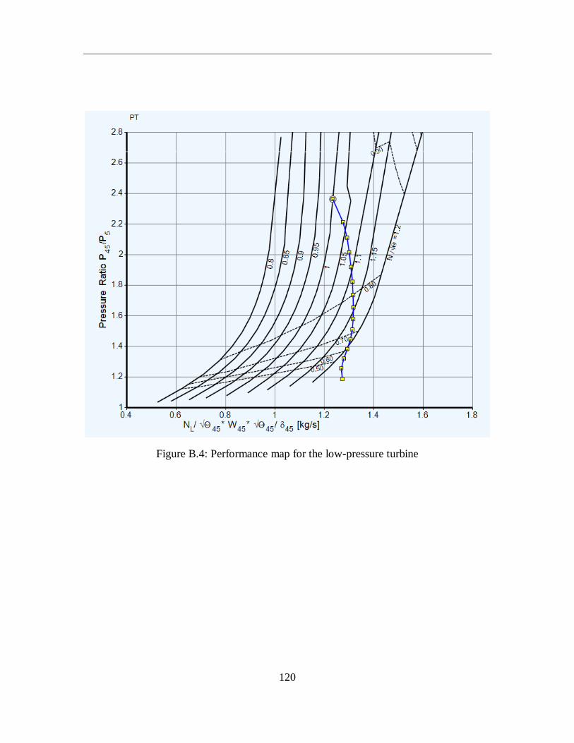
120
Figure B.4: Performance map for the low-pressure turbine


![Medizinische Hochschule Hannover Zentrum Innere Medizin ......1.1.1 Epidemiology and natural history Hepatitis C virus was discovered in 1989 by M.Houghton and colleague [1]. Worldwide,](https://img.pdfslide.org/doc/110x75/61473933afbe1968d379eb40/medizinische-hochschule-hannover-zentrum-innere-medizin-111-epidemiology.jpg)
![Franz SCHUBERT 1 Die Götter Griechenlands, D. 677 [4:26] A 2 B … · 2018. 12. 18. · Athens, the city where her great colleague had grown up, and dedicated it to Callas’ memory](https://img.pdfslide.org/doc/110x75/5fe34ae92f6031161a314848/franz-schubert-1-die-gtter-griechenlands-d-677-426-a-2-b-2018-12-18.jpg)