Embed Size (px)
Citation preview
FLUXA-Control Product Information (January 2007)
DIN EN ISO 9001:2000
C:\Data KARL DEUTSCH\KD PRODUKTE Laptop\FLUXA-Control\FLUXA-Control Paper SV-WD Jan07.doc 16.Jan-2007
KARL DEUTSCH Prüf-und Messgerätebau GmbH+ Co KG � Otto-Hausmann-Ring 101�D-42115 Wuppertal �Tel. (+49 -202)71 92 -0 �Fax (+49 -202) 71 49 32� e-mail: [email protected] 1 von 6
FLUXA-CONTROL: AN AUTOMATED MONITORING OF FLUORESCENTPARTICLES IN MAGNETIC PARTICLE TESTING
V. Schuster, V. Deutsch, W. A. K. Deutsch, F. Bartholomai, P. Müller
KARL DEUTSCH NDT-Instruments, Sensors & Systems, Wuppertal Germany
[email protected], www.karldeutsch.de
1 IntroductionMagnetic particle testing (MT) is the most sensitive method to detect surface cracks in ferromagnetic materials [2].This method can be executed by mobile equipment or stationary systems [3]. Magnetic particles are used for thevisualisation of the surface cracks. The magnetic particles are an iron oxide powder coated with visible orfluorescent paint. They are also called test agent or magnetic ink. For mobile test tasks, the magnetic particles arenormally applied as a wet suspension from aerosol cans. The magnetic particles are only used once. Therefore thelongterm stability is not an issue. On the other hand, for stationary systems the magnetic particle is contained in aclosed circuit and is used for many hours. A suspension of magnetic particles diluted in water (or sometimes oil) iskept in constant circulation. The properties of the magnetic particles degrade over time and have to be controlled inregular intervals.
Due to the higher contrast, fluorescent magnetic particles are used for most test applications, so that fluorescentparticle control is more urgently required than control of visible particles. A surface defect should show highcontrast under ultraviolet light. The indication should be sharp with virtually no background either from the particlesthemselves or from the flawless surface of the testpiece. It is very difficult to detect the fluorescent crack indicationswith high fluorescent backgrounds.
Moreover is it important to have a good sensitivity of fluorescent particles for crack detection. Three reasons arisefor the degrading of fluorescent magnetic particles:
1. More and more particles are dragged out of the circuit by sticking on every tested workpiece.
2. An increased pollution by dirt, scale, oil or other media appears during using.
3. Separation between fluorescent colour and the iron oxide occurs.
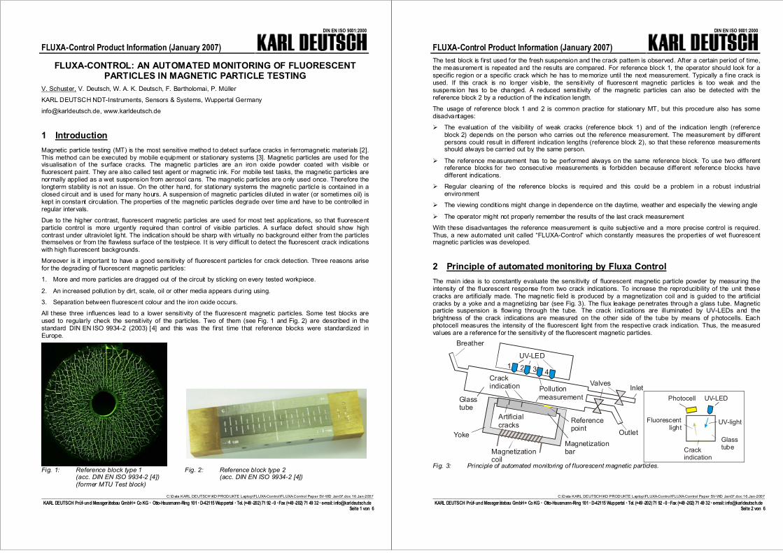
All these three influences lead to a lower sensitivity of the fluorescent magnetic particles. Some test blocks areused to regularly check the sensit ivity of the particles. Two of them (see Fig. 1 and Fig. 2) are described in thestandard DIN EN ISO 9934-2 (2003) [4] and this was the first time that reference blocks were standardized inEurope.
Fig. 1: Reference block type 1(acc. DIN EN ISO 9934-2 [4])(former MTU Test block)
Fig. 2: Reference block type 2(acc. DIN EN ISO 9934-2 [4])
FLUXA-Control Product Information (January 2007)
DIN EN ISO 9001:2000
C:\Data KARL DEUTSCH\KD PRODUKTE Laptop\FLUXA-Control\FLUXA-Control Paper SV-WD Jan07.doc 16.Jan-2007
KARL DEUTSCH Prüf-und Messgerätebau GmbH+ Co KG � Otto-Hausmann-Ring 101�D-42115 Wuppertal �Tel. (+49 -202)71 92 -0 �Fax (+49 -202) 71 49 32� e-mail: [email protected] 2 von 6
The test block is first used for the fresh suspension and the crack pattern is observed. After a certain period of time,the measurement is repeated and the results are compared. For reference block 1, the operator should look for aspecific region or a specific crack which he has to memorize until the next measurement. Typically a fine crack isused. If this crack is no longer visible, the sensit ivity of fluorescent magnetic particles is too weak and thesuspension has to be changed. A reduced sensit ivity of the magnetic particles can also be detected with thereference block 2 by a reduction of the indication length.
The usage of reference block 1 and 2 is common practice for stationary MT, but this procedure also has somedisadvantages:
� The evaluation of the visibility of weak cracks (reference block 1) and of the indication length (referenceblock 2) depends on the person who carries out the reference measurement. The measurement by differentpersons could result in different indication lengths (reference block 2), so that these reference measurementsshould always be carried out by the same person.
� The reference measurement has to be performed always on the same reference block. To use two differentreference blocks for two consecutive measurements is forbidden because different reference blocks havedifferent indications.
� Regular cleaning of the reference blocks is required and this could be a problem in a robust industrialenvironment
� The viewing condit ions might change in dependence on the daytime, weather and especially the viewing angle
� The operator might not properly remember the results of the last crack measurement
With these disadvantages the reference measurement is quite subjective and a more precise control is required.Thus, a new automated unit called “FLUXA-Control” which constantly measures the properties of wet fluorescentmagnetic particles was developed.
2 Principle of automated monitoring by Fluxa ControlThe main idea is to constantly evaluate the sensitivity of fluorescent magnetic particle powder by measur ing theintensity of the fluorescent response from two crack indications. To increase the reproducibility of the unit thesecracks are artificially made. The magnetic field is produced by a magnetization coil and is guided to the artificialcracks by a yoke and a magnetizing bar (see Fig. 3). The flux leakage penetrates through a glass tube. Magneticparticle suspension is flowing through the tube. The crack indications are illuminated by UV-LEDs and thebrightness of the crack indications are measured on the other side of the tube by means of photocells. Eachphotocell measures the intensity of the fluorescent light from the respective crack indication. Thus, the measuredvalues are a reference for the sensitivity of the fluorescent magnetic particles.
UV-LED
Artificialcracks Reference
point
Pollutionmeasurement
Breather
Inlet
Outlet
Valves
Glasstube
Magnetizationcoil
Crackindication
1 2 3 4
Magnetizationbar
Yoke
UV-LEDPhotocell
UV-lightFluorescentlight
Crackindication
Glasstube
Fig. 3: Principle of automated monitoring of f luorescent magnetic particles.
FLUXA-Control Product Information (January 2007)
DIN EN ISO 9001:2000
C:\Data KARL DEUTSCH\KD PRODUKTE Laptop\FLUXA-Control\FLUXA-Control Paper SV-WD Jan07.doc 16.Jan-2007
KARL DEUTSCH Prüf-und Messgerätebau GmbH+ Co KG � Otto-Hausmann-Ring 101�D-42115 Wuppertal �Tel. (+49 -202)71 92 -0 �Fax (+49 -202) 71 49 32� e-mail: [email protected] 3 von 6
The glass tube is made from special material and fulfils the following tasks:
� Transparent for UV-light and visible (fluorescent) light.
� Minimum pollution of the smooth inner surface with magnetic particles. After every measurement cycle thecomplete magnetic particles are washed out to keep the glass tube as clean as possible, so that the sensitivitymeasurement can carry out during many cycles.
The measurement process is controlled by an electric circuit. One cycle consists of the following steps:
� Filling of the glass tube with magnetic suspension via the inlet,
� magnetization by the magnetization coil,
� flow out during magnetization via outlet,
� evaluation of the intensity of crack indications,
� demagnetization of the yoke containing the artificial cracks,
� filling of the glass tube via inlet,
� flow out without magnetization via outlet and wipe off the former crack indications.
3 Control mechanismThe sensitivity evaluation of the fluorescent particles is based on the crack measurements with the UV-LEDs no. 1and 2. In addition, the automated monitoring system includes two different control mechanisms:
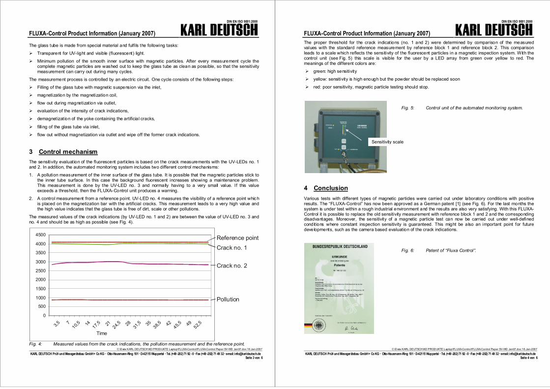
1. A pollution measurement of the inner surface of the glass tube. It is possible that the magnetic particles stick tothe inner tube surface. In this case the background fluorescent increases showing a maintenance problem.This measurement is done by the UV-LED no. 3 and normally having to a very small value. If this valueexceeds a threshold, then the FLUXA-Control unit produces a warning.
2. A control measurement from a reference point. UV-LED no. 4 measures the visibility of a reference point whic his placed on the magnetization bar with the artificial cracks. This measurement leads to a very high value andthe high value indicates that the glass tube is free of dirt, scale or other pollutions.
The measured values of the crack indications (by UV-LED no. 1 and 2) are between the value of UV-LED no. 3 andno. 4 and should be as high as possible (see Fig. 4).
0
500
1000
1500
2000
2500
3000
3500
4000
4500
3,5 710,5 14 17,5 21 24,5 2831
,5 3538,5 4245,5 4952,5
Time
Reference pointCrack no. 1
Crack no. 2
Pollution
Fig. 4: Measured values from the crack indications, the pollution measurement and the reference point.
FLUXA-Control Product Information (January 2007)
DIN EN ISO 9001:2000
C:\Data KARL DEUTSCH\KD PRODUKTE Laptop\FLUXA-Control\FLUXA-Control Paper SV-WD Jan07.doc 16.Jan-2007
KARL DEUTSCH Prüf-und Messgerätebau GmbH+ Co KG � Otto-Hausmann-Ring 101�D-42115 Wuppertal �Tel. (+49 -202)71 92 -0 �Fax (+49 -202) 71 49 32� e-mail: [email protected] 4 von 6
The proper threshold for the crack indications (no. 1 and 2) were determined by comparison of the measuredvalues with the standard reference measurement by reference block 1 and reference block 2. This comparisonleads to a scale which reflects the sensitivity of the fluorescent particles in a magnetic inspection system. With thecontrol unit (see Fig. 5) this scale is visible for the user by a LED array from green over yellow to red. Themeanings of the different colors are:
� green: high sensitivity
� yellow: sensitivity is high enough but the powder should be replaced soon
� red: poor sensitivity, magnetic particle testing should stop.
Fig. 5: Control unit of the automated monitoring system.
4 ConclusionVarious tests with different types of magnetic particles were carried out under laboratory conditions with positiveresults. The “FLUXA-Control” has now been approved as a German patent [1] (see Fig. 6). For the last months thesystem is under test within a rough industrial environment and the results are also very satisfying. With this FLUXA-Control it is possible to replace the old sensitivity measurement with reference block 1 and 2 and the correspondingdisadvantages. Moreover, the sensitivity of a magnetic particle test can now be carried out under well-definedcondit ions where constant inspection sensitivity is guaranteed. This might be also an important point for futuredevelopments, such as the camera based evaluation of the crack indications.
Fig. 6: Patent of “Fluxa Control”.
Sensitivity scale
FLUXA-Control Product Information (January 2007)
DIN EN ISO 9001:2000
C:\Data KARL DEUTSCH\KD PRODUKTE Laptop\FLUXA-Control\FLUXA-Control Paper SV-WD Jan07.doc 16.Jan-2007
KARL DEUTSCH Prüf-und Messgerätebau GmbH+ Co KG � Otto-Hausmann-Ring 101�D-42115 Wuppertal �Tel. (+49 -202)71 92 -0 �Fax (+49 -202) 71 49 32� e-mail: [email protected] 5 von 6
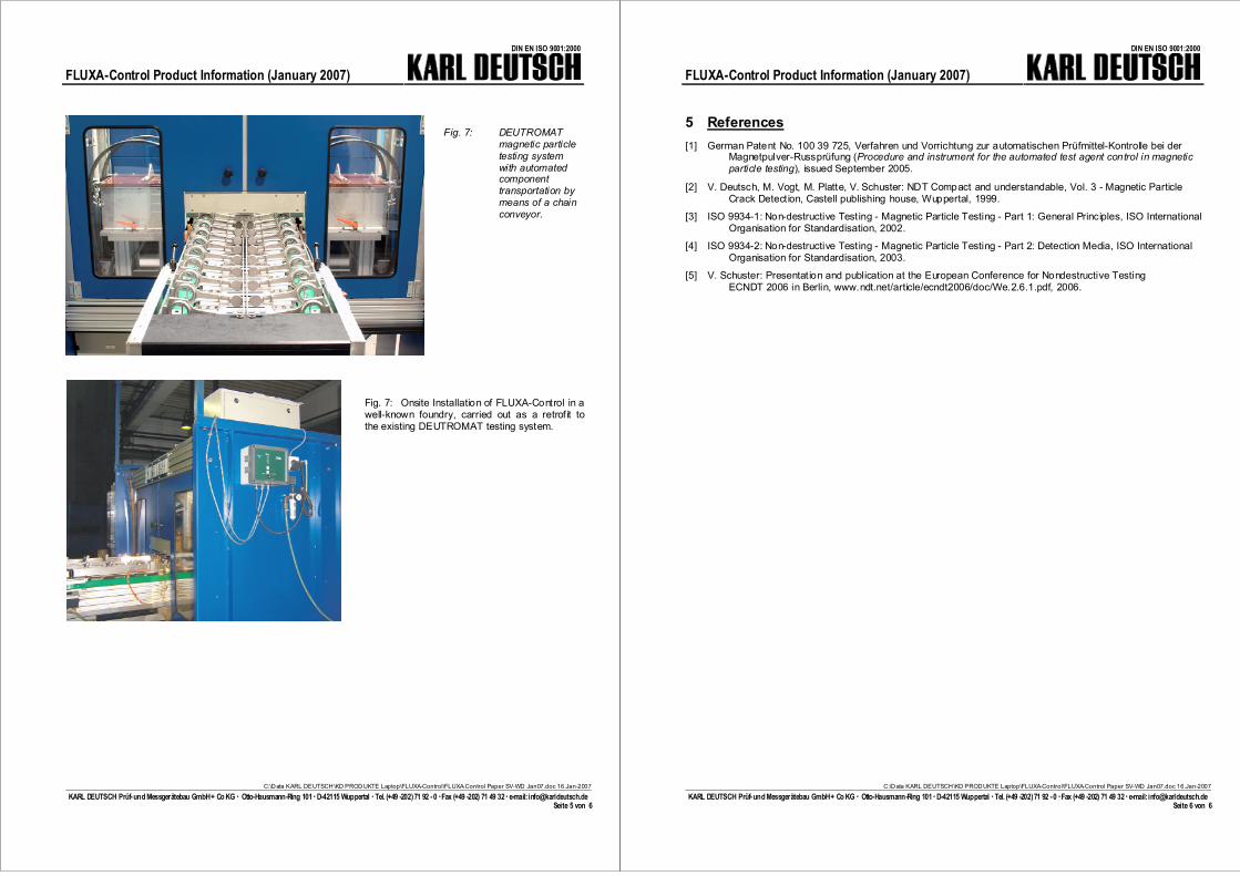
Fig. 7: DEUTROMATmagnetic particletesting systemwith automatedcomponenttransportation bymeans of a chainconveyor.
Fig. 7: Onsite Installation of FLUXA-Control in awell-known foundry, carried out as a retrofit tothe existing DEUTROMAT testing system.
FLUXA-Control Product Information (January 2007)
DIN EN ISO 9001:2000
C:\Data KARL DEUTSCH\KD PRODUKTE Laptop\FLUXA-Control\FLUXA-Control Paper SV-WD Jan07.doc 16.Jan-2007
KARL DEUTSCH Prüf-und Messgerätebau GmbH+ Co KG � Otto-Hausmann-Ring 101�D-42115 Wuppertal �Tel. (+49 -202)71 92 -0 �Fax (+49 -202) 71 49 32� e-mail: [email protected] 6 von 6
5 References[1] German Patent No. 100 39 725, Verfahren und Vorrichtung zur automatischen Prüfmittel-Kontrolle bei der
Magnetpulver-Russprüfung (Procedure and instrument for the automated test agent control in magneticparticle testing), issued September 2005.
[2] V. Deutsch, M. Vogt, M. Platte, V. Schuster: NDT Compact and understandable, Vol. 3 - Magnetic ParticleCrack Detection, Castell publishing house, Wuppertal, 1999.
[3] ISO 9934-1: Non-destructive Testing - Magnetic Particle Testing - Part 1: General Principles, ISO InternationalOrganisation for Standardisation, 2002.
[4] ISO 9934-2: Non-destructive Testing - Magnetic Particle Testing - Part 2: Detection Media, ISO InternationalOrganisation for Standardisation, 2003.
[5] V. Schuster: Presentation and publication at the European Conference for Nondestructive TestingECNDT 2006 in Berlin, www.ndt.net/article/ecndt2006/doc/We.2.6.1.pdf, 2006.

![Quasaar · IT- T ech n ik [ In stillo] ... QC & product control Stability studies Analytics & methods Technology transfer GMP-support GMP-consulting Product optimization nanoSaar](https://img.pdfslide.org/doc/110x75/5d52309088c993a81d8baa92/-it-t-ech-n-ik-in-stillo-qc-product-control-stability-studies-analytics.jpg)