Embed Size (px)
Citation preview
M1.2.HB435-HB450.NLFREN - 14052018
HANDLEIDING - MODE D’EMPLOI - MANUAL
HB435 (724563062) HB450 (724563066)
Hefbrug 4 kolommenPont élévateur à 4 colonnes
4-Post hydraulic lift
P.02 Gelieve te lezen en voor later gebruik bewarenP.20 Veuillez lire et conserver pour consultation ultérieureP.38 Please read and keep for future reference
FR
EN
NL
copy
righte
d do
cume
nt - a
ll rig
hts re
serv
ed b
y FB
C
M1.2.HB435-HB450.NLFREN - 14052018
2
NL
1 Verpakking, transport en opslag
AANDACHT!Het verpakken, heffen, behandelen, vertransporteren en uitpakken mag enkel door bekwaam personeel worden uitgevoerd.
1.1 Verpakking
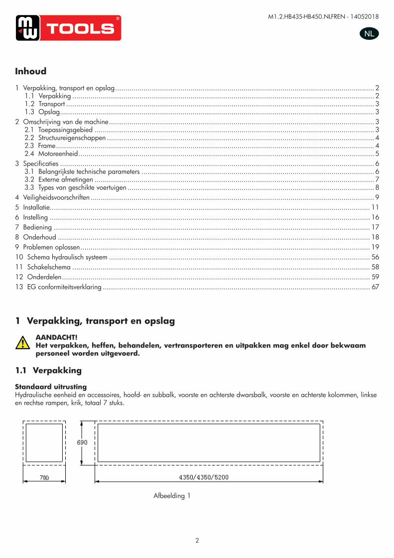
Standaard uitrustingHydraulische eenheid en accessoires, hoofd- en subbalk, voorste en achterste dwarsbalk, voorste en achterste kolommen, linkse en rechtse rampen, krik, totaal 7 stuks.
Afbeelding 1
Inhoud
1 Verpakking, transport en opslag ............................................................................................................................... 21.1 Verpakking .................................................................................................................................................... 21.2 Transport ....................................................................................................................................................... 31.3 Opslag .......................................................................................................................................................... 3
2 Omschrijving van de machine .................................................................................................................................. 32.1 Toepassingsgebied ......................................................................................................................................... 32.2 Structuureigenschappen ................................................................................................................................... 42.3 Frame ............................................................................................................................................................ 42.4 Motoreenheid ................................................................................................................................................. 5
3 Specificaties .......................................................................................................................................................... 63.1 Belangrijkste technische parameters .................................................................................................................. 63.2 Externe afmetingen ......................................................................................................................................... 73.3 Types van geschikte voertuigen ......................................................................................................................... 8
4 Veiligheidsvoorschriften ........................................................................................................................................... 95 Installatie............................................................................................................................................................. 116 Instelling ............................................................................................................................................................. 167 Bediening ........................................................................................................................................................... 178 Onderhoud ......................................................................................................................................................... 189 Problemen oplossen .............................................................................................................................................. 1910 Schema hydraulisch systeem ................................................................................................................................ 5611 Schakelschema .................................................................................................................................................. 5812 Onderdelen ....................................................................................................................................................... 5913 EG conformiteitsverklaring ................................................................................................................................... 67
UUSSEERR’’SS MMAANNUUAALL VV11..11 220011550099
- 3 -
1. Packing, transport and storage All packing, lifting, handling, transport and unpacking operations are to be performed exclusively
by expert personnel.
1.1. Packing
Standard equipment: hydraulic station and accessory, main and sub beam, front and back crossbeam, front post,
back post, left and right approaching ramp, rolling jack, total is 7 pieces.
Picture 1
1. 2. Transport:
Packing can be lifted or moved by lift trucks, cranes or bridge cranes. In case of slinging, a second person must always take care of the load, in order to avoid dangerous oscillations.
During loading and unloading operation, goods must be handled by vehicles or ships.
At the arrival of the goods, verify that all items specified in the delivery notes are included. In case of
missing parts possible defects or damage may due to transport operations.
If finding missing parts, possible defects or damage due to transport, one should examine damaged
cartons to verify the condition of damaged goods and missing parts, also the person in charge or the
carrier must be immediately informed.
The machine is heavy goods! Don’t take manpower load and unload and transporting way into consideration, the safety of working is important. Furthermore, during loading and unloading operation goods must be handled as shown in the picture. (Picture 2)
Picture 2 (Goods-lifted)
copy
righte
d do
cume
nt - a
ll rig
hts re
serv
ed b
y FB
C
M1.2.HB435-HB450.NLFREN - 14052018
3
NL
1.2 Transport
AANDACHT!De verpakking kan gehesen of verplaatst worden door heftrucks, kranen of bovenloopkranen. Bij het slingeren moet een tweede persoon altijd zorg dragen voor de lading, om gevaarlijke schommelingen te vermijden.
Controleer bij de aankomst van het materiaal of alle items van op de afleveringsbon ingesloten zijn. Door het transport zijn het ontbreken van onderdelen, mogelijke defecten of schade mogelijk.Als u ontdekt dat er door het transport delen ontbreken of defect of beschadigd zijn, moet u de beschadigde kartons onderzoeken volgens de “Verpakkingslijst van de accessoires” om de toestand van het beschadigde materiaal en de ontbrekende onderdelen te verifiëren, de leidinggevende of de koerier moet ook onmiddellijk verwittigd worden.
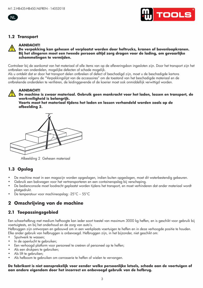
AANDACHT!De machine is zwaar materiaal. Gebruik geen mankracht voor het laden, lossen en transport, de werkveiligheid is belangrijk.Voorts moet het materiaal tijdens het laden en lossen verhandeld worden zoals op de afbeelding 2.
Afbeelding 2 Gehesen materiaal
UUSSEERR‟‟SS MMAANNUUAALL VV11..00 220011440088
- 4 -
1.2. Transport:
Packing can be lifted or moved by lift trucks, cranes or bridge cranes. In case of slinging, a second person must always take care of the load, in order to avoid dangerous oscillations.
During loading and unloading operation, goods must be handled by vehicles or ships.
At the arrival of the goods, verify that all items specified in the delivery notes are included. In case of
missing parts possible defects or damage may due to transport operations.
If finding missing parts, possible defects or damage due to transport, one should examine damaged
cartons according to <<Accessories Packing List>> to verify the condition of damaged goods and
missing parts, also the person in charge or the carrier must be immediately informed.
The machine is heavy goods! Don’t take manpower load and unload and transporting way into consideration, the safety of working is important. Furthermore, during loading and unloading operation goods must be handled as shown in the picture. (Picture 2)
Picture 2 (Goods-lifted)
1.3.Storage:
-The machine equipment should be stocked in the warehouse, if stocked outside should do the disposal
well of waterproof.
-Use box truck in the process of transport, use container storage when shipping.
-The control box should be placed perpendicularly during the transport; and prevent other goods from
extrusion.
-The temperature for machine storage : -25ºC-- 55ºC
2. Manual introduction This manual has been prepared for workshop personnel expert in the use of the lift operator and technicians responsible for routine maintenance fitter.
1.3 Opslag
• De machine moet in een magazijn worden opgeslagen, indien buiten opgeslagen, moet dit waterbestendig gebeuren.• Gebruik een bakwagen voor het vertransporteren en een containeropslag bij verscheping.• De bedienconsole moet loodrecht geplaatst worden tijdens het transport, en moet verhinderen dat ander materiaal wordt
platgedrukt. • De temperatuur voor machineopslag: -25°C – 55°C
2 Omschrijving van de machine
2.1 Toepassingsgebied
Een schaarhefbrug met medium hefhoogte kan ieder soort toestel van maximum 3000 kg heffen, en is geschikt voor gebruik bij voertuigtests, en bij het onderhoud en de zorg van auto’s.Hefbruggen zijn ontworpen en gebouwd om in een werkplaats voertuigen te heffen en in deze verhoogde positie te houden. Elke ander gebruik van hefbruggen is onbevoegd. Hefbruggen zijn, in het bijzonder, niet geschikt om:• Spuitwerk te wassen;• In de openlucht te gebruiken;• Een verhoogd platform voor personeel te creëren of personeel op te heffen;• Als een drukpers te gebruiken;• Als lift te gebruiken;• Als hefboom te gebruiken om carrosserie te heffen of wielen te vervangen.
De fabrikant is niet aansprakelijk voor eender welke persoonlijke letsels, schade aan de voertuigen of aan andere eigendom door het incorrect en onbevoegd gebruik van de hefbrug.
copy
righte
d do
cume
nt - a
ll rig
hts re
serv
ed b
y FB
C
M1.2.HB435-HB450.NLFREN - 14052018
4
NL
2.2 Structuureigenschappen
• Elektrische componenten.• Regelbare afstand tussen de platformen, zodat de hefbrug geschikt is voor verschillende types voertuigen.• Stabiele en betrouwbare werking met kabel anti-breuk beveiliging.• Met tweede geleiderail om een middenkrik toe te voegen.
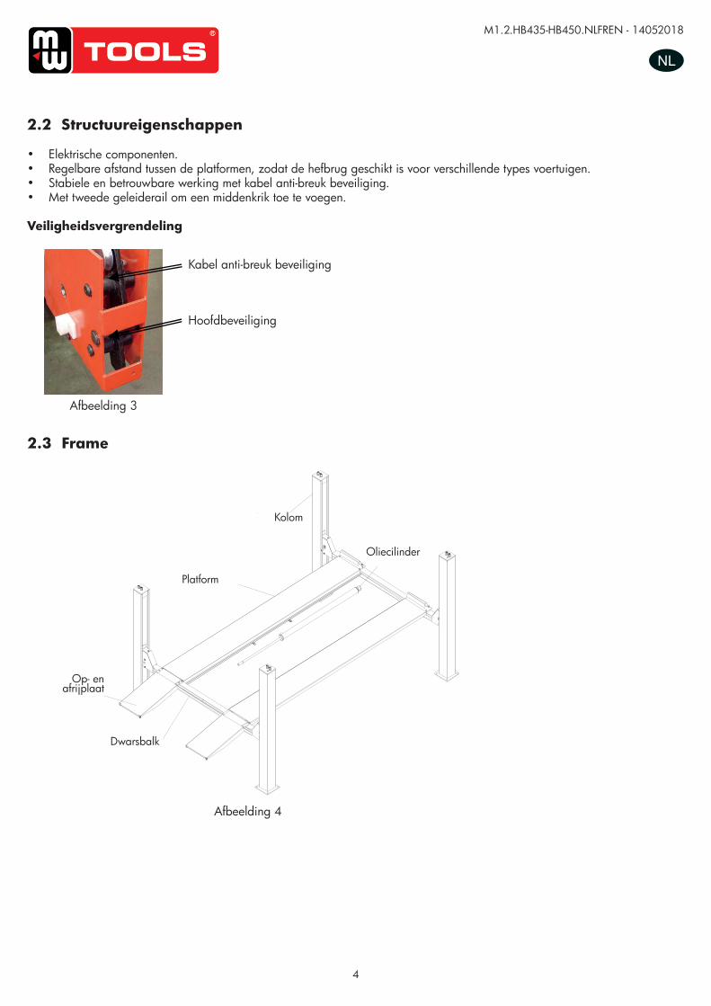
Veiligheidsvergrendeling
Afbeelding 4
Afbeelding 3
UUSSEERR’’SS MMAANNUUAALL VV11..11 220011550099
- 5 -
3.2. Structure Features -imported electric components.
-Adjustable width between two platforms makes the lift more flexible for different vehicles.
-Device performs stable and liable work with anti-breaking rope safety insurance.
-with second lifting trolley guide rail and can add a rolling jack.
Safety lock structure
3.3. Frame
3.4. Power unit
Under the control box is hydraulic oil tank and hydraulic pump, valve and other control system. On the
control box is electrical system.
Picture 3
Insurance structure for rope fracture
Main insurance structure
Picture 4
oil cylinder
column
platform
loadingdock board
crossbeam
Kabel anti-breuk beveiliging
Hoofdbeveiliging
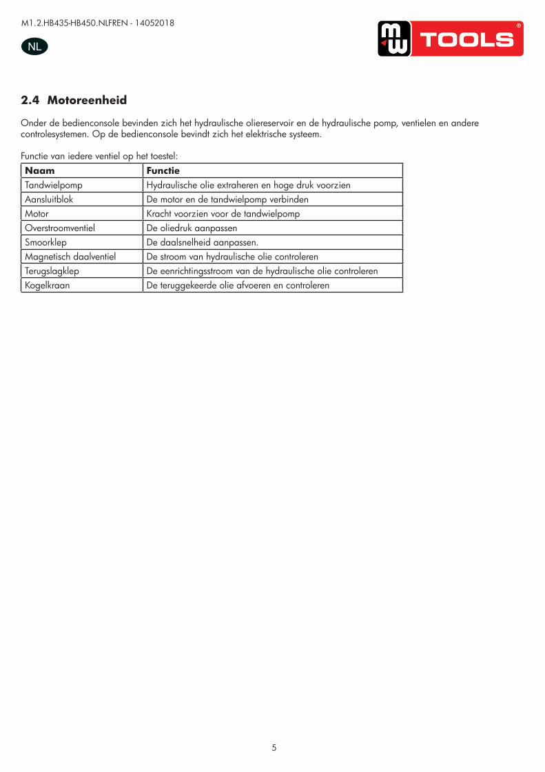
2.3 Frame
UUSSEERR’’SS MMAANNUUAALL VV11..11 220011550099
- 5 -
3.2. Structure Features -imported electric components.
-Adjustable width between two platforms makes the lift more flexible for different vehicles.
-Device performs stable and liable work with anti-breaking rope safety insurance.
-with second lifting trolley guide rail and can add a rolling jack.
Safety lock structure
3.3. Frame
3.4. Power unit
Under the control box is hydraulic oil tank and hydraulic pump, valve and other control system. On the
control box is electrical system.
Picture 3
Insurance structure for rope fracture
Main insurance structure
Picture 4
oil cylinder
column
platform
loadingdock board
crossbeam
Platform
Kolom
Oliecilinder
Dwarsbalk
Op- en afrijplaat
copy
righte
d do
cume
nt - a
ll rig
hts re
serv
ed b
y FB
C
M1.2.HB435-HB450.NLFREN - 14052018
5
NL
2.4 Motoreenheid
Onder de bedienconsole bevinden zich het hydraulische oliereservoir en de hydraulische pomp, ventielen en andere controlesystemen. Op de bedienconsole bevindt zich het elektrische systeem.
Functie van iedere ventiel op het toestel:Naam FunctieTandwielpomp Hydraulische olie extraheren en hoge druk voorzienAansluitblok De motor en de tandwielpomp verbindenMotor Kracht voorzien voor de tandwielpompOverstroomventiel De oliedruk aanpassenSmoorklep De daalsnelheid aanpassen.Magnetisch daalventiel De stroom van hydraulische olie controlerenTerugslagklep De eenrichtingsstroom van de hydraulische olie controlerenKogelkraan De teruggekeerde olie afvoeren en controleren
copy
righte
d do
cume
nt - a
ll rig
hts re
serv
ed b
y FB
C
M1.2.HB435-HB450.NLFREN - 14052018
6
NL
3 Specificaties
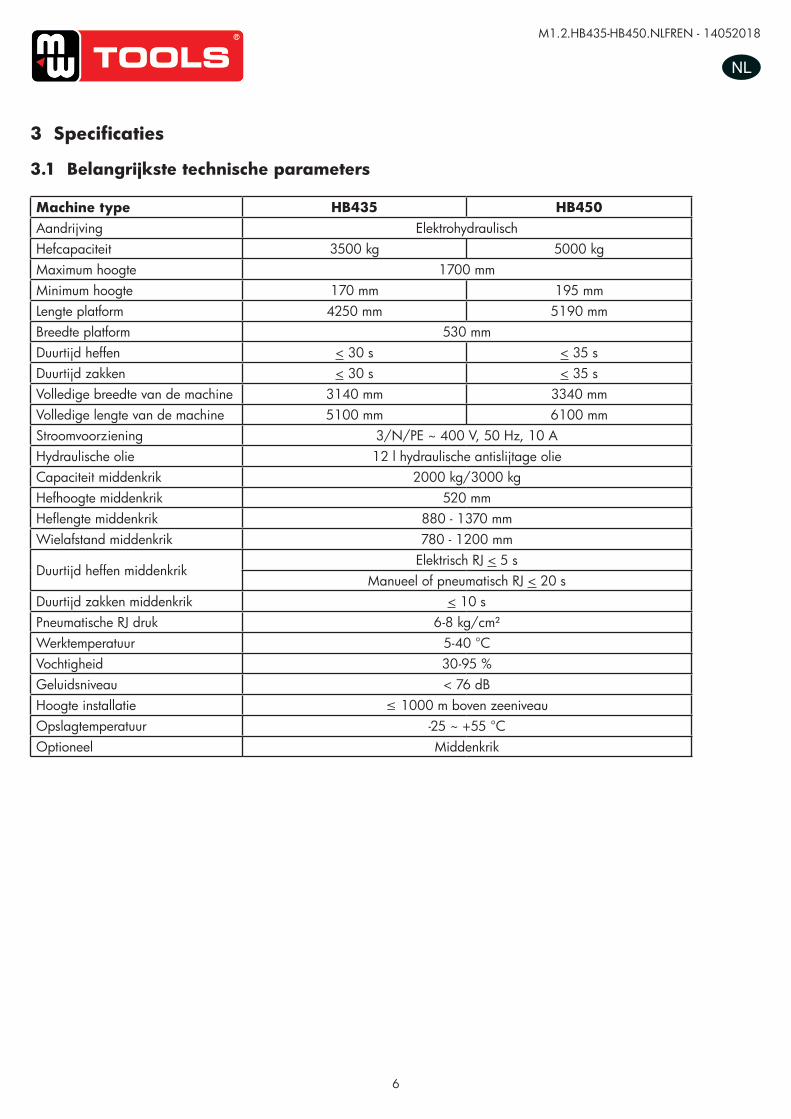
3.1 Belangrijkste technische parameters
Machine type HB435 HB450Aandrijving ElektrohydraulischHefcapaciteit 3500 kg 5000 kgMaximum hoogte 1700 mmMinimum hoogte 170 mm 195 mmLengte platform 4250 mm 5190 mmBreedte platform 530 mmDuurtijd heffen < 30 s < 35 sDuurtijd zakken < 30 s < 35 sVolledige breedte van de machine 3140 mm 3340 mmVolledige lengte van de machine 5100 mm 6100 mmStroomvoorziening 3/N/PE ~ 400 V, 50 Hz, 10 AHydraulische olie 12 l hydraulische antislijtage olieCapaciteit middenkrik 2000 kg/3000 kgHefhoogte middenkrik 520 mmHeflengte middenkrik 880 - 1370 mmWielafstand middenkrik 780 - 1200 mm
Duurtijd heffen middenkrikElektrisch RJ < 5 s
Manueel of pneumatisch RJ < 20 sDuurtijd zakken middenkrik < 10 sPneumatische RJ druk 6-8 kg/cm²Werktemperatuur 5-40 °CVochtigheid 30-95 %Geluidsniveau < 76 dBHoogte installatie ≤ 1000 m boven zeeniveauOpslagtemperatuur -25 ~ +55 °COptioneel Middenkrik
copy
righte
d do
cume
nt - a
ll rig
hts re
serv
ed b
y FB
C
M1.2.HB435-HB450.NLFREN - 14052018
7
NL
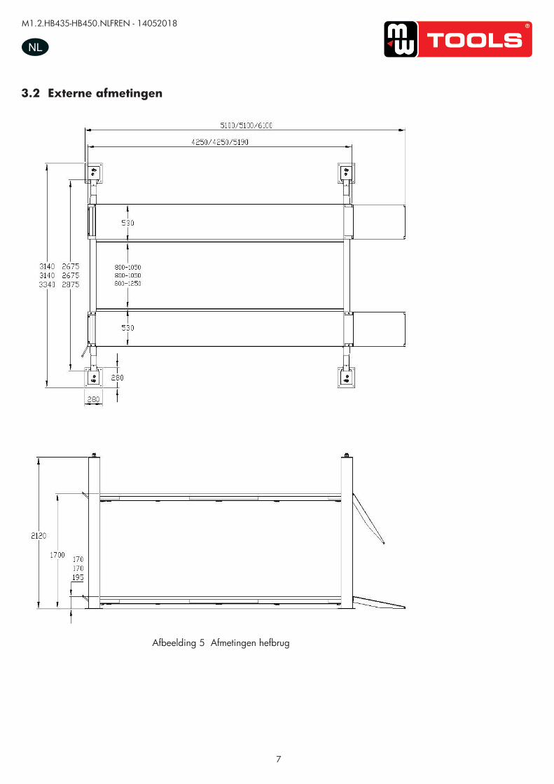
3.2 Externe afmetingen
Afbeelding 5 Afmetingen hefbrug
UUSSEERR’’SS MMAANNUUAALL VV11..11 220011550099
- 7 -
4.2 External dimension drawing
Picture 5(lift dimension picture)
copy
righte
d do
cume
nt - a
ll rig
hts re
serv
ed b
y FB
C
M1.2.HB435-HB450.NLFREN - 14052018
8
NL
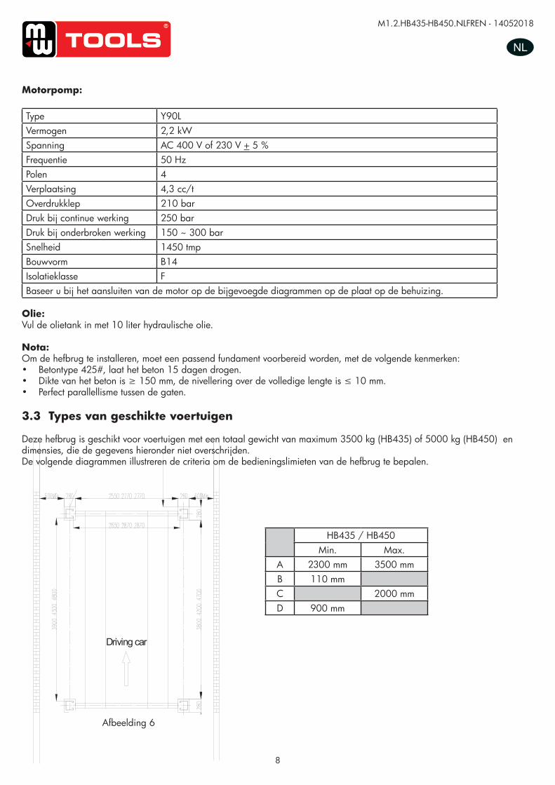
Motorpomp:
Type Y90LVermogen 2,2 kWSpanning AC 400 V of 230 V + 5 %Frequentie 50 HzPolen 4Verplaatsing 4,3 cc/tOverdrukklep 210 barDruk bij continue werking 250 barDruk bij onderbroken werking 150 ~ 300 barSnelheid 1450 tmpBouwvorm B14Isolatieklasse FBaseer u bij het aansluiten van de motor op de bijgevoegde diagrammen op de plaat op de behuizing.
Olie:Vul de olietank in met 10 liter hydraulische olie.
Nota:Om de hefbrug te installeren, moet een passend fundament voorbereid worden, met de volgende kenmerken:• Betontype 425#, laat het beton 15 dagen drogen.• Dikte van het beton is ≥ 150 mm, de nivellering over de volledige lengte is ≤ 10 mm.• Perfect parallellisme tussen de gaten.
3.3 Types van geschikte voertuigen
Deze hefbrug is geschikt voor voertuigen met een totaal gewicht van maximum 3500 kg (HB435) of 5000 kg (HB450) en dimensies, die de gegevens hieronder niet overschrijden. De volgende diagrammen illustreren de criteria om de bedieningslimieten van de hefbrug te bepalen.
Afbeelding 6
HB435 / HB450Min. Max.
A 2300 mm 3500 mmB 110 mmC 2000 mmD 900 mm
UUSSEERR’’SS MMAANNUUAALL VV11..11 220011550099
- 9 -
Driving car
The thickness and leveling of the base concrete are essential and the leveling adjustment ability of the machine itself cannot be relied upon to excessively. Types of vehicle suitable for being lifted and overall dimensions.
4.3. Types of vehicles suitable for
Lift are suitable for virtually all vehicles with total weight of no more than 3500kg/4000kg/5000kg and with
dimensions not exceeding the below data.
The following diagrams illustrate criteria used to define the operating limits of the lift.
Caution: The lower parts of the vehicle underbody could interfere with structural parts of the lift, take particular parts of the sports car.
The lift will also handle customized or non-standard vehicles, provided they are within the maximum specified
carrying capacity.
Also the personnel safety zone must be defined in relation to vehicle with unusual dimensions.
3.5T/4T/5T
Min.(mm) Max.(mm)
A 2300 3500/3500/4500
B 110
C 2000
D 900
Picture 6
copy
righte
d do
cume
nt - a
ll rig
hts re
serv
ed b
y FB
C
M1.2.HB435-HB450.NLFREN - 14052018
9
NL
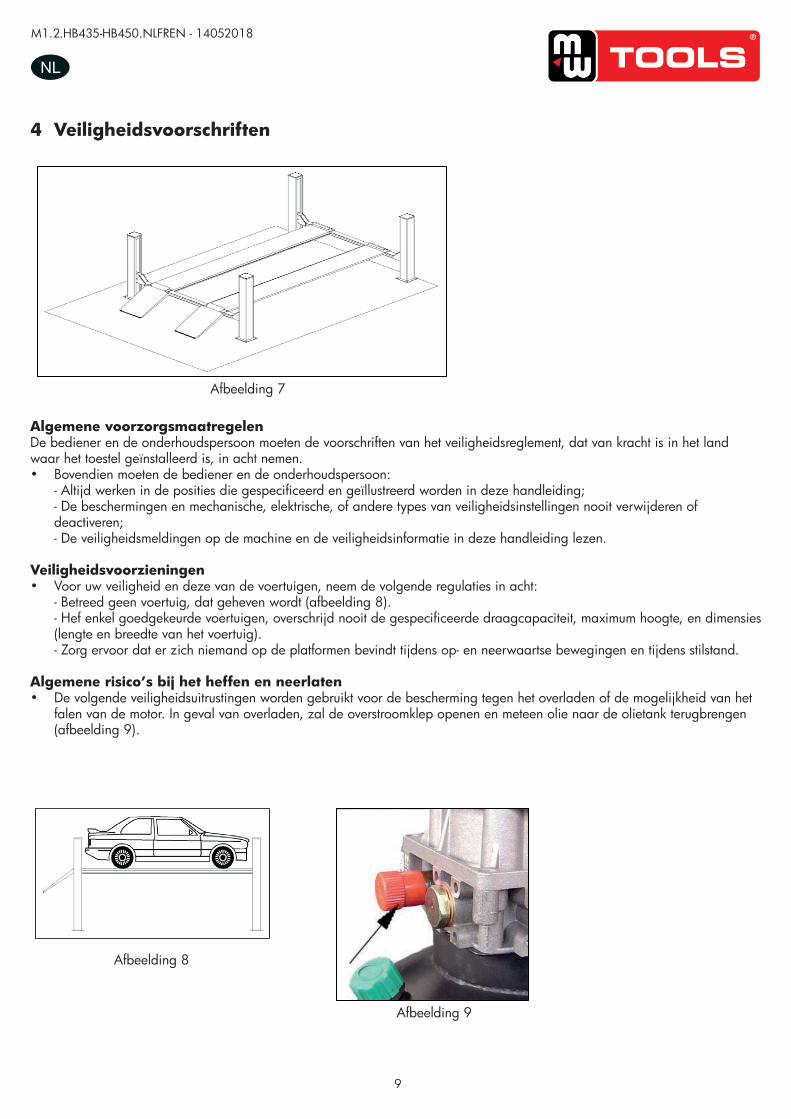
Algemene voorzorgsmaatregelenDe bediener en de onderhoudspersoon moeten de voorschriften van het veiligheidsreglement, dat van kracht is in het land waar het toestel geïnstalleerd is, in acht nemen.• Bovendien moeten de bediener en de onderhoudspersoon:
- Altijd werken in de posities die gespecificeerd en geïllustreerd worden in deze handleiding; - De beschermingen en mechanische, elektrische, of andere types van veiligheidsinstellingen nooit verwijderen of deactiveren; - De veiligheidsmeldingen op de machine en de veiligheidsinformatie in deze handleiding lezen.
Veiligheidsvoorzieningen• Voor uw veiligheid en deze van de voertuigen, neem de volgende regulaties in acht:
- Betreed geen voertuig, dat geheven wordt (afbeelding 8). - Hef enkel goedgekeurde voertuigen, overschrijd nooit de gespecificeerde draagcapaciteit, maximum hoogte, en dimensies (lengte en breedte van het voertuig). - Zorg ervoor dat er zich niemand op de platformen bevindt tijdens op- en neerwaartse bewegingen en tijdens stilstand.
Algemene risico’s bij het heffen en neerlaten• De volgende veiligheidsuitrustingen worden gebruikt voor de bescherming tegen het overladen of de mogelijkheid van het
falen van de motor. In geval van overladen, zal de overstroomklep openen en meteen olie naar de olietank terugbrengen (afbeelding 9).
Afbeelding 8
Afbeelding 9
UUSSEERR’’SS MMAANNUUAALL VV11..11 220011550099
- 11 -
General precautions The operator and the maintenance fitter are required to observe the prescriptions of safety regulation in
force in the country of installation of the lift.
Furthermore, the operator and maintenance fitter must:
-Always work in the stations specified and illustrated in this manual;
-Never remove or deactivate the guards and mechanical, electrical, or other types of safety devices;
-Read the safety notices placed on the machine and the safety information in this manual.
In the manual all safety notices are shown as follows: Warning: indicates following operations that are unsafe and can cause minor injury to persons and
damage the lift, the vehicle or other property.
Risk and protection devices
For optimal personal safety and safety of vehicles, observe the following regulations:
-Do not enter the safety and safety of vehicles is being lifted. (Picture 8)
-Be sure to lift only approved vehicles, never exceed the specified carrying capacity, maximum height,
and projection (vehicle length and width);
-Make sure that there is no person on the platforms during up and down movements and during
standing.(Picture 8)
General risks for lifting or descent The following safety equipments are used to protect over loading or the possibility of engine failure.
In the condition of over loading, the over-falling valve will open and directly return oil to the oil tank.
(Picture 9)
Picture 8
Picture 9
4 Veiligheidsvoorschriften
Afbeelding 7
UUSSEERR’’SS MMAANNUUAALL VV11..11 220011550099
- 10 -
Read this chapter carefully and completely since important information for the safety of the operator or others in case of improper use of the lift is included.
In the following text there are clear explanations regarding certain situations of risk or danger that may
arise during the operation or maintenance of the lift, the safety device installed and the correct use of
such systems, residual risks and operative procedures to use (general specific precautions to eliminate
potential hazards).
Lifts are designed and built to lift vehicles and hold them in the elevated position in an enclosed workshop. All other uses of the lifts are unauthorized. In particular, the lifts are not suitable for: -Washing spray work; -Use in outdoors; -Creating raised platforms for personnel or lifting personnel; -Use as a press for crushing purposes; -Use as elevator; -Use as a lift jack for lifting vehicle bodies or changing wheels.
The manufacturer is not liable for any injury to persons or damage to vehicles and other property caused
by the incorrect and unauthorized use of the lifts.
During lifting and descent, the operator must remain in the control station as the diagrams illustrated.
As the diagrams illustrated, the presence of persons inside the danger zone indicated is strictly
prohibited. During operations persons are admitted to the area beneath the vehicle only when the vehicle
is already in the elevated position, when the platforms are stationary, and when the mechanical safety
devices are firmly engaged (e.g.: the safety gear is completely locked).
Do not use the lift without protection devices or with the protection devices inhibited.
Failure to comply with this regulation can cause serious injury to persons, and irreparable damage to the
lift and the vehicle being lifted.
5. Safety
Picture 7
copy
righte
d do
cume
nt - a
ll rig
hts re
serv
ed b
y FB
C
M1.2.HB435-HB450.NLFREN - 14052018
10
NL
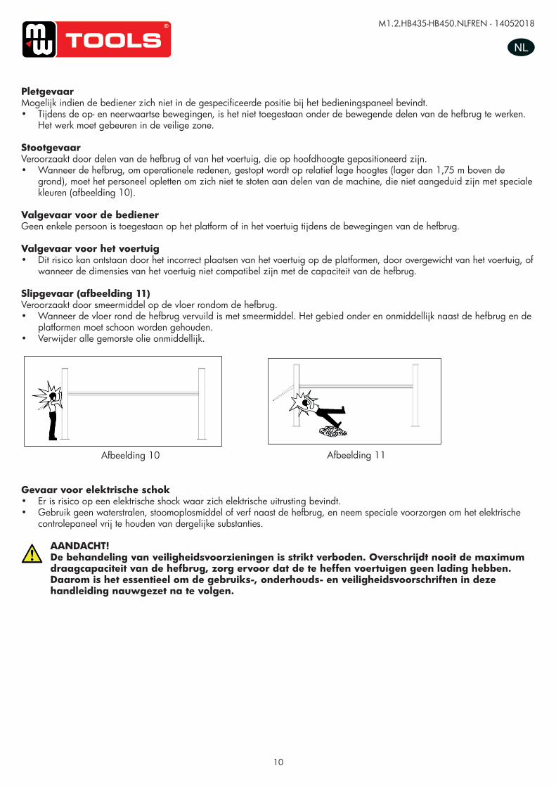
Afbeelding 11Afbeelding 10
PletgevaarMogelijk indien de bediener zich niet in de gespecificeerde positie bij het bedieningspaneel bevindt.• Tijdens de op- en neerwaartse bewegingen, is het niet toegestaan onder de bewegende delen van de hefbrug te werken.
Het werk moet gebeuren in de veilige zone.
StootgevaarVeroorzaakt door delen van de hefbrug of van het voertuig, die op hoofdhoogte gepositioneerd zijn.• Wanneer de hefbrug, om operationele redenen, gestopt wordt op relatief lage hoogtes (lager dan 1,75 m boven de
grond), moet het personeel opletten om zich niet te stoten aan delen van de machine, die niet aangeduid zijn met speciale kleuren (afbeelding 10).
Valgevaar voor de bedienerGeen enkele persoon is toegestaan op het platform of in het voertuig tijdens de bewegingen van de hefbrug.
Valgevaar voor het voertuig• Dit risico kan ontstaan door het incorrect plaatsen van het voertuig op de platformen, door overgewicht van het voertuig, of
wanneer de dimensies van het voertuig niet compatibel zijn met de capaciteit van de hefbrug.
Slipgevaar (afbeelding 11)Veroorzaakt door smeermiddel op de vloer rondom de hefbrug.• Wanneer de vloer rond de hefbrug vervuild is met smeermiddel. Het gebied onder en onmiddellijk naast de hefbrug en de
platformen moet schoon worden gehouden. • Verwijder alle gemorste olie onmiddellijk.
Gevaar voor elektrische schok• Er is risico op een elektrische shock waar zich elektrische uitrusting bevindt.• Gebruik geen waterstralen, stoomoplosmiddel of verf naast de hefbrug, en neem speciale voorzorgen om het elektrische
controlepaneel vrij te houden van dergelijke substanties.
AANDACHT!De behandeling van veiligheidsvoorzieningen is strikt verboden. Overschrijdt nooit de maximum draagcapaciteit van de hefbrug, zorg ervoor dat de te heffen voertuigen geen lading hebben.Daarom is het essentieel om de gebruiks-, onderhouds- en veiligheidsvoorschriften in deze handleiding nauwgezet na te volgen.
UUSSEERR’’SS MMAANNUUAALL VV11..11 220011550099
- 12 -
Risk of crushing Possible if the operator controlling the lift is not I the specified position at the control panel.
When the platforms (and vehicle) are lowering the operator must never be partly or completely underneath the
movable structure. Always remain in the control zone.
Risk of impact (Picture 10) Caused by the parts of the lift or the vehicle that is positioned at head height.
When, due to operational reasons, the lift is stopped at relatively low elevations personnel must be careful to avoid
impact with parts of the machine not marked with special color.
Risk of operator falling No person is permitted in the platform or in the vehicle when the lift lifting and lowing,
Risk of vehicle falling from lift This hazard may cause of incorrect positioning of the vehicle on the platforms, incorrect stopping of the vehicle, or
vehicles of dimensions that are not compatible with the capacity of the lift.
Never attempt to perform test by driving the vehicle while it is on the platforms Never leave objects in the lowering area of the movable parts of the lift.
Risk of slipping(Picture 11) Caused by lubricant contamination of the floor around the lift.
The area beneath and immediately surrounding the lift and also the platforms must be kept clean.
Remove any oil spills immediately.
Picture 10
Picture 11
copy
righte
d do
cume
nt - a
ll rig
hts re
serv
ed b
y FB
C
M1.2.HB435-HB450.NLFREN - 14052018
11
NL
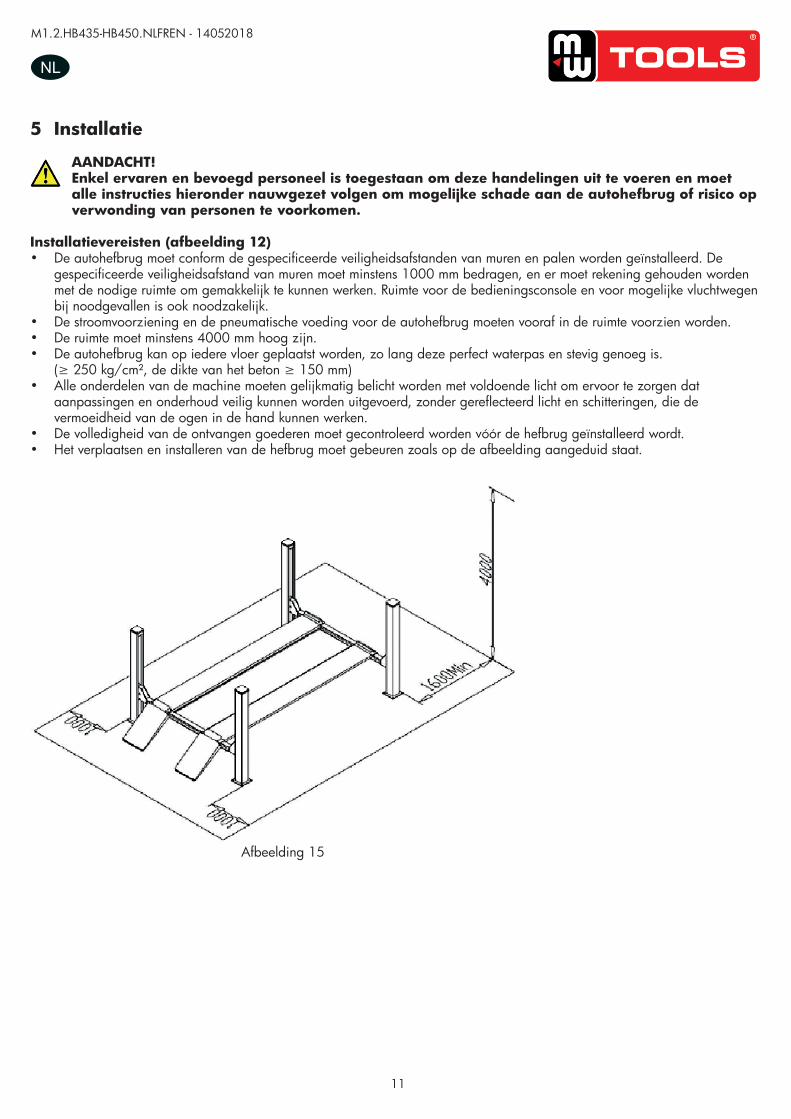
5 Installatie
AANDACHT!Enkel ervaren en bevoegd personeel is toegestaan om deze handelingen uit te voeren en moet alle instructies hieronder nauwgezet volgen om mogelijke schade aan de autohefbrug of risico op verwonding van personen te voorkomen.
Installatievereisten (afbeelding 12)• De autohefbrug moet conform de gespecificeerde veiligheidsafstanden van muren en palen worden geïnstalleerd. De
gespecificeerde veiligheidsafstand van muren moet minstens 1000 mm bedragen, en er moet rekening gehouden worden met de nodige ruimte om gemakkelijk te kunnen werken. Ruimte voor de bedieningsconsole en voor mogelijke vluchtwegen bij noodgevallen is ook noodzakelijk.
• De stroomvoorziening en de pneumatische voeding voor de autohefbrug moeten vooraf in de ruimte voorzien worden.• De ruimte moet minstens 4000 mm hoog zijn.• De autohefbrug kan op iedere vloer geplaatst worden, zo lang deze perfect waterpas en stevig genoeg is.
(≥ 250 kg/cm², de dikte van het beton ≥ 150 mm)• Alle onderdelen van de machine moeten gelijkmatig belicht worden met voldoende licht om ervoor te zorgen dat
aanpassingen en onderhoud veilig kunnen worden uitgevoerd, zonder gereflecteerd licht en schitteringen, die de vermoeidheid van de ogen in de hand kunnen werken.
• De volledigheid van de ontvangen goederen moet gecontroleerd worden vóór de hefbrug geïnstalleerd wordt. • Het verplaatsen en installeren van de hefbrug moet gebeuren zoals op de afbeelding aangeduid staat.
Afbeelding 15
UUSSEERR’’SS MMAANNUUAALL VV11..11 220011550099
- 13 -
Risk of electric shock Risk of electric shock in areas of the lift housing electrical wiring.
Do not use jets of water, steam solvents or paint next to the lift, and take special care to keep such substances
clear of the electrical control panel.
The handling of safety devices is strictly forbidden. Never exceed the maximum carrying capacity of the lift, make sure the vehicles to be lifted have no load. It is therefore essential to adhere scrupulously to all regulations regarding use, maintenance and safety contained in this manual.
6. Installation
Skilled and authorized personnel only should be allowed to perform these operations, follow all instructions shown below carefully, in order to prevent possible damage to the car lift or risk of injury to people.
Installation requirements (Picture 12) The car lift must be installed according to the specified safety distances from walls must be 1000 mm at least,
taking into consideration of the necessary space to work easily. Further space for the control site and for possible
runways in case of emergency is also necessary; the room must be previously arranged for the power supply and
pneumatic feed of the car lift. The room must be 4000 mm in height, at least, the car lift can be placed on any floor,
as long as it is perfectly level and sufficiently resistant.(≥250kg/cm2)
-All parts of the machine must be uniformly lit with sufficient light to make sure that the adjustment and
maintenance operations specified in the manual can be performed safely, and without areas of shadow, reflected
light, glare and avoiding all situations that could give rise to eye fatigue.
-The lighting must be installed in accordance with the laws in force in the place of installation.
-the thickness and leveling of the base concrete are essential
-thickness of concrete≥150mm, the leveling of whole length≤10mm.
Picture 12
copy
righte
d do
cume
nt - a
ll rig
hts re
serv
ed b
y FB
C

M1.2.HB435-HB450.NLFREN - 14052018
12
NLUUSSEERR’’SS MMAANNUUAALL VV11..11 220011550099
- 14 -
Installation scheme for four post lift
Picture 13
Motoreenheid
Subbalk
Rijrichting
Uitlijnen van de vier wielen
Hoofd- balk
Afbeelding 13
copy
righte
d do
cume
nt - a
ll rig
hts re
serv
ed b
y FB
C
M1.2.HB435-HB450.NLFREN - 14052018
13
NL
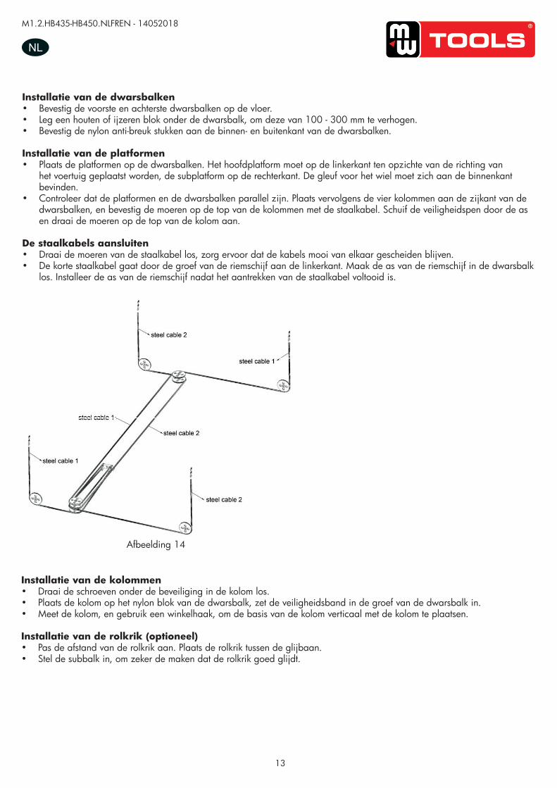
Afbeelding 14
Installatie van de dwarsbalken• Bevestig de voorste en achterste dwarsbalken op de vloer.• Leg een houten of ijzeren blok onder de dwarsbalk, om deze van 100 - 300 mm te verhogen.• Bevestig de nylon anti-breuk stukken aan de binnen- en buitenkant van de dwarsbalken.
Installatie van de platformen• Plaats de platformen op de dwarsbalken. Het hoofdplatform moet op de linkerkant ten opzichte van de richting van
het voertuig geplaatst worden, de subplatform op de rechterkant. De gleuf voor het wiel moet zich aan de binnenkant bevinden.
• Controleer dat de platformen en de dwarsbalken parallel zijn. Plaats vervolgens de vier kolommen aan de zijkant van de dwarsbalken, en bevestig de moeren op de top van de kolommen met de staalkabel. Schuif de veiligheidspen door de as en draai de moeren op de top van de kolom aan.
De staalkabels aansluiten• Draai de moeren van de staalkabel los, zorg ervoor dat de kabels mooi van elkaar gescheiden blijven.• De korte staalkabel gaat door de groef van de riemschijf aan de linkerkant. Maak de as van de riemschijf in de dwarsbalk
los. Installeer de as van de riemschijf nadat het aantrekken van de staalkabel voltooid is.
UUSSEERR’’SS MMAANNUUAALL VV11..11 220011550099
- 15 -
Crossbeam installation -fix the front and back crossbeam on the floor.
-Put a wood or an iron under the crossbeam in order to raise 100-300mm.
-fix eight nylon anti-crashes inner and outer of the crossbeam.
Platform installation: -Put two platforms on the transom, the main platform should located on the left side of the moving vehicle direction,
the sub-platform located on the right side, the rolling wheel notch on the platform should inside.
-check two platforms and the diagonal of two transom are straight, then put four posts on the side of the transom,
and fix the nuts on the roof of the post with steel cable, put the safety teeth trough the limit axis, also fix the nuts on
the roof of the post.
Steel cable connection: -Unload the nuts of the steel cable, avoid the steel cables being twining with each other.
- The short steel cable goes through the groove of pulley on the left side. Loose the shaft of pulley inside the
crossbeam. Install the shaft of pulley after finishing putting on the steel cable.
Post installation: -Unload the screws under the insurance in the post.
-stick the column on the nylon block of the crossbeam, insert the insurance strip into the groove of crossbeam
-measuring the column and use the thick iron mat to make the column base plate vertical with the column.
Rolling jack installation(optional part):
-adjust the distance of the rolling jack; put the rolling jack between the slide track.
-adjust the sub beam to make sure the sliding of the rolling jack.
Picture 14
Installatie van de kolommen• Draai de schroeven onder de beveiliging in de kolom los.• Plaats de kolom op het nylon blok van de dwarsbalk, zet de veiligheidsband in de groef van de dwarsbalk in.• Meet de kolom, en gebruik een winkelhaak, om de basis van de kolom verticaal met de kolom te plaatsen.
Installatie van de rolkrik (optioneel)• Pas de afstand van de rolkrik aan. Plaats de rolkrik tussen de glijbaan.• Stel de subbalk in, om zeker de maken dat de rolkrik goed glijdt.
copy
righte
d do
cume
nt - a
ll rig
hts re
serv
ed b
y FB
C
M1.2.HB435-HB450.NLFREN - 14052018
14
NL
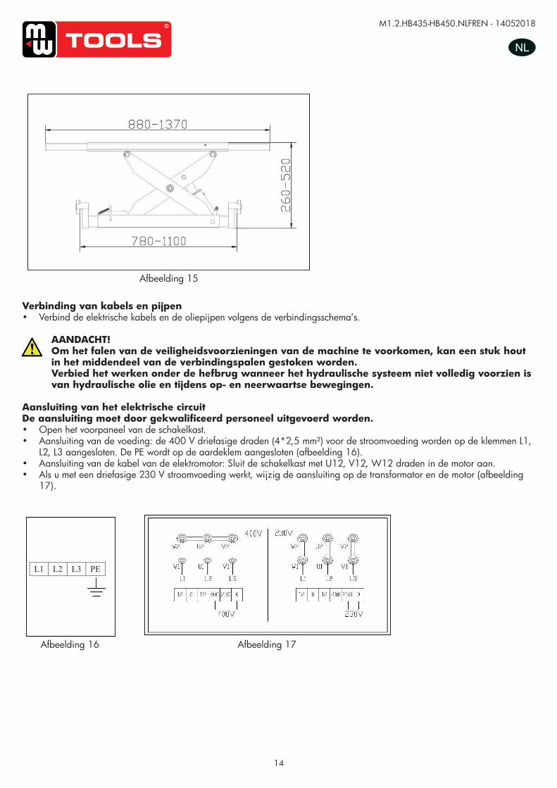
Verbinding van kabels en pijpen• Verbind de elektrische kabels en de oliepijpen volgens de verbindingsschema’s.
AANDACHT!Om het falen van de veiligheidsvoorzieningen van de machine te voorkomen, kan een stuk hout in het middendeel van de verbindingspalen gestoken worden.Verbied het werken onder de hefbrug wanneer het hydraulische systeem niet volledig voorzien is van hydraulische olie en tijdens op- en neerwaartse bewegingen.
Aansluiting van het elektrische circuitDe aansluiting moet door gekwalificeerd personeel uitgevoerd worden.• Open het voorpaneel van de schakelkast.• Aansluiting van de voeding: de 400 V driefasige draden (4*2,5 mm²) voor de stroomvoeding worden op de klemmen L1,
L2, L3 aangesloten. De PE wordt op de aardeklem aangesloten (afbeelding 16).• Aansluiting van de kabel van de elektromotor: Sluit de schakelkast met U12, V12, W12 draden in de motor aan.• Als u met een driefasige 230 V stroomvoeding werkt, wijzig de aansluiting op de transformator en de motor (afbeelding
17).
UUSSEERR’’SS MMAANNUUAALL VV11..11 220011550099
- 16 -
Line connection Connect the electrical and oil line according to the electric wiring diagram and oil line connection
To avoid the unexpected lift closure due to mechanical safety device release insert wooden pieces in the inner part of the base frame. Pay attention not to work under the lift until the hydraulic system has not been completely filled with hydraulic oil.
Electrical circuit connection:
According to the electric connection.
Skilled personnel only are allowed to perform the operations shown below.
-open the control box front cover
-connection of power supply: the 400 three-phase five-wires (4*2.5mm2) for power supply are connected to
terminals 1#, 2#, 3#.The PE is connected to the ground wire.(Picture 16)
-Electric motor wire connection: connect the control box with U12﹟、V12#、W12# electric wire to motor wire box.
-therefore if you wish the lift to operate at 230V three-phase, change the connection on the transformer and motor.
(Picture 17)
.
L1 L2 L3 PE
Picture 15
Picture 16 Picture 17
Afbeelding 15
UUSSEERR’’SS MMAANNUUAALL VV11..11 220011550099
- 16 -
Line connection Connect the electrical and oil line according to the electric wiring diagram and oil line connection
To avoid the unexpected lift closure due to mechanical safety device release insert wooden pieces in the inner part of the base frame. Pay attention not to work under the lift until the hydraulic system has not been completely filled with hydraulic oil.
Electrical circuit connection:
According to the electric connection.
Skilled personnel only are allowed to perform the operations shown below.
-open the control box front cover
-connection of power supply: the 400 three-phase five-wires (4*2.5mm2) for power supply are connected to
terminals 1#, 2#, 3#.The PE is connected to the ground wire.(Picture 16)
-Electric motor wire connection: connect the control box with U12﹟、V12#、W12# electric wire to motor wire box.
-therefore if you wish the lift to operate at 230V three-phase, change the connection on the transformer and motor.
(Picture 17)
.
L1 L2 L3 PE
Picture 15
Picture 16 Picture 17 Afbeelding 16 Afbeelding 17
copy
righte
d do
cume
nt - a
ll rig
hts re
serv
ed b
y FB
C
M1.2.HB435-HB450.NLFREN - 14052018
15
NL
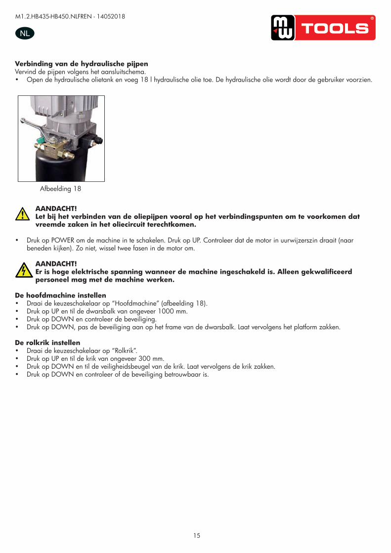
Verbinding van de hydraulische pijpenVervind de pijpen volgens het aansluitschema.• Open de hydraulische olietank en voeg 18 l hydraulische olie toe. De hydraulische olie wordt door de gebruiker voorzien.
AANDACHT!Let bij het verbinden van de oliepijpen vooral op het verbindingspunten om te voorkomen dat vreemde zaken in het oliecircuit terechtkomen.
• Druk op POWER om de machine in te schakelen. Druk op UP. Controleer dat de motor in uurwijzerszin draait (naar beneden kijken). Zo niet, wissel twee fasen in de motor om.
AANDACHT!Er is hoge elektrische spanning wanneer de machine ingeschakeld is. Alleen gekwalificeerd personeel mag met de machine werken.
De hoofdmachine instellen• Draai de keuzeschakelaar op “Hoofdmachine” (afbeelding 18).• Druk op UP en til de dwarsbalk van ongeveer 1000 mm.• Druk op DOWN en controleer de beveiliging.• Druk op DOWN, pas de beveiliging aan op het frame van de dwarsbalk. Laat vervolgens het platform zakken.
De rolkrik instellen• Draai de keuzeschakelaar op “Rolkrik”.• Druk op UP en til de krik van ongeveer 300 mm.• Druk op DOWN en til de veiligheidsbeugel van de krik. Laat vervolgens de krik zakken.• Druk op DOWN en controleer of de beveiliging betrouwbaar is.
UUSSEERR’’SS MMAANNUUAALL VV11..11 220011550099
- 17 -
Hydraulic hoses connection:
Follow <<oil hose connection diagram >> to connect the hydraulic oil hoses
Open the hydraulic oil tank, add 18L of hydraulic oil into the oil tank, the hydraulic oil is provided by the user.
Make sure the clean of hydraulic oil, prevent any impurity into the oil line, lead the digest of the oil line and no working of the solenoid valve. -press the “power” button to turn on power, clicking the “up” button, check whether the motor turns clockwise
(looking downward), if not press “power” button, change the phase of the motor.
When turn on power, there is high voltage in the control box, only authorized person can operate.
Main machine adjustment -Turn the selector switch to the “main” position. (Picture18)
-press “up” button SB1, lift crossbeam approximately 1000mm.
-press “down” button SB2, verity the safety instruction.
-press “down” button SB2, adjust the safety instruction on the frame of the crossbeam. Then lower the platform.
Rolling jack adjustment -turn the selector switch to “rolling jack” position.
-press “up” button SB1, lift approximately 300mm.
-press “down” button SB2 and lift the safety rod of rolling jack, lower the rolling jack.
-press “down” button SB2, verify the safety instruction is reliable.
Picture 18 Afbeelding 18
copy
righte
d do
cume
nt - a
ll rig
hts re
serv
ed b
y FB
C
M1.2.HB435-HB450.NLFREN - 14052018
16
NL
UUSSEERR‟‟SS MMAANNUUAALL VV11..00 220011440088
- 15 -
Platform Installation:
-Place two lift platforms on the position of the location
-The bottom of oil cylinder is located in the frontage of machine (the direction of getting on the vehicle)
-Use fork car or other lifting equipments to lift the platform (Picture17) and make sure that the safety
equipment of machine is both turned on and locked.
Picture 17
To avoid failure of machine safety equipment, can insert a wood in the middle part of joint-pole. Prohibit working beneath the lift when hydraulic system is not completely equipped with hydraulic oil and take the action of up and down operations. -When moving the lift platform, adjust the space between two platforms; make sure that the two platforms are parallel.
Ground bolts installation
The ground bolts installation must start after the expiry date on the maintenance of concert, otherwise, it
will affect the quality of solidity.
-Adjust the parallel of the platform and the distance of two platform as Picture 18 requires.
-Fix the anchor bolts with a percussion electric drill (percussion drill bit is of 16), drill to 120mm hole and
clean the hole.(Picture 18) -Use light hammer to install the ground bolts into the hole (need not install the central expanded nail of
ground bolts, install it after level adjustment.) (Picture 19)
Picture 18 Picture 19 Picture 20
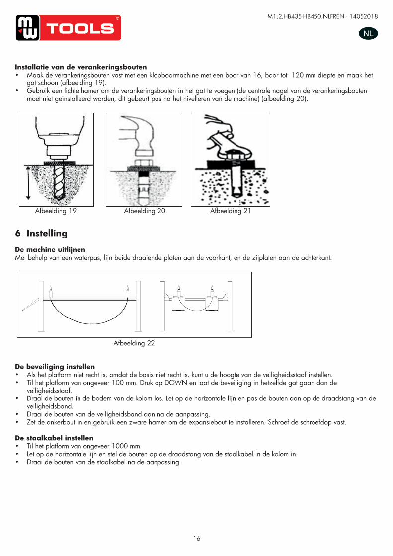
Installatie van de verankeringsbouten• Maak de verankeringsbouten vast met een klopboormachine met een boor van 16, boor tot 120 mm diepte en maak het
gat schoon (afbeelding 19).• Gebruik een lichte hamer om de verankeringsbouten in het gat te voegen (de centrale nagel van de verankeringsbouten
moet niet geïnstalleerd worden, dit gebeurt pas na het nivelleren van de machine) (afbeelding 20).
Afbeelding 19 Afbeelding 20 Afbeelding 21
Afbeelding 22
UUSSEERR’’SS MMAANNUUAALL VV11..11 220011550099
- 18 -
Anchor bolts installation -Fix the anchor bolts with a percussion electric drill (percussion drill bit is of 16), drill to 120mm hole and
clean the hole.(Picture 20) -Use light hammer to install the ground bolts into the hole (need not install the central expanded nail of
ground bolts, install it after level adjustment.) (Picture 21)
7. Adjustment
Level adjustment (Picture 23)
-adjust the level of the two front turntable and the slide plates on both sides at back with a leveling instrument.
Insurance level adjustment.
-if the unparallel of the basement lead to the unparallel of the platform, can adjust the height of the safety rod.
-lift the platform approximately 100mm; press “down” button let the insurance go into the same hole of insurance
rod.
-loose the bolts on the bottom of column, observe the horizontal line and adjust the bolts on the insurance strip
thread rod
-fix the insurance strip bolts and nuts after level adjustment.
-insert the anchor, use a heavy hammer to install the expansion bolts and screw down the screw cap
Steel cable adjustment
-lift the platform approximately 1000mm.
-observe the horizontal line and adjust the bolts on the steel cable thread rod inside the column.
-fix the steel cable bolts after level adjustment.
Picture 20 Picture 21
Picture 23
Picture 22
6 Instelling
De machine uitlijnenMet behulp van een waterpas, lijn beide draaiende platen aan de voorkant, en de zijplaten aan de achterkant.
De beveiliging instellen• Als het platform niet recht is, omdat de basis niet recht is, kunt u de hoogte van de veiligheidsstaaf instellen. • Til het platform van ongeveer 100 mm. Druk op DOWN en laat de beveiliging in hetzelfde gat gaan dan de
veiligheidsstaaf.• Draai de bouten in de bodem van de kolom los. Let op de horizontale lijn en pas de bouten aan op de draadstang van de
veiligheidsband.• Draai de bouten van de veiligheidsband aan na de aanpassing.• Zet de ankerbout in en gebruik een zware hamer om de expansiebout te installeren. Schroef de schroefdop vast.
De staalkabel instellen• Til het platform van ongeveer 1000 mm.• Let op de horizontale lijn en stel de bouten op de draadstang van de staalkabel in de kolom in.• Draai de bouten van de staalkabel na de aanpassing.
copy
righte
d do
cume
nt - a
ll rig
hts re
serv
ed b
y FB
C
M1.2.HB435-HB450.NLFREN - 14052018
17
NL
7 Bediening
AANDACHT!Enkel bekwaam en geoefend personeel mag de bediening uitvoeren. Volg de volgende procedures.
Vóór de bediening:• Verwijder de obstakels rond de hefbrug vóór de bediening.• Let op de synchronisatie en de kalmte van het heffen.• Controleer of de veiligheidsklem soepel en betrouwbaar is.• Controleer of de hefbrug automatisch zal stoppen bij het bereiken van z’n hoogste positie.• Controleer of er geen luchtlek is in de solenoïdeklep, in de luchtcilinder, in de luchtpijp en in de verbinding.• Controleer of het geluid van de motor en de tandradpomp in werking normaal is.• Controleer of het te heffen voertuig of andere goederen de capaciteit van de hefbrug niet overschrijden.
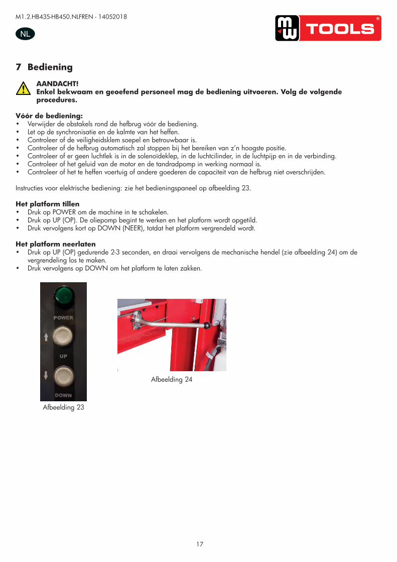
Instructies voor elektrische bediening: zie het bedieningspaneel op afbeelding 23.
Het platform tillen• Druk op POWER om de machine in te schakelen.• Druk op UP (OP). De oliepomp begint te werken en het platform wordt opgetild.• Druk vervolgens kort op DOWN (NEER), totdat het platform vergrendeld wordt.
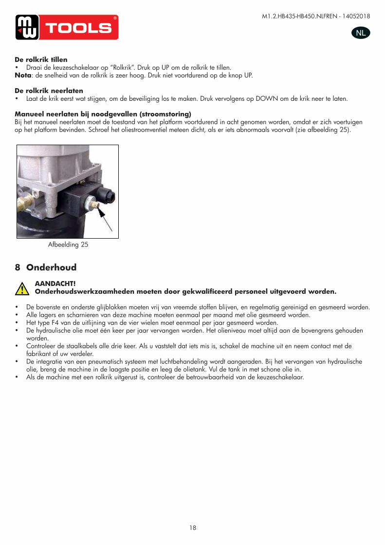
Het platform neerlaten• Druk op UP (OP) gedurende 2-3 seconden, en draai vervolgens de mechanische hendel (zie afbeelding 24) om de
vergrendeling los te maken. • Druk vervolgens op DOWN om het platform te laten zakken.
Afbeelding 23
Afbeelding 24
copy
righte
d do
cume
nt - a
ll rig
hts re
serv
ed b
y FB
C
M1.2.HB435-HB450.NLFREN - 14052018
18
NL
De rolkrik tillen• Draai de keuzeschakelaar op “Rolkrik”. Druk op UP om de rolkrik te tillen.Nota: de snelheid van de rolkrik is zeer hoog. Druk niet voortdurend op de knop UP.
De rolkrik neerlaten• Laat de krik eerst wat stijgen, om de beveiliging los te maken. Druk vervolgens op DOWN om de krik neer te laten.
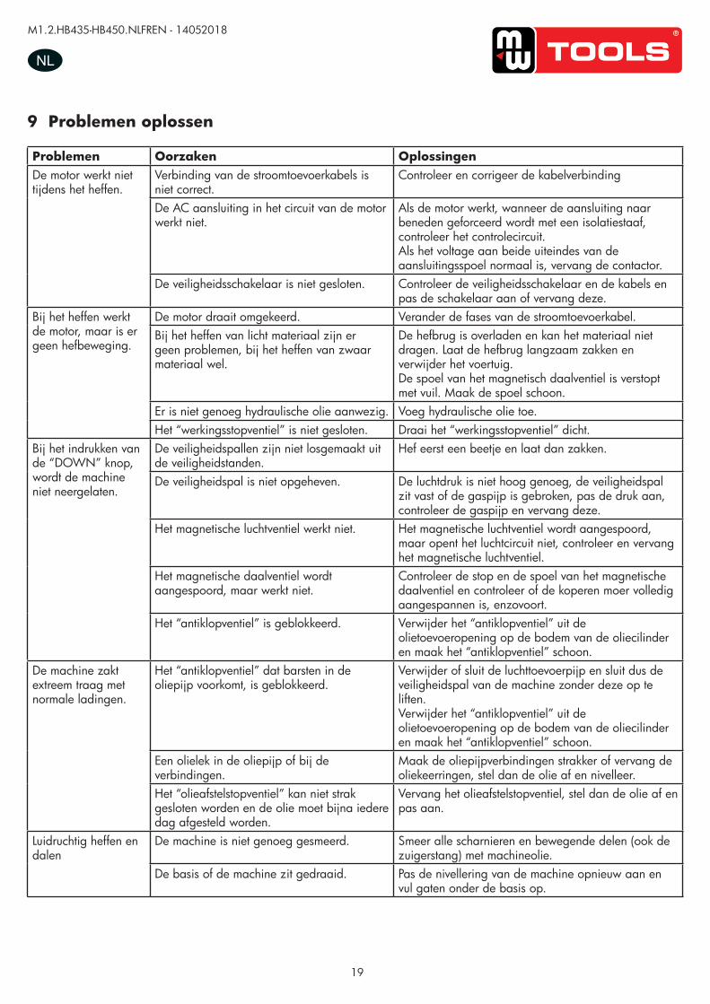
Manueel neerlaten bij noodgevallen (stroomstoring)Bij het manueel neerlaten moet de toestand van het platform voortdurend in acht genomen worden, omdat er zich voertuigen op het platform bevinden. Schroef het oliestroomventiel meteen dicht, als er iets abnormaals voorvalt (zie afbeelding 25).
UUSSEERR’’SS MMAANNUUAALL VV11..11 220011550099
- 20 -
Only authorized person can operate, doing alignment only after “locking” process.
Ordinary rolling jack lifting -turn the selector switch on “rolling jack” position, clicking “up” button, rolling jack is lift.
Note: the speed of rolling jack is fast, cannot press “up” button continuously.
Ordinary rolling jack lowering -First lift the rolling jack a little, lift up the insurance of rolling jack, press the “down” button to lower the lift
Emergency manual operation for lowering (power failure) When lowering through manual operation, should observe the condition of platform at any time because
there are vehicles on the platform. If there is something abnormal, screw down oil loop valve
immediately.(refer to Picture 26)
The process of manual operation
9.Maintenance and care The maintenance and care of the lift must be operated by skilled person.
-the upper and lower sliding blocks must be cleared of foreign objects, and must be kept clean and lubricated. -all bearings and hinges on this machine must be lubricated once a month
-the type of F4 of the four-wheel alignment should lubricate yearly.
-the hydraulic oil must be replaced one time each year. The oil level should always be kept at upper limit position.
-check the steel line every three times and if there is something wrong, stop using, and tell the manufacture.
-the integration of the pneumatic system with an air treatment unit is suggested.
When change hydraulic oil, put machines to the lowest position, have the oil tank empty, when add new oil, should
have the oil cleaned.
-if equipped with rolling jack, check the liability of the switch.
Picture 26 Afbeelding 25
8 Onderhoud
AANDACHT!Onderhoudswerkzaamheden moeten door gekwalificeerd personeel uitgevoerd worden.
• De bovenste en onderste glijblokken moeten vrij van vreemde stoffen blijven, en regelmatig gereinigd en gesmeerd worden.• Alle lagers en scharnieren van deze machine moeten eenmaal per maand met olie gesmeerd worden.• Het type F4 van de uitlijning van de vier wielen moet eenmaal per jaar gesmeerd worden.• De hydraulische olie moet één keer per jaar vervangen worden. Het olieniveau moet altijd aan de bovengrens gehouden
worden.• Controleer de staalkabels alle drie keer. Als u vaststelt dat iets mis is, schakel de machine uit en neem contact met de
fabrikant of uw verdeler.• De integratie van een pneumatisch systeem met luchtbehandeling wordt aangeraden. Bij het vervangen van hydraulische
olie, breng de machine in de laagste positie en leeg de olietank. Vul de tank in met schone olie in.• Als de machine met een rolkrik uitgerust is, controleer de betrouwbaarheid van de keuzeschakelaar.
copy
righte
d do
cume
nt - a
ll rig
hts re
serv
ed b
y FB
C
M1.2.HB435-HB450.NLFREN - 14052018
19
NL
9 Problemen oplossen
Problemen Oorzaken OplossingenDe motor werkt niet tijdens het heffen.
Verbinding van de stroomtoevoerkabels is niet correct.
Controleer en corrigeer de kabelverbinding
De AC aansluiting in het circuit van de motor werkt niet.
Als de motor werkt, wanneer de aansluiting naar beneden geforceerd wordt met een isolatiestaaf, controleer het controlecircuit.Als het voltage aan beide uiteindes van de aansluitingsspoel normaal is, vervang de contactor.
De veiligheidsschakelaar is niet gesloten. Controleer de veiligheidsschakelaar en de kabels en pas de schakelaar aan of vervang deze.
Bij het heffen werkt de motor, maar is er geen hefbeweging.
De motor draait omgekeerd. Verander de fases van de stroomtoevoerkabel. Bij het heffen van licht materiaal zijn er geen problemen, bij het heffen van zwaar materiaal wel.
De hefbrug is overladen en kan het materiaal niet dragen. Laat de hefbrug langzaam zakken en verwijder het voertuig. De spoel van het magnetisch daalventiel is verstopt met vuil. Maak de spoel schoon.
Er is niet genoeg hydraulische olie aanwezig. Voeg hydraulische olie toe.Het “werkingsstopventiel” is niet gesloten. Draai het “werkingsstopventiel” dicht.
Bij het indrukken van de “DOWN” knop, wordt de machine niet neergelaten.
De veiligheidspallen zijn niet losgemaakt uit de veiligheidstanden.
Hef eerst een beetje en laat dan zakken.
De veiligheidspal is niet opgeheven. De luchtdruk is niet hoog genoeg, de veiligheidspal zit vast of de gaspijp is gebroken, pas de druk aan, controleer de gaspijp en vervang deze.
Het magnetische luchtventiel werkt niet. Het magnetische luchtventiel wordt aangespoord, maar opent het luchtcircuit niet, controleer en vervang het magnetische luchtventiel.
Het magnetische daalventiel wordt aangespoord, maar werkt niet.
Controleer de stop en de spoel van het magnetische daalventiel en controleer of de koperen moer volledig aangespannen is, enzovoort.
Het “antiklopventiel” is geblokkeerd. Verwijder het “antiklopventiel” uit de olietoevoeropening op de bodem van de oliecilinder en maak het “antiklopventiel” schoon.
De machine zakt extreem traag met normale ladingen.
Het “antiklopventiel” dat barsten in de oliepijp voorkomt, is geblokkeerd.
Verwijder of sluit de luchttoevoerpijp en sluit dus de veiligheidspal van de machine zonder deze op te liften. Verwijder het “antiklopventiel” uit de olietoevoeropening op de bodem van de oliecilinder en maak het “antiklopventiel” schoon.
Een olielek in de oliepijp of bij de verbindingen.
Maak de oliepijpverbindingen strakker of vervang de oliekeerringen, stel dan de olie af en nivelleer.
Het “olieafstelstopventiel” kan niet strak gesloten worden en de olie moet bijna iedere dag afgesteld worden.
Vervang het olieafstelstopventiel, stel dan de olie af en pas aan.
Luidruchtig heffen en dalen
De machine is niet genoeg gesmeerd. Smeer alle scharnieren en bewegende delen (ook de zuigerstang) met machineolie.
De basis of de machine zit gedraaid. Pas de nivellering van de machine opnieuw aan en vul gaten onder de basis op.co
pyrig
hted
docu
ment
- all r
ights
rese
rved
by
FBC
20
M1.2.HB435-HB450.NLFREN - 14052018
FR
1 Emballage, transport et stockage
ATTENTION !L’emballage, le levage, la manutention, le transport et le déballage doivent être effectués par du personnel qualifié.
1.1 Emballage
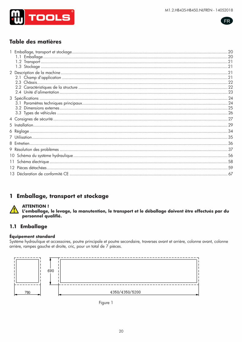
Équipement standardSystème hydraulique et accessoires, poutre principale et poutre secondaire, traverses avant et arrière, colonne avant, colonne arrière, rampes gauche et droite, cric, pour un total de 7 pièces.
Table des matières
1 Emballage, transport et stockage ............................................................................................................................201.1 Emballage ...................................................................................................................................................201.2 Transport .....................................................................................................................................................211.3 Stockage .....................................................................................................................................................21
2 Description de la machine .....................................................................................................................................212.1 Champ d’application ....................................................................................................................................212.3 Châssis ........................................................................................................................................................222.2 Caractéristiques de la structure .......................................................................................................................222.4 Unité d’alimentation ...................................................................................................................................... 23
3 Spécifications ...................................................................................................................................................... 243.1 Paramètres techniques principaux .................................................................................................................... 243.2 Dimensions externes ......................................................................................................................................253.3 Types de véhicules ........................................................................................................................................ 26
4 Consignes de sécurité ........................................................................................................................................... 275 Installation ...........................................................................................................................................................296 Réglage ..............................................................................................................................................................347 Utilisation ............................................................................................................................................................358 Entretien ..............................................................................................................................................................369 Résolution des problèmes ...................................................................................................................................... 3710 Schéma du système hydraulique ...........................................................................................................................5611 Schéma électrique ..............................................................................................................................................5812 Pièces détachées ................................................................................................................................................ 5913 Déclaration de conformité CE .............................................................................................................................. 67
UUSSEERR’’SS MMAANNUUAALL VV11..11 220011550099
- 3 -
1. Packing, transport and storage All packing, lifting, handling, transport and unpacking operations are to be performed exclusively
by expert personnel.
1.1. Packing
Standard equipment: hydraulic station and accessory, main and sub beam, front and back crossbeam, front post,
back post, left and right approaching ramp, rolling jack, total is 7 pieces.
Picture 1
1. 2. Transport:
Packing can be lifted or moved by lift trucks, cranes or bridge cranes. In case of slinging, a second person must always take care of the load, in order to avoid dangerous oscillations.
During loading and unloading operation, goods must be handled by vehicles or ships.
At the arrival of the goods, verify that all items specified in the delivery notes are included. In case of
missing parts possible defects or damage may due to transport operations.
If finding missing parts, possible defects or damage due to transport, one should examine damaged
cartons to verify the condition of damaged goods and missing parts, also the person in charge or the
carrier must be immediately informed.
The machine is heavy goods! Don’t take manpower load and unload and transporting way into consideration, the safety of working is important. Furthermore, during loading and unloading operation goods must be handled as shown in the picture. (Picture 2)
Picture 2 (Goods-lifted)
Figure 1copy
righte
d do
cume
nt - a
ll rig
hts re
serv
ed b
y FB
C
21
M1.2.HB435-HB450.NLFREN - 14052018
FR
1.2 Transport
ATTENTION !L’équipement emballé peut être soulevé et déplacé par des chariots élévateurs, des grues et des ponts roulants. En cas d’élingage, une deuxième personne doit toujours s’occuper de la charge, pour éviter des oscillations dangereuses.
Dès la livraison, vérifiez que tous les articles sont présents. Pendant le transport, des pièces peuvent être cassées, endommagées ou perdues.Si vous constatez une anomalie, inspectez les cartons endommagés et comparez leur contenu avec la liste de colisage, pour vérifier l’état des pièces. Avertissez immédiatement le transporteur ou la personne responsable.
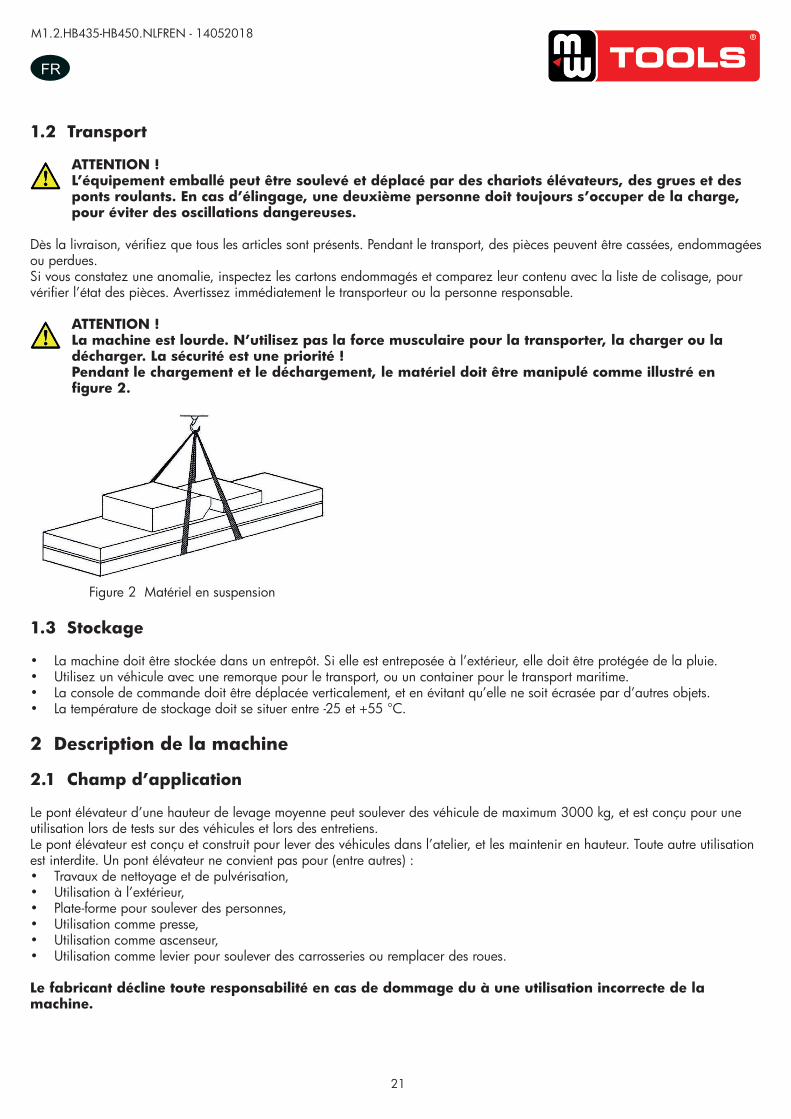
ATTENTION !La machine est lourde. N’utilisez pas la force musculaire pour la transporter, la charger ou la décharger. La sécurité est une priorité !Pendant le chargement et le déchargement, le matériel doit être manipulé comme illustré en figure 2.
Figure 2 Matériel en suspension
1.3 Stockage
• La machine doit être stockée dans un entrepôt. Si elle est entreposée à l’extérieur, elle doit être protégée de la pluie.• Utilisez un véhicule avec une remorque pour le transport, ou un container pour le transport maritime.• La console de commande doit être déplacée verticalement, et en évitant qu’elle ne soit écrasée par d’autres objets.• La température de stockage doit se situer entre -25 et +55 °C.
2 Description de la machine
2.1 Champ d’application
Le pont élévateur d’une hauteur de levage moyenne peut soulever des véhicule de maximum 3000 kg, et est conçu pour une utilisation lors de tests sur des véhicules et lors des entretiens.Le pont élévateur est conçu et construit pour lever des véhicules dans l’atelier, et les maintenir en hauteur. Toute autre utilisation est interdite. Un pont élévateur ne convient pas pour (entre autres) :• Travaux de nettoyage et de pulvérisation,• Utilisation à l’extérieur,• Plate-forme pour soulever des personnes,• Utilisation comme presse,• Utilisation comme ascenseur,• Utilisation comme levier pour soulever des carrosseries ou remplacer des roues.
Le fabricant décline toute responsabilité en cas de dommage du à une utilisation incorrecte de la machine.
UUSSEERR‟‟SS MMAANNUUAALL VV11..00 220011440088
- 4 -
1.2. Transport:
Packing can be lifted or moved by lift trucks, cranes or bridge cranes. In case of slinging, a second person must always take care of the load, in order to avoid dangerous oscillations.
During loading and unloading operation, goods must be handled by vehicles or ships.
At the arrival of the goods, verify that all items specified in the delivery notes are included. In case of
missing parts possible defects or damage may due to transport operations.
If finding missing parts, possible defects or damage due to transport, one should examine damaged
cartons according to <<Accessories Packing List>> to verify the condition of damaged goods and
missing parts, also the person in charge or the carrier must be immediately informed.
The machine is heavy goods! Don’t take manpower load and unload and transporting way into consideration, the safety of working is important. Furthermore, during loading and unloading operation goods must be handled as shown in the picture. (Picture 2)
Picture 2 (Goods-lifted)
1.3.Storage:
-The machine equipment should be stocked in the warehouse, if stocked outside should do the disposal
well of waterproof.
-Use box truck in the process of transport, use container storage when shipping.
-The control box should be placed perpendicularly during the transport; and prevent other goods from
extrusion.
-The temperature for machine storage : -25ºC-- 55ºC
2. Manual introduction This manual has been prepared for workshop personnel expert in the use of the lift operator and technicians responsible for routine maintenance fitter.
copy
righte
d do
cume
nt - a
ll rig
hts re
serv
ed b
y FB
C
22
M1.2.HB435-HB450.NLFREN - 14052018
FR
2.2 Caractéristiques de la structure
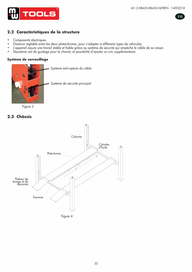
• Composants électriques.• Distance réglable entre les deux plates-formes, pour s’adapter à différents types de véhicules.• L’appareil assure une travail stable et fiable grâce au système de sécurité qui empêche le câble de se casser.• Deuxième rail de guidage pour le chariot, et possibilité d’ajouter un cric supplémentaire.
Système de verrouillage
Figure 4
Figure 3
UUSSEERR’’SS MMAANNUUAALL VV11..11 220011550099
- 5 -
3.2. Structure Features -imported electric components.
-Adjustable width between two platforms makes the lift more flexible for different vehicles.
-Device performs stable and liable work with anti-breaking rope safety insurance.
-with second lifting trolley guide rail and can add a rolling jack.
Safety lock structure
3.3. Frame
3.4. Power unit
Under the control box is hydraulic oil tank and hydraulic pump, valve and other control system. On the
control box is electrical system.
Picture 3
Insurance structure for rope fracture
Main insurance structure
Picture 4
oil cylinder
column
platform
loadingdock board
crossbeam
Système anti-rupture du câble
Système de sécurité principal
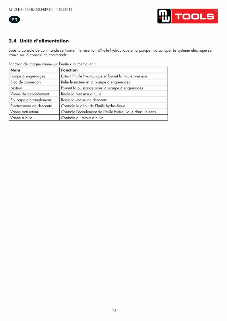
2.3 Châssis
UUSSEERR’’SS MMAANNUUAALL VV11..11 220011550099
- 5 -
3.2. Structure Features -imported electric components.
-Adjustable width between two platforms makes the lift more flexible for different vehicles.
-Device performs stable and liable work with anti-breaking rope safety insurance.
-with second lifting trolley guide rail and can add a rolling jack.
Safety lock structure
3.3. Frame
3.4. Power unit
Under the control box is hydraulic oil tank and hydraulic pump, valve and other control system. On the
control box is electrical system.
Picture 3
Insurance structure for rope fracture
Main insurance structure
Picture 4
oil cylinder
column
platform
loadingdock board
crossbeam
Plate-forme
Colonne
Cylindre d’huile
Traverse
Plateau de levage et de
descente
copy
righte
d do
cume
nt - a
ll rig
hts re
serv
ed b
y FB
C
23
M1.2.HB435-HB450.NLFREN - 14052018
FR
2.4 Unité d’alimentation
Sous la console de commande se trouvent le réservoir d’huile hydraulique et la pompe hydraulique. Le système électrique se trouve sur la console de commande.
Fonction de chaque vanne sur l’unité d’alimentation :Nom FonctionPompe à engrenages Extrait l’huile hydraulique et fournit la haute pressionBloc de connexion Relie le moteur et la pompe à engrenages Moteur Fournit la puissance pour la pompe à engrenagesVanne de débordement Règle la pression d’huileSoupape d’étranglement Règle la vitesse de descenteÉlectrovanne de descente Contrôle le débit de l’huile hydrauliqueVanne anti-retour Contrôle l’écoulement de l’huile hydraulique dans un sensVanne à bille Contrôle du retour d’huile
copy
righte
d do
cume
nt - a
ll rig
hts re
serv
ed b
y FB
C
24
M1.2.HB435-HB450.NLFREN - 14052018
FR
3 Spécifications
3.1 Paramètres techniques principaux
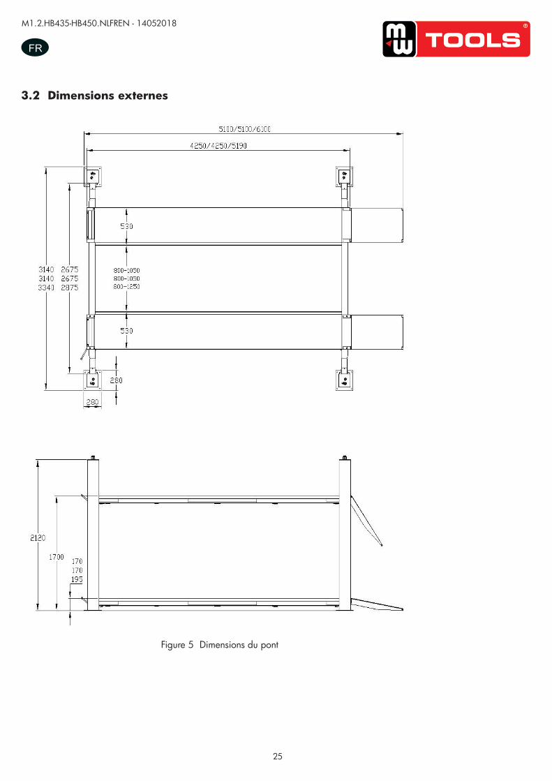
Modèle HB435 HB450Entraînement Hydraulique électriqueCapacité de levage 3500 kg 5000 KGHauteur maximale 1700 mmHauteur minimale 170 mm 195 mmLongueur plate-forme 4250 mm 5190 mmLargeur plate-forme 530 mmDurée de levage < 30 s < 35 sDurée de descente < 30 s < 35 sLargeur totale 3140 mm 3340 mmLongueur totale 5100 mm 6100 mmAlimentation électrique 3/N/PE ~ 400 V, 50 Hz, 10 AHuile hydraulique 12 l d’huile hydraulique anti-usureCapacité de levage du cric 2000 kg/3000 kgHauteur de levage du cric 520 mmLongueur de levage du cric 880 - 1370 mmDistance entre roues du cric 780 - 1200 mm
Durée de levage du cricÉlectrique RJ < 5 s
Manuel ou pneumatique RJ < 20 sDurée de descente du cric < 10 sPression RJ 6-8 kg/cm²Température de service 5 - 40 °CHumidité ambiante 30 - 95 %Niveau sonore < 76 dBAltitude ≤ 1000 m au-dessus du niveau de la merTempérature de stockage -25 ~ +55 °COption Cric rouleur
copy
righte
d do
cume
nt - a
ll rig
hts re
serv
ed b
y FB
C
25
M1.2.HB435-HB450.NLFREN - 14052018
FR
3.2 Dimensions externes
Figure 5 Dimensions du pont
UUSSEERR’’SS MMAANNUUAALL VV11..11 220011550099
- 7 -
4.2 External dimension drawing
Picture 5(lift dimension picture)
copy
righte
d do
cume
nt - a
ll rig
hts re
serv
ed b
y FB
C
26
M1.2.HB435-HB450.NLFREN - 14052018
FR
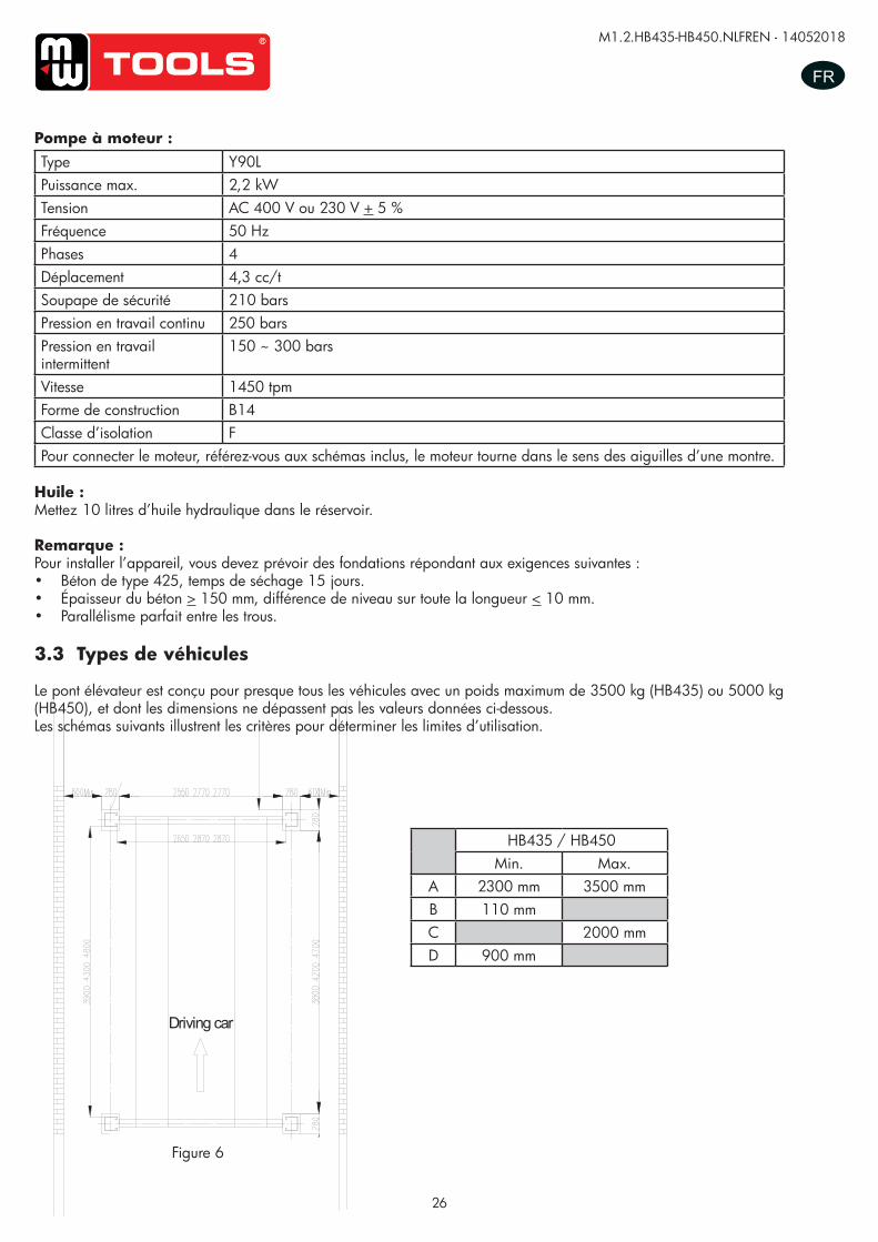
Figure 6
Pompe à moteur :Type Y90LPuissance max. 2,2 kWTension AC 400 V ou 230 V + 5 %Fréquence 50 HzPhases 4Déplacement 4,3 cc/tSoupape de sécurité 210 barsPression en travail continu 250 barsPression en travail intermittent
150 ~ 300 bars
Vitesse 1450 tpmForme de construction B14Classe d’isolation FPour connecter le moteur, référez-vous aux schémas inclus, le moteur tourne dans le sens des aiguilles d’une montre.
Huile :Mettez 10 litres d’huile hydraulique dans le réservoir.
Remarque :Pour installer l’appareil, vous devez prévoir des fondations répondant aux exigences suivantes :• Béton de type 425, temps de séchage 15 jours.• Épaisseur du béton > 150 mm, différence de niveau sur toute la longueur < 10 mm.• Parallélisme parfait entre les trous.
3.3 Types de véhicules
Le pont élévateur est conçu pour presque tous les véhicules avec un poids maximum de 3500 kg (HB435) ou 5000 kg (HB450), et dont les dimensions ne dépassent pas les valeurs données ci-dessous.Les schémas suivants illustrent les critères pour déterminer les limites d’utilisation.
HB435 / HB450Min. Max.
A 2300 mm 3500 mmB 110 mmC 2000 mmD 900 mm
UUSSEERR’’SS MMAANNUUAALL VV11..11 220011550099
- 9 -
Driving car
The thickness and leveling of the base concrete are essential and the leveling adjustment ability of the machine itself cannot be relied upon to excessively. Types of vehicle suitable for being lifted and overall dimensions.
4.3. Types of vehicles suitable for
Lift are suitable for virtually all vehicles with total weight of no more than 3500kg/4000kg/5000kg and with
dimensions not exceeding the below data.
The following diagrams illustrate criteria used to define the operating limits of the lift.
Caution: The lower parts of the vehicle underbody could interfere with structural parts of the lift, take particular parts of the sports car.
The lift will also handle customized or non-standard vehicles, provided they are within the maximum specified
carrying capacity.
Also the personnel safety zone must be defined in relation to vehicle with unusual dimensions.
3.5T/4T/5T
Min.(mm) Max.(mm)
A 2300 3500/3500/4500
B 110
C 2000
D 900
Picture 6
copy
righte
d do
cume
nt - a
ll rig
hts re
serv
ed b
y FB
C
27
M1.2.HB435-HB450.NLFREN - 14052018
FR
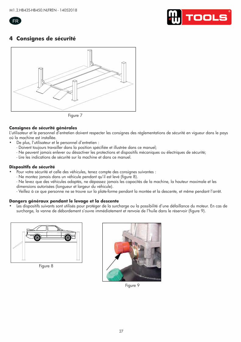
4 Consignes de sécurité
Consignes de sécurité généralesL’utilisateur et le personnel d’entretien doivent respecter les consignes des réglementations de sécurité en vigueur dans le pays où la machine est installée.• De plus, l’utilisateur et le personnel d’entretien :
- Doivent toujours travailler dans la position spécifiée et illustrée dans ce manuel; - Ne peuvent jamais enlever ou désactiver les protections et dispositifs mécaniques ou électriques de sécurité; - Lire les indications de sécurité sur la machine et dans ce manuel.
Dispositifs de sécurité• Pour votre sécurité et celle des véhicules, tenez compte des consignes suivantes :
- Ne montez jamais dans un véhicule pendant qu’il est levé (figure 8). - Ne levez que des véhicules adaptés, ne dépassez jamais les capacités de la machine, la hauteur maximale et les dimensions autorisées (longueur et largeur du véhicule). - Veillez à ce que personne ne se trouve sur la plate-forme pendant la montée et la descente, et même pendant l’arrêt.
Dangers généraux pendant le levage et la descente• Les dispositifs suivants sont utilisés pour protéger de la surcharge ou la possibilité d’une défaillance du moteur. En cas de
surcharge, la vanne de débordement s’ouvre immédiatement et renvoie de l’huile dans le réservoir (figure 9).
Figure 8
UUSSEERR’’SS MMAANNUUAALL VV11..11 220011550099
- 11 -
General precautions The operator and the maintenance fitter are required to observe the prescriptions of safety regulation in
force in the country of installation of the lift.
Furthermore, the operator and maintenance fitter must:
-Always work in the stations specified and illustrated in this manual;
-Never remove or deactivate the guards and mechanical, electrical, or other types of safety devices;
-Read the safety notices placed on the machine and the safety information in this manual.
In the manual all safety notices are shown as follows: Warning: indicates following operations that are unsafe and can cause minor injury to persons and
damage the lift, the vehicle or other property.
Risk and protection devices
For optimal personal safety and safety of vehicles, observe the following regulations:
-Do not enter the safety and safety of vehicles is being lifted. (Picture 8)
-Be sure to lift only approved vehicles, never exceed the specified carrying capacity, maximum height,
and projection (vehicle length and width);
-Make sure that there is no person on the platforms during up and down movements and during
standing.(Picture 8)
General risks for lifting or descent The following safety equipments are used to protect over loading or the possibility of engine failure.
In the condition of over loading, the over-falling valve will open and directly return oil to the oil tank.
(Picture 9)
Picture 8
Picture 9
UUSSEERR’’SS MMAANNUUAALL VV11..11 220011550099
- 11 -
General precautions The operator and the maintenance fitter are required to observe the prescriptions of safety regulation in
force in the country of installation of the lift.
Furthermore, the operator and maintenance fitter must:
-Always work in the stations specified and illustrated in this manual;
-Never remove or deactivate the guards and mechanical, electrical, or other types of safety devices;
-Read the safety notices placed on the machine and the safety information in this manual.
In the manual all safety notices are shown as follows: Warning: indicates following operations that are unsafe and can cause minor injury to persons and
damage the lift, the vehicle or other property.
Risk and protection devices
For optimal personal safety and safety of vehicles, observe the following regulations:
-Do not enter the safety and safety of vehicles is being lifted. (Picture 8)
-Be sure to lift only approved vehicles, never exceed the specified carrying capacity, maximum height,
and projection (vehicle length and width);
-Make sure that there is no person on the platforms during up and down movements and during
standing.(Picture 8)
General risks for lifting or descent The following safety equipments are used to protect over loading or the possibility of engine failure.
In the condition of over loading, the over-falling valve will open and directly return oil to the oil tank.
(Picture 9)
Picture 8
Picture 9 Figure 9
Figure 7
UUSSEERR’’SS MMAANNUUAALL VV11..11 220011550099
- 10 -
Read this chapter carefully and completely since important information for the safety of the operator or others in case of improper use of the lift is included.
In the following text there are clear explanations regarding certain situations of risk or danger that may
arise during the operation or maintenance of the lift, the safety device installed and the correct use of
such systems, residual risks and operative procedures to use (general specific precautions to eliminate
potential hazards).
Lifts are designed and built to lift vehicles and hold them in the elevated position in an enclosed workshop. All other uses of the lifts are unauthorized. In particular, the lifts are not suitable for: -Washing spray work; -Use in outdoors; -Creating raised platforms for personnel or lifting personnel; -Use as a press for crushing purposes; -Use as elevator; -Use as a lift jack for lifting vehicle bodies or changing wheels.
The manufacturer is not liable for any injury to persons or damage to vehicles and other property caused
by the incorrect and unauthorized use of the lifts.
During lifting and descent, the operator must remain in the control station as the diagrams illustrated.
As the diagrams illustrated, the presence of persons inside the danger zone indicated is strictly
prohibited. During operations persons are admitted to the area beneath the vehicle only when the vehicle
is already in the elevated position, when the platforms are stationary, and when the mechanical safety
devices are firmly engaged (e.g.: the safety gear is completely locked).
Do not use the lift without protection devices or with the protection devices inhibited.
Failure to comply with this regulation can cause serious injury to persons, and irreparable damage to the
lift and the vehicle being lifted.
5. Safety
Picture 7
copy
righte
d do
cume
nt - a
ll rig
hts re
serv
ed b
y FB
C
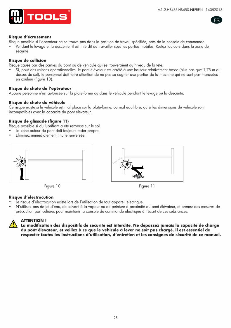
28
M1.2.HB435-HB450.NLFREN - 14052018
FR
Risque d’électrocution• Le risque d’électrocution existe lors de l’utilisation de tout appareil électrique.• N’utilisez pas de jet d’eau, de solvant à la vapeur ou de peinture à proximité du pont élévateur, et prenez des mesures de
précaution particulières pour maintenir la console de commande électrique à l’écart de ces substances.
ATTENTION !La modification des dispositifs de sécurité est interdite. Ne dépassez jamais la capacité de charge du pont élévateur, et veillez à ce que le véhicule à lever ne soit pas chargé. Il est essentiel de respecter toutes les instructions d’utilisation, d’entretien et les consignes de sécurité de ce manuel.
Risque d’écrasementRisque possible si l’opérateur ne se trouve pas dans la position de travail spécifiée, près de la console de commande.• Pendant le levage et la descente, il est interdit de travailler sous les parties mobiles. Restez toujours dans la zone de
sécurité.
Risque de collisionRisque causé par des parties du pont ou de véhicule qui se trouveraient au niveau de la tête.• Si, pour des raisons opérationnelles, le pont élévateur est arrêté à une hauteur relativement basse (plus bas que 1,75 m au-
dessus du sol), le personnel doit faire attention de ne pas se cogner aux parties de la machine qui ne sont pas marquées en couleur (figure 10).
Risque de chute de l’opérateurAucune personne n’est autorisée sur la plate-forme ou dans le véhicule pendant le levage ou la descente.
Risque de chute du véhiculeCe risque existe si le véhicule est mal placé sur la plate-forme, ou mal équilibré, ou si les dimensions du véhicule sont incompatibles avec la capacité du pont élévateur.
Risque de glissade (figure 11)Risque possible si du lubrifiant a été renversé sur le sol.• La zone autour du pont doit toujours rester propre. • Éliminez immédiatement l’huile renversée.
Figure 10 Figure 11
UUSSEERR’’SS MMAANNUUAALL VV11..11 220011550099
- 12 -
Risk of crushing Possible if the operator controlling the lift is not I the specified position at the control panel.
When the platforms (and vehicle) are lowering the operator must never be partly or completely underneath the
movable structure. Always remain in the control zone.
Risk of impact (Picture 10) Caused by the parts of the lift or the vehicle that is positioned at head height.
When, due to operational reasons, the lift is stopped at relatively low elevations personnel must be careful to avoid
impact with parts of the machine not marked with special color.
Risk of operator falling No person is permitted in the platform or in the vehicle when the lift lifting and lowing,
Risk of vehicle falling from lift This hazard may cause of incorrect positioning of the vehicle on the platforms, incorrect stopping of the vehicle, or
vehicles of dimensions that are not compatible with the capacity of the lift.
Never attempt to perform test by driving the vehicle while it is on the platforms Never leave objects in the lowering area of the movable parts of the lift.
Risk of slipping(Picture 11) Caused by lubricant contamination of the floor around the lift.
The area beneath and immediately surrounding the lift and also the platforms must be kept clean.
Remove any oil spills immediately.
Picture 10
Picture 11
copy
righte
d do
cume
nt - a
ll rig
hts re
serv
ed b
y FB
C
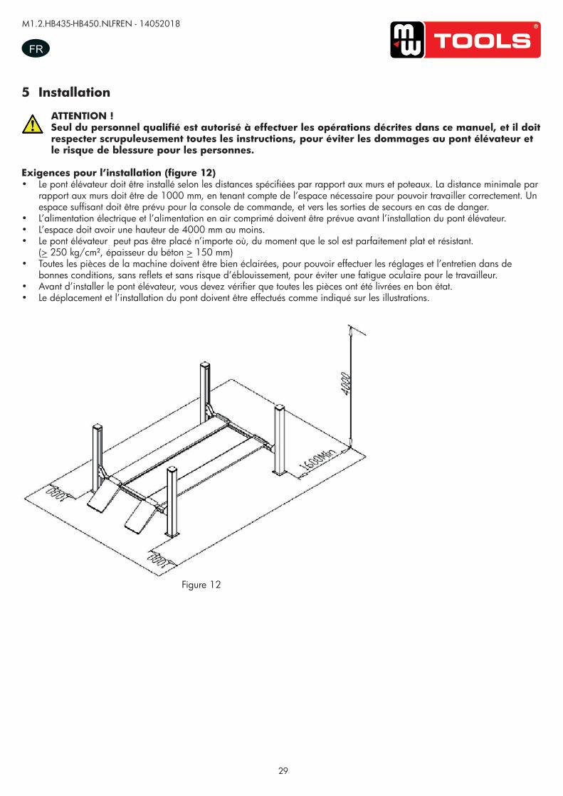
29
M1.2.HB435-HB450.NLFREN - 14052018
FR
5 Installation
ATTENTION !Seul du personnel qualifié est autorisé à effectuer les opérations décrites dans ce manuel, et il doit respecter scrupuleusement toutes les instructions, pour éviter les dommages au pont élévateur et le risque de blessure pour les personnes.
Exigences pour l’installation (figure 12)• Le pont élévateur doit être installé selon les distances spécifiées par rapport aux murs et poteaux. La distance minimale par
rapport aux murs doit être de 1000 mm, en tenant compte de l’espace nécessaire pour pouvoir travailler correctement. Un espace suffisant doit être prévu pour la console de commande, et vers les sorties de secours en cas de danger.
• L’alimentation électrique et l’alimentation en air comprimé doivent être prévue avant l’installation du pont élévateur.• L’espace doit avoir une hauteur de 4000 mm au moins.• Le pont élévateur peut pas être placé n’importe où, du moment que le sol est parfaitement plat et résistant.
(> 250 kg/cm², épaisseur du béton > 150 mm)• Toutes les pièces de la machine doivent être bien éclairées, pour pouvoir effectuer les réglages et l’entretien dans de
bonnes conditions, sans reflets et sans risque d’éblouissement, pour éviter une fatigue oculaire pour le travailleur.• Avant d’installer le pont élévateur, vous devez vérifier que toutes les pièces ont été livrées en bon état.• Le déplacement et l’installation du pont doivent être effectués comme indiqué sur les illustrations.
Figure 12
UUSSEERR’’SS MMAANNUUAALL VV11..11 220011550099
- 13 -
Risk of electric shock Risk of electric shock in areas of the lift housing electrical wiring.
Do not use jets of water, steam solvents or paint next to the lift, and take special care to keep such substances
clear of the electrical control panel.
The handling of safety devices is strictly forbidden. Never exceed the maximum carrying capacity of the lift, make sure the vehicles to be lifted have no load. It is therefore essential to adhere scrupulously to all regulations regarding use, maintenance and safety contained in this manual.
6. Installation
Skilled and authorized personnel only should be allowed to perform these operations, follow all instructions shown below carefully, in order to prevent possible damage to the car lift or risk of injury to people.
Installation requirements (Picture 12) The car lift must be installed according to the specified safety distances from walls must be 1000 mm at least,
taking into consideration of the necessary space to work easily. Further space for the control site and for possible
runways in case of emergency is also necessary; the room must be previously arranged for the power supply and
pneumatic feed of the car lift. The room must be 4000 mm in height, at least, the car lift can be placed on any floor,
as long as it is perfectly level and sufficiently resistant.(≥250kg/cm2)
-All parts of the machine must be uniformly lit with sufficient light to make sure that the adjustment and
maintenance operations specified in the manual can be performed safely, and without areas of shadow, reflected
light, glare and avoiding all situations that could give rise to eye fatigue.
-The lighting must be installed in accordance with the laws in force in the place of installation.
-the thickness and leveling of the base concrete are essential
-thickness of concrete≥150mm, the leveling of whole length≤10mm.
Picture 12
copy
righte
d do
cume
nt - a
ll rig
hts re
serv
ed b
y FB
C
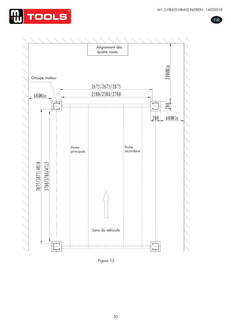
30
M1.2.HB435-HB450.NLFREN - 14052018
FRUUSSEERR’’SS MMAANNUUAALL VV11..11 220011550099
- 14 -
Installation scheme for four post lift
Picture 13
Groupe moteur
Poutre secondaire
Sens du véhicule
Alignement des quatre roues
Poutre principale
Figure 13
copy
righte
d do
cume
nt - a
ll rig
hts re
serv
ed b
y FB
C

31
M1.2.HB435-HB450.NLFREN - 14052018
FR
Figure 14
Installation des traverses• Fixez la poutre avant et la poutre arrière sur le sol.• Placez une pièce ce bois et de métal sous les poutres, pour les surélever de 100 - 300 mm.• Fixez les 8 pièces anti-collision à l’intérieur et à l’extérieur des traverses.
Installation des plates-formes• Placez les plates-formes sur les traverses. La plate-forme principale doit être placée à gauche par rapport au sens du
véhicule, la plate-forme secondaire à droite. La rainure pour la roue doit se trouver du côté intérieur.• Vérifiez que les traverses et les plates-formes sont bien parallèles. Placez ensuite les quatre colonnes sur le côté des
traverses, et fixez les écrous dans le haut de la colonne avec le câble en acier. Faites passer l’ergot de sécurité à travers l’axe d’arrêt, et fixez l’écrou dans le haut de la colonne.
Connexion des câbles en acier• Desserrez les écrous du câble en acier, en évitant que les câbles ne s’enroulent les uns avec les autres.• Le câble court s’insère dans la rainure de la poulie de gauche. Desserrez l’axe de la poulie dans la traverse.
Installez l’axe de la poulie après avoir mis le câble.
UUSSEERR’’SS MMAANNUUAALL VV11..11 220011550099
- 15 -
Crossbeam installation -fix the front and back crossbeam on the floor.
-Put a wood or an iron under the crossbeam in order to raise 100-300mm.
-fix eight nylon anti-crashes inner and outer of the crossbeam.
Platform installation: -Put two platforms on the transom, the main platform should located on the left side of the moving vehicle direction,
the sub-platform located on the right side, the rolling wheel notch on the platform should inside.
-check two platforms and the diagonal of two transom are straight, then put four posts on the side of the transom,
and fix the nuts on the roof of the post with steel cable, put the safety teeth trough the limit axis, also fix the nuts on
the roof of the post.
Steel cable connection: -Unload the nuts of the steel cable, avoid the steel cables being twining with each other.
- The short steel cable goes through the groove of pulley on the left side. Loose the shaft of pulley inside the
crossbeam. Install the shaft of pulley after finishing putting on the steel cable.
Post installation: -Unload the screws under the insurance in the post.
-stick the column on the nylon block of the crossbeam, insert the insurance strip into the groove of crossbeam
-measuring the column and use the thick iron mat to make the column base plate vertical with the column.
Rolling jack installation(optional part):
-adjust the distance of the rolling jack; put the rolling jack between the slide track.
-adjust the sub beam to make sure the sliding of the rolling jack.
Picture 14
Installation des colonnes• Desserrez les vis sous la sécurité dans la colonne.• Placez la colonne sur le bloc de nylon de la traverse, insérez la bande de sécurité dans la rainure de la traverse.• Mesurez la colonne et utilisez une équerre pour placer la base de la colonne verticalement avec la colonne.
Installation du cric (option)• Réglez la distance du cric. Placez le cric entre les glissières.• Réglez la poutre secondaire pour que le cric coulisse bien.
copy
righte
d do
cume
nt - a
ll rig
hts re
serv
ed b
y FB
C
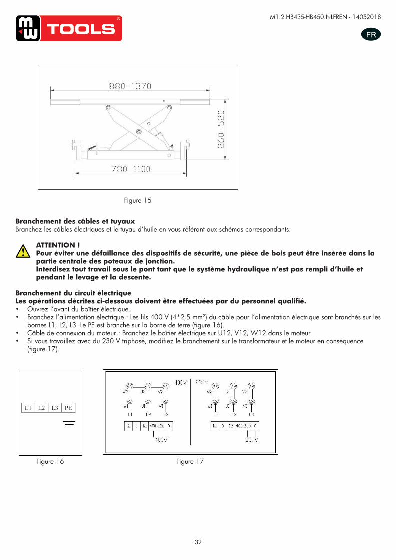
32
M1.2.HB435-HB450.NLFREN - 14052018
FR
Branchement des câbles et tuyauxBranchez les câbles électriques et le tuyau d’huile en vous référant aux schémas correspondants.
ATTENTION !Pour éviter une défaillance des dispositifs de sécurité, une pièce de bois peut être insérée dans la partie centrale des poteaux de jonction.Interdisez tout travail sous le pont tant que le système hydraulique n’est pas rempli d’huile et pendant le levage et la descente.
Branchement du circuit électriqueLes opérations décrites ci-dessous doivent être effectuées par du personnel qualifié.• Ouvrez l’avant du boîtier électrique.• Branchez l’alimentation électrique : Les fils 400 V (4*2,5 mm²) du câble pour l’alimentation électrique sont branchés sur les
bornes L1, L2, L3. Le PE est branché sur la borne de terre (figure 16).• Câble de connexion du moteur : Branchez le boîtier électrique sur U12, V12, W12 dans le moteur.• Si vous travaillez avec du 230 V triphasé, modifiez le branchement sur le transformateur et le moteur en conséquence
(figure 17).
UUSSEERR’’SS MMAANNUUAALL VV11..11 220011550099
- 16 -
Line connection Connect the electrical and oil line according to the electric wiring diagram and oil line connection
To avoid the unexpected lift closure due to mechanical safety device release insert wooden pieces in the inner part of the base frame. Pay attention not to work under the lift until the hydraulic system has not been completely filled with hydraulic oil.
Electrical circuit connection:
According to the electric connection.
Skilled personnel only are allowed to perform the operations shown below.
-open the control box front cover
-connection of power supply: the 400 three-phase five-wires (4*2.5mm2) for power supply are connected to
terminals 1#, 2#, 3#.The PE is connected to the ground wire.(Picture 16)
-Electric motor wire connection: connect the control box with U12﹟、V12#、W12# electric wire to motor wire box.
-therefore if you wish the lift to operate at 230V three-phase, change the connection on the transformer and motor.
(Picture 17)
.
L1 L2 L3 PE
Picture 15
Picture 16 Picture 17
Figure 15
Figure 16 Figure 17
copy
righte
d do
cume
nt - a
ll rig
hts re
serv
ed b
y FB
C
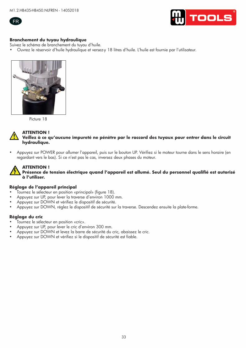
33
M1.2.HB435-HB450.NLFREN - 14052018
FR
Branchement du tuyau hydrauliqueSuivez le schéma de branchement du tuyau d’huile.• Ouvrez le réservoir d’huile hydraulique et versez-y 18 litres d’huile. L’huile est fournie par l’utilisateur.
UUSSEERR’’SS MMAANNUUAALL VV11..11 220011550099
- 17 -
Hydraulic hoses connection:
Follow <<oil hose connection diagram >> to connect the hydraulic oil hoses
Open the hydraulic oil tank, add 18L of hydraulic oil into the oil tank, the hydraulic oil is provided by the user.
Make sure the clean of hydraulic oil, prevent any impurity into the oil line, lead the digest of the oil line and no working of the solenoid valve. -press the “power” button to turn on power, clicking the “up” button, check whether the motor turns clockwise
(looking downward), if not press “power” button, change the phase of the motor.
When turn on power, there is high voltage in the control box, only authorized person can operate.
Main machine adjustment -Turn the selector switch to the “main” position. (Picture18)
-press “up” button SB1, lift crossbeam approximately 1000mm.
-press “down” button SB2, verity the safety instruction.
-press “down” button SB2, adjust the safety instruction on the frame of the crossbeam. Then lower the platform.
Rolling jack adjustment -turn the selector switch to “rolling jack” position.
-press “up” button SB1, lift approximately 300mm.
-press “down” button SB2 and lift the safety rod of rolling jack, lower the rolling jack.
-press “down” button SB2, verify the safety instruction is reliable.
Picture 18 Picture 18
ATTENTION !Veillez à ce qu’aucune impureté ne pénètre par le raccord des tuyaux pour entrer dans le circuit hydraulique.
• Appuyez sur POWER pour allumer l’appareil, puis sur le bouton UP. Vérifiez si le moteur tourne dans le sens horaire (en regardant vers le bas). Si ce n’est pas le cas, inversez deux phases du moteur.
ATTENTION !Présence de tension électrique quand l’appareil est allumé. Seul du personnel qualifié est autorisé à l’utiliser.
Réglage de l’appareil principal• Tournez le sélecteur en position «principal» (figure 18).• Appuyez sur UP, pour lever la traverse d’environ 1000 mm.• Appuyez sur DOWN et vérifiez le dispositif de sécurité.• Appuyez sur DOWN, réglez le dispositif de sécurité sur la traverse. Descendez ensuite la plate-forme.
Réglage du cric• Tournez le sélecteur en position «cric».• Appuyez sur UP, pour lever le cric d’environ 300 mm.• Appuyez sur DOWN et levez la barre de sécurité du cric, abaissez le cric.• Appuyez sur DOWN et vérifiez si le dispositif de sécurité est fiable.
copy
righte
d do
cume
nt - a
ll rig
hts re
serv
ed b
y FB
C
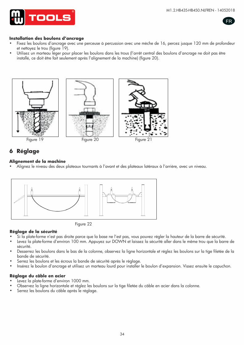
34
M1.2.HB435-HB450.NLFREN - 14052018
FR
UUSSEERR‟‟SS MMAANNUUAALL VV11..00 220011440088
- 15 -
Platform Installation:
-Place two lift platforms on the position of the location
-The bottom of oil cylinder is located in the frontage of machine (the direction of getting on the vehicle)
-Use fork car or other lifting equipments to lift the platform (Picture17) and make sure that the safety
equipment of machine is both turned on and locked.
Picture 17
To avoid failure of machine safety equipment, can insert a wood in the middle part of joint-pole. Prohibit working beneath the lift when hydraulic system is not completely equipped with hydraulic oil and take the action of up and down operations. -When moving the lift platform, adjust the space between two platforms; make sure that the two platforms are parallel.
Ground bolts installation
The ground bolts installation must start after the expiry date on the maintenance of concert, otherwise, it
will affect the quality of solidity.
-Adjust the parallel of the platform and the distance of two platform as Picture 18 requires.
-Fix the anchor bolts with a percussion electric drill (percussion drill bit is of 16), drill to 120mm hole and
clean the hole.(Picture 18) -Use light hammer to install the ground bolts into the hole (need not install the central expanded nail of
ground bolts, install it after level adjustment.) (Picture 19)
Picture 18 Picture 19 Picture 20
Installation des boulons d’ancrage• Fixez les boulons d’ancrage avec une perceuse à percussion avec une mèche de 16, percez jusque 120 mm de profondeur
et nettoyez le trou (figure 19).• Utilisez un marteau léger pour placer les boulons dans les trous (l’arrêt central des boulons d’ancrage ne doit pas être
installé, ce doit être fait seulement après l’alignement de la machine) (figure 20).
Figure 19 Figure 20 Figure 21
6 Réglage
Alignement de la machine• Alignez le niveau des deux plateaux tournants à l’avant et des plateaux latéraux à l’arrière, avec un niveau.
Figure 22
Réglage de la sécurité• Si la plate-forme n’est pas droite parce que la base ne l’est pas, vous pouvez régler la hauteur de la barre de sécurité.• Levez la plate-forme d’environ 100 mm. Appuyez sur DOWN et laissez la sécurité aller dans le même trou que la barre de
sécurité.• Desserrez les boulons dans le bas de la colonne, observez la ligne horizontale et réglez les boulons sur la tige filetée de la
bande de sécurité.• Serrez les boulons et les écrous la bande de sécurité après le réglage.• Insérez le boulon d’ancrage et utilisez un marteau lourd pour installer le boulon d’expansion. Vissez ensuite le capuchon.
Réglage du câble en acier• Levez la plate-forme d’environ 1000 mm.• Observez la ligne horizontale et réglez les boulons sur la tige filetée du câble en acier dans la colonne.• Serrez les boulons du câble après le réglage.
UUSSEERR’’SS MMAANNUUAALL VV11..11 220011550099
- 18 -
Anchor bolts installation -Fix the anchor bolts with a percussion electric drill (percussion drill bit is of 16), drill to 120mm hole and
clean the hole.(Picture 20) -Use light hammer to install the ground bolts into the hole (need not install the central expanded nail of
ground bolts, install it after level adjustment.) (Picture 21)
7. Adjustment
Level adjustment (Picture 23)
-adjust the level of the two front turntable and the slide plates on both sides at back with a leveling instrument.
Insurance level adjustment.
-if the unparallel of the basement lead to the unparallel of the platform, can adjust the height of the safety rod.
-lift the platform approximately 100mm; press “down” button let the insurance go into the same hole of insurance
rod.
-loose the bolts on the bottom of column, observe the horizontal line and adjust the bolts on the insurance strip
thread rod
-fix the insurance strip bolts and nuts after level adjustment.
-insert the anchor, use a heavy hammer to install the expansion bolts and screw down the screw cap
Steel cable adjustment
-lift the platform approximately 1000mm.
-observe the horizontal line and adjust the bolts on the steel cable thread rod inside the column.
-fix the steel cable bolts after level adjustment.
Picture 20 Picture 21
Picture 23
Picture 22
copy
righte
d do
cume
nt - a
ll rig
hts re
serv
ed b
y FB
C
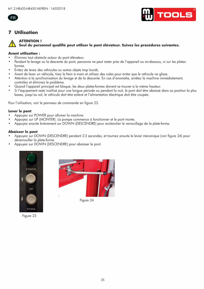
35
M1.2.HB435-HB450.NLFREN - 14052018
FR
7 Utilisation
ATTENTION !Seul du personnel qualifié peut utiliser le pont élévateur. Suivez les procédures suivantes.
Avant utilisation :• Éliminez tout obstacle autour du pont élévateur.• Pendant le levage ou la descente du pont, personne ne peut rester près de l’appareil ou en-dessous, ni sur les plates-
formes.• Évitez de levez des véhicules ou autres objets trop lourds.• Avant de lever un véhicule, tirez le frein à main et utilisez des cales pour éviter que le véhicule ne glisse.• Attention à la synchronisation du levage et de la descente. En cas d’anomalie, arrêtez la machine immédiatement,
contrôlez et éliminez le problème.• Quand l’appareil principal est bloqué, les deux plates-formes doivent se trouver à la même hauteur.• Si l’équipement reste inutilisé pour une longue période ou pendant la nuit, le pont doit être abaissé dans sa position la plus
basse, jusqu’au sol, le véhicule doit être enlevé et l’alimentation électrique doit être coupée.
Pour l’utilisation, voir le panneau de commande en figure 23.
Lever le pont• Appuyez sur POWER pour allumer la machine.• Appuyez sur UP (MONTER). La pompe commence à fonctionner et le pont monte. • Appuyez ensuite brièvement sur DOWN (DESCENDRE) pour enclencher le verrouillage de la plate-forme.
Abaisser le pont• Appuyez sur DOWN (DESCENDRE) pendant 2-3 secondes, et tournez ensuite le levier mécanique (voir figure 24) pour
déverrouiller la plate-forme. • Appuyez sur DOWN (DESCENDRE) pour abaisser le pont.
Figure 23
Figure 24
copy
righte
d do
cume
nt - a
ll rig
hts re
serv
ed b
y FB
C
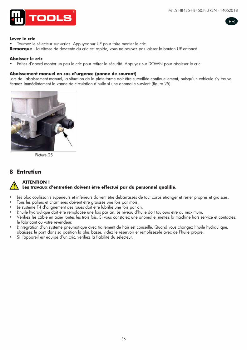
36
M1.2.HB435-HB450.NLFREN - 14052018
FR
Lever le cric• Tournez le sélecteur sur «cric». Appuyez sur UP pour faire monter le cric.Remarque : La vitesse de descente du cric est rapide, vous ne pouvez pas laisser le bouton UP enfoncé.
Abaisser le cric• Faites d’abord monter un peu le cric pour retirer la sécurité. Appuyez sur DOWN pour abaisser le cric.
Abaissement manuel en cas d’urgence (panne de courant)Lors de l’abaissement manuel, la situation de la plate-forme doit être surveillée continuellement, puisqu’un véhicule s’y trouve. Fermez immédiatement la vanne de circulation d’huile si une anomalie survient (figure 25).
UUSSEERR’’SS MMAANNUUAALL VV11..11 220011550099
- 20 -
Only authorized person can operate, doing alignment only after “locking” process.
Ordinary rolling jack lifting -turn the selector switch on “rolling jack” position, clicking “up” button, rolling jack is lift.
Note: the speed of rolling jack is fast, cannot press “up” button continuously.
Ordinary rolling jack lowering -First lift the rolling jack a little, lift up the insurance of rolling jack, press the “down” button to lower the lift
Emergency manual operation for lowering (power failure) When lowering through manual operation, should observe the condition of platform at any time because
there are vehicles on the platform. If there is something abnormal, screw down oil loop valve
immediately.(refer to Picture 26)
The process of manual operation
9.Maintenance and care The maintenance and care of the lift must be operated by skilled person.
-the upper and lower sliding blocks must be cleared of foreign objects, and must be kept clean and lubricated. -all bearings and hinges on this machine must be lubricated once a month
-the type of F4 of the four-wheel alignment should lubricate yearly.
-the hydraulic oil must be replaced one time each year. The oil level should always be kept at upper limit position.
-check the steel line every three times and if there is something wrong, stop using, and tell the manufacture.
-the integration of the pneumatic system with an air treatment unit is suggested.
When change hydraulic oil, put machines to the lowest position, have the oil tank empty, when add new oil, should
have the oil cleaned.
-if equipped with rolling jack, check the liability of the switch.
Picture 26 Picture 25
8 Entretien
ATTENTION !Les travaux d’entretien doivent être effectué par du personnel qualifié.
• Les bloc coulissants supérieurs et inférieurs doivent être débarrassés de tout corps étranger et rester propres et graissés.• Tous les paliers et charnières doivent être graissés une fois par mois.• Le système F4 d’alignement des roues doit être lubrifié une fois par an.• L’huile hydraulique doit être remplacée une fois par an. Le niveau d’huile doit toujours être au maximum.• Vérifiez les câble en acier toutes les trois fois. Si vous constatez une anomalie, mettez la machine hors service et contactez
le fabricant ou votre revendeur.• L’intégration d’un système pneumatique avec traitement de l’air est conseillé. Quand vous changez l’huile hydraulique,
abaissez le pont dans sa position la plus basse, videz le réservoir et remplissez-le avec de l’huile propre.• Si l’appareil est équipé d’un cric, vérifiez la fiabilité du sélecteur.
copy
righte
d do
cume
nt - a
ll rig
hts re
serv
ed b
y FB
C
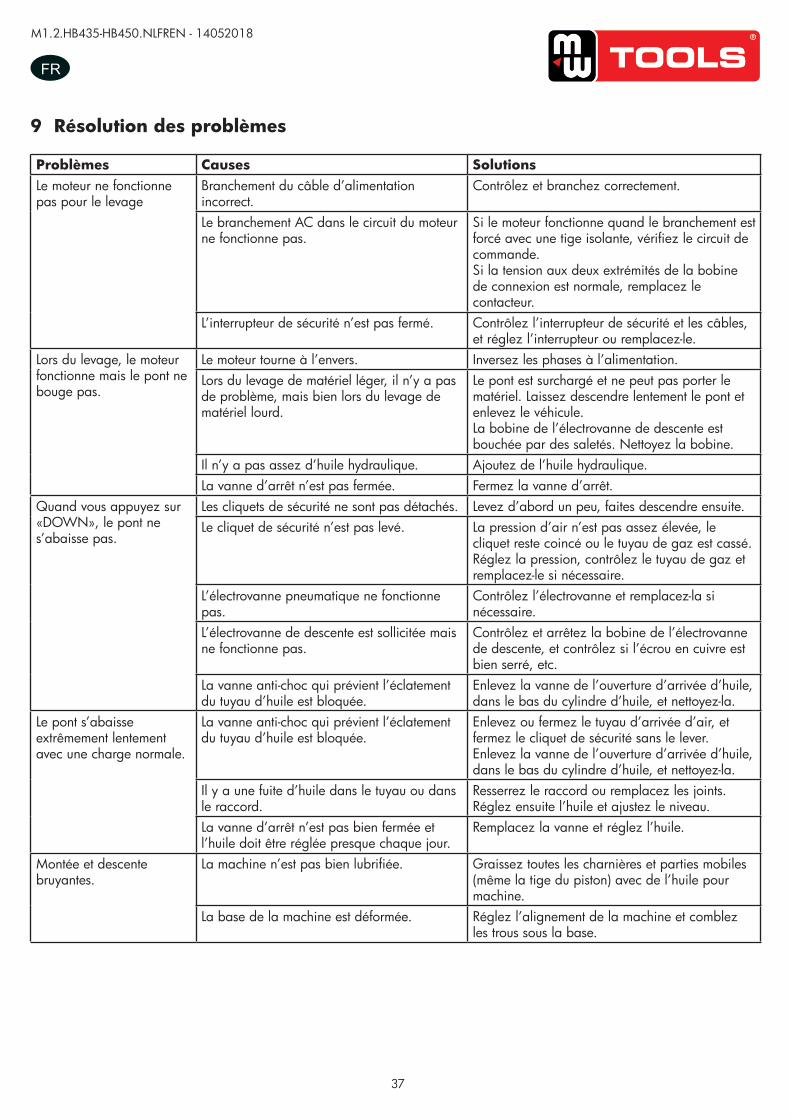
37
M1.2.HB435-HB450.NLFREN - 14052018
FR
9 Résolution des problèmes
Problèmes Causes SolutionsLe moteur ne fonctionne pas pour le levage
Branchement du câble d’alimentation incorrect.
Contrôlez et branchez correctement.
Le branchement AC dans le circuit du moteur ne fonctionne pas.
Si le moteur fonctionne quand le branchement est forcé avec une tige isolante, vérifiez le circuit de commande.Si la tension aux deux extrémités de la bobine de connexion est normale, remplacez le contacteur.
L’interrupteur de sécurité n’est pas fermé. Contrôlez l’interrupteur de sécurité et les câbles, et réglez l’interrupteur ou remplacez-le.
Lors du levage, le moteur fonctionne mais le pont ne bouge pas.
Le moteur tourne à l’envers. Inversez les phases à l’alimentation.Lors du levage de matériel léger, il n’y a pas de problème, mais bien lors du levage de matériel lourd.
Le pont est surchargé et ne peut pas porter le matériel. Laissez descendre lentement le pont et enlevez le véhicule.La bobine de l’électrovanne de descente est bouchée par des saletés. Nettoyez la bobine.
Il n’y a pas assez d’huile hydraulique. Ajoutez de l’huile hydraulique.La vanne d’arrêt n’est pas fermée. Fermez la vanne d’arrêt.
Quand vous appuyez sur «DOWN», le pont ne s’abaisse pas.
Les cliquets de sécurité ne sont pas détachés. Levez d’abord un peu, faites descendre ensuite.Le cliquet de sécurité n’est pas levé. La pression d’air n’est pas assez élevée, le
cliquet reste coincé ou le tuyau de gaz est cassé. Réglez la pression, contrôlez le tuyau de gaz et remplacez-le si nécessaire.
L’électrovanne pneumatique ne fonctionne pas.
Contrôlez l’électrovanne et remplacez-la si nécessaire.
L’électrovanne de descente est sollicitée mais ne fonctionne pas.
Contrôlez et arrêtez la bobine de l’électrovanne de descente, et contrôlez si l’écrou en cuivre est bien serré, etc.
La vanne anti-choc qui prévient l’éclatement du tuyau d’huile est bloquée.
Enlevez la vanne de l’ouverture d’arrivée d’huile, dans le bas du cylindre d’huile, et nettoyez-la.
Le pont s’abaisse extrêmement lentement avec une charge normale.
La vanne anti-choc qui prévient l’éclatement du tuyau d’huile est bloquée.
Enlevez ou fermez le tuyau d’arrivée d’air, et fermez le cliquet de sécurité sans le lever.Enlevez la vanne de l’ouverture d’arrivée d’huile, dans le bas du cylindre d’huile, et nettoyez-la.
Il y a une fuite d’huile dans le tuyau ou dans le raccord.
Resserrez le raccord ou remplacez les joints. Réglez ensuite l’huile et ajustez le niveau.
La vanne d’arrêt n’est pas bien fermée et l’huile doit être réglée presque chaque jour.
Remplacez la vanne et réglez l’huile.
Montée et descente bruyantes.
La machine n’est pas bien lubrifiée. Graissez toutes les charnières et parties mobiles (même la tige du piston) avec de l’huile pour machine.
La base de la machine est déformée. Réglez l’alignement de la machine et comblez les trous sous la base.
copy
righte
d do
cume
nt - a
ll rig
hts re
serv
ed b
y FB
C
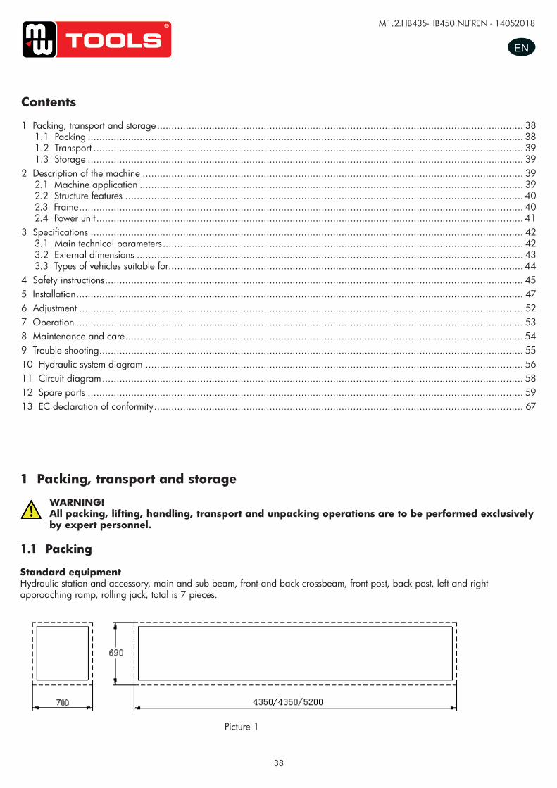
38
M1.2.HB435-HB450.NLFREN - 14052018
EN
1 Packing, transport and storage
WARNING!All packing, lifting, handling, transport and unpacking operations are to be performed exclusively by expert personnel.
1.1 Packing
Standard equipmentHydraulic station and accessory, main and sub beam, front and back crossbeam, front post, back post, left and right approaching ramp, rolling jack, total is 7 pieces.
Contents
1 Packing, transport and storage ............................................................................................................................... 381.1 Packing ....................................................................................................................................................... 381.2 Transport ..................................................................................................................................................... 391.3 Storage ....................................................................................................................................................... 39
2 Description of the machine .................................................................................................................................... 392.1 Machine application ..................................................................................................................................... 392.2 Structure features .......................................................................................................................................... 402.3 Frame .......................................................................................................................................................... 402.4 Power unit .................................................................................................................................................... 41
3 Specifications ...................................................................................................................................................... 423.1 Main technical parameters ............................................................................................................................. 423.2 External dimensions ...................................................................................................................................... 433.3 Types of vehicles suitable for........................................................................................................................... 44
4 Safety instructions ................................................................................................................................................. 455 Installation ........................................................................................................................................................... 476 Adjustment .......................................................................................................................................................... 527 Operation ........................................................................................................................................................... 538 Maintenance and care .......................................................................................................................................... 549 Trouble shooting ................................................................................................................................................... 5510 Hydraulic system diagram ................................................................................................................................... 5611 Circuit diagram .................................................................................................................................................. 5812 Spare parts ....................................................................................................................................................... 5913 EC declaration of conformity ................................................................................................................................ 67
Picture 1
UUSSEERR’’SS MMAANNUUAALL VV11..11 220011550099
- 3 -
1. Packing, transport and storage All packing, lifting, handling, transport and unpacking operations are to be performed exclusively
by expert personnel.
1.1. Packing
Standard equipment: hydraulic station and accessory, main and sub beam, front and back crossbeam, front post,
back post, left and right approaching ramp, rolling jack, total is 7 pieces.
Picture 1
1. 2. Transport:
Packing can be lifted or moved by lift trucks, cranes or bridge cranes. In case of slinging, a second person must always take care of the load, in order to avoid dangerous oscillations.
During loading and unloading operation, goods must be handled by vehicles or ships.
At the arrival of the goods, verify that all items specified in the delivery notes are included. In case of
missing parts possible defects or damage may due to transport operations.
If finding missing parts, possible defects or damage due to transport, one should examine damaged
cartons to verify the condition of damaged goods and missing parts, also the person in charge or the
carrier must be immediately informed.
The machine is heavy goods! Don’t take manpower load and unload and transporting way into consideration, the safety of working is important. Furthermore, during loading and unloading operation goods must be handled as shown in the picture. (Picture 2)
Picture 2 (Goods-lifted)
copy
righte
d do
cume
nt - a
ll rig
hts re
serv
ed b
y FB
C
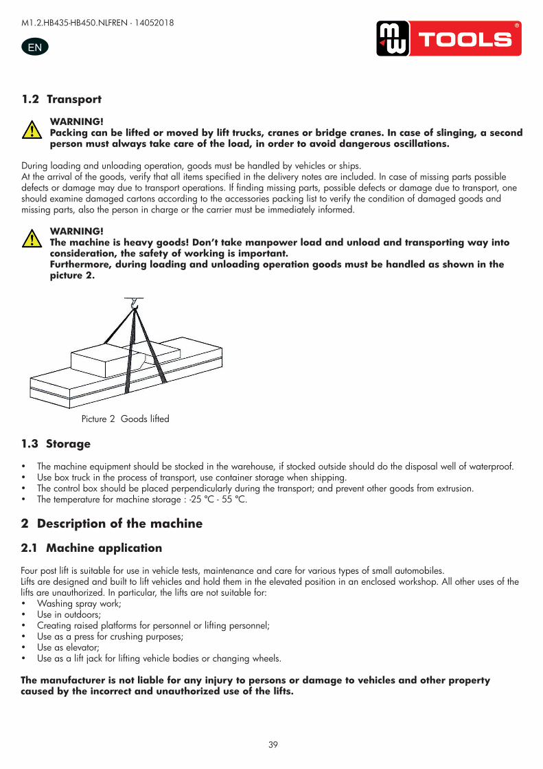
39
M1.2.HB435-HB450.NLFREN - 14052018
EN
1.2 Transport
WARNING!Packing can be lifted or moved by lift trucks, cranes or bridge cranes. In case of slinging, a second person must always take care of the load, in order to avoid dangerous oscillations.
During loading and unloading operation, goods must be handled by vehicles or ships.At the arrival of the goods, verify that all items specified in the delivery notes are included. In case of missing parts possible defects or damage may due to transport operations. If finding missing parts, possible defects or damage due to transport, one should examine damaged cartons according to the accessories packing list to verify the condition of damaged goods and missing parts, also the person in charge or the carrier must be immediately informed.
WARNING!The machine is heavy goods! Don’t take manpower load and unload and transporting way into consideration, the safety of working is important.Furthermore, during loading and unloading operation goods must be handled as shown in the picture 2.
UUSSEERR‟‟SS MMAANNUUAALL VV11..00 220011440088
- 4 -
1.2. Transport:
Packing can be lifted or moved by lift trucks, cranes or bridge cranes. In case of slinging, a second person must always take care of the load, in order to avoid dangerous oscillations.
During loading and unloading operation, goods must be handled by vehicles or ships.
At the arrival of the goods, verify that all items specified in the delivery notes are included. In case of
missing parts possible defects or damage may due to transport operations.
If finding missing parts, possible defects or damage due to transport, one should examine damaged
cartons according to <<Accessories Packing List>> to verify the condition of damaged goods and
missing parts, also the person in charge or the carrier must be immediately informed.
The machine is heavy goods! Don’t take manpower load and unload and transporting way into consideration, the safety of working is important. Furthermore, during loading and unloading operation goods must be handled as shown in the picture. (Picture 2)
Picture 2 (Goods-lifted)
1.3.Storage:
-The machine equipment should be stocked in the warehouse, if stocked outside should do the disposal
well of waterproof.
-Use box truck in the process of transport, use container storage when shipping.
-The control box should be placed perpendicularly during the transport; and prevent other goods from
extrusion.
-The temperature for machine storage : -25ºC-- 55ºC
2. Manual introduction This manual has been prepared for workshop personnel expert in the use of the lift operator and technicians responsible for routine maintenance fitter.
Picture 2 Goods lifted
1.3 Storage
• The machine equipment should be stocked in the warehouse, if stocked outside should do the disposal well of waterproof.• Use box truck in the process of transport, use container storage when shipping.• The control box should be placed perpendicularly during the transport; and prevent other goods from extrusion.• The temperature for machine storage : -25 ºC - 55 ºC.
2 Description of the machine
2.1 Machine application
Four post lift is suitable for use in vehicle tests, maintenance and care for various types of small automobiles.Lifts are designed and built to lift vehicles and hold them in the elevated position in an enclosed workshop. All other uses of the lifts are unauthorized. In particular, the lifts are not suitable for:• Washing spray work;• Use in outdoors;• Creating raised platforms for personnel or lifting personnel;• Use as a press for crushing purposes;• Use as elevator;• Use as a lift jack for lifting vehicle bodies or changing wheels.
The manufacturer is not liable for any injury to persons or damage to vehicles and other property caused by the incorrect and unauthorized use of the lifts.
copy
righte
d do
cume
nt - a
ll rig
hts re
serv
ed b
y FB
C
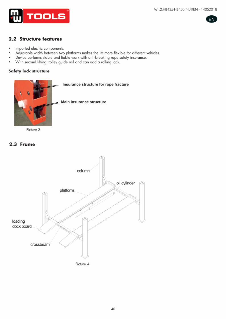
40
M1.2.HB435-HB450.NLFREN - 14052018
EN
2.2 Structure features
• Imported electric components.• Adjustable width between two platforms makes the lift more flexible for different vehicles.• Device performs stable and liable work with anti-breaking rope safety insurance. • With second lifting trolley guide rail and can add a rolling jack.
Safety lock structure
Picture 3
Picture 4
UUSSEERR’’SS MMAANNUUAALL VV11..11 220011550099
- 5 -
3.2. Structure Features -imported electric components.
-Adjustable width between two platforms makes the lift more flexible for different vehicles.
-Device performs stable and liable work with anti-breaking rope safety insurance.
-with second lifting trolley guide rail and can add a rolling jack.
Safety lock structure
3.3. Frame
3.4. Power unit
Under the control box is hydraulic oil tank and hydraulic pump, valve and other control system. On the
control box is electrical system.
Picture 3
Insurance structure for rope fracture
Main insurance structure
Picture 4
oil cylinder
column
platform
loadingdock board
crossbeam
2.3 Frame
copy
righte
d do
cume
nt - a
ll rig
hts re
serv
ed b
y FB
C
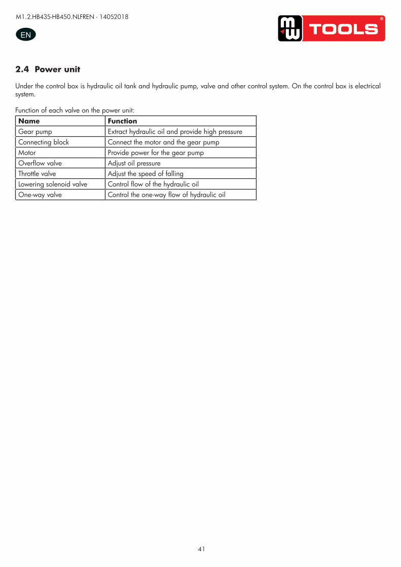
41
M1.2.HB435-HB450.NLFREN - 14052018
EN
2.4 Power unit
Under the control box is hydraulic oil tank and hydraulic pump, valve and other control system. On the control box is electrical system.
Function of each valve on the power unit:Name FunctionGear pump Extract hydraulic oil and provide high pressureConnecting block Connect the motor and the gear pumpMotor Provide power for the gear pumpOverflow valve Adjust oil pressureThrottle valve Adjust the speed of fallingLowering solenoid valve Control flow of the hydraulic oilOne-way valve Control the one-way flow of hydraulic oil
copy
righte
d do
cume
nt - a
ll rig
hts re
serv
ed b
y FB
C
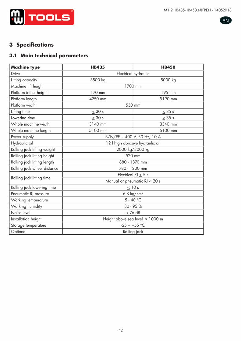
42
M1.2.HB435-HB450.NLFREN - 14052018
EN
3 Specifications
3.1 Main technical parameters
Machine type HB435 HB450Drive Electrical hydraulicLifting capacity 3500 kg 5000 kgMachine lift height 1700 mmPlatform initial height 170 mm 195 mmPlatform length 4250 mm 5190 mmPlatform width 530 mmLifting time < 30 s < 35 sLowering time < 30 s < 35 sWhole machine width 3140 mm 3340 mmWhole machine length 5100 mm 6100 mmPower supply 3/N/PE ~ 400 V, 50 Hz, 10 AHydraulic oil 12 l high abrasive hydraulic oilRolling jack lifting weight 2000 kg/3000 kgRolling jack lifting height 520 mmRolling jack lifting length 880 - 1370 mmRolling jack wheel distance 780 - 1200 mm
Rolling jack lifting timeElectrical RJ < 5 s
Manual or pneumatic RJ < 20 sRolling jack lowering time < 10 sPneumatic RJ pressure 6-8 kg/cm²Working temperature 5 - 40 °CWorking humidity 30 - 95 %Noise level < 76 dBInstallation height Height above sea level ≤ 1000 mStorage temperature -25 ~ +55 °COptional Rolling jack
copy
righte
d do
cume
nt - a
ll rig
hts re
serv
ed b
y FB
C
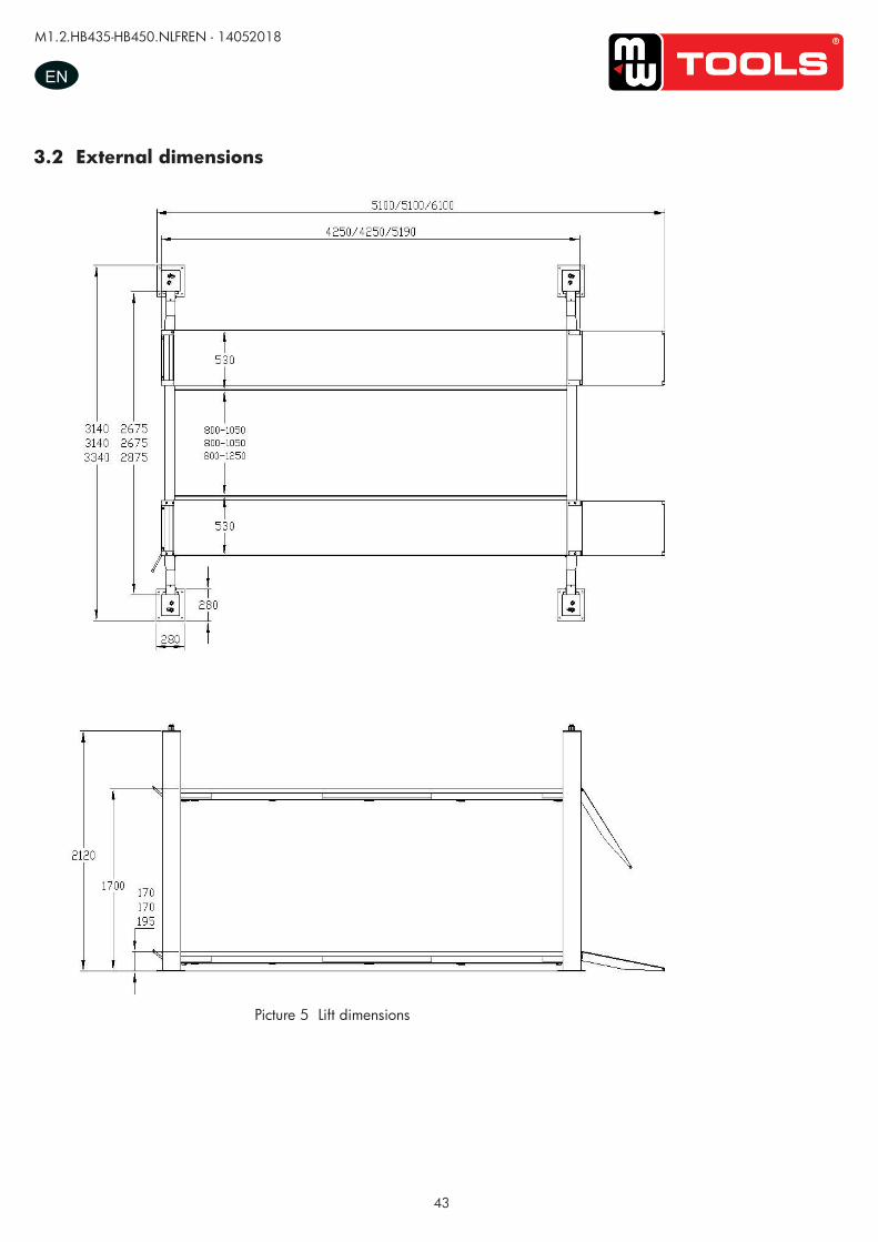
43
M1.2.HB435-HB450.NLFREN - 14052018
EN
3.2 External dimensions
Picture 5 Lift dimensions
UUSSEERR’’SS MMAANNUUAALL VV11..11 220011550099
- 7 -
4.2 External dimension drawing
Picture 5(lift dimension picture)
copy
righte
d do
cume
nt - a
ll rig
hts re
serv
ed b
y FB
C
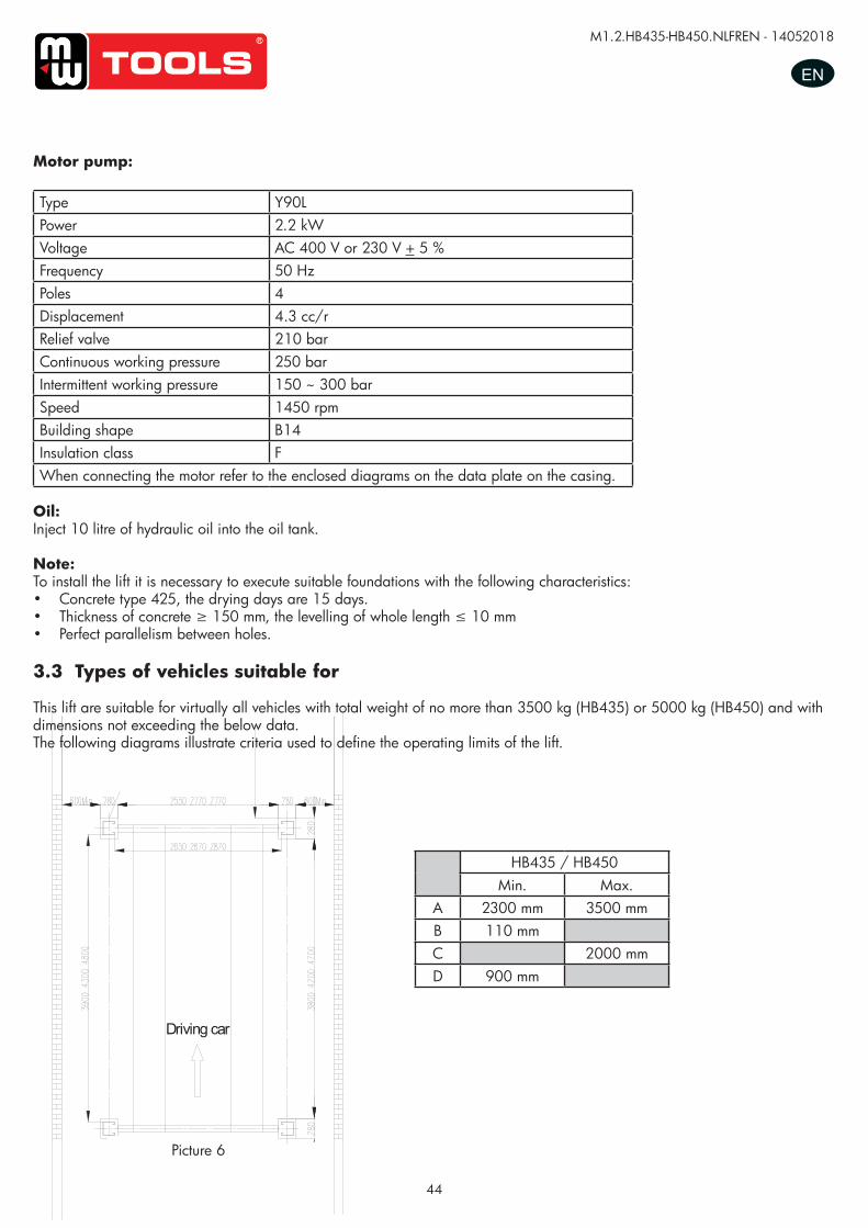
44
M1.2.HB435-HB450.NLFREN - 14052018
EN
HB435 / HB450Min. Max.
A 2300 mm 3500 mmB 110 mmC 2000 mmD 900 mm
Motor pump:
Type Y90LPower 2.2 kWVoltage AC 400 V or 230 V + 5 %Frequency 50 HzPoles 4Displacement 4.3 cc/rRelief valve 210 barContinuous working pressure 250 barIntermittent working pressure 150 ~ 300 barSpeed 1450 rpmBuilding shape B14Insulation class FWhen connecting the motor refer to the enclosed diagrams on the data plate on the casing.
Oil:Inject 10 litre of hydraulic oil into the oil tank.
Note:To install the lift it is necessary to execute suitable foundations with the following characteristics:• Concrete type 425, the drying days are 15 days.• Thickness of concrete ≥ 150 mm, the levelling of whole length ≤ 10 mm• Perfect parallelism between holes.
3.3 Types of vehicles suitable for
This lift are suitable for virtually all vehicles with total weight of no more than 3500 kg (HB435) or 5000 kg (HB450) and with dimensions not exceeding the below data. The following diagrams illustrate criteria used to define the operating limits of the lift.
UUSSEERR’’SS MMAANNUUAALL VV11..11 220011550099
- 9 -
Driving car
The thickness and leveling of the base concrete are essential and the leveling adjustment ability of the machine itself cannot be relied upon to excessively. Types of vehicle suitable for being lifted and overall dimensions.
4.3. Types of vehicles suitable for
Lift are suitable for virtually all vehicles with total weight of no more than 3500kg/4000kg/5000kg and with
dimensions not exceeding the below data.
The following diagrams illustrate criteria used to define the operating limits of the lift.
Caution: The lower parts of the vehicle underbody could interfere with structural parts of the lift, take particular parts of the sports car.
The lift will also handle customized or non-standard vehicles, provided they are within the maximum specified
carrying capacity.
Also the personnel safety zone must be defined in relation to vehicle with unusual dimensions.
3.5T/4T/5T
Min.(mm) Max.(mm)
A 2300 3500/3500/4500
B 110
C 2000
D 900
Picture 6Picture 6
copy
righte
d do
cume
nt - a
ll rig
hts re
serv
ed b
y FB
C
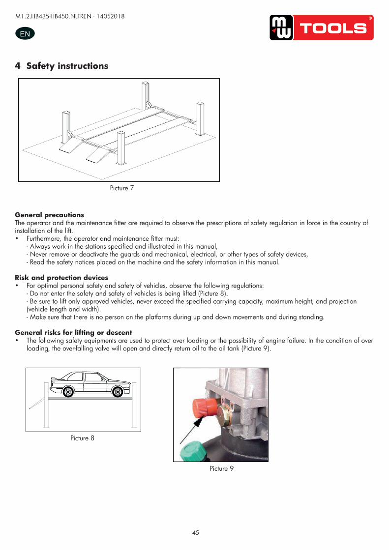
45
M1.2.HB435-HB450.NLFREN - 14052018
EN
4 Safety instructions
Picture 7
UUSSEERR’’SS MMAANNUUAALL VV11..11 220011550099
- 10 -
Read this chapter carefully and completely since important information for the safety of the operator or others in case of improper use of the lift is included.
In the following text there are clear explanations regarding certain situations of risk or danger that may
arise during the operation or maintenance of the lift, the safety device installed and the correct use of
such systems, residual risks and operative procedures to use (general specific precautions to eliminate
potential hazards).
Lifts are designed and built to lift vehicles and hold them in the elevated position in an enclosed workshop. All other uses of the lifts are unauthorized. In particular, the lifts are not suitable for: -Washing spray work; -Use in outdoors; -Creating raised platforms for personnel or lifting personnel; -Use as a press for crushing purposes; -Use as elevator; -Use as a lift jack for lifting vehicle bodies or changing wheels.
The manufacturer is not liable for any injury to persons or damage to vehicles and other property caused
by the incorrect and unauthorized use of the lifts.
During lifting and descent, the operator must remain in the control station as the diagrams illustrated.
As the diagrams illustrated, the presence of persons inside the danger zone indicated is strictly
prohibited. During operations persons are admitted to the area beneath the vehicle only when the vehicle
is already in the elevated position, when the platforms are stationary, and when the mechanical safety
devices are firmly engaged (e.g.: the safety gear is completely locked).
Do not use the lift without protection devices or with the protection devices inhibited.
Failure to comply with this regulation can cause serious injury to persons, and irreparable damage to the
lift and the vehicle being lifted.
5. Safety
Picture 7
General precautionsThe operator and the maintenance fitter are required to observe the prescriptions of safety regulation in force in the country of installation of the lift.• Furthermore, the operator and maintenance fitter must:
- Always work in the stations specified and illustrated in this manual, - Never remove or deactivate the guards and mechanical, electrical, or other types of safety devices, - Read the safety notices placed on the machine and the safety information in this manual.
Risk and protection devices• For optimal personal safety and safety of vehicles, observe the following regulations:
- Do not enter the safety and safety of vehicles is being lifted (Picture 8). - Be sure to lift only approved vehicles, never exceed the specified carrying capacity, maximum height, and projection (vehicle length and width). - Make sure that there is no person on the platforms during up and down movements and during standing.
General risks for lifting or descent• The following safety equipments are used to protect over loading or the possibility of engine failure. In the condition of over
loading, the over-falling valve will open and directly return oil to the oil tank (Picture 9).
Picture 8
UUSSEERR’’SS MMAANNUUAALL VV11..11 220011550099
- 11 -
General precautions The operator and the maintenance fitter are required to observe the prescriptions of safety regulation in
force in the country of installation of the lift.
Furthermore, the operator and maintenance fitter must:
-Always work in the stations specified and illustrated in this manual;
-Never remove or deactivate the guards and mechanical, electrical, or other types of safety devices;
-Read the safety notices placed on the machine and the safety information in this manual.
In the manual all safety notices are shown as follows: Warning: indicates following operations that are unsafe and can cause minor injury to persons and
damage the lift, the vehicle or other property.
Risk and protection devices
For optimal personal safety and safety of vehicles, observe the following regulations:
-Do not enter the safety and safety of vehicles is being lifted. (Picture 8)
-Be sure to lift only approved vehicles, never exceed the specified carrying capacity, maximum height,
and projection (vehicle length and width);
-Make sure that there is no person on the platforms during up and down movements and during
standing.(Picture 8)
General risks for lifting or descent The following safety equipments are used to protect over loading or the possibility of engine failure.
In the condition of over loading, the over-falling valve will open and directly return oil to the oil tank.
(Picture 9)
Picture 8
Picture 9
UUSSEERR’’SS MMAANNUUAALL VV11..11 220011550099
- 11 -
General precautions The operator and the maintenance fitter are required to observe the prescriptions of safety regulation in
force in the country of installation of the lift.
Furthermore, the operator and maintenance fitter must:
-Always work in the stations specified and illustrated in this manual;
-Never remove or deactivate the guards and mechanical, electrical, or other types of safety devices;
-Read the safety notices placed on the machine and the safety information in this manual.
In the manual all safety notices are shown as follows: Warning: indicates following operations that are unsafe and can cause minor injury to persons and
damage the lift, the vehicle or other property.
Risk and protection devices
For optimal personal safety and safety of vehicles, observe the following regulations:
-Do not enter the safety and safety of vehicles is being lifted. (Picture 8)
-Be sure to lift only approved vehicles, never exceed the specified carrying capacity, maximum height,
and projection (vehicle length and width);
-Make sure that there is no person on the platforms during up and down movements and during
standing.(Picture 8)
General risks for lifting or descent The following safety equipments are used to protect over loading or the possibility of engine failure.
In the condition of over loading, the over-falling valve will open and directly return oil to the oil tank.
(Picture 9)
Picture 8
Picture 9 Picture 9
copy
righte
d do
cume
nt - a
ll rig
hts re
serv
ed b
y FB
C
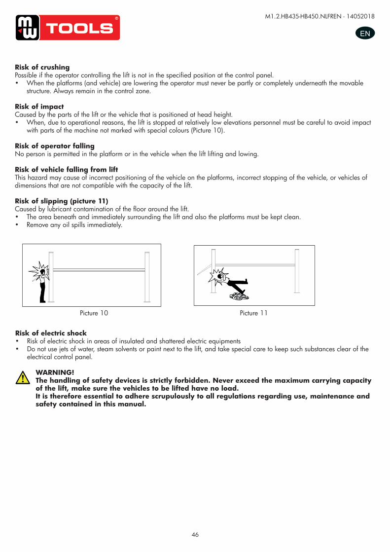
46
M1.2.HB435-HB450.NLFREN - 14052018
EN
Picture 10 Picture 11
Risk of electric shock• Risk of electric shock in areas of insulated and shattered electric equipments• Do not use jets of water, steam solvents or paint next to the lift, and take special care to keep such substances clear of the
electrical control panel.
WARNING!The handling of safety devices is strictly forbidden. Never exceed the maximum carrying capacity of the lift, make sure the vehicles to be lifted have no load.It is therefore essential to adhere scrupulously to all regulations regarding use, maintenance and safety contained in this manual.
Risk of crushingPossible if the operator controlling the lift is not in the specified position at the control panel.• When the platforms (and vehicle) are lowering the operator must never be partly or completely underneath the movable
structure. Always remain in the control zone.
Risk of impactCaused by the parts of the lift or the vehicle that is positioned at head height.• When, due to operational reasons, the lift is stopped at relatively low elevations personnel must be careful to avoid impact
with parts of the machine not marked with special colours (Picture 10).
Risk of operator fallingNo person is permitted in the platform or in the vehicle when the lift lifting and lowing.
Risk of vehicle falling from liftThis hazard may cause of incorrect positioning of the vehicle on the platforms, incorrect stopping of the vehicle, or vehicles of dimensions that are not compatible with the capacity of the lift.
Risk of slipping (picture 11)Caused by lubricant contamination of the floor around the lift.• The area beneath and immediately surrounding the lift and also the platforms must be kept clean.• Remove any oil spills immediately.
UUSSEERR’’SS MMAANNUUAALL VV11..11 220011550099
- 12 -
Risk of crushing Possible if the operator controlling the lift is not I the specified position at the control panel.
When the platforms (and vehicle) are lowering the operator must never be partly or completely underneath the
movable structure. Always remain in the control zone.
Risk of impact (Picture 10) Caused by the parts of the lift or the vehicle that is positioned at head height.
When, due to operational reasons, the lift is stopped at relatively low elevations personnel must be careful to avoid
impact with parts of the machine not marked with special color.
Risk of operator falling No person is permitted in the platform or in the vehicle when the lift lifting and lowing,
Risk of vehicle falling from lift This hazard may cause of incorrect positioning of the vehicle on the platforms, incorrect stopping of the vehicle, or
vehicles of dimensions that are not compatible with the capacity of the lift.
Never attempt to perform test by driving the vehicle while it is on the platforms Never leave objects in the lowering area of the movable parts of the lift.
Risk of slipping(Picture 11) Caused by lubricant contamination of the floor around the lift.
The area beneath and immediately surrounding the lift and also the platforms must be kept clean.
Remove any oil spills immediately.
Picture 10
Picture 11
copy
righte
d do
cume
nt - a
ll rig
hts re
serv
ed b
y FB
C
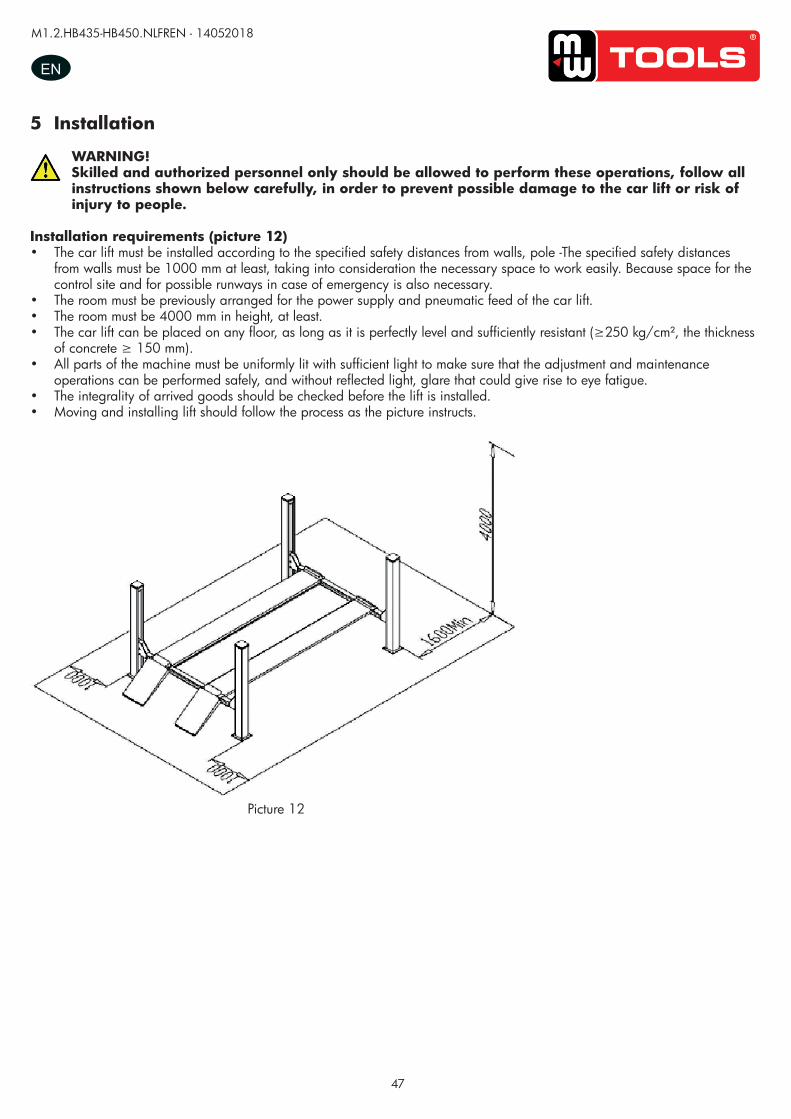
47
M1.2.HB435-HB450.NLFREN - 14052018
EN
5 Installation
WARNING!Skilled and authorized personnel only should be allowed to perform these operations, follow all instructions shown below carefully, in order to prevent possible damage to the car lift or risk of injury to people.
Installation requirements (picture 12)• The car lift must be installed according to the specified safety distances from walls, pole -The specified safety distances
from walls must be 1000 mm at least, taking into consideration the necessary space to work easily. Because space for the control site and for possible runways in case of emergency is also necessary.
• The room must be previously arranged for the power supply and pneumatic feed of the car lift.• The room must be 4000 mm in height, at least.• The car lift can be placed on any floor, as long as it is perfectly level and sufficiently resistant (≥250 kg/cm², the thickness
of concrete ≥ 150 mm).• All parts of the machine must be uniformly lit with sufficient light to make sure that the adjustment and maintenance
operations can be performed safely, and without reflected light, glare that could give rise to eye fatigue.• The integrality of arrived goods should be checked before the lift is installed.• Moving and installing lift should follow the process as the picture instructs.
Picture 12
UUSSEERR’’SS MMAANNUUAALL VV11..11 220011550099
- 13 -
Risk of electric shock Risk of electric shock in areas of the lift housing electrical wiring.
Do not use jets of water, steam solvents or paint next to the lift, and take special care to keep such substances
clear of the electrical control panel.
The handling of safety devices is strictly forbidden. Never exceed the maximum carrying capacity of the lift, make sure the vehicles to be lifted have no load. It is therefore essential to adhere scrupulously to all regulations regarding use, maintenance and safety contained in this manual.
6. Installation
Skilled and authorized personnel only should be allowed to perform these operations, follow all instructions shown below carefully, in order to prevent possible damage to the car lift or risk of injury to people.
Installation requirements (Picture 12) The car lift must be installed according to the specified safety distances from walls must be 1000 mm at least,
taking into consideration of the necessary space to work easily. Further space for the control site and for possible
runways in case of emergency is also necessary; the room must be previously arranged for the power supply and
pneumatic feed of the car lift. The room must be 4000 mm in height, at least, the car lift can be placed on any floor,
as long as it is perfectly level and sufficiently resistant.(≥250kg/cm2)
-All parts of the machine must be uniformly lit with sufficient light to make sure that the adjustment and
maintenance operations specified in the manual can be performed safely, and without areas of shadow, reflected
light, glare and avoiding all situations that could give rise to eye fatigue.
-The lighting must be installed in accordance with the laws in force in the place of installation.
-the thickness and leveling of the base concrete are essential
-thickness of concrete≥150mm, the leveling of whole length≤10mm.
Picture 12
copy
righte
d do
cume
nt - a
ll rig
hts re
serv
ed b
y FB
C
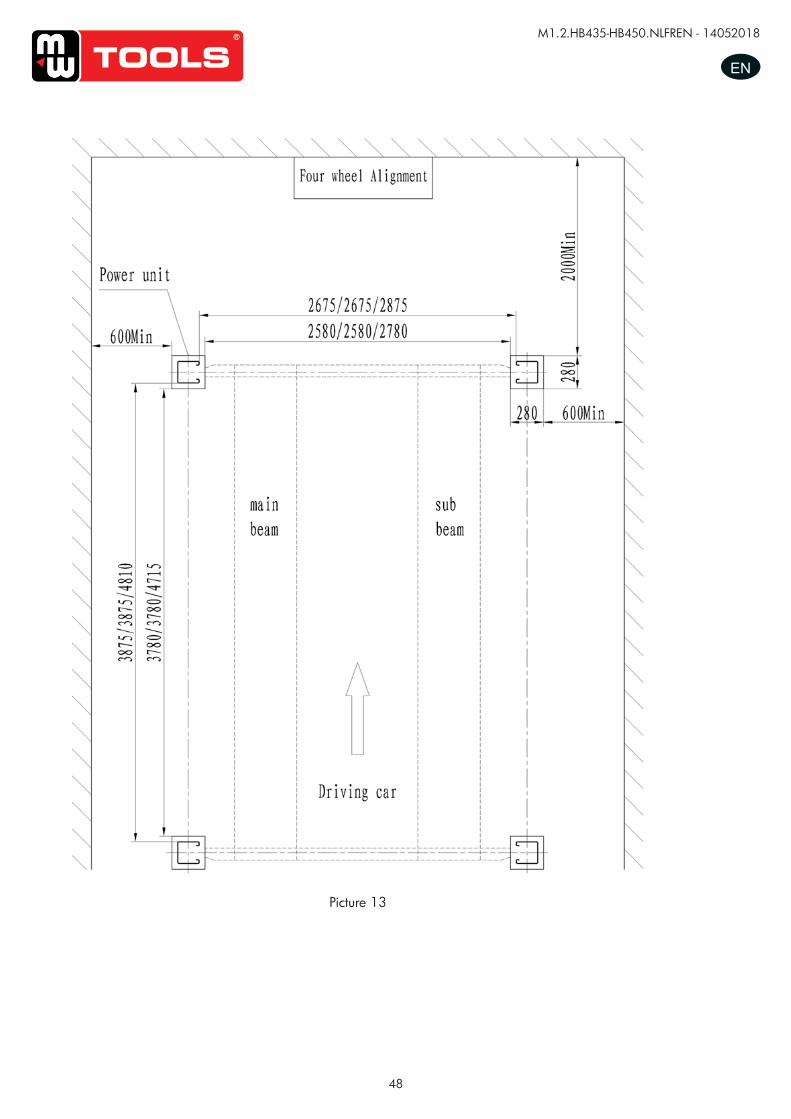
48
M1.2.HB435-HB450.NLFREN - 14052018
ENUUSSEERR’’SS MMAANNUUAALL VV11..11 220011550099
- 14 -
Installation scheme for four post lift
Picture 13
Picture 13
copy
righte
d do
cume
nt - a
ll rig
hts re
serv
ed b
y FB
C
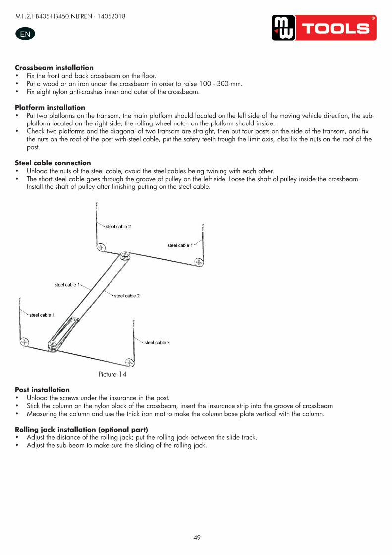
49
M1.2.HB435-HB450.NLFREN - 14052018
EN
Crossbeam installation• Fix the front and back crossbeam on the floor.• Put a wood or an iron under the crossbeam in order to raise 100 - 300 mm.• Fix eight nylon anti-crashes inner and outer of the crossbeam.
Platform installation• Put two platforms on the transom, the main platform should located on the left side of the moving vehicle direction, the sub-
platform located on the right side, the rolling wheel notch on the platform should inside.• Check two platforms and the diagonal of two transom are straight, then put four posts on the side of the transom, and fix
the nuts on the roof of the post with steel cable, put the safety teeth trough the limit axis, also fix the nuts on the roof of the post.
Steel cable connection• Unload the nuts of the steel cable, avoid the steel cables being twining with each other.• The short steel cable goes through the groove of pulley on the left side. Loose the shaft of pulley inside the crossbeam.
Install the shaft of pulley after finishing putting on the steel cable.
UUSSEERR’’SS MMAANNUUAALL VV11..11 220011550099
- 15 -
Crossbeam installation -fix the front and back crossbeam on the floor.
-Put a wood or an iron under the crossbeam in order to raise 100-300mm.
-fix eight nylon anti-crashes inner and outer of the crossbeam.
Platform installation: -Put two platforms on the transom, the main platform should located on the left side of the moving vehicle direction,
the sub-platform located on the right side, the rolling wheel notch on the platform should inside.
-check two platforms and the diagonal of two transom are straight, then put four posts on the side of the transom,
and fix the nuts on the roof of the post with steel cable, put the safety teeth trough the limit axis, also fix the nuts on
the roof of the post.
Steel cable connection: -Unload the nuts of the steel cable, avoid the steel cables being twining with each other.
- The short steel cable goes through the groove of pulley on the left side. Loose the shaft of pulley inside the
crossbeam. Install the shaft of pulley after finishing putting on the steel cable.
Post installation: -Unload the screws under the insurance in the post.
-stick the column on the nylon block of the crossbeam, insert the insurance strip into the groove of crossbeam
-measuring the column and use the thick iron mat to make the column base plate vertical with the column.
Rolling jack installation(optional part):
-adjust the distance of the rolling jack; put the rolling jack between the slide track.
-adjust the sub beam to make sure the sliding of the rolling jack.
Picture 14 Picture 14
Post installation• Unload the screws under the insurance in the post.• Stick the column on the nylon block of the crossbeam, insert the insurance strip into the groove of crossbeam• Measuring the column and use the thick iron mat to make the column base plate vertical with the column.
Rolling jack installation (optional part)• Adjust the distance of the rolling jack; put the rolling jack between the slide track.• Adjust the sub beam to make sure the sliding of the rolling jack.
copy
righte
d do
cume
nt - a
ll rig
hts re
serv
ed b
y FB
C
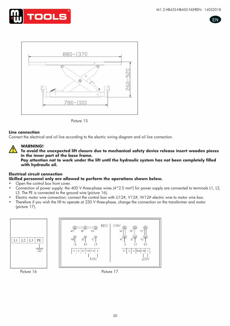
50
M1.2.HB435-HB450.NLFREN - 14052018
EN
UUSSEERR’’SS MMAANNUUAALL VV11..11 220011550099
- 16 -
Line connection Connect the electrical and oil line according to the electric wiring diagram and oil line connection
To avoid the unexpected lift closure due to mechanical safety device release insert wooden pieces in the inner part of the base frame. Pay attention not to work under the lift until the hydraulic system has not been completely filled with hydraulic oil.
Electrical circuit connection:
According to the electric connection.
Skilled personnel only are allowed to perform the operations shown below.
-open the control box front cover
-connection of power supply: the 400 three-phase five-wires (4*2.5mm2) for power supply are connected to
terminals 1#, 2#, 3#.The PE is connected to the ground wire.(Picture 16)
-Electric motor wire connection: connect the control box with U12﹟、V12#、W12# electric wire to motor wire box.
-therefore if you wish the lift to operate at 230V three-phase, change the connection on the transformer and motor.
(Picture 17)
.
L1 L2 L3 PE
Picture 15
Picture 16 Picture 17
Picture 15
Picture 16 Picture 17
Line connectionConnect the electrical and oil line according to the electric wiring diagram and oil line connection.
WARNING!To avoid the unexpected lift closure due to mechanical safety device release insert wooden pieces in the inner part of the base frame.Pay attention not to work under the lift until the hydraulic system has not been completely filled with hydraulic oil.
Electrical circuit connectionSkilled personnel only are allowed to perform the operations shown below.• Open the control box front cover.• Connection of power supply: the 400 V three-phase wires (4*2.5 mm²) for power supply are connected to terminals L1, L2,
L3. The PE is connected to the ground wire (picture 16).• Electric motor wire connection: connect the control box with U12#, V12#, W12# electric wire to motor wire box.• Therefore if you wish the lift to operate at 230 V three-phase, change the connection on the transformer and motor
(picture 17).
copy
righte
d do
cume
nt - a
ll rig
hts re
serv
ed b
y FB
C
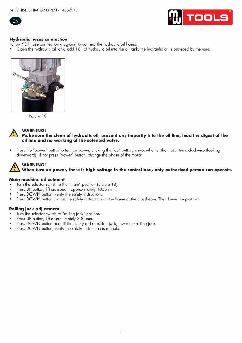
51
M1.2.HB435-HB450.NLFREN - 14052018
ENUUSSEERR’’SS MMAANNUUAALL VV11..11 220011550099
- 17 -
Hydraulic hoses connection:
Follow <<oil hose connection diagram >> to connect the hydraulic oil hoses
Open the hydraulic oil tank, add 18L of hydraulic oil into the oil tank, the hydraulic oil is provided by the user.
Make sure the clean of hydraulic oil, prevent any impurity into the oil line, lead the digest of the oil line and no working of the solenoid valve. -press the “power” button to turn on power, clicking the “up” button, check whether the motor turns clockwise
(looking downward), if not press “power” button, change the phase of the motor.
When turn on power, there is high voltage in the control box, only authorized person can operate.
Main machine adjustment -Turn the selector switch to the “main” position. (Picture18)
-press “up” button SB1, lift crossbeam approximately 1000mm.
-press “down” button SB2, verity the safety instruction.
-press “down” button SB2, adjust the safety instruction on the frame of the crossbeam. Then lower the platform.
Rolling jack adjustment -turn the selector switch to “rolling jack” position.
-press “up” button SB1, lift approximately 300mm.
-press “down” button SB2 and lift the safety rod of rolling jack, lower the rolling jack.
-press “down” button SB2, verify the safety instruction is reliable.
Picture 18
Hydraulic hoses connectionFollow “Oil hose connection diagram” to connect the hydraulic oil hoses.• Open the hydraulic oil tank, add 18 l of hydraulic oil into the oil tank, the hydraulic oil is provided by the user.
Picture 18
WARNING!Make sure the clean of hydraulic oil, prevent any impurity into the oil line, lead the digest of the oil line and no working of the solenoid valve.
• Press the “power” button to turn on power, clicking the “up” button, check whether the motor turns clockwise (looking downward), if not press “power” button, change the phase of the motor.
WARNING!When turn on power, there is high voltage in the control box, only authorized person can operate.
Main machine adjustment• Turn the selector switch to the “main” position (picture 18).• Press UP button, lift crossbeam approximately 1000 mm.• Press DOWN button, verity the safety instruction.• Press DOWN button, adjust the safety instruction on the frame of the crossbeam. Then lower the platform.
Rolling jack adjustment• Turn the selector switch to “rolling jack” position.• Press UP button, lift approximately 300 mm.• Press DOWN button and lift the safety rod of rolling jack, lower the rolling jack.• Press DOWN button, verify the safety instruction is reliable.
copy
righte
d do
cume
nt - a
ll rig
hts re
serv
ed b
y FB
C
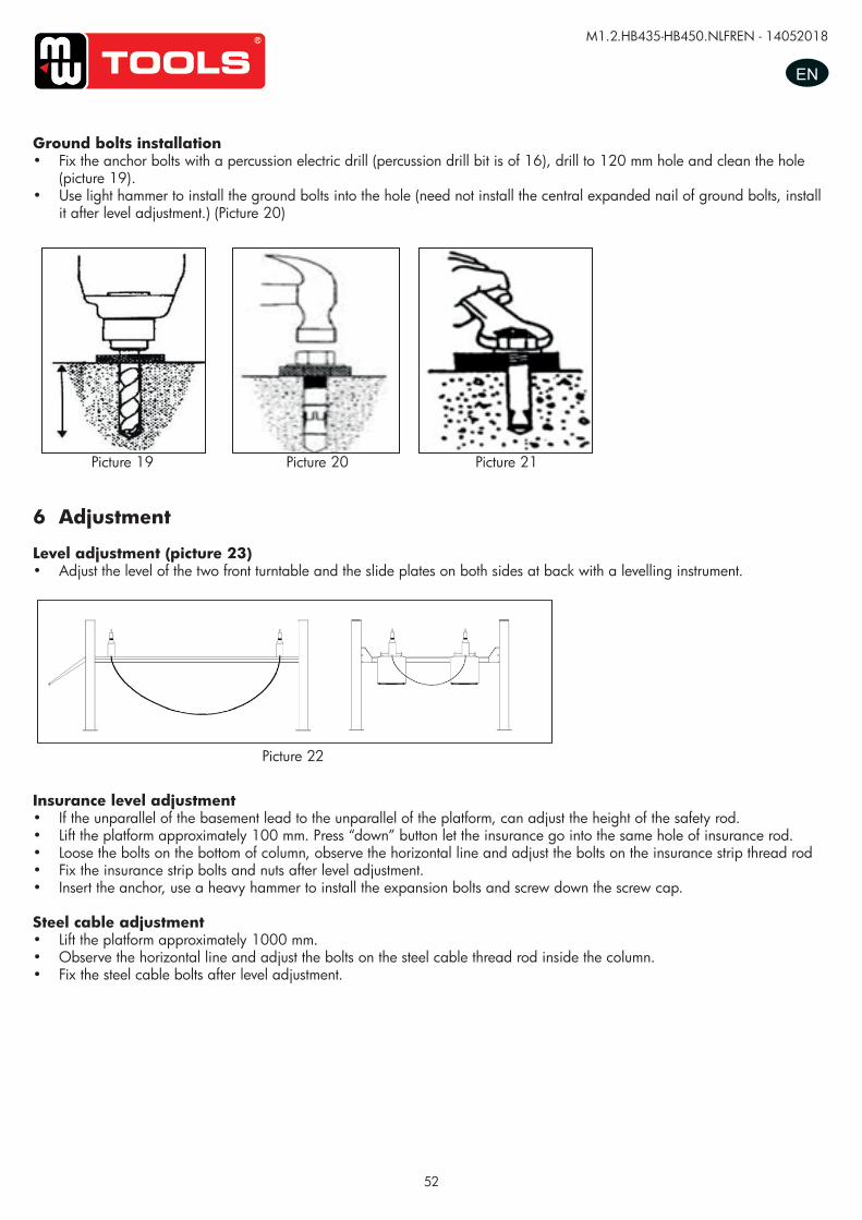
52
M1.2.HB435-HB450.NLFREN - 14052018
EN
Ground bolts installation• Fix the anchor bolts with a percussion electric drill (percussion drill bit is of 16), drill to 120 mm hole and clean the hole
(picture 19).• Use light hammer to install the ground bolts into the hole (need not install the central expanded nail of ground bolts, install
it after level adjustment.) (Picture 20)
UUSSEERR‟‟SS MMAANNUUAALL VV11..00 220011440088
- 15 -
Platform Installation:
-Place two lift platforms on the position of the location
-The bottom of oil cylinder is located in the frontage of machine (the direction of getting on the vehicle)
-Use fork car or other lifting equipments to lift the platform (Picture17) and make sure that the safety
equipment of machine is both turned on and locked.
Picture 17
To avoid failure of machine safety equipment, can insert a wood in the middle part of joint-pole. Prohibit working beneath the lift when hydraulic system is not completely equipped with hydraulic oil and take the action of up and down operations. -When moving the lift platform, adjust the space between two platforms; make sure that the two platforms are parallel.
Ground bolts installation
The ground bolts installation must start after the expiry date on the maintenance of concert, otherwise, it
will affect the quality of solidity.
-Adjust the parallel of the platform and the distance of two platform as Picture 18 requires.
-Fix the anchor bolts with a percussion electric drill (percussion drill bit is of 16), drill to 120mm hole and
clean the hole.(Picture 18) -Use light hammer to install the ground bolts into the hole (need not install the central expanded nail of
ground bolts, install it after level adjustment.) (Picture 19)
Picture 18 Picture 19 Picture 20
Picture 19 Picture 20 Picture 21
6 Adjustment
Level adjustment (picture 23)• Adjust the level of the two front turntable and the slide plates on both sides at back with a levelling instrument.
Picture 22
UUSSEERR’’SS MMAANNUUAALL VV11..11 220011550099
- 18 -
Anchor bolts installation -Fix the anchor bolts with a percussion electric drill (percussion drill bit is of 16), drill to 120mm hole and
clean the hole.(Picture 20) -Use light hammer to install the ground bolts into the hole (need not install the central expanded nail of
ground bolts, install it after level adjustment.) (Picture 21)
7. Adjustment
Level adjustment (Picture 23)
-adjust the level of the two front turntable and the slide plates on both sides at back with a leveling instrument.
Insurance level adjustment.
-if the unparallel of the basement lead to the unparallel of the platform, can adjust the height of the safety rod.
-lift the platform approximately 100mm; press “down” button let the insurance go into the same hole of insurance
rod.
-loose the bolts on the bottom of column, observe the horizontal line and adjust the bolts on the insurance strip
thread rod
-fix the insurance strip bolts and nuts after level adjustment.
-insert the anchor, use a heavy hammer to install the expansion bolts and screw down the screw cap
Steel cable adjustment
-lift the platform approximately 1000mm.
-observe the horizontal line and adjust the bolts on the steel cable thread rod inside the column.
-fix the steel cable bolts after level adjustment.
Picture 20 Picture 21
Picture 23
Picture 22
Insurance level adjustment• If the unparallel of the basement lead to the unparallel of the platform, can adjust the height of the safety rod.• Lift the platform approximately 100 mm. Press “down” button let the insurance go into the same hole of insurance rod.• Loose the bolts on the bottom of column, observe the horizontal line and adjust the bolts on the insurance strip thread rod• Fix the insurance strip bolts and nuts after level adjustment.• Insert the anchor, use a heavy hammer to install the expansion bolts and screw down the screw cap.
Steel cable adjustment• Lift the platform approximately 1000 mm.• Observe the horizontal line and adjust the bolts on the steel cable thread rod inside the column.• Fix the steel cable bolts after level adjustment.
copy
righte
d do
cume
nt - a
ll rig
hts re
serv
ed b
y FB
C
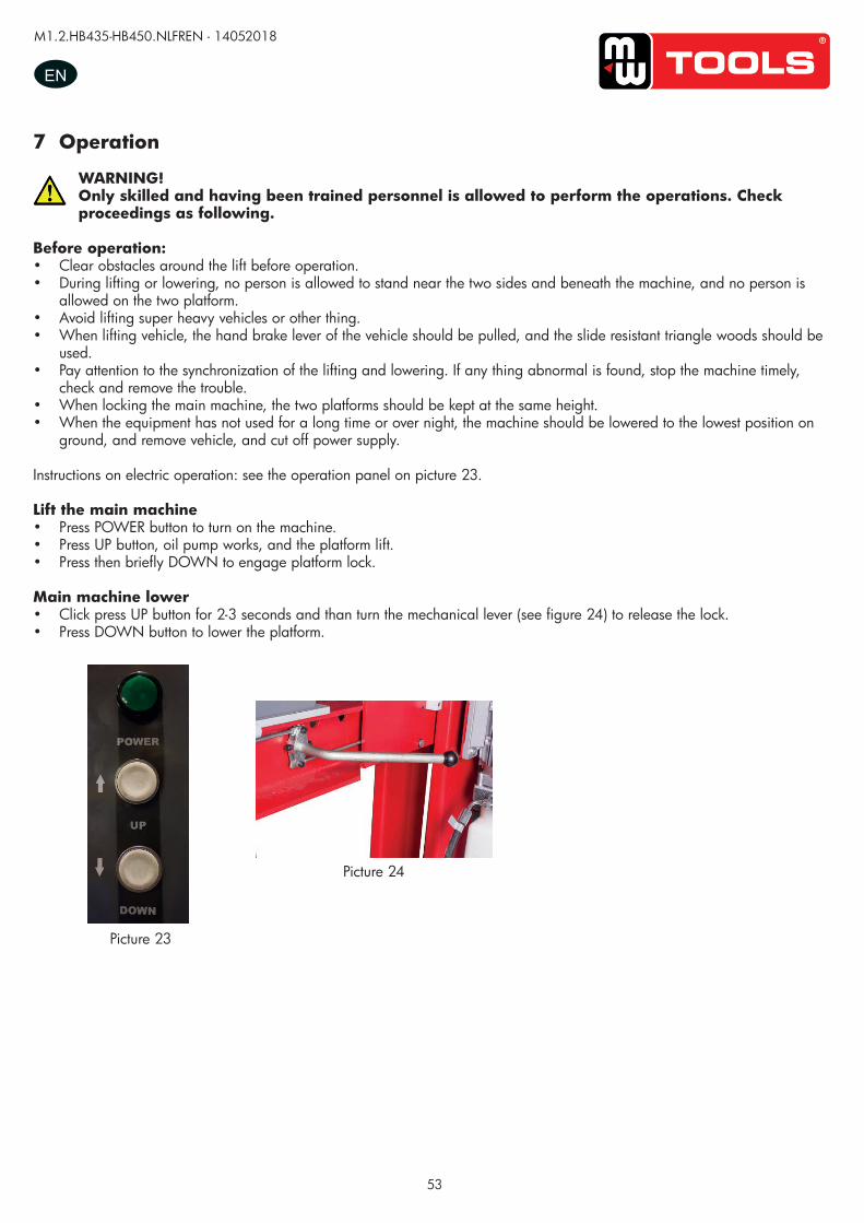
53
M1.2.HB435-HB450.NLFREN - 14052018
EN
7 Operation
WARNING!Only skilled and having been trained personnel is allowed to perform the operations. Check proceedings as following.
Before operation:• Clear obstacles around the lift before operation.• During lifting or lowering, no person is allowed to stand near the two sides and beneath the machine, and no person is
allowed on the two platform.• Avoid lifting super heavy vehicles or other thing.• When lifting vehicle, the hand brake lever of the vehicle should be pulled, and the slide resistant triangle woods should be
used.• Pay attention to the synchronization of the lifting and lowering. If any thing abnormal is found, stop the machine timely,
check and remove the trouble.• When locking the main machine, the two platforms should be kept at the same height.• When the equipment has not used for a long time or over night, the machine should be lowered to the lowest position on
ground, and remove vehicle, and cut off power supply.
Instructions on electric operation: see the operation panel on picture 23.
Lift the main machine• Press POWER button to turn on the machine.• Press UP button, oil pump works, and the platform lift.• Press then briefly DOWN to engage platform lock.
Main machine lower• Click press UP button for 2-3 seconds and than turn the mechanical lever (see figure 24) to release the lock.• Press DOWN button to lower the platform.
Picture 23
Picture 24
copy
righte
d do
cume
nt - a
ll rig
hts re
serv
ed b
y FB
C
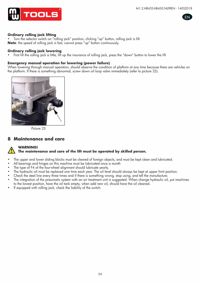
54
M1.2.HB435-HB450.NLFREN - 14052018
EN
Ordinary rolling jack lifting• Turn the selector switch on “rolling jack” position, clicking “up” button, rolling jack is lift.Note: the speed of rolling jack is fast, cannot press “up” button continuously.
Ordinary rolling jack lowering• First lift the rolling jack a little, lift up the insurance of rolling jack, press the “down” button to lower the lift
Emergency manual operation for lowering (power failure)When lowering through manual operation, should observe the condition of platform at any time because there are vehicles on the platform. If there is something abnormal, screw down oil loop valve immediately (refer to picture 25).
UUSSEERR’’SS MMAANNUUAALL VV11..11 220011550099
- 20 -
Only authorized person can operate, doing alignment only after “locking” process.
Ordinary rolling jack lifting -turn the selector switch on “rolling jack” position, clicking “up” button, rolling jack is lift.
Note: the speed of rolling jack is fast, cannot press “up” button continuously.
Ordinary rolling jack lowering -First lift the rolling jack a little, lift up the insurance of rolling jack, press the “down” button to lower the lift
Emergency manual operation for lowering (power failure) When lowering through manual operation, should observe the condition of platform at any time because
there are vehicles on the platform. If there is something abnormal, screw down oil loop valve
immediately.(refer to Picture 26)
The process of manual operation
9.Maintenance and care The maintenance and care of the lift must be operated by skilled person.
-the upper and lower sliding blocks must be cleared of foreign objects, and must be kept clean and lubricated. -all bearings and hinges on this machine must be lubricated once a month
-the type of F4 of the four-wheel alignment should lubricate yearly.
-the hydraulic oil must be replaced one time each year. The oil level should always be kept at upper limit position.
-check the steel line every three times and if there is something wrong, stop using, and tell the manufacture.
-the integration of the pneumatic system with an air treatment unit is suggested.
When change hydraulic oil, put machines to the lowest position, have the oil tank empty, when add new oil, should
have the oil cleaned.
-if equipped with rolling jack, check the liability of the switch.
Picture 26 Picture 25
8 Maintenance and care
WARNING!The maintenance and care of the lift must be operated by skilled person.
• The upper and lower sliding blocks must be cleared of foreign objects, and must be kept clean and lubricated.• All bearings and hinges on this machine must be lubricated once a month• The type of F4 of the four-wheel alignment should lubricate yearly.• The hydraulic oil must be replaced one time each year. The oil level should always be kept at upper limit position.• Check the steel line every three times and if there is something wrong, stop using, and tell the manufacture.• The integration of the pneumatic system with an air treatment unit is suggested. When change hydraulic oil, put machines
to the lowest position, have the oil tank empty, when add new oil, should have the oil cleaned.• If equipped with rolling jack, check the liability of the switch.
copy
righte
d do
cume
nt - a
ll rig
hts re
serv
ed b
y FB
C
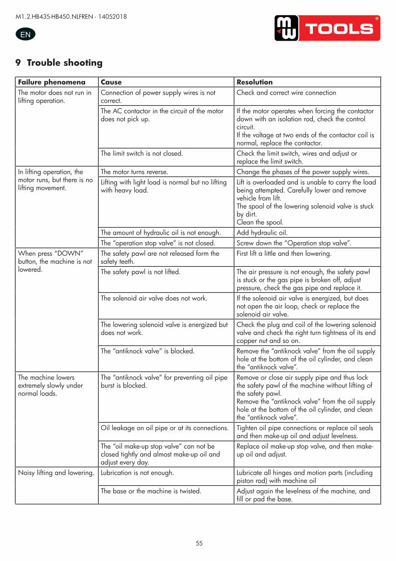
55
M1.2.HB435-HB450.NLFREN - 14052018
EN
9 Trouble shooting
Failure phenomena Cause ResolutionThe motor does not run in lifting operation.
Connection of power supply wires is not correct.
Check and correct wire connection
The AC contactor in the circuit of the motor does not pick up.
If the motor operates when forcing the contactor down with an isolation rod, check the control circuit.If the voltage at two ends of the contactor coil is normal, replace the contactor.
The limit switch is not closed. Check the limit switch, wires and adjust or replace the limit switch.
In lifting operation, the motor runs, but there is no lifting movement.
The motor turns reverse. Change the phases of the power supply wires.Lifting with light load is normal but no lifting with heavy load.
Lift is overloaded and is unable to carry the load being attempted. Carefully lower and remove vehicle from lift.The spool of the lowering solenoid valve is stuck by dirt.Clean the spool.
The amount of hydraulic oil is not enough. Add hydraulic oil.The “operation stop valve” is not closed. Screw down the “Operation stop valve”.
When press “DOWN” button, the machine is not lowered.
The safety pawl are not released form the safety teeth.
First lift a little and then lowering.
The safety pawl is not lifted. The air pressure is not enough, the safety pawl is stuck or the gas pipe is broken off, adjust pressure, check the gas pipe and replace it.
The solenoid air valve does not work. If the solenoid air valve is energized, but does not open the air loop, check or replace the solenoid air valve.
The lowering solenoid valve is energized but does not work.
Check the plug and coil of the lowering solenoid valve and check the right turn tightness of its end copper nut and so on.
The “antiknock valve” is blocked. Remove the “antiknock valve” from the oil supply hole at the bottom of the oil cylinder, and clean the “antiknock valve”.
The machine lowers extremely slowly under normal loads.
The “antiknock valve” for preventing oil pipe burst is blocked.
Remove or close air supply pipe and thus lock the safety pawl of the machine without lifting of the safety pawl.Remove the “antiknock valve” from the oil supply hole at the bottom of the oil cylinder, and clean the “antiknock valve”.
Oil leakage on oil pipe or at its connections. Tighten oil pipe connections or replace oil seals and then make-up oil and adjust levelness.
The “oil make-up stop valve” can not be closed tightly and almost make-up oil and adjust every day.
Replace oil make-up stop valve, and then make-up oil and adjust.
Noisy lifting and lowering. Lubrication is not enough. Lubricate all hinges and motion parts (including piston rod) with machine oil
The base or the machine is twisted. Adjust again the levelness of the machine, and fill or pad the base.co
pyrig
hted
docu
ment
- all r
ights
rese
rved
by
FBC
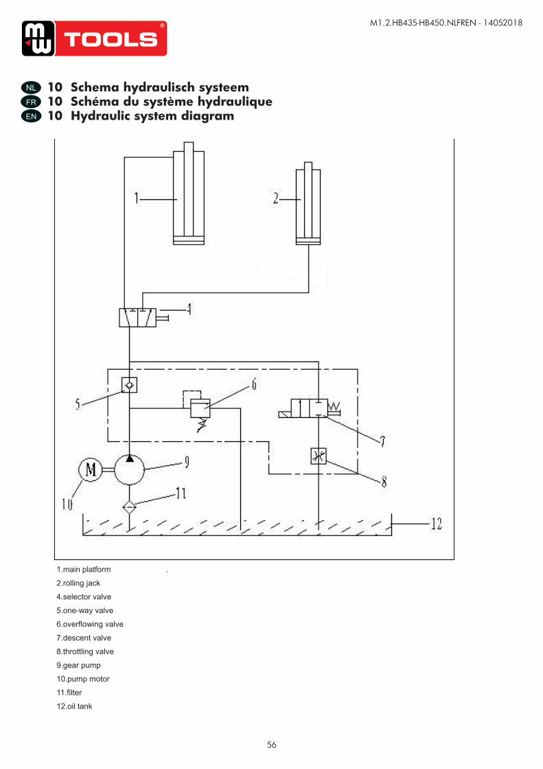
56
M1.2.HB435-HB450.NLFREN - 14052018
NL
FR
EN
10 Schema hydraulisch systeem10 Schéma du système hydraulique10 Hydraulic system diagram
UUSSEERR’’SS MMAANNUUAALL VV11..11 220011550099
- 22 -
11. Hydraulic pressure elements diagram
1.main platform .
2.rolling jack
4.selector valve
5.one-way valve
6.overflowing valve
7.descent valve
8.throttling valve
9.gear pump
10.pump motor
11.filter
12.oil tank
copy
righte
d do
cume
nt - a
ll rig
hts re
serv
ed b
y FB
C
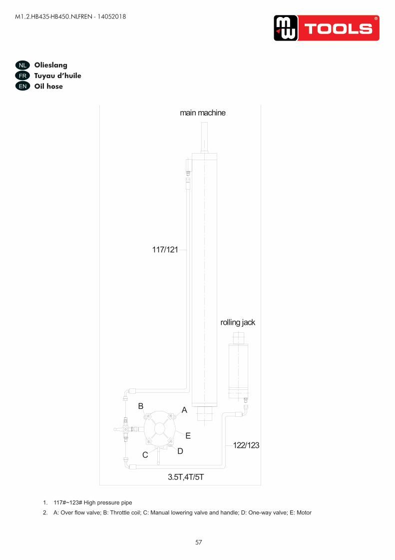
57
M1.2.HB435-HB450.NLFREN - 14052018
NL
FR
EN
OlieslangTuyau d’huileOil hose
UUSSEERR’’SS MMAANNUUAALL VV11..11 220011550099
- 23 -
12. Oil hose connection diagram
1. 117#~123# High pressure pipe
2. A: Over flow valve; B: Throttle coil; C: Manual lowering valve and handle; D: One-way valve; E: Motor
A
C D
B
main machine
117/121
E
rolling jack
122/123
3.5T,4T/5T
copy
righte
d do
cume
nt - a
ll rig
hts re
serv
ed b
y FB
C
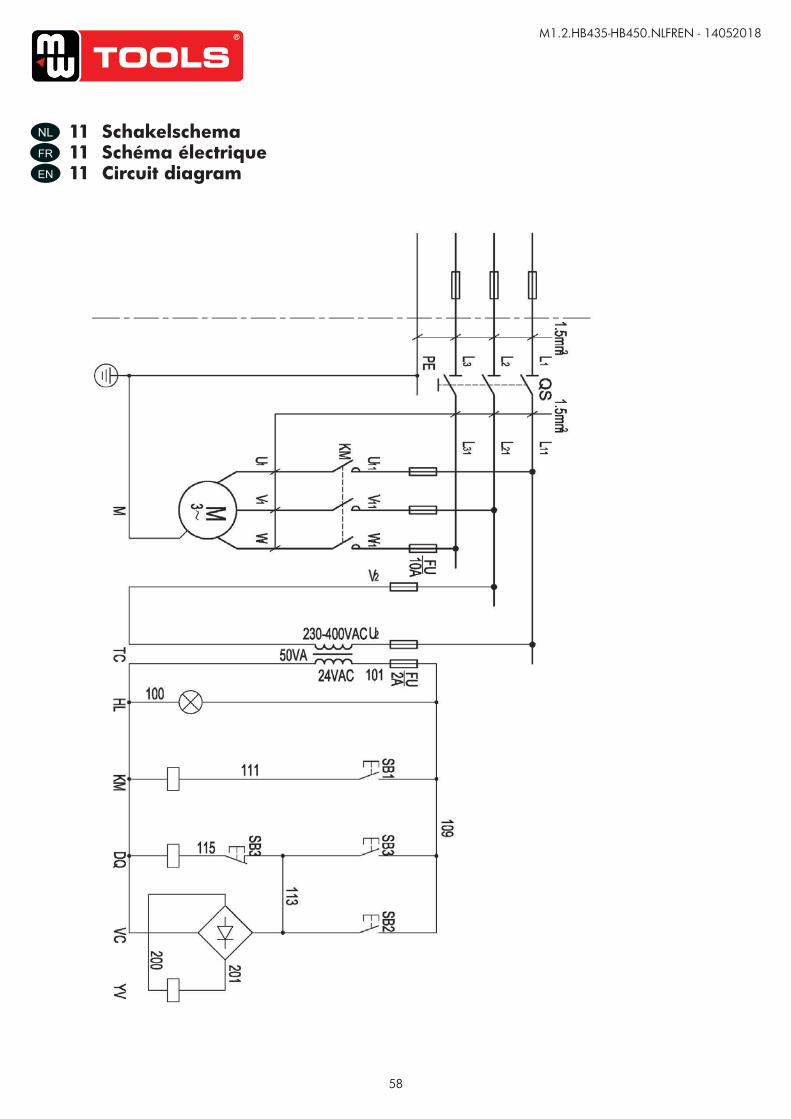
58
M1.2.HB435-HB450.NLFREN - 14052018
NL
FR
EN
11 Schakelschema11 Schéma électrique11 Circuit diagram
UUSSEERR’’SS MMAANNUUAALL VV11..11 220011550099
- 24 -
13. Circuit drawing
14.Explosion drawing
copy
righte
d do
cume
nt - a
ll rig
hts re
serv
ed b
y FB
C
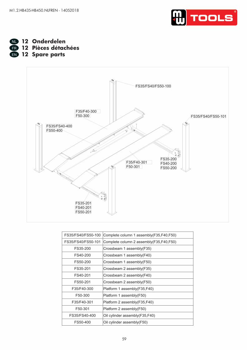
59
M1.2.HB435-HB450.NLFREN - 14052018
NL
FR
EN
12 Onderdelen12 Pièces détachées12 Spare parts UUSSEERR’’SS MMAANNUUAALL VV11..11 220011550099
- 25 -
FS35/FS40/FS50-100 Complete column 1 assembly(F35,F40,F50)
FS35/FS40/FS50-101 Complete column 2 assembly(F35,F40,F50)
FS35-200 Crossbeam 1 assembly(F35)
FS40-200 Crossbeam 1 assembly(F40)
FS50-200 Crossbeam 1 assembly(F50)
FS35-201 Crossbeam 2 assembly(F35)
FS40-201 Crossbeam 2 assembly(F40)
FS50-201 Crossbeam 2 assembly(F50)
F35/F40-300 Platform 1 assembly(F35,F40)
F50-300 Platform 1 assembly(F50)
F35/F40-301 Platform 2 assembly(F35,F40)
F50-301 Platform 2 assembly(F50)
FS35/FS40-400 Oil cylinder assembly(F35,F40)
FS50-400 Oil cylinder assembly(F50)
FS35/FS40/FS50-100
FS35/FS40/FS50-101
FS35-200FS40-200FS50-200
F35/F40-301F50-301
FS35-201FS40-201FS50-201
FS35/FS40-400FS50-400
F35/F40-300F50-300
copy
righte
d do
cume
nt - a
ll rig
hts re
serv
ed b
y FB
C
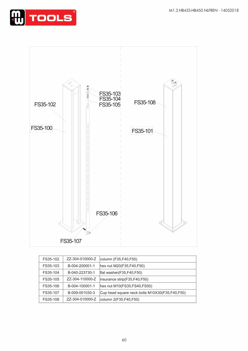
60
M1.2.HB435-HB450.NLFREN - 14052018
UUSSEERR’’SS MMAANNUUAALL VV11..11 220011550099
- 26 -
FS35-100
FS35-102 FS35-105
FS35-106
FS35-107
FS35-108
FS35-101
FS35-104FS35-103
FS35-102 ZZ-304-010000-Z column (F35,F40,F50)
FS35-103 B-004-200001-1 hex nut M20(F35,F40,F50)
FS35-104 B-040-223730-1 flat washer(F35,F40,F50)
FS35-105 ZZ-304-110000-Z insurance strip(F35,F40,F50)
FS35-106 B-004-100001-1 hex nut M10(FS35,FS40,FS50)
FS35-107 B-009-001030-3 Cup head square neck bolts M10X30(F35,F40,F50)
FS35-108 ZZ-304-010000-Z column 2(F35,F40,F50)
copy
righte
d do
cume
nt - a
ll rig
hts re
serv
ed b
y FB
C
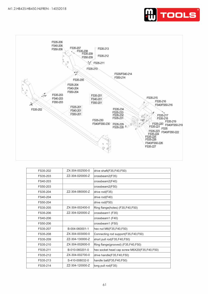
61
M1.2.HB435-HB450.NLFREN - 14052018
UUSSEERR’’SS MMAANNUUAALL VV11..11 220011550099
- 27 -
FS35-202 ZX-304-002500-0 drive shaft(F35,F40,F50)
FS35-203 ZZ-304-020000-Z crossbeam2(F35)
FS40-203 crossbeam2(F40)
FS50-203 crossbeam2(F50)
FS35-204 ZZ-304-080000-Z drive rod(F35)
FS40-204 drive rod(F40)
FS50-204 drive rod(F50)
FS35-205 ZX-304-002400-0 Ring flange(holes) (F35,F40,F50)
FS35-206 ZZ-304-020000-Z crossbeam1 (F35)
FS40-206 crossbeam1 (F40)
FS50-206 crossbeam1 (F50)
FS35-207 B-004-060001-1 hex nut M6(F35,F40,F50)
FS35-208 ZX-304-003000-0 Connecting rod support(F35,F40,F50)
FS35-209 ZZ-304-130000-Z short pull rod(F35,F40,F50)
FS35-210 ZX-304-002600-0 Ring flange(grooved) (F35,F40,F50)
FS35-211 B-010-060201-0 hex socket head cap screw M6X20(F35,F40,F50)
FS35-212 ZX-304-002700-0 drive handle(F35,F40,F50)
FS35-213 S-410-008032-0 handle ball(F35,F40,F50)
FS35-214 ZZ-304-120000-Z long pull rod(F35)
FS35-201FS40-201FS50-201
FS35-207FS35-208
FS35-209FS50-209
FS35-211
FS35-212
FS35-213
FS35-210
FS35/FS40-214FS50-214
FS35-215FS35-216FS40/FS50-216
FS35-217FS35-218
FS35-219FS40/FS50-219FS35-220
FS35FS40/FS50-222FS35-223
FS35-221
FS35-224FS35-225FS35-226FS40/FS50-226FS35-227
FS35-228FS35-229
FS35-230FS40/FS50-230
FS35-231FS35-232FS35-233FS35-234
FS35-205
FS35-203FS40-203FS50-203
FS35-202
FS35-201FS40-201FS50-201
FS35-204FS40-204FS50-204
FS35-206FS40-206FS50-206
copy
righte
d do
cume
nt - a
ll rig
hts re
serv
ed b
y FB
C
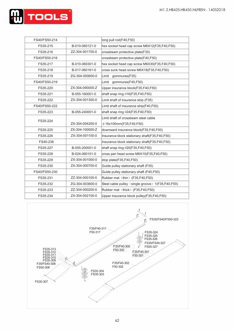
62
M1.2.HB435-HB450.NLFREN - 14052018
UUSSEERR’’SS MMAANNUUAALL VV11..11 220011550099
- 28 -
FS40/FS50-214 long pull rod(F40,F50)
FS35-215 B-010-060121-0 hex socket head cap screw M6X12(F35,F40,F50)
FS35-216 ZZ-304-001700-0 crossbeam protective plate(F35)
FS40/FS50-216 crossbeam protective plate(F40,F50)
FS35-217 B-010-060301-0 hex socket head cap screw M6X30(F35,F40,F50)
FS35-218 B-017-060161-0 cross sunk head screw M6X18(F35,F40,F50)
FS35-219 ZG-304-000600-0 Limit gommures(F35)
FS40/FS50-219 Limit gommures(F40,F50)
FS35-220 ZX-304-090000-Z Upper insurance block(F35,F40,F50)
FS35-221 B-055-160001-0 shaft snap ring Ø16(F35,F40,F50)
FS35-222 ZX-304-001300-0 Limit shaft of insurance strip (F35)
FS40/FS50-222 Limit shaft of insurance strip(F40,F50)
FS35-223 B-055-240001-0 shaft snap ring Ø24(F35,F40,F50)
FS35-224 ZX-304-004200-0
Limit shaft of crossbeam steel cable
φ16x100mm(F35,F40,F50)
FS35-225 ZX-304-100000-Z downward insurance block(F35,F40,F50)
FS35-226 ZX-304-001100-0 Insurance block stationary shaft(F35,F40,F50)
FS40-236 Insurance block stationary shaft(F35,F40,F50)
FS35-227 B-055-200001-0 shaft snap ring Ø20(F35,F40,F50)
FS35-228 B-024-060101-0 cross pan head screw M6X10(F35,F40,F50)
FS35-229 ZX-304-001000-0 stop plate(F35,F40,F50)
FS35-230 ZX-304-000700-0 Guide pulley stationary shaft (F35)
FS40/FS50-230 Guide pulley stationary shaft (F40,F50)
FS35-231 ZZ-304-000100-0 Rubber mat(thin)(F35,F40,F50)
FS35-232 ZG-304-003600-0 Steel cable pulley(single groove)1(F35,F40,F50)
FS35-233 ZZ-304-000200-0 Rubber mat(thick)(F35,F40,F50)
FS35-234 ZX-304-002100-0 Upper insurance block pulley(F35,F40,F50)
FS35-303FS35-304
FS35-307
F35/FS40-308FS50-308
FS35-309FS35-310FS35-311FS35-312FS35-313
FS35/FS40/FS50-323
FS35-324FS35-325FS35-326FS35/FS40-327FS50-327F35/F40-300
F50-300 F35/F40-301F50-301
F35/F40-302F50-302
F35/F40-317F50-317
copy
righte
d do
cume
nt - a
ll rig
hts re
serv
ed b
y FB
C
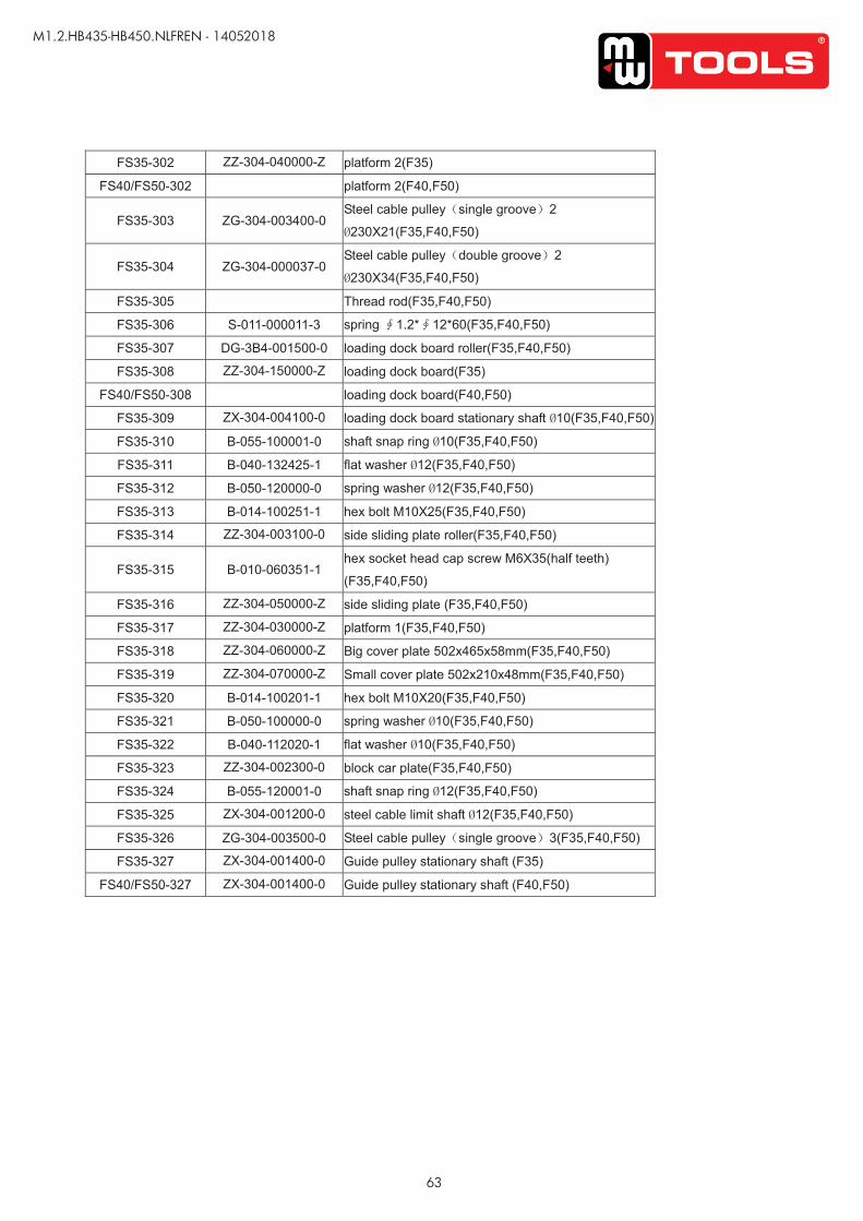
63
M1.2.HB435-HB450.NLFREN - 14052018
UUSSEERR’’SS MMAANNUUAALL VV11..11 220011550099
- 29 -
FS35-302 ZZ-304-040000-Z platform 2(F35)
FS40/FS50-302 platform 2(F40,F50)
FS35-303 ZG-304-003400-0 Steel cable pulley(single groove)2
Ø230X21(F35,F40,F50)
FS35-304 ZG-304-000037-0 Steel cable pulley(double groove)2
Ø230X34(F35,F40,F50)
FS35-305 Thread rod(F35,F40,F50)
FS35-306 S-011-000011-3 spring ∮1.2*∮12*60(F35,F40,F50)
FS35-307 DG-3B4-001500-0 loading dock board roller(F35,F40,F50)
FS35-308 ZZ-304-150000-Z loading dock board(F35)
FS40/FS50-308 loading dock board(F40,F50)
FS35-309 ZX-304-004100-0 loading dock board stationary shaft Ø10(F35,F40,F50)
FS35-310 B-055-100001-0 shaft snap ring Ø10(F35,F40,F50)
FS35-311 B-040-132425-1 flat washer Ø12(F35,F40,F50)
FS35-312 B-050-120000-0 spring washer Ø12(F35,F40,F50)
FS35-313 B-014-100251-1 hex bolt M10X25(F35,F40,F50)
FS35-314 ZZ-304-003100-0 side sliding plate roller(F35,F40,F50)
FS35-315 B-010-060351-1 hex socket head cap screw M6X35(half teeth)
(F35,F40,F50)
FS35-316 ZZ-304-050000-Z side sliding plate (F35,F40,F50)
FS35-317 ZZ-304-030000-Z platform 1(F35,F40,F50)
FS35-318 ZZ-304-060000-Z Big cover plate 502x465x58mm(F35,F40,F50)
FS35-319 ZZ-304-070000-Z Small cover plate 502x210x48mm(F35,F40,F50)
FS35-320 B-014-100201-1 hex bolt M10X20(F35,F40,F50)
FS35-321 B-050-100000-0 spring washer Ø10(F35,F40,F50)
FS35-322 B-040-112020-1 flat washer Ø10(F35,F40,F50)
FS35-323 ZZ-304-002300-0 block car plate(F35,F40,F50)
FS35-324 B-055-120001-0 shaft snap ring Ø12(F35,F40,F50)
FS35-325 ZX-304-001200-0 steel cable limit shaft Ø12(F35,F40,F50)
FS35-326 ZG-304-003500-0 Steel cable pulley(single groove)3(F35,F40,F50)
FS35-327 ZX-304-001400-0 Guide pulley stationary shaft (F35)
FS40/FS50-327 ZX-304-001400-0 Guide pulley stationary shaft (F40,F50)
copy
righte
d do
cume
nt - a
ll rig
hts re
serv
ed b
y FB
C
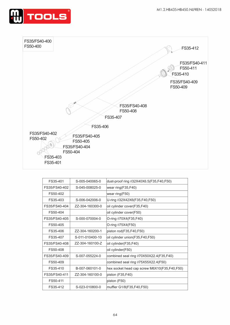
64
M1.2.HB435-HB450.NLFREN - 14052018
UUSSEERR’’SS MMAANNUUAALL VV11..11 220011550099
- 30 -
FS35-401 S-005-040065-0 dust-proof ring Ø32X40X6.5(F35,F40,F50)
FS35/FS40-402 S-045-008025-0 wear ring(F35,F40)
FS50-402 wear ring(F50)
FS35-403 S-006-042006-0 U-ring Ø32X42X6(F35,F40,F50)
FS35/FS40-404 ZZ-304-160300-0 oil cylinder cover(F35,F40)
FS50-404 oil cylinder cover(F50)
FS35/FS40-405 S-000-070004-0 O-ring Ø70X4(F35,F40)
FS50-405 O-ring Ø75X4(F50)
FS35-406 ZZ-304-160200-1 piston rod(F35,F40,F50)
FS35-407 S-011-010400-10 oil cylinder union(F35,F40,F50)
FS35/FS40-408 ZZ-304-160100-Z oil cylinder(F35,F40)
FS50-408 oil cylinder(F50)
FS35/FS40-409 S-007-055224-0 combined seal ring Ø70X50X22.4(F35,F40)
FS50-409 combined seal ring Ø75X55X22.4(F50)
FS35-410 B-007-060101-0 hex socket head cap screw M6X10(F35,F40,F50)
FS35/FS40-411 ZZ-304-160100-0 piston (F35,F40)
FS50-411 piston (F50)
FS35-412 S-023-010800-0 muffler G1/8(F35,F40,F50)
FS35/FS40-400FS50-400
FS35-401FS35-403
FS35/FS40-402FS50-402
FS35/FS40-404FS50-404
FS35/FS40-405FS50-405
FS35-406
FS35-407
FS35/FS40-409FS50-409
FS35/FS40-408FS50-408
FS35-410
FS35/FS40-411FS50-411
FS35-412co
pyrig
hted
docu
ment
- all r
ights
rese
rved
by
FBC
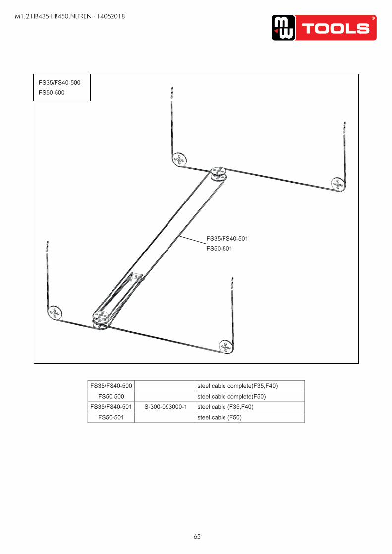
65
M1.2.HB435-HB450.NLFREN - 14052018
UUSSEERR’’SS MMAANNUUAALL VV11..11 220011550099
- 31 -
FS35/FS40-500 steel cable complete(F35,F40)
FS50-500 steel cable complete(F50)
FS35/FS40-501 S-300-093000-1 steel cable (F35,F40)
FS50-501 steel cable (F50)
FS35/FS40-500
FS50-500
FS35/FS40-501
FS50-501
copy
righte
d do
cume
nt - a
ll rig
hts re
serv
ed b
y FB
C
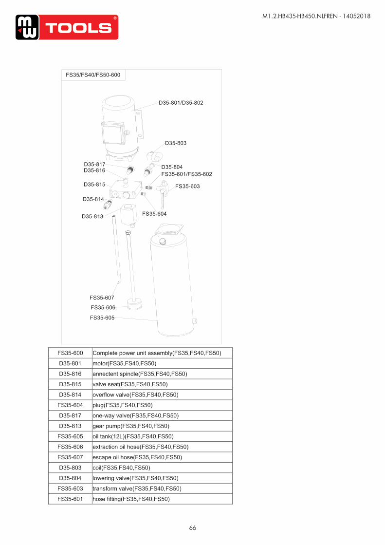
66
M1.2.HB435-HB450.NLFREN - 14052018
UUSSEERR’’SS MMAANNUUAALL VV11..11 220011550099
- 32 -
FS35-600 Complete power unit assembly(FS35,FS40,FS50)
D35-801 motor(FS35,FS40,FS50)
D35-816 annectent spindle(FS35,FS40,FS50)
D35-815 valve seat(FS35,FS40,FS50)
D35-814 overflow valve(FS35,FS40,FS50)
FS35-604 plug(FS35,FS40,FS50)
D35-817 one-way valve(FS35,FS40,FS50)
D35-813 gear pump(FS35,FS40,FS50)
FS35-605 oil tank(12L)(FS35,FS40,FS50)
FS35-606 extraction oil hose(FS35,FS40,FS50)
FS35-607 escape oil hose(FS35,FS40,FS50)
D35-803 coil(FS35,FS40,FS50)
D35-804 lowering valve(FS35,FS40,FS50)
FS35-603 transform valve(FS35,FS40,FS50)
FS35-601 hose fitting(FS35,FS40,FS50)
FS35/FS40/FS50-600
D35-801/D35-802
D35-803
D35-804
D35-813
D35-814
D35-815
D35-817D35-816
FS35-605
FS35-606
FS35-607
FS35-601/FS35-602
FS35-603
FS35-604
copy
righte
d do
cume
nt - a
ll rig
hts re
serv
ed b
y FB
C
67
M1.2.HB435-HB450.NLFREN - 14052018
Fabrikant/Invoerder Fabricant/ImportateurManufacturer/Retailer
Verklaart hierbij dat het volgende product :Déclare par la présente que le produit suivant :Hereby declares that the following product :
ProductProduitProduct
Hefbrug 4 kolommenPont élévateur à 4 colonnes4-post hydraulic lift
Order nr. :
Geldende CE-richtlijnenNormes CE en vigueurRelevant EU directives
2006/42/EC2014/30/EUEN ISO 12100:2010EN 1493:2010EN 1494:2000+A1:2008EN 60204-1:2006+A1:2009EN 61000-6-2:2005EN 61000-6-4:2007/A1:2011
Overeenstemt met de bestemming van de hierboven aangeduide richtlijnen - met inbegrip van deze betreffende het tijdstip van de verklaring der geldende veranderingen.Répond aux normes générales caractérisées plus haut, y compris celles dont la date correspond aux modifications en vigueur.Meets the provisions of the aforementioned directive, including, any amendments valid at the time of this statement.
Test report reference: CE-C-0407-11-17-01-5B
Vynckier Tools nv/saAvenue Patrick Wagnonlaan, 7 ZAEM de HaureuB-7700 Mouscron - Moeskroen
13 EG conformiteitsverklaring13 Déclaration de conformité CE13 EC declaration of conformity
HB435 (724563062)
HB450 (724563066)
FR
EN
NL
Bart Vynckier, Director VYNCKIER TOOLS nv/sa
Moeskroen/Mouscron, 14/05/2018
copy
righte
d do
cume
nt - a
ll rig
hts re
serv
ed b
y FB
C