Embed Size (px)
Citation preview
Hochbitratige optische Übertragungssysteme
Empfänger
C.-A. Bunge; Hochschule für Telekommunikation Leipzig: High-Speed Optical Transmission Systems
Taktrück-gewinnung
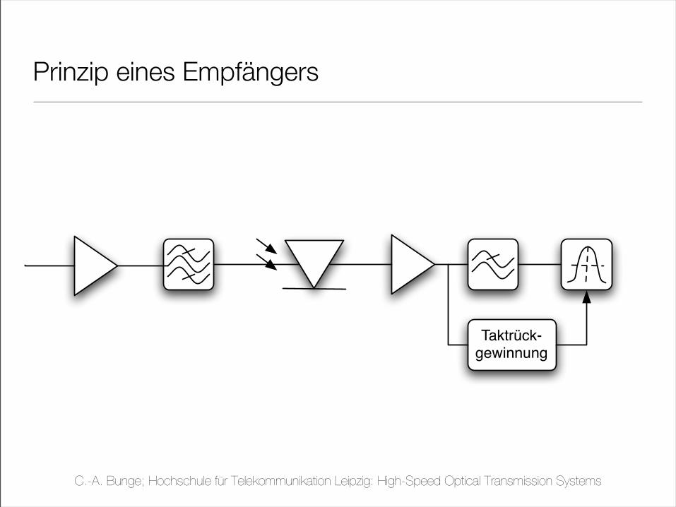
Prinzip eines Empfängers
C.-A. Bunge; Hochschule für Telekommunikation Leipzig: High-Speed Optical Transmission Systems
Taktrück-gewinnung
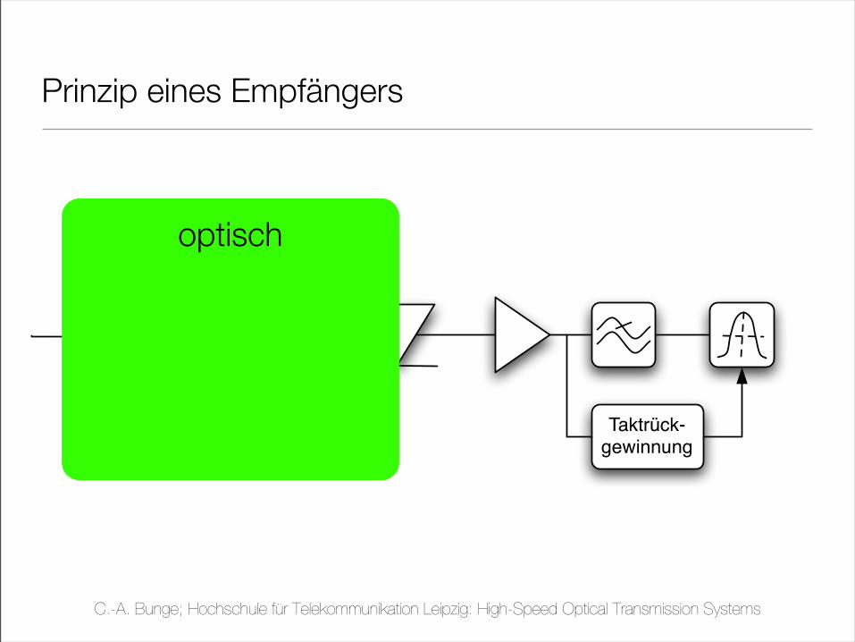
Prinzip eines Empfängers
optisch
C.-A. Bunge; Hochschule für Telekommunikation Leipzig: High-Speed Optical Transmission Systems
Taktrück-gewinnung
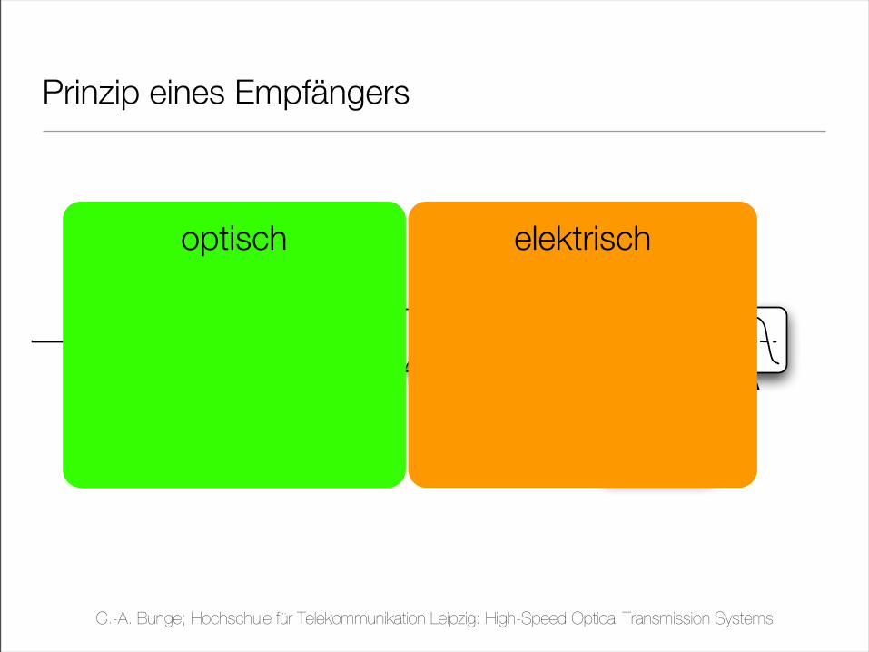
Prinzip eines Empfängers
optisch elektrisch
C.-A. Bunge; Hochschule für Telekommunikation Leipzig: High-Speed Optical Transmission Systems
Taktrück-gewinnung
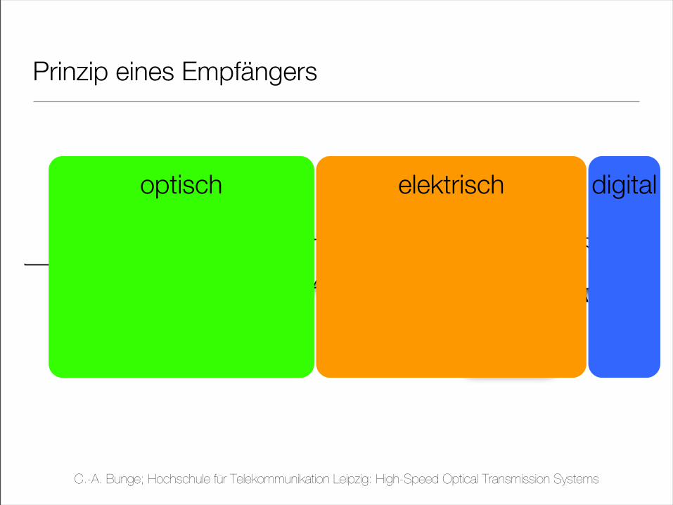
Prinzip eines Empfängers
optisch elektrisch digital
C.-A. Bunge; Hochschule für Telekommunikation Leipzig: High-Speed Optical Transmission Systems
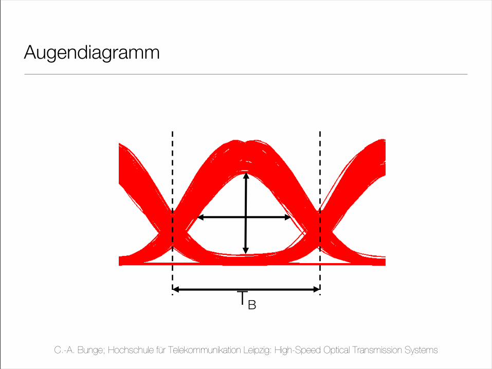
Augendiagramm
TB
C.-A. Bunge; Hochschule für Telekommunikation Leipzig: High-Speed Optical Transmission Systems
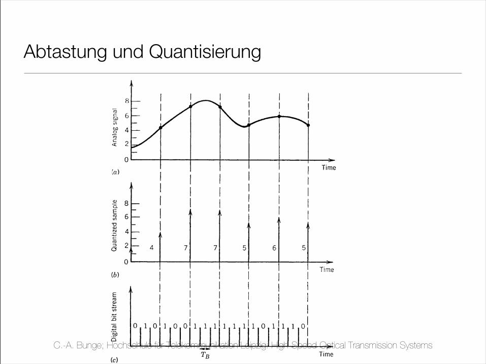
Abtastung und Quantisierung
C.-A. Bunge; Hochschule für Telekommunikation Leipzig: High-Speed Optical Transmission Systems

zur Taktrückgewinnung...
C.-A. Bunge; Hochschule für Telekommunikation Leipzig: High-Speed Optical Transmission Systems
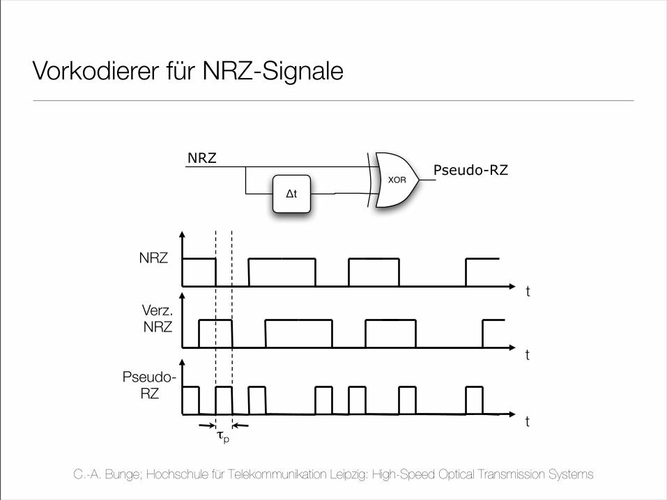
!t
XOR
NRZPseudo-RZ
Vorkodierer für NRZ-Signale
NRZ
Verz.NRZ
Pseudo-RZ
t
t
tτp
C.-A. Bunge; Hochschule für Telekommunikation Leipzig: High-Speed Optical Transmission Systems
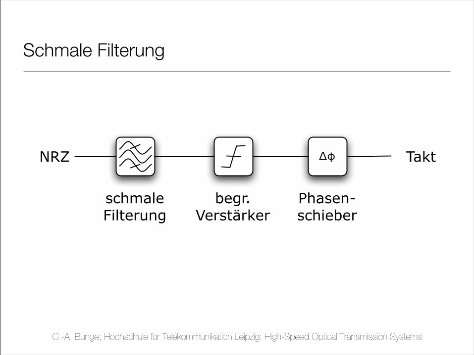
NRZ !" Takt
Phasen-schieber
begr.Verstärker
schmaleFilterung
Schmale Filterung
C.-A. Bunge; Hochschule für Telekommunikation Leipzig: High-Speed Optical Transmission Systems
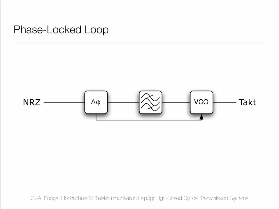
NRZ !" TaktVCO
Phase-Locked Loop
C.-A. Bunge; Hochschule für Telekommunikation Leipzig: High-Speed Optical Transmission Systems
!"!##$%&'()*+,-'#../&'0-123'43'53'%678,*+9:6 ;,<+7-,'=&'>6)?,'=.
>)@*:6'+1'A1)B,'C:+)1'D>ACE
;:B,-'
F-:*B8)++,-
F-:*B8)++,-'A1)B,
C,6:+)G,'H*+,*B)+I'A1)B,'DCHAE
+
09:B,
*1)B,
!
J1?,
K:-+)+)1*
*1)B,
DJ0AE
!
!4LM
NK+)<:6'M8K6)!,-'A1)B,
>)@*:6O>K1*+:*,17B'A1)B,
>K1*+:*,17BO>K1*+:*,17B'A1)B,
C,<,)G,-
C,<,)G,-'A1)B,
>91+'*1)B,&'M04'*1)B,
F9,-8:6'*1)B,
M8K6)!,-'*1)B,
"61<P'5)++,-
+ + +
4)BK,-B)G,'"9:**,6'A1)B,
J1?,'0:-+)+)1*'A1)B,'DJ0AE
4)BK,-B)1*')*?7<,?'Q)++,-
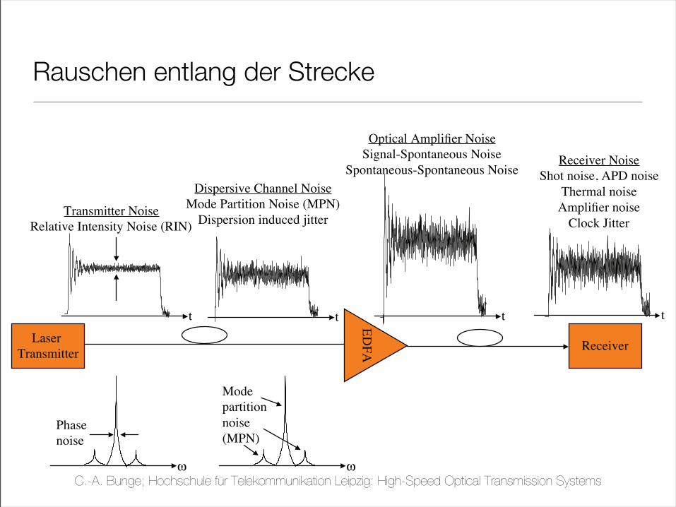
Rauschen entlang der Strecke
C.-A. Bunge; Hochschule für Telekommunikation Leipzig: High-Speed Optical Transmission Systems
ECE228B, Winter 2006, Prof. D. J. Blumenthal Lecture 2, Slide 3
Electrical Signal-to-Noise Ratio (SNR)
! At the receiver, there is noise on the signal arriving at the input and and after detection
added to that is noise that is injected at various stages of the receiver
! The current output of the receiver in(t) has current contributions from
! Electrical shot noise
! Thermal noise
! APD detectors have additional multiplication noise
! Amplifier noise
Receiver
I(t) = Ip(t) + in(t)
2!1
2!0
Popt(t) = PSig(t) + Pn(t)
t
<I1>
<I0>
Det
ecto
r O
utp
ut
Curr
ent
(I)
photodetector
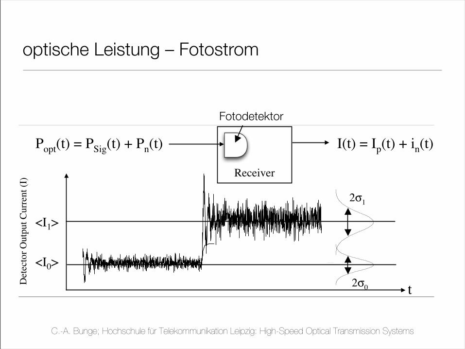
optische Leistung – Fotostrom
Fotodetektor
C.-A. Bunge; Hochschule für Telekommunikation Leipzig: High-Speed Optical Transmission Systems
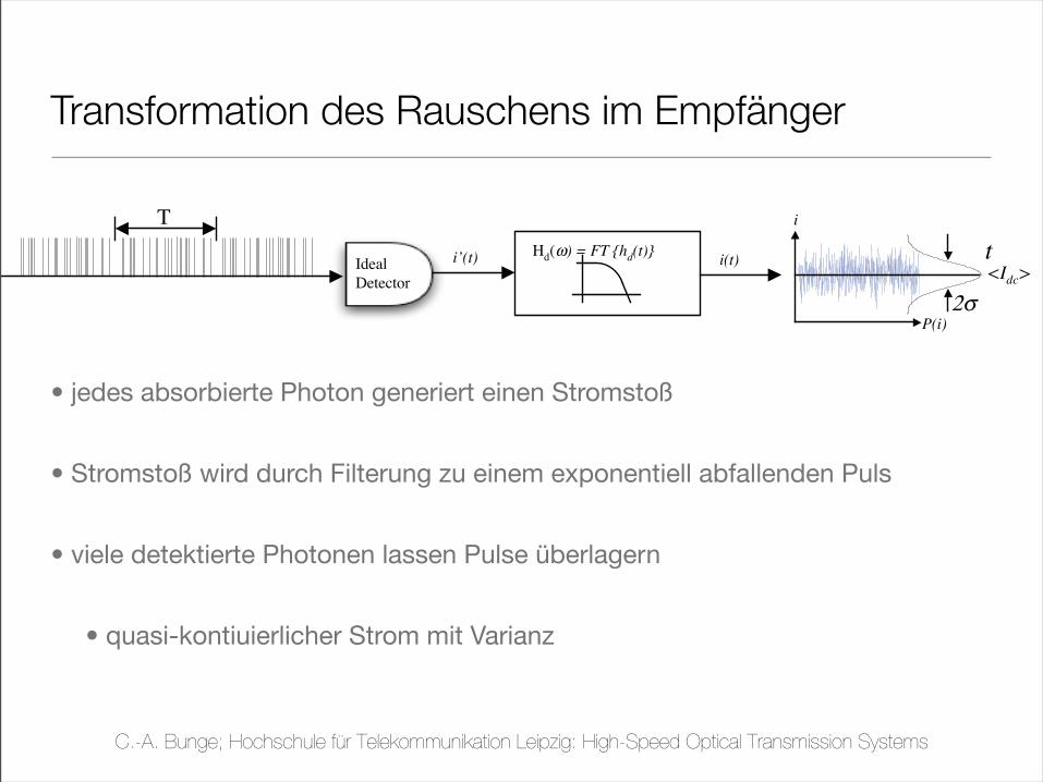
Transformation des Rauschens im Empfänger
• jedes absorbierte Photon generiert einen Stromstoß
• Stromstoß wird durch Filterung zu einem exponentiell abfallenden Puls
• viele detektierte Photonen lassen Pulse überlagern
• quasi-kontiuierlicher Strom mit Varianz
!"!##$%&'()*+,-'#../&'0-123'43'53'%678,*+9:6 ;,<+7-,'=&'>6)?,'#@
4,+,<+)*A'091+1*B'CDE
! FB'+9,':G,-:A,'H91+1*'-:+,')*<-,:B,B&'+9,'1IB,-G,?'H91+1J<7--,*+'B+:-+B'B811+9)*A
17+&'K)+9':'G:-):*<,':-17*?'+9,'8,:*'C:G,-:A,E'<17*+'+9:+')B'I:B,?'1*'+9,'B+:+)B+)<B
CK9)<9'+,*?B'+1'L:7BB):*''21-'6:-A,'H91+1*':--)G:6'-:+,E
! !"#$')B'+9,'H-1I:I)6)+M'27*<+)1*'12'8,:B7-)*A'+9,'<7--,*+':+':'<,-+:)*'G:67,':+'+)8,'+3
%
#
!!
&'()*N?,:6
4,+,<+1-
#+"%$ O?C"$,-,./,01("%$2 #"%$
P
!"#$
C.-A. Bunge; Hochschule für Telekommunikation Leipzig: High-Speed Optical Transmission Systems
!"!##$%&'()*+,-'#../&'0-123'43'53'%678,*+9:6 ;,<+7-,'=&'>6)?,'#@
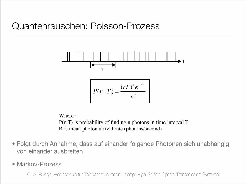
091+1*'>+:+)A+)<A
! 091+1*'A17-<,A'<:*')*'B,*,-:6'C,'<9:-:<+,-)D,?':A'<19,-,*+'1-')*<19,-,*+E
! "19,-,*+F'0-1C:C)6)+G'+9:+':'H91+1*')A'B,*,-:+,?':+'+)8,'+.')A'87+7:66G')*?,H,*?,*+'12
H-1C:C)6)+G'12'H91+1*A'B,*,-:+,?':+'1+9,-'+)8,A'IJ:-K1L'0-1<,AAM
! 01)AA1*'0-1<,AAF'0-1C:C)6)+G'12'!*?)*B'!'H91+1*A')*'+)8,')*+,-L:6'"
! %7*<9)*B')A':'+-:)+'12'+9,'01)AA1*'H-1<,AA
! N*+,-:--)L:6'+)8,')A'?,<:G)*B',OH1*,*+):66G'?)A+-)C7+,?
!!" "# # !!$# #
"%!$#
"$
+
P
(9,-,'F
0I*QPM')A'H-1C:C)6)+G'12'!*?)*B'*'H91+1*A')*'+)8,')*+,-L:6'P
R')A'8,:*'H91+1*':--)L:6'-:+,'IH91+1*ASA,<1*?M
E'":*':6A1'C,':
<18C)*:+)1*'12'+9,A,
+T1'+GH,A'UV'H:-+):66G
<19,-,*+
Quantenrauschen: Poisson-Prozess
• Folgt durch Annahme, dass auf einander folgende Photonen sich unabhängig von einander ausbreiten
• Markov-Prozess
C.-A. Bunge; Hochschule für Telekommunikation Leipzig: High-Speed Optical Transmission Systems
ECE228B, Winter 2006, Prof. D. J. Blumenthal Lecture 2, Slide 4
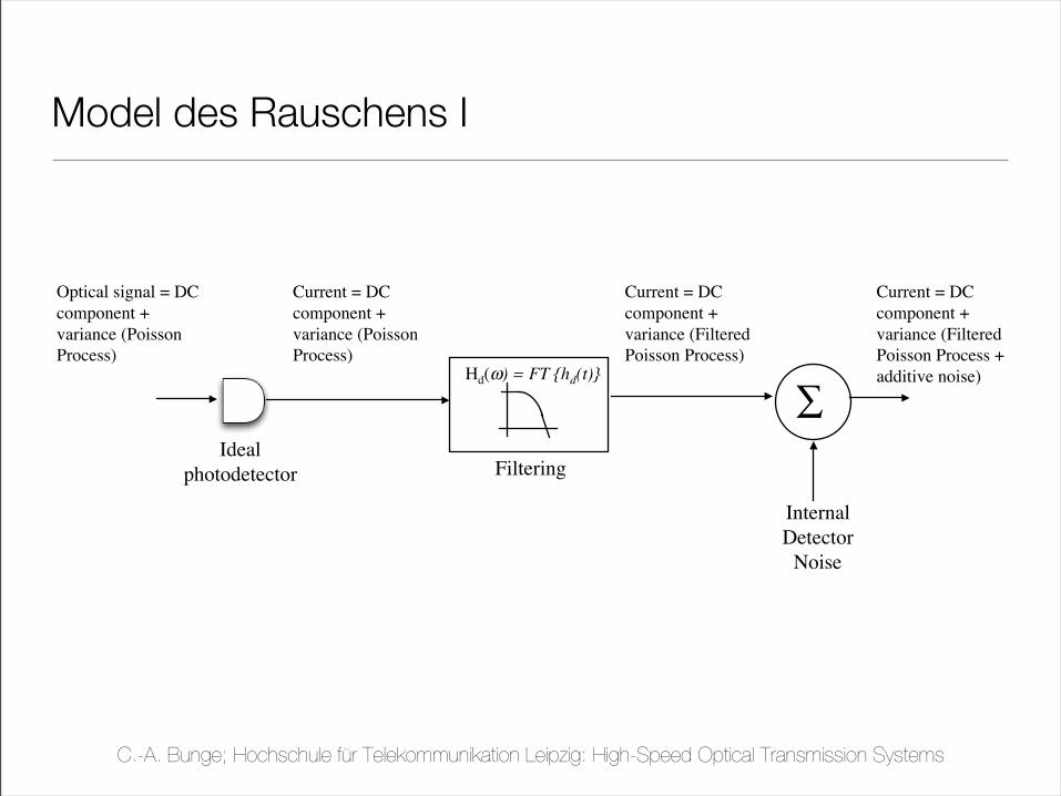
Modeling Detector SNR
! When observing the detector current output, it is difficult to tell which noise was
present at the optical input and which noise was generated internal to the detector.
So we tend to use several different models and combine them
Optical signal = DC
component +
variance (Poisson
Process)
Ideal
photodetector
Hd(!) = FT {hd(t)}
Filtering
Current = DC
component +
variance (Poisson
Process)
Current = DC
component +
variance (Filtered
Poisson Process)
!
Internal
Detector
Noise
Current = DC
component +
variance (Filtered
Poisson Process +
additive noise)
Model des Rauschens I
C.-A. Bunge; Hochschule für Telekommunikation Leipzig: High-Speed Optical Transmission Systems
ECE228B, Winter 2006, Prof. D. J. Blumenthal Lecture 2, Slide 6
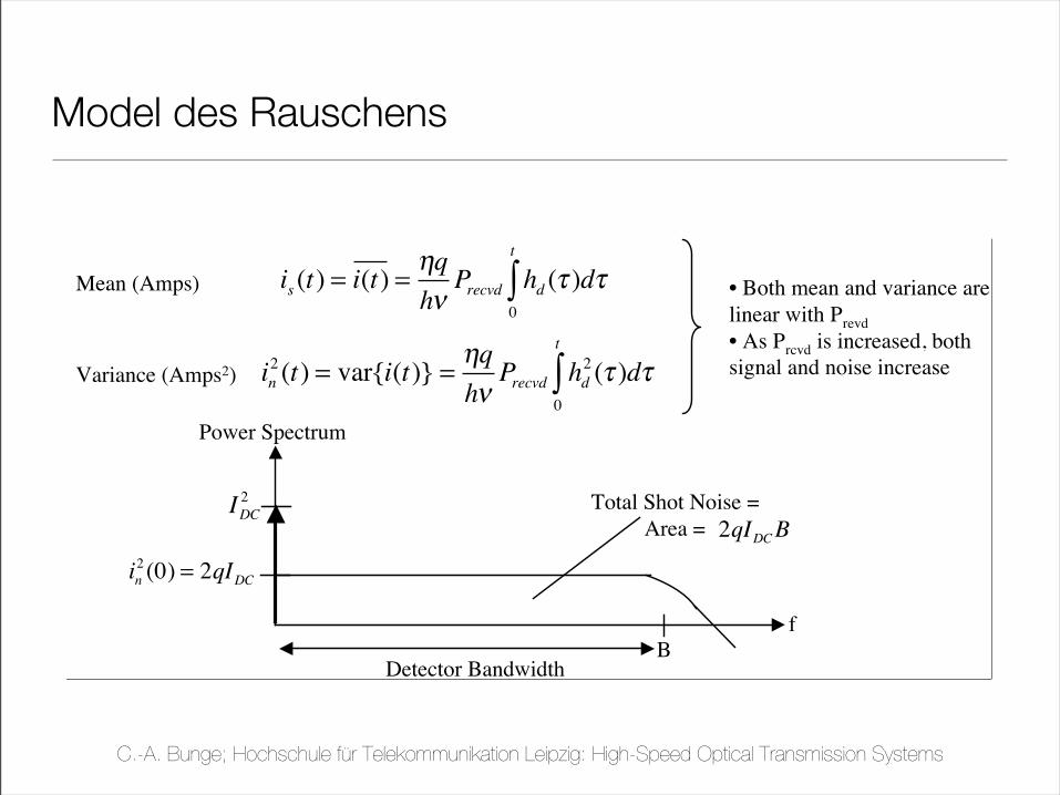
Shot Noise Mean and Variance
is (t) = i(t) =!q
h"Precvd hd (# )d#
0
t
$
in2(t) = var{i(t)} =
!q
h"Precvd hd
2(# )d#
0
t
$
! For constant power illumination, the rate parameter is constant, and the signal is the mean
! The noise corresponds to the photocurrent variance
! For a filter, homogeneous Poisson process
Mean (Amps)
Variance (Amps2)
• Both mean and variance are
linear with Prevd
• As Prcvd is increased, both
signal and noise increase
Power Spectrum
IDC
2
in2(0) = 2qIDC
B
f
Total Shot Noise =
Area = 2qIDCB
Detector Bandwidth
Model des Rauschens
C.-A. Bunge; Hochschule für Telekommunikation Leipzig: High-Speed Optical Transmission Systems
ECE228B, Winter 2006, Prof. D. J. Blumenthal Lecture 14, Slide 32
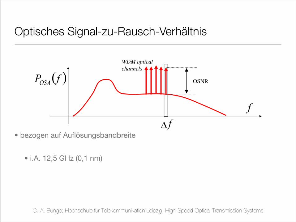
Optical Signal-to-Noise Ratio (OSNR)
! OSNR is an extremely important parameter in optically amplified systems
! A poor OSNR cannot in principle be improved at the receiver
! It is mainly determined by:
! Useful signal level
! ASE noise level
! OSNR is typically measured using an Optical Spectrum Analyzer (OSA)
! The resulting quantities are thus time averaged
! The OSNR is defined on a given resolution bandwidth !f (an example standardrequires 0.1 nm =12.5 GHz)
f
( )fPOSA
WDM optical
channels
OSNR
f!
Optisches Signal-zu-Rausch-Verhältnis
• bezogen auf Auflösungsbandbreite
• i.A. 12,5 GHz (0,1 nm)
C.-A. Bunge; Hochschule für Telekommunikation Leipzig: High-Speed Optical Transmission Systems
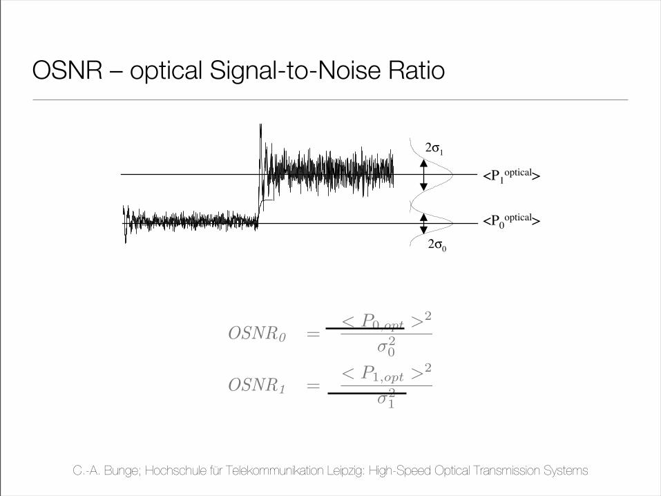
OSNR0 =< P0,opt >2
!20
OSNR1 =< P1,opt >2
!21
OSNR – optical Signal-to-Noise Ratio
ECE228B, Winter 2006, Prof. D. J. Blumenthal Lecture 14, Slide 31
Optical Signal-to-Noise Ratio (OSNR)
<P1optical>
<P0optical>
2!1
2!0
! Noise is accumulated in the optical channel due to
! RIN, MPN, Optical Amplifier Noise and Shot Noise.
! OSNR for each level and for complete signal can be defined
OSNR1=
P1
Optical 2
!1
2
OSNR0=
P0
Optical 2
!0
2
C.-A. Bunge; Hochschule für Telekommunikation Leipzig: High-Speed Optical Transmission Systems
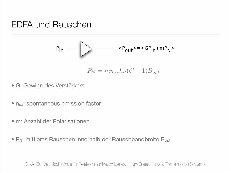
PN = mnsph!(G! 1)Bopt
EDFA und Rauschen
• G: Gewinn des Verstärkers
• nsp: spontaneous emission factor
• m: Anzahl der Polarisationen
• PN: mittleres Rauschen innerhalb der Rauschbandbreite Bopt
Pin
<Pout>=<GP
in+mP
N>
C.-A. Bunge; Hochschule für Telekommunikation Leipzig: High-Speed Optical Transmission Systems
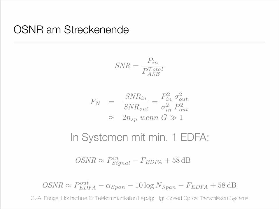
OSNR ! P inSignal " FEDFA + 58 dB
OSNR ! P outEDFA " !Span " 10 log NSpan " FEDFA + 58 dB
OSNR am Streckenende
SNR =Pin
PTotalASE
FN =SNRin
SNRout=
P 2in
!2in
!2out
P 2out
! 2nsp wenn G" 1
In Systemen mit min. 1 EDFA:
C.-A. Bunge; Hochschule für Telekommunikation Leipzig: High-Speed Optical Transmission Systems
ECE228B, Winter 2006, Prof. D. J. Blumenthal Lecture 14, Slide 45
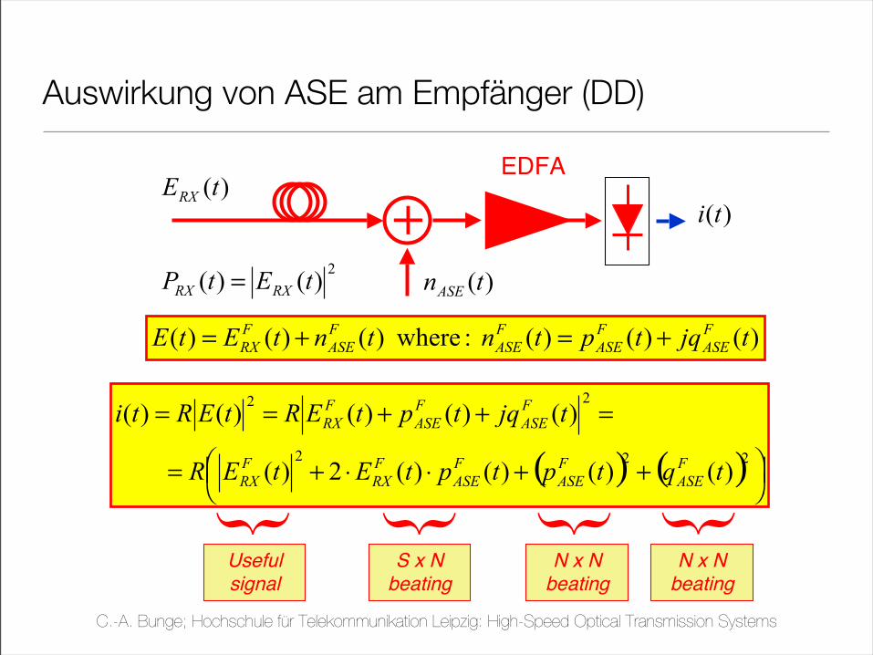
SNR due to Optical Amplifier ASE noise
! Effects of ASE noise (neglecting other noise sources)
)()()( : where)()()( tjqtptntntEtEF
ASE
F
ASE
F
ASE
F
ASE
F
RX +=+=
( ) ( ) !"#$
%& ++''+=
=++==
222
22
)()()()(2)(
)()()()()(
tqtptptEtER
tjqtptERtERti
F
ASE
F
ASE
F
ASE
F
RX
F
RX
F
ASE
F
ASE
F
RX
{
Usefulsignal
{
S x Nbeating
{N x N
beating
{
)(tnASE
+
)(tERX
2)()( tEtP
RXRX=
EDFA
)(ti
N x Nbeating
Auswirkung von ASE am Empfänger (DD)
C.-A. Bunge; Hochschule für Telekommunikation Leipzig: High-Speed Optical Transmission Systems
Signalqualität – Rauschen – Bitfehlerrate
C.-A. Bunge; Hochschule für Telekommunikation Leipzig: High-Speed Optical Transmission Systems
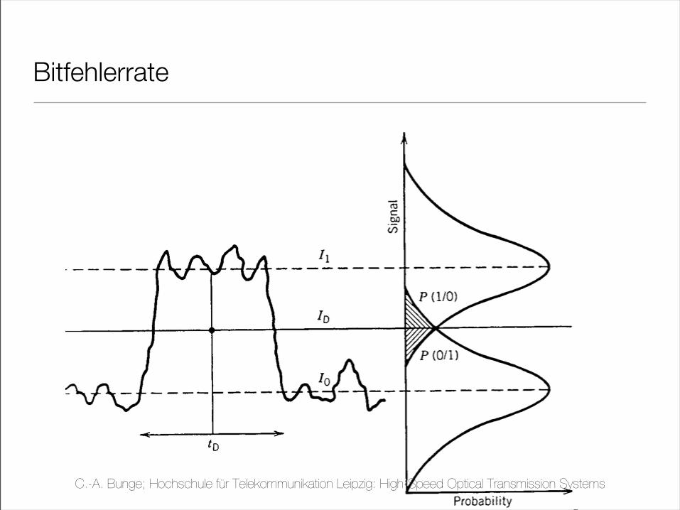
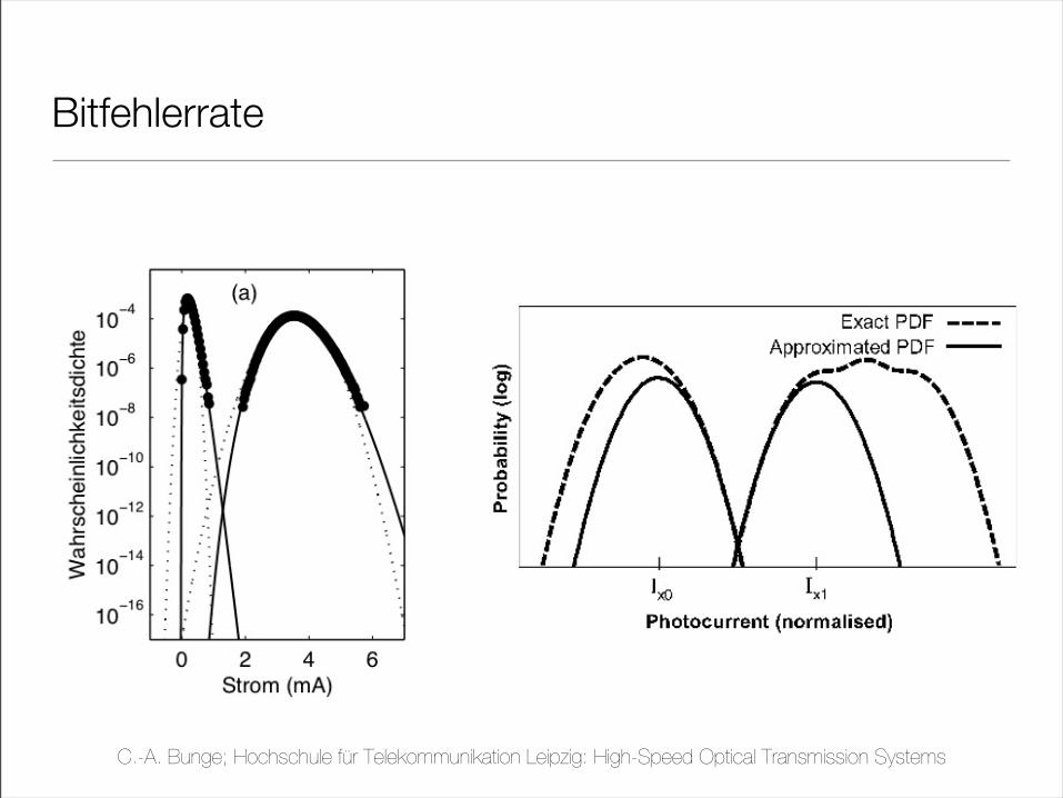
Bitfehlerrate
C.-A. Bunge; Hochschule für Telekommunikation Leipzig: High-Speed Optical Transmission Systems
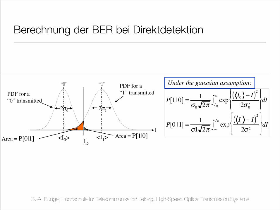
Berechnung der BER bei Direktdetektion
ECE228B, Winter 2006, Prof. D. J. Blumenthal Lecture 14, Slide 52
Bit Error Rate (BER)
!Probability of error = P[0]P[1|0] + P[1]P[0|1]
!P[0] = Probability a “0” was transmitted
!P[1] = Probability a “1” was transmitted
!P[1|0] = Probability a “1” is received given that a “0” is transmitted
!P[0|1] = Probability a “0” is received given that a “1” is transmitted
<I1><I0>
2!12!0
ID
PDF for a
“1” transmittedPDF for a
“0” transmitted
Area = P[0|1] Area = P[1|0]
“0” “1”
P 1| 0[ ] =1
!0 2"exp
I0 # I( )2
2! 02
$
% &
' &
(
) &
* & ID
+
, dI
P 0 | 1[ ] =1
!1 2"exp
I1 # I( )2
2!12
$
% &
' &
(
) &
* & +
ID
, dII
Under the gaussian assumption:
C.-A. Bunge; Hochschule für Telekommunikation Leipzig: High-Speed Optical Transmission Systems
ECE228B, Winter 2006, Prof. D. J. Blumenthal Lecture 14, Slide 53
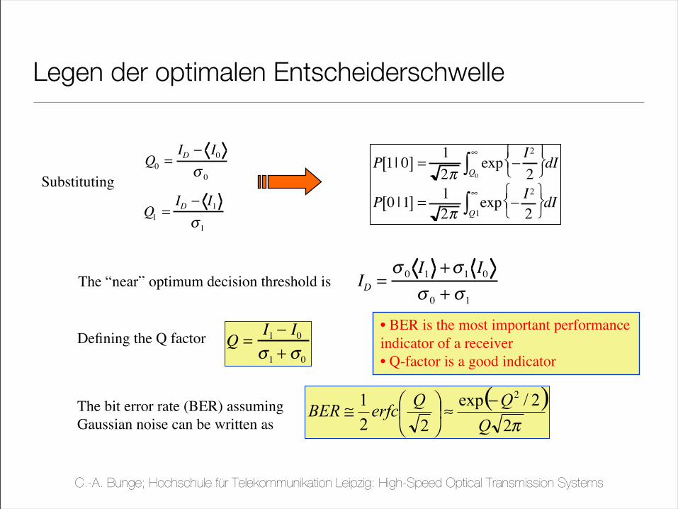
BER and Q-Factor
The “near” optimum decision threshold is ID=!0I1+!
1I0
!0+ !
1
The bit error rate (BER) assuming
Gaussian noise can be written as
( )!22/exp
22
1 2
Q
QQerfcBER
"#$
%
&'(
)*
Defining the Q factor Q =I1! I
0
"1+ "
0
Q0=ID! I
0
"0
Q1=ID! I
1
"1
P 1| 0[ ] =1
2!exp "
I2
2
# $ %
& ' ( Q0
)
* dI
P 0 | 1[ ] =1
2!exp "
I2
2
# $ %
& ' ( Q1
)
* dI
Substituting
• BER is the most important performance
indicator of a receiver
• Q-factor is a good indicator
Legen der optimalen Entscheiderschwelle
C.-A. Bunge; Hochschule für Telekommunikation Leipzig: High-Speed Optical Transmission Systems
Bitfehlerrate
C.-A. Bunge; Hochschule für Telekommunikation Leipzig: High-Speed Optical Transmission Systems
Empfänger für phasenmodulierte Signale
C.-A. Bunge; Hochschule für Telekommunikation Leipzig: High-Speed Optical Transmission Systems
A1
A2
Aout
Ain
TB
A'1
Aout
A'2
Delay-Line-Interferometer
C.-A. Bunge; Hochschule für Telekommunikation Leipzig: High-Speed Optical Transmission Systems
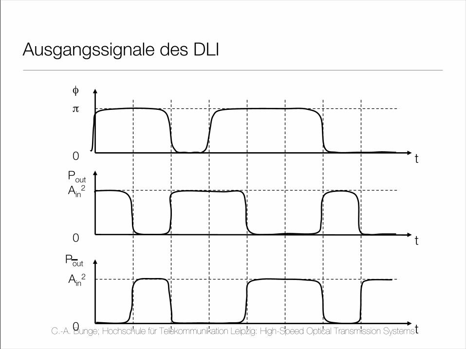
Ausgangssignale des DLI
t
φ
π
0
t
Pout
Ain2
0
t0
Pout
Ain2
C.-A. Bunge; Hochschule für Telekommunikation Leipzig: High-Speed Optical Transmission Systems
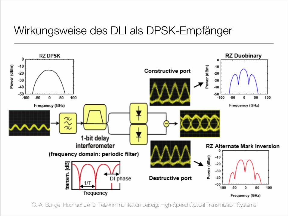
Wirkungsweise des DLI als DPSK-Empfänger
C.-A. Bunge; Hochschule für Telekommunikation Leipzig: High-Speed Optical Transmission Systems
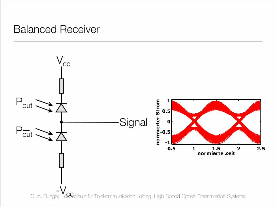
Balanced Receiver
Vcc
-Vcc
Signal
Pout
Pout
C.-A. Bunge; Hochschule für Telekommunikation Leipzig: High-Speed Optical Transmission Systems
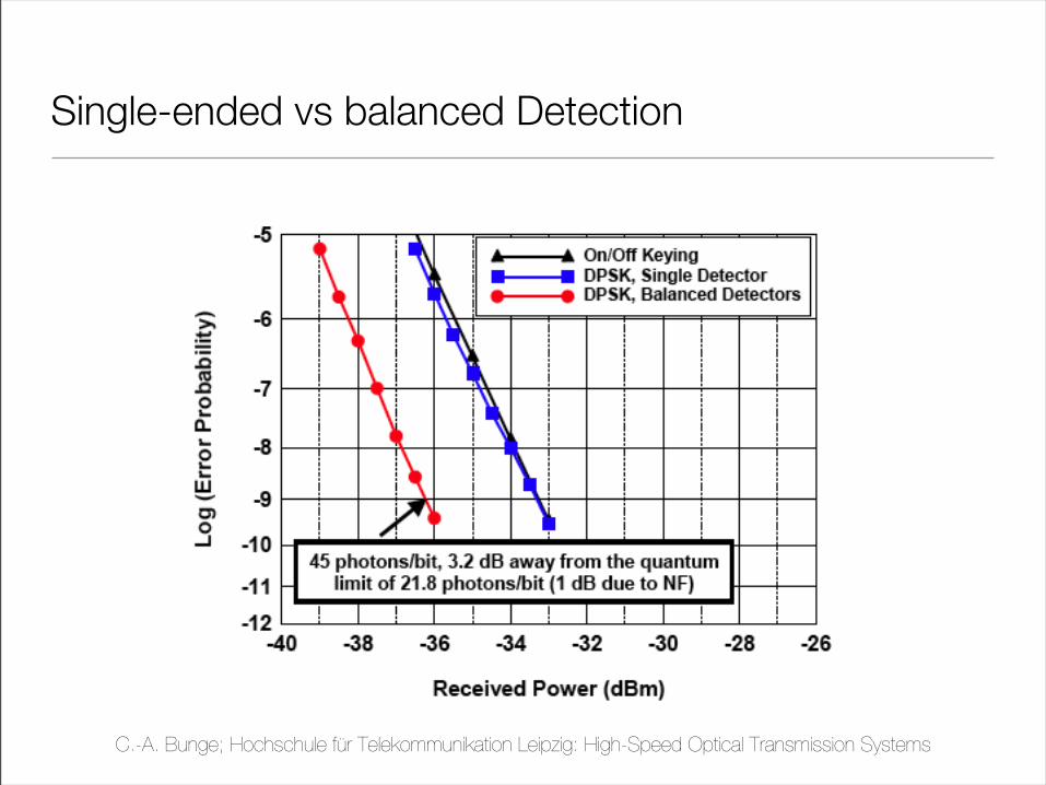
Single-ended vs balanced Detection
C.-A. Bunge; Hochschule für Telekommunikation Leipzig: High-Speed Optical Transmission Systems
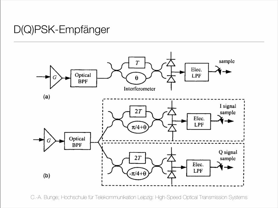
D(Q)PSK-Empfänger
C.-A. Bunge; Hochschule für Telekommunikation Leipzig: High-Speed Optical Transmission Systems
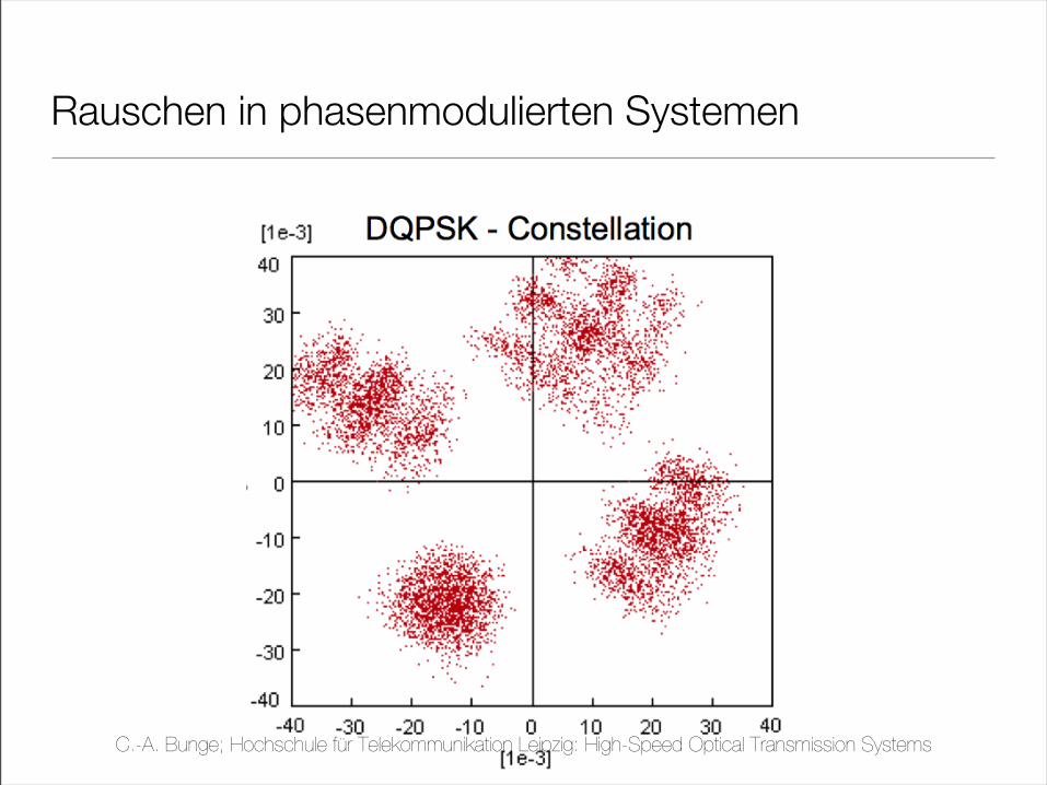
Rauschen in phasenmodulierten Systemen
C.-A. Bunge; Hochschule für Telekommunikation Leipzig: High-Speed Optical Transmission Systems
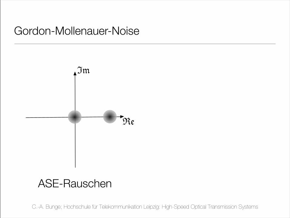
Gordon-Mollenauer-Noise
Im
Re
ASE-Rauschen
C.-A. Bunge; Hochschule für Telekommunikation Leipzig: High-Speed Optical Transmission Systems
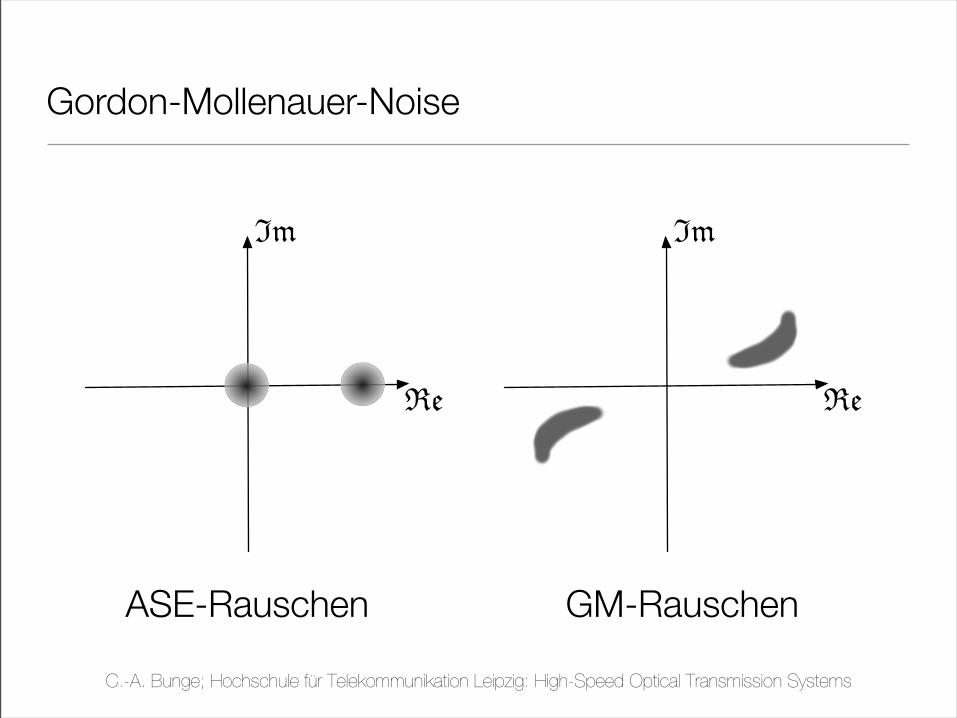
Gordon-Mollenauer-Noise
Im
Re
ASE-Rauschen
Im
Re
GM-Rauschen
C.-A. Bunge; Hochschule für Telekommunikation Leipzig: High-Speed Optical Transmission Systems
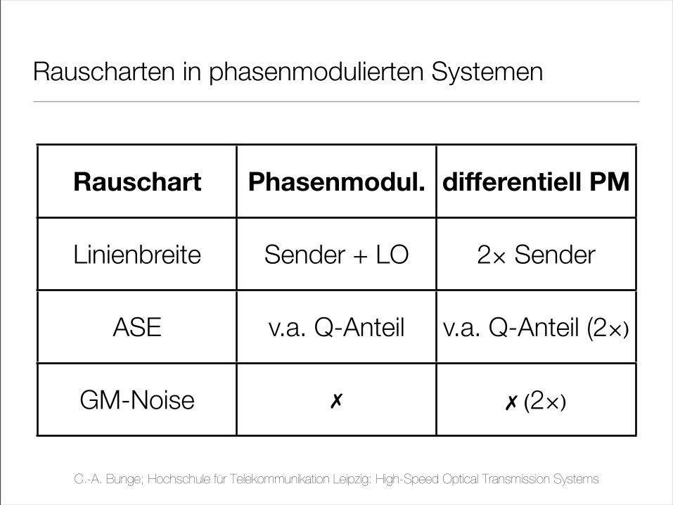
Rauscharten in phasenmodulierten Systemen
Rauschart Phasenmodul. differentiell PM
Linienbreite Sender + LO 2× Sender
ASE v.a. Q-Anteil v.a. Q-Anteil (2×)
GM-Noise ✗ ✗ (2×)
C.-A. Bunge; Hochschule für Telekommunikation Leipzig: High-Speed Optical Transmission Systems
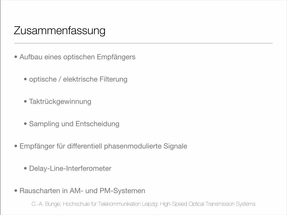
Zusammenfassung
• Aufbau eines optischen Empfängers
• optische / elektrische Filterung
• Taktrückgewinnung
• Sampling und Entscheidung
• Empfänger für differentiell phasenmodulierte Signale
• Delay-Line-Interferometer
• Rauscharten in AM- und PM-Systemen
C.-A. Bunge; Hochschule für Telekommunikation Leipzig: High-Speed Optical Transmission Systems