Embed Size (px)
Citation preview

11/12
DEEN
w w w . r i n g f e d e r . d e
Inspec t ion
Inde
x B,
11/
2012
· Id
. -
Nr.
149
9666
8
2 Inspection 01/2012
Inhalt | Content
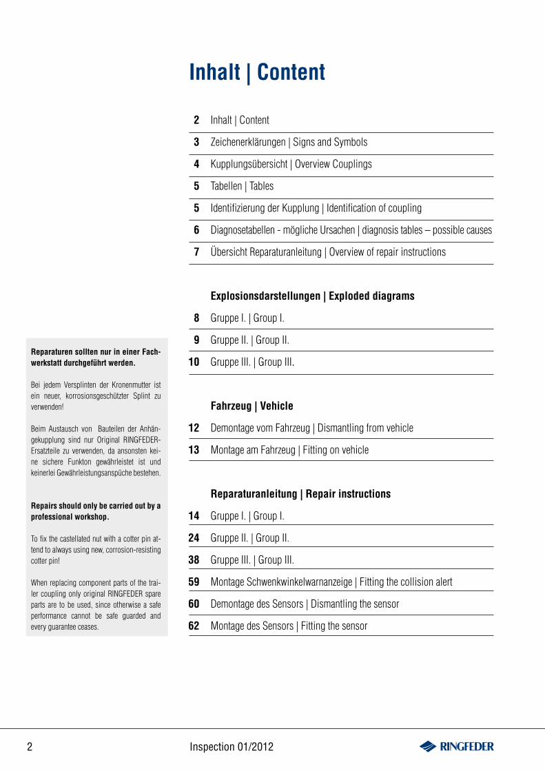
Inhalt | Content
Zeichenerklärungen | Signs and Symbols
Kupplungsübersicht | Overview Couplings
Tabellen | Tables
Identifizierung der Kupplung | Identification of coupling
Diagnosetabellen - mögliche Ursachen | diagnosis tables – possible causes
Übersicht Reparaturanleitung | Overview of repair instructions
Explosionsdarstellungen | Exploded diagrams
Gruppe I. | Group I.
Gruppe II. | Group II.
Gruppe III. | Group III.
Fahrzeug | Vehicle
Demontage vom Fahrzeug | Dismantling from vehicle
Montage am Fahrzeug | Fitting on vehicle
Reparaturanleitung | Repair instructions
Gruppe I. | Group I.
Gruppe II. | Group II.
Gruppe III. | Group III.
Montage Schwenkwinkelwarnanzeige | Fitting the collision alert
Demontage des Sensors | Dismantling the sensor
Montage des Sensors | Fitting the sensor
Reparaturen sollten nur in einer Fach-werkstatt durchgeführt werden.
Bei jedem Versplinten der Kronenmutter ist ein neuer, korrosionsgeschützter Splint zu verwenden!
Beim Austausch von Bauteilen der Anhän-gekupplung sind nur Original RINGFEDER- Ersatzteile zu verwenden, da ansonsten kei- ne sichere Funkton gewährleistet ist und keinerlei Gewährleistungsanspüche bestehen.
Repairs should only be carried out by a professional workshop.
To fix the castellated nut with a cotter pin at-tend to always using new, corrosion-resisting cotter pin!
When replacing component parts of the trai-ler coupling only original RINGFEDER spare parts are to be used, since otherwise a safe performance cannot be safe guarded and every guarantee ceases.
2
3
4
5
5
6
7
8
9
10
12
13
14
24
38
59
60
62
3www.ringfeder.de
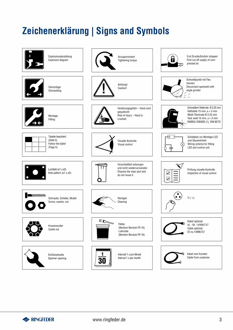
Zeichenerklärung | Signs and Symbols
Visuelle KontrolleVisual control
Verletzungsgefahr – Hand wird gequetschtRisk of injury – Hand is crushed
Tabelle beachten!(Seite 5)Follow the table!(Page 5)
Lochbild (e1 x e2) Hole pattern (e1 x e2)
Schraube, Scheibe, MutterScrew, washer, nut
KronenmutterCastle nut
SchlüsselweiteSpanner opening
ExplosionsdarstellungExplosion diagram
Schaltplan zur Montage LED und SteuereinheitWiring scheme for fitting LED and control unit
Prüfung visuelle KontrolleInspection of visual control
Erst Druckluftzufuhr stoppenFirst cut off supply of com-pressed air
Verschleißteil entsorgen und nicht wiederverwendenDispose the wear part and do not reuse it
ReinigenCleaning
Achtung!Caution!
Intervall 1 x pro MonatInterval 1 x per month
AnzugsmomentTightening torque
!DemontageDismantling
MontageFitting
Fetten(Bechem Berolub FR 16)Lubricate (Bechem Berulub FR 16)
Schweißpunkt mit Flex trennenDisconnect spotweld with angle grinder
Schweißen! Elektrode Ø 3,25 mm Heftstelle 15 mm, a = 3 mm Weld! Electrode Ø 3.25 mm Tack weld 15 mm, a = 3 mmENIBG3/ENIGB2 (1), DIN 8573!
+ -
Kabel optional Id. - Nr. 14996737Cable optionalID no.14996737
Kabel vom KundenCable from customer
V (- +)
4 Inspection 01/2012
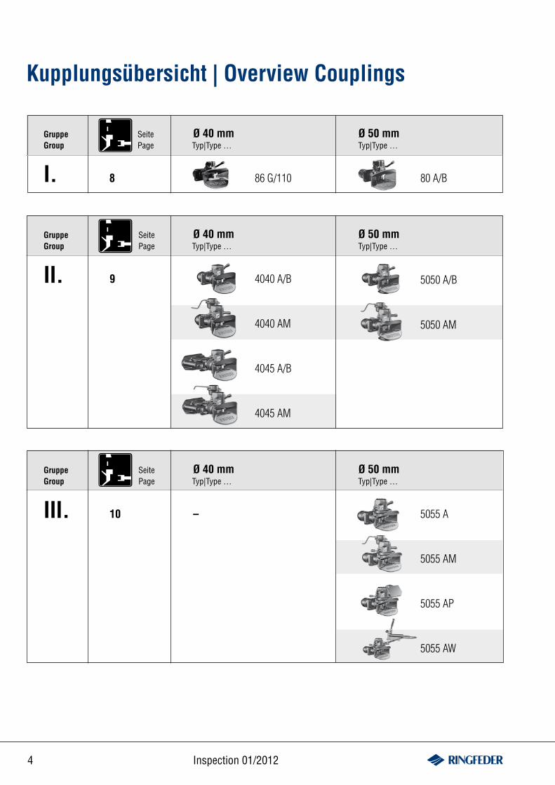
Kupplungsübersicht | Overview Couplings
I.
GruppeGroup
Ø 40 mm Ø 50 mmTyp|Type … Typ|Type …
80 A/B86 G/110
II.
GruppeGroup
Ø 40 mm Ø 50 mmTyp|Type … Typ|Type …
8
SeitePage
9
SeitePage
4040 A/B
4040 AM
4045 A/B
4045 AM
5050 A/B
5050 AM
III.
GruppeGroup
Ø 40 mm Ø 50 mmTyp|Type … Typ|Type …
10
SeitePage
– 5055 A
5055 AM
5055 AP
5055 AW
5www.ringfeder.de
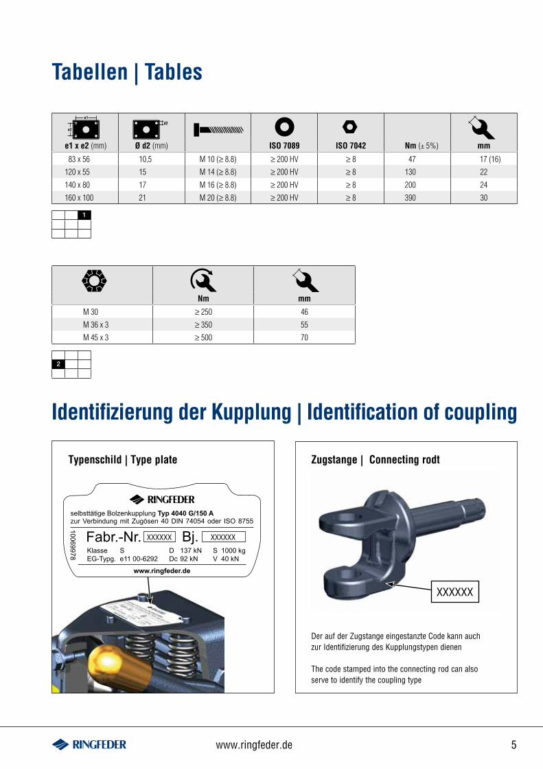
2
M 30 ≥ 250 46
M 36 x 3 ≥ 350 55
M 45 x 3 ≥ 500 70
Nm mm
1
83 x 56 10,5 M 10 (≥ 8.8) ≥ 200 HV ≥ 8 47 17 (16)
120 x 55 15 M 14 (≥ 8.8) ≥ 200 HV ≥ 8 130 22
140 x 80 17 M 16 (≥ 8.8) ≥ 200 HV ≥ 8 200 24
160 x 100 21 M 20 (≥ 8.8) ≥ 200 HV ≥ 8 390 30
e1 x e2 (mm) Ø d2 (mm) ISO 7089 ISO 7042 Nm (± 5%) mm
selbsttätige Bolzenkupplung Typ 4040 G/150 Azur Verbindung mit Zugösen 40 DIN 74054 oder ISO 8755
Fabr.-Nr. Bj.Klasse SEG-Typg. e11 00-6292
www.ringfeder.de
D 137 kNDc 92 kN
S 1000 kgV 40 kN
10069978Typenschild | Type plate
XXXXXX XXXXXX
Tabellen | Tables
Identifizierung der Kupplung | Identification of coupling
Zugstange | Connecting rodt
Der auf der Zugstange eingestanzte Code kann auch zur Identifizierung des Kupplungstypen dienen
The code stamped into the connecting rod can also serve to identify the coupling type
XXXXXX
6 Inspection 01/2012
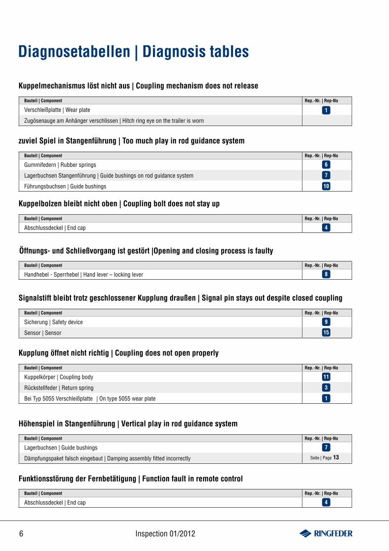
Diagnosetabellen | Diagnosis tables
Bauteil | Component Rep.-Nr. | Rep-No
Verschleißplatte | Wear plate
Zugösenauge am Anhänger verschlissen | Hitch ring eye on the trailer is worn
Kuppelmechanismus löst nicht aus | Coupling mechanism does not release
Bauteil | Component Rep.-Nr. | Rep-No
Gummifedern | Rubber springs
Lagerbuchsen Stangenführung | Guide bushings on rod guidance system
Führungsbuchsen | Guide bushings
zuviel Spiel in Stangenführung | Too much play in rod guidance system
Kuppelbolzen bleibt nicht oben | Coupling bolt does not stay up
Bauteil | Component Rep.-Nr. | Rep-No
Abschlussdeckel | End cap
Öffnungs- und Schließvorgang ist gestört |Opening and closing process is faulty
Bauteil | Component Rep.-Nr. | Rep-No
Handhebel - Sperrhebel | Hand lever – locking lever
Signalstift bleibt trotz geschlossener Kupplung draußen | Signal pin stays out despite closed coupling
Bauteil | Component Rep.-Nr. | Rep-No
Sicherung | Safety device
Sensor | Sensor
Bauteil | Component Rep.-Nr. | Rep-No
Kuppelkörper | Coupling body
Rückstellfeder | Return spring
Bei Typ 5055 Verschleißplatte | On type 5055 wear plate
Kupplung öffnet nicht richtig | Coupling does not open properly
Höhenspiel in Stangenführung | Vertical play in rod guidance system
Bauteil | Component Rep.-Nr. | Rep-No
Lagerbuchsen | Guide bushings
Dämpfungspaket falsch eingebaut | Damping assembly fitted incorrectly
6
7
10
4
8
9
15
11
3
1
Funktionsstörung der Fernbetätigung | Function fault in remote control
Bauteil | Component Rep.-Nr. | Rep-No
Abschlussdeckel | End cap
1
4
Seite | Page 13
7
7www.ringfeder.de
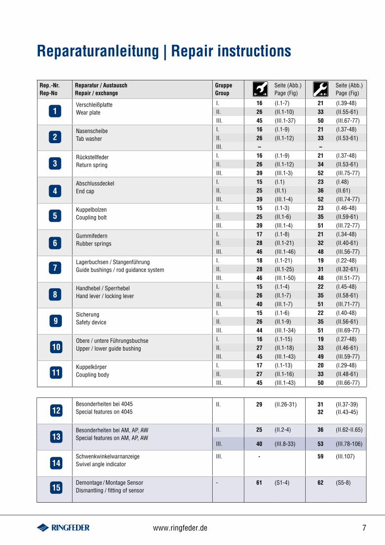
Rep.-Nr.Rep-No
Reparatur / AustauschRepair / exchange
GruppeGroup
Seite (Abb.)Page (Fig)
Seite (Abb.)Page (Fig)
Verschleißplatte Wear plate
I. 16 (I.1-7) 21 (I.39-48)II. 26 (II.1-10) 33 (II.55-61)III. 45 (III.1-37) 50 (III.67-77)
NasenscheibeTab washer
I. 16 (I.1-9) 21 (I.37-48)II. 26 (II.1-12) 33 (II.53-61)III. – –
RückstellfederReturn spring
I. 16 (I.1-9) 21 (I.37-48)II. 26 (II.1-12) 34 (II.53-61)III. 39 (III.1-3) 52 (III.75-77)
AbschlussdeckelEnd cap
I. 15 (I.1) 23 (I.48)II. 25 (II.1) 36 (II.61)III. 39 (III.1-4) 52 (III.74-77)
KuppelbolzenCoupling bolt
I. 15 (I.1-3) 23 (I.46-48)II. 25 (II.1-6) 35 (II.59-61)III. 39 (III.1-4) 51 (III.72-77)
GummifedernRubber springs
I. 17 (I.1-8) 21 (I.34-48)II. 28 (II.1-21) 32 (II.40-61)III. 46 (III.1-46) 48 (III.56-77)
Lagerbuchsen / StangenführungGuide bushings / rod guidance system
I. 18 (I.1-21) 19 (I.22-48)II. 28 (II.1-25) 31 (II.32-61)III. 46 (III.1-50) 48 (III.51-77)
Handhebel / SperrhebelHand lever / locking lever
I. 15 (I.1-4) 22 (I.45-48)II. 26 (II.1-7) 35 (II.58-61)III. 40 (III.1-7) 51 (III.71-77)
SicherungSafety device
I. 15 (I.1-6) 22 (I.40-48)II. 26 (II.1-9) 35 (II.56-61)III. 44 (III.1-34) 51 (III.69-77)
Obere / untere FührungsbuchseUpper / lower guide bushing
I. 16 (I.1-15) 19 (I.27-48)II. 27 (II.1-18) 33 (II.46-61)III. 45 (III.1-43) 49 (III.59-77)
KuppelkörperCoupling body
I. 17 (I.1-13) 20 (I.29-48)II. 27 (II.1-16) 33 (II.48-61)III. 45 (III.1-43) 50 (III.66-77)
Reparaturanleitung | Repair instructions
1
Besonderheiten bei 4045 Special features on 4045
II. 29 (II.26-31) 31 (II.37-39)32 (II.43-45)
Besonderheiten bei AM, AP, AWSpecial features on AM, AP, AW
II. 25 (II.2-4) 36 (II.62-II.65)
III. 40 (III.8-33) 53 (III.78-106)
SchwenkwinkelwarnanzeigeSwivel angle indicator
III. - 59 (III.107)
Demontage / Montage SensorDismantling / fitting of sensor
- 61 (S1-4) 62 (S5-8)
2
3
4
5
6
7
8
9
10
11
12
13
14
15
8 Inspection 01/2012
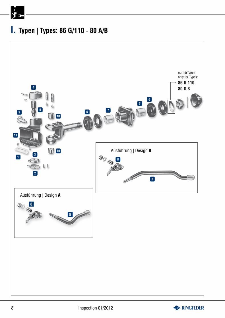
Ausführung | Design B
Ausführung | Design A
8
8
I. Typen | Types: 86 G/110 · 80 A/B
4
59
11
13
2
10
106 7
76
8
8
nur fürTypen only for Types:
86 G 11080 G 3
9www.ringfeder.de
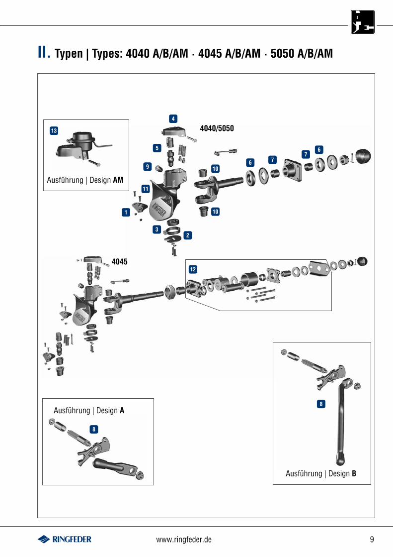
II. Typen | Types: 4040 A/B/AM · 4045 A/B/AM · 5050 A/B/AM
4040/5050
4045
Ausführung | Design AM
Ausführung | Design A
Ausführung | Design B
13
4
5
9
11
1
32
10
106
6
77
12
8
8
10 Inspection 01/2012
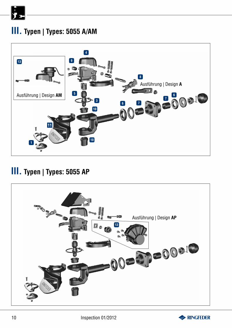
III. Typen | Types: 5055 A/AM
Ausführung | Design A
11
Ausführung | Design AM
13
4
9
5
3
10
10
6 77
6
8
1
III. Typen | Types: 5055 AP
13
Ausführung | Design AP
11www.ringfeder.de
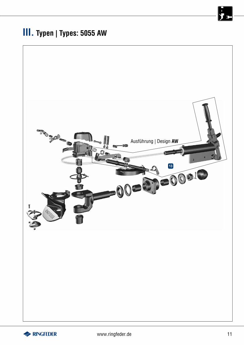
Ausführung | Design AW
13
III. Typen | Types: 5055 AW
12 Inspection 01/2012
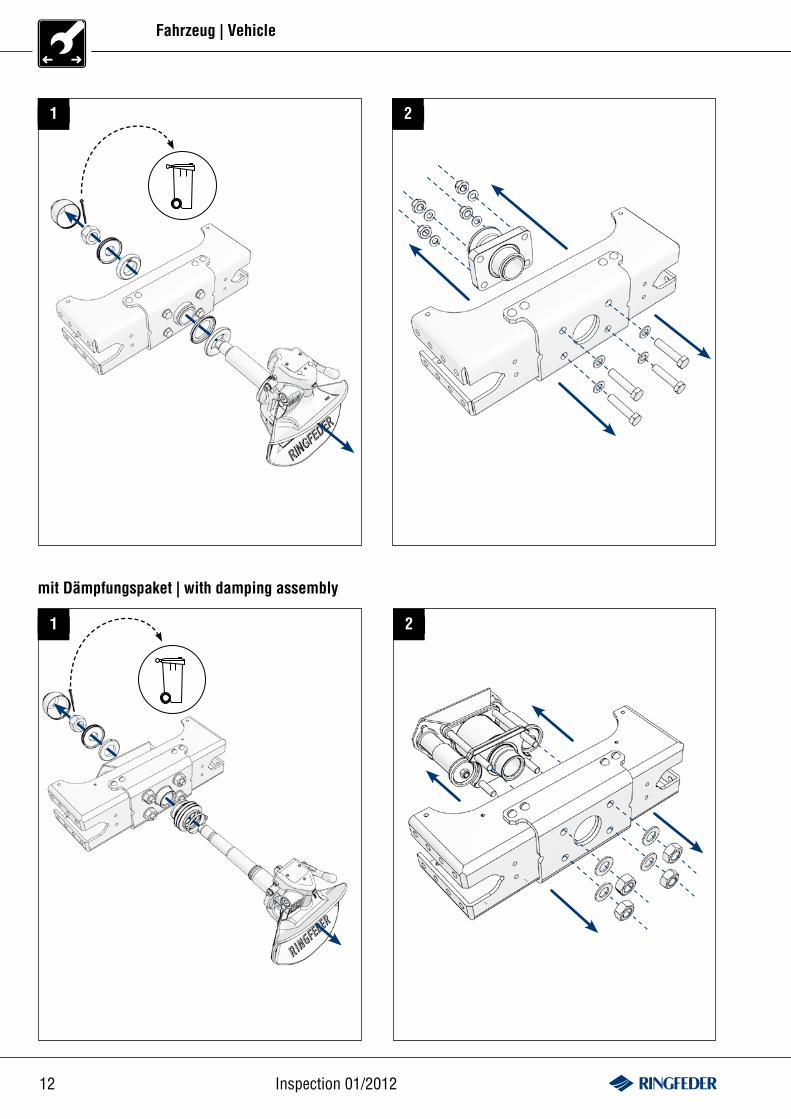
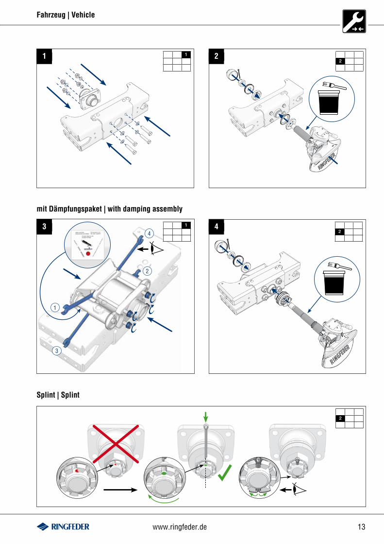
mit Dämpfungspaket | with damping assembly
1 2
1 2
Fahrzeug | Vehicle
13www.ringfeder.de
1
12
2
1 2
mit Dämpfungspaket | with damping assembly
3
Splint | Splint
Fahrzeug | Vehicle
42
1
2
3
4
14 Inspection 01/2012
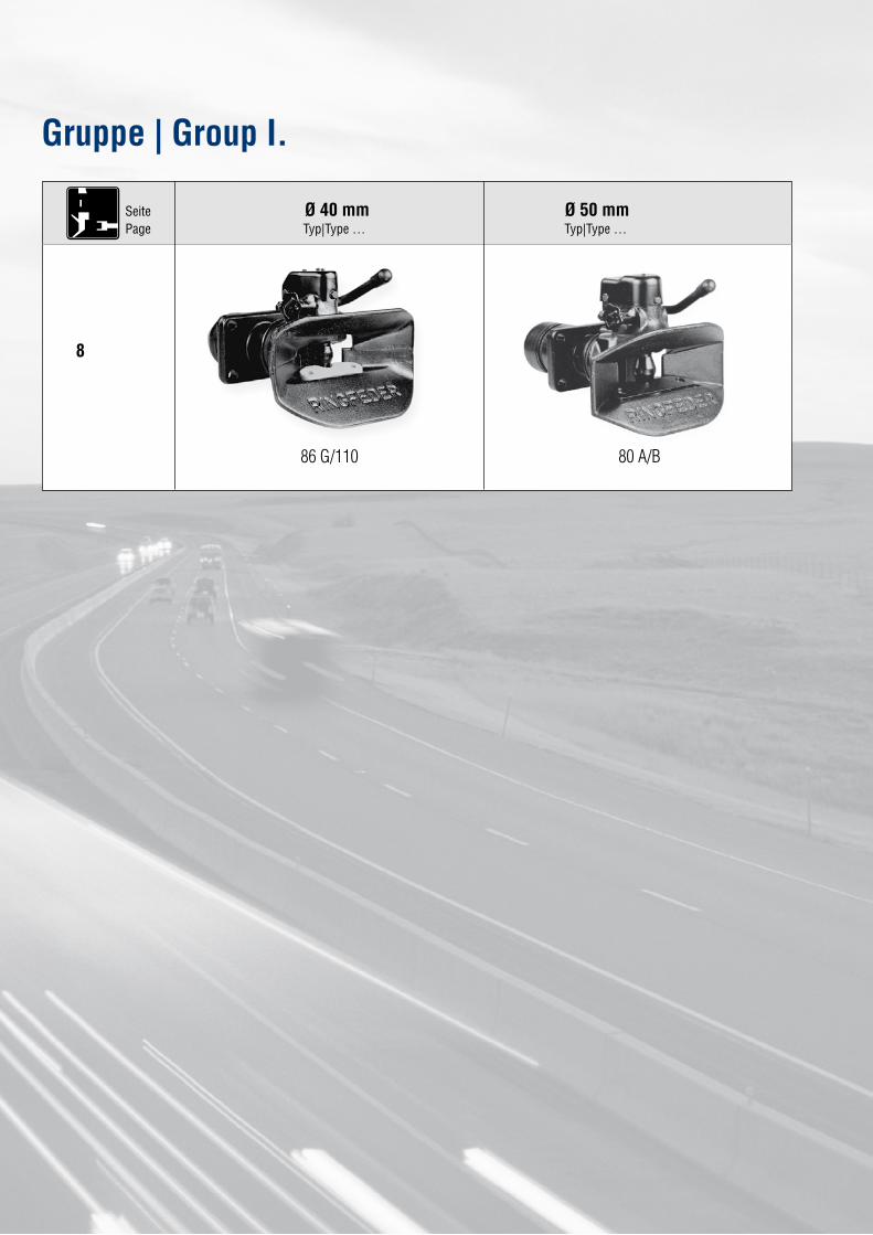
Ø 40 mm Ø 50 mmTyp|Type … Typ|Type …
86 G/110
8
SeitePage
80 A/B
Gruppe | Group I.
15www.ringfeder.de
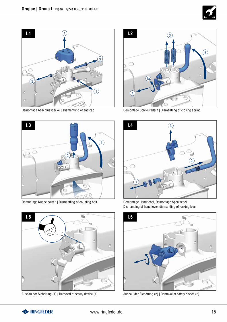
Gruppe | Group I. Typen | Types 86 G/110 · 80 A/B
Demontage Abschlussdeckel | Dismantling of end cap Demontage Schließfedern | Dismantling of closing spring
Demontage Kuppelbolzen | Dismantling of coupling bolt Demontage Handhebel, Demontage SperrhebelDismantling of hand lever, dismantling of locking lever
4
2
3
1
I.1 I.2
I.3 I.4
3
1
1a
2
1
2
3
2
1
Ausbau der Sicherung (1) | Removal of safety device (1) Ausbau der Sicherung (2) | Removal of safety device (2)
I.5 I.6

16 Inspection 01/2012
Gruppe | Group I. Typen | Types 86 G/110 · 80 A/B
Demontage Verschleißplatte | Dismantling of wear plate Drehung der Kupplung | Rotation of coupling
180°I.7 I.8
Demontage der Nasenscheibe, Demontage der RückstellfederDismantling of the tab washer, dismantling of the return springs
Demontage der unteren Führungsbuchse und des Kuppelkörpers (1)Dismantling of the lower guide bushing and the coupling assembly (1)
I.9 I.10
I.11 I.12
Demontage der unteren Führungsbuchse und des Kuppelkörpers (2)Dismantling of the lower guide bushing and the coupling assembly (2)
Demontage der unteren Führungsbuchse und des Kuppelkörpers (3)Dismantling of the lower guide bushing and the coupling assembly (3)
2
1
17www.ringfeder.de
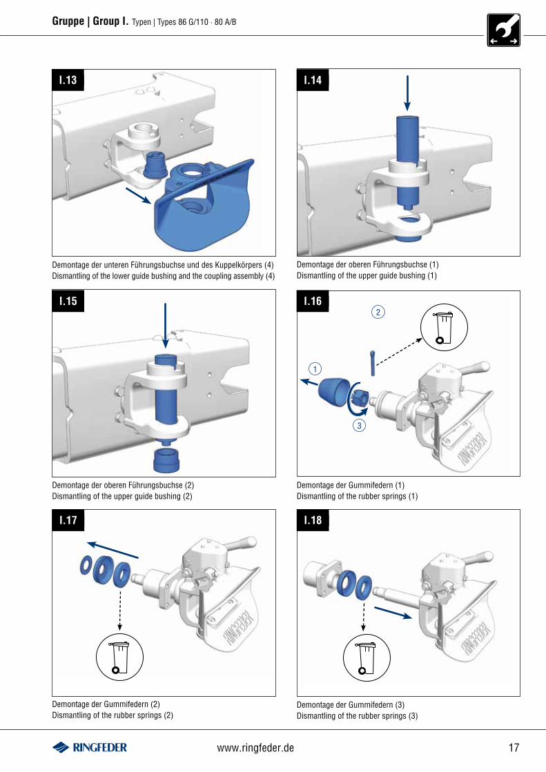
Gruppe | Group I. Typen | Types 86 G/110 · 80 A/B
Demontage der unteren Führungsbuchse und des Kuppelkörpers (4)Dismantling of the lower guide bushing and the coupling assembly (4)
Demontage der oberen Führungsbuchse (1)Dismantling of the upper guide bushing (1)
I.13 I.14
Demontage der oberen Führungsbuchse (2)Dismantling of the upper guide bushing (2)
Demontage der Gummifedern (1)Dismantling of the rubber springs (1)
I.15 I.16
1
2
3
Demontage der Gummifedern (2)Dismantling of the rubber springs (2)
Demontage der Gummifedern (3)Dismantling of the rubber springs (3)
I.17 I.18
18 Inspection 01/2012
Gruppe | Group I. Typen | Types 86 G/110 · 80 A/B
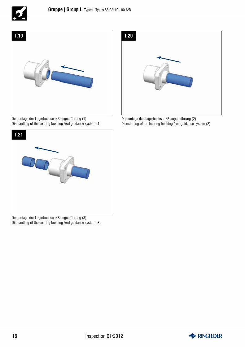
I.19 I.20
Demontage der Lagerbuchsen / Stangenführung (1)Dismantling of the bearing bushing /rod guidance system (1)
Demontage der Lagerbuchsen / Stangenführung (2)Dismantling of the bearing bushing /rod guidance system (2)
I.21
Demontage der Lagerbuchsen / Stangenführung (3)Dismantling of the bearing bushing /rod guidance system (3)
19www.ringfeder.de
Gruppe | Group I. Typen | Types 86 G/110 · 80 A/B
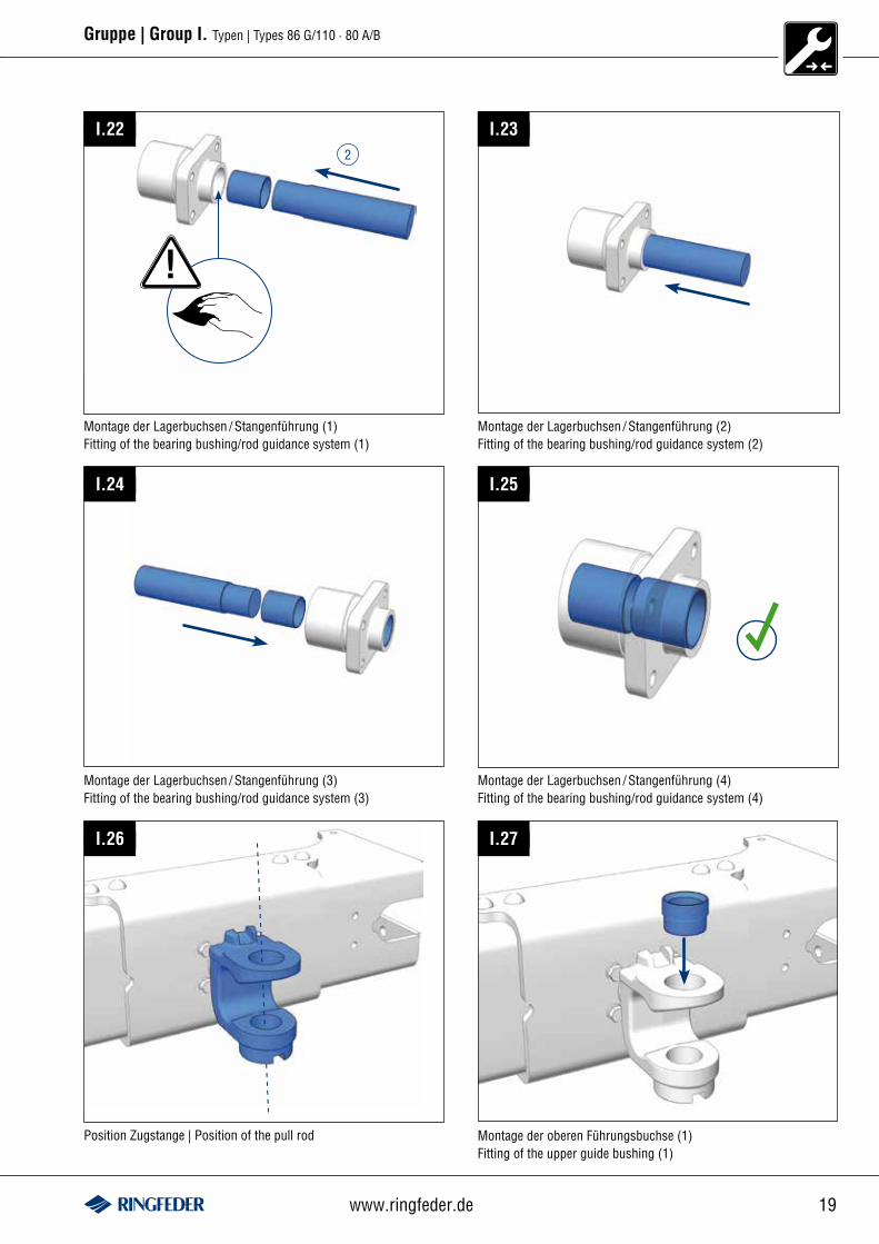
I.22
Montage der Lagerbuchsen / Stangenführung (1)Fitting of the bearing bushing/rod guidance system (1)
2
!
I.23
Montage der Lagerbuchsen / Stangenführung (2)Fitting of the bearing bushing/rod guidance system (2)
I.24 I.25
Montage der Lagerbuchsen / Stangenführung (3)Fitting of the bearing bushing/rod guidance system (3)
Montage der Lagerbuchsen / Stangenführung (4)Fitting of the bearing bushing/rod guidance system (4)
Position Zugstange | Position of the pull rod
I.26 I.27
Montage der oberen Führungsbuchse (1)Fitting of the upper guide bushing (1)
20 Inspection 01/2012
Gruppe | Group I. Typen | Types 86 G/110 · 80 A/B
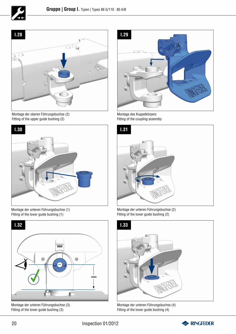
I.28
Montage der oberen Führungsbuchse (2)Fitting of the upper guide bushing (2)
I.29
Montage des Kuppelkörpers Fitting of the coupling assembly
I.30
Montage der unteren Führungsbuchse (1)Fitting of the lower guide bushing (1)
I.31
Montage der unteren Führungsbuchse (2)Fitting of the lower guide bushing (2)
I.32
Montage der unteren Führungsbuchse (3)Fitting of the lower guide bushing (3)
Montage der unteren Führungsbuchse (4)Fitting of the lower guide bushing (4)
I.33
21www.ringfeder.de
Gruppe | Group I. Typen | Types 86 G/110 · 80 A/B
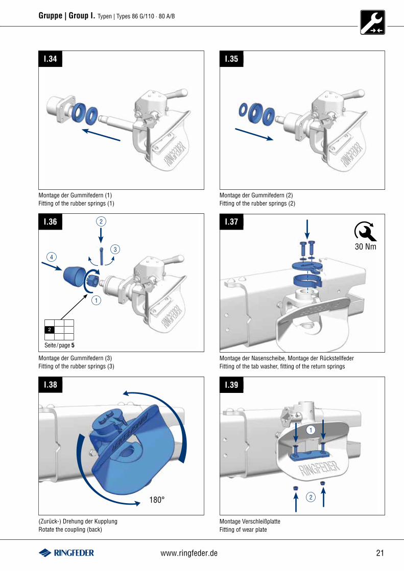
I.34
Montage der Gummifedern (1)Fitting of the rubber springs (1)
I.35
Montage der Gummifedern (2)Fitting of the rubber springs (2)
I.36 2
4
1
Seite /page 5
2
I.37
Montage der Gummifedern (3)Fitting of the rubber springs (3)
30 Nm
I.38
180°
I.39
2
1
Montage der Nasenscheibe, Montage der RückstellfederFitting of the tab washer, fitting of the return springs
(Zurück-) Drehung der KupplungRotate the coupling (back)
Montage VerschleißplatteFitting of wear plate
3
22 Inspection 01/2012
Gruppe | Group I. Typen | Types 86 G/110 · 80 A/B
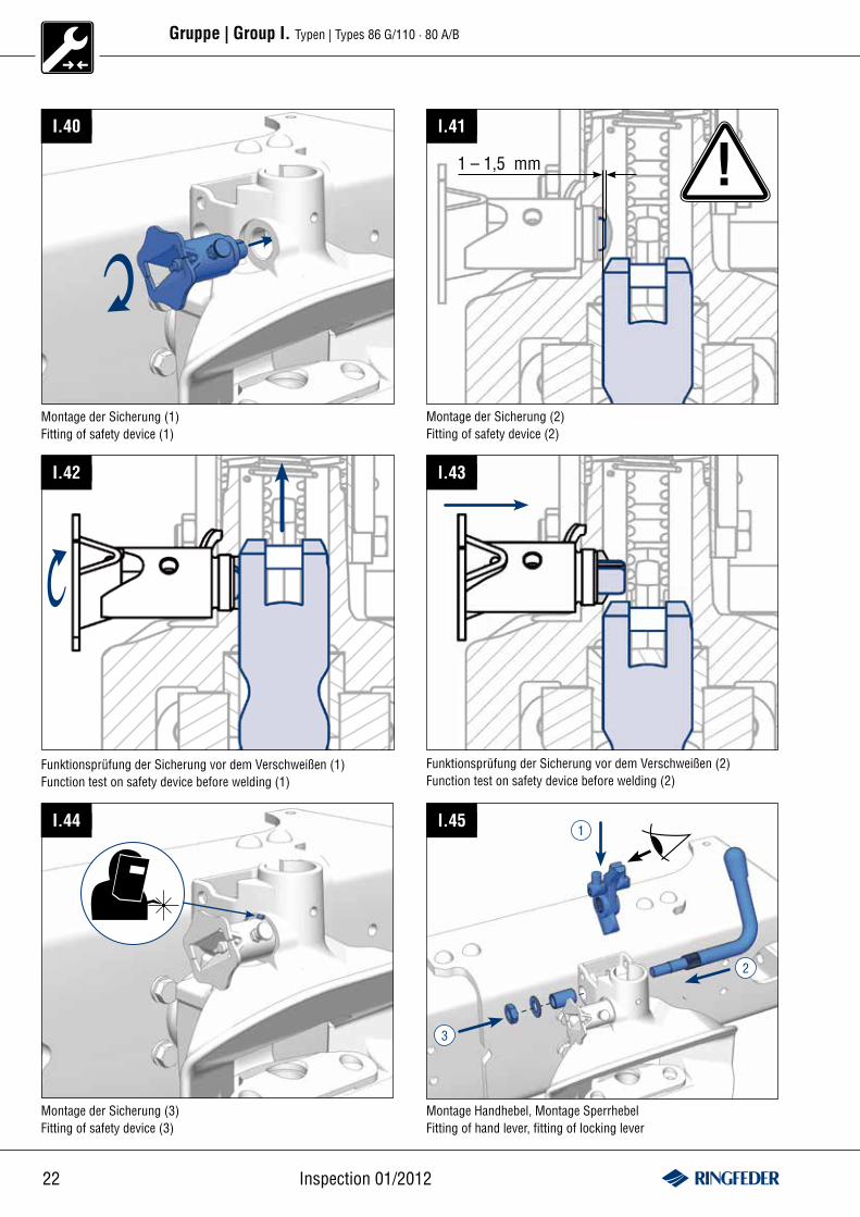
I.40
Montage der Sicherung (1)Fitting of safety device (1)
!1 – 1,5 mm
I.41
Montage der Sicherung (2)Fitting of safety device (2)
I.42 I.43
Funktionsprüfung der Sicherung vor dem Verschweißen (1)Function test on safety device before welding (1)
Funktionsprüfung der Sicherung vor dem Verschweißen (2)Function test on safety device before welding (2)
I.44 I.45
Montage der Sicherung (3)Fitting of safety device (3)
Montage Handhebel, Montage SperrhebelFitting of hand lever, fitting of locking lever
2
1
3
23www.ringfeder.de
Gruppe | Group I. Typen | Types 86 G/110 · 80 A/B
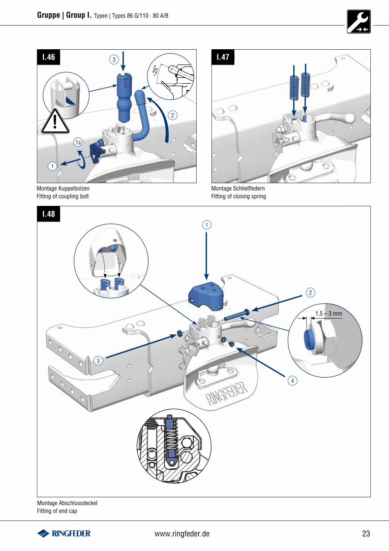
I.46
1
1a
3
~25°
2
Montage KuppelbolzenFitting of coupling bolt
I.47
Montage SchließfedernFitting of closing spring
I.481
3
2
4
Montage AbschlussdeckelFitting of end cap
!
1,5 – 3 mm
24 Inspection 01/2012
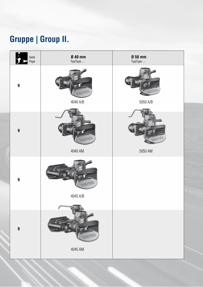
Ø 40 mm Ø 50 mmTyp|Type … Typ|Type …
4040 A/B
9
5050 A/B
4040 AM
4045 A/B
5050 AM
SeitePage
4045 AM
Gruppe | Group II.
9
9
9
25www.ringfeder.de
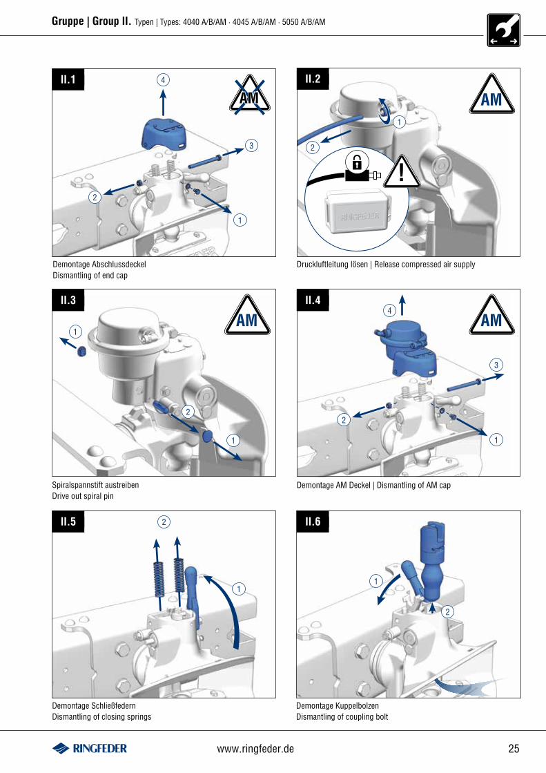
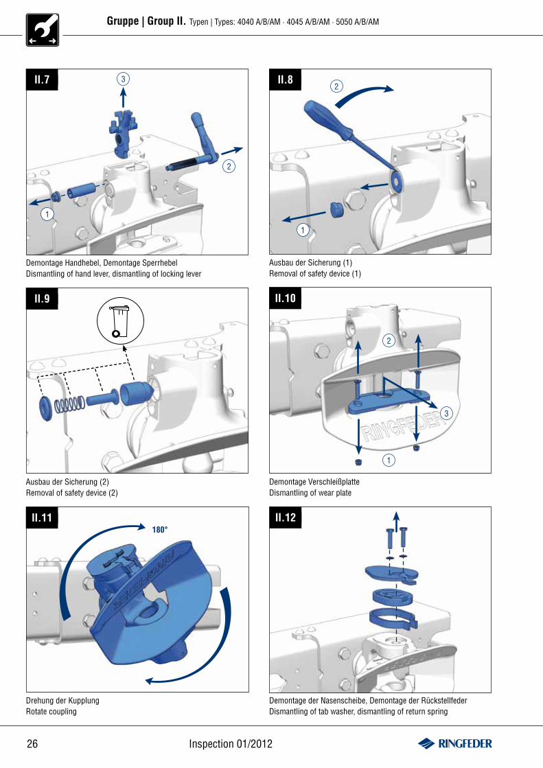
Gruppe | Group II. Typen | Types: 4040 A/B/AM · 4045 A/B/AM · 5050 A/B/AM
II.1
Demontage AbschlussdeckelDismantling of end cap
AM4
2
3
1
AMII.2
!2
1
Druckluftleitung lösen | Release compressed air supply
II.3
1
2
1
AM
Spiralspannstift austreibenDrive out spiral pin
AM4
2
3
1
Demontage AM Deckel | Dismantling of AM cap
II.4
II.5
1
2
Demontage SchließfedernDismantling of closing springs
1
II.6
2
Demontage KuppelbolzenDismantling of coupling bolt
26 Inspection 01/2012
Gruppe | Group II. Typen | Types: 4040 A/B/AM · 4045 A/B/AM · 5050 A/B/AM
II.7 3
1
2
Demontage Handhebel, Demontage SperrhebelDismantling of hand lever, dismantling of locking lever
1
2II.8
Ausbau der Sicherung (1)Removal of safety device (1)
II.9
Ausbau der Sicherung (2)Removal of safety device (2)
II.10
Demontage VerschleißplatteDismantling of wear plate
1
2
II.11180°
Drehung der KupplungRotate coupling
II.12
Demontage der Nasenscheibe, Demontage der RückstellfederDismantling of tab washer, dismantling of return spring
3
27www.ringfeder.de
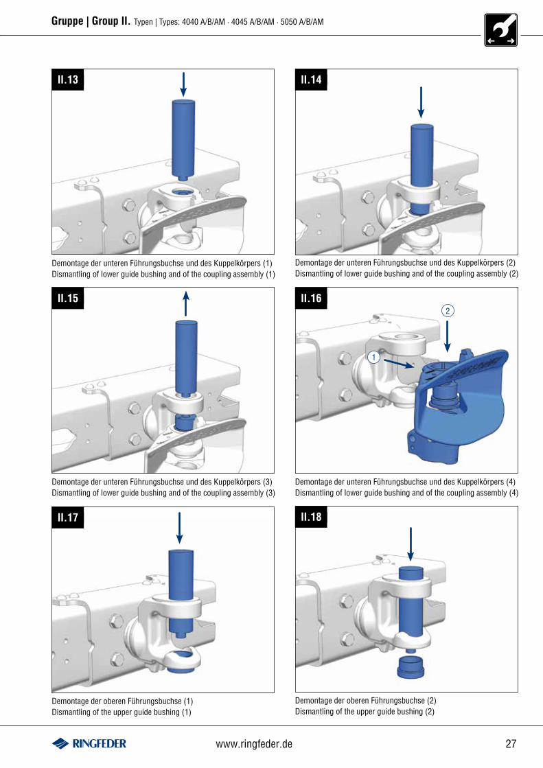
Gruppe | Group II. Typen | Types: 4040 A/B/AM · 4045 A/B/AM · 5050 A/B/AM
II.13
Demontage der unteren Führungsbuchse und des Kuppelkörpers (1)Dismantling of lower guide bushing and of the coupling assembly (1)
II.14
Demontage der unteren Führungsbuchse und des Kuppelkörpers (2)Dismantling of lower guide bushing and of the coupling assembly (2)
II.15
Demontage der unteren Führungsbuchse und des Kuppelkörpers (3)Dismantling of lower guide bushing and of the coupling assembly (3)
II.16
Demontage der unteren Führungsbuchse und des Kuppelkörpers (4)Dismantling of lower guide bushing and of the coupling assembly (4)
1
2
II.17 II.18
Demontage der oberen Führungsbuchse (1)Dismantling of the upper guide bushing (1)
Demontage der oberen Führungsbuchse (2)Dismantling of the upper guide bushing (2)
28 Inspection 01/2012
Gruppe | Group II. Typen | Types: 4040 A/B/AM · 4045 A/B/AM · 5050 A/B/AM
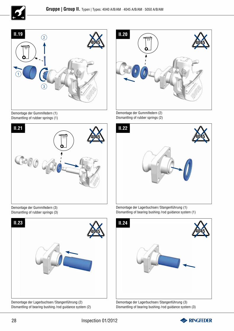
II.19
4045
3
1
2II.20
4045
Demontage der Gummifedern (1)Dismantling of rubber springs (1)
Demontage der Gummifedern (2)Dismantling of rubber springs (2)
II.21
Demontage der Gummifedern (3)Dismantling of rubber springs (3)
4045
II.22
Demontage der Lagerbuchsen / Stangenführung (1)Dismantling of bearing bushing /rod guidance system (1)
4045
II.23
Demontage der Lagerbuchsen / Stangenführung (2)Dismantling of bearing bushing /rod guidance system (2)
II.24
Demontage der Lagerbuchsen / Stangenführung (3)Dismantling of bearing bushing /rod guidance system (3)
4045 4045
29www.ringfeder.de
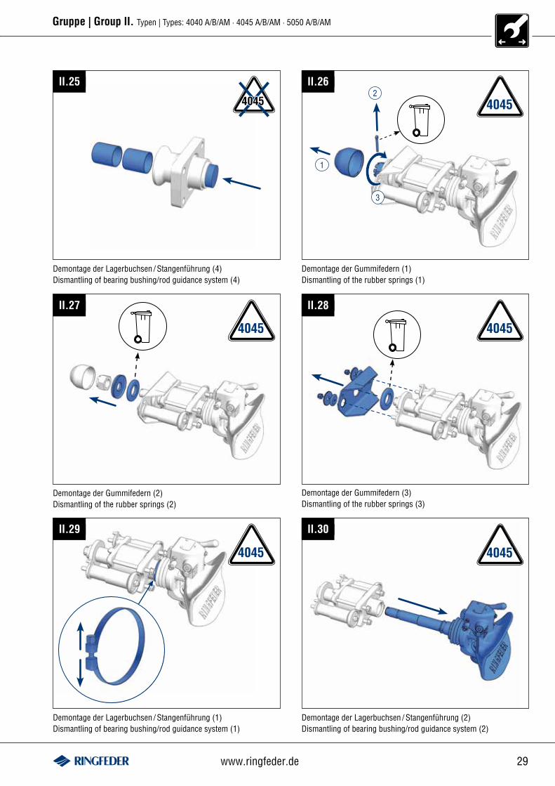
Gruppe | Group II. Typen | Types: 4040 A/B/AM · 4045 A/B/AM · 5050 A/B/AM
II.25
Demontage der Lagerbuchsen / Stangenführung (4)Dismantling of bearing bushing/rod guidance system (4)
4045
II.26
4045
3
1
2
Demontage der Gummifedern (1)Dismantling of the rubber springs (1)
II.27
Demontage der Gummifedern (2)Dismantling of the rubber springs (2)
Demontage der Gummifedern (3)Dismantling of the rubber springs (3)
II.28
II.29
4045 4045
Demontage der Lagerbuchsen / Stangenführung (1)Dismantling of bearing bushing/rod guidance system (1)
4045 4045
Demontage der Lagerbuchsen / Stangenführung (2)Dismantling of bearing bushing/rod guidance system (2)
II.30
30 Inspection 01/2012
Gruppe | Group II. Typen | Types: 4040 A/B/AM · 4045 A/B/AM · 5050 A/B/AM
4045
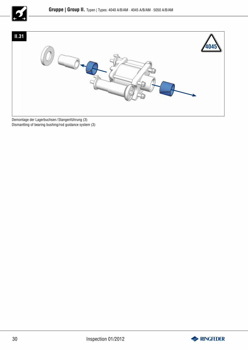
II.31
Demontage der Lagerbuchsen / Stangenführung (3)Dismantling of bearing bushing/rod guidance system (3)
31www.ringfeder.de
Gruppe | Group II. Typen | Types: 4040 A/B/AM · 4045 A/B/AM · 5050 A/B/AM
4045
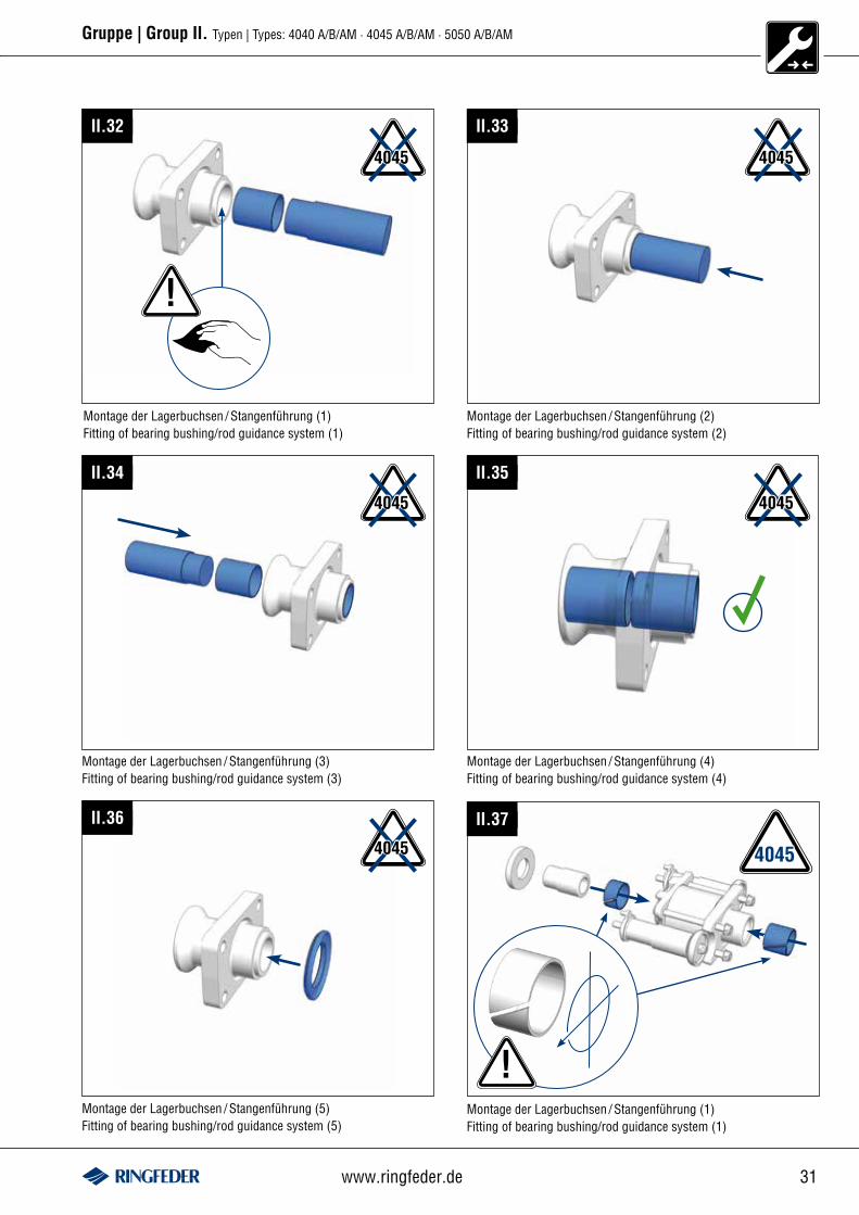
II.32
!
Montage der Lagerbuchsen / Stangenführung (1)Fitting of bearing bushing/rod guidance system (1)
II.33
Montage der Lagerbuchsen / Stangenführung (2)Fitting of bearing bushing/rod guidance system (2)
4045
4045
Montage der Lagerbuchsen / Stangenführung (3)Fitting of bearing bushing/rod guidance system (3)
II.34
Montage der Lagerbuchsen / Stangenführung (4)Fitting of bearing bushing/rod guidance system (4)
II.35
4045
II.36
4045
Montage der Lagerbuchsen / Stangenführung (5)Fitting of bearing bushing/rod guidance system (5)
4045
II.37
!Montage der Lagerbuchsen / Stangenführung (1)Fitting of bearing bushing/rod guidance system (1)
32 Inspection 01/2012
Gruppe | Group II. Typen | Types: 4040 A/B/AM · 4045 A/B/AM · 5050 A/B/AM
4045
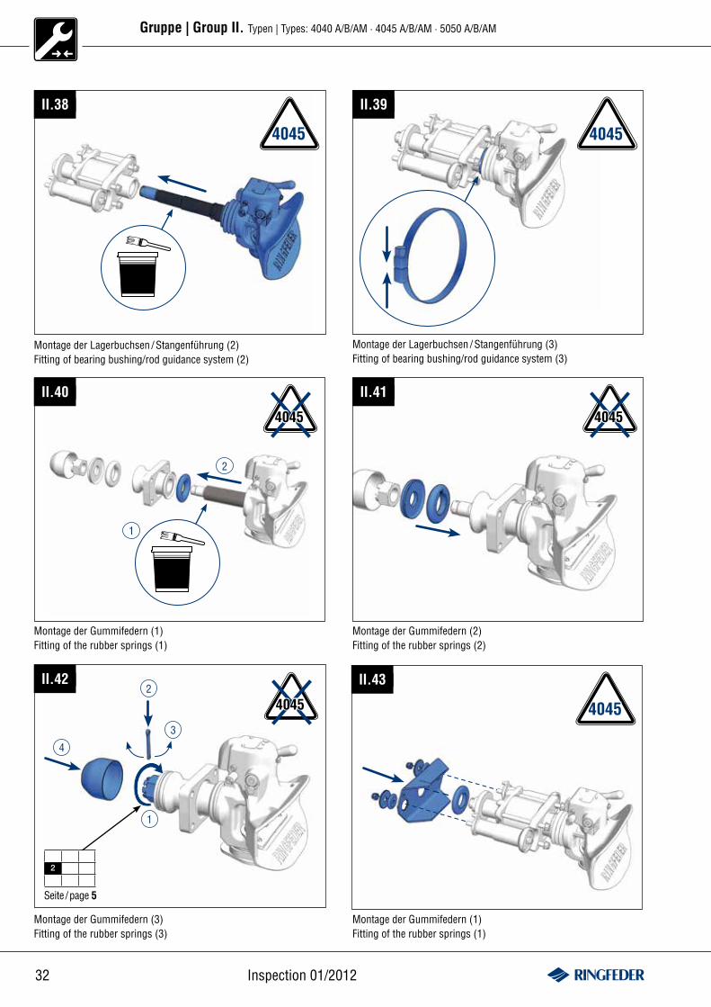
II.38
Montage der Lagerbuchsen / Stangenführung (2)Fitting of bearing bushing/rod guidance system (2)
II.39
Montage der Lagerbuchsen / Stangenführung (3)Fitting of bearing bushing/rod guidance system (3)
4045
II.40
4045
Montage der Gummifedern (1)Fitting of the rubber springs (1)
1
2
II.41
4045
Montage der Gummifedern (2)Fitting of the rubber springs (2)
II.422
4
1
Seite /page 5
2
3
4045
Montage der Gummifedern (3)Fitting of the rubber springs (3)
II.43
4045
Montage der Gummifedern (1)Fitting of the rubber springs (1)
33www.ringfeder.de
Gruppe | Group II. Typen | Types: 4040 A/B/AM · 4045 A/B/AM · 5050 A/B/AM
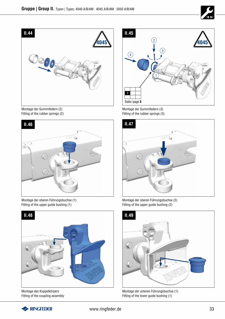
II.44
4045
Montage der Gummifedern (2)Fitting of the rubber springs (2)
40452
4
1
Seite /page 5
2
3
Montage der Gummifedern (3)Fitting of the rubber springs (3)
II.45
II.46
Montage der oberen Führungsbuchse (1)Fitting of the upper guide bushing (1)
II.47
Montage der oberen Führungsbuchse (2)Fitting of the upper guide bushing (2)
II.48
Montage des KuppelkörpersFitting of the coupling assembly
II.49
Montage der unteren Führungsbuchse (1)Fitting of the lower guide bushing (1)
34 Inspection 01/2012
Gruppe | Group II. Typen | Types: 4040 A/B/AM · 4045 A/B/AM · 5050 A/B/AM
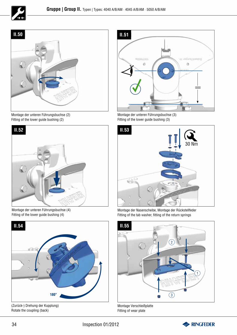
II.50
Montage der unteren Führungsbuchse (2)Fitting of the lower guide bushing (2)
II.51
Montage der unteren Führungsbuchse (3)Fitting of the lower guide bushing (3)
II.52
Montage der unteren Führungsbuchse (4)Fitting of the lower guide bushing (4)
II.53
30 Nm
Montage der Nasenscheibe, Montage der RückstellfederFitting of the tab washer, fitting of the return springs
II.54
180°
(Zurück-) Drehung der Kupplung)Rotate the coupling (back)
II.55
3
2
Montage VerschleißplatteFitting of wear plate
1
35www.ringfeder.de
Gruppe | Group II. Typen | Types: 4040 A/B/AM · 4045 A/B/AM · 5050 A/B/AM
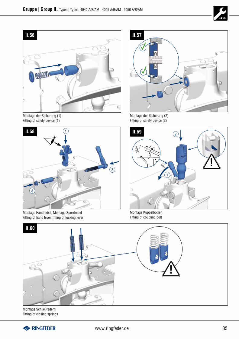
II.56
Montage der Sicherung (1)Fitting of safety device (1)
II.57
II.58 1
3
2
II.59
!
~25°
1
2
Montage Handhebel, Montage SperrhebelFitting of hand lever, fitting of locking lever
Montage KuppelbolzenFitting of coupling bolt
II.60
!
Montage SchließfedernFitting of closing springs
Montage der Sicherung (2)Fitting of safety device (2)
36 Inspection 01/2012
Gruppe | Group II. Typen | Types: 4040 A/B/AM · 4045 A/B/AM · 5050 A/B/AM
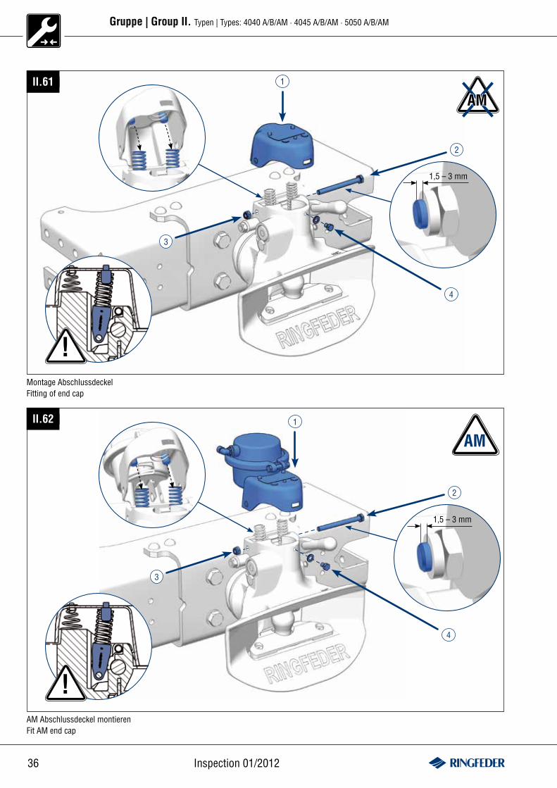
II.61
AM1
2
3
4
Montage AbschlussdeckelFitting of end cap
1,5 – 3 mm
!
II.62 1
2
3
4
AM Abschlussdeckel montierenFit AM end cap
1,5 – 3 mm
!
AM
37www.ringfeder.de
Gruppe | Group II. Typen | Types: 4040 A/B/AM · 4045 A/B/AM · 5050 A/B/AM
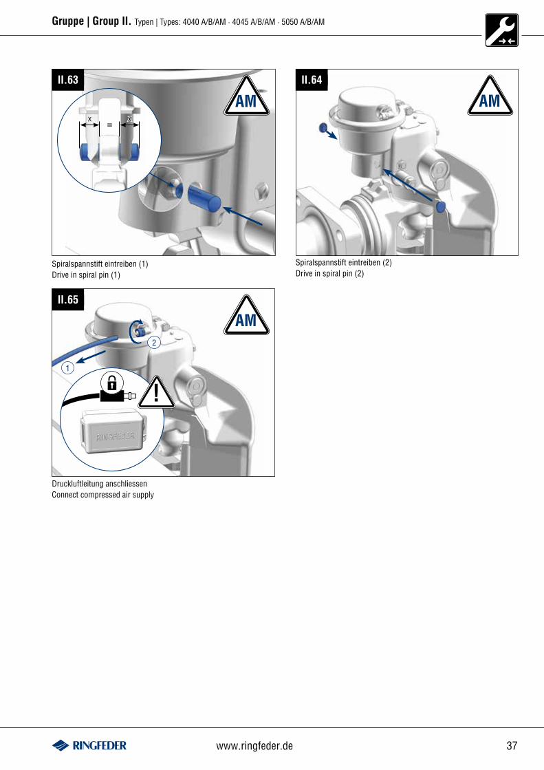
II.63
AM
Spiralspannstift eintreiben (1)Drive in spiral pin (1)
AM
Spiralspannstift eintreiben (2)Drive in spiral pin (2)
II.64
AMII.65
!1
2
Druckluftleitung anschliessenConnect compressed air supply
x x=
38 Inspection 01/2012
Ø 40 mm Ø 50 mmTyp|Type … Typ|Type …
–10
–
–
SeitePage
–
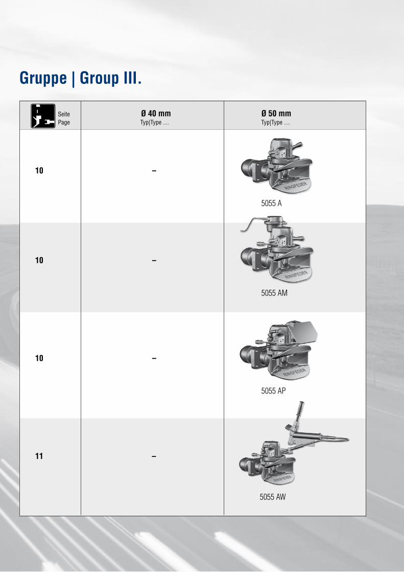
Gruppe | Group III.
10
10
11
5055 A
5055 AM
5055 AP
5055 AW
39www.ringfeder.de
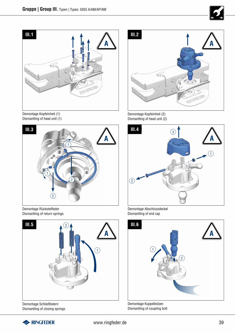
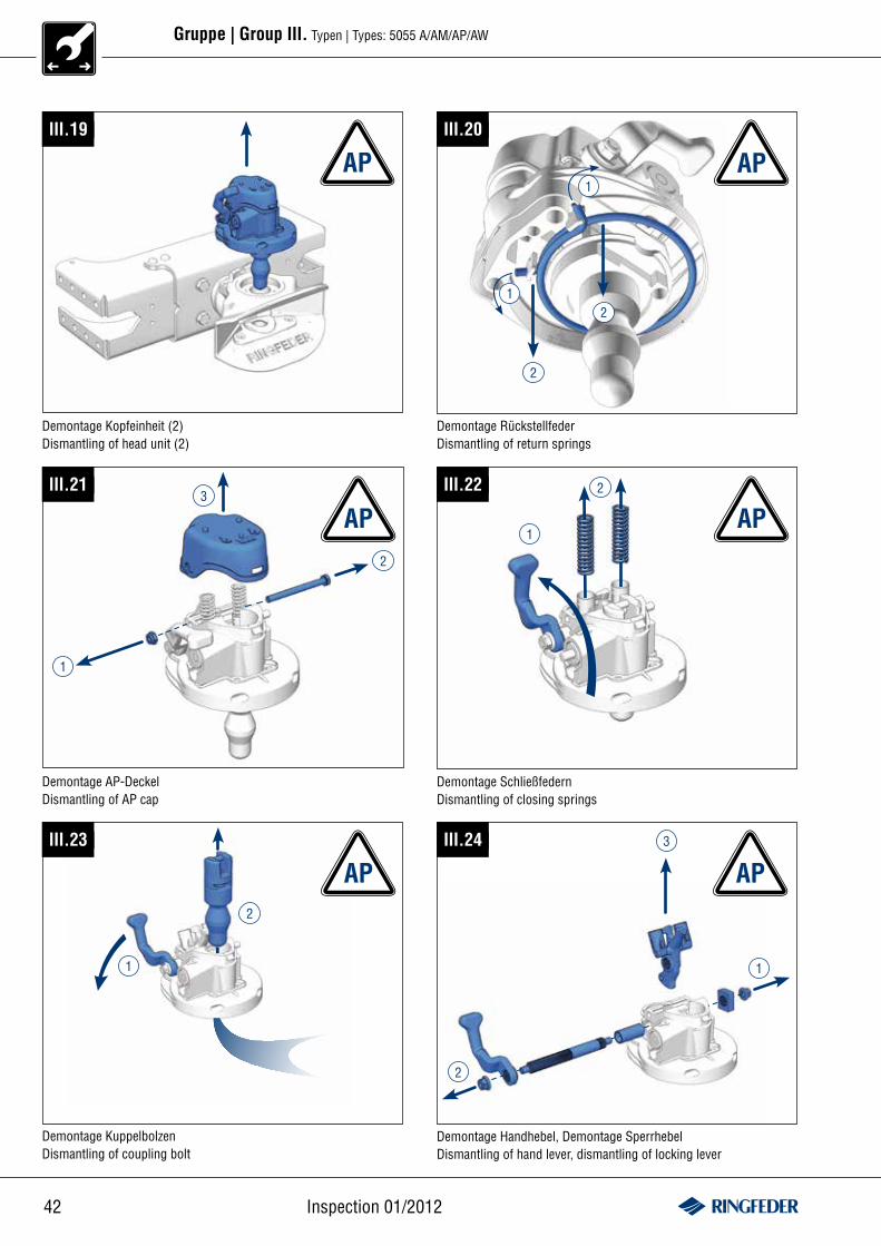
Gruppe | Group III. Typen | Types: 5055 A/AM/AP/AW
Demontage Kopfeinheit (1)Dismantling of head unit (1)
III.1
A
Demontage Kopfeinheit (2)Dismantling of head unit (2)
III.2
A
III.3
A1
1
2
2
Demontage RückstellfederDismantling of return springs
III.4
A
Demontage AbschlussdeckelDismantling of end cap
1
2
3
Demontage SchließfedernDismantling of closing springs
III.5
1
2
A A
1
III.6
2
Demontage KuppelbolzenDismantling of coupling bolt
40 Inspection 01/2012
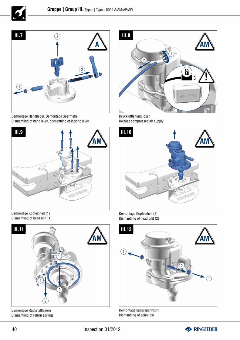
Gruppe | Group III. Typen | Types: 5055 A/AM/AP/AW
III.7
Demontage Handhebel, Demontage SperrhebelDismantling of hand lever, dismantling of locking lever
1
2
3 III.8
AMA
!
1
2
Druckluftleitung lösenRelease compressed air supply
III.9
Demontage Kopfeinheit (1)Dismantling of head unit (1)
III.10
AM AM
Demontage Kopfeinheit (2)Dismantling of head unit (2)
III.11
1
1
2
2
Demontage RückstellfedernDismantling of return springs
AMIII.12
AM
1
1
2
Demontage SpiralspannstiftDismantling of spiral pin
41www.ringfeder.de
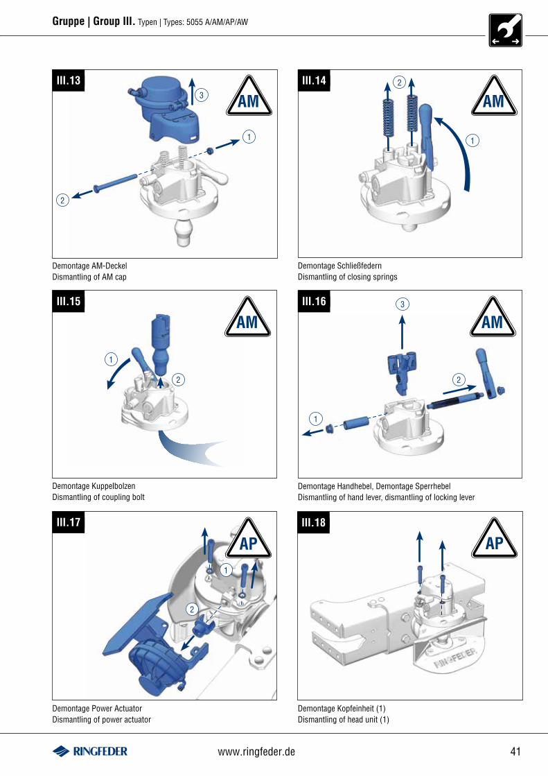
Gruppe | Group III. Typen | Types: 5055 A/AM/AP/AW
III.13
Demontage AM-DeckelDismantling of AM cap
1
2
3
Demontage SchließfedernDismantling of closing springs
III.14
1
2
AM AM
1
III.15
2
Demontage KuppelbolzenDismantling of coupling bolt
III.16
Demontage Handhebel, Demontage SperrhebelDismantling of hand lever, dismantling of locking lever
1
2
3
AM AM
APIII.17
1
2
III.18
AP
Demontage Power ActuatorDismantling of power actuator
Demontage Kopfeinheit (1)Dismantling of head unit (1)
42 Inspection 01/2012
Gruppe | Group III. Typen | Types: 5055 A/AM/AP/AW
III.19 III.20
1
1
2
2
III.21
2
1
3III.22
1
2
AP
Demontage Kopfeinheit (2)Dismantling of head unit (2)
AP
Demontage RückstellfederDismantling of return springs
AP
Demontage AP-DeckelDismantling of AP cap
AP
Demontage SchließfedernDismantling of closing springs
1
III.23
2
Demontage KuppelbolzenDismantling of coupling bolt
III.24
Demontage Handhebel, Demontage SperrhebelDismantling of hand lever, dismantling of locking lever
1
2
3
AP AP
43www.ringfeder.de
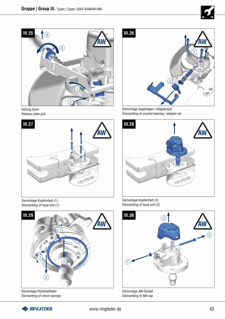
Gruppe | Group III. Typen | Types: 5055 A/AM/AP/AW
III.25
1
3
2
4
AW1
AWIII.26
III.27
Demontage Kopfeinheit (1)Dismantling of head unit (1)
III.28
Demontage Kopfeinheit (2)Dismantling of head unit (2)
AW AW
III.29
1
1
2
2
Demontage RückstellfederDismantling of return springs
III.30
2
1
3
Demontage AW-DeckelDismantling of AW cap
AW AW
Seilzug lösenRelease cable pull
Demontage Gegenlager-/ AdaptersatzDismantling of counter-bearing / adapter set
2
44 Inspection 01/2012
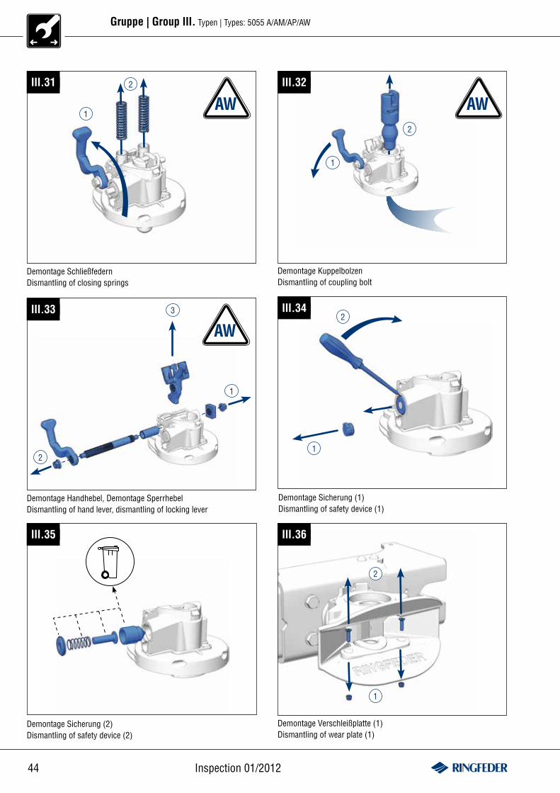
Gruppe | Group III. Typen | Types: 5055 A/AM/AP/AW
III.31
1
2
Demontage SchließfedernDismantling of closing springs
1
III.32
2
Demontage KuppelbolzenDismantling of coupling bolt
III.33
Demontage Handhebel, Demontage SperrhebelDismantling of hand lever, dismantling of locking lever
1
2
3
AW AW
AWIII.34
1
2
Demontage Sicherung (1)Dismantling of safety device (1)
III.35
Demontage Sicherung (2)Dismantling of safety device (2)
III.36
Demontage Verschleißplatte (1)Dismantling of wear plate (1)
1
2
45www.ringfeder.de
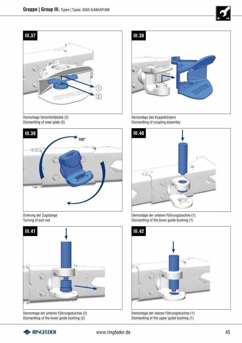
Gruppe | Group III. Typen | Types: 5055 A/AM/AP/AW
III.37
1
2
Demontage Verschleißplatte (2)Dismantling of wear plate (2)
III.38
Demontage des KuppelkörpersDismantling of coupling assembly
180°III.39 III.40
Drehung der ZugstangeTurning of pull rod
Demontage der unteren Führungsbuchse (1)Dismantling of the lower guide bushing (1)
III.41
Demontage der unteren Führungsbuchse (2)Dismantling of the lower guide bushing (2)
III.42
Demontage der oberen Führungsbuchse (1)Dismantling of the upper guide bushing (1)
46 Inspection 01/2012
Gruppe | Group III. Typen | Types: 5055 A/AM/AP/AW
III.43
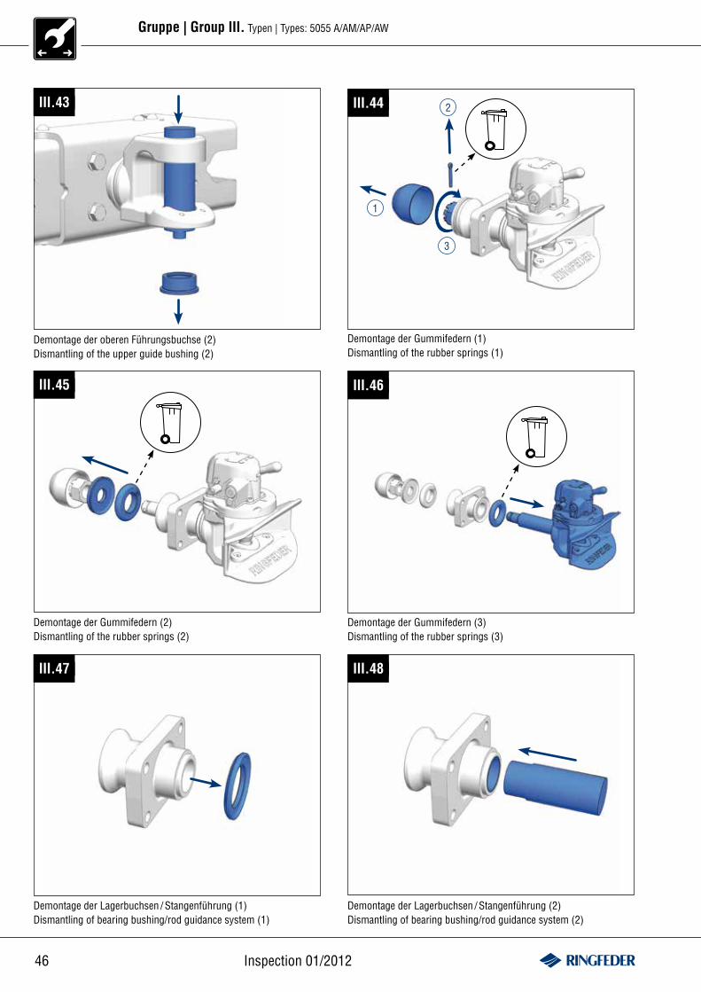
Demontage der oberen Führungsbuchse (2)Dismantling of the upper guide bushing (2)
III.44
3
1
2
Demontage der Gummifedern (1)Dismantling of the rubber springs (1)
III.45
Demontage der Gummifedern (2)Dismantling of the rubber springs (2)
III.46
Demontage der Gummifedern (3)Dismantling of the rubber springs (3)
III.47
Demontage der Lagerbuchsen / Stangenführung (1)Dismantling of bearing bushing/rod guidance system (1)
III.48
Demontage der Lagerbuchsen / Stangenführung (2)Dismantling of bearing bushing/rod guidance system (2)
47www.ringfeder.de
Gruppe | Group III. Typen | Types: 5055 A/AM/AP/AW
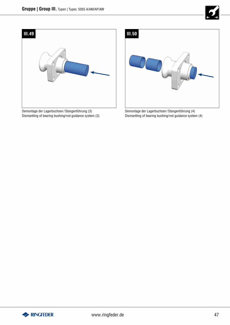
III.49
Demontage der Lagerbuchsen / Stangenführung (3)Dismantling of bearing bushing/rod guidance system (3)
III.50
Demontage der Lagerbuchsen / Stangenführung (4)Dismantling of bearing bushing/rod guidance system (4)

48 Inspection 01/2012
Gruppe | Group III. Typen | Types: 5055 A/AM/AP/AW
Montage der Lagerbuchsen / Stangenführung (1)Fitting of bearing bushing/rod guidance system (1)
III.51
! 1
2
Montage der Lagerbuchsen / Stangenführung (2)Fitting of bearing bushing/rod guidance system (2)
III.52
III.53
Montage der Lagerbuchsen / Stangenführung (3)Fitting of bearing bushing/rod guidance system (3)
III.54
Montage der Lagerbuchsen / Stangenführung (4)Fitting of bearing bushing/rod guidance system (4)
III.55
Montage der Lagerbuchsen / Stangenführung (5)Fitting of bearing bushing/rod guidance system (5)
III.56
Montage der Gummifedern (1)Fitting of the rubber springs (1)
49www.ringfeder.de
Gruppe | Group III. Typen | Types: 5055 A/AM/AP/AW
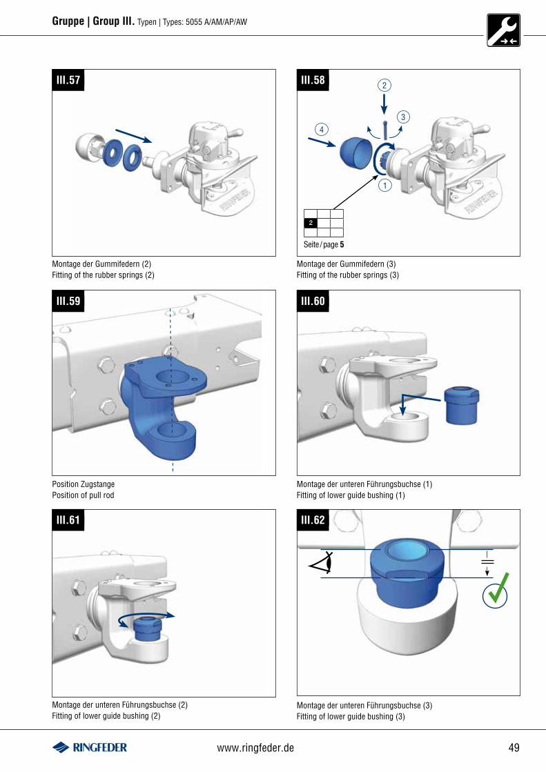
Montage der Gummifedern (2)Fitting of the rubber springs (2)
III.57
Seite /page 5
III.58 2
4
1
2
3
Montage der Gummifedern (3)Fitting of the rubber springs (3)
III.59
Position ZugstangePosition of pull rod
III.60
Montage der unteren Führungsbuchse (1)Fitting of lower guide bushing (1)
Montage der unteren Führungsbuchse (2)Fitting of lower guide bushing (2)
III.61
Montage der unteren Führungsbuchse (3)Fitting of lower guide bushing (3)
III.62
50 Inspection 01/2012
Gruppe | Group III. Typen | Types: 5055 A/AM/AP/AW
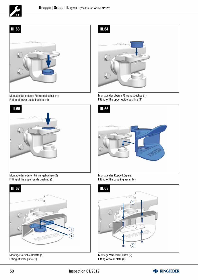
III.63 III.64
Montage der unteren Führungsbuchse (4)Fitting of lower guide bushing (4)
Montage der oberen Führungsbuchse (1)Fitting of the upper guide bushing (1)
III.65
Montage der oberen Führungsbuchse (2)Fitting of the upper guide bushing (2)
III.68
Montage Verschleißplatte (2)Fitting of wear plate (2)
2
1
III.67
2
1
Montage Verschleißplatte (1)Fitting of wear plate (1)
III.66
Montage des KuppelkörpersFitting of the coupling assembly
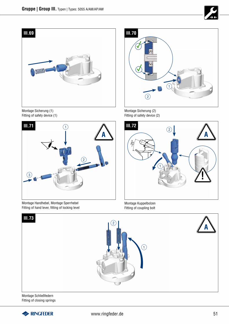
51www.ringfeder.de
Gruppe | Group III. Typen | Types: 5055 A/AM/AP/AW
III.69
Montage Sicherung (1)Fitting of safety device (1)
Montage Sicherung (2)Fitting of safety device (2)
III.70
2
1
III.71
Montage Handhebel, Montage SperrhebelFitting of hand lever, fitting of locking level
3
2
1
A~2
5°
III.72
!1
2
Montage KuppelbolzenFitting of coupling bolt
Montage SchließfedernFitting of closing springs
III.73
1
2A
A
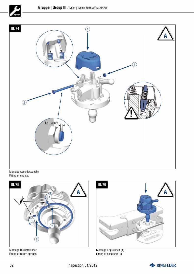
52 Inspection 01/2012
Gruppe | Group III. Typen | Types: 5055 A/AM/AP/AW
III.75
A1
1
2
2
Montage RückstellfederFitting of return springs
Montage Kopfeinheit (1)Fitting of head unit (1)
III.76
A
III.74 1
3
2
Montage AbschlussdeckelFitting of end cap
A
!1,5 – 3 mm
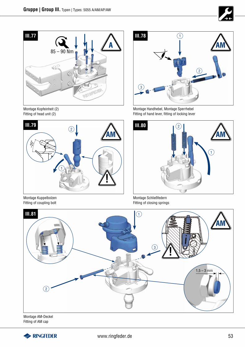
53www.ringfeder.de
Gruppe | Group III. Typen | Types: 5055 A/AM/AP/AW
Montage Kopfeinheit (2)Fitting of head unit (2)
III.77
AIII.78
Montage Handhebel, Montage SperrhebelFitting of hand lever, fitting of locking lever
3
2
1
AM
~25°
III.79
!1
2
Montage KuppelbolzenFitting of coupling bolt
AM
Montage SchließfedernFitting of closing springs
III.80
1
2
AM
85 – 90 Nm
III.81 1
3
2
Montage AM-DeckelFitting of AM cap
AM
!1,5 – 3 mm
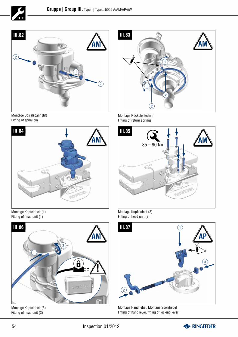
54 Inspection 01/2012
Gruppe | Group III. Typen | Types: 5055 A/AM/AP/AW
III.87
Montage Handhebel, Montage SperrhebelFitting of hand lever, fitting of locking lever
3
2
1
AP
III.83
1
1
2
2
Montage RückstellfedernFitting of return springs
AMIII.82
AM
2
2
1
Montage SpiralspannstiftFitting of spiral pin
III.84
AM
Montage Kopfeinheit (1)Fitting of head unit (1)
III.85
Montage Kopfeinheit (2)Fitting of head unit (2)
AM85 – 90 Nm
III.86
AM
!
2
1
Montage Kopfeinheit (3)Fitting of head unit (3)
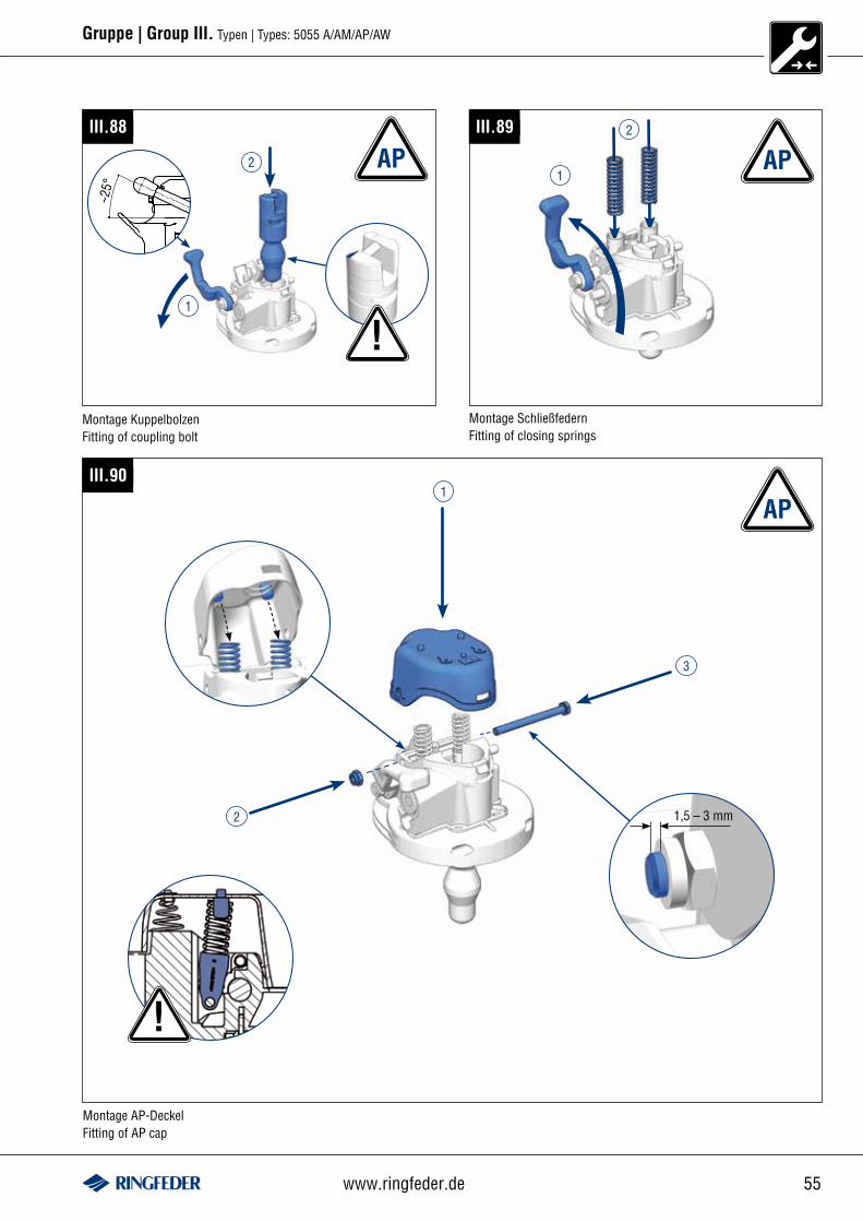
55www.ringfeder.de
Gruppe | Group III. Typen | Types: 5055 A/AM/AP/AW
III.89
1
2
AP
Montage SchließfedernFitting of closing springs
~25°
III.88
!1
2
Montage KuppelbolzenFitting of coupling bolt
AP
III.901
3
2
Montage AP-DeckelFitting of AP cap
AP
!
1,5 – 3 mm
56 Inspection 01/2012
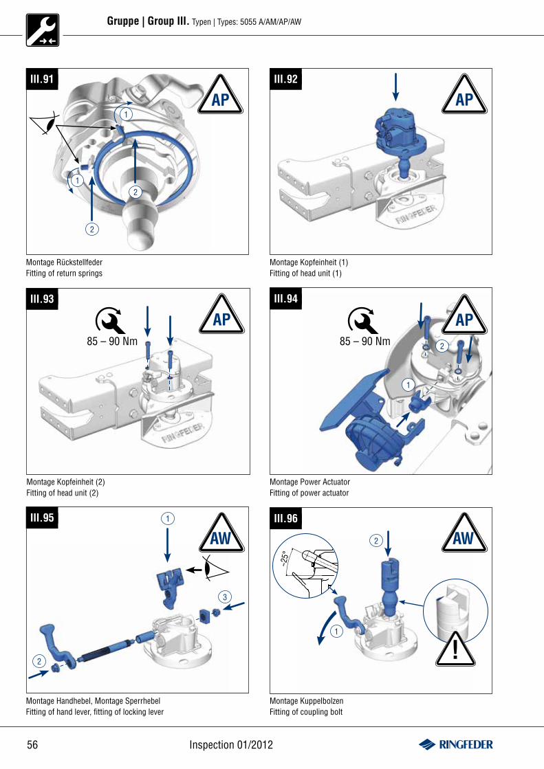
Gruppe | Group III. Typen | Types: 5055 A/AM/AP/AW
III.91
1
1
2
2
AP
Montage RückstellfederFitting of return springs
III.92
AP
Montage Kopfeinheit (1)Fitting of head unit (1)
APIII.94
2
1
III.93
AP
Montage Power ActuatorFitting of power actuator
Montage Kopfeinheit (2)Fitting of head unit (2)
85 – 90 Nm 85 – 90 Nm
III.95
Montage Handhebel, Montage SperrhebelFitting of hand lever, fitting of locking lever
3
2
1
~25°
III.96
!1
2
Montage KuppelbolzenFitting of coupling bolt
AW AW
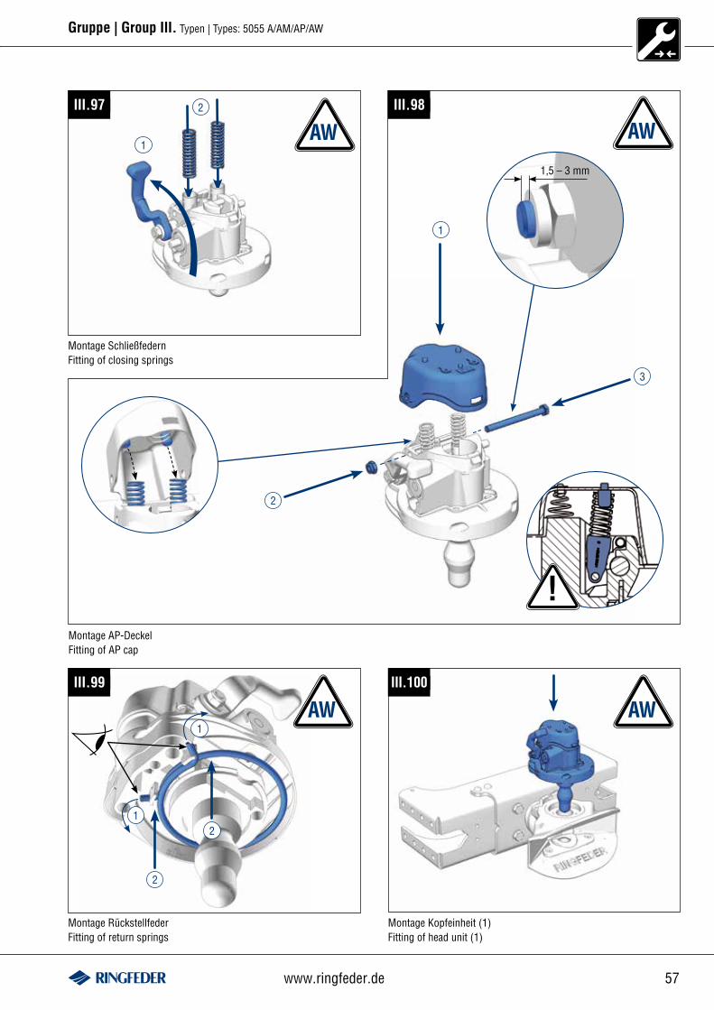
57www.ringfeder.de
Gruppe | Group III. Typen | Types: 5055 A/AM/AP/AW
III.99
1
1
2
2
Montage RückstellfederFitting of return springs
III.100
Montage Kopfeinheit (1)Fitting of head unit (1)
AW AW
III.97
1
2
Montage SchließfedernFitting of closing springs
AWIII.98
1
3
2
Montage AP-DeckelFitting of AP cap
!
1,5 – 3 mm
AW
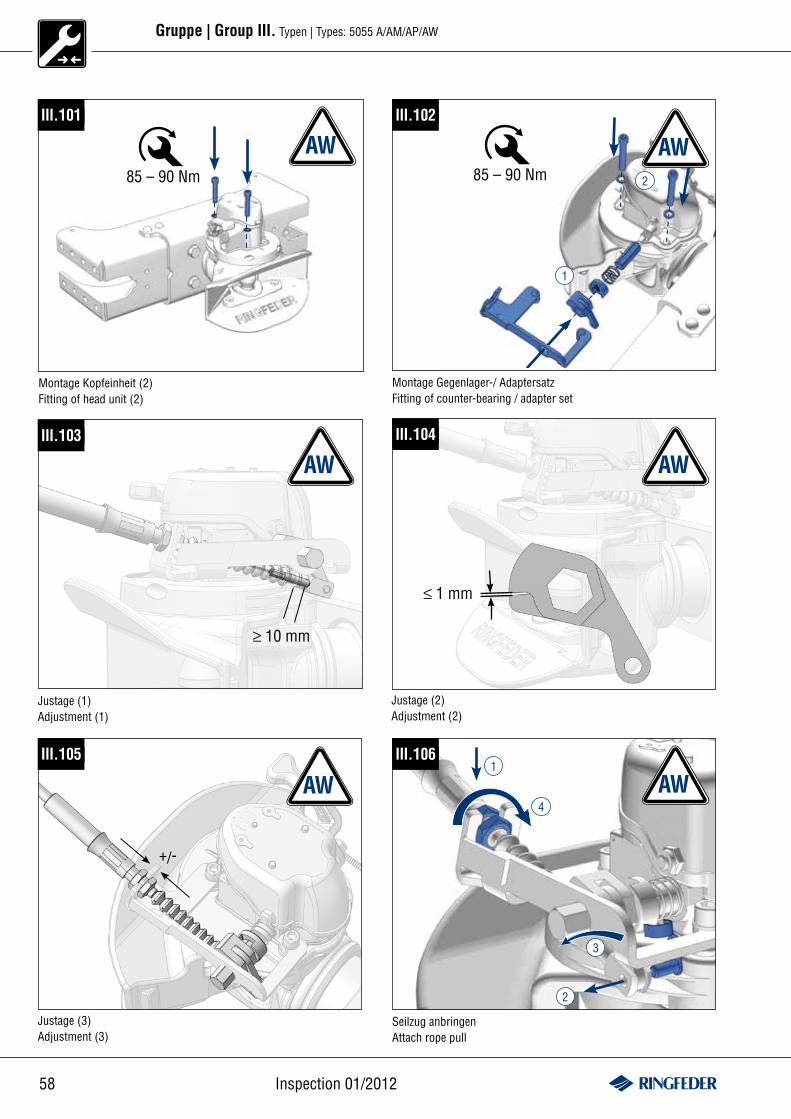
58 Inspection 01/2012
Gruppe | Group III. Typen | Types: 5055 A/AM/AP/AW
III.101
Montage Kopfeinheit (2)Fitting of head unit (2)
85 – 90 Nm
AW2
AWIII.102
Montage Gegenlager-/ AdaptersatzFitting of counter-bearing / adapter set
85 – 90 Nm
1
III.106
3
4
2
1
AW
Seilzug anbringenAttach rope pull
III.103
≥ 10 mm
AWIII.104
AW
≤ 1 mm
Justage (1)Adjustment (1)
Justage (2)Adjustment (2)
+/-
Justage (3)Adjustment (3)
AWIII.105
59www.ringfeder.de
Gruppe | Group III. Typen | Types: 5055 A/AM/AP/AW
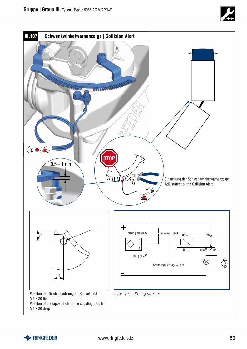
III.107
Schaltplan | Wiring scheme
Schwenkwinkelwarnanzeige | Collision Alert
0.5 – 1 mm
Position der Gewindebohrung im Kuppelmaul M8 x 20 tief Position of the tapped hole in the coupling mouth M8 x 20 deep
Spannung | Voltage = 24 V
blau | blue
braun | brown schwarz | black
STOP
Einstellung der SchwenkwinkelwarnanzeigeAdjustment of the Collision Alert
60 Inspection 01/2012
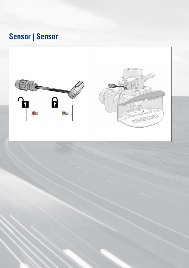
Sensor | Sensor
61www.ringfeder.de
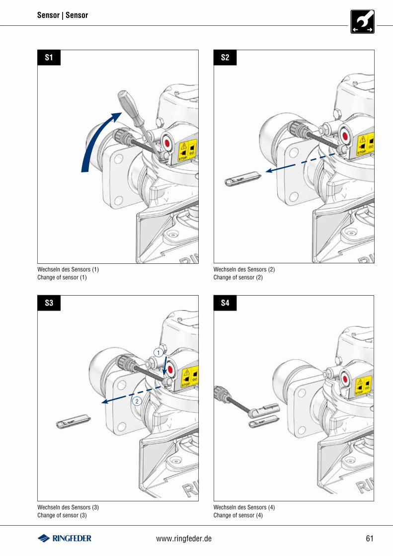
Sensor | Sensor
Wechseln des Sensors (1) Change of sensor (1)
Wechseln des Sensors (2) Change of sensor (2)
Wechseln des Sensors (3) Change of sensor (3)
Wechseln des Sensors (4) Change of sensor (4)
S1 S2
S3 S4
1
2
62 Inspection 01/2012
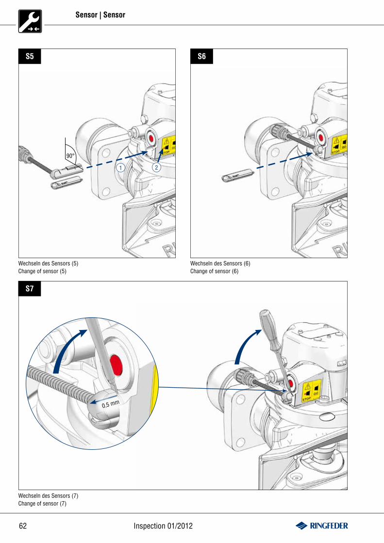
Sensor | Sensor
Wechseln des Sensors (5) Change of sensor (5)
Wechseln des Sensors (7) Change of sensor (7)
90°
S5 S6
Wechseln des Sensors (6) Change of sensor (6)
0,5 mm
S7
1 2
63www.ringfeder.de
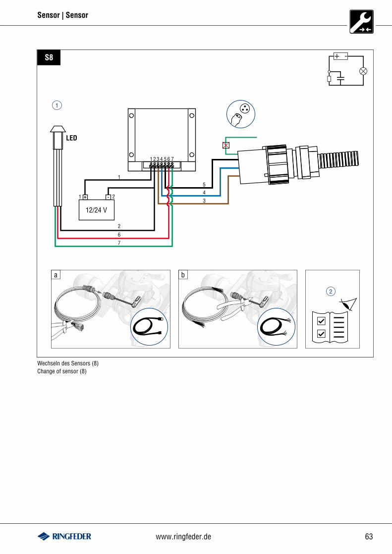
Sensor | Sensor
LED
12/24 V
1 2 3 4 5 6 7
3
45
1
1 + -
6
7
2
2
ba
S8
Wechseln des Sensors (8) Change of sensor (8)
+ -
1
2

w w w . r i n g f e d e r . d e
Montage, Bedienung, WartungInstallation, Operation, Maintenancewww.ringfeder.de
RINGFEDER® 86/G 110, 4040, 404580/G3-G5, 5050
RINGFEDER® 5055 A, B, AM, AP, AW
RINGFEDER® 4040 AM, 4045 AM5050 AM, 5055 AM
Sensoreinbau · Fitting sensor
VBG GROUP TRUCK EQUIPMENT GMBHE-Mail: [email protected]