Embed Size (px)
Citation preview

AL4021 Formaldehyde-Monitor
Instruction Manual

AL4021 Safety Formaldehyde-Monitor
2 IM_AL4021_Rev.2.2.doc
AERO LASER Gesellschaft für Gasanalytik mbH Unterfeldstr. 12 D-82467 Garmisch-Partenkirchen Germany Tel: + 49 (0)8821 94386-0 Fax: + 49 (0)8821 94386-18 E-Mail: [email protected] www.aero-laser.de
AL4021 Formaldehyde-Monitor Safety
IM_AL4021_Rev.2.2.doc 3
Contents 1 Safety.................................................................................................................. 5
1.1 Safety Conventions ...................................................................................... 5 1.2 Health and Safety......................................................................................... 5 1.3 Product Disposal .......................................................................................... 5 1.4 Electrical Safety............................................................................................ 5 1.5 Service and Repairs ..................................................................................... 6 1.6 Chemicals .................................................................................................... 6
2 Introduction ....................................................................................................... 7 2.1 Necessary Items........................................................................................... 7 2.2 Principle of Operation................................................................................... 7 2.3 Chemical Compartment................................................................................ 8
2.3.1 Stripper ................................................................................................. 9 2.3.2 Reactor ................................................................................................. 9 2.3.3 Peristaltic Pump .................................................................................. 10 2.3.4 Mass Flow Controller .......................................................................... 10 2.3.5 Permeation Source (optional).............................................................. 10
2.4 Electronics Compartment ........................................................................... 10 2.4.1 Fluorimeter .......................................................................................... 11 2.4.2 UV-LED............................................................................................... 11
2.5 Specifications ............................................................................................. 11 2.6 Consumptions ............................................................................................ 12 2.7 Integrated data storage .............................................................................. 12
3 Getting Started ................................................................................................ 13 3.1 Unpacking the Instrument .......................................................................... 13 3.2 Installing Software ...................................................................................... 13
3.2.1 SqeezeDat .......................................................................................... 13 3.2.2 Driver .................................................................................................. 14
3.3 Preparation of Solutions ............................................................................. 14 3.3.1 Necessary Chemicals ......................................................................... 14 3.3.2 Necessary Items ................................................................................. 14 3.3.3 Hantzsch Reagent............................................................................... 15 3.3.4 Stripping Solution ................................................................................ 15 3.3.5 Standard Stock Solution...................................................................... 15 3.3.6 Standard Solution................................................................................ 15
4 Installation ....................................................................................................... 16 4.1 Mounting the Instrument............................................................................. 16 4.2 Electrical Connections................................................................................ 17 4.3 Testing ....................................................................................................... 17
5 Operation ......................................................................................................... 18 5.1 Touch Screen Controls: General layout ..................................................... 18 5.2 Menu: Data................................................................................................. 19 5.3 Menu: Status .............................................................................................. 21 5.4 Menu: Calibrate.......................................................................................... 23 5.5 Menu: Graph .............................................................................................. 25 5.6 Menu: Setup............................................................................................... 27
5.6.1 Setup: Calibration................................................................................ 27 5.6.2 Setup: AutoSequence ......................................................................... 31 5.6.3 Setup: File Options.............................................................................. 34
AL4021 Safety Formaldehyde-Monitor
4 IM_AL4021_Rev.2.2.doc
5.6.4 Setup: Graph....................................................................................... 36 5.6.5 Setup: System..................................................................................... 37 5.6.6 Setup: Admin....................................................................................... 40 5.6.7 Setup: Calc. Standard ......................................................................... 42
5.7 Menu: Standby ........................................................................................... 44 5.8 SqeezeDat ................................................................................................. 45
5.8.1 Installation........................................................................................... 45 5.8.2 Setup................................................................................................... 47 5.8.3 Data Aquisition .................................................................................... 52 5.8.4 Data Export ......................................................................................... 53
5.9 Start-Up Procedure .................................................................................... 55 5.10 Calibration/Zeroing ..................................................................................... 56
5.10.1 Measuring Stripper Speed (if no Liquid Flow Meter is installed).......... 56 5.10.2 Liquid Calibration ................................................................................ 56 5.10.3 Gas Calibration ................................................................................... 57
5.11 Measurement ............................................................................................. 57 5.12 Auto Mode.................................................................................................. 58 5.13 Switch Off Procedure ................................................................................. 58
6 Maintenance..................................................................................................... 59 6.1 Cleaning ..................................................................................................... 59 6.2 Tubes and Replacement ............................................................................ 59 6.3 Daily ........................................................................................................... 60 6.4 Weekly ....................................................................................................... 60 6.5 Monthly....................................................................................................... 60 6.6 Yearly ......................................................................................................... 60
7 Troubleshooting .............................................................................................. 62 7.1 System is Not Booting ................................................................................ 62 7.2 No Lamp Signal.......................................................................................... 62 7.3 Peristaltic Pump ......................................................................................... 62
7.3.1 Pump does not rotate.......................................................................... 62 7.4 Bubbles in Cell ........................................................................................... 62
7.4.1 If debubbler operates normally............................................................ 62 7.4.2 If bubbles are too large for debubbler ................................................. 62 7.4.3 If bubbles are irregular in size ............................................................. 63
7.5 Air Flow Rate Too Low ............................................................................... 63 7.6 “Liquid Trap Error” ...................................................................................... 63 7.7 Calibration Not Possible ............................................................................. 63
7.7.1 Not possible due to unstable signal (Stabilisation Timeout) ................ 63 7.7.2 Unable to regulate HV (Regulation Timeout) ...................................... 64
7.8 No Connection to PC.................................................................................. 64 8 Appendix .......................................................................................................... 65
8.1 Analog Output (optional) ............................................................................ 65 8.2 Digital Output ............................................................................................. 65
8.2.1 Remote Commands ............................................................................ 66 8.2.2 Error Messages................................................................................... 67
8.3 Peristaltic Pump Speeds ............................................................................ 68 8.4 Definition of the Status Flag ....................................................................... 68
AL4021 Formaldehyde-Monitor Safety
IM_AL4021_Rev.2.2.doc 5
1 Safety
1.1 Safety Conventions
Warning:
A warning indicates information or instructions that, if not met, can damage the in-strument or even cause serious personal injury or death!
Note:
A note indicates important information or instructions which should be considered for operating the instrument!
This symbol indicates the need for protective eyewear!
This symbol indicates the need for protective hand wear!
1.2 Health and Safety
Warning:
Read the manual before installing and operating the instrument! Observe warning labels!
1.3 Product Disposal In conformity with European local and national regulations, electrical equipment us-ers must now return old or end-of-life equipment to the manufacturer for disposal.
1.4 Electrical Safety There are lethal voltages inside the instrument. Always disconnect AC line power before servicing the system.
AL4021 Safety Formaldehyde-Monitor
6 IM_AL4021_Rev.2.2.doc
1.5 Service and Repairs Only personnel from Aero-Laser, its approved representatives and trained users are authorized to repair or maintain the instrument. Any attempt of unqualified persons to repair or maintain the instrument, can cause damage to the instrument and severe injuries.
Note:
Any attempt of unauthorized personnel to repair or maintain the instrument will cause the loss of warranty!
1.6 Chemicals Some of the chemicals are hazardous. Read the material safety data sheets carefully and always wear your personal protective equipment.
Warning:
Store chemicals away from heat and protect them from temperature extremes! Always review the material safety data sheet prior to handling chemicals!
AL4021 Formaldehyde-Monitor Introduction
IM_AL4021_Rev.2.2.doc 7
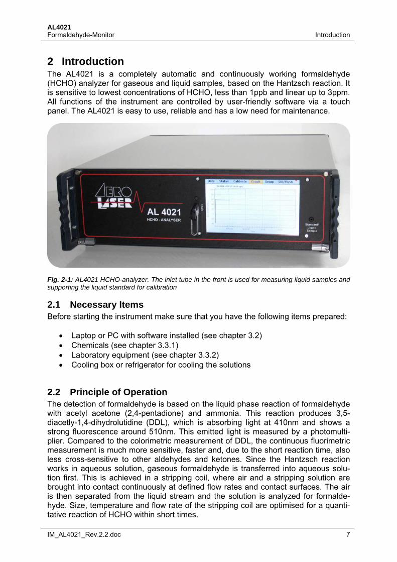
2 Introduction The AL4021 is a completely automatic and continuously working formaldehyde (HCHO) analyzer for gaseous and liquid samples, based on the Hantzsch reaction. It is sensitive to lowest concentrations of HCHO, less than 1ppb and linear up to 3ppm. All functions of the instrument are controlled by user-friendly software via a touch panel. The AL4021 is easy to use, reliable and has a low need for maintenance.
Fig. 2-1: AL4021 HCHO-analyzer. The inlet tube in the front is used for measuring liquid samples and supporting the liquid standard for calibration
2.1 Necessary Items Before starting the instrument make sure that you have the following items prepared:
Laptop or PC with software installed (see chapter 3.2) Chemicals (see chapter 3.3.1) Laboratory equipment (see chapter 3.3.2) Cooling box or refrigerator for cooling the solutions
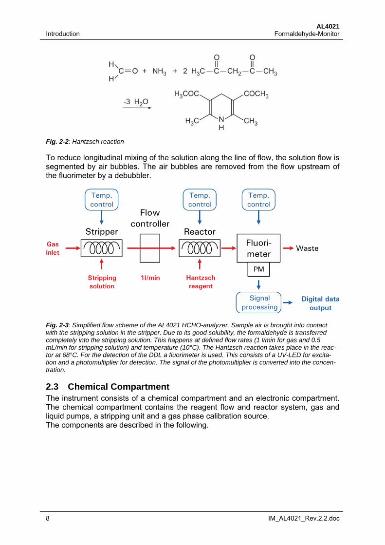
2.2 Principle of Operation The detection of formaldehyde is based on the liquid phase reaction of formaldehyde with acetyl acetone (2,4-pentadione) and ammonia. This reaction produces 3,5-diacetly-1,4-dihydrolutidine (DDL), which is absorbing light at 410nm and shows a strong fluorescence around 510nm. This emitted light is measured by a photomulti-plier. Compared to the colorimetric measurement of DDL, the continuous fluorimetric measurement is much more sensitive, faster and, due to the short reaction time, also less cross-sensitive to other aldehydes and ketones. Since the Hantzsch reaction works in aqueous solution, gaseous formaldehyde is transferred into aqueous solu-tion first. This is achieved in a stripping coil, where air and a stripping solution are brought into contact continuously at defined flow rates and contact surfaces. The air is then separated from the liquid stream and the solution is analyzed for formalde-hyde. Size, temperature and flow rate of the stripping coil are optimised for a quanti-tative reaction of HCHO within short times.
AL4021 Introduction Formaldehyde-Monitor
8 IM_AL4021_Rev.2.2.doc
Fig. 2-2: Hantzsch reaction
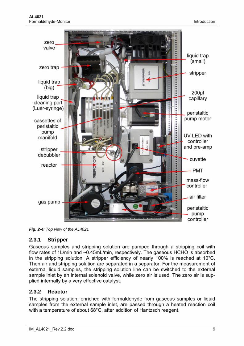
To reduce longitudinal mixing of the solution along the line of flow, the solution flow is segmented by air bubbles. The air bubbles are removed from the flow upstream of the fluorimeter by a debubbler.
PM
Stripper
Flowcontroller
Fluori-meter
Reactor
Waste
Strippingsolution
Gas inlet
Temp.control
Temp.control
Temp.control
Signalprocessing
Digital dataoutput
Hantzschreagent
1l/min
Fig. 2-3: Simplified flow scheme of the AL4021 HCHO-analyzer. Sample air is brought into contact with the stripping solution in the stripper. Due to its good solubility, the formaldehyde is transferred completely into the stripping solution. This happens at defined flow rates (1 l/min for gas and 0.5 mL/min for stripping solution) and temperature (10°C). The Hantzsch reaction takes place in the reac-tor at 68°C. For the detection of the DDL a fluorimeter is used. This consists of a UV-LED for excita-tion and a photomultiplier for detection. The signal of the photomultiplier is converted into the concen-tration.
2.3 Chemical Compartment The instrument consists of a chemical compartment and an electronic compartment. The chemical compartment contains the reagent flow and reactor system, gas and liquid pumps, a stripping unit and a gas phase calibration source. The components are described in the following.
AL4021 Formaldehyde-Monitor Introduction
IM_AL4021_Rev.2.2.doc 9
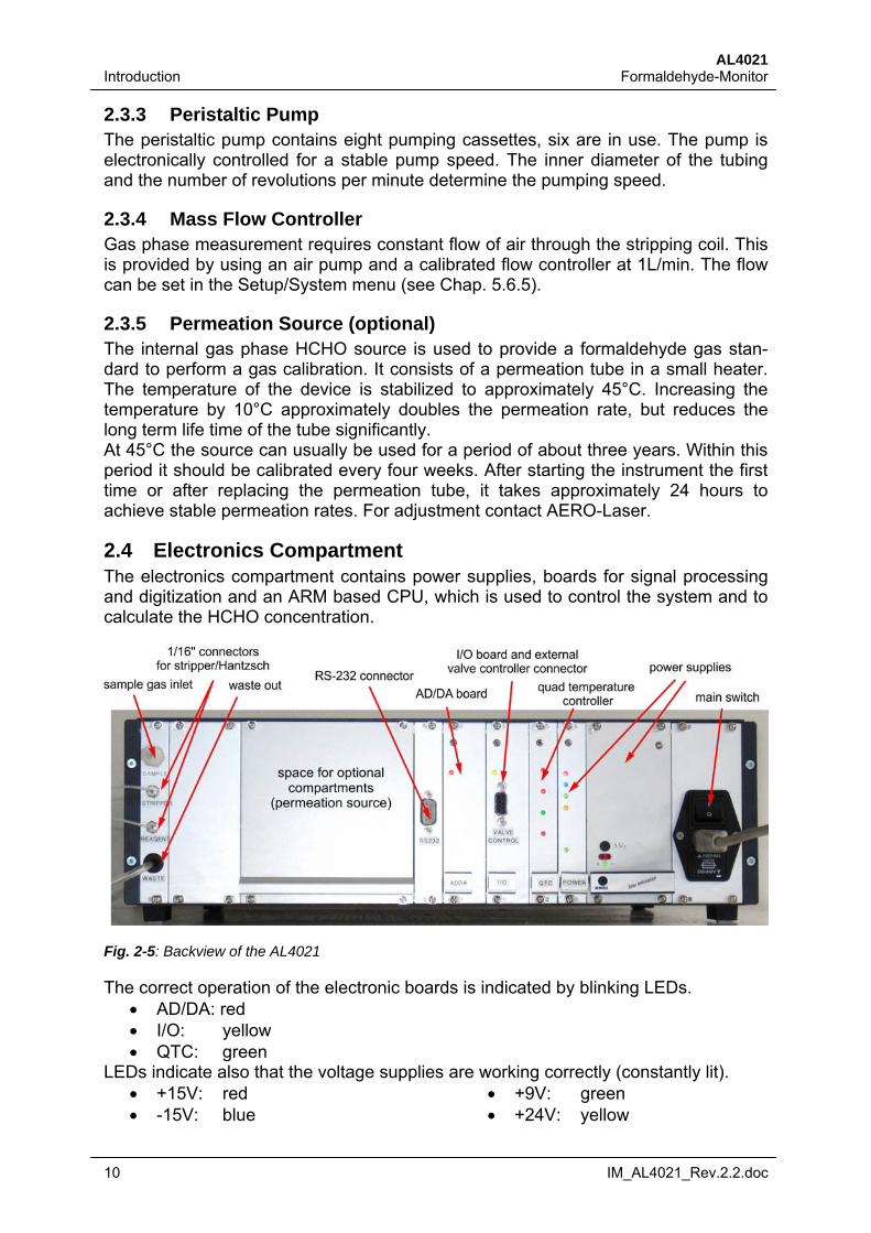
Fig. 2-4: Top view of the AL4021
2.3.1 Stripper Gaseous samples and stripping solution are pumped through a stripping coil with flow rates of 1L/min and ~0.45mL/min, respectively. The gaseous HCHO is absorbed in the stripping solution. A stripper efficiency of nearly 100% is reached at 10°C. Then air and stripping solution are separated in a separator. For the measurement of external liquid samples, the stripping solution line can be switched to the external sample inlet by an internal solenoid valve, while zero air is used. The zero air is sup-plied internally by a very effective catalyst.
2.3.2 Reactor The stripping solution, enriched with formaldehyde from gaseous samples or liquid samples from the external sample inlet, are passed through a heated reaction coil with a temperature of about 68°C, after addition of Hantzsch reagent.
AL4021 Introduction Formaldehyde-Monitor
10 IM_AL4021_Rev.2.2.doc
2.3.3 Peristaltic Pump The peristaltic pump contains eight pumping cassettes, six are in use. The pump is electronically controlled for a stable pump speed. The inner diameter of the tubing and the number of revolutions per minute determine the pumping speed.
2.3.4 Mass Flow Controller Gas phase measurement requires constant flow of air through the stripping coil. This is provided by using an air pump and a calibrated flow controller at 1L/min. The flow can be set in the Setup/System menu (see Chap. 5.6.5).
2.3.5 Permeation Source (optional) The internal gas phase HCHO source is used to provide a formaldehyde gas stan-dard to perform a gas calibration. It consists of a permeation tube in a small heater. The temperature of the device is stabilized to approximately 45°C. Increasing the temperature by 10°C approximately doubles the permeation rate, but reduces the long term life time of the tube significantly. At 45°C the source can usually be used for a period of about three years. Within this period it should be calibrated every four weeks. After starting the instrument the first time or after replacing the permeation tube, it takes approximately 24 hours to achieve stable permeation rates. For adjustment contact AERO-Laser.
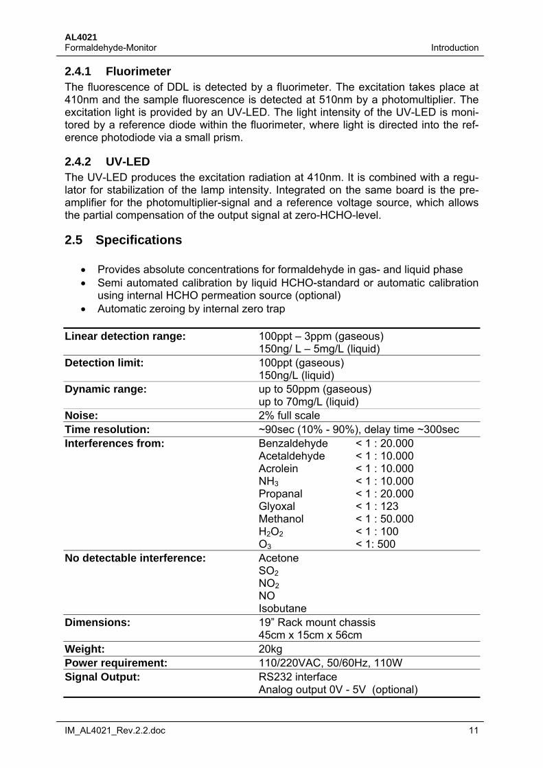
2.4 Electronics Compartment The electronics compartment contains power supplies, boards for signal processing and digitization and an ARM based CPU, which is used to control the system and to calculate the HCHO concentration.
Fig. 2-5: Backview of the AL4021
The correct operation of the electronic boards is indicated by blinking LEDs. AD/DA: red I/O: yellow QTC: green
LEDs indicate also that the voltage supplies are working correctly (constantly lit). +15V: red -15V: blue
+9V: green +24V: yellow
AL4021 Formaldehyde-Monitor Introduction
IM_AL4021_Rev.2.2.doc 11
2.4.1 Fluorimeter The fluorescence of DDL is detected by a fluorimeter. The excitation takes place at 410nm and the sample fluorescence is detected at 510nm by a photomultiplier. The excitation light is provided by an UV-LED. The light intensity of the UV-LED is moni-tored by a reference diode within the fluorimeter, where light is directed into the ref-erence photodiode via a small prism.
2.4.2 UV-LED The UV-LED produces the excitation radiation at 410nm. It is combined with a regu-lator for stabilization of the lamp intensity. Integrated on the same board is the pre-amplifier for the photomultiplier-signal and a reference voltage source, which allows the partial compensation of the output signal at zero-HCHO-level.
2.5 Specifications
Provides absolute concentrations for formaldehyde in gas- and liquid phase Semi automated calibration by liquid HCHO-standard or automatic calibration
using internal HCHO permeation source (optional) Automatic zeroing by internal zero trap
Linear detection range: 100ppt – 3ppm (gaseous) 150ng/ L – 5mg/L (liquid) Detection limit: 100ppt (gaseous) 150ng/L (liquid) Dynamic range: up to 50ppm (gaseous) up to 70mg/L (liquid) Noise: 2% full scale Time resolution: ~90sec (10% - 90%), delay time ~300sec Interferences from: Benzaldehyde < 1 : 20.000 Acetaldehyde < 1 : 10.000 Acrolein < 1 : 10.000 NH3 < 1 : 10.000 Propanal < 1 : 20.000 Glyoxal < 1 : 123 Methanol < 1 : 50.000 H2O2 < 1 : 100 O3 < 1: 500 No detectable interference: Acetone SO2 NO2 NO Isobutane Dimensions: 19” Rack mount chassis 45cm x 15cm x 56cm Weight: 20kg Power requirement: 110/220VAC, 50/60Hz, 110W Signal Output: RS232 interface Analog output 0V - 5V (optional)
AL4021 Introduction Formaldehyde-Monitor
12 IM_AL4021_Rev.2.2.doc
2.6 Consumptions The consumption of chemicals depends on the speed of the liquid pump. The below mentioned consumptions are estimated for 7 days (24/7 operation) at pump speed “B” (factory setting) Consumption of solutions:
~ 7.5 L stripping solution ~ 3.5 L Hantzsch reagent
Consumption of chemicals:
270g Ammonium Acetate 7mL Acetyl Acetone 9mL Acetic Acid 22.5mL Sulphuric Acid 1mL 37% HCHO solution 11L Water (free of HCHO)
2.7 Integrated data storage The instrument can store the current parameters (concentration, signal, ...) on an USB-stick that is inserted into the USB-slot on the front panel. As default, data is logged every second. The data logging rate can be set to the user's requirement. The file naming and the parameters that are stored can be selected in the Setup/File Op-tions menu (see Chap. 5.6.3).
Warning:
Always stop data logging before the USB-stick is pulled out from the front panel! Removing the USB-stick while data is logged could result in a loss of data and/or a
damage of the USB device.
AL4021 Formaldehyde-Monitor Getting Started
IM_AL4021_Rev.2.2.doc 13
3 Getting Started
3.1 Unpacking the Instrument Open the metal box carefully and lift the contents out. Check if the content of the box is undamaged and conforming to the packing list. After unpacking the instrument, keep the metal box for safe shipping.
Note:
Always ship the instrument in its original packaging to prevent damage!
3.2 Installing Software To log data to a data base, the software SqeezeDat needs to be installed on a re-mote computer. SqeezeDat and other necessary installation packages are provided on the DVD that accompanies the AL4021.
Note:
To install the software you need an administrator account!
3.2.1 SqeezeDat Insert the DVD in your PC or laptop and follow the installation instructions.
Note:
You have to install .NET Framework 1.1 and .NET Framework Update 1.1!
You need a registration key to start the program. Send a screenshot with the cus-tomer name and base key to [email protected]. There is a help file which describes how to set and use SqeezeDat and SqeezeDatExport Further you have to install the SQL Server. For details of the installation see Chap. 5.8.1.
AL4021 Getting Started Formaldehyde-Monitor
14 IM_AL4021_Rev.2.2.doc
3.2.2 Driver As most of the new laptops have no RS232 port, an USB adapter is enclosed. You have to install the driver from the DVD which is packed together with the adapter.
3.3 Preparation of Solutions Reagent solutions can be kept for several weeks if properly stored. The Hantzsch reagent solution has to be stored cool at temperatures between 4°C and 10°C.
Warning:
Read the material safety data sheets carefully and always wear your personal protec-tive equipment!
3.3.1 Necessary Chemicals
Ammonium Acetate (MERCK, Order No. 1.01116.5000) Acetic Acid (100%) (MERCK, Order No. 1.00063.2500) Acetyl Acetone (MERCK, Order No. 1.09600.0100) H2SO4 (95% - 97%) (MERCK, Order No. 1.12080.1000) HCHO solution (37%) (MERCK, Order No. 1.04003.1000) HCHO free water (MERCK, Order No. 1.16754.9010)
Note:
Only use the highest purity grade of chemicals to prepare the solutions!
3.3.2 Necessary Items
Magnetic stirrer Balance (0g - 500g) 2 clean 5L glass bottles with caps 100mL glass flasks 10mL pipette 15mL pipette 10µL – 100µL pipette with tips 100µL – 1000µL pipette with tips
AL4021 Formaldehyde-Monitor Getting Started
IM_AL4021_Rev.2.2.doc 15
3.3.3 Hantzsch Reagent 5 litres are prepared from:
5L cold, HCHO free water 385g Ammonium Acetate 12.5mL Acetic Acid 10mL Acetyl Acetone
Note:
Use cold water to prepare the solutions! Store the water overnight in a refrigerator before preparing the solutions!
Fill 800mL cold, HCHO-free water in a 5L glass bottle. Dissolve 385g Ammonium Acetate in the water. Shake or stir till the Ammonium Acetate is dissolved. Add 12.5mL of Acetic Acid and 10mL Acetyl Acetone. Fill up cold water to 5L. Store the solution cold and prevent HCHO from entering into the bottle. For best results store this solution in a refrigerator for at least 12 hours before using it.
3.3.4 Stripping Solution 5 litres are prepared from:
5L cold, HCHO free water 15mL H2SO4 (95% – 97 %)
Dissolve 15mL of H2SO4 in 5L HCHO-free water
3.3.5 Standard Stock Solution A 10-2 molar standard stock solution is prepared by diluting 1mL 37% HCHO solution to 1L with cold water. The HCHO concentration of the stock solution is determined by titration. This solution has to be kept in a refrigerator and should be titrated on a regular time basis. Under these conditions the solution can be stored for several months.
3.3.6 Standard Solution 10-2 molar stock solution is diluted with stripping solution. Highly diluted solutions of HCHO (10-6 – 10-8 molar) in water are stable only for short time intervals, even if stored in a refrigerator. They always have to be prepared fresh before use.
AL4021 Installation Formaldehyde-Monitor
16 IM_AL4021_Rev.2.2.doc
4 Installation
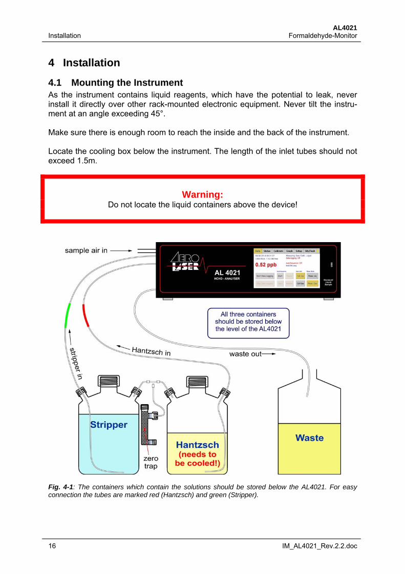
4.1 Mounting the Instrument As the instrument contains liquid reagents, which have the potential to leak, never install it directly over other rack-mounted electronic equipment. Never tilt the instru-ment at an angle exceeding 45°. Make sure there is enough room to reach the inside and the back of the instrument. Locate the cooling box below the instrument. The length of the inlet tubes should not exceed 1.5m.
Warning:
Do not locate the liquid containers above the device!
Fig. 4-1: The containers which contain the solutions should be stored below the AL4021. For easy connection the tubes are marked red (Hantzsch) and green (Stripper).

AL4021 Formaldehyde-Monitor Installation
IM_AL4021_Rev.2.2.doc 17
Note:
After switching on the instrument, the concentrations values are not reliable for at least 45 minutes!
4.2 Electrical Connections Make sure you are using the correct voltage (110V or 220V) marked on the rear side of the instrument. Connect the instrument to an AC power supply.
Warning:
Always run the instrument with the correct voltage! A wrong supply voltage may destroy the instrument!
There are two RS232 serial ports. The first one is on the front of the device labeled “REMOTE” and the other one is on the back panel of the CPU. Use the null modem cable to connect the remote output to your PC or laptop.
4.3 Testing
Warning:
For testing the instrument do not connect it to the solutions!
Open the cover of the instrument Switch on the main power Check if the LED’s of the 24 Volt power supply and 15 Volt power supply glow Check if the lamp voltage reaches 3 Volt Check if the pumps work
AL4021 Operation Formaldehyde-Monitor
18 IM_AL4021_Rev.2.2.doc
5 Operation The AL4021 is operated by the touch screen on the front panel. All operation can also be done remotely via the RS232 interface. See Chapter 8.2.1 for a detailed de-scription of the commands. The touch screen is optimized for the use with fingers directly, but it can also be used with any pen or similar.
Note:
The values shown in the screenshots are only examples!
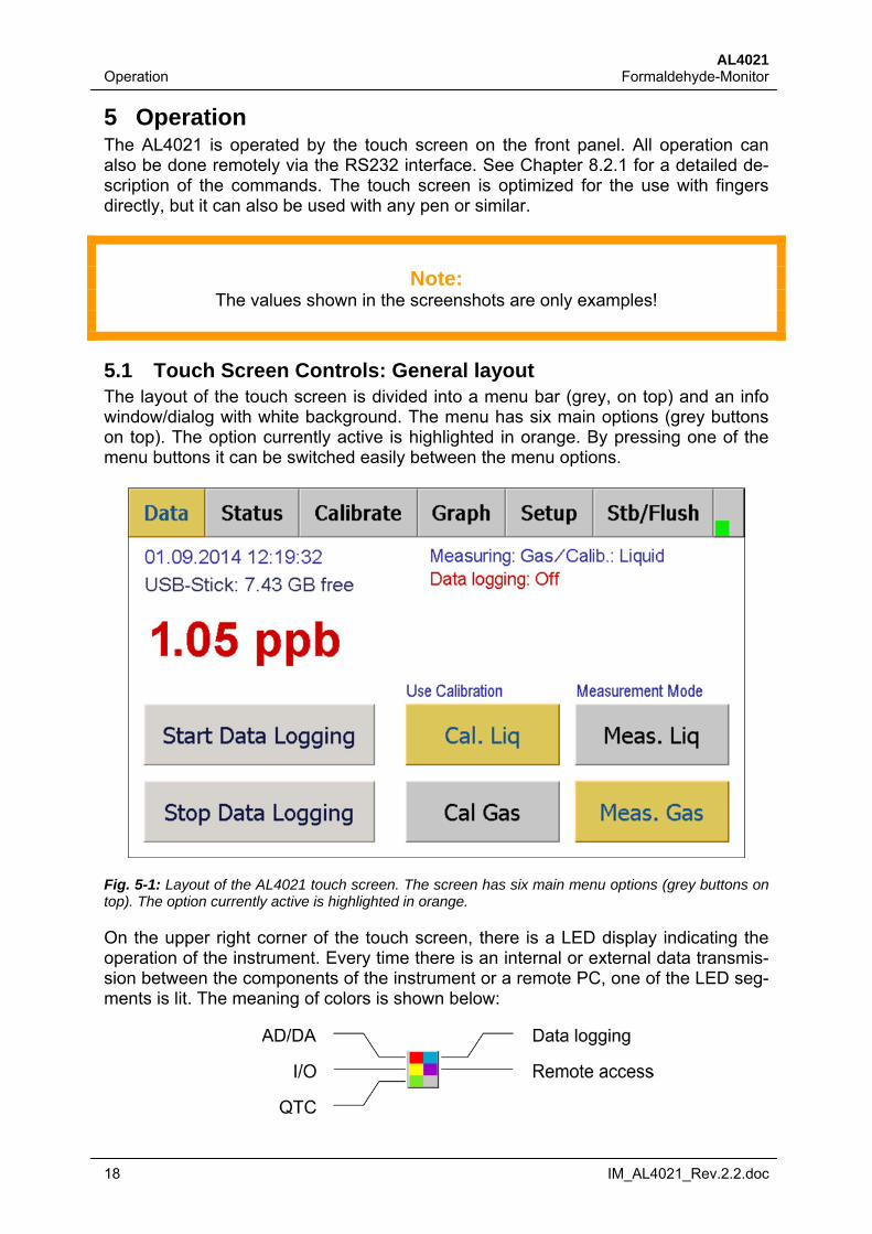
5.1 Touch Screen Controls: General layout The layout of the touch screen is divided into a menu bar (grey, on top) and an info window/dialog with white background. The menu has six main options (grey buttons on top). The option currently active is highlighted in orange. By pressing one of the menu buttons it can be switched easily between the menu options.
Fig. 5-1: Layout of the AL4021 touch screen. The screen has six main menu options (grey buttons on top). The option currently active is highlighted in orange.
On the upper right corner of the touch screen, there is a LED display indicating the operation of the instrument. Every time there is an internal or external data transmis-sion between the components of the instrument or a remote PC, one of the LED seg-ments is lit. The meaning of colors is shown below:
AL4021 Formaldehyde-Monitor Operation
IM_AL4021_Rev.2.2.doc 19
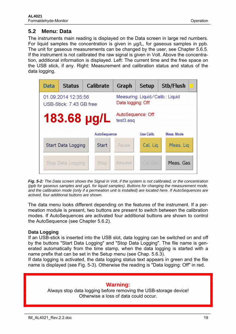
5.2 Menu: Data The instruments main reading is displayed on the Data screen in large red numbers. For liquid samples the concentration is given in µg/L, for gaseous samples in ppb. The unit for gaseous measurements can be changed by the user, see Chapter 5.6.5. If the instrument is not calibrated the raw signal is given in Volt. Above the concentra-tion, additional information is displayed. Left: The current time and the free space on the USB stick, if any. Right: Measurement and calibration status and status of the data logging.
Fig. 5-2: The Data screen shows the Signal in Volt, if the system is not calibrated, or the concentration (ppb for gaseous samples and µg/L for liquid samples). Buttons for changing the measurement mode, and the calibration mode (only if a permeation unit is installed) are located here. If AutoSequences are actived, four additional buttons are shown.
The data menu looks different depending on the features of the instrument. If a per-meation module is present, two buttons are present to switch between the calibration modes. If AutoSequences are activated four additional buttons are shown to control the AutoSequence (see Chapter 5.6.2). Data Logging If an USB-stick is inserted into the USB slot, data logging can be switched on and off by the buttons "Start Data Logging" and "Stop Data Logging". The file name is gen-erated automatically from the time stamp, when the data logging is started with a name prefix that can be set in the Setup menu (see Chap. 5.6.3). If data logging is activated, the data logging status text appears in green and the file name is displayed (see Fig. 5-3). Otherwise the reading is "Data logging: Off" in red.
Warning:
Always stop data logging before removing the USB-storage device! Otherwise a loss of data could occur.
AL4021 Operation Formaldehyde-Monitor
20 IM_AL4021_Rev.2.2.doc
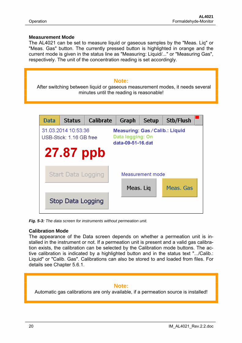
Measurement Mode The AL4021 can be set to measure liquid or gaseous samples by the "Meas. Liq" or "Meas. Gas" button. The currently pressed button is highlighted in orange and the current mode is given in the status line as "Measuring: Liquid/..." or "Measuring Gas", respectively. The unit of the concentration reading is set accordingly.
Note:
After switching between liquid or gaseous measurement modes, it needs several minutes until the reading is reasonable!
Fig. 5-3: The data screen for instruments without permeation unit.
Calibration Mode The appearance of the Data screen depends on whether a permeation unit is in-stalled in the instrument or not. If a permeation unit is present and a valid gas calibra-tion exists, the calibration can be selected by the Calibration mode buttons. The ac-tive calibration is indicated by a highlighted button and in the status text ".../Calib.: Liquid" or "Calib. Gas". Calibrations can also be stored to and loaded from files. For details see Chapter 5.6.1.
Note:
Automatic gas calibrations are only available, if a permeation source is installed!
AL4021 Formaldehyde-Monitor Operation
IM_AL4021_Rev.2.2.doc 21
AutoSequence An automatic sequence of commands is coded into a so-called AutoSequence. For instance, an AutoSequence can automatically schedule calibrations (if a permeation unit is installed) and zeroings during field campaigns. Another example is the auto-matic switching between gas samples, e.g. from test chambers according to the ap-propriate standards (requires a valve controller). Each AutoSequence consists of a series of commands that are executed after each other. Each command can be either started at a fixed time or consecutive after the last command. To each command a wait time can be assigned. The AL4021 has a simple and intuitive editor for those sequences. For a list of the available commands and options and on how to edit AutoSequences see Chapter 5.6.2. The pressing on of the four buttons the following will happen: Start: Resets the internal counter of the AutoSequence. If the AutoSequence has no fixed starting time, it will start immediately. Otherwise it will be scheduled to start with the command having the next fixed starting time after the time of starting. If there is no such command, it will schedule the AutoSequence until the first command of the next day.
Stop: Resets the internal counter of the AutoSequence and terminates it. The in-strument remains in a state according to the last command.
Pause: Interrupts the AutoSequence without resetting its internal counter.
Resume: Resumes an pause AutoSequence at its current position.
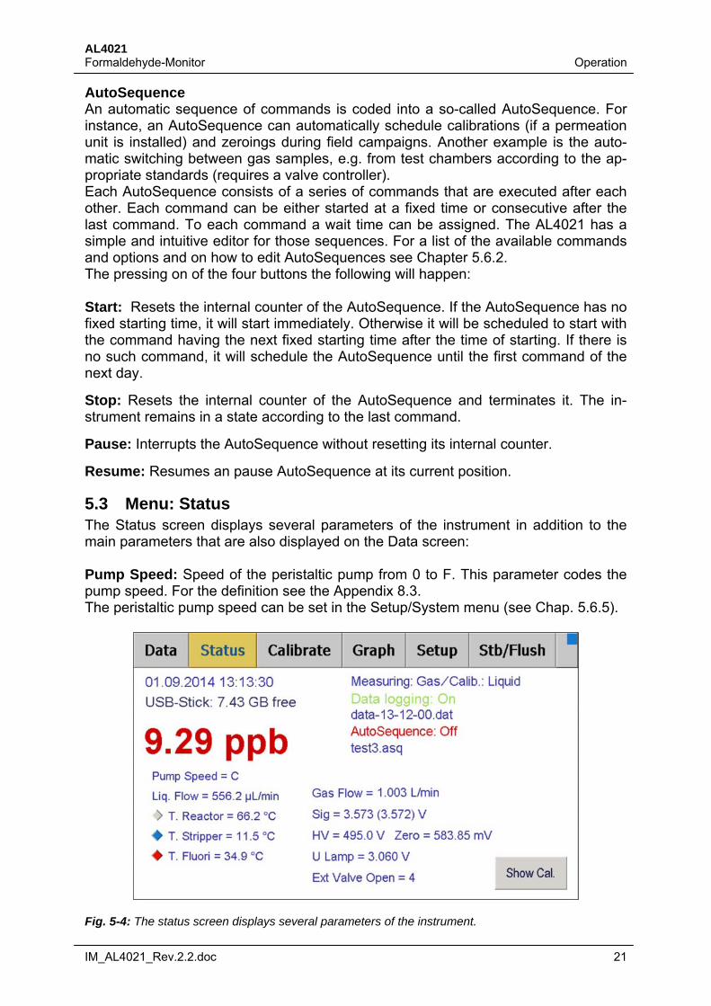
5.3 Menu: Status The Status screen displays several parameters of the instrument in addition to the main parameters that are also displayed on the Data screen: Pump Speed: Speed of the peristaltic pump from 0 to F. This parameter codes the pump speed. For the definition see the Appendix 8.3. The peristaltic pump speed can be set in the Setup/System menu (see Chap. 5.6.5).
Fig. 5-4: The status screen displays several parameters of the instrument.
AL4021 Operation Formaldehyde-Monitor
22 IM_AL4021_Rev.2.2.doc
Gas Flow: shows the current gas flow in L/min measured by the in-built flow control-ler. The set-point can be set in Setup menu (see Chap. 5.6.5):
Liq. Flow: shows the current flow of the stripping solution or liquid sample in µL/min measured by the in-built liquid flow meter. The liquid flow changes when the peristal-tic pump speed is changed. Please note that the stripper flow is not measured cor-rectly if the peristaltic pump is set to a speed of "E" or above.
Sig: shows the current signal in Volt measured by the fluorimeter. The value in brackets shows the average calculated by the internal ring buffer, This value is taken for the calculation of the concentration. The ring buffer size (in seconds) can be set in the Setup menu (see Chap.5.6.6).
Internal Temperatures: Here the temperatures of the Reactor, the Stripper, the Fluorimeter and, if installed, the Permeation source are given in centigrade. The signs on the left show, whether the unit is heating (red), cooling (blue) or inactive (grey).
HV/Zero: shows the current high voltage (HV) of the photomultiplier in the fluorimeter and the zero value. These values are determined by the calibration procedure. For testing purposes the HV can also be set manually (see Chap. 5.6.1).
U Lamp: shows the reference voltage of the UV-lamp in the fluorimeter in V. This value should be around 3 V. A value significantly below 3 V indicates a broken lamp.
Ext Valve Open: Shows the external valve currently open. Requires a valve control-ler.
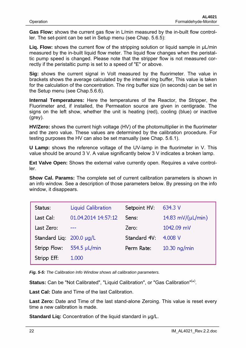
Show Cal. Params: The complete set of current calibration parameters is shown in an info window. See a description of those parameters below. By pressing on the info window, it disappears.
Fig. 5-5: The Calibration Info Window shows all calibration parameters.
Status: Can be "Not Calibrated", "Liquid Calibration", or "Gas Calibration"(*).
Last Cal: Date and Time of the last Calibration.
Last Zero: Date and Time of the last stand-alone Zeroing. This value is reset every time a new calibration is made.
Standard Liq: Concentration of the liquid standard in µg/L.
AL4021 Formaldehyde-Monitor Operation
IM_AL4021_Rev.2.2.doc 23
Stripp Flow: Flow of the stripping solution, determined during calibration (average).
Stripp Eff: Stripping efficiency. To be set in the Setup/Calibration menu.
Setpoint HV: High voltage of the photomultiplier in the fluorimeter. Set by the calibra-tion routine so that the output voltage is 4.0V when measuring the standard.
Zero: Zero level of the system: The output signal of the fluorimeter if no formalde-hyde is present in the sample.
Standard 4V: The real 4.0V output signal, when measuring the standard. Should be very close to 4.0V.
Perm rate: Permeation rate: output of the permeation unit. This value is determined in the Liquid Calibration routine, and used as gas standard in the Gas Calibration routine (*).
(*) Only displayed if a permeation unit is installed.
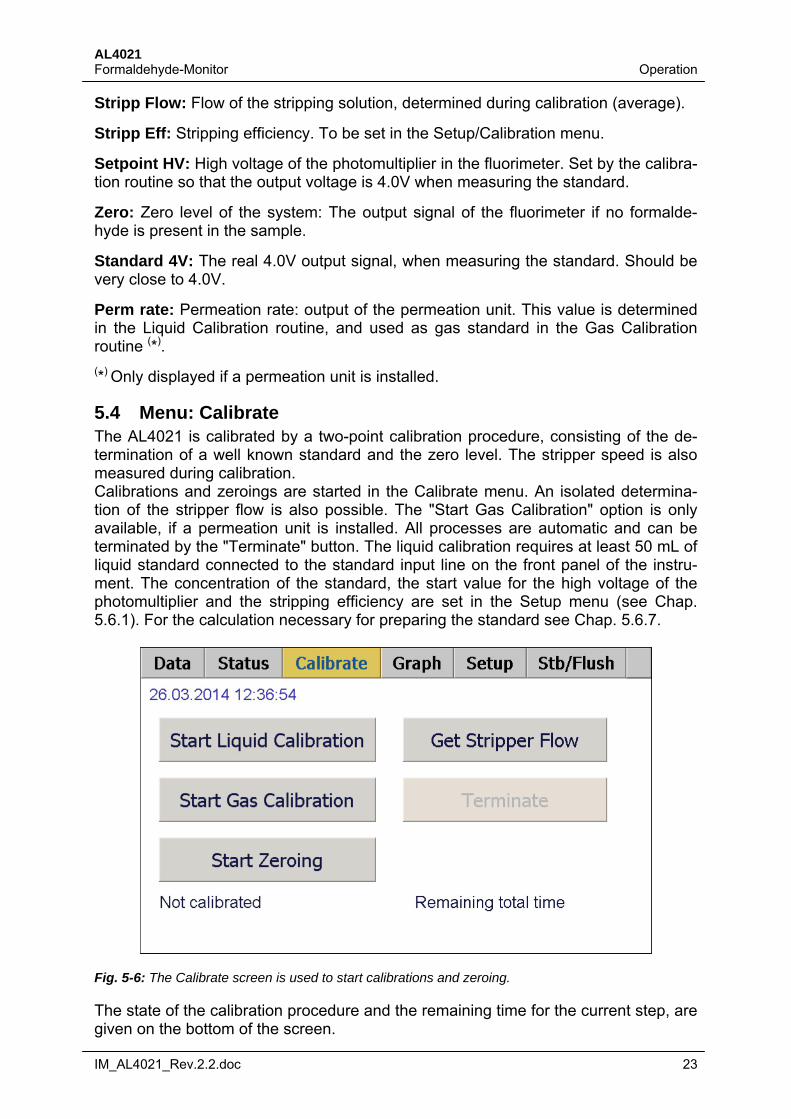
5.4 Menu: Calibrate The AL4021 is calibrated by a two-point calibration procedure, consisting of the de-termination of a well known standard and the zero level. The stripper speed is also measured during calibration. Calibrations and zeroings are started in the Calibrate menu. An isolated determina-tion of the stripper flow is also possible. The "Start Gas Calibration" option is only available, if a permeation unit is installed. All processes are automatic and can be terminated by the "Terminate" button. The liquid calibration requires at least 50 mL of liquid standard connected to the standard input line on the front panel of the instru-ment. The concentration of the standard, the start value for the high voltage of the photomultiplier and the stripping efficiency are set in the Setup menu (see Chap. 5.6.1). For the calculation necessary for preparing the standard see Chap. 5.6.7.
Fig. 5-6: The Calibrate screen is used to start calibrations and zeroing.
The state of the calibration procedure and the remaining time for the current step, are given on the bottom of the screen.
AL4021 Operation Formaldehyde-Monitor
24 IM_AL4021_Rev.2.2.doc
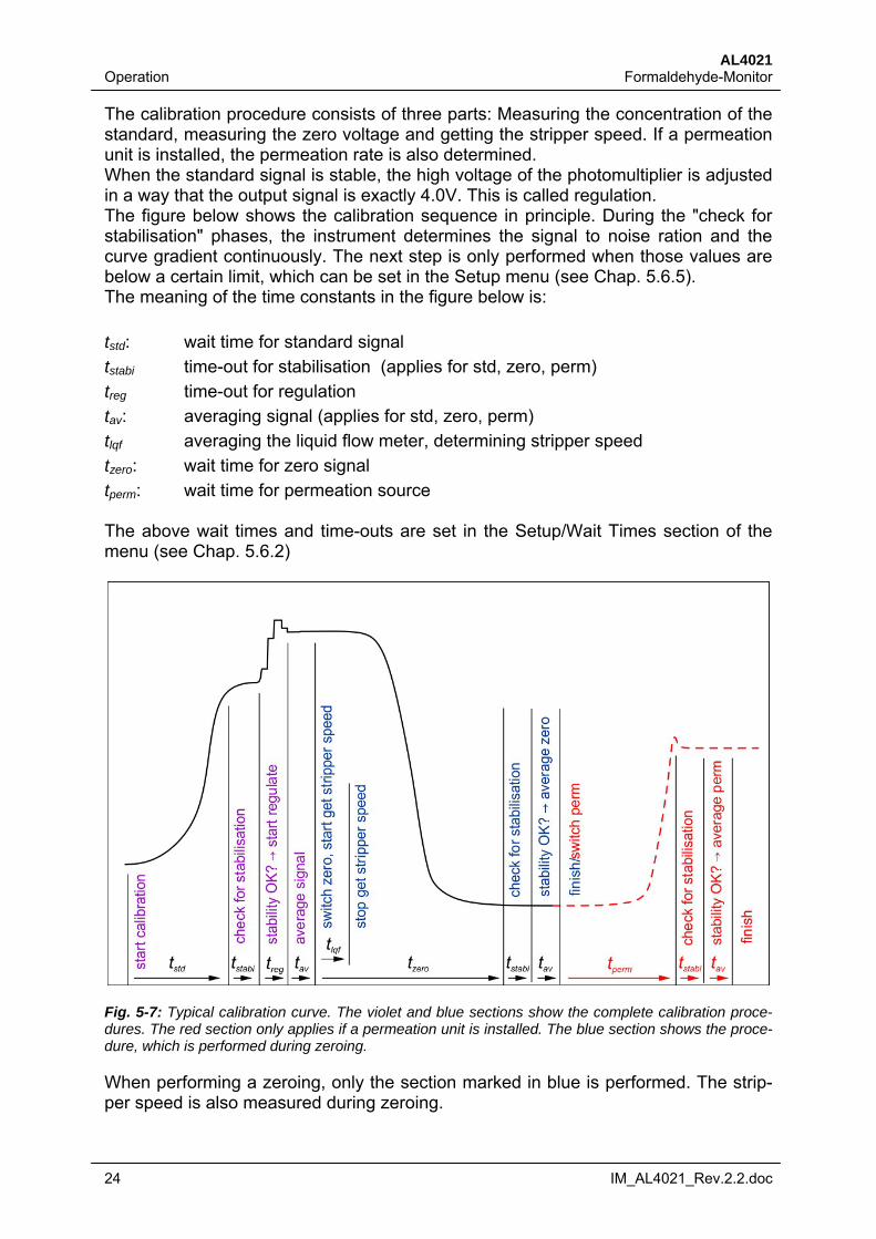
The calibration procedure consists of three parts: Measuring the concentration of the standard, measuring the zero voltage and getting the stripper speed. If a permeation unit is installed, the permeation rate is also determined. When the standard signal is stable, the high voltage of the photomultiplier is adjusted in a way that the output signal is exactly 4.0V. This is called regulation. The figure below shows the calibration sequence in principle. During the "check for stabilisation" phases, the instrument determines the signal to noise ration and the curve gradient continuously. The next step is only performed when those values are below a certain limit, which can be set in the Setup menu (see Chap. 5.6.5). The meaning of the time constants in the figure below is:
tstd: wait time for standard signal
tstabi time-out for stabilisation (applies for std, zero, perm)
treg time-out for regulation
tav: averaging signal (applies for std, zero, perm)
tlqf averaging the liquid flow meter, determining stripper speed
tzero: wait time for zero signal
tperm: wait time for permeation source The above wait times and time-outs are set in the Setup/Wait Times section of the menu (see Chap. 5.6.2)
Fig. 5-7: Typical calibration curve. The violet and blue sections show the complete calibration proce-dures. The red section only applies if a permeation unit is installed. The blue section shows the proce-dure, which is performed during zeroing.
When performing a zeroing, only the section marked in blue is performed. The strip-per speed is also measured during zeroing.
AL4021 Formaldehyde-Monitor Operation
IM_AL4021_Rev.2.2.doc 25
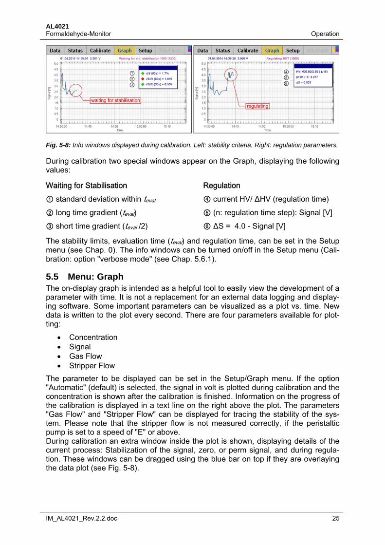
Fig. 5-8: Info windows displayed during calibration. Left: stability criteria. Right: regulation parameters.
During calibration two special windows appear on the Graph, displaying the following values:
Waiting for Stabilisation Regulation ① standard deviation within teval ④ current HV/ ΔHV (regulation time) ② long time gradient (teval) ⑤ (n: regulation time step): Signal [V] ③ short time gradient (teval /2) ⑥ ΔS = 4.0 - Signal [V]
The stability limits, evaluation time (teval) and regulation time, can be set in the Setup menu (see Chap. 0). The info windows can be turned on/off in the Setup menu (Cali-bration: option "verbose mode" (see Chap. 5.6.1).
5.5 Menu: Graph The on-display graph is intended as a helpful tool to easily view the development of a parameter with time. It is not a replacement for an external data logging and display-ing software. Some important parameters can be visualized as a plot vs. time. New data is written to the plot every second. There are four parameters available for plot-ting:
Concentration Signal Gas Flow Stripper Flow
The parameter to be displayed can be set in the Setup/Graph menu. If the option "Automatic" (default) is selected, the signal in volt is plotted during calibration and the concentration is shown after the calibration is finished. Information on the progress of the calibration is displayed in a text line on the right above the plot. The parameters "Gas Flow" and "Stripper Flow" can be displayed for tracing the stability of the sys-tem. Please note that the stripper flow is not measured correctly, if the peristaltic pump is set to a speed of "E" or above. During calibration an extra window inside the plot is shown, displaying details of the current process: Stabilization of the signal, zero, or perm signal, and during regula-tion. These windows can be dragged using the blue bar on top if they are overlaying the data plot (see Fig. 5-8).
AL4021 Operation Formaldehyde-Monitor
26 IM_AL4021_Rev.2.2.doc
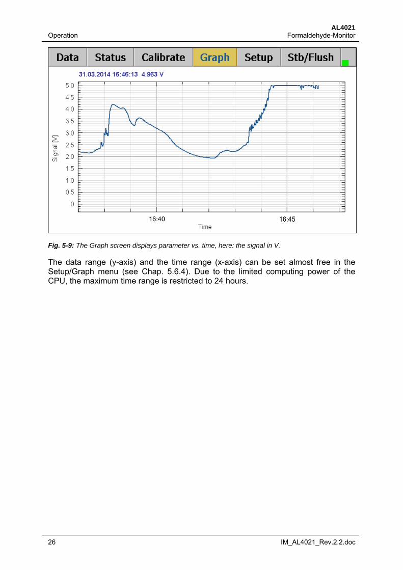
Fig. 5-9: The Graph screen displays parameter vs. time, here: the signal in V.
The data range (y-axis) and the time range (x-axis) can be set almost free in the Setup/Graph menu (see Chap. 5.6.4). Due to the limited computing power of the CPU, the maximum time range is restricted to 24 hours.
AL4021 Formaldehyde-Monitor Operation
IM_AL4021_Rev.2.2.doc 27
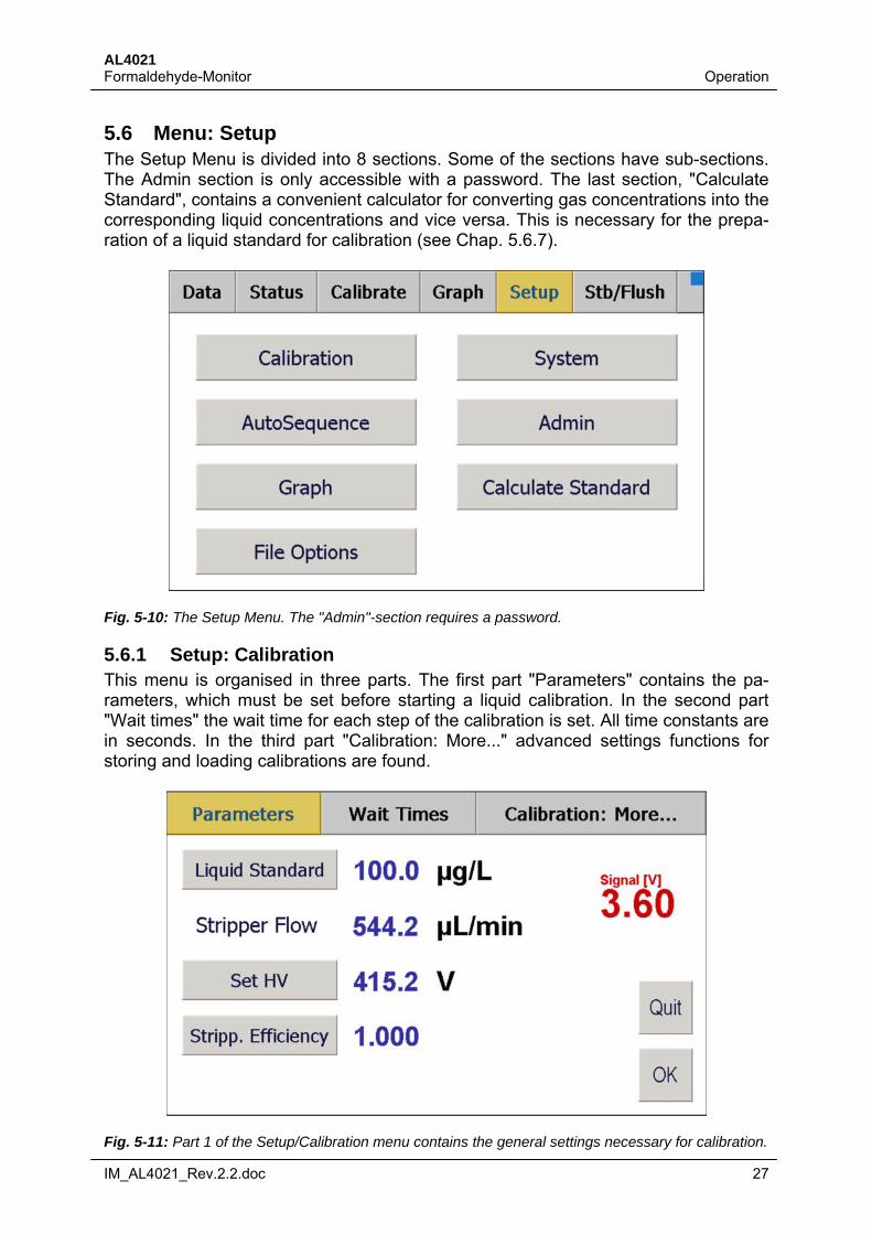
5.6 Menu: Setup The Setup Menu is divided into 8 sections. Some of the sections have sub-sections. The Admin section is only accessible with a password. The last section, "Calculate Standard", contains a convenient calculator for converting gas concentrations into the corresponding liquid concentrations and vice versa. This is necessary for the prepa-ration of a liquid standard for calibration (see Chap. 5.6.7).
Fig. 5-10: The Setup Menu. The "Admin"-section requires a password.
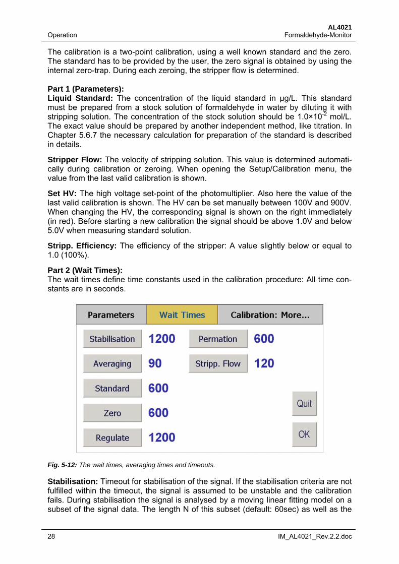
5.6.1 Setup: Calibration This menu is organised in three parts. The first part "Parameters" contains the pa-rameters, which must be set before starting a liquid calibration. In the second part "Wait times" the wait time for each step of the calibration is set. All time constants are in seconds. In the third part "Calibration: More..." advanced settings functions for storing and loading calibrations are found.
Fig. 5-11: Part 1 of the Setup/Calibration menu contains the general settings necessary for calibration.
AL4021 Operation Formaldehyde-Monitor
28 IM_AL4021_Rev.2.2.doc
The calibration is a two-point calibration, using a well known standard and the zero. The standard has to be provided by the user, the zero signal is obtained by using the internal zero-trap. During each zeroing, the stripper flow is determined. Part 1 (Parameters): Liquid Standard: The concentration of the liquid standard in µg/L. This standard must be prepared from a stock solution of formaldehyde in water by diluting it with stripping solution. The concentration of the stock solution should be 1.0×10⁻² mol/L. The exact value should be prepared by another independent method, like titration. In Chapter 5.6.7 the necessary calculation for preparation of the standard is described in details.
Stripper Flow: The velocity of stripping solution. This value is determined automati-cally during calibration or zeroing. When opening the Setup/Calibration menu, the value from the last valid calibration is shown.
Set HV: The high voltage set-point of the photomultiplier. Also here the value of the last valid calibration is shown. The HV can be set manually between 100V and 900V. When changing the HV, the corresponding signal is shown on the right immediately (in red). Before starting a new calibration the signal should be above 1.0V and below 5.0V when measuring standard solution.
Stripp. Efficiency: The efficiency of the stripper: A value slightly below or equal to 1.0 (100%).
Part 2 (Wait Times): The wait times define time constants used in the calibration procedure: All time con-stants are in seconds.
Fig. 5-12: The wait times, averaging times and timeouts.
Stabilisation: Timeout for stabilisation of the signal. If the stabilisation criteria are not fulfilled within the timeout, the signal is assumed to be unstable and the calibration fails. During stabilisation the signal is analysed by a moving linear fitting model on a subset of the signal data. The length N of this subset (default: 60sec) as well as the
AL4021 Formaldehyde-Monitor Operation
IM_AL4021_Rev.2.2.doc 29
stability limits, are set in the Setup/System menu (Chap. 5.6.5). The stabilisation cri-teria are:
Standard deviation of the signal (σS) over N seconds. Long time gradient (S/t) over N seconds. Short time gradient (S/t) over N/2 seconds.
The stabilisation timeout applies for the determination of the standard, the zero and the permeation signal (*). When all three stabilisation criteria are fulfilled the routine measures the signal, by averaging over the time set by the Averaging button.
Averaging: Time for averaging the signal after the signal has stabilised. The same time applies for standard, zero, and permeation signal (*).
Standard: Wait time after starting the calibration, before the signal is analysed for stabilisation.
Zero: Wait time after switching the zero-valve, before the signal is analysed for stabi-lisation.
Regulate: Timeout for the regulation routine. If the routine can't regulate the signal to 4 Volt within this time, the calibration fails.
Permeation: Wait time after switching to the permeation unit, before the signal is analysed for stabilisation (*).
Stripp. Flow: Averaging time for the determination of the stripper flow.
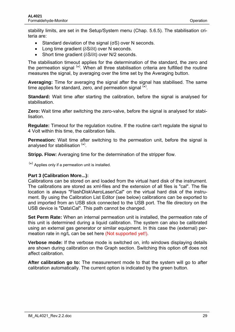
(*) Applies only if a permeation unit is installed. Part 3 (Calibration More...): Calibrations can be stored on and loaded from the virtual hard disk of the instrument. The calibrations are stored as xml-files and the extension of all files is "cal". The file location is always "FlashDisk\AeroLaser\Cal" on the virtual hard disk of the instru-ment. By using the Calibration List Editor (see below) calibrations can be exported to and imported from an USB stick connected to the USB port. The file directory on the USB device is "Data\Cal". This path cannot be changed.
Set Perm Rate: When an internal permeation unit is installed, the permeation rate of this unit is determined during a liquid calibration. The system can also be calibrated using an external gas generator or similar equipment. In this case the (external) per-meation rate in ng/L can be set here (Not supported yet!).
Verbose mode: If the verbose mode is switched on, info windows displaying details are shown during calibration on the Graph section. Switching this option off does not affect calibration.
After calibration go to: The measurement mode to that the system will go to after calibration automatically. The current option is indicated by the green button.
AL4021 Operation Formaldehyde-Monitor
30 IM_AL4021_Rev.2.2.doc
Fig. 5-13: Part 3 of the Setup/Calibration menu contains additional features.
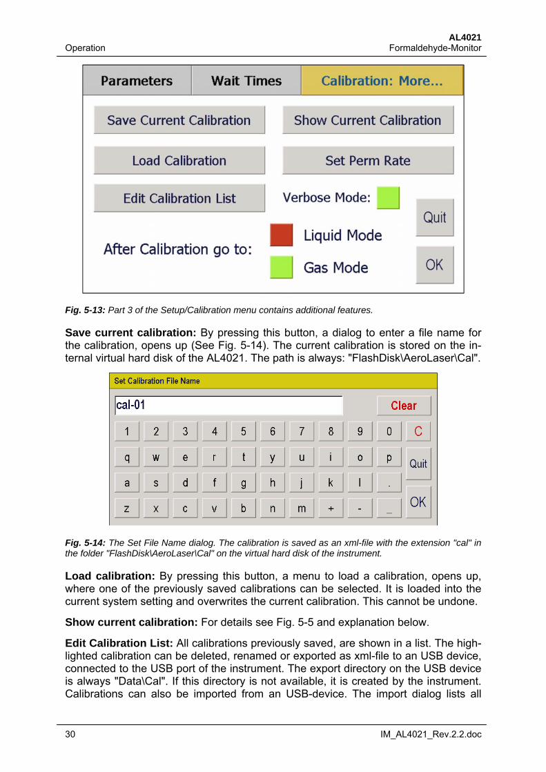
Save current calibration: By pressing this button, a dialog to enter a file name for the calibration, opens up (See Fig. 5-14). The current calibration is stored on the in-ternal virtual hard disk of the AL4021. The path is always: "FlashDisk\AeroLaser\Cal".
Fig. 5-14: The Set File Name dialog. The calibration is saved as an xml-file with the extension "cal" in the folder "FlashDisk\AeroLaser\Cal" on the virtual hard disk of the instrument.
Load calibration: By pressing this button, a menu to load a calibration, opens up, where one of the previously saved calibrations can be selected. It is loaded into the current system setting and overwrites the current calibration. This cannot be undone.
Show current calibration: For details see Fig. 5-5 and explanation below.
Edit Calibration List: All calibrations previously saved, are shown in a list. The high-lighted calibration can be deleted, renamed or exported as xml-file to an USB device, connected to the USB port of the instrument. The export directory on the USB device is always "Data\Cal". If this directory is not available, it is created by the instrument. Calibrations can also be imported from an USB-device. The import dialog lists all
AL4021 Formaldehyde-Monitor Operation
IM_AL4021_Rev.2.2.doc 31
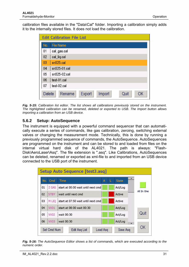
calibration files available in the "Data\Cal" folder. Importing a calibration simply adds it to the internally stored files. It does not load the calibration.
Fig. 5-15: Calibration list editor. The list shows all calibrations previously stored on the instrument. The highlighted calibration can be renamed, deleted or exported to USB. The Import button allows importing a calibration from an USB device.
5.6.2 Setup: AutoSequence The instrument is equipped with a powerful command sequencer that can automati-cally execute a series of commands, like gas calibration, zeroing, switching external valves or changing the measurement mode. Technically, this is done by running a previously programmed sequence of commands, the AutoSequence. AutoSequences are programmed on the instrument and can be stored to and loaded from files on the internal virtual hard disk of the AL4021. The path is always: "Flash-Disk\AeroLaser\Asq". The file extension is ".asq". Like Calibrations, AutoSequences can be deleted, renamed or exported as xml-file to and imported from an USB device connected to the USB port of the instrument.
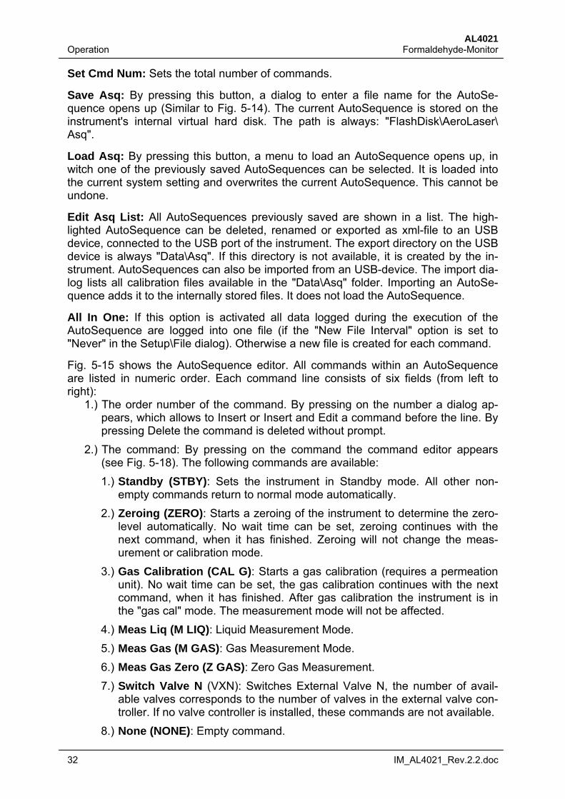
Fig. 5-16: The AutoSequence Editor shows a list of commands, which are executed according to the numeric order.
AL4021 Operation Formaldehyde-Monitor
32 IM_AL4021_Rev.2.2.doc
Set Cmd Num: Sets the total number of commands.
Save Asq: By pressing this button, a dialog to enter a file name for the AutoSe-quence opens up (Similar to Fig. 5-14). The current AutoSequence is stored on the instrument's internal virtual hard disk. The path is always: "FlashDisk\AeroLaser\ Asq".
Load Asq: By pressing this button, a menu to load an AutoSequence opens up, in witch one of the previously saved AutoSequences can be selected. It is loaded into the current system setting and overwrites the current AutoSequence. This cannot be undone.
Edit Asq List: All AutoSequences previously saved are shown in a list. The high-lighted AutoSequence can be deleted, renamed or exported as xml-file to an USB device, connected to the USB port of the instrument. The export directory on the USB device is always "Data\Asq". If this directory is not available, it is created by the in-strument. AutoSequences can also be imported from an USB-device. The import dia-log lists all calibration files available in the "Data\Asq" folder. Importing an AutoSe-quence adds it to the internally stored files. It does not load the AutoSequence.
All In One: If this option is activated all data logged during the execution of the AutoSequence are logged into one file (if the "New File Interval" option is set to "Never" in the Setup\File dialog). Otherwise a new file is created for each command.
Fig. 5-15 shows the AutoSequence editor. All commands within an AutoSequence are listed in numeric order. Each command line consists of six fields (from left to right):
1.) The order number of the command. By pressing on the number a dialog ap-pears, which allows to Insert or Insert and Edit a command before the line. By pressing Delete the command is deleted without prompt.
2.) The command: By pressing on the command the command editor appears (see Fig. 5-18). The following commands are available:
1.) Standby (STBY): Sets the instrument in Standby mode. All other non-empty commands return to normal mode automatically.
2.) Zeroing (ZERO): Starts a zeroing of the instrument to determine the zero-level automatically. No wait time can be set, zeroing continues with the next command, when it has finished. Zeroing will not change the meas-urement or calibration mode.
3.) Gas Calibration (CAL G): Starts a gas calibration (requires a permeation unit). No wait time can be set, the gas calibration continues with the next command, when it has finished. After gas calibration the instrument is in the "gas cal" mode. The measurement mode will not be affected.
4.) Meas Liq (M LIQ): Liquid Measurement Mode.
5.) Meas Gas (M GAS): Gas Measurement Mode.
6.) Meas Gas Zero (Z GAS): Zero Gas Measurement.
7.) Switch Valve N (VXN): Switches External Valve N, the number of avail-able valves corresponds to the number of valves in the external valve con-troller. If no valve controller is installed, these commands are not available.
8.) None (NONE): Empty command.
AL4021 Formaldehyde-Monitor Operation
IM_AL4021_Rev.2.2.doc 33
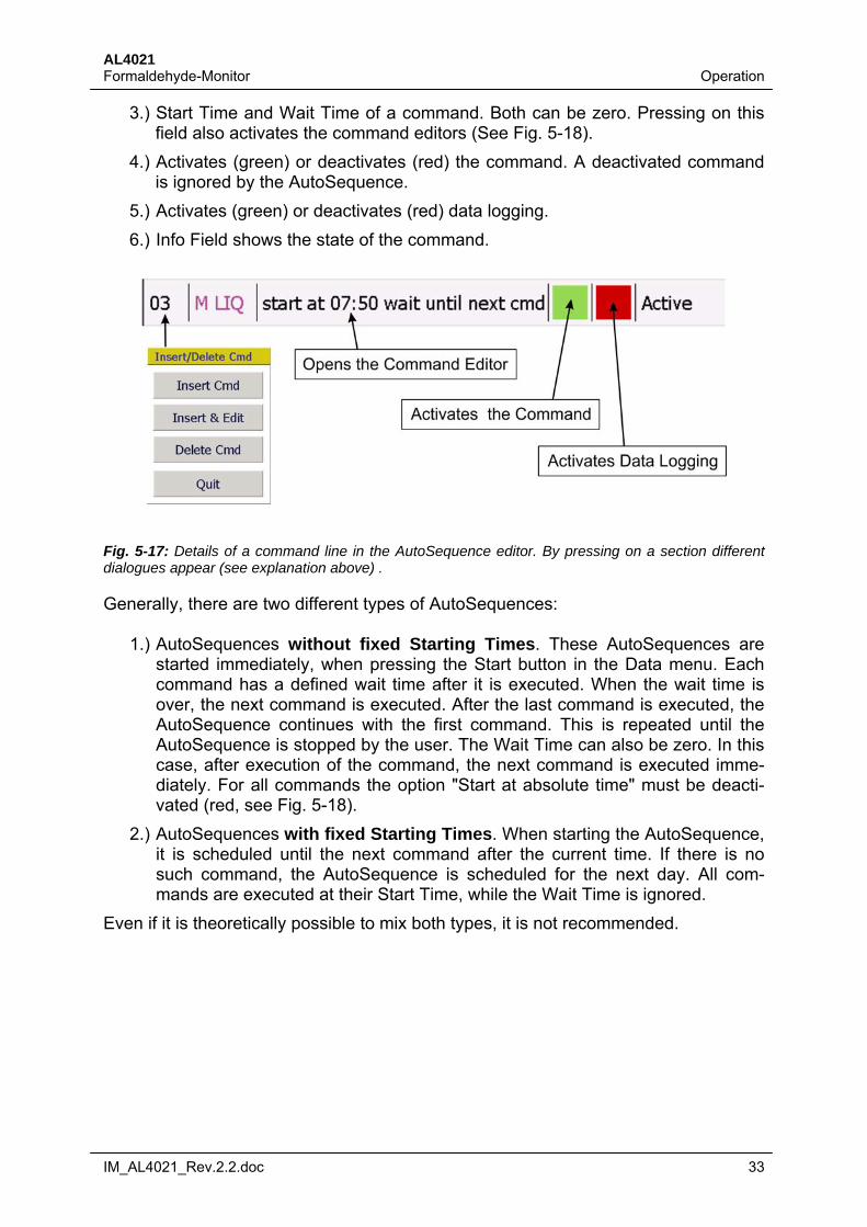
3.) Start Time and Wait Time of a command. Both can be zero. Pressing on this field also activates the command editors (See Fig. 5-18).
4.) Activates (green) or deactivates (red) the command. A deactivated command is ignored by the AutoSequence.
5.) Activates (green) or deactivates (red) data logging.
6.) Info Field shows the state of the command.
Fig. 5-17: Details of a command line in the AutoSequence editor. By pressing on a section different dialogues appear (see explanation above) .
Generally, there are two different types of AutoSequences:
1.) AutoSequences without fixed Starting Times. These AutoSequences are started immediately, when pressing the Start button in the Data menu. Each command has a defined wait time after it is executed. When the wait time is over, the next command is executed. After the last command is executed, the AutoSequence continues with the first command. This is repeated until the AutoSequence is stopped by the user. The Wait Time can also be zero. In this case, after execution of the command, the next command is executed imme-diately. For all commands the option "Start at absolute time" must be deacti-vated (red, see Fig. 5-18).
2.) AutoSequences with fixed Starting Times. When starting the AutoSequence, it is scheduled until the next command after the current time. If there is no such command, the AutoSequence is scheduled for the next day. All com-mands are executed at their Start Time, while the Wait Time is ignored.
Even if it is theoretically possible to mix both types, it is not recommended.
AL4021 Operation Formaldehyde-Monitor
34 IM_AL4021_Rev.2.2.doc
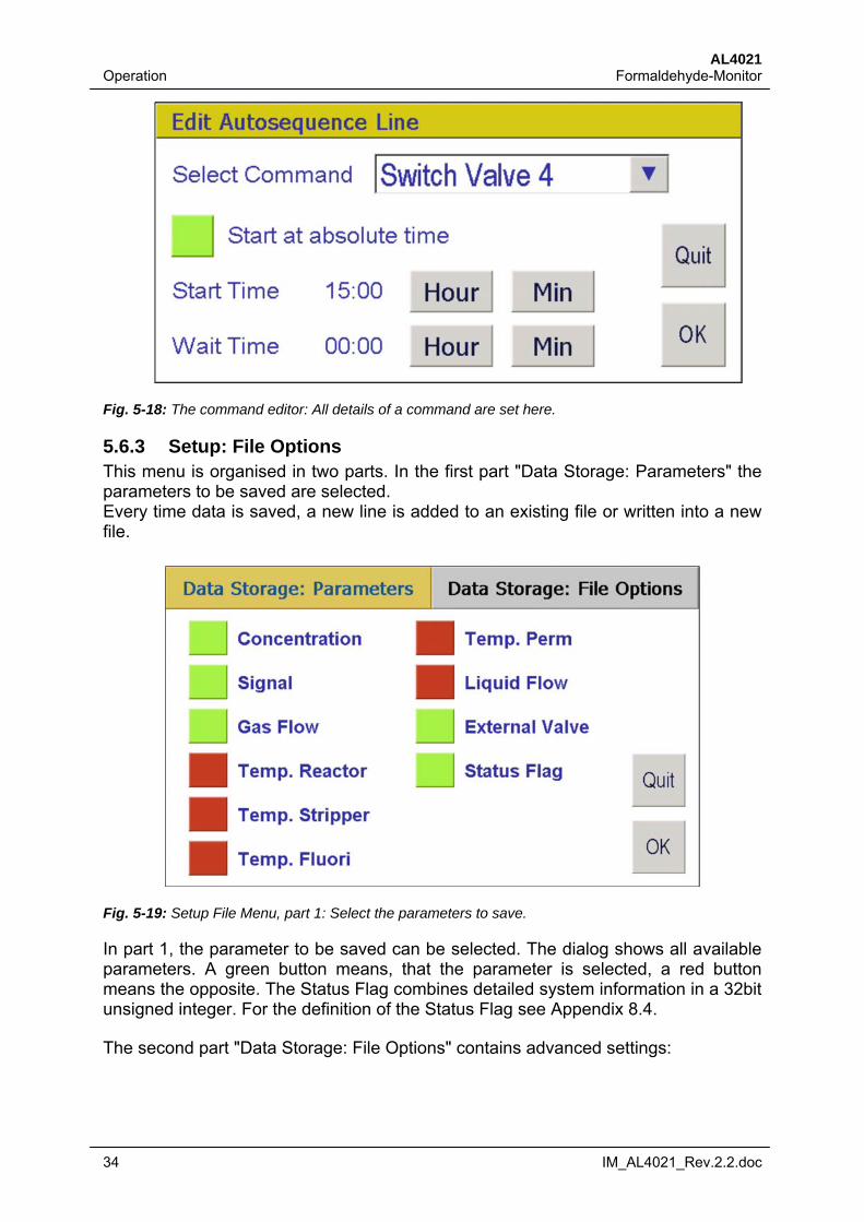
Fig. 5-18: The command editor: All details of a command are set here.
5.6.3 Setup: File Options This menu is organised in two parts. In the first part "Data Storage: Parameters" the parameters to be saved are selected. Every time data is saved, a new line is added to an existing file or written into a new file.
Fig. 5-19: Setup File Menu, part 1: Select the parameters to save.
In part 1, the parameter to be saved can be selected. The dialog shows all available parameters. A green button means, that the parameter is selected, a red button means the opposite. The Status Flag combines detailed system information in a 32bit unsigned integer. For the definition of the Status Flag see Appendix 8.4.
The second part "Data Storage: File Options" contains advanced settings:
AL4021 Formaldehyde-Monitor Operation
IM_AL4021_Rev.2.2.doc 35
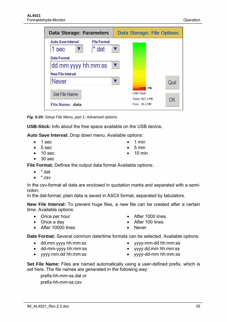
Fig. 5-20: Setup File Menu, part 1: Advanced options.
USB-Stick: Info about the free space available on the USB device.
Auto Save Interval: Drop down menu. Available options:
1 sec 5 sec 10 sec 30 sec
1 min 5 min 10 min
File Format: Defines the output data format Available options:.
*.dat *.csv
In the csv-format all data are enclosed in quotation marks and separated with a semi-colon. In the dat-format, plain data is saved in ASCII format, separated by tabulators.
New File Interval: To prevent huge files, a new file can be created after a certain time. Available options:
Once per hour Once a day After 10000 lines
After 1000 lines After 100 lines Never
Date Format: Several common date/time formats can be selected. Available options:
dd.mm.yyyy hh:mm:ss dd-mm-yyyy hh:mm:ss yyyy.mm.dd hh:mm:ss
yyyy-mm-dd hh:mm:ss yyyy.dd.mm hh:mm:ss yyyy-dd-mm hh:mm:ss
Set File Name: Files are named automatically using a user-defined prefix, which is set here. The file names are generated in the following way:
prefix-hh-mm-ss.dat or
prefix-hh-mm-ss.csv
AL4021 Operation Formaldehyde-Monitor
36 IM_AL4021_Rev.2.2.doc
On the USB medium inserted into the USB slot of the AL4021, a folder named "Data" is created. The data is stored into subfolders, which are named by the date of the day in the following way: "Data-yyyy-mm-dd".
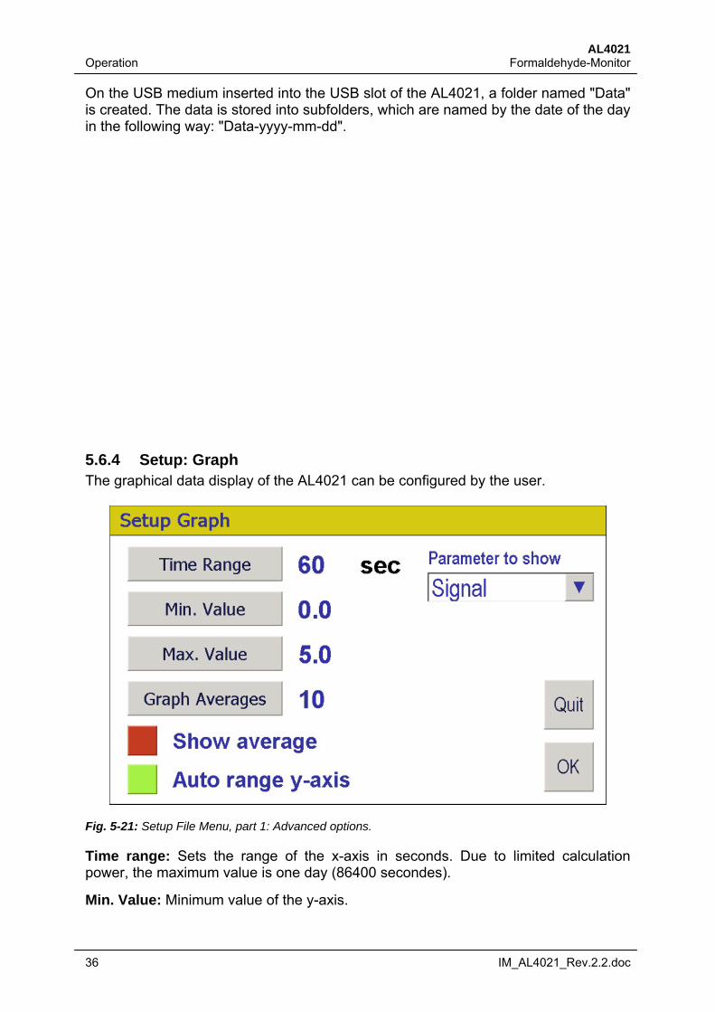
5.6.4 Setup: Graph The graphical data display of the AL4021 can be configured by the user.
Fig. 5-21: Setup File Menu, part 1: Advanced options.
Time range: Sets the range of the x-axis in seconds. Due to limited calculation power, the maximum value is one day (86400 secondes).
Min. Value: Minimum value of the y-axis.
AL4021 Formaldehyde-Monitor Operation
IM_AL4021_Rev.2.2.doc 37
Max. Value: Start Minimum value of the y-axis. In the example above the range of the y-axis is set from 0.0 – 5.0, which is the range of the analog signal.
Graph Averages: If the "Show Average" option is selected, the graphic display can show a moving average of the data. Here the number of data points (seconds) to av-erage is set.
Show Averages: Turn the display of an moving average on/off.
Auto range y-axis: The graphic display can resize the y-axis if the data go beyond the limits set above. Here this option is turned on/off.
Parameters to show: Selects the parameter to display. Available options:
Automatic (recommended) Concentration Signal Gas Flow Liquid Flow
If the option "Automatic" is selected, the display shows the signal during calibrations and the concentration otherwise.
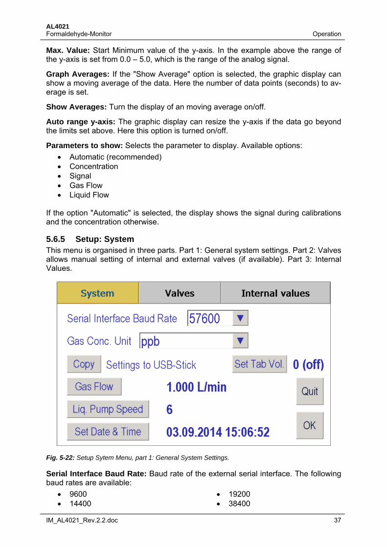
5.6.5 Setup: System This menu is organised in three parts. Part 1: General system settings. Part 2: Valves allows manual setting of internal and external valves (if available). Part 3: Internal Values.
Fig. 5-22: Setup Sytem Menu, part 1: General System Settings.
Serial Interface Baud Rate: Baud rate of the external serial interface. The following baud rates are available:
9600 14400
19200 38400
AL4021 Operation Formaldehyde-Monitor
38 IM_AL4021_Rev.2.2.doc
57600 115200
For the other parameters of the interface see Chapter 8.2. Please note, that the pa-rameters of the serial interface must be equal to the setting on the remote PC.
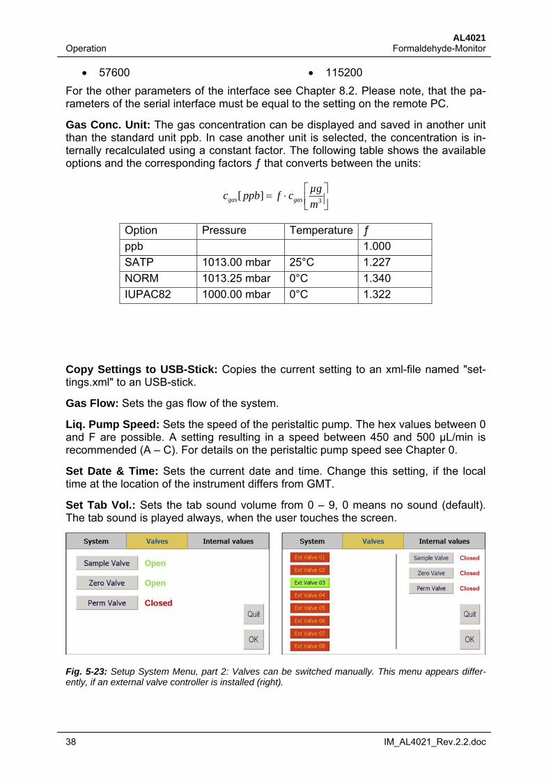
Gas Conc. Unit: The gas concentration can be displayed and saved in another unit than the standard unit ppb. In case another unit is selected, the concentration is in-ternally recalculated using a constant factor. The following table shows the available options and the corresponding factors ƒ that converts between the units:
3][
m
µgcfppbc gasgas
Option Pressure Temperature ƒ
ppb 1.000
SATP 1013.00 mbar 25°C 1.227
NORM 1013.25 mbar 0°C 1.340
IUPAC82 1000.00 mbar 0°C 1.322
Copy Settings to USB-Stick: Copies the current setting to an xml-file named "set-tings.xml" to an USB-stick.
Gas Flow: Sets the gas flow of the system.
Liq. Pump Speed: Sets the speed of the peristaltic pump. The hex values between 0 and F are possible. A setting resulting in a speed between 450 and 500 µL/min is recommended (A – C). For details on the peristaltic pump speed see Chapter 0.
Set Date & Time: Sets the current date and time. Change this setting, if the local time at the location of the instrument differs from GMT.
Set Tab Vol.: Sets the tab sound volume from 0 – 9, 0 means no sound (default). The tab sound is played always, when the user touches the screen.
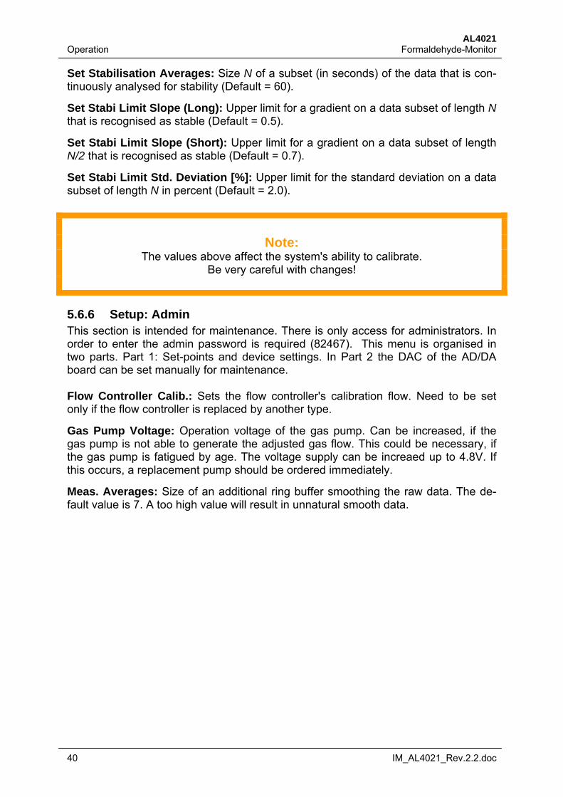
Fig. 5-23: Setup System Menu, part 2: Valves can be switched manually. This menu appears differ-ently, if an external valve controller is installed (right).
AL4021 Formaldehyde-Monitor Operation
IM_AL4021_Rev.2.2.doc 39
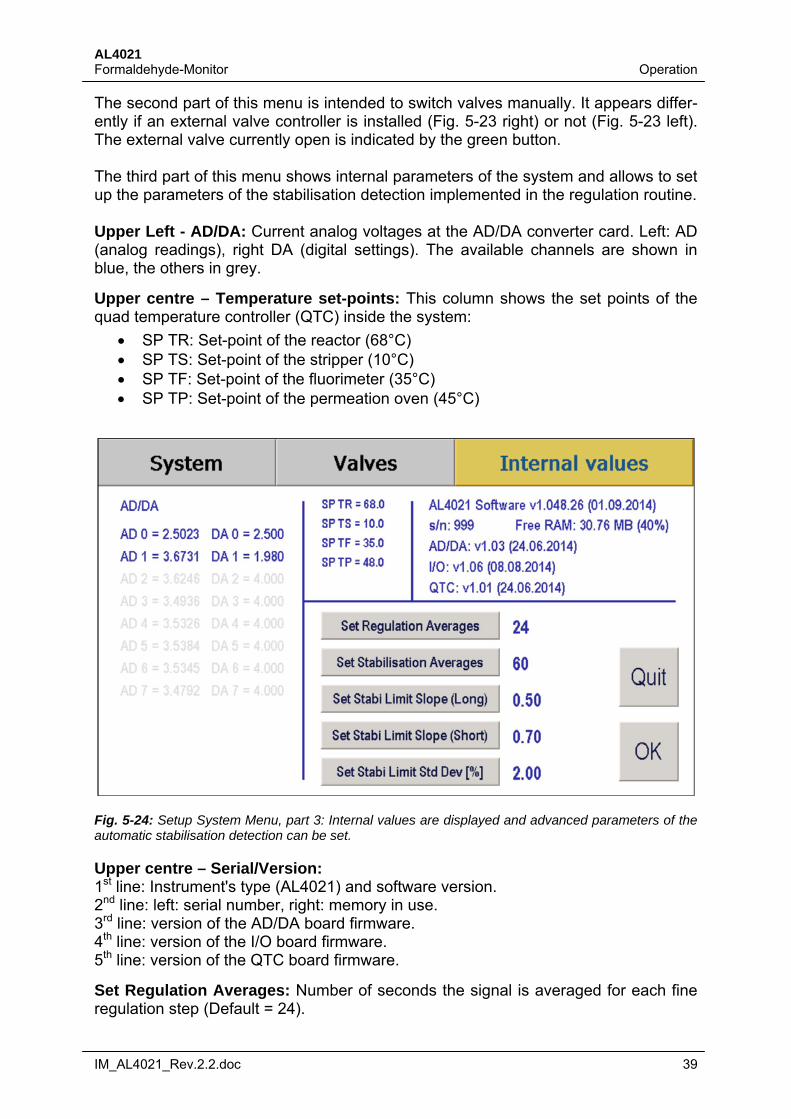
The second part of this menu is intended to switch valves manually. It appears differ-ently if an external valve controller is installed (Fig. 5-23 right) or not (Fig. 5-23 left). The external valve currently open is indicated by the green button. The third part of this menu shows internal parameters of the system and allows to set up the parameters of the stabilisation detection implemented in the regulation routine. Upper Left - AD/DA: Current analog voltages at the AD/DA converter card. Left: AD (analog readings), right DA (digital settings). The available channels are shown in blue, the others in grey.
Upper centre – Temperature set-points: This column shows the set points of the quad temperature controller (QTC) inside the system:
SP TR: Set-point of the reactor (68°C) SP TS: Set-point of the stripper (10°C) SP TF: Set-point of the fluorimeter (35°C) SP TP: Set-point of the permeation oven (45°C)
Fig. 5-24: Setup System Menu, part 3: Internal values are displayed and advanced parameters of the automatic stabilisation detection can be set.
Upper centre – Serial/Version: 1st line: Instrument's type (AL4021) and software version. 2nd line: left: serial number, right: memory in use. 3rd line: version of the AD/DA board firmware. 4th line: version of the I/O board firmware. 5th line: version of the QTC board firmware.
Set Regulation Averages: Number of seconds the signal is averaged for each fine regulation step (Default = 24).
AL4021 Operation Formaldehyde-Monitor
40 IM_AL4021_Rev.2.2.doc
Set Stabilisation Averages: Size N of a subset (in seconds) of the data that is con-tinuously analysed for stability (Default = 60).
Set Stabi Limit Slope (Long): Upper limit for a gradient on a data subset of length N that is recognised as stable (Default = 0.5).
Set Stabi Limit Slope (Short): Upper limit for a gradient on a data subset of length N/2 that is recognised as stable (Default = 0.7).
Set Stabi Limit Std. Deviation [%]: Upper limit for the standard deviation on a data subset of length N in percent (Default = 2.0).
Note:
The values above affect the system's ability to calibrate. Be very careful with changes!
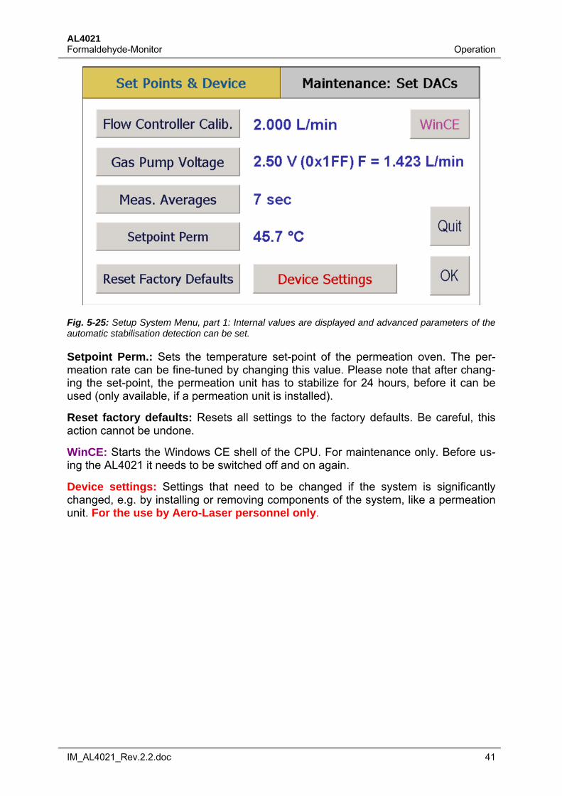
5.6.6 Setup: Admin This section is intended for maintenance. There is only access for administrators. In order to enter the admin password is required (82467). This menu is organised in two parts. Part 1: Set-points and device settings. In Part 2 the DAC of the AD/DA board can be set manually for maintenance. Flow Controller Calib.: Sets the flow controller's calibration flow. Need to be set only if the flow controller is replaced by another type.
Gas Pump Voltage: Operation voltage of the gas pump. Can be increased, if the gas pump is not able to generate the adjusted gas flow. This could be necessary, if the gas pump is fatigued by age. The voltage supply can be increaed up to 4.8V. If this occurs, a replacement pump should be ordered immediately.
Meas. Averages: Size of an additional ring buffer smoothing the raw data. The de-fault value is 7. A too high value will result in unnatural smooth data.
AL4021 Formaldehyde-Monitor Operation
IM_AL4021_Rev.2.2.doc 41
Fig. 5-25: Setup System Menu, part 1: Internal values are displayed and advanced parameters of the automatic stabilisation detection can be set.
Setpoint Perm.: Sets the temperature set-point of the permeation oven. The per-meation rate can be fine-tuned by changing this value. Please note that after chang-ing the set-point, the permeation unit has to stabilize for 24 hours, before it can be used (only available, if a permeation unit is installed).
Reset factory defaults: Resets all settings to the factory defaults. Be careful, this action cannot be undone.
WinCE: Starts the Windows CE shell of the CPU. For maintenance only. Before us-ing the AL4021 it needs to be switched off and on again.
Device settings: Settings that need to be changed if the system is significantly changed, e.g. by installing or removing components of the system, like a permeation unit. For the use by Aero-Laser personnel only.
AL4021 Operation Formaldehyde-Monitor
42 IM_AL4021_Rev.2.2.doc
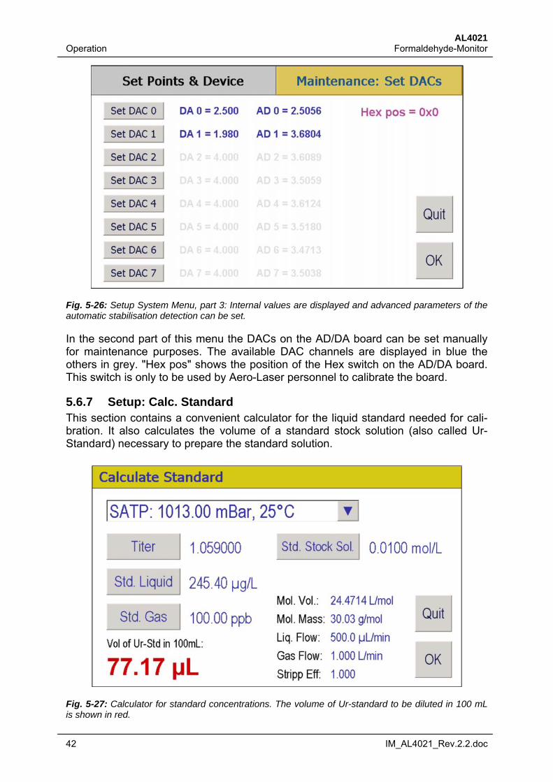
Fig. 5-26: Setup System Menu, part 3: Internal values are displayed and advanced parameters of the automatic stabilisation detection can be set.
In the second part of this menu the DACs on the AD/DA board can be set manually for maintenance purposes. The available DAC channels are displayed in blue the others in grey. "Hex pos" shows the position of the Hex switch on the AD/DA board. This switch is only to be used by Aero-Laser personnel to calibrate the board.
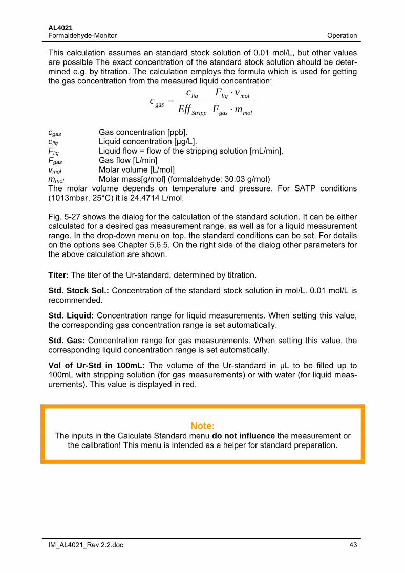
5.6.7 Setup: Calc. Standard This section contains a convenient calculator for the liquid standard needed for cali-bration. It also calculates the volume of a standard stock solution (also called Ur-Standard) necessary to prepare the standard solution.
Fig. 5-27: Calculator for standard concentrations. The volume of Ur-standard to be diluted in 100 mL is shown in red.
AL4021 Formaldehyde-Monitor Operation
IM_AL4021_Rev.2.2.doc 43
This calculation assumes an standard stock solution of 0.01 mol/L, but other values are possible The exact concentration of the standard stock solution should be deter-mined e.g. by titration. The calculation employs the formula which is used for getting the gas concentration from the measured liquid concentration:
molgas
molliq
Stripp
liq
gas mF
vF
Eff
cc
cgas Gas concentration [ppb]. cliq Liquid concentration [µg/L]. Fliq Liquid flow = flow of the stripping solution [mL/min]. Fgas Gas flow [L/min] vmol Molar volume [L/mol] mmol Molar mass[g/mol] (formaldehyde: 30.03 g/mol) The molar volume depends on temperature and pressure. For SATP conditions (1013mbar, 25°C) it is 24.4714 L/mol. Fig. 5-27 shows the dialog for the calculation of the standard solution. It can be either calculated for a desired gas measurement range, as well as for a liquid measurement range. In the drop-down menu on top, the standard conditions can be set. For details on the options see Chapter 5.6.5. On the right side of the dialog other parameters for the above calculation are shown. Titer: The titer of the Ur-standard, determined by titration.
Std. Stock Sol.: Concentration of the standard stock solution in mol/L. 0.01 mol/L is recommended.
Std. Liquid: Concentration range for liquid measurements. When setting this value, the corresponding gas concentration range is set automatically.
Std. Gas: Concentration range for gas measurements. When setting this value, the corresponding liquid concentration range is set automatically.
Vol of Ur-Std in 100mL: The volume of the Ur-standard in µL to be filled up to 100mL with stripping solution (for gas measurements) or with water (for liquid meas-urements). This value is displayed in red.
Note:
The inputs in the Calculate Standard menu do not influence the measurement or the calibration! This menu is intended as a helper for standard preparation.
AL4021 Operation Formaldehyde-Monitor
44 IM_AL4021_Rev.2.2.doc
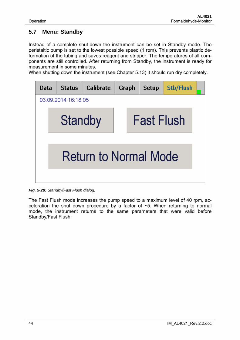
5.7 Menu: Standby Instead of a complete shut-down the instrument can be set in Standby mode. The peristaltic pump is set to the lowest possible speed (1 rpm). This prevents plastic de-formation of the tubing and saves reagent and stripper. The temperatures of all com-ponents are still controlled. After returning from Standby, the instrument is ready for measurement in some minutes. When shutting down the instrument (see Chapter 5.13) it should run dry completely.
Fig. 5-28: Standby/Fast Flush dialog.
The Fast Flush mode increases the pump speed to a maximum level of 40 rpm, ac-celeration the shut down procedure by a factor of ~5. When returning to normal mode, the instrument returns to the same parameters that were valid before Standby/Fast Flush.
AL4021 Formaldehyde-Monitor Operation
IM_AL4021_Rev.2.2.doc 45
5.8 SqeezeDat SqeezeDat is a data base software based on the widely used SQL standard. It was designed to record the data of up to 8 individual Aero-Laser instruments via the RS232 interface. The data can be exported from the SQL data base to ASCII or XML format for further calculations or analysis. SqeezeDat works with all Aero-Laser in-struments. Furthermore it can record data from other non Aero-Laser devices, if they are equipped with a RS232 interface and use a compatible command structure. While recording, SqeezeDat can display graphically up to 8 parameters in separate windows. For an enhanced clarity, more than one parameter can be displayed in a single window
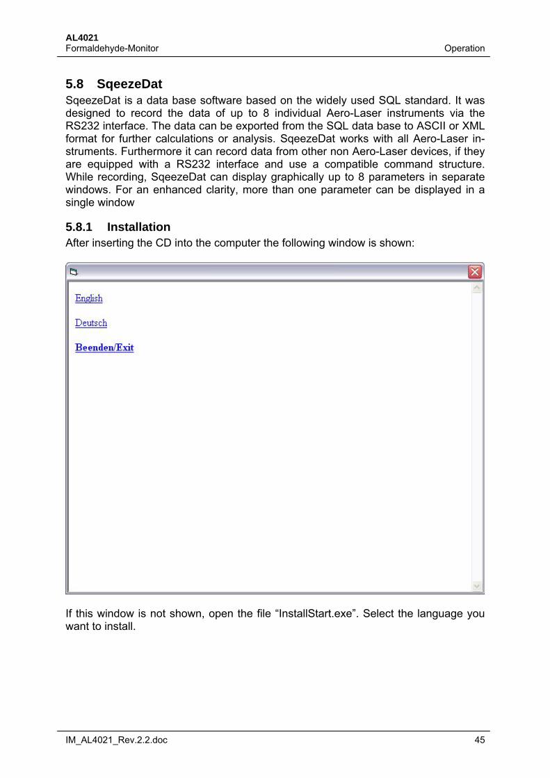
5.8.1 Installation After inserting the CD into the computer the following window is shown:
If this window is not shown, open the file “InstallStart.exe”. Select the language you want to install.
AL4021 Operation Formaldehyde-Monitor
46 IM_AL4021_Rev.2.2.doc
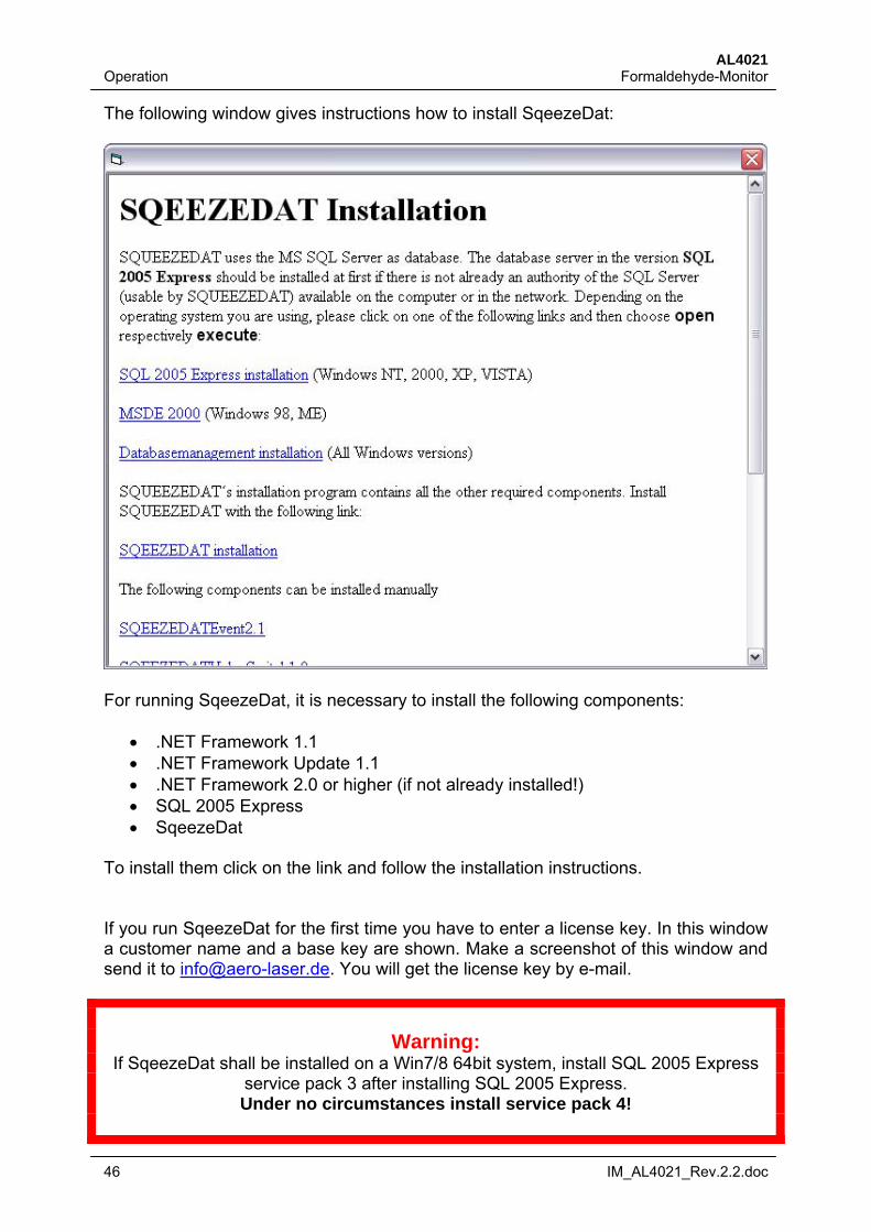
The following window gives instructions how to install SqeezeDat:
For running SqeezeDat, it is necessary to install the following components:
.NET Framework 1.1 .NET Framework Update 1.1 .NET Framework 2.0 or higher (if not already installed!) SQL 2005 Express SqeezeDat
To install them click on the link and follow the installation instructions. If you run SqeezeDat for the first time you have to enter a license key. In this window a customer name and a base key are shown. Make a screenshot of this window and send it to [email protected]. You will get the license key by e-mail.
Warning:
If SqeezeDat shall be installed on a Win7/8 64bit system, install SQL 2005 Express service pack 3 after installing SQL 2005 Express. Under no circumstances install service pack 4!
AL4021 Formaldehyde-Monitor Operation
IM_AL4021_Rev.2.2.doc 47
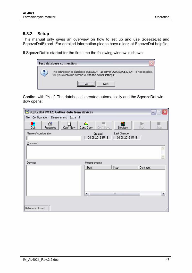
5.8.2 Setup This manual only gives an overview on how to set up and use SqeezeDat and SqeezeDatExport. For detailed information please have a look at SqeezeDat helpfile. If SqeezeDat is started for the first time the following window is shown:
Confirm with “Yes”. The database is created automatically and the SqeezeDat win-dow opens:
AL4021 Operation Formaldehyde-Monitor
48 IM_AL4021_Rev.2.2.doc
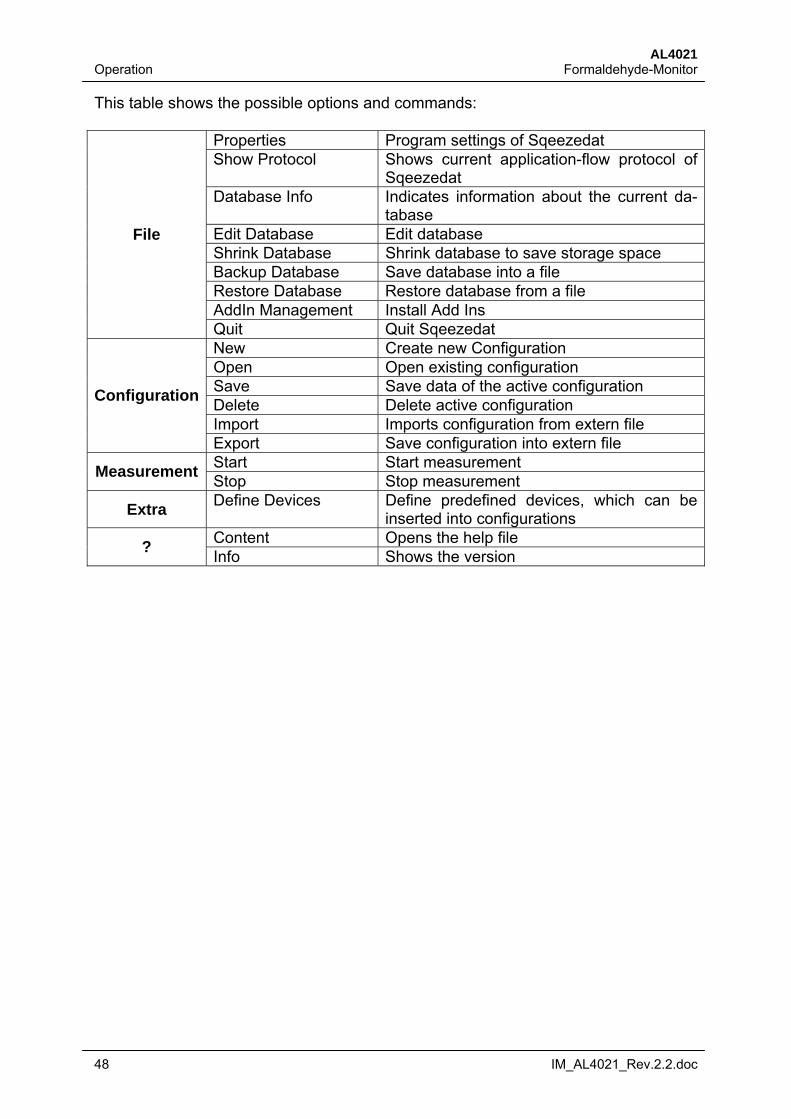
This table shows the possible options and commands:
Properties Program settings of Sqeezedat Show Protocol Shows current application-flow protocol of
Sqeezedat Database Info Indicates information about the current da-
tabase Edit Database Edit database Shrink Database Shrink database to save storage space Backup Database Save database into a file Restore Database Restore database from a file AddIn Management Install Add Ins
File
Quit Quit Sqeezedat New Create new Configuration Open Open existing configuration Save Save data of the active configuration Delete Delete active configuration Import Imports configuration from extern file
Configuration
Export Save configuration into extern file Start Start measurement
Measurement Stop Stop measurement
Extra Define Devices Define predefined devices, which can be
inserted into configurations Content Opens the help file
? Info Shows the version
AL4021 Formaldehyde-Monitor Operation
IM_AL4021_Rev.2.2.doc 49
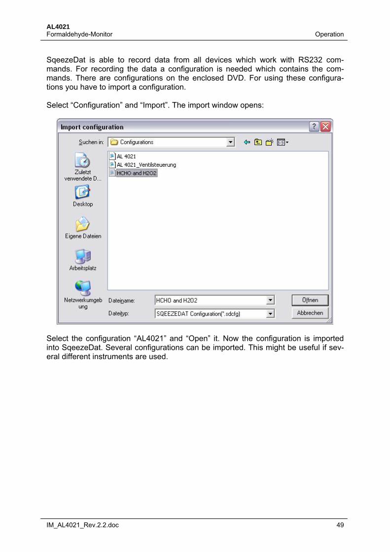
SqeezeDat is able to record data from all devices which work with RS232 com-mands. For recording the data a configuration is needed which contains the com-mands. There are configurations on the enclosed DVD. For using these configura-tions you have to import a configuration. Select “Configuration” and “Import”. The import window opens:
Select the configuration “AL4021” and “Open” it. Now the configuration is imported into SqeezeDat. Several configurations can be imported. This might be useful if sev-eral different instruments are used.
AL4021 Operation Formaldehyde-Monitor
50 IM_AL4021_Rev.2.2.doc
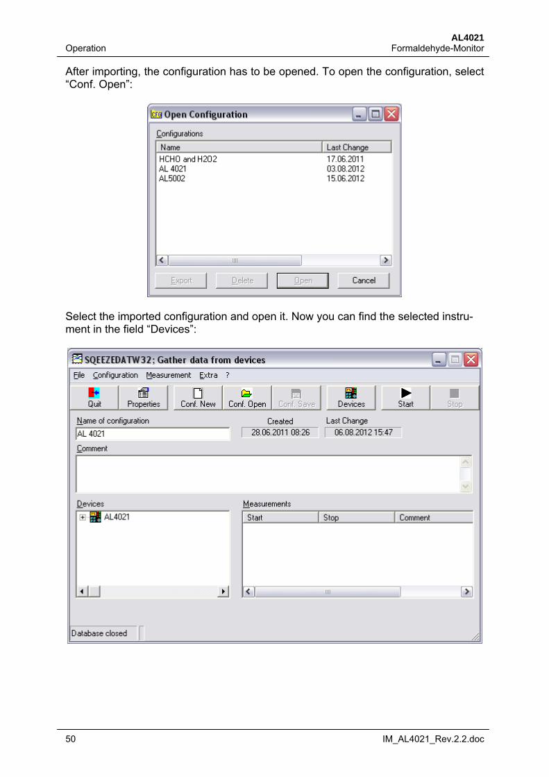
After importing, the configuration has to be opened. To open the configuration, select “Conf. Open”:
Select the imported configuration and open it. Now you can find the selected instru-ment in the field “Devices”:
AL4021 Formaldehyde-Monitor Operation
IM_AL4021_Rev.2.2.doc 51
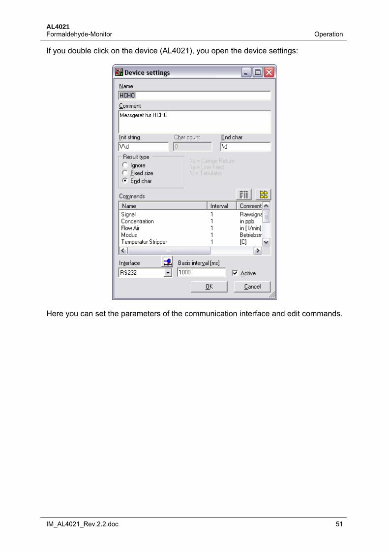
If you double click on the device (AL4021), you open the device settings:
Here you can set the parameters of the communication interface and edit commands.
AL4021 Operation Formaldehyde-Monitor
52 IM_AL4021_Rev.2.2.doc
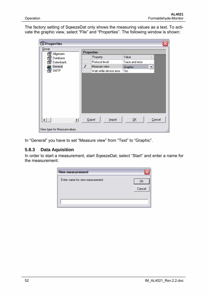
The factory setting of SqeezeDat only shows the measuring values as a text. To acti-vate the graphic view, select “File” and “Properties”. The following window is shown:
In “General” you have to set “Measure view” from “Text” to “Graphic”.
5.8.3 Data Aquisition In order to start a measurement, start SqeezeDat, select “Start” and enter a name for the measurement:
AL4021 Formaldehyde-Monitor Operation
IM_AL4021_Rev.2.2.doc 53
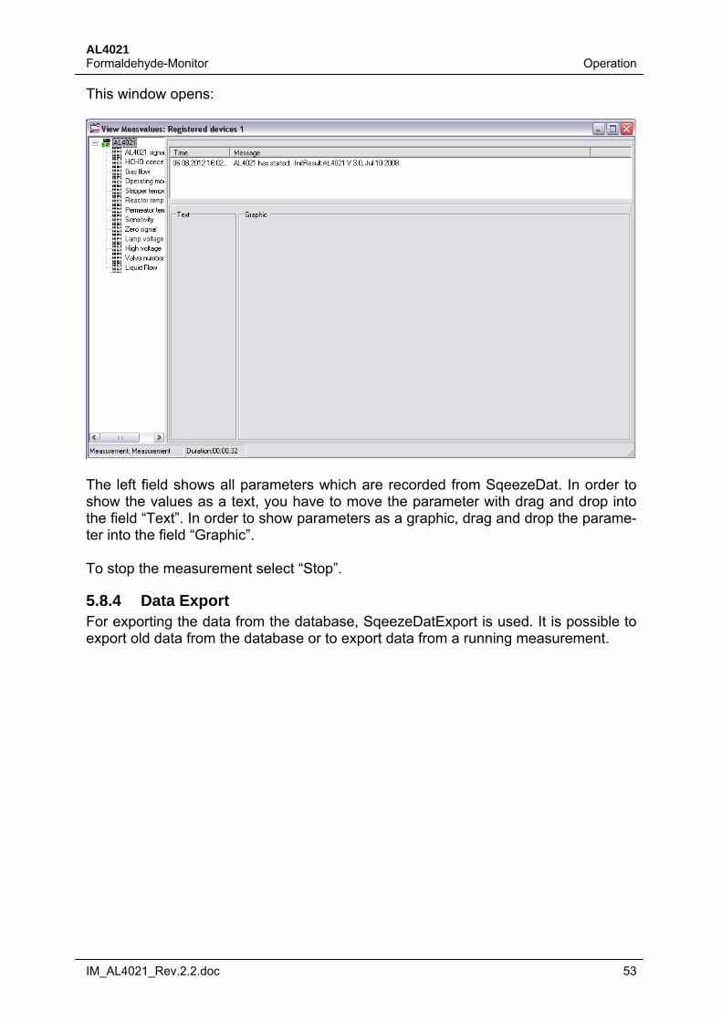
This window opens:
The left field shows all parameters which are recorded from SqeezeDat. In order to show the values as a text, you have to move the parameter with drag and drop into the field “Text”. In order to show parameters as a graphic, drag and drop the parame-ter into the field “Graphic”. To stop the measurement select “Stop”.
5.8.4 Data Export For exporting the data from the database, SqeezeDatExport is used. It is possible to export old data from the database or to export data from a running measurement.
AL4021 Operation Formaldehyde-Monitor
54 IM_AL4021_Rev.2.2.doc
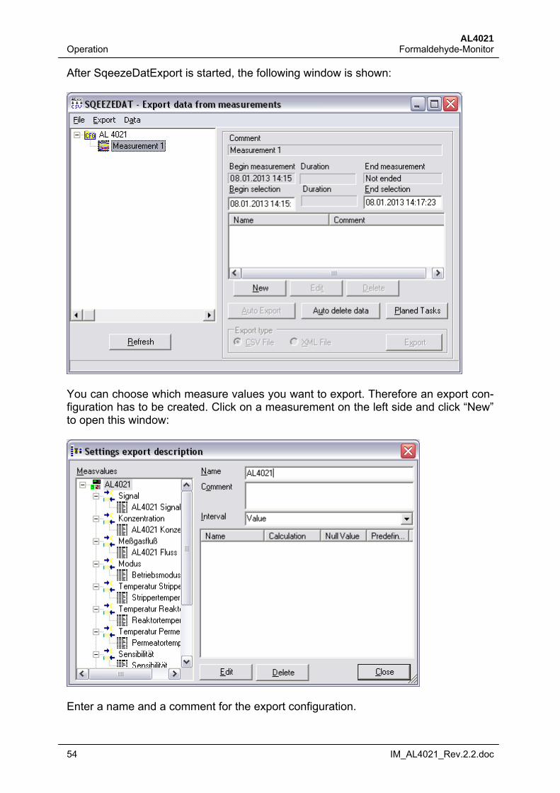
After SqeezeDatExport is started, the following window is shown:
You can choose which measure values you want to export. Therefore an export con-figuration has to be created. Click on a measurement on the left side and click “New” to open this window:
Enter a name and a comment for the export configuration.
AL4021 Formaldehyde-Monitor Operation
IM_AL4021_Rev.2.2.doc 55
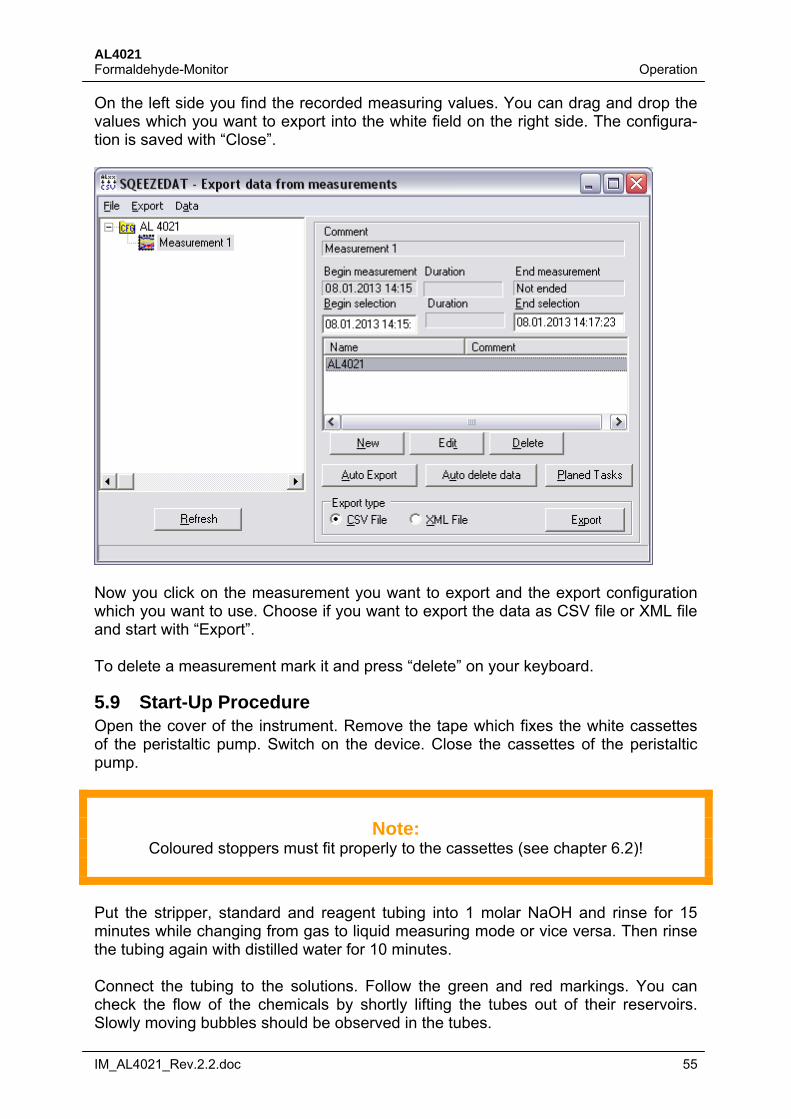
On the left side you find the recorded measuring values. You can drag and drop the values which you want to export into the white field on the right side. The configura-tion is saved with “Close”.
Now you click on the measurement you want to export and the export configuration which you want to use. Choose if you want to export the data as CSV file or XML file and start with “Export”. To delete a measurement mark it and press “delete” on your keyboard.
5.9 Start-Up Procedure Open the cover of the instrument. Remove the tape which fixes the white cassettes of the peristaltic pump. Switch on the device. Close the cassettes of the peristaltic pump.
Note:
Coloured stoppers must fit properly to the cassettes (see chapter 6.2)!
Put the stripper, standard and reagent tubing into 1 molar NaOH and rinse for 15 minutes while changing from gas to liquid measuring mode or vice versa. Then rinse the tubing again with distilled water for 10 minutes. Connect the tubing to the solutions. Follow the green and red markings. You can check the flow of the chemicals by shortly lifting the tubes out of their reservoirs. Slowly moving bubbles should be observed in the tubes.
AL4021 Operation Formaldehyde-Monitor
56 IM_AL4021_Rev.2.2.doc
5.10 Calibration/Zeroing The AL4021 uses a two point calibration. A gas or liquid standard with known con-centration is used to adjust the photomultiplier to the measuring range. The zero sig-nal is determined with the internal zero trap. Zeroings and gas calibrations can be scheduled automatically using AutoSequences (see Chapter 5.6.2).
5.10.1 Measuring Stripper Speed (if no Liquid Flow Meter is installed) For measuring gaseous concentrations, formaldehyde is solved into the stripping so-lution. The concentration of formaldehyde in the stripping solution is measured in the liquid phase. For calculating the correct concentration in gas phase, the speed of the stripping solution has to be measured. If the optional liquid flow meter is mounted, the stripper speed is measured automati-cally.
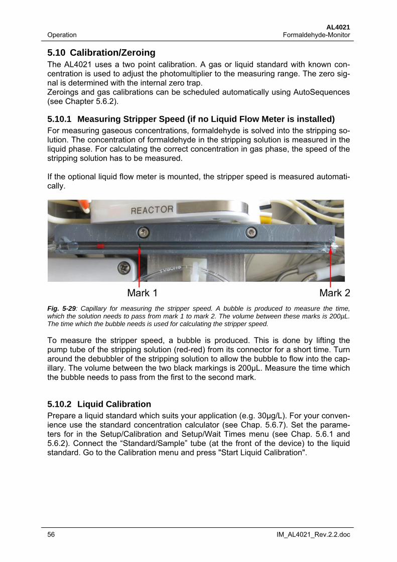
Fig. 5-29: Capillary for measuring the stripper speed. A bubble is produced to measure the time, which the solution needs to pass from mark 1 to mark 2. The volume between these marks is 200µL. The time which the bubble needs is used for calculating the stripper speed.
To measure the stripper speed, a bubble is produced. This is done by lifting the pump tube of the stripping solution (red-red) from its connector for a short time. Turn around the debubbler of the stripping solution to allow the bubble to flow into the cap-illary. The volume between the two black markings is 200µL. Measure the time which the bubble needs to pass from the first to the second mark.
5.10.2 Liquid Calibration Prepare a liquid standard which suits your application (e.g. 30µg/L). For your conven-ience use the standard concentration calculator (see Chap. 5.6.7). Set the parame-ters for in the Setup/Calibration and Setup/Wait Times menu (see Chap. 5.6.1 and 5.6.2). Connect the “Standard/Sample” tube (at the front of the device) to the liquid standard. Go to the Calibration menu and press "Start Liquid Calibration".
AL4021 Formaldehyde-Monitor Operation
IM_AL4021_Rev.2.2.doc 57
0 10 20 30 40 50 600
1
2
3
4
5S
igna
l[V
]
Time [min]
Typical AL4021 calibration curve Regulation
Standard
Zero signal
Permeation source
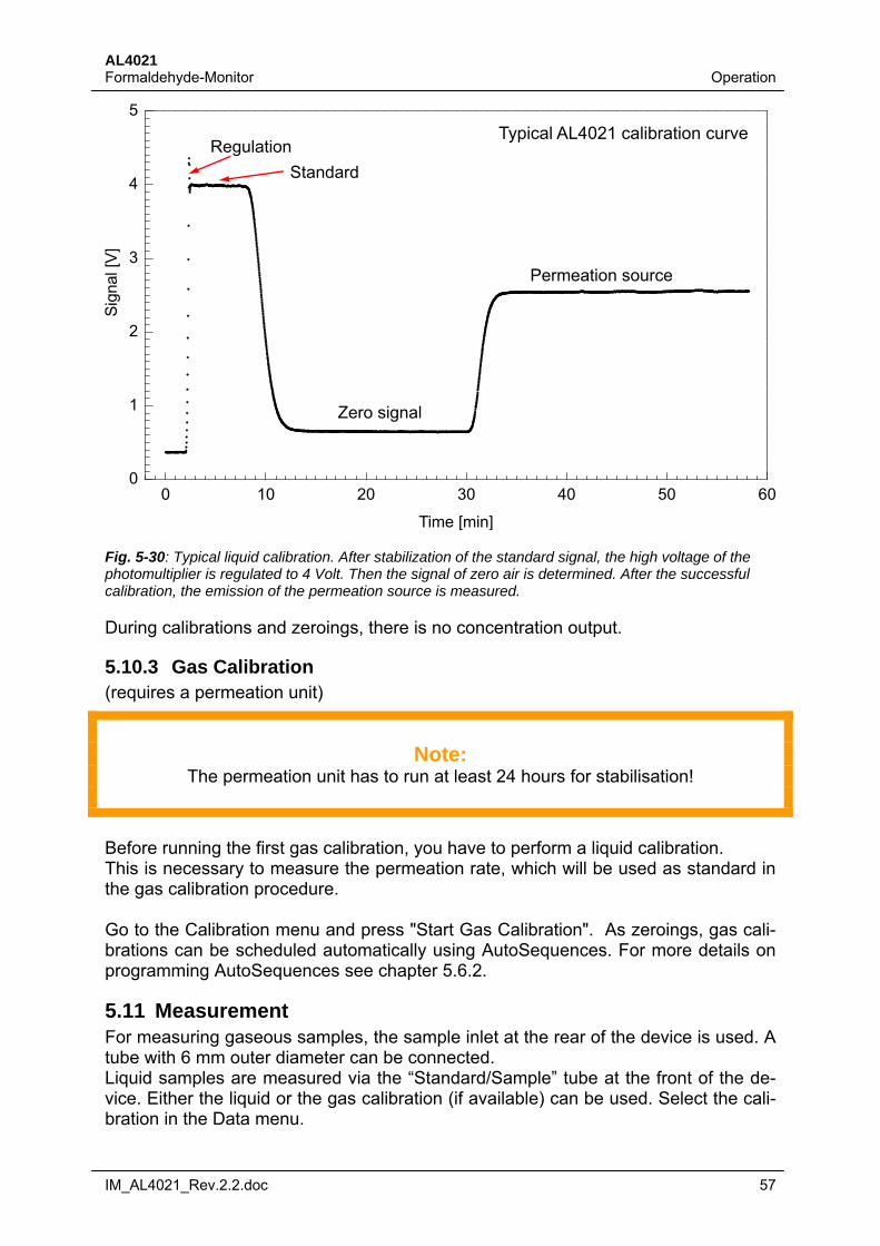
Fig. 5-30: Typical liquid calibration. After stabilization of the standard signal, the high voltage of the photomultiplier is regulated to 4 Volt. Then the signal of zero air is determined. After the successful calibration, the emission of the permeation source is measured.
During calibrations and zeroings, there is no concentration output.
5.10.3 Gas Calibration (requires a permeation unit)
Note:
The permeation unit has to run at least 24 hours for stabilisation!
Before running the first gas calibration, you have to perform a liquid calibration. This is necessary to measure the permeation rate, which will be used as standard in the gas calibration procedure. Go to the Calibration menu and press "Start Gas Calibration". As zeroings, gas cali-brations can be scheduled automatically using AutoSequences. For more details on programming AutoSequences see chapter 5.6.2.
5.11 Measurement For measuring gaseous samples, the sample inlet at the rear of the device is used. A tube with 6 mm outer diameter can be connected. Liquid samples are measured via the “Standard/Sample” tube at the front of the de-vice. Either the liquid or the gas calibration (if available) can be used. Select the cali-bration in the Data menu.
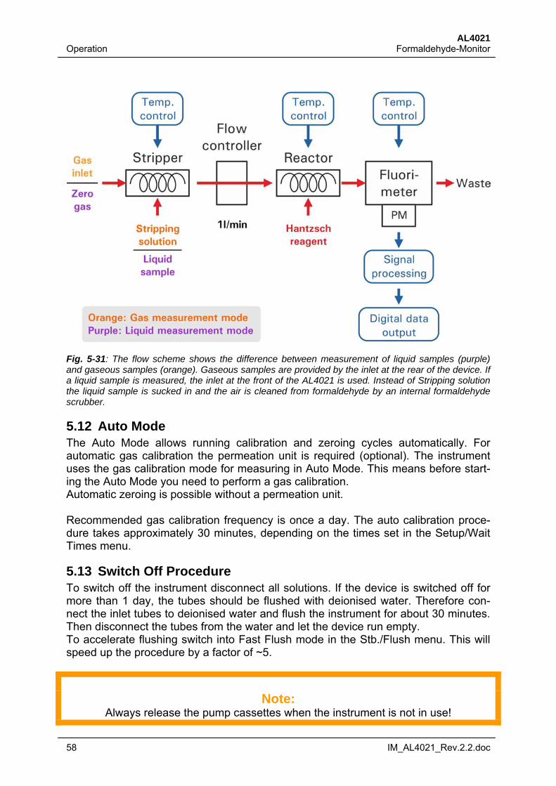
AL4021 Operation Formaldehyde-Monitor
58 IM_AL4021_Rev.2.2.doc
Fig. 5-31: The flow scheme shows the difference between measurement of liquid samples (purple) and gaseous samples (orange). Gaseous samples are provided by the inlet at the rear of the device. If a liquid sample is measured, the inlet at the front of the AL4021 is used. Instead of Stripping solution the liquid sample is sucked in and the air is cleaned from formaldehyde by an internal formaldehyde scrubber.
5.12 Auto Mode The Auto Mode allows running calibration and zeroing cycles automatically. For automatic gas calibration the permeation unit is required (optional). The instrument uses the gas calibration mode for measuring in Auto Mode. This means before start-ing the Auto Mode you need to perform a gas calibration. Automatic zeroing is possible without a permeation unit. Recommended gas calibration frequency is once a day. The auto calibration proce-dure takes approximately 30 minutes, depending on the times set in the Setup/Wait Times menu.
5.13 Switch Off Procedure To switch off the instrument disconnect all solutions. If the device is switched off for more than 1 day, the tubes should be flushed with deionised water. Therefore con-nect the inlet tubes to deionised water and flush the instrument for about 30 minutes. Then disconnect the tubes from the water and let the device run empty. To accelerate flushing switch into Fast Flush mode in the Stb./Flush menu. This will speed up the procedure by a factor of ~5.
Note:
Always release the pump cassettes when the instrument is not in use!
AL4021 Formaldehyde-Monitor Maintenance
IM_AL4021_Rev.2.2.doc 59
6 Maintenance
6.1 Cleaning To clean the instrument, put the stripper, standard and reagent tubing into 1 molar NaOH and rinse for 10 minutes while changing from gas to liquid mode or vice versa. Then rinse the tubing again with deionised water for 30 minutes.
Warning:
Do not use acids like HCl for cleaning!
6.2 Tubes and Replacement The pump tubes have a lifetime of approximately 2 weeks if the device is operated under 24/7 conditions. After that time the flow will become unstable and will cause signal noise which has a negative effect to the accuracy. If the AL4021 is used under other conditions, the lifetime changes and can be calculated. For replacement of the tubes, disconnect the solutions and let the device run empty. Then open the cover, release the cassettes, remove and replace the tubes according to the scheme and color code below. Pump tubes and color code REACTOR: Yellow / Blue CUVETTE: White / White REAGENT DEBUB.: Orange / Yellow REAGENT: Orange / Orange STRIPPING DEBUB.: Orange / Yellow STRIPPING SOL.: Red / Red
Note:
Make sure that the peristaltic tube stoppers are properly installed in the peristaltic pump and that the inlet tubes are not kinked or bent!
Pump tubes have a longer life time when the outside is greased with silicon grease.
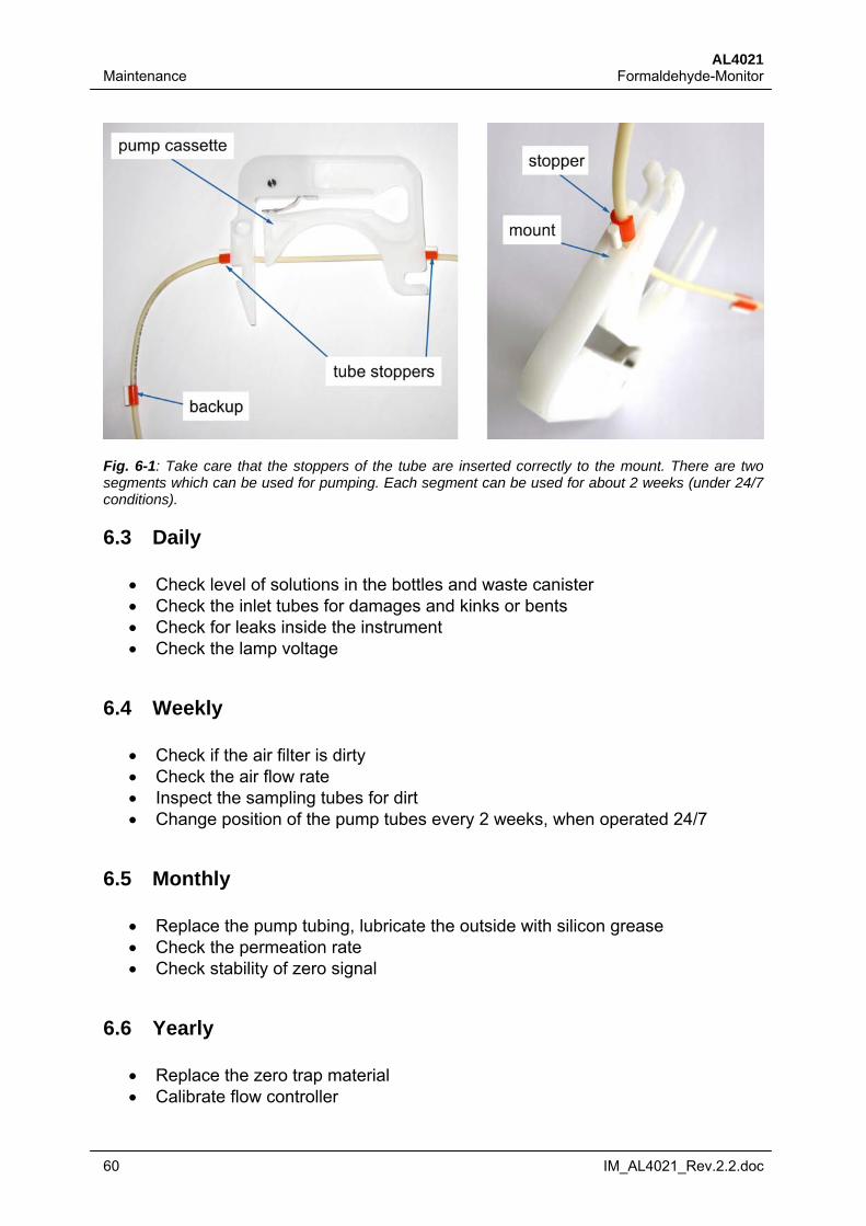
AL4021 Maintenance Formaldehyde-Monitor
60 IM_AL4021_Rev.2.2.doc
Fig. 6-1: Take care that the stoppers of the tube are inserted correctly to the mount. There are two segments which can be used for pumping. Each segment can be used for about 2 weeks (under 24/7 conditions).
6.3 Daily
Check level of solutions in the bottles and waste canister Check the inlet tubes for damages and kinks or bents Check for leaks inside the instrument Check the lamp voltage
6.4 Weekly
Check if the air filter is dirty Check the air flow rate Inspect the sampling tubes for dirt Change position of the pump tubes every 2 weeks, when operated 24/7
6.5 Monthly
Replace the pump tubing, lubricate the outside with silicon grease Check the permeation rate Check stability of zero signal
6.6 Yearly
Replace the zero trap material Calibrate flow controller
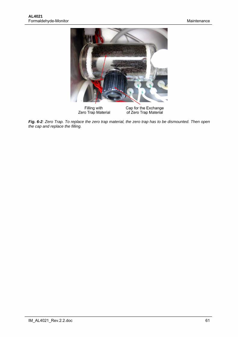
AL4021 Formaldehyde-Monitor Maintenance
IM_AL4021_Rev.2.2.doc 61
Fig. 6-2: Zero Trap. To replace the zero trap material, the zero trap has to be dismounted. Then open the cap and replace the filling.
AL4021 Troubleshooting Formaldehyde-Monitor
62 IM_AL4021_Rev.2.2.doc
7 Troubleshooting
7.1 System is Not Booting
Check AC power supply Check if the device is switched on Check the fuse at the switch Check if all LED’s of the internal DC power supply glow Check if the LED’s of the AD/DA, I/O and QTC boards flash
7.2 No Lamp Signal
Check the cables of the UV-LED board Check DC power supply
7.3 Peristaltic Pump
7.3.1 Pump does not rotate
Check if there is a liquid trap error Check 24 Volt power supply Check if the cable of the pump is connected
7.4 Bubbles in Cell
7.4.1 If debubbler operates normally
Check the cell connectors for leaks
7.4.2 If bubbles are too large for debubbler
Check the inlet tubes for blocks and damages Check if the tubes are connected to the solutions Check if you are in gas or liquid measurement mode
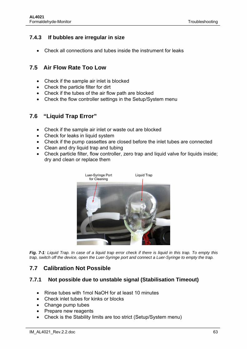
AL4021 Formaldehyde-Monitor Troubleshooting
IM_AL4021_Rev.2.2.doc 63
7.4.3 If bubbles are irregular in size
Check all connections and tubes inside the instrument for leaks
7.5 Air Flow Rate Too Low
Check if the sample air inlet is blocked Check the particle filter for dirt Check if the tubes of the air flow path are blocked Check the flow controller settings in the Setup/System menu
7.6 “Liquid Trap Error”
Check if the sample air inlet or waste out are blocked Check for leaks in liquid system Check if the pump cassettes are closed before the inlet tubes are connected Clean and dry liquid trap and tubing Check particle filter, flow controller, zero trap and liquid valve for liquids inside;
dry and clean or replace them
Fig. 7-1: Liquid Trap. In case of a liquid trap error check if there is liquid in this trap. To empty this trap, switch off the device, open the Luer-Syringe port and connect a Luer-Syringe to empty the trap.
7.7 Calibration Not Possible
7.7.1 Not possible due to unstable signal (Stabilisation Timeout)
Rinse tubes with 1mol NaOH for at least 10 minutes Check inlet tubes for kinks or blocks Change pump tubes Prepare new reagents Check is the Stability limits are too strict (Setup/System menu)
AL4021 Troubleshooting Formaldehyde-Monitor
64 IM_AL4021_Rev.2.2.doc
7.7.2 Unable to regulate HV (Regulation Timeout)
Check if concentration of liquid standard is too high Check if the regulation timeout (Setup/Wait Times menu) is too short Check if the standard signal is stable
7.8 No Connection to PC
Check if the instrument and the PC are connected with a null modem cable (Pin 2 and Pin 3 crossed)
Check COM port and parameters of the COM port are the same in the instru-ment and the remote PC
Check if another program is using the COM port If a USB to RS232 adapter is used, check if the driver is installed
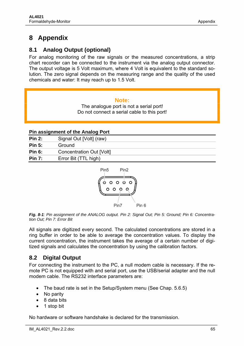
AL4021 Formaldehyde-Monitor Appendix
IM_AL4021_Rev.2.2.doc 65
8 Appendix
8.1 Analog Output (optional) For analog monitoring of the raw signals or the measured concentrations, a strip chart recorder can be connected to the instrument via the analog output connector. The output voltage is 5 Volt maximum, where 4 Volt is equivalent to the standard so-lution. The zero signal depends on the measuring range and the quality of the used chemicals and water: It may reach up to 1.5 Volt.
Note:
The analogue port is not a serial port! Do not connect a serial cable to this port!
Pin assignment of the Analog Port Pin 2: Signal Out [Volt] (raw) Pin 5: Ground Pin 6: Concentration Out [Volt] Pin 7: Error Bit (TTL high)
Fig. 8-1: Pin assignment of the ANALOG output. Pin 2: Signal Out; Pin 5: Ground; Pin 6: Concentra-tion Out; Pin 7: Error Bit
All signals are digitized every second. The calculated concentrations are stored in a ring buffer in order to be able to average the concentration values. To display the current concentration, the instrument takes the average of a certain number of digi-tized signals and calculates the concentration by using the calibration factors.
8.2 Digital Output For connecting the instrument to the PC, a null modem cable is necessary. If the re-mote PC is not equipped with and serial port, use the USB/serial adapter and the null modem cable. The RS232 interface parameters are:
The baud rate is set in the Setup/System menu (See Chap. 5.6.5) No parity 8 data bits 1 stop bit
No hardware or software handshake is declared for the transmission.
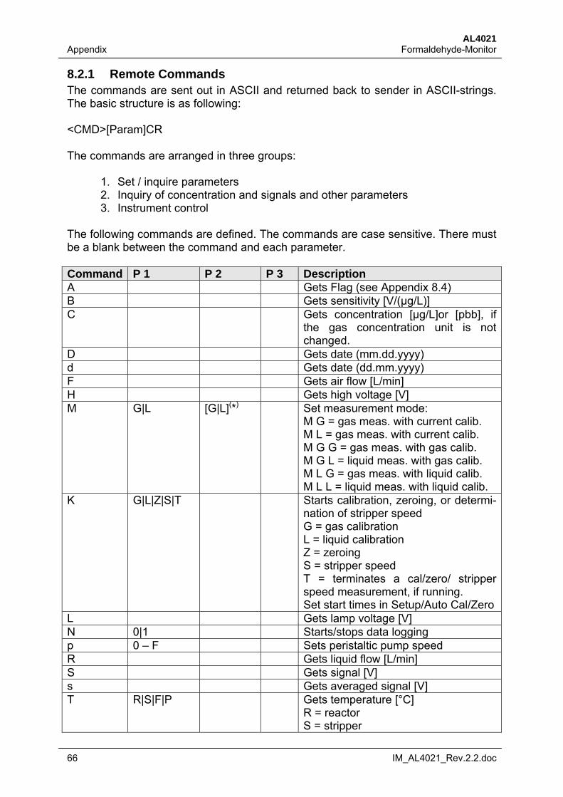
AL4021 Appendix Formaldehyde-Monitor
66 IM_AL4021_Rev.2.2.doc
8.2.1 Remote Commands The commands are sent out in ASCII and returned back to sender in ASCII-strings. The basic structure is as following: <CMD>[Param]CR The commands are arranged in three groups:
1. Set / inquire parameters 2. Inquiry of concentration and signals and other parameters 3. Instrument control
The following commands are defined. The commands are case sensitive. There must be a blank between the command and each parameter. Command P 1 P 2 P 3 Description A Gets Flag (see Appendix 8.4) B Gets sensitivity [V/(µg/L)] C Gets concentration [µg/L]or [pbb], if
the gas concentration unit is not changed.
D Gets date (mm.dd.yyyy) d Gets date (dd.mm.yyyy) F Gets air flow [L/min] H Gets high voltage [V] M G|L [G|L](*) Set measurement mode:
M G = gas meas. with current calib. M L = gas meas. with current calib. M G G = gas meas. with gas calib. M G L = liquid meas. with gas calib. M L G = gas meas. with liquid calib. M L L = liquid meas. with liquid calib.
K G|L|Z|S|T Starts calibration, zeroing, or determi-nation of stripper speed G = gas calibration L = liquid calibration Z = zeroing S = stripper speed T = terminates a cal/zero/ stripper speed measurement, if running. Set start times in Setup/Auto Cal/Zero
L Gets lamp voltage [V] N 0|1 Starts/stops data logging p 0 – F Sets peristaltic pump speed R Gets liquid flow [L/min] S Gets signal [V] s Gets averaged signal [V] T R|S|F|P Gets temperature [°C]
R = reactor S = stripper
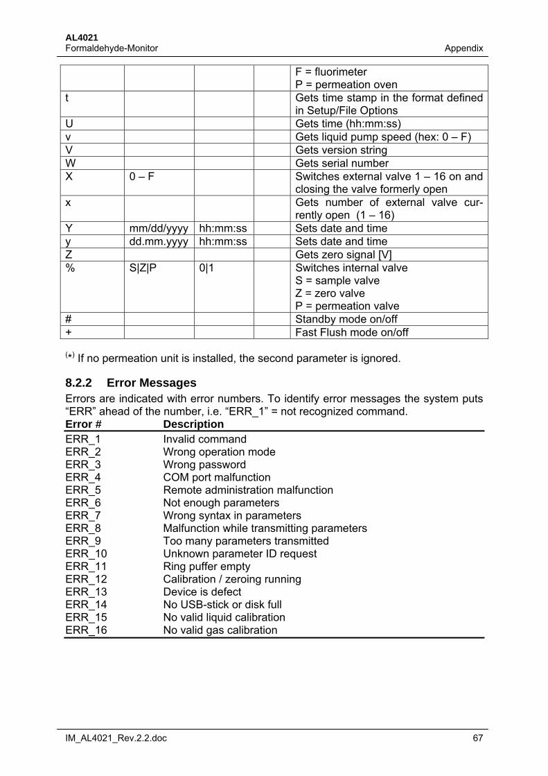
AL4021 Formaldehyde-Monitor Appendix
IM_AL4021_Rev.2.2.doc 67
F = fluorimeter P = permeation oven
t Gets time stamp in the format defined in Setup/File Options
U Gets time (hh:mm:ss) v Gets liquid pump speed (hex: 0 – F) V Gets version string W Gets serial number X 0 – F Switches external valve 1 – 16 on and
closing the valve formerly open x Gets number of external valve cur-
rently open (1 – 16) Y mm/dd/yyyy hh:mm:ss Sets date and time y dd.mm.yyyy hh:mm:ss Sets date and time Z Gets zero signal [V] % S|Z|P 0|1 Switches internal valve
S = sample valve Z = zero valve P = permeation valve
# Standby mode on/off + Fast Flush mode on/off (*) If no permeation unit is installed, the second parameter is ignored.
8.2.2 Error Messages Errors are indicated with error numbers. To identify error messages the system puts “ERR” ahead of the number, i.e. “ERR_1” = not recognized command. Error # Description ERR_1 Invalid command ERR_2 Wrong operation mode ERR_3 Wrong password ERR_4 COM port malfunction ERR_5 Remote administration malfunction ERR_6 Not enough parameters ERR_7 Wrong syntax in parameters ERR_8 Malfunction while transmitting parameters ERR_9 Too many parameters transmitted ERR_10 Unknown parameter ID request ERR_11 Ring puffer empty ERR_12 Calibration / zeroing running ERR_13 Device is defect ERR_14 No USB-stick or disk full ERR_15 No valid liquid calibration ERR_16 No valid gas calibration
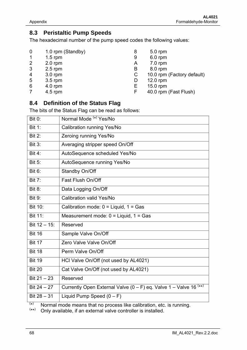
AL4021 Appendix Formaldehyde-Monitor
68 IM_AL4021_Rev.2.2.doc
8.3 Peristaltic Pump Speeds The hexadecimal number of the pump speed codes the following values: 0 1.0 rpm (Standby) 8 5.0 rpm 1 1.5 rpm 9 6.0 rpm 2 2.0 rpm A 7.0 rpm 3 2.5 rpm B 8.0 rpm 4 3.0 rpm C 10.0 rpm (Factory default) 5 3.5 rpm D 12.0 rpm 6 4.0 rpm E 15.0 rpm 7 4.5 rpm F 40.0 rpm (Fast Flush)
8.4 Definition of the Status Flag The bits of the Status Flag can be read as follows:
Bit 0: Normal Mode (*) Yes/No
Bit 1: Calibration running Yes/No
Bit 2: Zeroing running Yes/No
Bit 3: Averaging stripper speed On/Off
Bit 4: AutoSequence scheduled Yes/No
Bit 5: AutoSequence running Yes/No
Bit 6: Standby On/Off
Bit 7: Fast Flush On/Off
Bit 8: Data Logging On/Off
Bit 9: Calibration valid Yes/No
Bit 10: Calibration mode: 0 = Liquid, 1 = Gas
Bit 11: Measurement mode: 0 = Liquid, 1 = Gas
Bit 12 – 15: Reserved
Bit 16 Sample Valve On/Off
Bit 17 Zero Valve Valve On/Off
Bit 18 Perm Valve On/Off
Bit 19 HCl Valve On/Off (not used by AL4021)
Bit 20 Cat Valve On/Off (not used by AL4021)
Bit 21 – 23 Reserved
Bit 24 – 27 Currently Open External Valve (0 – F) eq. Valve 1 – Valve 16 (**)
Bit 28 – 31 Liquid Pump Speed (0 – F) (*) Normal mode means that no process like calibration, etc. is running. (**) Only available, if an external valve controller is installed.

AL4021 Formaldehyde-Monitor Appendix
IM_AL4021_Rev.2.2.doc 69