Embed Size (px)
Citation preview
INSTALLATION MANUAL
Total Heat ExchangerHRV (Heat Reclaim Ventilation)
(Ceiling mounted duct type)
العربیة
Manuel D'installationEchangeur de chaleur totale Unité
Installation ManualHeat Reclaim Ventilation
Руководство По МонтажуВентиляция с регенерацией тепла
كتیب تعلیمات التشغیلتھویة استعادة الحرارة
VAM350FA5 VAM500FA5 VAM650FA5 VAM800FA5VAM1000FA5 VAM1500FA5 VAM2000FA5
Montaj KılavuzuIsı Geri Kazanım Havalandırma Türkçe
Русский
Français
English
1
1
4
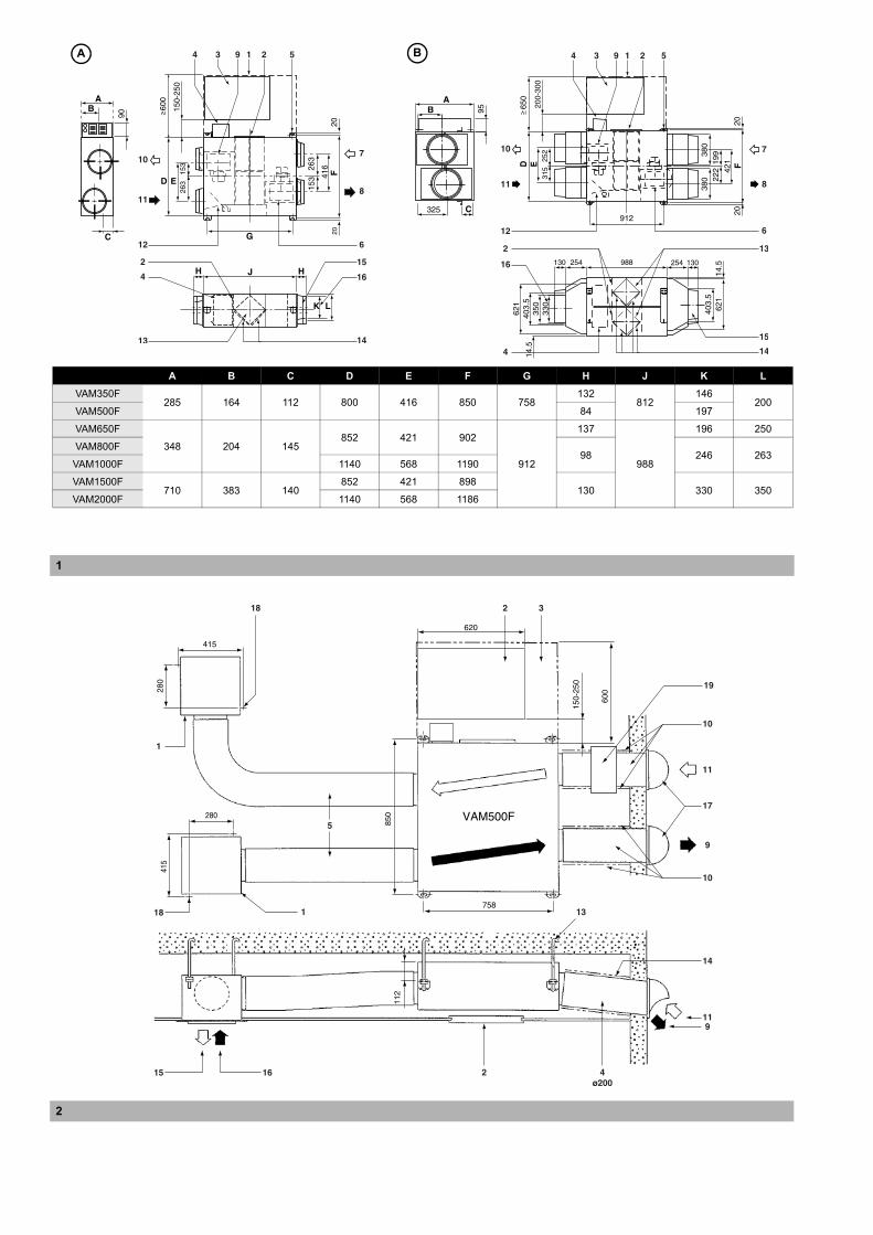
A B C D E F G H J K L
VAM350F285 164 112 800 416 850 758
132812
146200
VAM500F 84 197
VAM650F
348 204 145852 421 902
912
137
988
196 250
VAM800F98 246 263
VAM1000F 1140 568 1190
VAM1500F710 383 140
852 421 898130 330 350
VAM2000F 1140 568 1186
A B
2
2
3
3
4
4
Contents Page
Safety considerations ........................................................................ 1
Dimensions........................................................................................ 2
Installation ......................................................................................... 2
System configuration ......................................................................... 5
Electric wiring .................................................................................... 7
Test run............................................................................................ 21
Wiring diagram ................................................................................ 22
Thank you for purchasing this Daikin HRV.
The original instructions are written in English. All other languagesare translations of the original instructions.
Safety considerations
Please read these "Safety considerations" carefully before installingair conditioning equipment and be sure to install it correctly. Aftercompleting the installation, make sure that the unit operates properlyduring the start-up operation. Please instruct the customer on how tooperate the unit and keep it maintained.
Also, inform customers that they should store this installation manualalong with the operation manual for future reference.
This air conditioner comes under the term “appliances not accessibleto the general public”.
Meaning of warning and caution symbols
VAM350F VAM800F VAM1500FVAM500F VAM1000F VAM2000FVAM650F
Total Heat Exchanger HRV (Heat Reclaim Ventilation) Installation manual
HRV – Heat Reclaim Ventilation
Please read this installation manual carefully and install theunit properly to keep it at full capacity for a long time.
Please prepare some necessary parts, for example roundhoods, air suction/discharge grilles etc., before theinstallation of the unit.
WARNING Failure to follow these instructions properly mayresult in personal injury or loss of life.
CAUTION Failure to observe these instructions properlymay result in property damage or personalinjury, which may be serious depending on thecircumstances.
WARNING Never inspect or service the unit by
yourself.Ask a qualified service person toperform this work.
Electric shock may result. Beforeservicing the unit, always shut offpower.
Persons servicing the unit arerequired to wear gloves.
All wiring must be performed by anauthorized electrician and mustcomply with the applicablelegislation.
Always use the air filter.If the air filter is not used, heatexchange elements will be clogged,possibly causing poor performanceand subsequent failure.
Do not change operations suddenly.It can result not only in malfunctionbut also failure of switches or relaysin the body.
This appliance is not intended foruse by persons (including children)with reduced physical, sensory ormental capabilities, or lack ofexperience and knowledge, unlessthey have been given supervision orinstruction concerning use of theappliance by a person responsiblefor their safety.Children should be supervised toensure that they do not play with theappliance.
Do not use an HRV or an airsuction/discharge grille in thefollowing places:- Places such as machinery plants
and chemical plants where gas,which contains noxius gas orcorrosive components ofmaterials such as acid, alkali,organic solvent and paint, isgenerated.
- Places such as bathroomssubjected to moisture.Electric leak or electric shock andother failure can be caused.
VAM350~2000FATotal Heat ExchangerHRV (Heat Reclaim Ventilation) 4PW90548-1 (2014.03)
Installation manual
1
Dimensions
(See figure 1 (A = Models 350F~1000F, B = Models 1500F~2000F))
Installation
Installation position
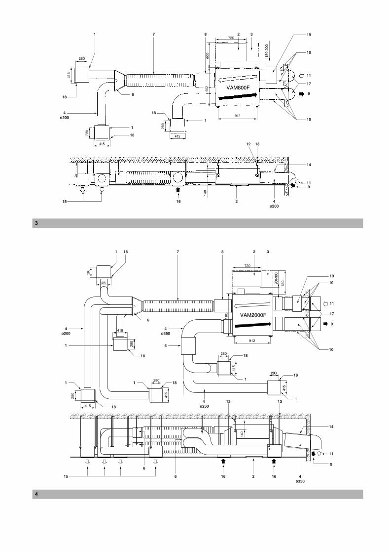
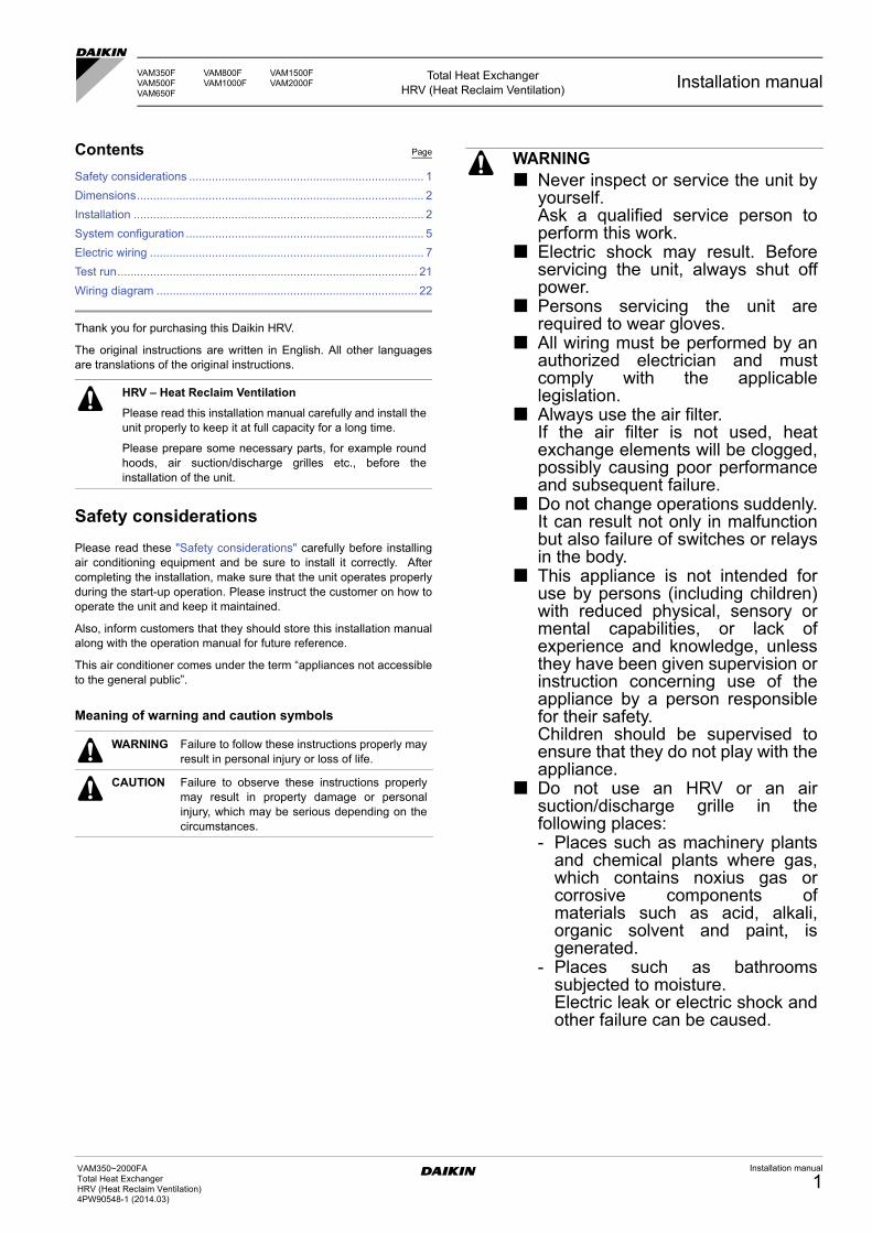
Example of Installation, VAM500F (See figure 2), VAM800F(See figure 3), VAM2000F (See figure 4)
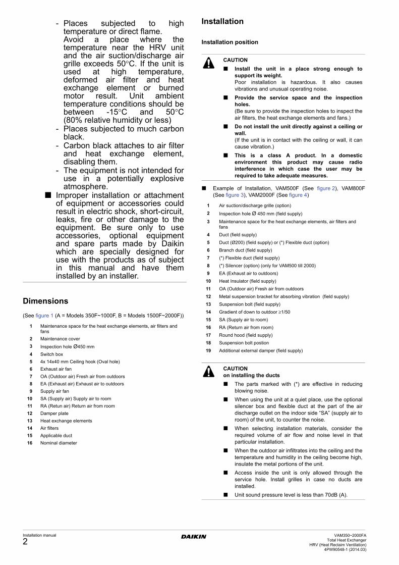
- Places subjected to hightemperature or direct flame.Avoid a place where thetemperature near the HRV unitand the air suction/discharge airgrille exceeds 50°C. If the unit isused at high temperature,deformed air filter and heatexchange element or burnedmotor result. Unit ambienttemperature conditions should bebetween -15°C and 50°C(80% relative humidity or less)
- Places subjected to much carbonblack.
- Carbon black attaches to air filterand heat exchange element,disabling them.
- The equipment is not intended foruse in a potentially explosiveatmosphere.
Improper installation or attachmentof equipment or accessories couldresult in electric shock, short-circuit,leaks, fire or other damage to theequipment. Be sure only to useaccessories, optional equipmentand spare parts made by Daikinwhich are specially designed foruse with the products as of subjectin this manual and have theminstalled by an installer.
1 Maintenance space for the heat exchange elements, air filters and fans
2 Maintenance cover
3 Inspection hole Ø450 mm
4 Switch box
5 4x 14x40 mm Ceiling hook (Oval hole)
6 Exhaust air fan
7 OA (Outdoor air) Fresh air from outdoors
8 EA (Exhaust air) Exhaust air to outdoors
9 Supply air fan
10 SA (Supply air) Supply air to room
11 RA (Retun air) Return air from room
12 Damper plate
13 Heat exchange elements
14 Air filters
15 Applicable duct
16 Nominal diameter
CAUTION
Install the unit in a place strong enough tosupport its weight.Poor installation is hazardous. It also causesvibrations and unusual operating noise.
Provide the service space and the inspectionholes.(Be sure to provide the inspection holes to inspect theair filters, the heat exchange elements and fans.)
Do not install the unit directly against a ceiling orwall.(If the unit is in contact with the ceiling or wall, it cancause vibration.)
This is a class A product. In a domesticenvironment this product may cause radiointerference in which case the user may berequired to take adequate measures.
1 Air suction/discharge grille (option)
2 Inspection hole Ø 450 mm (field supply)
3 Maintenance space for the heat exchange elements, air filters and fans
4 Duct (field supply)
5 Duct (Ø200) (field supply) or (*) Flexible duct (option)
6 Branch duct (field supply)
7 (*) Flexible duct (field supply)
8 (*) Silencer (option) (only for VAM500 till 2000)
9 EA (Exhaust air to outdoors)
10 Heat Insulator (field supply)
11 OA (Outdoor air) Fresh air from outdoors
12 Metal suspension bracket for absorbing vibration (field supply)
13 Suspension bolt (field supply)
14 Gradient of down to outdoor ≥1/50
15 SA (Supply air to room)
16 RA (Return air from room)
17 Round hood (field supply)
18 Suspension bolt postion
19 Additional external damper (field supply)
CAUTIONon installing the ducts
The parts marked with (*) are effective in reducingblowing noise.
When using the unit at a quiet place, use the optionalsilencer box and flexible duct at the part of the airdischarge outlet on the indoor side “SA” (supply air toroom) of the unit, to counter the noise.
When selecting installation materials, consider therequired volume of air flow and noise level in thatparticular installation.
When the outdoor air infiltrates into the ceiling and thetemperature and humidity in the ceiling become high,insulate the metal portions of the unit.
Access inside the unit is only allowed through theservice hole. Install grilles in case no ducts areinstalled.
Unit sound pressure level is less than 70dB (A).
Installation manual
2VAM350~2000FA
Total Heat ExchangerHRV (Heat Reclaim Ventilation)
4PW90548-1 (2014.03)
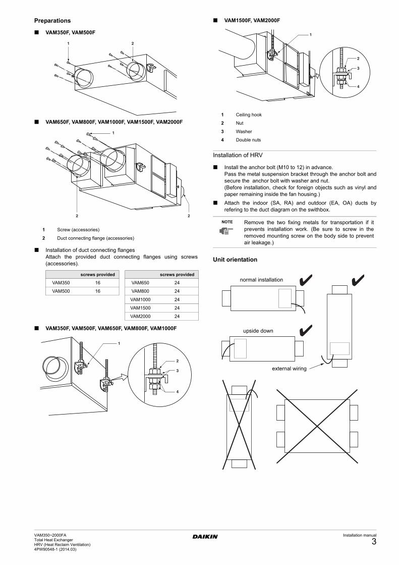
Preparations
VAM350F, VAM500F
VAM650F, VAM800F, VAM1000F, VAM1500F, VAM2000F
Installation of duct connecting flangesAttach the provided duct connecting flanges using screws(accessories).
VAM350F, VAM500F, VAM650F, VAM800F, VAM1000F
VAM1500F, VAM2000F
Installation of HRV
Install the anchor bolt (M10 to 12) in advance.Pass the metal suspension bracket through the anchor bolt andsecure the anchor bolt with washer and nut.(Before installation, check for foreign objects such as vinyl andpaper remaining inside the fan housing.)
Attach the indoor (SA, RA) and outdoor (EA, OA) ducts byrefering to the duct diagram on the swithbox.
Unit orientation
1 Screw (accessories)
2 Duct connecting flange (accessories)
screws provided screws provided
VAM350 16 VAM650 24
VAM500 16 VAM800 24
VAM1000 24
VAM1500 24
VAM2000 24
1 2
1
2 2
1 Ceiling hook
2 Nut
3 Washer
4 Double nuts
NOTE Remove the two fixing metals for transportation if itprevents installation work. (Be sure to screw in theremoved mounting screw on the body side to preventair leakage.)
1
2
3
4
normal installation
upside down
external wiring
VAM350~2000FATotal Heat ExchangerHRV (Heat Reclaim Ventilation) 4PW90548-1 (2014.03)
Installation manual
3
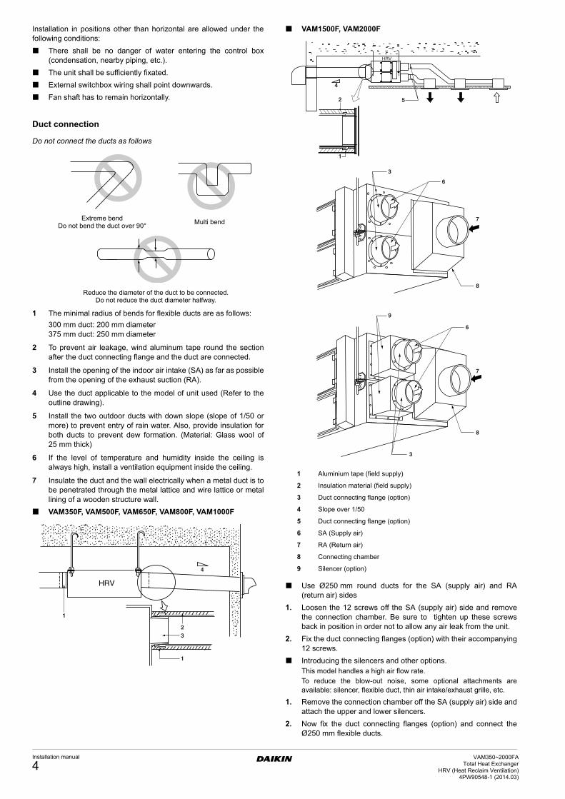
Installation in positions other than horizontal are allowed under thefollowing conditions:
There shall be no danger of water entering the control box(condensation, nearby piping, etc.).
The unit shall be sufficiently fixated.
External switchbox wiring shall point downwards.
Fan shaft has to remain horizontally.
Duct connection
Do not connect the ducts as follows
1 The minimal radius of bends for flexible ducts are as follows:
300 mm duct: 200 mm diameter375 mm duct: 250 mm diameter
2 To prevent air leakage, wind aluminum tape round the sectionafter the duct connecting flange and the duct are connected.
3 Install the opening of the indoor air intake (SA) as far as possiblefrom the opening of the exhaust suction (RA).
4 Use the duct applicable to the model of unit used (Refer to theoutline drawing).
5 Install the two outdoor ducts with down slope (slope of 1/50 ormore) to prevent entry of rain water. Also, provide insulation forboth ducts to prevent dew formation. (Material: Glass wool of25 mm thick)
6 If the level of temperature and humidity inside the ceiling isalways high, install a ventilation equipment inside the ceiling.
7 Insulate the duct and the wall electrically when a metal duct is tobe penetrated through the metal lattice and wire lattice or metallining of a wooden structure wall.
VAM350F, VAM500F, VAM650F, VAM800F, VAM1000F
VAM1500F, VAM2000F
Use Ø250 mm round ducts for the SA (supply air) and RA(return air) sides
1. Loosen the 12 screws off the SA (supply air) side and removethe connection chamber. Be sure to tighten up these screwsback in position in order not to allow any air leak from the unit.
2. Fix the duct connecting flanges (option) with their accompanying12 screws.
Introducing the silencers and other options.This model handles a high air flow rate.
To reduce the blow-out noise, some optional attachments areavailable: silencer, flexible duct, thin air intake/exhaust grille, etc.
1. Remove the connection chamber off the SA (supply air) side andattach the upper and lower silencers.
2. Now fix the duct connecting flanges (option) and connect theØ250 mm flexible ducts.
Extreme bendDo not bend the duct over 90°
Multi bend
Reduce the diameter of the duct to be connected.Do not reduce the duct diameter halfway.
HRV
1
23
1
4
1 Aluminium tape (field supply)
2 Insulation material (field supply)
3 Duct connecting flange (option)
4 Slope over 1/50
5 Duct connecting flange (option)
6 SA (Supply air)
7 RA (Return air)
8 Connecting chamber
9 Silencer (option)
4
2
1
5
HRV
3
6
8
7
7
8
9
6
3
Installation manual
4VAM350~2000FA
Total Heat ExchangerHRV (Heat Reclaim Ventilation)
4PW90548-1 (2014.03)
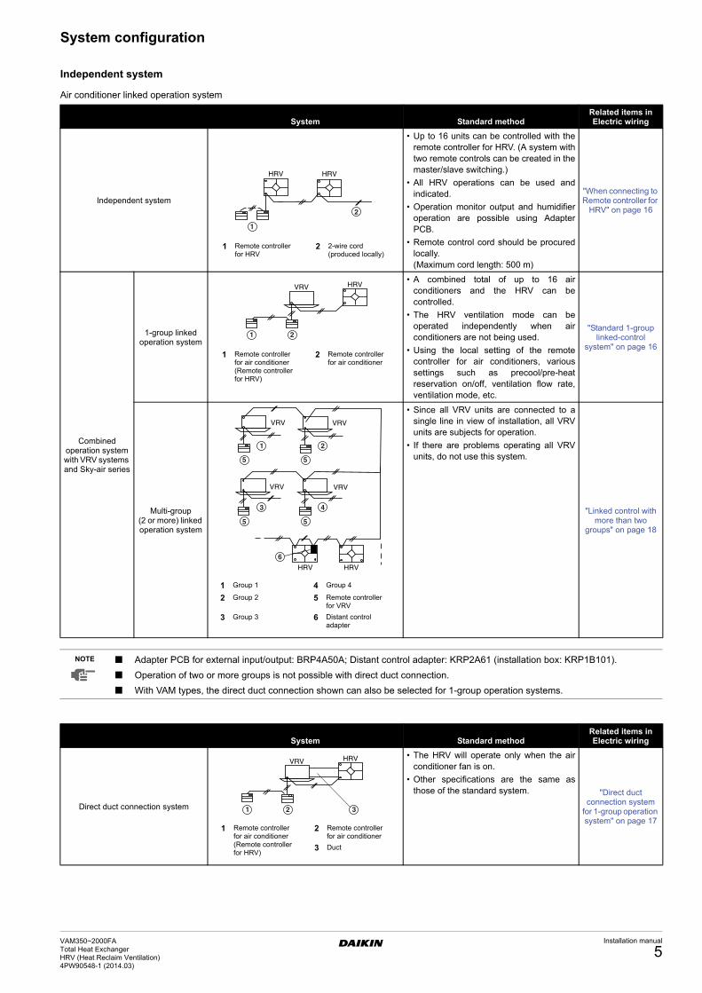
System configuration
Independent system
Air conditioner linked operation system
System Standard methodRelated items in Electric wiring
Independent system
• Up to 16 units can be controlled with theremote controller for HRV. (A system withtwo remote controls can be created in themaster/slave switching.)
• All HRV operations can be used andindicated.
• Operation monitor output and humidifieroperation are possible using AdapterPCB.
• Remote control cord should be procuredlocally.(Maximum cord length: 500 m)
"When connecting to Remote controller for
HRV" on page 16
Combined operation system with VRV systems and Sky-air series
1-group linked operation system
• A combined total of up to 16 airconditioners and the HRV can becontrolled.
• The HRV ventilation mode can beoperated independently when airconditioners are not being used.
• Using the local setting of the remotecontroller for air conditioners, varioussettings such as precool/pre-heatreservation on/off, ventilation flow rate,ventilation mode, etc.
"Standard 1-group linked-control
system" on page 16
Multi-group (2 or more) linked operation system
• Since all VRV units are connected to asingle line in view of installation, all VRVunits are subjects for operation.
• If there are problems operating all VRVunits, do not use this system.
"Linked control with more than two
groups" on page 18
HRV HRV
1
2
1 Remote controller for HRV
2 2-wire cord (produced locally)
VRV HRV
1 2
1 Remote controller for air conditioner(Remote controller for HRV)
2 Remote controller for air conditioner
VRV VRV
VRV VRV
HRV HRV
1 2
5 5
5 5
3 4
6
1 Group 1 4 Group 4
2 Group 2 5 Remote controller for VRV
3 Group 3 6 Distant control adapter
NOTE Adapter PCB for external input/output: BRP4A50A; Distant control adapter: KRP2A61 (installation box: KRP1B101).
Operation of two or more groups is not possible with direct duct connection.
With VAM types, the direct duct connection shown can also be selected for 1-group operation systems.
System Standard methodRelated items in Electric wiring
Direct duct connection system
• The HRV will operate only when the airconditioner fan is on.
• Other specifications are the same asthose of the standard system. "Direct duct
connection system for 1-group operation system" on page 17
VRV HRV
1 2 3
1 Remote controller for air conditioner(Remote controller for HRV)
2 Remote controller for air conditioner
3 Duct
VAM350~2000FATotal Heat ExchangerHRV (Heat Reclaim Ventilation) 4PW90548-1 (2014.03)
Installation manual
5
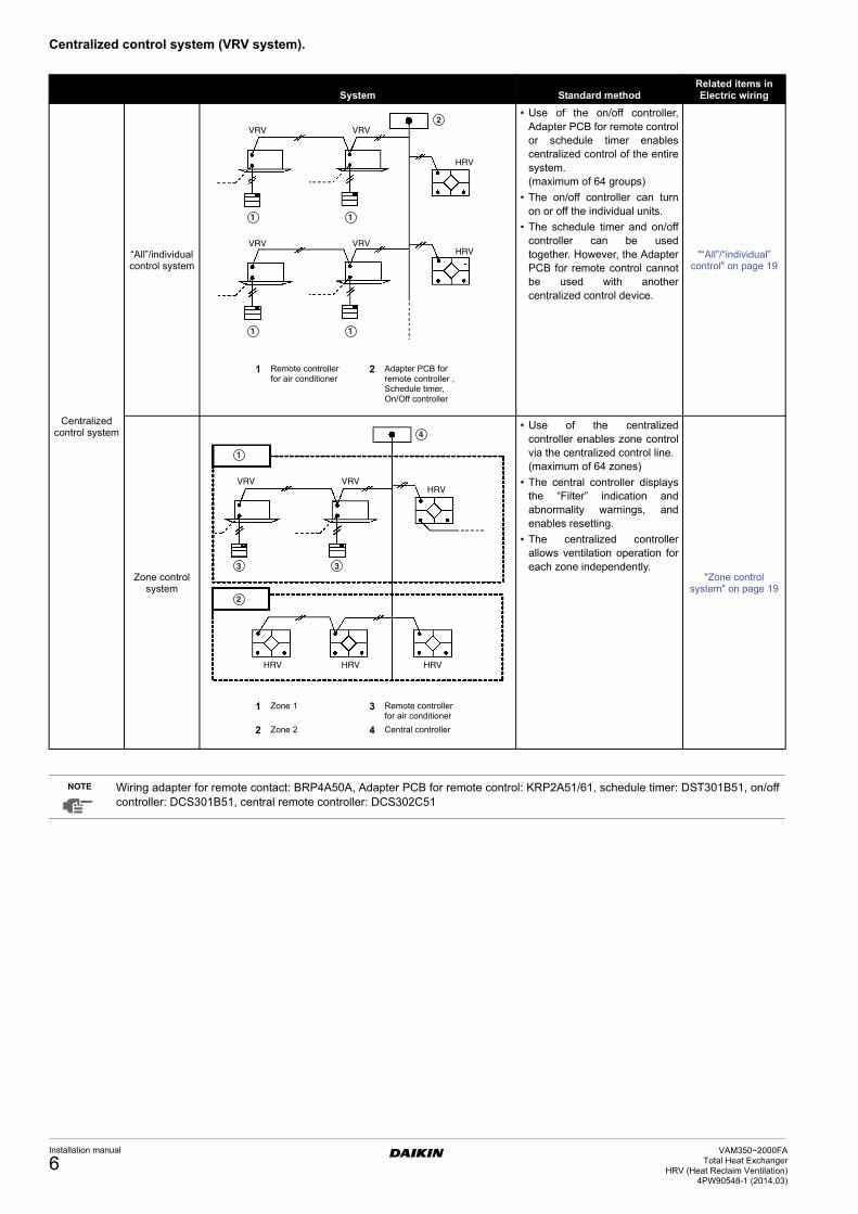
Centralized control system (VRV system).
System Standard methodRelated items in Electric wiring
Centralized control system
“All”/individual control system
• Use of the on/off controller,Adapter PCB for remote controlor schedule timer enablescentralized control of the entiresystem.(maximum of 64 groups)
• The on/off controller can turnon or off the individual units.
• The schedule timer and on/offcontroller can be usedtogether. However, the AdapterPCB for remote control cannotbe used with anothercentralized control device.
"“All”/“individual” control" on page 19
Zone control system
• Use of the centralizedcontroller enables zone controlvia the centralized control line.(maximum of 64 zones)
• The central controller displaysthe “Filter” indication andabnormality warnings, andenables resetting.
• The centralized controllerallows ventilation operation foreach zone independently.
"Zone control system" on page 19
HRV
HRV
VRV VRV
VRV VRV
1 1
1 1
2
1 Remote controller for air conditioner
2 Adapter PCB for remote controller , Schedule timer, On/Off controller
VRV VRV
HRV HRV HRV
HRV
2
1
4
3 3
1 Zone 1 3 Remote controller for air conditioner
2 Zone 2 4 Central controller
NOTE Wiring adapter for remote contact: BRP4A50A, Adapter PCB for remote control: KRP2A51/61, schedule timer: DST301B51, on/offcontroller: DCS301B51, central remote controller: DCS302C51
Installation manual
6VAM350~2000FA
Total Heat ExchangerHRV (Heat Reclaim Ventilation)
4PW90548-1 (2014.03)
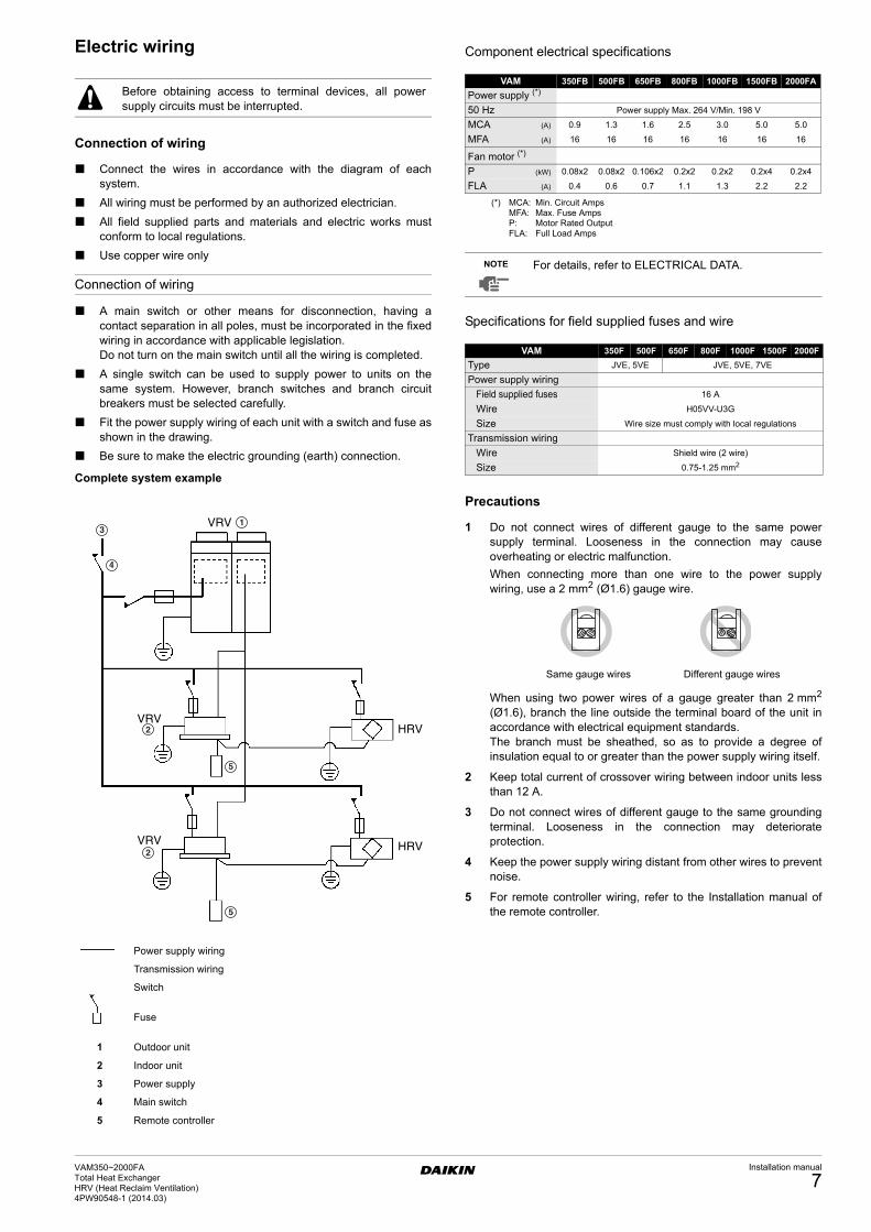
Electric wiring
Connection of wiring
Connect the wires in accordance with the diagram of eachsystem.
All wiring must be performed by an authorized electrician.
All field supplied parts and materials and electric works mustconform to local regulations.
Use copper wire only
Connection of wiring
A main switch or other means for disconnection, having acontact separation in all poles, must be incorporated in the fixedwiring in accordance with applicable legislation.Do not turn on the main switch until all the wiring is completed.
A single switch can be used to supply power to units on thesame system. However, branch switches and branch circuitbreakers must be selected carefully.
Fit the power supply wiring of each unit with a switch and fuse asshown in the drawing.
Be sure to make the electric grounding (earth) connection.
Complete system example
Component electrical specifications
Specifications for field supplied fuses and wire
Precautions
1 Do not connect wires of different gauge to the same powersupply terminal. Looseness in the connection may causeoverheating or electric malfunction.
When connecting more than one wire to the power supplywiring, use a 2 mm2 (Ø1.6) gauge wire.
When using two power wires of a gauge greater than 2 mm2
(Ø1.6), branch the line outside the terminal board of the unit inaccordance with electrical equipment standards.The branch must be sheathed, so as to provide a degree ofinsulation equal to or greater than the power supply wiring itself.
2 Keep total current of crossover wiring between indoor units lessthan 12 A.
3 Do not connect wires of different gauge to the same groundingterminal. Looseness in the connection may deteriorateprotection.
4 Keep the power supply wiring distant from other wires to preventnoise.
5 For remote controller wiring, refer to the Installation manual ofthe remote controller.
Before obtaining access to terminal devices, all powersupply circuits must be interrupted.
Power supply wiring
Transmission wiring
Switch
Fuse
1 Outdoor unit
2 Indoor unit
3 Power supply
4 Main switch
5 Remote controller
VRV
VRV
VRVHRV
HRV
1
2
2
3
4
5
5
VAM 350FB 500FB 650FB 800FB 1000FB 1500FB 2000FAPower supply (*)
(*) MCA: Min. Circuit Amps MFA: Max. Fuse Amps P: Motor Rated Output FLA: Full Load Amps
50 Hz Power supply Max. 264 V/Min. 198 V
MCA (A) 0.9 1.3 1.6 2.5 3.0 5.0 5.0
MFA (A) 16 16 16 16 16 16 16
Fan motor (*)
P (kW) 0.08x2 0.08x2 0.106x2 0.2x2 0.2x2 0.2x4 0.2x4
FLA (A) 0.4 0.6 0.7 1.1 1.3 2.2 2.2
NOTE For details, refer to ELECTRICAL DATA.
VAM 350F 500F 650F 800F 1000F 1500F 2000F
Type JVE, 5VE JVE, 5VE, 7VE
Power supply wiring
Field supplied fuses 16 A
Wire H05VV-U3G
Size Wire size must comply with local regulations
Transmission wiring
Wire Shield wire (2 wire)
Size 0.75-1.25 mm2
Same gauge wires Different gauge wires
VAM350~2000FATotal Heat ExchangerHRV (Heat Reclaim Ventilation) 4PW90548-1 (2014.03)
Installation manual
7
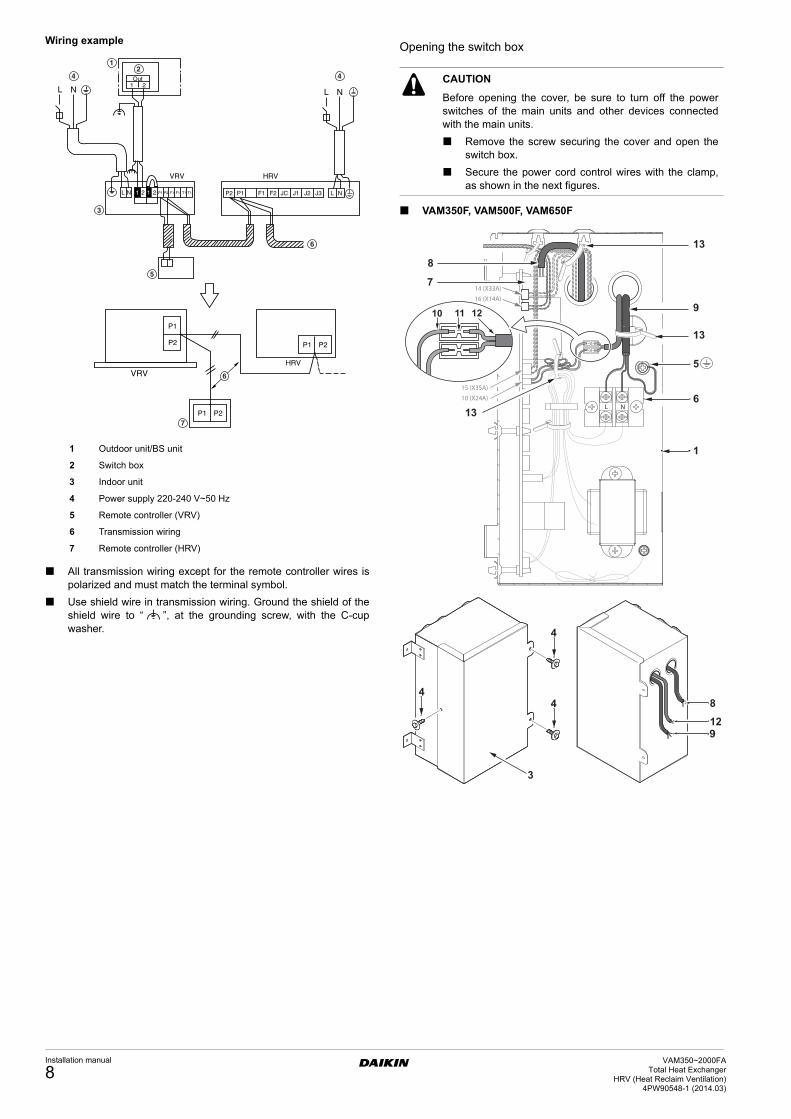
Wiring example
All transmission wiring except for the remote controller wires ispolarized and must match the terminal symbol.
Use shield wire in transmission wiring. Ground the shield of theshield wire to “ ”, at the grounding screw, with the C-cupwasher.
Opening the switch box
VAM350F, VAM500F, VAM650F
VRVHRV
P1
P1
P1
P2 P2
P2
L N1 2Out
VRV HRV
L N
L N 1 12 2 P1 P2 F1 F1 T1 T1 P2 P1 F1 F2 J2 J3JC L NJ1
12
5
3
44
6
7
6
1 Outdoor unit/BS unit
2 Switch box
3 Indoor unit
4 Power supply 220-240 V~50 Hz
5 Remote controller (VRV)
6 Transmission wiring
7 Remote controller (HRV)
CAUTION
Before opening the cover, be sure to turn off the powerswitches of the main units and other devices connectedwith the main units.
Remove the screw securing the cover and open theswitch box.
Secure the power cord control wires with the clamp,as shown in the next figures.
Installation manual
8VAM350~2000FA
Total Heat ExchangerHRV (Heat Reclaim Ventilation)
4PW90548-1 (2014.03)
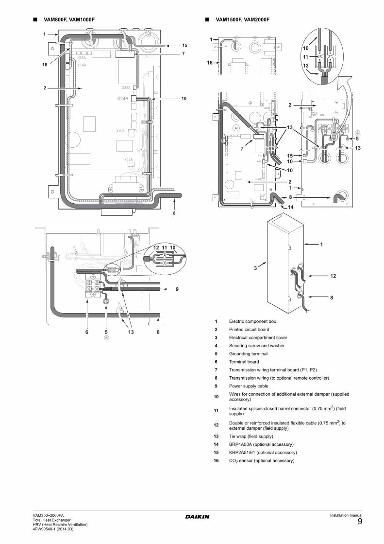
VAM800F, VAM1000F VAM1500F, VAM2000F
1
3
8
12
1110
1010
2
2
8
1
7
12
15
14
1
16
13
13
5
X35A
X24A
X33A
X14A
1 Electric component box
2 Printed circuit board
3 Electrical compartment cover
4 Securing screw and washer
5 Grounding terminal
6 Terminal board
7 Transmission wiring terminal board (P1, P2)
8 Transmission wiring (to optional remote controller)
9 Power supply cable
10Wires for connection of additional external damper (supplied accessory)
11 Insulated splices-closed barrel connector (0.75 mm2) (field supply)
12 Double or reinforced insulated flexible cable (0.75 mm2) to external damper (field supply)
13 Tie wrap (field supply)
14 BRP4A50A (optional accessory)
15 KRP2A51/61 (optional accessory)
16 CO2 sensor (optional accessory)
VAM350~2000FATotal Heat ExchangerHRV (Heat Reclaim Ventilation) 4PW90548-1 (2014.03)
Installation manual
9
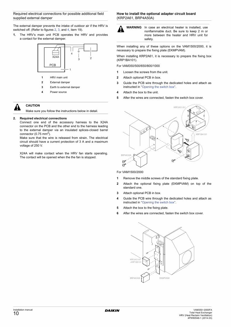
Required electrical connections for possible additional field supplied external damper
The external damper prevents the intake of outdoor air if the HRV isswitched off. (Refer to figures 2, 3, and 4, item 19).
1. The HRV’s main unit PCB operates the HRV and providesa contact for the external damper.
2. Required electrical connectionsConnect one end of the accessory harness to the X24Aconnector on the PCB and the other end to the harness leadingto the external damper via an insulated splices-closed barrelconnector (0.75 mm2).Make sure that the wire is released from strain. The electricalcircuit should have a current protection of 3 A and a maximumvoltage of 250 V.
X24A will make contact when the HRV fan starts operating.The contact will be opened when the the fan is stopped.
How to install the optional adapter circuit board (KRP2A61, BRP4A50A)
When installing any of these options on the VAM1500/2000, it isnecessary to prepare the fixing plate (EKMPVAM).
When installing KRP2A61, it is necessary to prepare the fixing box(KRP1BA101).
For VAM350/500/650/800/1000
1 Loosen the screws from the unit.
2 Attach optional PCB in box.
3 Guide the PCB wire through the dedicated holes and attach asinstructed in "Opening the switch box".
4 Attach the box to the unit.
5 After the wires are connected, fasten the switch box cover.
For VAM1500/2000
1 Remove the middle screws of the standard fixing plate.
2 Attach the optional fixing plate (EKMPVAM) on top of thestandard one.
3 Attach optional PCB in box.
4 Guide the PCB wire through the dedicated holes and attach asinstructed in "Opening the switch box".
5 Attach the box to the fixing plate.
6 After the wires are connected, fasten the switch box cover.
CAUTION
Make sure you follow the instructions below in detail.
1 HRV main unit
2 External damper
3 Earth to external damper
4 Power source
WARNING In case an electrical heater is installed, usenonflammable duct. Be sure to keep 2 m ormore between the heater and HRV unit forsafety.
BRP4A50A
KRP1BA101
KRP2A51/61
BRP4A50A EKMPVAM
KRP2A51/61+KRP1BA101
Installation manual
10VAM350~2000FA
Total Heat ExchangerHRV (Heat Reclaim Ventilation)
4PW90548-1 (2014.03)
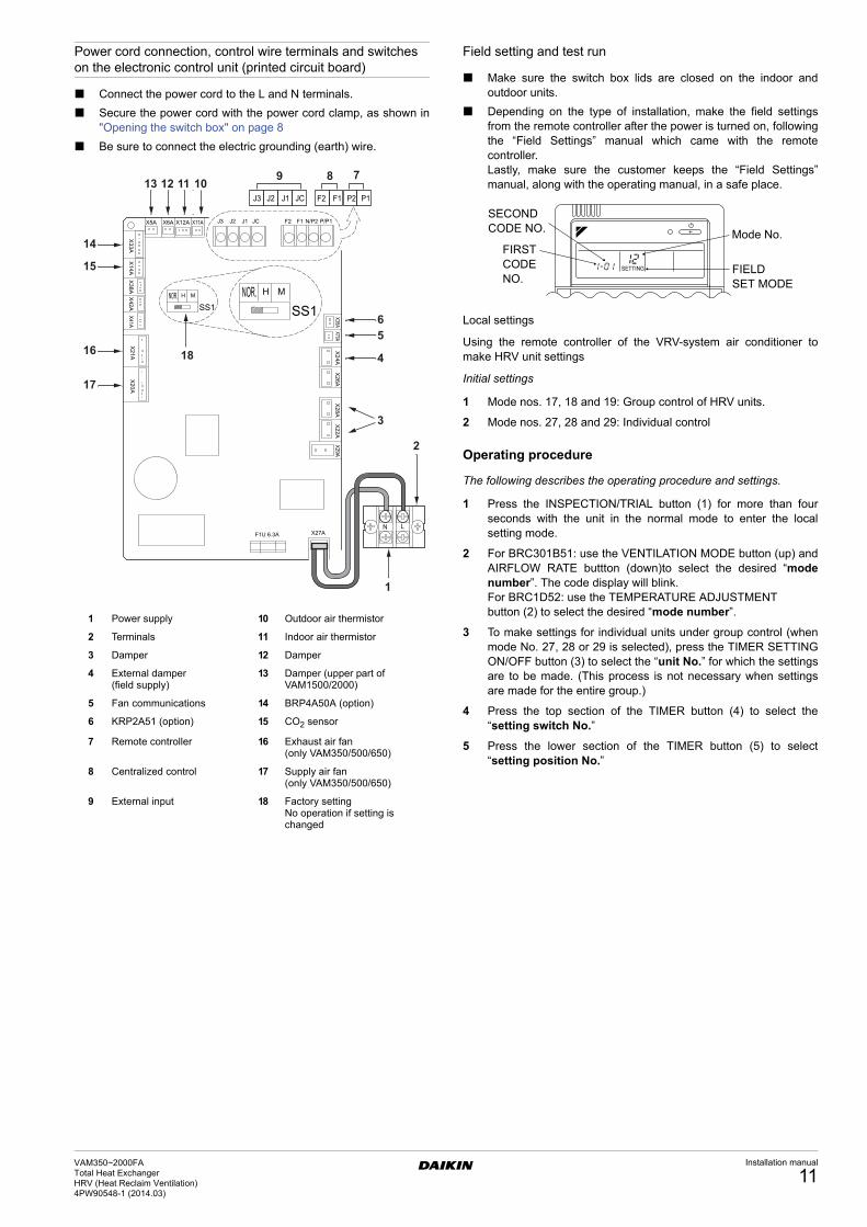
Power cord connection, control wire terminals and switches on the electronic control unit (printed circuit board)
Connect the power cord to the L and N terminals.
Secure the power cord with the power cord clamp, as shown in"Opening the switch box" on page 8
Be sure to connect the electric grounding (earth) wire.
Field setting and test run
Make sure the switch box lids are closed on the indoor andoutdoor units.
Depending on the type of installation, make the field settingsfrom the remote controller after the power is turned on, followingthe “Field Settings” manual which came with the remotecontroller.Lastly, make sure the customer keeps the “Field Settings”manual, along with the operating manual, in a safe place.
Local settings
Using the remote controller of the VRV-system air conditioner tomake HRV unit settings
Initial settings
1 Mode nos. 17, 18 and 19: Group control of HRV units.
2 Mode nos. 27, 28 and 29: Individual control
Operating procedure
The following describes the operating procedure and settings.
1 Press the INSPECTION/TRIAL button (1) for more than fourseconds with the unit in the normal mode to enter the localsetting mode.
2 For BRC301B51: use the VENTILATION MODE button (up) andAIRFLOW RATE buttton (down)to select the desired “modenumber”. The code display will blink.For BRC1D52: use the TEMPERATURE ADJUSTMENT button (2) to select the desired “mode number”.
3 To make settings for individual units under group control (whenmode No. 27, 28 or 29 is selected), press the TIMER SETTINGON/OFF button (3) to select the “unit No.” for which the settingsare to be made. (This process is not necessary when settingsare made for the entire group.)
4 Press the top section of the TIMER button (4) to select the“setting switch No.”
5 Press the lower section of the TIMER button (5) to select“setting position No.”
1 Power supply 10 Outdoor air thermistor
2 Terminals 11 Indoor air thermistor
3 Damper 12 Damper
4 External damper (field supply)
13 Damper (upper part of VAM1500/2000)
5 Fan communications 14 BRP4A50A (option)
6 KRP2A51 (option) 15 CO2 sensor
7 Remote controller 16 Exhaust air fan (only VAM350/500/650)
8 Centralized control 17 Supply air fan (only VAM350/500/650)
9 External input 18 Factory settingNo operation if setting is changed
SETTING
SECOND CODE NO.
FIRST CODE NO.
Mode No.
FIELDSET MODE
VAM350~2000FATotal Heat ExchangerHRV (Heat Reclaim Ventilation) 4PW90548-1 (2014.03)
Installation manual
11
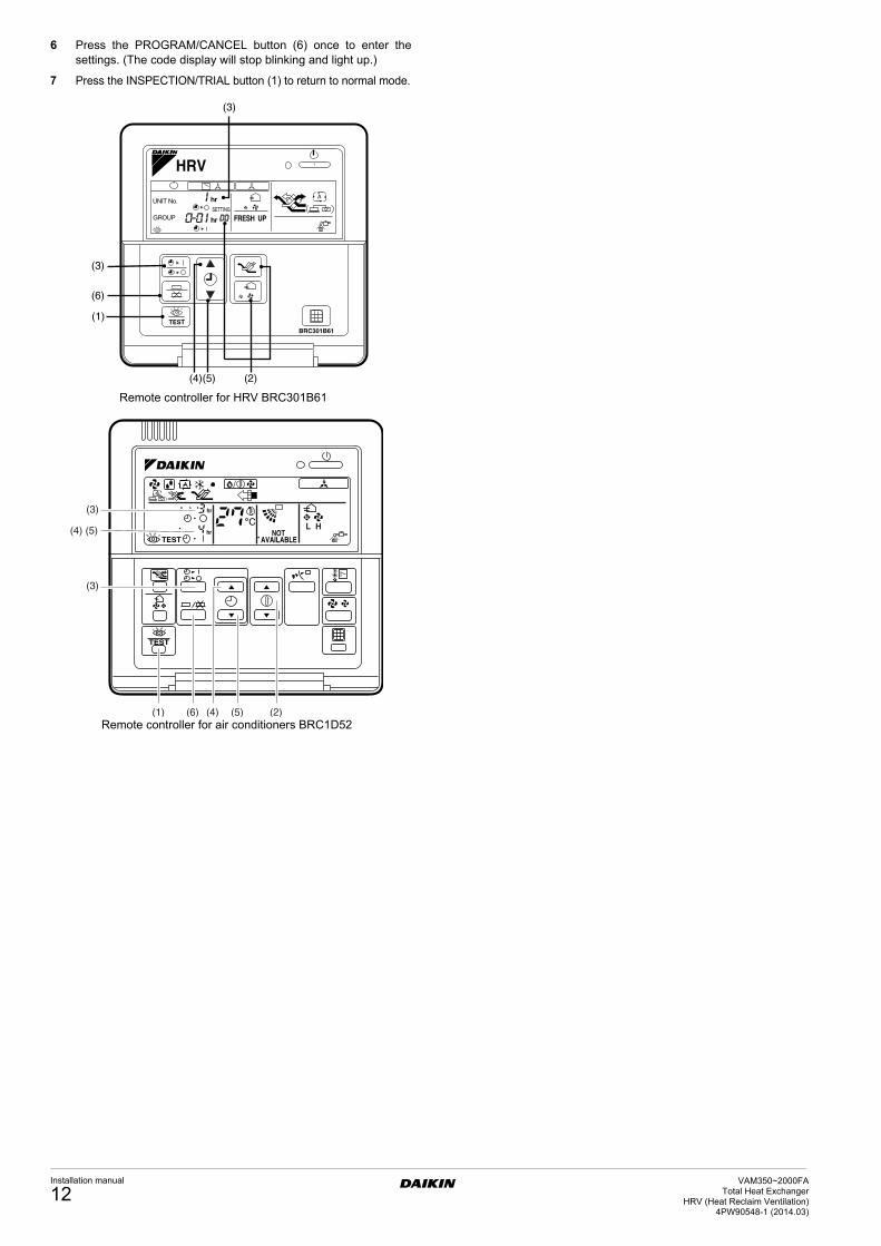
6 Press the PROGRAM/CANCEL button (6) once to enter thesettings. (The code display will stop blinking and light up.)
7 Press the INSPECTION/TRIAL button (1) to return to normal mode.
SETTING
Remote controller for HRV BRC301B61
Remote controller for air conditioners BRC1D52
Installation manual
12VAM350~2000FA
Total Heat ExchangerHRV (Heat Reclaim Ventilation)
4PW90548-1 (2014.03)
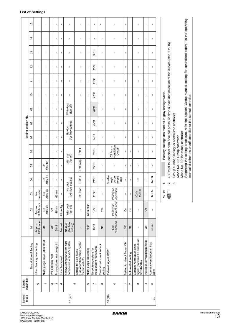
List of Settings
Se
ttin
g m
ode
Se
ttin
g
switc
h N
o.
De
scri
ptio
n o
f Se
ttin
g
Se
ttin
g p
ositi
on N
o.
01
02
03
04
05
06
07
08
09
10
111
21
31
41
5
17
(27
)
0F
ilte
r cl
ean
ing
time
set
ting
App
rox.
2
50
0 ho
urs
App
rox.
1
25
0 ho
urs
No
coun
ting
––
––
––
––
––
––
1N
igh
t p
urg
e ti
me
r (a
fter
sto
p)
Off
On
Afte
r 2
hO
nA
fter
4h
On
Afte
r 6
hO
nA
fter
8h
––
––
––
––
––
2P
re-c
ool
/pre
-he
at
Off
On
––
––
––
––
––
––
–
3P
re-c
ool
/pre
-he
at
time
(min
)3
0m
in4
5m
in6
0m
in–
––
––
––
––
––
–
4In
itia
l fa
n s
pe
ed
No
rmal
Ultr
a-H
igh
––
––
––
––
––
––
–
5
Ye
s/N
o se
ting
for
dire
ct d
uct
conn
ect
ion
with
VR
V s
yste
mN
o d
uct
(A
ir flo
w
setti
ng
)
With
du
ct
(fa
n o
ff)N
o d
uct
(Air
flow
se
ttin
g)W
ith d
uct
(f
an
off)
No
du
ct(A
ir flo
w s
ettin
g)W
ith d
uct
(f
an
off)
––
––
––
Se
ttin
g fo
r co
ld a
rea
s (F
an
op
era
tion
wh
en
he
ate
r th
erm
ost
at
off)
––
T o
ff: s
top
T o
ff: L
T o
ff: s
top
T o
ff: L
––
––
––
6N
igh
t p
urg
e fa
n s
ettin
gH
igh
Ultr
a-H
igh
––
––
––
––
––
––
–
7Ta
rge
t te
mp
era
ture
for
ind
epe
nd
ent
nig
ht
pur
ge
18
°C19
°C20
°C21
°C22
°C23
°C24
°C25
°C26
°C27
°C28
°C2
9°C
30°
C–
–
8C
entr
aliz
ed
zo
ne
inte
rlock
se
ttin
gN
oY
es–
––
––
––
––
––
––
18
(28
)
0
Ext
ern
al s
ign
al J
C/J
2
Last
co
mm
and
Pri
orit
y o
n
ext
ern
al in
pu
tP
rio
rity
on
ope
ratio
n
Dis
able
n
igh
t p
urg
efo
rce
d
stop
–2
4 h
our
s ve
ntila
tion
On
/Off
––
––
––
––
–
1S
etti
ng f
or
dire
ct P
ower
ON
Off
On
––
––
––
––
––
––
–
2A
uto
re
sta
rt s
ettin
gO
ffO
n–
––
–
3E
xte
rna
l he
ate
r/h
umid
ifie
r si
gna
l (b
etw
een
X3
an
d X
4 o
n B
RP
4A
50
A)
––
Onl
y he
atin
gO
n–
––
––
––
––
––
4In
dica
tion
of
ven
tila
tion
mo
deO
nO
ff–
––
––
––
––
––
––
./..
6A
utm
atic
ve
ntil
atio
n a
ir flo
w
tab
leL
ine
ar
–Ta
p A
Tap
B–
––
––
––
––
––
NO
TE
S1
.F
acto
ry s
ettin
gs a
re m
arke
d in
gre
y ba
ckgr
ound
s.
2.
(*)
Ref
er to
tech
nic
al d
ata
book
for
pres
sure
dro
p cu
rve
s an
d s
elec
tion
of fa
n cu
rves
(st
ep 1
to 1
5).
3.
Gro
up n
umbe
r se
tting
for
cent
raliz
ed
con
trol
ler
Mod
e N
o. 0
0: G
roup
con
trol
ler
Mod
e N
o. 3
0: In
divi
dual
con
trol
ler
Reg
ardi
ng
the
sett
ing
proc
edur
e, r
efe
r th
e se
ctio
n “G
roup
num
ber
setti
ng f
or c
entr
aliz
ed c
ontr
ol“
in t
he
oper
atin
gm
anua
l of e
ither
the
on/
off c
ont
rolle
r or
the
cen
tral
con
trol
ler.
VAM350~2000FATotal Heat ExchangerHRV (Heat Reclaim Ventilation) 4PW90548-1 (2014.03)
Installation manual
13
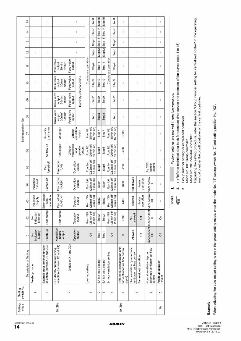
Exa
mp
le
Wh
en a
djus
ting
the
aut
o re
star
t set
ting
to o
n in
the
gro
up s
ettin
g m
ode
, ent
er th
e m
ode
No.
“18
” se
tting
sw
itch
No.
“2”
and
set
ting
posi
tion
No.
“02
”.
Se
ttin
g m
od
eS
ett
ing
sw
itch
No.
De
scri
ptio
n o
f S
ett
ing
Se
ttin
g p
osi
tion
No
.
010
203
04
050
60
70
80
91
011
12
13
14
15
18
(28
)
7F
resh
-up
mo
de
No
In
dic
atio
nS
up
ply
No
Ind
icat
ion
Exh
au
st
Ind
ica
tion
Su
ppl
yIn
dic
atio
nE
xha
ust
––
––
––
––
––
–
8E
xte
rna
l in
put
term
inal
fu
nct
ion
se
lect
ion
(b
etw
ee
n J
1 a
nd
JC
)F
resh
-up
Err
or o
utp
ut
Err
or
ou
tpu
tst
op
op
era
tion
Fo
rce
d of
fF
an
fo
rce
do
ffA
ir flo
w u
pH
um
idify
d
rain
err
or–
––
––
––
–
9
BR
P4
A50
A o
utp
ut s
witc
hin
g se
lect
ion
(b
etw
ee
n X
3 a
nd X
4)
Hu
mid
ifie
r/h
ea
ter
outp
ut
Err
or o
utp
ut
Fa
n o
utp
ut
(L/H
/UH
)F
an o
utp
ut
(H/U
H)
Fa
n o
utp
ut
(UH
)F
an o
utp
ut
Fa
n o
utp
ut
Dra
in v
alve
o
utp
ut
30
min
/12
ho
ur
Dra
in v
alv
e
outp
ut
30m
in/
8ho
ur
Dra
in v
alve
o
utp
ut
30
min
6h
our
Dra
in v
alv
e
outp
ut
30m
in/
4ho
ur
––
––
(b
etw
ee
n X
1 a
nd X
2)
Op
era
tion
ou
tpu
tO
per
atio
n
ou
tput
Op
era
tion
ou
tpu
tO
per
atio
n
ou
tput
Op
era
tion
ou
tpu
t
24h
ou
r ve
ntil
atio
n
and
o
per
atio
n
ou
tpu
t
24
hou
r ve
ntil
atio
n
outp
ut
Fe
ed
va
lve
o
utp
ut
Fe
ed v
alv
e ou
tpu
tF
ee
d v
alv
e
ou
tpu
tF
eed
va
lve
outp
ut
––
––
Hu
mid
ify u
nit
con
ne
ctio
n
19
(29
)
1Lo
w ta
p s
ettin
gO
ffR
un 1
/15
(28
min
off/
2 m
in o
n)
Ru
n 1
/10
(27
min
off/
3 m
in o
n)
Ru
n 1
/6(2
5m
in o
ff/5
min
on
)
Run
1/4
(22
.5m
in o
ff/7
.5 m
in o
n)
Ru
n 1
/3(2
0m
in o
ff/1
0 m
in o
n)
Run
1/2
(15
min
off/
15
min
on
)
Co
ntin
uo
us
op
era
tion
Ste
p1
Ste
p2
Ste
p3
Ste
p4
Ste
p5
Ste
p6
Ste
p7
Ste
p8
2S
A f
an
ste
p s
etti
ng*
Ste
p1
Ste
p2
Ste
p3
Ste
p4
Ste
p5
Ste
p6
Ste
p7
Ste
p8
Ste
p9
Ste
p10
Ste
p11
Ste
p12
Ste
p1
3S
tep1
4S
tep
15
3E
A f
an
ste
p s
etti
ng*
Ste
p1
Ste
p2
Ste
p3
Ste
p4
Ste
p5
Ste
p6
Ste
p7
Ste
p8
Ste
p9
Ste
p10
Ste
p11
Ste
p12
Ste
p1
3S
tep1
4S
tep
15
424
ho
ur v
ent
ilatio
n s
ettin
gO
ffR
un 1
/15
(28
min
off/
2 m
in o
n)
Ru
n 1
/10
(27
min
off/
3 m
in o
n)
Ru
n 1
/6(2
5m
in o
ff/5
min
on
)
Run
1/4
(22
.5m
in o
ff/7
.5 m
in o
n)
Ru
n 1
/3(2
0m
in o
ff/1
0 m
in o
n)
Run
1/2
(15
min
off/
15
min
on
)
Co
ntin
uo
us
op
era
tion
Ste
p1
Ste
p2
Ste
p3
Ste
p4
Ste
p5
Ste
p5
Ste
p7
Ste
p8
7R
efe
ren
ce c
once
ntr
atio
n s
hift
fo
r ve
ntil
atio
n ai
r flo
w c
on
tro
l (p
pm
)0
+2
00+
40
0+
600
–20
0–
40
0–
600
––
––
––
––
8
Sto
p v
en
tila
tion
by
au
tom
atic
ve
ntila
tion
air
flo
w c
ont
rol
Allo
we
dN
ot
al
low
ed
Allo
we
dN
ot a
llow
ed
––
––
––
––
––
–F
an
resi
du
al o
pera
tion
Off
Off
He
ater
op
era
tion
He
ate
r o
per
atio
n
9N
orm
al v
entil
atio
n ta
p on
au
tom
atic
ve
ntil
atio
n ai
r flo
w
cont
rol
Ind
epe
nde
nt
UH
Ind
ep
end
ent
HV
RV
con
tro
lU
HV
RV
co
ntr
ol
H
By
CO
2 se
nsor
co
ntro
l–
––
––
––
––
–
1A
0F
resh
up
op
era
tion
O
n/O
ffO
ffO
n–
––
––
––
––
––
––
NO
TE
S1.
Fac
tory
set
tings
are
mar
ked
in g
rey
back
gro
unds
.
2.(*
) R
efer
to
tech
nica
l dat
a bo
ok fo
r pr
essu
re d
rop
curv
es a
nd
sele
ctio
n o
f fan
cur
ves
(ste
p 1
to 1
5).
3.G
roup
num
ber
setti
ng fo
r ce
ntra
lized
co
ntro
ller
Mod
e N
o. 0
0: G
roup
con
trol
ler
Mod
e N
o. 3
0: In
divi
dual
con
trol
ler
Reg
ard
ing
the
setti
ng p
roce
dure
, re
fer
the
sect
ion
“Gro
up n
umbe
r se
tting
for
cen
tral
ized
con
trol
“ in
the
ope
ratin
gm
anua
l of e
ither
the
on/o
ff co
ntro
ller
or t
he c
ent
ral c
ontr
olle
r.
Installation manual
14VAM350~2000FA
Total Heat ExchangerHRV (Heat Reclaim Ventilation)
4PW90548-1 (2014.03)
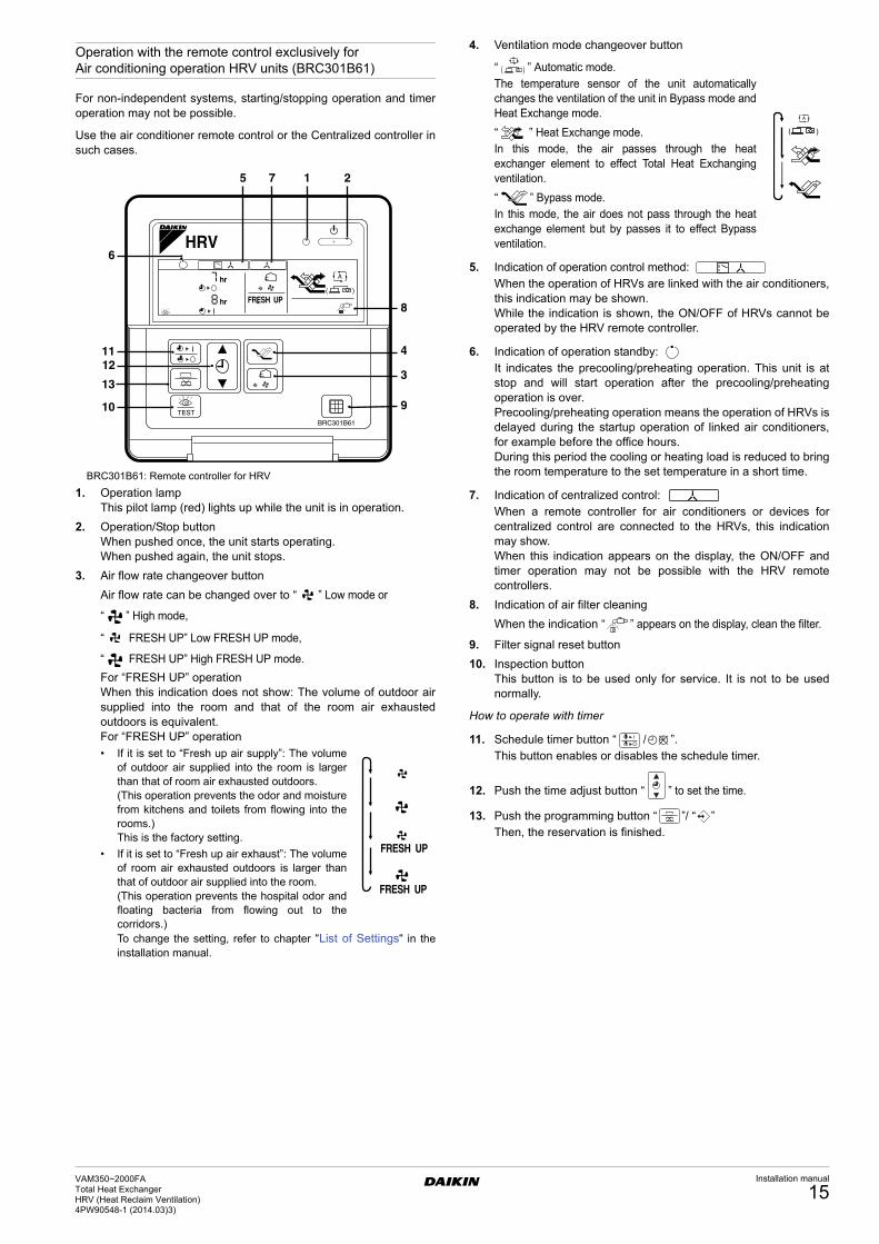
Operation with the remote control exclusively for Air conditioning operation HRV units (BRC301B61)
For non-independent systems, starting/stopping operation and timeroperation may not be possible.
Use the air conditioner remote control or the Centralized controller insuch cases.
BRC301B61: Remote controller for HRV
1. Operation lampThis pilot lamp (red) lights up while the unit is in operation.
2. Operation/Stop buttonWhen pushed once, the unit starts operating.When pushed again, the unit stops.
3. Air flow rate changeover button
Air flow rate can be changed over to “ ” Low mode or
“ ” High mode,
“ FRESH UP” Low FRESH UP mode,
“ FRESH UP” High FRESH UP mode.
For “FRESH UP” operationWhen this indication does not show: The volume of outdoor airsupplied into the room and that of the room air exhaustedoutdoors is equivalent.For “FRESH UP” operation
• If it is set to “Fresh up air supply”: The volumeof outdoor air supplied into the room is largerthan that of room air exhausted outdoors.(This operation prevents the odor and moisturefrom kitchens and toilets from flowing into therooms.)This is the factory setting.
• If it is set to “Fresh up air exhaust”: The volumeof room air exhausted outdoors is larger thanthat of outdoor air supplied into the room.(This operation prevents the hospital odor andfloating bacteria from flowing out to thecorridors.)To change the setting, refer to chapter “List of Settings“ in theinstallation manual.
4. Ventilation mode changeover button
“ ” Automatic mode.The temperature sensor of the unit automaticallychanges the ventilation of the unit in Bypass mode andHeat Exchange mode.
“ ” Heat Exchange mode.In this mode, the air passes through the heatexchanger element to effect Total Heat Exchangingventilation.
“ ” Bypass mode.In this mode, the air does not pass through the heatexchange element but by passes it to effect Bypassventilation.
5. Indication of operation control method:When the operation of HRVs are linked with the air conditioners,this indication may be shown.While the indication is shown, the ON/OFF of HRVs cannot beoperated by the HRV remote controller.
6. Indication of operation standby:It indicates the precooling/preheating operation. This unit is atstop and will start operation after the precooling/preheatingoperation is over.Precooling/preheating operation means the operation of HRVs isdelayed during the startup operation of linked air conditioners,for example before the office hours.During this period the cooling or heating load is reduced to bringthe room temperature to the set temperature in a short time.
7. Indication of centralized control:When a remote controller for air conditioners or devices forcentralized control are connected to the HRVs, this indicationmay show.When this indication appears on the display, the ON/OFF andtimer operation may not be possible with the HRV remotecontrollers.
8. Indication of air filter cleaning
When the indication “ ” appears on the display, clean the filter.
9. Filter signal reset button
10. Inspection buttonThis button is to be used only for service. It is not to be usednormally.
How to operate with timer
11. Schedule timer button “ / ”.This button enables or disables the schedule timer.
12. Push the time adjust button “ ” to set the time.
13. Push the programming button “ ”/ “ ”Then, the reservation is finished.
( )
BRC301B61
A
HRV
TEST
FRESH UP
hr
hr
6
8
4
3
9
5 7 1 2
11
13
10
12
FRESH UP
FRESH UP
A
( (
A
( (
VAM350~2000FATotal Heat ExchangerHRV (Heat Reclaim Ventilation) 4PW90548-1 (2014.03)3)
Installation manual
15
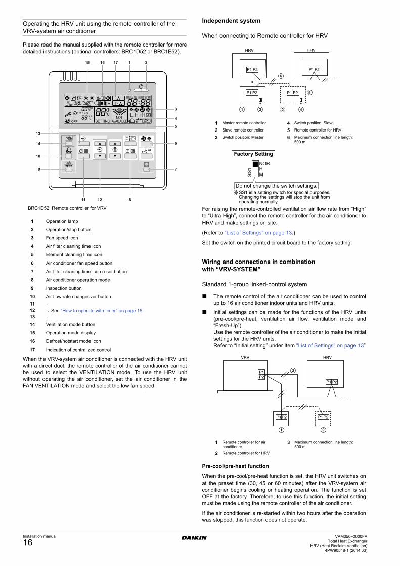
Operating the HRV unit using the remote controller of the VRV-system air conditioner
Please read the manual supplied with the remote controller for moredetailed instructions (optional controllers: BRC1D52 or BRC1E52).
BRC1D52: Remote controller for VRV
When the VRV-system air conditioner is connected with the HRV unitwith a direct duct, the remote controller of the air conditioner cannotbe used to select the VENTILATION mode. To use the HRV unitwithout operating the air conditioner, set the air conditioner in theFAN VENTILATION mode and select the low fan speed.
Independent system
When connecting to Remote controller for HRV
For raising the remote-controlled ventilation air flow rate from “High”to “Ultra-High”, connect the remote controller for the air-conditioner toHRV and make settings on site.
(Refer to "List of Settings" on page 13.)
Set the switch on the printed circuit board to the factory setting.
Wiring and connections in combination with “VRV-SYSTEM”
Standard 1-group linked-control system
The remote control of the air conditioner can be used to controlup to 16 air conditioner indoor units and HRV units.
Initial settings can be made for the functions of the HRV units(pre-cool/pre-heat, ventilation air flow, ventilation mode and“Fresh-Up”).Use the remote controller of the air conditioner to make the initialsettings for the HRV units.Refer to “Initial setting” under Item "List of Settings" on page 13”
Pre-cool/pre-heat function
When the pre-cool/pre-heat function is set, the HRV unit switches onat the preset time (30, 45 or 60 minutes) after the VRV-system airconditioner begins cooling or heating operation. The function is setOFF at the factory. Therefore, to use this function, the initial settingmust be made using the remote controller of the air conditioner.
If the air conditioner is re-started within two hours after the operationwas stopped, this function does not operate.
1 Operation lamp
2 Operation/stop button
3 Fan speed icon
4 Air filter cleaning time icon
5 Element cleaning time icon
6 Air conditioner fan speed button
7 Air filter cleaning time icon reset button
8 Air conditioner operation mode
9 Inspection button
10 Air flow rate changeover button
11
See "How to operate with timer" on page 151213
14 Ventilation mode button
15 Operation mode display
16 Defrost/hotstart mode icon
17 Indication of centralized control
15 17 1 216
3
4
5
6
7
81211
9
10
14
13
1 Master remote controller 4 Switch position: Slave
2 Slave remote controller 5 Remote controller for HRV
3 Switch position: Master 6 Maximum connection line length: 500 m
SS1 is a setting switch for special purposes. Changing the settings will stop the unit from operating normally.
Factory Setting
SS
1
NORHM
Do not change the switch settings.
P1P2
P1P2 P1P2
P1 P2
VRV HRV
1 2
3
1 Remote controller for air conditioner
3 Maximum connection line length: 500 m
2 Remote controller for HRV
Installation manual
16VAM350~2000FA
Total Heat ExchangerHRV (Heat Reclaim Ventilation)
4PW90548-1 (2014.03)
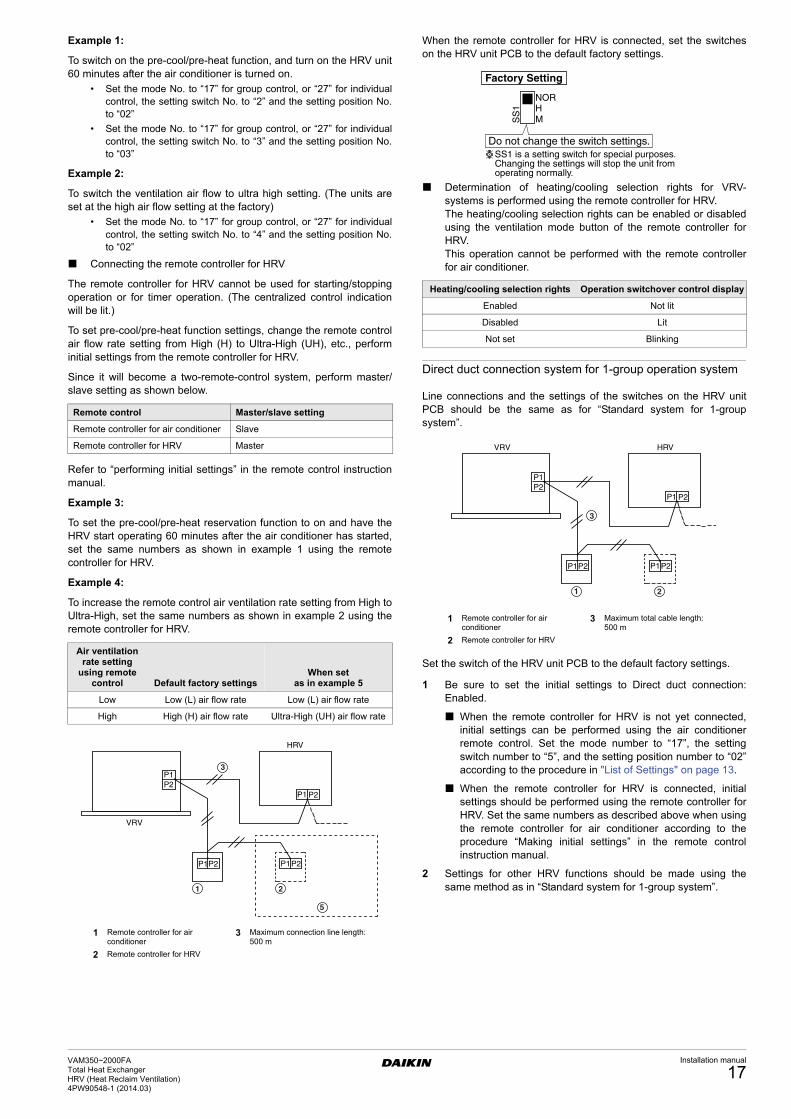
Example 1:
To switch on the pre-cool/pre-heat function, and turn on the HRV unit60 minutes after the air conditioner is turned on.
• Set the mode No. to “17” for group control, or “27” for individualcontrol, the setting switch No. to “2” and the setting position No.to “02”
• Set the mode No. to “17” for group control, or “27” for individualcontrol, the setting switch No. to “3” and the setting position No.to “03”
Example 2:
To switch the ventilation air flow to ultra high setting. (The units areset at the high air flow setting at the factory)
• Set the mode No. to “17” for group control, or “27” for individualcontrol, the setting switch No. to “4” and the setting position No.to “02”
Connecting the remote controller for HRV
The remote controller for HRV cannot be used for starting/stoppingoperation or for timer operation. (The centralized control indicationwill be lit.)
To set pre-cool/pre-heat function settings, change the remote controlair flow rate setting from High (H) to Ultra-High (UH), etc., performinitial settings from the remote controller for HRV.
Since it will become a two-remote-control system, perform master/slave setting as shown below.
Refer to “performing initial settings” in the remote control instructionmanual.
Example 3:
To set the pre-cool/pre-heat reservation function to on and have theHRV start operating 60 minutes after the air conditioner has started,set the same numbers as shown in example 1 using the remotecontroller for HRV.
Example 4:
To increase the remote control air ventilation rate setting from High toUltra-High, set the same numbers as shown in example 2 using theremote controller for HRV.
When the remote controller for HRV is connected, set the switcheson the HRV unit PCB to the default factory settings.
Determination of heating/cooling selection rights for VRV-systems is performed using the remote controller for HRV.The heating/cooling selection rights can be enabled or disabledusing the ventilation mode button of the remote controller forHRV.This operation cannot be performed with the remote controllerfor air conditioner.
Direct duct connection system for 1-group operation system
Line connections and the settings of the switches on the HRV unitPCB should be the same as for “Standard system for 1-groupsystem”.
Set the switch of the HRV unit PCB to the default factory settings.
1 Be sure to set the initial settings to Direct duct connection:Enabled.
When the remote controller for HRV is not yet connected,initial settings can be performed using the air conditionerremote control. Set the mode number to “17”, the settingswitch number to “5”, and the setting position number to “02”according to the procedure in "List of Settings" on page 13.
When the remote controller for HRV is connected, initialsettings should be performed using the remote controller forHRV. Set the same numbers as described above when usingthe remote controller for air conditioner according to theprocedure “Making initial settings” in the remote controlinstruction manual.
2 Settings for other HRV functions should be made using thesame method as in “Standard system for 1-group system”.
Remote control Master/slave setting
Remote controller for air conditioner Slave
Remote controller for HRV Master
Air ventilation rate setting
using remote control Default factory settings
When set as in example 5
Low Low (L) air flow rate Low (L) air flow rate
High High (H) air flow rate Ultra-High (UH) air flow rate
P1P2
P1P2 P1P2
P1 P2
VRV
1 2
5
3
HRV
1 Remote controller for air conditioner
3 Maximum connection line length: 500 m
2 Remote controller for HRV
Heating/cooling selection rights Operation switchover control display
Enabled Not lit
Disabled Lit
Not set Blinking
SS1 is a setting switch for special purposes. Changing the settings will stop the unit from operating normally.
Factory Setting
SS
1
NORHM
Do not change the switch settings.
P1P2
P1P2 P1P2
P1 P2
VRV
1 2
3
HRV
1 Remote controller for air conditioner
3 Maximum total cable length: 500 m
2 Remote controller for HRV
VAM350~2000FATotal Heat ExchangerHRV (Heat Reclaim Ventilation) 4PW90548-1 (2014.03)
Installation manual
17
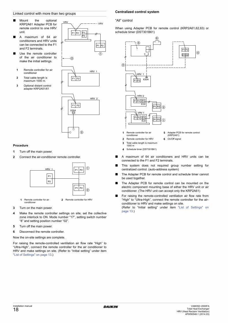
Linked control with more than two groups
Mount the optionalKRP2A61 Adapter PCB forremote control to one HRVunit.
A maximum of 64 airconditioners and HRV unitscan be connected to the F1and F2 terminals.
Use the remote controllerof the air conditioner tomake the initial settings.
Procedure
1 Turn off the main power.
2 Connect the air-conditioner remote controller.
3 Turn on the main power.
4 Make the remote controller settings on site; set the collectivezone interlock to ON. Mode number “17”, setting switch number“8” and setting position number “02”.
5 Turn off the main power.
6 Disconnect the remote controller.
Now the on-site settings are complete.
For raising the remote-controlled ventilation air flow rate “High” to“Ultra-High”, connect the remote controller for the air conditioner toHRV and make settings on site. (Refer to “Initial setting” under item"List of Settings" on page 13.)
Centralized control system
“All” control
When using Adapter PCB for remote control (KRP2A61,62,63) orschedule timer (DST301B61)
A maximum of 64 air conditioners and HRV units can beconnected to the F1 and F2 terminals.
This system does not required group number setting forcentralized control. (auto-address system)
The Adapter PCB for remote control and schedule timer cannotbe used together.
The Adapter PCB for remote control can be mounted on theelectric component mounting base of either the HRV unit or airconditioner. (The HRV unit can accept only the KRP2A61)
For raising the remote-controlled ventilation air flow rate from“High” to “Ultra-High”, connect the remote controller for the air-conditioner to HRV and make settings on site.(Refer to “Initial setting” under item "List of Settings" onpage 13.)
1 Remote controller for air conditioner
2 Total cable length is maximum 1000 m.
3 Optional distant control adapter KRP2A51/61
VRVVRV
HRV 1
HRV 2
X35A
F1 F2 P1P2
P1 P2
F1 F2
F1 F2
1
2
3
P1
P2
P1 P2
P1 P2
HRV 1 1
2
1 Remote controller for air conditioner
2 Remote controller for HRV
HRV 1
X35A
HRV 2
VRV 1
F1 F2
D1 D2
F1 F2
F1 F2
F1 F2 P1P2 P1 P2
P1P2
P1 P2
1
2
6
3
4
5
1 Remote controller for air conditioner
5 Adapter PCB for remote control (KRP2A61)
2 Remote controller for HRV 6 On/Off signal
3 Total cable length is maximum 1000 m
4 Schedule timer (DST301B61)
Installation manual
18VAM350~2000FA
Total Heat ExchangerHRV (Heat Reclaim Ventilation)
4PW90548-1 (2014.03)
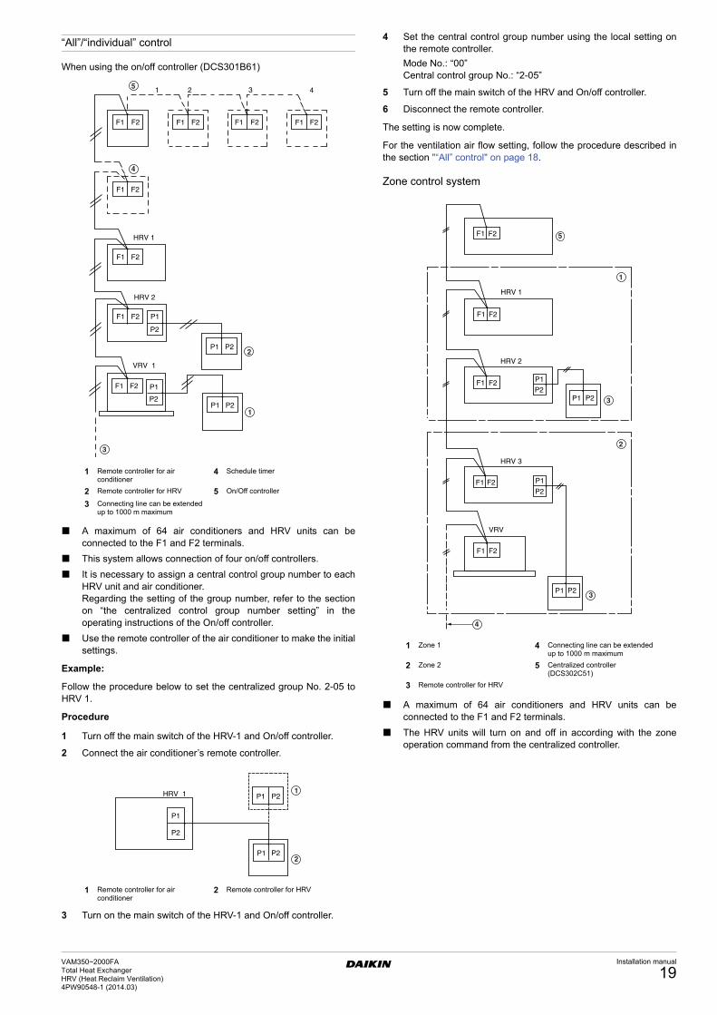
“All”/“individual” control
When using the on/off controller (DCS301B61)
A maximum of 64 air conditioners and HRV units can beconnected to the F1 and F2 terminals.
This system allows connection of four on/off controllers.
It is necessary to assign a central control group number to eachHRV unit and air conditioner.Regarding the setting of the group number, refer to the sectionon “the centralized control group number setting” in theoperating instructions of the On/off controller.
Use the remote controller of the air conditioner to make the initialsettings.
Example:
Follow the procedure below to set the centralized group No. 2-05 toHRV 1.
Procedure
1 Turn off the main switch of the HRV-1 and On/off controller.
2 Connect the air conditioner’s remote controller.
3 Turn on the main switch of the HRV-1 and On/off controller.
4 Set the central control group number using the local setting onthe remote controller.
Mode No.: “00”Central control group No.: “2-05”
5 Turn off the main switch of the HRV and On/off controller.
6 Disconnect the remote controller.
The setting is now complete.
For the ventilation air flow setting, follow the procedure described inthe section "“All” control" on page 18.
Zone control system
A maximum of 64 air conditioners and HRV units can beconnected to the F1 and F2 terminals.
The HRV units will turn on and off in according with the zoneoperation command from the centralized controller.
1 2 3 4
F1 F2 F1 F2 F1 F2 F1 F2
F1 F2
F1 F2
F1 F2
F1 F2
P1
P2
P1
P2
P1 P2
P1 P2
HRV 1
HRV 2
VRV 1
1
2
5
3
4
1 Remote controller for air conditioner
4 Schedule timer
2 Remote controller for HRV 5 On/Off controller
3 Connecting line can be extended up to 1000 m maximum
P1
P2
P1 P2
P1 P2
HRV 1 1
2
1 Remote controller for air conditioner
2 Remote controller for HRV
F1 F2
F1 F2
F1 F2
F1 F2
F1 F2
P1 P2
P1
P2
P1 P2
P1
P2
HRV 1
HRV 2
HRV 3
VRV
1
2
5
3
4
3
1 Zone 1 4 Connecting line can be extended up to 1000 m maximum
2 Zone 2 5 Centralized controller (DCS302C51)
3 Remote controller for HRV
VAM350~2000FATotal Heat ExchangerHRV (Heat Reclaim Ventilation) 4PW90548-1 (2014.03)
Installation manual
19
Zone 2
The HRV units operate in the zone-linked mode, as described in thesection, "Linked control with more than two groups" on page 18. Forthe initial setting, follow the procedure described in that section.
It is necessary to assign a central control group number to eachHRV unit and air conditioner.Regarding the setting of the group number, refer to the section on“the centralized control group number setting” in the operatinginstructions of the Centralized controller. Refer to the section"“All”/“individual” control" on page 19 for the setting procedure.
For the ventilation air flow setting, follow the proceduredescribed in the section "“All” control" on page 18.
For the zone setting from the centralized controller, refer to theoperating instructions of the centralized controller.
The centralized controller can be used to control the individualunits in the zone for ventilation operation.
Remote control
Monitor of operation
The operation of the HRV can be monitored from the outside by theconnection of the adaptor PCB for remote control BRP4A50A(option).
Be sure to connect the terminal strip on the adaptor PCB for remotecontrol BRP4A50A (option).
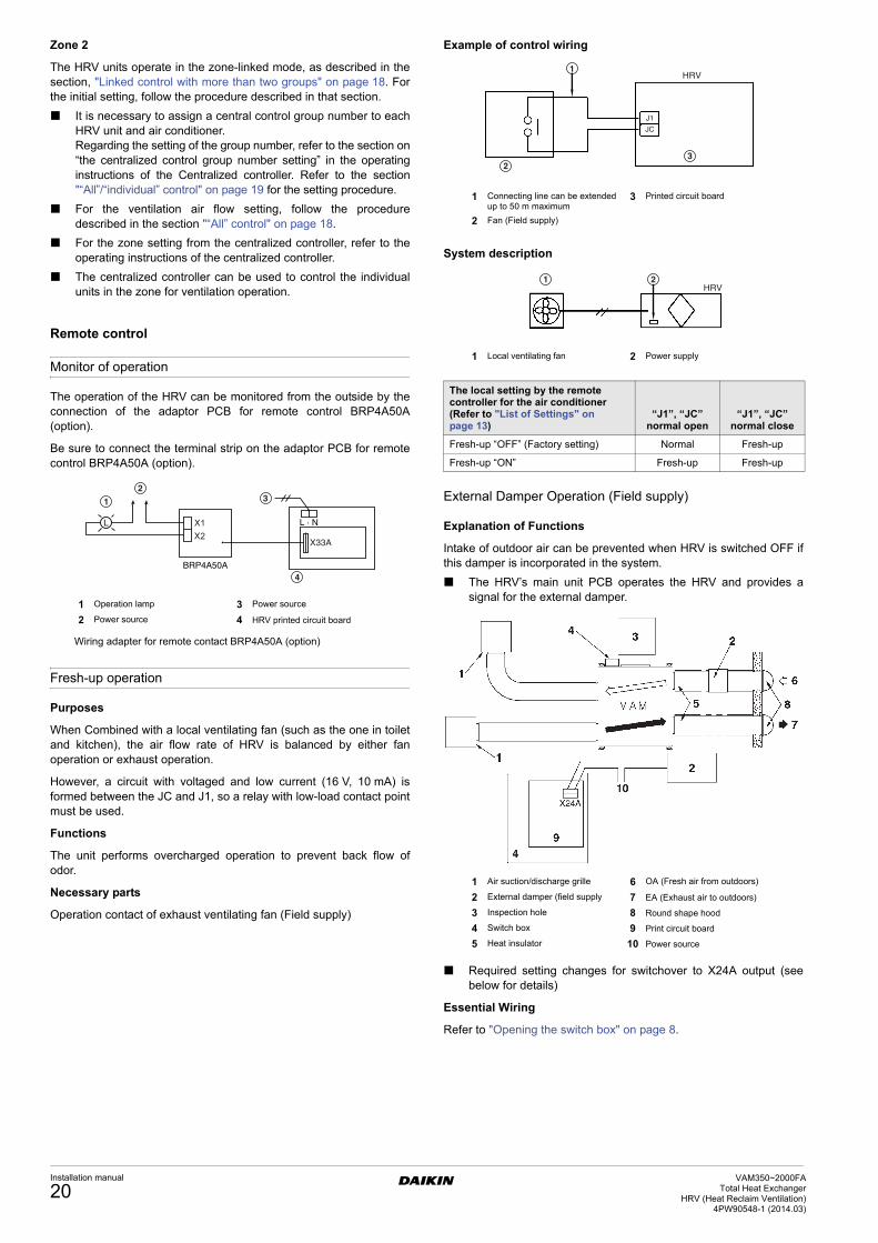
Fresh-up operation
Purposes
When Combined with a local ventilating fan (such as the one in toiletand kitchen), the air flow rate of HRV is balanced by either fanoperation or exhaust operation.
However, a circuit with voltaged and low current (16 V, 10 mA) isformed between the JC and J1, so a relay with low-load contact pointmust be used.
Functions
The unit performs overcharged operation to prevent back flow ofodor.
Necessary parts
Operation contact of exhaust ventilating fan (Field supply)
Example of control wiring
System description
External Damper Operation (Field supply)
Explanation of Functions
Intake of outdoor air can be prevented when HRV is switched OFF ifthis damper is incorporated in the system.
The HRV’s main unit PCB operates the HRV and provides asignal for the external damper.
Required setting changes for switchover to X24A output (seebelow for details)
Essential Wiring
Refer to "Opening the switch box" on page 8.
12
1 Operation lamp 3 Power source
2 Power source 4 HRV printed circuit board
Wiring adapter for remote contact BRP4A50A (option)
The local setting by the remote controller for the air conditioner (Refer to "List of Settings" on page 13)
“J1”, “JC” normal open
“J1”, “JC” normal close
Fresh-up “OFF” (Factory setting) Normal Fresh-up
Fresh-up “ON” Fresh-up Fresh-up
1
23
J1
JC
HRV
1 Connecting line can be extended up to 50 m maximum
3 Printed circuit board
2 Fan (Field supply)
1 2HRV
1 Local ventilating fan 2 Power supply
1 Air suction/discharge grille 6 OA (Fresh air from outdoors)
2 External damper (field supply 7 EA (Exhaust air to outdoors)
3 Inspection hole 8 Round shape hood
4 Switch box 9 Print circuit board
5 Heat insulator 10 Power source
Installation manual
20VAM350~2000FA
Total Heat ExchangerHRV (Heat Reclaim Ventilation)
4PW90548-1 (2014.03)
Nighttime free cooling operation
Automatic heat purge function at night
The nighttime free cooling is an energy-conserving function whichworks at night when the air conditioners is off, reducing the coolingload in the morning when the air conditioner is turned on. This ismainly for rooms that contain office equipment, which raises the roomtemperature.
Nighttime free cooling only works during cooling and whenconnected to Building Multi or VRV systems.
Nighttime free cooling is set to “off” in the factory settings; sorequest your dealer to turn it on if you intend to use it.
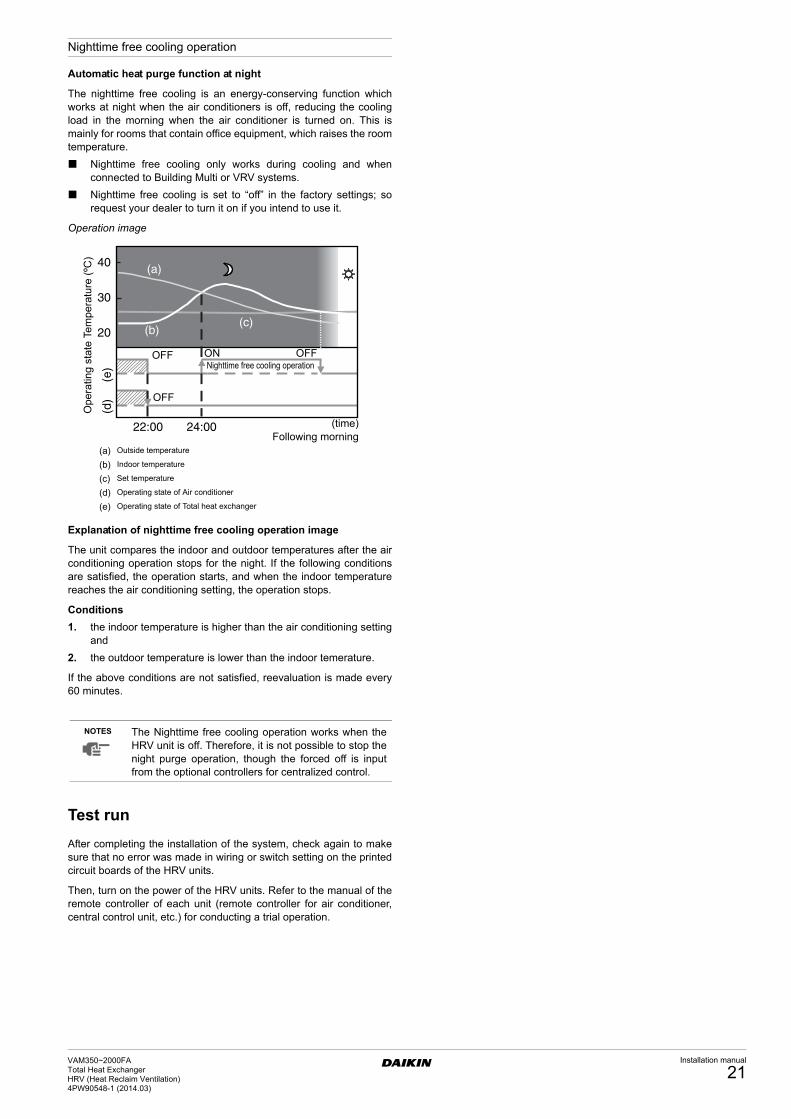
Operation image
Explanation of nighttime free cooling operation image
The unit compares the indoor and outdoor temperatures after the airconditioning operation stops for the night. If the following conditionsare satisfied, the operation starts, and when the indoor temperaturereaches the air conditioning setting, the operation stops.
Conditions
1. the indoor temperature is higher than the air conditioning settingand
2. the outdoor temperature is lower than the indoor temerature.
If the above conditions are not satisfied, reevaluation is made every60 minutes.
Test run
After completing the installation of the system, check again to makesure that no error was made in wiring or switch setting on the printedcircuit boards of the HRV units.
Then, turn on the power of the HRV units. Refer to the manual of theremote controller of each unit (remote controller for air conditioner,central control unit, etc.) for conducting a trial operation.
NOTES The Nighttime free cooling operation works when theHRV unit is off. Therefore, it is not possible to stop thenight purge operation, though the forced off is inputfrom the optional controllers for centralized control.
40
30
20
22:00 24:00
(d)
(e)
(a)
(b)(c)
(a) Outside temperature
(b) Indoor temperature
(c) Set temperature
(d) Operating state of Air conditioner
(e) Operating state of Total heat exchanger
Ope
ratin
g st
ate
Tem
pera
ture
(ºC
)
(time)Following morning
OFF
OFF
OFFONNighttime free cooling operation
VAM350~2000FATotal Heat ExchangerHRV (Heat Reclaim Ventilation) 4PW90548-1 (2014.03)
Installation manual
21
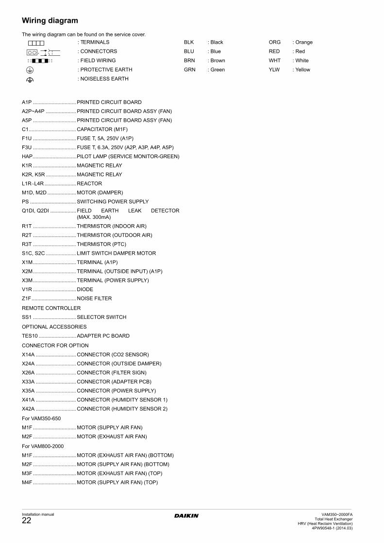
Wiring diagram
The wiring diagram can be found on the service cover.
A1P .............................. PRINTED CIRCUIT BOARD
A2P~A4P ..................... PRINTED CIRCUIT BOARD ASSY (FAN)
A5P .............................. PRINTED CIRCUIT BOARD ASSY (FAN)
C1................................. CAPACITATOR (M1F)
F1U .............................. FUSE T, 5A, 250V (A1P)
F3U .............................. FUSE T, 6.3A, 250V (A2P, A3P, A4P, A5P)
HAP...............................PILOT LAMP (SERVICE MONITOR-GREEN)
K1R .............................. MAGNETIC RELAY
K2R, K5R ..................... MAGNETIC RELAY
L1R∼L4R ...................... REACTOR
M1D, M2D .................... MOTOR (DAMPER)
PS ................................ SWITCHING POWER SUPPLY
Q1DI, Q2DI .................. FIELD EARTH LEAK DETECTOR(MAX. 300mA)
R1T .............................. THERMISTOR (INDOOR AIR)
R2T .............................. THERMISTOR (OUTDOOR AIR)
R3T .............................. THERMISTOR (PTC)
S1C, S2C ..................... LIMIT SWITCH DAMPER MOTOR
X1M.............................. TERMINAL (A1P)
X2M.............................. TERMINAL (OUTSIDE INPUT) (A1P)
X3M.............................. TERMINAL (POWER SUPPLY)
V1R .............................. DIODE
Z1F............................... NOISE FILTER
REMOTE CONTROLLER
SS1 .............................. SELECTOR SWITCH
OPTIONAL ACCESSORIES
TES10 .......................... ADAPTER PC BOARD
CONNECTOR FOR OPTION
X14A ............................ CONNECTOR (CO2 SENSOR)
X24A ............................ CONNECTOR (OUTSIDE DAMPER)
X26A ............................ CONNECTOR (FILTER SIGN)
X33A ............................ CONNECTOR (ADAPTER PCB)
X35A ............................ CONNECTOR (POWER SUPPLY)
X41A ............................ CONNECTOR (HUMIDITY SENSOR 1)
X42A ............................ CONNECTOR (HUMIDITY SENSOR 2)
For VAM350-650
M1F .............................. MOTOR (SUPPLY AIR FAN)
M2F .............................. MOTOR (EXHAUST AIR FAN)
For VAM800-2000
M1F .............................. MOTOR (EXHAUST AIR FAN) (BOTTOM)
M2F .............................. MOTOR (SUPPLY AIR FAN) (BOTTOM)
M3F .............................. MOTOR (EXHAUST AIR FAN) (TOP)
M4F .............................. MOTOR (SUPPLY AIR FAN) (TOP)
: TERMINALS BLK : Black ORG : Orange
: CONNECTORS BLU : Blue RED : Red
: FIELD WIRING BRN : Brown WHT : White
: PROTECTIVE EARTH GRN : Green YLW : Yellow
: NOISELESS EARTH
Installation manual
22VAM350~2000FA
Total Heat ExchangerHRV (Heat Reclaim Ventilation)
4PW90548-1 (2014.03)

3PW90202-2 2014.03
DAIKIN ISITMA VE SOĞUTMA SİSTEMLERİ SANAYİ TİCARET A.Ş.Hürriyet Mahallesi Yakacık D-100 Kuzey Yanyol No:49/1 D:2 Kartal / İstanbul, TÜRKİYETel : 0216 453 27 00 / Faks : 0216 671 06 00Call Center: 444 999 0www.daikin.com.tr
DAIKIN TURKEY
Cop
yrig
ht 2
014
Dai
kin