Embed Size (px)
Citation preview
INSTALLATION MANUALNETWORK CONVERTOR
For authorized service personnel only.
INSTALLATIONSANLEITUNGNETZWERKKONVERTER
Nur für autorisiertes Fachpersonal.
MANUEL D’INSTALLATIONADAPTATEUR RESEAU
Pour le personnel agréé uniquement.
MANUAL DE INSTALACIÓNCONVERTIDOR DE RED
Únicamente para personal de servicio autorizado.
MANUALE DI INSTALLAZIONECONVERTITORE DI RETE
A uso esclusivo del personale tecnico autorizzato.
ΕΓΧΕΙΡΙΔΙΟ ΕΓΚΑΤΑΣΤΑΣΗΣΜΕΤΑΤΡΟΠΕΑΣ ΔΙΚΤΥΟΥ
Μόνο για εξουσιοδοτημένο τεχνικό προσωπικό.
MANUAL DE INSTALAçãOCONVERSOR DE REDE
Apenas para técnicos autorizados.
РУКОВОДСТВО ПО УСТАНОВКЕСЕТЕВОЙ КОНВЕРТОР
Только для авторизованного обслуживающего персонала.
MONTAJ KILAVUZUAÐ DÖNÜÞTÜRÜCÜ
Yalnızca yetkili servis personeli için.
安装说明书网络转换器
仅针对授权的专业维修人员。
Engl
ish
Deu
tsch
Fran
çais
Espa
ñol
Italia
noEλ
ληvI
kάPo
rtug
uês
Русс
кий
Türk
çe中 文
PART NO. 9374707102
UTY-VGGXZ1
En-1
SAFETY PRECAUTIONS11 The “SAFETY PRECAUTIONS” indicated in ▪ this manual contain important information pertaining to your safety. Be sure to observe them.Request the user to keep ▪ this manual on hand for future use, such as for relocating or repairing the unit.
WARNINGThis mark indicates procedures which, if im-properly performed, might lead to the death or serious injury of the user.
Perform electrical work by an authorized service personnel in ac-cordance with this manual and the electrical wiring regulations or implementation regulations of the country. Also do not install this unit by yourself. Improper electric work will cause electric shock or a fire.
Perform installation work in accordance with this manual. Request an authorized service personnel to perform installation work. Do not install this unit by yourself. Improper installation will cause injury, electric shock, fire, etc.
In the event of a malfunction (burning smell, etc.), immediately stop op-eration, turn off the electrical breaker, and consult authorized service personnel.
Install a leakage circuit breaker to power supply cable in accordance with the related laws and regulations and electric company standards.
Use a power source exclusively for this unit. Never share the power source with other electrical equipment. Doing so will cause fire and electric shock.
Do not install the unit in the following areas:Do not install the unit near a source of heat, steam, or flammable gas. ▪Area filled with mineral oil or containing a large amount of splashed ▪oil or steam, such as a kitchen. It will deteriorate plastic parts, caus-ing the parts to fail or the unit to leak water.Area that generates substances that adversely affect the equipment, ▪such as sulfuric gas, chlorine gas, acid, or alkali. It will cause the copper pipes and brazed joints to corrode, which can cause refriger-ant leakage.
Area containing equipment that generates electromagnetic interfer- ▪ence. It will cause the control system to malfunction, preventing the unit from operating normally.Area that can cause combustible gas to leak, contains suspended carbon fibers or flammable dust, or volatile inflammables such as paint thinner or gasoline. If gas leaks and settles around the unit, it can cause a fire.Do not use the unit for special purposes, such as storing food, rais- ▪ing animals, growing plants, or preserving precision devices or art objects. It can degrade the quality of the preserved or stored objects.Install the unit in a well-ventilated place avoiding rains and direct sun- ▪light.
Do not operate this unit when your hands are wet. Touching the unit with wet hands will cause an electric shock.
If children may approach the unit, take preventive measures so that they cannot reach the unit.
CAUTIONThis mark indicates procedures which, if improp-erly performed, might possibly result in personal harm to the user or damage to property.
Pay abundant care when transporting this unit because it is a precision device. Improper transportation will cause trouble.
Do not touch the switches with sharp objects. Doing so will cause injury, trouble, or electric shock.
Do not expose this unit directly to water. Doing so will cause trouble, electric shock, or heating.
Do not set vessels containing a liquid on this unit. Doing so will cause heating, fire, or electric shock.
Dispose of the packing materials safely. Tear and dispose of the plastic packing bags so that children cannot play with them. There is the dan-ger of suffocation if children play with the original plastic bags.
Do not insert articles into the slit parts of this unit. Doing so will cause trouble, heating, or electric shock.
MAIN UNIT AND ACCESSORIES21 The following installation parts are supplied. Use them as required.
Name and Shape Q’ty Application
Network convertor
1
Main unit
Installation manual
1
This manual
Cable tie
4
For mounting the power supply cable, remote controller cable and transmission cable.
Screw (M4 x 20 mm)
4
For mounting the network conver-tor.
Dust proof bushing
1For connecting the power supply cable. (Except in U.S.A. and Canada)
INSTALLATION MANUALPART NO. 9374707102NETWORK CONVERTOR
CONTENTS1. SAFETY PRECAUTIONS ……………………………………………… 12. MAIN UNIT AND ACCESSORIES …………………………………… 13. ELECTRICAL REQUIREMENT ……………………………………… 24. SELECTING AN INSTALLATION LOCATION ……………………… 2
4. 1. Dimensions …………………………………………………… 25. WIRING…………………………………………………………………… 2
5. 1. Wiring method ………………………………………………… 26. INSTALLING THE NETWORK CONVERTOR ……………………… 4
6. 1. Connecting the power supply cable ………………………… 46. 2. Connecting the transmission cables ……………………… 5
7. USING THE NETWORK CONVERTOR …………………………… 5
SETTING METHOD WHEN CONNECTING A GROUP REMOTE ■CONTROLLER
8. CIRCUIT BOARD SETTING ………………………………………… 59. TURNING ON THE POWER ………………………………………… 610. ERROR CODE ………………………………………………………… 6
SETTING METHOD WHEN CONNECTING A SINGLE SPLIT TYPE ■INDOOR UNIT
11. CONNECTION OF REMOTE CONTROLLER CABLE …………… 612. CIRCUIT BOARD SETTING ………………………………………… 713. TURNING ON THE POWER ………………………………………… 814. SETTING CHECK MODE ……………………………………………… 815. ERROR CODE ………………………………………………………… 8
En-2
WIRING51
WARNINGBefore starting installation work, turn off the power of this unit and the connection destination. Do not turn on the power again until installa-tion is completed. Otherwise, it will cause electric shock or fire.
Use the accessories or specified power supply cable and transmission cables. Do not modify power supply cable and transmission cables other than those specified, do not use extension cables, and do not use independent branch wiring. Overcurrent may cause electric shock or fire.
Install the transmission cables securely to the terminal block. Confirm that external force is not applied to the cable. Use transmission cables made of the specified cable. If intermediate connection or insertion fixing are imperfect, it will cause electric shock, fire, etc.
When connecting the power supply cable and transmission cable, route the cables so that the cover of this unit is securely fixed. If the cover is imperfectly fixed, it may cause fire or overheating of the termi-nals.
Perform earth (ground) work positively. Do not connect the earth (ground) cable to a telephone cable, water pipe, or conductor rod.
Always fasten the outside covering of the transmission cables with the cable clamp. (If the insulator is chafed, electric leakage may occur.)
Perform all wiring works so that the user does not touch the wiring. Do-ing so will cause injury or electric shock.
If any cable is damaged, do not repair or modify it yourself. Improper work will cause electric shock or fire.
CAUTIONDo not bind the remote controller cable and the transmission cable together with or parallel to the power supply cable of the indoor and outdoor units. It may cause erroneous operation.
When performing wiring work, be careful not to damage the cable or injure yourself. Also, connect the connectors securely. Loose connec-tors will cause trouble, heating, fire, or electric shock.
Install the indoor and outdoor units, power supply cable, transmission cable and remote controller cable 1 m (40 in.) away from television and radio to avoid distorted images and noise. Otherwise, a malfunction could result.
Perform wiring so that water does not enter this unit along the external wiring. Always install a trap to the wiring or take other countermea-sures. Otherwise it will cause trouble or electric shock or fire.
Confirm the name of each unit and name of each terminal block of the unit and connect the wiring in accordance with the directions given in the manual so that there is no incorrect wiring. Incorrect wiring will damage the electric parts and cause smoke and fire.
When installing the transmission cables near a source of electromag-netic waves, use shielded cable. Otherwise, a breakdown or malfunction could result.
The terminal screws and earth (ground) screws have different shapes. Be sure to install the screws in the correct locations. If the screws are installed in the wrong locations, the circuit board could be damaged.
Wiring method51 11 Setting method when connecting a group remote 51 11 11 controller
Number of connected network convertorsUp to a total of 16 network convertors (UTY- ▪ VGGXZ1) and touch panel controllers, etc. can be connected in the VRF system.Up to 4 group remote controllers can be connected to1 network con- ▪vertor (UTY-VGGXZ1).Total remote controller cable length when connected to 1 converter ▪ 100 m (328 ft.)
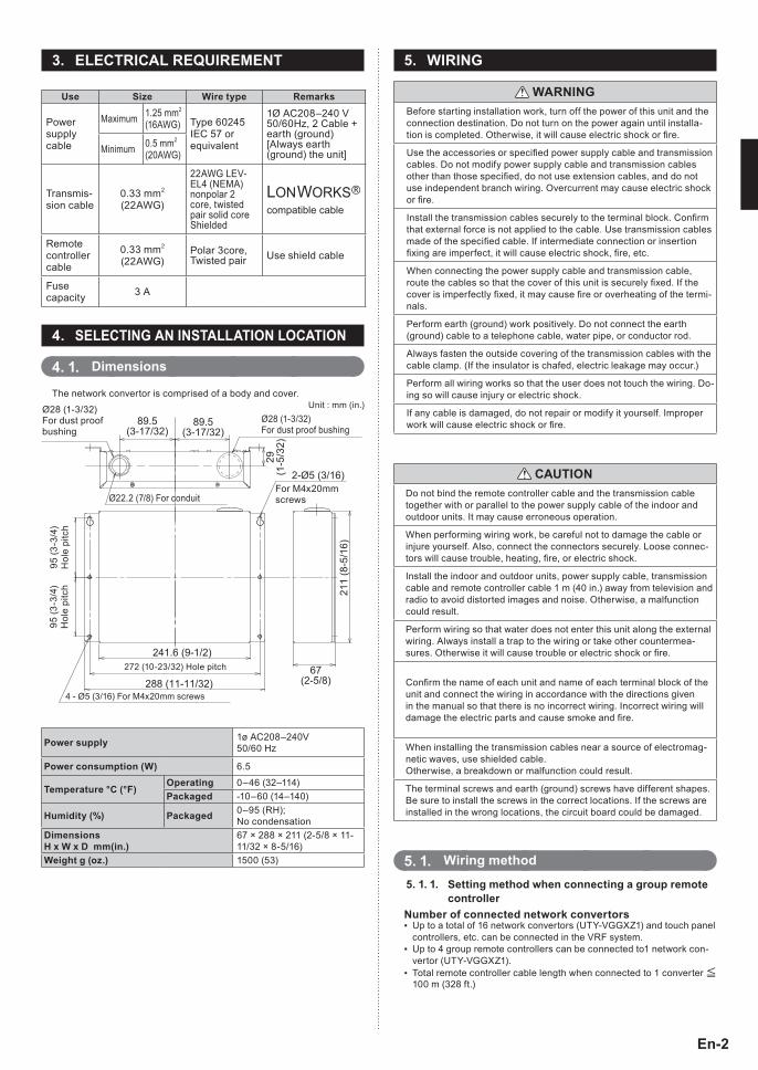
ELECTRICAL REQUIREMENT31
Use Size Wire type Remarks
Power supply cable
Maximum 1.25 mm2
(16AWG) Type 60245 IEC 57 or equivalent
1Ø AC208–240 V 50/60Hz, 2 Cable + earth (ground) [Always earth (ground) the unit]Minimum 0.5 mm2
(20AWG)
Transmis-sion cable
0.33 mm2
(22AWG)
22AWG LEV-EL4 (NEMA) nonpolar 2 core, twisted pair solid core Shielded
LONWORKS compatible cable
Remote controller cable
0.33 mm2
(22AWG)Polar 3core, Twisted pair Use shield cable
Fuse capacity 3 A
SELECTING AN INSTALLATION LOCATION41
Dimensions41 11 The network convertor is comprised of a body and cover.
211
(8-5
/16)
241.6 (9-1/2)
288 (11-11/32)
2-Ø5 (3/16)
67(2-5/8)
89.5(3-17/32)
89.5(3-17/32)
29(1
-5/3
2)
Ø28 (1-3/32)For dust proof bushing
4 - Ø5 (3/16) For M4x20mm screws
Ø28 (1-3/32) For dust proof bushing
For M4x20mmscrews
272 (10-23/32) Hole pitch
95 (3
-3/4
)H
ole
pitc
h95
(3-3
/4)
Hol
e pi
tch
Unit : mm (in.)
Ø22.2 (7/8) For conduit
Power supply 1ø AC208–240V 50/60 Hz
Power consumption (W) 6.5
Temperature °C (°F)Operating 0–46 (32–114)Packaged -10–60 (14–140)
Humidity (%) Packaged 0–95 (RH); No condensation
Dimensions H x W x D mm(in1)
67 × 288 × 211 (2-5/8 × 11-11/32 × 8-5/16)
Weight g (oz1) 1500 (53)
En-3
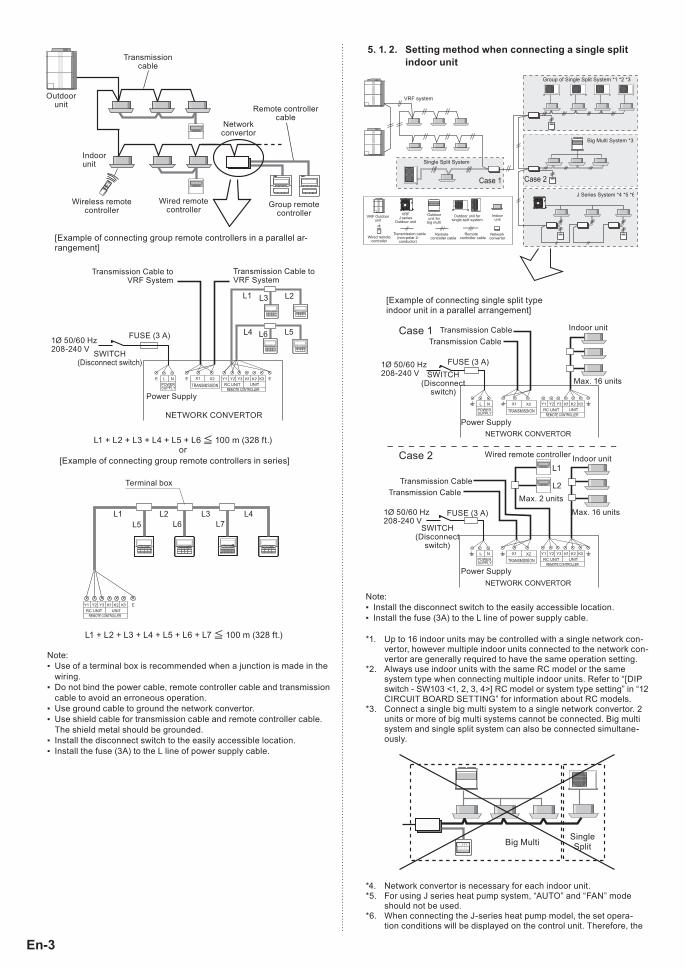
Setting method when connecting a single split 51 11 21 indoor unit
K K KRC UNIT UNITPOWER
SUPPLY
K K KRC UNIT UNITPOWER
SUPPLY
Power Supply
FUSE (3 A)
SWITCH (Disconnect
switch)
Power Supply
NETWORK CONVERTOR
NETWORK CONVERTOR
SWITCH (Disconnect
switch)
FUSE (3 A)
Indoor unit
Indoor unitWired remote controller
Max. 16 units
Max. 16 units
Max. 2 units
Transmission Cable
Transmission Cable
Transmission Cable
Transmission Cable
[Example of connecting single split type indoor unit in a parallel arrangement]
Case 2
Case 1
1Ø 50/60 Hz208-240 V
1Ø 50/60 Hz208-240 V
Note:Install the disconnect switch to the easily accessible location. ▪Install the fuse (3A) to the L line of power supply cable. ▪
Up to 16 indoor units may be controlled with a single network con-*1. vertor, however multiple indoor units connected to the network con-vertor are generally required to have the same operation setting.Always use indoor units with the same RC model or the same *2. system type when connecting multiple indoor units. Refer to “[DIP switch - SW103 <1, 2, 3, 4>] RC model or system type setting” in “12 CIRCUIT BOARD SETTING” for information about RC models.Connect a single big multi system to a single network convertor. 2 *3. units or more of big multi systems cannot be connected. Big multi system and single split system can also be connected simultane-ously.
Big Multi SingleSplit
Network convertor is necessary for each indoor unit.*4. For using J series heat pump system, “AUTO” and “FAN” mode *5. should not be used.When connecting the J-series heat pump model, the set opera-*6. tion conditions will be displayed on the control unit. Therefore, the
Transmissioncable
Indoorunit
Wireless remotecontroller
Wired remotecontroller Group remote
controller
Remote controllercable
Networkconvertor
Outdoorunit
K K KRC UNIT UNITPOWER
SUPPLY
[Example of connecting group remote controllers in a parallel ar-rangement]
L1 + L2 + L3 + L4 + L5 + L6 100 m (328 ft.)or
1Ø 50/60 Hz208-240 V
Transmission Cable to VRF System
FUSE (3 A)
SWITCH (Disconnect switch)
Power Supply
Transmission Cable to VRF System
NETWORK CONVERTOR
K K KRC UNIT UNIT
Terminal box
[Example of connecting group remote controllers in series]
L1 + L2 + L3 + L4 + L5 + L6 + L7 100 m (328 ft.)
Note:Use of a terminal box is recommended when a junction is made in the ▪wiring.Do not bind the power cable, remote controller cable and transmission ▪cable to avoid an erroneous operation.Use ground cable to ground the network convertor. ▪Use shield cable for transmission cable and remote controller cable. ▪The shield metal should be grounded.Install the disconnect switch to the easily accessible location. ▪Install the fuse (3A) to the L line of power supply cable. ▪
En-4
indoor unit may enter the operation standby condition as described below.
Ex. 1) If FAN setting is selected from the control unit, the LED on the indoor unit will flash and the unit will enter the operation standby condition. Select another operation mode to clear the standby condition.
Ex. 2) If an operation mode that is different from a currently operating indoor unit is selected from the control unit, the LED on the in-door unit will flash and the unit will enter the operation standby condition. Select the operation mode of the currently operat-ing indoor unit to clear the standby condition. Or, if operation becomes possible, such as by stopping the other indoor unit, the standby condition will be cleared and the indoor unit will automatically start operating with the selected mode.
Number of connected network convertorsUp to 100 network convertors may be connected in the VRF system. ▪
A single network convertor is considered as a single refrigerant *system, irrespective of the number of connected single split type.
Compatible indoor unitsJ-series �
Wireless RC model ÍBig multi Simultaneous model �
Individual model �Single split type �
Wired RC model �
Wireless RC model ÍWindow type Í
Connectable types of indoor unit and remote controllerConnectable remote controllers z3 types of wired remote controller shown in the table below can be connected to this unit.
Model name RC number
UTB-*UB AR-3TA**UTB-*UD AR-6TC**
UTY-RNN** AR-WAE**(* arbitrary character)
YYYYYYYY
Model name
RC number
Rear View
Connectable indoor units zIndoor units that accept following wired remote controllers (accesso-ries or optional parts) are connectable with this unit.
RC number AR-3TA**, AR-6TC** , AR-WAE**EZ-099DHSE-R, EZ-000DHSE-R, EZ-0001HSE-R,EZ-000GHSE-R, EZ-00004HSE-R, EZ-00005HSE-R,EZ-0015HSE-R, EZ-0019HSE-R, EZ-099DHSEFR,EZ-0001HSEFR, EZ-000DHSEFR, EZ-000GHSEFR,EZ-0015HSEFR
EZ-0994HSE-R, EZ-000EHSE-R, EZ-0994HSEFREZ-099CWSE-R, EZ-000AWSE-R, EZ-0001WSE-R,
EZ-000FWSE-R, EZ-0012WSE-R, EZ-099CWSEFR,EZ-0001WSEFR, EZ-000AWSEFR
EZ-09906WSE-R, EZ-000BWSE-R, EZ-09906WSEFR
EZ type remote controllers cannot control indoor units via this unit. When you want to operate indoor units directly by remote controller, the optional remote controller must be purchased.
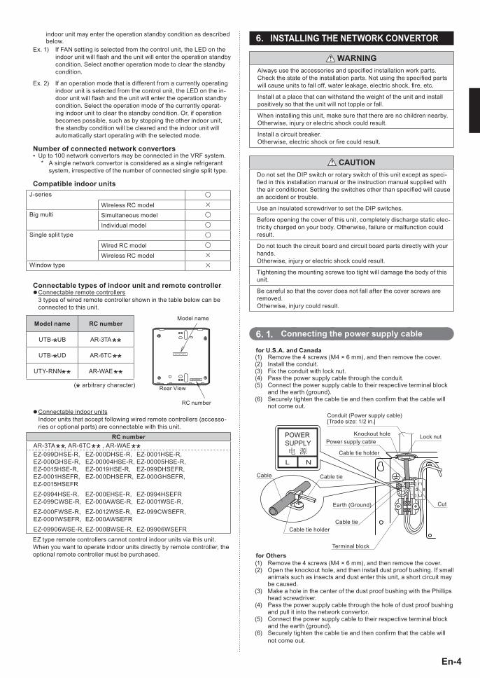
INSTALLING THE NETWORK CONVERTOR61
WARNINGAlways use the accessories and specified installation work parts. Check the state of the installation parts. Not using the specified parts will cause units to fall off, water leakage, electric shock, fire, etc.
Install at a place that can withstand the weight of the unit and install positively so that the unit will not topple or fall.
When installing this unit, make sure that there are no children nearby. Otherwise, injury or electric shock could result.
Install a circuit breaker. Otherwise, electric shock or fire could result.
CAUTIONDo not set the DIP switch or rotary switch of this unit except as speci-fied in this installation manual or the instruction manual supplied with the air conditioner. Setting the switches other than specified will cause an accident or trouble.
Use an insulated screwdriver to set the DIP switches.
Before opening the cover of this unit, completely discharge static elec-tricity charged on your body. Otherwise, failure or malfunction could result.
Do not touch the circuit board and circuit board parts directly with your hands. Otherwise, injury or electric shock could result.
Tightening the mounting screws too tight will damage the body of this unit.
Be careful so that the cover does not fall after the cover screws are removed. Otherwise, injury could result.
Connecting the power supply cable61 11 for U1S1A1 and Canada
Remove the 4 screws (M4 × 6 mm), and then remove the cover.(1) Install the conduit.(2) Fix the conduit with lock nut.(3) Pass the power supply cable through the conduit.(4) Connect the power supply cable to their respective terminal block (5) and the earth (ground).Securely tighten the c(6) able tie and then confirm that the cable will not come out.
Conduit (Power supply cable)[Trade size: 1/2 in.]
Knockout holePower supply cable
Cable tie holder
Earth (Ground)
Cable
Cable tie holder
Cable tie
Lock nut
Cut
Cable tie
Terminal block
for OthersRemove the 4 screws (M4 × 6 mm), and then remove the(1) cover.Open the knockout hole, and then install dust proof bushing. If small (2) animals such as insects and dust enter this unit, a short circuit may be caused.Make a hole in the center of the dust proof bushing with the Phillips (3) head screwdriver.Pass the power supply cable through the hole of dust proof bushing (4) and pull it into the network convertor.Connect the power supply cable to their respective terminal block (5) and the earth (ground).Securely tighten the c(6) able tie and then confirm that the cable will not come out.
En-5
Dust proof bushing
Knockout hole
Power supply cable
Cable tie holder
Earth (Ground)
Cable tie
Cable tie
Cut
Cable
Tightening torque for installing cables to terminal block0.8 to 1.2 N • m (7.1 to 10.6 lbf∙in)
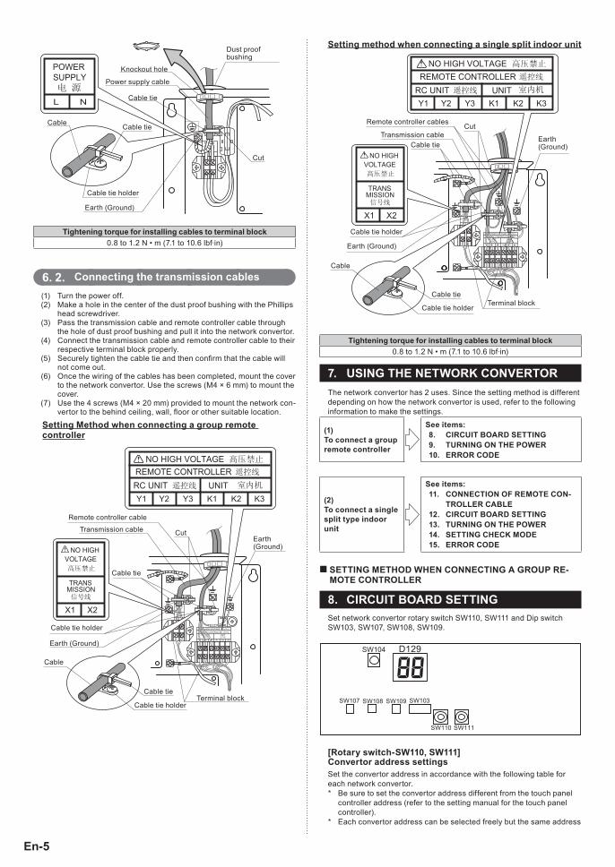
Connecting the transmission cables61 21 Turn the power off.(1) Make a hole in the center of the dust proof bushing with the Phillips (2) head screwdriver.Pass the transmission (3) cable and remote controller cable through the hole of dust proof bushing and pull it into the network convertor.Connect the transmission cable(4) and remote controller cable to their respective terminal block properly.Securely tighten the (5) cable tie and then confirm that the cable will not come out.Once the wiring of the cables has been completed, mount the cover (6) to the network convertor. Use the screws (M4 × 6 mm) to mount the cover.Use the 4 screws (M4 × 20 mm) provided to mount the network con-(7) vertor to the behind ceiling, wall, floor or other suitable location.
Setting Method when connecting a group remote controller
Remote controller cable
Transmission cable
Cable tie
Cable tie
Earth (Ground)
Earth (Ground)
Cable tie holder
Cable tie holderTerminal block
Cable
Cut
Setting method when connecting a single split indoor unit
Remote controller cables
Transmission cableCable tie
Cable tie
Earth (Ground)
Cable tie holder
Cable tie holderTerminal block
Cable
Earth (Ground)
Cut
Tightening torque for installing cables to terminal block0.8 to 1.2 N • m (7.1 to 10.6 lbf∙in)
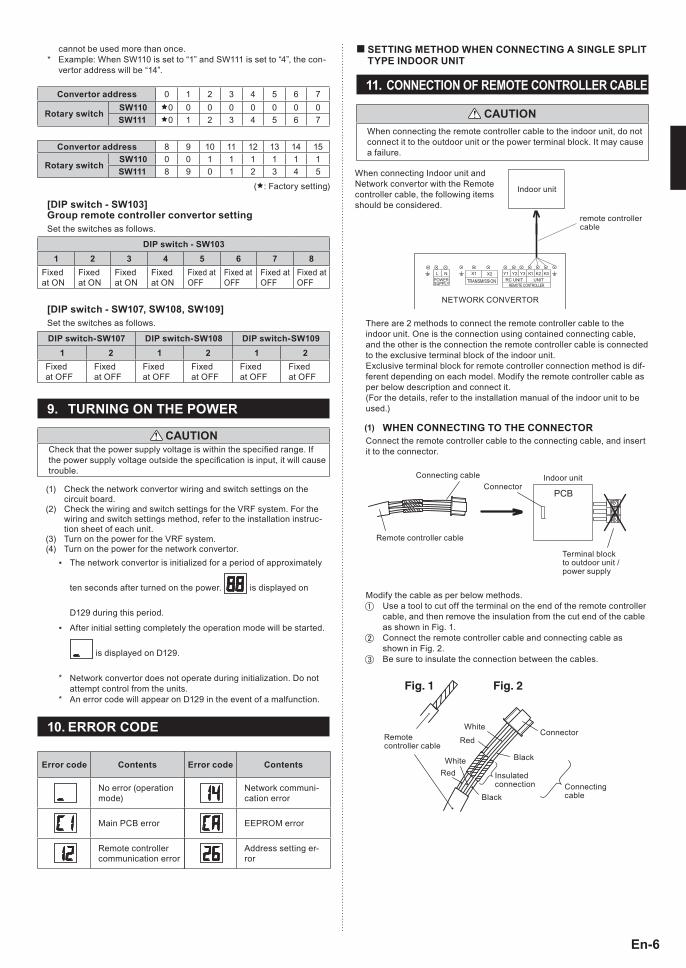
USING THE NETWORK CONVERTOR71 The network convertor has 2 uses. Since the setting method is different depending on how the network convertor is used, refer to the following information to make the settings.
(1) To connect a group remote controller
See items:81 CIRCUIT BOARD SETTING91 TURNING ON THE POWER101 ERROR CODE
(2) To connect a single split type indoor unit
See items:111 CONNECTION OF REMOTE CON-
TROLLER CABLE121 CIRCUIT BOARD SETTING131 TURNING ON THE POWER141 SETTING CHECK MODE151 ERROR CODE
SETTING METHOD WHEN CONNECTING A GROUP RE-��MOTE CONTROLLER
CIRCUIT BOARD SETTING81 Set network convertor rotary switch SW110, SW111 and Dip switch SW103, SW107, SW108, SW109.
[Rotary switch-SW110, SW111] Convertor address settingsSet the convertor address in accordance with the following table for each network convertor.
Be sure to set the convertor address different from the touch panel *controller address (refer to the setting manual for the touch panel controller).Each convertor address can be selected freely but the same address *
En-6
cannot be used more than once.Example: When SW110 is set to “1” and SW111 is set to “4”, the con- *vertor address will be “14”.
Convertor address 0 1 2 3 4 5 6 7
Rotary switchSW110 0 0 0 0 0 0 0 0SW111 0 1 2 3 4 5 6 7
Convertor address 8 9 10 11 12 13 14 15
Rotary switchSW110 0 0 1 1 1 1 1 1SW111 8 9 0 1 2 3 4 5
(: Factory setting)
[DIP switch - SW103] Group remote controller convertor settingSet the switches as follows.
DIP switch - SW1031 2 3 4 5 6 7 8
Fixed at ON
Fixed at ON
Fixed at ON
Fixed at ON
Fixed at OFF
Fixed at OFF
Fixed at OFF
Fixed at OFF
[DIP switch - SW107, SW108, SW109]Set the switches as follows.
DIP switch-SW107 DIP switch-SW108 DIP switch-SW1091 2 1 2 1 2
Fixed at OFF
Fixed at OFF
Fixed at OFF
Fixed at OFF
Fixed at OFF
Fixed at OFF
TURNING ON THE POWER91
CAUTIONCheck that the power supply voltage is within the specified range. If the power supply voltage outside the specification is input, it will cause trouble.
Check the network convertor wiring and switch settings on the (1) circuit board.Check the wiring and switch settings for the VRF system. For the (2) wiring and switch settings method, refer to the installation instruc-tion sheet of each unit.Turn on the power for the VRF system.(3) Turn on the power for the network convertor.(4)
The network convertor is initialized for a period of ▪ approximately
ten seconds after turned on the power. is displayed on
D129 during this period.
After initial setting completely the operation mode will ▪ be started.
is displayed on D129.
Network convertor does not operate during initialization. Do not *attempt control from the units.An error code will appear on D129 in the event of a malfunction. *
ERROR CODE101
Error code Contents
No error (operation mode)
Main PCB error
Remote controller communication error
Error code Contents
Network communi-cation error
EEPROM error
Address setting er-ror
SETTING METHOD WHEN CONNECTING A SINGLE SPLIT ��TYPE INDOOR UNIT
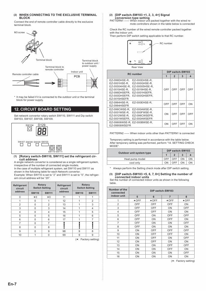
CONNECTION OF REMOTE CONTROLLER CABLE111
CAUTIONWhen connecting the remote controller cable to the indoor unit, do not connect it to the outdoor unit or the power terminal block. It may cause a failure.
K K KRC UNIT UNITPOWER
SUPPLY
Indoor unit
NETWORK CONVERTOR
remote controller cable
When connecting Indoor unit and Network convertor with the Remote controller cable, the following items should be considered.
There are 2 methods to connect the remote controller cable to the indoor unit. One is the connection using contained connecting cable, and the other is the connection the remote controller cable is connected to the exclusive terminal block of the indoor unit.Exclusive terminal block for remote controller connection method is dif-ferent depending on each model. Modify the remote controller cable as per below description and connect it.(For the details, refer to the installation manual of the indoor unit to be used.)
WHEN CONNECTING TO THE CONNECTOR(1) Connect the remote controller cable to the connecting cable, and insert it to the connector.
PCB
Connecting cableConnector
Terminal block to outdoor unit / power supply
Remote controller cable
Indoor unit
Modify the cable as per below methods.Use a tool to cut off the terminal on the end of the remote controller �cable, and then remove the insulation from the cut end of the cable as shown in Fig. 1.Connect the remote controller cable and connecting cable as �shown in Fig. 2.Be sure to insulate the connection between the cables. �
Fig. 1 Fig. 2
Remote controller cable
WhiteRed
Red
WhiteConnector
Black
Black
Insulated connection Connecting
cable
En-7
WHEN CONNECTING TO THE EXCLUSIVE TERMINAL (2) BLOCK
Connect the end of remote controller cable directly to the exclusive terminal block.
PCBRemote controller cable
Terminal block to remote controller
Indoor unit
M3 screw
Terminal block to outdoor unit / power supply
Terminal block
It may be failed if it is connected to the outdoor unit or the terminal *block for power supply.
CIRCUIT BOARD SETTING121 Set network convertor rotary switch SW110, SW111 and Dip switch SW103, SW107, SW108, SW109.
[Rotary switch-SW110, SW111] set the refrigerant cir-(1) cuit address
A single network convertor is considered as a single refrigerant system, irrespective of the number of connected single models.In the case of multiple refrigerant system, set SW110 and SW111 as shown in the following table for each Network convertor.Example: When SW110 is set to “2” and SW111 is set to “0”, the refriger-ant circuit address will be “20”.
Refrigerantcircuit
address
Rotary Switch Setting
Refrigerantcircuit
address
Rotary Switch Setting
SW110 SW111 SW110 SW1110 0 0 11 1 11 0 1 12 1 22 0 2 13 1 33 0 3 14 1 44 0 4 15 1 55 0 5 16 1 66 0 6 17 1 77 0 78 0 89 0 9 98 9 810 1 0 99 9 9
(: Factory setting)
[DIP switch-SW103 <1, 2, 3, 4>] Signal(2) conversion type setting
PATTERN1 —— When indoor unit packed together with the wired re-mote controllers shown in the table below is connected
Check the RC number of the wired remote controller packed together with the indoor unit.Then perform DIP switch setting applicable to that RC number.
RC number
Rear View
RC number DIP switch-SW103
1 2 3 4 EZ-099DHSE-R, EZ-000DHSE-R,EZ-0001HSE-R, EZ-000GHSE-R,EZ-00004HSE-R, EZ-00005HSE-R,EZ-0015HSE-R, EZ-0019HSE-R,EZ-099DHSEFR, EZ-0001HSEFR,EZ-000DHSEFR, EZ-000GHSEFR,EZ-0015HSEFR
OFF OFF OFF OFF
EZ-0994HSE-R, EZ-000EHSE-R,EZ-0994HSEFR OFF OFF OFF ON
EZ-099CWSE-R, EZ-000AWSE-R,EZ-0001WSE-R, EZ-000FWSE-R,EZ-0012WSE-R, EZ-099CWSEFR,EZ-0001WSEFR, EZ-000AWSEFR
ON OFF OFF OFF
EZ-09906WSE-R, EZ-000BWSE-R,EZ-09906WSEFR ON OFF OFF ON
PATTERN2 —— When indoor units other than PATTERN1 is connected
Temporary setting is performed in accordance with the table below. After temporary setting was performed, perform “14. SETTING CHECK MODE”.
Outdoor unit system typeDIP switch-SW103
1 2 3 4 Heat pump model OFF OFF ON ON
cool only ON OFF ON ON
Always perform the Setting check mode after DIP switch setting. *
[DIP switch-SW103 <5, 6, 7, 8>] Setting the number of (3) connected indoor units
Set the number of connected indoor units as shown in the following table.
Number of the connected indoor unit
DIP switch-SW103
5 6 7 81 OFF OFF OFF OFF 2 OFF OFF OFF ON 3 OFF OFF ON OFF 4 OFF OFF ON ON 5 OFF ON OFF OFF 6 OFF ON OFF ON 7 OFF ON ON OFF 8 OFF ON ON ON 9 ON OFF OFF OFF 10 ON OFF OFF ON 11 ON OFF ON OFF 12 ON OFF ON ON 13 ON ON OFF OFF 14 ON ON OFF ON 15 ON ON ON OFF 16 ON ON ON ON
(: Factory setting)
En-8
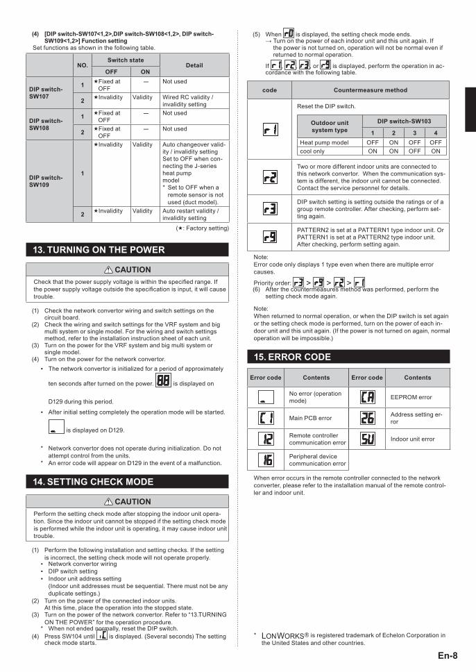
When (5) is displayed, the setting check mode ends. → Turn on the power of each indoor unit and this unit again. If
the power is not turned on, operation will not be normal even if returned to normal operation.
If , , , or is displayed, perform the operation in ac-cordance with the following table.
code Countermeasure method
Reset the DIP switch.
Outdoor unit system type
DIP switch-SW103
1 2 3 4Heat pump model OFF ON OFF OFFcool only ON ON OFF ON
Two or more different indoor units are connected to this network convertor. When the communication sys-tem is different, the indoor unit cannot be connected. Contact the service personnel for details.
DIP switch setting is setting outside the ratings or of a group remote controller. After checking, perform set-ting again.
PATTERN2 is set at a PATTERN1 type indoor unit. Or PATTERN1 is set at a PATTERN2 type indoor unit. After checking, perform setting again.
Note:Error code only displays 1 type even when there are multiple error causes.
Priority order: > > > After the countermeasures method was performed, perform the (6) setting check mode again.
Note:When returned to normal operation, or when the DIP switch is set again or the setting check mode is performed, turn on the power of each in-door unit and this unit again. (If the power is not turned on again, normal operation will be impossible.)
ERROR CODE151
Error code Contents
No error (operation mode)
Main PCB error
Remote controller communication error
Peripheral device communication error
Error code Contents
EEPROM error
Address setting er-ror
Indoor unit error
When error occurs in the remote controller connected to the network converter, please refer to the installation manual of the remote control-ler and indoor unit.
[DIP switch-SW107<1,2>,DIP switch-SW108<1,2>, DIP switch-(4) SW109<1,2>] Function setting
Set functions as shown in the following table.
NO1Switch state
DetailOFF ON
DIP switch-SW107
1 Fixed at OFF
- Not used
2 Invalidity Validity Wired RC validity / invalidity setting
DIP switch-SW108
1 Fixed at OFF
- Not used
2 Fixed at OFF
- Not used
DIP switch-SW109
1
Invalidity Validity Auto changeover valid-ity / invalidity settingSet to OFF when con-necting the J-series heat pump model
Set to OFF when a *remote sensor is not used (duct model).
2 Invalidity Validity Auto restart validity / invalidity setting
(: Factory setting)
TURNING ON THE POWER131
CAUTIONCheck that the power supply voltage is within the specified range. If the power supply voltage outside the specification is input, it will cause trouble.
Check the network convertor wiring and switch settings on the (1) circuit board.Check the wiring and switch settings for the VRF system and big (2) multi system or single model. For the wiring and switch settings method, refer to the installation instruction sheet of each unit.Turn on the power for the VRF system and big multi system or (3) single model.Turn on the power for the network convertor.(4)
The network convertor is initialized for a period of approximately ▪
ten seconds after turned on the power. is displayed on
D129 during this period.
After initial setting completely the operation mode will ▪ be started.
is displayed on D129.
Network convertor does not operate during initialization. Do not *attempt control from the units.An error code will appear on D129 in the event of a malfunction. *
SETTING CHECK MODE141
CAUTIONPerform the setting check mode after stopping the indoor unit opera-tion. Since the indoor unit cannot be stopped if the setting check mode is performed while the indoor unit is operating, it may cause indoor unit trouble.
Perform the following installation and setting checks. If the setting (1) is incorrect, the setting check mode will not operate properly.
Network convertor wiring ▪DIP switch setting ▪Indoor unit address setting ▪ (Indoor unit addresses must be sequential. There must not be any duplicate settings.)
Turn on the power of the connected indoor units.(2) At this time, place the operation into the stopped state.Turn on the power of the network convertor. (3) Refer to “13.TURNING ON THE POWER” for the operation procedure.
When not ended normally, reset the DIP switch. *Press SW104 until (4) is displayed. (Several seconds) The setting check mode starts.
LONWORKS * is registered trademark of Echelon Corporation in the United States and other countries.