Embed Size (px)
Citation preview
User Manual
IPC-100
1U Compact Fanless System with Intel® Atom� N450 Processor on Board

CopyrightThe documentation and the software included with this product are copyrighted 2010by Advantech Co., Ltd. All rights are reserved. Advantech Co., Ltd. reserves the rightto make improvements in the products described in this manual at any time withoutnotice. No part of this manual may be reproduced, copied, translated or transmittedin any form or by any means without the prior written permission of Advantech Co.,Ltd. Information provided in this manual is intended to be accurate and reliable. How-ever, Advantech Co., Ltd. assumes no responsibility for its use, nor for any infringe-ments of the rights of third parties, which may result from its use.
AcknowledgementsThe IPC-100 is trademark of Advantech Co., Ltd.AWARD is a trademark of Phoenix Technologies Ltd.IBM and PC are trademarks of International Business Machines Corporation.
Intel® Atom� N450 is trademark of Intel CorporationWinBond is a trademark of Winbond Corporation.All other product names or trademarks are properties of their respective owners.
On-line Technical SupportFor technical support and service, please visit our support website at:http://www.advantech.com/support
Part No. 2002C10010 Edition 1Printed in China July 2010
IPC-100 User Manual ii

spray detergents for cleaning. 4. For pluggable equipment, the power outlet shall be installed near the equipment
and shall be easily accessible.5. Keep this equipment away from humidity.6. Put this equipment on a reliable surface during installation. Dropping it or letting
it fall could cause damage.7. Do not leave this equipment in an environment unconditioned where the storage
temperature under 0 °C (32 °F) or above 40 °C (104 °F), it may damage the equipment.
8. The openings on the enclosure are for air convection hence protects the equip-ment from overheating. DO NOT COVER THE OPENINGS.
9. Make sure the voltage of the power source is correct before connecting the equipment to the power outlet.
10. Place the power cord such a way that people can not step on it. Do not place anything over the power cord. The voltage and current rating of the cord should be greater than the voltage and current rating marked on the product.
11. All cautions and warnings on the equipment should be noted.12. If the equipment is not used for long time, disconnect it from the power source to
avoid being damaged by transient over-voltage.13. Never pour any liquid into ventilation openings. This could cause fire or electri-
cal shock.14. Never open the equipment. For safety reasons, the equipment should be
opened only by qualified service personnel.15. If any of the following situations arises, get the equipment checked by service
personnel:� The power cord or plug is damaged.� Liquid has penetrated into the equipment.� The equipment has been exposed to moisture.� The equipment does not work well or you cannot get it to work according to
user manual.� The equipment has been dropped and damaged.� The equipment has obvious signs of breakage.
16. CAUTION: The computer is provided with a battery-powered real-time clock cir-cuit. There is a danger of explosion if battery is incorrectly replaced. Replace only with same or equivalent type recommended by the manufacture. Discard used batteries according to the manufacturer's instructions.
17. THE COMPUTER IS PROVIDED WITH CD DRIVES COMPLY WITH APPRO-PRIATE SAFETY STANDARDS INCLUDING IEC 60825.
iii IPC-100 User Manual
18. This device complies with Part 15 of the FCC rules. Operation is subject to the following two conditions: (1) this device may not cause harmful interference, and (2) this device must accept any interference received, including interferencethat may cause undesired operation.
19. CAUTION: Always completely disconnect the power cord from your chassis whenever you work with the hardware. Do not make connections while the power is on. Sensitive electronic components can be damaged by sudden power surges.
20. CAUTION: Always ground yourself to remove any static charge before touching the motherboard, backplane, or add-on cards. Modern electronic devices are very sensitive to electrostatic discharges. As a safety precaution, use a ground-ing wrist strap at all times. Place all electronic components on a static-dissipa-tive surface or in a static-shielded bag when they are not in the chassis.
21. CAUTION: Any unverified component could cause unexpected damage. To ensure the correct installation, please always use the components (ex. screws) provided with the accessory box.
Declaration of Conformity
CE
This product has passed the CE test for environmental specifications. Test conditionsfor passing included the equipment being operated within an industrial enclosure. Inorder to protect the product from being damaged by ESD (Electrostatic Discharge)and EMI leakage, we strongly recommend the use of CE-compliant industrial enclo-sure products.
FCC Class A
Note: This equipment has been tested and found to comply with the limits for a ClassA digital device, pursuant to part 15 of the FCC Rules. These limits are designed toprovide reasonable protection against harmful interference when the equipment isoperated in a commercial environment. This equipment generates, uses, and canradiate radio frequency energy and, if not installed and used in accordance with theinstruction manual, may cause harmful interference to radio communications. Opera-tion of this equipment in a residential area is likely to cause harmful interference inwhich case the user will be required to correct the interference at his own expense.
IPC-100 User Manual iv

Advantech Customer Services
Each and every Advantech product is built to the most exacting specifications toensure reliable performance in the harsh and demanding conditions typical of indus-trial environments. Whether your new Advantech equipment is destined for the labo-ratory or the factory floor, you can be assured that your product will provide thereliability and ease of operation for which the name Advantech has come to beknown.Your satisfaction is our primary concern. Here is a guide to Advantech�s customerservices. To ensure you get the full benefit of our services, please follow the instruc-tions below carefully.
Technical Support
We want you to get the maximum performance from your products. So if you run intotechnical difficulties, we are here to help. For the most frequently asked questions,you can easily find answers in your product documentation. These answers are nor-mally a lot more detailed than the ones we can give over the phone.So please consult this manual first. If you still cannot find the answer, gather all theinformation or questions that apply to your problem, and with the product close athand, call your dealer. Our dealers are well trained and ready to give you the supportyou need to get the most from your Advantech products. In fact, most problemsreported are minor and are able to be easily solved over the phone.In addition, free technical support is available from Advantech engineers every busi-ness day. We are always ready to give advice on application requirements or specificinformation on the installation and operation of any of our products.
v IPC-100 User Manual
Product Warranty Advantech warrants to you, the original purchaser, that each of its products will befree from defects in materials and workmanship for two years from the date of pur-chase. This warranty does not apply to any products which have been repaired or altered bypersons other than repair personnel authorized by Advantech, or which have beensubject to misuse, abuse, accident or improper installation. Advantech assumes noliability under the terms of this warranty as a consequence of such events.Because of Advantech�s high quality-control standards and rigorous testing, most ofour customers never need to use our repair service. If an Advantech product is defec-tive, it will be repaired or replaced at no charge during the warranty period. For out-of-warranty repairs, you will be billed according to the cost of replacement materials,service time and freight. Please consult your dealer for more details.If you think you have a defective product, follow these steps:1. Collect all the information about the problem encountered. (For example, CPU
speed, Advantech products used, other hardware and software used, etc.) Note anything abnormal and list any onscreen messages you get when the problem occurs.
2. Call your dealer and describe the problem. Please have your manual, product, and any helpful information readily available.
3. If your product is diagnosed as defective, obtain an RMA (return merchandise authorization) number from your dealer. This allows us to process your return more quickly.
4. Carefully pack the defective product, a fully-completed Repair and Replacement Order Card and a photocopy proof of purchase date (such as your sales receipt) in a shippable container. A product returned without proof of the purchase date is not eligible for warranty service.
5. Write the RMA number visibly on the outside of the package and ship it prepaid to your dealer.
Initial InspectionWhen you open the carton, please make sure that the following materials have beenshipped:! Chassis with motherboard and Intel® Atom� N450 processor on board! Startup Manual! Driver CD! Warranty Card! Accessory box with a package of screws (for fastening the slim-type optical disk
drive, disk drive, ears, etc.), a pair of ears, cables for connecting HDD and slim ODD.
If any of these items are missing or damaged, contact your distributor or sales repre-sentative immediately. We have carefully inspected the product mechanically andelectrically before shipment. It should be free of marks and scratches and in perfectworking order upon receipt. As you unpack the product, check it for signs of shippingdamage. (For example, damaged box, scratches, dents, etc.) If it is damaged or itfails to meet the specifications, notify our service department or your local sales rep-resentative immediately. Also notify the carrier. Retain the shipping carton and pack-ing material for inspection by the carrier. After inspection, we will make arrangementsto repair or replace the unit.
IPC-100 User Manual vi
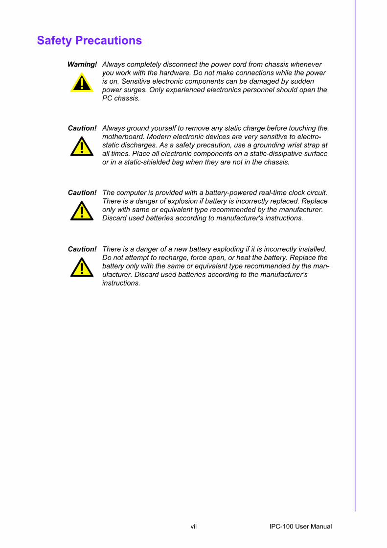
Warning! Always completely disconnect the power cord from chassis whenever you work with the hardware. Do not make connections while the power is on. Sensitive electronic components can be damaged by sudden power surges. Only experienced electronics personnel should open the PC chassis.
Caution! Always ground yourself to remove any static charge before touching the motherboard. Modern electronic devices are very sensitive to electro-static discharges. As a safety precaution, use a grounding wrist strap at all times. Place all electronic components on a static-dissipative surface or in a static-shielded bag when they are not in the chassis.
Caution! The computer is provided with a battery-powered real-time clock circuit. There is a danger of explosion if battery is incorrectly replaced. Replace only with same or equivalent type recommended by the manufacturer. Discard used batteries according to manufacturer's instructions.
Caution! There is a danger of a new battery exploding if it is incorrectly installed. Do not attempt to recharge, force open, or heat the battery. Replace the battery only with the same or equivalent type recommended by the man-ufacturer. Discard used batteries according to the manufacturer�s instructions.
vii IPC-100 User Manual

IPC-100 User Manual viii
1.1 Introduction ............................................................................................... 21.2 Specifications ............................................................................................ 21.3 Memory Compatibility................................................................................ 31.4 Environmental Specifications .................................................................... 4
Table 1.1: Environment specifications......................................... 41.5 Dimension Diagram................................................................................... 5
Figure 1.1 Dimension diagram..................................................... 5
Chapter 2 System Setup.......................................72.1 Removing the Chassis Cover.................................................................... 8
Figure 2.1 Removing the chassis top cover................................. 82.2 Installing the SODIMM .............................................................................. 92.3 Installing a Riser Card & Add-on Card ...................................................... 9
Figure 2.2 Installing a riser card and add-on card ....................... 92.4 Installing Disk Drives............................................................................... 10
Figure 2.3 Installing 2.5" HDD ................................................... 10Figure 2.4 Installing the slim-type optical disk drive .................. 10
2.5 Attaching the Mounting Ears ................................................................... 11Figure 2.5 Installing the mounting ears...................................... 11
Chapter 3 Motherboard Overview......................133.1 Board layout ............................................................................................ 14
Figure 3.1 Motherboard layout................................................... 14Figure 3.2 Rear I/O Connectors................................................. 14
3.2 Jumpers and Connectors ........................................................................ 15Table 3.1: Jumpers.................................................................... 15Table 3.2: Connectors ............................................................... 15
3.3 Motherboard Diagram ............................................................................. 16Figure 3.3 Motherboard Diagram............................................... 16
3.4 Jumper Settings ...................................................................................... 163.4.1 How to Set Jumpers.................................................................... 163.4.2 CMOS Clear (CMOS1) ............................................................... 17
Table 3.3: CMOS1..................................................................... 173.4.3 COM2 RS 232/422/485 Mode Selector (JSETCOM2)................ 17
Table 3.4: COM2 RS 232/422/485 Mode Selector (JSETCOM2) ............................................................ 17
3.4.4 J1: LCD Power 3.3 V/5 V Selector.............................................. 18Table 3.5: J1: LCD Power 3.3 V/5 V Selector ........................... 18
3.4.5 PSON1: ATX, AT Mode Selector ................................................ 18Table 3.6: PSON1: ATX, AT Mode Selector.............................. 18
3.4.6 JWDT1: Watchdog Timer Output Option .................................... 18Table 3.7: JWDT1: Watchdog Timer Output Option.................. 18
3.5 I/O Connections ...................................................................................... 193.5.1 USB Ports (LAN1_USB12/LAN2_USB34/USB56/USB78) ......... 19
Table 3.8: LAN LED Indicator.................................................... 193.5.2 VGA Connector (VGA1).............................................................. 203.5.3 Serial Ports (COM1~COM3) ....................................................... 213.5.4 PS/2 Keyboard and Mouse Connector (KBMS1)........................ 223.5.5 CPU Fan Connector (CPU_FAN1) ............................................. 223.5.6 System FAN Connector (SYSFAN1) .......................................... 23
ix IPC-100 User Manual
3.5.7 Front Panel Connectors (JFP1/JFP1+JFP2) .............................. 23Table 3.9: ATX power supply LED status
(No support for AT power)........................................ 243.5.8 Line Out, Mic In Connector (AUDIO1) ........................................ 253.5.9 Serial ATA Interface (SATA1, SATA2) ....................................... 253.5.10 PCI Slot....................................................................................... 263.5.11 Front Headphone Connector (HD1)............................................ 273.5.12 ATX 12V Power Connector (ATX12V)........................................ 283.5.13 SPI Flash connector(SPI_CN1) .................................................. 28
Chapter 4 Operation ........................................... 294.1 The System Front Panel ......................................................................... 30
4.1.1 Switch, Button and I/O Interfaces ............................................... 304.1.2 LED Indicators for System Status............................................... 30
4.2 Replacing the Motherboard..................................................................... 30Figure 4.1 Replacing the motherboard ...................................... 30
4.3 Replacing the Power Board .................................................................... 31Figure 4.2 Replacing the power board ...................................... 31
Chapter 5 BIOS Operation ................................. 335.1 Introduction ............................................................................................. 345.2 BIOS Setup ............................................................................................. 34
5.2.1 Main Menu.................................................................................. 355.2.2 Advanced BIOS Features ........................................................... 365.2.3 CPU Configuration...................................................................... 375.2.4 IDE Configuration ....................................................................... 385.2.5 Hardware Health Configuration .................................................. 405.2.6 ACPI Setting ............................................................................... 415.2.7 General ACPI Configuration ....................................................... 415.2.8 Advanced ACPI Configuration .................................................... 425.2.9 Chipset ACPI Configuration........................................................ 435.2.10 APM Configuration...................................................................... 445.2.11 USB Configuration ...................................................................... 455.2.12 USB Mass Storage Device Configuration................................... 465.2.13 Advanced PCI/PnP Settings ....................................................... 465.2.14 Boot Settings .............................................................................. 475.2.15 Boot settings Configuration......................................................... 485.2.16 Security Setup ............................................................................ 495.2.17 Advanced Chipset Settings......................................................... 495.2.18 North Bridge Chipset Configuration ............................................ 505.2.19 Video Function Configuration ..................................................... 515.2.20 South Bridge Chipset Configuration ........................................... 525.2.21 Exit Option .................................................................................. 53
Chapter 6 Software Introduction & Service ..... 556.1 Introduction ............................................................................................. 566.2 Value-Added Software Services ............................................................. 56
6.2.1 Software API............................................................................... 566.2.2 Software Utility............................................................................ 58
IPC-100 User Manual x
Chapter 8 VGA Setup..........................................638.1 Introduction ............................................................................................. 648.2 Windows 7/Vista/XP................................................................................ 64
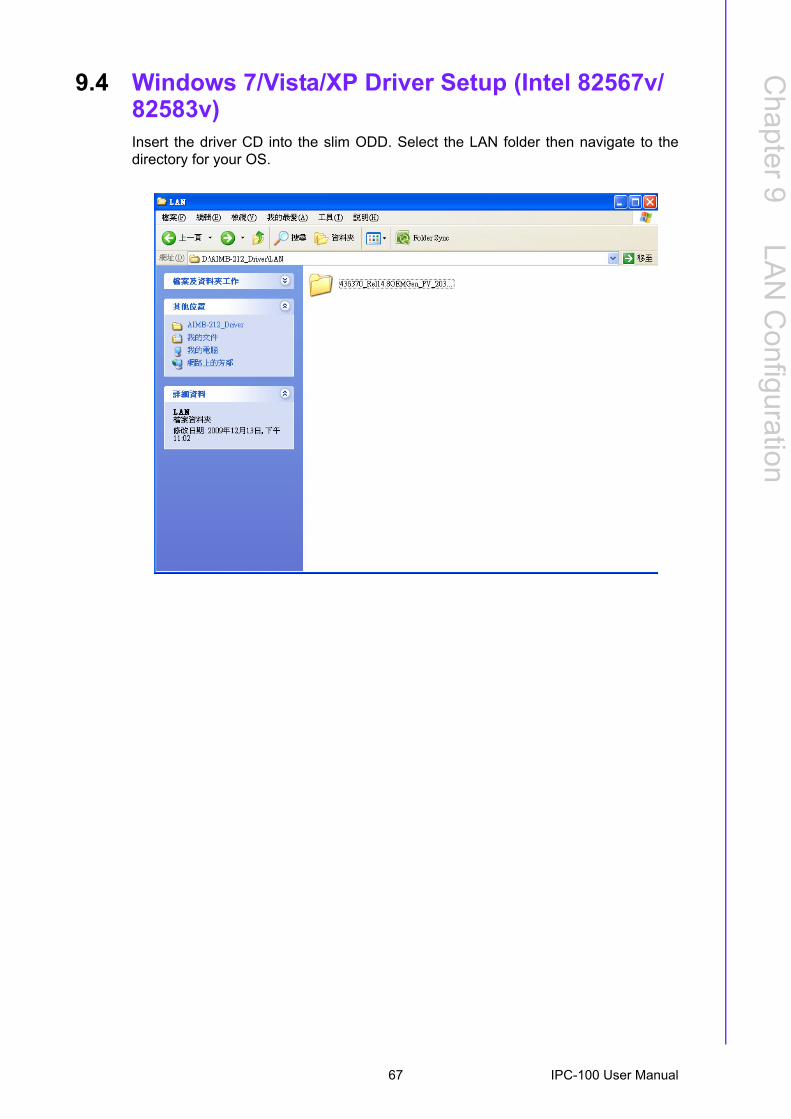
Chapter 9 LAN Configuration.............................659.1 Introduction ............................................................................................. 669.2 Features .................................................................................................. 669.3 Installation ............................................................................................... 669.4 Windows 7/Vista/XP Driver Setup (Intel 82567v/82583v) ....................... 67
Appendix A Exploded Diagram .............................69A.1 Exploded Diagram................................................................................... 70
Figure A.1 Exploded diagram..................................................... 70
Appendix B Programming the Watchdog Timer..71B.1 Programming the Watchdog Timer ......................................................... 72
B.1.1 Watchdog Timer Overview.......................................................... 72B.1.2 Programming the Watchdog Timer ............................................. 72
Table B.1: Watchdog Timer Registers ....................................... 74B.1.3 Example Program ....................................................................... 75
Appendix C I/O Pin Assignments..........................79C.1 USB Header (USB56, USB78)................................................................ 80
Table C.1: USB Header (USB56)............................................... 80C.2 VGA Connector (VGA1) .......................................................................... 80
Table C.2: VGA Connector (VGA1) ........................................... 80C.3 RS-232 Interface ..................................................................................... 81
Table C.3: RS-232 Interface (COM4~COM6) ............................ 81C.4 RS-232/422/485 Setting Interface (JETCOM2)....................................... 81
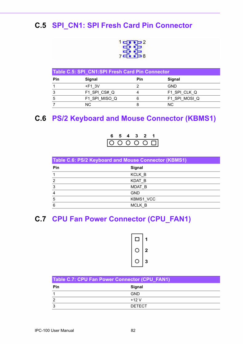
Table C.4: RS-232/422/485 Setting Interface (JETCOM2) ........ 81C.5 SPI_CN1: SPI Fresh Card Pin Connector............................................... 82
Table C.5: SPI_CN1:SPI Fresh Card Pin Connector ................. 82C.6 PS/2 Keyboard and Mouse Connector (KBMS1) .................................... 82
Table C.6: PS/2 Keyboard and Mouse Connector (KBMS1) ..... 82C.7 CPU Fan Power Connector (CPU_FAN1) .............................................. 82
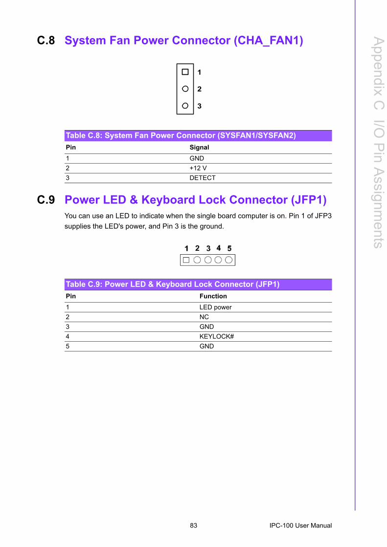
Table C.7: CPU Fan Power Connector (CPU_FAN1)................ 82C.8 System Fan Power Connector (CHA_FAN1) .......................................... 83
Table C.8: System Fan Power Connector (SYSFAN1/SYSFAN2).................................................................................. 83
C.9 Power LED & Keyboard Lock Connector (JFP1) .................................... 83Table C.9: Power LED & Keyboard Lock Connector (JFP1)...... 83
C.10 Power switch/HDD LED/SMBus/Speaker (JFP1+JFP2) ......................... 84Table C.10:Power Switch/HDD LED/SMBus/Speaker
(JFP1+JFP2) ............................................................ 84
xi IPC-100 User Manual
C.11 USB/LAN ports (LAN1_USB12/LAN2_USB34) ...................................... 84Table C.11:USB Port .................................................................. 84Table C.12:Ethernet 10/100 Mbps RJ-45 Port............................ 84
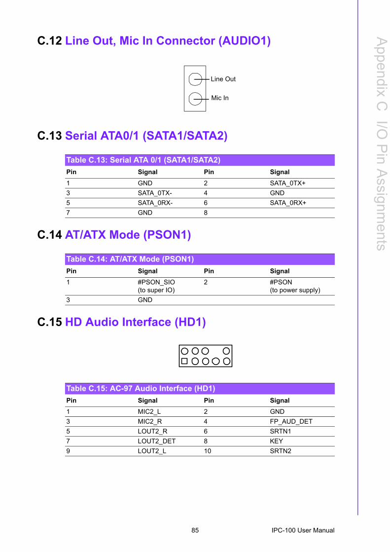
C.12 Line Out, Mic In Connector (AUDIO1) .................................................... 85C.13 Serial ATA0/1 (SATA1/SATA2)............................................................... 85
Table C.13:Serial ATA 0/1 (SATA1/SATA2)............................... 85C.14 AT/ATX Mode (PSON1).......................................................................... 85
Table C.14:AT/ATX Mode (PSON1) ........................................... 85C.15 HD Audio Interface (HD1) ....................................................................... 85
Table C.15:AC-97 Audio Interface (HD1) ................................... 85C.16 ATX 12 V connector (ATX12V_1) ........................................................... 86
Table C.16:ATX 12 V connector (ATX12V_1) ............................ 86C.17 DMA Channel Assignments .................................................................... 86
Table C.17:DMA Channel Assignments ..................................... 86C.18 Interrupt Assignments ............................................................................. 87
Table C.18:Interrupt Assignments .............................................. 87C.19 1st MB Memory Map............................................................................... 87
Table C.19:1st MB Memory Map ................................................ 87
IPC-100 User Manual xii

Chapter 1
1 General Information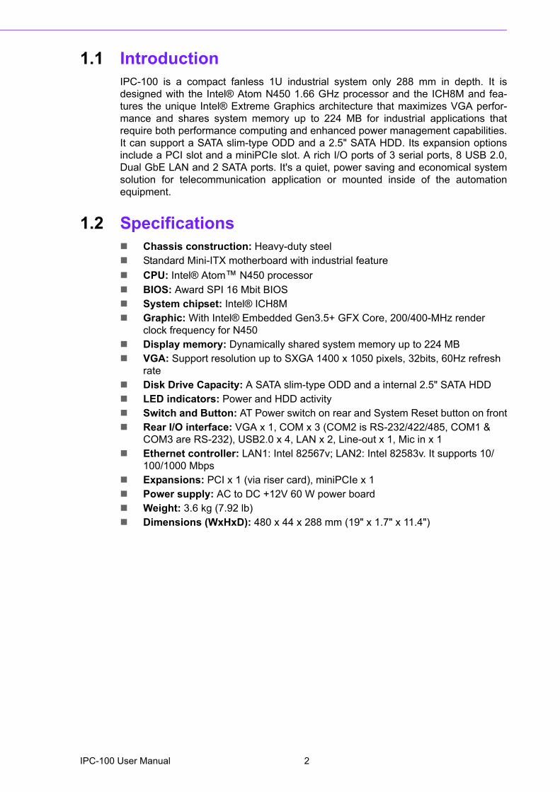
1.1 IntroductionIPC-100 is a compact fanless 1U industrial system only 288 mm in depth. It isdesigned with the Intel® Atom N450 1.66 GHz processor and the ICH8M and fea-tures the unique Intel® Extreme Graphics architecture that maximizes VGA perfor-mance and shares system memory up to 224 MB for industrial applications thatrequire both performance computing and enhanced power management capabilities.It can support a SATA slim-type ODD and a 2.5" SATA HDD. Its expansion optionsinclude a PCI slot and a miniPCIe slot. A rich I/O ports of 3 serial ports, 8 USB 2.0,Dual GbE LAN and 2 SATA ports. It's a quiet, power saving and economical systemsolution for telecommunication application or mounted inside of the automationequipment.
1.2 Specifications! Chassis construction: Heavy-duty steel! Standard Mini-ITX motherboard with industrial feature! CPU: Intel® Atom� N450 processor! BIOS: Award SPI 16 Mbit BIOS! System chipset: Intel® ICH8M! Graphic: With Intel® Embedded Gen3.5+ GFX Core, 200/400-MHz render
clock frequency for N450! Display memory: Dynamically shared system memory up to 224 MB! VGA: Support resolution up to SXGA 1400 x 1050 pixels, 32bits, 60Hz refresh
rate! Disk Drive Capacity: A SATA slim-type ODD and a internal 2.5" SATA HDD! LED indicators: Power and HDD activity ! Switch and Button: AT Power switch on rear and System Reset button on front! Rear I/O interface: VGA x 1, COM x 3 (COM2 is RS-232/422/485, COM1 &
COM3 are RS-232), USB2.0 x 4, LAN x 2, Line-out x 1, Mic in x 1! Ethernet controller: LAN1: Intel 82567v; LAN2: Intel 82583v. It supports 10/
100/1000 Mbps ! Expansions: PCI x 1 (via riser card), miniPCIe x 1! Power supply: AC to DC +12V 60 W power board ! Weight: 3.6 kg (7.92 lb)! Dimensions (WxHxD): 480 x 44 x 288 mm (19" x 1.7" x 11.4")
IPC-100 User Manual 2
Chapter 1
GeneralInform
ation
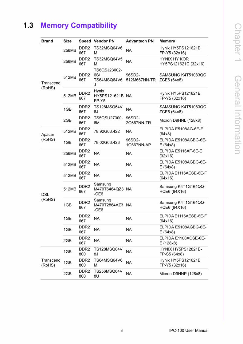
1.3 Memory Compatibility
Brand Size Speed Vendor PN Advantech PN Memory
Transcend(RoHS)
256MB DDR2 667
TS32MSQ64V6M NA Hynix HY5PS121621B
FP-Y5 (32x16)
256MB DDR2 667
TS32MSQ64V5M NA HYNIX HY KOR
HY5PS121621C (32x16)
512MB DDR2 667
TS6QSJ23002-6S/TS64MSQ64V6J
96SD2-512M667NN-TR
SAMSUNG K4T51083QC ZCE6 (64x8)
512MB DDR2 667
Hynix HY5PS121621B FP-Y5
NA Hynix HY5PS121621B FP-Y5 (32x16)
1GB DDR2 667
TS128MSQ64V6J NA SAMSUNG K4T51083QC
ZCE6 (64x8)
2GB DDR2 667
TS5QSU27300-6M
96SD2-2G667NN-TR Micron D9HNL (128x8)
Apacer(RoHS)
512MB DDR2 667 78.92G63.422 NA ELPIDA E5108AG-6E-E
(64x8)
1GB DDR2 667 78.02G63.423 96SD2-
1G667NN-APELPIDA E5108AGBG-6E-E (64x8)
DSL (RoHS)
256MB DDR2 667 NA NA ELPIDA E5116AF-6E-E
(32x16)
512MB DDR2 667 NA NA ELPIDA E5108AGBG-6E-
E (64x8)
512MB DDR2 667 NA NA ELPIDA E1116AESE-6E-F
(64x16)
512MB DDR2 667
Samsung M470T6464QZ3-CE6
NA Samsung K4T1G164QQ-HCE6 (64X16)
1GB DDR2 667
Samsung M470T2864AZ3-CE6
NA Samsung K4T1G164QQ-HCE6 (64X16)
1GB DDR2 667 NA NA ELPIDA E1116AESE-6E-F
(64x16)
1GB DDR2 667 NA NA ELPIDA E5108AGBG-6E-
E (64x8)
2GB DDR2 667 NA NA ELPIDA E1108ACSE-6E-
E (128x8)
Transcend(RoHS)
1GB DDR2 800
TS128MSQ64V8J NA HYNIX HY5PS12821E-
FP-S5 (64x8)
1GB DDR2 800
TS64MSQ64V6M NA Hynix HY5PS121621B
FP-Y5 (32x16)
2GB DDR2 800
TS256MSQ64V8U NA Micron D9HNP (128x8)
3 IPC-100 User Manual
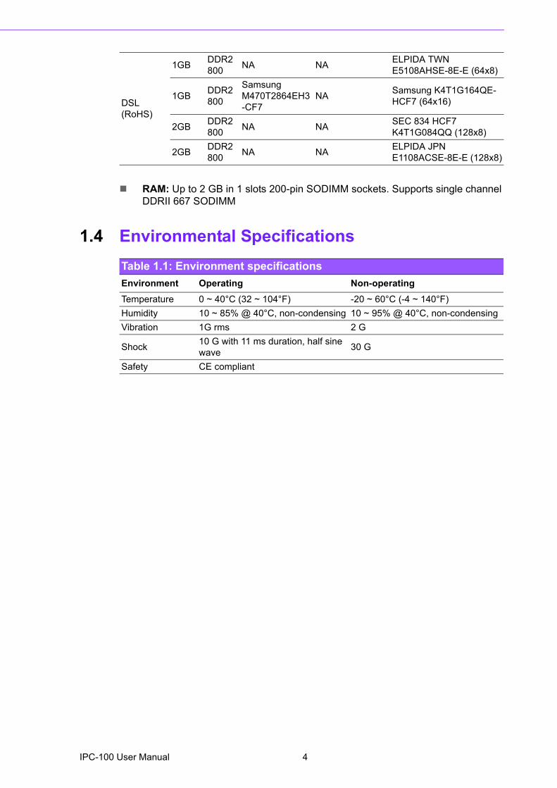
! RAM: Up to 2 GB in 1 slots 200-pin SODIMM sockets. Supports single channel DDRII 667 SODIMM
1.4 Environmental Specifications
DSL (RoHS)
1GB DDR2 800 NA NA ELPIDA TWN
E5108AHSE-8E-E (64x8)
1GB DDR2 800
Samsung M470T2864EH3-CF7
NA Samsung K4T1G164QE-HCF7 (64x16)
2GB DDR2 800 NA NA SEC 834 HCF7
K4T1G084QQ (128x8)
2GB DDR2 800 NA NA ELPIDA JPN
E1108ACSE-8E-E (128x8)
Table 1.1: Environment specificationsEnvironment Operating Non-operatingTemperature 0 ~ 40°C (32 ~ 104°F) -20 ~ 60°C (-4 ~ 140°F)Humidity 10 ~ 85% @ 40°C, non-condensing 10 ~ 95% @ 40°C, non-condensingVibration 1G rms 2 G
Shock 10 G with 11 ms duration, half sine wave 30 G
Safety CE compliant
IPC-100 User Manual 4
Chapter 1
GeneralInform
ation
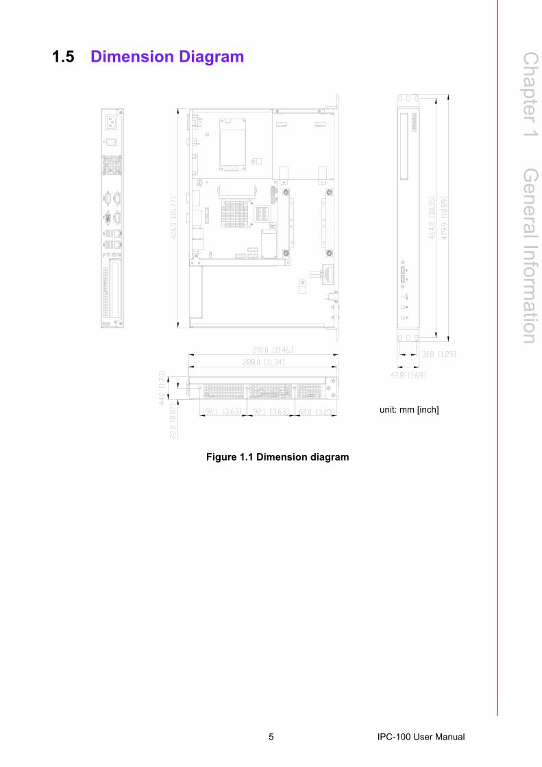
1.5 Dimension Diagram
Figure 1.1 Dimension diagram
unit: mm [inch]
5 IPC-100 User Manual

IPC-100 User Manual 6

Chapter 2
2 System Setup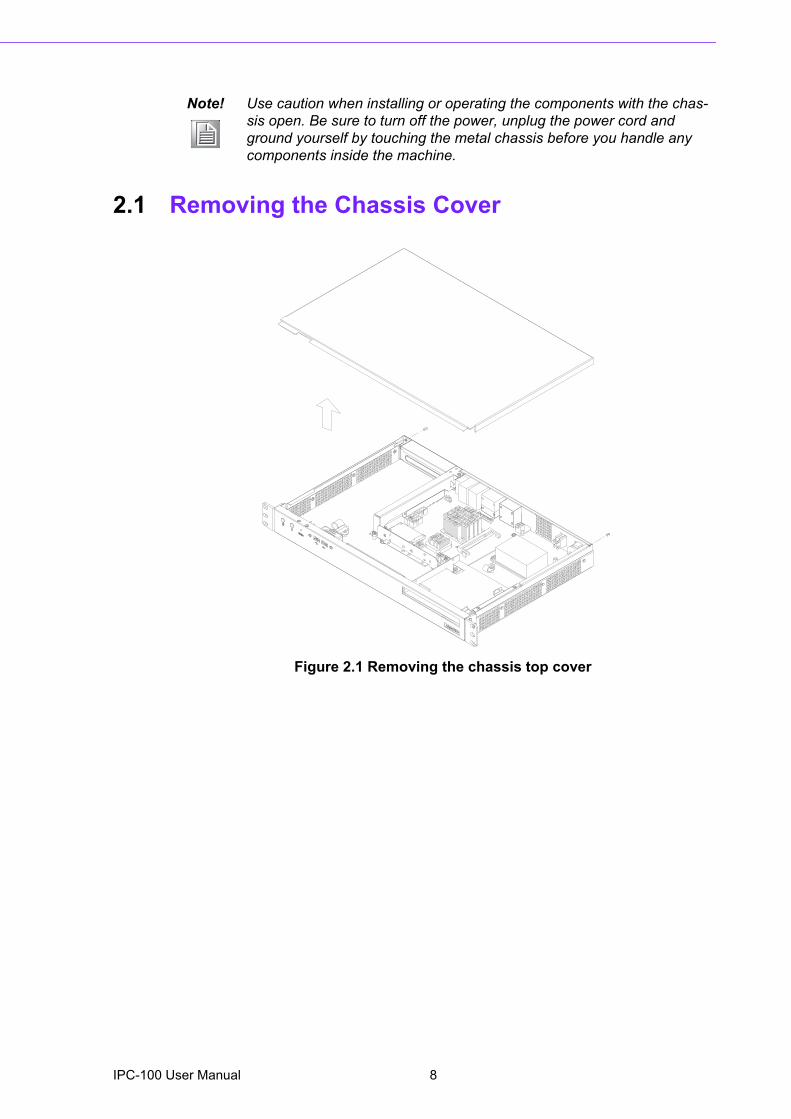
2.1 Removing the Chassis Cover
Figure 2.1 Removing the chassis top cover
Note! Use caution when installing or operating the components with the chas-sis open. Be sure to turn off the power, unplug the power cord and ground yourself by touching the metal chassis before you handle any components inside the machine.
IPC-100 User Manual 8
Chapter 2
System
Setup
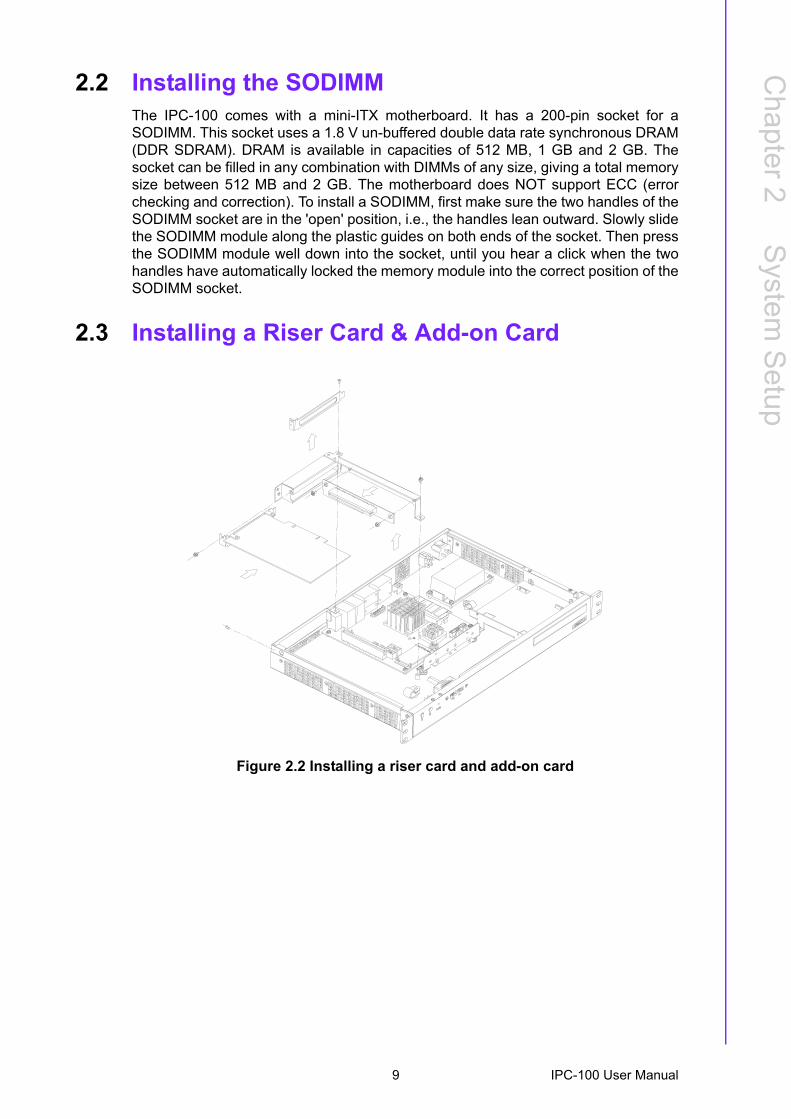
2.2 Installing the SODIMMThe IPC-100 comes with a mini-ITX motherboard. It has a 200-pin socket for aSODIMM. This socket uses a 1.8 V un-buffered double data rate synchronous DRAM(DDR SDRAM). DRAM is available in capacities of 512 MB, 1 GB and 2 GB. Thesocket can be filled in any combination with DIMMs of any size, giving a total memorysize between 512 MB and 2 GB. The motherboard does NOT support ECC (errorchecking and correction). To install a SODIMM, first make sure the two handles of theSODIMM socket are in the 'open' position, i.e., the handles lean outward. Slowly slidethe SODIMM module along the plastic guides on both ends of the socket. Then pressthe SODIMM module well down into the socket, until you hear a click when the twohandles have automatically locked the memory module into the correct position of theSODIMM socket.
2.3 Installing a Riser Card & Add-on Card
Figure 2.2 Installing a riser card and add-on card
9 IPC-100 User Manual
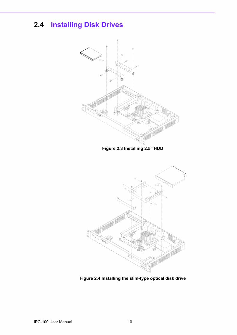
2.4 Installing Disk Drives
Figure 2.3 Installing 2.5" HDD
Figure 2.4 Installing the slim-type optical disk drive
IPC-100 User Manual 10
Chapter 2
System
Setup
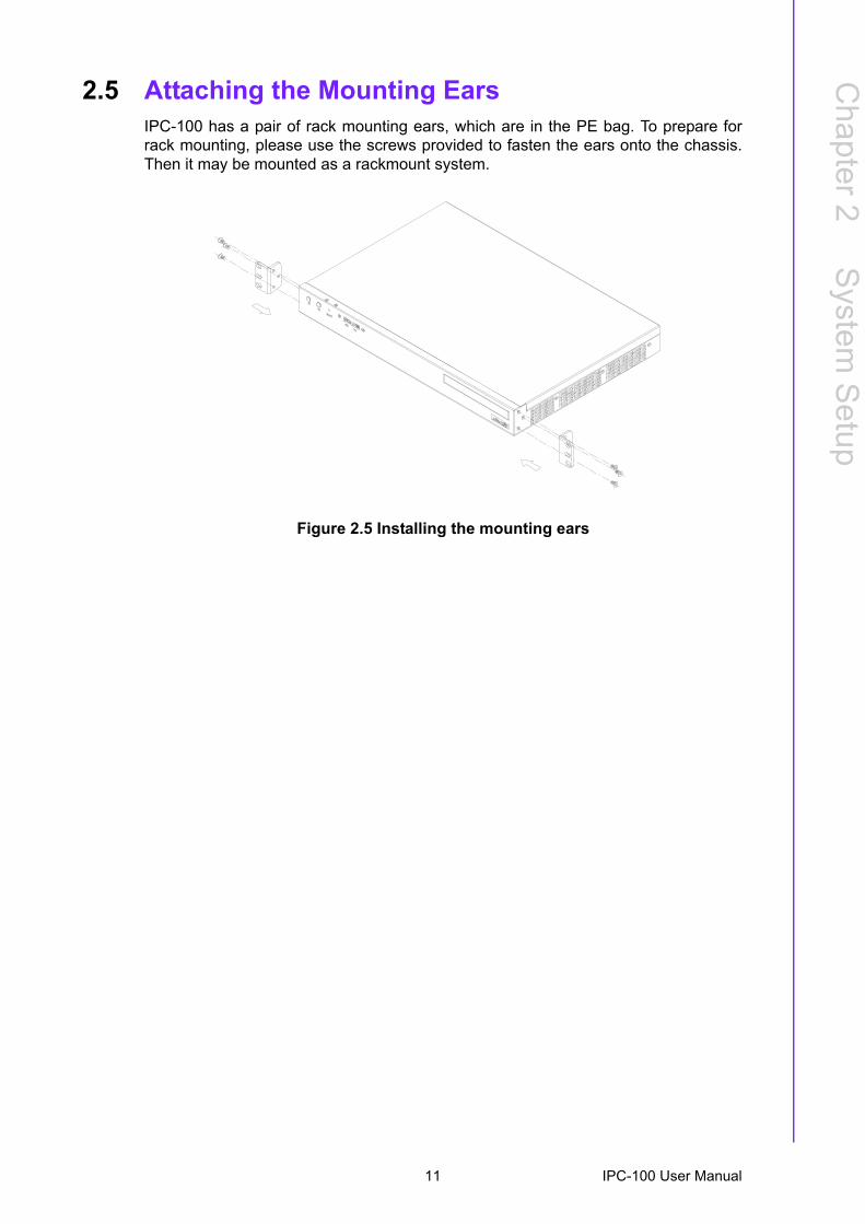
2.5 Attaching the Mounting EarsIPC-100 has a pair of rack mounting ears, which are in the PE bag. To prepare forrack mounting, please use the screws provided to fasten the ears onto the chassis.Then it may be mounted as a rackmount system.
Figure 2.5 Installing the mounting ears
11 IPC-100 User Manual

IPC-100 User Manual 12

Chapter 3
3 Motherboard Overview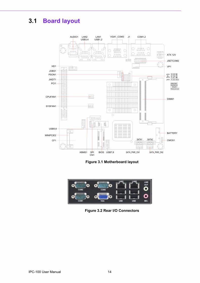
3.1 Board layout
Figure 3.1 Motherboard layout
Figure 3.2 Rear I/O Connectors
SPI
CN1
VP1
DIMM1
CMOS1
BATTERY
BIOSKBMS1 USB7,8
JSETCOM2
ATX 12V
PCI1
CPUFAN1
SYSFAN1
SATA_PWR_CN1 SATA_PWR_CN2
SATA1 SATA2
USB5,6
MINIPCIE2
CF1
HD1
JWDT1
JOBS1
PSON1
1J1OIDUA LAN2
USB3,4
LAN1
USB1,2
VGA1_COM3 COM1,2
JFP1&
JFP2
JFP1
3 6 9 12
TESERWSRWP
1 2 3 4 5
2 5 8 11
1 4 7 10
KCOLYEK&DELRWP
REKAEPS
SUB_MSDELDDH
IPC-100 User Manual 14
Chapter 3
Motherboard
Overview
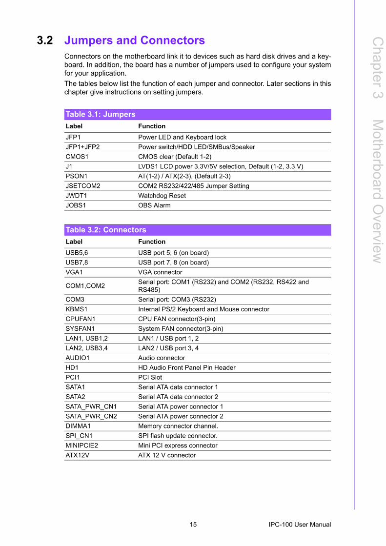
3.2 Jumpers and ConnectorsConnectors on the motherboard link it to devices such as hard disk drives and a key-board. In addition, the board has a number of jumpers used to configure your systemfor your application.The tables below list the function of each jumper and connector. Later sections in thischapter give instructions on setting jumpers.
Table 3.1: JumpersLabel FunctionJFP1 Power LED and Keyboard lockJFP1+JFP2 Power switch/HDD LED/SMBus/SpeakerCMOS1 CMOS clear (Default 1-2)J1 LVDS1 LCD power 3.3V/5V selection, Default (1-2, 3.3 V)PSON1 AT(1-2) / ATX(2-3), (Default 2-3)JSETCOM2 COM2 RS232/422/485 Jumper SettingJWDT1 Watchdog ResetJOBS1 OBS Alarm
Table 3.2: ConnectorsLabel FunctionUSB5,6 USB port 5, 6 (on board)USB7,8 USB port 7, 8 (on board)VGA1 VGA connector
COM1,COM2 Serial port: COM1 (RS232) and COM2 (RS232, RS422 and RS485)
COM3 Serial port: COM3 (RS232)KBMS1 Internal PS/2 Keyboard and Mouse connectorCPUFAN1 CPU FAN connector(3-pin)SYSFAN1 System FAN connector(3-pin)LAN1, USB1,2 LAN1 / USB port 1, 2LAN2, USB3,4 LAN2 / USB port 3, 4AUDIO1 Audio connectorHD1 HD Audio Front Panel Pin HeaderPCI1 PCI SlotSATA1 Serial ATA data connector 1SATA2 Serial ATA data connector 2SATA_PWR_CN1 Serial ATA power connector 1SATA_PWR_CN2 Serial ATA power connector 2DIMMA1 Memory connector channel.SPI_CN1 SPI flash update connector.MINIPCIE2 Mini PCI express connectorATX12V ATX 12 V connector
15 IPC-100 User Manual
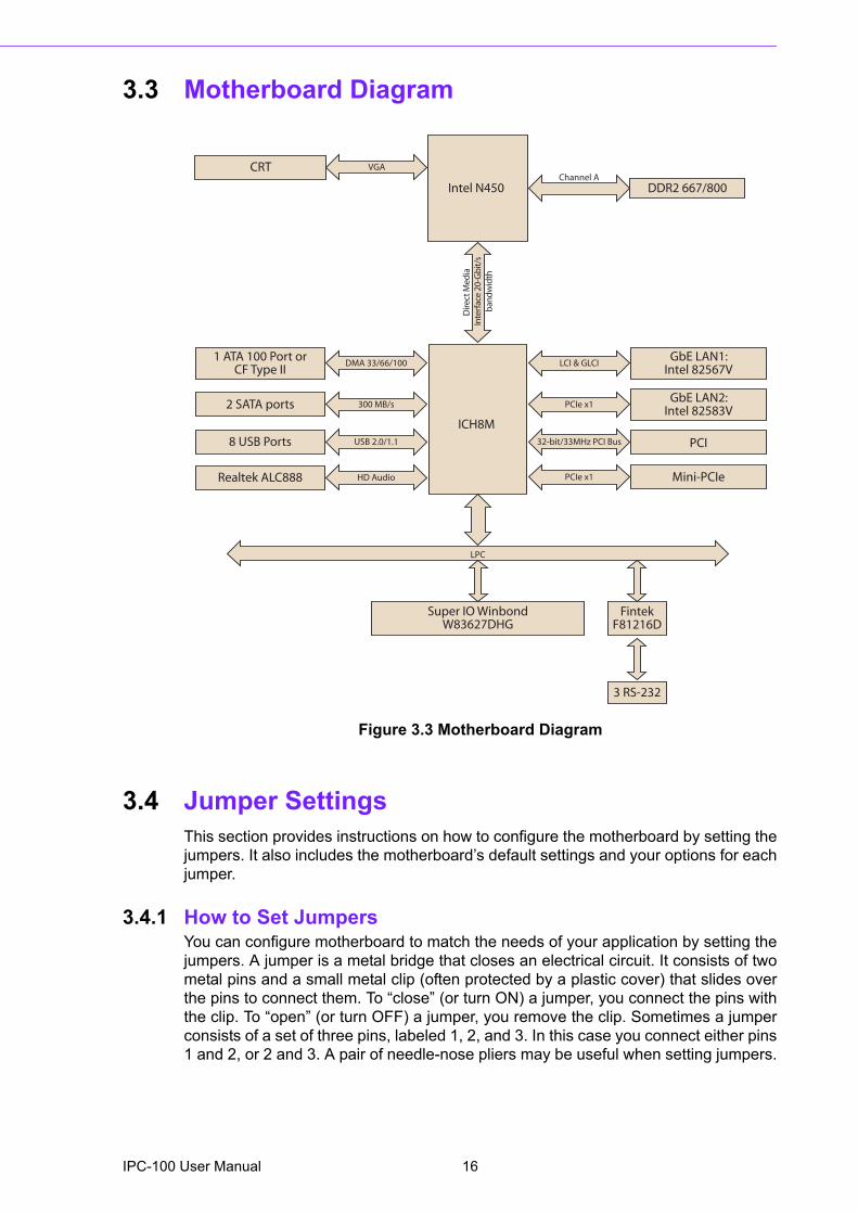
3.3 Motherboard Diagram
Figure 3.3 Motherboard Diagram
3.4 Jumper SettingsThis section provides instructions on how to configure the motherboard by setting thejumpers. It also includes the motherboard�s default settings and your options for eachjumper.
3.4.1 How to Set JumpersYou can configure motherboard to match the needs of your application by setting thejumpers. A jumper is a metal bridge that closes an electrical circuit. It consists of twometal pins and a small metal clip (often protected by a plastic cover) that slides overthe pins to connect them. To �close� (or turn ON) a jumper, you connect the pins withthe clip. To �open� (or turn OFF) a jumper, you remove the clip. Sometimes a jumperconsists of a set of three pins, labeled 1, 2, and 3. In this case you connect either pins1 and 2, or 2 and 3. A pair of needle-nose pliers may be useful when setting jumpers.
ICH8M
FintekF81216D
3 RS-232
LPC
Super IO WinbondW83627DHG
Intel N450 DDR2 667/800Channel A
Dire
ctM
edia
Inte
rfac
e 20
-Gb
it/s
ban
dwid
th
CRT VGA
1 ATA 100 Port orCF Type II
2 SATA ports
8 USB Ports
Realtek ALC888
300 MB/s
DMA 33/66/100
USB 2.0/1.1
HD Audio
GbE LAN1:Intel 82567V
GbE LAN2:Intel 82583V
PCI
LCI & GLCI
PCIe x1
32-bit/33MHz PCI Bus
PCIe x1 Mini-PCIe
IPC-100 User Manual 16
Chapter 3
Motherboard
Overview
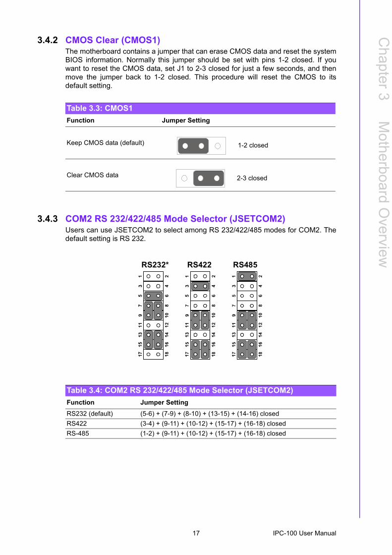
3.4.2 CMOS Clear (CMOS1)The motherboard contains a jumper that can erase CMOS data and reset the systemBIOS information. Normally this jumper should be set with pins 1-2 closed. If youwant to reset the CMOS data, set J1 to 2-3 closed for just a few seconds, and thenmove the jumper back to 1-2 closed. This procedure will reset the CMOS to itsdefault setting.
3.4.3 COM2 RS 232/422/485 Mode Selector (JSETCOM2)Users can use JSETCOM2 to select among RS 232/422/485 modes for COM2. Thedefault setting is RS 232.
Table 3.3: CMOS1Function Jumper Setting
Keep CMOS data (default)
Clear CMOS data
1-2 closed
2-3 closed
Table 3.4: COM2 RS 232/422/485 Mode Selector (JSETCOM2)Function Jumper SettingRS232 (default) (5-6) + (7-9) + (8-10) + (13-15) + (14-16) closedRS422 (3-4) + (9-11) + (10-12) + (15-17) + (16-18) closedRS-485 (1-2) + (9-11) + (10-12) + (15-17) + (16-18) closed
RS232* RS422 RS485
17 IPC-100 User Manual
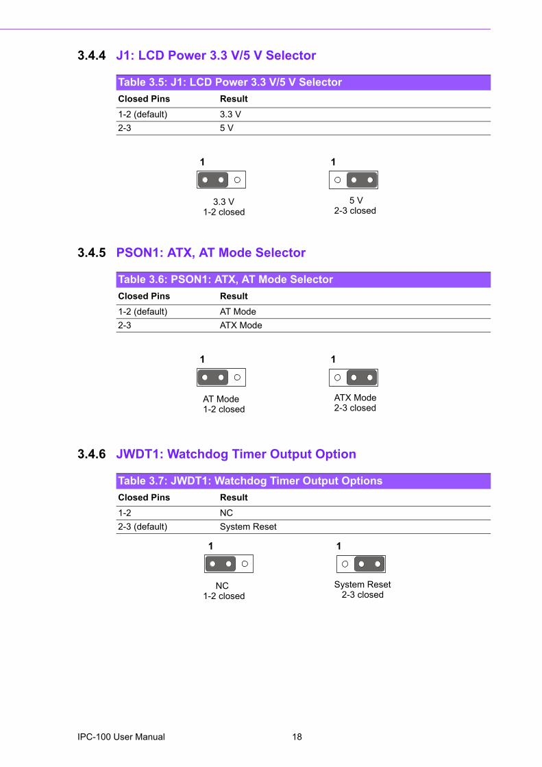
3.4.4 J1: LCD Power 3.3 V/5 V Selector
1 1
3.4.5 PSON1: ATX, AT Mode Selector
1 1
3.4.6 JWDT1: Watchdog Timer Output Option
1 1
Table 3.5: J1: LCD Power 3.3 V/5 V SelectorClosed Pins Result1-2 (default) 3.3 V2-3 5 V
3.3 V1-2 closed
5 V2-3 closed
Table 3.6: PSON1: ATX, AT Mode SelectorClosed Pins Result1-2 (default) AT Mode2-3 ATX Mode
AT Mode1-2 closed
ATX Mode2-3 closed
Table 3.7: JWDT1: Watchdog Timer Output OptionsClosed Pins Result1-2 NC2-3 (default) System Reset
NC1-2 closed
System Reset 2-3 closed
IPC-100 User Manual 18
Chapter 3
Motherboard
Overview
3.5 I/O Connections
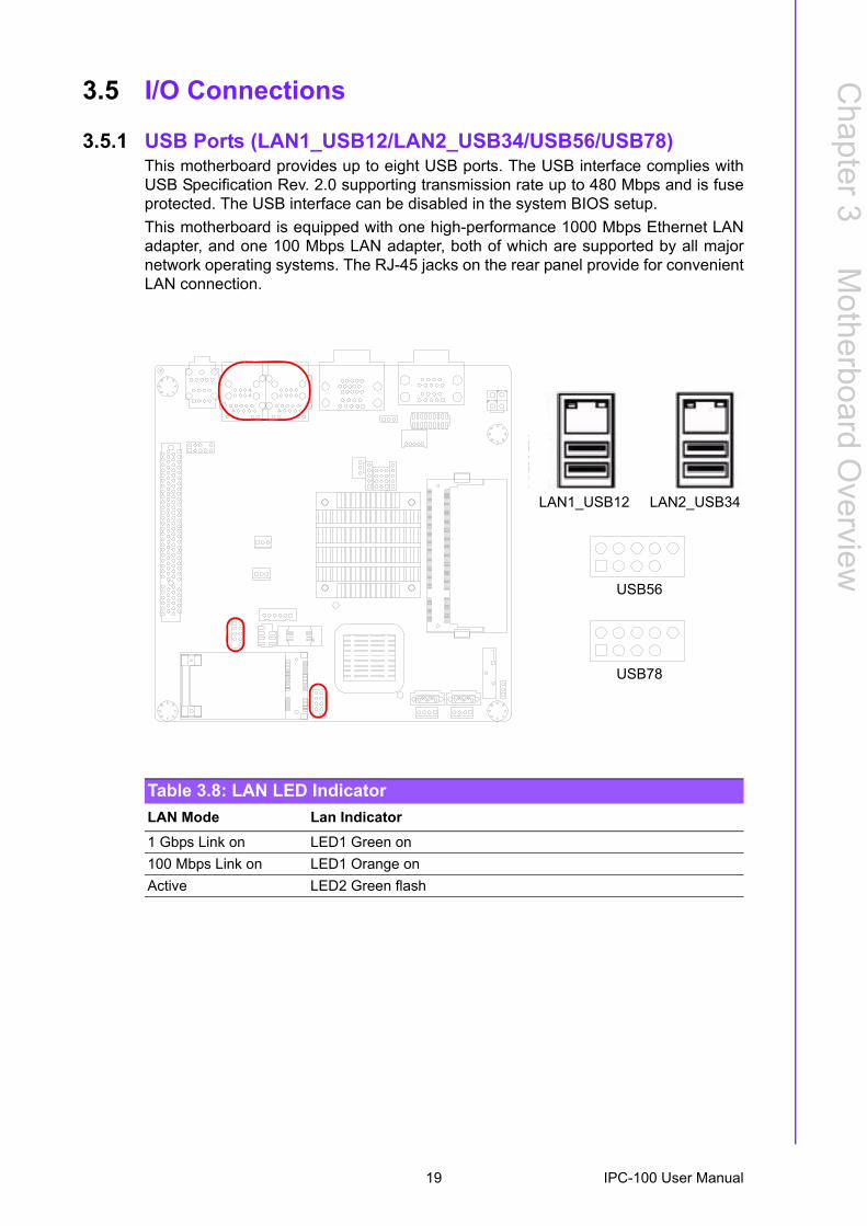
3.5.1 USB Ports (LAN1_USB12/LAN2_USB34/USB56/USB78)This motherboard provides up to eight USB ports. The USB interface complies withUSB Specification Rev. 2.0 supporting transmission rate up to 480 Mbps and is fuseprotected. The USB interface can be disabled in the system BIOS setup.This motherboard is equipped with one high-performance 1000 Mbps Ethernet LANadapter, and one 100 Mbps LAN adapter, both of which are supported by all majornetwork operating systems. The RJ-45 jacks on the rear panel provide for convenientLAN connection.
USB56
USB78
Table 3.8: LAN LED IndicatorLAN Mode Lan Indicator1 Gbps Link on LED1 Green on100 Mbps Link on LED1 Orange onActive LED2 Green flash
LAN2_USB34 LAN1_USB12LAN1_USB12 LAN2_USB34
19 IPC-100 User Manual
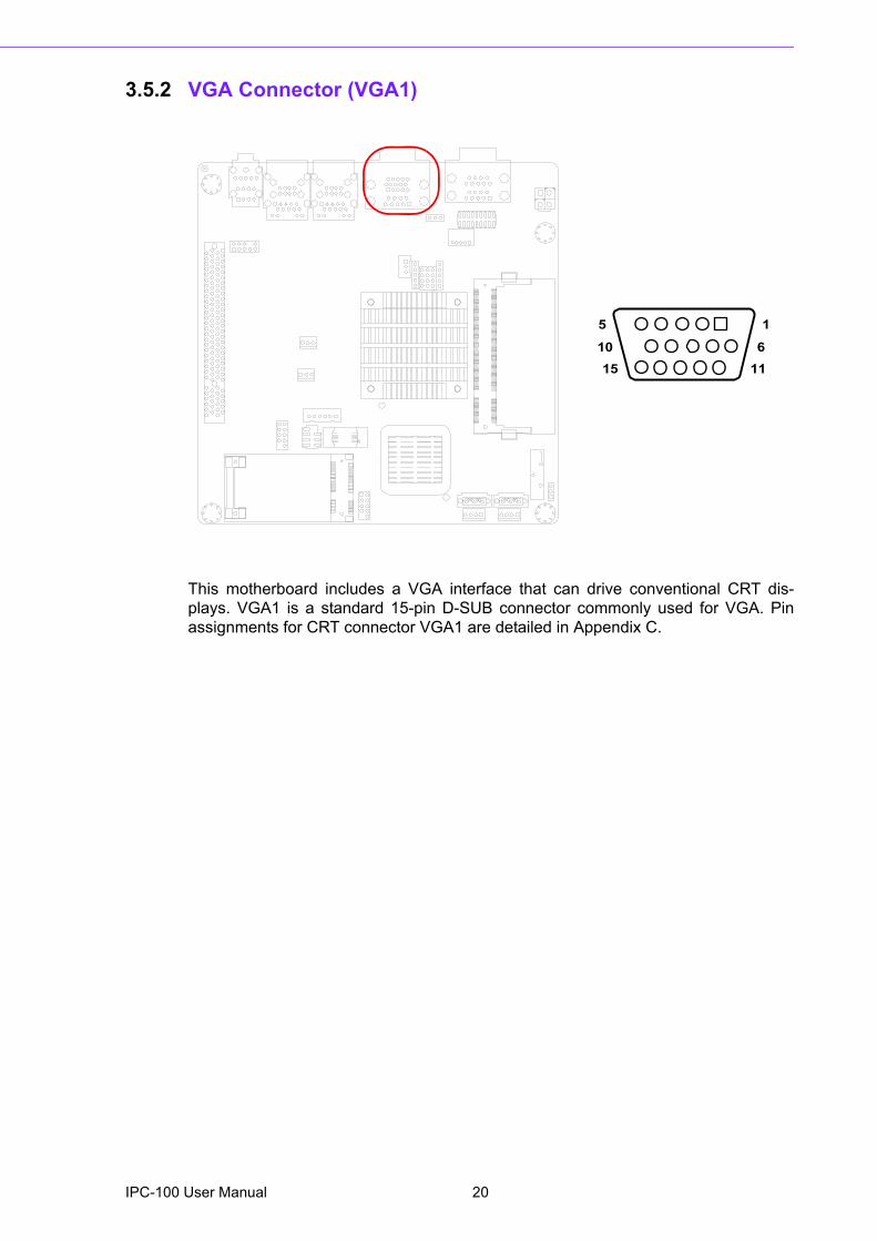
3.5.2 VGA Connector (VGA1)
This motherboard includes a VGA interface that can drive conventional CRT dis-plays. VGA1 is a standard 15-pin D-SUB connector commonly used for VGA. Pinassignments for CRT connector VGA1 are detailed in Appendix C.
5
15
1
1110 6
IPC-100 User Manual 20
Chapter 3
Motherboard
Overview
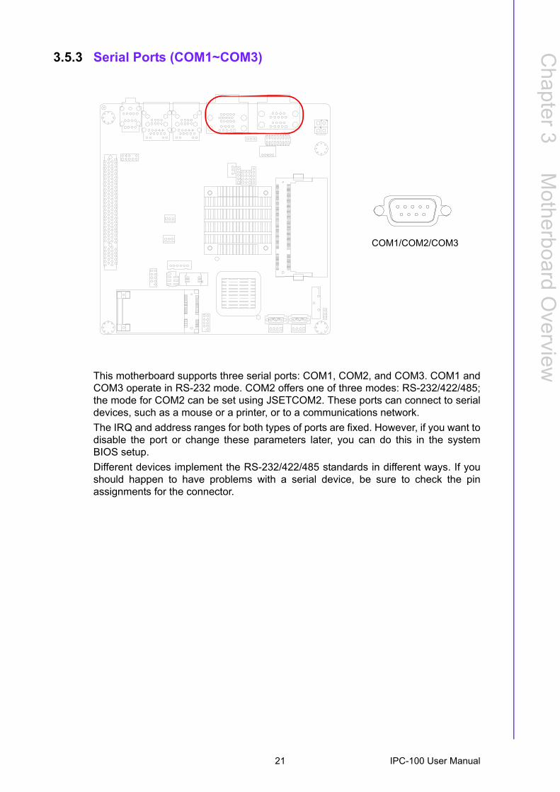
3.5.3 Serial Ports (COM1~COM3)
This motherboard supports three serial ports: COM1, COM2, and COM3. COM1 andCOM3 operate in RS-232 mode. COM2 offers one of three modes: RS-232/422/485;the mode for COM2 can be set using JSETCOM2. These ports can connect to serialdevices, such as a mouse or a printer, or to a communications network.The IRQ and address ranges for both types of ports are fixed. However, if you want todisable the port or change these parameters later, you can do this in the systemBIOS setup.Different devices implement the RS-232/422/485 standards in different ways. If youshould happen to have problems with a serial device, be sure to check the pinassignments for the connector.
COM1/COM2/COM3
21 IPC-100 User Manual
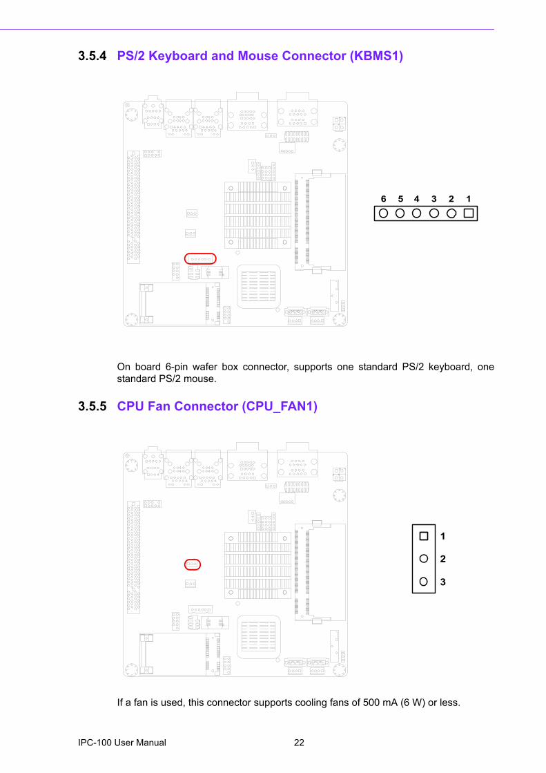
3.5.4 PS/2 Keyboard and Mouse Connector (KBMS1)
On board 6-pin wafer box connector, supports one standard PS/2 keyboard, onestandard PS/2 mouse.
3.5.5 CPU Fan Connector (CPU_FAN1)
If a fan is used, this connector supports cooling fans of 500 mA (6 W) or less.
5 4 23 16
1
2
3
IPC-100 User Manual 22
Chapter 3
Motherboard
Overview
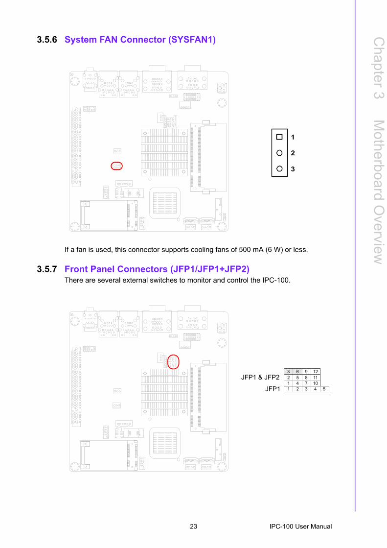
3.5.6 System FAN Connector (SYSFAN1)
If a fan is used, this connector supports cooling fans of 500 mA (6 W) or less.
3.5.7 Front Panel Connectors (JFP1/JFP1+JFP2)There are several external switches to monitor and control the IPC-100.
1
2
3
3 6 9 12
2 5 8 11
1 4 7 10
1 2 3 4 5
JFP1 & JFP2
JFP1
23 IPC-100 User Manual
3.5.7.1 ATX soft power switch ((JFP1+JFP2/ PWR_SW))If your computer case is equipped with an ATX power supply, you should connect thepower on/off button on your computer case to (JFP1+JFP2/ PWR_SW), for conve-nient power on and off.
3.5.7.2 Reset (JFP1+JFP2/ RESET)Many computer cases offer the convenience of a reset button. Connect the wire forthe reset button.
3.5.7.3 HDD LED (JFP1+JFP2/ HDDLED)You can connect an LED to connector (JFP2/HDDLED) to indicate when the HDD isactive.
3.5.7.4 External speaker (JFP1+JFP2/ SPEAKER)(JFP1+JFP2/ SPEAKER) is a 4-pin connector for an external speaker. If there is noexternal speaker, it provides an onboard buzzer as an alternative. To enable thebuzzer, set pins 3-4 as closed.
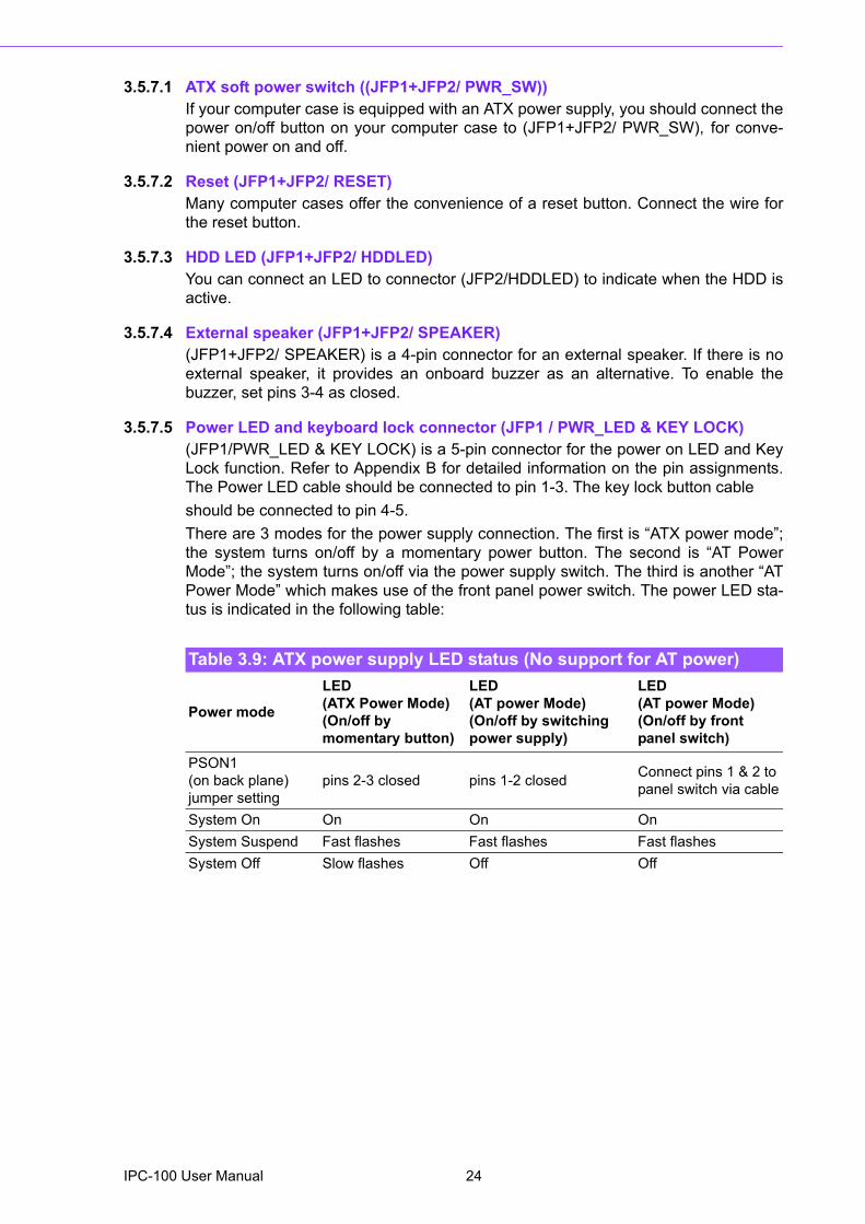
3.5.7.5 Power LED and keyboard lock connector (JFP1 / PWR_LED & KEY LOCK)(JFP1/PWR_LED & KEY LOCK) is a 5-pin connector for the power on LED and KeyLock function. Refer to Appendix B for detailed information on the pin assignments.The Power LED cable should be connected to pin 1-3. The key lock button cableshould be connected to pin 4-5. There are 3 modes for the power supply connection. The first is �ATX power mode�;the system turns on/off by a momentary power button. The second is �AT PowerMode�; the system turns on/off via the power supply switch. The third is another �ATPower Mode� which makes use of the front panel power switch. The power LED sta-tus is indicated in the following table:
Table 3.9: ATX power supply LED status (No support for AT power)
Power mode
LED (ATX Power Mode)(On/off by momentary button)
LED (AT power Mode) (On/off by switching power supply)
LED (AT power Mode) (On/off by front panel switch)
PSON1 (on back plane) jumper setting
pins 2-3 closed pins 1-2 closed Connect pins 1 & 2 to panel switch via cable
System On On On OnSystem Suspend Fast flashes Fast flashes Fast flashesSystem Off Slow flashes Off Off
IPC-100 User Manual 24
Chapter 3
Motherboard
Overview
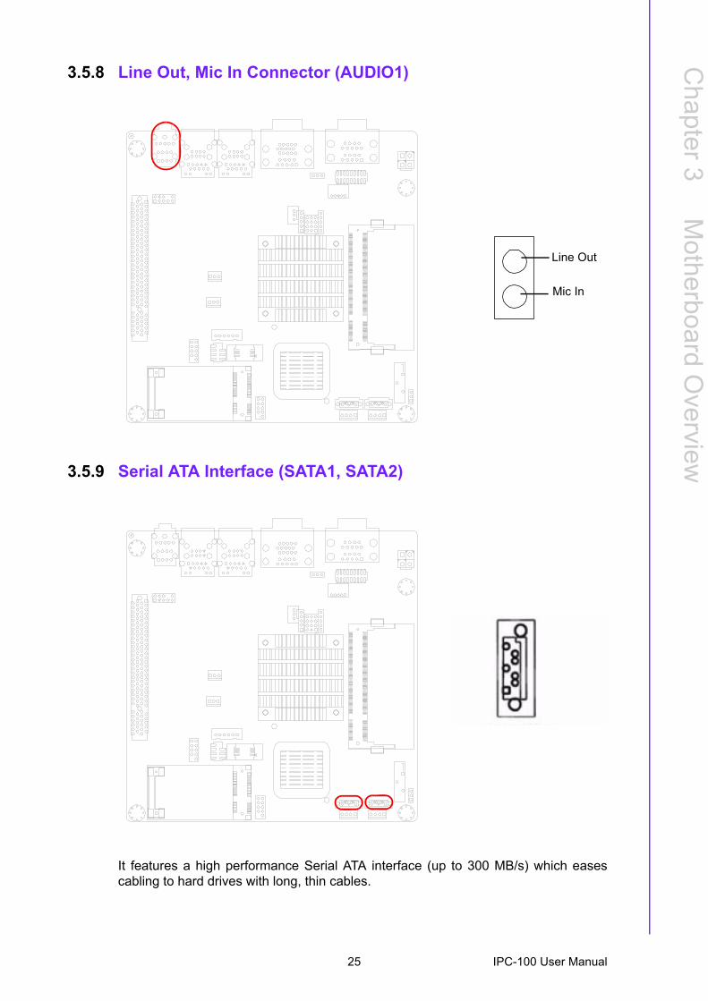
3.5.8 Line Out, Mic In Connector (AUDIO1)
3.5.9 Serial ATA Interface (SATA1, SATA2)
It features a high performance Serial ATA interface (up to 300 MB/s) which easescabling to hard drives with long, thin cables.
Line Out
Mic In
25 IPC-100 User Manual
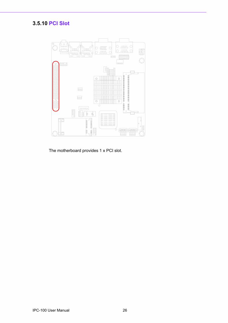
3.5.10 PCI Slot
The motherboard provides 1 x PCI slot.
IPC-100 User Manual 26
Chapter 3
Motherboard
Overview
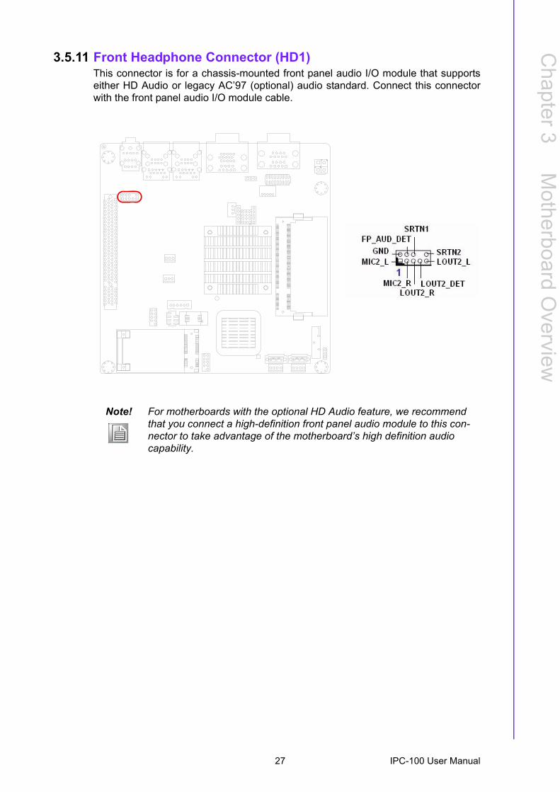
3.5.11 Front Headphone Connector (HD1)This connector is for a chassis-mounted front panel audio I/O module that supportseither HD Audio or legacy AC�97 (optional) audio standard. Connect this connectorwith the front panel audio I/O module cable.
Note! For motherboards with the optional HD Audio feature, we recommend that you connect a high-definition front panel audio module to this con-nector to take advantage of the motherboard�s high definition audio capability.
27 IPC-100 User Manual
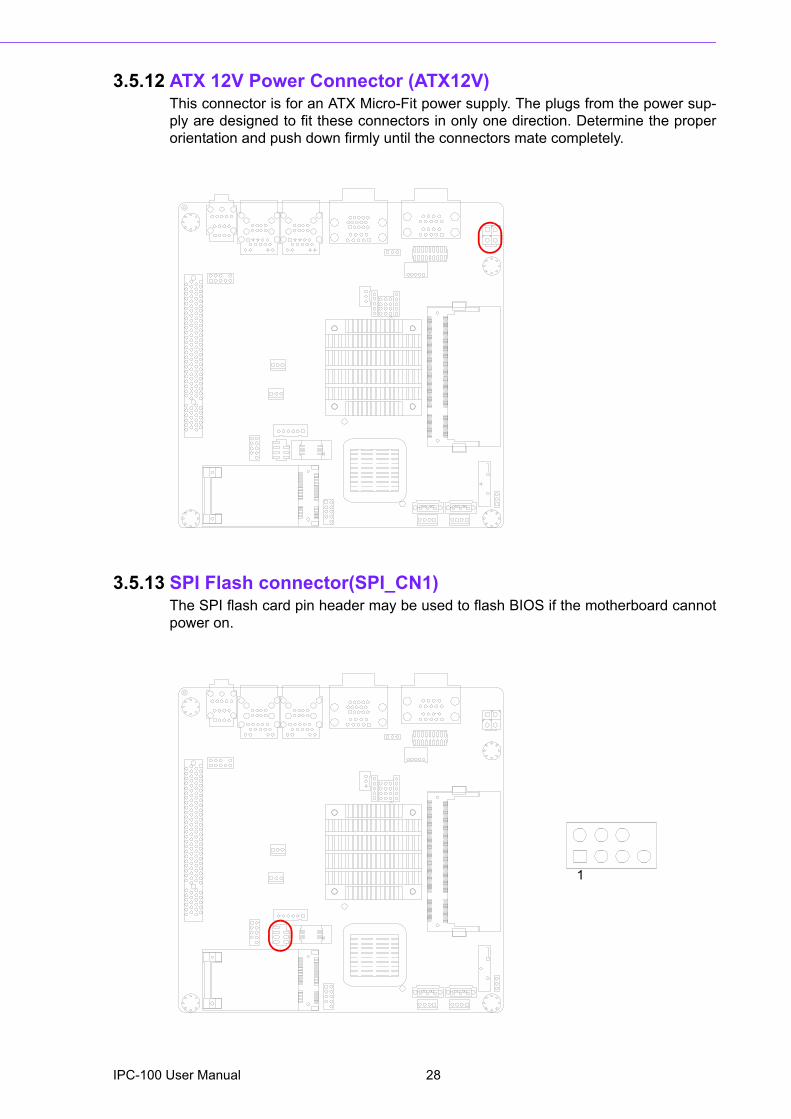
3.5.12 ATX 12V Power Connector (ATX12V)This connector is for an ATX Micro-Fit power supply. The plugs from the power sup-ply are designed to fit these connectors in only one direction. Determine the properorientation and push down firmly until the connectors mate completely.
3.5.13 SPI Flash connector(SPI_CN1)The SPI flash card pin header may be used to flash BIOS if the motherboard cannotpower on.
1
IPC-100 User Manual 28

Chapter 4
4 Operation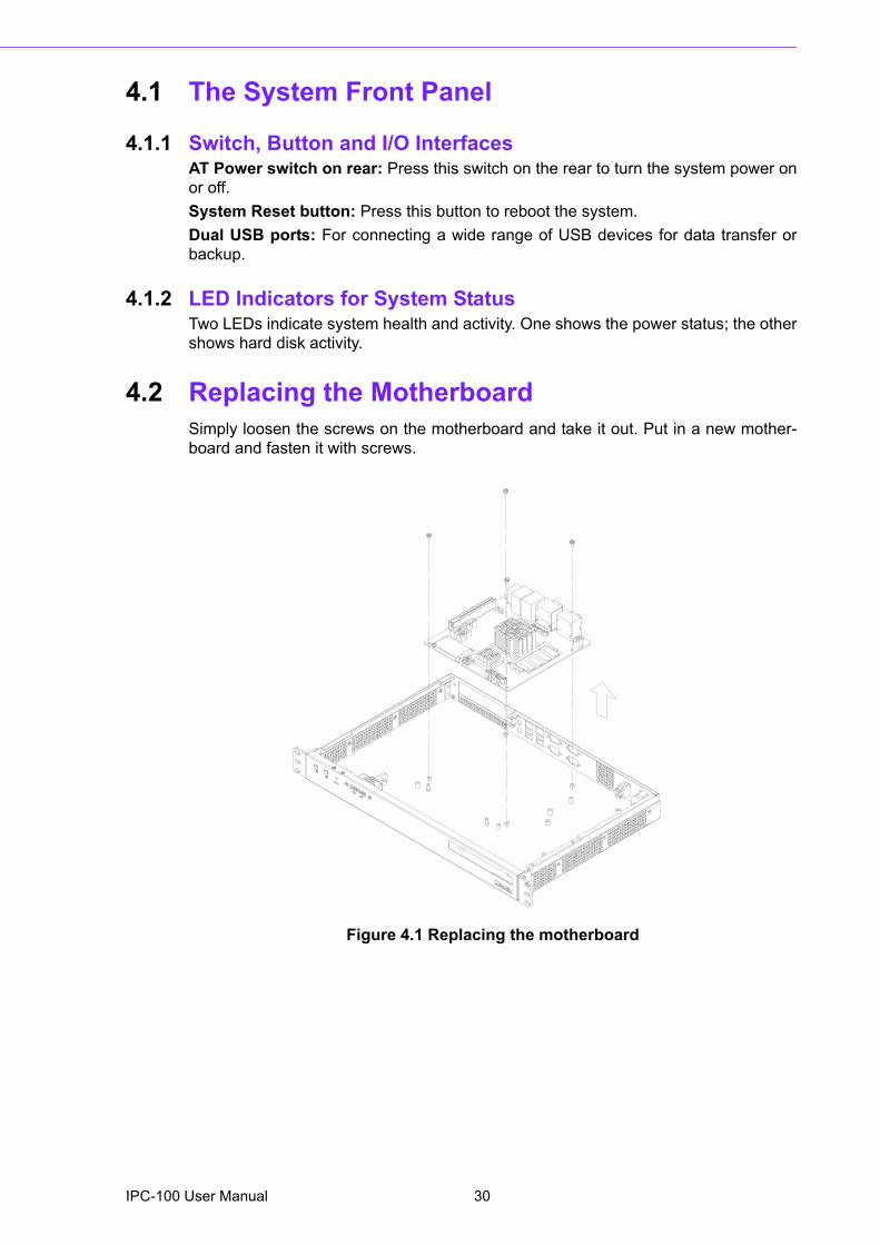
4.1 The System Front Panel
4.1.1 Switch, Button and I/O InterfacesAT Power switch on rear: Press this switch on the rear to turn the system power onor off. System Reset button: Press this button to reboot the system.Dual USB ports: For connecting a wide range of USB devices for data transfer orbackup.
4.1.2 LED Indicators for System StatusTwo LEDs indicate system health and activity. One shows the power status; the othershows hard disk activity.
4.2 Replacing the MotherboardSimply loosen the screws on the motherboard and take it out. Put in a new mother-board and fasten it with screws.
Figure 4.1 Replacing the motherboard
IPC-100 User Manual 30
Chapter 4
Operation
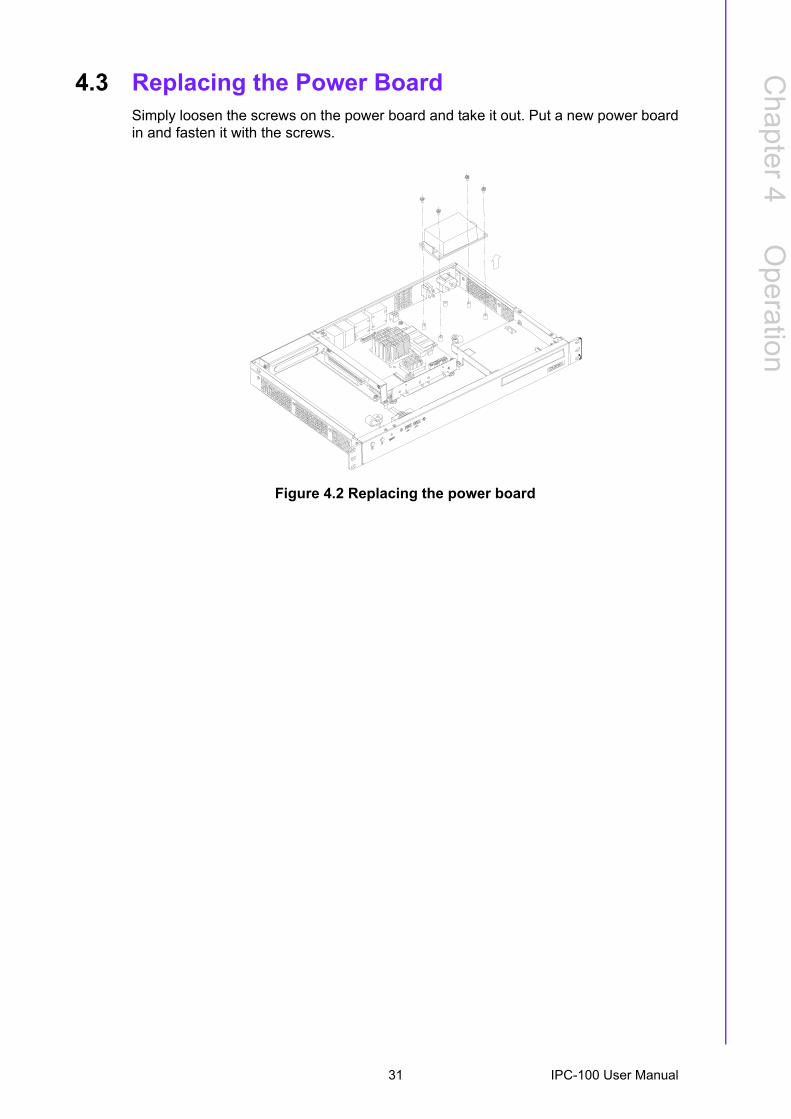
4.3 Replacing the Power BoardSimply loosen the screws on the power board and take it out. Put a new power boardin and fasten it with the screws.
Figure 4.2 Replacing the power board
31 IPC-100 User Manual

IPC-100 User Manual 32
Chapter 5
5 BIOS Operation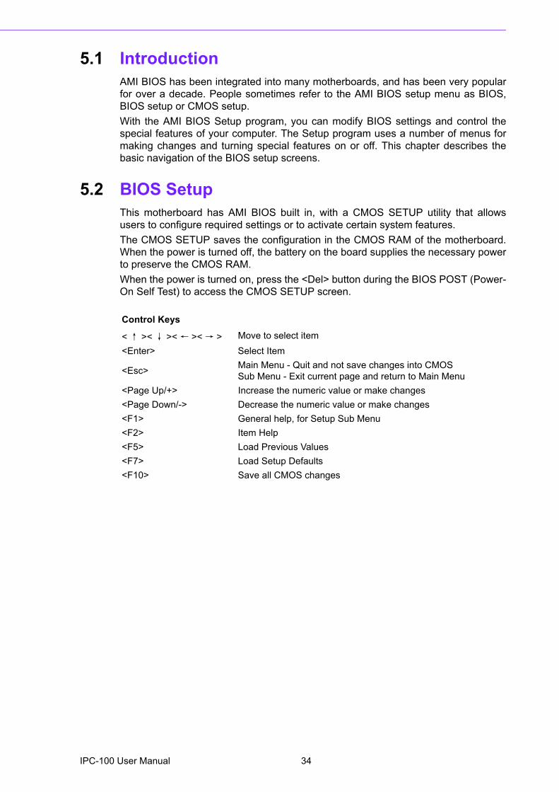
5.1 IntroductionAMI BIOS has been integrated into many motherboards, and has been very popularfor over a decade. People sometimes refer to the AMI BIOS setup menu as BIOS,BIOS setup or CMOS setup.With the AMI BIOS Setup program, you can modify BIOS settings and control thespecial features of your computer. The Setup program uses a number of menus formaking changes and turning special features on or off. This chapter describes thebasic navigation of the BIOS setup screens.
5.2 BIOS SetupThis motherboard has AMI BIOS built in, with a CMOS SETUP utility that allowsusers to configure required settings or to activate certain system features.The CMOS SETUP saves the configuration in the CMOS RAM of the motherboard.When the power is turned off, the battery on the board supplies the necessary powerto preserve the CMOS RAM.When the power is turned on, press the <Del> button during the BIOS POST (Power-On Self Test) to access the CMOS SETUP screen.
Control Keys
<↑ ><↓ ><← ><→ > Move to select item<Enter> Select Item
<Esc> Main Menu - Quit and not save changes into CMOSSub Menu - Exit current page and return to Main Menu
<Page Up/+> Increase the numeric value or make changes<Page Down/-> Decrease the numeric value or make changes<F1> General help, for Setup Sub Menu<F2> Item Help<F5> Load Previous Values<F7> Load Setup Defaults<F10> Save all CMOS changes
IPC-100 User Manual 34
Chapter 5
BIO
S O
peration
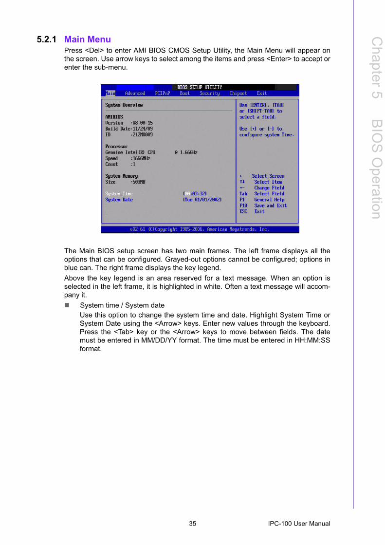
5.2.1 Main MenuPress <Del> to enter AMI BIOS CMOS Setup Utility, the Main Menu will appear onthe screen. Use arrow keys to select among the items and press <Enter> to accept orenter the sub-menu.
The Main BIOS setup screen has two main frames. The left frame displays all theoptions that can be configured. Grayed-out options cannot be configured; options inblue can. The right frame displays the key legend.Above the key legend is an area reserved for a text message. When an option isselected in the left frame, it is highlighted in white. Often a text message will accom-pany it.! System time / System date
Use this option to change the system time and date. Highlight System Time orSystem Date using the <Arrow> keys. Enter new values through the keyboard.Press the <Tab> key or the <Arrow> keys to move between fields. The datemust be entered in MM/DD/YY format. The time must be entered in HH:MM:SSformat.
35 IPC-100 User Manual
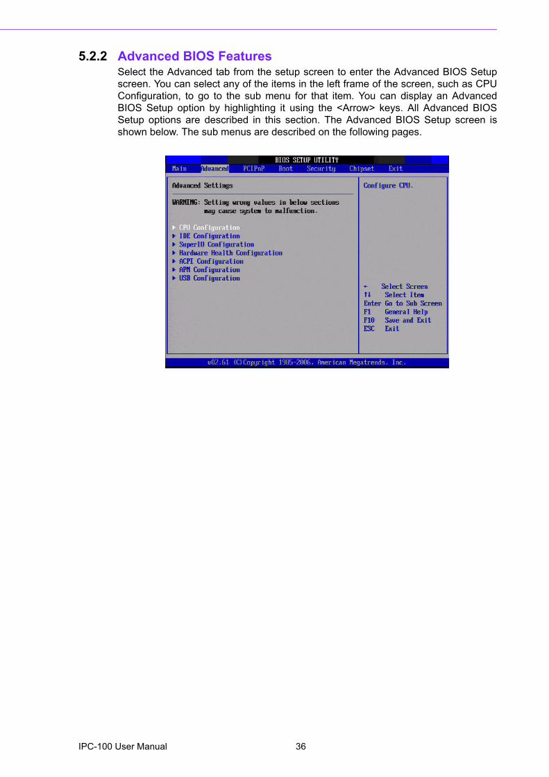
5.2.2 Advanced BIOS FeaturesSelect the Advanced tab from the setup screen to enter the Advanced BIOS Setupscreen. You can select any of the items in the left frame of the screen, such as CPUConfiguration, to go to the sub menu for that item. You can display an AdvancedBIOS Setup option by highlighting it using the <Arrow> keys. All Advanced BIOSSetup options are described in this section. The Advanced BIOS Setup screen isshown below. The sub menus are described on the following pages.
IPC-100 User Manual 36
Chapter 5
BIO
S O
peration
5.2.3 CPU Configuration
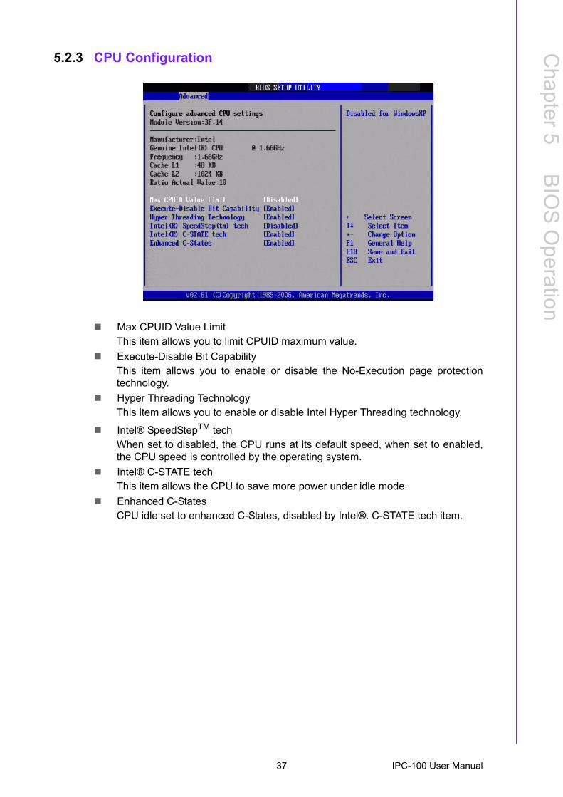
! Max CPUID Value LimitThis item allows you to limit CPUID maximum value.
! Execute-Disable Bit CapabilityThis item allows you to enable or disable the No-Execution page protectiontechnology.
! Hyper Threading TechnologyThis item allows you to enable or disable Intel Hyper Threading technology.
! Intel® SpeedStepTM techWhen set to disabled, the CPU runs at its default speed, when set to enabled,the CPU speed is controlled by the operating system.
! Intel® C-STATE techThis item allows the CPU to save more power under idle mode.
! Enhanced C-StatesCPU idle set to enhanced C-States, disabled by Intel®. C-STATE tech item.
37 IPC-100 User Manual
5.2.4 IDE Configuration
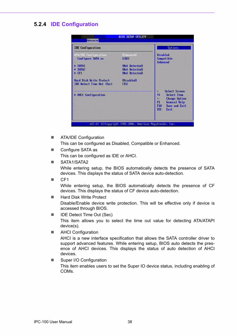
! ATA/IDE ConfigurationThis can be configured as Disabled, Compatible or Enhanced.
! Configure SATA asThis can be configured as IDE or AHCI.
! SATA1/SATA2While entering setup, the BIOS automatically detects the presence of SATAdevices. This displays the status of SATA device auto-detection.
! CF1While entering setup, the BIOS automatically detects the presence of CFdevices. This displays the status of CF device auto-detection.
! Hard Disk Write ProtectDisable/Enable device write protection. This will be effective only if device isaccessed through BIOS.
! IDE Detect Time Out (Sec)This item allows you to select the time out value for detecting ATA/ATAPIdevice(s).
! AHCI ConfigurationAHCI is a new interface specification that allows the SATA controller driver tosupport advanced features. While entering setup, BIOS auto detects the pres-ence of AHCI devices. This displays the status of auto detection of AHCIdevices.
! Super I/O ConfigurationThis item enables users to set the Super IO device status, including enabling ofCOMs.
IPC-100 User Manual 38
Chapter 5
BIO
S O
peration
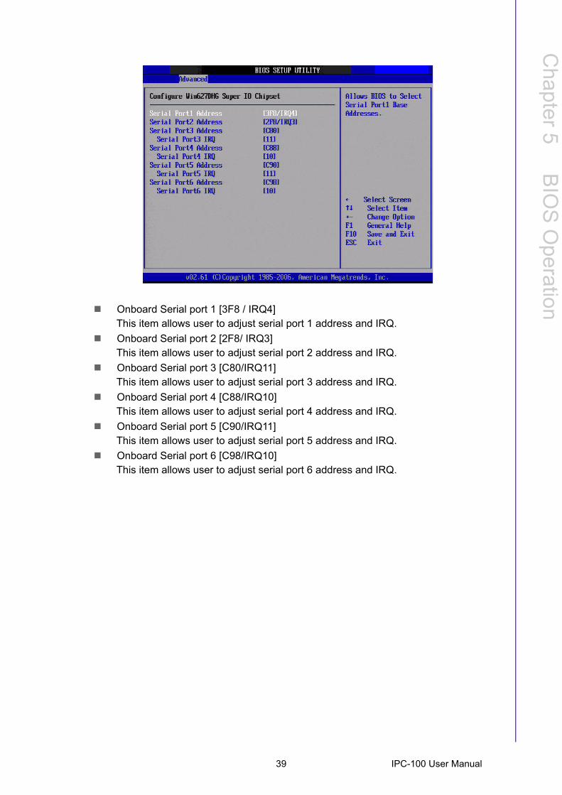
! Onboard Serial port 1 [3F8 / IRQ4]This item allows user to adjust serial port 1 address and IRQ.! Onboard Serial port 2 [2F8/ IRQ3]This item allows user to adjust serial port 2 address and IRQ.
! Onboard Serial port 3 [C80/IRQ11]This item allows user to adjust serial port 3 address and IRQ.
! Onboard Serial port 4 [C88/IRQ10]This item allows user to adjust serial port 4 address and IRQ.
! Onboard Serial port 5 [C90/IRQ11]This item allows user to adjust serial port 5 address and IRQ.
! Onboard Serial port 6 [C98/IRQ10]This item allows user to adjust serial port 6 address and IRQ.
39 IPC-100 User Manual
5.2.5 Hardware Health Configuration
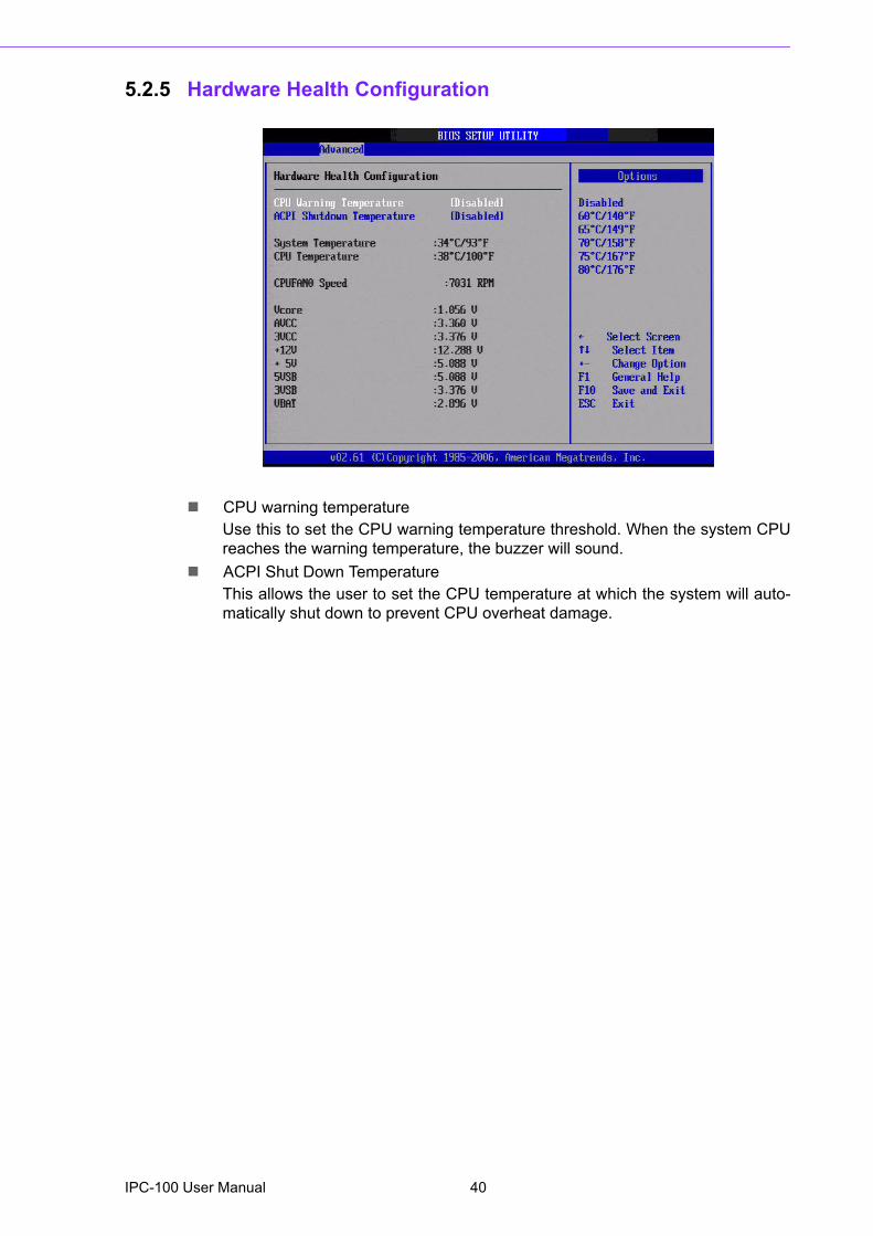
! CPU warning temperatureUse this to set the CPU warning temperature threshold. When the system CPUreaches the warning temperature, the buzzer will sound.
! ACPI Shut Down TemperatureThis allows the user to set the CPU temperature at which the system will auto-matically shut down to prevent CPU overheat damage.
IPC-100 User Manual 40
Chapter 5
BIO
S O
peration
5.2.6 ACPI Setting
5.2.7 General ACPI Configuration
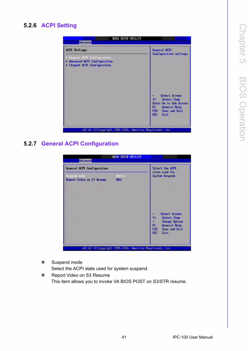
! Suspend modeSelect the ACPI state used for system suspend.
! Report Video on S3 ResumeThis item allows you to invoke VA BIOS POST on S3/STR resume.
41 IPC-100 User Manual
5.2.8 Advanced ACPI Configuration
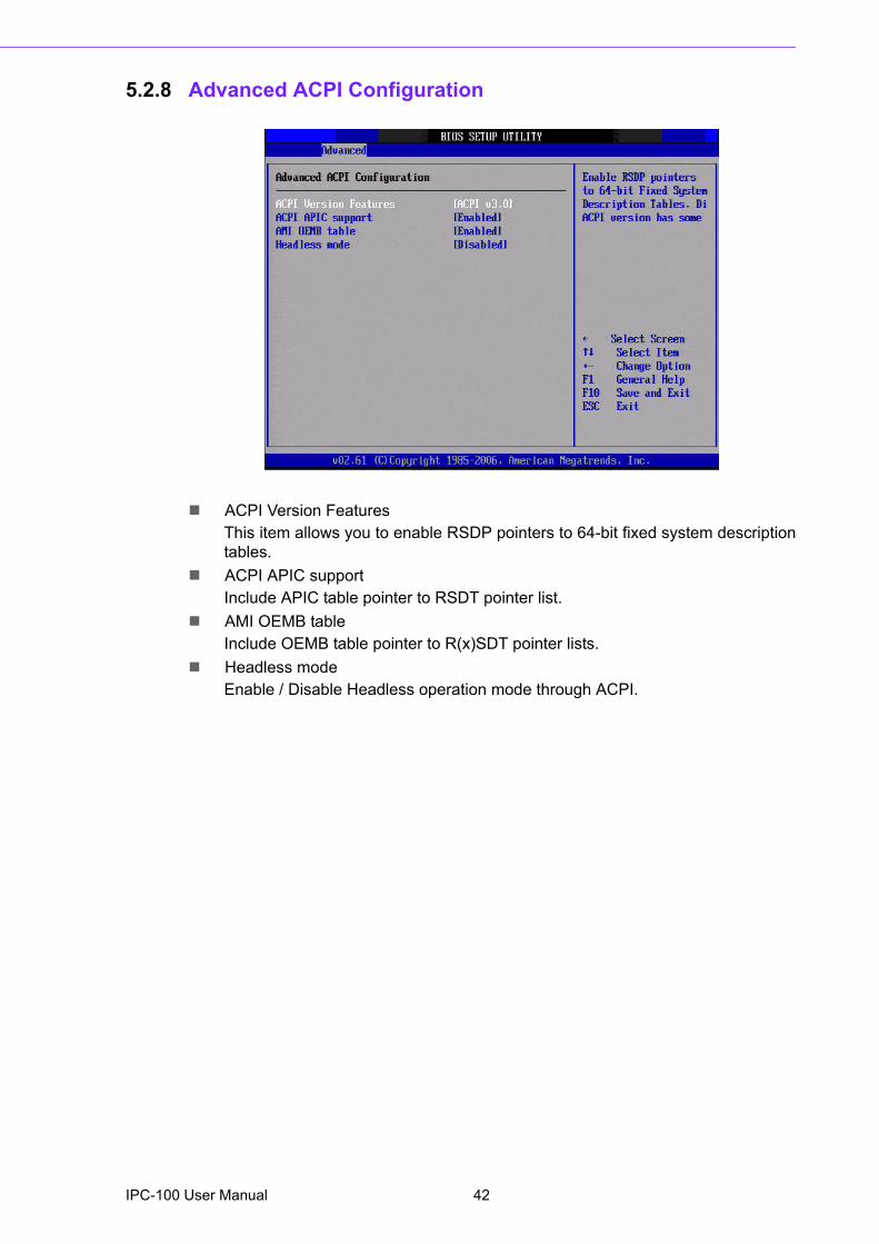
! ACPI Version FeaturesThis item allows you to enable RSDP pointers to 64-bit fixed system descriptiontables.
! ACPI APIC supportInclude APIC table pointer to RSDT pointer list.
! AMI OEMB tableInclude OEMB table pointer to R(x)SDT pointer lists.
! Headless modeEnable / Disable Headless operation mode through ACPI.
IPC-100 User Manual 42
Chapter 5
BIO
S O
peration
5.2.9 Chipset ACPI Configuration
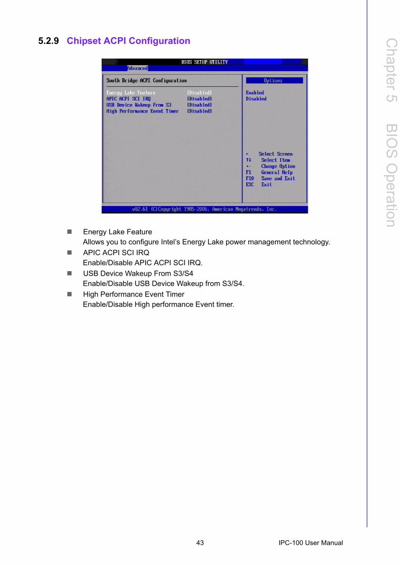
! Energy Lake FeatureAllows you to configure Intel�s Energy Lake power management technology.
! APIC ACPI SCI IRQEnable/Disable APIC ACPI SCI IRQ.
! USB Device Wakeup From S3/S4Enable/Disable USB Device Wakeup from S3/S4.
! High Performance Event TimerEnable/Disable High performance Event timer.
43 IPC-100 User Manual
5.2.10 APM Configuration
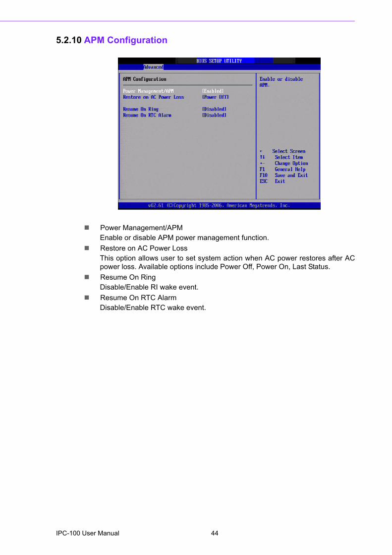
! Power Management/APMEnable or disable APM power management function.
! Restore on AC Power LossThis option allows user to set system action when AC power restores after ACpower loss. Available options include Power Off, Power On, Last Status.
! Resume On RingDisable/Enable RI wake event.
! Resume On RTC AlarmDisable/Enable RTC wake event.
IPC-100 User Manual 44
Chapter 5
BIO
S O
peration
5.2.11 USB Configuration
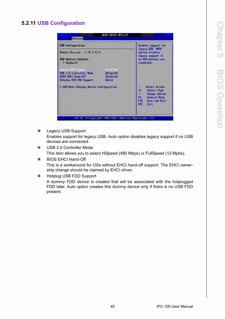
! Legacy USB SupportEnables support for legacy USB. Auto option disables legacy support if no USBdevices are connected.
! USB 2.0 Controller ModeThis item allows you to select HiSpeed (480 Mbps) or FullSpeed (12 Mpbs).
! BIOS EHCI Hand-OffThis is a workaround for OSs without EHCI hand-off support. The EHCI owner-ship change should be claimed by EHCI driver.
! Hotplug USB FDD SupportA dummy FDD device is created that will be associated with the hotpluggedFDD later. Auto option creates this dummy device only if there is no USB FDDpresent.
45 IPC-100 User Manual
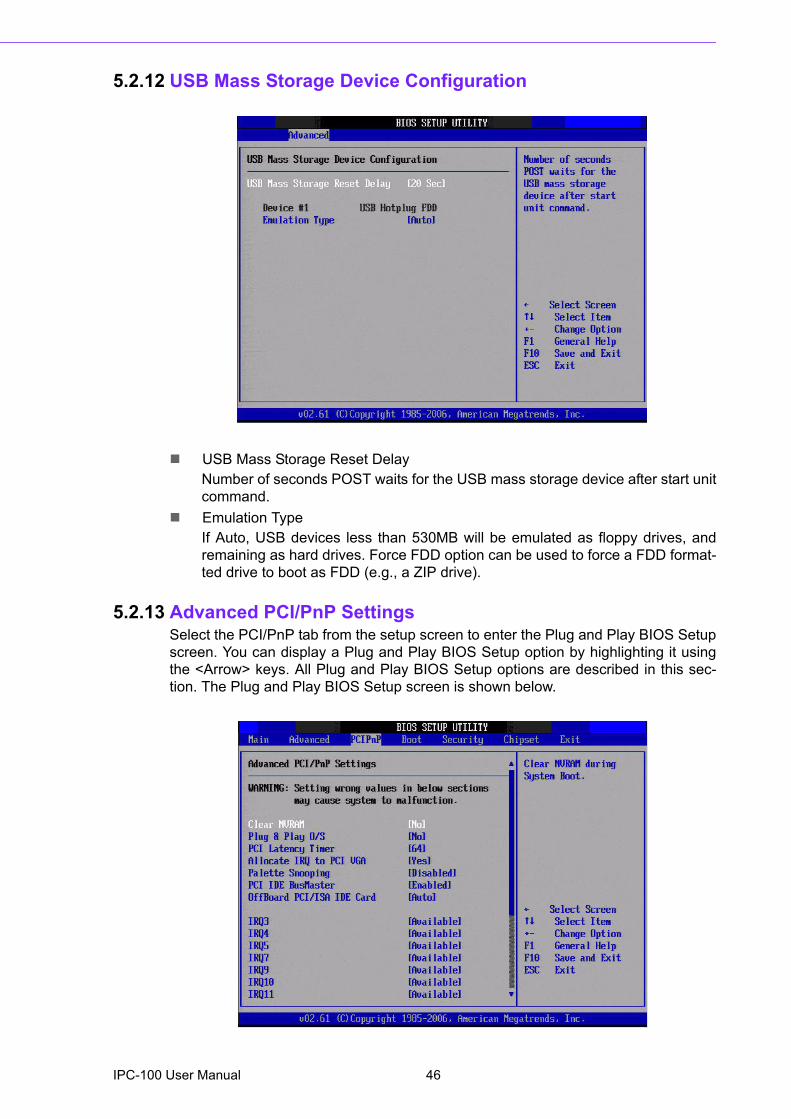
5.2.12 USB Mass Storage Device Configuration
! USB Mass Storage Reset DelayNumber of seconds POST waits for the USB mass storage device after start unitcommand.
! Emulation TypeIf Auto, USB devices less than 530MB will be emulated as floppy drives, andremaining as hard drives. Force FDD option can be used to force a FDD format-ted drive to boot as FDD (e.g., a ZIP drive).
5.2.13 Advanced PCI/PnP SettingsSelect the PCI/PnP tab from the setup screen to enter the Plug and Play BIOS Setupscreen. You can display a Plug and Play BIOS Setup option by highlighting it usingthe <Arrow> keys. All Plug and Play BIOS Setup options are described in this sec-tion. The Plug and Play BIOS Setup screen is shown below.
IPC-100 User Manual 46
Chapter 5
BIO
S O
peration
! Clear NVRAMSet this value to force the BIOS to clear the Non-Volatile Random Access Mem-ory (NVRAM).The Optimal and Fail-Safe default setting is No.
! Plug & Play O/SWhen set to No, BIOS configures all the devices in the system. When set to Yesand if you install a Plug and Play operating system, the operating system config-ures the Plug and Play devices not required for bootup.
! PCI Latency TimerValue in units of PCI clocks for PCI device latency timer register.
! Allocate IRQ to PCI VGAWhen set to Yes, will assign IRQ to PCI VGA card if card requests IRQ. Whenset to No will not assign IRQ to PCI VGA card even if card requests an IRQ.
! Palette SnoopingThis item is designed to solve problems caused by some non-standard VGAcard.
! PCI IDE BusMasterWhen set to enabled, BIOS uses PCI busmastering for reading/writing to IDEdrives.
! OffBoard PCI/ISA IDE CardSome PCI IDE cards may require this to be set to the PCI slot number that isholding the card. Set to Auto works for most PCI IDE cards.
! IRQ3 / 4 / 5 / 7 / 9 / 10 /11This item allows you respectively assign an interrupt types for IRQ-3, 4, 5, 7, 9,10, 11.
! DMA Channel0 / 1 / 3 / 5 / 6 / 7When set to Available, will specify DMA is available to be used by PCI/PnPdevices. When set to Reserved, will specified DMA is Reserved for use by leg-acy ISA devices.
! Reserved Memory SizeThis item allows you to reserve a set amount of memory for legacy ISA devices.
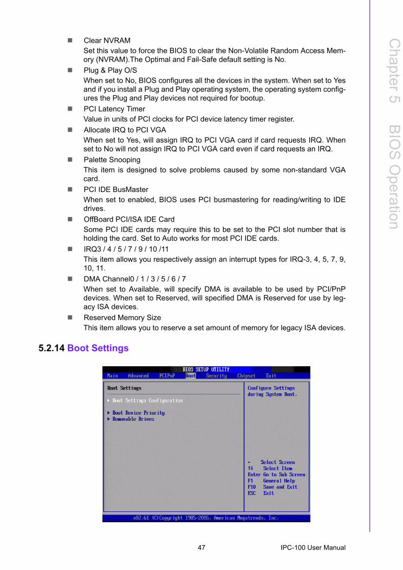
5.2.14 Boot Settings
47 IPC-100 User Manual
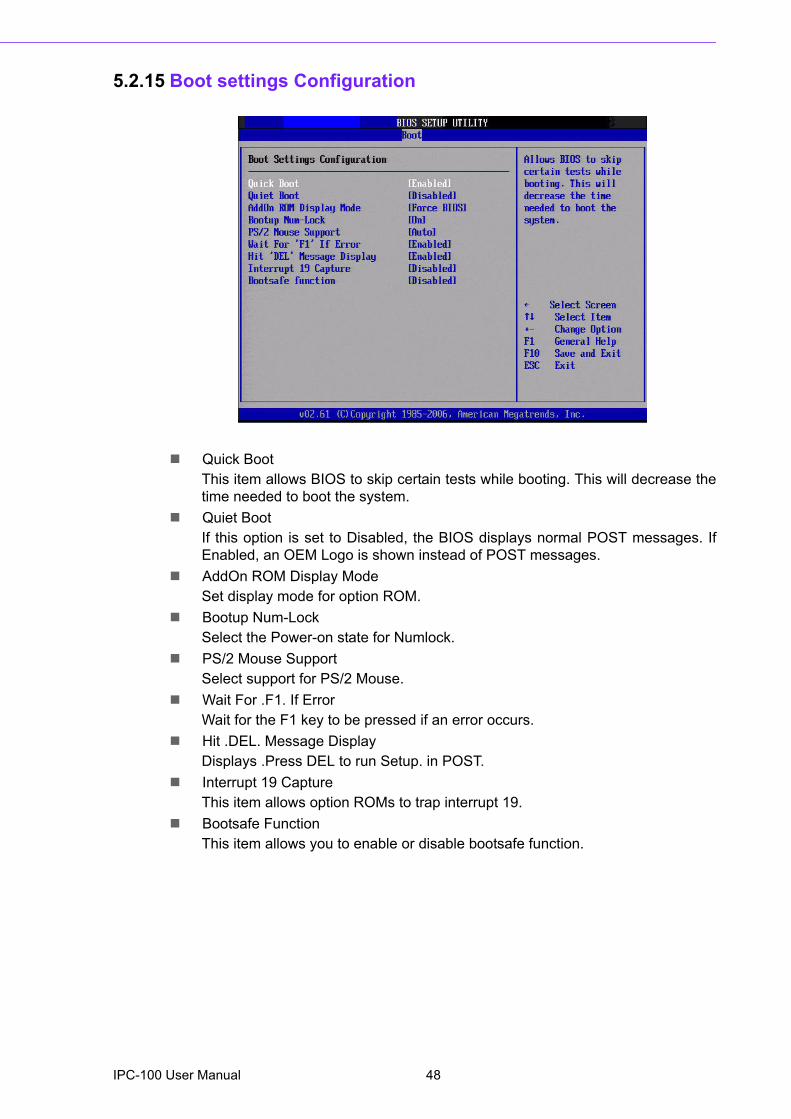
5.2.15 Boot settings Configuration
! Quick BootThis item allows BIOS to skip certain tests while booting. This will decrease thetime needed to boot the system.
! Quiet BootIf this option is set to Disabled, the BIOS displays normal POST messages. IfEnabled, an OEM Logo is shown instead of POST messages.
! AddOn ROM Display ModeSet display mode for option ROM.
! Bootup Num-LockSelect the Power-on state for Numlock.
! PS/2 Mouse SupportSelect support for PS/2 Mouse.
! Wait For .F1. If ErrorWait for the F1 key to be pressed if an error occurs.
! Hit .DEL. Message DisplayDisplays .Press DEL to run Setup. in POST.
! Interrupt 19 CaptureThis item allows option ROMs to trap interrupt 19.
! Bootsafe FunctionThis item allows you to enable or disable bootsafe function.
IPC-100 User Manual 48
Chapter 5
BIO
S O
peration
5.2.16 Security Setup
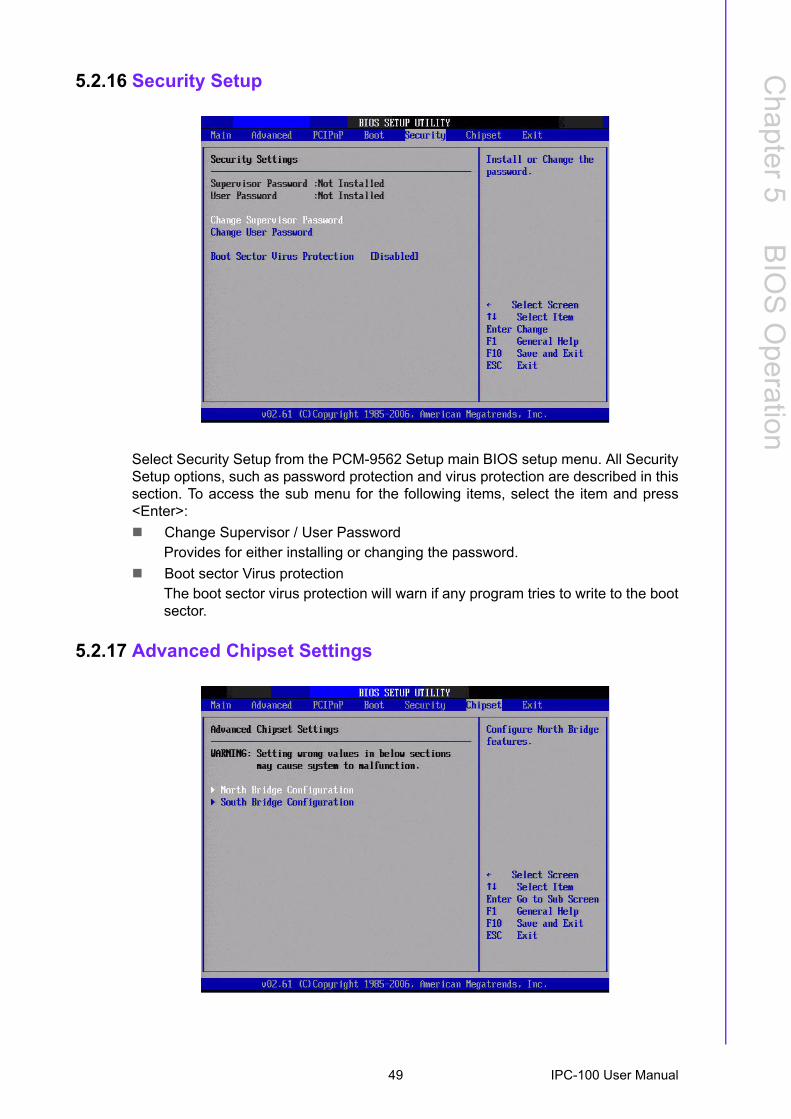
Select Security Setup from the PCM-9562 Setup main BIOS setup menu. All SecuritySetup options, such as password protection and virus protection are described in thissection. To access the sub menu for the following items, select the item and press<Enter>:! Change Supervisor / User Password
Provides for either installing or changing the password.! Boot sector Virus protection
The boot sector virus protection will warn if any program tries to write to the bootsector.
5.2.17 Advanced Chipset Settings
49 IPC-100 User Manual
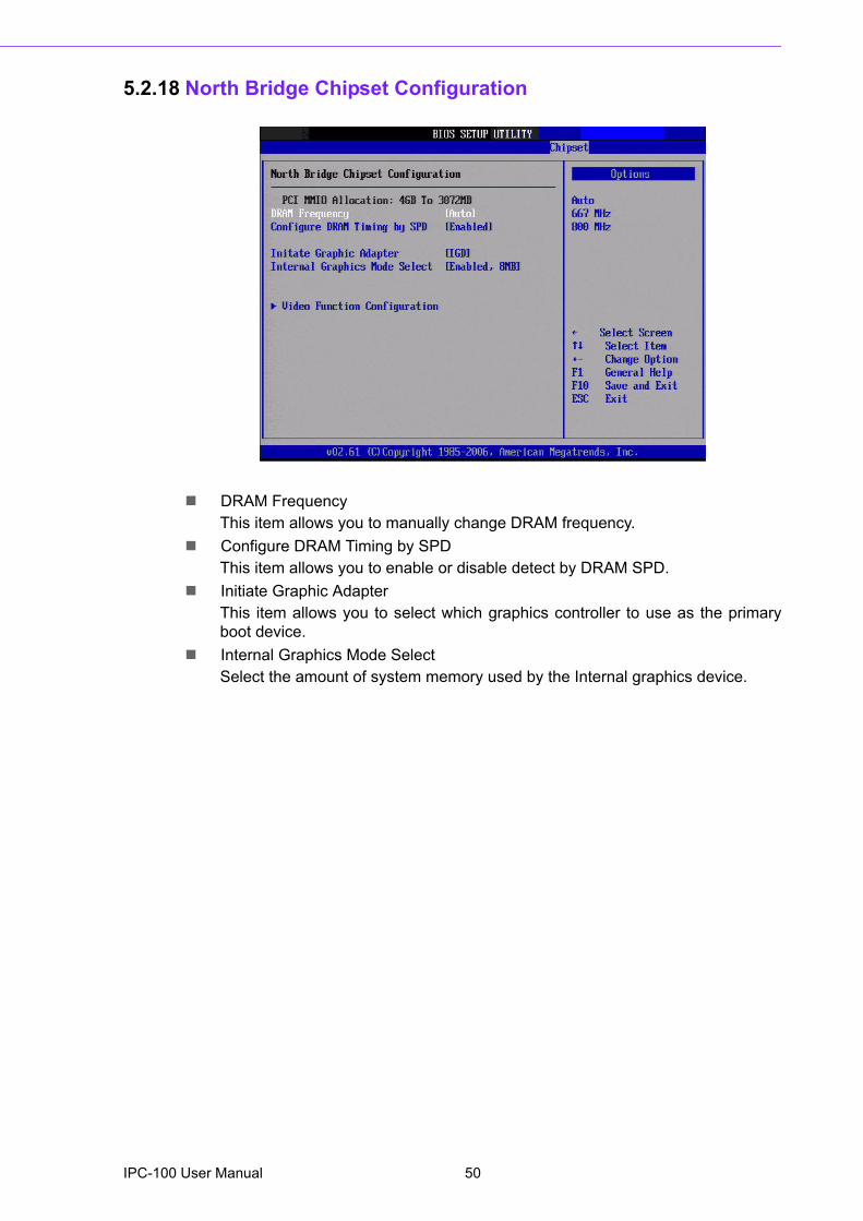
5.2.18 North Bridge Chipset Configuration
! DRAM FrequencyThis item allows you to manually change DRAM frequency.
! Configure DRAM Timing by SPDThis item allows you to enable or disable detect by DRAM SPD.
! Initiate Graphic AdapterThis item allows you to select which graphics controller to use as the primaryboot device.
! Internal Graphics Mode SelectSelect the amount of system memory used by the Internal graphics device.
IPC-100 User Manual 50
Chapter 5
BIO
S O
peration
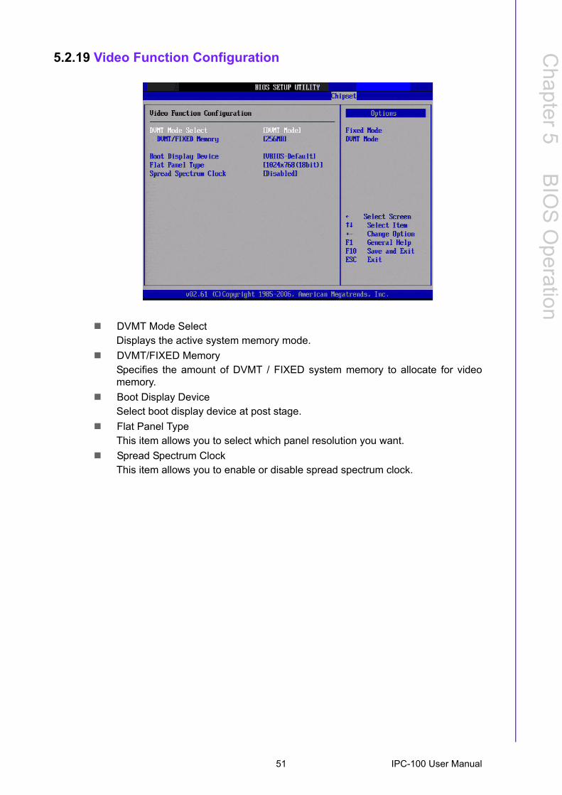
5.2.19 Video Function Configuration
! DVMT Mode SelectDisplays the active system memory mode.
! DVMT/FIXED MemorySpecifies the amount of DVMT / FIXED system memory to allocate for videomemory.
! Boot Display DeviceSelect boot display device at post stage.
! Flat Panel TypeThis item allows you to select which panel resolution you want.
! Spread Spectrum ClockThis item allows you to enable or disable spread spectrum clock.
51 IPC-100 User Manual

5.2.20 South Bridge Chipset Configuration
! USB FunctionsSelect: Disabled, 2 USB Ports, 4 USB Ports, 6 USB Ports or 8 USB Ports.
! USB 2.0 ControllerEnables or disables the USB 2.0 controller.
! LAN1 GbE controllerEnables or disables the GbE controller.
! LAN1 Option-ROMEnables or disables GbE LAN boot.
! Resume on LAN1Enables or disables GbE LAN wake up from S5 function.
! LAN2 GbE controllerEnables or disables the GbE controller.
! LAN2 Option-ROMEnables or disables GbE LAN boot.
! Resume on LAN2Enables or disables GbE LAN wake up from S5 function.
! HDA ControllerEnables or disables the HDA controller.
! SMBUS ControllerEnables or disables the SMBUS controller.
! SLP_S4# Min. Assertion WidthThis item allows you to set a delay of a set number of seconds.
IPC-100 User Manual 52
Chapter 5
BIO
S O
peration
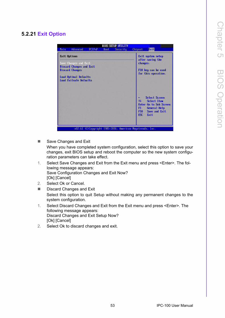
5.2.21 Exit Option
! Save Changes and ExitWhen you have completed system configuration, select this option to save yourchanges, exit BIOS setup and reboot the computer so the new system configu-ration parameters can take effect.
1. Select Save Changes and Exit from the Exit menu and press <Enter>. The fol-lowing message appears:Save Configuration Changes and Exit Now?[Ok] [Cancel]
2. Select Ok or Cancel.! Discard Changes and Exit
Select this option to quit Setup without making any permanent changes to thesystem configuration.
1. Select Discard Changes and Exit from the Exit menu and press <Enter>. The following message appears:Discard Changes and Exit Setup Now?[Ok] [Cancel]
2. Select Ok to discard changes and exit.
53 IPC-100 User Manual
! Discard Changes1. Select Discard Changes from the Exit menu and press <Enter>.! Load Optimal Defaults
The IPC-100 automatically configures all setup items to optimal settings whenyou select this option. Optimal Defaults are designed for maximum system per-formance, but may not work best for all computer applications. In particular, donot use the Optimal.Defaults if your computer is experiencing system configuration problems. SelectLoad Optimal Defaults from the Exit menu and press <Enter>.
! Load Failsafe DefaultsThe IPC-100 automatically configures all setup options to failsafe settings whenyou select this option. Failsafe Defaults are designed for maximum system sta-bility, but not maximum performance. Select Failsafe Defaults if your computeris experiencing system configuration problems.
1. Select Load Failsafe Defaults from the Exit menu and press <Enter>. The fol-lowing message appears:Load Failsafe Defaults?[OK] [Cancel]
2. Select OK to load Failsafe defaults.
IPC-100 User Manual 54

Chapter 6
6 Software Introduction & Service
6.1 IntroductionThe mission of Advantech Embedded Software Services is to "Enhance quality of lifewith Advantech platforms and Microsoft® Windows® embedded technology." Weenable Windows® Embedded software products on Advantech platforms to moreeffectively support the embedded computing community. Customers are freed fromthe hassle of dealing with multiple vendors (hardware suppliers, system integrators,embedded OS distributors) for projects. Our goal is to make Windows® EmbeddedSoftware solutions easily and widely available to the embedded computing commu-nity.
6.2 Value-Added Software ServicesSoftware API: An interface that defines the ways by which an application programmay request services from libraries and/or operating systems. Provides not only theunderlying drivers required but also a rich set of user-friendly, intelligent and inte-grated interfaces, which speeds development, enhances security and offers add-onvalue for Advantech platforms. It plays the role of catalyst between developer andsolution, and makes Advantech embedded platforms easier and simpler to adopt andoperate with customer applications.
6.2.1 Software API
6.2.1.1 Control
GPIOGeneral Purpose Input/Output is a flexible parallel interface that allows a variety of custom connections. Allows users to monitor the level of signal input or set the output status to switch on/off the device. Our API also provide Programmable GPIO, which allows developers to dynamically set the GPIO input or output status.
SMBusSMBus is the System Management Bus defined by Intel Cor-poration in 1995. It is used in personal computers and serv-ers for low-speed system management communications. The SMBus API allows a developer to interface a embedded sys-tem environment and transfer serial messages using the SMBus protocols, allowing multiple simultaneous device control.
IPC-100 User Manual 56
Chapter 6
Softw
areIntroduction
&S
ervice
6.2.1.2 Display
6.2.1.3 Monitor
6.2.1.4 Power Saving
Brightness ControlThe Brightness Control API allows a developer to access embedded devices and easily control brightness.
BacklightThe Backlight API allows a developer to control the backlight (screen) on/off in embedded devices.
WatchdogA watchdog timer (WDT) is a device that performs a specific operation after a certain period of time if something goes wrong and the system does not recover on its own. A watch-dog timer can be programmed to perform a warm boot (restarting the system) after a certain number of seconds.
Hardware MonitorThe Hardware Monitor (HWM) API is a system health super-vision API that inspects certain condition indexes, such as fan speed, temperature and voltage.
CPU SpeedMakes use of Intel SpeedStep technology to save power con-sumption. The system will automatically adjust the CPU speed depending on the system loading.
System ThrottlingRefers to a series of methods for reducing power consump-tion in computers by lowering the clock frequency. This API allows the user to adjust the clock from 87.5% to 12.5%.
57 IPC-100 User Manual
6.2.2 Software Utility
BIOS FlashThe BIOS Flash utility allows customers to update the flash ROM BIOS version, or use it to back up current BIOS by copying it from the flash chip to a file on customers� disk. The BIOS Flash utility also provides a command line version and an API for fast implementation into custom-ized applications.
Embedded Security IDThe embedded application is the most important property of a system integrator. It contains valuable intellectual property, design knowledge and innovation, but it is easy to be copied! Embedded Security ID utility which provides reliable security functions for customers to secure their application data within embedded BIOS.
MonitoringThe Monitoring is a utility for customer to monitor the sys-tem health, like voltage, CPU and system temperature and fan speed. These items are important to a device, if the critical errors occur and are not solved immediately, per-manent damage may be caused.
Flash LockFlash Lock is a mechanism to bind the Board and CF card (SQFlash) together. User can �Lock� SQFlash via Flash Lock function and �Unlock� by BIOS while booting. A locked SQFlash cannot be read by any card reader or boot from other platforms without a BIOS with �Unlock� feature.
eSOSThe eSOS is a small OS stored in BIOS ROM. It will boot up in case of a main OS crash. It will diagnose the hardware sta-tus, and then send an e-mail to the designated administrator. The eSOS also provide for remote connection via Telnet server and FTP server so the administrator can attempt to rescue the system. Note: This function requires BIOS cus-tomization.
IPC-100 User Manual 58
Chapter 7
7 Chipset Software Installation Utility
7.1 Before You BeginTo facilitate the installation of the enhanced display drivers and utility software, readthe instructions in this chapter carefully. The drivers for the motherboard are locatedon the software installation CD. The driver in the folder of the driver CD will guide andlink you to the utilities and drivers under a Windows system. Updates are providedvia Service Packs from Microsoft*.
Before you begin, it is important to note that most display drivers need to have therelevant software application already installed in the system prior to installing theenhanced display drivers. In addition, many of the installation procedures assumethat you are familiar with both the relevant software applications and operating sys-tem commands. Review the relevant operating system commands and the pertinentsections of your application software�s user manual before performing the installa-tion.
7.2 IntroductionThe Intel® Chipset Software Installation (CSI) utility installs the Windows INF filesthat outline to the operating system how the chipset components will be configured.This is needed for the proper functioning of the following features:! Core PCI PnP services! IDE Ultra ATA 100/66/33 and Serial ATA interface support! USB 1.1/2.0 support (USB 2.0 driver needs to be installed separately for Win98)! Identification of Intel® chipset components in the Device Manager! Integrates superior video features. These include filtered sealing of 720 pixel
DVD content, and MPEG-2 motion compensation for software DVD
Note! The files on the software installation CD are compressed. Do not attempt to install the drivers by copying the files manually. You must use the supplied SETUP program to install the drivers.
Note! This utility is used for the following versions of Windows, and it has to be installed before installing all the other drivers:! Windows 7! Windows Vista! Windows XP
IPC-100 User Manual 60
Chapter 7
ChipsetS
oftware
Installation Utility
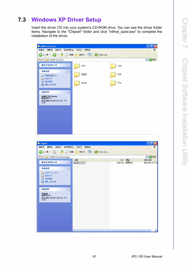
7.3 Windows XP Driver SetupInsert the driver CD into your system's CD-ROM drive. You can see the driver folderitems. Navigate to the "Chipset" folder and click "infinst_autol.exe" to complete theinstallation of the driver.
61 IPC-100 User Manual

IPC-100 User Manual 62

Chapter 8
8 VGA Setup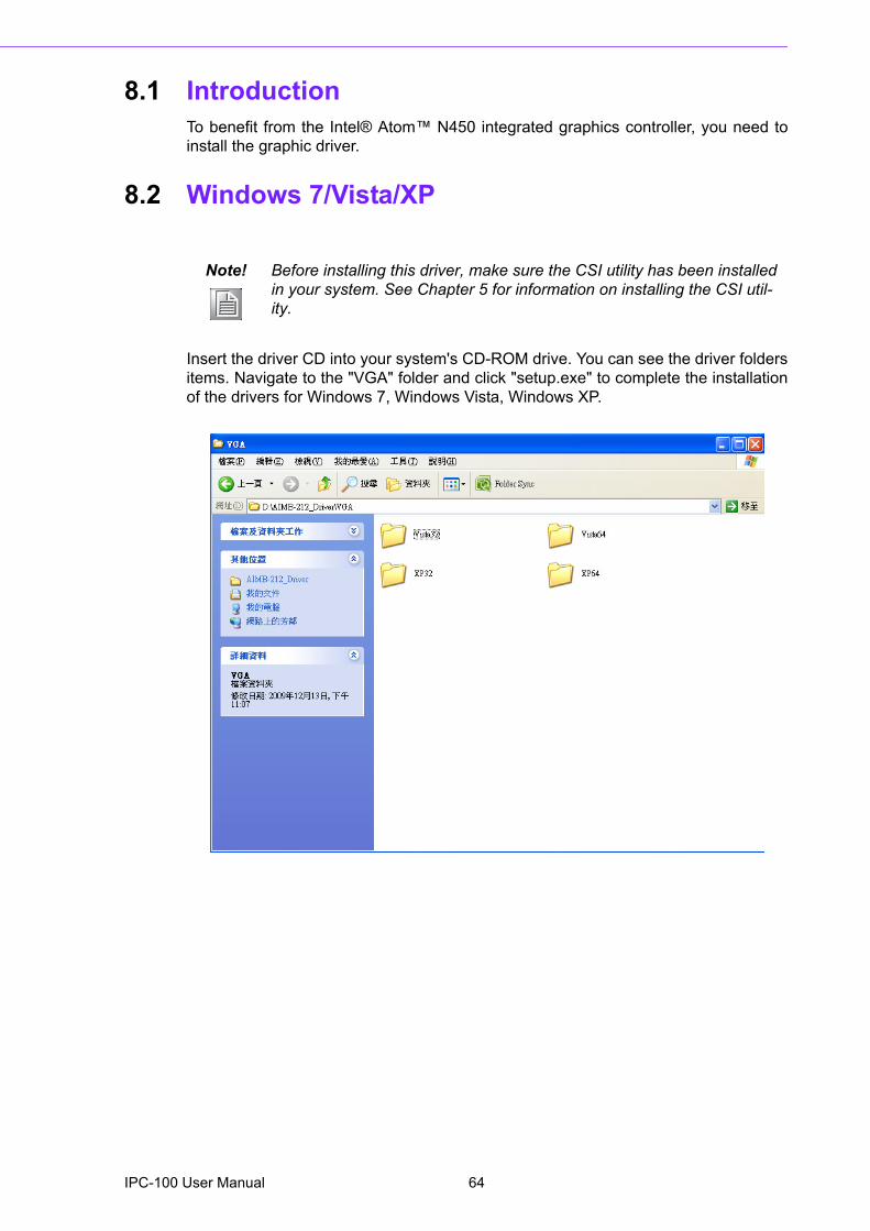
8.1 IntroductionTo benefit from the Intel® Atom� N450 integrated graphics controller, you need toinstall the graphic driver.
8.2 Windows 7/Vista/XP
Insert the driver CD into your system's CD-ROM drive. You can see the driver foldersitems. Navigate to the "VGA" folder and click "setup.exe" to complete the installationof the drivers for Windows 7, Windows Vista, Windows XP.
Note! Before installing this driver, make sure the CSI utility has been installed in your system. See Chapter 5 for information on installing the CSI util-ity.
IPC-100 User Manual 64

Chapter 9
9 LAN Configuration
9.1 IntroductionThe motherboard has dual Gigabit Ethernet LANs via dedicated PCI Express x1lanes (Intel 82567V (LAN1) and 82583V (LAN2)) that offer bandwidth of up to 500MB/sec, eliminating the bottleneck of network data flow and incorporating GigabitEthernet at 1000 Mbps.
9.2 Features! Integrated 10/100/1000 Mbps transceiver! 10/100/1000 Mbps triple-speed MAC! High-speed RISC core with 24-KB cache! On-chip voltage regulation! Wake-on-LAN (WOL) support! PCI Express X1 host interface
9.3 Installation
The Intel 82567V (LAN1) and 82583V (LAN2) Gigabit integrated controllers supportall major network operating systems. However, the installation procedure varies fromsystem to system. Please find and use the section that provides the driver setup pro-cedure for the operating system you are using.
Note! Before installing the LAN drivers, make sure the CSI utility has been installed on your system. See Chapter 5 for information on installing the CSI utility.
IPC-100 User Manual 66
Chapter 9
LAN
Configuration
9.4 Windows 7/Vista/XP Driver Setup (Intel 82567v/82583v)Insert the driver CD into the slim ODD. Select the LAN folder then navigate to thedirectory for your OS.
67 IPC-100 User Manual

IPC-100 User Manual 68

Appendix A
A Exploded Diagram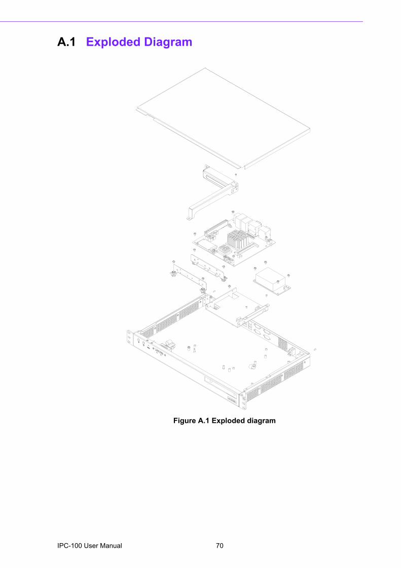
A.1 Exploded Diagram
Figure A.1 Exploded diagram
IPC-100 User Manual 70

Appendix B
B Programming the Watchdog Timer
B.1 Programming the Watchdog TimerThe IPC-100's watchdog timer can be used to monitor system software operationand take corrective action if the software fails to function within the programmedperiod. This section describes the operation of the watchdog timer and how to pro-gram it.
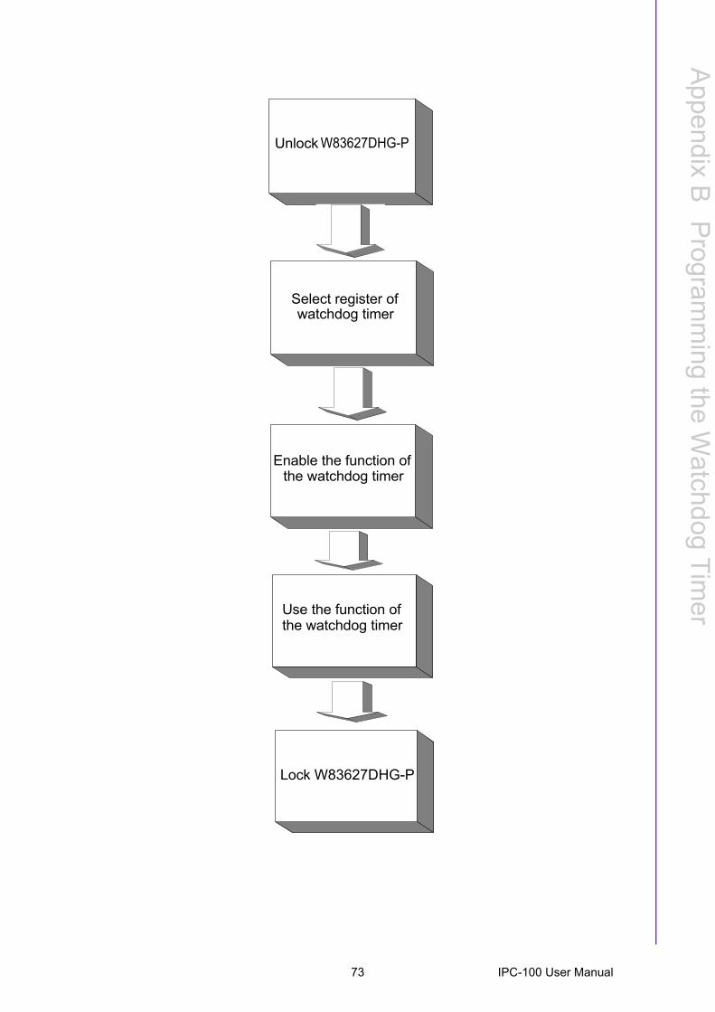
B.1.1 Watchdog Timer OverviewThe watchdog timer is built into the super I/O controller W83627DHG-P. It providesthe following user-programmable functions:! Can be enabled and disabled by user program! Timer can be set from 1 to 255 seconds or 1 to 255 minutes! Generates an interrupt or resets signal if the software fails to reset the timer
before time-out
B.1.2 Programming the Watchdog TimerThe I/O port address of the watchdog timer is 2E (hex) and 2F (hex). 2E (hex) is theaddress port. 2F (hex) is the data port. You must first assign the address of registerby writing an address value into address port 2E (hex), then write/read data to/fromthe assigned register through data port 2F (hex).
IPC-100 User Manual 72
Appendix B
Program
ming
theW
atchdogTim
er
Unlock
Select register of watchdog timer
Enable the function ofthe watchdog timer
Use the function of
Lock W83627DHG-P
the watchdog timer
W83627DHG-P
73 IPC-100 User Manual
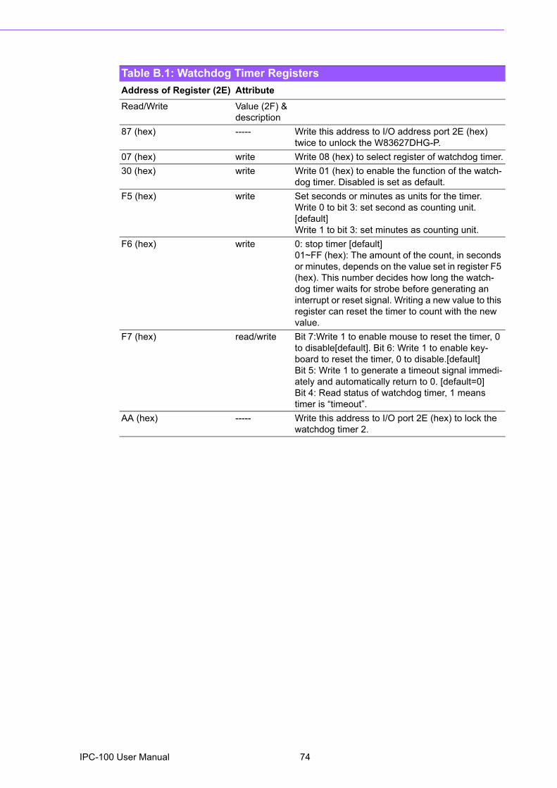
Table B.1: Watchdog Timer RegistersAddress of Register (2E) AttributeRead/Write Value (2F) &
description87 (hex) ----- Write this address to I/O address port 2E (hex)
twice to unlock the W83627DHG-P.07 (hex) write Write 08 (hex) to select register of watchdog timer.30 (hex) write Write 01 (hex) to enable the function of the watch-
dog timer. Disabled is set as default.F5 (hex) write Set seconds or minutes as units for the timer.
Write 0 to bit 3: set second as counting unit. [default]Write 1 to bit 3: set minutes as counting unit.
F6 (hex) write 0: stop timer [default]01~FF (hex): The amount of the count, in seconds or minutes, depends on the value set in register F5 (hex). This number decides how long the watch-dog timer waits for strobe before generating an interrupt or reset signal. Writing a new value to this register can reset the timer to count with the new value.
F7 (hex) read/write Bit 7:Write 1 to enable mouse to reset the timer, 0 to disable[default]. Bit 6: Write 1 to enable key-board to reset the timer, 0 to disable.[default] Bit 5: Write 1 to generate a timeout signal immedi-ately and automatically return to 0. [default=0]Bit 4: Read status of watchdog timer, 1 means timer is �timeout�.
AA (hex) ----- Write this address to I/O port 2E (hex) to lock the watchdog timer 2.
IPC-100 User Manual 74

Appendix B
Program
ming
theW
atchdogTim
er
B.1.3 Example Program1. Enable watchdog timer and set 10 sec. as timeout interval;-----------------------------------------------------------Mov dx,2eh ; Unlock W83627DHG-PMov al,87hOut dx,alOut dx,al;-----------------------------------------------------------Mov al,07h ; Select registers of watchdog timerOut dx,alInc dxMov al,08hOut dx,al;-----------------------------------------------------------Dec dx ; Enable the function of watchdog timerMov al,30hOut dx,alInc dxMov al,01hOut dx,al;-----------------------------------------------------------Dec dx ; Set second as counting unitMov al,0f5hOut dx,alInc dxIn al,dxAnd al,not 08hOut dx,al;-----------------------------------------------------------Dec dx ; Set timeout interval as 10 seconds and start countingMov al,0f6hOut dx,alInc dxMov al,10Out dx,al;-----------------------------------------------------------Dec dx ; Lock W83627DHG-PMov al,0aahOut dx,al2. Enable watchdog timer and set 5 minutes as timeout interval;-----------------------------------------------------------Mov dx,2eh ; Unlock W83627DHG-PMov al,87hOut dx,alOut dx,al
75 IPC-100 User Manual
;-----------------------------------------------------------Mov al,07h ; Select registers of watchdog timerOut dx,alInc dxMov al,08hOut dx,al;-----------------------------------------------------------Dec dx ; Enable the function of watchdog timerMov al,30hOut dx,alInc dxMov al,01hOut dx,al;-----------------------------------------------------------Dec dx ; Set minute as counting unitMov al,0f5hOut dx,alInc dxIn al,dxOr al,08hOut dx,al;-----------------------------------------------------------Dec dx ; Set timeout interval as 5 minutes and start countingMov al,0f6hOut dx,alInc dxMov al,5Out dx,al;-----------------------------------------------------------Dec dx ; Lock W83627DHG-PMov al,0aahOut dx,al3. Enable watchdog timer to be reset by mouse;-----------------------------------------------------------Mov dx,2eh ; Unlock W83627DHG-PMov al,87hOut dx,alOut dx,al;-----------------------------------------------------------Mov al,07h ; Select registers of watchdog timerOut dx,alInc dxMov al,08hOut dx,al;-----------------------------------------------------------
IPC-100 User Manual 76

Appendix B
Program
ming
theW
atchdogTim
er
Dec dx ; Enable the function of watchdog timerMov al,30hOut dx,alInc dxMov al,01hOut dx,al;-----------------------------------------------------------Dec dx ; Enable watchdog timer to be reset by mouseMov al,0f7hOut dx,alInc dxIn al,dxOr al,80hOut dx,al;-----------------------------------------------------------Dec dx ; Lock W83627DHG-PMov al,0aahOut dx,al4. Enable watchdog timer to be reset by keyboard;-----------------------------------------------------------Mov dx,2eh ; Unlock W83627DHG-PMov al,87hOut dx,alOut dx,al;-----------------------------------------------------------Mov al,07h ; Select registers of watchdog timerOut dx,alInc dxMov al,08hOut dx,al;-----------------------------------------------------------Dec dx ; Enable the function of watchdog timerMov al,30hOut dx,alInc dxMov al,01hOut dx,al;-----------------------------------------------------------Dec dx ; Enable watchdog timer to be strobed reset by keyboardMov al,0f7hOut dx,alInc dxIn al,dxOr al,40hOut dx,al
77 IPC-100 User Manual
;-----------------------------------------------------------Dec dx ; Lock W83627DHG-PMov al,0aahOut dx,al5. Generate a time-out signal without timer counting;-----------------------------------------------------------Mov dx,2eh ; Unlock W83627DHG-PMov al,87hOut dx,alOut dx,al;-----------------------------------------------------------Mov al,07h ; Select registers of watchdog timerOut dx,alInc dxMov al,08hOut dx,al;-----------------------------------------------------------Dec dx ; Enable the function of watchdog timerMov al,30hOut dx,alInc dxMov al,01hOut dx,al;-----------------------------------------------------------Dec dx ; Generate a time-out signalMov al,0f7hOut dx,al ;Write 1 to bit 5 of F7 registerInc dxIn al,dxOr al,20hOut dx,al;-----------------------------------------------------------Dec dx ; Lock W83627DHG-PMov al,0aahOut dx,al
IPC-100 User Manual 78

Appendix C
C I/O Pin Assignments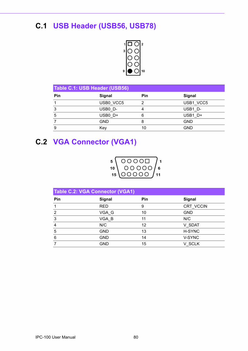
C.1 USB Header (USB56, USB78)
C.2 VGA Connector (VGA1)
Table C.1: USB Header (USB56)Pin Signal Pin Signal1 USB0_VCC5 2 USB1_VCC53 USB0_D- 4 USB1_D-5 USB0_D+ 6 USB1_D+7 GND 8 GND9 Key 10 GND
Table C.2: VGA Connector (VGA1)Pin Signal Pin Signal1 RED 9 CRT_VCCIN2 VGA_G 10 GND3 VGA_B 11 N/C4 N/C 12 V_SDAT5 GND 13 H-SYNC6 GND 14 V-SYNC7 GND 15 V_SCLK
5
15
1
1110 6
IPC-100 User Manual 80
Appendix C
I/O P
inA
ssignments
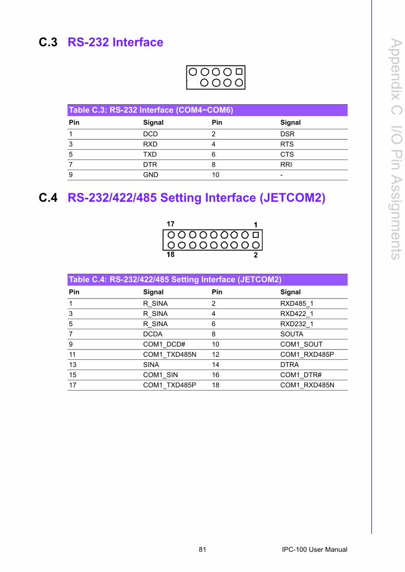
C.3 RS-232 Interface
C.4 RS-232/422/485 Setting Interface (JETCOM2)
Table C.3: RS-232 Interface (COM4~COM6)Pin Signal Pin Signal1 DCD 2 DSR3 RXD 4 RTS5 TXD 6 CTS7 DTR 8 RRI9 GND 10 -
Table C.4: RS-232/422/485 Setting Interface (JETCOM2)Pin Signal Pin Signal1 R_SINA 2 RXD485_13 R_SINA 4 RXD422_15 R_SINA 6 RXD232_17 DCDA 8 SOUTA9 COM1_DCD# 10 COM1_SOUT11 COM1_TXD485N 12 COM1_RXD485P13 SINA 14 DTRA15 COM1_SIN 16 COM1_DTR#17 COM1_TXD485P 18 COM1_RXD485N
81 IPC-100 User Manual
C.5 SPI_CN1: SPI Fresh Card Pin Connector
C.6 PS/2 Keyboard and Mouse Connector (KBMS1)
C.7 CPU Fan Power Connector (CPU_FAN1)
Table C.5: SPI_CN1:SPI Fresh Card Pin ConnectorPin Signal Pin Signal1 +F1_3V 2 GND3 F1_SPI_CS#_Q 4 F1_SPI_CLK_Q5 F1_SPI_MISO_Q 6 F1_SPI_MOSI_Q7 NC 8 NC
1 2
87
Table C.6: PS/2 Keyboard and Mouse Connector (KBMS1)Pin Signal1 KCLK_B2 KDAT_B3 MDAT_B4 GND5 KBMS1_VCC6 MCLK_B
5 4 23 16
Table C.7: CPU Fan Power Connector (CPU_FAN1)Pin Signal1 GND2 +12 V3 DETECT
1
2
3
IPC-100 User Manual 82
Appendix C
I/O P
inA
ssignments
C.8 System Fan Power Connector (CHA_FAN1)
C.9 Power LED & Keyboard Lock Connector (JFP1)You can use an LED to indicate when the single board computer is on. Pin 1 of JFP3supplies the LED's power, and Pin 3 is the ground.
Table C.8: System Fan Power Connector (SYSFAN1/SYSFAN2)Pin Signal1 GND2 +12 V3 DETECT
1
2
3
Table C.9: Power LED & Keyboard Lock Connector (JFP1)Pin Function 1 LED power2 NC 3 GND 4 KEYLOCK# 5 GND
83 IPC-100 User Manual
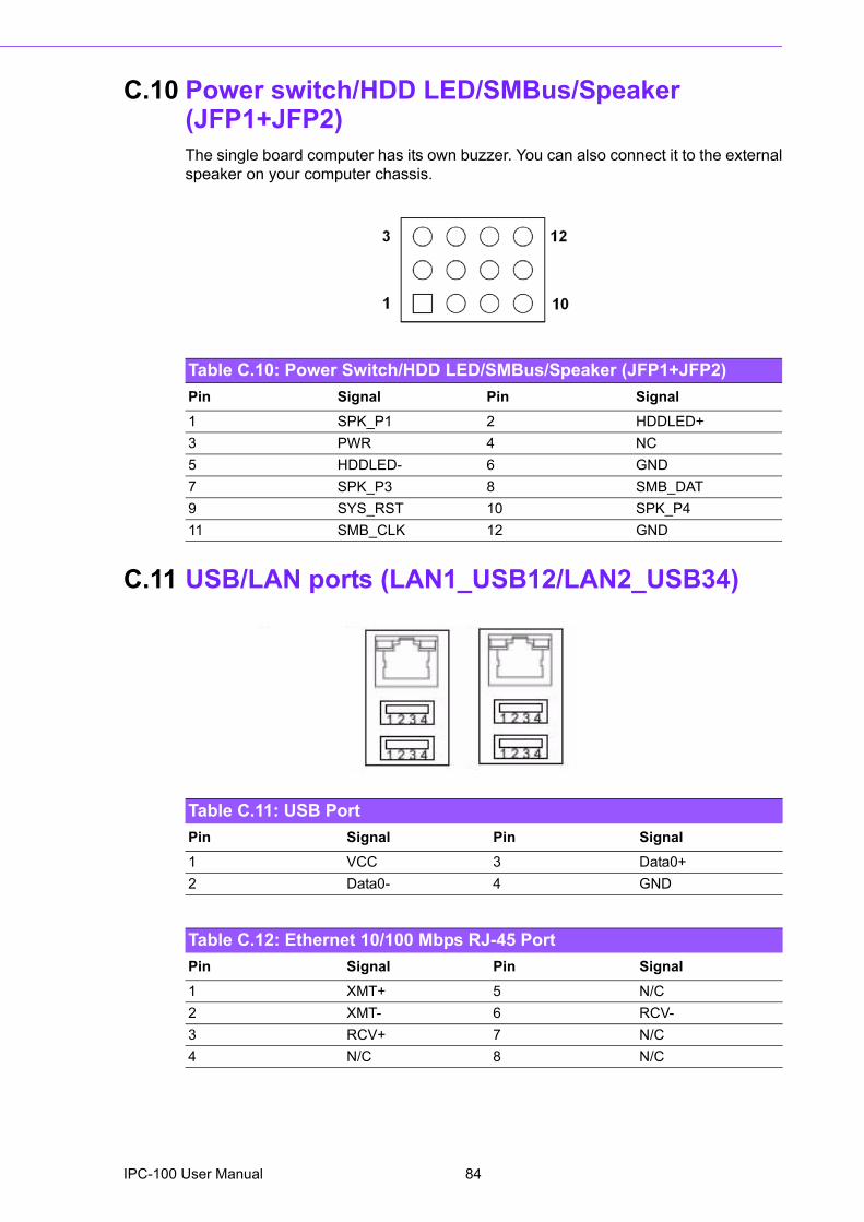
C.10 Power switch/HDD LED/SMBus/Speaker (JFP1+JFP2)The single board computer has its own buzzer. You can also connect it to the externalspeaker on your computer chassis.
C.11 USB/LAN ports (LAN1_USB12/LAN2_USB34)
Table C.10: Power Switch/HDD LED/SMBus/Speaker (JFP1+JFP2)Pin Signal Pin Signal1 SPK_P1 2 HDDLED+3 PWR 4 NC5 HDDLED- 6 GND7 SPK_P3 8 SMB_DAT9 SYS_RST 10 SPK_P411 SMB_CLK 12 GND
Table C.11: USB PortPin Signal Pin Signal1 VCC 3 Data0+2 Data0- 4 GND
Table C.12: Ethernet 10/100 Mbps RJ-45 PortPin Signal Pin Signal1 XMT+ 5 N/C2 XMT- 6 RCV-3 RCV+ 7 N/C4 N/C 8 N/C
IPC-100 User Manual 84
Appendix C
I/O P
inA
ssignments
C.12 Line Out, Mic In Connector (AUDIO1)
C.13 Serial ATA0/1 (SATA1/SATA2)
C.14 AT/ATX Mode (PSON1)
C.15 HD Audio Interface (HD1)
Line Out
Mic In
Table C.13: Serial ATA 0/1 (SATA1/SATA2)Pin Signal Pin Signal1 GND 2 SATA_0TX+3 SATA_0TX- 4 GND5 SATA_0RX- 6 SATA_0RX+7 GND 8
Table C.14: AT/ATX Mode (PSON1)Pin Signal Pin Signal1 #PSON_SIO
(to super IO)2 #PSON
(to power supply)3 GND
Table C.15: AC-97 Audio Interface (HD1)Pin Signal Pin Signal1 MIC2_L 2 GND3 MIC2_R 4 FP_AUD_DET5 LOUT2_R 6 SRTN17 LOUT2_DET 8 KEY9 LOUT2_L 10 SRTN2
1
9
85 IPC-100 User Manual
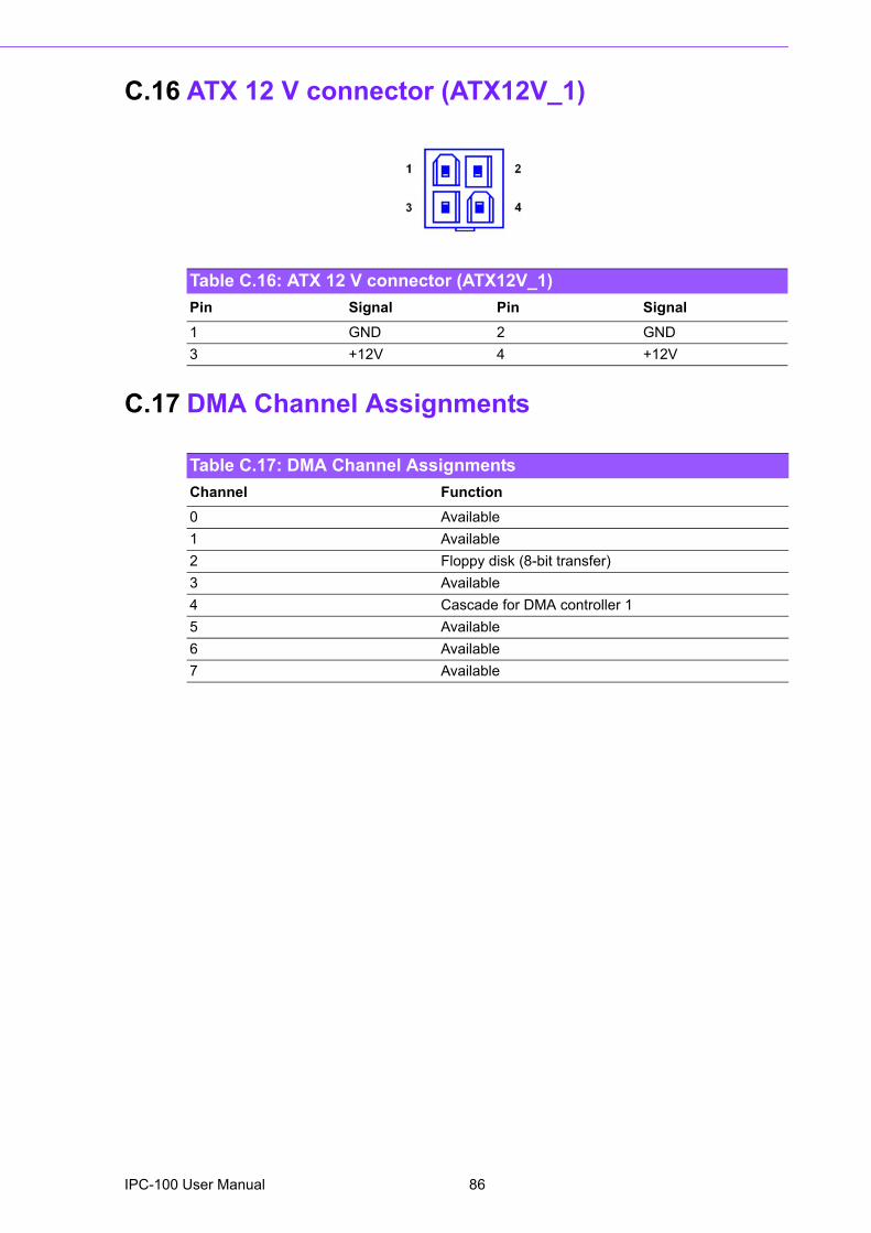
C.16 ATX 12 V connector (ATX12V_1)
C.17 DMA Channel Assignments
Table C.16: ATX 12 V connector (ATX12V_1)Pin Signal Pin Signal1 GND 2 GND 3 +12V 4 +12V
Table C.17: DMA Channel AssignmentsChannel Function0 Available1 Available2 Floppy disk (8-bit transfer)3 Available4 Cascade for DMA controller 15 Available6 Available7 Available
IPC-100 User Manual 86
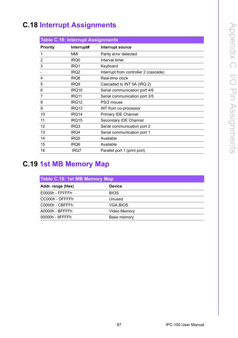
Appendix C
I/O P
inA
ssignments
C.18 Interrupt Assignments
C.19 1st MB Memory Map
Table C.18: Interrupt AssignmentsPriority Interrupt# Interrupt source1 NMI Parity error detected2 IRQ0 Interval timer3 IRQ1 Keyboard- IRQ2 Interrupt from controller 2 (cascade)4 IRQ8 Real-time clock5 IRQ9 Cascaded to INT 0A (IRQ 2)6 IRQ10 Serial communication port 4/67 IRQ11 Serial communication port 3/58 IRQ12 PS/2 mouse9 IRQ13 INT from co-processor10 IRQ14 Primary IDE Channel11 IRQ15 Secondary IDE Channel12 IRQ3 Serial communication port 213 IRQ4 Serial communication port 114 IRQ5 Available15 IRQ6 Available16 IRQ7 Parallel port 1 (print port)
Table C.19: 1st MB Memory MapAddr. range (Hex) DeviceE0000h - FFFFFh BIOSCC000h - DFFFFh UnusedC0000h - CBFFFh VGA BIOSA0000h - BFFFFh Video Memory00000h - 9FFFFh Base memory
87 IPC-100 User Manual

www.advantech.comPlease verify specifications before quoting. This guide is intended for referencepurposes only.All product specifications are subject to change without notice.No part of this publication may be reproduced in any form or by any means,electronic, photocopying, recording or otherwise, without prior written permis-sion of the publisher.All brand and product names are trademarks or registered trademarks of theirrespective companies.© Advantech Co., Ltd. 2010