Embed Size (px)
Citation preview
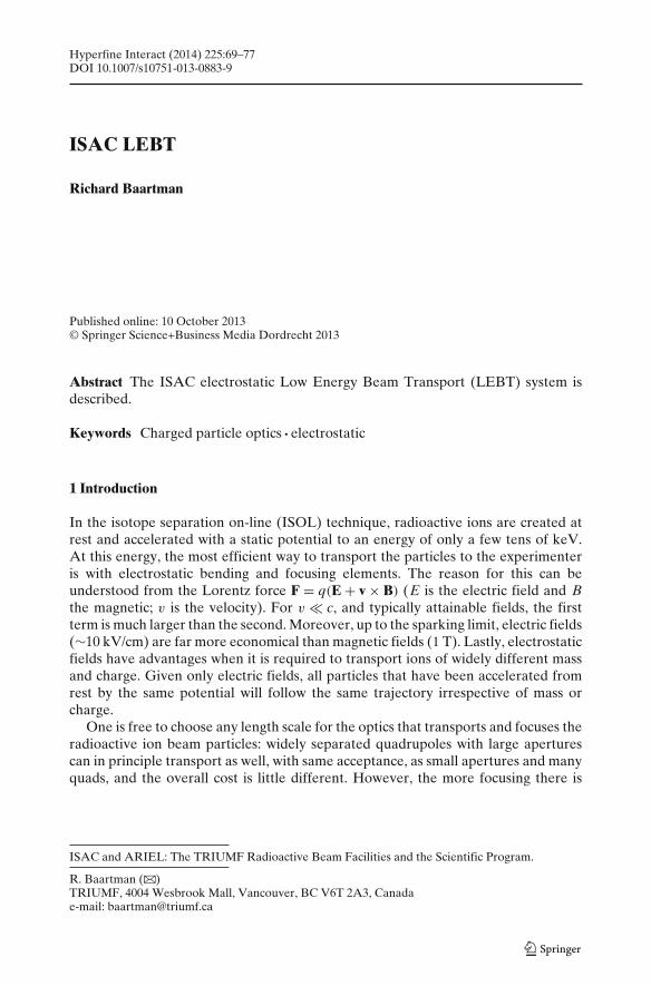
Hyperfine Interact (2014) 225:69–77DOI 10.1007/s10751-013-0883-9
ISAC LEBT
Richard Baartman
Published online: 10 October 2013© Springer Science+Business Media Dordrecht 2013
Abstract The ISAC electrostatic Low Energy Beam Transport (LEBT) system isdescribed.
Keywords Charged particle optics · electrostatic
1 Introduction
In the isotope separation on-line (ISOL) technique, radioactive ions are created atrest and accelerated with a static potential to an energy of only a few tens of keV.At this energy, the most efficient way to transport the particles to the experimenteris with electrostatic bending and focusing elements. The reason for this can beunderstood from the Lorentz force F = q(E + v × B) (E is the electric field and Bthe magnetic; v is the velocity). For v � c, and typically attainable fields, the firstterm is much larger than the second. Moreover, up to the sparking limit, electric fields(∼10 kV/cm) are far more economical than magnetic fields (1 T). Lastly, electrostaticfields have advantages when it is required to transport ions of widely different massand charge. Given only electric fields, all particles that have been accelerated fromrest by the same potential will follow the same trajectory irrespective of mass orcharge.
One is free to choose any length scale for the optics that transports and focuses theradioactive ion beam particles: widely separated quadrupoles with large aperturescan in principle transport as well, with same acceptance, as small apertures and manyquads, and the overall cost is little different. However, the more focusing there is
ISAC and ARIEL: The TRIUMF Radioactive Beam Facilities and the Scientific Program.
R. Baartman (B)TRIUMF, 4004 Wesbrook Mall, Vancouver, BC V6T 2A3, Canadae-mail: [email protected]
70 R. Baartman
per unit length, the less effected is the beam by perturbations such as stray magneticfields and misalignments. This favours many small quadrupoles over few large ones.
2 Standard modules
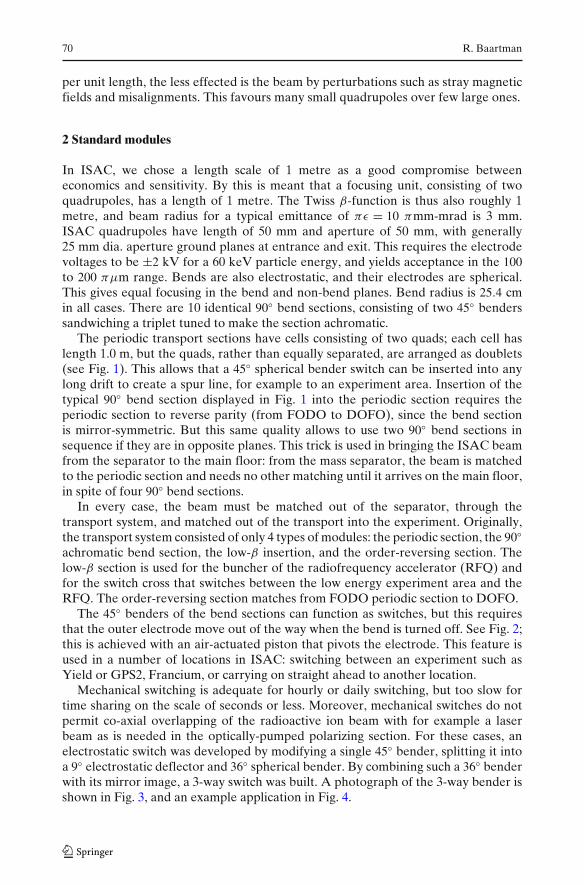
In ISAC, we chose a length scale of 1 metre as a good compromise betweeneconomics and sensitivity. By this is meant that a focusing unit, consisting of twoquadrupoles, has a length of 1 metre. The Twiss β-function is thus also roughly 1metre, and beam radius for a typical emittance of πε = 10 πmm-mrad is 3 mm.ISAC quadrupoles have length of 50 mm and aperture of 50 mm, with generally25 mm dia. aperture ground planes at entrance and exit. This requires the electrodevoltages to be ±2 kV for a 60 keV particle energy, and yields acceptance in the 100to 200 πμm range. Bends are also electrostatic, and their electrodes are spherical.This gives equal focusing in the bend and non-bend planes. Bend radius is 25.4 cmin all cases. There are 10 identical 90◦ bend sections, consisting of two 45◦ benderssandwiching a triplet tuned to make the section achromatic.
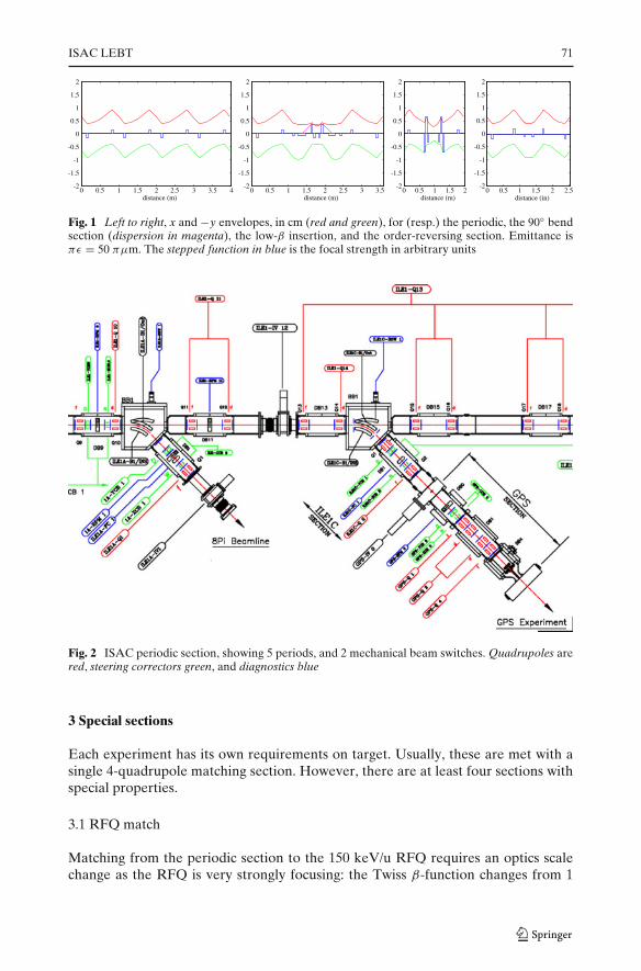
The periodic transport sections have cells consisting of two quads; each cell haslength 1.0 m, but the quads, rather than equally separated, are arranged as doublets(see Fig. 1). This allows that a 45◦ spherical bender switch can be inserted into anylong drift to create a spur line, for example to an experiment area. Insertion of thetypical 90◦ bend section displayed in Fig. 1 into the periodic section requires theperiodic section to reverse parity (from FODO to DOFO), since the bend sectionis mirror-symmetric. But this same quality allows to use two 90◦ bend sections insequence if they are in opposite planes. This trick is used in bringing the ISAC beamfrom the separator to the main floor: from the mass separator, the beam is matchedto the periodic section and needs no other matching until it arrives on the main floor,in spite of four 90◦ bend sections.
In every case, the beam must be matched out of the separator, through thetransport system, and matched out of the transport into the experiment. Originally,the transport system consisted of only 4 types of modules: the periodic section, the 90◦achromatic bend section, the low-β insertion, and the order-reversing section. Thelow-β section is used for the buncher of the radiofrequency accelerator (RFQ) andfor the switch cross that switches between the low energy experiment area and theRFQ. The order-reversing section matches from FODO periodic section to DOFO.
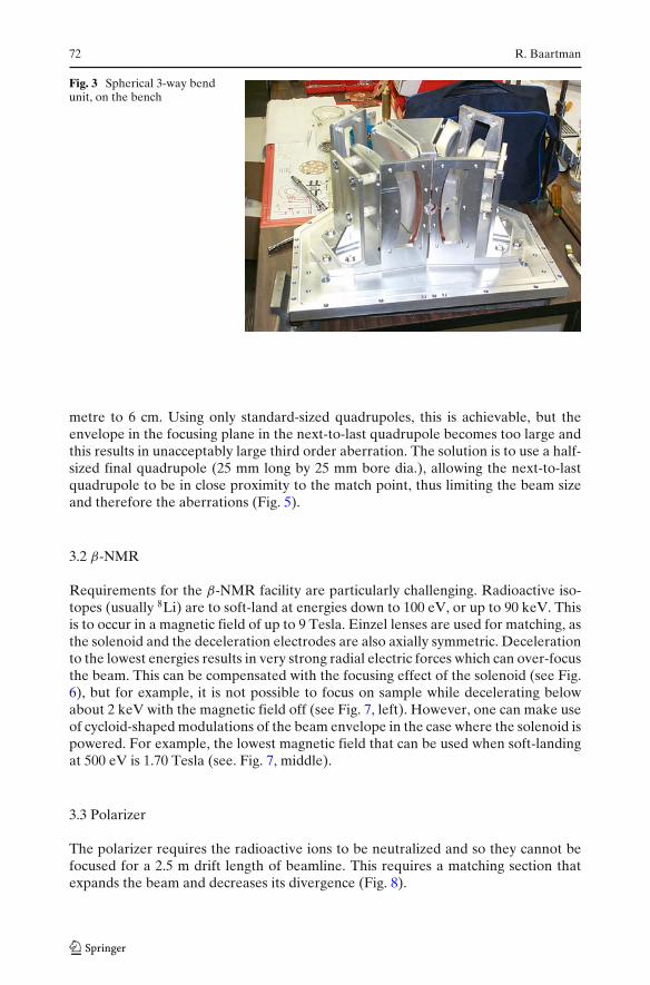
The 45◦ benders of the bend sections can function as switches, but this requiresthat the outer electrode move out of the way when the bend is turned off. See Fig. 2;this is achieved with an air-actuated piston that pivots the electrode. This feature isused in a number of locations in ISAC: switching between an experiment such asYield or GPS2, Francium, or carrying on straight ahead to another location.
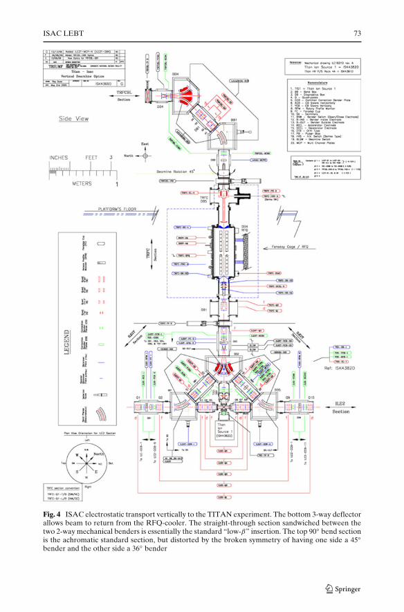
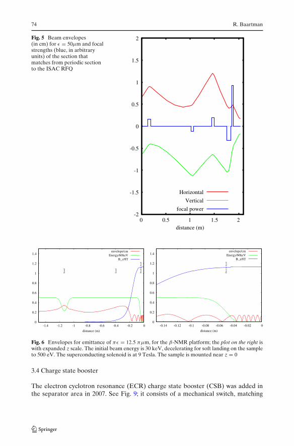
Mechanical switching is adequate for hourly or daily switching, but too slow fortime sharing on the scale of seconds or less. Moreover, mechanical switches do notpermit co-axial overlapping of the radioactive ion beam with for example a laserbeam as is needed in the optically-pumped polarizing section. For these cases, anelectrostatic switch was developed by modifying a single 45◦ bender, splitting it intoa 9◦ electrostatic deflector and 36◦ spherical bender. By combining such a 36◦ benderwith its mirror image, a 3-way switch was built. A photograph of the 3-way bender isshown in Fig. 3, and an example application in Fig. 4.
ISAC LEBT 71
-2
-1.5
-1
-0.5
0
0.5
1
1.5
2
0 0.5 1 1.5 2 2.5distance (in)
-2
-1.5
-1
-0.5
0
0.5
1
1.5
2
0 0.5 1 1.5 2 2.5 3 3.5 4distance (m)
-2
-1.5
-1
-0.5
0
0.5
1
1.5
2
0 0.5 1 1.5 2 2.5 3 3.5distance (m)
-2
-1.5
-1
-0.5
0
0.5
1
1.5
2
0 0.5 1 1.5 2distance (m)
Fig. 1 Left to right, x and −y envelopes, in cm (red and green), for (resp.) the periodic, the 90◦ bendsection (dispersion in magenta), the low-β insertion, and the order-reversing section. Emittance isπε = 50 πμm. The stepped function in blue is the focal strength in arbitrary units
Fig. 2 ISAC periodic section, showing 5 periods, and 2 mechanical beam switches. Quadrupoles arered, steering correctors green, and diagnostics blue
3 Special sections
Each experiment has its own requirements on target. Usually, these are met with asingle 4-quadrupole matching section. However, there are at least four sections withspecial properties.
3.1 RFQ match
Matching from the periodic section to the 150 keV/u RFQ requires an optics scalechange as the RFQ is very strongly focusing: the Twiss β-function changes from 1
72 R. Baartman
Fig. 3 Spherical 3-way bendunit, on the bench
metre to 6 cm. Using only standard-sized quadrupoles, this is achievable, but theenvelope in the focusing plane in the next-to-last quadrupole becomes too large andthis results in unacceptably large third order aberration. The solution is to use a half-sized final quadrupole (25 mm long by 25 mm bore dia.), allowing the next-to-lastquadrupole to be in close proximity to the match point, thus limiting the beam sizeand therefore the aberrations (Fig. 5).
3.2 β-NMR
Requirements for the β-NMR facility are particularly challenging. Radioactive iso-topes (usually 8Li) are to soft-land at energies down to 100 eV, or up to 90 keV. Thisis to occur in a magnetic field of up to 9 Tesla. Einzel lenses are used for matching, asthe solenoid and the deceleration electrodes are also axially symmetric. Decelerationto the lowest energies results in very strong radial electric forces which can over-focusthe beam. This can be compensated with the focusing effect of the solenoid (see Fig.6), but for example, it is not possible to focus on sample while decelerating belowabout 2 keV with the magnetic field off (see Fig. 7, left). However, one can make useof cycloid-shaped modulations of the beam envelope in the case where the solenoid ispowered. For example, the lowest magnetic field that can be used when soft-landingat 500 eV is 1.70 Tesla (see. Fig. 7, middle).
3.3 Polarizer
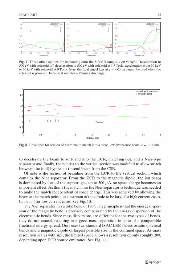
The polarizer requires the radioactive ions to be neutralized and so they cannot befocused for a 2.5 m drift length of beamline. This requires a matching section thatexpands the beam and decreases its divergence (Fig. 8).
ISAC LEBT 73
Fig. 4 ISAC electrostatic transport vertically to the TITAN experiment. The bottom 3-way deflectorallows beam to return from the RFQ-cooler. The straight-through section sandwiched between thetwo 2-way mechanical benders is essentially the standard “low-β” insertion. The top 90◦ bend sectionis the achromatic standard section, but distorted by the broken symmetry of having one side a 45◦bender and the other side a 36◦ bender
74 R. Baartman
Fig. 5 Beam envelopes(in cm) for ε = 50μm and focalstrengths (blue, in arbitraryunits) of the section thatmatches from periodic sectionto the ISAC RFQ
-2
-1.5
-1
-0.5
0
0.5
1
1.5
2
0 0.5 1 1.5 2distance (m)
Horizontal
Vertical
focal power
0
0.2
0.4
0.6
0.8
1
1.2
1.4
-0.14 -0.12 -0.1 -0.08 -0.06 -0.04 -0.02 0
distance (m)
Dec
el o
r A
ccel
envelope/cmEnergy/60keV
B_z/8T
0
0.2
0.4
0.6
0.8
1
1.2
1.4
-1.4 -1.2 -1 -0.8 -0.6 -0.4 -0.2 0
distance (m)
Ein
zel
Ein
zel
Dec
el o
r A
ccel
envelope/cmEnergy/60keV
B_z/8T
Fig. 6 Envelopes for emittance of πε = 12.5 πμm, for the β-NMR platform; the plot on the right iswith expanded z scale. The initial beam energy is 30 keV, decelerating for soft landing on the sampleto 500 eV. The superconducting solenoid is at 9 Tesla. The sample is mounted near z = 0
3.4 Charge state booster
The electron cyclotron resonance (ECR) charge state booster (CSB) was added inthe separator area in 2007. See Fig. 9; it consists of a mechanical switch, matching
ISAC LEBT 75
0
0.2
0.4
0.6
0.8
1
1.2
1.4
-0.5 -0.4 -0.3 -0.2 -0.1 0distance (m)
Ein
zel
Dec
el o
r A
ccel
envelope/cmEnergy/60keV
B_z/8T
0
0.2
0.4
0.6
0.8
1
1.2
1.4
-0.5 -0.4 -0.3 -0.2 -0.1 0distance (m)
Ein
zel
Dec
el o
r A
ccel
envelope/cmEnergy/60keV
B_z/8T
0
0.2
0.4
0.6
0.8
1
1.2
1.4
-0.5 -0.4 -0.3 -0.2 -0.1 0distance (m)
Ein
zel
Dec
el o
r A
ccel
envelope/cmEnergy/60keV
B_z/8T
Fig. 7 Three other options for implanting onto the β-NMR sample. Left to right: Deceleration to500 eV with solenoid off, deceleration to 500 eV with solenoid at 1.7 Tesla, acceleration from 30 keVto 60 keV with solenoid at 9 Tesla. Note: the final einzel lens at z = −0.4 m cannot be used when thesolenoid is powered, because it initiates a Penning discharge
-2
-1.5
-1
-0.5
0
0.5
1
1.5
2
0 0.5 1 1.5 2 2.5 3 3.5 4distance (m)
Q11
Q12
Q13
Q14
Q15
Polarizer
x-envelope (cm)y-envelope (cm)
Fig. 8 Envelopes for section of beamline to match into a large, low divergence beam. ε = 12.5 μm
to decelerate the beam to soft-land into the ECR, matching out, and a Nier-typeseparator and finally, the bender to the vertical section was modified to allow switchbetween the (old) bypass, or to send beam from the CSB.
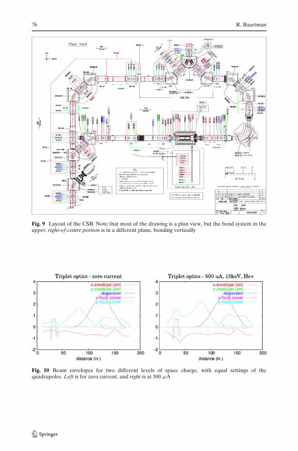
Of note is the section of beamline from the ECR to the vertical section, whichcontains the Nier separator. From the ECR to the magnetic dipole, the ion beamis dominated by ions of the support gas, up to 500 μA, so space charge becomes animportant effect. As this is the match into the Nier separator, a technique was neededto make the match independent of space charge. This was achieved by allowing thebeam at the match point just upstream of the dipole to be large for high current cases,but small for low current cases. See Fig. 10.
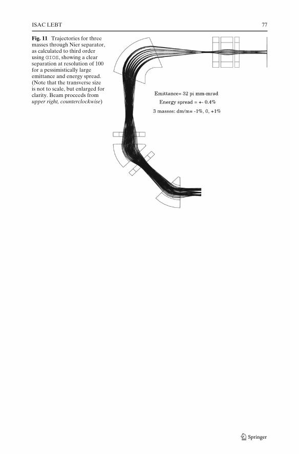
The Nier separator has a total bend of 180◦. The principle is that the energy disper-sion of the magnetic bend is precisely compensated by the energy dispersion of theelectrostatic bends. Since mass dispersions are different for the two types of bends,they do not cancel, resulting in a good mass separation in spite of a comparablefractional energy spread. Ours uses two standard ISAC LEBT electrostatic sphericalbends and a magnetic dipole of largest possible size in the confined space. As massresolution scales with size, the limited space allows a resolution of only roughly 200,depending upon ECR source emittance. See Fig. 11.
76 R. Baartman
Fig. 9 Layout of the CSB. Note that most of the drawing is a plan view, but the bend system in theupper, right-of-centre portion is in a different plane, bending vertically
Fig. 10 Beam envelopes for two different levels of space charge, with equal settings of thequadrupoles. Left is for zero current, and right is at 500 μA
ISAC LEBT 77
Fig. 11 Trajectories for threemasses through Nier separator,as calculated to third orderusing GIOS, showing a clearseparation at resolution of 100for a pessimistically largeemittance and energy spread.(Note that the transverse sizeis not to scale, but enlarged forclarity. Beam proceeds fromupper right, counterclockwise)