Embed Size (px)
Citation preview

Universität Stuttgart
Institut für Konstruktion undFertigung in der Feinwerktechnik
Jahresbericht IKFF 2013

Herausgeber und Verlag:Institut für Konstruktion und Fertigung in der FeinwerktechnikPfaffenwaldring 970550 Stuttgart
Tel.: 0711 685-66402Fax: 0711 685-56402
Prof. Dr.-Ing. Wolfgang SchinkötheInstitut für Konstruktion und Fertigung in der Feinwerktechnik, Februar 2014
1 DAS INSTITUT1.1 Mitarbeiter1.2 Jahresrückblick1.3 Wissenschaftliche Arbeitsgebiete
2 LEHRVERANSTALTUNGEN2.1 Vorlesungen und Übungen für das Bachelorstudium2.2 Vorlesungen und Übungen für das Masterstudium und das Hauptdiplom2.3 Prüfungen2.4 Praktika2.5 Projektarbeiten 2.6 Seminar Feinwerktechnik
3 WISSENSCHAFTLICHE ARBEITEN, STUDIEN-, DIPLOM- UND BACHELOR-ARBEITEN
3.1 Dissertationen3.2 Diplomarbeiten am IKFF 3.3 Bachelorarbeiten am IKFF3.4 Studienarbeiten am IKFF3.5 Preise
4 ARBEITSGEBIETE DER WISSENSCHAFTLICHEN MITARBEITER4.1 Aktorik4.2 Spritzgießen 4.3 Zuverlässigkeitstechnik
5 ÖFFENTLICHKEITSARBEIT5.1 Veröffentlichungen5.2 Gremienarbeit5.3 Tag der Wissenschaft
6 KONGRESSE, TAGUNGEN UND MESSEN
7 WERKSTATTBERICHT
8 ANHANG - Ausgewählte Veröffentlichungen

1
1 DAS INSTITUT
1.1 Mitarbeiter
Institutsleitung:Prof. Dr.-Ing. Wolfgang Schinköthe
Emeritus:Prof. Dipl.-Ing. Artur Jung
Sekretariat:Ulrike OrtnerKornelia Wanner
Unbefristeter wissenschaftlicher Mitarbeiter:Akademischer Oberrat: Dipl.-Ing. Eberhard Burkard
Befristete wissenschaftliche Mitarbeiter:Dipl.-Ing. Hakan AkkayaDipl.-Ing. Sebastian BobrowskiDipl.-Ing. Matthias Engel (Graduate Student der GSaME)Dipl.-Ing. Bastian KellerDipl.-Ing. Judith KoflerDipl.-Ing. (FH) Daniel Kreuzer (Graduate Student der GSaME)Dipl.-Ing. Matthias MaierDipl.-Ing. Andreas MaucherDipl.-Ing. Minh Nguyen (Graduate Student der GSaME)Dipl.-Ing. Adrian RetzbachDipl.-Ing. Benjamin ReutzschDipl.-Ing. Gregor SchattkaDipl.-Ing. Matthias Ulmer
Modellbau und Versuchswerkstatt:Ralf Berwanger Stefan Schneider
2
Wissenschaftliche Hilfskräfte:Beckert, MarkusDürr, ChristianJunginger, EliasKarlowitz, AndreasKayarat, RekhaKraus, CorinnaLaabs, Kevin
Litwin, ThomasMaul, MarkusNußbaumer, RalfRiggenmann, SimonSchneider, MarcelStrohmeyr, Simon
1.2 Jahresrückblick
PersonaliaIm Jahr 2013 wurde ein neuer wissenschaftlicher Mitarbeiter eingestellt (Dipl.-Ing.Andreas Maucher), liefen zwei Arbeitsverträge planmäßig aus (Dipl.-Ing. MatthiasUlmer, Dipl.-Ing. Hakan Akkaya) und kam ein neuer Stipendiat der GSaME ans IKFF(Dipl.-Ing. (FH) Daniel Kreuzer).
Aktivitäten in der LehreSeit Oktober 2011 laufen im Maschinenbau die Masterstudiengänge, unter anderemauch der Masterstudiengang Maschinenbau/ Mikrotechnik, Gerätetechnik und Tech-nische Optik (Studiendekan Prof. Schinköthe, Studiengangsmanager Herr Burkard).Zuspruch zu unserem Master gibt es vor allem von außen, aus anderenUniversitäten, Fachhochschulen bzw. aus Dualen Hochschulen. Bisher hat derMaster 44 eingeschriebene Studierende. Die Studierendenzahl liegt noch leichtunter der langfristigen Zielstellung von 25 Immatrikulationen pro Jahr.
Die Anfängerzahlen im Maschinenbau sind konstant hoch. Die Anfängerzahlen allermaschinenbaulichen Studiengänge der Universität Stuttgart (ohne Luft- undRaumfahrttechnik) lagen wie schon im Vorjahr auch im Jahr 2013 bei ca. 1100 Stu-dierenden. Im Studiengang Maschinenwesen selbst bewegen sich die Anfängerzah-len wie im Vorjahr bei ca. 370. Hinzu kommen noch insgesamt ca. 625 neuimmatrikulierte Masterstudierende in allen Mastern der Fakultät, was einer Steigerunggegenüber dem Vorjahr um 50 % entspricht. Alle Fakultätsstudiengänge sindausgelastet, inklusive freiwilliger Überlast.
In der Konstruktionslehre Feinwerktechnik hatten wir bis zum Sommer 76Studierende zu betreuen, im Wintersemester haben 85 Studierende den Zyklusneu begonnen. Die Bachelor-Lehrveranstaltungen konzentrierten sich nach wie
3
vor auf die Fächer Konstruktionslehre Feinwerktechnik III und IV im dritten undvierten Semester als Wahlmöglichkeit für die beiden BachelorstudiengängeMaschinenbau sowie Fahrzeug- und Motorentechnik. Ein Highlight ist dabei immerwieder der Konstruktionswettbewerb, auf den weiter hinten noch eingegangen wird.
Im Hauptfach laufen die Diplomstudiengänge aus und die Master werdendominierend. Derzeit begannen 48 Studierende im Fach „Gerätekonstruktion und-fertigung in der Feinwerktechnik” als Pflicht- oder Kernfach. 24 Studierende startetenim Kernfach „Aktorik”. Das Fach „Praxis des Spritzgießens in der Gerätetechnik,Verfahren, Prozesskette, Simulation” belegten 5 Studierende, es ist noch im Aufbau,die „Praktische FEM Simulation mit ANSYS und MAXWELL” belegten 17Studierende. Im vergangenen Jahr hatten wir zudem mit 35 Studien-, Bachelor-und Diplomarbeiten wieder einen enormen Zuspruch in diesem Bereich. Hinzu kamennochmals 30 Studierende in Projektarbeiten.
Die Lehrveranstaltungen des Hauptdiploms konzentrieren sich auf die beidenSchwerpunkte Gerätekonstruktion als methodisch orientierte Linie und feinwerk-technische Aktorik als konkret forschungs- und entwicklungsorientierte Linie, ergänztdurch die Lehrveranstaltungen Praxis des Spritzgießens und Praktische FEM-Simulation mit ANSYS und MAXWELL.
Die Vorlesung „Gerätekonstruktion und -fertigung in der Feinwerktechnik ” behandeltGrundlagen der Entwicklung und Konstruktion feinwerktechnischer Geräte bzw.Systeme. Den Schwerpunkt bilden Themenkreise wie zuverlässigkeits- undsicherheitsgerechte Konstruktion, Genauigkeit, Fehlerverhalten und Toleranz-rechnung in der Präzisionsgerätetechnik, Lärmminderung in der Gerätetechnik sowieBeziehungen zwischen Gerät und Umwelt. Eingeschlossen in die Lehrveranstaltungsind drei praktische Bestandteile, zur Einführung in die Koordinatenmesstechnik,zur Zuverlässigkeit und zur Geräuschmessung und Lärmminderung.
Die Vorlesung „Aktorik in der Feinwerktechnik - Konstruktion, Berechnung undAnwendung mechatronischer Komponenten” beleuchtet dagegen ausgewählteAspekte der Entwicklung und Konstruktion mechatronischer Komponenten undSysteme der Feinwerktechnik. Behandelt werden feinwerktechnische Antriebs-systeme unterschiedlichster Wirkprinzipien. Den Schwerpunkt bilden elek-tromagnetische und elektrodynamische Stelltechnik, piezoelektrische undmagnetostriktive Stelltechnik, Magnettechnik und -technologie sowie Beispiele zurRealisierung mechatronischer Lösungen in der Feinwerktechnik.
4
Unsere Lehrveranstaltung „Praktische FEM-Simulation mit ANSYS und MAXWELL”wurde wieder sehr gut angenommen und ist mit 17 Studierenden sehr gutausgelastet. Auch unsere Lehrveranstaltung „Praxis des Spritzgießens in derGerätetechnik; Verfahren, Prozesskette, Simulation” fand 2013, wenn auch mitkleiner Teilnehmerzahl, wieder erfolgreich statt. Diese Vorlesung wird ab SS 2012mit dem doppelten Umfang (4 SWS) gelesen und beinhaltet den gesamten KomplexSpritzgießen.
Die Hauptfachpraktika Ultraschallantriebe, Lineardirektantriebe, Schrittmotoren,Gleichstrommotoren, Koordinatenmesstechnik, FEM-Berechnung mit ANSYS sowieMAXWELL, Spritzgießen inklusive Spritzgieß-Simulation mit Moldflow sind in dieLehrveranstaltungen einbezogen. Mit diesen insgesamt 7 Praktika wurde ein solidesAngebot zum praktischen Arbeiten für die Studierenden geschaffen.
Die Absolventen fanden auch 2013 problemlos ihren Einstieg in die Industrie.
Aktivitäten in der ForschungDie Entwicklung alternativer Antriebssysteme für die Feinwerktechnik auf der Basiselektrodynamischer Kraftwirkung (elektrodynamische Linearmotoren) bzw. vonFestkörpereffekten steht nach wie vor im Mittelpunkt des Arbeitsgebiets Aktorik.
Als Schwerpunkt in der Nutzung elektrodynamischer Antriebsprinzipien wurden 2013Untersuchungen zu magnetischen Führungen weitergeführt. Die Forschungen zurEntwicklung von neuartigen Direktantrieben mit piezoelektrischen Antrieben wurdenebenfalls fortgeführt. Generell bilden dabei neben der Motorentwicklung unddurchgängigen Motorberechnung bzw. -simulation die Realisierung von Ansteuerungund Regelung über eine dSPACE-Entwicklungsumgebung einen Schwerpunkt. BeideAntriebslinien ergänzen und befruchten sich gegenseitig.
Das Thema Spritzgießtechnologie in der Feinwerktechnik bildet einen weiterenStützpfeiler des Instituts. Nach wie vor werden am IKFF die Entformungskräfte beimSpritzgießen in Abhängigkeit von Oberflächenrauheit und Beschichtung sowie vomeingesetzten Kunststoff untersucht und spezielle Werkstoffe und Beschichtungenfür Firmen getestet. Dazu lief ein ZIM-Projekt. Darüber hinaus wurden im Jahre2013 die Arbeiten zur variothermen Prozessführung mit integrierten Induktoren undImpulskühlung sowie zur Nutzung der Induktionserwärmung für andere Aufgaben(induktives Kleben) weiterbetrieben. Ergebnisse dazu sind mehrfach veröffentlicht.Auch hierzu liefen insgesamt drei ZIM-Projekte, die der breiten Überführung dieserErkenntnisse dienen.
5
Im Arbeitsgebiet Zuverlässigkeit feinwerktechnischer Antriebe wurde dasgemeinsame DFG-Projekt (Normalverfahren) zusammen mit der UniversitätHohenheim weitergeführt. Ziel ist dabei eine Zuverlässigkeitsprognose in frühenEntwicklungsphasen mit Hilfe statistischer Modelle. Mit den zu entwickelndenPrognosesystemen sollen effiziente Werkzeuge für die Nutzung vorhandenerAusfalldaten zur statistischen Vorhersage des Ausfallverhaltens bei nicht unmittelbargetesteten Parametersätzen in verschiedenen Phasen der Entwicklungs- undLebenszyklen verfügbar werden. Derzeit stehen Dauerversuche zur Ermittlung derAusfalldaten vorzugsweise an Kleingetrieben und entsprechende Prognosemodulefür Motoren und Getriebe im Mittelpunkt.
Generell werden dabei am Institut neben oder innerhalb dieser Forschungsarbeitenauch eine Vielzahl von Industrieprojekten realisiert.
1.3 Wissenschaftliche Arbeitsgebiete
Im Institut werden vier Forschungsschwerpunkte bearbeitet:
Im Arbeitsgebiet Aktorik stehen feinwerktechnische Direktantriebe, vorzugsweisefür lineare Antriebsbewegungen, im Mittelpunkt. Einen Schwerpunkt bilden elektrody-namische Linearantriebe, deren Berechnung und Simulation. Zusätzlich wurdendie Aktivitäten auch auf die Entwicklung von Luftführungen und magnetischeSchwebeführungen für Linearantriebe erweitert. Neben den elektrodynamischenSystemen bilden piezoelektrische Antriebe einen zweiten Arbeitsschwerpunkt.
Im Arbeitsgebiet Präzisionsspritzguss steht die Abformung von Präzisionsbauteilenmit sehr feinen, genauen Strukturen durch Spritzgießen im Vordergrund. Dabei wirdneben der Bauteilkonstruktion und dem Formenbau insbesondere der Form-füllvorgang sowohl theoretisch simuliert als auch praktisch an zwei Spritzgieß-automaten untersucht. Maßnahmen zur Verbesserung des Füllvorgangs, wie dievariotherme Prozessführung durch induktive Formtemperierung, sowie die Erfassungvon Entformungskräften bilden gegenwärtig die Arbeitsschwerpunkte. Neuerdingskommen auch Aktivitäten zum Magnetspritzgießen hinzu.
Im Arbeitsgebiet optische und mechanische Sensorik standen bisher insbesonderedie Verfahren zur integrierten Wegsignalerfassung in elektrodynamischenLinearmotoren mit bewegten Magneten oder auch bewegten Spulen im Mittelpunktder Arbeiten.
6
Übergreifend bildet produktbezogene Konstruktionsmethodik in der Feinwerk-technik ein viertes Arbeitsgebiet. Schwerpunkte sind hier die konstruktive Gestaltung,die Berechnung von Systemen und die Simulation mit FEM. Dazu zählen auchMagnetfeldberechnungen sowie thermische Berechnungen für Linearantriebe oderdie FEM-Analyse von piezoelektrischen Antrieben.
Auch das Arbeitsgebiet Zuverlässigkeit feinwerktechnischer Antriebe lässt sichin diesen Problemkreis einordnen. Hier arbeitet das Institut auf dem Gebiet derZuverlässigkeit von elektromechanischen/mechatronischen Systemen am Beispielfeinwerktechnischer Antriebe/Aktorik. Dies betrifft sowohl die elektromechanischenals auch die mechanischen Komponenten derartiger Antriebe.
Im Detail werden folgende Inhalte bearbeitet:
Feinwerktechnische Aktorik- Entwicklung alternativer Antriebssysteme für die Feinwerktechnik auf der Basis
elektrodynamischer Kraftwirkung bzw. von Festkörpereffekten (elektrodynamischeLinearmotoren, Piezomotoren).
- Berechnung derartiger Antriebe und Simulation ihres dynamischen Verhaltens.- Erarbeitung geeigneter Unterstützungsmittel und Methoden zur Entwicklung
derartiger Antriebssysteme.- Entwicklung von magnetischen Schwebeführungen für Linearantriebe.
Präzisions-Spritzgießtechnologie- Herstellung von Präzisionsbauteilen und feinen Strukturen bis hin zur Verbindung
mit mikromechanischen Bauelementen.- Ermittlung von Entformungskräften beim Spritzgießen in Abhängigkeit von
Oberflächenrauheit und Beschichtung sowie vom eingesetzten Kunststoff.- Untersuchung spezieller Werkstoffe und Beschichtungen im Werkzeugbau.- Dynamische Formtemperierung durch induktive Beheizung mit externem oder
internem Induktor zur Verbesserung des Formfüllverhaltens, insbesondere imHinblick auf die Abformung mikrotechnischer Strukturen.
- Magnetspitzgießen.- Erweiterung der induktiven Erwärmung auf weitere Anwendungen (induktiv
unterstütztes Kleben).
Theorie des Konstruktionsprozesses- Produktbezogene Konstruktionsmethoden in der Feinwerktechnik.- Konstruktive Gestaltung unter Nutzung von 2D- und 3D-CAD.- Simulation mit FEM, beispielsweise des Formfüllvorgangs beim Spritzgießen.

7
- Gekoppelte Feldberechnungen, beispielsweise elektromagnetisch, elektromagne-tisch-thermisch, piezoelektrisch-dynamisch.
Zuverlässigkeit feinwerktechnischer Antriebe- Übertragung und Verifizierung bekannter Zuverlässigkeitstechniken auf feinwerk-
technische mechatronische Baugruppen, Antriebe und Aktorik.- Datensammlung.- Experimentelle Untersuchungen, Aufbau von Dauerlauf-Versuchsständen für
Kleinstmotoren und Getriebe.- Erarbeitung von Ansätzen für die Ermittlung der Systemzuverlässigkeit in frühen
Entwicklungsphasen (Konzeptphase).
8
2 LEHRVERANSTALTUNGEN
2.1 Vorlesungen und Übungen für das Bachelorstudium
Konstruktionslehre III (Feinwerktechnik)(Schinköthe, Burkard)
Wintersemester 2012/2013: 79 Studenten (mach + famo)Wintersemester 2013/2014: 85 Studenten (mach + famo)15 Vorlesungen à 2 SWS13 Vorlesungen à 1 SWS13 Übungen à 2 SWS
Betreuer: Burkard, Keller, Kofler, Reutzsch
Konstruktionslehre IV (Feinwerktechnik)(Schinköthe, Burkard)
Sommersemester 2013: 76 Studenten (mach + famo)14 Vorlesungen à 2 SWS14 Vorlesungen à 1 SWS14 Übungen à 1 SWS
Betreuer: Bobrowski, Burkard, Kofler, Reutzsch, Schattka
2.2 Vorlesungen und Übungen für das Bachelor- und Master-studium und das Hauptdiplom
Gerätekonstruktion und -fertigung in der Feinwerktechnik(Schinköthe, Burkard, Bobrowski)
Wintersemester 2012/2013: 35 Studenten
Wintersemester 2013/2014: 48 Studenten
18 Vorlesungen à 2 SWS
10 Übungen à 2 SWS
Betreuer: Burkard, Bobrowski, Kofler, Reutzsch
9
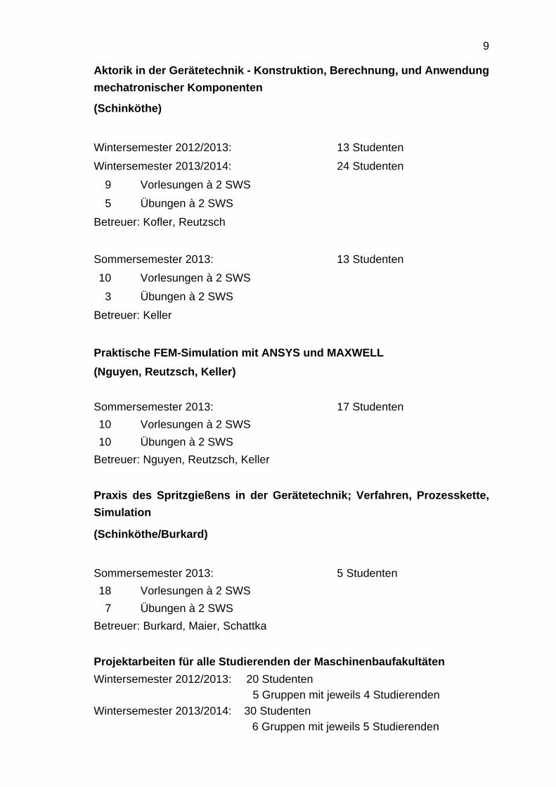
Aktorik in der Gerätetechnik - Konstruktion, Berechnung, und Anwendungmechatronischer Komponenten
(Schinköthe)
Wintersemester 2012/2013: 13 StudentenWintersemester 2013/2014: 24 Studenten
9 Vorlesungen à 2 SWS5 Übungen à 2 SWS
Betreuer: Kofler, Reutzsch
Sommersemester 2013: 13 Studenten10 Vorlesungen à 2 SWS
3 Übungen à 2 SWSBetreuer: Keller
Praktische FEM-Simulation mit ANSYS und MAXWELL(Nguyen, Reutzsch, Keller)
Sommersemester 2013: 17 Studenten10 Vorlesungen à 2 SWS10 Übungen à 2 SWS
Betreuer: Nguyen, Reutzsch, Keller
Praxis des Spritzgießens in der Gerätetechnik; Verfahren, Prozesskette,Simulation
(Schinköthe/Burkard)
Sommersemester 2013: 5 Studenten18 Vorlesungen à 2 SWS
7 Übungen à 2 SWS Betreuer: Burkard, Maier, Schattka
Projektarbeiten für alle Studierenden der MaschinenbaufakultätenWintersemester 2012/2013: 20 Studenten
5 Gruppen mit jeweils 4 StudierendenWintersemester 2013/2014: 30 Studenten
6 Gruppen mit jeweils 5 Studierenden
10
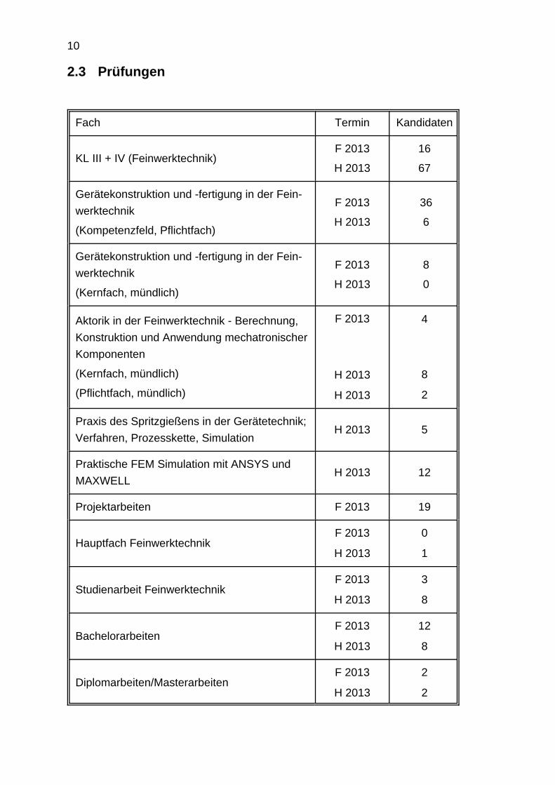
2.3 Prüfungen
Fach Termin Kandidaten
KL III + IV (Feinwerktechnik) F 2013
H 2013
16
67
Gerätekonstruktion und -fertigung in der Fein-werktechnik
(Kompetenzfeld, Pflichtfach)
F 2013
H 2013
36
6
Gerätekonstruktion und -fertigung in der Fein-werktechnik
(Kernfach, mündlich)
F 2013
H 2013
8
0
Aktorik in der Feinwerktechnik - Berechnung,Konstruktion und Anwendung mechatronischerKomponenten
(Kernfach, mündlich)
(Pflichtfach, mündlich)
F 2013
H 2013
H 2013
4
8
2
Praxis des Spritzgießens in der Gerätetechnik;Verfahren, Prozesskette, Simulation
H 2013 5
Praktische FEM Simulation mit ANSYS undMAXWELL
H 2013 12
Projektarbeiten F 2013 19
Hauptfach FeinwerktechnikF 2013
H 2013
0
1
Studienarbeit FeinwerktechnikF 2013
H 2013
3
8
BachelorarbeitenF 2013
H 2013
12
8
Diplomarbeiten/MasterarbeitenF 2013
H 2013
2
2
11
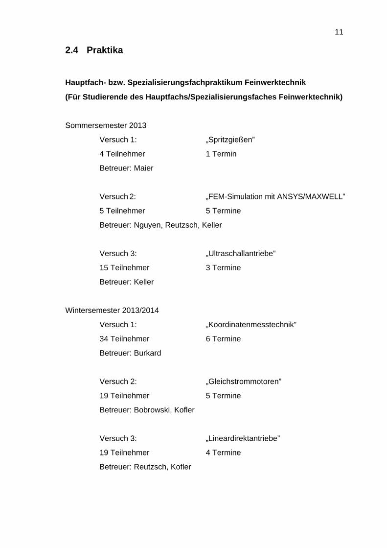
2.4 Praktika
Hauptfach- bzw. Spezialisierungsfachpraktikum Feinwerktechnik
(Für Studierende des Hauptfachs/Spezialisierungsfaches Feinwerktechnik)
Sommersemester 2013
Versuch 1: „Spritzgießen”
4 Teilnehmer 1 Termin
Betreuer: Maier
Versuch 2: „FEM-Simulation mit ANSYS/MAXWELL”
5 Teilnehmer 5 Termine
Betreuer: Nguyen, Reutzsch, Keller
Versuch 3: „Ultraschallantriebe”
15 Teilnehmer 3 Termine
Betreuer: Keller
Wintersemester 2013/2014
Versuch 1: „Koordinatenmesstechnik”
34 Teilnehmer 6 Termine
Betreuer: Burkard
Versuch 2: „Gleichstrommotoren”
19 Teilnehmer 5 Termine
Betreuer: Bobrowski, Kofler
Versuch 3: „Lineardirektantriebe”
19 Teilnehmer 4 Termine
Betreuer: Reutzsch, Kofler
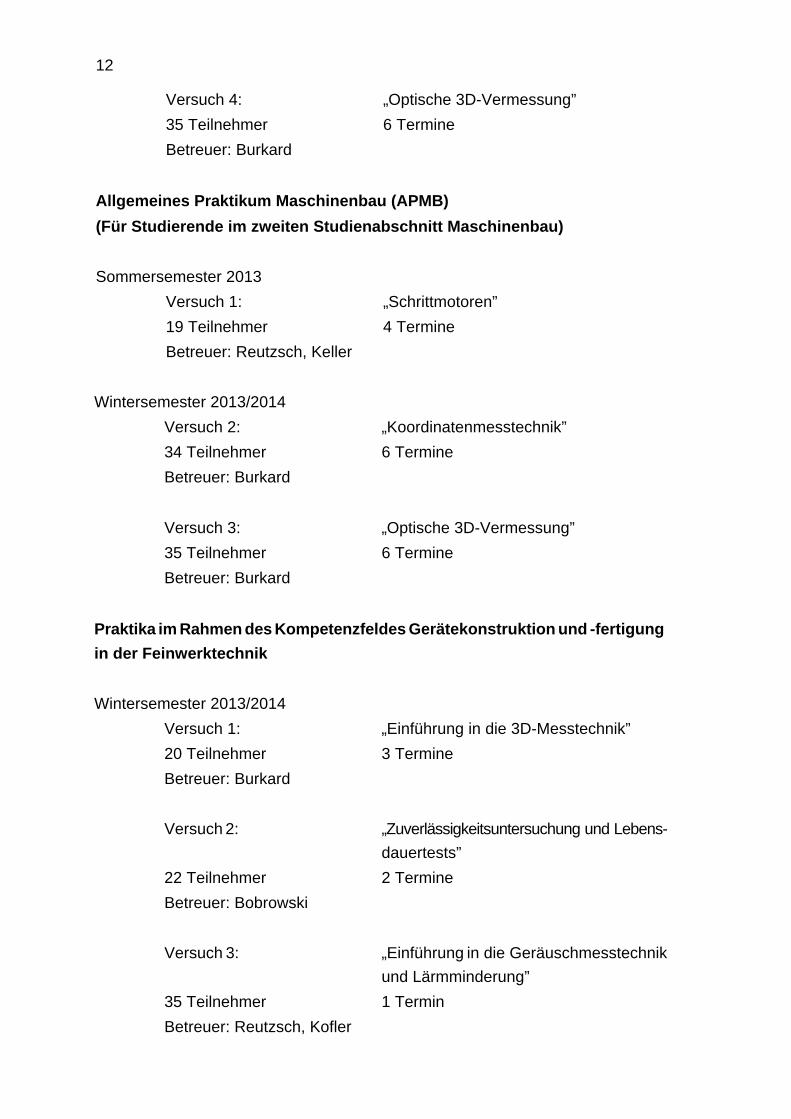
12
Versuch 4: „Optische 3D-Vermessung”35 Teilnehmer 6 TermineBetreuer: Burkard
Allgemeines Praktikum Maschinenbau (APMB)(Für Studierende im zweiten Studienabschnitt Maschinenbau)
Sommersemester 2013Versuch 1: „Schrittmotoren”19 Teilnehmer 4 TermineBetreuer: Reutzsch, Keller
Wintersemester 2013/2014Versuch 2: „Koordinatenmesstechnik”34 Teilnehmer 6 TermineBetreuer: Burkard
Versuch 3: „Optische 3D-Vermessung”35 Teilnehmer 6 TermineBetreuer: Burkard
Praktika im Rahmen des Kompetenzfeldes Gerätekonstruktion und -fertigungin der Feinwerktechnik
Wintersemester 2013/2014Versuch 1: „Einführung in die 3D-Messtechnik” 20 Teilnehmer 3 TermineBetreuer: Burkard
Versuch 2: „Zuverlässigkeitsuntersuchung und Lebens-dauertests”
22 Teilnehmer 2 TermineBetreuer: Bobrowski
Versuch 3: „Einführung in die Geräuschmesstechnikund Lärmminderung”
35 Teilnehmer 1 TerminBetreuer: Reutzsch, Kofler
13
2.5 Projektarbeiten
Wintersemester 2012/2013
31.01.2013 Konstruktion eines Spritzgießwerkzeugs mit Kassetteneinsätzen
31.01.2013 Entwicklung von Regelungskonzepten für einen elektromagneti-schen Schwebeaktor
07.02.2013 Aufbau einer Messvorrichtung zur Bestimmung der Reibwertevon axial belasteten Lagern
07.02.2013 Entwicklung und Inbetriebnahme eines DC-Motorprüfstands
07.02.2013 Funktionsanalyse eines feinwerktechnischen Geräts aus derComputertechnik
Wintersemester 2013/2014
30.01.2014 Aktives Gehörschutzgerät
30.01.2014 Entwicklung und Entwurf von Kinematik-Varianten für Ultraschall-Demonstratoren
30.01.2014 Konstruktion von Spritzgießwerkzeugen für Demonstratorteilefür den Tag der Wissenschaft
06.02.2014 Forschungstrends bei Lineardirektantrieben
06.02.2014 Entwicklung und Aufbau eines Lineardirektantriebs
06.02.2014 Untersuchungen von Alternativen zur Verwendung von kommer-ziellem Filament beim 3D-Druck
14
2.6 Seminar Feinwerktechnik (WS 2012/13 und SS 2013)
10.10.2012 Pricci, Roberto Konstruktion eines Kerns zur Messung derSchwindkräfte für das Spritzgießwerkzeugzur Messung von Entformungskräften
29.11.2012 Jamroz, Ariel Entwicklung einer trajektoriengeplantenVorschubregelung für einen synchronenLineardirektantrieb
29.11.2012 Kauer, Benjamin Messdatenerfassung und Prüfstands-steuerung mit Microcontrollern und USB
06.12.2012 Altdörfer, Denis Untersuchungen zum Verschleiß und zurLebensdauer von Kunststoff-Zahnrädern
06.12.2012 Kofler, Judith Entwicklung einer Mehrgrößenregelung füreinen Schwebeantrieb
10.01.2013 Knelz, Walter Entwicklung eines kombinierten Prüfstandszur Aufnahme von Motorkennlinien
17.01.2013 Beckert, Markus Entwicklung und Konstruktion eines motori-schen Antriebs für den Fokus eines Mikro-skops zur Erweiterung des Schärfentiefe-bereichs
17.01.2013 Schönwiesner, Micha Entwicklung und Konstruktion einerAusgabe- und Selektiervorrichtung fürSpritzgießmaschinen
31.01.2013 Wuschek, Christian Regelung eines elektromagnetischenSchwebeaktors
20.02.2013 Keilbach, Daniel Untersuchung des Einflusses der Ein-spannung auf das Resonanzverhaltenpiezoelektrischer Resonatoren
15
21.02.2013 Lipowsky, Tobias Konstruktion eines Lineardirektantriebs mitstatorseitigen Halbach-Arrays
21.02.2013 Kuczera, Matthias Konzeption, Konstruktion und Simulationeines Tauchspulmotors
14.03.2013 Yuan, Wenbo Simulative Untersuchung des Einflussesder Abmaße von Piezokeramiken auf dieSchwingungsqualität im Resonanzfall andiversen Geometrien
20.03.2013 Benamor, Tasmin Konzeption und Aufbau eines Praktikums-versuchsstands zur Funktionsweise einesbürstenlosen DC-Servomotors
20.03.2013 May, Florian Aufbau eines elektrischen Filters zurKonditionierung der Erregersignale vonUltraschallmotoren
04.04.2013 Dietz, Nina/Kaucher, Ina Entwicklung einer Prüfumgebung für induk-tiv erwärmbare Materialien
11.04.2013 Hetzinger, Stephan Anpassung eines Spritzgießwerkzeugs zurRealisierung einer variablen Formteillänge
11.04.2013 Thiele, Julia Simulationsgestützte Messung der Neukur-ve zylinderförmiger Stahlproben
11.04.2013 Freund, Steffen Regelung eines invertierten Pendels übereinen synchronen Lineardirektantrieb
18.04.2013 Coulon, Lukas Entwicklung von Regelungsstrukturen füreinen elektromagnetischen Schwebeantrieb
02.05.2013 Tajmiri, Babak Thermische Analyse einer induktiv erwärm-ten Klebstoffprobe
23.05.2013 Soetebier, Philipp Entwurf eines neuen Praktikums für dieSpritzgusssimulation mit Moldflow
16
12.09.2013 Schulz, Tobias Entwicklung und Konstruktion einesPrüfstands zur Ermittlung der Reibkraft inAbhängigkeit von der Mikrostruktur derOberfläche
12.09.2013 Liu, E Entwicklung einer Näherungsfunktion fürmagnetische Neukurven
12.09.2013 Maul, Markus Untersuchung zur Nutzung von kosten-günstigen Induktionsgeneratoren aus demKonsumgüterbereich für industrielle Anwen-dungen
26.09.2013 Nußbaumer, Ralf Optimierung eines kombinierten Prüfstandszur Aufnahme von Motorkennlinien
26.09.2013 Karlowitz, Andreas Entwicklung und Bewertung von Rege-lungskonzepten für einen linearen Schwe-beantrieb
26.09.2013 Stegmaier, Tobias Analyse und Ausarbeitung eines rotatori-schen Messprinzips zur Messung derAdhäsionskräfte im Kunststoffspritzguss
Wintersemester 2013/2014 (unvollständig)
10.10.2013 Gharsallaoui, Mohamed Entwicklung und Konstruktion eines moto-risch angetriebenen X-Y-Tisches für dieObjektverschiebung für Mikropanorama-aufnahmen mit einem Mikroskop oder einerMakrooptik
10.10.2013 Riggenmann, Simon Untersuchung von Hard- und Software zuroptischen 3D-Vermessung und Entwicklungeines darauf aufbauenden Praktikumsver-suchs
24.10.2013 Strohmeyr, Simon Entwicklung eines schwebenden Rüttelti-sches mit passivem Läufer

17
24.10.2013 Palenga, Julian Entwicklung eines elektromagnetischenAktors für lineare Schwebeantriebe
21.11.2013 Litwin, Thomas Entwicklung einer sensorlosen Vorschub-steuerung für Lineardirektantriebe
18
3 WISSENSCHAFTLICHE ARBEITEN, STUDIEN-,DIPLOM- UND BACHELORARBEITEN
3.1 Dissertationen
Wibbing, Daniel Wegmess-System für Miniatur-Linearmotoren (SensMiLi).Dissertation, Universität Stuttgart, IKFF, InstitutsberichtNr. 36, 2013
Ulmer, Matthias Einbeziehung des thermischen Teilsystems in dieDimensionierung feinwerktechnischer elektrodynamischerLineardirektantriebe. Dissertation, Universität Stuttgart,IKFF, Institutsbericht Nr. 37, 2014
3.2 Diplomarbeiten am IKFF (WS 2012/13 und SS 2013)
11/2012 Maucher, Andreas Entwicklung und Konstruktion eines RTM-Werkzeugs mit energieeffizienter, vari-othermer Temperierung zur Herstellunggroßflächiger CFK-Bauteile
09/2013 Scheu, Christian Konstruktion eines Prüfstandes zur Ermitt-lung des Einlaufverhaltens von Erstmustern
09/2013 Rupanovic, Christian Entwicklung eines rotatorischen Magnet-lagers mit Lorentzkraft-basierten Aktoren
Wintersemester 2013/2014 (unvollständig)
10/2013 Bayerlein, Philipp Untersuchung von Abkühlvorgängen beiinduktiv beheizten Spritzgusswerkzeugen
11/2013 Schmid, Matthias Auslegung von Kunststoffformwerkzeugenmit energetisch optimierter Temperierung
19
3.3 Bachelorarbeiten am IKFF (WS 2012/13 und SS 2013)
10/2012 Pricci, Roberto Konstruktion eines Kerns zur Messung vonSchwindkräften für das Spritzgießwerkzeugzur Messung von Entformungskräften
11/2012 Kauer, Benjamin Messdatenerfassung und Prüfstands-steuerung mit Mikrocontrollern und USB
11/2012 Schönwiesner, Micha Entwicklung und Konstruktion einer Aus-gabe- und Selektiervorrichtung für Spritz-gießmaschinen
12/2012 Jamroz, Ariel Entwicklung einer trajektoriengeplantenVorschubregelung für einen synchronenLineardirektantrieb
12/2012 Knelz, Walter Entwicklung eines kombinierten Prüfstandszur Aufnahme von Motorkennlinien
12/2012 Altdörfer, Denis Untersuchungen zum Verschleiß und zurLebensdauer von Kunststoff-Zahnrädern
01/2013 Wuschek, Christian Regelung eines elektromagnetischenSchwebeaktors
02/2013 Lipowsky, Tobias Konstruktion eines Lineardirektantriebs mitstatorseitigen Halbach-Arrays
03/2013 May, Florian Aufbau elektrischer Filter zur Konditionie-rung der Erregersignale von Ultraschall-motoren
03/2013 Freund, Steffen Regelung eines invertierten Pendels übereinen synchronen Lineardirektantrieb
20
03/2013 Benamor, Tasmin Konzeption und Aufbau eines Praktikums-versuchsstands zur Funktionsweise einesbürstenlosen DC-Servomotors
05/2013 Soetebier, Philipp Entwurf eines neuen Praktikums für dieSpritzgusssimulation mit Moldflow
07/2013 Gharsallaoui, Mohamed Entwicklung und Konstruktion eines moto-risch angetriebenen X-Y-Tisches für dieObjektverschiebung für Mikropanorama-aufnahmen mit einem Mikroskop oder einerMakrooptik
09/2013 Schulz, Tobias Entwicklung und Konstruktion eines Prüf-stands zur Ermittlung der Reibkraft inAbhängigkeit von der Mikrostruktur derOberfläche
09/2013 Karlowitz, Andreas Entwicklung und Bewertung von Rege-lungskonzepten für einen linearen Schwe-beantrieb
09/2013 Stegmaier, Tobias Analyse und Ausarbeitung eines rotatori-schen Messprinzips zur Messung derAdhäsionskräfte im Kunststoffspritzguss
09/2013 Riggenmann, Simon Untersuchung von Hard- und Software zuroptischen 3D-Vermessung und Entwicklungeines darauf aufbauenden Praktikumsver-suchs
09/2013 Nußbaumer, Ralf Optimierung eines kombinierten Prüfstandszur Aufnahme von Motorkennlinien
21
Wintersemester 2013/2014 (unvollständig)
10/2013 Maul, Markus Untersuchungen zur Nutzung von kosten-günstigen Induktionsgeneratoren aus demKonsumgüterbereich für industrielle Anwen-dungen
10/2013 Litwin, Thomas Entwicklung einer sensorlosen Vorschub-steuerung für Lineardirektantriebe
3.4 Studienarbeiten am IKFF (WS 2012/13 und SS 2013)
02/2013 Kuczera, Matthias Konzeption, Konstruktion und Simulationeines Tauchspulmotors
02/2013 Yuan, Wenbo Simulative Untersuchung des Einflussesder Abmaße von Piezokeramiken auf dieSchwingungsqualität im Resonanzfall andiversen Geometrien
03/2013 Keilbach, Daniel Untersuchung des Einflusses der Ein-spannung auf das Resonanzverhaltenpiezoelektrischer Resonatoren
04/2013 Thiele, Julia Simulationsgestützte Messung der Neukur-ve zylinderförmiger Stahlproben
04/2013 Coulon, Lukas Entwicklung von Regelungsstrukturen füreinen elektromagnetischen Schwebeantrieb
04/2013 Hetzinger, Stephan Anpassung eines Spritzgießwerkzeugs zurRealisierung einer variablen Formteillänge
05/2013 Dietz, Nina / Kaucher, Ina Entwicklung einer Prüfumgebung für induk-tiv erwärmbare Materialien
22
07/2013 Tajmiri, Babak Thermische Analyse einer induktiv erwärm-ten Klebstoffprobe
09/2013 Palenga, Julian Entwicklung eines elektromagnetischenAktors für lineare Schwebeantriebe
09/2013 Liu, E Entwicklung einer Näherungsfunktion fürmagnetische Neukurven
Wintersemester 2013/2014 (unvollständig)
10/2013 Strohmeyr, Simon Entwicklung eines schwebenden Rüttelti-sches mit passivem Läufer
3.5 Preise
Dipl.-Ing. Judith Kofler Gustav-Magenwirth-Preis
23
4 ARBEITSGEBIETE DER WISSENSCHAFTLICHENMITARBEITER
4.1 Aktorik
Engel, M. Lehre: Betreuung der Bachelorübungen in KL 3/4 in Form von Gruppen-übungen. Korrektur von Klausuraufgaben.Betreuung einer Bachelor-Projektarbeit.Forschung:Wirbelstrom- und Hystereseverluste in Linearmotoren.Simulation von Wirbelstromverlusten und Hystereseverlusten inRückschlussmaterialien.Konzepte zur Reduzierung der Verlustkomponenten.Messungen am Prüfstand zur Verlustmessung in Materialien.Aufnahme von Kennlinien.
Keller, B. Lehre:Betreuung von Gruppenübungen in KL 3/4.Ausarbeitung von Aufgabenstellungen für Übungs- und Prüfungs-aufgaben sowie deren Korrektur.Überarbeitung und Durchführung der Vortragsübung„Getriebedimensionierung/-gestaltung” in KL 3/4.
Durchführung der Vortragsübung „Ultraschallantriebe” imHauptfach Aktorik.Durchführung der Vorlesung und Übung „Praktische FEM-Simulation mit MAXWELL und ANSYS” und Ausarbeitung vonAufgabenstellungen für Prüfungsaufgaben sowie deren Korrektur.Durchführung des Hauptfachpraktikums „Ultraschallantriebe”. Betreuung von Projekt-, Bachelor-, Master-, Studien- undDiplomarbeiten.Forschung:Entwicklung von piezoelektrischen Motoren mit Schwerpunkt inSchwingungsuntersuchungen von Mehrkoordinaten-Ultraschall-motoren.
24
Industrieprojekte.Sonstiges: PC-Administration.
Kofler, J. Lehre:Betreuung der Vordiplomsübungen in KL 3/4, Testatgruppen.Vortragsübung und Vorlesung KL 3/4 zur Lagerberechnung.Durchführung der Praktika „Lineardirektantriebe” sowie „Gleich-strommotoren” und „Geräuschmesstechnik”.Erstellen der Übung zur Lagerauswahl des Testats „Welle-Lager”.Betreuung von Bachelor- und Projektarbeiten.Industrieprojekte.Sonstiges: PC-Administration.
Kreuzer, D. Forschung:Entwicklung von Lineardirektantrieben und FEM-Simulation.
Reutzsch, B. Lehre:Vortragsübung und Vorlesung KL 3/4 zum Themenkomplex„Welle-Lager” und „Kupplungen”.Vorlesung zum Themenkomplex „Ansteuerung und Regelung vonLineardirektantrieben” in „Aktorik in der Feinwerktechnik”.Vorlesung „Praktische FEM-Simulation mit ANSYS und MAX-WELL”.Durchführung der Praktika „Lineardirektantriebe” sowie „Schritt-motoren” und „Geräuschmesstechnik”.Betreuung der Vordiplomsübungen in KL 3/4, Testatgruppen. Organisation des Übungskomplexes „Welle-Lager” und „Kupp-lungen”.Betreuung von Bachelor-, Studien- und Diplomarbeiten.Forschung:Forschungsschwerpunkt: Magnetschwebetechnik für feinwerktech-nische Antriebe.Simulative Auslegung und Konstruktion sowie Regelung undAnsteuerung magnetischer Führungen und linearer Direktantriebe.Industrieprojekte.Sonstiges: PC-Administration.
25
4.2 Spritzgießen
Akkaya, H. Lehre:Betreuung der Vordiplomsübungen in KL 3/4, Testatgruppen.Forschung:Modellbildung, Simulation und Auslegung von induktivenHeizsystemen.Industrieprojekte.
Burkard, E. Untersuchung des Einflusses von Werkzeugbeschichtungen aufdie Entformungskraft bei Spritzgussbauteilen aus Thermo-plastwerkstoffen.Bearbeitung von Industrieaufträgen.Betreuung der Studenten im B. Sc., M. Sc. und Hauptdiplom.Betreuung von Vorlesungen und Übungen im B. Sc., M. Sc. undHauptdiplom.Organisation des Konstruktionslehrewettbewerbs.Betreuung und Durchführung der Vorlesung „Praxis desSpritzgießens in der Gerätetechnik”.Betreuung der 3D-Messmaschinen und Vermessung vonWerkstücken und der Praktika zur 3D-Messtechnik.Administration und Wartung der UNIX/Linux-Rechner und desInstitutsnetzes.Stundenplanbeauftragter und Studiengangsmanager für den M.Sc. Maschinenbau/Mikrotechnik, Gerätetechnik und TechnischeOptik.
Maier, M. Lehre:Betreuung der Vordiplomsübungen in KL 3/4, Testatgruppen.Durchführung des Hauptfachpraktikums „Spritzgießen”.Betreuung von Bachelor- und Studienarbeiten.Forschung:Weiterentwicklung von FEM-Simulationsmodellen zur quantitativenBeschreibung von Induktionserwärmung unter Berücksichtigungdes Generatorschwingkreises.Einsatz von Hochleistungskeramiken in induktiv beheiztenSpritzgusswerkzeugen.Industrieprojekte.
26
Maucher, A. Lehre:Betreuung der Vordiplomsübungen in KL 3/4, Testatgruppen.Ausarbeitung von Aufgabenstellungen für Übungs- und Klausur-aufgaben sowie deren Korrektur.Durchführung der Vortragsübung „Koppelgetriebe” im VordiplomKL 3/4.Betreuung einer Projektarbeit und einer Diplomarbeit.Forschung:Untersuchung des Abkühlverhaltens von induktiv beheiztenSpritzgusswerkzeugen.Simulative Untersuchung des Strömungsverhaltens vonKühlflüssigkeiten in Spritzgusswerkzeugen im Hinblick aufunterschiedliche Einströmarten mittels CFD.Entwicklung von Simulationsmodellen zur Untersuchung desEnergiehaushalts bei Phasenübergängen von Fluiden inKühlkreisläufen.Sonstiges: Netzwerk-Administration.
Nguyen, M. Lehre:Betreuung der Vordiplomsübungen in KL 3/4 in Form vonGruppenübungen. Korrektur von Klausuraufgaben.Durchführung des Hauptfachpraktikums „Praktische FEM-Simulation mit ANSYS und MAXWELL”.Betreuung von Studienarbeiten.Forschung: Aufbau und Inbetriebnahme eines Spritzgusswerkzeugs zurvariothermen Herstellung kunststoffgebundener Dauermag-net-Probekörper.Durchführung und Auswertung von Versuchen zur variothermenMessung der Materialeigenschaften kunststoffgebundenerDauermagnete.Konstruktion eines Werkzeugs und einer Messeinrichtung zurVerifikation des entwickelten Simulationssystems.
Retzbach, A. Lehre:Betreuung der Vordiplomsübungen in KL 3/4, Testatgruppen.Betreuung von Bachelor- und Studienarbeiten.
27
Forschung:Entwicklung neuer Ansätze zur Vorkonditionierung partikelgefüllterKlebstoffe.Untersuchungen zu Einflussfaktoren bei der induktiven Erwärmungpartikelgefüllter Klebstoffe.Modellbildung, Simulation und Auslegung von induktivenHeizsystemen.
Schattka, G. Lehre:Betreuung der Vordiplomsübungen in KL 3/4, Testatgruppen.Korrektur von Prüfungsaufgaben in KL 3/4.Betreuung von Bachelor- und Studienarbeiten. Organisation des Konstruktionslehrewettbewerbs.Forschung:Konstruktion eines Spritzgusswerkzeugs zur Ermittlung derAdhäsionskräfte verschiedener Kunststoff-Beschichtungs-Paarungen beim Spritzgießen.Messung mehrerer Entformungskräfte unterschiedlicherKunststoff-Beschichtungs-Paarungen.Ansätze zur theoretischen Ermittlung der Adhäsionskräfte imKunststoffspritzguss.
4.3 Zuverlässigkeitstechnik
Bobrowski, S. Lehre:Durchführung der Vortragsübungen „Zuverlässigkeit mechatro-nischer Systeme” im Rahmen der Vorlesung Gerätekonstruktionund -fertigung in der Feinwerktechnik im Masterstudium.Konzeption von Übungsaufgaben und Prüfungsaufgaben zurZuverlässigkeit.Durchführung des Praktikums „Gleichstrommotoren”.Betreuung von Gruppenübungen in KL 3/4, Korrektur vonÜbungsaufgaben.Durchführung des Praktikums „Zuverlässigkeitsuntersuchung undLebensdauertests” für die Vorlesung Gerätekonstruktion und-fertigung in der Feinwerktechnik.Betreuung von Studienarbeiten und einer Bachelor-Projektarbeit.
28
Forschung:Mitarbeit im DFG-Projekt „Zuverlässigkeitsprognose mechatro-nischer Systeme mit Hilfe statistischer Modelle am Beispielfeinwerktechnischer Komponenten” (GZ: Je 162/10-1, Schi457/12-1)Systemzuverlässigkeit in frühen Entwicklungsphasen, Zuverlässig-keit von elektromechanischen/mechatronischen Systemen amBeispiel feinwerktechnischer Antriebe/Aktorik, Zuverlässigkeits-prognose.Aufbau und Betrieb von Dauerlaufprüfständen für mechatronischeSysteme (rotatorische Kleinantriebe), Dokumentation.Vermessung von Prüflingen.Entwicklung von Methoden zur Zuverlässigkeitsermittlung undmathematischen Zuverlässigkeitsmodellen (Kooperation mit demIAMS, Institut für Angewandte Mathematik und Statistik derUniversität Hohenheim).Industrieprojekte. Sonstiges: Ansprechpartner für Literaturrecherchen.
29
5 ÖFFENTLICHKEITSARBEIT
5.1 Veröffentlichungen
Artikel oder Tagungsbeiträge:
Bobrowski, S.; Döring, M.; Jensen, U.; Schinköthe, W.: Zuverlässigkeitsprognosemit dem Cox-Proportional-Hazards-Modell. Vortrag Stuttgarter Symposium fürProduktentwicklung 2013, Stuttgart 20.06.2013.
Bobrowski, S.; Schinköthe, W., Döring, M.; Jensen, U.: Reliability Prediction forMechatronic Drive Systems. 9. GMM/ETG-Fachtagung Innovative Klein- undMikroantriebstechnik 2013, Nürnberg 19./20.09.2013.
Engel, M.; Schinköthe, W.: Eddy current and hysteresis losses in high dynamic direct-drive linear motors for manufacturing systems. Postervortrag GSaME Jahrestagung2013, Stuttgart 21.03.2013.
Keller, B.; Schinköthe, W.: Multi-Degree-of-Freedom Ultrasonic Motors using Rotation-Symmetric Piezoelectric Vault Geometries. 9. GMM/ETG-Fachtagung Innovative Klein-und Mikroantriebstechnik 2013, Nürnberg 19./20.09.2013.
Landfried, R.; Gadow, R.; Maier, M.; Schinköthe, W.: Spritzgusswerkzeuge mitkeramischen Formbereichen zur prozessintegrierten induktiven Erwärmung vonEinlegeteilen. Vortrag und Tagungsbandbeitrag, 23. Stuttgarter Kunststoffkolloquium,06./07.03.2013
Maier, M.; Retzbach, A.; Schinköthe, W.: Induktionserwärmung für die Kunst-stoffverarbeitung - Ganzheitliche Modellbildung. Plastverarbeiter. Jahrgang 64(2013)H10; S. 134-137.
Maier, M.; Schinköthe, W.: Anwendungspotential der Induktionserwärmung in derKunststoffverarbeitung. Fachbeitrag Forschungsreport für den Maschinenbau in Baden-Württemberg WS 2013/14, Public Verlagsgesellschaft und Anzeigenagentur mbH,Bingen, 2013, S. 24-27.
30
Nguyen, M.; Schinköthe, W.: Characterization of magnetic injection molding processes.Postervortrag GSaME Jahrestagung 2013, Stuttgart 21.03.2013.
Nguyen, M.: Messung magnetischer Materialdaten. Posterveröffentlichung am IKFF,29.05.2013.
Reutzsch, B.; Schinköthe, W.: Magnetic Levitation System for Linear Direct Drivesbased on Lorentz Forces. 9. GMM/ETG-Fachtagung Innovative Klein- undMikroantriebstechnik 2013, Nürnberg 19./20.09.2013.
Schattka, G.; Burkard, E.; Schinköthe, W.: Entformungskraftuntersuchungen beimSpritzgießen - Neuer messtechnischer Ansatz zur Ermittlung der Adhäsions- undGleitreibungskräfte bei der Entformung. Vortrag und Tagungsbandbeitrag. 23.Stuttgarter Kunststoffkolloquium, 06./07.03.2013.
Schinköthe, W.: Induktive Temperierung zur Effizienzsteigerung beim Spritzgießen.Vortrag GSaME Jahrestagung 2013, Stuttgart 21.03.2013.
Patente:Maier, M.; Burkard, E.; Zimmermann, T.; Schinköthe, W.: Vorrichtung zur Verbindungzweier elektrischer Leitungen. DE 10 2011 086 212, Patent angemeldet am11.11.2011, erteilt mit Wirkung zum 01.08.2013.
Retzbach, A.; Schinköthe, W.; Wellmann, S.; Dura, G.: Optimierung der Energieein-bringung in partikelgefüllte Klebstoffe bei induktiver Erwärmung. Erfindungsmeldungan Uni Stuttgart.
5.2 Gremienarbeit
Prof. Dr.-Ing. Wolfgang Schinköthe:Mitglied des Wissenschaftlichen Beirates der Zeitschrift Mechatronik F&M Mitglied im Kuratorium der Gustav-Magenwirth-Stiftung, Bad UrachIn der VDE/VDI-Gesellschaft Mikroelektronik, Mikro- und Feinwerktechnik (GMM):Mitglied des Beirats der GMMFachbereichsleiter Fachbereich 3 Feinwerktechnik und MechatronikMitglied des Fachausschusses 3.3 Elektrische Geräte- und StellantriebeProgrammausschuss Tagung Innovative Klein- und Mikroantriebstechnik, Nürnberg.
31
5.3 Tag der Wissenschaft
1 Maschine, 6 Taschen, 15 Kugeln - 2 Maschinen, 6 Taschen, 30 Kugeln...Es soll eine Maschine entwickelt werden, die Billardkugeln einlocht.
So einfach lautete die Aufgaben-stellung des diesjährigen Konstruk-tionswettbewerbs des Instituts fürKonstruktion und Fertigung in derFeinwerktechnik der UniversitätStuttgart, der dieses Jahr zum 21.Mal ausgetragen wurde. Wie in denvergangenen Jahren waren einigeRandbedingungen zu beachten.Dabei waren die limitierte Größe der Maschinen beim Start und die Vorgaben zurEnergieversorgung wohl die stärksten Einschränkungen.
In der Vorrunde mussten die Maschinen einfach möglichst viele Kugeln in die Tascheneinlochen. Alle Maschinen, die mindestens eine Kugel einlochten, nahmen am zweitenTeil des Wettbewerbs teil. Nun mussten sie gegeneinander antreten und konntensowohl in der eigenen, als auch in der gegnerischen Hälfte Kugeln einlochen. Dabeizählten die beim Gegner eingelochten Kugeln doppelt.
Wer selbst schon Poolbillard gespielt hat, kennt die Tücken des Spiels und nur knappan der Tasche vorbei gespielte Kugeln, und genau mit diesen Problemen musstenauch die studentischen Maschinen kämpfen, die gleichzeitig Spieler, Queue undSpielkugel waren.
Die Teilnehmergruppen konnten beim Wettbewerb erleben, dass die Umsetzung vontheoretischem Wissen in eine praktisch funktionierende, kleine Maschine nicht ganzso einfach ist, wie sie wohl am Anfang gedacht hatten. Schon die vermeintlich einfacheAufgabe, auf einer freien Fläche wenige Meter geradeaus zu fahren und dannrückwärts wieder präzise zum Ausgangspunkt zu kommen, ist für eine kleine Maschineohne aufwendige Sensorik nicht unbedingt einfach zu bewältigen. Umgekehrt ist esaber auch nicht einfach, innerhalb nur weniger Wochen eine mit einem Mikrocontrollergesteuerte Maschine mit zugehöriger Software und der notwendigen Antriebstechnikzu entwickeln und aufzubauen. Am Ende standen zwei Maschinen im Finale, die beideauf dem gleichen Grundprinzip basierten und die Aufgabe rein elektromechanischlösten.
32
Für die Teilnehmer und die Zuschauer war besonders der zweite Teil des Wettkampfsspannend, da sich hier zeigte, welches Grundprinzip die beste Lösung für denBillardwettkampf war und wessen Lösung am zuverlässigsten die Kugeln einlochte.
Ein besonderer Dank gilt den folgenden Firmen, die den Wettbewerb teilweise schonseit vielen Jahren unterstützen:
ARBURG GmbH & Co, Audi AG, Bilz Werkzeugfabrik GmbH & Co. KG, Carl HanserVerlag GmbH & Co, Christian Bürkert Stiftung gGmbH, Dr. Fritz Faulhaber GmbH& Co. KG, Dr. Ing. Paul Christiani GmbH & Co KG, G. Ulmer Automation GmbH,Hauni Maschinenbau AG, Kendrion GmbH, SEW-EURODRIVE GmbH & Co KG,Springer Verlag GmbH und Verlag Europa-Lehrmittel Nourney Vollmer GmbH & Co.KG.
Ergebnisse:
1. Platz: André Färber, Lorenz Görne, Daniel Haas, Sven Schuster.
2. Platz: Sebastian Held, Felix Kurz, Jonas Manz, Alena Modic.
3. Platz: Andreas Gruber, Thomas Labitzke, Peter Maderthaner, Mike Schneider.
33
6 KONGRESSE, TAGUNGEN UND MESSEN
Prof. Schinköthe, W.:
! 23. Stuttgarter Kunststoffkolloquium, 06./07.03.2013
! Jahrestagung der GSaME Graduate School of advanced ManufacturingEngineering, Stuttgart, 21.03.2013
! Stuttgarter Symposium für Produktentwicklung 2013, 20.06.2013
! 9. GMM/ETG-Fachtagung Innovative Klein- und Mikroantriebstechnik,Nürnberg, 19./20.09.2013
! Kendrion Symposium, Villingen-Schwenningen, 07.11.2013
Akkaya, H.:
! ARBURG Technologietage, Loßburg, 13.03.2013
Bobrowski, S.:
! Tagung „Technische Zuverlässigkeit”, Leonberg, 23./24.04.2013.
! VDI Gremium FA825 thermoplastische Zahnräder (Richtlinie VDI 2736),Stuttgart, IKFF, 05.02.2013, Bubikon, 05.06.2013
! Stuttgarter Symposium für Produktentwicklung 2013, 20.06.2013
! 9. GMM/ETG-Fachtagung Innovative Klein- und Mikroantriebstechnik,Nürnberg, 19./20.09.2013
Burkard, E.:
! 23. Stuttgarter Kunststoffkolloquium, 06./07.03.2013
! ARBURG Technologietage, Loßburg, 13.03.2013
Engel, M.:
! Jahrestagung der GSaME Graduate School of advanced ManufacturingEngineering, Stuttgart, 21.03.2013
! 5. CADFEM EM-Symposium 2013, Würzburg, 13.11.2013
Keller, B.:
! 9. GMM/ETG-Fachtagung Innovative Klein- und Mikroantriebstechnik,Nürnberg, 19./20.09.2013
34
Kofler, J.:
! 9. GMM/ETG-Fachtagung Innovative Klein- und Mikroantriebstechnik,Nürnberg, 19./20.09.2013
Maier, M.:
! ARBURG Technologietage, Loßburg, 13.03.2013
! Composites-Europe, Stuttgart, 18.09.2013
! K-Messe, Düsseldorf, 22.10.2013
! CADFEM EM-Symposium, Würzburg, 13.11.2013
Maucher, A.:
! ARBURG Technologietage, Loßburg, 13.03.2013
Nguyen, M.:
! Jahrestagung der GSaME Graduate School of advanced ManufacturingEngineering, Stuttgart, 21.03.2013
! Kendrion Symposium, Villingen-Schwenningen, 07.11.2013
! CADFEM EM-Symposium, Würzburg, 13.11.2013
Retzbach, A.:
! K-Messe, Düsseldorf, 18.10.2013
! CADFEM EM-Symposium, Würzburg, 13.11.2013
Reutzsch, B.:
! 9. GMM/ETG-Fachtagung Innovative Klein- und Mikroantriebstechnik,Nürnberg, 19./20.09.2013
Schattka, G.:
! ARBURG Technologietage, Loßburg, 13.03.2013
35
7 WERKSTATTBERICHT
Mit der Fertigung von Linearmotoren, Linearmotorprüfständen, Spritzgussformenund Formeinsätzen sowie Bauteilen und Baugruppen für Versuche im Rahmen vonstudentischen Arbeiten und Dissertationen war die Institutswerkstatt auch in diesemBerichtsjahr wieder vollständig ausgelastet.
8 ANHANG - Ausgewählte Veröffentlichungen
In diesem Jahr hängen wir exemplarisch zwei Veröffentlichungen aus dem BereichAktorik an, einerseits einen Beitrag zu neuartigen piezoelektrischen Mehrkoordinaten-antrieben mit Gewölbegeometrien als Erregerstruktur und andererseits einen Beitragzu Lineardirektantrieben mit integrierter Magnetführung:
Keller, B.; Schinköthe, W.: Multi-Degree-of-Freedom Ultrasonic Motors using Rotation-Symmetric Piezoelectric Vault Geometries. 9. GMM/ETG-Fachtagung Innovative Klein-und Mikroantriebstechnik 2013, Nürnberg 19./20.09.2013.
Reutzsch, B.; Schinköthe, W.: Magnetic Levitation System for Linear Direct Drivesbased on Lorentz Forces. 9. GMM/ETG-Fachtagung Innovative Klein- undMikroantriebstechnik 2013, Nürnberg 19./20.09.2013.

Multi-degree-of-freedom ultrasonic motors using rotation-symmetric piezoelectric vault geometries Dipl.-Ing. Bastian Keller, Prof. Dr.-Ing. Wolfgang Schinkoethe, University of Stuttgart, Institute of Design and Production in Precision Engineering, Stuttgart, Germany Abstract The multi-degree-of-freedom (multi-DOF) ultrasonic motors described in this paper use one rotation-symmetric vault geometry (e.g. a hemispherical shell) made of piezoelectric material to provide three dimensional (3-D) trajectories on the top of this vault shaped vibrator. There with spherical, planar or a combination of linear and rotatory drives can be driven in several directions by a friction contact. The 3-D trajectories are generated by superposition of one horizontal and one vertical eigenmode. The horizontal eigenmode causes the vibrators top to move in several horizontal directions and the vertical eigenmode causes a movement in the vertical direction. So the superposition of these movements results in 3-D trajectories on the top of the vault vibrator. The coincidence of the resonance frequencies of the used eigenmodes and the fixing of the vibrator are key issues that have to be incorporated by the development of such motors. Further-more, the excitation structure - specified by the electrode division that can be ordered circular segmented on the vibrator – looms large, too. There are different types of vault shapes (e.g. bell shells) and excitation techniques such multi-DOF ultrasonic motors can be build from. Out of this arises a multiplicity of opportunities to realize several variants of this type of motor. A prototype vibrator, composed of a hemispherical shell glued on a metal disk, will be described at the end of this paper that proves to be promising to use vault shaped vibrators for the development of multi-DOF ultrasonic motors.
1 Multi-DOF ultrasonic motors Multi-DOF ultrasonic motors operate like other ultrasonic motors. They use solid vibrations to generate trajectories that drive a rotor or linear slider by friction contacts [1]. Especially, multi-DOF motors can drive spherical rotors or planar sliders with two or more degrees of freedom.
1.1 Drive side variants of multi-DOF mo-tors
In addition to conventional one dimensional (1-D) rotors or linear sliders, multi-DOF motors can drive other forms of drive side movements. Figure 1 shows three examples of how such multi-dimensional movements can be ac-complished. Furthermore, there are other variants that re-sult from combinations of several translational and/or ro-tational movements.
z
y
x
y
x
z
y
x
z
2-D linear/rotatory (x-α)
3-D spherical( - -α β γ)
3-D planar(x- -z)β
Figure 1 Examples of 2-D and 3-D drive side variants
When designing multi-DOF actuators the dimension of the trajectories plays a major role. These determine the direction of the drive side motion by the friction contact.
y
x
z x-z plane 2-D trajectory
x-y plane 2-D trajectory
y-z plane 2-D trajectory
y
x
z x-y plane 2-D trajectory
2-D trajectory
1-D drive side 2-D/3-D drive side
3-D trajectory
Figure 2 Dimensions of trajectories Two dimensional (2-D) trajectories arise from a phase-shifted superposition of two motions with different direc-tions. 3-D trajectories are generated by the superposition of three phase-shifted motions with different directions, respectively by shaping of 2-D plane trajectories with several orientations, see Figure 2. Thus, drive side movements of at least two degrees of freedom are possi-ble.
1.2 Established designs of multi-DOF mo-tors
The vibrators of common ultrasonic vibrators generate elliptical 2-D trajectories, which allow 1-D drive side movements only [2] [3]. In order to achieve multi-dimensional drive side movements with such vibrators,
[4] and [5] use spatially displaced vibrators that are ar-ranged with different orientations, cf. Figure 3.
z
y
x
Vibrators with2-D trajektories
Figure 3 Example of a spherical drive side with three spatially arranged vibrators. In the past few years, various multi-DOF ultrasonic mo-tors have been developed that use a single vibrator form-ing 3-D trajectories [6]-[10]. These motors are all made of so-called composite vibrators. This means they use a spe-cial shaped vibrator made of metal, which is excited by multiple displaced ordered piezo-elements, to vibrate it in different directions. The operating principle is the same for all these motors: A frictional contact at one front side or in the middle of the vibrator is used to form 3-D trajec-tories that allow driving multi-DOF drive side variants with at least two degrees of freedom. In [6] and [7] one vibrator drives 3-D spherical drive sides. In contrast, [8] and [9] describe planar 2-D drive side movements with one vibrator. In order to achieve further degrees-of-freedom multiple vibrators can be arranged spatially dis-placed. For that purpose Figure 4 shows a planar array of multiple vibrators [10]. In this connection the vibrators are embedded into the drive side that slides over a base surface. The translations (x and y) come about if the ver-tical standing 2-D trajectories of all vibrators have the same orientation. The rotation (β) takes place if the orien-tations of the vertical standing 2-D trajectories are skewed each other; for example if the orientation of each trajec-tory is perpendicular to the rotation point.
3D-planar(x- -zβ )
y
z x
1
2
3
4
Figure 4 Multiple in a plane arranged vibrators. 1. Vibrator, 2. Drive side, 3. Base surface, 4. Friction con-tact
2 Multi-DOF motors with rotation-symmetric piezoelectric vault vi-brators
The piezoelectric motor variants described here are based on the same operating principle as the motors with the composite vibrators described above. In contrast, how-ever, a composite vibrator is not used here, but rather a rotation symmetric vault geometry (e.g. a hemispherical shell) made of piezoelectric material with radial polarisa-tion and electrodes on the inner and outer surface to pro-vide 3-D trajectories on the top of the vault vibrator. The 3-D trajectories are formed by superposition of a ver-tical and a horizontal eigenmode, wherein the horizontal eigenmode can be excited in multiple directions (for ex-ample in the direction of the x- and z-axis), see Figure 5. The top of the vault vibrator swings in the same direction as the eigenmodes are reflected in, whereby 3-D trajecto-ries or 2-D trajectories with different orientations can be generated.
y
x
y
z x
b) First horizontal eigenmode
y
x
a) First vertical eigenmode
z x
y
Half-section view Isometric view
Figure 5 Examples of a vertical and a horizontal eigen-mode of a hemispherical shell A phase-shifted excitation of a vertical and a horizontal eigenmode generates plane, vertical standing trajectories (ex. x-y or y-z plane 2-D trajectories). In order to circulate the trajectories evenly, the frequency of all vibrations has to be identical. Because maximum amplitudes arise if both eigenmodes are operating in reso-nance, the coincidence of both eigenfrequencies is desir-able.
2.1 Excitation structure and techniques In view of the excitability of horizontal and vertical eigenmodes the excitation structure looms large. This is specified by patterning the electrodes on the outer and/or inner surface of the vault vibrator. There are many differ-ent possibilities for partitioning the electrodes. When selecting the partition of the electrodes, it must be consid-
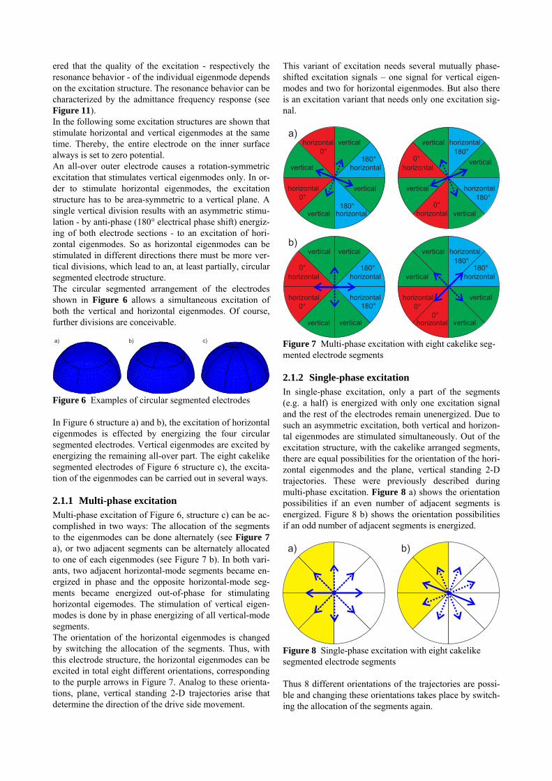
ered that the quality of the excitation - respectively the resonance behavior - of the individual eigenmode depends on the excitation structure. The resonance behavior can be characterized by the admittance frequency response (see Figure 11). In the following some excitation structures are shown that stimulate horizontal and vertical eigenmodes at the same time. Thereby, the entire electrode on the inner surface always is set to zero potential. An all-over outer electrode causes a rotation-symmetric excitation that stimulates vertical eigenmodes only. In or-der to stimulate horizontal eigenmodes, the excitation structure has to be area-symmetric to a vertical plane. A single vertical division results with an asymmetric stimu-lation - by anti-phase (180° electrical phase shift) energiz-ing of both electrode sections - to an excitation of hori-zontal eigenmodes. So as horizontal eigenmodes can be stimulated in different directions there must be more ver-tical divisions, which lead to an, at least partially, circular segmented electrode structure. The circular segmented arrangement of the electrodes shown in Figure 6 allows a simultaneous excitation of both the vertical and horizontal eigenmodes. Of course, further divisions are conceivable. a) b) c)
Figure 6 Examples of circular segmented electrodes In Figure 6 structure a) and b), the excitation of horizontal eigenmodes is effected by energizing the four circular segmented electrodes. Vertical eigenmodes are excited by energizing the remaining all-over part. The eight cakelike segmented electrodes of Figure 6 structure c), the excita-tion of the eigenmodes can be carried out in several ways.
2.1.1 Multi-phase excitation Multi-phase excitation of Figure 6, structure c) can be ac-complished in two ways: The allocation of the segments to the eigenmodes can be done alternately (see Figure 7 a), or two adjacent segments can be alternately allocated to one of each eigenmodes (see Figure 7 b). In both vari-ants, two adjacent horizontal-mode segments became en-ergized in phase and the opposite horizontal-mode seg-ments became energized out-of-phase for stimulating horizontal eigemodes. The stimulation of vertical eigen-modes is done by in phase energizing of all vertical-mode segments. The orientation of the horizontal eigenmodes is changed by switching the allocation of the segments. Thus, with this electrode structure, the horizontal eigenmodes can be excited in total eight different orientations, corresponding to the purple arrows in Figure 7. Analog to these orienta-tions, plane, vertical standing 2-D trajectories arise that determine the direction of the drive side movement.
This variant of excitation needs several mutually phase-shifted excitation signals – one signal for vertical eigen-modes and two for horizontal eigenmodes. But also there is an excitation variant that needs only one excitation sig-nal.
vertical
horizontal horizontal
horizontalhorizontal
vertical
verticalvertical
vertical
horizontal
horizontal
horizontal
vertical
vertical
b)
vertical
horizontal
horizontal
horizontal
horizontal
vertical
vertical
vertical
vertical
horizontal
horizontalvertical
vertical
a)
horizontal
vertical
horizontal
0°
0°
180°
180°
0°
0°180°
180°
horizontal
180°180°
vertical
0°
0° 180°
180°
0°
0°
Figure 7 Multi-phase excitation with eight cakelike seg-mented electrode segments
2.1.2 Single-phase excitation In single-phase excitation, only a part of the segments (e.g. a half) is energized with only one excitation signal and the rest of the electrodes remain unenergized. Due to such an asymmetric excitation, both vertical and horizon-tal eigenmodes are stimulated simultaneously. Out of the excitation structure, with the cakelike arranged segments, there are equal possibilities for the orientation of the hori-zontal eigenmodes and the plane, vertical standing 2-D trajectories. These were previously described during multi-phase excitation. Figure 8 a) shows the orientation possibilities if an even number of adjacent segments is energized. Figure 8 b) shows the orientation possibilities if an odd number of adjacent segments is energized. a) b)
Figure 8 Single-phase excitation with eight cakelike segmented electrode segments Thus 8 different orientations of the trajectories are possi-ble and changing these orientations takes place by switch-ing the allocation of the segments again.
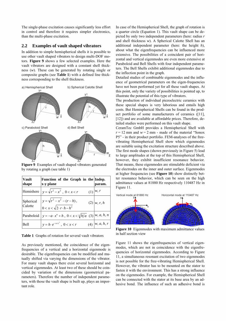
The single-phase excitation causes significantly less effort in control and therefore it requires simpler electronics, than the multi-phase excitation.
2.2 Examples of vault shaped vibrators In addition to simple hemispherical shells it is possible to use other vault shaped vibrators to design multi-DOF mo-tors. Figure 9 shows a few selected examples. Here the vault vibrators are designed with a constant shell thick-ness (w). These can be generated by rotating single or composite graphs (see Table 1) with a defined line thick-ness corresponding to the shell thickness.
z
y
xw
z
y
x
h
w
r
z
y
x
h
w
z
y
x
h
wr
a) Hemispherical Shell b) Spherical Calotte Shell
c) Paraboloid Shell d) Bell Shell
r
Figure 9 Examples of vault shaped vibrators generated by rotating a graph (see table 1)
Vault shape
Function of the Graph in the x-y plane
Indep. param.
Hemishere 22 xry , rx 0 (1) w, r
Spherical Calotte
)(22 hrxry ,
220 hhrx
(2) w, r, h
Paraboloid hxay n , n0 ahx (3) w, a, h, n
Bell 2xa ehy , rx 0 (4) w, a, h, r
Table 1 Graphs of rotation for several vault vibrators As previously mentioned, the coincidence of the eigen-frequencies of a vertical and a horizontal eigenmode is desirable. The eigenfrequencies can be modified and mu-tually shifted via varying the dimensions of the vibrator. For many vault shapes there exist several horizontal and vertical eigenmodes. At least two of these should be coin-cided by variation of the dimensions (geometrical pa-rameters). Therefore the number of independent parame-ters, with those the vault shape is built up, plays an impor-tant role.
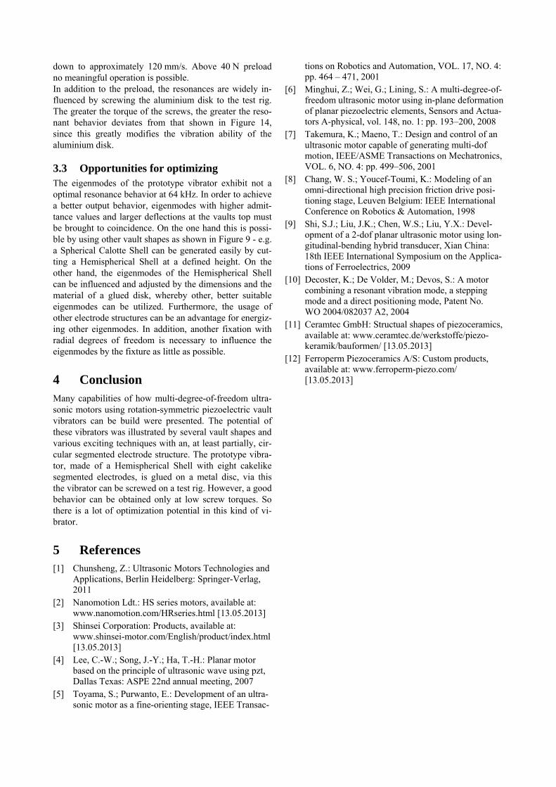
In case of the Hemispherical Shell, the graph of rotation is a quarter circle (Equation 1). This vault shape can be de-picted by only two independent parameters (here: radius r and shell thickness w). A Spherical Calotte Shell has an additional independent parameter (here: the height h), about what the eigenfrequencies can be influenced more extensive. The possibilities of a coincident pair of hori-zontal and vertical eigenmodes are even more extensive at Paraboloid and Bell Shells with four independent parame-ters. The Bell Shells exhibit additional eigenmodes due to the inflection point in the graph. Detailed studies of combinable eigenmodes and the influ-ence of geometrical parameters on the eigen-frequencies have not been performed yet for all these vault shapes. At this point, only the variety of possibilities is pointed up, to illustrate the potential of this type of vibrators. The production of individual piezoelectric ceramics with these special shapes is very laborious and entails high costs. But Hemispherical Shells can be found in the prod-uct portfolio of some manufacturers of ceramics ([11], [12]) and are available at affordable prices. Therefore, de-tailed studies were performed on this vault shape. CeramTec GmbH provides a Hemispherical Shell with r = 12 mm and w = 2 mm - made of the material “Sonox P5” - in their product portfolio. FEM-analyses of the free-vibrating Hemispherical Shell show which eigenmodes are suitable using the excitation structure described above. The first mode shapes (shown previously in Figure 5) lead to large amplitudes at the top of this Hemispherical Shell, however, they exhibit insufficient resonance behavior. That means, these eigenmodes are stimulable deficient via the electrodes on the inner and outer surface. Eigenmodes at higher frequencies (see Figure 10) show distinctly bet-ter resonance behavior, which can be seen on the high admittance values at 81880 Hz respectively 110487 Hz in Figure 11.
y
x
Horizontal mode at 110487 Hzy
x
Vertical mode at 81880 Hz
Figure 10 Eigenmodes with maximum admittance values in half section view Figure 11 shows the eigenfrequencies of vertical eigen-modes, which are not in coincidence with the eigenfre-quencies of horizontal eigenmodes. According to Figure 11, a simultaneous resonant excitation of two eigenmodes is not possible for the free-vibrating Hemispherical Shell. However, the vibrator has to be mounted on the stator to fasten it with the environment. This has a strong influence on the eigenmodes. For example, the Hemispherical Shell can be connected with the stator at its base area by an ad-hesive bond. The influence of such an adhesive bond is
elucidated in the following by means of a prototype vibra-tor.
0,0001
0,001
0,01
0,1
30000 40000 50000 60000 70000 80000 90000 100000 110000 120000 130000 140000 150000 160000
0,001
0,01
0,1
30000 40000 50000 60000 70000 80000 90000 100000 110000 120000 130000 140000 150000 160000
b) Horizontal modes (half symmetric out-of-phase excitation)
52542 Hz
91570 Hz
110487 Hz
138228 Hz
Frequency in Hz
Ad
mitta
nce
in
S
a) Vertical modes (rotation symmertic in-phase excitation)
145742 Hz
33358 Hz
81880 Hz
Ad
mitta
nce
in
S
Frequency in Hz
Figure 11 Admittance frequency response of the free-vibrating Hemispherical Shell
3 Prototype vibrator A Prototype vibrator is built up of the previously simu-lated Hemispherical Shell with r = 12 mm and w = 2 mm. The original ceramic has one all-over electrode on each inner and outer surface and the cakelike segmented elec-trode structure was created by ablation of the gaps via la-ser processing. On the top of the Hemispherical Shell a low-wear friction tappet is glued, see Figure 12. The Hemispherical Shell is glued on an aluminium disk, whereby it can be screwed onto a test rig.
Figure 12 Prototype vibrator
3.1 Test rig with changeable drive side variants
A test rig was built up that enables tests of vault vibrators on several drive side variants, see Figure 13. It is com-posed of a portal that can have several drive side modules inserted into it. The drive side modules are fixed by lat-eral clamps that are moveable to the vertical direction. Above the drive side modules is a preload module, which allows a fine adjustment of the vertical moveable drive side modules onto the vibrator. This is needed, in order to
investigate the influence of the preload on the drive side behavior (e.g. force and speed dependencies).
Figure 13 Test rig
3.2 Operating characteristics The Hemispherical Shell glued on the aluminium disk in-dicates another resonance behavior as the previously in-vestigated free-vibrating Hemispherical Shell, whose ei-genmodes no longer exist in the forms described above. Due to the adhesive connection many other eigenmodes occur, which result from a superposition of the eigen-modes of the aluminium disk and the Hemispherical Shell. The prototype vibrator works best by a frequency of about 64 kHz and can be driven both by multi-phase or single-phase excitation.
0,0001
0,001
0,01
0,1
30000 40000 50000 60000 70000 80000 90000 100000
0,0001
0,001
0,01
0,1
30000 40000 50000 60000 70000 80000 90000 100000
b) H (half symmetric out-of-phase excitation)orizontal modes
Frequency in Hz
Adm
itta
nce in S
a) V (rotation symmertic in-phase excitation)ertical modes
64000 Hz
Adm
itta
nce in S
Frequency in Hz
Figure 14 Measured admittance frequency response of the prototype vibrator In Figure 14 it can be seen that at 64 kHz the eigenfre-quencies of a vertical and a horizontal eigenmode are very close to each other, so that both get excited in resonance simultaneously. In this case an output speed of up to 400 mm/s - with 120 Vamp excitation voltage and 20 N preload force - is possible. By increasing the preload force up to 40 N, the maximum speed decreases continuously
down to approximately 120 mm/s. Above 40 N preload no meaningful operation is possible. In addition to the preload, the resonances are widely in-fluenced by screwing the aluminium disk to the test rig. The greater the torque of the screws, the greater the reso-nant behavior deviates from that shown in Figure 14, since this greatly modifies the vibration ability of the aluminium disk.
3.3 Opportunities for optimizing The eigenmodes of the prototype vibrator exhibit not a optimal resonance behavior at 64 kHz. In order to achieve a better output behavior, eigenmodes with higher admit-tance values and larger deflections at the vaults top must be brought to coincidence. On the one hand this is possi-ble by using other vault shapes as shown in Figure 9 - e.g. a Spherical Calotte Shell can be generated easily by cut-ting a Hemispherical Shell at a defined height. On the other hand, the eigenmodes of the Hemispherical Shell can be influenced and adjusted by the dimensions and the material of a glued disk, whereby other, better suitable eigenmodes can be utilized. Furthermore, the usage of other electrode structures can be an advantage for energiz-ing other eigenmodes. In addition, another fixation with radial degrees of freedom is necessary to influence the eigenmodes by the fixture as little as possible.
4 Conclusion Many capabilities of how multi-degree-of-freedom ultra-sonic motors using rotation-symmetric piezoelectric vault vibrators can be build were presented. The potential of these vibrators was illustrated by several vault shapes and various exciting techniques with an, at least partially, cir-cular segmented electrode structure. The prototype vibra-tor, made of a Hemispherical Shell with eight cakelike segmented electrodes, is glued on a metal disc, via this the vibrator can be screwed on a test rig. However, a good behavior can be obtained only at low screw torques. So there is a lot of optimization potential in this kind of vi-brator.
5 References [1] Chunsheng, Z.: Ultrasonic Motors Technologies and
Applications, Berlin Heidelberg: Springer-Verlag, 2011
[2] Nanomotion Ldt.: HS series motors, available at: www.nanomotion.com/HRseries.html [13.05.2013]
[3] Shinsei Corporation: Products, available at: www.shinsei-motor.com/English/product/index.html [13.05.2013]
[4] Lee, C.-W.; Song, J.-Y.; Ha, T.-H.: Planar motor based on the principle of ultrasonic wave using pzt, Dallas Texas: ASPE 22nd annual meeting, 2007
[5] Toyama, S.; Purwanto, E.: Development of an ultra-sonic motor as a fine-orienting stage, IEEE Transac-
tions on Robotics and Automation, VOL. 17, NO. 4: pp. 464 – 471, 2001
[6] Minghui, Z.; Wei, G.; Lining, S.: A multi-degree-of-freedom ultrasonic motor using in-plane deformation of planar piezoelectric elements, Sensors and Actua-tors A-physical, vol. 148, no. 1: pp. 193–200, 2008
[7] Takemura, K.; Maeno, T.: Design and control of an ultrasonic motor capable of generating multi-dof motion, IEEE/ASME Transactions on Mechatronics, VOL. 6, NO. 4: pp. 499–506, 2001
[8] Chang, W. S.; Youcef-Toumi, K.: Modeling of an omni-directional high precision friction drive posi-tioning stage, Leuven Belgium: IEEE International Conference on Robotics & Automation, 1998
[9] Shi, S.J.; Liu, J.K.; Chen, W.S.; Liu, Y.X.: Devel-opment of a 2-dof planar ultrasonic motor using lon-gitudinal-bending hybrid transducer, Xian China: 18th IEEE International Symposium on the Applica-tions of Ferroelectrics, 2009
[10] Decoster, K.; De Volder, M.; Devos, S.: A motor combining a resonant vibration mode, a stepping mode and a direct positioning mode, Patent No. WO 2004/082037 A2, 2004
[11] Ceramtec GmbH: Structual shapes of piezoceramics, available at: www.ceramtec.de/werkstoffe/piezo-keramik/bauformen/ [13.05.2013]
[12] Ferroperm Piezoceramics A/S: Custom products, available at: www.ferroperm-piezo.com/ [13.05.2013]
Magnetic Levitation System for Linear Direct Drives based on Lorentz Forces Dipl.-Ing. Benjamin Reutzsch; Prof. Dr.-Ing. Wolfgang Schinkoethe, Institute of Design and Pro-duction in Precision Engineering, University of Stuttgart, Germany Abstract Linear rolling and plain bearings are established and proven in Mechanical Engineering. However, for highest require-ments concerning stiffness, dynamics and durability, as well as in dust-free and vacuum rooms, usage of magnetically levitated linear bearings can be economically worthwhile. Existent magnetic levitation systems are designed in greater dimensions, especially for purposes of passenger transportation like the German Transrapid and for usage in machine tools [2] [1]. Furthermore, they are mostly based on electromagnets, what is firstly attended by damping effects due to eddy currents and hysteresis losses and secondly attended by need for complex closed-loop control algorithms. In this paper an innovative magnetic levitation system for linear direct drives is presented, that is exclusively based on Lorentz forces and which is designed in dimensions for application in precision engineering systems [3]. Permanent magnets are arranged similar to a Halbach array within the guideway and thereby establish a magnetic field for the levi-tation and guidance coils. The comparatively low weight of the moving part and its lack of eddy currents allow for highest dynamics. Moreover, easy and efficient closed-loop algorithms can be implemented because of the linear corre-lation of Lorentz force and current. Finally, the performance of the levitation system is shown using the example of an existing prototype.
1 Introduction Linear bearings are standard components in a wide range of industrial applications and are mostly designed as roll-ing or plain bearings. Nevertheless, for highest require-ments concerning stiffness, dynamics and durability, as well as in dust-free and vacuum environments, an imple-mentation of magnetically levitated linear bearings can make sense. These systems do not exhibit any mechanical friction and tribological wear and feature the possibility to adjust their stiffness according to their individual applica-tion. Most systems, which are part of scientific examina-tions are based on electromagnets and therefore show some disadvantages, such as damping effects. This paper presents an innovative magnetic levitation sys-tem for application in precision engineering, which is solely based on Lorentz forces and hence has inherent ad-vantages such as highest dynamics, compact design and low power requirements. After a short introduction in magnetic levitation technology, the basic design of all necessary components is shown, such as the configuration of permanent magnets in the guideway, the actuator coils in the moving part and positioning of displacement sen-sors. Afterwards, special requirements for use in precision engineering applications are discussed and feasible per-formance characteristics, such as motion speed, accelera-tion and dynamic stiffness of the proposed system are shown. Finally, comparisons with measurement results of a physical prototype are presented.
2 Magnetic Levitation Technology Magnetic levitation technology is widely connected with electromagnetic actuators, although there are more physi-cal principles that can technically be used for levitation purposes, such as electrodynamic, diamagnetic, supercon-ductive and ultrasonic levitation.
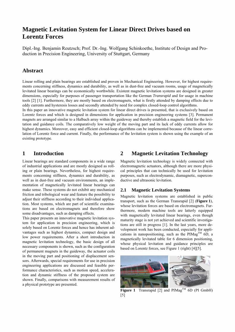
2.1 Magnetic Levitation Systems Magnetic levitation systems are established in public transport, such as the German Transrapid [2] (Figure 1), whose levitation forces are based on electromagnets. Fur-thermore, modern machine tools are latterly equipped with magnetically levitated linear bearings, even though maturity stage is not yet achieved and scientific investiga-tions are still in progress [1]. In the last years, more de-velopment work has been conducted, especially for appli-cations in nanopositioning, such as the PIMagTM 6D, a magnetically levitated table for 6 dimension positioning, whose physical levitation and guidance principles are based on Lorentz forces, see Figure 1 (right) [4][5].
Figure 1 Transrapid [2] and PIMagTM 6D (PI GmbH) [5]
2.2 Special Requirements for Levitated Systems in Precision Engineering
Most levitation systems exhibit comparatively great di-mensions and are therefore not applicable for precision engineering. Furthermore, special requirements must be considered for smaller dimensions, which determine de-sign and usage of physical principles:
Short travel distance, usually < 1 m, which pre-vents usage of electrodynamic levitation, where high velocities are needed.
Operation with safety-low voltage < 100 V, which leads to a slower increase of levitation forces.
Light weight of the moving part < 10 kg, so that an active force is needed, facing downwards in direction of gravity.
Small load forces in process < 100 N. Compact design. Passive compensation of weight for low power
requirements in static state of levitation.
3 Basic Configuration The innovative design of a levitation system for usage in precision engineering applications and exclusively based on Lorentz forces is now presented.
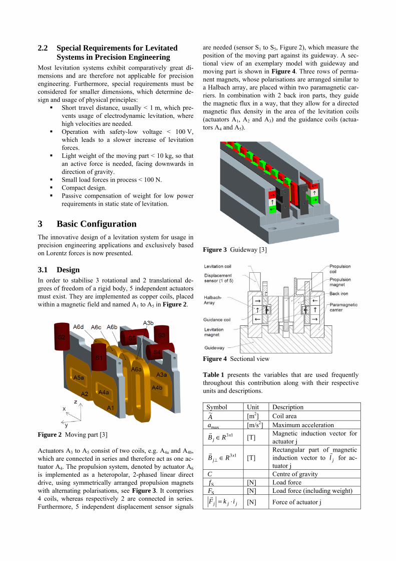
3.1 Design In order to stabilise 3 rotational and 2 translational de-grees of freedom of a rigid body, 5 independent actuators must exist. They are implemented as copper coils, placed within a magnetic field and named A1 to A5 in Figure 2.
Figure 2 Moving part [3] Actuators A3 to A5 consist of two coils, e.g. A4a and A4b, which are connected in series and therefore act as one ac-tuator A4. The propulsion system, denoted by actuator A6 is implemented as a heteropolar, 2-phased linear direct drive, using symmetrically arranged propulsion magnets with alternating polarisations, see Figure 3. It comprises 4 coils, whereas respectively 2 are connected in series. Furthermore, 5 independent displacement sensor signals
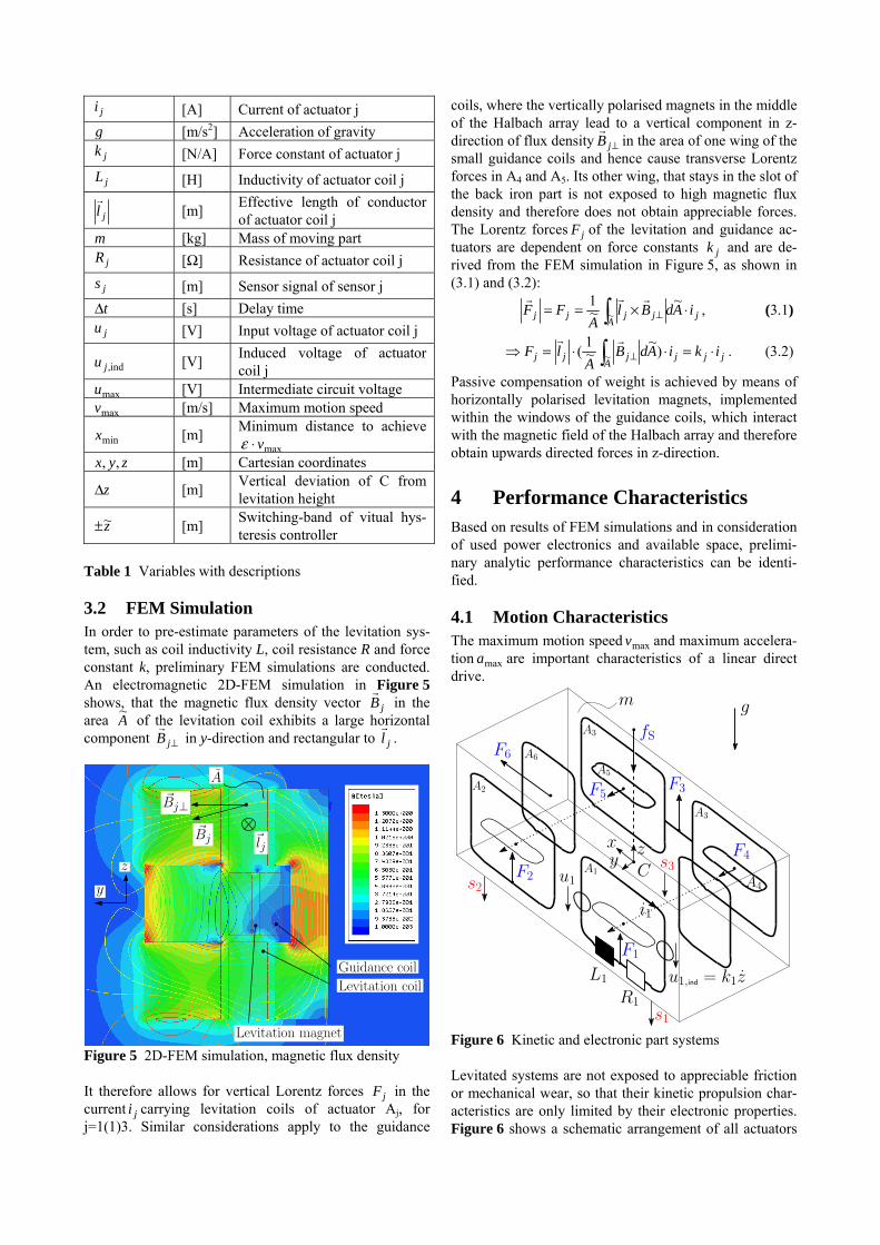
are needed (sensor S1 to S5, Figure 2), which measure the position of the moving part against its guideway. A sec-tional view of an exemplary model with guideway and moving part is shown in Figure 4. Three rows of perma-nent magnets, whose polarisations are arranged similar to a Halbach array, are placed within two paramagnetic car-riers. In combination with 2 back iron parts, they guide the magnetic flux in a way, that they allow for a directed magnetic flux density in the area of the levitation coils (actuators A1, A2 and A3) and the guidance coils (actua-tors A4 and A5).
Figure 3 Guideway [3]
Figure 4 Sectional view Table 1 presents the variables that are used frequently throughout this contribution along with their respective units and descriptions.
Symbol Unit Description
A~ [m2] Coil area
maxa [m/s2] Maximum acceleration
13xj RB
[T] Magnetic induction vector for actuator j
13xj RB
[T] Rectangular part of magnetic induction vector to jl
for ac-
tuator j C Centre of gravity
Sf [N] Load force
SF [N] Load force (including weight)
jjj ikF
[N] Force of actuator j
ji [A] Current of actuator j
g [m/s2] Acceleration of gravity
jk [N/A] Force constant of actuator j
jL [H] Inductivity of actuator coil j
jl
[m] Effective length of conductor of actuator coil j
m [kg] Mass of moving part
jR [] Resistance of actuator coil j
js [m] Sensor signal of sensor j
t [s] Delay time
ju [V] Input voltage of actuator coil j
ind,ju [V] Induced voltage of actuator coil j
maxu [V] Intermediate circuit voltage
maxv [m/s] Maximum motion speed
minx [m] Minimum distance to achieve
maxv zyx ,, [m] Cartesian coordinates
z [m] Vertical deviation of C from levitation height
z~ [m] Switching-band of vitual hys-teresis controller
Table 1 Variables with descriptions
3.2 FEM Simulation In order to pre-estimate parameters of the levitation sys-tem, such as coil inductivity L, coil resistance R and force constant k, preliminary FEM simulations are conducted. An electromagnetic 2D-FEM simulation in Figure 5 shows, that the magnetic flux density vector jB
in the
area A~
of the levitation coil exhibits a large horizontal component jB
in y-direction and rectangular to jl
.
A
�Bj
�Bj⊥
Levitation magnet
Guidance coil
y
z
�lj
Levitation coil
Figure 5 2D-FEM simulation, magnetic flux density It therefore allows for vertical Lorentz forces jF in the current ji carrying levitation coils of actuator Aj, for j=1(1)3. Similar considerations apply to the guidance
coils, where the vertically polarised magnets in the middle of the Halbach array lead to a vertical component in z-direction of flux density jB
in the area of one wing of the
small guidance coils and hence cause transverse Lorentz forces in A4 and A5. Its other wing, that stays in the slot of the back iron part is not exposed to high magnetic flux density and therefore does not obtain appreciable forces. The Lorentz forces jF of the levitation and guidance ac-tuators are dependent on force constants jk and are de-rived from the FEM simulation in Figure 5, as shown in (3.1) and (3.2):
jA
jjjj iAdBlA
FF ~
~1
~
, (3.1)
jjjA
jjj ikiAdBA
lF )~
~1
( ~
. (3.2)
Passive compensation of weight is achieved by means of horizontally polarised levitation magnets, implemented within the windows of the guidance coils, which interact with the magnetic field of the Halbach array and therefore obtain upwards directed forces in z-direction.
4 Performance Characteristics Based on results of FEM simulations and in consideration of used power electronics and available space, prelimi-nary analytic performance characteristics can be identi-fied.
4.1 Motion Characteristics The maximum motion speed maxv and maximum accelera-tion maxa are important characteristics of a linear direct drive.
L1
R1
u1
u1,ind = k1z
i1
yx z
C
F1
m
fS
A1
A2
A3
F6 A6
F2
F3
F4
F5
A4
A5
A3
s1
s2
s3
g
Figure 6 Kinetic and electronic part systems Levitated systems are not exposed to appreciable friction or mechanical wear, so that their kinetic propulsion char-acteristics are only limited by their electronic properties. Figure 6 shows a schematic arrangement of all actuators
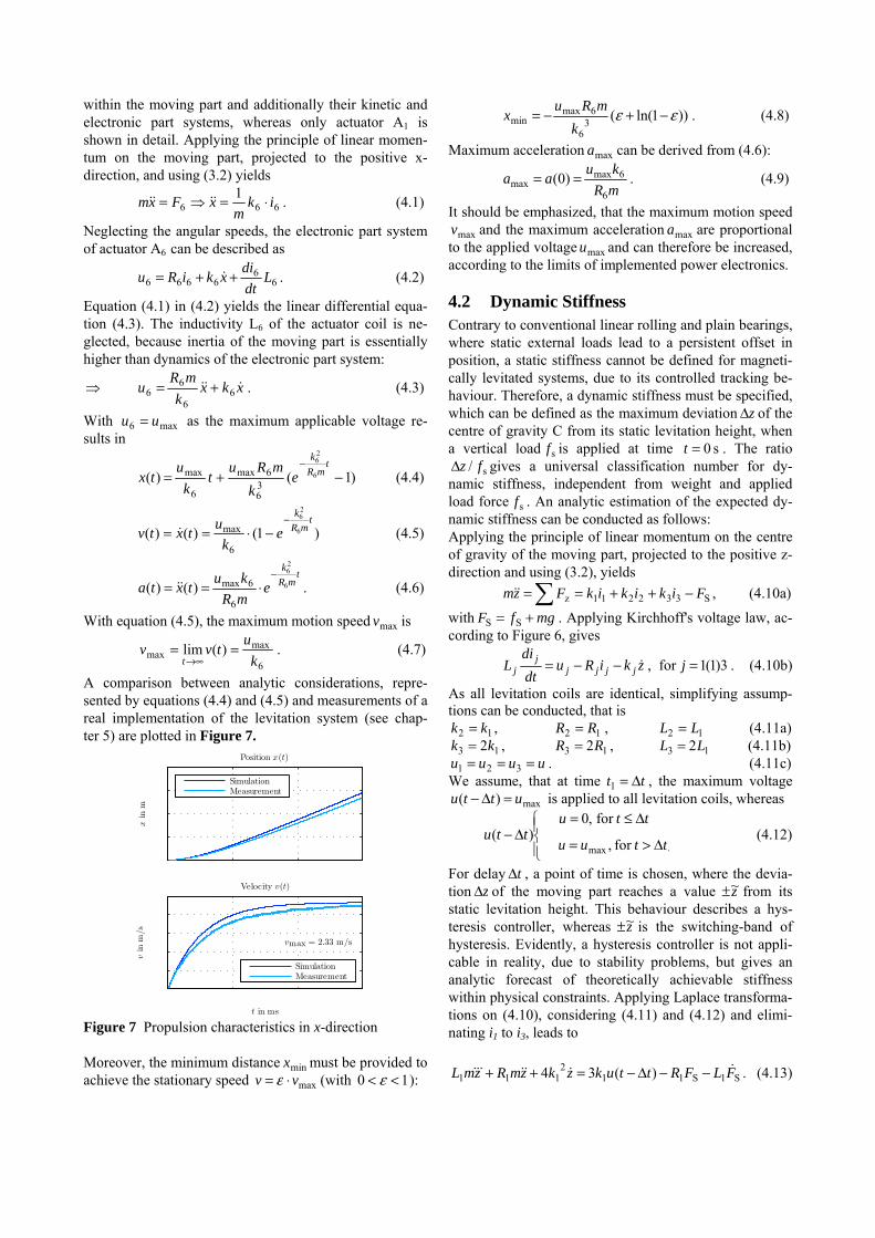
within the moving part and additionally their kinetic and electronic part systems, whereas only actuator A1 is shown in detail. Applying the principle of linear momen-tum on the moving part, projected to the positive x-direction, and using (3.2) yields
6661
ikm
xFxm . (4.1)
Neglecting the angular speeds, the electronic part system of actuator A6 can be described as
66
6666 Ldt
dixkiRu . (4.2)
Equation (4.1) in (4.2) yields the linear differential equa-tion (4.3). The inductivity L6 of the actuator coil is ne-glected, because inertia of the moving part is essentially higher than dynamics of the electronic part system:
xkxk
mRu 6
6
66 . (4.3)
With max6 uu as the maximum applicable voltage re-sults in
)1()( 6
26
36
6max
6
max t
mR
k
ek
mRut
k
utx (4.4)
)1()()( 6
26
6
maxt
mR
k
ek
utxtv
(4.5)
tmR
k
emR
kutxta 6
26
6
6max)()(
. (4.6)
With equation (4.5), the maximum motion speed maxv is
6
maxmax )(lim
k
utvv
t
. (4.7)
A comparison between analytic considerations, repre-sented by equations (4.4) and (4.5) and measurements of a real implementation of the levitation system (see chap-ter 5) are plotted in Figure 7.
� �� ��� ����
���
���
���
���
xin
m
Position x(t)
SimulationMeasurement
� �� ��� ����
���
�
���
�
���
t in ms
vin
m/s
Velocity v(t)
vmax = 2.33 m/s
umax = 35 V SimulationMeasurement
Figure 7 Propulsion characteristics in x-direction Moreover, the minimum distance minx must be provided to achieve the stationary speed maxvv (with 10 ):
))1ln((3
6
6maxmin
k
mRux . (4.8)
Maximum acceleration maxa can be derived from (4.6):
mR
kuaa
6
6maxmax )0( . (4.9)
It should be emphasized, that the maximum motion speed
maxv and the maximum acceleration maxa are proportional to the applied voltage maxu and can therefore be increased, according to the limits of implemented power electronics.
4.2 Dynamic Stiffness Contrary to conventional linear rolling and plain bearings, where static external loads lead to a persistent offset in position, a static stiffness cannot be defined for magneti-cally levitated systems, due to its controlled tracking be-haviour. Therefore, a dynamic stiffness must be specified, which can be defined as the maximum deviation z of the centre of gravity C from its static levitation height, when a vertical load sf is applied at time s 0t . The ratio
s/ fz gives a universal classification number for dy-namic stiffness, independent from weight and applied load force sf . An analytic estimation of the expected dy-namic stiffness can be conducted as follows: Applying the principle of linear momentum on the centre of gravity of the moving part, projected to the positive z-direction and using (3.2), yields
S332211z FikikikFzm , (4.10a)
with mgfF SS . Applying Kirchhoff's voltage law, ac-cording to Figure 6, gives
zkiRudt
diL jjjj
jj , for 3)1(1j . (4.10b)
As all levitation coils are identical, simplifying assump-tions can be conducted, that is
12 kk , 12 RR , 12 LL (4.11a)
13 2kk , 13 2RR , 13 2LL (4.11b) uuuu 321 . (4.11c)
We assume, that at time tt 1 , the maximum voltage
max)( uttu is applied to all levitation coils, whereas
ttuu
ttuttu
for ,
for ,0)(
max (4.12)
For delay t , a point of time is chosen, where the devia-tion z of the moving part reaches a value z~ from its static levitation height. This behaviour describes a hys-teresis controller, whereas z~ is the switching-band of hysteresis. Evidently, a hysteresis controller is not appli-cable in reality, due to stability problems, but gives an analytic forecast of theoretically achievable stiffness within physical constraints. Applying Laplace transforma-tions on (4.10), considering (4.11) and (4.12) and elimi-nating i1 to i3, leads to
S1S112
111 )(34 FLFRttukzkzmRzmL . (4.13)
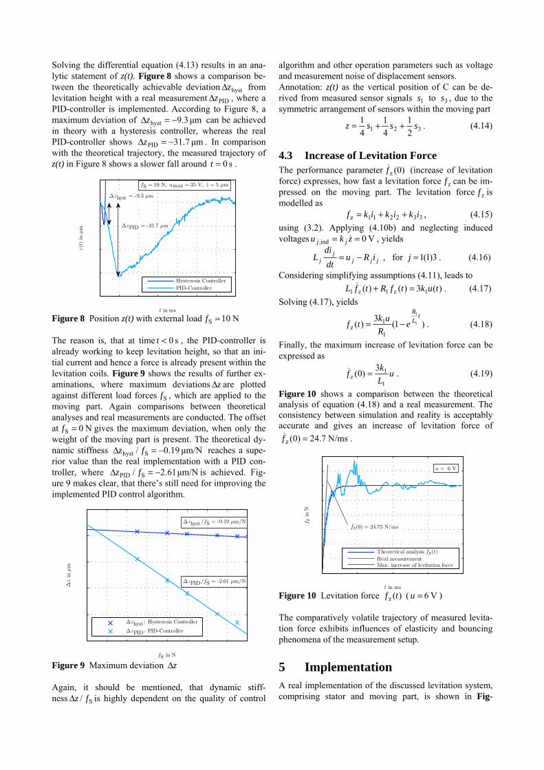
Solving the differential equation (4.13) results in an ana-lytic statement of z(t). Figure 8 shows a comparison be-tween the theoretically achievable deviation hystz from levitation height with a real measurement PIDz , where a PID-controller is implemented. According to Figure 8, a maximum deviation of μm 3.9hyst z can be achieved in theory with a hysteresis controller, whereas the real PID-controller shows μm 7.31PID z . In comparison with the theoretical trajectory, the measured trajectory of z(t) in Figure 8 shows a slower fall around s 0t .
� � �� �� �� �� �� �����
���
���
���
�
��
t in ms
z(t
)in
μm
fS = 10 N, umax = 35 V, z = 5 μm
Δzhyst = -9.3 μm
ΔzPID = -31.7 μm
Hysteresis ControllerPID-Controller
Figure 8 Position z(t) with external load N 10S f The reason is, that at time s 0t , the PID-controller is already working to keep levitation height, so that an ini-tial current and hence a force is already present within the levitation coils. Figure 9 shows the results of further ex-aminations, where maximum deviations z are plotted against different load forces Sf , which are applied to the moving part. Again comparisons between theoretical analyses and real measurements are conducted. The offset at N 0S f gives the maximum deviation, when only the weight of the moving part is present. The theoretical dy-namic stiffness μm/N 19.0/ Shyst fz reaches a supe-rior value than the real implementation with a PID con-troller, where μm/N 61.2/ SPID fz is achieved. Fig-ure 9 makes clear, that there’s still need for improving the implemented PID control algorithm.
� � � � � �� �� �� �����
���
���
���
���
�
fS in N
Δz
inμm
Δzhyst /fS = -0.19 μm/N
ΔzPID/fS = -2.61 μm/N
Δzhyst : Hysteresis Controller
ΔzPID: PID-Controller
Figure 9 Maximum deviation z Again, it should be mentioned, that dynamic stiff-ness S/ fz is highly dependent on the quality of control
algorithm and other operation parameters such as voltage and measurement noise of displacement sensors. Annotation: z(t) as the vertical position of C can be de-rived from measured sensor signals 1s to 3s , due to the symmetric arrangement of sensors within the moving part
321 2
1
4
1
4
1sssz . (4.14)
4.3 Increase of Levitation Force The performance parameter )0(zf
(increase of levitation force) expresses, how fast a levitation force zf can be im-pressed on the moving part. The levitation force zf is modelled as
332211z ikikikf , (4.15)
using (3.2). Applying (4.10b) and neglecting induced voltages V 0ind, zku jj , yields
jjjj
j iRudt
diL , for 3)1(1j . (4.16)
Considering simplifying assumptions (4.11), leads to
)(3)()( 1z1z1 tuktfRtfL . (4.17)
Solving (4.17), yields
)1(3
)( 1
1
1
1z
tL
R
eR
uktf . (4.18)
Finally, the maximum increase of levitation force can be expressed as
uL
kf
1
1z
3)0( . (4.19)
Figure 10 shows a comparison between the theoretical analysis of equation (4.18) and a real measurement. The consistency between simulation and reality is acceptably accurate and gives an increase of levitation force of
N/ms 7.24)0(z f .
� �� �� �� ���
��
��
��
��
��
��
��
��
t in ms
fz
inN
u = 6 V
fz(0) = 24.75 N/ms
Theoretical analysis fz(t)Real measurementMax. increase of levitation force
Figure 10 Levitation force )(z tf ( V 6 u ) The comparatively volatile trajectory of measured levita-tion force exhibits influences of elasticity and bouncing phenomena of the measurement setup.
5 Implementation A real implementation of the discussed levitation system, comprising stator and moving part, is shown in Fig-
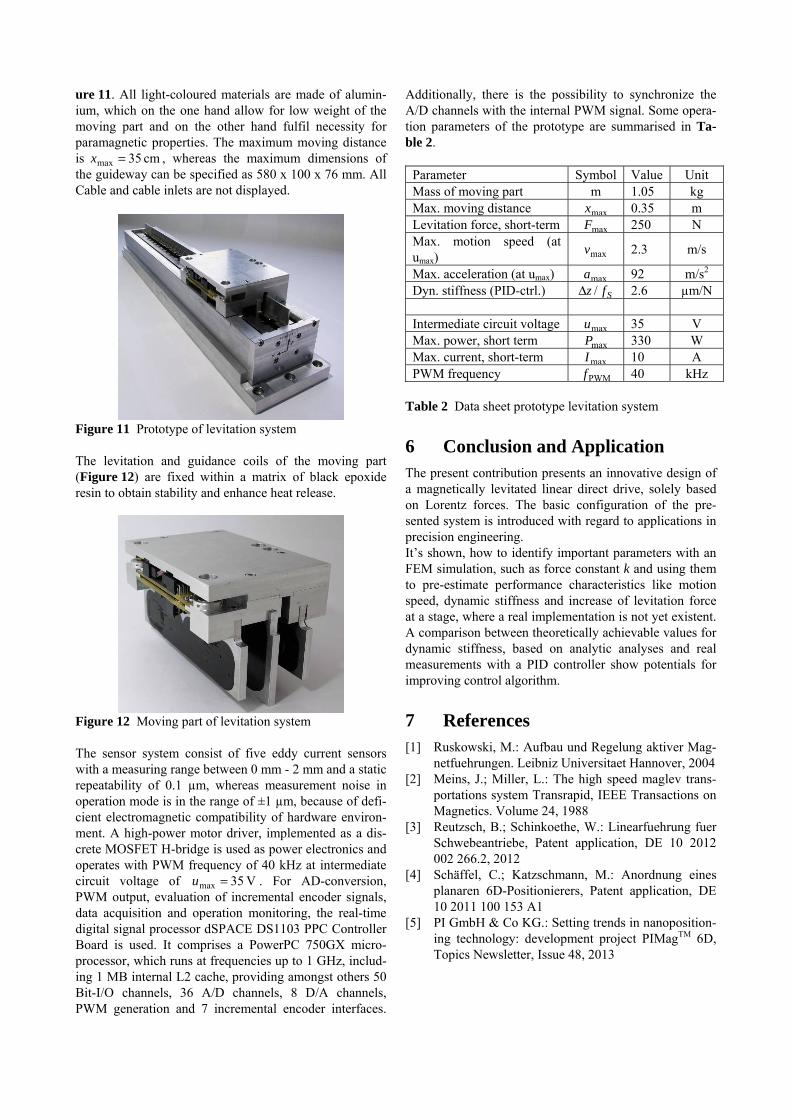
ure 11. All light-coloured materials are made of alumin-ium, which on the one hand allow for low weight of the moving part and on the other hand fulfil necessity for paramagnetic properties. The maximum moving distance is cm 35max x , whereas the maximum dimensions of the guideway can be specified as 580 x 100 x 76 mm. All Cable and cable inlets are not displayed.
Figure 11 Prototype of levitation system The levitation and guidance coils of the moving part (Figure 12) are fixed within a matrix of black epoxide resin to obtain stability and enhance heat release.
Figure 12 Moving part of levitation system The sensor system consist of five eddy current sensors with a measuring range between 0 mm - 2 mm and a static repeatability of 0.1 µm, whereas measurement noise in operation mode is in the range of ±1 µm, because of defi-cient electromagnetic compatibility of hardware environ-ment. A high-power motor driver, implemented as a dis-crete MOSFET H-bridge is used as power electronics and operates with PWM frequency of 40 kHz at intermediate circuit voltage of V 35max u . For AD-conversion, PWM output, evaluation of incremental encoder signals, data acquisition and operation monitoring, the real-time digital signal processor dSPACE DS1103 PPC Controller Board is used. It comprises a PowerPC 750GX micro-processor, which runs at frequencies up to 1 GHz, includ-ing 1 MB internal L2 cache, providing amongst others 50 Bit-I/O channels, 36 A/D channels, 8 D/A channels, PWM generation and 7 incremental encoder interfaces.
Additionally, there is the possibility to synchronize the A/D channels with the internal PWM signal. Some opera-tion parameters of the prototype are summarised in Ta-ble 2.
Parameter Symbol Value Unit Mass of moving part m 1.05 kg Max. moving distance maxx 0.35 m Levitation force, short-term maxF 250 N Max. motion speed (at umax) maxv 2.3 m/s
Max. acceleration (at umax) maxa 92 m/s2 Dyn. stiffness (PID-ctrl.) Sfz / 2.6 µm/N Intermediate circuit voltage maxu 35 V Max. power, short term maxP 330 W Max. current, short-term maxI 10 A PWM frequency PWMf 40 kHz
Table 2 Data sheet prototype levitation system
6 Conclusion and Application The present contribution presents an innovative design of a magnetically levitated linear direct drive, solely based on Lorentz forces. The basic configuration of the pre-sented system is introduced with regard to applications in precision engineering. It’s shown, how to identify important parameters with an FEM simulation, such as force constant k and using them to pre-estimate performance characteristics like motion speed, dynamic stiffness and increase of levitation force at a stage, where a real implementation is not yet existent. A comparison between theoretically achievable values for dynamic stiffness, based on analytic analyses and real measurements with a PID controller show potentials for improving control algorithm.
7 References [1] Ruskowski, M.: Aufbau und Regelung aktiver Mag-
netfuehrungen. Leibniz Universitaet Hannover, 2004 [2] Meins, J.; Miller, L.: The high speed maglev trans-
portations system Transrapid, IEEE Transactions on Magnetics. Volume 24, 1988
[3] Reutzsch, B.; Schinkoethe, W.: Linearfuehrung fuer Schwebeantriebe, Patent application, DE 10 2012 002 266.2, 2012
[4] Schäffel, C.; Katzschmann, M.: Anordnung eines planaren 6D-Positionierers, Patent application, DE 10 2011 100 153 A1
[5] PI GmbH & Co KG.: Setting trends in nanoposition-ing technology: development project PIMagTM 6D, Topics Newsletter, Issue 48, 2013


![[DIN 58405-3-1972-05] -- Stirnradgetriebe der Feinwerktechnik; Angaben in Zeichnungen, Berechnungsbeispiele.pdf](https://img.pdfslide.org/doc/110x75/56d6bfa41a28ab3016970e27/din-58405-3-1972-05-stirnradgetriebe-der-feinwerktechnik-angaben-in-zeichnungen.jpg)