Embed Size (px)
Citation preview
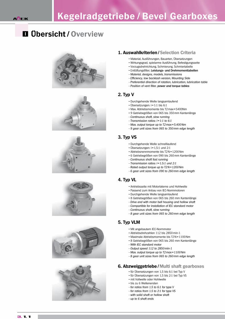
Übersicht / Overview
1. Auswahlkriterien / Selection Criteria
Material, Ausführungen, Bauarten, Übersetzungen
Wirkungsgrad, spielarme Ausführung, Befestigungsseite
Vorzugsdrehrichtung, Schmierung, Schmiertabelle
Entlüftungsfilter, Leistungs- und Drehmomenttabellen
- Material, designs, models, transmissions
- Efficiency, low backlash version, Mounting Side
- Preferential direction of rotation, lubrication, lubrication table
- Position of vent filter, power and torque tables
2. Typ V
Durchgehende Welle langsamlaufend
Übersetzungen: i = 1:1 bis 6:1
Max. Abtriebsmomente bis T2 max = 5400Nm
9 Getriebegrößen von 065 bis 350 mm Kantenlänge
- Continuous shaft, slow running
- Transmission ratios: i = 1:1 to 6:1
- Max. output torque up to T2 max = 5.400 Nm
- 9 gear unit sizes from 065 to 350 mm edge length
3. Typ VS
Durchgehende Welle schnelllaufend
Übersetzungen: i = 1,5:1 und 2:1
Abtriebsnennmomente bis T2 N = 1200 Nm
6 Getriebegrößen von 090 bis 260 mm Kantenlänge
- Continuous shaft fast running
- Transmission ratios: i = 1.5:1 und 2:1
- Rated output torque up to T2 N = 1200 Nm
- 6 gear unit sizes from 090 to 260 mm edge length
4. Typ VL
Antriebsseite mit Motorlaterne und Hohlwelle
Passend zum Anbau von IEC-Normmotoren
Durchgehende Welle langsamlaufend
8 Getriebegrößen von 065 bis 260 mm Kantenlänge
- Drive end with motor bell housing and hollow shaft
- Compartible for installation of IEC standard motor
- Continuous shaft, slow running
- 8 gear unit sizes from 065 to 260 mm edge length
5. Typ VLM
Mit angebautem IEC-Normmotor
Abtriebsdrehzahlen 112 bis 2850 min-1
Maximale Abtriebsmomente bis T2 N = 1100 Nm
8 Getriebegrößen von 065 bis 260 mm Kantenlänge
- With IEC standard motor
- Output speed 112 to 2850 min-1
- Max. output torque up to T2 max = 1100 Nm
- 8 gear unit sizes from 065 to 260 mm edge length
6. Abzweiggetriebe / Multi shaft gearboxes für Übersetzungen von 1,5 bis 6:1 bei Typ V
für Übersetzungen von 1,5 bis 2:1 bei Typ VS
mit Vollwelle oder Hohlwelle
bis zu 6 Wellenenden
- for ratios from 1.5 to 6:1 for type V
- for ratios from 1.5 to 2:1 for type VS
- with solid shaft or hollow shaft
- up to 6 shaft ends
3. 1. 1
Kegelradgetriebe / Bevel Gearboxes
Kegelra
dgetrie
be T
yp V
B
eve
l Ge
arb
oxe
s T
yp
e V
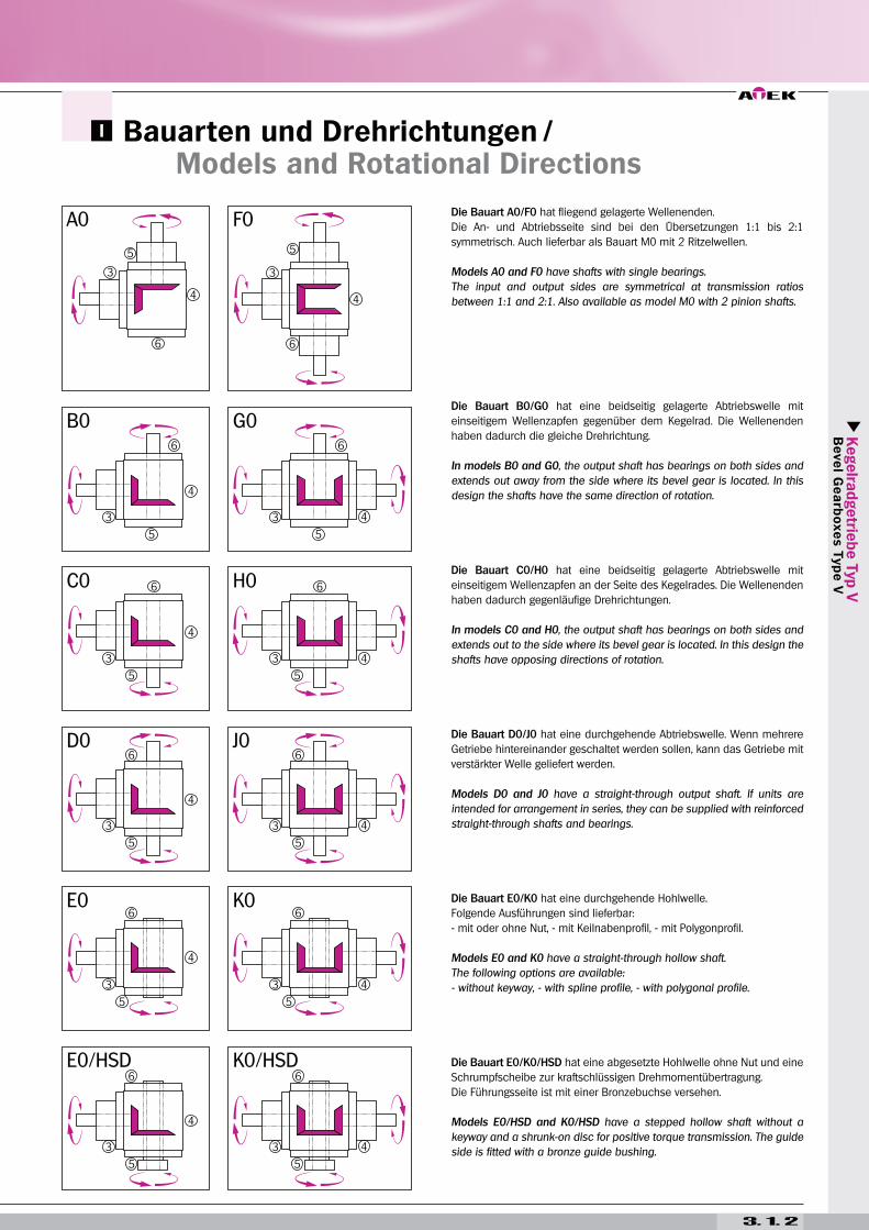
Die Bauart A0/F0 hat fliegend gelagerte Wellenenden.
Die An- und Abtriebsseite sind bei den Übersetzungen 1:1 bis 2:1
symmetrisch. Auch lieferbar als Bauart M0 mit 2 Ritzelwellen.
Models A0 and F0 have shafts with single bearings.
The input and output sides are symmetrical at transmission ratios
between 1:1 and 2:1. Also available as model M0 with 2 pinion shafts.
Die Bauart B0/G0 hat eine beidseitig gelagerte Abtriebswelle mit
einseitigem Wellenzapfen gegenüber dem Kegelrad. Die Wellenenden
haben dadurch die gleiche Drehrichtung.
In models B0 and G0, the output shaft has bearings on both sides and
extends out away from the side where its bevel gear is located. In this
design the shafts have the same direction of rotation.
Die Bauart C0/H0 hat eine beidseitig gelagerte Abtriebswelle mit
einseitigem Wellenzapfen an der Seite des Kegelrades. Die Wellenenden
haben dadurch gegenläufige Drehrichtungen.
In models C0 and H0, the output shaft has bearings on both sides and
extends out to the side where its bevel gear is located. In this design the
shafts have opposing directions of rotation.
Die Bauart D0/J0 hat eine durchgehende Abtriebswelle. Wenn mehrere
Getriebe hintereinander geschaltet werden sollen, kann das Getriebe mit
verstärkter Welle geliefert werden.
Models D0 and J0 have a straight-through output shaft. If units are
intended for arrangement in series, they can be supplied with reinforced
straight-through shafts and bearings.
Die Bauart E0/K0 hat eine durchgehende Hohlwelle.
Folgende Ausführungen sind lieferbar:
- mit oder ohne Nut, - mit Keilnabenprofil, - mit Polygonprofil.
Models E0 and K0 have a straight-through hollow shaft.
The following options are available:
- without keyway, - with spline profile, - with polygonal profile.
Die Bauart E0/K0/HSD hat eine abgesetzte Hohlwelle ohne Nut und eine
Schrumpfscheibe zur kraftschlüssigen Drehmomentübertragung.
Die Führungsseite ist mit einer Bronzebuchse versehen.
Models E0/HSD and K0/HSD have a stepped hollow shaft without a
keyway and a shrunk-on disc for positive torque transmission. The guide
side is fitted with a bronze guide bushing.
Bauarten und Drehrichtungen / Models and Rotational Directions
3. 1. 2
Auswahlkriterien / Selection Criteria
ATEK bevel gearboxes are encased in robust cast metal housings and
have hardened bevel gears pairs with spiral toothing and amply dimen-
sioned rolling bearings. Spiral bevel gears have the significant benefit of
very favourable meshing characteristics (high contact ratio). They are
therefore especially well suited for operation under high load factors
and when the highest smoothness of running and a high degree of
trans-mission precision are required.
The curved teeth are more resistant to distortion than are straight or
helical teeth. A further benefit is their relative insensitivity to elastic dis-
tortion of wheels, shafts and bearings. The gearboxes are thus able to
transmit extreme shock loads. A total of twelve different standard ver-
sions are available, with a further 22 variations as multi-shaft gear-boxes.
All gearboxes may be installed in any mounting position and may have
mounting holes on all sides.
Transmission Ratios
Transmission ratios of 1 - 1.5 - 2 - 3 - 4 - 5 and 6:1 are available as stan-
dard. All transmission ratios are mathematically precise. The gears can
be used for gearing down and gearing up. Special transmission ratios
are available. Please contact us for details.
Efficiency
ATEK gearboxes are 94 - 98 % efficient, depending on rpm, mounting
position, sealing and type of lubrication.
The efficiency level refers to the nominal power output from the trans-
mission. In certain mounting positions, the bevel gears are completely
immersed in the lubricant. In this case, churning loss in larger gearboxes
and at high circumferential velocities of the wheels can be considerable
and ATEK should be consulted.
In general, it should be noted that starting efficiency is always lower than
operating efficiency. The resulting increased breakaway torque should be
taken into consideration when determining the driving power required.
Low-backlash version
For standard bevel gear units have – depending on gear size and ratio
– a backlash of 10 to 30 angular minutes. Neverthless all ATEK bevel
gearboxes can be supplied in a low-backlash version.
When the drive shaft is locked, tooth backlash on the slowly-running
shaft is measured on a 100 mm lever arm with a measuring force of 3%
of the rated torque and then is given as a torsion angle.
The following values can be set with standard gear sets.
Design S1: i = 1:1 bis 2:1 < 6 angular minutes
Design S2: i = 3:1 bis 6:1 < 10 angular minutes
Tighter values can be obtained from specially selected, HPGS-geared or
ground gear sets – please ask (Design S0).
Mounting Side
To indicate clearly the positions of different gearbox features, the sides
of the gearbox are numbered 1 to 6. These numbers can be found in the
individual data sheets.
All six sides of the gearbox are machined and can be used as mounting
surfaces. The flanges and neck flanges are fitted with threaded holes as
standard equipment. The following ordering options are available:
Code Mounting holes
0 only in the flange surfaces
9 on all gearbox sides without flanges
9G on all gearbox sides with flange / neck flange
ATEK-Kegelradgetriebe haben kräftige Graugussgehäuse, gehärtete und
paarweise geläppte Kegelräder mit Spiralverzahnung und reichlich
dimensionierte Wälzlager. Spiralkegelräder bieten den entscheidenden
Vorteil sehr günstiger Eingriffsverhältnisse (hoher Überdeckungsgrad). Sie
sind dadurch prädestiniert für den Einsatz bei hohen Belastungen,
gepaart mit optimaler Laufruhe und großer Übertragungsgenauigkeit.
Die kreisbogenförmigen Zähne sind gegen Biegung widerstandsfähiger als
gerade oder schräge Zähne. Ein weiterer Vorteil ist die relative Unempfind-
lichkeit gegen elastische Verformung von Rädern, Wellen und Lagern. Die
Getriebe können daher auch extreme Stoßbelastungen übertragen. Zwölf
Bauarten stehen serienmäßig zur Verfügung. 22 weitere Variationen sind als
Abzweiggetriebe möglich. Die Getriebe können in allen Einbaulagen einge-
setzt und mit vielfältigen Befestigungsbohrungen versehen werden. Deckel
und Flansche werden generell mit Befestigungsbohrungen versehen.
Übersetzungen
Als Standard-Übersetzungen sind lieferbar: 1 - 1,5 - 2 - 3 - 4 - 5 und 6:1. Alle
Übersetzungen sind mathematisch genau. Die Getriebe können für Über-
setzungen ins Langsame und ins Schnelle eingesetzt werden. Sonder-
übersetzungen sind lieferbar. Bitte fragen Sie bei uns an.
Wirkungsgrad
Der Wirkungsgrad der ATEK-Kegelradgetriebe beträgt 94 - 98 %, abhängig
von Drehzahl, Einbaulage, Abdichtung und Schmierstoffart. Die Wirkungs-
grade beziehen sich auf die Nennleistungen der Getriebe.
Bei bestimmten Einbaulagen tauchen die Kegelräder voll in das Schmier-
mittel ein. Hier sind bei größeren Getrieben und hohen Umfangsge-
schwindigkeiten der Räder die Planschverluste nicht zu vernachlässigen
und bedingen Rücksprache mit ATEK.
Zu beachten ist, dass der Anlaufwirkungsgrad stets kleiner als der Be-
triebswirkungsgrad ist. Das entstehende, erhöhte Losbrechmoment ist
bei der Auslegung der Antriebsleistung zu berücksichtigen.
Spielarme Ausführung
Standardmäßig haben die Kegelradgetriebe – abhängig von Getriebegröße
und Übersetzung – ein Verdrehflankenspiel von 10 bis 30 Winkelminuten.
Alle ATEK-Kegelradgetriebe können jedoch in spielarmer Ausführung
geliefert werden.
Das Verdrehflankenspiel an der langsam laufenden Welle wird bei blockier-
ter Antriebswelle auf einem Hebelarm von 100 mm mit einer Messkraft von
3 % des Nennmoments gemessen und als Verdrehwinkel angegeben.
Folgende Werte sind mit Normalradsätzen einstellbar:
Ausführung S1: i = 1:1 bis 2:1 6 Winkelminuten
Ausführung S2: i = 3:1 bis 6:1 10 Winkelminuten
Engere Werte erfordern ausgesuchte, HPGS-verzahnte oder geschliffene
Radsätze – bitte anfragen (Ausführung S0).
Befestigungsseite
Um die Lage verschiedener Getriebemerkmale eindeutig zu bestimmen,
sind die Seiten der Getriebe mit den Ziffern 1 bis 6 nummeriert. Diese
Nummern finden sich in den einzelnen Datenblättern wieder.
Alle 6 Seiten der Getriebe sind bearbeitet und können als Befestigungs-
flächen benutzt werden. Das V350 hat serienmäßig an allen Getriebesei-
ten Befestigungsbohrungen im Gehäuse. Alle Flanschflächen haben
serienmäßig immer Befestigungsbohrungen! Folgende Bestelloptionen
stehen Ihnen zur Verfügung:
Code Befestigungsbohrungen
0 nur in den Flanschflächen
9 an allen Gehäuseseiten ohne Flansch (Seiten 1, 2 und 4)
9G an allen Gehäuseseiten mit Flansch (Seiten 3, 5 und 6)
3. 1. 3
Auswahlkriterien / Selection Criteria
Kegelra
dgetrie
be T
yp V
B
eve
l Ge
arb
oxe
s T
yp
e V
Preferred rotational direction
ATEK bevel gearboxes can normally be run in either
rotational direction. The spiral direction of the gear set
and the rotational direction used are key factors deter-
mining the forces evolved within the unit. In most
instances permissible torque transmission can be
maximized by using the gear pairing such that the driv-
ing gear rotates in the same direction as the spiralling. This arrangement
creates a more favourable contact point which reduces gear distortion.
This also reduces noise from the gear pairing by 1-2 dBA due to the fact
that the axial forces caused by the spiral meshing push the gears apart.
In ATEK bevel gear transmissions the pinion gear always has a left-handed
spiral; accordingly, the large gear has a right-handed spiral.
Lubrication
ATEK bevel gearboxes are supplied oil-filled and are maintenance-free
under normal operating conditions. With extreme requirements or
increased demands on durability we recommend to change the oil after
approx. 15,000 hours of operation.
ATEK is anxious to select the best lubricants for each case of application
and in so doing optimizing the lifetime of the transmission. The periphe-
ral speed of the bevel gears, the power that is to be transferred, and the
operating conditions are crucial for the choice of the lubricant.
An approximate guideline value for the type of lubrication used can be
found in the two selection diagrams and in the lubricant table.
The way to the correct type of lubrication is to be found using the two
selection diagrams and the lubricant table. The selection diagrams con-
sider the nominal moment, as taken from catalogue, and the operating
mode of the transmission with 100 % operating time or 30 % / h intermit-
tent operation. After the operating mode being selected and the operat-
ing conditions have been considered, the type of lubricant is determined
by the number of revolutions of the slow running transmission shaft.
From the lubricant table specified underneath this, the type of lubrica-
tion, the necessity for aeration of the transmission and the transmission
oil can be seen.
The type of lubrication actually used is determined by us for the specific
application and can differ from the values in the table!
Modern synthetic high-tech lubricants are available for choice. For trans-
mission application in the Pharma or Foodstuffs industry, proven NOTOX
lubricants with NSF release (USDA-H1) can be selected.
ATEK transmissions are lubricated for a lifetime. The amount of lubricant
has been internally determined for each assembly position. Naturally,
biological-degradable oils or lubricants for extreme operating conditions
can be supplied. For this purpose please contact ATEK-Technik.
Also under normal operating conditions the transmission temperature
can rise to over 50 °C because of the small convection surface. If the
transmission exceeds this temperature during use the included aeration
filter must be fitted in order to avoid overpressure in the transmission
and thus a leakage. Sufficient fresh air supply must be ensured. If the
unit is intended for use under extreme ambient conditions (dust, mois-
ture, etc.) please consult ATEK. With intermittent operation or other oper-
ating con-ditions in which a rise in temperature of the transmission to
over 50 °C is not expected, the aeration hole is not required.
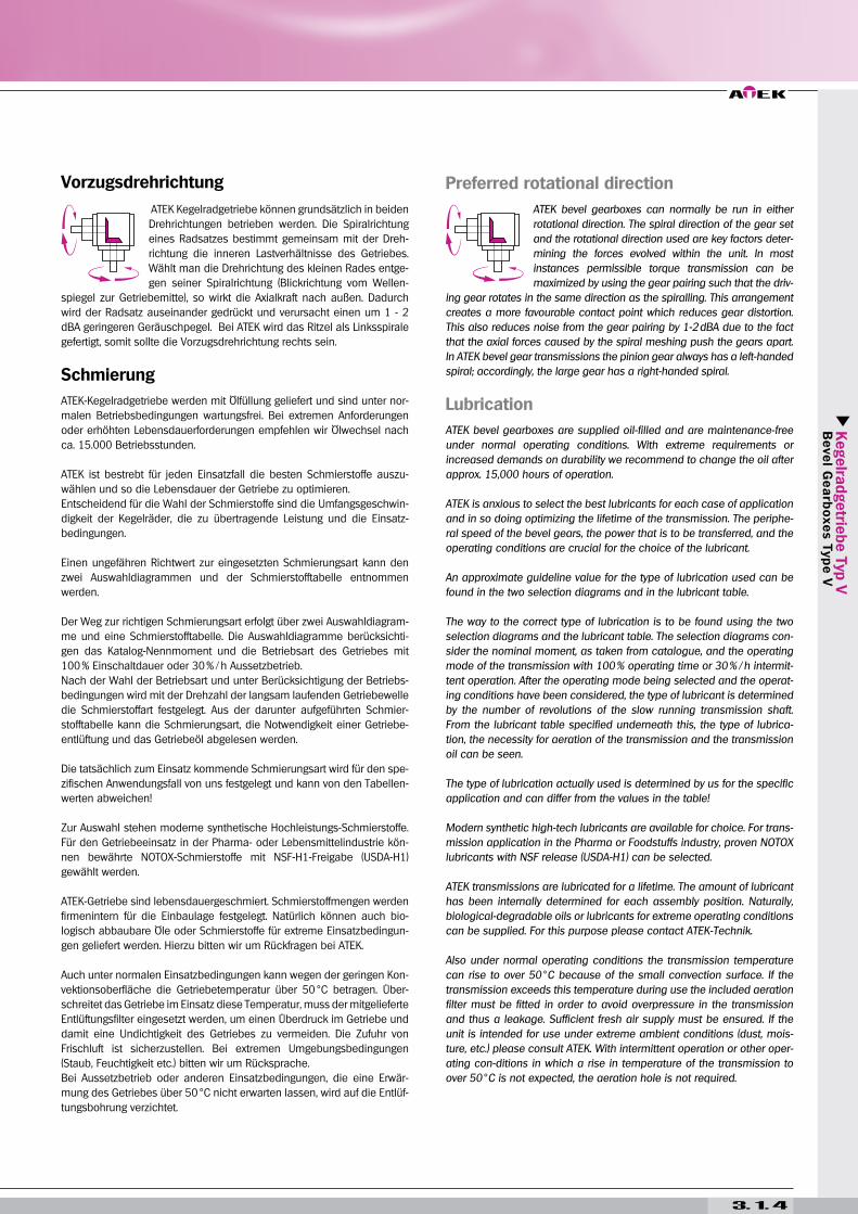
Vorzugsdrehrichtung
ATEK Kegelradgetriebe können grundsätzlich in beiden
Drehrichtungen betrieben werden. Die Spiralrichtung
eines Radsatzes bestimmt gemeinsam mit der Dreh-
richtung die inneren Lastverhältnisse des Getriebes.
Wählt man die Drehrichtung des kleinen Rades entge-
gen seiner Spiralrichtung (Blickrichtung vom Wellen-
spiegel zur Getriebemitte), so wirkt die Axialkraft nach außen. Dadurch
wird der Radsatz auseinander gedrückt und verursacht einen um 1 - 2
dBA geringeren Geräuschpegel. Bei ATEK wird das Ritzel als Linksspirale
gefertigt, somit sollte die Vorzugsdrehrichtung rechts sein.
Schmierung
ATEK-Kegelradgetriebe werden mit Ölfüllung geliefert und sind unter nor-
malen Betriebsbedingungen wartungsfrei. Bei extremen Anforderungen
oder erhöhten Lebensdauerforderungen empfehlen wir Ölwechsel nach
ca. 15.000 Betriebsstunden.
ATEK ist bestrebt für jeden Einsatzfall die besten Schmierstoffe auszu-
wählen und so die Lebensdauer der Getriebe zu optimieren.
Entscheidend für die Wahl der Schmierstoffe sind die Umfangsgeschwin-
digkeit der Kegelräder, die zu übertragende Leistung und die Einsatz-
bedingungen.
Einen ungefähren Richtwert zur eingesetzten Schmierungsart kann den
zwei Auswahldiagrammen und der Schmierstofftabelle entnommen
werden.
Der Weg zur richtigen Schmierungsart erfolgt über zwei Auswahldiagram-
me und eine Schmierstofftabelle. Die Auswahldiagramme berücksichti-
gen das Katalog-Nennmoment und die Betriebsart des Getriebes mit
100 % Einschaltdauer oder 30 % / h Aussetzbetrieb.
Nach der Wahl der Betriebsart und unter Berücksichtigung der Betriebs-
bedingungen wird mit der Drehzahl der langsam laufenden Getriebewelle
die Schmierstoffart festgelegt. Aus der darunter aufgeführten Schmier-
stofftabelle kann die Schmierungsart, die Notwendigkeit einer Getriebe-
entlüftung und das Getriebeöl abgelesen werden.
Die tatsächlich zum Einsatz kommende Schmierungsart wird für den spe-
zifischen Anwendungsfall von uns festgelegt und kann von den Tabellen-
werten abweichen!
Zur Auswahl stehen moderne synthetische Hochleistungs-Schmierstoffe.
Für den Getriebeeinsatz in der Pharma- oder Lebensmittelindustrie kön-
nen bewährte NOTOX-Schmierstoffe mit NSF-H1-Freigabe (USDA-H1)
gewählt werden.
ATEK-Getriebe sind lebensdauergeschmiert. Schmierstoffmengen werden
firmenintern für die Einbaulage festgelegt. Natürlich können auch bio-
logisch abbaubare Öle oder Schmierstoffe für extreme Einsatzbedingun-
gen geliefert werden. Hierzu bitten wir um Rückfragen bei ATEK.
Auch unter normalen Einsatzbedingungen kann wegen der geringen Kon-
vektionsoberfläche die Getriebetemperatur über 50 °C betragen. Über-
schreitet das Getriebe im Einsatz diese Temperatur, muss der mitgelieferte
Entlüftungsfilter eingesetzt werden, um einen Überdruck im Getriebe und
damit eine Undichtigkeit des Getriebes zu vermeiden. Die Zufuhr von
Frischluft ist sicherzustellen. Bei extremen Umgebungsbedingungen
(Staub, Feuchtigkeit etc.) bitten wir um Rücksprache.
Bei Aussetzbetrieb oder anderen Einsatzbedingungen, die eine Erwär-
mung des Getriebes über 50 °C nicht erwarten lassen, wird auf die Entlüf-
tungsbohrung verzichtet.
3. 1. 4
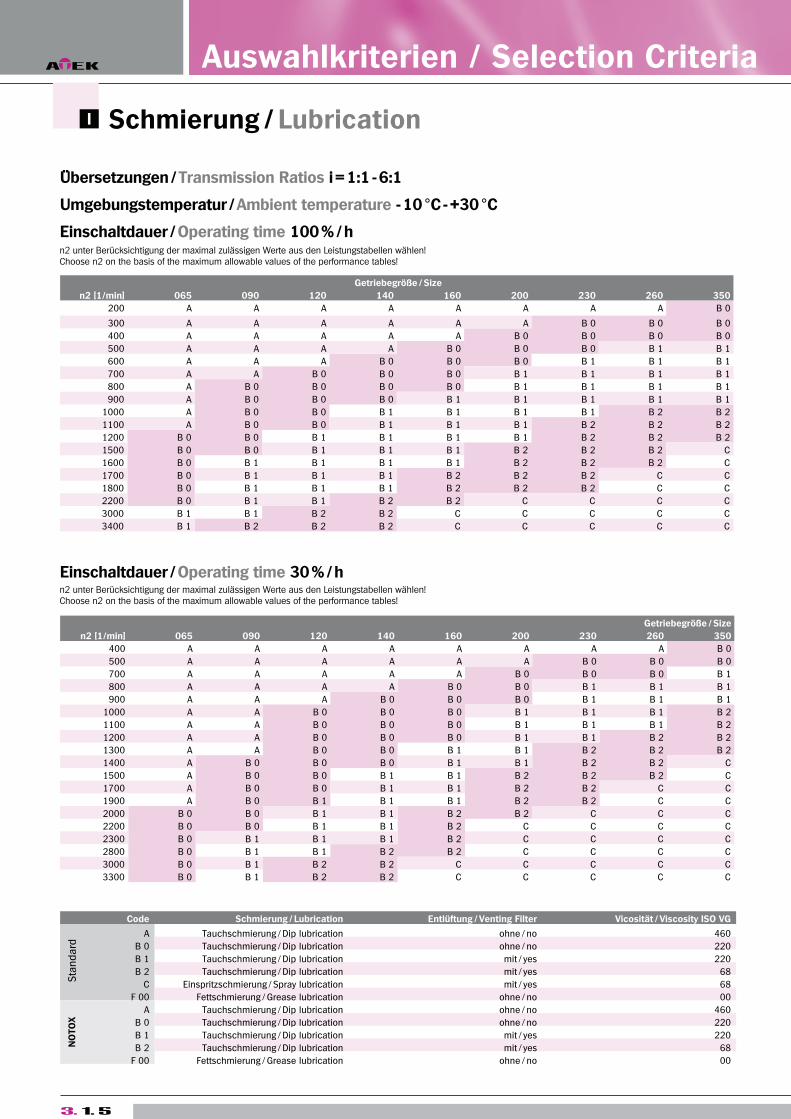
Schmierung / Lubrication
Übersetzungen / Transmission Ratios i = 1:1 - 6:1
Umgebungstemperatur / Ambient temperature - 10 °C - +30 °C
Einschaltdauer / Operating time 100 % / h
Code Schmierung / Lubrication Entlüftung / Venting Filter Vicosität / Viscosity ISO VG
Sta
nd
ard
A Tauchschmierung / Dip lubrication ohne / no 460
B 0 Tauchschmierung / Dip lubrication ohne / no 220
B 1 Tauchschmierung / Dip lubrication mit / yes 220
B 2 Tauchschmierung / Dip lubrication mit / yes 68
C Einspritzschmierung / Spray lubrication mit / yes 68
F 00 Fettschmierung / Grease lubrication ohne / no 00
NO
TO
X
A Tauchschmierung / Dip lubrication ohne / no 460
B 0 Tauchschmierung / Dip lubrication ohne / no 220
B 1 Tauchschmierung / Dip lubrication mit / yes 220
B 2 Tauchschmierung / Dip lubrication mit / yes 68
F 00 Fettschmierung / Grease lubrication ohne / no 00
3. 1. 5
Getriebegröße / Size
n2 [1/min] 065 090 120 140 160 200 230 260 350
200 A A A A A A A A B 0
300 A A A A A A B 0 B 0 B 0
400 A A A A A B 0 B 0 B 0 B 0
500 A A A A B 0 B 0 B 0 B 1 B 1
600 A A A B 0 B 0 B 0 B 1 B 1 B 1
700 A A B 0 B 0 B 0 B 1 B 1 B 1 B 1
800 A B 0 B 0 B 0 B 0 B 1 B 1 B 1 B 1
900 A B 0 B 0 B 0 B 1 B 1 B 1 B 1 B 1
1000 A B 0 B 0 B 1 B 1 B 1 B 1 B 2 B 2
1100 A B 0 B 0 B 1 B 1 B 1 B 2 B 2 B 2
1200 B 0 B 0 B 1 B 1 B 1 B 1 B 2 B 2 B 2
1500 B 0 B 0 B 1 B 1 B 1 B 2 B 2 B 2 C
1600 B 0 B 1 B 1 B 1 B 1 B 2 B 2 B 2 C
1700 B 0 B 1 B 1 B 1 B 2 B 2 B 2 C C
1800 B 0 B 1 B 1 B 1 B 2 B 2 B 2 C C
2200 B 0 B 1 B 1 B 2 B 2 C C C C
3000 B 1 B 1 B 2 B 2 C C C C C
3400 B 1 B 2 B 2 B 2 C C C C C
Getriebegröße / Size
n2 [1/min] 065 090 120 140 160 200 230 260 350
400 A A A A A A A A B 0
500 A A A A A A B 0 B 0 B 0
700 A A A A A B 0 B 0 B 0 B 1
800 A A A A B 0 B 0 B 1 B 1 B 1
900 A A A B 0 B 0 B 0 B 1 B 1 B 1
1000 A A B 0 B 0 B 0 B 1 B 1 B 1 B 2
1100 A A B 0 B 0 B 0 B 1 B 1 B 1 B 2
1200 A A B 0 B 0 B 0 B 1 B 1 B 2 B 2
1300 A A B 0 B 0 B 1 B 1 B 2 B 2 B 2
1400 A B 0 B 0 B 0 B 1 B 1 B 2 B 2 C
1500 A B 0 B 0 B 1 B 1 B 2 B 2 B 2 C
1700 A B 0 B 0 B 1 B 1 B 2 B 2 C C
1900 A B 0 B 1 B 1 B 1 B 2 B 2 C C
2000 B 0 B 0 B 1 B 1 B 2 B 2 C C C
2200 B 0 B 0 B 1 B 1 B 2 C C C C
2300 B 0 B 1 B 1 B 1 B 2 C C C C
2800 B 0 B 1 B 1 B 2 B 2 C C C C
3000 B 0 B 1 B 2 B 2 C C C C C
3300 B 0 B 1 B 2 B 2 C C C C C
Einschaltdauer / Operating time 30 % / h
Auswahlkriterien / Selection Criteria
n2 unter Berücksichtigung der maximal zulässigen Werte aus den Leistungstabellen wählen!Choose n2 on the basis of the maximum allowable values of the performance tables!
n2 unter Berücksichtigung der maximal zulässigen Werte aus den Leistungstabellen wählen!Choose n2 on the basis of the maximum allowable values of the performance tables!
Kegelra
dgetrie
be T
yp V
B
eve
l Ge
arb
oxe
s T
yp
e V
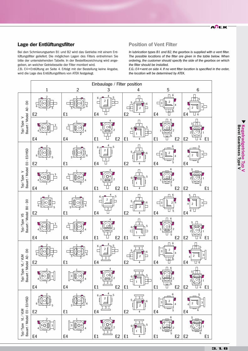
Position of Vent Filter
In lubrication types B1 and B2, the gearbox is supplied with a vent filter.
The possible locations of the filter are given in the table below. When
ordering, the customer should specify the side of the gearbox on which
the filter should be installed.
E.G.: E4 = vent on side 4. If no vent filter location is specified in the order,
the location will be determined by ATEK.
Lage der Entlüftungsfilter
Bei den Schmierungsarten B1 und B2 wird das Getriebe mit einem Ent-
lüftungsfilter geliefert. Die möglichen Lagen des Filters entnehmen Sie
bitte der untenstehenden Tabelle. In der Bestellbezeichnung wird ange-
geben, an welcher Getriebeseite der Filter montiert wird.
Z.B.: E4 = Entlüftung an Seite 4. Erfolgt mit der Bestellung keine Angabe,
wird die Lage des Entlüftungsfilters von ATEK festgelegt.
3. 1. 6
Kegelra
dgetrie
be T
yp V
B
eve
l Ge
arb
oxe
s T
yp
e V
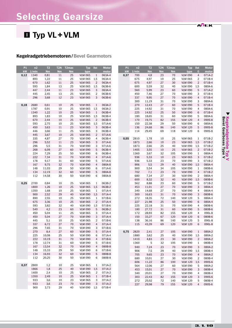
Kegelradgetriebemotoren / Bevel Gearmotors
Typ VL + VLM
3. 1. 10
P1 n2 T2 T2N T2max Typ iIst Motor
kW 1/min Nm Nm Nm type motor
0,12 1340 0,81 11 25 VLM 065 1 063A-4
893 1,22 11 25 VLM 065 1,5 063A-4
670 1,62 11 25 VLM 065 2 063A-4
593 1,84 13 25 VLM 065 1,5 063B-6
447 2,44 11 23 VLM 065 3 063A-4
445 2,45 13 25 VLM 065 2 063B-6
296 3,68 12 23 VLM 065 3 063B-6
0,18 2680 0,61 10 25 VLM 065 1 063A-2
1787 0,91 10 25 VLM 065 1,5 063A-2
1340 1,22 10 25 VLM 065 1 063B-4
893 1,83 10 25 VLM 065 1,5 063B-4
670 2,44 10 25 VLM 065 2 063B-4
593 2,75 10 25 VLM 065 1,5 071A-6
450 3,63 11 23 VLM 065 3 063B-4
446 3,66 11 25 VLM 065 3 063B-4
445 3,67 10 25 VLM 065 2 071A-6
335 4,87 27 70 VLM 090 4 063B-4
296 5,52 11 23 VLM 065 3 071A-6
296 5,5 31 70 VLM 090 3 071A-6
268 6,09 27 60 VLM 090 5 063B-4
224 7,29 25 50 VLM 090 6 063B-4
222 7,34 31 70 VLM 090 4 071A-6
178 9,17 31 60 VLM 090 5 071A-6
167 9,75 32 70 VLM 090 4 080A-8
148 11,03 29 50 VLM 090 6 071A-6
134 12,19 32 60 VLM 090 5 080A-8
112 14,58 30 50 VLM 090 6 080A-8
0,25 2700 0,84 10 25 VLM 065 1 063B-2
1800 1,26 10 25 VLM 065 1,5 063B-2
1350 1,68 10 25 VLM 065 1 071A-4
900 2,52 29 40 VLM 090 1,5 071A-4
890 2,55 10 25 VLM 065 1 071B-6
675 3,36 10 25 VLM 065 2 071A-4
593 3,82 32 40 VLM 090 1,5 071B-6
540 4,2 23 60 VLM 090 5 063B-2
450 5,04 11 25 VLM 065 3 071A-4
450 5,04 27 70 VLM 090 3 071A-4
445 5,1 10 25 VLM 065 2 071B-6
337 6,72 27 70 VLM 090 4 071A-4
296 7,65 31 70 VLM 090 3 071B-6
270 8,4 27 60 VLM 090 5 071A-4
225 10,08 25 50 VLM 090 6 071A-4
222 10,19 31 70 VLM 090 4 071B-6
178 12,74 31 60 VLM 090 5 071B-6
167 13,54 32 70 VLM 090 4 080B-8
148 15,33 29 50 VLM 090 6 071B-6
134 16,93 32 60 VLM 090 5 080B-8
112 20,25 30 50 VLM 090 6 080B-8
0,37 2800 1,2 10 25 VLM 065 1 071A-2
1866 1,8 25 40 VLM 090 1,5 071A-2
1400 2,4 10 25 VLM 065 2 071A-2
1350 2,49 10 25 VLM 065 1 071B-4
933 3,6 10 23 VLM 065 3 071A-2
933 3,6 23 70 VLM 090 3 071A-2
900 3,73 29 40 VLM 090 1,5 071B-4
P1 n2 T2 T2N T2max Typ iIst Motor
kW 1/min Nm Nm Nm type 0 motor
0,37 700 4,8 23 70 VLM 090 4 071A-2
675 4,97 10 25 VLM 065 2 071B-4
675 4,97 27 30 VLM 090 2 071B-4
600 5,59 32 40 VLM 090 1,5 080A-6
560 5,99 23 60 VLM 090 5 071A-2
450 7,46 27 70 VLM 090 3 071B-4
337 9,95 27 70 VLM 090 4 071B-4
300 11,19 31 70 VLM 090 3 080A-6
270 12,43 27 60 VLM 090 5 071B-4
225 14,92 31 70 VLM 090 4 080A-6
225 14,92 25 50 VLM 090 6 071B-4
180 18,65 31 60 VLM 090 5 080A-6
170 19,75 82 155 VLM 120 4 090S-8
150 22,38 29 50 VLM 090 6 080A-6
136 24,68 86 140 VLM 120 5 090S-8
114 29,45 69 118 VLM 120 6 090S-8
0,55 2810 1,78 10 25 VLM 065 1 071B-2
1873 2,66 10 23 VLM 065 1,5 071B-2
1873 2,66 25 40 VLM 090 1,5 071B-2
1405 3,55 10 25 VLM 065 2 071B-2
1360 3,67 32 105 VLM 090 1 080A-4
936 5,33 10 23 VLM 065 3 071B-2
936 5,33 23 70 VLM 090 3 071B-2
906 5,5 29 40 VLM 090 1,5 080A-4
900 5,54 34 105 VLM 090 1 080B-6
702 7,1 23 70 VLM 090 4 071B-2
680 7,34 27 30 VLM 090 2 080A-4
600 8,32 32 40 VLM 090 1,5 080B-6
562 8,88 23 60 VLM 090 5 071B-2
453 11,01 27 70 VLM 090 3 080A-4
340 14,68 27 70 VLM 090 4 080A-4
300 16,63 31 70 VLM 090 3 080B-6
272 18,35 72 140 VLM 120 5 080A-4
227 21,98 25 50 VLM 090 6 080A-4
225 22,18 31 70 VLM 090 4 080B-6
180 27,72 31 60 VLM 090 5 080B-6
172 28,93 82 155 VLM 120 4 090L-8
150 33,27 67 120 VLM 120 6 080B-6
138 36,16 86 140 VLM 120 5 090L-8
115 43,39 69 120 VLM 120 6 090L-8
0,75 2820 2,41 27 105 VLM 090 1 080A-2
1880 3,62 25 40 VLM 090 1,5 080A-2
1410 4,83 23 30 VLM 090 2 080A-2
1360 5 32 105 VLM 090 1 080B-4
940 7,24 23 70 VLM 090 3 080A-2
906 7,5 29 40 VLM 090 1,5 080B-4
705 9,65 23 70 VLM 090 4 080A-2
680 10,01 27 30 VLM 090 2 080B-4
606 11,22 86 100 VLM 120 1,5 090S-6
564 12,06 27 60 VLM 090 5 080A-2
453 15,01 27 70 VLM 090 3 080B-4
340 20,01 27 70 VLM 090 4 080B-4
303 22,43 82 155 VLM 120 3 090S-6
272 25,02 72 140 VLM 120 5 080B-4
227 29,98 79 155 VLM 120 4 090S-6
Selecting Gearsize
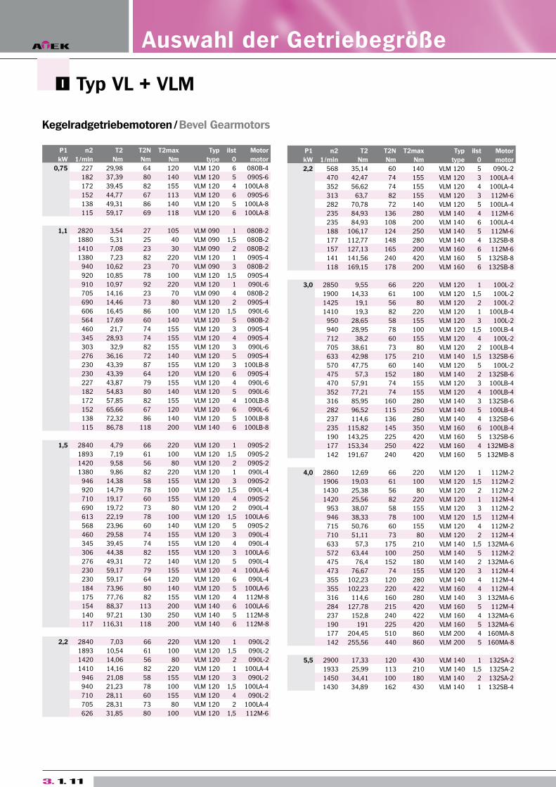
Typ VL + VLM
Kegelradgetriebemotoren / Bevel Gearmotors
3. 1. 11
P1 n2 T2 T2N T2max Typ iIst Motor
kW 1/min Nm Nm Nm type 0 motor
0,75 227 29,98 64 120 VLM 120 6 080B-4
182 37,39 80 140 VLM 120 5 090S-6
172 39,45 82 155 VLM 120 4 100LA-8
152 44,77 67 113 VLM 120 6 090S-6
138 49,31 86 140 VLM 120 5 100LA-8
115 59,17 69 118 VLM 120 6 100LA-8
1,1 2820 3,54 27 105 VLM 090 1 080B-2
1880 5,31 25 40 VLM 090 1,5 080B-2
1410 7,08 23 30 VLM 090 2 080B-2
1380 7,23 82 220 VLM 120 1 090S-4
940 10,62 23 70 VLM 090 3 080B-2
920 10,85 78 100 VLM 120 1,5 090S-4
910 10,97 92 220 VLM 120 1 090L-6
705 14,16 23 70 VLM 090 4 080B-2
690 14,46 73 80 VLM 120 2 090S-4
606 16,45 86 100 VLM 120 1,5 090L-6
564 17,69 60 140 VLM 120 5 080B-2
460 21,7 74 155 VLM 120 3 090S-4
345 28,93 74 155 VLM 120 4 090S-4
303 32,9 82 155 VLM 120 3 090L-6
276 36,16 72 140 VLM 120 5 090S-4
230 43,39 87 155 VLM 120 3 100LB-8
230 43,39 64 120 VLM 120 6 090S-4
227 43,87 79 155 VLM 120 4 090L-6
182 54,83 80 140 VLM 120 5 090L-6
172 57,85 82 155 VLM 120 4 100LB-8
152 65,66 67 120 VLM 120 6 090L-6
138 72,32 86 140 VLM 120 5 100LB-8
115 86,78 118 200 VLM 140 6 100LB-8
1,5 2840 4,79 66 220 VLM 120 1 090S-2
1893 7,19 61 100 VLM 120 1,5 090S-2
1420 9,58 56 80 VLM 120 2 090S-2
1380 9,86 82 220 VLM 120 1 090L-4
946 14,38 58 155 VLM 120 3 090S-2
920 14,79 78 100 VLM 120 1,5 090L-4
710 19,17 60 155 VLM 120 4 090S-2
690 19,72 73 80 VLM 120 2 090L-4
613 22,19 78 100 VLM 120 1,5 100LA-6
568 23,96 60 140 VLM 120 5 090S-2
460 29,58 74 155 VLM 120 3 090L-4
345 39,45 74 155 VLM 120 4 090L-4
306 44,38 82 155 VLM 120 3 100LA-6
276 49,31 72 140 VLM 120 5 090L-4
230 59,17 79 155 VLM 120 4 100LA-6
230 59,17 64 120 VLM 120 6 090L-4
184 73,96 80 140 VLM 120 5 100LA-6
175 77,76 82 155 VLM 120 4 112M-8
154 88,37 113 200 VLM 140 6 100LA-6
140 97,21 130 250 VLM 140 5 112M-8
117 116,31 118 200 VLM 140 6 112M-8
2,2 2840 7,03 66 220 VLM 120 1 090L-2
1893 10,54 61 100 VLM 120 1,5 090L-2
1420 14,06 56 80 VLM 120 2 090L-2
1410 14,16 82 220 VLM 120 1 100LA-4
946 21,08 58 155 VLM 120 3 090L-2
940 21,23 78 100 VLM 120 1,5 100LA-4
710 28,11 60 155 VLM 120 4 090L-2
705 28,31 73 80 VLM 120 2 100LA-4
626 31,85 80 100 VLM 120 1,5 112M-6
P1 n2 T2 T2N T2max Typ iIst Motor
kW 1/min Nm Nm Nm type 0 motor
2,2 568 35,14 60 140 VLM 120 5 090L-2
470 42,47 74 155 VLM 120 3 100LA-4
352 56,62 74 155 VLM 120 4 100LA-4
313 63,7 82 155 VLM 120 3 112M-6
282 70,78 72 140 VLM 120 5 100LA-4
235 84,93 136 280 VLM 140 4 112M-6
235 84,93 108 200 VLM 140 6 100LA-4
188 106,17 124 250 VLM 140 5 112M-6
177 112,77 148 280 VLM 140 4 132SB-8
157 127,13 165 200 VLM 160 6 112M-6
141 141,56 240 420 VLM 160 5 132SB-8
118 169,15 178 200 VLM 160 6 132SB-8
3,0 2850 9,55 66 220 VLM 120 1 100L-2
1900 14,33 61 100 VLM 120 1,5 100L-2
1425 19,1 56 80 VLM 120 2 100L-2
1410 19,3 82 220 VLM 120 1 100LB-4
950 28,65 58 155 VLM 120 3 100L-2
940 28,95 78 100 VLM 120 1,5 100LB-4
712 38,2 60 155 VLM 120 4 100L-2
705 38,61 73 80 VLM 120 2 100LB-4
633 42,98 175 210 VLM 140 1,5 132SB-6
570 47,75 60 140 VLM 120 5 100L-2
475 57,3 152 180 VLM 140 2 132SB-6
470 57,91 74 155 VLM 120 3 100LB-4
352 77,21 74 155 VLM 120 4 100LB-4
316 85,95 160 280 VLM 140 3 132SB-6
282 96,52 115 250 VLM 140 5 100LB-4
237 114,6 136 280 VLM 140 4 132SB-6
235 115,82 145 350 VLM 160 6 100LB-4
190 143,25 225 420 VLM 160 5 132SB-6
177 153,34 250 422 VLM 160 4 132MB-8
142 191,67 240 420 VLM 160 5 132MB-8
4,0 2860 12,69 66 220 VLM 120 1 112M-2
1906 19,03 61 100 VLM 120 1,5 112M-2
1430 25,38 56 80 VLM 120 2 112M-2
1420 25,56 82 220 VLM 120 1 112M-4
953 38,07 58 155 VLM 120 3 112M-2
946 38,33 78 100 VLM 120 1,5 112M-4
715 50,76 60 155 VLM 120 4 112M-2
710 51,11 73 80 VLM 120 2 112M-4
633 57,3 175 210 VLM 140 1,5 132MA-6
572 63,44 100 250 VLM 140 5 112M-2
475 76,4 152 180 VLM 140 2 132MA-6
473 76,67 74 155 VLM 120 3 112M-4
355 102,23 120 280 VLM 140 4 112M-4
355 102,23 220 422 VLM 160 4 112M-4
316 114,6 160 280 VLM 140 3 132MA-6
284 127,78 215 420 VLM 160 5 112M-4
237 152,8 240 422 VLM 160 4 132MA-6
190 191 225 420 VLM 160 5 132MA-6
177 204,45 510 860 VLM 200 4 160MA-8
142 255,56 440 860 VLM 200 5 160MA-8
5,5 2900 17,33 120 430 VLM 140 1 132SA-2
1933 25,99 113 210 VLM 140 1,5 132SA-2
1450 34,41 100 180 VLM 140 2 132SA-2
1430 34,89 162 430 VLM 140 1 132SB-4
Auswahl der Getriebegröße
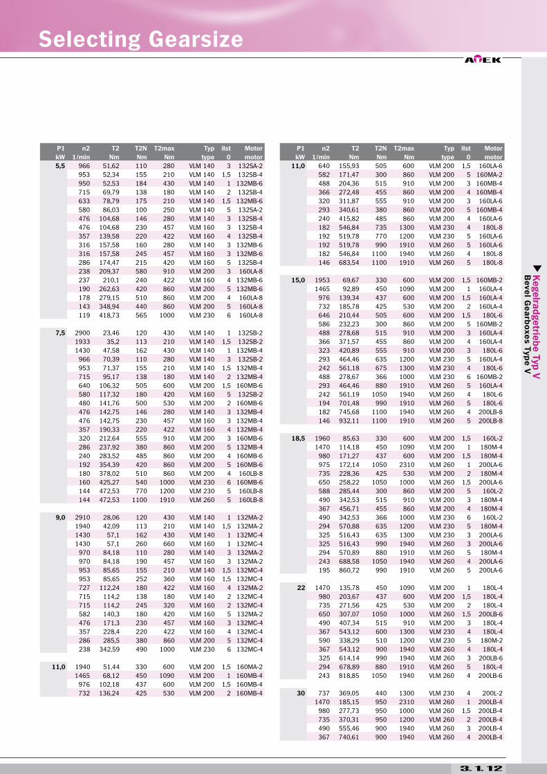
Kegelra
dgetrie
be T
yp V
B
eve
l Ge
arb
oxe
s T
yp
e V
3. 1. 12
Selecting Gearsize
P1 n2 T2 T2N T2max Typ iIst Motor
kW 1/min Nm Nm Nm type 0 motor
5,5 966 51,62 110 280 VLM 140 3 132SA-2
953 52,34 155 210 VLM 140 1,5 132SB-4
950 52,53 184 430 VLM 140 1 132MB-6
715 69,79 138 180 VLM 140 2 132SB-4
633 78,79 175 210 VLM 140 1,5 132MB-6
580 86,03 100 250 VLM 140 5 132SA-2
476 104,68 146 280 VLM 140 3 132SB-4
476 104,68 230 457 VLM 160 3 132SB-4
357 139,58 220 422 VLM 160 4 132SB-4
316 157,58 160 280 VLM 140 3 132MB-6
316 157,58 245 457 VLM 160 3 132MB-6
286 174,47 215 420 VLM 160 5 132SB-4
238 209,37 580 910 VLM 200 3 160LA-8
237 210,1 240 422 VLM 160 4 132MB-6
190 262,63 420 860 VLM 200 5 132MB-6
178 279,15 510 860 VLM 200 4 160LA-8
143 348,94 440 860 VLM 200 5 160LA-8
119 418,73 565 1000 VLM 230 6 160LA-8
7,5 2900 23,46 120 430 VLM 140 1 132SB-2
1933 35,2 113 210 VLM 140 1,5 132SB-2
1430 47,58 162 430 VLM 140 1 132MB-4
966 70,39 110 280 VLM 140 3 132SB-2
953 71,37 155 210 VLM 140 1,5 132MB-4
715 95,17 138 180 VLM 140 2 132MB-4
640 106,32 505 600 VLM 200 1,5 160MB-6
580 117,32 180 420 VLM 160 5 132SB-2
480 141,76 500 530 VLM 200 2 160MB-6
476 142,75 146 280 VLM 140 3 132MB-4
476 142,75 230 457 VLM 160 3 132MB-4
357 190,33 220 422 VLM 160 4 132MB-4
320 212,64 555 910 VLM 200 3 160MB-6
286 237,92 380 860 VLM 200 5 132MB-4
240 283,52 485 860 VLM 200 4 160MB-6
192 354,39 420 860 VLM 200 5 160MB-6
180 378,02 510 860 VLM 200 4 160LB-8
160 425,27 540 1000 VLM 230 6 160MB-6
144 472,53 770 1200 VLM 230 5 160LB-8
144 472,53 1100 1910 VLM 260 5 160LB-8
9,0 2910 28,06 120 430 VLM 140 1 132MA-2
1940 42,09 113 210 VLM 140 1,5 132MA-2
1430 57,1 162 430 VLM 140 1 132MC-4
1430 57,1 260 660 VLM 160 1 132MC-4
970 84,18 110 280 VLM 140 3 132MA-2
970 84,18 190 457 VLM 160 3 132MA-2
953 85,65 155 210 VLM 140 1,5 132MC-4
953 85,65 252 360 VLM 160 1,5 132MC-4
727 112,24 180 422 VLM 160 4 132MA-2
715 114,2 138 180 VLM 140 2 132MC-4
715 114,2 245 320 VLM 160 2 132MC-4
582 140,3 180 420 VLM 160 5 132MA-2
476 171,3 230 457 VLM 160 3 132MC-4
357 228,4 220 422 VLM 160 4 132MC-4
286 285,5 380 860 VLM 200 5 132MC-4
238 342,59 490 1000 VLM 230 6 132MC-4
11,0 1940 51,44 330 600 VLM 200 1,5 160MA-2
1465 68,12 450 1090 VLM 200 1 160MB-4
976 102,18 437 600 VLM 200 1,5 160MB-4
732 136,24 425 530 VLM 200 2 160MB-4
P1 n2 T2 T2N T2max Typ iIst Motor
kW 1/min Nm Nm Nm type 0 motor
11,0 640 155,93 505 600 VLM 200 1,5 160LA-6
582 171,47 300 860 VLM 200 5 160MA-2
488 204,36 515 910 VLM 200 3 160MB-4
366 272,48 455 860 VLM 200 4 160MB-4
320 311,87 555 910 VLM 200 3 160LA-6
293 340,61 380 860 VLM 200 5 160MB-4
240 415,82 485 860 VLM 200 4 160LA-6
182 546,84 735 1300 VLM 230 4 180L-8
192 519,78 770 1200 VLM 230 5 160LA-6
192 519,78 990 1910 VLM 260 5 160LA-6
182 546,84 1100 1940 VLM 260 4 180L-8
146 683,54 1100 1910 VLM 260 5 180L-8
15,0 1953 69,67 330 600 VLM 200 1,5 160MB-2
1465 92,89 450 1090 VLM 200 1 160LA-4
976 139,34 437 600 VLM 200 1,5 160LA-4
732 185,78 425 530 VLM 200 2 160LA-4
646 210,44 505 600 VLM 200 1,5 180L-6
586 232,23 300 860 VLM 200 5 160MB-2
488 278,68 515 910 VLM 200 3 160LA-4
366 371,57 455 860 VLM 200 4 160LA-4
323 420,89 555 910 VLM 200 3 180L-6
293 464,46 635 1200 VLM 230 5 160LA-4
242 561,18 675 1300 VLM 230 4 180L-6
488 278,67 366 1000 VLM 230 6 160MB-2
293 464,46 880 1910 VLM 260 5 160LA-4
242 561,19 1050 1940 VLM 260 4 180L-6
194 701,48 990 1910 VLM 260 5 180L-6
182 745,68 1100 1940 VLM 260 4 200LB-8
146 932,11 1100 1910 VLM 260 5 200LB-8
18,5 1960 85,63 330 600 VLM 200 1,5 160L-2
1470 114,18 450 1090 VLM 200 1 180M-4
980 171,27 437 600 VLM 200 1,5 180M-4
975 172,14 1050 2310 VLM 260 1 200LA-6
735 228,36 425 530 VLM 200 2 180M-4
650 258,22 1050 1000 VLM 260 1,5 200LA-6
588 285,44 300 860 VLM 200 5 160L-2
490 342,53 515 910 VLM 200 3 180M-4
367 456,71 455 860 VLM 200 4 180M-4
490 342,53 366 1000 VLM 230 6 160L-2
294 570,88 635 1200 VLM 230 5 180M-4
325 516,43 635 1300 VLM 230 3 200LA-6
325 516,43 990 1940 VLM 260 3 200LA-6
294 570,89 880 1910 VLM 260 5 180M-4
243 688,58 1050 1940 VLM 260 4 200LA-6
195 860,72 990 1910 VLM 260 5 200LA-6
22 1470 135,78 450 1090 VLM 200 1 180L-4
980 203,67 437 600 VLM 200 1,5 180L-4
735 271,56 425 530 VLM 200 2 180L-4
650 307,07 1050 1000 VLM 260 1,5 200LB-6
490 407,34 515 910 VLM 200 3 180L-4
367 543,12 600 1300 VLM 230 4 180L-4
590 338,29 510 1200 VLM 230 5 180M-2
367 543,12 900 1940 VLM 260 4 180L-4
325 614,14 990 1940 VLM 260 3 200LB-6
294 678,89 880 1910 VLM 260 5 180L-4
243 818,85 1050 1940 VLM 260 4 200LB-6
30 737 369,05 440 1300 VLM 230 4 200L-2
1470 185,15 950 2310 VLM 260 1 200LB-4
980 277,73 950 1000 VLM 260 1,5 200LB-4
735 370,31 950 1200 VLM 260 2 200LB-4
490 555,46 900 1940 VLM 260 3 200LB-4
367 740,61 900 1940 VLM 260 4 200LB-4
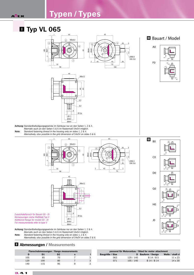
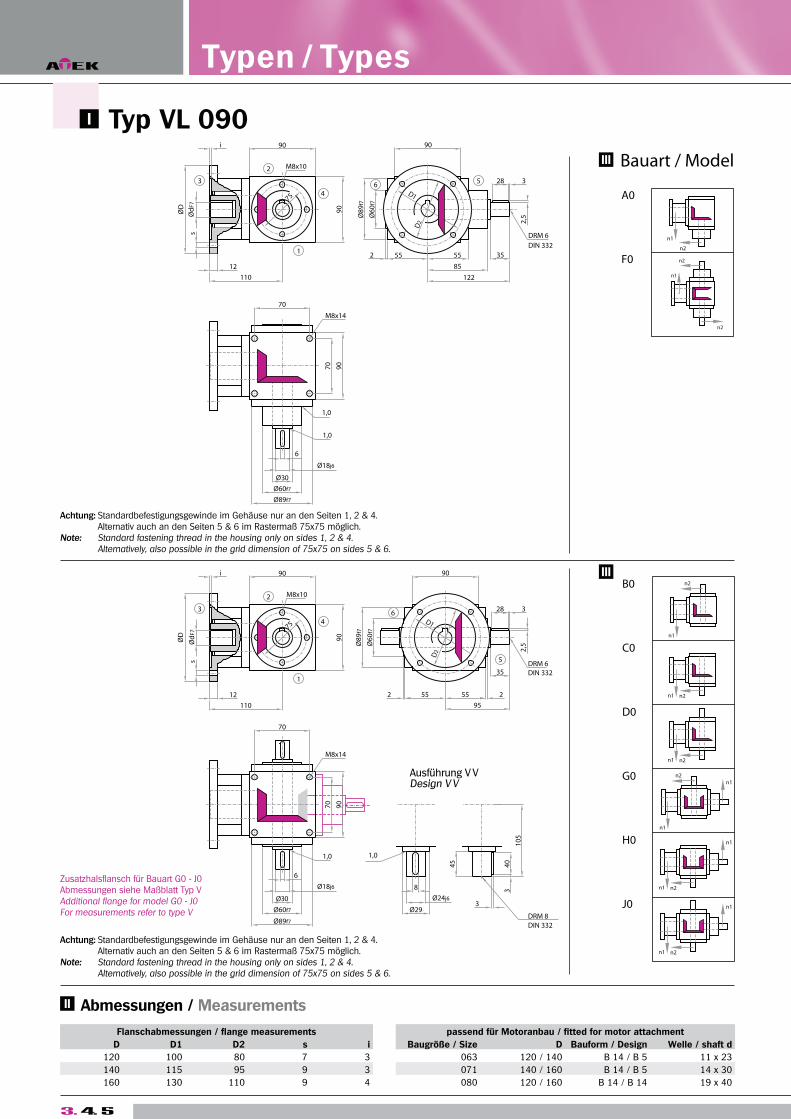
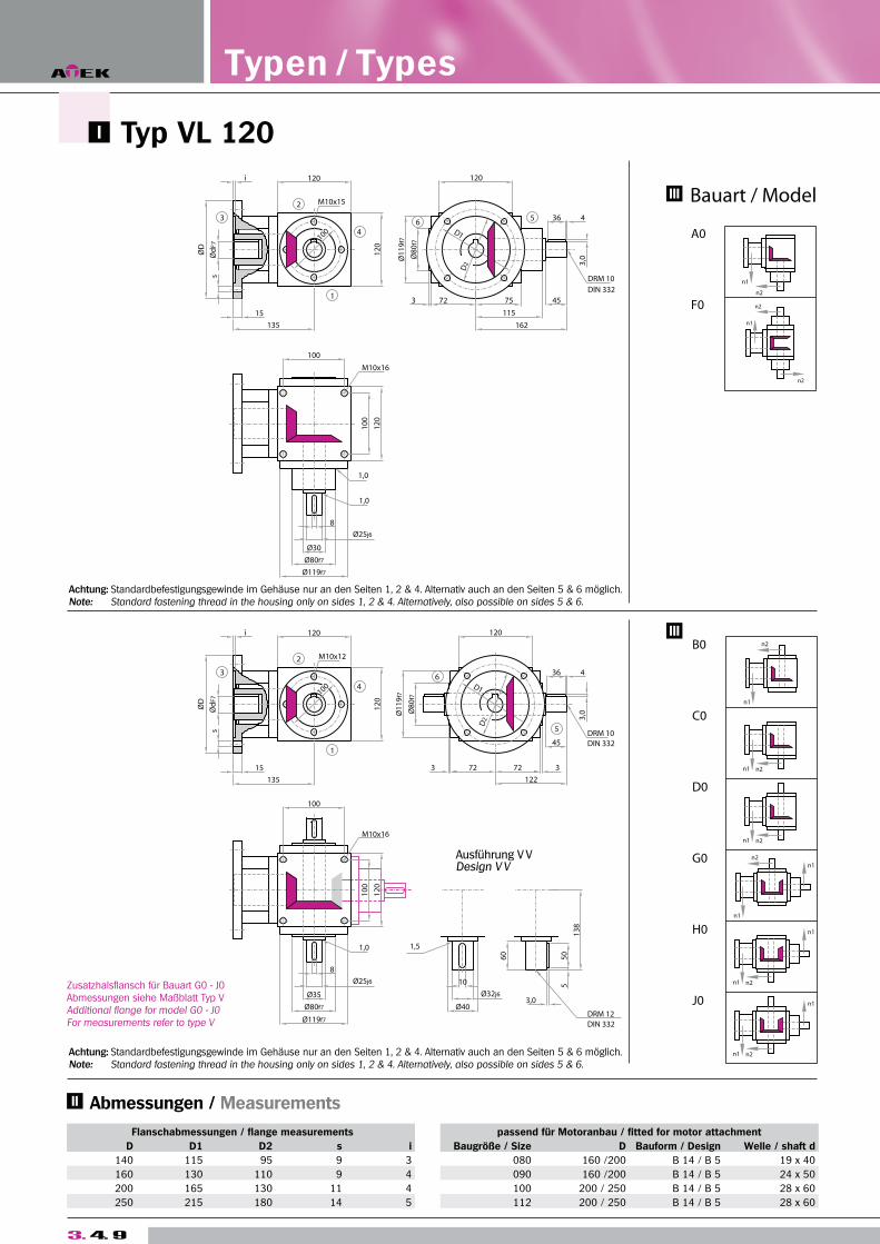
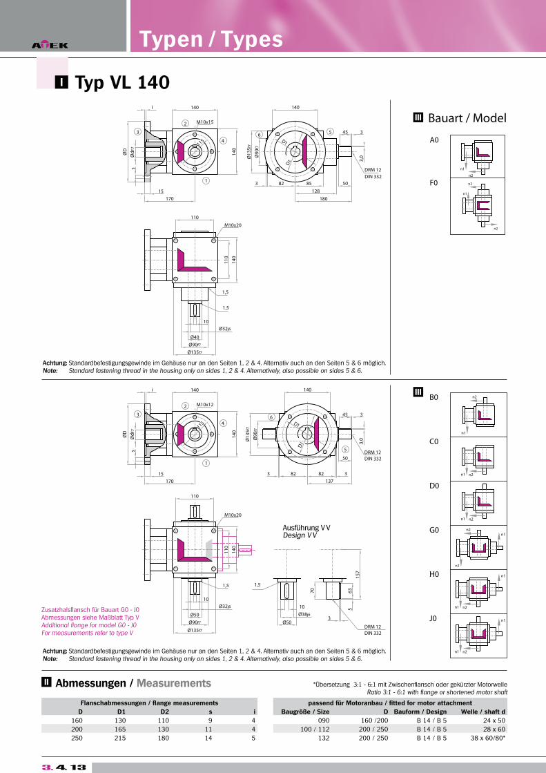
Abmessungen / Measurements
3. 4. 1
Zusatzhalsflansch für Bauart G0 - J0 Abmessungen siehe Maßblatt Typ VAdditional flange for model G0 - J0For measurements refer to type V
Flanschabmessungen / flange measurements passend für Motoranbau / fitted for motor attachment
D D1 D2 s i Baugröße / Size D Bauform / Design Welle / shaft d
105 85 70 7 3 063 120 / 140 B 14 / B 5 11 x 23
120 100 80 7 3 071 105 / 140 B 14 / B 14 14 x 30
140 115 95 9 3
Typen / Types
Typ VL 065
Achtung: Standardbefestigungsgewinde im Gehäuse nur an den Seiten 1, 2 & 4. Alternativ auch an den Seiten 5 & 6 im Rastermaß 54x54 möglich.Note: Standard fastening thread in the housing only on sides 1, 2 & 4. Alternatively, also possible in the grid dimension of 54x54 on sides 5 & 6.
Achtung: Standardbefestigungsgewinde im Gehäuse nur an den Seiten 1, 2 & 4. Alternativ auch an den Seiten 5 & 6 im Rastermaß 54x54 möglich.Note: Standard fastening thread in the housing only on sides 1, 2 & 4. Alternatively, also possible in the grid dimension of 54x54 on sides 5 & 6.
Kegelra
dgetrie
be T
yp V
B
eve
l Ge
arb
oxe
s T
yp
e V
T2 n2 (1/min) n2 (1/min)
Nm 3000 1000 500 250 100 50 3000 1000 500 250 100 50
< 12 180 250 300 350 450 550 300 400 500 650 750 900
> 12 150 210 250 290 380 460 250 330 420 540 630 750
3. 4. 2
Abzug für Motorwellenbohrung / Reduction for motor shaft boret
Ø d x l 09x20 = -0,0013 11x23 = -0,0032 14x30 = -0,0107
i = 1:1 P1N 1,5:1 P1N 2:1 P1N 3:1 P1N
n1 n2 T2N n2 T2N n2 T2N n2 T2N
3000 3000 3,31 2000 2,20 1500 1,65 1000 1,10
10,00 10,00 10,00 10,00
2400 2400 2,65 1600 1,76 1200 1,32 800 0,88
10,00 10,00 10,00 10,00
1500 1500 1,82 1000 1,21 750 0,91 500 0,61
11,00 11,00 11,00 11,00
1000 1000 1,32 667 0,88 500 0,66 333 0,44
12,00 12,00 12,00 12,00
750 750 1,07 500 0,72 375 0,54 250 0,33
13,00 13,00 13,00 12,00
500 500 0,83 333 0,55 250 0,41 167 0,24
15,00 15,00 15,00 13,00
250 250 0,47 167 0,31 125 0,23 83 0,12
17,00 17,00 17,00 13,00
50 50 0,10 33 0,07 25 0,05 17 0,03
18,00 18,00 18,00 14,00
P1Nt 1,60 1,60 1,60 1,60
T2max 25,00 25,00 25,00 23,00
Bauart Übersetzung / Transmission Ratios
Model 1:1 1,5:1 2:1 3:1
A0 0,6206 0,4859 0,4363 0,3767
F0 0,8150 0,5723 0,4849 0,3983
B0, C0 0,6549 0,5564 0,4854 0,3732
D0 0,6648 0,5608 0,4879 0,3743
G0, H0 0,8493 0,7106 0,6207 0,4552
J0 0,8592 0,7150 0,6232 0,4563
Bauart ca. Gewicht
Model app. Weight
A0 3,3
F0 3,7
B0, C0 3,2
D0 3,3
G0, H0 3,6
J0 3,7
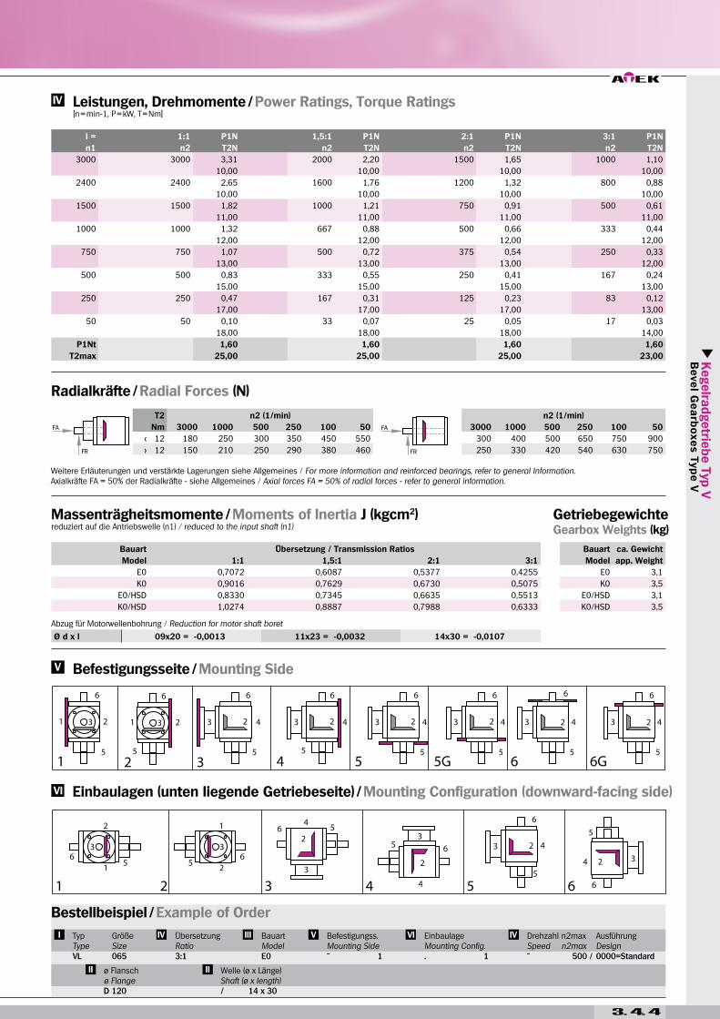
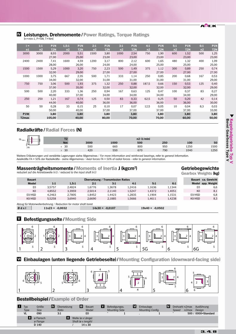
Massenträgheitsmomente / Moments of Inertia J (kgcm2)reduziert auf die Antriebswelle (n1) / reduced to the input shaft (n1)
Getriebegewichte Gearbox Weights (kg)
Radialkräfte / Radial Forces (N)
Leistungen, Drehmomente / Power Ratings, Torque Ratings [n = min-1, P = kW, T = Nm]
Einbaulagen (unten liegende Getriebeseite) / Mounting Configuration (downward-facing side)
Befestigungsseite / Mounting Side
Weitere Erläuterungen und verstärkte Lagerungen siehe Allgemeines / For more information and reinforced bearings, refer to general Information.Axialkräfte FA = 50% der Radialkräfte - siehe Allgemeines / Axial forces FA = 50% of radial forces - refer to general information.
Bestellbeispiel / Example of Order
TypTypeVL
GrößeSize065
ÜbersetzungRatio
BauartModelA0
Befestigungss.Mounting Side
EinbaulageMounting Config.. 1
Drehzahl n2maxSpeed n2max
AusführungDesign0000=Standard
ø Flanschø FlangeD 120
Welle (ø x Länge) Shaft (ø x length)
3. 4. 3
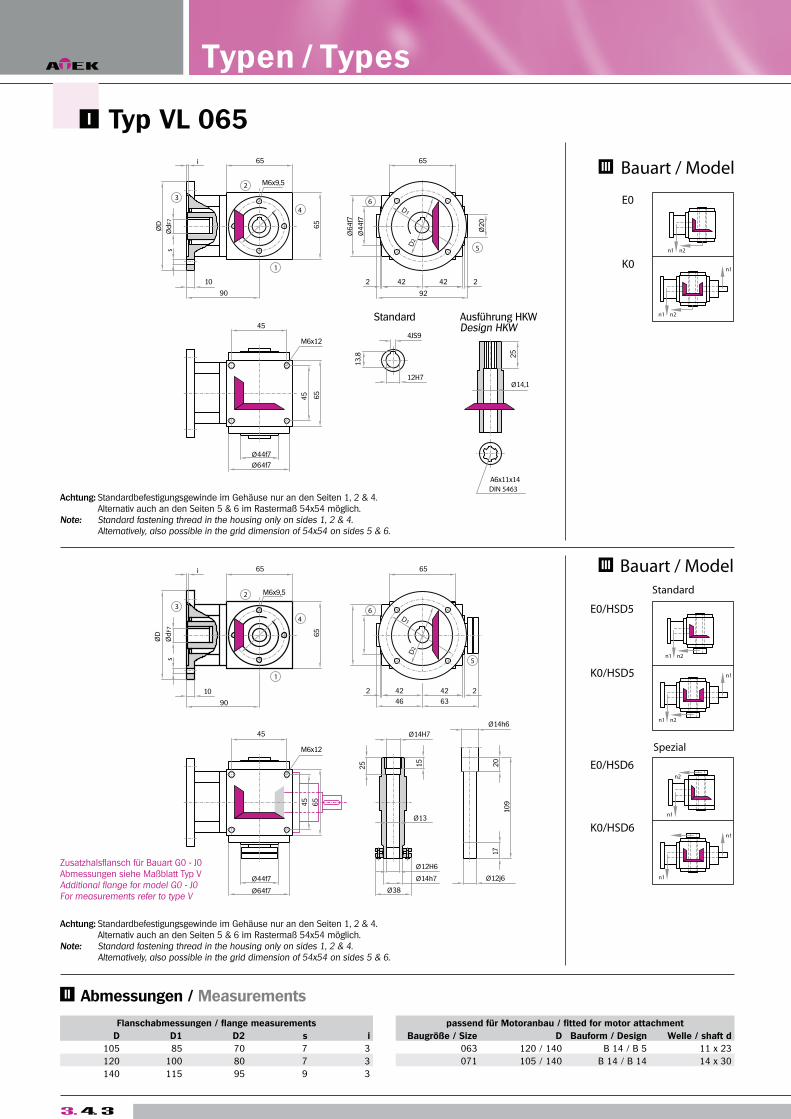
Flanschabmessungen / flange measurements passend für Motoranbau / fitted for motor attachment
D D1 D2 s i Baugröße / Size D Bauform / Design Welle / shaft d
105 85 70 7 3 063 120 / 140 B 14 / B 5 11 x 23
120 100 80 7 3 071 105 / 140 B 14 / B 14 14 x 30
140 115 95 9 3
Typen / Types
Abmessungen / Measurements
Zusatzhalsflansch für Bauart G0 - J0 Abmessungen siehe Maßblatt Typ VAdditional flange for model G0 - J0For measurements refer to type V
Typ VL 065
Achtung: Standardbefestigungsgewinde im Gehäuse nur an den Seiten 1, 2 & 4. Alternativ auch an den Seiten 5 & 6 im Rastermaß 54x54 möglich.Note: Standard fastening thread in the housing only on sides 1, 2 & 4. Alternatively, also possible in the grid dimension of 54x54 on sides 5 & 6.
Achtung: Standardbefestigungsgewinde im Gehäuse nur an den Seiten 1, 2 & 4. Alternativ auch an den Seiten 5 & 6 im Rastermaß 54x54 möglich.Note: Standard fastening thread in the housing only on sides 1, 2 & 4. Alternatively, also possible in the grid dimension of 54x54 on sides 5 & 6.
Kegelra
dgetrie
be T
yp V
B
eve
l Ge
arb
oxe
s T
yp
e V
T2 n2 (1/min) n2 (1/min)
Nm 3000 1000 500 250 100 50 3000 1000 500 250 100 50
< 12 180 250 300 350 450 550 300 400 500 650 750 900
> 12 150 210 250 290 380 460 250 330 420 540 630 750
3. 4. 4
Ø d x l 09x20 = -0,0013 11x23 = -0,0032 14x30 = -0,0107
i = 1:1 P1N 1,5:1 P1N 2:1 P1N 3:1 P1N
n1 n2 T2N n2 T2N n2 T2N n2 T2N
3000 3000 3,31 2000 2,20 1500 1,65 1000 1,10
10,00 10,00 10,00 10,00
2400 2400 2,65 1600 1,76 1200 1,32 800 0,88
10,00 10,00 10,00 10,00
1500 1500 1,82 1000 1,21 750 0,91 500 0,61
11,00 11,00 11,00 11,00
1000 1000 1,32 667 0,88 500 0,66 333 0,44
12,00 12,00 12,00 12,00
750 750 1,07 500 0,72 375 0,54 250 0,33
13,00 13,00 13,00 12,00
500 500 0,83 333 0,55 250 0,41 167 0,24
15,00 15,00 15,00 13,00
250 250 0,47 167 0,31 125 0,23 83 0,12
17,00 17,00 17,00 13,00
50 50 0,10 33 0,07 25 0,05 17 0,03
18,00 18,00 18,00 14,00
P1Nt 1,60 1,60 1,60 1,60
T2max 25,00 25,00 25,00 23,00
Bauart Übersetzung / Transmission Ratios
Model 1:1 1,5:1 2:1 3:1
E0 0,7072 0,6087 0,5377 0,4255
K0 0,9016 0,7629 0,6730 0,5075
E0/HSD 0,8330 0,7345 0,6635 0,5513
K0/HSD 1,0274 0,8887 0,7988 0,6333
Bauart ca. Gewicht
Model app. Weight
E0 3,1
K0 3,5
E0/HSD 3,1
K0/HSD 3,5
Abzug für Motorwellenbohrung / Reduction for motor shaft boret
Massenträgheitsmomente / Moments of Inertia J (kgcm2)reduziert auf die Antriebswelle (n1) / reduced to the input shaft (n1)
Getriebegewichte Gearbox Weights (kg)
Radialkräfte / Radial Forces (N)
Leistungen, Drehmomente / Power Ratings, Torque Ratings [n = min-1, P = kW, T = Nm]
Einbaulagen (unten liegende Getriebeseite) / Mounting Configuration (downward-facing side)
Befestigungsseite / Mounting Side
Weitere Erläuterungen und verstärkte Lagerungen siehe Allgemeines / For more information and reinforced bearings, refer to general Information.Axialkräfte FA = 50% der Radialkräfte - siehe Allgemeines / Axial forces FA = 50% of radial forces - refer to general information.
Bestellbeispiel / Example of Order
TypTypeVL
GrößeSize065
ÜbersetzungRatio
BauartModelE0
Befestigungss.Mounting Side
EinbaulageMounting Config.. 1
Drehzahl n2maxSpeed n2max
AusführungDesign0000=Standard
ø Flanschø FlangeD 120
Welle (ø x Länge) Shaft (ø x length)
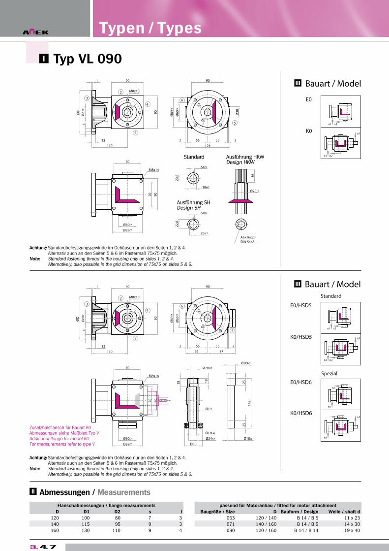
3. 4. 5
Flanschabmessungen / flange measurements passend für Motoranbau / fitted for motor attachment
D D1 D2 s i Baugröße / Size D Bauform / Design Welle / shaft d
120 100 80 7 3 063 120 / 140 B 14 / B 5 11 x 23
140 115 95 9 3 071 140 / 160 B 14 / B 5 14 x 30
160 130 110 9 4 080 120 / 160 B 14 / B 14 19 x 40
Typen / Types
Abmessungen / Measurements
Zusatzhalsflansch für Bauart G0 - J0 Abmessungen siehe Maßblatt Typ VAdditional flange for model G0 - J0For measurements refer to type V
Typ VL 090
Achtung: Standardbefestigungsgewinde im Gehäuse nur an den Seiten 1, 2 & 4. Alternativ auch an den Seiten 5 & 6 im Rastermaß 75x75 möglich.Note: Standard fastening thread in the housing only on sides 1, 2 & 4. Alternatively, also possible in the grid dimension of 75x75 on sides 5 & 6.
Achtung: Standardbefestigungsgewinde im Gehäuse nur an den Seiten 1, 2 & 4. Alternativ auch an den Seiten 5 & 6 im Rastermaß 75x75 möglich.Note: Standard fastening thread in the housing only on sides 1, 2 & 4. Alternatively, also possible in the grid dimension of 75x75 on sides 5 & 6.
Kegelra
dgetrie
be T
yp V
B
eve
l Ge
arb
oxe
s T
yp
e V
T2 n2 (1/min) n2 (1/min)
Nm 3000 1000 500 250 100 50 3000 1000 500 250 100 50
< 30 300 400 470 580 700 800 500 660 800 950 1250 1500
> 30 250 330 390 490 590 670 420 550 670 790 1040 1250
3. 4. 6
Ø d x l 11x23 = -0,0032 14x30 = -0,0107 19x40 = -0,0502
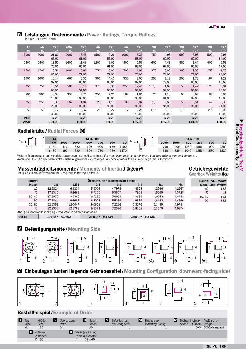
i = 1:1 P1N 1,5:1 P1N 2:1 P1N 3:1 P1N 4:1 P1N 5:1 P1N 6:1 P1N
n1 n2 T2N n2 T2N n2 T2N n2 T2N n2 T2N n2 T2N n2 T2N
3000 3000 8,93 2000 5,51 1500 3,80 1000 2,54 750 1,90 600 1,52 500 1,25
27,00 25,00 23,00 23,00 23,00 23,00 23,00
2400 2400 7,41 1600 4,59 1200 3,17 800 2,12 600 1,65 480 1,32 400 1,09
28,00 26,00 24,00 24,00 25,00 25,00 25,00
1500 1500 5,29 1000 3,20 750 2,23 500 1,49 375 1,12 300 0,89 250 0,74
32,00 29,00 27,00 27,00 27,00 27,00 27,00
1000 1000 3,75 667 2,35 500 1,71 333 1,14 250 0,85 200 0,68 167 0,53
34,00 32,00 31,00 31,00 31,00 31,00 29,00
750 750 3,06 500 1,93 375 1,32 250 0,88 187,5 0,66 150 0,53 125 0,40
37,00 35,00 32,00 32,00 32,00 32,00 29,00
500 500 2,20 333 1,36 250 0,94 167 0,63 125 0,47 100 0,37 83 0,27
40,00 37,00 34,00 34,00 34,00 34,00 29,00
250 250 1,21 167 0,74 125 0,50 83 0,33 62,5 0,25 50 0,20 42 0,14
44,00 40,00 36,00 36,00 36,00 36,00 30,00
50 50 0,28 33 0,15 25 0,10 17 0,07 12,5 0,05 10 0,04 8,3 0,03
50,00 40,00 37,00 37,00 37,00 37,00 33,00
P1Nt 3,80 3,80 3,80 3,80 3,80 3,80 3,80
T2max 105,00 40,00 80,00 70,00 70,00 60,00 50,00
Bauart Übersetzung / Transmission Ratios
Model 1:1 1,5:1 2:1 3:1 4:1 5:1 6:1
A0 2,8840 1,8274 1,4820 1,2212 1,1505 1,0992 1,0933
F0 4,1635 2,3960 1,8019 1,3633 1,2304 1,1504 1,1289
B0, C0 3,6793 2,5285 1,7035 1,3793 1,2481 1,1677 1,1373
D0 3,7077 2,5411 1,7106 1,3824 1,2499 1,1689 1,1381
G0, H0 4,9588 3,4420 2,5273 2,1255 1,5312 1,4413 1,4080
J0 4,9872 3,4546 2,5344 2,1286 1,5330 1,4425 1,4088
Bauart ca. Gewicht
Model app. Weight
A0 6,7
F0 7,9
B0, C0 7
D0 7,1
G0, H0 8,5
J0 8,6Abzug für Motorwellenbohrung / Reduction for motor shaft boret
Massenträgheitsmomente / Moments of Inertia J (kgcm2)reduziert auf die Antriebswelle (n1) / reduced to the input shaft (n1)
Getriebegewichte Gearbox Weights (kg)
Radialkräfte / Radial Forces (N)
Leistungen, Drehmomente / Power Ratings, Torque Ratings [n = min-1, P = kW, T = Nm]
Einbaulagen (unten liegende Getriebeseite) / Mounting Configuration (downward-facing side)
Befestigungsseite / Mounting Side
Weitere Erläuterungen und verstärkte Lagerungen siehe Allgemeines / For more information and reinforced bearings, refer to general Information.Axialkräfte FA = 50% der Radialkräfte - siehe Allgemeines / Axial forces FA = 50% of radial forces - refer to general information.
Bestellbeispiel / Example of Order
TypTypeVL
GrößeSize090
ÜbersetzungRatio
BauartModelA0
Befestigungss.Mounting Side
EinbaulageMounting Config.. 1
Drehzahl n2maxSpeed n2max
AusführungDesign0000=Standard
ø Flanschø FlangeD 140
Welle (ø x Länge) Shaft (ø x length)
3. 4. 7
Flanschabmessungen / flange measurements passend für Motoranbau / fitted for motor attachment
D D1 D2 s i Baugröße / Size D Bauform / Design Welle / shaft d
120 100 80 7 3 063 120 / 140 B 14 / B 5 11 x 23
140 115 95 9 3 071 140 / 160 B 14 / B 5 14 x 30
160 130 110 9 4 080 120 / 160 B 14 / B 14 19 x 40
Typen / Types
Abmessungen / Measurements
Zusatzhalsflansch für Bauart K0 Abmessungen siehe Maßblatt Typ VAdditional flange for model K0For measurements refer to type V
Typ VL 090
Achtung: Standardbefestigungsgewinde im Gehäuse nur an den Seiten 1, 2 & 4. Alternativ auch an den Seiten 5 & 6 im Rastermaß 75x75 möglich.Note: Standard fastening thread in the housing only on sides 1, 2 & 4. Alternatively, also possible in the grid dimension of 75x75 on sides 5 & 6.
Achtung: Standardbefestigungsgewinde im Gehäuse nur an den Seiten 1, 2 & 4. Alternativ auch an den Seiten 5 & 6 im Rastermaß 75x75 möglich.Note: Standard fastening thread in the housing only on sides 1, 2 & 4. Alternatively, also possible in the grid dimension of 75x75 on sides 5 & 6.
Kegelra
dgetrie
be T
yp V
B
eve
l Ge
arb
oxe
s T
yp
e V
3. 4. 8
Ø d x l 11x23 = -0,0032 14x30 = -0,0107 19x40 = -0,0502
i = 1:1 P1N 1,5:1 P1N 2:1 P1N 3:1 P1N 4:1 P1N 5:1 P1N 6:1 P1N
n1 n2 T2N n2 T2N n2 T2N n2 T2N n2 T2N n2 T2N n2 T2N
3000 3000 8,93 2000 5,51 1500 3,80 1000 2,54 750 1,90 600 1,52 500 1,25
27,00 25,00 23,00 23,00 23,00 23,00 23,00
2400 2400 7,41 1600 4,59 1200 3,17 800 2,12 600 1,65 480 1,32 400 1,09
28,00 26,00 24,00 24,00 25,00 25,00 25,00
1500 1500 5,29 1000 3,20 750 2,23 500 1,49 375 1,12 300 0,89 250 0,74
32,00 29,00 27,00 27,00 27,00 27,00 27,00
1000 1000 3,75 667 2,35 500 1,71 333 1,14 250 0,85 200 0,68 167 0,53
34,00 32,00 31,00 31,00 31,00 31,00 29,00
750 750 3,06 500 1,93 375 1,32 250 0,88 187,5 0,66 150 0,53 125 0,40
37,00 35,00 32,00 32,00 32,00 32,00 29,00
500 500 2,20 333 1,36 250 0,94 167 0,63 125 0,47 100 0,37 83 0,27
40,00 37,00 34,00 34,00 34,00 34,00 29,00
250 250 1,21 167 0,74 125 0,50 83 0,33 62,5 0,25 50 0,20 42 0,14
44,00 40,00 36,00 36,00 36,00 36,00 30,00
50 50 0,28 33 0,15 25 0,10 17 0,07 12,5 0,05 10 0,04 8,3 0,03
50,00 40,00 37,00 37,00 37,00 37,00 33,00
P1Nt 3,80 3,80 3,80 3,80 3,80 3,80 3,80
T2max 105,00 40,00 80,00 70,00 70,00 60,00 50,00
T2 n2 (1/min)
Nm 3000 1000 500 250 100 50
< 30 500 660 800 950 1250 1500
> 30 420 550 670 790 1040 1250
Bauart Übersetzung / Transmission Ratios
Model 1:1 1,5:1 2:1 3:1 4:1 5:1 6:1
E0 3,5757 2,4824 1,6776 1,3678 1,2416 1,1636 1,1344
K0 4,8552 3,3959 2,5014 2,1140 1,5247 1,4372 1,4051
E0/HSD 4,2463 2,7805 1,8452 1,4423 1,2835 1,1904 1,1531
K0/HSD 5,5258 3,6940 2,6690 2,1885 1,5666 1,4611 1,4238
Bauart ca. Gewicht
Model app. Weight
E0 6,6
K0 8,1
E0/HSD 6,8
K0/HSD 8,3
Abzug für Motorwellenbohrung / Reduction for motor shaft boret
Massenträgheitsmomente / Moments of Inertia J (kgcm2)reduziert auf die Antriebswelle (n1) / reduced to the input shaft (n1)
Getriebegewichte Gearbox Weights (kg)
Radialkräfte / Radial Forces (N)
Leistungen, Drehmomente / Power Ratings, Torque Ratings [n = min-1, P = kW, T = Nm]
Einbaulagen (unten liegende Getriebeseite) / Mounting Configuration (downward-facing side)
Befestigungsseite / Mounting Side
Weitere Erläuterungen und verstärkte Lagerungen siehe Allgemeines / For more information and reinforced bearings, refer to general Information.Axialkräfte FA = 50% der Radialkräfte - siehe Allgemeines / Axial forces FA = 50% of radial forces - refer to general information.
Bestellbeispiel / Example of Order
TypTypeVL
GrößeSize090
ÜbersetzungRatio
BauartModelE0
Befestigungss.Mounting Side
EinbaulageMounting Config.. 1
Drehzahl n2maxSpeed n2max
AusführungDesign0000=Standard
ø Flanschø FlangeD 140
Welle (ø x Länge) Shaft (ø x length)
3. 4. 9
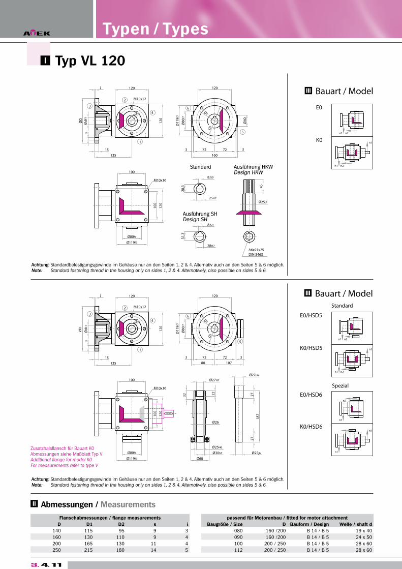
Flanschabmessungen / flange measurements passend für Motoranbau / fitted for motor attachment
D D1 D2 s i Baugröße / Size D Bauform / Design Welle / shaft d
140 115 95 9 3 080 160 /200 B 14 / B 5 19 x 40
160 130 110 9 4 090 160 /200 B 14 / B 5 24 x 50
200 165 130 11 4 100 200 / 250 B 14 / B 5 28 x 60
250 215 180 14 5 112 200 / 250 B 14 / B 5 28 x 60
Typen / Types
Achtung: Standardbefestigungsgewinde im Gehäuse nur an den Seiten 1, 2 & 4. Alternativ auch an den Seiten 5 & 6 möglich.Note: Standard fastening thread in the housing only on sides 1, 2 & 4. Alternatively, also possible on sides 5 & 6.
Achtung: Standardbefestigungsgewinde im Gehäuse nur an den Seiten 1, 2 & 4. Alternativ auch an den Seiten 5 & 6 möglich.Note: Standard fastening thread in the housing only on sides 1, 2 & 4. Alternatively, also possible on sides 5 & 6.
Abmessungen / Measurements
Zusatzhalsflansch für Bauart G0 - J0 Abmessungen siehe Maßblatt Typ VAdditional flange for model G0 - J0For measurements refer to type V
Typ VL 120
Kegelra
dgetrie
be T
yp V
B
eve
l Ge
arb
oxe
s T
yp
e V
T2 n2 (1/min) n2 (1/min)
Nm 3000 1000 500 250 100 50 3000 1000 500 250 100 50
< 80 470 620 720 900 1150 1400 750 1000 1250 1500 1900 2200
> 80 390 520 600 750 960 1170 630 830 1040 1250 1580 1830
3. 4. 10
Ø d x l 19x40 = -0,0502 24x50 = -0,1534 28x60 = -0,3126
i = 1:1 P1N 1,5:1 P1N 2:1 P1N 3:1 P1N 4:1 P1N 5:1 P1N 6:1 P1N
n1 n2 T2N n2 T2N n2 T2N n2 T2N n2 T2N n2 T2N n2 T2N
3000 3000 21,82 2000 13,45 1500 9,26 1000 6,39 750 4,96 600 3,97 500 2,95
66,00 61,00 56,00 58,00 60,00 60,00 54,00
2400 2400 18,52 1600 11,46 1200 8,07 800 5,56 600 4,43 480 3,44 400 2,53
70,00 65,00 61,00 63,00 67,00 65,00 57,00
1500 1500 13,56 1000 8,60 750 6,03 500 4,08 375 3,06 300 2,38 250 1,75
82,00 78,00 73,00 74,00 74,00 72,00 64,00
1000 1000 10,14 667 6,32 500 4,40 333 3,01 250 2,18 200 1,76 167 1,22
92,00 86,00 80,00 82,00 79,00 80,00 66,00
750 750 8,51 500 5,18 375 3,30 250 2,40 187,5 1,69 150 1,42 125 0,94
103,00 94,00 80,00 87,00 82,00 86,00 68,00
500 500 6,34 333 3,70 250 2,20 167 1,66 125 1,16 100 0,98 83 0,63
115,00 100,00 80,00 90,00 84,00 89,00 69,00
250 250 3,39 167 1,84 125 1,10 83 0,87 62,5 0,60 50 0,51 42 0,33
123,00 100,00 80,00 95,00 87,00 92,00 71,00
50 50 0,72 33 0,37 25 0,22 17 0,21 12,5 0,12 10 0,10 8,3 0,06
130,00 100,00 80,00 110,00 90,00 95,00 66,00
P1Nt 6,20 6,20 6,20 6,20 6,20 6,20 6,20
T2max 220,00 100,00 80,00 155,00 155,00 140,00 120,00
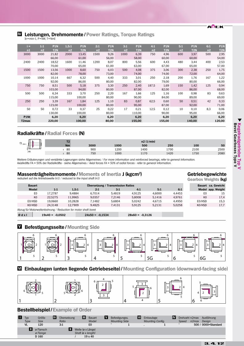
Bauart Übersetzung / Transmission Ratios
Model 1:1 1,5:1 2:1 3:1 4:1 5:1 6:1
A0 12,5824 6,9334 5,4003 4,7975 4,4628 4,2966 4,2267
F0 17,8312 9,2662 6,7125 5,3807 4,7908 4,5065 4,3725
B0, C0 17,3870 9,5366 6,7285 5,4939 4,9193 4,6043 4,4483
D0 17,6844 9,6687 6,8028 5,5269 4,9379 4,6162 4,4566
G0, H0 22,6358 12,0447 9,0628 7,2266 5,8076 5,1459 4,9791
J0 22,9332 12,1768 9,1371 7,2596 5,8262 5,1578 4,9874
Bauart ca. Gewicht
Model app. Weight
A0 15,6
F0 18
B0, C0 15,3
D0 15,5
Abzug für Motorwellenbohrung / Reduction for motor shaft boret
Massenträgheitsmomente / Moments of Inertia J (kgcm2)reduziert auf die Antriebswelle (n1) / reduced to the input shaft (n1)
Getriebegewichte Gearbox Weights (kg)
Radialkräfte / Radial Forces (N)
Leistungen, Drehmomente / Power Ratings, Torque Ratings [n = min-1, P = kW, T = Nm]
Einbaulagen (unten liegende Getriebeseite) / Mounting Configuration (downward-facing side)
Befestigungsseite / Mounting Side
Weitere Erläuterungen und verstärkte Lagerungen siehe Allgemeines / For more information and reinforced bearings, refer to general Information.Axialkräfte FA = 50% der Radialkräfte - siehe Allgemeines / Axial forces FA = 50% of radial forces - refer to general information.
Bestellbeispiel / Example of Order
TypTypeVL
GrößeSize120
ÜbersetzungRatio
BauartModelA0
Befestigungss.Mounting Side
EinbaulageMounting Config.. 1
Drehzahl n2maxSpeed n2max
AusführungDesign0000=Standard
ø Flanschø FlangeD 160
Welle (ø x Länge) Shaft (ø x length)/ 19 x 40
3. 4. 11
Flanschabmessungen / flange measurements passend für Motoranbau / fitted for motor attachment
D D1 D2 s i Baugröße / Size D Bauform / Design Welle / shaft d
140 115 95 9 3 080 160 /200 B 14 / B 5 19 x 40
160 130 110 9 4 090 160 /200 B 14 / B 5 24 x 50
200 165 130 11 4 100 200 / 250 B 14 / B 5 28 x 60
250 215 180 14 5 112 200 / 250 B 14 / B 5 28 x 60
Typen / Types
Achtung: Standardbefestigungsgewinde im Gehäuse nur an den Seiten 1, 2 & 4. Alternativ auch an den Seiten 5 & 6 möglich.Note: Standard fastening thread in the housing only on sides 1, 2 & 4. Alternatively, also possible on sides 5 & 6.
Achtung: Standardbefestigungsgewinde im Gehäuse nur an den Seiten 1, 2 & 4. Alternativ auch an den Seiten 5 & 6 möglich.Note: Standard fastening thread in the housing only on sides 1, 2 & 4. Alternatively, also possible on sides 5 & 6.
Abmessungen / Measurements
Zusatzhalsflansch für Bauart K0 Abmessungen siehe Maßblatt Typ VAdditional flange for model K0For measurements refer to type V
Typ VL 120
Kegelra
dgetrie
be T
yp V
B
eve
l Ge
arb
oxe
s T
yp
e V
3. 4. 12
Ø d x l 19x40 = -0,0502 24x50 = -0,1534 28x60 = -0,3126
i = 1:1 P1N 1,5:1 P1N 2:1 P1N 3:1 P1N 4:1 P1N 5:1 P1N 6:1 P1N
n1 n2 T2N n2 T2N n2 T2N n2 T2N n2 T2N n2 T2N n2 T2N
3000 3000 21,82 2000 13,45 1500 9,26 1000 6,39 750 4,96 600 3,97 500 2,95
66,00 61,00 56,00 58,00 60,00 60,00 54,00
2400 2400 18,52 1600 11,46 1200 8,07 800 5,56 600 4,43 480 3,44 400 2,53
70,00 65,00 61,00 63,00 67,00 65,00 57,00
1500 1500 13,56 1000 8,60 750 6,03 500 4,08 375 3,06 300 2,38 250 1,75
82,00 78,00 73,00 74,00 74,00 72,00 64,00
1000 1000 10,14 667 6,32 500 4,40 333 3,01 250 2,18 200 1,76 167 1,22
92,00 86,00 80,00 82,00 79,00 80,00 66,00
750 750 8,51 500 5,18 375 3,30 250 2,40 187,5 1,69 150 1,42 125 0,94
103,00 94,00 80,00 87,00 82,00 86,00 68,00
500 500 6,34 333 3,70 250 2,20 167 1,66 125 1,16 100 0,98 83 0,63
115,00 100,00 80,00 90,00 84,00 89,00 69,00
250 250 3,39 167 1,84 125 1,10 83 0,87 62,5 0,60 50 0,51 42 0,33
123,00 100,00 80,00 95,00 87,00 92,00 71,00
50 50 0,72 33 0,37 25 0,22 17 0,21 12,5 0,12 10 0,10 8,3 0,06
130,00 100,00 80,00 110,00 90,00 95,00 66,00
P1Nt 6,20 6,20 6,20 6,20 6,20 6,20 6,20
T2max 220,00 100,00 80,00 155,00 155,00 140,00 120,00
T2 n2 (1/min)
Nm 3000 1000 500 250 100 50
< 80 900 1200 1400 1700 2100 2500
> 80 750 1000 1170 1420 1750 2080
Bauart Übersetzung / Transmission Ratios
Model 1:1 1,5:1 2:1 3:1 4:1 5:1 6:1
E0 17,2787 9,4884 6,7014 5,4819 4,9125 4,6000 4,4453
K0 22,5275 11,9965 9,0357 7,2146 5,8008 5,1416 4,9761
E0/HSD 19,0660 10,2828 7,1482 5,6804 5,0242 4,6715 4,4950
K0/HSD 24,3148 12,7909 9,4825 7,4131 5,9125 5,2131 5,0258
Bauart ca. Gewicht
Model app. Weight
E0 15
K0 17,4
E0/HSD 15,3
K0/HSD 17,7
Abzug für Motorwellenbohrung / Reduction for motor shaft boret
Massenträgheitsmomente / Moments of Inertia J (kgcm2)reduziert auf die Antriebswelle (n1) / reduced to the input shaft (n1)
Getriebegewichte Gearbox Weights (kg)
Radialkräfte / Radial Forces (N)
Leistungen, Drehmomente / Power Ratings, Torque Ratings [n = min-1, P = kW, T = Nm]
Einbaulagen (unten liegende Getriebeseite) / Mounting Configuration (downward-facing side)
Befestigungsseite / Mounting Side
Weitere Erläuterungen und verstärkte Lagerungen siehe Allgemeines / For more information and reinforced bearings, refer to general Information.Axialkräfte FA = 50% der Radialkräfte - siehe Allgemeines / Axial forces FA = 50% of radial forces - refer to general information.
Bestellbeispiel / Example of Order
TypTypeVL
GrößeSize120
ÜbersetzungRatio
BauartModelE0
Befestigungss.Mounting Side
EinbaulageMounting Config.. 1
Drehzahl n2maxSpeed n2max
AusführungDesign0000=Standard
ø Flanschø FlangeD 160
Welle (ø x Länge) Shaft (ø x length)/ 19 x 40
3. 4. 13
*Übersetzung 3:1 - 6:1 mit Zwischenflansch oder gekürzter MotorwelleRatio 3:1 - 6:1 with flange or shortened motor shaft
Flanschabmessungen / flange measurements passend für Motoranbau / fitted for motor attachment
D D1 D2 s i Baugröße / Size D Bauform / Design Welle / shaft d
160 130 110 9 4 090 160 /200 B 14 / B 5 24 x 50
200 165 130 11 4 100 / 112 200 / 250 B 14 / B 5 28 x 60
250 215 180 14 5 132 200 / 250 B 14 / B 5 38 x 60/80*
Typen / Types
Achtung: Standardbefestigungsgewinde im Gehäuse nur an den Seiten 1, 2 & 4. Alternativ auch an den Seiten 5 & 6 möglich.Note: Standard fastening thread in the housing only on sides 1, 2 & 4. Alternatively, also possible on sides 5 & 6.
Achtung: Standardbefestigungsgewinde im Gehäuse nur an den Seiten 1, 2 & 4. Alternativ auch an den Seiten 5 & 6 möglich.Note: Standard fastening thread in the housing only on sides 1, 2 & 4. Alternatively, also possible on sides 5 & 6.
Abmessungen / Measurements
Zusatzhalsflansch für Bauart G0 - J0 Abmessungen siehe Maßblatt Typ VAdditional flange for model G0 - J0For measurements refer to type V
Typ VL 140

Kegelra
dgetrie
be T
yp V
B
eve
l Ge
arb
oxe
s T
yp
e V
T2 n2 (1/min) n2 (1/min)
Nm 3000 1000 500 250 100 50 3000 1000 500 250 100 50
< 140 700 870 1150 1370 1700 2000 1300 1700 2000 2500 3000 3800
> 140 590 730 960 1140 1420 1670 1083 1420 1670 2080 2500 3170
3. 4. 14
Ø d x l 24x50 = -0,1534 28x60 = -0,3126 32x60 = -0,5253 38x60 = -1,0445 38x80 = -1,3659
i = 1:1 P1N 1,5:1 P1N 2:1 P1N 3:1 P1N 4:1 P1N 5:1 P1N 6:1 P1N
n1 n2 T2N n2 T2N n2 T2N n2 T2N n2 T2N n2 T2N n2 T2N
3000 3000 39,68 2000 24,91 1500 16,53 1000 12,12 750 8,51 600 6,61 500 5,18
120,00 113,00 100,00 110,00 103,00 100,00 94,00
2400 2400 37,04 1600 22,22 1200 14,68 800 11,46 600 7,34 480 5,56 400 4,58
140,00 126,00 111,00 130,00 111,00 105,00 104,00
1500 1500 26,78 1000 17,08 750 11,41 500 8,05 375 4,96 300 3,80 250 2,95
162,00 155,00 138,00 146,00 120,00 115,00 107,00
1000 1000 20,28 667 12,87 500 8,38 333 5,87 250 3,75 200 2,73 167 2,06
184,00 175,00 152,00 160,00 136,00 124,00 112,00
750 750 16,20 500 10,47 375 6,86 250 4,60 187,5 3,06 150 2,15 125 1,61
196,00 190,00 166,00 167,00 148,00 130,00 117,00
500 500 11,46 333 7,34 250 4,96 167 3,20 125 2,12 100 1,50 83 1,09
208,00 200,00 180,00 174,00 154,00 136,00 119,00
250 250 5,92 167 3,76 125 2,48 83 1,62 62,5 1,12 50 0,79 42 0,56
215,00 204,00 180,00 177,00 162,00 143,00 121,00
50 50 1,21 33 0,76 25 0,50 17 0,34 12,5 0,23 10 0,17 8,3 0,11
220,00 210,00 180,00 180,00 170,00 150,00 120,00
P1Nt 10,00 10,00 10,00 10,00 10,00 10,00 10,00
T2max 430,00 210,00 180,00 280,00 280,00 250,00 200,00
Bauart Übersetzung / Transmission Ratios
Model 1:1 1,5:1 2:1 3:1 4:1 5:1 6:1
A0 12,5824 6,9334 5,4003 4,7975 4,4628 4,2966 4,2267
F0 17,8312 9,2662 6,7125 5,3807 4,7908 4,5065 4,3725
B0, C0 17,3870 9,5366 6,7285 5,4939 4,9193 4,6043 4,4483
D0 17,6844 9,6687 6,8028 5,5269 4,9379 4,6162 4,4566
G0, H0 22,6358 12,0447 9,0628 7,2266 5,8076 5,1459 4,9791
J0 22,9332 12,1768 9,1371 7,2596 5,8262 5,1578 4,9874
Bauart ca. Gewicht
Model app. Weight
A0 24
F0 28
B0, C0 23,5
D0 24
G0, H0 27,7
J0 28,2
Abzug für Motorwellenbohrung / Reduction for motor shaft boret
Massenträgheitsmomente / Moments of Inertia J (kgcm2)reduziert auf die Antriebswelle (n1) / reduced to the input shaft (n1)
Getriebegewichte Gearbox Weights (kg)
Radialkräfte / Radial Forces (N)
Leistungen, Drehmomente / Power Ratings, Torque Ratings [n = min-1, P = kW, T = Nm]
Einbaulagen (unten liegende Getriebeseite) / Mounting Configuration (downward-facing side)
Befestigungsseite / Mounting Side
Weitere Erläuterungen und verstärkte Lagerungen siehe Allgemeines / For more information and reinforced bearings, refer to general Information.Axialkräfte FA = 50% der Radialkräfte - siehe Allgemeines / Axial forces FA = 50% of radial forces - refer to general information.
Bestellbeispiel / Example of Order
TypTypeVL
GrößeSize140
ÜbersetzungRatio
BauartModelA0
Befestigungss.Mounting Side
EinbaulageMounting Config.. 1
Drehzahl n2maxSpeed n2max
AusführungDesign0000=Standard
ø Flanschø FlangeD 200
Welle (ø x Länge) Shaft (ø x length)/ 28 x 60
3. 4. 15
Flanschabmessungen / flange measurements passend für Motoranbau / fitted for motor attachment
D D1 D2 s i Baugröße / Size D Bauform / Design Welle / shaft d
160 130 110 9 4 090 160 /200 B 14 / B 5 24 x 50
200 165 130 11 4 100 / 112 200 / 250 B 14 / B 5 28 x 60
250 215 180 14 5 132 200 / 250 B 14 / B 5 38 x 60/80*
Typen / Types
*Übersetzung 3:1 - 6:1 mit Zwischenflansch oder gekürzter MotorwelleRatio 3:1 - 6:1 with flange or shortened motor shaft
Achtung: Standardbefestigungsgewinde im Gehäuse nur an den Seiten 1, 2 & 4. Alternativ auch an den Seiten 5 & 6 möglich.Note: Standard fastening thread in the housing only on sides 1, 2 & 4. Alternatively, also possible on sides 5 & 6.
Achtung: Standardbefestigungsgewinde im Gehäuse nur an den Seiten 1, 2 & 4. Alternativ auch an den Seiten 5 & 6 möglich.Note: Standard fastening thread in the housing only on sides 1, 2 & 4. Alternatively, also possible on sides 5 & 6.
Abmessungen / Measurements
Zusatzhalsflansch für Bauart K0 Abmessungen siehe Maßblatt Typ VAdditional flange for model K0For measurements refer to type V
Typ VL 140
Kegelra
dgetrie
be T
yp V
B
eve
l Ge
arb
oxe
s T
yp
e V
3. 4. 16
Ø d x l 24x50 = -0,1534 28x60 = -0,3126 32x60 = -0,5253 38x60 = -1,0445 38x80 = -1,3659
i = 1:1 P1N 1,5:1 P1N 2:1 P1N 3:1 P1N 4:1 P1N 5:1 P1N 6:1 P1N
n1 n2 T2N n2 T2N n2 T2N n2 T2N n2 T2N n2 T2N n2 T2N
3000 3000 39,68 2000 24,91 1500 16,53 1000 12,12 750 8,51 600 6,61 500 5,18
120,00 113,00 100,00 110,00 103,00 100,00 94,00
2400 2400 37,04 1600 22,22 1200 14,68 800 11,46 600 7,34 480 5,56 400 4,58
140,00 126,00 111,00 130,00 111,00 105,00 104,00
1500 1500 26,78 1000 17,08 750 11,41 500 8,05 375 4,96 300 3,80 250 2,95
162,00 155,00 138,00 146,00 120,00 115,00 107,00
1000 1000 20,28 667 12,87 500 8,38 333 5,87 250 3,75 200 2,73 167 2,06
184,00 175,00 152,00 160,00 136,00 124,00 112,00
750 750 16,20 500 10,47 375 6,86 250 4,60 187,5 3,06 150 2,15 125 1,61
196,00 190,00 166,00 167,00 148,00 130,00 117,00
500 500 11,46 333 7,34 250 4,96 167 3,20 125 2,12 100 1,50 83 1,09
208,00 200,00 180,00 174,00 154,00 136,00 119,00
250 250 5,92 167 3,76 125 2,48 83 1,62 62,5 1,12 50 0,79 42 0,56
215,00 204,00 180,00 177,00 162,00 143,00 121,00
50 50 1,21 33 0,76 25 0,50 17 0,34 12,5 0,23 10 0,17 8,3 0,11
220,00 210,00 180,00 180,00 170,00 150,00 120,00
P1Nt 10,00 10,00 10,00 10,00 10,00 10,00 10,00
T2max 430,00 210,00 180,00 280,00 280,00 250,00 200,00
T2 n2 (1/min)
Nm 3000 1000 500 250 100 50
< 140 1300 1700 2000 2500 3000 3800
> 140 1083 1420 1670 2080 2500 3170
Bauart Übersetzung / Transmission Ratios
Model 1:1 1,5:1 2:1 3:1 4:1 5:1 6:1
E0 42,4047 26,7092 20,7879 17,1127 15,5697 15,1763 14,8502
K0 55,5382 32,7290 26,1807 22,0890 16,5921 16,1830 15,8562
E0/HSD 48,8060 29,5543 22,3883 17,8240 15,9698 15,4323 15,0280
K0/HSD 61,9395 35,5741 27,7811 22,8003 16,9922 16,4390 16,0340
Bauart ca. Gewicht
Model app. Weight
E0 23
K0 27,2
E0/HSD 23,7
K0/HSD 27,9
Abzug für Motorwellenbohrung / Reduction for motor shaft boret
Massenträgheitsmomente / Moments of Inertia J (kgcm2)reduziert auf die Antriebswelle (n1) / reduced to the input shaft (n1)
Getriebegewichte Gearbox Weights (kg)
Radialkräfte / Radial Forces (N)
Leistungen, Drehmomente / Power Ratings, Torque Ratings [n = min-1, P = kW, T = Nm]
Einbaulagen (unten liegende Getriebeseite) / Mounting Configuration (downward-facing side)
Befestigungsseite / Mounting Side
Weitere Erläuterungen und verstärkte Lagerungen siehe Allgemeines / For more information and reinforced bearings, refer to general Information.Axialkräfte FA = 50% der Radialkräfte - siehe Allgemeines / Axial forces FA = 50% of radial forces - refer to general information.
Bestellbeispiel / Example of Order
TypTypeVL
GrößeSize140
ÜbersetzungRatio
BauartModelE0
Befestigungss.Mounting Side
EinbaulageMounting Config.. 1
Drehzahl n2maxSpeed n2max
AusführungDesign0000=Standard
ø Flanschø FlangeD 200
Welle (ø x Länge) Shaft (ø x length)/ 28 x 60
3. 4. 17
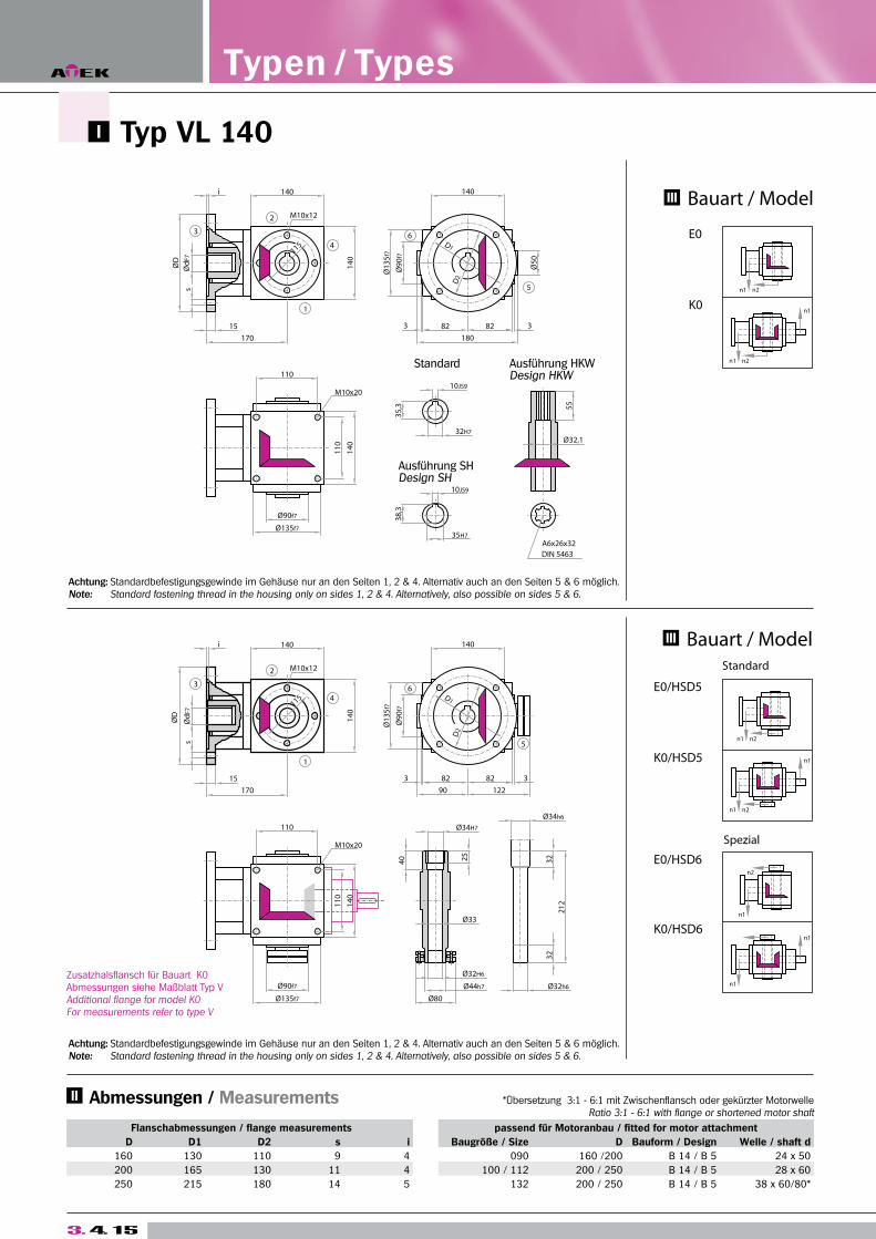
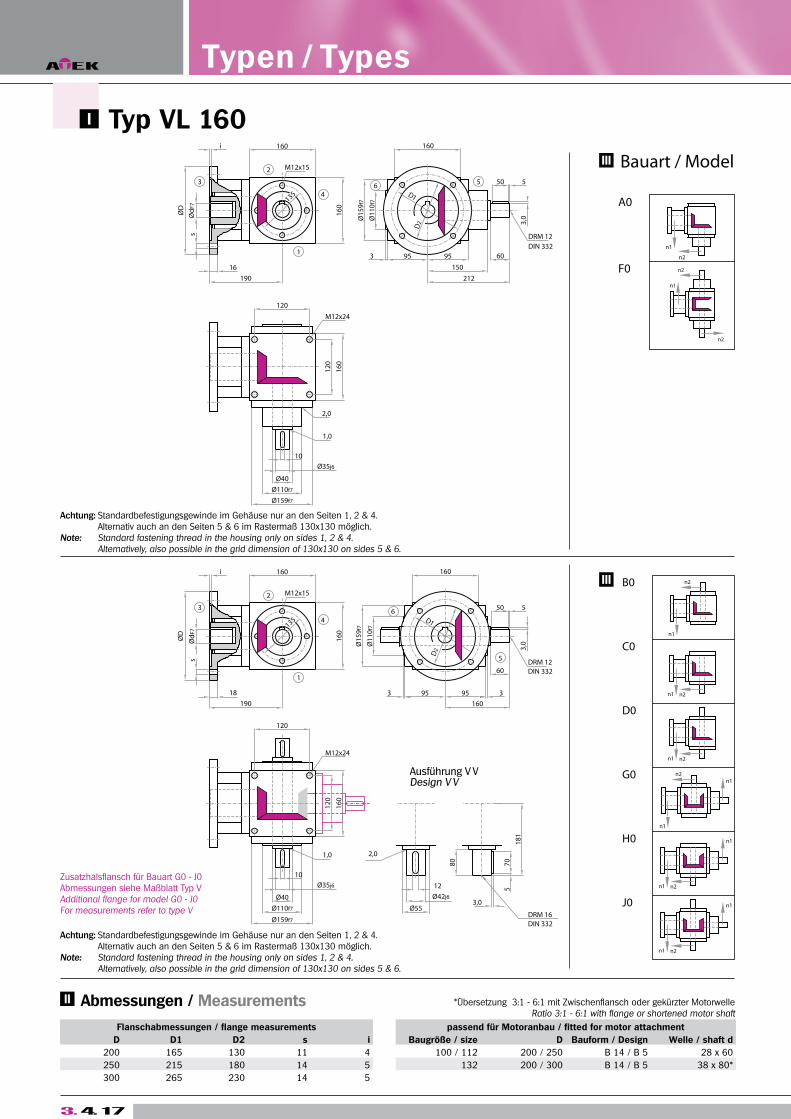
Flanschabmessungen / flange measurements passend für Motoranbau / fitted for motor attachment
D D1 D2 s i Baugröße / size D Bauform / Design Welle / shaft d
200 165 130 11 4 100 / 112 200 / 250 B 14 / B 5 28 x 60
250 215 180 14 5 132 200 / 300 B 14 / B 5 38 x 80*
300 265 230 14 5
Typen / Types
Zusatzhalsflansch für Bauart G0 - J0 Abmessungen siehe Maßblatt Typ VAdditional flange for model G0 - J0For measurements refer to type V
Typ VL 160
Achtung: Standardbefestigungsgewinde im Gehäuse nur an den Seiten 1, 2 & 4. Alternativ auch an den Seiten 5 & 6 im Rastermaß 130x130 möglich.Note: Standard fastening thread in the housing only on sides 1, 2 & 4. Alternatively, also possible in the grid dimension of 130x130 on sides 5 & 6.
Achtung: Standardbefestigungsgewinde im Gehäuse nur an den Seiten 1, 2 & 4. Alternativ auch an den Seiten 5 & 6 im Rastermaß 130x130 möglich.Note: Standard fastening thread in the housing only on sides 1, 2 & 4. Alternatively, also possible in the grid dimension of 130x130 on sides 5 & 6.
*Übersetzung 3:1 - 6:1 mit Zwischenflansch oder gekürzter MotorwelleRatio 3:1 - 6:1 with flange or shortened motor shaft
Abmessungen / Measurements
Kegelra
dgetrie
be T
yp V
B
eve
l Ge
arb
oxe
s T
yp
e V
T2 n2 (1/min) n2 (1/min)
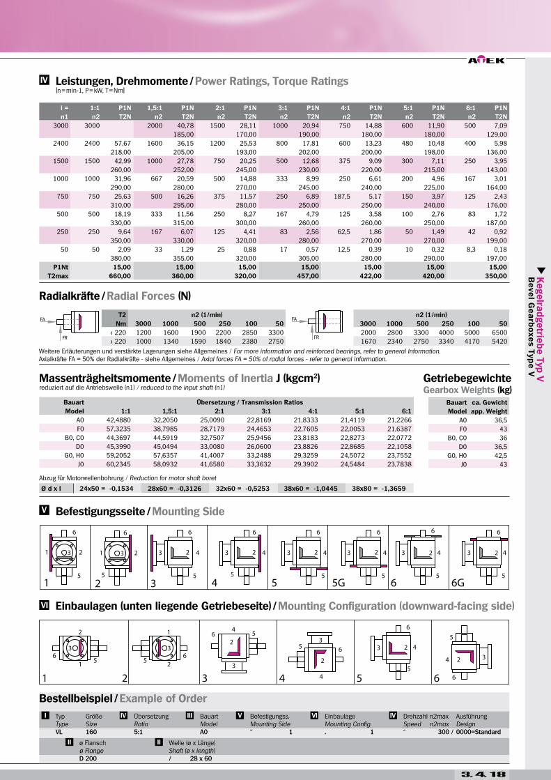
Nm 3000 1000 500 250 100 50 3000 1000 500 250 100 50
< 220 1200 1600 1900 2200 2850 3300 2000 2800 3300 4000 5000 6500
> 220 1000 1340 1590 1840 2380 2750 1670 2340 2750 3340 4170 5420
3. 4. 18
Ø d x l 24x50 = -0,1534 28x60 = -0,3126 32x60 = -0,5253 38x60 = -1,0445 38x80 = -1,3659
i = 1:1 P1N 1,5:1 P1N 2:1 P1N 3:1 P1N 4:1 P1N 5:1 P1N 6:1 P1N
n1 n2 T2N n2 T2N n2 T2N n2 T2N n2 T2N n2 T2N n2 T2N
3000 3000 2000 40,78 1500 28,11 1000 20,94 750 14,88 600 11,90 500 7,09
185,00 170,00 190,00 180,00 180,00 129,00
2400 2400 57,67 1600 36,15 1200 25,53 800 17,81 600 13,23 480 10,48 400 5,98
218,00 205,00 193,00 202,00 200,00 198,00 136,00
1500 1500 42,99 1000 27,78 750 20,25 500 12,68 375 9,09 300 7,11 250 3,95
260,00 252,00 245,00 230,00 220,00 215,00 143,00
1000 1000 31,96 667 20,59 500 14,88 333 8,99 250 6,61 200 4,96 167 3,01
290,00 280,00 270,00 245,00 240,00 225,00 164,00
750 750 25,63 500 16,26 375 11,57 250 6,89 187,5 5,17 150 3,97 125 2,43
310,00 295,00 280,00 250,00 250,00 240,00 176,00
500 500 18,19 333 11,56 250 8,27 167 4,79 125 3,58 100 2,76 83 1,72
330,00 315,00 300,00 260,00 260,00 250,00 187,00
250 250 9,64 167 6,07 125 4,41 83 2,56 62,5 1,86 50 1,49 42 0,92
350,00 330,00 320,00 280,00 270,00 270,00 199,00
50 50 2,09 33 1,29 25 0,88 17 0,57 12,5 0,39 10 0,32 8,3 0,18
380,00 355,00 320,00 305,00 280,00 290,00 197,00
P1Nt 15,00 15,00 15,00 15,00 15,00 15,00 15,00
T2max 660,00 360,00 320,00 457,00 422,00 420,00 350,00
Bauart Übersetzung / Transmission Ratios
Model 1:1 1,5:1 2:1 3:1 4:1 5:1 6:1
A0 42,4880 32,2050 25,0090 22,8169 21,8333 21,4119 21,2266
F0 57,3235 38,7985 28,7179 24,4653 22,7605 22,0053 21,6387
B0, C0 44,3697 44,5919 32,7507 25,9456 23,8183 22,8273 22,0772
D0 45,3990 45,0494 33,0080 26,0600 23,8826 22,8685 22,1058
G0, H0 59,2052 57,6357 41,4007 33,2488 29,3259 24,5072 23,7552
J0 60,2345 58,0932 41,6580 33,3632 29,3902 24,5484 23,7838
Bauart ca. Gewicht
Model app. Weight
A0 36,5
F0 43
B0, C0 36
D0 36,5
G0, H0 42,5
J0 43
Abzug für Motorwellenbohrung / Reduction for motor shaft boret
Massenträgheitsmomente / Moments of Inertia J (kgcm2)reduziert auf die Antriebswelle (n1) / reduced to the input shaft (n1)
Getriebegewichte Gearbox Weights (kg)
Radialkräfte / Radial Forces (N)
Leistungen, Drehmomente / Power Ratings, Torque Ratings [n = min-1, P = kW, T = Nm]
Einbaulagen (unten liegende Getriebeseite) / Mounting Configuration (downward-facing side)
Befestigungsseite / Mounting Side
Weitere Erläuterungen und verstärkte Lagerungen siehe Allgemeines / For more information and reinforced bearings, refer to general Information.Axialkräfte FA = 50% der Radialkräfte - siehe Allgemeines / Axial forces FA = 50% of radial forces - refer to general information.
Bestellbeispiel / Example of Order
TypTypeVL
GrößeSize160
ÜbersetzungRatio5:1
BauartModelA0
Befestigungss.Mounting Side
EinbaulageMounting Config.. 1
Drehzahl n2maxSpeed n2max
AusführungDesign0000=Standard
ø Flanschø FlangeD 200
Welle (ø x Länge) Shaft (ø x length)/ 28 x 60
3. 4. 19
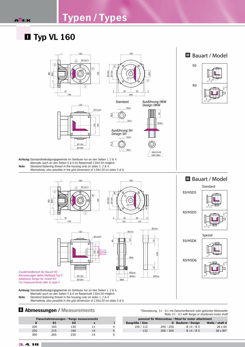
Zusatzhalsflansch für Bauart K0Abmessungen siehe Maßblatt Typ VAdditional flange for model K0For measurements refer to type V
Typ VL 160
Achtung: Standardbefestigungsgewinde im Gehäuse nur an den Seiten 1, 2 & 4. Alternativ auch an den Seiten 5 & 6 im Rastermaß 130x130 möglich.Note: Standard fastening thread in the housing only on sides 1, 2 & 4. Alternatively, also possible in the grid dimension of 130x130 on sides 5 & 6.
Achtung: Standardbefestigungsgewinde im Gehäuse nur an den Seiten 1, 2 & 4. Alternativ auch an den Seiten 5 & 6 im Rastermaß 130x130 möglich.Note: Standard fastening thread in the housing only on sides 1, 2 & 4. Alternatively, also possible in the grid dimension of 130x130 on sides 5 & 6.
Flanschabmessungen / flange measurements passend für Motoranbau / fitted for motor attachment
D D1 D2 s i Baugröße / Size D Bauform / Design Welle / shaft d
200 165 130 11 4 100 / 112 200 / 250 B 14 / B 5 28 x 60
250 215 180 14 5 132 200 / 300 B 14 / B 5 38 x 80*
300 265 230 14 5
Typen / Types
*Übersetzung 3:1 - 6:1 mit Zwischenflansch oder gekürzter MotorwelleRatio 3:1 - 6:1 with flange or shortened motor shaft
Abmessungen / Measurements
Kegelra
dgetrie
be T
yp V
B
eve
l Ge
arb
oxe
s T
yp
e V
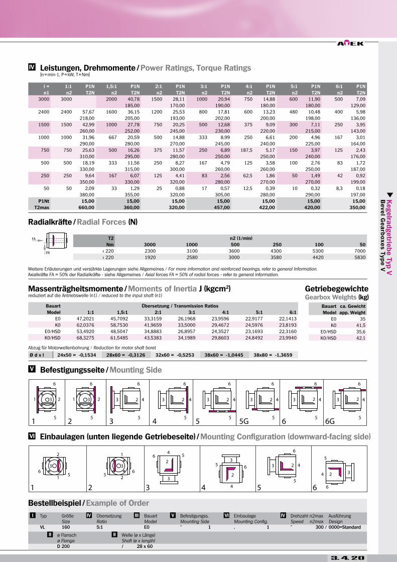
3. 4. 20
Ø d x l 24x50 = -0,1534 28x60 = -0,3126 32x60 = -0,5253 38x60 = -1,0445 38x80 = -1,3659
i = 1:1 P1N 1,5:1 P1N 2:1 P1N 3:1 P1N 4:1 P1N 5:1 P1N 6:1 P1N
n1 n2 T2N n2 T2N n2 T2N n2 T2N n2 T2N n2 T2N n2 T2N
3000 3000 2000 40,78 1500 28,11 1000 20,94 750 14,88 600 11,90 500 7,09
185,00 170,00 190,00 180,00 180,00 129,00
2400 2400 57,67 1600 36,15 1200 25,53 800 17,81 600 13,23 480 10,48 400 5,98
218,00 205,00 193,00 202,00 200,00 198,00 136,00
1500 1500 42,99 1000 27,78 750 20,25 500 12,68 375 9,09 300 7,11 250 3,95
260,00 252,00 245,00 230,00 220,00 215,00 143,00
1000 1000 31,96 667 20,59 500 14,88 333 8,99 250 6,61 200 4,96 167 3,01
290,00 280,00 270,00 245,00 240,00 225,00 164,00
750 750 25,63 500 16,26 375 11,57 250 6,89 187,5 5,17 150 3,97 125 2,43
310,00 295,00 280,00 250,00 250,00 240,00 176,00
500 500 18,19 333 11,56 250 8,27 167 4,79 125 3,58 100 2,76 83 1,72
330,00 315,00 300,00 260,00 260,00 250,00 187,00
250 250 9,64 167 6,07 125 4,41 83 2,56 62,5 1,86 50 1,49 42 0,92
350,00 330,00 320,00 280,00 270,00 270,00 199,00
50 50 2,09 33 1,29 25 0,88 17 0,57 12,5 0,39 10 0,32 8,3 0,18
380,00 355,00 320,00 305,00 280,00 290,00 197,00
P1Nt 15,00 15,00 15,00 15,00 15,00 15,00 15,00
T2max 660,00 360,00 320,00 457,00 422,00 420,00 350,00
T2 n2 (1/min)
Nm 3000 1000 500 250 100 50
< 220 2300 3100 3600 4300 5300 7000
> 220 1920 2580 3000 3580 4420 5830
Bauart Übersetzung / Transmission Ratios
Model 1:1 1,5:1 2:1 3:1 4:1 5:1 6:1
E0 47,2021 45,7092 33,3159 26,1968 23,9596 22,9177 22,1413
K0 62,0376 58,7530 41,9659 33,5000 29,4672 24,5976 23,8193
E0/HSD 53,4920 48,5047 34,8883 26,8957 24,3527 23,1693 22,3160
K0/HSD 68,3275 61,5485 43,5383 34,1989 29,8603 24,8492 23,9940
Bauart ca. Gewicht
Model app. Weight
E0 35
K0 41,5
E0/HSD 35,6
K0/HSD 42,1
Massenträgheitsmomente / Moments of Inertia J (kgcm2)reduziert auf die Antriebswelle (n1) / reduced to the input shaft (n1)
Getriebegewichte Gearbox Weights (kg)
Radialkräfte / Radial Forces (N)
Leistungen, Drehmomente / Power Ratings, Torque Ratings [n = min-1, P = kW, T = Nm]
Einbaulagen (unten liegende Getriebeseite) / Mounting Configuration (downward-facing side)
Befestigungsseite / Mounting Side
Bestellbeispiel / Example of Order
Typ
VL
GrößeSize160
ÜbersetzungRatio5:1
BauartModelE0
Befestigungss.Mounting Side
EinbaulageMounting Config.. 1
Drehzahl n2maxSpeed n2max
AusführungDesign0000=Standard
ø Flanschø FlangeD 200
Welle (ø x Länge) Shaft (ø x length)/ 28 x 60
Weitere Erläuterungen und verstärkte Lagerungen siehe Allgemeines / For more information and reinforced bearings, refer to general Information.Axialkräfte FA = 50% der Radialkräfte - siehe Allgemeines / Axial forces FA = 50% of radial forces - refer to general information.
Abzug für Motorwellenbohrung / Reduction for motor shaft boret
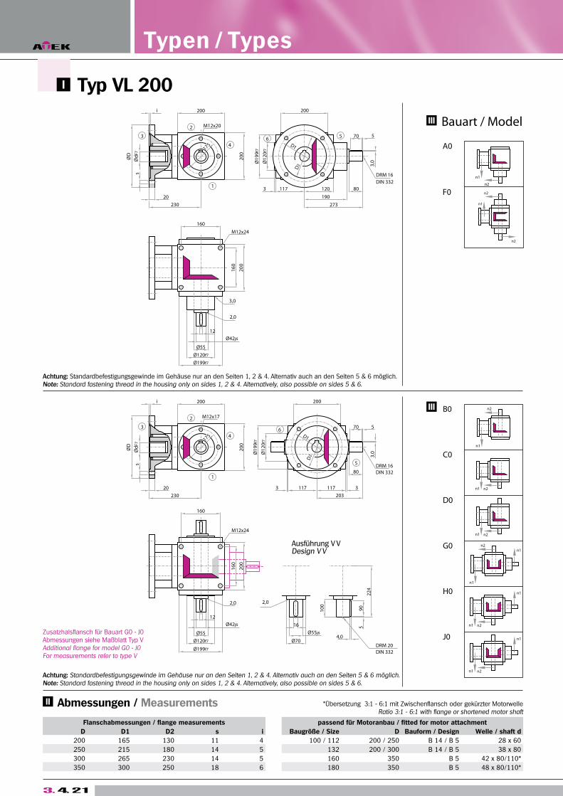
Typ VL 200 A
3. 4. 21
Zusatzhalsflansch für Bauart G0 - J0 Abmessungen siehe Maßblatt Typ VAdditional flange for model G0 - J0For measurements refer to type V
Achtung: Standardbefestigungsgewinde im Gehäuse nur an den Seiten 1, 2 & 4. Alternativ auch an den Seiten 5 & 6 möglich.Note: Standard fastening thread in the housing only on sides 1, 2 & 4. Alternatively, also possible on sides 5 & 6.
Achtung: Standardbefestigungsgewinde im Gehäuse nur an den Seiten 1, 2 & 4. Alternativ auch an den Seiten 5 & 6 möglich.Note: Standard fastening thread in the housing only on sides 1, 2 & 4. Alternatively, also possible on sides 5 & 6.
Flanschabmessungen / flange measurements passend für Motoranbau / fitted for motor attachment
D D1 D2 s i Baugröße / Size D Bauform / Design Welle / shaft d
200 165 130 11 4 100 / 112 200 / 250 B 14 / B 5 28 x 60
250 215 180 14 5 132 200 / 300 B 14 / B 5 38 x 80
300 265 230 14 5 160 350 B 5 42 x 80/110*
350 300 250 18 6 180 350 B 5 48 x 80/110*
Typen / Types
*Übersetzung 3:1 - 6:1 mit Zwischenflansch oder gekürzter MotorwelleRatio 3:1 - 6:1 with flange or shortened motor shaft
Abmessungen / Measurements
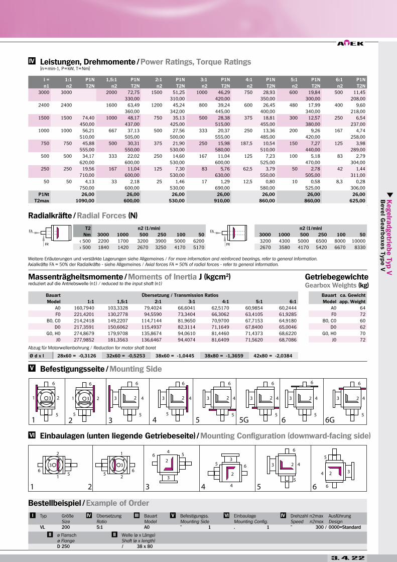
Kegelra
dgetrie
be T
yp V
B
eve
l Ge
arb
oxe
s T
yp
e V
T2 n2 (1/min) n2 (1/min)
Nm 3000 1000 500 250 100 50 3000 1000 500 250 100 50
< 500 2200 1700 3200 3900 5000 6200 3200 4300 5000 6500 8000 10000
> 500 1840 1420 2670 3250 4170 5170 2670 3580 4170 5420 6670 8330
3. 4. 22
Ø d x l 28x60 = -0,3126 32x60 = -0,5253 38x60 = -1,0445 38x80 = -1,3659 42x80 = -2,0384
i = 1:1 P1N 1,5:1 P1N 2:1 P1N 3:1 P1N 4:1 P1N 5:1 P1N 6:1 P1N
n1 n2 T2N n2 T2N n2 T2N n2 T2N n2 T2N n2 T2N n2 T2N
3000 3000 2000 72,75 1500 51,25 1000 46,29 750 28,93 600 19,84 500 11,45
330,00 310,00 420,00 350,00 300,00 208,00
2400 2400 1600 63,49 1200 45,24 800 39,24 600 26,45 480 17,99 400 9,60
360,00 342,00 445,00 400,00 340,00 218,00
1500 1500 74,40 1000 48,17 750 35,13 500 28,38 375 18,81 300 12,57 250 6,54
450,00 437,00 425,00 515,00 455,00 380,00 237,00
1000 1000 56,21 667 37,13 500 27,56 333 20,37 250 13,36 200 9,26 167 4,74
510,00 505,00 500,00 555,00 485,00 420,00 258,00
750 750 45,88 500 30,31 375 21,90 250 15,98 187,5 10,54 150 7,27 125 3,98
555,00 550,00 530,00 580,00 510,00 440,00 289,00
500 500 34,17 333 22,02 250 14,60 167 11,04 125 7,23 100 5,18 83 2,79
620,00 600,00 530,00 600,00 525,00 470,00 304,00
250 250 19,56 167 11,04 125 7,30 83 5,76 62,5 3,79 50 2,78 42 1,44
710,00 600,00 530,00 630,00 550,00 505,00 311,00
50 50 4,13 33 2,18 25 1,46 17 1,29 12,5 0,80 10 0,58 8,3 0,28
750,00 600,00 530,00 690,00 580,00 525,00 306,00
P1Nt 26,00 26,00 26,00 26,00 26,00 26,00 26,00
T2max 1090,00 600,00 530,00 910,00 860,00 860,00 625,00
Bauart Übersetzung / Transmission Ratios
Model 1:1 1,5:1 2:1 3:1 4:1 5:1 6:1
A0 160,7940 103,3328 79,4024 66,6041 62,5170 60,9854 60,2444
F0 221,4201 130,2778 94,5590 73,3404 66,3062 63,4105 61,9285
B0, C0 214,2418 149,2207 114,7144 81,9650 70,9700 67,7153 64,9180
D0 217,3591 150,6062 115,4937 82,3114 71,1649 67,8400 65,0046
G0, H0 274,8679 179,9708 135,8674 94,0610 81,4460 71,4373 68,6220
J0 277,9852 181,3563 136,6467 94,4074 81,6409 71,5620 68,7086
Bauart ca. Gewicht
Model app. Weight
A0 64
F0 72
B0, C0 60
D0 62
G0, H0 70
J0 72
Massenträgheitsmomente / Moments of Inertia J (kgcm2)reduziert auf die Antriebswelle (n1) / reduced to the input shaft (n1)
Getriebegewichte Gearbox Weights (kg)
Radialkräfte / Radial Forces (N)
Leistungen, Drehmomente / Power Ratings, Torque Ratings [n = min-1, P = kW, T = Nm]
Einbaulagen (unten liegende Getriebeseite) / Mounting Configuration (downward-facing side)
Befestigungsseite / Mounting Side
Bestellbeispiel / Example of Order
Typ
VL
GrößeSize200
ÜbersetzungRatio5:1
BauartModelA0
Befestigungss.Mounting Side
EinbaulageMounting Config.. 1
Drehzahl n2maxSpeed n2max
AusführungDesign0000=Standard
ø Flanschø FlangeD 250
Welle (ø x Länge) Shaft (ø x length)
Weitere Erläuterungen und verstärkte Lagerungen siehe Allgemeines / For more information and reinforced bearings, refer to general Information.Axialkräfte FA = 50% der Radialkräfte - siehe Allgemeines / Axial forces FA = 50% of radial forces - refer to general information.
Abzug für Motorwellenbohrung / Reduction for motor shaft boret
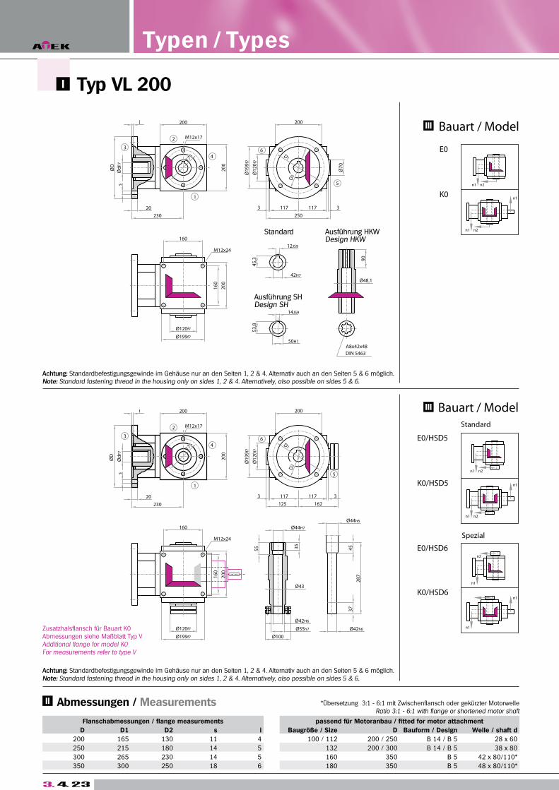
3. 4. 23
Zusatzhalsflansch für Bauart K0Abmessungen siehe Maßblatt Typ VAdditional flange for model K0For measurements refer to type V
Typ VL 200 A
Achtung: Standardbefestigungsgewinde im Gehäuse nur an den Seiten 1, 2 & 4. Alternativ auch an den Seiten 5 & 6 möglich.Note: Standard fastening thread in the housing only on sides 1, 2 & 4. Alternatively, also possible on sides 5 & 6.
Achtung: Standardbefestigungsgewinde im Gehäuse nur an den Seiten 1, 2 & 4. Alternativ auch an den Seiten 5 & 6 möglich.Note: Standard fastening thread in the housing only on sides 1, 2 & 4. Alternatively, also possible on sides 5 & 6.
Flanschabmessungen / flange measurements passend für Motoranbau / fitted for motor attachment
D D1 D2 s i Baugröße / Size D Bauform / Design Welle / shaft d
200 165 130 11 4 100 / 112 200 / 250 B 14 / B 5 28 x 60
250 215 180 14 5 132 200 / 300 B 14 / B 5 38 x 80
300 265 230 14 5 160 350 B 5 42 x 80/110*
350 300 250 18 6 180 350 B 5 48 x 80/110*
Typen / Types
*Übersetzung 3:1 - 6:1 mit Zwischenflansch oder gekürzter MotorwelleRatio 3:1 - 6:1 with flange or shortened motor shaft
Abmessungen / Measurements
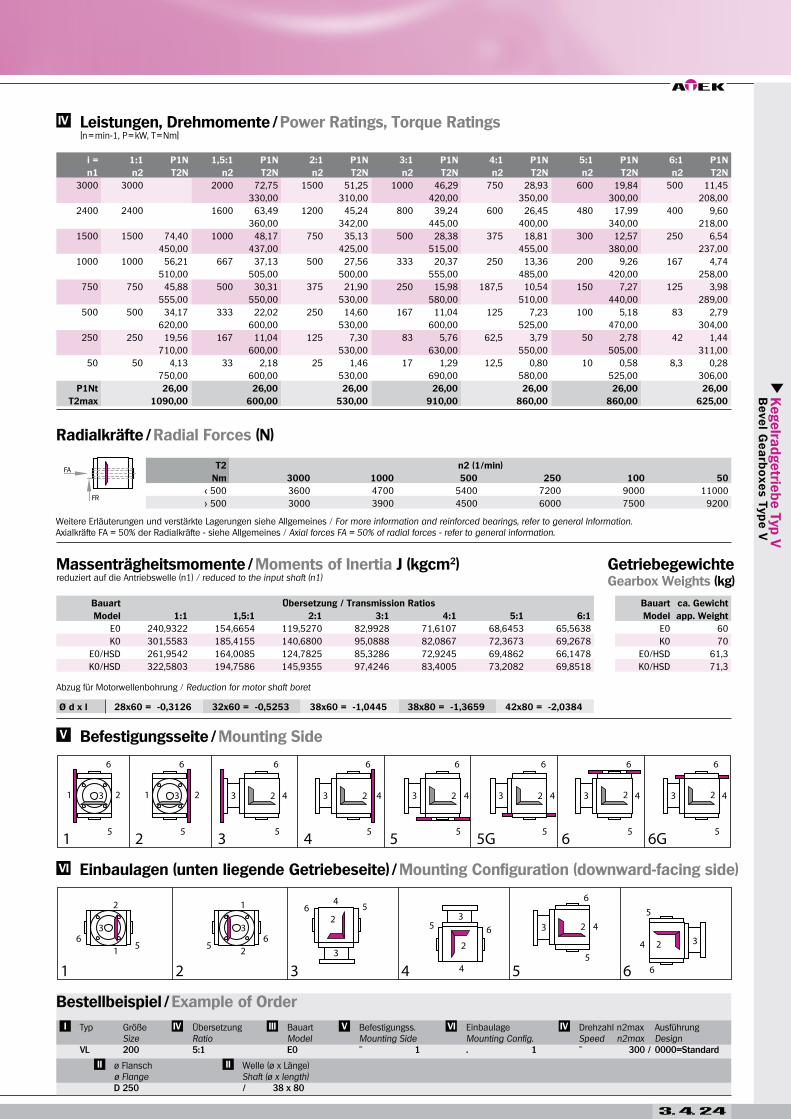
Kegelra
dgetrie
be T
yp V
B
eve
l Ge
arb
oxe
s T
yp
e V
3. 4. 24
Ø d x l 28x60 = -0,3126 32x60 = -0,5253 38x60 = -1,0445 38x80 = -1,3659 42x80 = -2,0384
i = 1:1 P1N 1,5:1 P1N 2:1 P1N 3:1 P1N 4:1 P1N 5:1 P1N 6:1 P1N
n1 n2 T2N n2 T2N n2 T2N n2 T2N n2 T2N n2 T2N n2 T2N
3000 3000 2000 72,75 1500 51,25 1000 46,29 750 28,93 600 19,84 500 11,45
330,00 310,00 420,00 350,00 300,00 208,00
2400 2400 1600 63,49 1200 45,24 800 39,24 600 26,45 480 17,99 400 9,60
360,00 342,00 445,00 400,00 340,00 218,00
1500 1500 74,40 1000 48,17 750 35,13 500 28,38 375 18,81 300 12,57 250 6,54
450,00 437,00 425,00 515,00 455,00 380,00 237,00
1000 1000 56,21 667 37,13 500 27,56 333 20,37 250 13,36 200 9,26 167 4,74
510,00 505,00 500,00 555,00 485,00 420,00 258,00
750 750 45,88 500 30,31 375 21,90 250 15,98 187,5 10,54 150 7,27 125 3,98
555,00 550,00 530,00 580,00 510,00 440,00 289,00
500 500 34,17 333 22,02 250 14,60 167 11,04 125 7,23 100 5,18 83 2,79
620,00 600,00 530,00 600,00 525,00 470,00 304,00
250 250 19,56 167 11,04 125 7,30 83 5,76 62,5 3,79 50 2,78 42 1,44
710,00 600,00 530,00 630,00 550,00 505,00 311,00
50 50 4,13 33 2,18 25 1,46 17 1,29 12,5 0,80 10 0,58 8,3 0,28
750,00 600,00 530,00 690,00 580,00 525,00 306,00
P1Nt 26,00 26,00 26,00 26,00 26,00 26,00 26,00
T2max 1090,00 600,00 530,00 910,00 860,00 860,00 625,00
T2 n2 (1/min)
Nm 3000 1000 500 250 100 50
< 500 3600 4700 5400 7200 9000 11000
> 500 3000 3900 4500 6000 7500 9200
Bauart Übersetzung / Transmission Ratios
Model 1:1 1,5:1 2:1 3:1 4:1 5:1 6:1
E0 240,9322 154,6654 119,5270 82,9928 71,6107 68,6453 65,5638
K0 301,5583 185,4155 140,6800 95,0888 82,0867 72,3673 69,2678
E0/HSD 261,9542 164,0085 124,7825 85,3286 72,9245 69,4862 66,1478
K0/HSD 322,5803 194,7586 145,9355 97,4246 83,4005 73,2082 69,8518
Bauart ca. Gewicht
Model app. Weight
E0 60
K0 70
E0/HSD 61,3
K0/HSD 71,3
Massenträgheitsmomente / Moments of Inertia J (kgcm2)reduziert auf die Antriebswelle (n1) / reduced to the input shaft (n1)
Getriebegewichte Gearbox Weights (kg)
Radialkräfte / Radial Forces (N)
Leistungen, Drehmomente / Power Ratings, Torque Ratings [n = min-1, P = kW, T = Nm]
Einbaulagen (unten liegende Getriebeseite) / Mounting Configuration (downward-facing side)
Befestigungsseite / Mounting Side
Bestellbeispiel / Example of Order
Typ
VL
GrößeSize200
ÜbersetzungRatio5:1
BauartModelE0
Befestigungss.Mounting Side
EinbaulageMounting Config.. 1
Drehzahl n2maxSpeed n2max
AusführungDesign0000=Standard
ø Flanschø FlangeD 250
Welle (ø x Länge) Shaft (ø x length)
Weitere Erläuterungen und verstärkte Lagerungen siehe Allgemeines / For more information and reinforced bearings, refer to general Information.Axialkräfte FA = 50% der Radialkräfte - siehe Allgemeines / Axial forces FA = 50% of radial forces - refer to general information.
Abzug für Motorwellenbohrung / Reduction for motor shaft boret
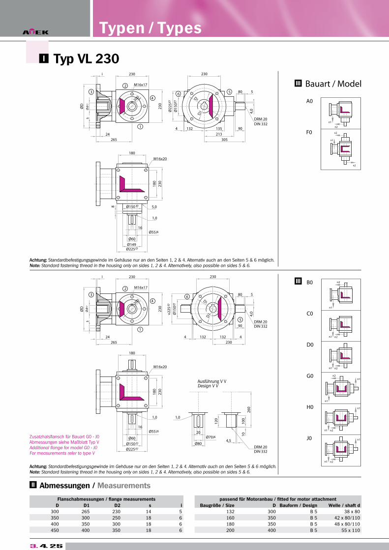
Typ VL 230 A
Zusatzhalsflansch für Bauart G0 - J0 Abmessungen siehe Maßblatt Typ VAdditional flange for model G0 - J0For measurements refer to type V
Achtung: Standardbefestigungsgewinde im Gehäuse nur an den Seiten 1, 2 & 4. Alternativ auch an den Seiten 5 & 6 möglich.Note: Standard fastening thread in the housing only on sides 1, 2 & 4. Alternatively, also possible on sides 5 & 6.
Achtung: Standardbefestigungsgewinde im Gehäuse nur an den Seiten 1, 2 & 4. Alternativ auch an den Seiten 5 & 6 möglich.Note: Standard fastening thread in the housing only on sides 1, 2 & 4. Alternatively, also possible on sides 5 & 6.
Flanschabmessungen / flange measurements passend für Motoranbau / fitted for motor attachment
D D1 D2 s i Baugröße / Size D Bauform / Design Welle / shaft d
300 265 230 14 5 132 300 B 5 38 x 80
350 300 250 18 6 160 350 B 5 42 x 80/110
400 350 300 18 6 180 350 B 5 48 x 80/110
450 400 350 18 6 200 400 B 5 55 x 110
Typen / Types
Abmessungen / Measurements
1
s
ØD
3
s
ØD
3
i
2
46
2
1
i
46
5
DIN 332
5
DIN 332
DIN 332
230
Ø60
16
1,0
Ø80
20
23
0
M16x20
23
0
180
24
265
18
0
230
200
M16x17
4 132
M16x202
30
16
1,0
5,0
180
24
265
18
0
4 132
23
0
230
200
M16x17
230
10
01
0
4,5
12
0
DRM 20
230
132 4
80
90DRM 20
4,0
5
90
213
135
305
80 5
DRM 20
4,0
1,0
26
0
Ø2
25
f7
Ø1
50
f7
D2
D1
Ø55 j6
Ø225 f7
Ø1
50
f7
v2
25
f7
D2
Ø150 f7
Ø225 f7
Ø55 j6
Ø70 j6
D1
Ø149
f7Ø1508
Ø60
Ausführung V VDesign V V
3. 4. 25
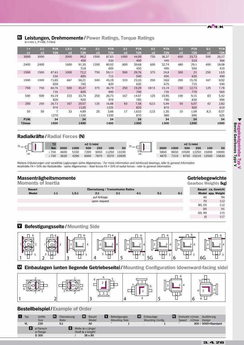
Kegelra
dgetrie
be T
yp V
B
eve
l Ge
arb
oxe
s T
yp
e V
T2 n2 (1/min) n2 (1/min)
Nm 3000 1000 500 250 100 50 3000 1000 500 250 100 50
< 750 4600 5150 7200 9450 11250 13100 5850 8650 10500 12250 15000 19000
> 750 3830 4290 6000 7870 9370 10920 4870 7210 8750 10210 12500 15830
i = 1:1 P1N 1,5:1 P1N 2:1 P1N 3:1 P1N 4:1 P1N 5:1 P1N 6:1 P1N
n1 n2 T2N n2 T2N n2 T2N n2 T2N n2 T2N n2 T2N n2 T2N
3000 3000 2000 99,2 1500 87,63 1000 44,09 750 36,37 600 33,73 500 20,17
450 530 400 440 510 366
2400 2400 1600 91,35 1200 80,02 800 39,68 600 32,74 480 29,1 400 18,08
518 605 450 495 550 410
1500 1500 87,63 1000 72,2 750 59,11 500 29,76 375 24,8 300 21 250 13,5
530 655 715 540 600 635 490
1000 1000 71,65 667 56,21 500 45,19 333 23,33 250 18,6 200 15,76 167 9,92
650 765 820 635 675 715 540
750 750 60,76 500 45,47 375 36,79 250 19,29 187,5 15,19 150 12,73 125 7,78
735 825 890 700 735 770 565
500 500 45,19 333 33,79 250 26,73 167 14,07 125 10,95 100 9,15 83 5,42
820 920 970 765 795 830 590
250 250 26,73 167 20,57 125 16,88 83 7,58 62,5 5,99 50 5,07 42 2,82
970 1120 1225 825 870 920 610
50 50 7 33 4,89 25 3,66 17 1,633 12,5 1,35 10 1,09 8,3 0,57
1270 1330 1330 870 980 990 625
P1Nt 34 34 34 34 34 34 34
T2max 1500 1400 1400 1300 1300 1200 1000
Bauart ca, Gewicht
Model app, Weight
A0 94
F0 112
B0, C0 112
D0 91
G0, H0 115
J0 117
Getriebegewichte Gearbox Weights (kg)
Radialkräfte / Radial Forces (N)
Leistungen, Drehmomente / Power Ratings, Torque Ratings [n = min-1, P = kW, T = Nm]
Einbaulagen (unten liegende Getriebeseite) / Mounting Configuration (downward-facing side)
Befestigungsseite / Mounting Side
Bestellbeispiel / Example of Order
Typ
VL
GrößeSize
ÜbersetzungRatio5:1
BauartModelA0
Befestigungss.Mounting Side
EinbaulageMounting Config.. 1
Drehzahl n2maxSpeed n2max
AusführungDesign0000=Standard
ø Flanschø Flange
Welle (ø x Länge) Shaft (ø x length)
Weitere Erläuterungen und verstärkte Lagerungen siehe Allgemeines / For more information and reinforced bearings, refer to general Information.Axialkräfte FA = 50% der Radialkräfte - siehe Allgemeines / Axial forces FA = 50% of radial forces - refer to general information.
3. 4. 26
Bauart Übersetzung / Transmission Ratios
Model 1:1 1,5:1 2:1 3:1 4:1 5:1 6:1
auf Anfrage
upon request
MassenträgheitsmomenteMoments of Inertia
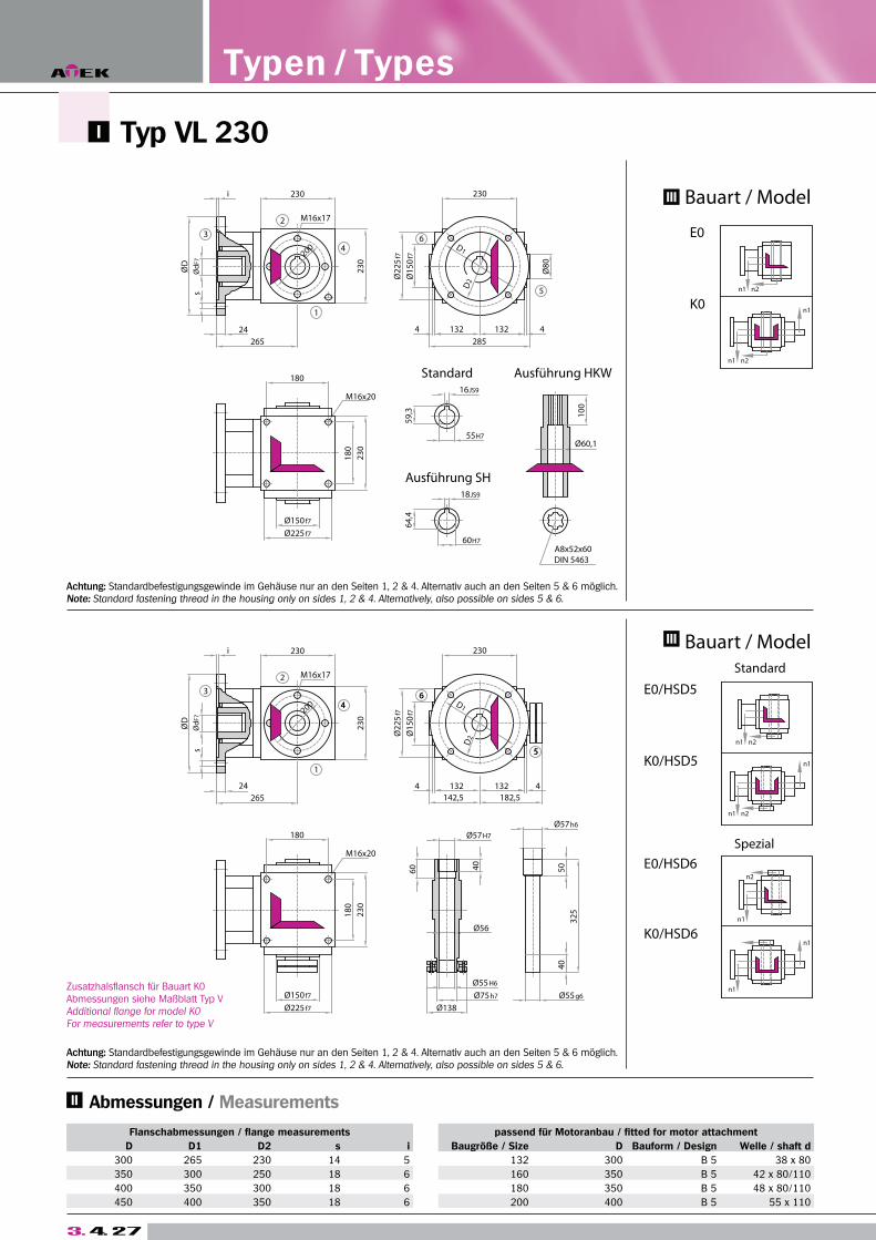
Zusatzhalsflansch für Bauart K0Abmessungen siehe Maßblatt Typ VAdditional flange for model K0For measurements refer to type V
Typ VL 230 A
Achtung: Standardbefestigungsgewinde im Gehäuse nur an den Seiten 1, 2 & 4. Alternativ auch an den Seiten 5 & 6 möglich.Note: Standard fastening thread in the housing only on sides 1, 2 & 4. Alternatively, also possible on sides 5 & 6.
Achtung: Standardbefestigungsgewinde im Gehäuse nur an den Seiten 1, 2 & 4. Alternativ auch an den Seiten 5 & 6 möglich.Note: Standard fastening thread in the housing only on sides 1, 2 & 4. Alternatively, also possible on sides 5 & 6.
Flanschabmessungen / flange measurements passend für Motoranbau / fitted for motor attachment
D D1 D2 s i Baugröße / Size D Bauform / Design Welle / shaft d
300 265 230 14 5 132 300 B 5 38 x 80
350 300 250 18 6 160 350 B 5 42 x 80/110
400 350 300 18 6 180 350 B 5 48 x 80/110
450 400 350 18 6 200 400 B 5 55 x 110
Typen / Types
Abmessungen / Measurements
n1
n1
n2
n1
E0/HSD5
E0/HSD6
Bauart / Model
Bauart / Model
n2n1
W
E0
n2n1
K0/HSD5
K0/HSD6
n1 n2
n1
K0
n1 n2
n1
Standard
Spezial
Ausführung SH
Standard
1
s
ØD
3
s
ØD
3
i
2
46
2
1
i
46
D2
D1
5
Ausführung HKW
D1
5
DIN 5463
D2
132
16JS9
132
142,5
60
Ø225 f7
Ø150 f7
Ø138
18
0
23
0
180
200
M16x17
230
23
0
Ø1
50
f7
Ø2
25
f7
M16x20
4
46
Ø225 f7
Ø150 f7
180
23
0
18
0
64
,4
M16x20
59
,3
4
200
M16x17
230
Ø2
25
f7
23
0
Ø1
50
f7
40
50
Ø75h7
Ø55H6
Ø56
Ø55g6
40
32
5
Ø57H7
182,5
132
Ø57h6
4
5
230
A8x52x60
Ø60,1
60H7
18JS9
55H7
285
132
10
0
4
230
Ø8
0
24
265
265
24
3. 4. 27
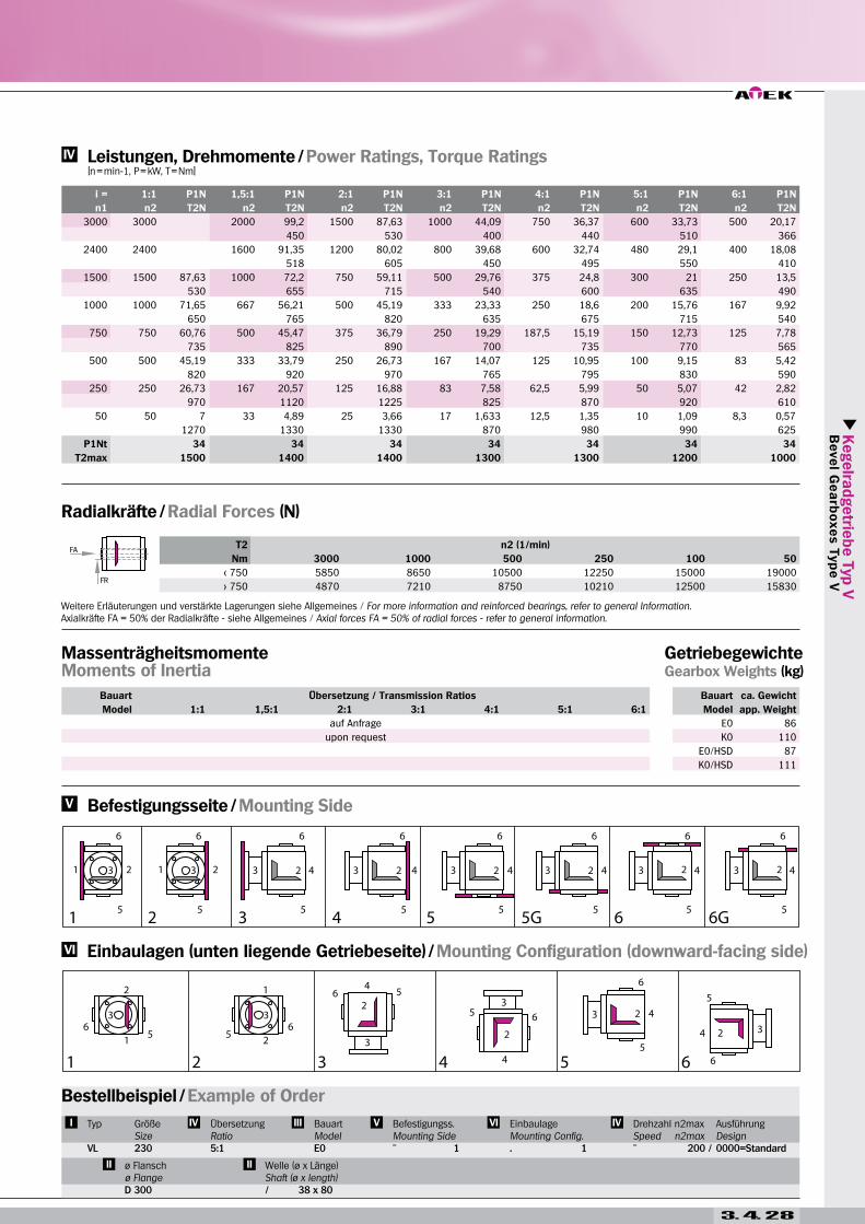
Kegelra
dgetrie
be T
yp V
B
eve
l Ge
arb
oxe
s T
yp
e V
T2 n2 (1/min)
Nm 3000 1000 500 250 100 50
< 750 5850 8650 10500 12250 15000 19000
> 750 4870 7210 8750 10210 12500 15830
Bauart ca. Gewicht
Model app. Weight
E0 86
K0 110
E0/HSD 87
K0/HSD 111
Getriebegewichte Gearbox Weights (kg)
Radialkräfte / Radial Forces (N)
Leistungen, Drehmomente / Power Ratings, Torque Ratings [n = min-1, P = kW, T = Nm]
Einbaulagen (unten liegende Getriebeseite) / Mounting Configuration (downward-facing side)
Befestigungsseite / Mounting Side
Bestellbeispiel / Example of Order
Typ
VL
GrößeSize
ÜbersetzungRatio5:1
BauartModelE0
Befestigungss.Mounting Side
EinbaulageMounting Config.. 1
Drehzahl n2maxSpeed n2max
AusführungDesign0000=Standard
ø Flanschø Flange
Welle (ø x Länge) Shaft (ø x length)
Weitere Erläuterungen und verstärkte Lagerungen siehe Allgemeines / For more information and reinforced bearings, refer to general Information.Axialkräfte FA = 50% der Radialkräfte - siehe Allgemeines / Axial forces FA = 50% of radial forces - refer to general information.
3. 4. 28
Bauart Übersetzung / Transmission Ratios
Model 1:1 1,5:1 2:1 3:1 4:1 5:1 6:1
auf Anfrage
upon request
MassenträgheitsmomenteMoments of Inertia
i = 1:1 P1N 1,5:1 P1N 2:1 P1N 3:1 P1N 4:1 P1N 5:1 P1N 6:1 P1N
n1 n2 T2N n2 T2N n2 T2N n2 T2N n2 T2N n2 T2N n2 T2N
3000 3000 2000 99,2 1500 87,63 1000 44,09 750 36,37 600 33,73 500 20,17
450 530 400 440 510 366
2400 2400 1600 91,35 1200 80,02 800 39,68 600 32,74 480 29,1 400 18,08
518 605 450 495 550 410
1500 1500 87,63 1000 72,2 750 59,11 500 29,76 375 24,8 300 21 250 13,5
530 655 715 540 600 635 490
1000 1000 71,65 667 56,21 500 45,19 333 23,33 250 18,6 200 15,76 167 9,92
650 765 820 635 675 715 540
750 750 60,76 500 45,47 375 36,79 250 19,29 187,5 15,19 150 12,73 125 7,78
735 825 890 700 735 770 565
500 500 45,19 333 33,79 250 26,73 167 14,07 125 10,95 100 9,15 83 5,42
820 920 970 765 795 830 590
250 250 26,73 167 20,57 125 16,88 83 7,58 62,5 5,99 50 5,07 42 2,82
970 1120 1225 825 870 920 610
50 50 7 33 4,89 25 3,66 17 1,633 12,5 1,35 10 1,09 8,3 0,57
1270 1330 1330 870 980 990 625
P1Nt 34 34 34 34 34 34 34
T2max 1500 1400 1400 1300 1300 1200 1000
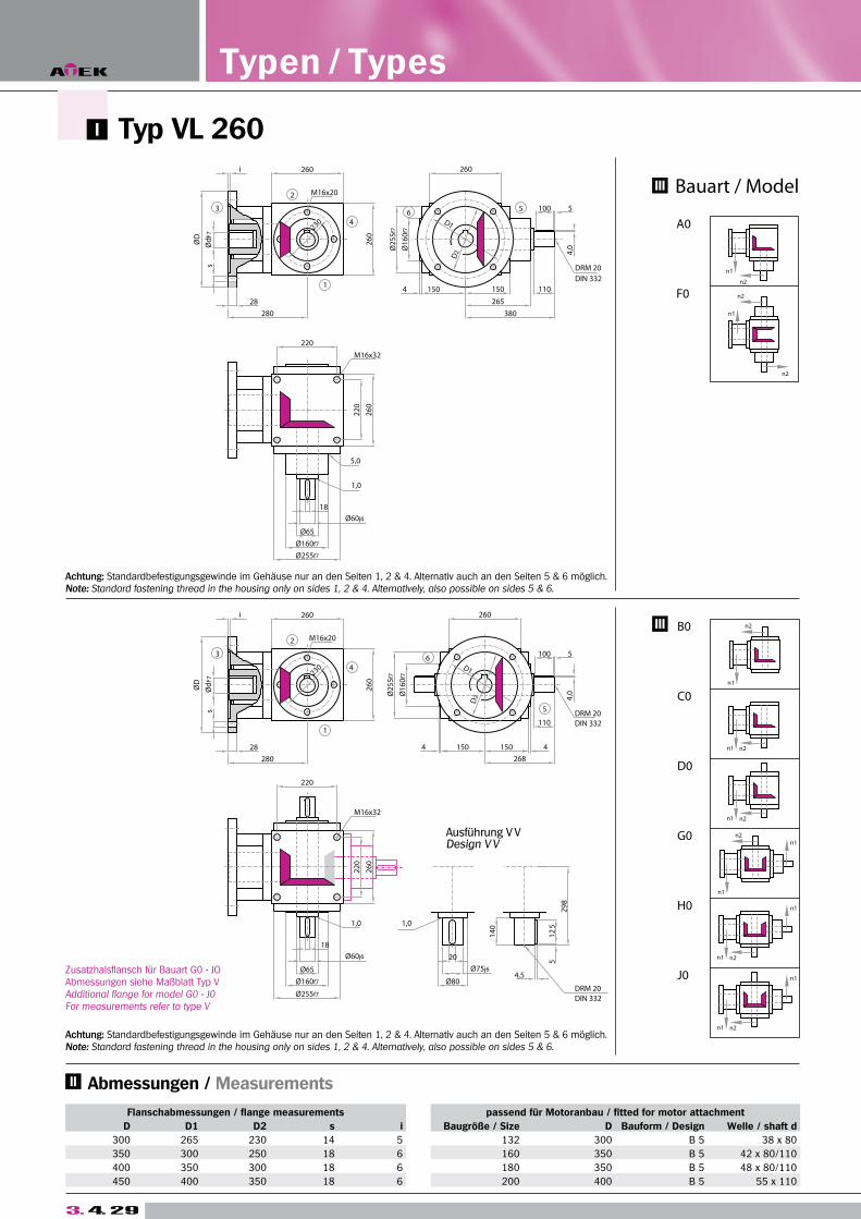
Typ VL 260
3. 4. 29
Flanschabmessungen / flange measurements passend für Motoranbau / fitted for motor attachment
D D1 D2 s i Baugröße / Size D Bauform / Design Welle / shaft d
300 265 230 14 5 132 300 B 5 38 x 80
350 300 250 18 6 160 350 B 5 42 x 80/110
400 350 300 18 6 180 350 B 5 48 x 80/110
450 400 350 18 6 200 400 B 5 55 x 110
Typen / Types
Zusatzhalsflansch für Bauart G0 - JOAbmessungen siehe Maßblatt Typ VAdditional flange for model G0 - J0For measurements refer to type V
Achtung: Standardbefestigungsgewinde im Gehäuse nur an den Seiten 1, 2 & 4. Alternativ auch an den Seiten 5 & 6 möglich.Note: Standard fastening thread in the housing only on sides 1, 2 & 4. Alternatively, also possible on sides 5 & 6.
Achtung: Standardbefestigungsgewinde im Gehäuse nur an den Seiten 1, 2 & 4. Alternativ auch an den Seiten 5 & 6 möglich.Note: Standard fastening thread in the housing only on sides 1, 2 & 4. Alternatively, also possible on sides 5 & 6.
Abmessungen / Measurements
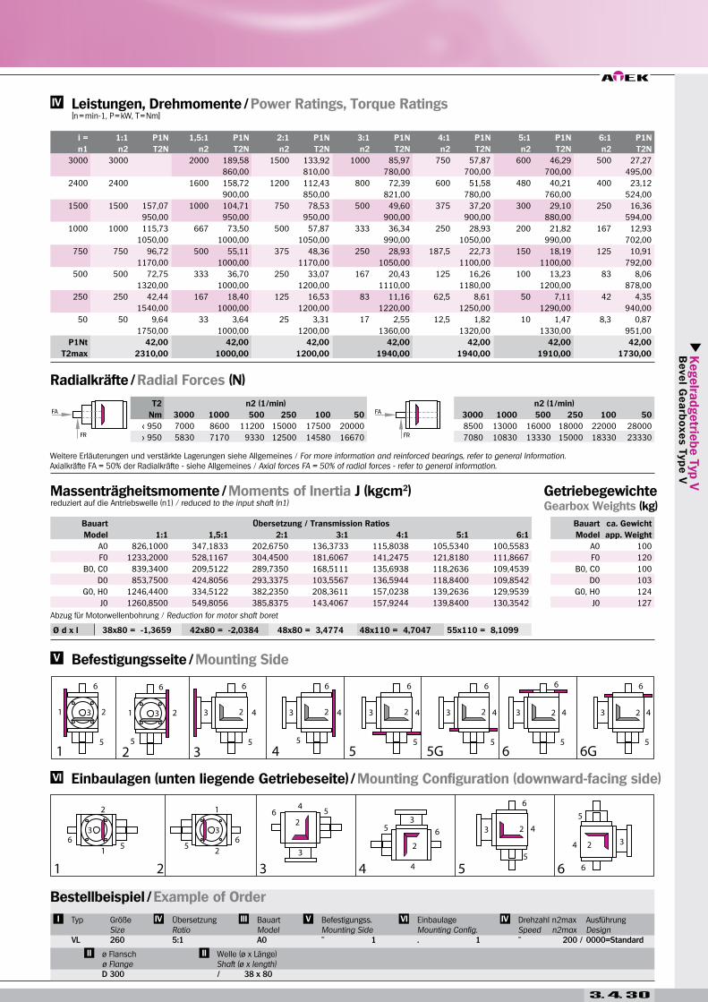
Kegelra
dgetrie
be T
yp V
B
eve
l Ge
arb
oxe
s T
yp
e V
T2 n2 (1/min) n2 (1/min)
Nm 3000 1000 500 250 100 50 3000 1000 500 250 100 50
< 950 7000 8600 11200 15000 17500 20000 8500 13000 16000 18000 22000 28000
> 950 5830 7170 9330 12500 14580 16670 7080 10830 13330 15000 18330 23330
Ø d x l 38x80 = -1,3659 42x80 = -2,0384 48x80 = 3,4774 48x110 = 4,7047 55x110 = 8,1099
i = 1:1 P1N 1,5:1 P1N 2:1 P1N 3:1 P1N 4:1 P1N 5:1 P1N 6:1 P1N
n1 n2 T2N n2 T2N n2 T2N n2 T2N n2 T2N n2 T2N n2 T2N
3000 3000 2000 189,58 1500 133,92 1000 85,97 750 57,87 600 46,29 500 27,27
860,00 810,00 780,00 700,00 700,00 495,00
2400 2400 1600 158,72 1200 112,43 800 72,39 600 51,58 480 40,21 400 23,12
900,00 850,00 821,00 780,00 760,00 524,00
1500 1500 157,07 1000 104,71 750 78,53 500 49,60 375 37,20 300 29,10 250 16,36
950,00 950,00 950,00 900,00 900,00 880,00 594,00
1000 1000 115,73 667 73,50 500 57,87 333 36,34 250 28,93 200 21,82 167 12,93
1050,00 1000,00 1050,00 990,00 1050,00 990,00 702,00
750 750 96,72 500 55,11 375 48,36 250 28,93 187,5 22,73 150 18,19 125 10,91
1170,00 1000,00 1170,00 1050,00 1100,00 1100,00 792,00
500 500 72,75 333 36,70 250 33,07 167 20,43 125 16,26 100 13,23 83 8,06
1320,00 1000,00 1200,00 1110,00 1180,00 1200,00 878,00
250 250 42,44 167 18,40 125 16,53 83 11,16 62,5 8,61 50 7,11 42 4,35
1540,00 1000,00 1200,00 1220,00 1250,00 1290,00 940,00
50 50 9,64 33 3,64 25 3,31 17 2,55 12,5 1,82 10 1,47 8,3 0,87
1750,00 1000,00 1200,00 1360,00 1320,00 1330,00 951,00
P1Nt 42,00 42,00 42,00 42,00 42,00 42,00 42,00
T2max 2310,00 1000,00 1200,00 1940,00 1940,00 1910,00 1730,00
Bauart Übersetzung / Transmission Ratios
Model 1:1 1,5:1 2:1 3:1 4:1 5:1 6:1
A0 826,1000 347,1833 202,6750 136,3733 115,8038 105,5340 100,5583
F0 1233,2000 528,1167 304,4500 181,6067 141,2475 121,8180 111,8667
B0, C0 839,3400 209,5122 289,7350 168,5111 135,6938 118,2636 109,4539
D0 853,7500 424,8056 293,3375 103,5567 136,5944 118,8400 109,8542
G0, H0 1246,4400 334,5122 382,2350 208,3611 157,0238 139,2636 129,9539
J0 1260,8500 549,8056 385,8375 143,4067 157,9244 139,8400 130,3542
Bauart ca. Gewicht
Model app. Weight
A0 100
F0 120
B0, C0 100
D0 103
G0, H0 124
J0 127
Massenträgheitsmomente / Moments of Inertia J (kgcm2)reduziert auf die Antriebswelle (n1) / reduced to the input shaft (n1)
Getriebegewichte Gearbox Weights (kg)
Radialkräfte / Radial Forces (N)
Leistungen, Drehmomente / Power Ratings, Torque Ratings [n = min-1, P = kW, T = Nm]
Einbaulagen (unten liegende Getriebeseite) / Mounting Configuration (downward-facing side)
Befestigungsseite / Mounting Side
Bestellbeispiel / Example of Order
Typ
VL
GrößeSize260
ÜbersetzungRatio5:1
BauartModelA0
Befestigungss.Mounting Side
EinbaulageMounting Config.. 1
Drehzahl n2maxSpeed n2max
AusführungDesign0000=Standard
ø Flanschø Flange
Welle (ø x Länge) Shaft (ø x length)
Weitere Erläuterungen und verstärkte Lagerungen siehe Allgemeines / For more information and reinforced bearings, refer to general Information.Axialkräfte FA = 50% der Radialkräfte - siehe Allgemeines / Axial forces FA = 50% of radial forces - refer to general information.
Abzug für Motorwellenbohrung / Reduction for motor shaft boret
3. 4. 30
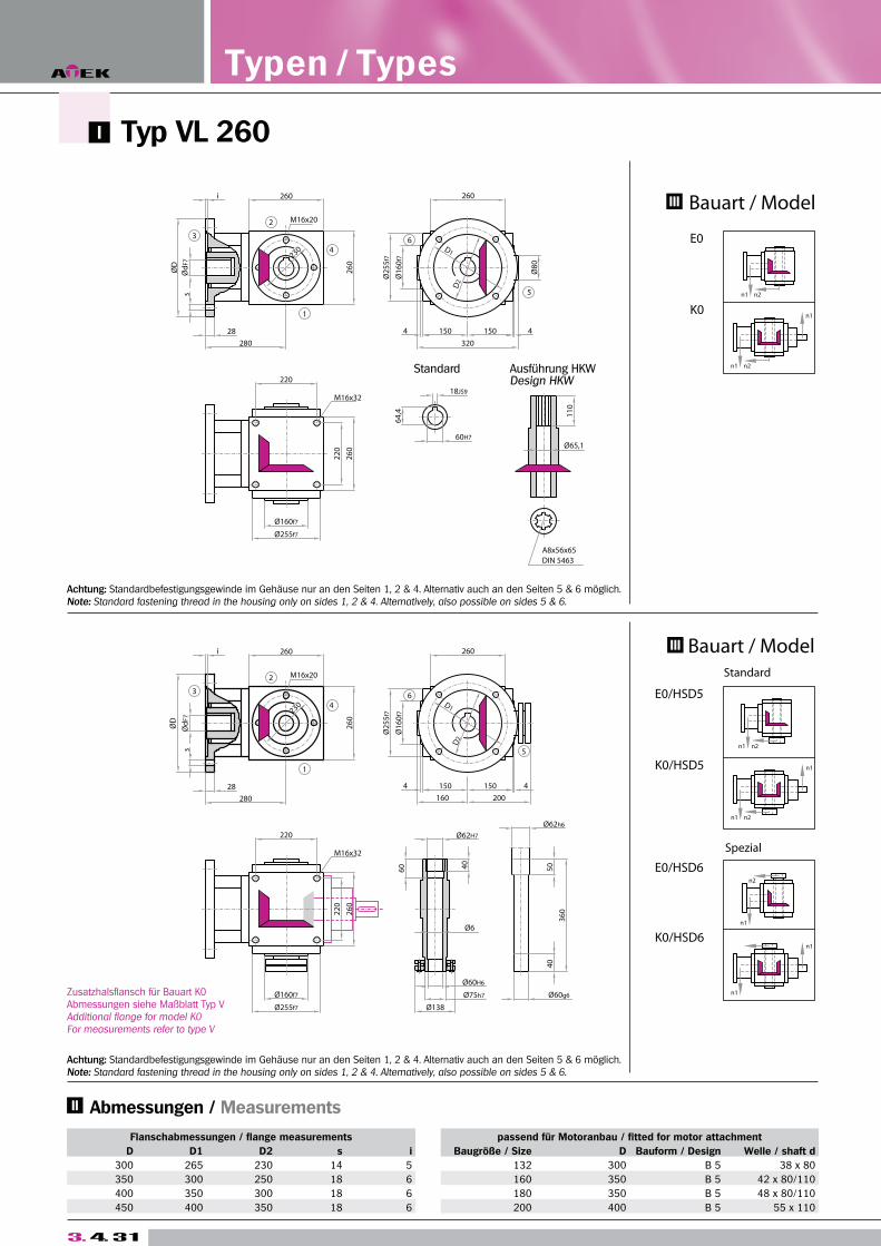
3. 4. 31
Typ VL 260 A
Flanschabmessungen / flange measurements passend für Motoranbau / fitted for motor attachment
D D1 D2 s i Baugröße / Size D Bauform / Design Welle / shaft d
300 265 230 14 5 132 300 B 5 38 x 80
350 300 250 18 6 160 350 B 5 42 x 80/110
400 350 300 18 6 180 350 B 5 48 x 80/110
450 400 350 18 6 200 400 B 5 55 x 110
Typen / Types
Zusatzhalsflansch für Bauart K0Abmessungen siehe Maßblatt Typ VAdditional flange for model K0For measurements refer to type V
Achtung: Standardbefestigungsgewinde im Gehäuse nur an den Seiten 1, 2 & 4. Alternativ auch an den Seiten 5 & 6 möglich.Note: Standard fastening thread in the housing only on sides 1, 2 & 4. Alternatively, also possible on sides 5 & 6.
Achtung: Standardbefestigungsgewinde im Gehäuse nur an den Seiten 1, 2 & 4. Alternativ auch an den Seiten 5 & 6 möglich.Note: Standard fastening thread in the housing only on sides 1, 2 & 4. Alternatively, also possible on sides 5 & 6.
Abmessungen / Measurements

Kegelra
dgetrie
be T
yp V
B
eve
l Ge
arb
oxe
s T
yp
e V
3. 4. 32
Ø d x l 38x80 = -1,3659 42x80 = -2,0384 48x80 = 3,4774 48x110 = 4,7047 55x110 = 8,1099
i = 1:1 P1N 1,5:1 P1N 2:1 P1N 3:1 P1N 4:1 P1N 5:1 P1N 6:1 P1N
n1 n2 T2N n2 T2N n2 T2N n2 T2N n2 T2N n2 T2N n2 T2N
3000 3000 2000 189,58 1500 133,92 1000 85,97 750 57,87 600 46,29 500 27,27
860,00 810,00 780,00 700,00 700,00 495,00
2400 2400 1600 158,72 1200 112,43 800 72,39 600 51,58 480 40,21 400 23,12
900,00 850,00 821,00 780,00 760,00 524,00
1500 1500 157,07 1000 104,71 750 78,53 500 49,60 375 37,20 300 29,10 250 16,36
950,00 950,00 950,00 900,00 900,00 880,00 594,00
1000 1000 115,73 667 73,50 500 57,87 333 36,34 250 28,93 200 21,82 167 12,93
1050,00 1000,00 1050,00 990,00 1050,00 990,00 702,00
750 750 96,72 500 55,11 375 48,36 250 28,93 187,5 22,73 150 18,19 125 10,91
1170,00 1000,00 1170,00 1050,00 1100,00 1100,00 792,00
500 500 72,75 333 36,70 250 33,07 167 20,43 125 16,26 100 13,23 83 8,06
1320,00 1000,00 1200,00 1110,00 1180,00 1200,00 878,00
250 250 42,44 167 18,40 125 16,53 83 11,16 62,5 8,61 50 7,11 42 4,35
1540,00 1000,00 1200,00 1220,00 1250,00 1290,00 940,00
50 50 9,64 33 3,64 25 3,31 17 2,55 12,5 1,82 10 1,47 8,3 0,87
1750,00 1000,00 1200,00 1360,00 1320,00 1330,00 951,00
P1Nt 42,00 42,00 42,00 42,00 42,00 42,00 42,00
T2max 2310,00 1000,00 1200,00 1940,00 1940,00 1910,00 1730,00
T2 n2 (1/min)
Nm 3000 1000 500 250 100 50
< 950 8500 13000 16000 18000 22000 28000
> 950 7080 10830 13330 15000 18330 23330
Bauart Übersetzung / Transmission Ratios
Model 1:1 1,5:1 2:1 3:1 4:1 5:1 6:1
E0 840,5900 454,5122 296,2975 171,4000 137,3188 119,3036 110,1761
K0 1247,6900 579,5122 388,7975 211,2500 158,6488 140,3036 130,6761
E0/HSD 904,2400 482,8011 312,2100 178,4700 141,2956 121,8488 111,9436
K0/HSD 1311,3400 607,8011 404,7100 218,3200 162,6256 142,8488 132,4436
Bauart ca. Gewicht
Model app. Weight
E0 97
K0 121
E0/HSD 99,9
K0/HSD 123,9
Massenträgheitsmomente / Moments of Inertia J (kgcm2)reduziert auf die Antriebswelle (n1) / reduced to the input shaft (n1)
Getriebegewichte Gearbox Weights (kg)
Leistungen, Drehmomente / Power Ratings, Torque Ratings [n = min-1, P = kW, T = Nm]
Einbaulagen (unten liegende Getriebeseite) / Mounting Configuration (downward-facing side)
Befestigungsseite / Mounting Side
Bestellbeispiel / Example of Order
Typ
VL
GrößeSize260
ÜbersetzungRatio5:1
BauartModelE0
Befestigungss.Mounting Side
EinbaulageMounting Config.. 1
Drehzahl n2maxSpeed n2max
AusführungDesign0000=Standard
ø Flanschø Flange
Welle (ø x Länge) Shaft (ø x length)
Weitere Erläuterungen und verstärkte Lagerungen siehe Allgemeines / For more information and reinforced bearings, refer to general Information.Axialkräfte FA = 50% der Radialkräfte - siehe Allgemeines / Axial forces FA = 50% of radial forces - refer to general information.
Abzug für Motorwellenbohrung / Reduction for motor shaft boret
Radialkräfte / Radial Forces (N)


![Quantum Algorithms for Portfolio Optimizationmethods [26]. While some of these results lack provable guarantees, they indicate the strong interest in both the quantum algorithms and](https://img.pdfslide.org/doc/110x75/5f3a7c9a8bfd266fdb74749b/quantum-algorithms-for-portfolio-optimization-methods-26-while-some-of-these.jpg)