Embed Size (px)
Citation preview
FRIEDRICH-ALEXANDER-UNIVERSITAT ERLANGEN-NURNBERG
TECHNISCHE FAKULTAT • DEPARTMENT INFORMATIK
Lehrstuhl fur Informatik 10 (Systemsimulation)
Performance Evaluation using Docker and Kubernetes
Disha Yaduraiah
Masterarbeit


Performance Evaluation using Docker and Kubernetes
Masterarbeit im Fach Computational Engineering
vorgelegt von
Disha Yaduraiah
angefertigt am
Lehrstuhl fur Informatik 10
Prof. Dr. Ulrich RudeChair of System Simulation
Dr. Andrew John Hewett Dr.-Ing. habil. Harald Kostler
Senior Software Architect ERASMUS Koordinator
Siemens Healthcare GmbH Services Department of Computer Science
Erlangen, Germany Erlangen, Germany
Aufgabensteller: Dr.-Ing. habil. Harald Kostler
Betreuer: Dipl.-Inform. Christian Godenschwager
Bearbeitungszeitraum: 01 Dez 2017 - 01 Juni 2018
Erklarung
Ich versichere, dass ich die Arbeit ohne fremde Hilfe und ohne Benutzung anderer
als der angegebenen Quellen angefertigt habe und dass die Arbeit in gleicher oder
ahnlicher Form noch keiner anderen Prufungsbehorde vorgelegen hat und von dieser
als Teil einer Prufungsleistung angenommen wurde.
Alle Ausfuhrungen, die wortlich oder sinngemaß ubernommen wurden, sind als solche
gekennzeichnet.
Declaration
I declare that the work is entirely my own and was produced with no assistance from third
parties. I certify that the work has not been submitted in the same or any similar form
for assessment to any other examining body and all references, direct and indirect, are
indicated as such and have been cited accordingly.
Erlangen, 30 May, 2018 .........................................
(Disha Yaduraiah)
iii

Abstract
Containerization technology has now made it possible to run multiple applications on the
same servers with easy packaging and shipping ability. Unlike the old techniques of hard-
ware virtualization, containers rest on the top of a single Linux instance leaving with a
light-weight image containing applications. The DevOps methodology of Continuous Inte-
gration/Continuous Delivery pipeline designed to encourage developers to integrate their
code into a shared repository early and often, and to deploy the code quickly and efficiently.
Containers combined with DevOps, are revolutionizing the way applications are built and
deployed. With cloud orchestration tool like Kubernetes, we can monitor and manage
container clustering and scheduling. Benchmarks are used to evaluate the performance of
Kubernetes cluster and discuss how High Performance Computing (HPC) applications can
be containerized using Docker and Kubernetes.
v

Acknowledgements
I would first like to thank my thesis advisor Dr.-Ing. habil. Harald Kostler at Informatik 10
Friedrich-Alexander University, Erlangen-Nurnberg. He consistently allowed this research
to be my own work, by providing timely evaluation and guidance.
I would also like to acknowledge Dr. Andrew John Hewett , Senior Project Architect at
Siemens Healthineers for giving me a chance to do my Master thesis project with Siemens
Healthineers and constantly guiding me with valuable comments. I would like to thank
Siemens AG for providing me with all necessary resources for completing my work.
I would also like to thank the experts who were involved in the validation survey for
this research project: Prof. Dr. Ulrich Rude, Head of System Simulation, Dipl.-Inform.
Christian Godenschwager. Without their passionate participation and input, the validation
survey could not have been successfully conducted.
Finally, I must express my very profound gratitude to my parents and to my friends and
family for providing me with unfailing support and continuous encouragement throughout
my years of study and through the process of researching and writing this thesis. This
accomplishment would not have been possible without them.
Thank you.
vii

Contents
Erklarung iii
Abstract v
Acknowledgements vii
1 Introduction 1
1.1 Motivation for virtualization . . . . . . . . . . . . . . . . . . . . . . . . . . 1
1.2 Overview of the Thesis . . . . . . . . . . . . . . . . . . . . . . . . . . . . . 2
1.3 Related Work . . . . . . . . . . . . . . . . . . . . . . . . . . . . . . . . . . 3
2 Background 7
2.1 Platform-as-a-Service . . . . . . . . . . . . . . . . . . . . . . . . . . . . . . 7
2.2 .NET Core Applications . . . . . . . . . . . . . . . . . . . . . . . . . . . . . 8
2.3 Virtualization Technologies . . . . . . . . . . . . . . . . . . . . . . . . . . . 9
2.4 Containerization . . . . . . . . . . . . . . . . . . . . . . . . . . . . . . . . . 11
2.4.1 Docker Containers . . . . . . . . . . . . . . . . . . . . . . . . . . . 12
2.4.2 Problems resolved using Docker . . . . . . . . . . . . . . . . . . . . 14
2.4.3 Docker Security Considerations . . . . . . . . . . . . . . . . . . . . 15
2.4.4 Performance of Containers . . . . . . . . . . . . . . . . . . . . . . . 17
2.4.5 Docker Hub . . . . . . . . . . . . . . . . . . . . . . . . . . . . . . . 19
2.5 Container-Management-System . . . . . . . . . . . . . . . . . . . . . . . . . 21
2.5.1 KUBERNETES Architecture . . . . . . . . . . . . . . . . . . . . . 22
ix
2.5.2 Creating a POD . . . . . . . . . . . . . . . . . . . . . . . . . . . . . 23
2.5.3 Kubernetes Model . . . . . . . . . . . . . . . . . . . . . . . . . . . . 25
2.5.4 Advantages of Kubernetes cluster . . . . . . . . . . . . . . . . . . . 26
3 Implementation 28
3.1 Problems in Manual Deployment . . . . . . . . . . . . . . . . . . . . . . . . 28
3.2 Deployment Pipeline . . . . . . . . . . . . . . . . . . . . . . . . . . . . . . . 29
3.3 CI/CD Pipeline . . . . . . . . . . . . . . . . . . . . . . . . . . . . . . . . . 31
3.4 Build and Release pipeline . . . . . . . . . . . . . . . . . . . . . . . . . . . 33
3.4.1 CI/CD Process Definition . . . . . . . . . . . . . . . . . . . . . . . 35
3.4.2 Installing Docker and Kubernetes . . . . . . . . . . . . . . . . . . . 37
3.5 WALBERLA Framework . . . . . . . . . . . . . . . . . . . . . . . . . . . . 39
4 Testing 42
4.1 AKS cluster (single node VM, 7GB memory) . . . . . . . . . . . . . . . . . 42
4.2 .NET Project . . . . . . . . . . . . . . . . . . . . . . . . . . . . . . . . . . . 43
4.3 UniformGrid Benchmark . . . . . . . . . . . . . . . . . . . . . . . . . . . . 45
4.3.1 Roofline model . . . . . . . . . . . . . . . . . . . . . . . . . . . . . 47
5 Conclusion 53
Bibliography 55
Appendix A 60
Appendix B 74
Appendix C 80
Curriculum Vitae 93
List of Figures
2.1 Hypervisor-based virtualization . . . . . . . . . . . . . . . . . . . . . . . . . 10
2.2 Comparison between Virtual Machines and Docker Container . . . . . . . . 11
2.3 Docker Ecosystem . . . . . . . . . . . . . . . . . . . . . . . . . . . . . . . . 13
2.4 Comparison VM Vs Containers . . . . . . . . . . . . . . . . . . . . . . . . . 18
2.5 Docker Pipeline . . . . . . . . . . . . . . . . . . . . . . . . . . . . . . . . . 19
2.6 Docker registry relationship with all users . . . . . . . . . . . . . . . . . . . 21
2.7 Kubernetes Architecture . . . . . . . . . . . . . . . . . . . . . . . . . . . . 22
2.8 Pod Flow using kubectl command . . . . . . . . . . . . . . . . . . . . . . . 24
2.9 Simplified Unified Modeling Language (UML) class diagram of the Kuber-
netes resource model . . . . . . . . . . . . . . . . . . . . . . . . . . . . . . . 25
3.1 Deployment Pipeline . . . . . . . . . . . . . . . . . . . . . . . . . . . . . . . 30
3.2 CI/CD Pipeline . . . . . . . . . . . . . . . . . . . . . . . . . . . . . . . . . 34
3.3 Build definiton . . . . . . . . . . . . . . . . . . . . . . . . . . . . . . . . . . 35
3.4 Release Pipeline . . . . . . . . . . . . . . . . . . . . . . . . . . . . . . . . . 36
3.5 Structure of Build and Release pipeline . . . . . . . . . . . . . . . . . . . . 37
3.6 Master-Slave inside Kubernetes cluster . . . . . . . . . . . . . . . . . . . . 40
4.1 Azure Kubernetes Service with autoscaler . . . . . . . . . . . . . . . . . . . 43
4.2 Outside world communication with External Load Balancer . . . . . . . . . 44
4.3 Performance results with 8 vCPUs . . . . . . . . . . . . . . . . . . . . . . . 49
4.4 Performance results with 2 vCPUs . . . . . . . . . . . . . . . . . . . . . . . 50

Chapter 1
Introduction
With the technology growing rapidly, the developer’s main focus is on virtualization, load-
balancing, scaling-out the deployments, managing dependencies, providing cross-platform
stability and capability and so on. This can be now achieved by containerization. Container
technology offers an alternative method for virtualization, in which a single operating sys-
tem (OS) on a host can run many different applications from the cloud. When compared to
virtual machines, containers provide the opportunity to virtualize the operating system it-
self. Containers offer a logical packaging mechanism in which applications can be abstracted
from the environment in which they actually run. This decoupling allows container-based
applications to be deployed easily and consistently, regardless of the target environment.
Running applications in the cloud efficiently require much more than deploying software in
virtual machines. Continuous management monitors application and infrastructural met-
rics to provide automated and responsive reactions to failures (health management) and
changing environmental conditions (auto-scaling) minimizing human intervention [1] which
is supported with an orchestrator like Kubernetes. Kubernetes is a novel architecture that
enables scalable and resilient self-management of microservices applications on the cloud.
1.1 Motivation for virtualizationThe challenges of managing a data center, including network management, hardware ac-
quisition, energy efficiency, and scalability with business demands which are costly to im-
1
2 CHAPTER 1. INTRODUCTION
plement in a way that easily expands and contracts as a function of demand. Also as
business aggregate and collaborate in global contexts, data center scalability is constrained
by cost, the ability to efficiently manage environments and satisfy regulatory requirements,
and geographic limitations. Cloud solutions can form the basis of a next-generation data
center strategy, bringing agility, elasticity, and economic viability. There are several ad-
vantages in embracing the cloud, but in essence, they typically fall into two categories
namely operational (flexibility/speed) or economical (costs) reasons. From the former per-
spective, cloud computing offers fast self-service provisioning and task automation through
APIs which allow deploying and remove resources instantly, reduce wait time for provision-
ing dev/test/production environments, enabling improved agility and time-to-market facing
business changes. Bottom line is increased productivity. From the economic perspective, the
pay-per-use model means that no upfront investment is needed for acquiring IT resources
or for maintaining them, companies pay only for effectively used resources. Virtualization
technology plays a vital role in cloud computing. In particular, benefits of virtualization
are widely employed in high-performance computing (HPC) applications. Building and de-
ploying software on high-end computing systems is a challenging task. High-performance
applications have to reliably run across multiple platforms and environments, and make use
of site-specific resources while resolving complicated software-stack dependencies. Contain-
ers are a type of lightweight virtualization technology that attempts to solve this problem
by packaging applications and their environments into standard units of software that are
portable, easy to build and deploy, and have low runtime overhead. This advantage makes
possible to rapidly deploy high-performance application benchmarks on Kubernetes from
containerized applications that have been developed, built in non-HPC commodity hard-
ware, e.g. the laptop or workstation of a researcher.
1.2 Overview of the Thesis
In time, overcoming the challenges, Docker containers was introduced. Docker is an open
source project providing a systematic way to automate the faster deployment of Linux
1.3. RELATED WORK 3
applications inside portable containers. Basically, Docker extends LinuX Containers (LXC)
with a kernel and application level API that together run processes in isolation from CPU,
memory, I/O, network, and so on. Docker also uses namespaces to completely isolate
an application’s view of the underlying operating environment, including process trees,
network, user IDs, and file systems. Docker containers are created using base images.A
Docker image can include just the operating system fundamentals, or it can consist of a
sophisticated prebuilt application stack ready for launch. The current work implements a
continuous integration/continuous deployment (CI/CD) pipeline for a multi-container app
using Azure Container Service, Kubernetes and Visual Studio Team Services (VSTS) build
and release management. .NET Core application will be deployed via a CI/CD pipeline
from a GitHub repository to a Kubernetes cluster running on Azure Container Service.
Developers have greater control over the process and can respond more quickly to market
demands by bringing up new environments, testing against them and easily starting over, if
needed. Moreover, developers can quickly adjust to new environments with this approach
that has proven to decrease failures and resolution time. Operations benefits can be obtained
due to reduced friction in the CI/CD pipeline created by automation lowering the repetitive
process, manual work and the greater opportunity to introduce efficiency into the process.
And, with less manual tasks, providing everyone with more time for strategic work, which
provides direct bottom-line value to the organization. Performance Evaluation by running
benchmark tests on Kubernetes and calculating performance overhead compared to other
simulation results.
1.3 Related Work
Containers, Docker, and Kubernetes seem to have sparked the hope of a universal cloud
application and deployment technology. An overview of the previous research works on the
importance of container virtualization for high-performance computing and need of con-
tainer management via Kubernetes.To give an basic idea to the reader, few articles are
provided with a brief description below.
4 CHAPTER 1. INTRODUCTION
Networking in Containers and Container Clusters [6]
The article provides insights on networking configurations available in Docker and explain-
ing the networking setups, its uses and pointing out the problem faced by Docker containers.
The study also shows the dependency of the containers with Kubernetes cluster. One of
the networking goals for these containers was to provide a discoverable address and not lose
performance. Considering the drawbacks of Docker, our current implementation proves the
management of the .NET Core and MPI-enabled containers within a Kubernetes cluster
without having to worry about the network configuration.
Containers and Clusters for Edge Cloud Architectures -a Technology Review [31]
The research article reviews the suitability of container technology for edge clouds and sim-
ilar settings, starting by summarizing the virtualization principles behind containers and
identifying key technical requirements of edge cloud architectures. The importance of the
new container technology for PaaS cloud concerns with application packaging and orches-
tration concerns.
An architecture for self-managing microservices [1]
The paper proposes a novel architecture that enables scalable and resilient self-management
of microservices applications on the cloud. Cloud computing offers fast self-service provi-
sioning and task automation through APIs which allow deploying and remove resources
instantly, reduce wait time for provisioning dev/test/production environments, enabling
improved agility and time-to-market facing business changes resulting in increased produc-
tivity.
Containerisation and the PaaS Cloud [33]
This article analyzes the underlying virtualization principles behind containers and ex-
plaining the inconsistencies with the virtual machines. For deploying portable, interoper-
able applications in the cloud, a lightweight distribution of applications can be done via
1.3. RELATED WORK 5
containerization. The basic ideas involved in having a lightweight portable runtime, and
capable of developing, testing and deploying applications on a large number of servers and
also managing containers interconnectivity. The paper aims to clarify how containers can
change the PaaS cloud technology as a virtualization technique. Container technology has a
huge potential to substantially advance PaaS technology towards distributed heterogeneous
clouds through lightweight property and interoperability.
Containers for portable, productive and performant scientific computing [34]
The paper focuses on how containers can ease the difficulty of sharing and distributing
scientific code to developers and end-users on a wide range of computing platforms. The
performance is considered based on distributed memory parallel programming models, so
containers performance characteristics on distributed memory machines are demonstrated.
Container technology can improve productivity and share in scientific computing commu-
nity and in particular, can dramatically improve the accessibility and usability of HPC
systems (Cray XC30). And the containers provide a portable solution on HPC systems to
the problem with languages that load a large number of small files on each process. The
experiments and results provide guidance for making containers work seamlessly and with-
out performance penalty for the vendors of HPC systems relying on third-party libraries.
Performance Evaluation of Container-based Virtualization for High Performance Comput-
ing Environments [43]
The work talks about an approach for a container-based virtualization that addresses the
usage of specialized HPC resources such as GPU accelerators and network interconnect so-
lutions by implementing extending Shifter [43], a project that provides a container runtime
built specifically to address the needs of HPC. The performance data on multiple bench-
marks have been run on a variety of HPC systems and supports the idea of portable and
high-performance containers. The proposed container-based workflow lowers the learning
curve, drastically improving user productivity and the usability of HPC systems without
6 CHAPTER 1. INTRODUCTION
incurring the loss of application performance. The scope of present work is systematically
organized into 5 different chapters for easy understanding and presentation.
Chapter 2 gives detailed explanation about the latest cloud technologies and real-world
application and its usage. Mainly dealing with Docker and Kubernetes needed for the thesis
work. Chapter 3 compares the old to new deployment architectures, its problems and pro-
vides a solution by explaining the implementation technique used in the current thesis work.
Chapter 4 calculates and evaluates the testing results from the implemented models using
various Azure VM’s sizes. The comparison is made considering the VM sizes and point-
ing out the the reasons and provide the improvements needed for improving performance.
In the Chapter 5, based on the results, a general conclusion is made which can be used
in the organization to employ these techniques to enhance their production management.
Appendix A,B,C has the full implementation code of the current work.
Chapter 2
Background
Docker containers’ meteoric rise in popularity and commercial importance is the result
of timing - a fact that in some ways mirrors the unexpected success of the Linux kernel
two decades earlier. Kubernetes is a powerful system, developed by Google, for managing
containerized applications in a clustered environment. It aims to provide better ways of
managing distributed components across the varied infrastructure.
2.1 Platform-as-a-ServiceMore than 80 percent of large organizations are actively evaluating enterprise Platform as a
Service (PaaS) and conducting a PaaS comparison for development in public, private, and
hybrid clouds. As a foundational software layer and an application run-time environment,
enterprise PaaS removes the complexities of building and delivering applications and en-
ables organizations to turn ideas into faster innovations [23]. The capability provided to
the consumer is to deploy onto the cloud infrastructure with consumer-created or acquired
applications created using programming languages, libraries, services, and tools supported
by the provider. The consumer does not manage or control the underlying cloud infras-
tructure including network, servers, operating system’s, or storage, but has control over
the deployed applications and possibly configuration settings for the application-hosting
environment [24]. For example, Microsoft Azure. The Microsoft offers a complete plat-
form on which clients can roll out their applications. Infrastructure is offered similarly to
7
8 CHAPTER 2. BACKGROUND
Information-as-a-Service (IaaS), but in contrast to IaaS, no maintenance of the servers or
operating system’s is required. Microsoft also offers the operating system (Windows Server,
Linux, etc.) as a service [22]. Here clients just have to implement the developed application
on the operating system and scaling of deployments is done automatically by the underlying
framework. No additional management of virtual machines is involved. To enable the use
of a PaaS framework, an application must be built specifically on the PaaS framework or
modified to suit this framework. We are considering.NET Core applications which pro-
vide cross-platform portability supporting less expensive Linux VM’s when compared to
Windows VM’s which are compatible with Paas framework.
2.2 .NET Core Applications
One of the challenges faced by the .NET Framework can be overcome by using .NET
Core applications. The .NET framework failed to share code across platforms but now,
with .NET Core will provide developers with a library which can be deployed over various
platforms and which also allows developers to import just the parts of the framework they
need for their projects [18]. Microsoft maintains both runtimes for building applications
with .NET, and they share many of the same APIs. This shared API is called the .NET
Standard. Developers use the .NET framework to create Windows desktop applications
and server-based applications. This includes ASP.NET web applications. .NET Core is
used to create server applications that can run on Windows, Linux, and Mac. It does
not currently support creating desktop applications with a user interface. Developers can
write applications and libraries in VB.NET, C#, and F# in both runtimes [25]. .NET
Core can be used as a cross-platform and open-source framework, and it can be used to
develop applications on any platform. Often it is used for cloud applications or refactoring
large enterprise applications into microservices. Microservices, a form of service-oriented
architecture, are software applications comprised of small, modular business services. Each
service can run a unique process, be deployed independently and be created in different
programming applications. .NET Core allows a mix of technologies, is lightweight and can
2.3. VIRTUALIZATION TECHNOLOGIES 9
be minimized for each microservice. It is scalable as new microservices are added [18].
Containers and microservices architecture often are used together. Because it is lightweight
and modular, .NET Core works very well with containers. Server apps can be deployed on
cross-platform using Docker containers. .NET Framework can be used for containers, but
the image size is larger. When installing applications with dependencies on different versions
of frameworks in.NET, developers need to use .NET Core. Multiple services can be run
on the same server with different versions of .NET. Microsoft recommends running .NET
Core with ASP.NET Core for the best performance and scale. This becomes important
when hundreds of microservices could be used [18]. A lower number of servers and virtual
machines should be needed. The efficiency and scalability gained could translate to a better
user experience in addition to cost savings. VSTS provides a highly customizable CI/CD
automation system for ASP.NET Core apps. .NET Core is a small optimized runtime that
is the basis of ASP.NET Core 5.
2.3 Virtualization Technologies
Virtualization is an answer to the need for scheduling processes as a manageable container
units. The term virtualization broadly describes the separation of a resource or request for a
service from underlying physical delivery of that service. With virtual memory, for example,
computer software gains access to more memory than if physically installed, via the back-
ground swapping of data to disk storage. Similarly, virtualization techniques can be applied
to other IT infrastructure layers including networks, storage, laptop or server hardware, op-
erating system’s and applications [27]. A key benefit of virtualization is the ability to run
multiple operating system’s on a single physical system and share the underlying hardware
resources known as partitioning. There are two types of virtualizations namely hypervisor-
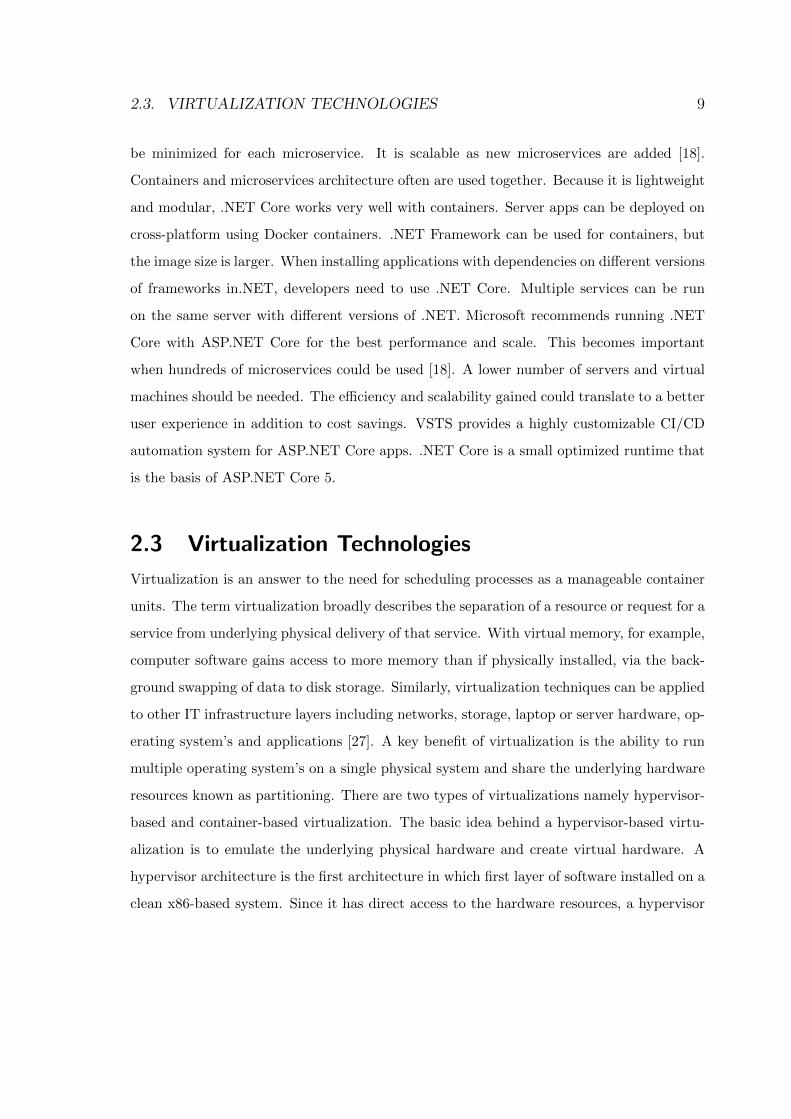
based and container-based virtualization. The basic idea behind a hypervisor-based virtu-
alization is to emulate the underlying physical hardware and create virtual hardware. A
hypervisor architecture is the first architecture in which first layer of software installed on a
clean x86-based system. Since it has direct access to the hardware resources, a hypervisor
10 CHAPTER 2. BACKGROUND
is more efficient than hosted architectures, enabling greater scalability, robustness, and per-
formance [26]. The hypervisor is available at the boot time of machine in order to control
the sharing of system resources across multiple VM’s. Some of these VM’s are privileged
partitions which manage the virtualization platform and hosted Virtual Machines. In this
architecture, the privileged partitions can view and control the VM’s. This approach es-
Figure 2.1: Hypervisor-based virtualization
tablishes the most controllable environment and can utilize additional security tools such
as intrusion detection systems [1]. However, it is vulnerable because the hypervisor has a
single point of failure. If the hypervisor crashes or the attacker gains control over it, all
VM’s under it gets compromised. However, taking control over the hypervisor from the
virtual machine level is difficult, but not impossible. The architecture of a hypervisor-based
virtualization is shown in the fig 2.1. VM’s have been improved over the years by enhanc-
ing scheduling, packaging and resource access (security). However, limitations remain. For
instance, full guest operating system images are needed for each VM in addition to binaries
2.4. CONTAINERIZATION 11
and libraries necessary for the applications, which is a space concern meaning additional
RAM and disk storage requirements. It also causes performance issues as this is slow on
startup (boot) [26].
2.4 ContainerizationThe concept of containerization was originally developed, to isolate namespaces in a Linux
operating system for security purposes. LXC (LinuX Containers) was the first, most com-
plete implementation of Linux container manager. LXC provides operating system-level
virtualization through a virtual environment that has its own process and network space,
instead of creating a full-fledged virtual machine. LXC containers faced some security
threats. At the platform service level, packaging and application management is an ad-
ditional requirement [29]. Containers can match these requirements, but a more in-depth
elicitation of specific concerns is needed.
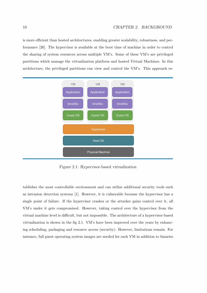
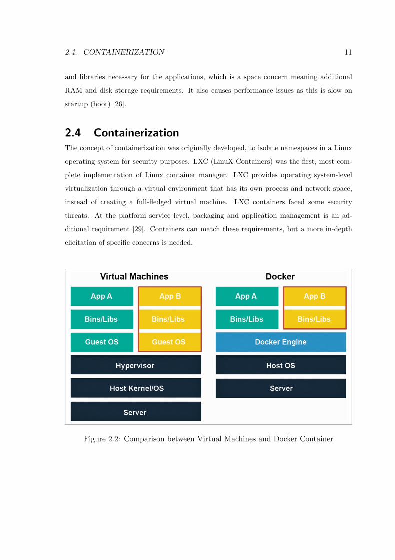
Figure 2.2: Comparison between Virtual Machines and Docker Container
12 CHAPTER 2. BACKGROUND
Container virtualization is done at the operating system level, rather than the hardware
level. Each container (as a guest operating system) shares the same kernel of the base
system [43]. As each container is sitting on top of the same kernel, and sharing most of
the base operating system, containers are much smaller and lightweight compared to a
virtualized guest operating system. As they are lightweight an operating system can have
many containers running on top of it, compared to the limited number of guest operating
system’s that could be run. Although the hypervisor-based approach to virtualization
does provide a complete isolation for the applications, it has a huge overhead (overhead of
allocating resources, the overhead of managing the size of a virtual machine). Sharing in a
virtualized environment(between guest operating system) which is very similar to sharing
between independent systems, because virtualized hosts are not aware of each other, and
the only method of sharing is via shared file system. The basic principle in container-
based virtualization is that, without virtual hardware emulation, containers can provide a
separated environment, similar to virtualization, where every container can run their own
operating system by sharing the same kernel. Each container has its own network stack,
file system etc[28].
2.4.1 Docker Containers
Docker is a computer program that performs operating system-level virtualization also
known as containerization. It is developed by Docker, Inc. Docker is primarily developed
for Linux, where it uses the resource isolation features of the Linux kernel such as cgroups
and kernel namespaces, and others to allow independent ”containers” to run within a single
Linux instance, avoiding the overhead of starting and maintaining virtual machines (VM’s).
Docker is an open-source project for automating the application’s deployment as portable,
self-sufficient containers that can run on the cloud or on-premises. A simple comparison
between VM and Container is shown below in the fig 2.2. Basically, Docker extends LXC
with a kernel-and application-level API that together runs processes in isolation: CPU,
memory, I/O, network, and so on.
2.4. CONTAINERIZATION 13
Figure 2.3: Docker Ecosystem
14 CHAPTER 2. BACKGROUND
Docker also uses namespaces to completely isolate an application’s view of the under-
lying operating environment, including process trees, user IDs, and file systems. Docker
containers are created using base images. A Docker image can include just the operating
system fundamentals, or it can consist of a sophisticated prebuilt application stack ready
for launch. When building images with Docker, each action taken (the command executed,
such as apt-get install) forms a new layer on top of the previous one. Commands can
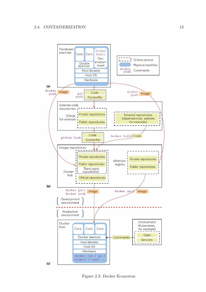
be executed manually or automatically using Dockerfiles [29]. As Figure 2.3 shows, the
Docker ecosystem includes various components. Docker provides a specification for con-
tainer images and runtime, including Dockerfiles that allow a reproducible building process
(Figure 2.3a). Docker software implements this specification using the Docker daemon,
known as the Docker engine. The repositories include a central repository, the Docker hub
that lets developers upload and share their images, along with a trademark and bindings
with third-party applications (Figure 2.3b). Finally, the build process fetches code from
external repositories and holds the packages that will be embedded in the images (Figure
2.3c). Docker is written in the Go language and was first released in March 2013.
2.4.2 Problems resolved using Docker
A Docker-based approach works similarly to a virtual machine image in addressing the
dependency problem by providing other researchers with a binary image [30]. The Docker
image is like a prebaked file system that contains a very thin layer of libraries and binaries
that are required to make the application work, and with application code and also some
supporting packages [32]. Dockerfile is a script composed of various commands (instructions)
and arguments listed successively to perform actions on a base image to create (or form)
a new image automatically [29]. This provides a consistent DevOps approach which is
the practice of documenting an application with brief descriptions of various installation
paths, along with scripts or recipes that automate the entire setup. One of the main
IT assets is to preserve the developed code through the dev test work-flow of dev test,
staging, and deployment to production environment until delivered to the customer. This
2.4. CONTAINERIZATION 15
DevOps practice provides a lightweight computing technology having code and applications
added into a resource (Ex. Dockerfile), have them be portable all the way through the dev
test, and then be able to be instantiated in production. This is now possible with Docker
containers which eliminate the problem classic ”it works on my machine” [32]. Docker is
cost-saving when compared to VM in which a large weight compute resource taking minutes
to hours for achieving CI/CD using VSTS, Jenkins can now be obtained in seconds. This
saves a lot of time, resources, CPU consumption which altogether leads to cost-saving [32].
For deploying applications with the least infrastructure a simple container-to-operating
system approach is chosen. This is why container-based cloud vendors can claim improved
performance when compared to hypervisor-based clouds. A recent benchmark of a fast data
NewSQL system claimed that in an apples-to-apples comparison, running on IBM Softlayer
using containers resulted in a fivefold performance improvement over the same benchmark
running on Amazon AWS using a hypervisor [3]. One of the containers’ nicest features is
that they can be managed specifically for application clustering, especially when used in
a PaaS environment [29]. At the June 2014 Google Developer Forum, Google announced
Kubernetes, an open source cluster manager for Docker containers [4].
2.4.3 Docker Security ConsiderationsDocker security require operating system-level virtualization relying on main factors like
isolation of processes at the userspace level, managed by the Docker daemon capable of
launching containers, control their isolation level (cgroups, namespaces, capabilities restric-
tions, and SELinux/Apparmor profiles), monitor them to trigger actions (such as restart),
and spawn shells into running containers (for administration purposes), enforcement of this
isolation by the kernel, and network operations security.
• Isolation: Docker achieves IPC (inter-process communication) isolation by using the
IPC namespaces, which allows the creation of separated IPC namespaces. The pro-
cesses in an IPC namespace cannot read or write the IPC resources in other IPC
namespaces. Docker assigns an IPC namespace to each container, thus preventing the
16 CHAPTER 2. BACKGROUND
processes in a container from interfering with those in other containers [36]. Docker’s
global security can be lowered by options which are triggered at container launch,
that give extended access to some parts of the host to containers. Additionally, secu-
rity configuration can be set globally through options passed to the Docker daemon.
This includes options lowering security, such as the -insecure-registry option, which
disables the Transport Layer Security (TLS) certificate check on a particular registry.
Options that increase security such as the icc=false parameter, which forbids net-
work communications between containers and mitigates the ARP poisoning attack
but they prevent multi-container applications from operating properly and hence are
rarely used [35].
• Network Security: Network isolation is important to prevent network-based attacks,
such as Man-in-the-Middle (MitM) and ARP spoofing. Containers must be configured
in such a way that they are unable to eavesdrop on or manipulate the network traffic
of the other containers nor the host [36]. To distribute images, Docker verifies images
downloaded from a remote repository with a hash and the connection to the registry is
made over TLS (unless explicitly specified otherwise). Moreover, the Docker Content
Trust architecture now lets developers sign their images before pushing them to a
repository [5]. For each container, Docker creates an independent networking stack
by using network namespaces. Therefore, each container has its own IP addresses,
IP routing tables, network devices, etc. This allows containers to interact with each
other through their respective network interfaces, which is as same as interacting with
external hosts. veth (virtual ethernet) creates a pair of network interfaces that act like
a pipe. The usual setup involves creating a veth pair with one of the peer interfaces
kept in the host network namespace and the other added to the container namespace.
The interface on the host network namespace is added to a network bridge [6]. With
this approach, Docker creates a virtual Ethernet bridge in the host machine, named
docker0, that automatically forwards packets between its network interfaces. When
Docker creates a new container, it also establishes a new virtual ethernet interface
2.4. CONTAINERIZATION 17
with a unique name and then connects this interface to the bridge. The interface is
also connected to the eth0 interface of the container, thus allowing the container to
send packets to the bridge.
• Limiting the resources: In an article on ”Analysis of Docker Security” specifies that
Denial-of-Service (DoS) is one of the most common attacks on a multi-tenant system,
where a process or a group of processes attempt to consume all of the system’s
resources , thus disrupting the normal operation of the other processes. In order
to prevent this kind of attack, it should be possible to limit the resources that are
allocated to each container. Cgroups are the key component that Docker employs to
deal with this issue. They control the amount of resources, such as CPU, memory, and
disk I/O, that any Docker container can use, ensuring that each container obtains its
fair share of the resources and preventing any container from consuming all resources.
They also allow Docker to configure the limits and constraints related to the resources
allocation on each container. For example, one such constraint is limiting the CPUs
available to a specific container [36].
2.4.4 Performance of ContainersBoth VM’s and containers are mature technology that has benefited from a decade of
incremental hardware and software optimizations. Today’s typical servers are NUMA, we
believe that attempting to exploit NUMA in the cloud may be more effort than it is worth.
Limiting each workload to a single socket greatly simplifies performance analysis and tuning.
Given that cloud applications are generally designed to scale-out deployments and increase
the number of cores per socket over time, the unit of scaling should probably be the socket
rather than the server. This is also a case against bare metal, since a server running one
container per socket may actually be faster than spreading the workload across sockets due
to the reduction in cross-traffic communication [8]. Comparing performance and efficiency of
containers against virtual machines, it can be inferred from the benchmark tests conducted
that VM suffer from a lot of overhead. Considering the security, VM has a slight edge
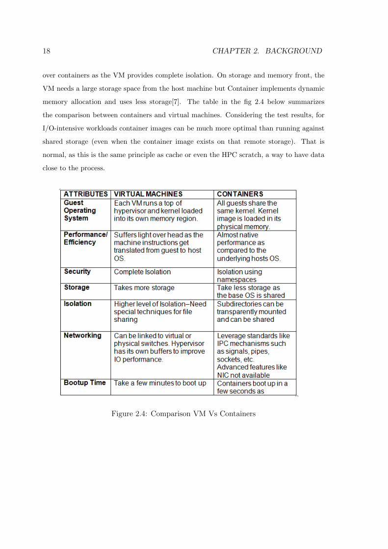
18 CHAPTER 2. BACKGROUND
over containers as the VM provides complete isolation. On storage and memory front, the
VM needs a large storage space from the host machine but Container implements dynamic
memory allocation and uses less storage[7]. The table in the fig 2.4 below summarizes
the comparison between containers and virtual machines. Considering the test results, for
I/O-intensive workloads container images can be much more optimal than running against
shared storage (even when the container image exists on that remote storage). That is
normal, as this is the same principle as cache or even the HPC scratch, a way to have data
close to the process.
Figure 2.4: Comparison VM Vs Containers
2.4. CONTAINERIZATION 19
2.4.5 Docker HubDocker consists of two major components: Docker engine and Docker Hub. The former is
an open source virtualization solution, while the latter is a Software-as-a-Service platform
for sharing Docker images [36]. Docker Hub is a cloud-based registry service which allows
user to link to code repositories, build their images and test them, stores manually pushed
images, and link to Docker Cloud so user can deploy images on hosts. It provides a central-
ized resource for container image discovery, distribution and change management, for user
and team collaboration, and also for workflow automation throughout the development
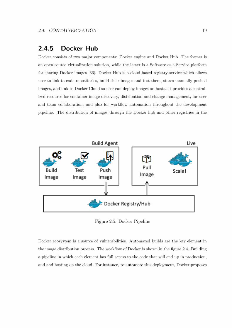
pipeline. The distribution of images through the Docker hub and other registries in the
Figure 2.5: Docker Pipeline
Docker ecosystem is a source of vulnerabilities. Automated builds are the key element in
the image distribution process. The workflow of Docker is shown in the figure 2.4. Building
a pipeline in which each element has full access to the code that will end up in production,
and and hosting on the cloud. For instance, to automate this deployment, Docker proposes
20 CHAPTER 2. BACKGROUND
automated builds on the Docker hub, triggered by an event from an external code reposi-
tory (such as GitHub). Docker then proposes to send an HTTP request to a Docker host
reachable on the Internet to notify it that a new image is available. This triggers an image
pull and a container restart on the new image. In this deployment pipeline, a commit on
GitHub will trigger a build of a new image and automatically launch it into production.
Optional test steps can be added before production, which might themselves be hosted by
yet another provider. In this case, the Docker hub makes the first call to a test machine
that will then pulls the image, run the tests, and send results to the Docker hub using a
callback URL. The build process itself often downloads dependencies from other third-party
repositories, sometimes over an insecure channel prone to tampering. Although the code
path is usually secured using TLS communications, it’s not the case with API calls that
trigger builds and callbacks. Tampering with these data can lead to erroneous test results,
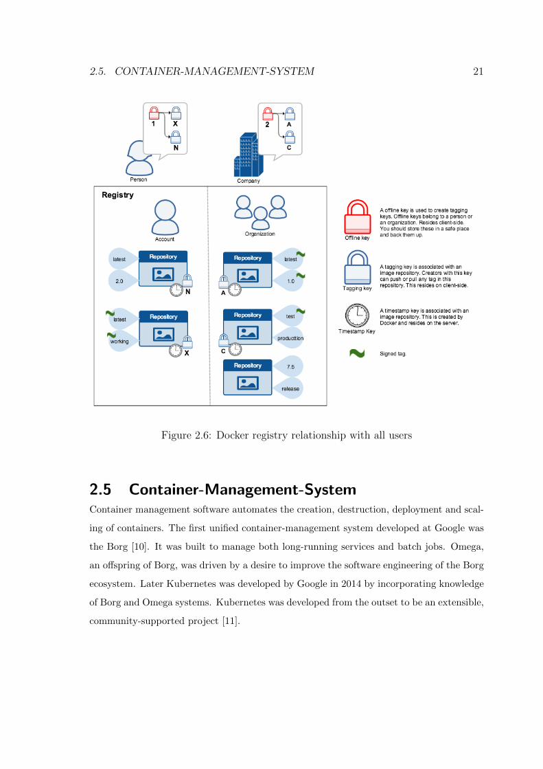
unwanted restarts of containers. Hence Docker Content Trust was introduced [36].As given
in the documentation[37], when transferring data among networked systems, trust is a cen-
tral concern. The figure 2.5 depicts various signing keys and their relationships inside a
docker registry [37].
When communicating over an un-trusted medium such as the internet, it is critical to en-
sure the data integrity and the publisher of the all data on which the system is operating
on. Content trust gives us the ability to verify both the integrity and the publisher of all
the data received from a registry over any channel. Content trust allows operations with
a remote Docker registry to enforce client-side signing and verification of image tags. The
content trust provides the ability to use digital signatures for data sent and received from
remote Docker registries [36]. These signatures allow client-side verification of the integrity
and publisher of specific image tags. To enable it, set the DOCKER CONTENT TRUST
environment variable to 1. Once content trust is enabled, image publishers can sign their
images. Image consumers can ensure that the images they use are signed. Publishers and
consumers can be individuals alone or in organizations. Docker’s content trust supports
users and automated processes such as builds.
2.5. CONTAINER-MANAGEMENT-SYSTEM 21
Figure 2.6: Docker registry relationship with all users
2.5 Container-Management-SystemContainer management software automates the creation, destruction, deployment and scal-
ing of containers. The first unified container-management system developed at Google was
the Borg [10]. It was built to manage both long-running services and batch jobs. Omega,
an offspring of Borg, was driven by a desire to improve the software engineering of the Borg
ecosystem. Later Kubernetes was developed by Google in 2014 by incorporating knowledge
of Borg and Omega systems. Kubernetes was developed from the outset to be an extensible,
community-supported project [11].
22 CHAPTER 2. BACKGROUND
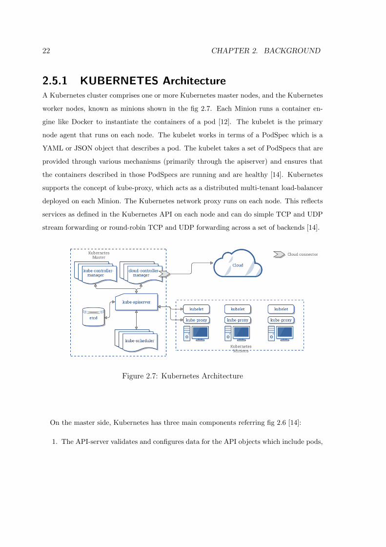
2.5.1 KUBERNETES ArchitectureA Kubernetes cluster comprises one or more Kubernetes master nodes, and the Kubernetes
worker nodes, known as minions shown in the fig 2.7. Each Minion runs a container en-
gine like Docker to instantiate the containers of a pod [12]. The kubelet is the primary
node agent that runs on each node. The kubelet works in terms of a PodSpec which is a
YAML or JSON object that describes a pod. The kubelet takes a set of PodSpecs that are
provided through various mechanisms (primarily through the apiserver) and ensures that
the containers described in those PodSpecs are running and are healthy [14]. Kubernetes
supports the concept of kube-proxy, which acts as a distributed multi-tenant load-balancer
deployed on each Minion. The Kubernetes network proxy runs on each node. This reflects
services as defined in the Kubernetes API on each node and can do simple TCP and UDP
stream forwarding or round-robin TCP and UDP forwarding across a set of backends [14].
Figure 2.7: Kubernetes Architecture
On the master side, Kubernetes has three main components referring fig 2.6 [14]:
1. The API-server validates and configures data for the API objects which include pods,
2.5. CONTAINER-MANAGEMENT-SYSTEM 23
services, replication controllers, and others [14]. It provides frontend to the shared
state through which all other components interact. It also serves the CRUD (create,
read, update, delete) operations on the Kubernetes objects [12].
2. The scheduler is a policy-rich, topology-aware, workload-specific function that sig-
nificantly impacts availability, performance, and capacity. The scheduler needs to
take into account individual and collective resource requirements, quality of service
requirements, hardware/software/policy constraints, affinity and anti-affinity specifi-
cations, data locality, inter-workload interference, deadlines [14].
3. The Kubernetes Controller Manager is a daemon that embeds the core control loops
(also known as ”controllers”) shipped with Kubernetes. Basically, a controller watches
the state of the cluster through the API Server watch feature and, when it gets
notified, it makes the necessary changes attempting to move the current state towards
the desired state [13].
4. Etcd is a distributed, consistent key-value store used for configuration management,
service discovery, and coordinating distributed work.
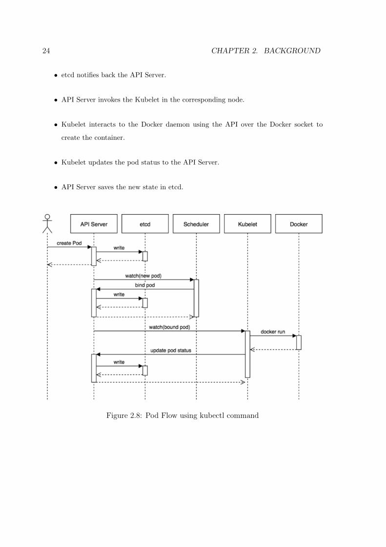
2.5.2 Creating a PODA simple flow diagram(fig 2.8) explaining pod creation inside Kubernetes cluster [13].
• kubectl writes to the API Server.
• API Server validates the request and saves it to etcd.
• etcd notifies back the API server.
• API Server invokes the scheduler.
• Scheduler decides where to run the pod on and returns the decision back to API
server.
• API Server stores it to etcd.
24 CHAPTER 2. BACKGROUND
• etcd notifies back the API Server.
• API Server invokes the Kubelet in the corresponding node.
• Kubelet interacts to the Docker daemon using the API over the Docker socket to
create the container.
• Kubelet updates the pod status to the API Server.
• API Server saves the new state in etcd.
Figure 2.8: Pod Flow using kubectl command
2.5. CONTAINER-MANAGEMENT-SYSTEM 25
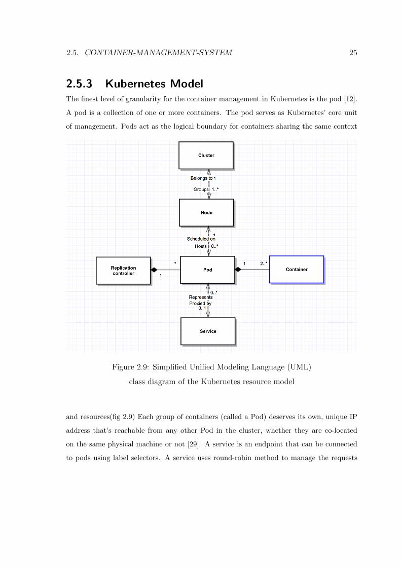
2.5.3 Kubernetes ModelThe finest level of granularity for the container management in Kubernetes is the pod [12].
A pod is a collection of one or more containers. The pod serves as Kubernetes’ core unit
of management. Pods act as the logical boundary for containers sharing the same context
Figure 2.9: Simplified Unified Modeling Language (UML)
class diagram of the Kubernetes resource model
and resources(fig 2.9) Each group of containers (called a Pod) deserves its own, unique IP
address that’s reachable from any other Pod in the cluster, whether they are co-located
on the same physical machine or not [29]. A service is an endpoint that can be connected
to pods using label selectors. A service uses round-robin method to manage the requests
26 CHAPTER 2. BACKGROUND
between pods. Services are the external point of contact for container workloads, accessible
via an internal DNS server [16]. A replication controller ensures that a configurable number
of pod replicas are running at any point in time in the cluster. It is also responsible for
scaling up/down the number of replicas according to a scaling policy. The deletion of the
replication controller entails the deletion of all its pods [12].
2.5.4 Advantages of Kubernetes cluster
Docker providing an open standard for packaging and distributing containerized applications
lead to a new problem. Coordination, scheduling, scaling container instances and commu-
nication between other containers had to be managed by an external service. Orchestrators
for managing containers were introduced. Kubernetes, Mesos, and Docker Swarm are some
of the more popular options for providing an abstraction for a cluster of machines to behave
like one big machine, which is important in a large-scale environment. Kubernetes and
Docker are both comprehensive de-facto solutions to manage containerized applications
wisely and provide powerful capabilities [15]. Few advantages are as follows [17]:
• Kubernetes eliminates infrastructure lock-in by providing core capabilities for contain-
ers without imposing restrictions. It achieves this through a combination of features
within the Kubernetes platform, including Pods and Services.
• Kubernetes service groups together a collection of Pods that perform a similar func-
tion which can be configured for discoverability, observability, horizontal scaling, and
load balancing. This eliminates the problem of communication and sharing of re-
sources between containers by Docker alone.
• It doesn’t restrict application frameworks (such as Wildfly), or the supported language
runtimes (Java, Python, Ruby), or cater to only 12-factor applications, or distinguish
”apps” from ”services”. Kubernetes provides wide latitude for supporting all types
of applications.
2.5. CONTAINER-MANAGEMENT-SYSTEM 27
• Kubernetes marks a breakthrough for DevOps as it allows teams to keep pace with
the requirements of modern software development. It allows the developers to derive
maximum utility from containers and build cloud-native applications that can run
anywhere, independent of cloud-specific requirements by building an efficient model
for application development.
• One of the unique features of Kubernetes is, it provides horizontal auto-scaling, rolling
updates across the pods and supporting canary deployments.
Chapter 3
Implementation
The most important problem faced by software professionals is implementation of new
ideas and delivering the updated software to the end-users as soon as possible. A software
development lifecycle includes building, deploying, testing, and release process. Previously
available deployment strategies treated each phase as a separate atomic unit which resulted
to have more risk of failures. Over time, deployments are converted into a fully automated
pipeline. It consists of two tasks which has to be performed manually. One of the tasks
is to deploy software into a development, test, or production environment by selecting
the version of the software and environment. Another task is to press the deploy button.
Released packaged software involves a single automated process creating the installer. This
is now achieved using Continuous Integration/Continuous Delivery Pipeline (CI/CD).
3.1 Problems in Manual Deployment
Most modern applications are complex to deploy involving separating phases and are re-
leased manually. By this we mean that the steps required to deploy such an application
are treated as separate and atomic, each performed by an individual or team. Decisions
are made within these steps, leaving them prone to human error. In other cases, even the
differences in the ordering and timing of these steps can lead to different outcomes [2]. The
problems faced in manual deployments are:
28
3.2. DEPLOYMENT PIPELINE 29
• The production of extensive, detailed documentation that describes the steps to be
taken and the ways in which the steps may go wrong.
• Reliance on manual testing to confirm that the application is running correctly.
• Frequent calls to the development team to explain why a deployment is going wrong
on a release day.
• Frequent corrections to the release process during the course of a release. Environ-
ments in a cluster differ in their configuration, for example, application servers with
different connection pool settings, file systems with different layouts, etc.
• Releases that take more than a few minutes to perform.
• Releases might be unpredictable in their outcome, often have to be rolled back or run
into unforeseen problems.
3.2 Deployment PipelineA deployment pipeline is an automated implementation of the application’s build, deploy,
test, and release process. Every organization will implement different pipeline techniques
depending on their value stream for releasing software, but the main principle remains the
same. A simple structure of Deployment Pipeline is shown in the fig 3.1. Every change that
is made to an application’s configuration, source code, environment, or data, triggers the
creation of a new instance of the pipeline. Initialization involves the creation of binaries
and installers. The rest of the pipeline runs a series of tests on the binaries to release
into production. The deployment pipeline has its foundations in the process of continuous
integration[2]. The aim of the deployment pipeline is threefold. First, it makes every part
of the process of building, deploying, testing, and releasing software visible to everyone, and
aiding collaboration. Second, it improves feedback so that problems are identified, and are
resolved, as early as possible. Finally, it enables teams to deploy and release any version
of their software to any environment through a fully automated process. A simple example
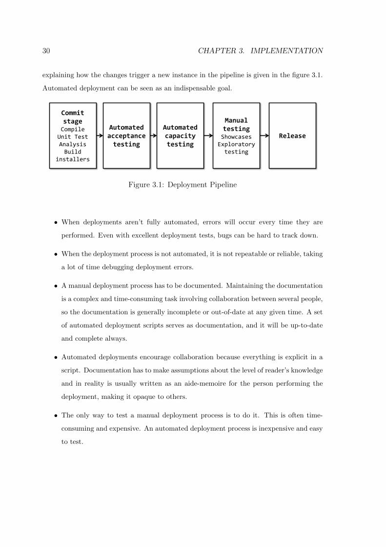
30 CHAPTER 3. IMPLEMENTATION
explaining how the changes trigger a new instance in the pipeline is given in the figure 3.1.
Automated deployment can be seen as an indispensable goal.
Automated acceptance testing
Commit stage Compile Unit Test Analysis Build
installers
Automated capacity testing
Manual testing Showcases Exploratory testing
Release
Figure 3.1: Deployment Pipeline
• When deployments aren’t fully automated, errors will occur every time they are
performed. Even with excellent deployment tests, bugs can be hard to track down.
• When the deployment process is not automated, it is not repeatable or reliable, taking
a lot of time debugging deployment errors.
• A manual deployment process has to be documented. Maintaining the documentation
is a complex and time-consuming task involving collaboration between several people,
so the documentation is generally incomplete or out-of-date at any given time. A set
of automated deployment scripts serves as documentation, and it will be up-to-date
and complete always.
• Automated deployments encourage collaboration because everything is explicit in a
script. Documentation has to make assumptions about the level of reader’s knowledge
and in reality is usually written as an aide-memoire for the person performing the
deployment, making it opaque to others.
• The only way to test a manual deployment process is to do it. This is often time-
consuming and expensive. An automated deployment process is inexpensive and easy
to test.
3.3. CI/CD PIPELINE 31
• With a manual processing, there is no guarantee that the documentation has been
followed. the automated process is easy to follow and is fully auditable[2].
3.3 CI/CD Pipeline
Continuous integration (CI) is the process of integrating the code into a shared repository
as frequently as possible. During code integration, a build break or a test failure can inform
in a timely manner about an error in the code. When many developers collaborate on
complex software projects, it can be a long and unpredictable process to integrate different
parts of code together. However, this process can be made more efficient and more reliable
by building and deploying the project continuously. There are three things needed before
beginning with continuous integration.
• Version Control: Everything in the project must be checked into a single version
control repository: code, tests, database scripts, build and deployment scripts, and
anything else needed to create, install, run, and test the application. There exist
several simple, powerful, lightweight, and free version control systems. VSTS provides
flexible and extensible version control supporting the use of Git for distributed version
control or Team Foundation Version Control (TFVC) for centralized version control
[18].
• Automated Build: We need to have a command-line program that tells our IDE to
build the software and then runs series of tests, or it can be a complex collection of
multistage build scripts that call one another. These build scripts need to run in an
automated way from the command line.
• Agreement of the Team: Continuous integration is a practice, not a tool. It requires
a degree of commitment and discipline development team. Checking-in small incre-
mental changes frequently to mainline and agree that the highest priority task on the
project is to fix any change that breaks the application.
32 CHAPTER 3. IMPLEMENTATION
VSTS simplifies Continuous Integration for our applications regardless of the platform
being targeted, or the language being used. VSTS Team Build allows to:
• Build on Linux, Mac, and Windows
• Use a private or a hosted (Azure) build agent
• Use multi-platform build agents for Android, ioperating system, Java, .NET, and
other applications
• Seamless integration with work, test, code, build and release
• Track the builds with real-time build status.
Continuous Delivery (CD) is a lean practice that aims to eliminate diverging code, du-
plication of effort and, most importantly merging conflicts. It starts with CI- the process
of automating the build and testing of code every time anyone commits a change to version
control. When a developer implements a new feature or bug fix in a feature branch, we
submit a pull request when the feature is complete. Upon approval of the pull request,
changes are committed and merged into the master branch. CD is the process to build,
test, configure, deploy and confirm a feature change to production. To deliver value to
users, it’s important to achieve the shortest path to deploy a new feature (known as time to
mitigate, or TTM) and to minimize reaction time to feedback (known as time to remediate,
or TTR). The goal is to achieve an automated and reliable deployment process that con-
sistently confirms through integration, load and user acceptance testing, and continuously
releases value to the end users. CD promises to banish manual processes, time-consuming
and error-prone handoffs, and unreliable releases that produce delays, cost overruns, and
also avoids end-user dissatisfaction. A release pipeline is a collection of environments and
workflows to support the activities of CI and CD.
3.4. BUILD AND RELEASE PIPELINE 33
3.4 Build and Release pipeline
For simple projects, building and testing of software can be accomplished using the capa-
bilities of our IDE (Integrated Development Environment). As soon as the project extends
beyond a single person, spans more than a few days, or produces more than a single ex-
ecutable file as its output, it demands more control. It is also vital to script building,
testing, and packaging applications when working on large or distributed teams (including
open source projects). The first step is to select the platform to run the build from the com-
mand line. Rail projects can run the default Rake task; .NET projects can use MSBuild;
Java projects (if set up correctly) can use Ant, Maven, or Gradle; and with SCons, not
much is required to get a simple C/C++ project going [2]. This makes it straightforward
to begin continuous integration and CI server run this command to create binaries. .NET
and C/C++ users need to copy dependencies to run the program successfully.
Automating deployment introduces complexities. In most cases, it requires a series of
steps such as configuring the application, initializing data, configuring the infrastructure,
operating systems, and middleware, setting up mock external systems, and so on. As
projects get more complex, these steps become more numerous, longer, and (if they are
not automated) more error-prone. Azure Container Service (ACS) allows deploying and
managing containers using Docker Swarm, Mesosphere DC/operating system or Kubernetes
orchestrators. With the recent release of open-source ACS-engine, it is now very easy to
deploy these three orchestrators on Azure, using the portal, an Azure Resource Manager
template or Azure-CLI. They also have released it in preview version. The Azure Container
Registry which is an implementation of the open source Docker Registry and that can
run as a service on Azure and is fully compatible with Docker Swarm, Kubernetes and
DC/operating system. This is a private registry that allows storage Docker images for
enterprise applications instead of having to use the public Docker Hub, for example. A
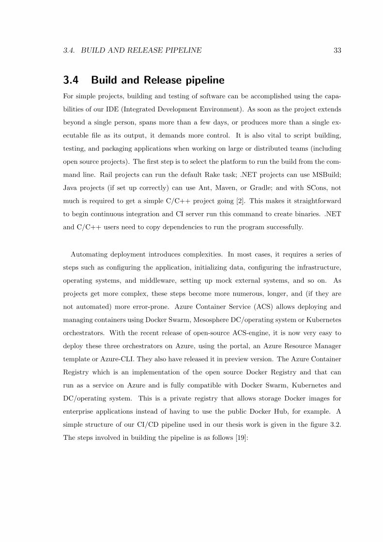
simple structure of our CI/CD pipeline used in our thesis work is given in the figure 3.2.
The steps involved in building the pipeline is as follows [19]:
34 CHAPTER 3. IMPLEMENTATION
Figure 3.2: CI/CD Pipeline
• Developing new features using Visual Studio Code (or any IDE) and commits changes
on to the GitHub.
• GitHub triggers a build in VSTS.
• VSTS gets the latest version of the sources and build all the images that compose the
application.
• VSTS pushes each image in the Azure Container Registry.
• VSTS triggers a new release.
• The release runs some commands using SSH on the ACS cluster master node.
• Docker or Docker Swarm on ACS pulls the latest version of the image from Azure
Container Registry and the application is deployed using Kubernetes.
3.4. BUILD AND RELEASE PIPELINE 35
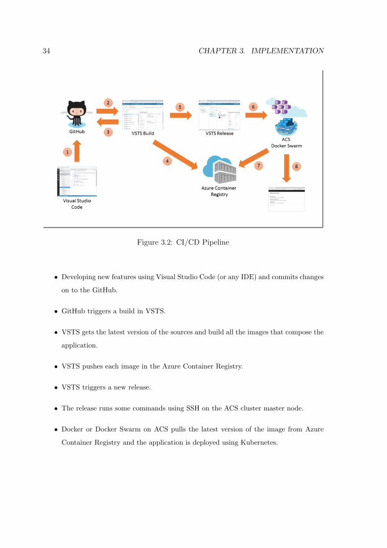
3.4.1 CI/CD Process Definition
A continuous integration (CI) process automatically builds and tests code every time a team
member commits changes to version control. A simple build CI definition dotnet2kube-CI
is created by executing set of tasks to build the .NET Core application. An example of
build pipeline can be seen in the figure 3.3. The set tasks are as follows:
• Restore: Restores the dependencies and tools of a project.
• Build: Compiling the project using the solution file.
• Publish & Publish iTest: Publishing test results from all the files will be reported
against a single test run.
• Build, push Image with Docker: Building the Dockerfile and pushing the image to
Azure Container Registry.
Figure 3.3: Build definiton
36 CHAPTER 3. IMPLEMENTATION
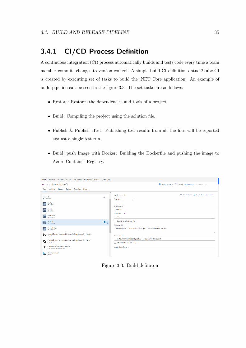
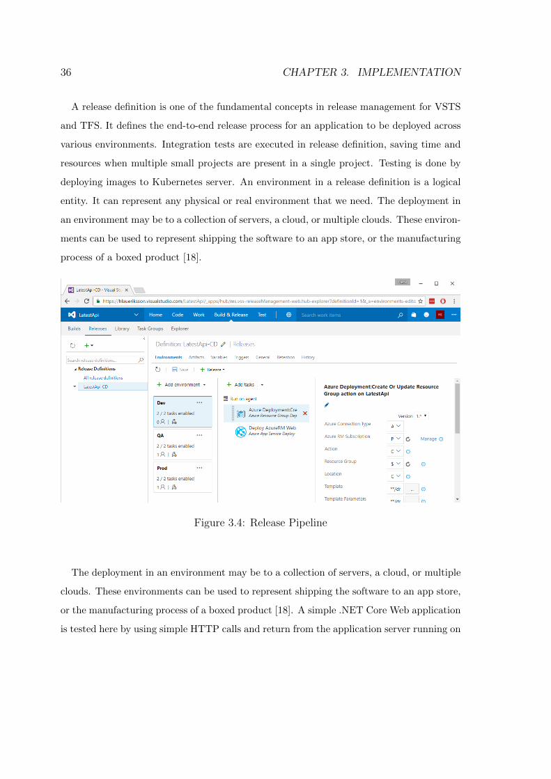
A release definition is one of the fundamental concepts in release management for VSTS
and TFS. It defines the end-to-end release process for an application to be deployed across
various environments. Integration tests are executed in release definition, saving time and
resources when multiple small projects are present in a single project. Testing is done by
deploying images to Kubernetes server. An environment in a release definition is a logical
entity. It can represent any physical or real environment that we need. The deployment in
an environment may be to a collection of servers, a cloud, or multiple clouds. These environ-
ments can be used to represent shipping the software to an app store, or the manufacturing
process of a boxed product [18].
Figure 3.4: Release Pipeline
The deployment in an environment may be to a collection of servers, a cloud, or multiple
clouds. These environments can be used to represent shipping the software to an app store,
or the manufacturing process of a boxed product [18]. A simple .NET Core Web application
is tested here by using simple HTTP calls and return from the application server running on
3.4. BUILD AND RELEASE PIPELINE 37
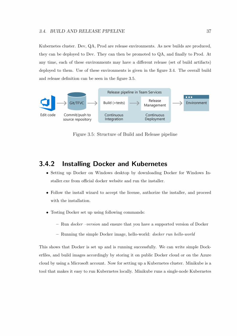
Kubernetes cluster. Dev, QA, Prod are release environments. As new builds are produced,
they can be deployed to Dev. They can then be promoted to QA, and finally to Prod. At
any time, each of these environments may have a different release (set of build artifacts)
deployed to them. Use of these environments is given in the figure 3.4. The overall build
and release definition can be seen in the figure 3.5.
Figure 3.5: Structure of Build and Release pipeline
3.4.2 Installing Docker and Kubernetes• Setting up Docker on Windows desktop by downloading Docker for Windows In-
staller.exe from official docker website and run the installer.
• Follow the install wizard to accept the license, authorize the installer, and proceed
with the installation.
• Testing Docker set up using following commands:
– Run docker –version and ensure that you have a supported version of Docker
– Running the simple Docker image, hello-world: docker run hello-world
This shows that Docker is set up and is running successfully. We can write simple Dock-
erfiles, and build images accordingly by storing it on public Docker cloud or on the Azure
cloud by using a Microsoft account. Now for setting up a Kubernetes cluster. Minikube is a
tool that makes it easy to run Kubernetes locally. Minikube runs a single-node Kubernetes
38 CHAPTER 3. IMPLEMENTATION
cluster inside a VM running on our laptop for users. Before trying to install Minikube, we
need a VirtualBox up and running for Windows OS or on Linux OS. We need to install a
kubernetes command-line tool kubectl, to deploy and manage applications on Kubernetes.
Using kubectl, we can inspect cluster resources; create, delete, and update components.
• Using Chocolatey package manager on Windows we can install kubernetes-cli directly
choco install kubernetes-cli // installs command line-tool
Kubectl version // outputs the version of Kubernetes in use
• Configure kubectl to use a remote Kubernetes cluster by setting environment variables
to the corresponding config file:
Kubectl config-view // returns the cluster information
If successfully installed, we can create new deployment pods, services on the cluster.
Here the number of nodes is restricted to our VM running on the PC, which drains up the
battery and uses up the RAM capacity which leads to less performance. To get additional
resources, increase performance we can use. The Azure Container Service that offers simple
deployments of one of three open source orchestrators: DC/operating system, Swarm, and
Kubernetes clusters. ACS-Engine is a good choice if we need to make customizations to
the deployment beyond what the Azure Container Service officially supports. These cus-
tomizations include deploying into existing virtual networks, utilizing multiple agent pools,
and more. Some community contributions to ACS-Engine may even become features of the
Azure Container Service. AKS reduces the complexity and operational overhead of man-
aging a Kubernetes cluster by offloading much of that responsibility to Azure. As a hosted
Kubernetes service, Azure handles critical tasks like health monitoring and maintenance.
We need to pay only for the agent nodes within our clusters, not for the masters. As a
managed Kubernetes service, AKS provides:
• Automated Kubernetes version upgrades and patching
• Easy cluster scaling
3.5. WALBERLA FRAMEWORK 39
• Self-healing hosted control plane (masters)
• Cost savings - pay only for running agent pool nodes
With Azure handling the management of the nodes in the AKS cluster, we no longer
need to perform tasks manually, like cluster upgrades. Because Azure handles these critical
maintenance tasks, AKS does not provide direct access (such as with SSH) to the cluster.
We can deploy Kubernetes cluster directly via an Azure portal or use a command line
interface. We can install az-cli locally same as kubectl command-line tool. Using az-cli:
• az group create –name myResourceGroup –location eastus
This creates a resource group named myResourceGroup in the eastus location. An
Azure resource group is a logical group in which Azure resources are deployed and
managed. When creating a resource group we are asked to specify a location, this is
where our resources will live in Azure.
• az aks create –resource-group myResourceGroup –name myAKSCluster –node-count
1 –generate-ssh-keys
This creates a cluster named myAKSCluster with one node. Once the cluster is
created, we can access it locally by getting credentials with respect to new cluster
created. Now Azure Container Service (AKS) makes it simple to create, configure,
and manage a cluster of virtual machines that are preconfigured to run containerized
applications.
3.5 WALBERLA FrameworkA C++ software framework waLBerla [9], a code for simulations based on the lattice Boltz-
mann method (LBM). The waLBerla framework employs a block-structured partitioning
of the simulation space: Initially, the simulation domain is subdivided into equally sized
blocks. The domain can have any arbitrary shape. Each initial block can be further sub-
divided into eight equally sized, smaller blocks. Within each block, a uniform grid of cells
40 CHAPTER 3. IMPLEMENTATION
is constructed. The grids contained within two different blocks can have different cell sizes,
meaning different blocks can possess different grid resolutions. This allows domain parti-
tionings ranging from cartesian grids that are uniformly split into blocks to octree-like block
structures with all blocks containing the same number of cells, thereby forming meshes that
resemble grid structures typically associated with grid refinement. A uniform grid bench-
mark code is used to measure the performance of Kubernetes cluster. For MPI parallel
simulations, these blocks are distributed among all available processes. Depending on the
initial, static load balancing strategy, none, one, or multiple blocks can be assigned to one
process.
Master Pod sshd container
Slave Pod sshd container
Slave Pod sshd container
Slave Pod sshd container
Port 22
KUBERNETES Cluster
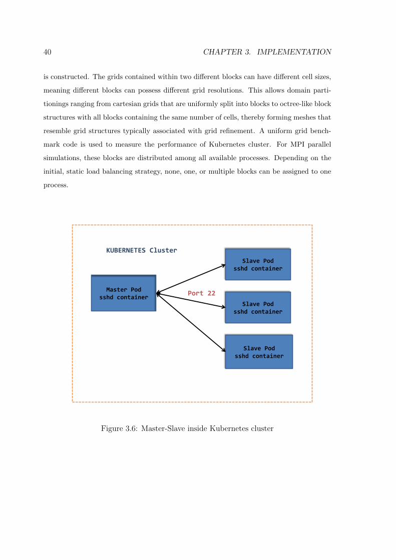
Figure 3.6: Master-Slave inside Kubernetes cluster
3.5. WALBERLA FRAMEWORK 41
For LBM simulations, the regular grid within each block is extended by one additional
ghost layer of cells which is used in every time step during communication in order to
synchronize the cell data on the boundary between neighboring blocks. The data structure
holding this block structure is fully distributed: Each process only knows about its own
blocks and blocks assigned to neighboring processes. Each process only allocates grid and
cell data for those blocks assigned to it. Generally, processes have no knowledge about
blocks that are not located in their immediate process neighborhood. As a consequence,
the memory usage of a particular process only depends on the number of blocks assigned
to this process, and not on the size of the entire simulation, i.e., the total number of blocks
assigned to all available processes.
The benchmark code is compiled using the basic image ubuntu 16.07 in the Dockerfile.
To reduce the size of docker image, multi-stage builds are used and is implemented as
shown in the APPENDIX A. Each container images run sshd container which is required
for MPI communication. Loading these images to the pod on Kubernetes cluster. The
master pod (APPENDIX B) starts the program and communicates with the worker pod
using ssh protocol on port 22. Each process needs 3 GB of memory. The tests are run by
varying the number of processes and results are calculated. Once the run is complete, the
output is stored on the master pod. The results are evaluated against roofline model and
concluded based on results. The implementation can be seen in the fig 3.6
Chapter 4
Testing
.NET Core application using CI/CD build pipeline is tested against different types of Ku-
bernetes cluster. On the same Kubernetes cluster, benchmark docker images are used to
measure the performance of the cluster (APPENDIX A). Azure Container Service (AKS)
cluster can be built with virtual-kubelet and without a virtual-kubelet node depending
on usage and implementation. The results are verified by constructing a roofline model
(APPENDIX B).
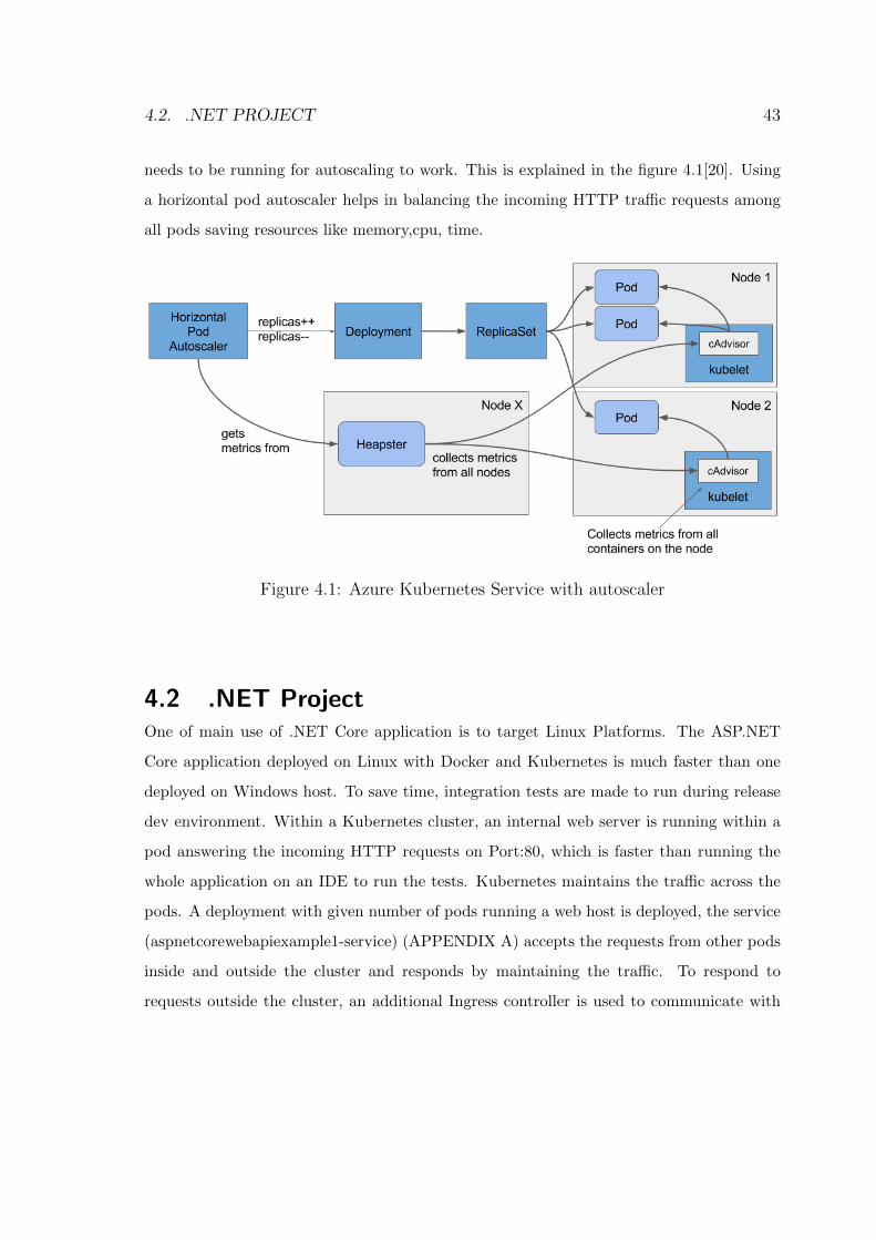
4.1 AKS cluster (single node VM, 7GB memory)One of the basic Kubernetes features is the ability to manually scale pods up or down
horizontally simply by increasing or decreasing the desired replica count field on the De-
ployment, Replica Set (RS) or Replication Controller (RC). Automatic scaling is built on
top of that. To make Kubernetes scale the pods automatically, all we need to do is create a
Horizontal Pod Autoscaler (HPA) object. In the case of CPU-utilization-based autoscaling,
the controller will then start observing the CPU usage of the pods and scale the Deploy-
ment/RC so the average CPU utilization across all of the pods is kept close to the target
CPU utilization configured in the HPA object. The CPU usage (and other metrics) is col-
lected by cAdvisor, which runs inside the kubelet. All those metrics are then aggregated
by Heapster, which runs as a single pod (on one of the nodes) and collects metrics from
all nodes in the cluster. The autoscaler controller gets the metrics from Heapster, so it
42
4.2. .NET PROJECT 43
needs to be running for autoscaling to work. This is explained in the figure 4.1[20]. Using
a horizontal pod autoscaler helps in balancing the incoming HTTP traffic requests among
all pods saving resources like memory,cpu, time.
Figure 4.1: Azure Kubernetes Service with autoscaler
4.2 .NET ProjectOne of main use of .NET Core application is to target Linux Platforms. The ASP.NET
Core application deployed on Linux with Docker and Kubernetes is much faster than one
deployed on Windows host. To save time, integration tests are made to run during release
dev environment. Within a Kubernetes cluster, an internal web server is running within a
pod answering the incoming HTTP requests on Port:80, which is faster than running the
whole application on an IDE to run the tests. Kubernetes maintains the traffic across the
pods. A deployment with given number of pods running a web host is deployed, the service
(aspnetcorewebapiexample1-service) (APPENDIX A) accepts the requests from other pods
inside and outside the cluster and responds by maintaining the traffic. To respond to
requests outside the cluster, an additional Ingress controller is used to communicate with
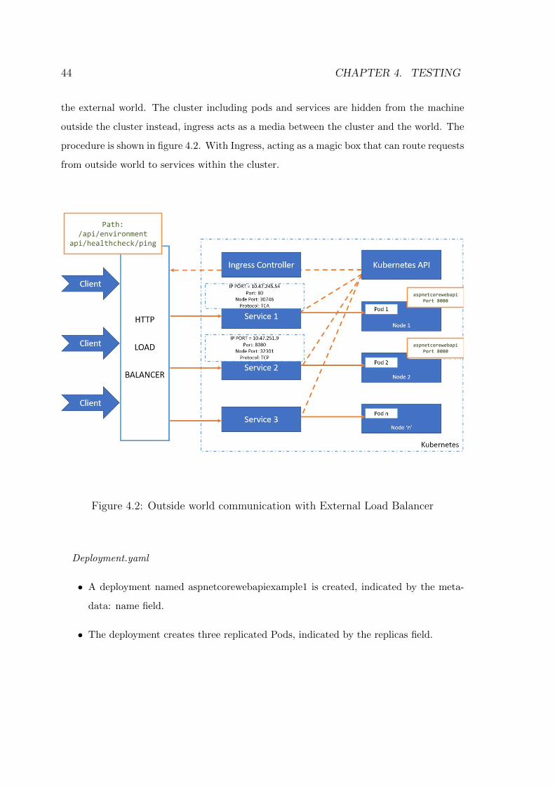
44 CHAPTER 4. TESTING
the external world. The cluster including pods and services are hidden from the machine
outside the cluster instead, ingress acts as a media between the cluster and the world. The
procedure is shown in figure 4.2. With Ingress, acting as a magic box that can route requests
from outside world to services within the cluster.
aspnetcorewebapi Port 8080
aspnetcorewebapi Port 8080
Path: /api/environment
api/healthcheck/ping
Figure 4.2: Outside world communication with External Load Balancer
Deployment.yaml
• A deployment named aspnetcorewebapiexample1 is created, indicated by the meta-
data: name field.
• The deployment creates three replicated Pods, indicated by the replicas field.
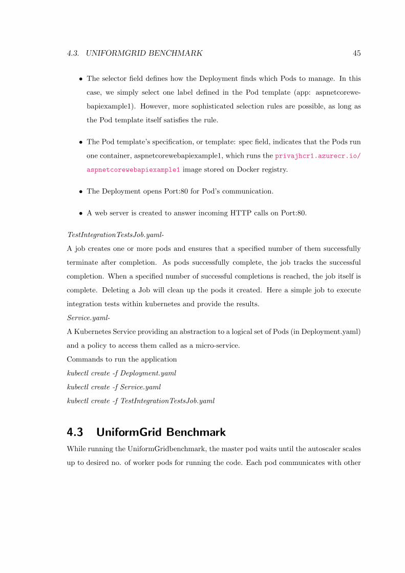
4.3. UNIFORMGRID BENCHMARK 45
• The selector field defines how the Deployment finds which Pods to manage. In this
case, we simply select one label defined in the Pod template (app: aspnetcorewe-
bapiexample1). However, more sophisticated selection rules are possible, as long as
the Pod template itself satisfies the rule.
• The Pod template’s specification, or template: spec field, indicates that the Pods run
one container, aspnetcorewebapiexample1, which runs the privajhcr1.azurecr.io/
aspnetcorewebapiexample1 image stored on Docker registry.
• The Deployment opens Port:80 for Pod’s communication.
• A web server is created to answer incoming HTTP calls on Port:80.
TestIntegrationTestsJob.yaml-
A job creates one or more pods and ensures that a specified number of them successfully
terminate after completion. As pods successfully complete, the job tracks the successful
completion. When a specified number of successful completions is reached, the job itself is
complete. Deleting a Job will clean up the pods it created. Here a simple job to execute
integration tests within kubernetes and provide the results.
Service.yaml-
A Kubernetes Service providing an abstraction to a logical set of Pods (in Deployment.yaml)
and a policy to access them called as a micro-service.
Commands to run the application
kubectl create -f Deployment.yaml
kubectl create -f Service.yaml
kubectl create -f TestIntegrationTestsJob.yaml
4.3 UniformGrid Benchmark
While running the UniformGridbenchmark, the master pod waits until the autoscaler scales
up to desired no. of worker pods for running the code. Each pod communicates with other
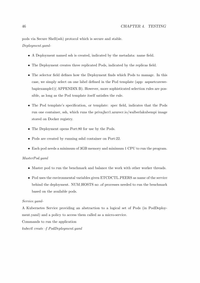
46 CHAPTER 4. TESTING
pods via Secure Shell(ssh) protocol which is secure and stable.
Deployment.yaml-
• A Deployment named ssh is created, indicated by the metadata: name field.
• The Deployment creates three replicated Pods, indicated by the replicas field.
• The selector field defines how the Deployment finds which Pods to manage. In this
case, we simply select on one label defined in the Pod template (app: aspnetcorewe-
bapiexample1)( APPENDIX B). However, more sophisticated selection rules are pos-
sible, as long as the Pod template itself satisfies the rule.
• The Pod template’s specification, or template: spec field, indicates that the Pods
run one container, ssh, which runs the privajhcr1.azurecr.io/walberlakubempi image
stored on Docker registry.
• The Deployment opens Port:80 for use by the Pods.
• Pods are created by running sshd container on Port:22.
• Each pod needs a minimum of 3GB memory and minimum 1 CPU to run the program.
MasterPod.yaml
• Master pod to run the benchmark and balance the work with other worker threads.
• Pod uses the environmental variables given ETCDCTL PEERS as name of the service
behind the deployment. NUM HOSTS no .of processes needed to run the benchmark
based on the available pods.
Service.yaml-
A Kubernetes Service providing an abstraction to a logical set of Pods (in PodDeploy-
ment.yaml) and a policy to access them called as a micro-service.
Commands to run the application
kubectl create -f PodDeployment.yaml
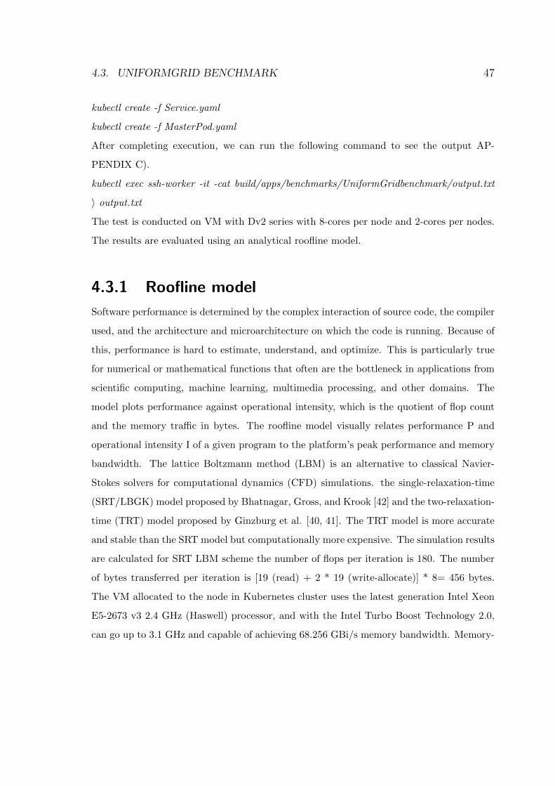
4.3. UNIFORMGRID BENCHMARK 47
kubectl create -f Service.yaml
kubectl create -f MasterPod.yaml
After completing execution, we can run the following command to see the output AP-
PENDIX C).
kubectl exec ssh-worker -it -cat build/apps/benchmarks/UniformGridbenchmark/output.txt
〉 output.txt
The test is conducted on VM with Dv2 series with 8-cores per node and 2-cores per nodes.
The results are evaluated using an analytical roofline model.
4.3.1 Roofline model
Software performance is determined by the complex interaction of source code, the compiler
used, and the architecture and microarchitecture on which the code is running. Because of
this, performance is hard to estimate, understand, and optimize. This is particularly true
for numerical or mathematical functions that often are the bottleneck in applications from
scientific computing, machine learning, multimedia processing, and other domains. The
model plots performance against operational intensity, which is the quotient of flop count
and the memory traffic in bytes. The roofline model visually relates performance P and
operational intensity I of a given program to the platform’s peak performance and memory
bandwidth. The lattice Boltzmann method (LBM) is an alternative to classical Navier-
Stokes solvers for computational dynamics (CFD) simulations. the single-relaxation-time
(SRT/LBGK) model proposed by Bhatnagar, Gross, and Krook [42] and the two-relaxation-
time (TRT) model proposed by Ginzburg et al. [40, 41]. The TRT model is more accurate
and stable than the SRT model but computationally more expensive. The simulation results
are calculated for SRT LBM scheme the number of flops per iteration is 180. The number
of bytes transferred per iteration is [19 (read) + 2 * 19 (write-allocate)] * 8= 456 bytes.
The VM allocated to the node in Kubernetes cluster uses the latest generation Intel Xeon
E5-2673 v3 2.4 GHz (Haswell) processor, and with the Intel Turbo Boost Technology 2.0,
can go up to 3.1 GHz and capable of achieving 68.256 GBi/s memory bandwidth. Memory-
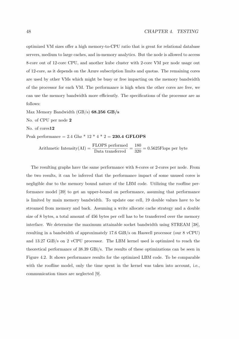
48 CHAPTER 4. TESTING
optimized VM sizes offer a high memory-to-CPU ratio that is great for relational database
servers, medium to large caches, and in-memory analytics. But the node is allowed to access
8-core out of 12-core CPU, and another kube cluster with 2-core VM per node usage out
of 12-core, as it depends on the Azure subscription limits and quotas. The remaining cores
are used by other VMs which might be busy or free impacting on the memory bandwidth
of the processor for each VM. The performance is high when the other cores are free, we
can use the memory bandwidth more efficiently. The specifications of the processor are as
follows:
Max Memory Bandwidth (GB/s) 68.256 GB/s
No. of CPU per node 2
No. of cores12
Peak performance = 2.4 Ghz * 12 * 4 * 2 = 230.4 GFLOPS
Arithmetic Intensity(AI) =FLOPS performed
Data transferred=
180
320= 0.5625Flops per byte
The resulting graphs have the same performance with 8-cores or 2-cores per node. From
the two results, it can be inferred that the performance impact of some unused cores is
negligible due to the memory bound nature of the LBM code. Utilizing the roofline per-
formance model [39] to get an upper-bound on performance, assuming that performance
is limited by main memory bandwidth. To update one cell, 19 double values have to be
streamed from memory and back. Assuming a write allocate cache strategy and a double
size of 8 bytes, a total amount of 456 bytes per cell has to be transferred over the memory
interface. We determine the maximum attainable socket bandwidth using STREAM [38],
resulting in a bandwidth of approximately 17.6 GiB/s on Haswell processor (our 8 vCPU)
and 13.27 GiB/s on 2 vCPU processor. The LBM kernel used is optimized to reach the
theoretical performance of 38.39 GBi/s. The results of these optimizations can be seen in
Figure 4.2. It shows performance results for the optimized LBM code. To be comparable
with the roofline model, only the time spent in the kernel was taken into account, i.e.,
communication times are neglected [9].
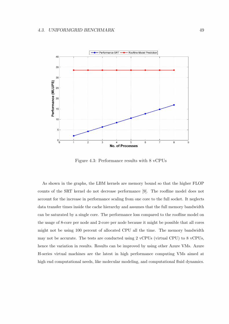
4.3. UNIFORMGRID BENCHMARK 49
Figure 4.3: Performance results with 8 vCPUs
As shown in the graphs, the LBM kernels are memory bound so that the higher FLOP
counts of the SRT kernel do not decrease performance [9]. The roofline model does not
account for the increase in performance scaling from one core to the full socket. It neglects
data transfer times inside the cache hierarchy and assumes that the full memory bandwidth
can be saturated by a single core. The performance loss compared to the roofline model on
the usage of 8-core per node and 2-core per node because it might be possible that all cores
might not be using 100 percent of allocated CPU all the time. The memory bandwidth
may not be accurate. The tests are conducted using 2 vCPUs (virtual CPU) to 8 vCPUs,
hence the variation in results. Results can be improved by using other Azure VMs. Azure
H-series virtual machines are the latest in high performance computing VMs aimed at
high end computational needs, like molecular modeling, and computational fluid dynamics.
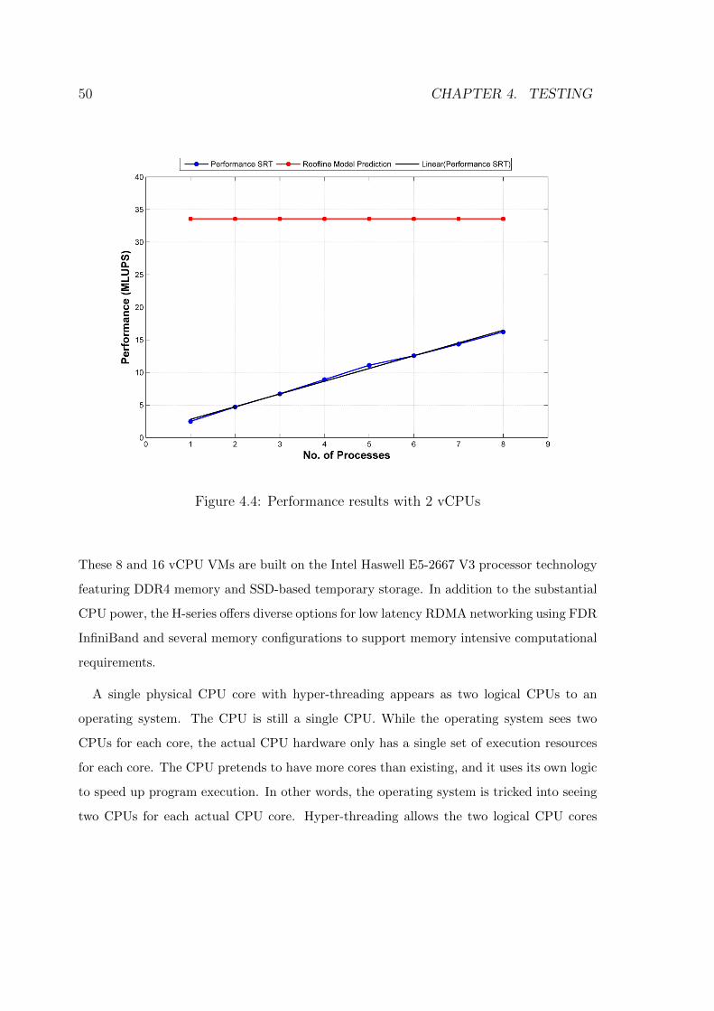
50 CHAPTER 4. TESTING
Figure 4.4: Performance results with 2 vCPUs
These 8 and 16 vCPU VMs are built on the Intel Haswell E5-2667 V3 processor technology
featuring DDR4 memory and SSD-based temporary storage. In addition to the substantial
CPU power, the H-series offers diverse options for low latency RDMA networking using FDR
InfiniBand and several memory configurations to support memory intensive computational
requirements.
A single physical CPU core with hyper-threading appears as two logical CPUs to an
operating system. The CPU is still a single CPU. While the operating system sees two
CPUs for each core, the actual CPU hardware only has a single set of execution resources
for each core. The CPU pretends to have more cores than existing, and it uses its own logic
to speed up program execution. In other words, the operating system is tricked into seeing
two CPUs for each actual CPU core. Hyper-threading allows the two logical CPU cores
4.3. UNIFORMGRID BENCHMARK 51
to share physical execution resources. If one virtual CPU is stalled and waiting, the other
virtual CPU can borrow its execution resources.[44]. Cloud-infrastructure performance is
a key consideration that should not be overlooked. Differences in performance outputs of
VMs across IaaS providers and their variety of product offerings can greatly impact quality
of service (QoS) as well as total cost of ownership (TCO). Selecting the wrong product
or provider to house an application can result in unnecessary overspending and potential
application performance problems [45].
For I/O-intensive workloads, container images can be much more optimal than running
against shared storage (even when the container image exists on that remote storage). That
is normal, as this is the same principle as cache or even the HPC scratch, to have data close
to the process [43] . Even the term CI/CD didn’t originate in HPC, some admins face the
same challenge as their DevOps colleagues, needing to deploy new functionality quickly and
reliably. From linear algebra to differential equation routines, to explicit parallel solvers
used in vehicle crash simulation, that form the core of innovation in the industry verticals
they are used in and are thus mandatory parts of enterprise HPC architectures. Among
these patterns are interactive jobs, MPI parallel jobs, multi-step workflows, and parametric
sweeps. Particularly in enterprise HPC environments, where time is money, users rely on
features like hierarchical resource sharing, topology-aware scheduling, backfill scheduling,
and policy-based pre-emption to get the most out of balancing utilization of expensive
resources with business priorities that may reduce throughput. As enterprise HPC users
experiment with new cloud-native software, existing applications need to be integrated.
Two distinctive approaches have been suggested [21]:
• The first approach is to run containerized and non-containerized workloads on ex-
isting HPC clusters. HPC workload managers increasingly support containerized
applications while preserving the HPC-oriented scheduling semantics. This approach
supports containers but does not support the software services required by native
Kubernetes applications.
52 CHAPTER 4. TESTING
• A second approach is to devise ways of running HPC workloads on local or cloud-
resident Kubernetes clusters. While less common and more cutting-edge, this solution
is now viable and leads to developing greater applications.
A good example of a site using the second, multi-tenant strategy is the Institute for
Health Metrics and Evaluation (IHME), a leading, independent health research center at the
University of Washington that houses the world’s largest population health data repository.
IHME operates a significant HPC environment for various statistical modeling applications
and has also embraced Kubernetes for micro-service applications [21].
Chapter 5
Conclusion
Based on the results obtained, a computational fluid dynamics (CFD) problem may execute
in parallel across many hundreds or even thousands of nodes using a message passing library
to synchronize state. Packaging logic in a container to make it portable, insulated from
environmental dependencies, and easily exchanged with other containers clearly has value.
It is still new to HPC users to pack a workload into a Docker container, publish it to a
registry and submit a YAML description of workload to an orchestrator like Kubernetes.
For running traditional HPC workloads, we can use job submission mechanisms to launch
jobs to instantiate Docker containers on one or more target hosts introducing containerized
workloads with minimal disruption to their environment. There are many HPC workload
managers in the market supporting this.
With AKS preview available, we can run tests on the new AKS cluster and verify the
simulations results and improve the performance and obtain a better deployment pipeline.
.NET Core web applications will be popular in future targeting Linux platforms and are
very useful to build a web application to mobile applications with cross-platform capability
saving time, cost and also speeding up the production. Virtual-kubelet introduced as a new
Azure Instance Container being a serverless container runtime that provides per-second
billing and with no virtual machine management. New features and applications can be
explored using virtual-kubelet on AKS cluster.
53
54 CHAPTER 5. CONCLUSION
A Continuous Delivery pipeline using containerized environments is unsuccessful unless
it’s integrated with the plethora of tools and software stacks to provide end-to-end deliv-
ery of software. Although continuous integrations (CI) is mature in many organizations,
continuous deployment (CD) is not. This process enables greater collaboration between
those involved in delivering software, provides fast feedback so that bugs and unnecessary
or poorly implemented features can be discovered quickly, and paves the route to reducing
that vital metric, cycle time. This, in turn, means faster delivery of valuable, high-quality
software, which leads to higher profitability with lower risk [2]. Finally the demonstration
done in the thesis work on continuous delivery, combined with an automated process for
building, deploying, testing, and releasing software embodied in the deployment pipeline,
is not only compatible with the goals of conformance and performance, but is the most
effective way of enabling a constant flow of software updates into production to quicken
release cycles, lower costs, and reduce the risks associated with development.
Bibliography
[1] Giovanni Toffetti, Sandro Brunner, Martin Blchlinger,Florian Dudouet, and Andrew
Edmonds. An architecture for self-managing microservices. ACM 978-1-4503-3476-1,
2015.
[2] Jez Humble and David Farley. Continuous Delivery. ISBN 978-0-321-60191-9.
[3] B. Kepes. VoltDB Puts the Boot into Amazon Web Services, Claims IBM Is
Five Times Faster. www.forbes.com/sites/benkepes/2014/08/06/voltdb-puts-
the-boot-into-amazon-web-services-claims-ibm-5-faster
[4] C. Mcluckie. Containers, VM’s, Kubernetes and VMware. 25 Aug. 2014
http://googlecloudplatform.blogspot.com/2014/08/containers-VM’s-
kubernetes-and-vmware.html
[5] Knuth: Content Trust in Docker,Docker User Guide, 2016. https://docs.docker.com/
engine/security/trust/content_trust
[6] Victor Marmol, Rohit Jnagal, and Tim Hockin. Networking in Containers and Container
Clusters. Google, Inc. Mountain View, CA USA, accessed Feb 14-15, 2015
[7] Rabindra K. Barik , Rakesh K. Lenka , K. Rahul Rao , Devam Ghose . Performance
analysis of virtual machines and containers in cloud computing. ISBN 978-1-5090-1666-
2, January 2017
55
56 BIBLIOGRAPHY
[8] Wes Felter, Alexandre Ferreira, Ram Rajamony, Juan Rubio. An Updated Performance
Comparison of Virtual Machines and Linux Containers. RC25482 (AUS1407-001) July
21, 2014
[9] Christian Godenschwager, Florian Schornbaum , Martin Bauer,Harald Kstler, and Ul-
rich Rde. A Framework for Hybrid Parallel Flow Simulations with a Trillion Cells in
Complex Geometries. ACM 978-1-4503-2378-9/13/11, 2013
[10] Verma, A., Pedrosa, L., Korupolu, M. R., Oppenheimer, D., Tune, E., Wilkes, J.
Large-scale cluster management at Google with Borg. European Conference on Computer
Systems (Eurosys), Bordeaux, France, 2015
[11] Eric Brewer. Google Cloud Platform Blog. https://cloudplatform.googleblog.com/
2014/06/an-update-on-container-support-on-google-cloud-platform.html
[12] Ali Kanso, Hai Huang , Abdelouahed Gherbi. Can Linux Containers Clustering Solu-
tions offer High Availability? 2016.
[13] Jorge Acetozi. Kubernetes Master Components: Etcd, API Server, Controller
Manager, and Scheduler. https://medium.com/jorgeacetozi/kubernetes-
master-components-etcd-api-server-controller-manager-and-scheduler-
3a0179fc8186
[14] Kubernetes Documentation. https://kubernetes.io/docs
[15] Daisy Tsang. Kubernetes vs. Docker: What Does It Really Mean? Business Insights,
DevOps, Machine Data and Analytics. https://www.sumologic.com/blog/devops/
kubernetes-vs-docker/
[16] Docker vs. Kubernetes - 8 Industry Opinions. Container Technology Wiki.
https://www.aquasec.com/wiki/display/containers/Docker+vs.+Kubernetes+-
+8+Industry+Opinions
BIBLIOGRAPHY 57
[17] Sirish Raghuram. 4 reasons you should use Kubernetes. https://www.infoworld.com/
article/3173266/containers/4-reasons-you-should-use-kubernetes.html
[18] Microsoft documentation. https://docs.microsoft.com/en-us/
[19] Julien Corioland. Full CI/CD pipeline to deploy multi-containers application
on Azure Container Service with Docker Swarm using Visual Studio Team Ser-
vices. https://blogs.msdn.microsoft.com/jcorioland/2016/11/29/full-ci-
cd-pipeline-to-deploy-multi-containers-application-on-azure-container-
service-docker-swarm-using-visual-studio-team-services/
[20] Marko Luka. Kubernetes autoscaling based on custom metrics without using a host
port, MEDIUM. https://medium.com/@marko.luksa/kubernetes-autoscaling-
based-on-custom-metrics-without-using-a-host-port-b783ed6241ac
[21] Rob Lalonde. Achieving Cloud-Native HPC Capabilities in a Mixed Workload Envi-
ronment, The New Stack. https://thenewstack.io/achieving-cloud-native-hpc-
capabilities-mixed-workload-environment/
[22] Henrideroeck . IAAS OR PAAS ON MICRoperating systemOFT AZURE? THE DIF-
FERENCES EXPLAINED. THE REFERENCE. https://www.the-reference.com/
en/blog/henrideroeck/2017/iaas-or-paas
[23] PaaS (Platform-as-a-Service) Comparison. APPRENDA. https://apprenda.com/
library/paas/conducting-a-paas-comparison/
[24] Sunil Joshi. What is platform as a service (PaaS)?. IBM, Cloud Comput-
ing News. https://www.ibm.com/blogs/cloud-computing/2014/02/17/what-is-
platform-as-a-service-paas/
[25] Barry Luijbregts. How to Build Cross-Platform .NET Core Apps. STACKIFY. https:
//stackify.com/cross-platform-net-core-apps/
58 BIBLIOGRAPHY
[26] Farzad Sabahi. Secure Virtualization for Cloud Environment Using Hypervisor-based
Technology. International Journal of Machine Learning and Computing, Vol. 2, No. 1,
February 2012
[27] Pete Brey. Containers vs. Virtual Machines (VM’s): What’s the Difference?. NetApp
Blog https://blog.NETapp.com/blogs/containers-vs-VM’s/
[28] Cesar de la Torre. Containerized Docker Application Lifecycle with Microsoft Platform
and tools. Microsoft Corporation.2016
[29] D. Bernstein. Containers and Cloud: From LXC to Docker to Kubernetes. IEEE Cloud
Computing, vol. 1, no. 3, pp. 81-84, 2014.
[30] Carl Boettiger. An introduction to Docker for reproducible research, with examples from
the R environment CA , USA, arXiv:1410.0846v1 [cs.SE] , October 2014.
[31] Claus Pahl , Brian Lee. Containers and Clusters for Edge Cloud Architectures a
Technology Review. 2014
[32] Charles Anderson. Docker. THE IEEE COMPUTER SOCIETY, 2015 IEEE , 0740-
7459/15/
[33] Claus Pahl. Containerisation and the PaaS Cloud. IEEE CLOUD COMPUTING
MAGAZINE, 2015
[34] Jack S. Hale, Lizao Li, Chris N. Richardson, Garth N. Wells Containers for portable,
productive and performant scientific computing. arXiv:1608.07573v2 [cs.DC] ,3 Nov 2016
[35] Theo Combe, Antony Martin and Roberto Di Pietro. To Docker or Not to Docker: A
Security Perspective. The IEEE COMPUTER SOCIETY, 2016 IEEE, 2325-6095/16/
[36] Than Bui. Analysis of Docker Security. arXiv: 1501.02967v1 [cs.CR] , Jan 2015
[37] Docker documentation https://docs.docker.com/
BIBLIOGRAPHY 59
[38] J. D. McCalpin. Memory bandwidth and machine balance in current high performance
computers. IEEE Computer Society Technical Committee on Computer Architecture
(TCCA) Newsletter, pages 19-25, Dec.1995.
[39] S. Williams,A. Waterman, and D. Patterson. Roofline: an insightful visual performance
model for multicore architectures. Communications of the ACM, 52(4):65-76, 2009.
[40] I. Ginzburg, F. Verhaeghe, and D. d’Humieres. Study of simple hydrodynamic solutions
with the two-relaxation-times lattice Boltzmann scheme. Communications in computa-
tional physics, 3(3):519-581, 2008.
[41] I. Ginzburg, F. Verhaeghe, and D. d’Humieres. Two-relaxation-time lattice Boltzmann
scheme: About parametrization, velocity, pressure and mixed boundary conditions. Com-
munications in computational physics, 3(2):427-478, 2008.
[42] P. L. Bhatnagar, E. P. Gross, and M. Krook. A model for collision processes in gases.
I. Small amplitude processes in charged and neutral one-component systems. Phys. Rev.,
94:511-525, May 1954.
[43] Carlos Arango, Remy Dernat, John Sanabria. Performance Evaluation of
Container-based Virtualization for High Performance Computing Environments.
arXiv:1709.10140v1 [cs.os],28 Sep 2017.
[44] Chris Hoffman. CPU Basics: Multiple CPUs, Cores, and Hyper-Threading Ex-
plained. https://www.howtogeek.com/194756/cpu-basics-multiple-cpus-cores-
and-hyper-threading-explained/. Jun 2017
[45] Anne Qingyang Liu. Generational Performance Comparison: Microsoft Azures
ASeries and D-Series, GIGAOM RESEARCH. https://cloudspectator.com/wp-
content/uploads/report/generational-performance-comparison-microsoft-
azures-a-series-and-d-series.pdf
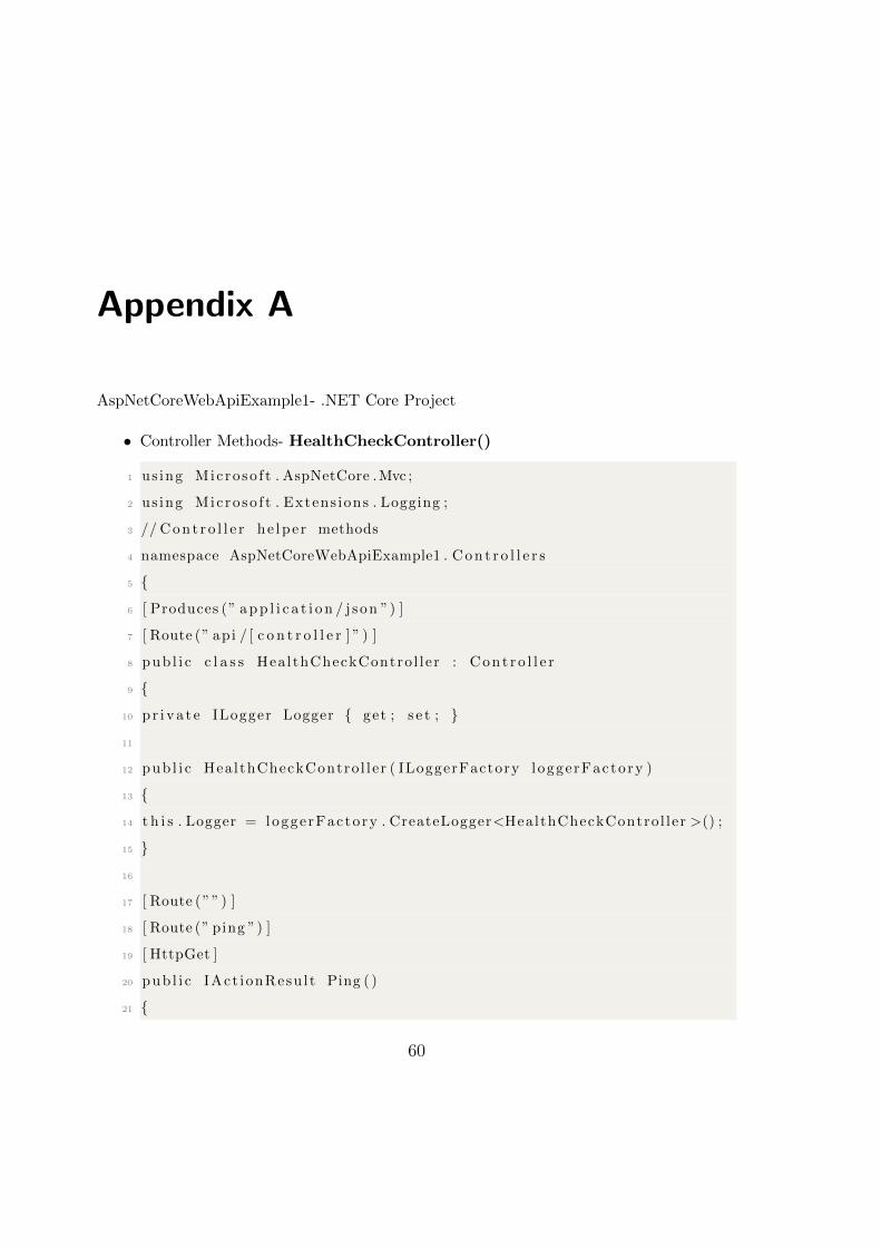
Appendix A
AspNetCoreWebApiExample1- .NET Core Project
• Controller Methods- HealthCheckController()
1 us ing Micro so f t . AspNetCore .Mvc ;
2 us ing Micro so f t . Extens ions . Logging ;
3 // C o n t r o l l e r he lpe r methods
4 namespace AspNetCoreWebApiExample1 . C o n t r o l l e r s
5 {
6 [ Produces (” a p p l i c a t i o n / j son ”) ]
7 [ Route (” api / [ c o n t r o l l e r ] ” ) ]
8 pub l i c c l a s s HealthCheckContro l ler : C o n t r o l l e r
9 {
10 p r i v a t e ILogger Logger { get ; s e t ; }
11
12 pub l i c HealthCheckContro l ler ( ILoggerFactory loggerFactory )
13 {
14 t h i s . Logger = loggerFactory . CreateLogger<HealthCheckControl ler >() ;
15 }
16
17 [ Route (””) ]
18 [ Route (” ping ”) ]
19 [ HttpGet ]
20 pub l i c IAct ionResu l t Ping ( )
21 {
60
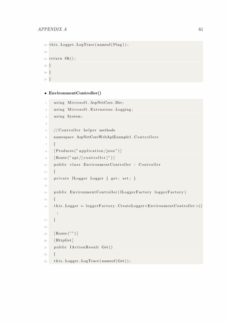
APPENDIX A 61
22 t h i s . Logger . LogTrace ( nameof ( Ping ) ) ;
23
24 re turn Ok( ) ;
25 }
26 }
27 }
• EnvironmentController()
1 us ing Microso f t . AspNetCore .Mvc ;
2 us ing Microso f t . Extens ions . Logging ;
3 us ing System ;
4
5 // C o n t r o l l e r he lpe r methods
6 namespace AspNetCoreWebApiExample1 . C o n t r o l l e r s
7 {
8 [ Produces (” a p p l i c a t i o n / j son ”) ]
9 [ Route (” api / [ c o n t r o l l e r ] ” ) ]
10 pub l i c c l a s s EnvironmentControl ler : C o n t r o l l e r
11 {
12 p r i v a t e ILogger Logger { get ; s e t ; }
13
14 pub l i c EnvironmentControl ler ( ILoggerFactory loggerFactory )
15 {
16 t h i s . Logger = loggerFactory . CreateLogger<EnvironmentControl ler >()
;
17 }
18
19 [ Route (””) ]
20 [ HttpGet ]
21 pub l i c IAct ionResu l t Get ( )
22 {
23 t h i s . Logger . LogTrace ( nameof ( Get ) ) ;
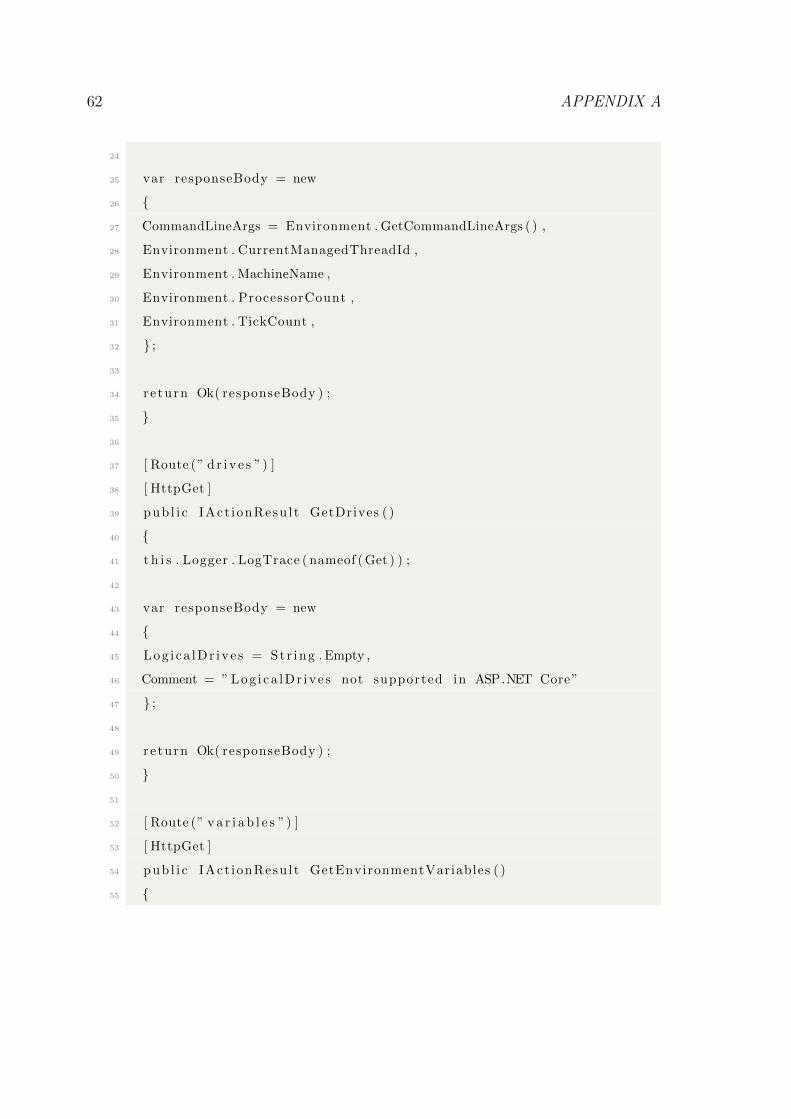
62 APPENDIX A
24
25 var responseBody = new
26 {
27 CommandLineArgs = Environment . GetCommandLineArgs ( ) ,
28 Environment . CurrentManagedThreadId ,
29 Environment . MachineName ,
30 Environment . ProcessorCount ,
31 Environment . TickCount ,
32 } ;
33
34 re turn Ok( responseBody ) ;
35 }
36
37 [ Route (” d r i v e s ”) ]
38 [ HttpGet ]
39 pub l i c IAct ionResu l t GetDrives ( )
40 {
41 t h i s . Logger . LogTrace ( nameof ( Get ) ) ;
42
43 var responseBody = new
44 {
45 Log i ca lDr ive s = St r ing . Empty ,
46 Comment = ” Log i ca lDr ive s not supported in ASP.NET Core”
47 } ;
48
49 re turn Ok( responseBody ) ;
50 }
51
52 [ Route (” v a r i a b l e s ”) ]
53 [ HttpGet ]
54 pub l i c IAct ionResu l t GetEnvironmentVariables ( )
55 {
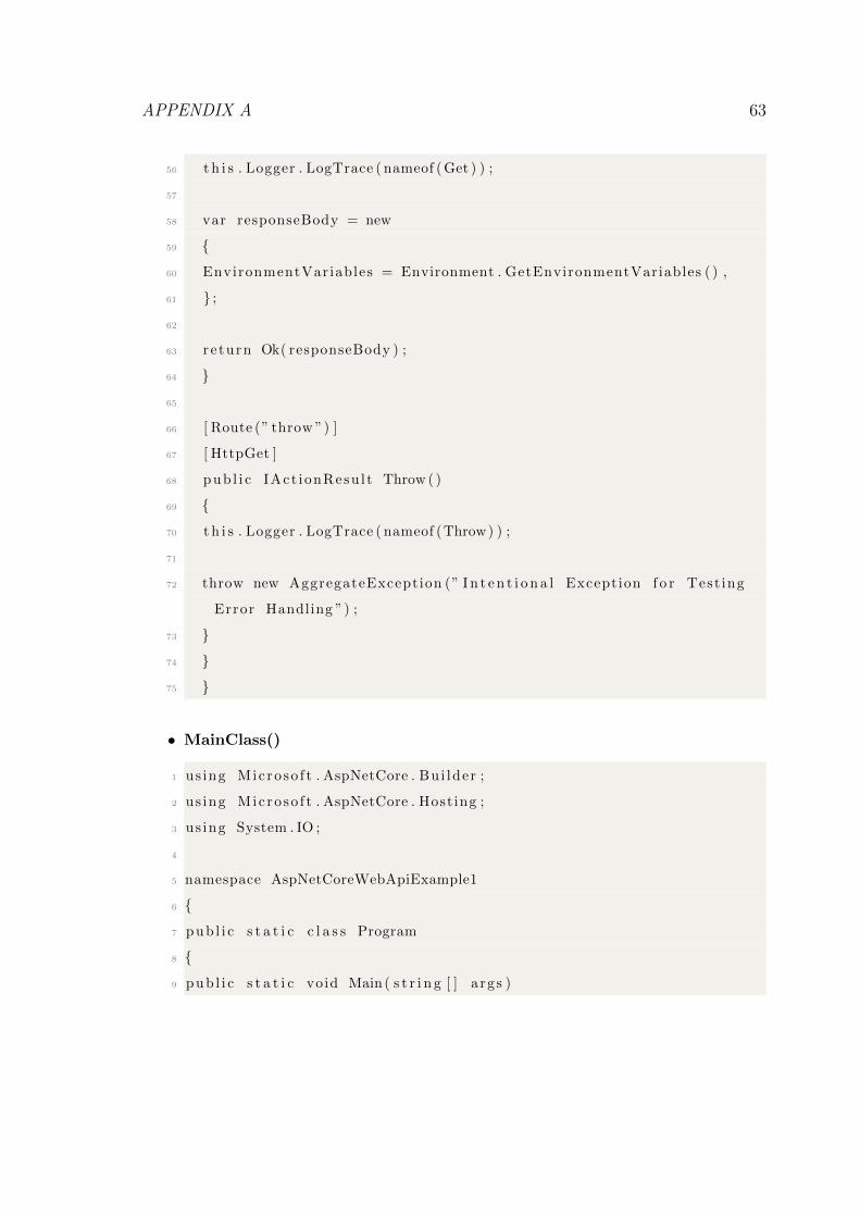
APPENDIX A 63
56 t h i s . Logger . LogTrace ( nameof ( Get ) ) ;
57
58 var responseBody = new
59 {
60 EnvironmentVariables = Environment . GetEnvironmentVariables ( ) ,
61 } ;
62
63 re turn Ok( responseBody ) ;
64 }
65
66 [ Route (” throw ”) ]
67 [ HttpGet ]
68 pub l i c IAct ionResu l t Throw ( )
69 {
70 t h i s . Logger . LogTrace ( nameof (Throw) ) ;
71
72 throw new AggregateException (” I n t e n t i o n a l Exception f o r Test ing
Error Handling ”) ;
73 }
74 }
75 }
• MainClass()
1 us ing Microso f t . AspNetCore . Bu i lder ;
2 us ing Microso f t . AspNetCore . Hosting ;
3 us ing System . IO ;
4
5 namespace AspNetCoreWebApiExample1
6 {
7 pub l i c s t a t i c c l a s s Program
8 {
9 pub l i c s t a t i c void Main ( s t r i n g [ ] a rgs )
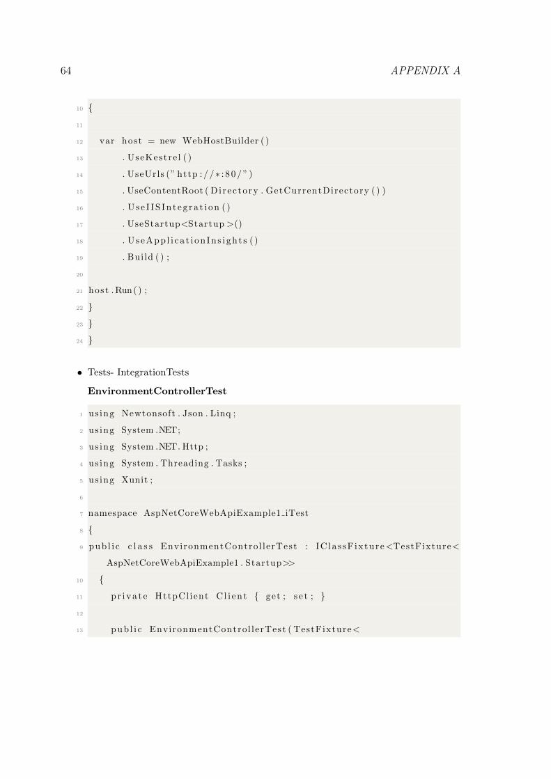
64 APPENDIX A
10 {
11
12 var host = new WebHostBuilder ( )
13 . UseKestre l ( )
14 . UseUrls (” http : / /∗ : 8 0 / ” )
15 . UseContentRoot ( Di rec tory . GetCurrentDirectory ( ) )
16 . U s e I IS In t eg ra t i on ( )
17 . UseStartup<Startup >()
18 . Us eApp l i c a t i on In s i gh t s ( )
19 . Bui ld ( ) ;
20
21 host . Run( ) ;
22 }
23 }
24 }
• Tests- IntegrationTests
EnvironmentControllerTest
1 us ing Newtonsoft . Json . Linq ;
2 us ing System .NET;
3 us ing System .NET. Http ;
4 us ing System . Threading . Tasks ;
5 us ing Xunit ;
6
7 namespace AspNetCoreWebApiExample1 iTest
8 {
9 pub l i c c l a s s EnvironmentControl lerTest : IC las sF ixture<TestFixture<
AspNetCoreWebApiExample1 . Startup>>
10 {
11 p r i v a t e HttpCl ient C l i en t { get ; s e t ; }
12
13 pub l i c EnvironmentControl lerTest ( TestFixture<
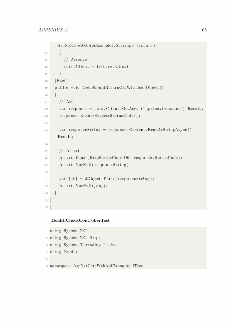
APPENDIX A 65
AspNetCoreWebApiExample1 . Startup> f i x t u r e )
14 {
15 // Arrange
16 t h i s . C l i en t = f i x t u r e . C l i en t ;
17 }
18 [ Fact ]
19 pub l i c void Get ShouldReturnOk WithJsonObject ( )
20 {
21 // Act
22 var re sponse = t h i s . C l i en t . GetAsync (” api / environment ”) . Result ;
23 re sponse . EnsureSuccessStatusCode ( ) ;
24
25 var r e spons eS t r i ng = response . Content . ReadAsStringAsync ( ) .
Result ;
26
27 // Assert
28 Assert . Equal ( HttpStatusCode .OK, response . StatusCode ) ;
29 Assert . NotNull ( r e spons eS t r i ng ) ;
30
31 var j o b j = JObject . Parse ( r e spons eS t r i ng ) ;
32 Assert . NotNull ( j o b j ) ;
33 }
34 }
35 }
HealthCheckControllerTest
1 us ing System .NET;
2 us ing System .NET. Http ;
3 us ing System . Threading . Tasks ;
4 us ing Xunit ;
5
6 namespace AspNetCoreWebApiExample1 iTest
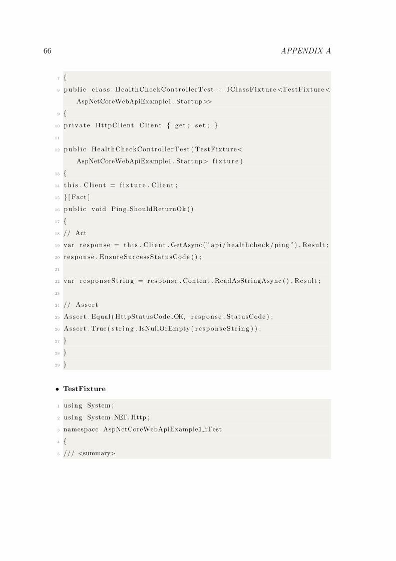
66 APPENDIX A
7 {
8 pub l i c c l a s s HealthCheckContro l lerTest : IC las sF ixture<TestFixture<
AspNetCoreWebApiExample1 . Startup>>
9 {
10 p r i v a t e HttpCl ient C l i en t { get ; s e t ; }
11
12 pub l i c HealthCheckContro l lerTest ( TestFixture<
AspNetCoreWebApiExample1 . Startup> f i x t u r e )
13 {
14 t h i s . C l i en t = f i x t u r e . C l i en t ;
15 } [ Fact ]
16 pub l i c void Ping ShouldReturnOk ( )
17 {
18 // Act
19 var re sponse = t h i s . C l i en t . GetAsync (” api / hea l thcheck / ping ”) . Result ;
20 re sponse . EnsureSuccessStatusCode ( ) ;
21
22 var r e spons eS t r i ng = response . Content . ReadAsStringAsync ( ) . Result ;
23
24 // Assert
25 Assert . Equal ( HttpStatusCode .OK, response . StatusCode ) ;
26 Assert . True ( s t r i n g . IsNullOrEmpty ( r e spons eS t r i ng ) ) ;
27 }
28 }
29 }
• TestFixture
1 us ing System ;
2 us ing System .NET. Http ;
3 namespace AspNetCoreWebApiExample1 iTest
4 {
5 /// <summary>
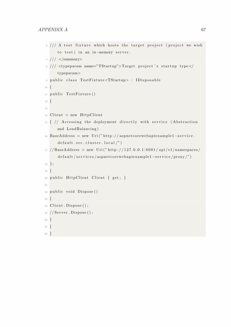
APPENDIX A 67
6 /// A t e s t f i x t u r e which hos t s the t a r g e t p r o j e c t ( p r o j e c t we wish
to t e s t ) in an in−memory s e r v e r .
7 /// </summary>
8 /// <typeparam name=”TStartup”>Target pro j e c t ’ s s ta r tup type</
typeparam>
9 pub l i c c l a s s TestFixture<TStartup> : ID i sposab l e
10 {
11 pub l i c TestFixture ( )
12 {
13
14 Cl i en t = new HttpCl ient
15 { // Access ing the deployment d i r e c t l y with s e r v i c e ( Abstract ion
and LoadBalancing )
16 BaseAddress = new Uri (” http :// aspnetcorewebapiexample1−s e r v i c e .
d e f a u l t . svc . c l u s t e r . l o c a l /”)
17 // BaseAddress = new Uri (” http : / / 1 2 7 . 0 . 0 . 1 : 8 0 0 1 / api /v1/namespaces/
d e f a u l t / s e r v i c e s / aspnetcorewebapiexample1−s e r v i c e /proxy /”)
18 } ;
19 }
20 pub l i c HttpCl ient C l i en t { get ; }
21
22 pub l i c void Dispose ( )
23 {
24 Cl i en t . Dispose ( ) ;
25 // Server . Dispose ( ) ;
26 }
27 }
28 }
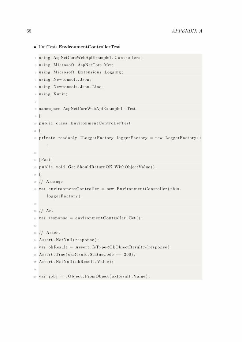
68 APPENDIX A
• UnitTests EnvironmentControllerTest
1 us ing AspNetCoreWebApiExample1 . C o n t r o l l e r s ;
2 us ing Micro so f t . AspNetCore .Mvc ;
3 us ing Micro so f t . Extens ions . Logging ;
4 us ing Newtonsoft . Json ;
5 us ing Newtonsoft . Json . Linq ;
6 us ing Xunit ;
7
8 namespace AspNetCoreWebApiExample1 uTest
9 {
10 pub l i c c l a s s EnvironmentControl lerTest
11 {
12 p r i v a t e readonly ILoggerFactory loggerFactory = new LoggerFactory ( )
;
13
14 [ Fact ]
15 pub l i c void Get ShouldReturnOK WithObjectValue ( )
16 {
17 // Arrange
18 var env i ronmentContro l l e r = new EnvironmentControl ler ( t h i s .
l oggerFactory ) ;
19
20 // Act
21 var re sponse = env i ronmentContro l l e r . Get ( ) ;
22
23 // Assert
24 Assert . NotNull ( r e sponse ) ;
25 var okResult = Assert . IsType<OkObjectResult>( re sponse ) ;
26 Assert . True ( okResult . StatusCode == 200) ;
27 Assert . NotNull ( okResult . Value ) ;
28
29 var j o b j = JObject . FromObject ( okResult . Value ) ;
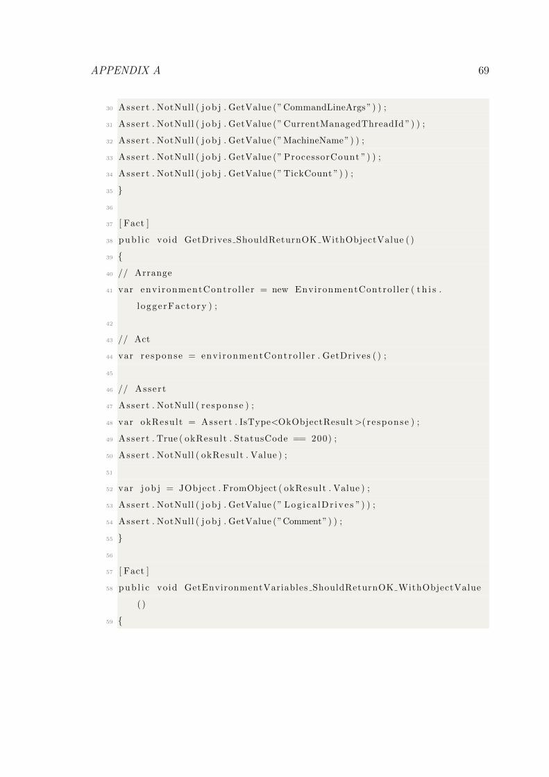
APPENDIX A 69
30 Assert . NotNull ( j o b j . GetValue (” CommandLineArgs ”) ) ;
31 Assert . NotNull ( j o b j . GetValue (” CurrentManagedThreadId ”) ) ;
32 Assert . NotNull ( j o b j . GetValue (”MachineName”) ) ;
33 Assert . NotNull ( j o b j . GetValue (” ProcessorCount ”) ) ;
34 Assert . NotNull ( j o b j . GetValue (” TickCount ”) ) ;
35 }
36
37 [ Fact ]
38 pub l i c void GetDrives ShouldReturnOK WithObjectValue ( )
39 {
40 // Arrange
41 var env i ronmentContro l l e r = new EnvironmentControl ler ( t h i s .
l oggerFactory ) ;
42
43 // Act
44 var re sponse = env i ronmentContro l l e r . GetDrives ( ) ;
45
46 // Assert
47 Assert . NotNull ( r e sponse ) ;
48 var okResult = Assert . IsType<OkObjectResult>( re sponse ) ;
49 Assert . True ( okResult . StatusCode == 200) ;
50 Assert . NotNull ( okResult . Value ) ;
51
52 var j o b j = JObject . FromObject ( okResult . Value ) ;
53 Assert . NotNull ( j o b j . GetValue (” Log i ca lDr ive s ”) ) ;
54 Assert . NotNull ( j o b j . GetValue (”Comment”) ) ;
55 }
56
57 [ Fact ]
58 pub l i c void GetEnvironmentVariables ShouldReturnOK WithObjectValue
( )
59 {
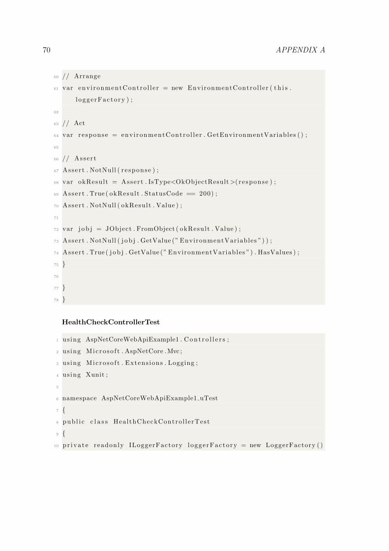
70 APPENDIX A
60 // Arrange
61 var env i ronmentContro l l e r = new EnvironmentControl ler ( t h i s .
l oggerFactory ) ;
62
63 // Act
64 var re sponse = env i ronmentContro l l e r . GetEnvironmentVariables ( ) ;
65
66 // Assert
67 Assert . NotNull ( r e sponse ) ;
68 var okResult = Assert . IsType<OkObjectResult>( re sponse ) ;
69 Assert . True ( okResult . StatusCode == 200) ;
70 Assert . NotNull ( okResult . Value ) ;
71
72 var j o b j = JObject . FromObject ( okResult . Value ) ;
73 Assert . NotNull ( j o b j . GetValue (” EnvironmentVariables ”) ) ;
74 Assert . True ( j o b j . GetValue (” EnvironmentVariables ”) . HasValues ) ;
75 }
76
77 }
78 }
HealthCheckControllerTest
1 us ing AspNetCoreWebApiExample1 . C o n t r o l l e r s ;
2 us ing Micro so f t . AspNetCore .Mvc ;
3 us ing Micro so f t . Extens ions . Logging ;
4 us ing Xunit ;
5
6 namespace AspNetCoreWebApiExample1 uTest
7 {
8 pub l i c c l a s s HealthCheckContro l lerTest
9 {
10 p r i v a t e readonly ILoggerFactory loggerFactory = new LoggerFactory ( )
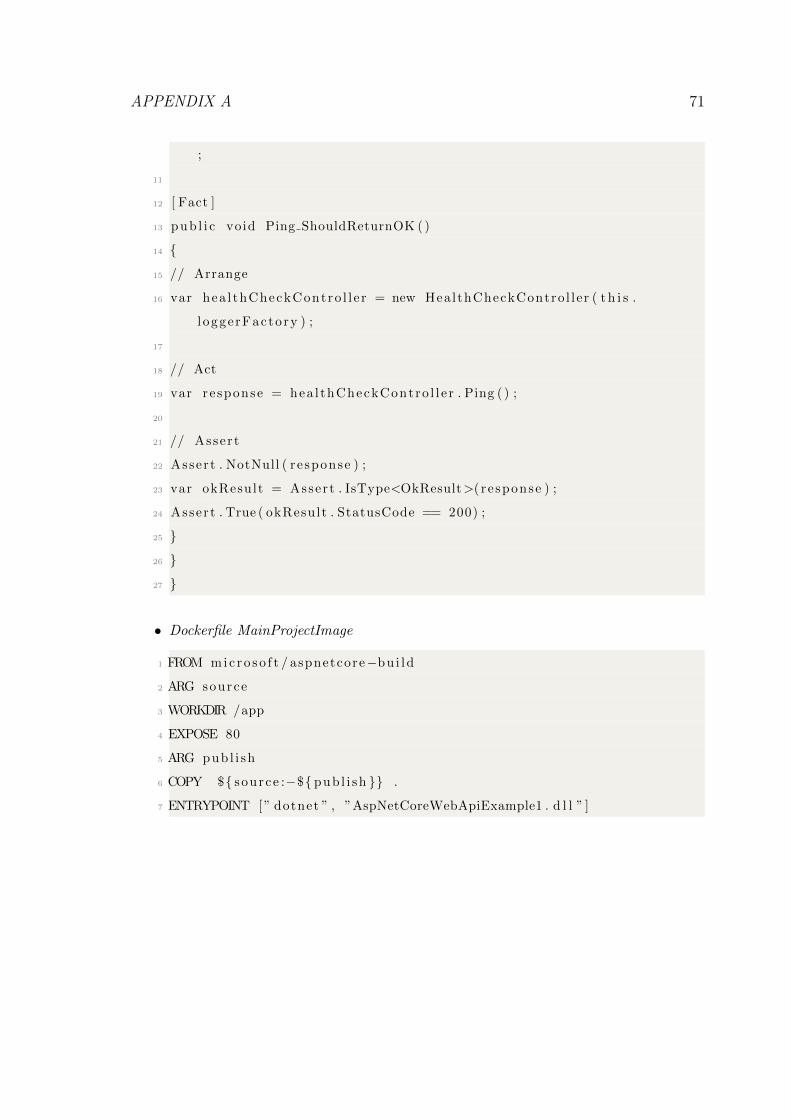
APPENDIX A 71
;
11
12 [ Fact ]
13 pub l i c void Ping ShouldReturnOK ( )
14 {
15 // Arrange
16 var hea l thCheckContro l l e r = new HealthCheckContro l ler ( t h i s .
l oggerFactory ) ;
17
18 // Act
19 var re sponse = hea l thCheckContro l l e r . Ping ( ) ;
20
21 // Assert
22 Assert . NotNull ( r e sponse ) ;
23 var okResult = Assert . IsType<OkResult>( re sponse ) ;
24 Assert . True ( okResult . StatusCode == 200) ;
25 }
26 }
27 }
• Dockerfile MainProjectImage
1 FROM mic ro so f t / aspnetcore−bu i ld
2 ARG source
3 WORKDIR /app
4 EXPOSE 80
5 ARG pub l i sh
6 COPY ${ source :−${ pub l i sh }} .
7 ENTRYPOINT [ ” dotnet ” , ”AspNetCoreWebApiExample1 . d l l ” ]
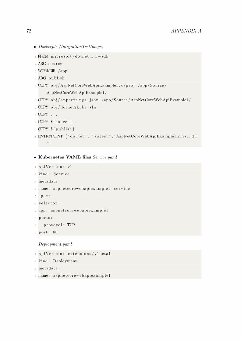
72 APPENDIX A
• Dockerfile (IntegrationTestImage)
1 FROM mic ro so f t / dotnet :1.1− sdk
2 ARG source
3 WORKDIR /app
4 ARG pub l i sh
5 COPY obj /AspNetCoreWebApiExample1 . c s p r o j /app/ Source /
AspNetCoreWebApiExample1/
6 COPY obj / apps e t t i ng s . j son /app/ Source /AspNetCoreWebApiExample1/
7 COPY obj / dotnet2kube . s l n .
8 COPY . .
9 COPY ${ source } .
10 COPY ${ pub l i sh } .
11 ENTRYPOINT [ ” dotnet ” , ” v s t e s t ” ,” AspNetCoreWebApiExample1 iTest . d l l
” ]
• Kubernetes YAML files Service.yaml
1 ap iVers ion : v1
2 kind : S e r v i c e
3 metadata :
4 name : aspnetcorewebapiexample1−s e r v i c e
5 spec :
6 s e l e c t o r :
7 app : aspnetcorewebapiexample1
8 por t s :
9 − pro to co l : TCP
10 port : 80
Deployment.yaml
1 ap iVers ion : ex t en s i on s / v1beta1
2 kind : Deployment
3 metadata :
4 name : aspnetcorewebapiexample1
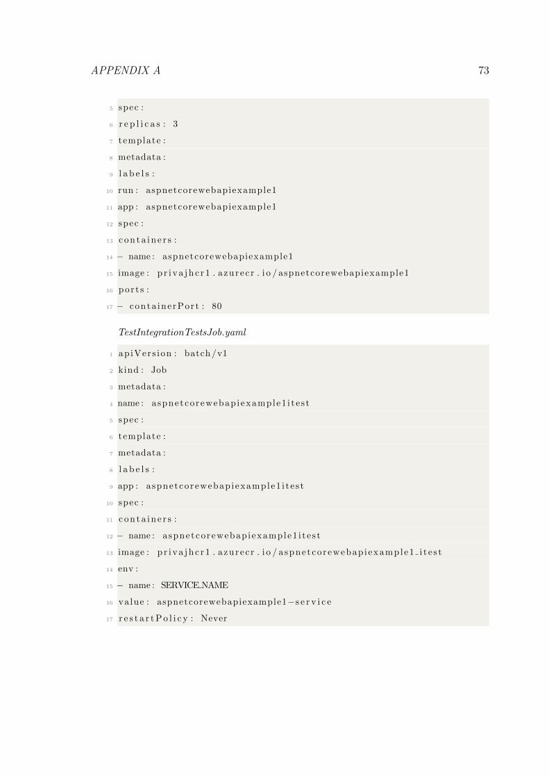
APPENDIX A 73
5 spec :
6 r e p l i c a s : 3
7 template :
8 metadata :
9 l a b e l s :
10 run : aspnetcorewebapiexample1
11 app : aspnetcorewebapiexample1
12 spec :
13 c o n t a i n e r s :
14 − name : aspnetcorewebapiexample1
15 image : p r i v a j h c r 1 . azurec r . i o / aspnetcorewebapiexample1
16 por t s :
17 − conta inerPort : 80
TestIntegrationTestsJob.yaml
1 ap iVers ion : batch /v1
2 kind : Job
3 metadata :
4 name : aspnetcorewebap iexample1 i t e s t
5 spec :
6 template :
7 metadata :
8 l a b e l s :
9 app : aspnetcorewebap iexample1 i t e s t
10 spec :
11 c o n t a i n e r s :
12 − name : aspnetcorewebap iexample1 i t e s t
13 image : p r i v a j h c r 1 . azurec r . i o / aspnetcorewebap i example1 i t e s t
14 env :
15 − name : SERVICE NAME
16 value : aspnetcorewebapiexample1−s e r v i c e
17 r e s t a r t P o l i c y : Never
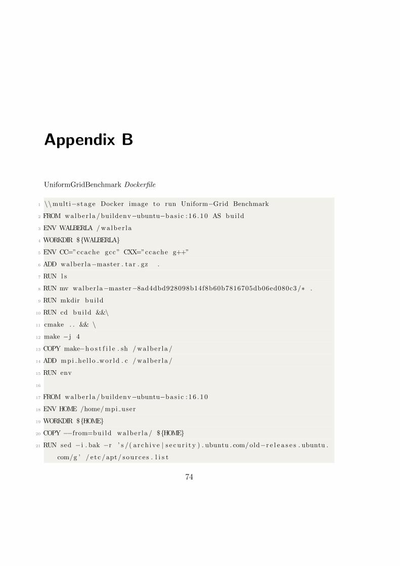
Appendix B
UniformGridBenchmark Dockerfile
1 \\multi−s tage Docker image to run Uniform−Grid Benchmark
2 FROM walber la / bui ldenv−ubuntu−bas i c : 1 6 . 1 0 AS bu i ld
3 ENV WALBERLA / walber la
4 WORKDIR ${WALBERLA}
5 ENV CC=”ccache gcc ” CXX=”ccache g++”
6 ADD walber la−master . ta r . gz .
7 RUN l s
8 RUN mv walber la−master−8ad4dbd928098b14f8b60b7816705db06ed080c3 /∗ .
9 RUN mkdir bu i ld
10 RUN cd bu i ld &&\
11 cmake . . && \
12 make −j 4
13 COPY make−h o s t f i l e . sh / wa lber la /
14 ADD mpi he l l o wor ld . c / wa lber la /
15 RUN env
16
17 FROM walber la / bui ldenv−ubuntu−bas i c : 1 6 . 1 0
18 ENV HOME /home/ mpi user
19 WORKDIR ${HOME}
20 COPY −−from=bui ld wa lber la / ${HOME}
21 RUN sed − i . bak −r ’ s /( a r ch ive | s e c u r i t y ) . ubuntu . com/ old−r e l e a s e s . ubuntu .
com/g ’ / e t c / apt / sour c e s . l i s t
74
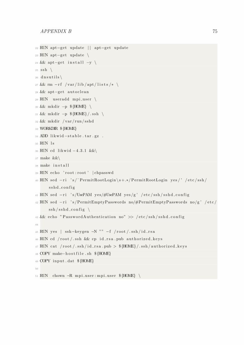
APPENDIX B 75
22 RUN apt−get update | | apt−get update
23 RUN apt−get update \
24 && apt−get i n s t a l l −y \
25 ssh \
26 d n s u t i l s \
27 && rm −r f / var / l i b / apt / l i s t s /∗ \
28 && apt−get autoc l ean
29 RUN useradd mpi user \
30 && mkdir −p ${HOME} \
31 && mkdir −p ${HOME}/ . ssh \
32 && mkdir / var /run/ sshd
33 WORKDIR ${HOME}
34 ADD l ikwid−s t a b l e . ta r . gz .
35 RUN l s
36 RUN cd l ikwid −4.3 .1 &&\
37 make &&\
38 make i n s t a l l
39 RUN echo ’ root : root ’ | chpasswd
40 RUN sed − r i ’ s /ˆ PermitRootLogin\ s +.∗/ PermitRootLogin yes / ’ / e t c / ssh /
s s h d c o n f i g
41 RUN sed − r i ’ s /UsePAM yes/#UsePAM yes /g ’ / e t c / ssh / s s h d c o n f i g
42 RUN sed − r i ’ s /PermitEmptyPasswords no/#PermitEmptyPasswords no/g ’ / e t c /
ssh / s s h d c o n f i g \
43 && echo ” PasswordAuthenticat ion no” >> / e tc / ssh / s s h d c o n f i g
44
45 RUN yes | ssh−keygen −N ”” −f / root / . ssh / i d r s a
46 RUN cd / root / . ssh && cp i d r s a . pub author i z ed keys
47 RUN cat / root / . ssh / i d r s a . pub > ${HOME}/ . ssh / author i z ed keys
48 COPY make−h o s t f i l e . sh ${HOME}
49 COPY input . dat ${HOME}
50
51 RUN chown −R mpi user : mpi user ${HOME} \
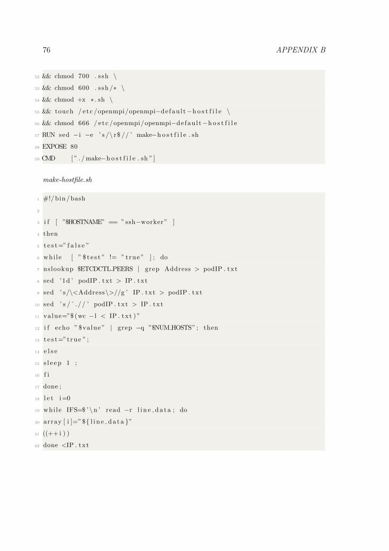
76 APPENDIX B
52 && chmod 700 . ssh \
53 && chmod 600 . ssh /∗ \
54 && chmod +x ∗ . sh \
55 && touch / e tc /openmpi/openmpi−de fau l t−h o s t f i l e \
56 && chmod 666 / e tc /openmpi/openmpi−de fau l t−h o s t f i l e
57 RUN sed − i −e ’ s /\ r$ // ’ make−h o s t f i l e . sh
58 EXPOSE 80
59 CMD [ ” . / make−h o s t f i l e . sh ” ]
make-hostfile.sh
1 #!/ bin /bash
2
3 i f [ ”$HOSTNAME” == ” ssh−worker ” ]
4 then
5 t e s t=” f a l s e ”
6 whi le [ ” $ t e s t ” != ” true ” ] ; do
7 nslookup $ETCDCTL PEERS | grep Address > podIP . txt
8 sed ’1d ’ podIP . txt > IP . txt
9 sed ’ s/\<Address\>//g ’ IP . txt > podIP . txt
10 sed ’ s /ˆ .// ’ podIP . txt > IP . txt
11 value=”$ (wc − l < IP . txt ) ”
12 i f echo ” $value ” | grep −q ”$NUM HOSTS” ; then
13 t e s t=”true ” ;
14 e l s e
15 s l e e p 1 ;
16 f i
17 done ;
18 l e t i=0
19 whi le IFS=$ ’\n ’ read −r l i n e d a t a ; do
20 array [ i ]=”${ l i n e d a t a }”
21 ((++ i ) )
22 done <IP . txt
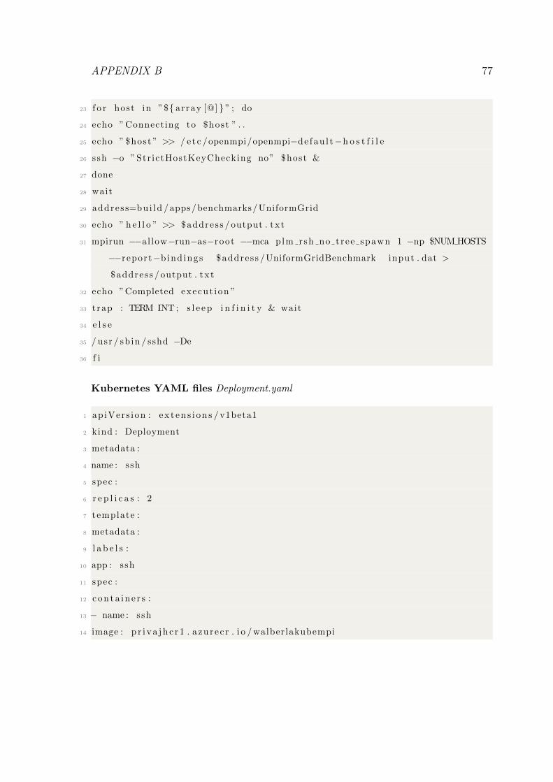
APPENDIX B 77
23 f o r host in ”${ array [@] } ” ; do
24 echo ” Connecting to $host ” . .
25 echo ” $host ” >> / e tc /openmpi/openmpi−de fau l t−h o s t f i l e
26 ssh −o ” Str ictHostKeyChecking no” $host &
27 done
28 wait
29 address=bu i ld /apps/benchmarks/UniformGrid
30 echo ” h e l l o ” >> $address / output . txt
31 mpirun −−al low−run−as−root −−mca plm rsh no tree spawn 1 −np $NUM HOSTS
−−report−bind ings $address /UniformGridBenchmark input . dat >
$address / output . txt
32 echo ”Completed execut ion ”
33 trap : TERM INT ; s l e e p i n f i n i t y & wait
34 e l s e
35 / usr / sb in / sshd −De
36 f i
Kubernetes YAML files Deployment.yaml
1 ap iVers ion : ex t en s i on s / v1beta1
2 kind : Deployment
3 metadata :
4 name : ssh
5 spec :
6 r e p l i c a s : 2
7 template :
8 metadata :
9 l a b e l s :
10 app : ssh
11 spec :
12 c o n t a i n e r s :
13 − name : ssh
14 image : p r i v a j h c r 1 . azurec r . i o / walberlakubempi
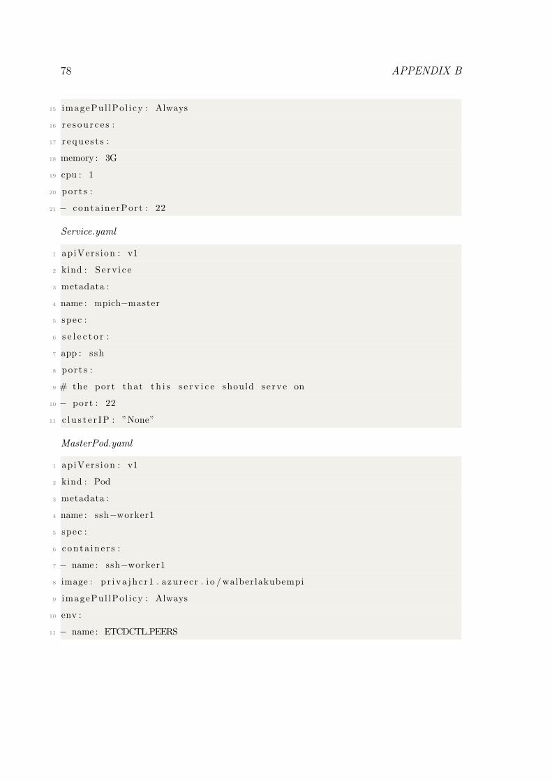
78 APPENDIX B
15 imagePul lPo l i cy : Always
16 r e s o u r c e s :
17 r e q u e s t s :
18 memory : 3G
19 cpu : 1
20 por t s :
21 − conta inerPort : 22
Service.yaml
1 ap iVers ion : v1
2 kind : S e r v i c e
3 metadata :
4 name : mpich−master
5 spec :
6 s e l e c t o r :
7 app : ssh
8 por t s :
9 # the port that t h i s s e r v i c e should s e rve on
10 − port : 22
11 c l u s t e r I P : ”None”
MasterPod.yaml
1 ap iVers ion : v1
2 kind : Pod
3 metadata :
4 name : ssh−worker1
5 spec :
6 c o n t a i n e r s :
7 − name : ssh−worker1
8 image : p r i v a j h c r 1 . azurec r . i o / walberlakubempi
9 imagePul lPo l i cy : Always
10 env :
11 − name : ETCDCTL PEERS
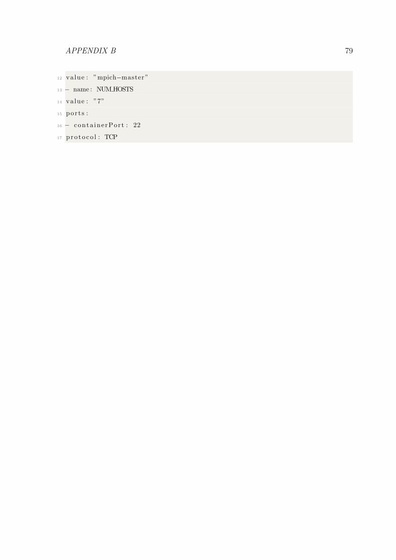
APPENDIX B 79
12 value : ”mpich−master ”
13 − name : NUM HOSTS
14 value : ”7”
15 por t s :
16 − conta inerPort : 22
17 pro to co l : TCP
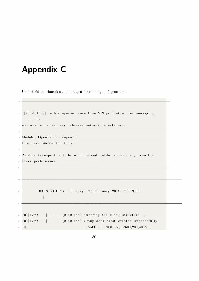
Appendix C
UniforGrid benchmark sample output for running on 6-processes
1 −−−−−−−−−−−−−−−−−−−−−−−−−−−−−−−−−−−−−−−−−−−−−−−−−−−−−−−−−−−−−−−−−−−−−−−−−−
2 [ [ 9 6 4 4 , 1 ] , 0 ] : A high−performance Open MPI point−to−po int messaging
module
3 was unable to f i n d any r e l e v a n t network i n t e r f a c e s :
4
5 Module : OpenFabrics ( openib )
6 Host : ssh−76c88784cb−fm6gl
7
8 Another t ranspo r t w i l l be used instead , although t h i s may r e s u l t in
9 lower performance .
10 −−−−−−−−−−−−−−−−−−−−−−−−−−−−−−−−−−−−−−−−−−−−−−−−−−−−−−−−−−−−−−−−−−−−−−−−−−
11 ================================================================================
12 | BEGIN LOGGING − Tuesday , 27 . February 2018 , 22 : 19 : 06
|
13 ================================================================================
14 [ 0 ] [ INFO ]−−−−−−(0.000 sec ) Creat ing the block s t r u c t u r e . . .
15 [ 0 ] [ INFO ]−−−−−−(0.000 sec ) SetupBlockForest c r ea ted s u c c e s s f u l l y :
16 [ 0 ] − AABB: [ <0 ,0 ,0> , <600 ,200 ,400> ]
80
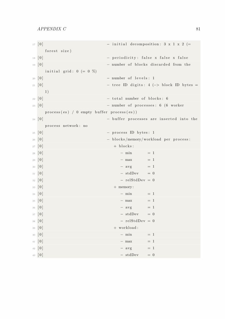
APPENDIX C 81
17 [ 0 ] − i n i t i a l decompos it ion : 3 x 1 x 2 (=
f o r e s t s i z e )
18 [ 0 ] − p e r i o d i c i t y : f a l s e x f a l s e x f a l s e
19 [ 0 ] − number o f b locks d i s ca rded from the
i n i t i a l g r i d : 0 (= 0 %)
20 [ 0 ] − number o f l e v e l s : 1
21 [ 0 ] − t r e e ID d i g i t s : 4 (−> block ID bytes =
1)
22 [ 0 ] − t o t a l number o f b locks : 6
23 [ 0 ] − number o f p r o c e s s e s : 6 (6 worker
p roce s s ( es ) / 0 empty b u f f e r p roce s s ( es ) )
24 [ 0 ] − b u f f e r p r o c e s s e s are i n s e r t e d in to the
proce s s network : no
25 [ 0 ] − proce s s ID bytes : 1
26 [ 0 ] − b locks /memory/ workload per p roce s s :
27 [ 0 ] + b locks :
28 [ 0 ] − min = 1
29 [ 0 ] − max = 1
30 [ 0 ] − avg = 1
31 [ 0 ] − stdDev = 0
32 [ 0 ] − re lStdDev = 0
33 [ 0 ] + memory :
34 [ 0 ] − min = 1
35 [ 0 ] − max = 1
36 [ 0 ] − avg = 1
37 [ 0 ] − stdDev = 0
38 [ 0 ] − re lStdDev = 0
39 [ 0 ] + workload :
40 [ 0 ] − min = 1
41 [ 0 ] − max = 1
42 [ 0 ] − avg = 1
43 [ 0 ] − stdDev = 0
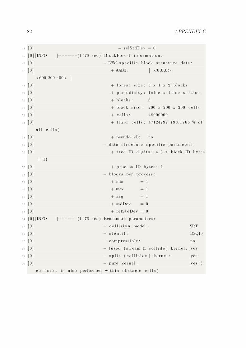
82 APPENDIX C
44 [ 0 ] − re lStdDev = 0
45 [ 0 ] [ INFO ]−−−−−−(1.476 sec ) BlockForest in fo rmat ion :
46 [ 0 ] − LBM−s p e c i f i c b lock s t r u c t u r e data :
47 [ 0 ] + AABB: [ <0 ,0 ,0> ,
<600 ,200 ,400> ]
48 [ 0 ] + f o r e s t s i z e : 3 x 1 x 2 b locks
49 [ 0 ] + p e r i o d i c i t y : f a l s e x f a l s e x f a l s e
50 [ 0 ] + b locks : 6
51 [ 0 ] + block s i z e : 200 x 200 x 200 c e l l s
52 [ 0 ] + c e l l s : 48000000
53 [ 0 ] + f l u i d c e l l s : 47124792 (98 .1766 % of
a l l c e l l s )
54 [ 0 ] + pseudo 2D: no
55 [ 0 ] − data s t r u c t u r e s p e c i f i c parameters :
56 [ 0 ] + t r e e ID d i g i t s : 4 (−> block ID bytes
= 1)
57 [ 0 ] + proce s s ID bytes : 1
58 [ 0 ] − b locks per p roce s s :
59 [ 0 ] + min = 1
60 [ 0 ] + max = 1
61 [ 0 ] + avg = 1
62 [ 0 ] + stdDev = 0
63 [ 0 ] + relStdDev = 0
64 [ 0 ] [ INFO ]−−−−−−(1.476 sec ) Benchmark parameters :
65 [ 0 ] − c o l l i s i o n model : SRT
66 [ 0 ] − s t e n c i l : D3Q19
67 [ 0 ] − compres s ib l e : no
68 [ 0 ] − fu sed ( stream & c o l l i d e ) ke rne l : yes
69 [ 0 ] − s p l i t ( c o l l i s i o n ) ke rne l : yes
70 [ 0 ] − pure ke rne l : yes (
c o l l i s i o n i s a l s o performed with in o b s t a c l e c e l l s )
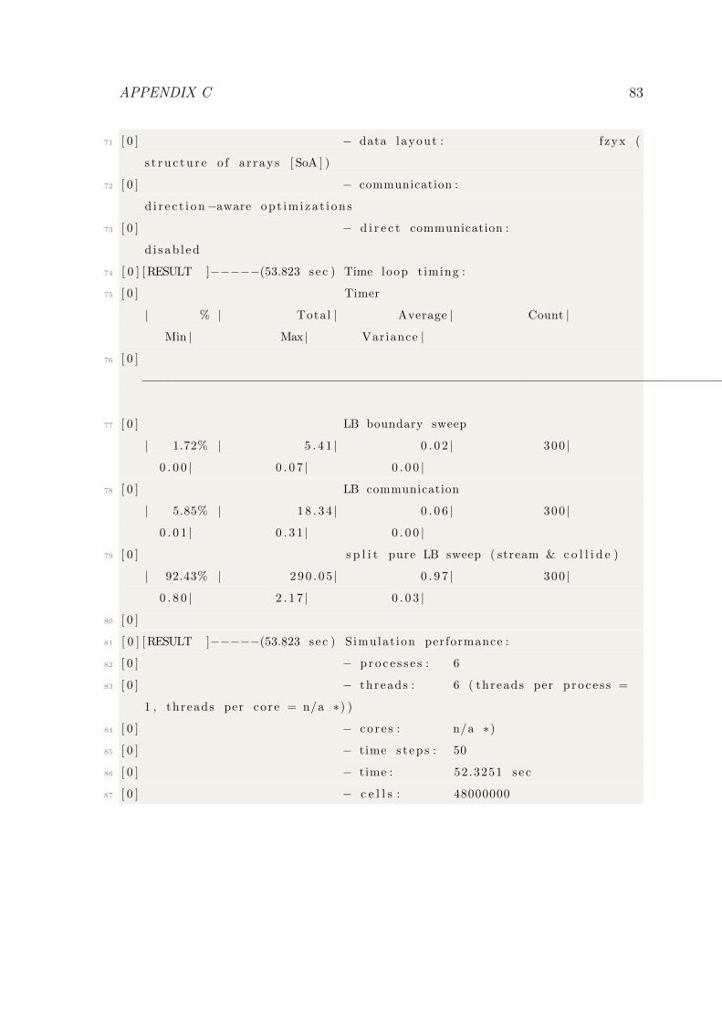
APPENDIX C 83
71 [ 0 ] − data layout : f zyx (
s t r u c t u r e o f a r rays [ SoA ] )
72 [ 0 ] − communication :
d i r e c t i o n−aware op t im i za t i on s
73 [ 0 ] − d i r e c t communication :
d i s ab l ed
74 [ 0 ] [ RESULT ]−−−−−(53.823 sec ) Time loop t iming :
75 [ 0 ] Timer
| % | Total | Average | Count |
Min | Max | Variance |
76 [ 0 ]
−−−−−−−−−−−−−−−−−−−−−−−−−−−−−−−−−−−−−−−−−−−−−−−−−−−−−−−−−−−−−−−−−−−−−−−−−−−−−−−−−−−−−−−−−−−−−−−−−−−−−−−−−−−−−−−−−−−−−−−−−−−−−−−−−−−−−−−−−−−−−−−−−−−−
77 [ 0 ] LB boundary sweep
| 1.72% | 5 . 4 1 | 0 . 0 2 | 300 |
0 . 0 0 | 0 . 0 7 | 0 . 0 0 |
78 [ 0 ] LB communication
| 5.85% | 1 8 . 3 4 | 0 . 0 6 | 300 |
0 . 0 1 | 0 . 3 1 | 0 . 0 0 |
79 [ 0 ] s p l i t pure LB sweep ( stream & c o l l i d e )
| 92.43% | 2 9 0 . 0 5 | 0 . 9 7 | 300 |
0 . 8 0 | 2 . 1 7 | 0 . 0 3 |
80 [ 0 ]
81 [ 0 ] [ RESULT ]−−−−−(53.823 sec ) S imulat ion performance :
82 [ 0 ] − p r o c e s s e s : 6
83 [ 0 ] − threads : 6 ( threads per p roce s s =
1 , threads per core = n/a ∗) )
84 [ 0 ] − co r e s : n/a ∗)
85 [ 0 ] − time s t ep s : 50
86 [ 0 ] − time : 52 .3251 sec
87 [ 0 ] − c e l l s : 48000000
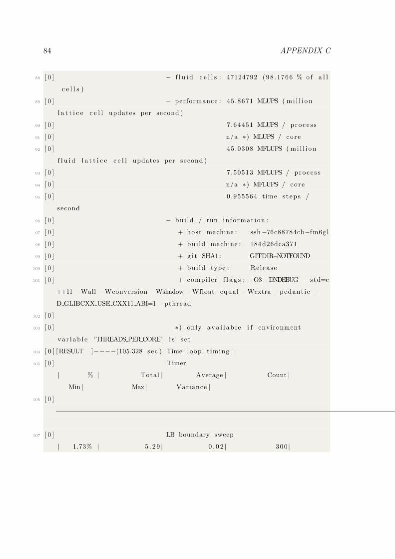
84 APPENDIX C
88 [ 0 ] − f l u i d c e l l s : 47124792 (98 .1766 % of a l l
c e l l s )
89 [ 0 ] − performance : 45 .8671 MLUPS ( m i l l i o n
l a t t i c e c e l l updates per second )
90 [ 0 ] 7 .64451 MLUPS / proce s s
91 [ 0 ] n/a ∗) MLUPS / core
92 [ 0 ] 45 .0308 MFLUPS ( m i l l i o n
f l u i d l a t t i c e c e l l updates per second )
93 [ 0 ] 7 .50513 MFLUPS / proce s s
94 [ 0 ] n/a ∗) MFLUPS / core
95 [ 0 ] 0 .955564 time s t ep s /
second
96 [ 0 ] − bu i ld / run in fo rmat ion :
97 [ 0 ] + host machine : ssh−76c88784cb−fm6gl
98 [ 0 ] + bu i ld machine : 184 d26dca371
99 [ 0 ] + g i t SHA1: GITDIR−NOTFOUND
100 [ 0 ] + bu i ld type : Re lease
101 [ 0 ] + compi ler f l a g s : −O3 −DNDEBUG −std=c
++11 −Wall −Wconversion −Wshadow −Wfloat−equal −Wextra −pedant ic −
D GLIBCXX USE CXX11 ABI=1 −pthread
102 [ 0 ]
103 [ 0 ] ∗) only a v a i l a b l e i f environment
v a r i a b l e ’THREADS PER CORE’ i s s e t
104 [ 0 ] [ RESULT ]−−−−(105.328 sec ) Time loop t iming :
105 [ 0 ] Timer
| % | Total | Average | Count |
Min | Max | Variance |
106 [ 0 ]
−−−−−−−−−−−−−−−−−−−−−−−−−−−−−−−−−−−−−−−−−−−−−−−−−−−−−−−−−−−−−−−−−−−−−−−−−−−−−−−−−−−−−−−−−−−−−−−−−−−−−−−−−−−−−−−−−−−−−−−−−−−−−−−−−−−−−−−−−−−−−−−−−−−−
107 [ 0 ] LB boundary sweep
| 1.73% | 5 . 2 9 | 0 . 0 2 | 300 |
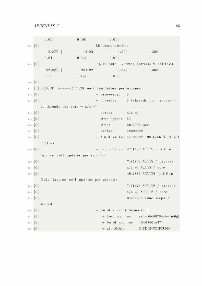
APPENDIX C 85
0 . 0 0 | 0 . 0 6 | 0 . 0 0 |
108 [ 0 ] LB communication
| 5.90% | 1 8 . 0 2 | 0 . 0 6 | 300 |
0 . 0 1 | 0 . 3 4 | 0 . 0 0 |
109 [ 0 ] s p l i t pure LB sweep ( stream & c o l l i d e )
| 92.36% | 2 8 1 . 9 2 | 0 . 9 4 | 300 |
0 . 7 3 | 1 . 1 4 | 0 . 0 0 |
110 [ 0 ]
111 [ 0 ] [ RESULT ]−−−−(105.328 sec ) S imulat ion performance :
112 [ 0 ] − p r o c e s s e s : 6
113 [ 0 ] − threads : 6 ( threads per p roce s s =
1 , threads per core = n/a ∗) )
114 [ 0 ] − co r e s : n/a ∗)
115 [ 0 ] − time s t ep s : 50
116 [ 0 ] − time : 50 .9033 sec
117 [ 0 ] − c e l l s : 48000000
118 [ 0 ] − f l u i d c e l l s : 47124792 (98 .1766 % of a l l
c e l l s )
119 [ 0 ] − performance : 47 .1483 MLUPS ( m i l l i o n
l a t t i c e c e l l updates per second )
120 [ 0 ] 7 .85804 MLUPS / proce s s
121 [ 0 ] n/a ∗) MLUPS / core
122 [ 0 ] 46 .2886 MFLUPS ( m i l l i o n
f l u i d l a t t i c e c e l l updates per second )
123 [ 0 ] 7 .71476 MFLUPS / proce s s
124 [ 0 ] n/a ∗) MFLUPS / core
125 [ 0 ] 0 .982255 time s t ep s /
second
126 [ 0 ] − bu i ld / run in fo rmat ion :
127 [ 0 ] + host machine : ssh−76c88784cb−fm6gl
128 [ 0 ] + bu i ld machine : 184 d26dca371
129 [ 0 ] + g i t SHA1: GITDIR−NOTFOUND
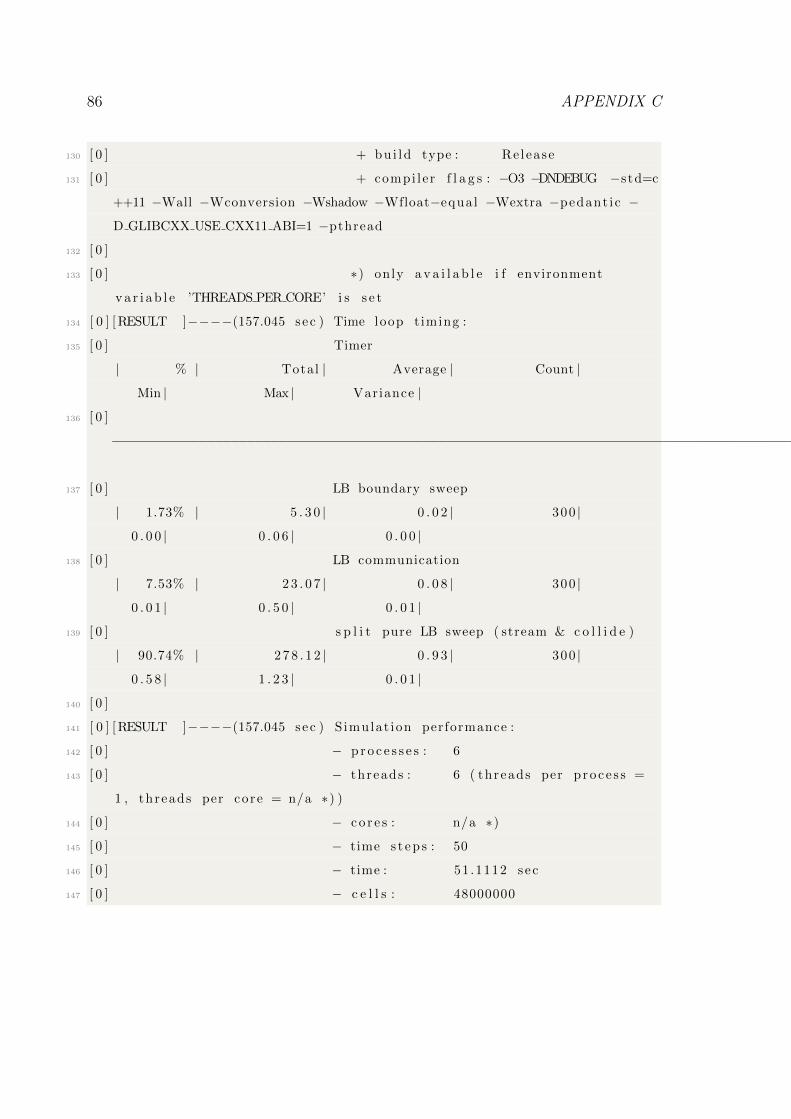
86 APPENDIX C
130 [ 0 ] + bu i ld type : Re lease
131 [ 0 ] + compi ler f l a g s : −O3 −DNDEBUG −std=c
++11 −Wall −Wconversion −Wshadow −Wfloat−equal −Wextra −pedant ic −
D GLIBCXX USE CXX11 ABI=1 −pthread
132 [ 0 ]
133 [ 0 ] ∗) only a v a i l a b l e i f environment
v a r i a b l e ’THREADS PER CORE’ i s s e t
134 [ 0 ] [ RESULT ]−−−−(157.045 sec ) Time loop t iming :
135 [ 0 ] Timer
| % | Total | Average | Count |
Min | Max | Variance |
136 [ 0 ]
−−−−−−−−−−−−−−−−−−−−−−−−−−−−−−−−−−−−−−−−−−−−−−−−−−−−−−−−−−−−−−−−−−−−−−−−−−−−−−−−−−−−−−−−−−−−−−−−−−−−−−−−−−−−−−−−−−−−−−−−−−−−−−−−−−−−−−−−−−−−−−−−−−−−
137 [ 0 ] LB boundary sweep
| 1.73% | 5 . 3 0 | 0 . 0 2 | 300 |
0 . 0 0 | 0 . 0 6 | 0 . 0 0 |
138 [ 0 ] LB communication
| 7.53% | 2 3 . 0 7 | 0 . 0 8 | 300 |
0 . 0 1 | 0 . 5 0 | 0 . 0 1 |
139 [ 0 ] s p l i t pure LB sweep ( stream & c o l l i d e )
| 90.74% | 2 7 8 . 1 2 | 0 . 9 3 | 300 |
0 . 5 8 | 1 . 2 3 | 0 . 0 1 |
140 [ 0 ]
141 [ 0 ] [ RESULT ]−−−−(157.045 sec ) S imulat ion performance :
142 [ 0 ] − p r o c e s s e s : 6
143 [ 0 ] − threads : 6 ( threads per p roce s s =
1 , threads per core = n/a ∗) )
144 [ 0 ] − co r e s : n/a ∗)
145 [ 0 ] − time s t ep s : 50
146 [ 0 ] − time : 51 .1112 sec
147 [ 0 ] − c e l l s : 48000000
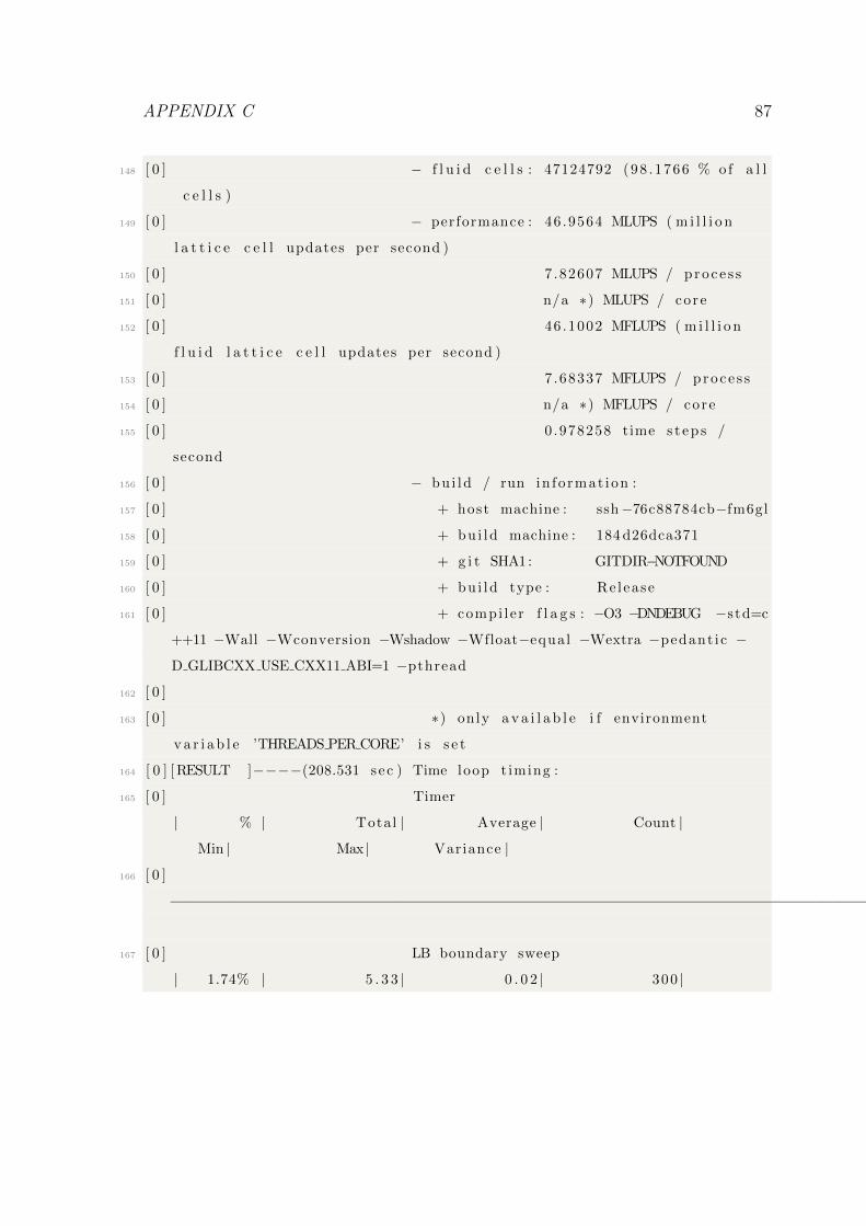
APPENDIX C 87
148 [ 0 ] − f l u i d c e l l s : 47124792 (98 .1766 % of a l l
c e l l s )
149 [ 0 ] − performance : 46 .9564 MLUPS ( m i l l i o n
l a t t i c e c e l l updates per second )
150 [ 0 ] 7 .82607 MLUPS / proce s s
151 [ 0 ] n/a ∗) MLUPS / core
152 [ 0 ] 46 .1002 MFLUPS ( m i l l i o n
f l u i d l a t t i c e c e l l updates per second )
153 [ 0 ] 7 .68337 MFLUPS / proce s s
154 [ 0 ] n/a ∗) MFLUPS / core
155 [ 0 ] 0 .978258 time s t ep s /
second
156 [ 0 ] − bu i ld / run in fo rmat ion :
157 [ 0 ] + host machine : ssh−76c88784cb−fm6gl
158 [ 0 ] + bu i ld machine : 184 d26dca371
159 [ 0 ] + g i t SHA1: GITDIR−NOTFOUND
160 [ 0 ] + bu i ld type : Re lease
161 [ 0 ] + compi ler f l a g s : −O3 −DNDEBUG −std=c
++11 −Wall −Wconversion −Wshadow −Wfloat−equal −Wextra −pedant ic −
D GLIBCXX USE CXX11 ABI=1 −pthread
162 [ 0 ]
163 [ 0 ] ∗) only a v a i l a b l e i f environment
v a r i a b l e ’THREADS PER CORE’ i s s e t
164 [ 0 ] [ RESULT ]−−−−(208.531 sec ) Time loop t iming :
165 [ 0 ] Timer
| % | Total | Average | Count |
Min | Max | Variance |
166 [ 0 ]
−−−−−−−−−−−−−−−−−−−−−−−−−−−−−−−−−−−−−−−−−−−−−−−−−−−−−−−−−−−−−−−−−−−−−−−−−−−−−−−−−−−−−−−−−−−−−−−−−−−−−−−−−−−−−−−−−−−−−−−−−−−−−−−−−−−−−−−−−−−−−−−−−−−−
167 [ 0 ] LB boundary sweep
| 1.74% | 5 . 3 3 | 0 . 0 2 | 300 |
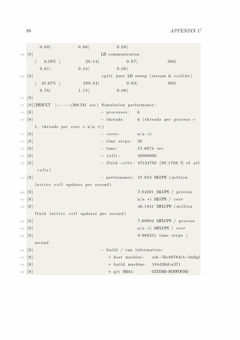
88 APPENDIX C
0 . 0 0 | 0 . 0 6 | 0 . 0 0 |
168 [ 0 ] LB communication
| 6.59% | 2 0 . 1 4 | 0 . 0 7 | 300 |
0 . 0 1 | 0 . 4 4 | 0 . 0 0 |
169 [ 0 ] s p l i t pure LB sweep ( stream & c o l l i d e )
| 91.67% | 2 8 0 . 3 4 | 0 . 9 3 | 300 |
0 . 7 6 | 1 . 1 5 | 0 . 0 0 |
170 [ 0 ]
171 [ 0 ] [ RESULT ]−−−−(208.531 sec ) S imulat ion performance :
172 [ 0 ] − p r o c e s s e s : 6
173 [ 0 ] − threads : 6 ( threads per p roce s s =
1 , threads per core = n/a ∗) )
174 [ 0 ] − co r e s : n/a ∗)
175 [ 0 ] − time s t ep s : 50
176 [ 0 ] − time : 51 .0074 sec
177 [ 0 ] − c e l l s : 48000000
178 [ 0 ] − f l u i d c e l l s : 47124792 (98 .1766 % of a l l
c e l l s )
179 [ 0 ] − performance : 47 .052 MLUPS ( m i l l i o n
l a t t i c e c e l l updates per second )
180 [ 0 ] 7 .84201 MLUPS / proce s s
181 [ 0 ] n/a ∗) MLUPS / core
182 [ 0 ] 46 .1941 MFLUPS ( m i l l i o n
f l u i d l a t t i c e c e l l updates per second )
183 [ 0 ] 7 .69902 MFLUPS / proce s s
184 [ 0 ] n/a ∗) MFLUPS / core
185 [ 0 ] 0 .980251 time s t ep s /
second
186 [ 0 ] − bu i ld / run in fo rmat ion :
187 [ 0 ] + host machine : ssh−76c88784cb−fm6gl
188 [ 0 ] + bu i ld machine : 184 d26dca371
189 [ 0 ] + g i t SHA1: GITDIR−NOTFOUND
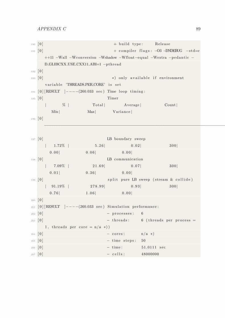
APPENDIX C 89
190 [ 0 ] + bu i ld type : Re lease
191 [ 0 ] + compi ler f l a g s : −O3 −DNDEBUG −std=c
++11 −Wall −Wconversion −Wshadow −Wfloat−equal −Wextra −pedant ic −
D GLIBCXX USE CXX11 ABI=1 −pthread
192 [ 0 ]
193 [ 0 ] ∗) only a v a i l a b l e i f environment
v a r i a b l e ’THREADS PER CORE’ i s s e t
194 [ 0 ] [ RESULT ]−−−−(260.033 sec ) Time loop t iming :
195 [ 0 ] Timer
| % | Total | Average | Count |
Min | Max | Variance |
196 [ 0 ]
−−−−−−−−−−−−−−−−−−−−−−−−−−−−−−−−−−−−−−−−−−−−−−−−−−−−−−−−−−−−−−−−−−−−−−−−−−−−−−−−−−−−−−−−−−−−−−−−−−−−−−−−−−−−−−−−−−−−−−−−−−−−−−−−−−−−−−−−−−−−−−−−−−−−
197 [ 0 ] LB boundary sweep
| 1.72% | 5 . 2 6 | 0 . 0 2 | 300 |
0 . 0 0 | 0 . 0 6 | 0 . 0 0 |
198 [ 0 ] LB communication
| 7.09% | 2 1 . 6 9 | 0 . 0 7 | 300 |
0 . 0 1 | 0 . 3 6 | 0 . 0 0 |
199 [ 0 ] s p l i t pure LB sweep ( stream & c o l l i d e )
| 91.19% | 2 7 8 . 9 9 | 0 . 9 3 | 300 |
0 . 7 6 | 1 . 0 6 | 0 . 0 0 |
200 [ 0 ]
201 [ 0 ] [ RESULT ]−−−−(260.033 sec ) S imulat ion performance :
202 [ 0 ] − p r o c e s s e s : 6
203 [ 0 ] − threads : 6 ( threads per p roce s s =
1 , threads per core = n/a ∗) )
204 [ 0 ] − co r e s : n/a ∗)
205 [ 0 ] − time s t ep s : 50
206 [ 0 ] − time : 51 .0111 sec
207 [ 0 ] − c e l l s : 48000000
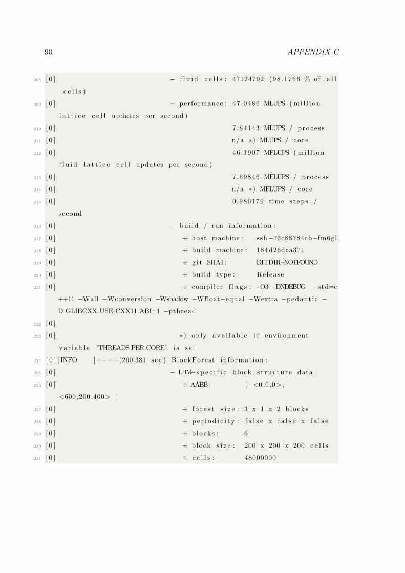
90 APPENDIX C
208 [ 0 ] − f l u i d c e l l s : 47124792 (98 .1766 % of a l l
c e l l s )
209 [ 0 ] − performance : 47 .0486 MLUPS ( m i l l i o n
l a t t i c e c e l l updates per second )
210 [ 0 ] 7 .84143 MLUPS / proce s s
211 [ 0 ] n/a ∗) MLUPS / core
212 [ 0 ] 46 .1907 MFLUPS ( m i l l i o n
f l u i d l a t t i c e c e l l updates per second )
213 [ 0 ] 7 .69846 MFLUPS / proce s s
214 [ 0 ] n/a ∗) MFLUPS / core
215 [ 0 ] 0 .980179 time s t ep s /
second
216 [ 0 ] − bu i ld / run in fo rmat ion :
217 [ 0 ] + host machine : ssh−76c88784cb−fm6gl
218 [ 0 ] + bu i ld machine : 184 d26dca371
219 [ 0 ] + g i t SHA1: GITDIR−NOTFOUND
220 [ 0 ] + bu i ld type : Re lease
221 [ 0 ] + compi ler f l a g s : −O3 −DNDEBUG −std=c
++11 −Wall −Wconversion −Wshadow −Wfloat−equal −Wextra −pedant ic −
D GLIBCXX USE CXX11 ABI=1 −pthread
222 [ 0 ]
223 [ 0 ] ∗) only a v a i l a b l e i f environment
v a r i a b l e ’THREADS PER CORE’ i s s e t
224 [ 0 ] [ INFO ]−−−−(260.381 sec ) BlockForest in fo rmat ion :
225 [ 0 ] − LBM−s p e c i f i c b lock s t r u c t u r e data :
226 [ 0 ] + AABB: [ <0 ,0 ,0> ,
<600 ,200 ,400> ]
227 [ 0 ] + f o r e s t s i z e : 3 x 1 x 2 b locks
228 [ 0 ] + p e r i o d i c i t y : f a l s e x f a l s e x f a l s e
229 [ 0 ] + b locks : 6
230 [ 0 ] + block s i z e : 200 x 200 x 200 c e l l s
231 [ 0 ] + c e l l s : 48000000
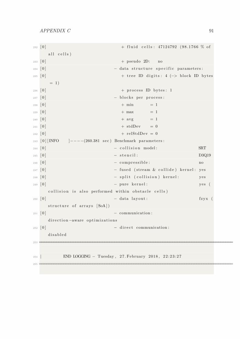
APPENDIX C 91
232 [ 0 ] + f l u i d c e l l s : 47124792 (98 .1766 % of
a l l c e l l s )
233 [ 0 ] + pseudo 2D: no
234 [ 0 ] − data s t r u c t u r e s p e c i f i c parameters :
235 [ 0 ] + t r e e ID d i g i t s : 4 (−> block ID bytes
= 1)
236 [ 0 ] + proce s s ID bytes : 1
237 [ 0 ] − b locks per p roce s s :
238 [ 0 ] + min = 1
239 [ 0 ] + max = 1
240 [ 0 ] + avg = 1
241 [ 0 ] + stdDev = 0
242 [ 0 ] + relStdDev = 0
243 [ 0 ] [ INFO ]−−−−(260.381 sec ) Benchmark parameters :
244 [ 0 ] − c o l l i s i o n model : SRT
245 [ 0 ] − s t e n c i l : D3Q19
246 [ 0 ] − compres s ib l e : no
247 [ 0 ] − fu sed ( stream & c o l l i d e ) ke rne l : yes
248 [ 0 ] − s p l i t ( c o l l i s i o n ) ke rne l : yes
249 [ 0 ] − pure ke rne l : yes (
c o l l i s i o n i s a l s o performed with in o b s t a c l e c e l l s )
250 [ 0 ] − data layout : f zyx (
s t r u c t u r e o f a r rays [ SoA ] )
251 [ 0 ] − communication :
d i r e c t i o n−aware op t im i za t i on s
252 [ 0 ] − d i r e c t communication :
d i s ab l ed
253 ================================================================================
254 | END LOGGING − Tuesday , 27 . February 2018 , 22 : 23 : 27
255 ================================================================================

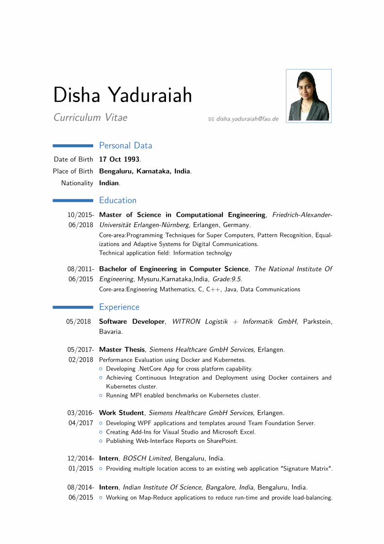
Disha YaduraiahCurriculum Vitae B [email protected]
Personal DataDate of Birth 17 Oct 1993.Place of Birth Bengaluru, Karnataka, India.
Nationality Indian.
Education10/2015-06/2018
Master of Science in Computational Engineering, Friedrich-Alexander-Universität Erlangen-Nürnberg, Erlangen, Germany.Core-area:Programming Techniques for Super Computers, Pattern Recognition, Equal-izations and Adaptive Systems for Digital Communications.Technical application field: Information technolgy
08/2011-06/2015
Bachelor of Engineering in Computer Science, The National Institute OfEngineering, Mysuru,Karnataka,India, Grade:9.5.Core-area:Engineering Mathematics, C, C++, Java, Data Communications
Experience05/2018 Software Developer, WITRON Logistik + Informatik GmbH, Parkstein,
Bavaria.
05/2017-02/2018
Master Thesis, Siemens Healthcare GmbH Services, Erlangen.Performance Evaluation using Docker and Kubernetes.{ Developing .NetCore App for cross platform capability.{ Achieving Continuous Integration and Deployment using Docker containers and
Kubernetes cluster.{ Running MPI enabled benchmarks on Kubernetes cluster.
03/2016-04/2017
Work Student, Siemens Healthcare GmbH Services, Erlangen.{ Developing WPF applications and templates around Team Foundation Server.{ Creating Add-Ins for Visual Studio and Microsoft Excel.{ Publishing Web-Interface Reports on SharePoint.
12/2014-01/2015
Intern, BOSCH Limited, Bengaluru, India.{ Providing multiple location access to an existing web application "Signature Matrix".
08/2014-06/2015
Intern, Indian Institute Of Science, Bangalore, India, Bengaluru, India.{ Working on Map-Reduce applications to reduce run-time and provide load-balancing.